

Cisco AIR-PCI340, Aironet 340, Aironet 350, Aironet CB20A Installation And Configuration Manual
Page 1

Corporate Headquarters
Cisco Systems, Inc.
170 West Tasman Drive
San Jose, CA 95134-1706
USA
http://www.cisco.com
Tel: 408 526-4000
800 553-NETS (6387)
Fax: 408 526-4100
Cisco Aironet 340, 350, and CB20A
Wireless LAN Client Adapters
Installation and Configuration Guide
for Windo ws
Text Part Number: OL-1394-07
Page 2

THE SPECIFICATIONS AND INFORMATION REGARDING THE PRODUCTS IN THIS M ANUAL ARE SUBJECT TO CHA NGE WITHOUT NO TICE. ALL
STATEMENTS, INFORMATION, AND RECOMMENDATIONS IN THIS MANUAL ARE BELIEVED TO BE ACCURATE BUT ARE PRESENTED WITHOUT
WARRANTY OF ANY KIND, EXPRESS OR IMPLIED. USERS MUST TAKE FULL RESPONSI BILITY FOR THEIR APPLICA TION OF ANY PRODUCT S.
THE SOFTWARE LICENSE AND LIMITED WARRANTY FOR THE ACCOMPANYING PRODUCT ARE SET FORT H IN THE INFORMATION PACKET T HAT
SHIPPED WITH THE PRODUCT AND ARE INCORPORATED HEREIN BY THIS REFERENCE. IF YOU ARE UNABLE TO LOCATE THE SOFTWARE LICENSE
OR LIMITED WARRANTY, CONTACT YOUR CISCO REPRESENTATIVE FOR A COPY.
The following information is for FCC compliance of Class A devices: This equipment has been tested and found to comply with the limits for a Class A digital device, pursuant
to part 15 of the FCC rules. These limits are designed to provide reasonable protection against harmful interference when the equipment is operated in a commercial
environment. This equipment generates, uses, and can radiate radio-frequency energy and, if not installed and used in accor dance with the instruction manual, may cause
harmful interference to radio communications. Operation of this equipment in a residential area is likely to cause harmful interference, in which case users will be required
to correct the interference at their own expense.
The following information is for FCC compliance of Class B devices: The equipment described in this manual generates and may radiate radio-frequency energy. If it is not
installed in accordance with Cisco’s installation instructions, it may cause interference with radio and television reception. This equipment has been tested and found to
comply with the limits for a Class B digital device in accordance with the specifications in part 15 of the FCC rules. These specifications are designed to provide reasonable
protection against such interference in a residential installation. However, there is no guarantee that interference will not occur in a particular installation.
Modifying the equipment without Cisc o’s writ ten author ization m ay resul t in the equi pment no lo nger comp lyi ng with FCC requi rements for Class A or Class B digital
devices. In that event, your right to use the equ ipment may be limit ed by FCC regul ations , and you may be requir ed to correct a ny interference to radio or television
communications at your own expense.
You can determine whether your equipment is causing interference by turning it off. If the interferen ce stops, it was probably caused by the Cisco equipment or one of its
peripheral devices. If the equipment causes interference to radio or television reception, try to correct the interference by using one or more of the followi ng measures:
• Turn the television or radio antenna unt il the int erference st ops.
• Move the equipment to one side or the other of the televisio n or radi o.
• Move the equipment farther away from the te levision or radio.
• Plug the equipment into an outlet that is on a di fferent cir cuit from the televi sion o r radio. (That is, make certain th e equipment and the te levision or radio are on circuit s
controlled by different circuit breaker s or fuses.)
Modifications to this product no t author ized by Cis co Syst ems, Inc. coul d voi d the FCC appro val and ne gate your authorit y to op erate the pr odu ct.
The Cisco implementation of TCP head er compressi on is an adap tation of a program developed by the Universi ty of Ca lifornia, Berk eley (UCB) as part of UCB ’s public
domain version of the UNIX operatin g system. All rights reserved . Copyri ght © 1981 , Rege nts of the Uni versity of Calif ornia.
NOTWITHSTANDING ANY OTHER WARRANTY HEREIN, ALL DOCUMENT FILES AND SOFTWARE OF THE SE SUPPLIERS ARE PROVIDED “AS IS” WITH
ALL FAULTS. CISCO AND THE ABOVE-NAMED SUPPLIERS DISCLAI M ALL WARRANTIE S, EXPRESSED OR IMPLIED, INCLUDING, WITHOUT
LIMITATION, THOSE OF MERCHANTABILITY, FITNESS FOR A PARTICULAR PURPOSE AND NO NINFRINGEM ENT OR ARISING FROM A COURS E OF
DEALING, USAGE, OR TRADE PRACTICE.
IN NO EVENT SHALL CISCO OR ITS SUPPLIERS BE LIABLE FOR ANY INDIRECT, SPECIAL, CONSEQUENTIAL, OR INCIDENTAL DAMAGES, INCLUDING ,
WITHOUT LIMITATION, LOST PROFITS OR LOSS OR DAMAGE TO DATA ARISING OUT OF THE USE OR INABILITY TO USE THIS MANUAL, EVEN IF CISCO
OR ITS SUPPLIERS HAVE BEEN ADVISED OF THE POSSIBILITY OF SUCH DAMAGE S.
CCIP, CCSP, the Cisco Arrow logo, the Cisco Powered Network mark, Cisco Unity, Follow Me Browsing, FormShare, and StackWise are trademarks of Cisco Systems, Inc.;
Changing the Way We Work, Live, Play, and Learn, and iQuick Study are service marks of Cisco Systems, Inc.; and Aironet, ASIST, BPX, Catalyst, CCDA, CCDP, CCIE,
CCNA, CCNP, Cisco, the Cisco Certified Internetwork Expert logo, Cisco IOS, the Cisco IOS logo, Cisco Press, Cisco Systems, Cisco Systems Capital, the Cisco Systems
logo, Empowering the Internet Generation, Enterprise/Solver, EtherChannel, EtherSwitch, Fast Step, GigaStack, Internet Quotient, IOS, IP/TV, iQ Expertise, the iQ logo, iQ
Net Readiness Scorecard, LightStream, MGX, MICA, the Networker s lo go, Networking Academy, Network Registrar, Packet, P IX, Post-Routing, Pre-Routing, Rate M UX,
Registrar, ScriptShare, SlideCast, SMARTnet, StrataView Plus, Stratm, SwitchProbe, TeleRouter, The Fastest Way to Increase Your Internet Quotient, TransPath, and VCO
are registered trademarks of Cisco Systems, Inc. and/or its affiliates in the U.S. and certain other countries.
All other trademarks mentioned in this document or Web site are the property of their respective owners. The use of the word partner does not imply a partnership relationship
between Cisco and any other company. (0304 R)
Cisco Aironet 340, 350, and CB20A Wireless LAN Client Adapters Installa tion and C onfiguration Gu ide fo r Windows
Copyright © 2001-2003 Cisco Sys tems, Inc.
All rights reserved.
Page 3

iii
Cisco Aironet 340, 350, and CB20A Wireless LAN Client Adapters Installation and Configuration Guide for Windows
OL-1394-07
CONTENTS
Preface xi
Audience xii
Purpose xii
Organization xii
Conventions xiii
Related Publications xv
Obtaining Documentation xv
Cisco.com xv
Documentation CD-ROM xv
Ordering Documentation xvi
Documentat ion Feedback xvi
Obtaining Technical Assistance xvi
Cisco TAC Website xvi
Opening a TAC Ca se xvii
TAC Case Priority Definitions xvii
Obtaining Additional Publicati ons and Information xvii
CHAPTER
1 Product Overview 1-1
Introduction to the Client Adapters 1-2
Terminology 1-3
Hardware Components 1-3
Radio 1-3
Radio Antenna 1-4
LEDs 1-4
Software Components 1-5
Radio Firmware 1-5
Driver 1-5
Client Utilities 1-6
Overview of ACU 1-6
Buttons on the ACU Scree ns 1-8
Network Configurations Using Client Adapters 1-8
Ad Hoc Wireless LAN 1-9
Wireless Infrastructure with Workstations Accessing a Wired LAN 1-10
Page 4

Contents
iv
Cisco Aironet 340, 350, and CB20A Wireless LAN Client Adapters Installation and Configuration Guide for Windows
OL-1394-07
CHAPTER
2 Preparing for Installation 2-1
Safety information 2-2
FCC Safety Compliance Statement 2-2
Safety Guidelines 2-2
Warnings 2-3
Unpacking the Client Adapter 2-3
Package Contents 2-3
System Requirements 2-4
Site Requirements 2-5
For Infrastruc ture Devices 2-5
For Client Devices 2-6
CHAPTER
3 Installing the Client Adapter 3-1
Installing or Upgrading the Client Ada pter Software 3-2
Installing or Upgrading the Client Adapter Software on Windows 98, 98 SE, 2000, Me, or XP 3-2
Installing or Upgr ading the Client Adapt er Software on Windows NT 3-12
Verifying Installation 3-22
Deciding How to Configure Your Client Adapter (Windows XP Only) 3-22
Selecting Among Several Installed Client Adapters 3-24
CHAPTER
4 Using the Profile Manager 4-1
Overview of Profile Manager 4-2
Opening Profile Manager 4-2
Creating a New Pr ofile 4-3
Including a Profile in Auto Profile Se lection 4-4
Selecting the Active Profile 4-6
Modifying a Profile 4-7
Editing a Profile 4-7
Setting a Profile to Default Values 4-8
Renaming a Prof ile 4-8
Deleting a Prof ile 4-8
Importing and Exporting Profiles 4-9
Importing a Profile 4-9
Exporting a Profile 4-9
Granting or Denying Access to Non-Administrative Users 4-10
Page 5

Contents
v
Cisco Aironet 340, 350, and CB20A Wireless LAN Client Adapters Installation and Configuration Guide for Windows
OL-1394-07
CHAPTER
5 Configuring the Client Adapter 5-1
Overview 5-2
Setting System Parameters 5-3
Setting RF Network Parameters 5-7
Setting Advan ce d In fr as tructure Param e te rs 5-14
Setting Advanced Ad Hoc Parameters 5-17
Setting Network Sec urity Parameters 5-21
Setting the All ow A ss o ciation to Mixed C ells Parameter 5-22
Overview of Security Features 5-22
Static WEP Keys 5-23
EAP (with Dynamic WEP Keys) 5-23
Wi-Fi Protected Access (WPA) 5-26
Fast Roaming (CCKM) 5-26
Reporting Access Points that Fail LEAP Authentication 5-27
Additional WEP Key Security Features 5-28
Synchroniz in g Se c urity Feature s 5-29
Using Static WEP 5-32
Entering a New Static WEP Key 5-32
Overwriting an Exist ing Static WEP Key 5-34
Disabling Static WEP 5-35
Enabling LEAP 5-35
Enabling Host-Based EAP 5-39
Enabling Host-Based EAP Authentication in ACU 5-40
Enabling WPA (Windows 2000 or XP Only - Optional) 5-41
Enabling EAP Authentication in Windows 5-44
Disabling LEAP or Host-Based EAP 5-51
Disabling LEAP 5-51
Disabling Host-Based EAP 5-51
CHAPTER
6 Using EAP Authentication 6-1
Overview 6-2
Using LEAP 6-2
Using LEAP with the Windows Username and Password 6-3
After Profile Selection or Card Insertion 6-3
After a Reboot or Logon 6-4
After Your LEAP Credentials Expire 6-5
Page 6

Contents
vi
Cisco Aironet 340, 350, and CB20A Wireless LAN Client Adapters Installation and Configuration Guide for Windows
OL-1394-07
Using LEAP with an Automatically Prompted Login 6-6
After Profile Selection or Card Insertion 6-6
After a Reboot or Logon 6-7
After Your LEAP Credentials Expire 6-9
Using LEAP with a Manually Prompted Login 6-9
After Profile Selection 6-9
After a Reboot, Logon, or Card Insertion 6-12
After Your LEAP Credentials Expire 6-13
Using LEAP with a Saved Username and Password 6-14
After Profile Selection or Card Insertion 6-14
After a Reboot or Logon 6-14
After Your LEAP Credentials Expire 6-15
Using EAP-TLS 6-15
After Profile Selection or Card Insertion 6-15
After a Reboot or Logon 6-16
Using PEAP 6-16
After Profile Se lection, Card In sertion, Reboot, or Logon 6-16
Windows NT or 2000 Domain Databases or LDAP Databases Only 6-16
OTP Databases Only 6-17
After Your Password Expires (Windows NT or 2000 Domain Databases Only) 6-19
After Your PIN Expires (OTP Databases Only) 6-20
Using EAP-SIM 6-21
If You Are Prompted for the PIN 6-21
If the PIN Is Stored on the Computer 6-22
Restarting the Authentication Proce ss 6-22
CHAPTER
7 Performing Diagnostics 7-1
Overview of ACU Diagnostic Tools 7-2
Setting Parameters that Affect ACU Diagnostic Tools 7-3
Viewing the Current Status of Your Client Adapter 7-4
Viewing Statistics for Your Client Adapter 7-12
Viewing the Link Status Meter 7-16
Running an RF Link Test 7-18
CHAPTER
8 Using the Aironet Client Monitor (ACM) 8-1
Overview of ACM 8-2
The ACM Icon 8-2
Tool Tip Window 8-3
Page 7

Contents
vii
Cisco Aironet 340, 350, and CB20A Wireless LAN Client Adapters Installation and Configuration Guide for Windows
OL-1394-07
Pop-Up Menu 8-5
About 8-5
Exit 8-6
Launch Aironet Client Utility 8-6
Troubleshooting 8-6
Preferences 8-6
Turn Radio On/Off 8-7
Reauthenticate 8-8
Select Profile 8-8
Show Connection Stat us 8-9
CHAPTER
9 Routine Procedures 9-1
Inserting and Removing a Client Adapter 9-2
Inserting a Client Adapter 9-2
Inserting a PC Card or PC-Cardbus Car d 9-2
Inserting a PCI Card 9-3
Removing a Cl ie nt Ad ap te r 9-4
Removing a PC Ca rd or PC -C a rd b us Card 9-4
Removing a PCI Ca rd 9-5
Client Adapter Software Procedures 9-5
Finding the Install Wizard Version 9-5
Upgrading the Client Adapter Software 9-6
Uninstalling the Client Adapter Software 9-6
Finding the Driv er Version 9-7
Firmware Procedures 9-8
Finding the Firmware Version 9-8
Upgrading the Firmware 9-8
Preventing the Driver from Upgrading the Firmware 9-10
ACU Procedu r es 9-12
Opening ACU 9-12
Exiting ACU 9-13
Modifying ACU In st al la tion Settings 9-13
Finding the Version of ACU 9-13
Adding the ACU Icon to or Removing it from the Desktop 9-14
Accessing Online Help 9-14
ACM Procedures 9-15
Restarting the Client Adapter 9-15
Turning Your Client Adapter’s Radio On or Off 9-15
Uninstalling the Microsoft Hot Fix 9-16
Page 8

Contents
viii
Cisco Aironet 340, 350, and CB20A Wireless LAN Client Adapters Installation and Configuration Guide for Windows
OL-1394-07
CHAPTER
10 Troubleshooting 10-1
Accessing the Lat est Troublesho oting Informati on 10-2
Interpretin g th e In di ca to r LEDs 10-2
Troubleshooti ng the Client Adapter 10-3
Using the Troubleshooting Utility 10-4
Diagnosing Your Client Adapter’s Operation 10-4
Saving the Detailed Report to a Text File 10-6
Accessing Online Help 10-7
Client Adapter Recognition Problems 10-7
Resolving Resource Conflicts 10-8
Resolving Resour ce Conflicts in Windows 98, 98 SE, and Me 10-8
Resolving Resour ce Conflicts in Windows NT 10-9
Resolving Resour ce Conflicts in Windows 2000 10-9
Resolving Resour ce Conflicts in Windows XP 10-10
Problems Associating to an Access Point 10-11
Problems Authenti cating to an Access Point 10-11
Problems Connecting to the Network 10-11
Prioritizing Ne twork Connections (Windows 2000 and XP Only) 10-11
Losing Association upon Resuming from Suspe nd Mode
(Windows NT and Mini PCI Cards Only)
10-12
Parameters Missing from Profile Manage r Screen 10-12
Windows Wireless Network Connection Icon Shows Unavailable Connection (Windows XP
Only)
10-12
LEAP Login Screen Does Not Appear Before Windows Login Screen (Windows 98, 98 SE, and Me
Only)
10-13
Microsoft Ho t Fix (W i nd o w s 98 and 98 SE Only) 10-13
Error Message s 10-13
General Error Messa ges 10-14
Installation Error Messages 10-18
LEAP Authentication Error Messages 10-20
PEAP Authentication Error Messages 10-23
For All PEAP-Supported Databases 10-23
For Windows NT or 2000 Domain Dat abases 10-24
For All OTP Databases 10-25
For OTP Databases Using Secure Computing SofToken Version 1.3 10-26
For OTP Databases Using Secure Computing SofToken II Version 2.0 10-27
For OTP Databases Using RSA SecurID Version 2.5 10-28
EAP-SIM Auth en tication Erro r Messages 10-28
Page 9

Contents
ix
Cisco Aironet 340, 350, and CB20A Wireless LAN Client Adapters Installation and Configuration Guide for Windows
OL-1394-07
APPENDIX
A Technical Specifications A-1
APPENDIX
B Translated Safety Warnings B-1
Explosive Device Proximity Warning B-2
Dipole Antenna Installation Warning B-3
Warning for Lap to p U se rs B-4
APPENDIX
C Declarations of Conformity and Regulatory Information C-1
Manufacturer’s Federal Communication Commission Declaration of Conformity Statement C-2
Department of Communications – Canada C-3
Canadian Complian ce Statement C-3
European Community, Switzerland, Norway, Iceland, and Liechtenstein C-4
Declaration of Conformity with Regard to the R&TTE Directive 1999/ 5/EC C-4
2.4-GHz Clie nt Ad ap te rs C-5
5-GHz Client Ad ap te rs C-6
Declaration of Conformity for RF Exposure C-6
Guidelines for Operating Cisco Airone t Wireless LAN Client Adapt ers in Japan C-6
Japanese Translation C-6
English Translation C-7
Administrative Rul es for Cisco Aironet Wireless LAN Client Adapters i n Taiwan C-7
2.4- and 5-GHz Clie nt Adapters C-7
Chinese Translation C-7
English Translation C-8
5-GHz Client Ad ap te rs C-8
Chinese Translation C-8
English Translation C-8
APPENDIX
D Channels, Power Levels, and Antenna Gains D-1
Channels D-2
IEEE 802.11a D-2
IEEE 802.11b D-3
Maximum Power Levels and Ant en na Gains D-4
IEEE 802.11a D-4
IEEE 802.11b D-4
Page 10

Contents
x
Cisco Aironet 340, 350, and CB20A Wireless LAN Client Adapters Installation and Configuration Guide for Windows
OL-1394-07
APPENDIX
E Configuring the Client Adapter through the Win dows XP Operating System E-1
Overview E-2
Overview of Security Features E-2
Static WEP Keys E-2
EAP (with Dynamic WEP Keys) E-2
Wi-Fi Protected Access (WPA) E-4
Configuring the Client Adapter E-5
Enabling EAP-TLS Authentication E-10
Enabling PEA P Aut h en tication E-13
Enabling EAP -S IM Authentica ti on E-16
Associating to an Access Point Using Windows XP E-18
Viewing the Current Status of Your Client Adapter E-19
APPENDIX
F Performing a Site Survey F-1
Overview F-2
Guidelines F-2
Additional Information F-2
Specifying Signal Strength Units F-3
Using Passive Mode F-3
Using Active Mode F-7
Forcing the Clie nt Adapter to Reassociate F-13
G
LOSSARY
I
NDEX
Page 11

xi
Cisco Aironet 340, 350, and CB20A Wireless LAN Client Adapters Installation and Configuration Guide for Windows
OL-1394-07
Preface
The preface pr ovide s an overv iew of t h e Ci sco A ironet 340, 350, and CB 20A Wireless LAN Client
Adapters Installation and Configuration Guide for Windows, references related publications, and
explains how to obtain ot h er do cu ment atio n a nd te ch nica l a ssist ance , if ne cessa ry.
The following topics are covered in this section:
• Audience, page xii
• Purpose, page xii
• Organization, page xii
• Conventions, page xiii
• Related Publications, page xv
• Obtaining Docu ment ati on , pa ge xv
• Obtaining Technical Assistance, page xvi
• Obtaining Additional Publications and Information, page xvii
Page 12

xii
Cisco Aironet 340, 350, and CB20A Wireless LAN Client Adapters Installation and Configuration Guide for Windows
OL-1394-07
Preface
Audience
Audience
This publication is for the pe rson res ponsib le for instal ling, configuri ng, and main taining a Ci sco
Aironet 340, 350, or C B20A Wireless LA N Cl ient A dapt er o n a c om pute r runn in g Mi crosof t Windows
98, 98 SE, NT, 2000, Me, or XP. This person should be familiar wi th c omput ing devices a nd with
network terms and concep ts.
Purpose
This publication descri bes t he Cisc o Airo ne t 340, 350, and CB20 A cl ient a dapt ers and explains how to
install, configure, an d t roubl es hoot the m.
Note This version of the Cisco Aironet 340, 350, and CB20A Wireless LAN Client Adapters In stalla tion and
Configuration Guide for Windows pertains specif icall y to versions of the clie nt adapter software that are
installed through an Inst all Wizard file. If you are using , installi ng, or upgra ding to versio ns of client
adapter software tha t do not use the Ins tall Wizard, refer t o version OL-1 394-04 of this manu al for
information and instruc tions.
Organization
This publicat ion co ntai n s th e f ol lowing ch ap te rs :
• Chapter 1, “Product Overview,” describes the client adapters and their hardware and software
components and illustrates two common network configurations.
• Chapter 2, “Preparing for Installation,” provides information that you need to know before installing
a client adapter, such as safety information and system requirements.
• Chapter 3, “Installing the Client Adapter,” provides instructions for installing client adapter
software.
• Chapter 4, “Using the Profile Manager,” explains how to use the ACU profile manager feature to
create and manage profiles fo r your clien t adapt er.
• Chapter 5, “Configuring the Client Adapter,” explains how to change the configuration parameters
for a specific profile.
• Chapter 6, “Using EAP Authentic ation,” e xplain s the sequen ce of e v ents that occ urs and the actions
you must take when a profile that is set for EAP authentication is selected for use.
• Chapter 7, “Performing Diagnostics,” explains how to use ACU to perform user-level diagnostics.
• Chapter 8, “Using the Aironet Client Monitor (ACM),” explains how to use the A irone t C lient
Monitor (ACM) to access status information ab out your cli ent adapter and perfor m basic tasks.
• Chapter 9, “Routine Procedures,” provides procedures for common tasks related to the client
adapters, such as uninstalling client adapter software and restarting an adapter.
• Chapter 10, “Troubleshooting,” provides information for diagnosi ng and co rrecti ng comm on
problems that may be encoun tered w hen inst alling or op erati ng a client ad apte r.
• Appendix A, “Technical Specifications,” lists the physica l, radio, power, and regulatory
specifications for the client adapters.
Page 13

xiii
Cisco Aironet 340, 350, and CB20A Wireless LAN Client Adapters Installation and Configuration Guide for Windows
OL-1394-07
Preface
Conventions
• Appendix B, “Translated Safety Warnings,” provides translations of client adapter safety warnings
in nine languages.
• Appendix C, “D ecl ara tio ns o f Conf or mit y and Regula tory I nfo rm ation, ” provides declarations of
conformity and regul at ory inf orm ati on f or the cl ient ad ap ters.
• Appendix D, “Cha nnels, Power Levels, and Antenna Gains,” lists th e IEEE 802.11a an d IEEE
802.11b channels supported by the w orld's regula tory domains as well as the maximum power le vels
and antenna gains allowed per dom ain.
• Appendix E, “C onfigur ing the Cli ent Ada pte r th rou gh the Windows XP Operati ng Syste m,”
explains how to configure and use your client adapter wi th Windows XP.
• Appendix F, “Performing a Site Survey,” shows people who are responsible for conducting a sit e
survey how they can use ACU to determine the best placement for infrastructure devices within a
wireless network.
Conventions
This publication uses the following conventions to convey instructions and informa tion:
• Commands and keywords are in boldface.
• Variables are in italics.
• Configuration parameters are capitalized.
• Notes, cautions, and warnings use the following conventions and symbols:
Note Means reader take note. Notes contain helpful suggestions or references to materials not contained in
this manual.
Caution Means rea de r be care ful. In this situation, you might do something that could result in equipment
damage or loss of data.
Warning
This warning symbol means danger. You are in a situation that could cause bodily injury . Before you
work on any equipment, be aware of the hazards involved with electrical circuitry and be familiar
with standard practices for preventing accidents. (To see translations of the warnings that appear
in this publication, refer to the appendix “Translated Safety Warnings.”)
Waarschuwing
Dit waarschuwingssymbool betekent gevaar. U verkeert in een situatie die lichamelijk letsel kan
veroorzaken. Voordat u aan enige apparatuur gaat werken, dient u zich bewust te zijn van de bij
elektrische schakelingen betrokken risico’s en dient u op de hoogte te zijn van standaard
maatregelen om ongelukken te voorkomen. (Voor vertalingen van de waarschuwingen die in deze
publicatie verschijnen, kunt u het aanhangsel “Translated Safety Warnings” (Vertalingen van
veiligheidsvoorschriften) raadplegen.)
Page 14

xiv
Cisco Aironet 340, 350, and CB20A Wireless LAN Client Adapters Installation and Configuration Guide for Windows
OL-1394-07
Preface
Conventions
Varoitus
Tämä varoitusmerkki merkitsee vaaraa. Olet tilanteessa, joka voi johtaa ruumiinvammaan. Ennen
kuin työskentelet minkään laitteiston parissa, ota selvää sähkökytkentöihin liittyvistä vaaroist a ja
tavanomaisista onnettomuuksien ehkäisykeinoista. (Tässä julkaisussa esiintyvien varoitust en
käännökset löydät liitteestä "Translated Safety Warnings" (käännetyt turvallisuutta koskevat
varoitukset).)
Attention
Ce symbole d’avertissement indique un danger. Vous vous trouvez dans une situation pouvant
entraîner des blessures. Avant d’accéder à cet équipement, soyez conscient des dangers posés par
les circuits électriques et familiarisez-vous avec les procédures courantes de prévention des
accidents. Pour obtenir les traductions des mises en garde figurant dans cet te publication, veuil lez
consulter l’annexe intitulée « Translated Safety Warnings » (Traduction des avis de sécurité).
Warnung
Dieses Warnsymbol bedeutet Gefahr. Sie befinden sich in einer Situation, die zu einer
Körperverletzung führen könnte. Bevor Sie mit der Arbeit an irgendeinem Gerät beginnen, seien Sie
sich der mit elektrischen Stromkreisen verbundenen Gefahren und der Standardpraktiken zur
Vermeidung von Unfällen bewußt. (Übersetzungen der in dieser Veröffentlichung enthaltenen
Warnhinweise finden Sie im Anhang mit dem Titel “Translated Safety Warnings” (Übersetzung der
Warnhinweise).)
Avvertenza
Questo simbolo di avvertenza indica un pericolo. Si è in una situazione che può causare infortuni.
Prima di lavorare su qualsiasi apparecchiatura, occorre conoscere i pericoli relativi ai circuiti
elettrici ed essere al corrente delle pratiche standard per la prevenzione di incidenti. La traduzione
delle avvertenze riportate in questa pubblicazione si trova nell’appendice, “Translated Safety
Warnings” (Traduzione delle avvertenze di sicurezza).
Advarsel
Dette varselsymbolet betyr fare. Du befinner deg i en situasjon som kan føre til personskade. Før du
utfører arbeid på utstyr, må du være oppmerksom på de faremomentene som elektriske kretser
innebærer, samt gjøre deg kjent med vanlig praksis når det gjelder å unngå ulykker. (Hvis du vil se
oversettelser av de advarslene som finnes i denne publikasjonen, kan du s e i vedlegget "Translated
Safety Warnings" [Oversatte sikkerhetsadvarsler].)
Aviso
Este símbolo de aviso indica perigo. Encontra-se numa situação que lhe poderá causar danos fisicos.
Antes de começar a trabalhar com qualquer equipamento, familiarize-se com os perigos
relacionados com circuitos eléctricos, e com quaisquer práticas comuns que possam prevenir
possíveis acidentes. (Para ver as traduções dos avisos que constam desta publicação, consulte o
apêndice “Translated Safety Warnings” - “Traduções dos Avisos de Segurança”).
¡Advertencia!
Este símbolo de aviso significa peligro. Existe riesgo para su integridad física. Antes de manipular
cualquier equipo, considerar los riesgos que entraña la corriente eléctrica y familiarizarse con los
procedimientos estándar de prevención de accidentes. (Para ver traducciones de las advertencias
que aparecen en esta publicación, consultar el apéndice titulado “Translated Safety Warnings.”)
Varning!
Denna varningssymbol signalerar fara. Du befinner dig i en situation som kan leda till personskada.
Innan du utför arbete på någon utrustning måste du vara medveten om farorna med elkretsar och
känna till vanligt förfarande för att förebygga skador. (Se förklaringar av de varningar som
förekommer i denna publikation i appendix "Translated Safety Warnings" [Översatta
säkerhetsvarningar].)
Page 15

xv
Cisco Aironet 340, 350, and CB20A Wireless LAN Client Adapters Installation and Configuration Guide for Windows
OL-1394-07
Preface
Related Publications
Related Publications
For more informati on a bou t Ci sco Air onet 340, 35 0, and CB2 0A Wireless L AN Cli ent Ada pter s f or
Windows, refer to the following publications:
• Release Notes for Cisco Aironet 340, 350, and CB20A Clien t Adapter Instal l Wizard for Windows
• Release Notes for Cisco Aironet 340, 350, and CB20A Cli ent Adapter Firmware
For more information a bou t re la ted Ci sco A iro ne t pr odu cts, ref er t o t he pu bl icat ions for y our
infrastructure device. You can access Cisco Aironet technical documentation at this URL:
http://www.cisco.com/en/US/products/hw/wireless/index.html
Obtaining Documentation
Cisco provides several ways to obtain documentation, techn ical assistance , and other tec hnical
resources. These sect ion s expla in h ow to obta in te chni cal infor ma tion fr om Ci sco Sy stem s.
Cisco.com
You ca n acc ess t he m ost c ur rent Cisc o doc um ent ation on the World Wide We b at thi s URL :
http://www.cisco.com/univercd/home/home.htm
You can access the Cisco website at this URL:
http://www.cisco.com
International Cisco websites can be accessed from this URL:
http://www.cisco.com/public/countries_languages.shtml
Documentation CD-ROM
Cisco documentation and additional literature are available in a Cisco Documentation CD-ROM
package, which may have shipped with your product. The Documentation CD-ROM is updated regularly
and may be more curre nt than printed do cumentati on. The CD-R OM packag e is av ailable as a single unit
or through an an nua l o r q uart erly subsc rip tio n.
Registered Cisco.com u sers c a n orde r a sing l e Do cume nta tio n CD- ROM (product num be r
DOC-CONDOCCD=) through the Cisco Ordering tool:
http://www.cisco.com/en/US/partner/ordering/ordering_pla ce_order _ordering_ tool_launch. html
All users can order a nnua l or qu art erly su bsc ripti ons thr ough t he onli ne Su bsc ripti on St ore:
http://www.cisco.com/go/subscription
Page 16

xvi
Cisco Aironet 340, 350, and CB20A Wireless LAN Client Adapters Installation and Configuration Guide for Windows
OL-1394-07
Preface
Obtaining Technical As sistance
Ordering Documentation
You ca n find ins truc tio ns for orde ring do cu ment atio n a t t his U RL:
http://www.cisco.com/univercd/cc/td/doc/es_inpck/pdi.htm
You can ord er Cisco docum entat ion in these way s:
• Registered Cisco.com users (Cisco direct customers) can order Cisco product documentation from
the Networking Produ cts Market Pla ce:
http://www.cisco.com/en/US/partner/ordering/index.shtml
• Nonregistered Cisco.co m u ser s can o rd er docum en tati on th rou gh a l oc al ac count r epre sen tative by
calling Cisco Systems Corporate Headquarters (California, USA.) at 408 526-7208 or, elsewhere in
North America, by calling 800 553-NETS (6387).
Documentation Feedback
You can subm it co mm ents el ec tronic all y on Cisc o.com . On the Cisco Do cume nta tio n home pag e, cl ick
Feedback at the top of the page.
You ca n sen d y our c om ment s in e -m ail t o bug-doc@c isc o.c om.
You can subm it comm ents by using the response ca rd (if pre sent ) behind th e front cover of your
document or by wri ting t o the fo llowing a ddress:
Cisco Systems
Attn: Customer Docume nt Ordering
170 West Tasman Dr ive
San Jose, CA 95134- 988 3
We appreciate yo ur comm ents .
Obtaining Technical Assistanc e
For all customers, partners, resellers, and distributors who hold valid Cisco service contracts, the Cisco
T e ch n ical Assistance Center ( TAC) provides 24-hour, award-winning technical su p por t s er vic es, on lin e
and over the phone. Cisco.com features the Cisco TAC website as an online starting point for technical
assistance.
Cisco TAC Website
The Cisco TAC website (http://www.cisco.com/tac) provides online docum e nts a nd t ools fo r
troubleshooting and re solvin g t ec hnical iss ues w ith C isco pr oduct s and t ech nolog i es. T he Cisc o TAC
website is available 24 hour s a d ay, 365 days a year.
Accessing all the to ols o n th e Cisc o TAC website requires a Cisco.com use r ID and pa ssword. If y ou
have a valid service contract but do not have a login ID or password, register at this URL:
http://tools.cisco.com/RPF/register/register.do
Page 17

xvii
Cisco Aironet 340, 350, and CB20A Wireless LAN Client Adapters Installation and Configuration Guide for Windows
OL-1394-07
Preface
Obtaining Additional Publications and Information
Opening a TAC Case
The online TAC Case Open Tool (http://www.cisco.com/tac/caseopen) is the fastest way to open P3 and
P4 cases. (Your network is minimally impa ired or you require product information). After you describe
your situation, the TAC Case Open Tool automatically recommends resources for an i mmediate solution.
If your issue is not resolved using thes e reco mmen dations, you r case wi ll be assigned to a Cisco TAC
engineer.
For P1 or P2 cases (your production network is down or severely degraded) or if you do not have Internet
access, contact Cisco TAC by telephone. Cisco TAC e ngineers ar e assign ed immedi ately to P1 and P2
cases to help keep your business operations runni ng smoothly.
To open a case by t eleph one , use o ne of t he fol lowing nu mbe rs:
Asia-Pacific: +61 2 8446 7411 (Australia : 1 800 805 227)
EMEA: +32 2 704 55 55
USA: 1 800 553-2447
For a complete listing of Cisco TAC contacts, go to this URL:
http://www.cisco.com/warp/public/687/Directory/DirTAC.shtml
TAC Case Priority Definitions
T o en sure that all cases are reported in a standa rd format , Cisco has established case priority def i nitions.
Priority 1 (P1)—Your network is “down” or there is a critical impact to your business operations. You
and Cisco will commit all necessary resources around the clock to resolve the situation.
Priority 2 (P2)—Operat ion of an existin g network is severely degraded , or significant aspects of your
business operation are negatively affected by inadequate performance of Cisco products. You and Cisco
will commit full-time resources during normal business hours to resolve the situation.
Priority 3 (P3)—Ope rat iona l pe rfor ma nce of yo ur ne twork is i mpa ired , but most business opera tions
remain functional. You and Cisco will commit resources during normal business hours to restore service
to satisfactory levels.
Priority 4 (P4)—You require information or assistance with Cisco product capabilities, installation, or
configuration. There is li ttle or no effect on you r business operations.
Obtaining Additional Publications and Information
Information about Cisco products, technologies, and network solutions is available from various online
and printed sources.
• The Cisco Product Catalog describes the networking products offered by Cisco Systems, as well as
ordering and custome r support ser vices. Access the Cisco Product Catalog at this URL:
http://www.cisco.com/en/US/products/products_catalog_links_launch.html
• Cisco Press publishes a wid e ran ge of n etworki ng pub l icatio ns. Cisco suggest s the se t itle s for new
and experienced users: Internetworking Terms and Acronyms Dictionary, Internetworking
Technology Handbook, Internetworking Troubleshoo tin g G uid e, and th e I nter net workin g Design
Guide. For current Cisco Press titles and other information, go to Cisco Press online at this URL:
http://www.ciscopress.com
Page 18

xviii
Cisco Aironet 340, 350, and CB20A Wireless LAN Client Adapters Installation and Configuration Guide for Windows
OL-1394-07
Preface
Obtaining Additiona l Publications and Informatio n
• Packet magazine is the Cisco quarterly publication that provides the latest networking trends,
technology breakthrough s, and Cisco products an d solutions t o help ind ustry professi onals ge t the
most from their networking investment. Included are networking depl oyment an d troublesho oting
tips, configuration e xamples, customer case studies, tutorials and train ing, certificatio n information,
and links to numerous in-de pth onli ne resour ces. You can access Packet magazine at this URL:
http://www.cisco.com/go/packet
• iQ Magazine is the Cisco bimonthl y publica tion that de livers the latest informat ion about Int ernet
business strategies for executives. You can access i Q Magazi ne at th is URL :
http://www.cisco.com/go/iqmagazine
• Internet Protocol Journa l is a quarterly jour nal publ ished by Cisco Systems for engineering
professionals involved in designing, developing, and ope ratin g p ubli c a nd pr ivate internets a nd
intranets. You can access the Internet Protocol Journal at this URL:
http://www.cisco.com/en/US/about/ac123/ac147/about_cisco_the_internet_protocol_journal.html
• Training—Cisco offers world-class networking t raining. Curren t offerings in network tra ining are
listed at this URL:
http://www.cisco.com/en/US/learning/index.html
Page 19

CHAPTER
1-1
Cisco Aironet 340, 350, and CB20A Wireless LAN Client Adapters Installation and Configuration Guide for Windows
OL-1394-07
1
Product Overview
This chapter descri bes the Cisc o Air one t 34 0, 35 0, and CB20 A Wireless L AN Client Ada pter s and
illustrates their role in a wireless network.
The following topics are covered in this chapter:
• Introduction to the Client Adapters, page 1-2
• Hardware Component s, page 1 -3
• Software Components, p age 1-5
• Network Configurations Using Client Adapters, page 1-8
Page 20

1-2
Cisco Aironet 340, 350, and CB20A Wireless LAN Client Adapters Installation and Configuration Guide for Windows
OL-1394-07
Chapter 1 Product Overview
Introduction to the Client Adap ter s
Introduction to the Client Adapters
The Cisco Aironet 340, 350, and CB20A Wireless LAN Client Adapters are radio modules that provide
transparent wireless data communications between fixed, portable, or mobile devices and other wireless
devices or a wi red netw ork in frastru cture. The clie nt adap ters a re fully c ompatib le when used in de vic es
supporting Plug-and- Play (PnP ) techno logy.
The primary function of the client adapters is to transfer data pack ets transparen tly through the wirele ss
infrastructure through an access point connected to a wired LAN. The adapters operate similarly to a
standard network product except that th e cable is replace d with a radi o connec tion and an ac cess poin t
is required to make the c onn ect ion to t h e wi re. No spe cia l w ire les s ne twor king fu nctio ns are r equi red,
and all existing applications that operate over a network can operate using the adapters.
This document c overs the five client a dapt ers de scr ibed in Table 1-1.
Table 1-1 Client Adapter Types
Client Adapter Model Number Description Illustration
PC card AIR-PCM3xx An IEEE 802.11b-comp liant 2.4- G Hz 11 -Mbp s PCM CIA c a rd ra dio
module that can be inserted into an y de vice equipped with an external
Type II or Type III PC card slot. H ost devices c an in clud e lap tops,
notebook compute rs, p er sonal dig ital assi stan ts, an d h andhe ld or
portable devices. The PC card is available in the 340 and 350 series.
LM card AIR-LMC3xx An IEEE 802.11b-complia nt 2 .4- GHz 11 -M bp s PCMC IA c ard ra dio
module that is usua lly prein stall ed in a device equippe d with an
internal T ype II or T ype III PC card slot. Host devices usually include
handheld or portable devices. The LM card is available in the 340 and
350 series.
PCI card AIR-PCI3xx An IEEE 802.11 b-c om pli ant 2.4- GHz 1 1-Mbp s c lient adap t er c ard
radio module tha t c an be i nser t ed i nto any d evice e quipp ed wi th a n
empty PCI expansion slo t, such as a desktop personal computer. The
PCI card is available in t h e 340 a nd 35 0 seri es.
Mini PCI card AIR-MPI350 An IEEE 802.11 b-c om plian t 2. 4- GHz 1 1-Mbp s c lient ad ap t er c ard
radio module that is preinstalled in a device equipped with an internal
T ype IIIA mini PCI card slot, such as a laptop computer . The mini PCI
card is available only in the 350 series .
PC-Cardbus
card
AIR-CB20A An IEEE 802.11a-compli ant 5-G Hz 54-Mbps cl ient ada pter ca rd
radio module with a Cardbus interface that can be inserted into any
device equipped with an external Type II or Type III Cardbus slot.
Host devices can include laptops and notebook co mputer s.
CISCO AIRONET 340
SERIES
11 Mbps WIRELESS LAN ADAPTER
47519
CISCO AIRONET 340
SERIES
11 Mbps WIRELESS LAN ADAPTER
47893
65189
65190
74795
Page 21

1-3
Cisco Aironet 340, 350, and CB20A Wireless LAN Client Adapters Installation and Configuration Guide for Windows
OL-1394-07
Chapter 1 Product O verview
Hardware Components
Note In the first three product model numbers, the f irs t x represents the client adapter series (340 or 350), and
the second x indicates the wired equivalent privacy (WEP) level of the card, where 0 = no WEP
capability , 1 = 40-bit WEP, and 2 = 128-bit WEP. If the last two product model numbers contain K9, the
card is 128-bit W EP ca pabl e.
Terminology
The following terms a re u sed thr ough out t his d oc ume nt:
• client adapter—Refers to all five types of adapters.
• PC card, LM card, PC I ca rd , mini PCI card, or PC-Cardbus card—Refers to a specific adapter.
• workstati on (or station )—Refers to a computing device with an installed client adapter.
• infrastructure device—Refers to a device that connects client adapters to a wired LAN, such as an
access point, bridge, or ba se station . Throughou t this doc ument, access point is used to represent
infrastructure d evices in ge nera l.
Hardware Components
The client adapte r has three m ajor ha rdware compon en ts: a radio , a radio an tenna, and two LED s.
Radio
Different radios are used for the 2 .4-GHz an d 5-GHz cl ient ada pters:
• The Cisco Aironet 340 and 350 series PC, LM, PCI, and mini PCI cards are IEEE 802.11b-compliant
client adapters. They contain a direct-sequence spread spectrum (DSSS) radio that operates in the
2.4-GHz Industrial Scientific Medical (ISM) license-free band. The 340 series 30-milliwatt (mW)
radio and the 350 se r ies 1 00- mW ra dio tran smi t da ta over a half- dup lex radi o cha nn el o pera ting a t
up to 11 Mbps. These cards operate with other IEEE 802.11b-compliant client devices in ad hoc (or
peer-to-peer) mode or w ith Cisco Air onet 340, 350, 11 00, and 12 00 Series Acc ess Points (wi th a
2.4-GHz radio) a nd oth er I EE E 802 .11 b-c ompl ia nt i nfra struc tur e devices in inf ra struc ture mod e.
They are approved for indoor and outdoor use.
DSSS technology distributes a radio signal over a wide range o f fre quen cies and then return s the
signal to the original fr eq ue ncy range at th e rec eiver. The benefit of this technology is its a bilit y to
protect the dat a t r an smission fr om int e rfer en ce . For exam ple, if a part ic ula r f requ ency en co unte rs
noise or interference or both, enough redundancy is built into the signal on other frequencies that
the client adapter usually will still be successful in its transmission.
• The Cisco Airone t A IR-CB2 0A PC- Cardbus ca r d is an I EEE 802 .11a- co mplia nt c li ent ada pter. It
contains an orthogonal frequ ency division multiplexing (OFDM) radio t hat opera tes in the
Unlicensed National Information Infrastructure (UNII) 1 and UNII 2 license-free bands located in
the lower 5-GHz port ion of the rad io fre quency sp ec tru m. The 20 -m W rad io t rans mi ts data over a
half-duplex radio c ha nn el opera tin g at up to 5 4 M bp s. Th is c ard in tero pe rat es w ith oth er IEE E
802.11a-compliant cl ient d evices in ad hoc m ode or with C i sco Airone t 120 0 Se rie s Acc ess Points
(with a 5-GHz radi o) a nd oth er I EEE 802 .11 a-co mp liant in fra stru ctur e devices in in fra stru ct ure
mode. It is approved for indoor us e only except i n the Uni ted State s, which allows for outdoor use
on channels 52 thr oug h 64.
Page 22

1-4
Cisco Aironet 340, 350, and CB20A Wireless LAN Client Adapters Installation and Configuration Guide for Windows
OL-1394-07
Chapter 1 Product Overview
Hardware Components
Radio Antenna
The type of antenna use d depends on you r clie nt adapte r:
• PC cards have an integrated, permanently attached diversity antenna. The benefit of the diversity
antenna system is improved coverage. The system works b y allowing the card to switch and sample
between its two antenna ports in order to select the optimum port for receiving data packets. As a
result, the card has a better chance of maintaining the radio frequency (RF) connection in areas of
interference. The anten n a is ho u sed with in the sec tion of the card th at h angs o ut of the PC car d slot
when the card is installed.
• LM cards are shipped with out an antenn a; ho w e v er, an antenna can be connected through the car d’s
external connec tor.
• PCI cards are shipped with a 2-dB i dipole an tenna t hat atta ches to th e card ’s antenna connector.
However, other types of antennas may be used. PCI cards can be operated through only the primary
(or right) anten na port .
• Mini PCI cards are designed to be used with either one or two antennas, which connect to the card’s
two antenna connectors. If two antennas are used, the radio automatically selects the antenna that
presents the best RF si gnal . If on ly o ne a nte nna i s used, the r adio finds and uses it r egardless of
which connector it is plugged into.
• PC-Cardbus card s hav e an inte grate d, perman ently attach ed non-di v ersity an tenna that co ntains t wo
antenna ports, one for tra nsm it tin g and on e fo r re ceiving. T he ca rd cann ot sw it ch a nd sa mple
between the ports. The antenna is housed within the section of the card that hangs out of the Cardbus
slot when the card is installed.
Note Refer to the Antenna Mode (Transmit and Receive) parameters in Table 5-4 a nd Table 5-5 for
information on setting the client adapter’s ant enna mod e.
Note External antennas used in c ombination with a po wer setting r esulting in a radia ted power lev el abov e 100
mW equivalent isotropic radiated power (EIRP) are not allowed for use within the European community
and other countries th at ha ve adop ted the Euro pean R&TTE d irecti v e or the CEPT recommenda tion Rec
70.03 or both. For more details on legal comb ination s of power levels and antennas in those coun tries,
refer to the “De cla rat ion of Con formi ty w ith Regar d t o the R&TT E Di rect ive 1999/5 /EC” section on
page C-4 and the “Maximum Power Levels and Antenna Gains” section on page D-4.
LEDs
The client adapters have two LEDs that glow or blink to indicate the status of the adapter or to convey
error messages. Refer to Chapte r 10 for an interpretation of the LED codes.
Note Mini PCI cards do not have LEDs.
Page 23

1-5
Cisco Aironet 340, 350, and CB20A Wireless LAN Client Adapters Installation and Configuration Guide for Windows
OL-1394-07
Chapter 1 Product O verview
Software Components
Software Components
The client adapter has three major software components: radio firmware, a driver, and client utilities.
These components are installed together by running a single Install Wizard file that is available from
Cisco.com. This file can be run on Windows 98, 98 SE, NT, 2000, Me, or XP and can be used with any
of the following client adapter types:
• 340 and 350 series PC, LM, and PCI car ds
• 350 series mini PCI ca rds
• PC-Cardbus (CB20A) card s
Chapter 3 provides instructions on using the Install Wizard to install or upgrade these software
components.
Note Prior to the release of the Install Wizard file, each software component had to be installed separately.
This version of the Cisco Aironet Wireless LAN Client Adapters Installation and Configuration Guide
for Windows pertains specifically to versions of the software that are available through the Install
Wizard. If you are using, installing, or upgrading to versions of client adapter software that do not use
the Install Wizard, refer to version OL- 139 4-0 4 o f th is m an ua l fo r in for mat ion an d ins tr uct ions.
Radio Firmware
The firmware controls the client adapter ’s radio. The c lient adapter is shipped with the firmware installed
in Flash memory. However, Cisco recommends that you always use the latest version. You can upgrade
the client adapter’s firmware in three ways:
• Through the Install Wizard—The Install Wizard automatically upgrades the client adapter’s
firmware to the version included in the Install Wizard file.
• Through the dr iv er—The drive r included in the Install Wiz ard file is also bundled with clien t adapter
firmware. Each time you insert a c lient adapt er or rebo ot your compute r, the driver loads and may
install the firmware with which it is bu ndled (if that firmware is newer than the firmware that is
currently installed in the adapter). You can use the Install Wizard’s Disable Firmware Checking
parameter or ACU’s Automatically Load New Firmware When NDIS Driver Is Updated parameter
to specify whethe r the driver upgrades the firmware . Refer to page 3-6 and page 9 -10 fo r mor e
information.
• Through ACU—The Load Firmware icon or Load New Firmware menu option in ACU enables you
to upgrade the c l ient ad ap te r’s firmware from an image (*.img) file that contains only firmware.
Refer to the “Upgrading the Firmware” section on page 9-8 for more information.
Driver
The driv er pr ovi des an interfa ce be tween a c omputer runnin g a W i ndo ws op erating s ystem and the client
adapter, thereby enabling Windows and the applications it runs to communicate with the adapter. The
driver must be installed before the adapter can be used.
Page 24

1-6
Cisco Aironet 340, 350, and CB20A Wireless LAN Client Adapters Installation and Configuration Guide for Windows
OL-1394-07
Chapter 1 Product Overview
Software Components
Client Utilities
T wo client utilities are av ailable for use with Cisco Airo net client adapters: Aironet Clien t Utility (A CU)
and Aironet Client Monitor (ACM). These utilities are optional applications that interact with the radio
firmware to adjust client adapter settings and display information about the adapter.
ACU enables you to create configuratio n profiles for your clien t adapter and perform user-level
diagnostics. Because ACU performs a variety of functions, it is documented by function throughout this
manual. However, an overview of the utility is provided below to familiarize you with its interface.
ACM, which is accessible from an icon in the Windows system tray, provides a small subset of the
features available through ACU. Specifically, it enables you to access status information about your
client adapter and perform basic tasks. Chapter 8 pro vides detailed informati on and instructions on using
ACM.
Note If your computer is runni ng Windows XP, you can c onfigure your cli ent adapt er throu gh the Windows
operating system instead of through ACU. Refer to Appendix E for information. However, ACU is
recommended f or configu ring t he c lie nt ad ap ter.
Overview of ACU
The Aironet Client Utility screen (see Figure 1-1) is ACU’s primary screen.
Figure 1-1 Aironet Client Utility Screen
Page 25

1-7
Cisco Aironet 340, 350, and CB20A Wireless LAN Client Adapters Installation and Configuration Guide for Windows
OL-1394-07
Chapter 1 Product O verview
Software Components
The title bar at the top of the Aironet Client Utility screen shows the profile that is being used by the
client adapter.
The status bar at the bottom of the Aironet Client Utility screen reflects the current state of your client
adapter. The following states are possible, where radio_name is the client adapter type and ap_name is
the configured name of an access point:
• Your radio_name is Associated to ap_name
• Your radio_name is Not Associated!
• Authentication Started with ap_name
• Your radio_name is Authenticated to ap_name
• Authentication Failed with ap_name
• Your radio_name is in AdHoc Mode
• Your radio_name is being loaded with new firmware!
• The radio in your radio_name is turned OFF!
• Unable to read the sta tus f ro m your Wireless LAN Ada pter!
• Your radio_name has a pr oble m!
Note Some 340 series cards may improperl y display a radio_name o f 480 0.
Note Aironet Extensions m ust be en able d on a ccess p oi nts r unn ing Cisco I OS Re lease 12 .2(4) JA or
greater in or der f or t he a p_na me to appear in the status bar.
The information shown in the status bar is updated once per second.
The right side of the st at us bar s hows the cu rr ent t ime of da y. If you set the clock to di sp lay sec ond s in
the Aironet Client Utility Preferences screen, the time includes seconds in addition to hours and minutes.
Note To enable the clock to display seconds, ope n ACU, click the Preferences icon or select
Preferences from the Options drop-down menu, ch eck the Display Seconds on Clock check
box, and click OK.
Page 26

1-8
Cisco Aironet 340, 350, and CB20A Wireless LAN Client Adapters Installation and Configuration Guide for Windows
OL-1394-07
Chapter 1 Product Overview
Network Configurations Using Client Adapters
Buttons on the ACU Screens
The buttons on the ACU screens are used to perform specific funct ions. Table 1-2 describes the most
common buttons.
Network Configurations Using Client Adap ters
Client adapters can be used in a variety of network configurations. In some configurations, access points
provide connections to your network or act as re peaters to increase wireless communication range. The
maximum communicati on range i s based on how you configure your wi reless net work.
This section describes and illustrates the two most common network configurations:
• Ad hoc wireless local area network (LAN)
• Wireless infrastructure with workstations accessing a wired LAN
For examples of more complex network configurations involving client adapters and access points, refer
to the documentation fo r your access poi nt.
Note Refer to Chapter 5 for information on setting the client adapter’s network mode.
Table 1-2 Buttons on the ACU Screens
Button Description
Apply Saves any changes without exit ing the s creen
Cancel Exits the screen without saving any changes
Defaults Displays the default value of each parame ter
Help Provides information on the screen and its parameters
OK Saves any changes and exits th e scr een
Start Initiates a test
Stop Stops a test that is running
Page 27

1-9
Cisco Aironet 340, 350, and CB20A Wireless LAN Client Adapters Installation and Configuration Guide for Windows
OL-1394-07
Chapter 1 Product O verview
Network Configurations Using Client Adapters
Ad Hoc Wireless LAN
An ad hoc (or peer-to-pe er) wireless LAN (see Figure 1-2) is the simplest wireless LAN configuration.
In a wireless LAN using an ad hoc network configuration, all devices equipped with a client adapter can
be linked together an d c om mun icat e dire ct ly w ith ea ch ot her. The use of an in frast ru ctu re device, su ch
as an access point , i s not requi red.
Figure 1-2 Ad Hoc Wireless LAN
47520
Page 28

1-10
Cisco Aironet 340, 350, and CB20A Wireless LAN Client Adapters Installation and Configuration Guide for Windows
OL-1394-07
Chapter 1 Product Overview
Network Configurations Using Client Adapters
Wireless Infrastructure with Workstations Accessing a Wired LAN
A microcellular network ca n be create d by placing two or mo re access po ints on a LAN . Figure 1-3
shows a microcellular networ k with workstations accessing a wired LAN through several access points.
This configuration is useful with portable or mobile stations because it allows them to be directly
connected to the wired network even while moving from one microcell domain to another. This process
is transparent, and the connection to the f ile serv er or host is maintained witho ut disruption . The mobile
station stays connected to an access point as long as it can. However, once the transfer of data packets
needs to be retried or beacon s are missed, the stati on automatically sear ches for and associates to another
access point. This process is referred to as seamless roaming.
Figure 1-3 Wireless Infrastructure with Workstations Accessing a Wired LAN
Access Point
(Root Unit)
Access Point
(Root Unit)
5835
Wired LAN
Page 29

CHAPTER
2-1
Cisco Aironet 340, 350, and CB20A Wireless LAN Client Adapters Installation and Configuration Guide for Windows
OL-1394-07
2
Preparing for Installation
This chapter provides information that you need to know before installing a client adapter.
The following topics are covered in this chapter:
• Safety information, page 2-2
• Unpacking the Clie nt A dapt er, page 2-3
• System Requirements, page 2-4
• Site Requirements, page 2-5
Page 30

2-2
Cisco Aironet 340, 350, and CB20A Wireless LAN Client Adapters Installation and Configuration Guide for Windows
OL-1394-07
Chapter 2 Preparing for Installation
Safety information
Safety information
Follow the guidelines in this section to ensure proper operation and safe use of the client adapter.
FCC Safety Compliance Statement
The FCC, with its action in ET Doc ket 96-8, has adop ted a safe ty standard for human exposur e to RF
electromagnetic energy emitted by FCC-certified equipment. When used with approved Cisco Aironet
antennas, Cisco Aironet products meet the uncontrolled environmental limits found in OET-65 and ANSI
C95.1, 1991. Proper operation of this radio device according to the instructions in this publication will
result in user exposure substantially below the FCC recommended limits.
Safety Guidelines
• Do not touch or move the antenna while the unit is transmitting or receiving.
• Do not hold any component containing a radio such that the antenna is very close to or touching any
exposed parts of the body, especially the face or eyes, while transmitting.
• Do not operate the radio or attempt to transmit data unless the antenna is connected; otherwise, the
radio may be damaged.
• High-gain, wall-mount, or m ast-mou nt ant enna s ar e desi gned to b e pro fessiona ll y in stall ed a nd
should be located at a minimum distance of 12 inches (30 cm) or more from the body of all persons.
Please contact your professional installer, VAR, or antenna manufacturer for proper installation
requirements.
• Use in specific environme nts :
–
The use of wireless devices in hazardous locations is limited to the constraints posed by the
safety directors of su ch e nvironments.
–
The use of wir eless d evices on airpl ane s is governed by the Fede ra l Aviation Administrat ion
(FAA).
–
The use of wireless devices in hospitals is restricted to the limits set forth by each hospital.
Page 31

2-3
Cisco Aironet 340, 350, and CB20A Wireless LAN Client Adapters Installation and Configuration Guide for Windows
OL-1394-07
Chapter 2 Preparing for Installation
Unpacking the Client Adapter
Warnings
Observe the following warnings when operating the client adapter:
Warning
Do not operate your wireless network device near unshielded blasting caps or in an explosive
environment unless the device has been modified to be especially qualified for such use.
Warning
In order to comply with FCC radio frequency (RF) exposure limits, dipole antennas should be located
at a minimum of 7.9 inches (20 cm) or more from the body of all persons.
Warning
In order to comply with RF exposure limits established in the ANSI C95.1 standards, it is recommended
when using a laptop with a PC card client adapter that the adapter’s integrated antenna is positioned
more than 2 inches (5 cm) from your body or nearby persons during extended periods of transmitting
or operating time. If the antenna is positioned less than 2 inches (5 cm) from the user, i t is
recommended that the user limit exposure time.
Translated versions of the se sa fety warn ings are pr ovided in Appendix B.
Unpacking the Client Adapter
Follow these steps to unpack the client adapter:
Step 1 Open the shipping container and carefully remove the contents.
Step 2 Return all packing material s to the sh ipping c onta ine r and save it.
Step 3 Ensure that all item s listed in the “Pack age Conte nts” section belo w ar e includ ed in the shi pment. Ch eck
each item for damage.
Note If any item is damaged or missing, notify your authorized Cisco sales representative. Any remote
antenna and its associated wiring are shipped separately.
Package Contents
Each client adapter is shipped with the following items:
• Standard 2-dBi dipole antenna (PCI cards only)
• Quick Start Guide: Cisco Aironet Wireless LAN Client Adapters
• Cisco Aironet Wireless LAN Client Adapters CD
• Cisco product registration card
Page 32

2-4
Cisco Aironet 340, 350, and CB20A Wireless LAN Client Adapters Installation and Configuration Guide for Windows
OL-1394-07
Chapter 2 Preparing for Installation
System Requirements
System Requirements
In addition to the items shipped with the client adapter, you also need the following items in order to
install and use the adapter:
• One of the following computing devices run ning Windows 98, 98 SE, NT, 2000, Me, or XP:
–
Laptop or notebook c om pute r eq uippe d with a Type II or Type III PC card slot or Card bus slot
–
Desktop personal compu ter equipp ed wit h an empty PCI expansion sl ot
–
Handheld or por tabl e d evice w ith an e mbedd ed L M ca rd
–
Laptop or othe r com puti ng d evice with an em bedde d mini PCI ca rd
Note PC-Cardbus cards are n ot su ppor ted f or use w it h Windows NT.
Note Cisco recommends us in g a displ ay w ith a mini mum re solut ion o f 800 x 600 pixels.
Note All drivers and supporting software (Card and Socket Services) for the PC card slot or
Cardbus slot must be loaded and configured.
• 35 MB of free hard disk space (minimum)
• A maximum of eight network conn ec tions if your c omput er is ru nni ng Windows 98 or 98 SE
Note Windows 98 and 98 SE limit your computer’s network connections. If you try to install a
client adapter when e ight ne twork devices (suc h a s a PCMCI A Eth erne t c ard, dia l-up
adapter, VPN adapter, docking station Ethernet card, etc.) are already connected to your
computer, the new adapter cannot esta blish a ne twork conn ecti on.
• Windows NT Service Pack 6 or great er if y our com put er is runni n g Windows NT
• A Phillips screwdriver (for PCI cards)
• Software with WPA support if your wireless net work us es host- based E AP a uthent icat ion with
WPA:
–
Funk Odyssey Client supplica nt version 2. 2 ( for Windows 2000)
–
Windows XP Service Pack 1 and Microsoft support patch 815485 (for Windows XP)
Note Meetinghouse AEGIS Client supplicant version 2.1 is also supported for use with Windows
2000 and XP; however, it was not tested with this client adapter software release.
• The Microsoft 802.1X supp licant, i f your wirele ss network uses EAP- TLS, PEAP, or EAP-SIM
authentication
Page 33

2-5
Cisco Aironet 340, 350, and CB20A Wireless LAN Client Adapters Installation and Configuration Guide for Windows
OL-1394-07
Chapter 2 Preparing for Installation
Site Requirements
• If your wireless network uses PEAP authentication with a One-Time Password (OTP) user database:
–
SofToken version 1.3, 2.0, or greater from Secure Computing; SecurID version 2.5 from RSA;
or hardware token from OTP vendors
–
Your soft ware token PIN or hardware token password
• If your wireless network uses EAP-SI M authe nticatio n:
–
PCSC-compliant smartcard reader installed in your computer’s Type II or Type III PC c ard slot
–
Gemplus SIM+ smartcard inserted in the reader
–
The SIM card’s PIN
Note The EAP-SIM supplicant included in the Install Wizard file supports only Gemplus SIM+
cards; however, an updated supplicant is available that supports standard GSM-SIM cards as
well as more recent version s of t he E A P-SIM pr otoc ol. The new supplic ant is available fo r
download from the f tpeng FTP ser ver at the following URL :
ftp://ftpeng.cisco.com/ftp/pwlan/eapsim/CiscoEapSim.dll
• The following information from your system administrator:
–
The logical name for you r workstat ion (als o referr ed to as client name)
–
The protocols n ece ssar y to bin d t o the cl ien t ad ap t er
–
The case-sensitive service set identifier (SSID) for your RF network
–
If your computer is not co nnected t o a DHCP server, the IP address, subnet mask, and defa ult
gateway address of your c om pute r
–
The wired equivalent privacy (WEP) keys of the access points with which your client adapter
will communicate, if your wireless network uses static WEP for security
–
The username and password for your network ac count
Site Requirements
This section discusses the site re quiremen ts for both infr astruc ture and cl ient devices.
For Infrastructure Devices
Because of differen ces i n comp one nt co nfigurat ion, p lac em ent , an d p hysi cal environmen t, every
network application is a unique installation. Therefore, before you install any wireless infrastructure
devices (such as access points, bridges, and base stations, which connect your client adapters to a wired
LAN), a site survey must be performe d to determi ne the opti mum pla cement of t hese devices to
maximize range, coverage, an d network pe rform ance. Appendix F, which is provided for people who
are responsi ble f or condu ct ing a si te sur vey, explains how ACU’s site survey tool can be used to
determine the best placement for infrastructure devices within a wireless network.
Note Infrastructure devices are installed and initially configured prior to client dev ices.
Page 34

2-6
Cisco Aironet 340, 350, and CB20A Wireless LAN Client Adapters Installation and Configuration Guide for Windows
OL-1394-07
Chapter 2 Preparing for Installation
Site Requirements
For Client Devices
Because the client adapter is a radio device, it is susceptible to RF obstructi ons and common sources of
interference that can reduce throughput and range. Follow these guidelines to ensure the best possible
performance:
• Install the client adapter in an area where large steel structures such as shelving units, bookcases,
and filing cabinets will not obstruct radio signals to and from the client adapter.
• Install the client adapter away from microwave ovens. Microwave ovens operate on the same
frequency as the client adapter and can cause signal interference.
Page 35

CHAPTER
3-1
Cisco Aironet 340, 350, and CB20A Wireless LAN Client Adapters Installation and Configuration Guide for Windows
OL-1394-07
3
Installing the Client Adapter
This chapter provides instructions for installing the client adapter’s firmware, driver, utilities, and
security modules.
The following topics are covered in this chapter:
• Installing or Upgradin g the Clien t Adapter Software, pag e 3-2
• Verifyi ng Install ation, page 3-22
• Deciding How to Configure You r Client Adapt er (Windows XP Only), page 3-22
• Selecting Among Several Installed Cli ent Adapt ers, page 3 -24
Page 36

3-2
Cisco Aironet 340, 350, and CB20A Wireless LAN Client Adapters Installation and Configuration Guide for Windows
OL-1394-07
Chapter 3 Installing the Client Adapter
Installing or Upgrading the Client Adapter Softwa re
Installing or Upgrading the Client Adapter Software
This section enables you to install or upgrade Cisco Aironet client adapter firmware, drivers,
utilities, and security modules from a self-extracting executable file named
Win-Client-802.11a-b-Ins-Wizard-vxx . exe, wher e xx represent s the version nu mber.
Follow the instructions below to install or upgrade client adapter software on a computer running
Windows 98, 98 SE, 2000, Me, or XP. If your computer is running Windows NT, follow the instructions
on page 3-12.
Caution The Install Wizard automatically upgrades client adapter firmware to the version included in the Install
Wizard f ile. B oth of the cli ent adapte r’s L EDs light contin uously while the fir mware u pgrade occur s. Do
not eject the client ad apter w hile the firmware is being up graded.
Note If you are installing or upgrading to v ersions of cli ent adapter sof tware that do no t use the Install W iz ard
file, refer to version OL-1 394 -04 of t his ma nual f or i nsta llat ion, configu ratio n, and ope rat ion
instructions.
Note If you experience any problems during installation, refer to Chapter 10 for a list of installation error
messages.
Installing or Upgrading the Client Adapter Software on Windows 98, 98 SE, 2000,
Me, or XP
Follow the steps below to install or upgrade c lient adapter software components on a computer running
Windows 98, 98 SE, 2000, Me, or XP.
Note Windows Me and XP come with a driver that is installed automatically the first time you insert a PC,
LM, or PCI card. Follow the procedure below to upgrade this driver to the latest one available.
Step 1 Use your computer’s web browser to access the following URL:
http://www.cisco.com/public/sw-center/sw-wireless.shtml
Step 2 Select Option #2: Aironet Wireless Software Display Tables.
Note You can download software from the Software Selector t ool instead of the display table s . To do
so, select Option #1: Aironet Wireless Sof tware Sele ctor, follow the instructions on the
screen, and g o to Step 6.
Step 3 Select Cisco Aironet Wireless LAN Client Adapters.
Step 4 Under Aironet Client Ad ap ter In stall ation Wizard (For Windows), select 802.1 1a/ b (C B20A, 350
Series, 340 Series).
Step 5 Select the Install Wizard file with the greatest version number.
Page 37

3-3
Cisco Aironet 340, 350, and CB20A Wireless LAN Client Adapters Installation and Configuration Guide for Windows
OL-1394-07
Chapter 3 Insta lling the Client Adapter
Installing or Upgrading the Client Adapter Software
Step 6 Read and accept the terms and conditions of the Software License Agreement.
Step 7 Select the file again to download it.
Step 8 Save the file to your computer’s har d drive.
Step 9 Follow the instructions in Chapter 9 to insert the client adapter into your computer, if it is not already
inserted. The instructions are different for PC cards, PC-Cardbus cards, and PCI cards.
Caution Do not eject your client adapter at any time dur ing th e insta lla tion pr oce ss, inc lud ing dur in g the re bo ot.
Step 10 If a driver is not cu rre ntly i nstal le d for yo ur clie nt a da pte r, the Found New Ha rdware Wizard scre en
appears. Click Cancel.
Step 11 Find the Install Wizard file using Windows Explorer, double-click it, and extract its files to a folder.
Note T o extract the files, cli ck Browse on the WinZip Self-Extractor screen, select the f older in w hich
you want the fi les to b e placed , an d clic k OK and Unzip. After the file s are extracted, click OK
to close the screen.
Step 12 Close Windows Explorer. The Cisco Aironet Wireless LAN Client Adapter Installation Wizard screen
appears (see Figure 3-1).
Figure 3-1 Cisco Aironet Wireless LAN Client Adapter Installation Wizard Screen
Page 38

3-4
Cisco Aironet 340, 350, and CB20A Wireless LAN Client Adapters Installation and Configuration Guide for Windows
OL-1394-07
Chapter 3 Installing the Client Adapter
Installing or Upgrading the Client Adapter Softwa re
Step 13 Select one of the following options on the Cisco Aironet Wireless LAN Client Adapter Installation
Wizard screen and cl ick Next:
Note To ensure compat ibi lity am ong so ft ware c om ponent s, Ci sco re comm en ds that you pe rf orm an
express installation. If you perform a custom installation, Cisco recommends that you install all
components.
• Express Installation/Upgrade (recommended)—Silently installs the client adapter firmware,
drivers, client utilities, and security modules using the default values listed in Table 3-1.
• Custom Installation/Upgrade—Enables you to specify which software components are installed
and to change the default values of ce rtain pa ramet ers.
Step 14 If a message appear s indica ting that you ma y be requi red to resta rt your com puter at t he end of the
installation process, click OK.
Note If you click Cancel, the installation process terminates.
Step 15 If you selected an express installation, go to Step 17. If you selected a custom installation, the Custom
Installation screen appears (see Figure 3-2).
Figure 3-2 Custom Installation Screen
Page 39

3-5
Cisco Aironet 340, 350, and CB20A Wireless LAN Client Adapters Installation and Configuration Guide for Windows
OL-1394-07
Chapter 3 Insta lling the Client Adapter
Installing or Upgrading the Client Adapter Software
Step 16 Follow the steps below to make selections on this screen.
a. Ma ke sure a check ma rk appears bes ide ev ery software component that you want to install. F or ev ery
component that is checked, the Install Wizard will install its version of that component. Every
component that is no t checked will rema in as it curr ently is on your syst em.
Note Click the + sign beside the Security Modules option to reveal the available security
components.
Note Some components are dependent on others. Therefore, when you select or deselect these
components, the se ttin gs of ot her co mp onent s ma y cha ng e. A de pen dency n oti ce app ea rs
when this occurs.
b. Click the + sign beside each component to view additional parameters. The current value of each
parameter appears in the Value field.
c. To change the valu e of an y parame ter , click its curre nt v alue in t he Value field. A screen appears that
lets you change the existing value.
d. Enter or select a new value and click OK. Table 3-1 describes each component and its parameters
and lists any defau lt value.
Page 40

3-6
Cisco Aironet 340, 350, and CB20A Wireless LAN Client Adapters Installation and Configuration Guide for Windows
OL-1394-07
Chapter 3 Installing the Client Adapter
Installing or Upgrading the Client Adapter Softwa re
Table 3-1 Software Components and Their Parameters
Component or Para mete r Description
Firmware Installs the firmware version included in the Install Wizard file.
Default: Checked
Disable Firmware
Checking
The Disable Firmware Checking parameter affects the firmware that
is bundled with t he d river, not the firmwa re t ha t i s incl u de d in t he
Install Wizard. This parameter controls whether the driver (whenever
it loads) installs the firmware with which it is bundled.
Note The driver loads each time you insert a client adapter or
reboot your computer.
Options: Yes or No
Default: Yes
Disable Firmware Checkin g Description
Yes Prevents the driver from installing the
firmware with which it is bundled,
enabling the client adapter to retain its
current firmware version.
No Causes the driver to install the firmware
with which it is bundled if that fir mware is
newer than the firmware that is currently
installed in the client adapter.
Note The Disable Firmware Checking parameter is functionally
equiva lent to the A uto matically Load New Firmware When
NDIS Driver Is Updated parameter on th e ACU Preferences
screen. The parameter that is set last is the one that governs
how the driver behaves. Refer to the “Preventing the Driver
from Upgrading the Firmwa re” section on page 9-10 for
additional information.
Note The Disable Firmware Checking parameter is available in
Install Wizard version 1.1 or gr eat er.
Drivers Installs the driver version included in the Install Wizard file.
Default: Checked
Aironet Client Utility Installs the ACU version included in the Install Wizard file.
Default: Checked
Installation Path Determines the path where the ACU software will be installed. You
can change the d efault by en ter ing a new path.
Default: C:\Program Files\Cisco Systems\Aironet Client Utility
Program Fold er Determines th e pr ogram folde r wher e the ACU software w ill be
installed. You can change the default by ente rin g a new folder name.
Default: Cisco Systems
Page 41

3-7
Cisco Aironet 340, 350, and CB20A Wireless LAN Client Adapters Installation and Configuration Guide for Windows
OL-1394-07
Chapter 3 Insta lling the Client Adapter
Installing or Upgrading the Client Adapter Software
Place Icon on Desktop Causes the installation progr am to add an ACU icon to your
computer’s desktop to provide quick access to the utility.
Options: Yes or No
Default: Yes
Allow Non-Administrator
Users to Save Settings to
the Registry
Enables users without administrativ e rights to modify profiles in A CU
and save them to the registry on computers running Windows 2000 or
XP.
Options: Yes or No
Default: Yes
Note This optio n i s not available fo r Windows 98, 98 SE, an d M e
because these versions of Windows do not support different
classes of users.
Aironet Client Monitor Installs the ACM version included in the Install Wizard file.
Default: Checked
Installation Path Determines the path where the ACM software will be installed. You
can change the d efault by en ter ing a new path.
Default: C:\Program Files\Cisco Systems\Aironet Client Monitor
Program Folder Determines the program folder where the ACM software will be
installed. You can change the default by ente rin g a new folder name.
Default: Cisco Systems
Auto Start Determines whether ACM starts automatically every time Windows
boots.
Options: Yes or No
Default: Yes
Note If you sel ect No, y ou can late r act ivate ACM by using
Windows Explorer to find the path where the ACM software
is installed and double-click ing ACUMon.exe.
Start After Install Determines whether A CM s tarts autom atically a fter A CM is instal led.
Options: Yes or No
Default: Yes
Note If you sel ect No, y ou can late r act ivate ACM by using
Windows Explorer to find the path where the ACM software
is installed and double-click ing ACUMon.exe.
Table 3-1 Software Components and Their Parameters (continued)
Component or Para mete r Description
Page 42

3-8
Cisco Aironet 340, 350, and CB20A Wireless LAN Client Adapters Installation and Configuration Guide for Windows
OL-1394-07
Chapter 3 Installing the Client Adapter
Installing or Upgrading the Client Adapter Softwa re
Program Feature Overrides Determines which ACM components are enabled. If any compo nents
are not selected now a nd you later wan t to use them, you mu st run this
installation program again and enable them.
Components: See the table below
Options per co m pone nt: Enable or Dis abl e
Default per component:Enable
Component Description
About Box (Help) Displays the ACM version number a nd
enables you to acce ss t he onlin e help .
Exit Program Closes ACM for all client adapters.
Launch Aironet Client
Utility
Activates ACU, if it is installed.
Troubleshooting Activates the troubleshooting utility,
which enables you to identify and resolve
configuration and associa tion pro blems
with your client adapter.
Preferences Enables you to determine when ACM runs
and to select the options that appear on the
ACM pop-up menu.
Turn Radio On/Off Turns the client adapter ’s radio on or off.
Reauthenticate Forces your client adapter to try to
reauthenticate usi ng the user name and
password of the cu rrent pro file.
Select Profile Enables you to select the activ e prof il e for
your client adapt er.
Auto Profile Selection Causes the client adapter’s driver to
automatically select a prof ile from the list
of profiles that were set up in ACU to be
included in auto profile selection.
Other Configuration
Application
Enables an application othe r than ACU to
configure the client ada pter.
Show Connection Status Provides information on th e curren t statu s
of your client adapter.
Menu Options (Defaults) Determines which options are displayed on the ACM pop-up menu.
Menu options:About Box (Help), Exit Progr am, Laun ch Airon et
Client Utility, Troubleshooting, Turn Radio On/Off,
Reauthenticate, Select Profile, Show Connection
Status
Options per menu option: Show or Hide
Default per menu option: Show
Table 3-1 Software Components and Their Parameters (continued)
Component or Para mete r Description
Page 43

3-9
Cisco Aironet 340, 350, and CB20A Wireless LAN Client Adapters Installation and Configuration Guide for Windows
OL-1394-07
Chapter 3 Insta lling the Client Adapter
Installing or Upgrading the Client Adapter Software
Security Modules
LEAP Installs the LEAP supplicant version included in the Install Wizard
file. Installing the LEAP supplicant enables you to create a profile in
ACU that uses LEAP authen tication. If this optio n is not selected n ow
and you later want to c rea te a pr ofile tha t u ses L EA P, you must run
this installation progra m again a nd select t his option.
Default: Checked
Note Refer to Chapter 5 for information on enabling LEAP.
Note If you sel ect LEA P on a Windows 98 or 9 8 SE d evice, a
Microsoft hot fix is installed during installation of the LEAP
security module to fix two pr obl ems rel ate d to the u se of
LEAP. Re fer to Cha pter 10 for more infor matio n on the hot
fix.
Note If you select LEAP on a Windows XP device, Windows XP’s
fast user switching feat ure is disabl ed.
Allow Saved LEAP
User Name and
Password
Enables you to create a profile in ACU that uses a saved (rather than
temporary) usernam e an d p assword fo r LE AP a ut hent ica tion. W hen
such a profile is used , the saved userna me and p assword ar e use d to
start the LEAP authentic ation proces s, and you ar e not promp ted to
enter them.
Options: Yes or No
Default: Yes
EAP-SIM Installs the EAP-SIM supplicant version included in the Install
Wizard file. Installing the EAP-SIM supplicant enables the client to
support EAP-SIM authentication. If this option is not selected now
and you later want to use EAP-SIM, you must run this installation
program again and select this opt ion.
Default: Unchecked
Note Refer to Chapter 5 for information on enabling EAP-SIM.
Note To enable EAP-SIM authentication, your computer must run
Windows 2000 with the Microsoft 802.1X supplica nt
installed or Windows XP.
Note If you installed the new EAP-SIM supplic an t f rom the ftpeng
FTP server, make sure the EAP-SIM option is not selected.
Otherwise, the EAP-SIM supplicant included in the Install
Wizard file overwrites the new supplicant’s settings.
Table 3-1 Software Components and Their Parameters (continued)
Component or Para mete r Description
Page 44

3-10
Cisco Aironet 340, 350, and CB20A Wireless LAN Client Adapters Installation and Configuration Guide for Windows
OL-1394-07
Chapter 3 Installing the Client Adapter
Installing or Upgrading the Client Adapter Softwa re
e. When you are finished ma kin g sel ect ions, cli ck Next.
Step 17 The installa tion process begins, and you are notified as each component is instal led. Perform one of the
following:
• If a message ap pear s as king if you wi sh to reb oot now, click Yes.
Note T o ensure that your client adapter software is installed properly, Cisco recommends that you
click Yes to reboot your c omput er n ow.
• If a message appears indicating that the system is about to reboot, click OK and allow your computer
to restart.
• If the following message appe ars, clic k OK and then re boot you r compu ter: “The installation will
complete and applications will be installed when a wireless LAN client adapter is inserted. If an
adapter is already inserted, remove and reinsert the adapter or reboot the machine.”
The Found New Hardware sc ree n app ea rs. D epe ndin g o n your com pute r’s operating syste m, you
may have to click Next. The driver and other software components are installed. Then an ACM icon
appears in the Windows system tray (unless you changed the d efault value during inst allation) .
Perform one of the following:
–
If a message ap pear s as king if you wi sh to reb oot now, click Yes.
Note T o ensure th at your client adapter softw are is installe d properly, Cisco recommends that
you click Yes to reboot your compu ter now.
PEAP Installs the PEAP supplicant version included in the Install Wizard
file. Installing the PEAP supplicant enables the client to support
PEAP authentication. If this option is not selected now and you later
want to use PEAP, you must run this installation program again and
select this option.
Default: Unchecked
Note Refer to Chapter 5 for information on enabling PEAP.
Note To enable Cisco PEAP authentication, your computer must
run Windows 2000 with the Micr oso ft 8 02.1X su pplic an t
installed or Windows XP.
Note Windows XP Service Pack 1 and the Microsoft 802.1X
supplicant for Windows 2000 include Micro soft’s PEAP
supplicant, which sup por ts a Windows username and
password only and do es no t inter oper ate wi th C isco ’s PEAP
supplicant. To use Cisco’s PEAP supplicant, in stall the Install
Wizard file after Windows XP Service Pack 1 or the Microsoft
802.1X supplicant for Windows 2000. Otherwise, Cisco’s
PEAP supplicant is overwritten by Microsoft’s PEAP
supplicant.
Table 3-1 Software Components and Their Parameters (continued)
Component or Para mete r Description
Page 45

3-11
Cisco Aironet 340, 350, and CB20A Wireless LAN Client Adapters Installation and Configuration Guide for Windows
OL-1394-07
Chapter 3 Insta lling the Client Adapter
Installing or Upgrading the Client Adapter Software
–
If a message ap pear s ind ica tin g th at t h e syst em is abou t to reboot , c li ck OK and allow your
computer to re star t .
Step 18 If you want to install a second client adapt er, allow your computer to reboot completel y; then insert the
second adapter into you r comput er. Depending on your compu ter ’s operating system, one of the
following scen ar i os occ ur s :
• The Found New Hardware Wizard screen appears. Depending on your computer’s operating system,
you may have to click Next. The driver and other software co mpone nts are inst alled, an d anot her
ACM icon appears in the Windows system tray. Click Yes or OK when a message appears about
rebooting your computer.
Note T o ensure that your client adapter software is installed properly, Cisco recommends that you
reboot your comp ut er n ow.
• The driver and other soft ware com pon en ts a re i nsta ll ed, a nd anot h er ACM icon ap pear s in t he
Windows system tray. Click Yes or OK when a message appears about rebooting your com puter.
Note T o ensure that your client adapter software is installed properly, Cisco recommends that you
reboot your comp ut er n ow.
Step 19 If your computer is not connected to a DHCP server and you plan to use TCP/IP, follow the steps below
for your operating system. If you have more than one client adapter installed, repeat this step for each
adapter.
• Windows 98, 98 SE, and Me—Double-click My Computer, Control Panel, and Network. Select
TCP/IP > Cisco Systems Wireless LAN Adapter . Cl ick Properties, select Specify an IP addr ess,
and enter the IP address, subnet mask, and default gateway address of your computer (which can be
obtained from your sy stem adm ini stra tor). Clic k OK . In the Network wi ndow, click OK.
• Windows 2000—Double-click My Computer, Control Panel, and Network and Dial-up
Connections. Right-click Local Area Connection x (where x represent s the numbe r of the
connection). C lick Prop er tie s, Internet Protocol (TCP/IP), and Properties. Click Use the
following IP address and enter the IP address, subnet mask, an d default gateway address of your
computer (whi ch can be obt ain ed f rom y our sys te m a dmin istr ator ). Clic k OK. In the Lo cal Area
Connection Properties window, click OK.
• Windows XP—Right-click Wireless Network Connection and click Properties. Select Internet
Protocol (TCP/IP) and c lick Prop erti e s. Select Use the following IP address and enter the IP
address, subnet m ask, an d d efault gateway addre ss o f your c omput er (w hic h ca n be ob tai ned fr om
your system administrator). Click OK
Step 20 If you are prompte d to res tart your com pute r, click Yes.
Step 21 Go to the “Verifying Installation” section on page 3-22 to determine if the installation was successful.
After you verify installation, go to Chapter 4 if you want to create profiles for your client ada pter.
Page 46

3-12
Cisco Aironet 340, 350, and CB20A Wireless LAN Client Adapters Installation and Configuration Guide for Windows
OL-1394-07
Chapter 3 Installing the Client Adapter
Installing or Upgrading the Client Adapter Softwa re
Installing or Upgrading the Client Adapter Software on Windows NT
Follow the steps below to install or upgrade c lient adapter software components on a computer running
Windows NT.
Note PC-Cardbus cards are not su pport ed f or use w ith Windows NT.
Note This procedure re quire s th at you r com pute r ha s Windows NT Serv ice Pa ck 6 or gr eat er.
Step 1 Use your computer’s web browser to access the following URL:
http://www.cisco.com/public/sw-center/sw-wireless.shtml
Step 2 Select Option #2: Aironet Wireless Software Display Tables.
Note You can download software from the Software Selector t ool instead of the display table s . To do
so, select Option #1: Aironet Wireless Sof tware Sele ctor, follow the instructions on the
screen, and g o to Step 6.
Step 3 Select Cisco Aironet Wireless LAN Client Adapters.
Step 4 Under Aironet Client Ad ap ter In stall ation Wizard (For Windows), select 802.1 1a/ b (C B20A, 350
Series, 340 Series).
Step 5 Select the Install Wizard file with the greatest version number.
Step 6 Read and accept the terms and conditions of the Software License Agreement.
Step 7 Select the file again to download it.
Step 8 Save the file to your computer’s har d drive.
Step 9 If you are installing a PC or LM card, follow the steps below to obtain an available interrupt request
(IRQ):
a. Select Start > Programs > Administrative Tools > Windows NT Diagnostics.
b. Click the Resources tab.
c. Click the IRQ button.
d. The used IRQs are listed in numerical order along the left side of the Resources window. Write down
the number of an IRQ that is not be ing used. You will need this IRQ for Step 21.
Step 10 If you are insta lling a PC or LM card, double-click My Computer, Control Panel, and Devices. Scroll
down and select Pcmcia. Click Startup, select Automatic, and click OK.
Step 11 Follow the instructions in Chapter 9 to insert the client adapter into your computer if it is not already
inserted. The instructions are different for PC cards and PCI cards.
Caution Do not eject your client adapter at any time dur ing th e insta lla tion pr oce ss, inc lud ing dur in g the re bo ot.
Step 12 If the Windows NT Wizard screen appears, click Exit.
Page 47

3-13
Cisco Aironet 340, 350, and CB20A Wireless LAN Client Adapters Installation and Configuration Guide for Windows
OL-1394-07
Chapter 3 Insta lling the Client Adapter
Installing or Upgrading the Client Adapter Software
Step 13 Find the Install Wizard file using Windows Explorer, double-click it, and extract its files to a folder.
Note T o extract the files, cli ck Browse on the WinZip Self-Extractor screen, select the f older in w hich
you want the fi les to b e placed , an d clic k OK and Unzip. After the file s are extracted, click OK
to close the screen.
Step 14 Close Windows Explorer. The Cisco Aironet Wireless LAN Client Adapter Installation Wizard screen
appears (see Figure 3-3).
Figure 3-3 Cisco Aironet Wireless LAN Client Adapter Installation Wizard Screen
Step 15
Select one of the following options an d click Next:
Note To ensure compatibility among soft ware compone nts, Cisco re comm ends that you perfor m an
express installation. If you perform a custom installation, Cisco recommends that you install all
components.
• Express Installation/Upgrade (recommended)—Silently installs the client adapter firmware,
drivers, client utilities, and security modules using the default values listed in Table 3-2.
• Custom Installation/Upgrade—Enables you to specify which software components are installed
and to change the default values of ce rtain pa ramet ers.
Step 16 A screen appears with a list of available drivers (see Figure 3-4).
Page 48

3-14
Cisco Aironet 340, 350, and CB20A Wireless LAN Client Adapters Installation and Configuration Guide for Windows
OL-1394-07
Chapter 3 Installing the Client Adapter
Installing or Upgrading the Client Adapter Softwa re
Figure 3-4 Installable Drivers Screen
Step 17 Select the driver that corresponds to your client adapter type and click Next.
Note You must sele ct a driver even if one is not being installed.
Step 18 If you selected an express installation, go to Step 20. If you selected a custom installation, the Custom
Installation screen appears (see Figure 3-5).
Figure 3-5 Custom Installation Screen
Page 49

3-15
Cisco Aironet 340, 350, and CB20A Wireless LAN Client Adapters Installation and Configuration Guide for Windows
OL-1394-07
Chapter 3 Insta lling the Client Adapter
Installing or Upgrading the Client Adapter Software
Step 19 Follow the steps below to make selections on this screen.
a. Make sure a check mark appears be side e very softw are component that you want to instal l. For e very
component that is checked, the Install Wizard will install its version of that component. Every
component that is no t checked will rema in as it is on your system.
Note Click the + sign beside the Security Modules option to reveal the available security
components.
Note Some components are dependent on others. Therefore, when you select or deselect these
components, the se ttin gs of ot her co mp onent s ma y cha ng e. A de pen dency n oti ce app ea rs
when this occurs.
b. Click the + sign beside each component to view additional parameters. The current value of each
parameter appears in the Value field.
c. To chan ge the v alue of an y parameter, click its current value in t he Value field. A screen appears that
lets you change the existing value.
d. Enter or select a new value and clic k OK. Table 3-2 describes each component and its parameters
and lists any defau lt value.
Page 50

3-16
Cisco Aironet 340, 350, and CB20A Wireless LAN Client Adapters Installation and Configuration Guide for Windows
OL-1394-07
Chapter 3 Installing the Client Adapter
Installing or Upgrading the Client Adapter Softwa re
Table 3-2 Software Components and Their Parameters
Component or Para mete r Description
Firmware Installs the firmware version included in the Install Wizard file.
Default: Checked
Disable Firmware
Checking
The Disable Firmware Checking parameter affects the firmware that
is bundled with t he d river, not the firmwa re t ha t i s incl u de d in t he
Install Wizard. This parameter controls whether the driver (whenever
it loads) installs the firmware with which it is bundled.
Note The driver loads each time you insert a client adapter or
reboot your computer.
Options: Yes or No
Default: Yes
Disable Firmware Checkin g Description
Yes Prevents the driver from installing the
firmware with which it is bundled,
enabling the client adapter to retain its
current firmware version.
No Causes the driver to install the firmware
with which it is bundled if that fir mware is
newer than the firmware that is currently
installed in the client adapter.
Note This parameter is functionally equivalent to the
Automatica l ly L oa d New Fi rm wa re W h en N DIS Dr iver Is
Updated parameter on the ACU Preferences screen. The
parameter that is set last is the on e that gove rns how th e driv er
behaves. Refer to the “Preventing the Driver from Upgrading
the Firmware” section on page 9-10 for additional
information.
Note The Disable Firmware Checking parameter is available in
Install Wizard version 1.1 or gr eat er.
Drivers Installs the driver version included in the Install Wizard file.
Default: Checked
Aironet Client Utility Installs the ACU version included in the Install Wizard file.
Default: Checked
Installation Path Determines the path where the ACU software will be installed. You
can change the d efault by en ter ing a new path.
Default: C:\Program Files\Cisco Systems\Aironet Client Utility
Program Fold er Determines th e pr ogram folde r wher e the ACU software w ill be
installed. You can change the default by ente rin g a new folder name.
Default: Cisco Systems
Page 51

3-17
Cisco Aironet 340, 350, and CB20A Wireless LAN Client Adapters Installation and Configuration Guide for Windows
OL-1394-07
Chapter 3 Insta lling the Client Adapter
Installing or Upgrading the Client Adapter Software
Place Icon on Desktop Causes the installation progr am to add an ACU icon to your
computer’s desktop to provide quick access to the utility.
Options: Yes or No
Default: Yes
Allow Non-Administrator
Users to Save Settings to
the Registry
Enables users without administrativ e rights to modify profiles in A CU
and save them to th e r egist ry.
Options: Yes or No
Default: Yes
Aironet Client Monitor Installs the ACM version included in the Install Wizard file.
Default: Checked
Installation Path Determines the path where the ACM software will be installed. You
can change the d efault by en ter ing a new path.
Default: C:\Program Files\Cisco Systems\Aironet Client Monitor
Program Folder Determines the program folder where the ACM software will be
installed. You can change the default by ente rin g a new folder name.
Default: Cisco Systems
Auto Start Determines whether ACM starts automatically every time Windows
boots.
Options: Yes or No
Default: Yes
Start After Install Determines whether A CM s tarts autom atically a fter A CM is instal led.
Options: Yes or No
Default: Yes
Table 3-2 Software Components and Their Parameters (continued)
Component or Para mete r Description
Page 52

3-18
Cisco Aironet 340, 350, and CB20A Wireless LAN Client Adapters Installation and Configuration Guide for Windows
OL-1394-07
Chapter 3 Installing the Client Adapter
Installing or Upgrading the Client Adapter Softwa re
Program Feature Overrides Determines which ACM components are enabled. If any compo nents
are not selected now a nd you later wan t to use them, you mu st run this
installation program again and enable them.
Components: See the table below
Options per co m pone nt: Enable or Dis abl e
Default per component:Enable
Component Description
About Box (Help) Displays the ACM version number a nd
enables you to acce ss t he onlin e help .
Exit Program Closes ACM for all client adapters.
Launch Aironet Client
Utility
Activates ACU, if it is installed.
Troubleshooting Activates the troubleshooting utility,
which enables you to identify and resolve
configuration and associa tion pro blems
with your client adapter.
Preferences Enables you to determine when ACM runs
and to select the options that appear on the
ACM pop-up menu.
Turn Radio On/Off Turns the client adapter ’s radio on or off.
Reauthenticate Forces your client adapter to try to
reauthenticate usi ng the user name and
password of the cu rrent pro file.
Select Profile Enables you to select the activ e prof il e for
your client adapt er.
Auto Profile Selection Causes the client adapter’s driver to
automatically select a prof ile from the list
of profiles that were set up in ACU to be
included in auto profile selection.
Other Configuration
Application
Enables an application othe r than ACU to
configure the client ada pter.
Show Connection Status Provides information on th e curren t statu s
of your client adapter.
Menu Options (Defaults) Determines which options are displayed on the ACM pop-up menu.
Menu options:About Box (Help), Exit Progr am, Laun ch Airon et
Client Utility, Troubleshooting, Turn Radio On/Off,
Reauthenticate, Select Profile, Show Connection
Status
Options per menu option: Show or Hide
Default per menu option: Show
Table 3-2 Software Components and Their Parameters (continued)
Component or Para mete r Description
Page 53

3-19
Cisco Aironet 340, 350, and CB20A Wireless LAN Client Adapters Installation and Configuration Guide for Windows
OL-1394-07
Chapter 3 Insta lling the Client Adapter
Installing or Upgrading the Client Adapter Software
e. When you are finished ma kin g sel ect ions, cli ck Next.
Security Modules
LEAP Installs the LEAP supplicant version included in the Install Wizard
file. Installing the LEAP supplicant enables you to create a profile in
ACU that uses LEAP authen tication. If this optio n is not selected n ow
and you later want to crea te a profile that uses LEAP, you must run
this installation progra m again a nd select t his option.
Default: Checked
Note Refer to Chapter 5 for information on enabling LEAP.
Allow Saved LEAP
User Name and
Password
Enables you to create a profile in ACU that uses a saved (rather than
temporary) usernam e an d p assword fo r LE AP a ut hent ica tion. W hen
such a profile is used , the saved userna me and p assword ar e use d to
start the LEAP authentic ation proces s, and you ar e not promp ted to
enter them.
Options: Yes or No
Default: Yes
EAP-SIM Installs the EAP-SIM supplicant version included in the Install
Wizard file. Installing the EAP-SIM supplicant enables the client to
support EAP-SIM authentication. If this option is not selected now
and you later want to use EAP-SIM, you must run this installation
program again and select this opt ion.
Default: Unchecked
Note The Microsoft 802.1X supplicant does not support EAP-SIM
authentication on Windows NT; therefore, EAP-SIM cannot
be enabled for this operating system.
Note If you installed the new EAP-SIM supplic an t f rom the ftpeng
FTP server, make sure the EAP-SIM option is not selected.
Otherwise, the EAP-SIM supplicant included in the Install
Wizard file overwrites the new supplicant’s settings.
PEAP Installs the PEAP supplicant version included in the Install Wizard
file. Installing the PEAP supplicant enables the client to support
PEAP authentication. If this option is not selected now and you later
want to use PEAP, you must run this installation program again and
select this option.
Default: Unchecked
Note The Mic rosoft 802.1X supplican t does not suppor t Cisco
PEAP authentica tion on W ind ows NT ; theref ore, Cisc o PEAP
cannot be enabled for this opera ting syste m.
Table 3-2 Software Components and Their Parameters (continued)
Component or Para mete r Description
Page 54
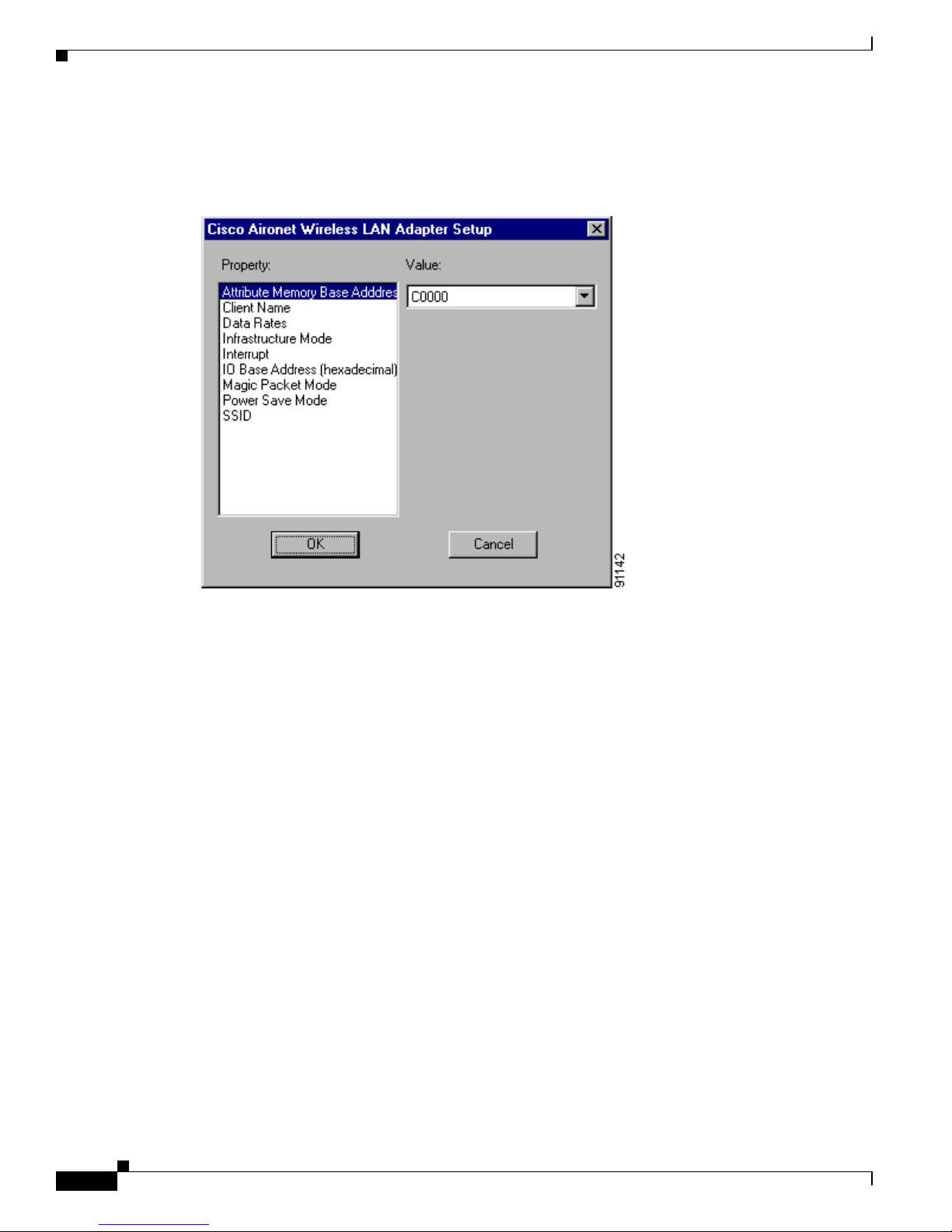
3-20
Cisco Aironet 340, 350, and CB20A Wireless LAN Client Adapters Installation and Configuration Guide for Windows
OL-1394-07
Chapter 3 Installing the Client Adapter
Installing or Upgrading the Client Adapter Softwa re
Step 20 The wizard starts to copy files, and the Cisco Aironet Wireless LAN Adapter Setup screen appears (see
Figure 3-6).
Figure 3-6 Cisco Aironet Wireless LAN Adapter Setup Screen
Step 21 If you are installing a PC or L M car d, se lect Interrupt in the Property list and an unused interrupt (from
Step 9) in the Value field and click OK. If you are inst alli ng a PCI or mi ni PCI c ard, cl ick OK.
Step 22 Messages appear as binding configurations are stored. Then the Microsoft TCP/IP Properties screen
appears (see Figure 3-7).
Page 55

3-21
Cisco Aironet 340, 350, and CB20A Wireless LAN Client Adapters Installation and Configuration Guide for Windows
OL-1394-07
Chapter 3 Insta lling the Client Adapter
Installing or Upgrading the Client Adapter Software
Figure 3-7 Microsoft TCP/IP Properties Screen
Step 23 On the IP Address tab, find and select the cli ent adap ter that you are inst alling un der Adap ter.
Step 24 Perform one of the following:
• If your computer is co nnected to a DHCP serv er , select Obtain an IP address from a DHCP server.
When asked if you want to enable DHCP, click Yes and OK.
• If your computer is not co nnec ted t o a DHC P server and you plan t o use TC P/IP, select Specify an
IP address and enter the IP ad dress, su bnet mask , an d defa ult gateway addre ss o f your c omput er
(which can be obtained fr om your syste m admini strator) . Click OK.
The installat ion pro cess b egins , an d y ou ar e no tified as ea ch com pon en t i s inst al led.
Step 25 Windows NT must be reboote d in orde r for your c hange s to ta ke effect. Click Yes when a message
appears asking if you wish to re boot now.
Caution To prevent unpredictable results, Cisco recommends that you click Yes to reboot your computer now.
Page 56

3-22
Cisco Aironet 340, 350, and CB20A Wireless LAN Client Adapters Installation and Configuration Guide for Windows
OL-1394-07
Chapter 3 Installing the Client Adapter
Verifying Installation
Step 26 If you want to install a second c lient a da pt er, allow your computer to completely reboot; th en r epeat th e
steps in this section for the second adapter.
Note In Step 13, find the Ins tal l Wizard files usin g Windows Explore r. Then double-c lick the
IWSetup.exe file.
Step 27 Go to the “Veri fying Installation” section belo w to determi ne if the instal lation was succe ssful. After you
verify installation, go to Chapter 4 if you want to create profiles for your client ada pter.
Verifying Installation
To verify that you have properly instal led th e clie nt adapt er so ftware, ch eck t he client adap ter’s LEDs.
If the installation was successful, the client adapter’s green LED blinks.
Note If your installat ion was unsu cce ssful or yo u experienc e d prob lem s d uring o r aft er inst alla tio n, re fer to
Chapter 10 for a list of instal latio n e rror m essages a nd tro ublesho ot ing infor mati on.
Now that your client adapter is properly installed, you are ready to go to Chapter 4 to create profiles for
your client adapt er, unless you are runn ing Windows XP or have more than one client ada pter inst all ed.
• If you are running Windows XP, g o to the “Deciding How to Configure Your Client Adapter
(Windows XP Only)” section below.
• If you have more than one client adapter installed, go to the “Selecting Among Several Installed
Client Adapters” section on page 3-24.
Deciding How to Configure Your Client Adapter
(Windows XP Only)
Windo ws XP is the only operating system th at enables you to configure your client adapte r without using
ACU. Therefore, if your compute r is run ning Windows XP, you must decide whether to con figure you r
client adapter throu gh Windows XP or ACU. To hel p you with you r decisi on, Table 3-3 co mpar es the
Windows XP and ACU client adapter features.
Table 3-3 Comparison of Windows XP and ACU Client Adapter Features
Feature Windows XP ACU
Configuration parameters Limited Extensive
Capabilities
Create profiles No Yes
Upgrade radio firmware No Yes
Restart client adapter without
rebooting or ej ecti ng c ard
No Yes
Turn radio on or off No Ye s
Page 57

3-23
Cisco Aironet 340, 350, and CB20A Wireless LAN Client Adapters Installation and Configuration Guide for Windows
OL-1394-07
Chapter 3 Insta lling the Client Adapter
Deciding How to Configure Your Client Adapter (Windows XP Only)
Perform one of the following:
• If you are planning to configure your c li ent a dapt er t hrough ACU instead of t hrough Windows XP,
follow the step s be low:
a. D oub le-cl ick My Computer, Control Panel, and Network Connections.
b. Ri ght-cli ck Wireless Netwo rk Connection and click Prop er tie s.
c. Select the Wireless Networks tab and uncheck the Use Windows to configure my wireless
network settings check box.
d. Follow the instructions in Chapter 4 and Chapter 5 to configur e your cli ent adap ter throu gh
ACU.
• If you are planning to configure your client ad apt er th rou gh Windows XP instead of through ACU,
go to Appendix E and follow the instructions there.
• If you are planning to configure your client adapter through Windows XP but you want to use ACU’s
diagnostic tools, go to Appendix E to configure the adapter through Windows XP; then follow the
instructions in Chapter 7 to use ACU’s diagnostic tools.
Security
Static WEP Yes Yes
LEAP authentication with dynamic
WEP
No Yes
Host-based EAP authentic ation with
dynamic WEP
Yes Yes
Diagnostics
Status screen Limited Extensive
Statistics screen (tr ans m it & re ce ive) No Yes
Site survey tool No Yes
RF link test tool No Ye s
Link status meter (graphical display) No Yes
Table 3-3 Comparison of Windows XP and ACU Client Adapter Features (continued)
Feature Windows XP ACU
Page 58
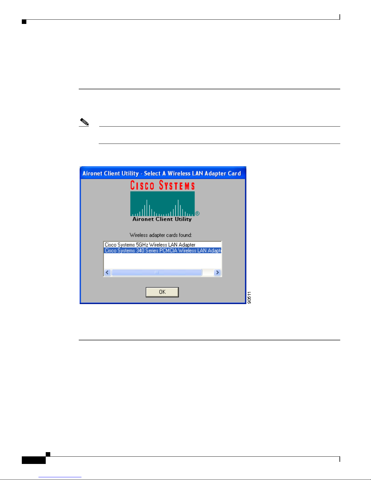
3-24
Cisco Aironet 340, 350, and CB20A Wireless LAN Client Adapters Installation and Configuration Guide for Windows
OL-1394-07
Chapter 3 Installing the Client Adapter
Selecting Among Several In stalled Client Adapters
Selecting Among Several Installed Client Adapters
If more than one client adapter is instal led in your compu ter , follo w the instru ctions belo w to specif y the
one for which you want to set up profiles in ACU.
Step 1 Double-click the Aironet Client Utility (ACU) icon on your desktop or double-click My Computer >
Control Panel > Airo net Client Utilit y to open ACU. The Select A Wirele ss LAN Adapt er Card scree n
appears (see Figure 3-8).
Note The Select A Wir ele ss L AN Adap ter Car d scree n appea rs wh en you star t ACU if more than one
card is inserted in your computer or no cards are inserted but more than one card is installed.
Figure 3-8 Select A Wireless LAN Adapter Card Screen
Step 2
Select the card you wish to configure from the list of available cards and click OK.
Step 3 Go to Chapter 4 to create profiles for this card.
Page 59

CHAPTER
4-1
Cisco Aironet 340, 350, and CB20A Wireless LAN Client Adapters Installation and Configuration Guide for Windows
OL-1394-07
4
Using the Profile Manager
This chapter explains how to use ACU’s profile manager feature to create and manage profiles for your
client adapter.
The following topics are covered in this chapter:
• Overview of Profile Manager, page 4-2
• Opening Profile Manager, page 4-2
• Creating a New Profile, page 4-3
• Including a Profile i n Au to Profile Se lect ion, p age 4-4
• Selecting the Active Profile, page 4-6
• Modifying a Profile, page 4-7
• Importing and Expo rt ing Pro files, page 4- 9
• Granting or Denying Access to Non-Ad minist rative Users, page 4-10
Page 60

4-2
Cisco Aironet 340, 350, and CB20A Wireless LAN Client Adapters Installation and Configuration Guide for Windows
OL-1394-07
Chapter 4 Using the Profile Manager
Overview of Profile Manager
Overview of Profile Manager
ACU’s profile manager fea ture al lows you to c re at e an d m a nage up to 16 profiles (or saved
configurations) fo r your client adapter. These profiles enable you to use your client adapter in different
locations, each of which requires different configuration settings. For example, you may want to set up
profiles for using your client adapter at the office, at home, and in public areas such as airports. Once
the profiles are cr e ated, yo u c an e a sily swi tch b etwee n the m witho ut h aving to r e con figure your c li ent
adapter each time you enter a new location.
Profiles are sto red in the pa rt of th e re gistr y reser v ed for th e cli ent adap ter driver and, therefore, are tied
to radio type. C onsequ en tly, if you set up p rofiles fo r a 340 seri es PC c ard a nd lat er up gra de t o a 3 50
series PC card, all of the profiles will be lost. Similarly, all profiles are lost if you uninstall the client
adapter’s software component s. To prevent your profiles from becoming lost, Cisco recommend s that
you back up your profiles using the pro file manager’s import/export feature. See the “Importing and
Exporting Profiles” se ct ion o n page 4-9 for details.
Opening Profile Manager
To op en ACU’s profile manager, double-click t he Aironet Client Utility (ACU) icon o n y our d esk top
or double-click My Computer > Control Panel > Aironet Client Utility to open ACU. Then click the
Profile Manager icon or select Profile Manager from the Commands dro p-d own menu. T he Profile
Manager screen appears (se e Figure 4-1).
Figure 4-1 Profile Manager Screen
Page 61

4-3
Cisco Aironet 340, 350, and CB20A Wireless LAN Client Adapters Installation and Configuration Guide for Windows
OL-1394-07
Chapter 4 Using the Profile Manager
Creating a New Profile
Profile manager allows you to perform the following tasks rela ted to the ma nagement of profiles:
• Create a new profile, see below
• Include a profile in auto profile selection, page 4-4
• Select the active profile, page 4-6
• Edit a profile, page 4-7
• Set a profile to default values, page 4-8
• Rename a profile, page 4-8
• Delete a profile, page 4-8
• Import a profile, page 4-9
• Export a profile, page 4-9
Follow the instructions on the page indicated for the task you want to perform.
Note If your system administrator used an administrative tool to deactivate certain parameters, these
parameters are disab led on the Profile Ma nager scr een and ca nnot be sele cted.
Creating a New Profile
Follow the steps below to create a new profile.
Step 1 Click Add on the Profile Manager scree n. A c urs or ap pe ar s in the Pro file Ma nage ment edi t b ox.
Step 2 Enter the name for your new profile (for example, Office, Home, et c.).
Step 3 Press Enter. The Properties screens a ppear wit h the name of your new profile in parenthe ses.
Step 4 Perform one of the following:
• If you want this profile to use the defa ult va lues, clic k OK. The profile is added to the list of profiles
on the Profile Manager scree n.
• If you want to cha ng e any of t h e co nfigur ation pa rame te r s ett ings, fol low the i n struc tions in
Chapter 5. The profile is added to the list of profiles on the Profile Manager screen.
Step 5 Click OK or Apply to save your profile.
Note The profiles for PC-Cardbus cards are tied to the slot in which the card is inserted. Therefore,
you must always insert your PC-C ar dbus card i nto the same slo t, c rea te pro files for bo th slot s,
or export the profiles fr om on e slot and i mp ort them f or the oth er sl ot.
Page 62
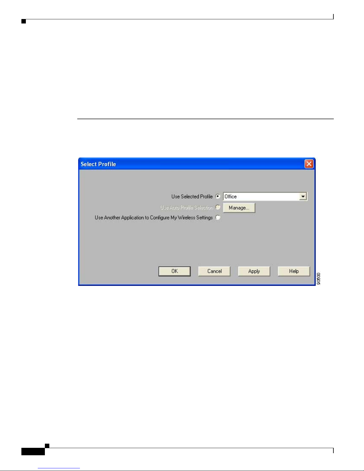
4-4
Cisco Aironet 340, 350, and CB20A Wireless LAN Client Adapters Installation and Configuration Guide for Windows
OL-1394-07
Chapter 4 Using the Profile Manager
Including a Profile in Auto Profile Selection
Including a Profile in Auto Profile Selection
After you have created profiles for your client adapter, you can choose to include them in the profile
manager’s auto profile selection feature. Then when auto profile selection is enabled, the client adapter
automatically selects a profile from the list of profiles that were included in auto profile selection and
uses it to establish a connection to the network.
Follow the steps belo w to include an y of your prof iles in auto prof ile sele ction and to establish the order
in which the profiles will be selected for use.
Step 1 Open ACU; click the Select Profile icon or select Select Profile from the Commands drop-down menu.
The Select Profile screen appears (see Figure 4-2).
Figure 4-2 Select Profile Screen
Step 2 Click the Manage button next to the Use Auto Profile Selection option. The Auto Profile Selection
Management screen appea rs (see Figure 4-3).
Page 63

4-5
Cisco Aironet 340, 350, and CB20A Wireless LAN Client Adapters Installation and Configuration Guide for Windows
OL-1394-07
Chapter 4 Using the Profile Manager
Including a Profile in Auto Profile Selection
Figure 4-3 Auto Profile Selection Management Screen
Step 3 All the prof iles that you created are listed in the Available Profiles box. Highlight e ach one that you want
to include in auto profile selection and click the Add button. The profiles move to the Auto Selected
Profiles box.
The following rules apply to auto profile selection:
• You must include at least two profiles in the Auto Selected Profiles Box.
• The profiles must specify an SSID; otherwise, they cannot be selected in the Available Profiles
box.
• Profiles cannot specify multiple SSIDs; otherwise, they cannot be selected in the Available
Profiles box.
• Each profile that is included in auto profile selection must have a unique SSID. For example,
if Profile A and Profile B both have “ABCD” as their SSID, only Profile A or Profile B can be
included in auto profile selection.
Note If you ev er w ant to remo v e a prof ile f rom auto profile selection, highlight the profile in th e Auto
Selected Profiles box and click the Remove button. The profile moves to the Available Profiles
box.
Page 64

4-6
Cisco Aironet 340, 350, and CB20A Wireless LAN Client Adapters Installation and Configuration Guide for Windows
OL-1394-07
Chapter 4 Using the Profile Manager
Selecting the Active Profile
Step 4 The first profile in the Auto Selec ted Profiles box has t h e hi gh est prior ity whil e t he l ast profile has t he
lowest priority. To c hange the order (and priority) of y our auto-selectable profiles, highlight the profile
that you want to move and click the High Pri ority or Low Prior ity arrow to move the profile up or
down, respectively.
When auto profile selection is enabled , the client adapter scans for an a vailable network. The profile with
the highest priority and the same SSID as one of the found networks is the one that is used to connect to
the network. If the co nnec tio n f ai ls, the client adapter tries th e next highest priority prof ile th at m at ches
the SSID and so on.
Step 5 Click OK to save your changes.
Selecting the Active Profile
Follow the steps below to specify the profile that the client adapter is to use.
Note Because EAP-TLS, PEAP, and EAP-SIM authentication are enabled in the operating system and not in
ACU, you cannot switch between these authentication types simply by switching profiles in ACU. You
can create a profile in ACU that uses host-based EAP, but you must enable the specific authentication
type in Windows (provided Windows is using the Mi cr osoft 80 2.1X sup pli cant ). I n ad ditio n, Windows
can be set for only one aut hentication typ e at a time; therefore, if you hav e more than one pro file in ACU
that uses host-based EAP and you wan t to use another authenticat ion type, yo u must chang e
authentication types in Windows after switching profiles in ACU.
Note You can u se ACM instea d of ACU’s Profile Manager to select the active profile. Refer to Chapter 8 for
instructions.
Step 1 Open ACU; click the Select Profile icon or select Select Profile from the Commands drop-down menu.
The Select Profile screen appears (see Figure 4-2).
Step 2 Select one of the following options:
• Use Selected Profile—This option enables you to select one profile for the client adapter to use. If
you choose this option, y ou also must sel ect t h e de sire d p rofile fr om t he d rop -down box.
If the client adapter ca nnot as socia te to an access po int or lo ses ass ociatio n while us ing th e sele cted
profile, th e adapter does no t attempt to asso ciate usin g anoth er prof ile. To associate, you must selec t
a different profile or select Use Auto Profile Selection.
Note If no profiles have been set for your client adapter, the Use Selected Profile drop-down box
is disabled but displays “Driver Advanced Tab Settings.”
Page 65

4-7
Cisco Aironet 340, 350, and CB20A Wireless LAN Client Adapters Installation and Configuration Guide for Windows
OL-1394-07
Chapter 4 Using the Profile Manager
Modifying a Profile
• Use Auto Profile Selection—This option causes the client adapter’s driver to automatically select
a profile from the list of profiles that wer e set up to be inc luded in auto profile selecti on.
If the client adapter loses association for more than 10 seconds (or for more than the time specified
by the LEAP authentication timeout value on the LEAP Settings screen if LEAP is enabled), the
driver sw itches automatically to anothe r profile that is incl uded in auto prof ile selection. The adapte r
will not switch prof ile s as long as it remains ass ociat ed or reas soci ates w ithin 10 seconds ( or wit hin
the time specifi ed by the LEAP aut hentication timeo ut value). To force the client adapter to associate
to a different access point, you must select a new profile using the Use Selected Profile option.
Note This option is available only if two or more profiles are included in auto profile selection.
Note Login scripts are n ot r elia ble i f you use auto pr ofile sele c tion w it h LEAP. If you LEAP
authenticate and achie v e full netwo rk connecti vity before or at the same time as y ou log into
the computer , the login scrip ts will run. Ho we ver, if you LEAP authenticate and achiev e full
network connectivity after you log into the computer, the login scripts will not run.
• Use Another Application to Conf igure My W ireless Set tings—This option enables an a pplication
other than ACU to conf igure the client adapter. Examples of such applications include Wi ndo ws XP
and Boingo.
Note You must s el ect this option if you are configuring your card through Windows XP but want
to use ACU’s diagnostic tools. Refer to Appendix E for information on configuring your
client adapter throu gh Windows XP.
Step 3 Click OK or Apply to save your selection. The client adapte r sta rts u sin g a p rofile ba sed on t he opt ion
selected above.
Modifying a Profile
This section provides instructions for modifying an existing profile. Follow the steps in the
corresponding s ect ion below to e dit , se t t o default values, rena me, or d elet e a pr ofile.
Editing a Profile
Step 1 Open ACU; click the Profile Manager icon or select Profile Manager from the Commands drop-down
menu. The Profile Manager scre en appea rs (see Figur e 4- 1).
Step 2 From the Profile Management drop-down box, select the profile that you want to edit.
Step 3 Click Edit. The Properties screens ap pe ar w it h th e name o f th e pro file in pa rent hese s.
Step 4 Follow the instructions in Chapter 5 to change any of the configuration parameters for this profile.
Step 5 Click OK or Apply to save your configuration change s.
Page 66

4-8
Cisco Aironet 340, 350, and CB20A Wireless LAN Client Adapters Installation and Configuration Guide for Windows
OL-1394-07
Chapter 4 Using the Profile Manager
Modifying a Profile
Setting a Profile to Default Values
Step 1 Open ACU; click the Profile Manager icon or select Profile Manager from the Commands drop-down
menu. The Profile Manager scre en appea rs (see Figur e 4- 1).
Step 2 From the Profile Management drop-down box, select the profile that you want to set to default values.
Step 3 Click Use Defaults.
Step 4 When prompted, click Yes to confirm your decision.
Step 5 Click OK or Apply to save your change. The profile is saved with default values.
Renaming a Profile
Step 1 Open ACU; click the Profile Manager icon or select Profile Manager from the Commands drop-down
menu. The Profile Manager scre en appea rs (see Figur e 4- 1).
Step 2 From the Profile Management drop-down box, select the profile that you want to rename.
Step 3 Click Rename. The Profile Management edit box becomes en abled .
Step 4 Enter a new name for th e pro file.
Step 5 Click OK or Apply to save your change. The profile is renam ed and adde d to the list of pr ofiles.
Deleting a Profile
Step 1 Open ACU; click the Profile Manager icon or select Profile Manager from the Commands drop-down
menu. The Profile Manager scre en appea rs (see Figur e 4- 1).
Step 2 From the Profile Management drop-down box, select the profile that you want to delete.
Step 3 Click Delete.
Step 4 When prompted, click Yes to confirm your decision.
Step 5 Click OK or Apply to save your change. The profile is deleted.
Page 67

4-9
Cisco Aironet 340, 350, and CB20A Wireless LAN Client Adapters Installation and Configuration Guide for Windows
OL-1394-07
Chapter 4 Using the Profile Manager
Importing and Exporting Profiles
Importing and Exporting Profiles
This section provide s instruc ti ons for i mpor t ing a nd expo rt ing pro files. You may want to use the
import/export feature for the following reasons:
• To back up profiles before changing c lient ada pter type s or uninstal ling cli ent adapt er software
components
• T o export profiles for a PC-Cardbus card in one Cardbus slot and import them for use with a second
Cardbus slot
• To set up your computer with a profile from an other co mputer
• To export one of your profiles and use it to set up additiona l com puters
Follow the steps in the co rrespo nding se ctio n b elow to im por t or export pr ofiles.
Importing a Profile
Step 1 If the profile that you want to import is on a floppy disk, insert the disk into your computer’s floppy drive.
Step 2 Open ACU; click the Profile Manager icon or select Profile Manager from the Commands drop-down
menu. The Profile Manager scre en appea rs (see Figur e 4- 1).
Step 3 Click Import. The Import Profile screen appears.
Step 4 Find the directory where the profile is located.
Step 5 Click the profile so it appears in the File name box at the bottom of the Import Profile screen.
Step 6 Click Open. The imported profile appears in the list of profiles on the Profile Manager screen.
Exporting a Profile
Step 1 Insert a blank floppy disk int o your co mpu ter ’s floppy drive, if you wi sh to expo rt a pr ofile to a flo ppy
disk.
Step 2 Open ACU; click the Profile Manager icon or select Profile Manager from the Commands drop-down
menu. The Profile Manager scre en appea rs (see Figur e 4- 1).
Step 3 From the Profile Management drop-down box, select the profile that you want to export.
Step 4 Click Export. The Save Profile As screen appears. The default filename is ProfileName.pro, where
ProfileName is the name of the selected profile, and the default directory is the directory in which ACU
is installed.
Step 5 If you want to change the profile name, enter a new name in the File name edit box.
Step 6 Select a di ff erent dire ctory (for e xample , your comput er’s floppy disk drive or a location on the network)
from the Save in drop-down box.
Step 7 Click Save. The profile is exported to the specified location.
Step 8 Follow the instructions in the “Importing a Profile” section t o import the profile on another co mputer.
Page 68

4-10
Cisco Aironet 340, 350, and CB20A Wireless LAN Client Adapters Installation and Configuration Guide for Windows
OL-1394-07
Chapter 4 Using the Profile Manager
Granting or Denying A c cess to Non-Admin istrative Users
Granting or Denying Access to Non-Administrative Users
If you used the Install W izard to perform a custom instal lati on, you were able to specify the v alu e of the
Allow Non-Administrator Users to Save Settings to the Registry parameter. When this parameter is set
to Yes, it enables users without administrative rights to modify profiles in ACU and save them to the
registry on computers running Windows NT, 2000, or XP. (This option is not available for Windows 98,
98 SE, and Me because these versions of Windows do not support different classes of users.) When this
parameter is set to No, access to non- administ rative users is denied.
ACU has a similar parameter that you can use to change the selec tion you made during ins tallati on,
provided you hav e administrati ve right s. Follo w the steps belo w if you want to change the cur rent setting
of this parameter.
Step 1 Open ACU.
Step 2 Click the Preferences icon or select Preferences from the Options drop-down menu. The Aironet Client
Utility Preferences screen appears (see Figure 4-4).
Figure 4-4 Aironet Client Utility Preferences Screen
Page 69

4-11
Cisco Aironet 340, 350, and CB20A Wireless LAN Client Adapters Installation and Configuration Guide for Windows
OL-1394-07
Chapter 4 Using the Profile Manager
Granting or Denying A ccess to No n-Administrative User s
Step 3 Perform one of the following:
• Check the Allow Non- Administrator User s to Sav e Pro files to the Registr y check box if you want
to allow regular-class users to modify and save profiles.
• Uncheck the Allow Non-Administrator Users to Save Profiles to the Registry check box if you
want to prevent regular-class users fr om m odi fyi ng and saving pro files.
Step 4 Click OK to save your changes.
Page 70

4-12
Cisco Aironet 340, 350, and CB20A Wireless LAN Client Adapters Installation and Configuration Guide for Windows
OL-1394-07
Chapter 4 Using the Profile Manager
Granting or Denying A c cess to Non-Admin istrative Users
Page 71

CHAPTER
5-1
Cisco Aironet 340, 350, and CB20A Wireless LAN Client Adapters Installation and Configuration Guide for Windows
OL-1394-07
5
Configuring the Client Adapter
This chapter explains how to set the configuration parameters for a specific profile.
The following topics are covered in this chapter:
• Overview, page 5-2
• Setting System Parameters, page 5-3
• Setting RF Network Parameters, page 5-7
• Setting Advanced Infrastructure Parameters, page 5-14
• Setting Advanced Ad Hoc Parameters, page 5-17
• Setting Network Security Parameters, page 5-21
Page 72

5-2
Cisco Aironet 340, 350, and CB20A Wireless LAN Client Adapters Installation and Configuration Guide for Windows
OL-1394-07
Chapter 5 Configuring the Client Adapter
Overview
Overview
When you choose to create a new profile or edit an existing profile on the Profile Manager screen, the
Properties screens appear with the name of your profile in parentheses. These screens enable you to set
the configuration parameters for that profile.
Note If you do not chang e any o f th e configur ation pa r amet ers, the d efaul t values a re us ed .
Note If you are planning to set parameters on more than one of the Properties screens, wait until you are
finished with all of the screens before clicking OK. When you click OK, you are returned to the Profile
Manager screen.
Each of the Properties scr eens (listed belo w) contains p arameters that af fect a specif ic aspect of the c lient
adapter:
• System Param eter s—Prepares the client adapte r for us e in a wir eles s netwo rk
• RF Network—Controls how the client adapter transmits and re ceives data
• Advanced (Infrastructure)—Controls how the client adapter operates within an infrastructure
network
• Advanced (Ad Hoc)—Controls how the client adapter operates within an ad hoc (peer-to-peer)
network
• Network Security—Controls ho w a client adapt er associates to an access point, authenticates to the
wireless network, and enc rypt s and de crypt s da ta
Table 5-1 enables you to quickly locate the instructions for setting each Properties screen’s parameters.
Table 5-1 Locating Configuration Instructions
Parameter Category Page Number
System page 5-3
RF network page 5-7
Advanced infrastructure page 5-14
Advanced ad hoc page 5-17
Network security page 5-21
Page 73
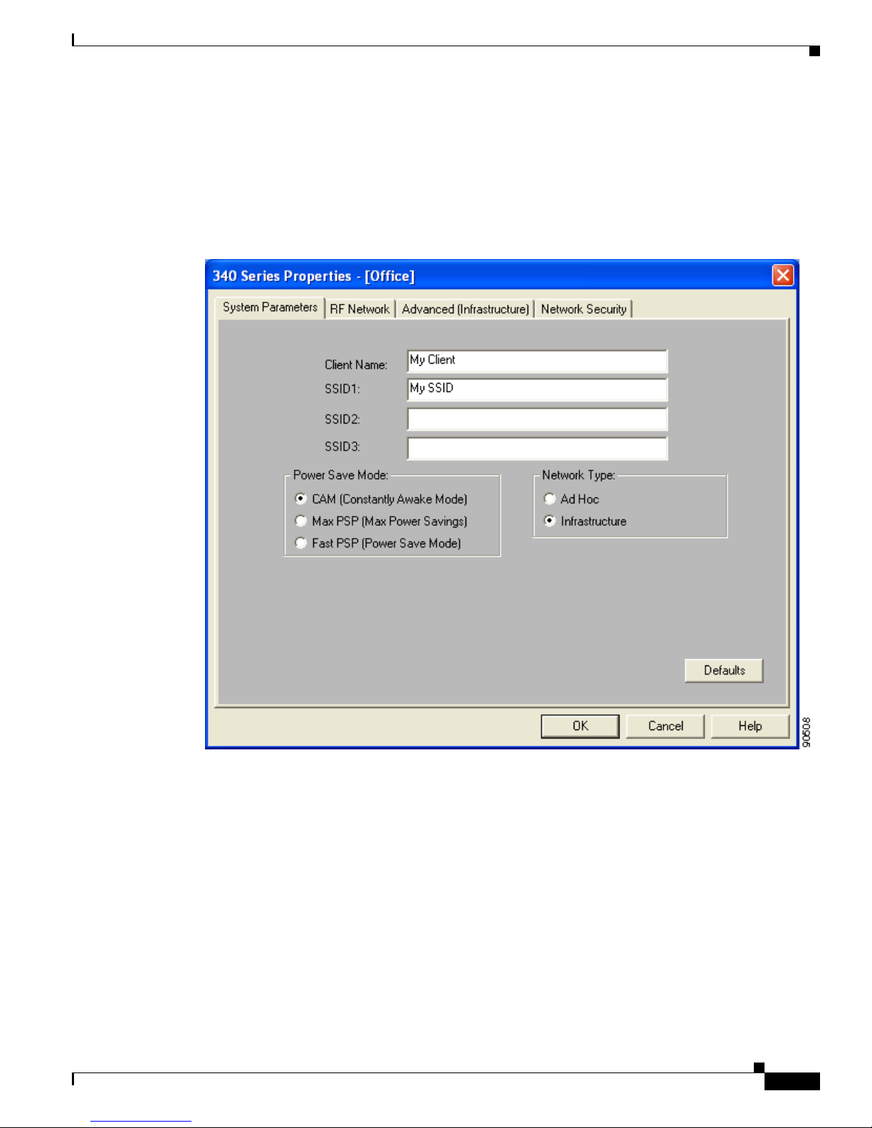
5-3
Cisco Aironet 340, 350, and CB20A Wireless LAN Client Adapters Installation and Configuration Guide for Windows
OL-1394-07
Chapter 5 Configuri ng the Client Adapter
Setting System Parameters
Setting System Parameters
The System Parameters screen (see Figure 5-1) enables you to set parameters that prepare the client
adapter for use in a wireless network. This screen appears after you create and save a new profile or click
Edit on the Profile Manager screen.
Figure 5-1 System Parameters Screen
Table 5-2 lists and describes the client adapter’s system parameters. Follow the instructions in the table
to change any parameters.
Page 74

5-4
Cisco Aironet 340, 350, and CB20A Wireless LAN Client Adapters Installation and Configuration Guide for Windows
OL-1394-07
Chapter 5 Configuring the Client Adapter
Setting System Parameters
Table 5-2 Syste m Pa ramete r s
Parameter Description
Client Name A logical name for your workstation. It allows an admi nistrat or to
determine which devices are connected to the access point without
having to memorize every MAC address. This name is included in the
access point’s list of connected devices.
Range: You can key in up to 16 ASCII characters
Default: A blank field
Note Each compute r on the network should have a unique clie nt
name.
SSID1 The service set identifier (SSID) identifies the specific wireless
network that you want to access.
Range: You ca n key in up to 32 ASC II char acte rs (cas e sens itive)
Default: A blank field
Note If you leave this par amete r blank, your client adap ter can
associate to any access point on the network t ha t is co nfigured
to allow broadcast SSIDs (see the AP Radio Hardware page in
the access point management system). If the acces s point with
which the clien t ad ap ter is t o co mm uni cate is not conf igured to
allow broadcast SSIDs , the value of this parameter must match
the SSID of the access point. Otherwise, the client adapter is
unable to access the network.
SSID2 An optional SSID that identifies a second distin ct network and enables
you to roam to that network with out having to reco nfigure your cl ient
adapter.
Range: You ca n key in up to 32 ASC II char acte rs (cas e sens itive)
Default: A blank field
Note If a profile specifies more than one SSID, it cannot be included
in auto profile selection.
Note This field is un available for any profiles that are i nclude d in
auto profile selection.
SSID3 An optional SSID that identifies a third distinct network and enables
you to roam to that network with out having to reco nfigure your cl ient
adapter.
Range: You ca n key in up to 32 ASC II char acte rs (cas e sens itive)
Default: A blank field
Note If a profile specifies more than one SSID, it cannot be included
in auto profile selection.
Note This field is un available for any profiles that are i nclude d in
auto profile selection.
Page 75

5-5
Cisco Aironet 340, 350, and CB20A Wireless LAN Client Adapters Installation and Configuration Guide for Windows
OL-1394-07
Chapter 5 Configuri ng the Client Adapter
Setting System Parameters
Power Save Mode Sets your client adapter to its optimum power consumpt ion settin g.
Options: CAM, Max PSP, or Fast PSP
Default: CAM (Constantly Awake Mode)
Power Save Mode Description
CAM (Constantly Awake
Mode)
Keeps the client adapter powered up
continuously so there is little lag in
message response time.
Consumes the most power but offers the
highest throughput. Is r ecom me nded f or
desktop computers a nd devices t hat use
AC p o we r.
Max PSP (Max Power
Savings)
Causes the access point to buffer incoming
messages for the client adapter, which
wakes up periodically and polls the access
point to see if any buffered messages are
waiting for it. The adapter can request
each message an d t h en go bac k t o s le ep .
Conserves the most power but offers the
lowest throughput. Is recomm ended for
devices for which power consumption is
the ultimate concern (such as small
battery-powered devices).
Note When you set Max PSP mode and
close ACU, th e follo wing message
appears the next tim e yo u o pe n
ACU: “Maximum Power Save
Mode will be temporarily disabl ed
while you are running this
application.” While ACU is open,
Fast PSP mode is active. When
you close ACU, the card returns to
Max PSP mode.
Fast PSP (Power Save
Mode)
Switches between PSP mode and CAM
mode, depending on ne twork tra ffic. This
mode switches to CAM when retrieving a
large number of packets and switches back
to PSP after the packets have been
retrieved.
Is recommended when power consumption
is a concern but you need greater
throughput than tha t all owed by Max PSP.
Table 5-2 System Parameters (continued)
Parameter Description
Page 76

5-6
Cisco Aironet 340, 350, and CB20A Wireless LAN Client Adapters Installation and Configuration Guide for Windows
OL-1394-07
Chapter 5 Configuring the Client Adapter
Setting System Parameters
Go to the next section to set additional parameters or click OK to return to the Profile Manager screen.
On the Profile Manager screen, click OK or Apply to save your changes.
Network Type Specifies the type of network in which your client adapter is installed.
Options: Ad Hoc or Infrastructure
Default: Infrastructure
Network Type Description
Ad Hoc Often referred to as peer to peer. Indicates
that your wirele ss n etwork c on sis ts of a
few wireless devices that ar e not
connected to a wired Eth erne t network
through an access point. For example, an
ad hoc network can be set up betwe en
computers in a conference room so users
can share information in a meeting.
Infrastructure Indicates that your wireless network is
connected to a wired Eth erne t network
through an access point.
Table 5-2 System Parameters (continued)
Parameter Description
Page 77

5-7
Cisco Aironet 340, 350, and CB20A Wireless LAN Client Adapters Installation and Configuration Guide for Windows
OL-1394-07
Chapter 5 Configuri ng the Client Adapter
Setting RF Network Parameters
Setting RF Network Parameters
The RF Network screen (see Figure 5-2) enables you to set pa rameter s that contr ol how and when th e
client adapter transmits and receives data. To access this screen, select the RF Network tab fr om the
Properties screens.
Figure 5-2 RF Network Screen
Page 78

5-8
Cisco Aironet 340, 350, and CB20A Wireless LAN Client Adapters Installation and Configuration Guide for Windows
OL-1394-07
Chapter 5 Configuring the Client Adapter
Setting RF Network Parameters
Table 5-3 lists and describes the client adapter’s RF network parameters. Follow the instructions in the
table to change any parameters.
Table 5-3 RF Network Parameters
Parameter Description
Data Rate Specifies the rate at which your client adapter should transmit or
receive packets to or from access points (in infrast ructur e mode) or
other clients (in a d hoc m ode).
Auto Rate Selection is recommended for infrastruc ture mode; setting a
specific data rate is recommended for ad hoc mode.
Options: Auto Rate Selection, 1 M bps O nly, 2 Mbps Only, 5.5 Mbps
Only, or 11 Mbps Only (2.4-GHz client adapters) ;
Auto Rate Selection, 6 Mb ps Only, 9 Mbps Only, 12 Mbps
Only, 18 Mbps Only, 24 Mbps Only, 36 Mbps Only, 48 Mbps
Only, or 54 Mbps Only (5 -GH z cl ient adap ter s)
Default: Auto Rate Selection
Data Rate
Description
2.4-GHz Client
Adapters
5-GHz Client
Adapters
Auto Rate
Selection
Auto Rate
Selection
Uses the 11-Mbps (for 2.4-G Hz client
adapters) or 54-Mbps (for 5-GHz client
adapters) data rate when possible but
drops to lower rates when necessary.
1 Mbps
Only
6 Mbps
Only
Offers the greatest range but the lowest
throughput.
2 Mbps
Only and
5.5 Mbps
Only
9 Mbps
Only to 4 8
Mbps Only
Progressively offers less range but greater
throughput than the 1 Mbps Only (fo r
2.4-GHz client a dapt ers) or 6 Mbps On ly
(for 5-GHz client adapt ers) op tion.
11 Mbps
Only
54 Mbps
Only
Offers the greatest throughput but the
lowest range .
Note Your client adapter’s data rate must be set to Auto Rate
Selection or must match the data rate of the access point (in
infrastructure mode) or the other clients (in ad hoc mode) with
which it is to c ommunicate. Ot herwise, your c lient adap ter may
not be able to associate to them.
Page 79

5-9
Cisco Aironet 340, 350, and CB20A Wireless LAN Client Adapters Installation and Configuration Guide for Windows
OL-1394-07
Chapter 5 Configuri ng the Client Adapter
Setting RF Network Parameters
Use Short Radio Hea ders Checking this check box sets you r c li ent a da pter t o use s hor t ra dio
headers. However, the adapter can use short radio headers only if the
access point is also configured to support them and is using them. If any
clients associated to an access point are using long headers, then all
clients in that cell must also use long headers, even if both this client
and the access point have short radio head ers enable d.
Short radio headers improve throu ghput per formanc e; long radio
headers ensure compatibility with clients and access points that do not
support short radio headers.
Default: Checked
Note This para me ter is available on ly fo r 2. 4-G Hz cl ient ad ap ters .
Note This pa rameter is referr ed to as Preambles on th e ac cess po int
screens.
World Mode Checking this check box enables the client adapter to adopt the
maximum transmit power level and the frequency range of the access
point to which it is associated, provided the access point is also
configured for world mode. This parameter is available only in
infrastructure mo de a nd is desi gn ed f or use rs w ho travel betw een
countries and want their client adapte rs to associ ate to acc ess points in
different regulatory domains.
Default: Unchecked
Note This para me ter is available on ly fo r 2. 4-G Hz cl ient ad ap ters .
Note When World Mode is enabled, the client adapter is limited to
the maximum transmit power level allowed by the country of
operation’s regulatory agency.
Scan For A Better Access
Point
Checking this check box causes the client to look for a better access
point if the signal strength of its associated access point is less than the
specified value after the specified time and to switch associations if it
finds one .
Example: If the default values of 20 seconds and 5 0% are used, the
client begins monitoring the strength of the signal received
from its associated acc es s p oint 2 0 se co nd s af ter be co ming
associated. The m on ito ring c ontinue s once pe r se co nd. I f
the client detects a signal strength reading below 50%, it
scans for a better access point.
Range: 5 to 255 seconds; 0 to 7 5% si gnal streng th
Defaults:Checked, 20 seconds, 50% signa l strength
Note The ability to specify the time and signal strength is available
in ACU version 6.1 or greate r, which is i ncl uded i n Instal l
Wizard version 1.1 or greater.
Table 5-3 RF Network Parameters (continued)
Parameter Description
Page 80

5-10
Cisco Aironet 340, 350, and CB20A Wireless LAN Client Adapters Installation and Configuration Guide for Windows
OL-1394-07
Chapter 5 Configuring the Client Adapter
Setting RF Network Parameters
Channel Specifies the frequency that your client adapter will use as the channel
for communicat ions. Th ese ch an ne ls c onf orm t o the I EEE 802 .1 1
Standard for your regul at ory do ma in.
• In infrastructure mode, this parameter is set automatically and
cannot be changed. The client adapter listens to the entire
spectrum, selects th e best acce ss poin t to asso ciate to , an d uses th e
same frequency as tha t a c cess point.
• In ad hoc mode, the channel of the client adapter must be set to
match the channel used by the other clients in the wireless network.
If the client adapter do es not find any other ad hoc adapt ers, th is
parameter specifies the ch annel with which the adapter will star t its
cell.
Range: Dependent on client adap ter radi o and regulato ry domai n
Example for 2.4-GHz client a d apter s:
1 to 11 (2412 to 246 2 MHz ) in N or th A mer ica
Example for 5-GHz client adapter s:
36, 40, 44, 48, 52 , 56, 60 , an d 6 4 (51 80, 5 200, 5 220 , 524 0,
5260, 5280, 5300, and 5320 MHz ) in Nort h Ameri ca
Default: Dependent on client adap ter radi o and regulato ry domai n
Example for 2.4-GHz client adap ters:
6 (2437 MHz) in Nor th Am er ica
Example for 5-GHz client adapter s:
36 (5180 MHz) in North Amer ica
Note Refer to Appendix D for a list of channel identifiers, channel
center frequencies, and regulatory domains for each channel.
Table 5-3 RF Network Parameters (continued)
Parameter Description
Page 81

5-11
Cisco Aironet 340, 350, and CB20A Wireless LAN Client Adapters Installation and Configuration Guide for Windows
OL-1394-07
Chapter 5 Configuri ng the Client Adapter
Setting RF Network Parameters
Transmit Power Defines the power level at which your client adapter transmits. This
value must not be higher than that allowed by your country’s regulatory
agency (FCC in the U.S., DOC in Canada, ETSI in Europe, MKK in
Japan, etc.).
Options: Dependent on the power table programme d into the client
adapter; see the table below
Default: The maximum power level programmed into the cl ient
adapter and al lowed by yo ur coun try’s regulatory agency
Possible Power Levels Client Adapter Ty pe
30 mW or 1 mW 340 series PC cards
30 mW, 15 mW, 5 mW, or
1 mW
340 series LM cards a nd PCI ca rds
100 mW, 50 mW, 30 mW,
20 mW, 5 mW, or 1 mW
350 series client adap ters
20 mW, 10 mW, or 5 mW PC-Cardbus card
Note Reducing the transmit p ower level conserves battery p ower but
decreases radio ra ng e.
Note When World Mode is enabled, the client adapter is limited to
the maximum transmit power level allowed by the country of
operation’s regulatory agency.
Note If you are u si ng an ol der version o f a 340 or 3 50 seri es clie nt
adapter, your power level options may be different than those
listed he r e.
Table 5-3 RF Network Parameters (continued)
Parameter Description
Page 82

5-12
Cisco Aironet 340, 350, and CB20A Wireless LAN Client Adapters Installation and Configuration Guide for Windows
OL-1394-07
Chapter 5 Configuring the Client Adapter
Setting RF Network Parameters
Clear Channe l As se ssm en t Specifies the me t hod tha t d et e rmin es whether th e ch an ne l on w hi ch
your client adapter will op erate is clear prior to the tra nsmiss ion of
data.
Options: Firmware Default (XXX), Carrier/Corr elatio n (Car/Cor ),
Energy Detect (ED), or ED or Car/Co r
Default: Firmware Default (XXX)
Method Description
Firmware Default (XXX) The Clear Channel Assessment (CCA)
mechanism will report that the channel is
busy based on the default value of the
client adapter’s firm w are. T h e firmwa r e ’s
CCA default value is shown in
parentheses.
Note The CCA defau lt value for PCM ,
LMC, and PCI card firmware is
Car/Cor; the de fault v alue for min i
PCI card firmware is ED.
Carrier/Correlation
(Car/Cor)
The CCA mechanism will report that the
channel is busy upon detection o f a
direct-sequence spread spectrum (DSSS)
signal. T his signal may be ab ove or below
the ED thres hold .
Energy Detect (ED) The CCA mechanism will report that the
channel is busy upon detection o f any
energy above the ED threshold.
ED or Car/Cor The CCA mechanism will report that the
channel is busy upon detection of a DSSS
signal or any energy above the ED
threshold.
Note This para me ter is available on ly fo r 2. 4-G Hz cl ient ad ap ters .
Table 5-3 RF Network Parameters (continued)
Parameter Description
Page 83

5-13
Cisco Aironet 340, 350, and CB20A Wireless LAN Client Adapters Installation and Configuration Guide for Windows
OL-1394-07
Chapter 5 Configuri ng the Client Adapter
Setting RF Network Parameters
Go to the next section to set additional parameters or click OK to return to the Profile Manager screen.
On the Profile Manager screen, click OK or Apply to save your changes.
Data Retries Defines the number of times a packet is resen t if the initial transmission
is unsuccessful.
Range: 1 to 128
Default: 16 (2.4-GHz client ad apter s) or 32 (5-G Hz clie nt adapte rs)
Note If your ne twork protoc ol performs i ts own retries, set th is to a
smaller val ue than the de fa ult . This w ay notif i cati on of a “bad”
packet is sent up the protocol stack quickly so the application
can retransmit the pa cket if nec essa ry.
Fragment Threshold Defines the threshold above which an RF data packet is split up or
fragmented. If one of those fragmen ted packets experi ences
interference during transmission, only that specific packet would need
to be res en t.
Throughput is generally lower for fr agmented pack ets because the fixe d
packet overhead consumes a higher portion of t he RF bandwidt h.
Range: 256 to 2312
Default: 2312
Table 5-3 RF Network Parameters (continued)
Parameter Description
Page 84

5-14
Cisco Aironet 340, 350, and CB20A Wireless LAN Client Adapters Installation and Configuration Guide for Windows
OL-1394-07
Chapter 5 Configuring the Client Adapter
Setting Advanced Infrastructure Parameters
Setting Advanced Infrastructure Parameters
Note You can set advanced infr astruc ture par ameters on ly if your cl ient adapter ha s been set to
operate in an infrastructure network. See the Network Type parameter in Table 5-2.
The Advanced (Infrastructure) screen (see Figure 5-3) enables you to set parameters that control how the
client adapter operates within an infrastructure network. To access this screen, select the Advanced
(Infrastru ct ure) tab from the Properties screens.
Figure 5-3 Advanced (Infrastructure) Screen
Page 85

5-15
Cisco Aironet 340, 350, and CB20A Wireless LAN Client Adapters Installation and Configuration Guide for Windows
OL-1394-07
Chapter 5 Configuri ng the Client Adapter
Setting Advanced Infrastructure Parameters
Table 5-4 lists and describes the client adapter’s advanced infrastructure parameters. Follow the
instructions in the table to change any parameters.
Table 5-4 Advanced (Infrastructure) Parameters
Parameter Description
Antenna Mode (Receive) Specifies the antenna that your client adapter uses to receive data.
• PC card—The PC card’s integrated, permanently attached
antenna operates be st wh en used i n d iversity mode . D iversity
mode allows the card to use the better signal from its two antenna
ports.
Options: Diversity (Both), Primary Antenna Only, Secondary
Antenna On ly
Default: Diversity (Both)
• LM card—The LM card is shipped without an antenna; however,
an antenna can be connected through the card’s external
connector. If a snap-o n an te nn a is us ed, d iversity m ode i s
recommended. Otherwise, select the mo de that corres ponds to the
antenna port to which the antenna is connected.
Options: Diversity (Both), Primary Antenna Only, Secondary
Antenna On ly
Default: Diversity (Both)
• PCI card—The PCI card must use the Primar y Ant enna On ly
option.
Default: Primary Antenna Only
• Mini PCI card—The mini PCI card, which can be used wit h one
or two antennas, operates best in diversity mode. Diversity mode
allows the card to use the better signal from its two antenna
connectors.
Options: Diversity ( Both) , Prima r y Ant enn a Onl y, Secondary
Antenna On ly
Default: Diversity (Both)
Note This para me ter is available on ly fo r 2. 4-G Hz cl ient ad ap ters .
Note The Primary A nte nna O nly a nd Sec on dary An tenna On ly
options were form er ly n am ed Ri gh t An te nna O nly a nd Le ft
Antenna Only, respectively.
Antenna Mode (Transmit) Specifies the antenna that your client adapter uses to transmit data.
See the Antenna Mod e ( Receive) parameter above for information on
the options available for your c lie nt ad ap ter.
Note This para me ter is available on ly fo r 2. 4-G Hz cl ient ad ap ters .
Page 86

5-16
Cisco Aironet 340, 350, and CB20A Wireless LAN Client Adapters Installation and Configuration Guide for Windows
OL-1394-07
Chapter 5 Configuring the Client Adapter
Setting Advanced Infrastructure Parameters
Specified Access Point 1- 4 Specifies the MAC addresses of up to four preferred access points
with which the client adapter can associate. If the specified access
points are not found or the clien t adapter roams out of range , the
adapter may associate to another access point.
Y o u can enter the MAC add resses of the acces s points in the edit b oxes
or choose not to specify access po ints by leaving the boxes blank.
Default: Blank fields
Note This parameter should be used only for access points that are
in repeater mode. For normal operation, leave these fields
blank because specifying an access po int slows down the
roaming process.
RTS Threshold Specifies the size of the data packet that the low-level RF protocol
issues to a request-to-send (RTS) packet.
Setting this parameter to a small value causes RTS packets to be sent
more often. Whe n this oc cu rs, m ore of t he available b and widt h is
consumed and the throughput of other network packets is reduced, but
the system is able to recover faster from interference or collisions,
which may be caused from a high multipa th environment
characterized by obstructions or metallic surfaces.
Range: 0 to 2312
Default: 2312
Note Refer to the IEEE 802.11 Standard for more information on
the RTS/CTS mechanis m.
RTS Retry Limit Specifies the number of times the client adapter resends a
request-to-send (RTS) packet if it does not receive a clear-to-send
(CTS) packet from the previously sent RTS packet.
Setting this parameter to a large value decreases the available
bandwidth whenever interference is encountered but makes the system
more immune to interference and collisions, which may be caused
from a high multipath environment characterized by obstructions or
metallic surfaces.
Range: 1 to 128
Default: 16 (2.4-GHz client ad apter s) or 32 (5-G Hz clie nt adapte rs)
Note Refer to the IEEE 802.11 Standard for more information on
the RTS/CTS mechanis m.
Table 5-4 Advanced (Infrastructure) Parameters (continued)
Parameter Description
Page 87

5-17
Cisco Aironet 340, 350, and CB20A Wireless LAN Client Adapters Installation and Configuration Guide for Windows
OL-1394-07
Chapter 5 Configuri ng the Client Adapter
Setting Advanced Ad Hoc Parameters
Go to the next section to set additional parameters or click OK to return to the Profile Manager screen.
On the Profile Manager screen, click OK or Apply to save your changes.
Setting Advanced Ad Hoc Parameters
Note You can set advanced ad hoc parameters only if your client adapter has been set to operate in an ad hoc
network. See the Network Type parameter in Table 5-2.
The Advanced (Ad Hoc) s creen ( see Figure 5-4) enables you to set parameters that co ntrol ho w the client
adapter operates within an ad hoc network. To access this screen, select the Advanced (Ad Hoc) tab
from the Properties scre en s.
Enable Radio Management
Support
Checking this check box enables the access point to which the client
adapter is associated to control the use of radio management (RM),
provided RM is enabled on the access point. RM is a system-wide
feature that in volv es multiple infrastructure nodes. The RM feature on
the access point acts on radio mea surement re quests fro m other
network devices to instruct the access point and its associated clients
to perform required radi o measure ments and then report th em.
Default: Che cked
Note This parameter is available in Install Wizard version 1.2 or
greater and only for 350 series client ad apte rs.
Note Access po ints mu st us e Cisco I OS Releas e 12 .2(13 )JA or
greater to enable RM. Refer to the documentation for your
access point for instruct ions on enab ling th is featu re.
Table 5-4 Advanced (Infrastructure) Parameters (continued)
Parameter Description
Page 88

5-18
Cisco Aironet 340, 350, and CB20A Wireless LAN Client Adapters Installation and Configuration Guide for Windows
OL-1394-07
Chapter 5 Configuring the Client Adapter
Setting Advance d Ad Hoc Par a meters
Figure 5-4 Advanced (Ad Hoc) Screen
Page 89

5-19
Cisco Aironet 340, 350, and CB20A Wireless LAN Client Adapters Installation and Configuration Guide for Windows
OL-1394-07
Chapter 5 Configuri ng the Client Adapter
Setting Advanced Ad Hoc Parameters
Table 5-5 lists and describes the client adapter’s ad vanced ad hoc parameters. Follow th e i nst r u ctio n s in
the table to change any parameters.
Table 5-5 Advanced (Ad Hoc) Parameters
Parameter Description
Antenna Mode (Receive) Specifies the antenna that your client adapter uses to receive data.
• PC card—The PC card’s integrated, permanently attached
antenna operates be st wh en used i n d iversity mode . D iversity
mode allows the card to use the better signal from its two antenna
ports.
Options: Diversity (Both), Primary Antenna Only, Secondary
Antenna On ly
Default: Diversity (Both)
• LM card—The LM card is shipped without an antenna; however,
an antenna can be connected through the card’s external
connector. If a snap-o n an te nn a is us ed, d iversity m ode i s
recommended. Otherwise, select the mo de that corres ponds to the
antenna port to which the antenna is connected.
Options: Diversity (Both), Primary Antenna Only, Secondary
Antenna On ly
Default: Diversity (Both)
• PCI card—The PCI card must use the Primar y Ant enna On ly
option.
Default: Primary Antenna Only
• Mini PCI card—The mini PCI card, which can be used wit h one
or two antennas, operates best in diversity mode. Diversity mode
allows the card to use the better signal from its two antenna
connectors.
Options: Diversity ( Both) , Prima r y Ant enn a Onl y, Secondary
Antenna On ly
Default: Diversity (Both)
Note This para me ter is available on ly fo r 2. 4-G Hz cl ient ad ap ters .
Note The Primary A nte nna O nly a nd Sec on dary An tenna On ly
options were form er ly n am ed Ri gh t An te nna O nly a nd Le ft
Antenna Only, respectively.
Antenna Mode (Transmit) Specifies the antenna that your client adapter uses to transmit data.
See the Antenna Mod e ( Receive) parameter above for information on
the options available for your c lie nt ad ap ter.
Note This para me ter is available on ly fo r 2. 4-G Hz cl ient ad ap ters .
Page 90

5-20
Cisco Aironet 340, 350, and CB20A Wireless LAN Client Adapters Installation and Configuration Guide for Windows
OL-1394-07
Chapter 5 Configuring the Client Adapter
Setting Advance d Ad Hoc Par a meters
RTS Threshold Specifies the size of the data packet that the low-level RF protocol
issues to a request-to-send (RTS) packet.
Setting this parameter to a small value causes RTS packets to be sent
more often. Whe n this oc cu rs, m ore of t he available b and widt h is
consumed and the throughput of other network packets is reduced, but
the system is able to recover faster from interference or collisions,
which may be caused from a high multipa th environment
characterized by obstructions or metallic surfaces.
Range: 0 to 2312
Default: 2312
Note Refer to the IEEE 802.11 Standard for more information on
the RTS/CTS mechanis m.
RTS Retry Limit Specifies the number of times the client adapter resends a
request-to-send (RTS) packet if it does not receive a clear-to-send
(CTS) packet from the previously sent RTS packet.
Setting this parameter to a large value decreases the available
bandwidth whenever interference is encountered but makes the system
more immune to interference and collisions, which may be caused
from a high multipath environment characterized by obstructions or
metallic surfaces.
Range: 1 to 128
Default: 16 (2.4-GHz client ad apter s) or 32 (5-G Hz clie nt adapte rs)
Note Refer to the IEEE 802.11 Standard for more information on
the RTS/CTS mechanis m.
Wake Duration (Kµs) Specifies the am ount of time follo wing a beac on that the client adapter
stays awake to receive announcement traffic indication message
(ATIM) packets, which are sent to the adapter to keep it awake until
the next beacon.
Refer to the Power Save Mode parameter in Table 5-2.
Range: 0 Kµs (in CAM mode); 5 to 60 Kµs (in Max PSP or Fast PSP
mode)
Default: 5 Kµs
Note If your client adapter is set to CAM mode, you must set the
wake duration to 0 Kµs. If your client adapter is set to Max PSP
or Fast PSP mode, yo u must set the w ake du ration to a minimu m
of 5 Kµs.
Note Kµs is a unit of measurement in software terms. K = 1024,
µ = 10
-6
, and s = seconds, so Kµs = .001024 secon ds, 1.024
milliseconds, or 1024 micr oseconds .
Table 5-5 Advanced (Ad Hoc) Parameters (continued)
Parameter Description
Page 91
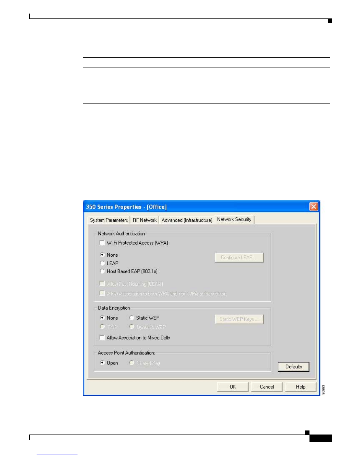
5-21
Cisco Aironet 340, 350, and CB20A Wireless LAN Client Adapters Installation and Configuration Guide for Windows
OL-1394-07
Chapter 5 Configuri ng the Client Adapter
Setting Network Security Parameters
Go to the next section to set additional parameters or click OK to return to the Profile Manager screen.
On the Profile Manager screen, click OK or Apply to save your changes.
Setting Network Security Parameters
The Network Security screen (see Figure 5-5) enables you to set parameters that control how the client
adapter associates to an access point, authenticates to the wireless network, and encrypts and decrypts
data. To access this screen, select the Network Security tab from the Properties screens.
Figure 5-5 Network Security Screen
Beacon Period (Kµs) Specifies the duration between beacon packets, which are used to help
clients find each other in ad hoc mode.
Range: 20 to 976 Kµs
Default: 100 Kµs
Table 5-5 Advanced (Ad Hoc) Parameters (continued)
Parameter Description
Page 92

5-22
Cisco Aironet 340, 350, and CB20A Wireless LAN Client Adapters Installation and Configuration Guide for Windows
OL-1394-07
Chapter 5 Configuring the Client Adapter
Setting Network Security Parameters
This screen is d ifferen t from the other Proper ties screens in that it p resents se ver al security f eatures, ea ch
of which involves a number of steps. In addition, the security features themselves are complex and need
to be understood before they are implemented. Therefore, this section provides an overview of the
security features as well as procedures for using them.
However , before you determine the appropriate security settings for your client adapter, you must decide
how to set the Allow Asso ciation to Mixed Cells parameter , which ap pears at the bottom of the Network
Security screen and is not associated to any of the security features. See the “Setting the Allow
Association to Mixed Cells Param eter” section below.
Setting the Allow Association to Mixed Cells Parameter
The Allow Association to Mixed Cells parameter indicates whether the client adapter can associate to
an access point that allows both WEP and non-WEP associations. Follow the steps below to set this
parameter.
Note This parameter is unavailable if the Wi-Fi Protected Acc ess (WPA) check box is checked.
Step 1 Perform one of the following:
• Check the Allow Association to Mixed Cells check box if the access point with which the client
adapter is to associate has WEP set to Optional and WEP is enabled on the client adapter. Otherwise,
the client is unable to establish a connection with the access point.
• Uncheck the Allow A ssoci atio n to Mixed C ells c he ck b ox if the a cce ss poin t wi th w hi ch th e cl ien t
adapter is to associate does not have WEP set to Optional. This is the default setting.
Note For security reasons, Cisco recommends that WEP-enabled and WEP-disabled clients not be
allowed in the same cell because broadcast packets are sent unencrypted, even to clients running
WEP.
Step 2 Perform one of the following:
• If you do not want to change any other paramete rs on the Network Se curit y screen, cl ick OK to
return to the Profile Manager screen; then click OK or Apply to save your changes
• If you want to change some of the othe r para me ters on the Networ k Secur ity scree n, g o to the next
section.
Overview of Security Featu res
You can protect your data as it is transmitted through your wireless network by encrypting it through the
use of wired equivalent privacy (WEP) encryption keys. With WEP encryption, the transmitting device
encrypts each packet with a WEP key, and the receiving device uses that same key to decrypt each
packet.
Page 93

5-23
Cisco Aironet 340, 350, and CB20A Wireless LAN Client Adapters Installation and Configuration Guide for Windows
OL-1394-07
Chapter 5 Configuri ng the Client Adapter
Setting Network Security Parameters
The WEP keys used to encrypt and decrypt transmitted data can be statically associated with your
adapter or dynamically created as part of the EAP authentica tion process. The informat ion in the “Static
WEP Keys” and “EAP (with Dynamic WEP Keys)” sections be low can help you to decide which type
of WEP keys you want to use. Dynamic WEP keys with EAP offer a higher degree of security than static
WEP keys.
WEP keys, whether static or dyna mic , are e ith er 40 o r 1 28 bits in len gth. 12 8-b it WE P keys offer a
greater level of security than 40-bit WEP keys.
Note Refer to the “Additional WEP Key Security Features” section on page 5-28 for information on three
security features that ca n make your WEP keys even more secure.
Static WEP Keys
Each device (or profile) w ith in yo ur wi reless ne twork can be assign ed u p to fo ur stat ic WE P keys. If a
device receives a packet that is not encrypted with the a ppropr iate key (as the WEP keys of all devices
that are to communicate with each other must match), the device discards the packet and never delivers
it to the intended receiver.
Static WEP keys are write-only and temporary; therefore, they cannot be read back from the client
adapter, and they are lost when power to the adapter is removed or the Windows device is rebooted.
Although the keys are temporary, you do not need to re-enter them each time the client adapter is inserted
or the Windows device is rebooted. Th is i s beca use th e keys are st ored (in an e ncry pt ed f orm at for
security reasons) in the registry of the Windows device. When the driver loads and reads the client
adapter’s registry parame ters, it also find s the s tat ic WE P keys, une ncryp ts t hem, a nd stor es them i n
volatile memory on the adapter.
The Network Security screen enab les you to view the curre nt WEP key settings for the cl ient adapter and
then to assign new WEP ke ys or ov erwr ite e xisting WEP ke ys as well as to enabl e or disab le static WEP.
Refer to the “Using Static WEP” section on page 5-32 for instructions.
EAP (with Dynamic WEP Keys)
The new standard for wireless LAN secu rity, as defined by the Institute of Electri cal and E lectronic s
Engineers (IEEE), is called 802.1X for 802.11, or simply 802.1X. An access point that supports 802.1X
and its protocol, Extensi ble Auth entica tion Protoc ol (EAP) , acts as th e interfac e betwee n a wireless
client and an authentication server, such as a Remote Authentication Dial-In User Service (RADIUS)
server, to which the access point communicates over the wired network.
Two 802.1X authenticat ion typ es c an be se le cted in ACU for use w it h Windows operating system s:
• EAP-Cisco Wireless (or LEAP)—This authentication type is av ailable for W indo ws 98, 98 SE, NT,
2000, Me, and XP, as well as non-Windows systems. Support f or LEA P is provi ded n ot in the
Windows operating system but in your client adapter’s firmware and the Cisco software that
supports it. RADIUS servers that support LEAP include Cisco Secure ACS version 2.6 and greater,
Cisco Access Registrar version 1.7 and greater, and Funk Software’s Steel-Belted RADIUS version
3.0 and greater.
LEAP is enabled or disab led for a specif ic profi le through A CU, pro vided the LEAP security module
was selected during inst al lati on. A fte r LEA P i s enabl ed, a variety of c onfigurat ion op tio ns are
available, including how and when a username and password are entered to begin the authentication
process.
Page 94

5-24
Cisco Aironet 340, 350, and CB20A Wireless LAN Client Adapters Installation and Configuration Guide for Windows
OL-1394-07
Chapter 5 Configuring the Client Adapter
Setting Network Security Parameters
The username and password are used by the client adapter to perform mutual authentication with the
RADIUS server through the access point. The username and password are stored in the client adapter’s
volatile memory; therefore, they are temporary and need to be re-entered whenever power is removed
from the adapter, typically due to the client adapter being ejected or the system powering down.
Note If the LEAP security module was not selected during installation, the LEAP option is
unavailable in ACU. If you want to be able to enable and disable LEAP, you must run the
installation program again and select LEAP.
• Host Based EAP—Selecting this option enables you to use any 802.1X authentication type for
which your operating system has support. For example, if your operating system uses the Microsoft
802.1X supplicant, it provides n ative support for EAP-TLS authe nticat ion and gener al suppor t for
PEAP and EAP-SIM authentication.
Note T o use EAP-TLS, PEAP, or EAP-SIM authentication, you must install the Microsoft 802.1X
supplicant, A CU, and the PEAP or EA P-SIM secur ity module; conf igur e your cli ent adapter
using ACU; enable the authentication type in Windows; and enable Network-EAP on the
access point.
–
EAP-TLS—EAP-TLS is enabled or disabled through the operating system and uses a dynamic
session-based WEP key, which is derived from the client adapter and RADIUS server, to encrypt
data. Once enabled, a few configuration parameters must be set within the operating system.
RADIUS servers that su pport EA P-TLS auth en ticati on incl ude Cisco Se cure ACS version 3.0
or greater and Cisc o Acc ess Regi strar version 1. 8 o r gre ater.
Note EAP-TLS requires the use of a certificate. Refer to Microsoft’s documentation for
information on downloading and installing the certificate.
–
Protected EAP (or PEAP)—PEAP authentication is designed to support One-Time Password
(OTP), Windo ws NT or 2000 domain, and LDAP user databases over a wireless LAN. It is based
on EAP-TLS authenticati on but uses a password or PIN instea d of a client certificate for
authentication. PEAP i s ena bl ed o r disab led t hrough t he ope rat ing syste m and u ses a dy nami c
session-based WEP key, which is derived from the client adapter and RADIUS server, to encrypt
data. If your network uses an OTP user database, PEAP requires you to enter either a hardware
token password or a software token PIN to start the EAP authentication process and gain access
to the network. If your network uses a Windows NT or 2000 domain user database or an LDAP
user database (such as NDS), PEAP requires you to enter your username, password, and domain
name in order to start the authentication process.
RADIUS servers that support PEA P aut henti cation inc lude Ci sco Secur e ACS version 3.1 or
greater and Cisco A cc ess Registra r versio n 3.5 or g reater.
Note Windows XP Service Pack 1 and the Microsoft 802.1X supplic ant for Windows 2000
include Microsoft’s PEAP supplicant, which supports a Windows username and
password only and does not interop er ate with Cisco’s PEAP supplicant. To use Cisco’s
PEAP supplicant, install the I nstall W iza rd file after Windows XP Service P ack 1 or the
Microsoft 802.1X suppl icant for Windows 2000. Otherwi se, Cisco ’s PEAP supplicant
is overwritten by Microsoft’s PEAP supplicant.
Page 95

5-25
Cisco Aironet 340, 350, and CB20A Wireless LAN Client Adapters Installation and Configuration Guide for Windows
OL-1394-07
Chapter 5 Configuri ng the Client Adapter
Setting Network Security Parameters
–
EAP-SIM—EAP-SIM authentication is designed for use in public wireless LANs and requires
clients equipped with PCSC-compliant smartcard readers. The EAP-SIM supplicant included in
the Install Wizard file supports only Gemplus SIM+ cards; however, an updated supplicant is
available that supports standard GSM-SIM cards as well as more recent versions of the
EAP-SIM protocol. T he new suppl icant i s available for downloa d f rom t he ftpe ng FTP se rver
at the following URL:
ftp://ftpeng.cisco.com/ftp/pwlan/eapsim/CiscoEapSim.dll
Please note that the abo v e req uire me nts are necess ary b ut not suf ficient to successfully perf orm
EAP-SIM authentication. Typically, you are also required to enter into a service contract with
a WLAN service provider, who must support EAP-SIM authentication in its network. Also,
while your PCSC smartcard reader may be able to read standard GSM-SIM cards or chips,
EAP-SIM authentication usu ally requir es your GSM ce ll phone ac count to be provisio ned for
WLAN service by your service provider.
EAP-SIM is enabled or disabled through the operating system and uses a dynamic session-based
WEP key, which is derived from the client adapter and RADIUS server, to encrypt data.
EAP-SIM requires y ou to e nte r a use r veri fication c ode, or PIN, for communication with the
SIM card. You can choose to have the PIN stored in you r compu ter or to be prom pted t o ent er
it after a reboot or prior to every authent icatio n attempt .
RADIUS servers that suppor t E AP-SIM includ e Cisc o Ac cess Registrar vers ion 3 .0 or g reate r.
Note Because EAP-TLS, PEAP, and EAP-SIM au thenticatio n are en abled in the operatin g system
and not in A CU, y ou cann ot switc h be twee n these a ut henti cat ion types simply by switching
profiles in ACU. You c an c rea te a pr ofile in ACU that uses host - bas ed E AP, but you must
enable the spe cific a uthe nti cat ion type in Windows (provided Windows uses the Mi crosof t
802.1X supplicant). In additio n, Windows can be set for only one aut henti cation type at a
time; therefore, if you have more than one profile in ACU that uses host-based EAP and you
want to use another authe ntic at ion ty pe, yo u must chan ge authe nti cat ion typ es in Windows
after switching profiles in ACU.
When you enable Network-EAP or EAP on you r acc ess point and co nfigure your clien t adapter for
LEAP, EAP-TLS, PEAP, or EAP-SIM, authentication to the network occurs in the following sequence:
1. The client associates to an access point and begins the authentication process.
Note The client does not gain full access to the network until authentication between the client
and the RA DI US se rver is su cc e ssfu l.
2. Communicating through the access point, the client and RADIUS server complete the authentication
process, with the password (LEAP and PEAP), certificate (EAP-TLS), or internal key stored on the
SIM card and in the servi ce provid er’s Authenticatio n Center (EAP- SIM) being the shared secr et for
authentication. The password or internal key is never transmitted during the process.
3. If authentication is succ essful , the clie nt an d RADI US serv er der i v e a dyn amic, sessio n-base d WEP
key that is unique to the client.
4. The RADIUS server transmits the key to the acc ess poin t u sing a sec ure c hannel on the wir ed LAN.
5. For the length o f a session, or time per iod, the access point and the client use this key to encrypt or
decrypt all unicast packet s (and broa dcast packet s if the acc ess point is set up to do so) that travel
between them.
Page 96

5-26
Cisco Aironet 340, 350, and CB20A Wireless LAN Client Adapters Installation and Configuration Guide for Windows
OL-1394-07
Chapter 5 Configuring the Client Adapter
Setting Network Security Parameters
Refer to the “Ena bling LE AP” section on page 5-35 for i nstru cti ons on ena bli ng LEA P or to t he
“Enabling Host-Based EAP” section on page 5-39 for instructions on enabling E A P-TLS, PEAP, or
EAP-SIM.
Note Refer to the IEEE 802.11 Standard for more information on 802.1X authentication and to the following
URL for additional i nforma tion on RADIUS ser vers:
http://www.cisco.com/univercd/cc/td/doc/product/software/ios120/12cgcr/secur_c/scprt2/scrad.htm
Wi-Fi Protected Access (WPA)
Wi-Fi Protected Access (WPA) is a standards-based, int erope r able s ecu rity e nhanc eme nt t hat gre atly
increases the level of data protection and access control for existing and future wireless LAN systems.
It is derived from and will be compatible with the upcoming IEEE 802.11i standard. WPA leverages
Temporal Key Integrity Protocol (TKIP) and Michael message integrity check (MIC) for data protection
and 802.1X for aut hent ic ate d key m anage men t.
WPA supports t wo mutually exclusive key management types: WPA and WPA-Pr e-shared key
(WPA-PSK). Using WPA key management, clients and the authentication server authenticate to each
other using an EAP authentication method, and the client and server generate a pairwise master key
(PMK). The server generates the PMK dynamically and passes it to the access point. Using WPA-PSK
key management, however, you configure a pre-shared key on both the client and the access point, and
that pre-shared key is used as the PMK.
Only 350 series and CB20A cards that ar e installed on c omputer s running Windows 2000 or XP and
running LEAP or h ost -base d EAP au then tic atio n c an b e used wit h WPA. Support for WPA is available
in the software c ompon en t s inc lude d in I nst all Wizard version 1. 2 or gr ea ter. However, if you want to
use host-based EAP authentication with WPA, you must install additional software with WPA support.
The following WPA software is recommended for use with Cisco Aironet client adapters:
• Funk Odyssey Client supplica nt version 2. 2 ( for Windows 2000)
• Windows XP Service Pack 1 and Microsoft support patch 815485 (for Windows XP)
Note Meetinghouse AEGIS Client supplicant version 2.1 is also supported for use with Windows 2000
and XP; however, it was not tested with this client adapter software release.
Refer to the “Enabling LEAP” section on pa ge 5-35 for instructions on enabling LEAP with WPA or to
the “Enabling Host-Based EAP” sect io n on page 5-39 for instructions on enabling EAP-TLS, PEAP, or
EAP-SIM with WPA.
Note WPA must also be en abled on the access point. Acc ess points must use Cisco IOS Release 12.2(11)JA
or greater to enable WPA. Refer to the documentation fo r yo ur a cce ss point f or in str uctio n s on en a bli ng
this feature.
Fast Roaming (CCKM)
Some applications that run on a client device may require fast roaming between access points. Voice
applications, for example, require seamless roaming to prevent delays and gaps in conversation. Support
for fast roaming is available for LEAP-enabled clients in Install Wizard version 1.1 or greater.
Page 97

5-27
Cisco Aironet 340, 350, and CB20A Wireless LAN Client Adapters Installation and Configuration Guide for Windows
OL-1394-07
Chapter 5 Configuri ng the Client Adapter
Setting Network Security Parameters
During normal operation, LEAP-enabled clients mutually authenticate with a new access point by
performing a comp let e LE AP auth en tic ation , i ncl udin g c omm unic atio n w ith the m a in RA DIU S ser ver.
However , when you configure your wireless LAN for fast roaming, LEAP-enabled clients securely roam
from one access point to another without the need to reauthenticate with the RADIUS server. Using
Cisco Centralized Key Management (CCKM), an access point that is configured for wireless domain
services (WDS) uses a fast rekeying technique that enables client devices to roam from one access point
to another in under 150 milliseconds (ms). Fast roaming ensures that there is no perceptible delay in
time-sensitive applications such as wireless Voice over IP (VoIP), enterprise resource planning (ERP),
or Citrix-based solutions.
This feature is enabled on the client adapter in two ways, depending on the software installed:
• If you are using ACU version 6.2 and client adapter firmware version 5.30.15 (which is included in
Install Wizard version 1.2), you need to enabl e fast roami ng in ACU. Refer to Step 10 in the
“Enabling LEAP” section for details.
• If you are using client adapter firmware version 5.20.17 (which is included in Install Wizard version
1.1), fast roaming is supported automatically.
Regardless of how fast roaming i s enabl ed on the cl ient ad ap ter, it must al so be e nabl ed o n th e ac cess
point.
Note Access points must use Cisco IOS Release 12.2(11)JA or greater to enable fast roaming. Refer to the
documentation for you r access point for instr uctions on en ablin g this fea ture.
Note If the Microsoft 802.1X supplicant is installed on your computer, you must disable one or two Windows
parameters in order for this f eature to operate co rrectly . Refer to St ep 13 in the “Enabling LEAP” section
for details.
Reporting Access Points that Fail LEAP Authentication
Client adapter firmware version 5.02.20 or greater and the following acc ess point firmware versions
support a feature that is designed to detect access points that fail LEAP authentication:
• 12.00T or great er ( 340, 3 50, a nd 12 00 se ries a cce ss p oint s)
• Cisco IOS Release 12.2(4)JA or greater (1100 series access points)
An access point running one of t hese firmware versio ns records a message in the system log whe n a
client running firmware version 5.02.2 0 or greater di scovers and reports an other acc ess point in th e
wireless network that has failed LEAP authentication.
The process takes place as follows:
1. A client with a LEAP profile attempts to associate to access point A.
2. Access point A does not ha ndle LE AP authentic ation suc cessfully, perhaps because the a ccess po int
does not understand LEAP or ca nnot com muni cate to a trust ed LEAP a uthent icati on server.
3. The client rec ords the M AC address for access point A and th e reason w hy the associa tion failed.
4. The client associates successfully to access point B.
5. The client sends the MAC address of access point A and the reason code for the failure to access
point B.
6. Access point B logs the failure in the system log.
Page 98

5-28
Cisco Aironet 340, 350, and CB20A Wireless LAN Client Adapters Installation and Configuration Guide for Windows
OL-1394-07
Chapter 5 Configuring the Client Adapter
Setting Network Security Parameters
Note This feature d oes no t ne ed to be en ab led on t he cl ient ad ap ter or ac cess p oin t; i t i s sup porte d
automatically in the firmware of both devices. However, both the client and access point must use these
firmware versions or greater.
Additional WEP Key Security Features
The three security features discussed in this section (MIC, TKIP, and broadcast key rotation) are
designed to prevent sophistic ated a ttac ks o n you r w ire le ss networ k’s WEP keys. These features do not
need to be enabled on the client adapter; they are supported automatically in the firmware and driver
versions included in the Install Wizard file. However, they must be enabled on the access point.
Note Access point firmware version 11.10T or greater is required to enable these security features. Refer to
the documentation for your access point for instructions on enabling these security features.
Message Integrity Check (MIC)
MIC prevents bit-flip attacks on encrypted packets. During a bit-flip attack, an intruder intercepts an
encrypted message, alters it slightly, and retransmits it, and the receiver accepts the retransmitted
message as legitimate. The MIC adds a few bytes to each packet to make the packets tamper-proof.
The Status scre en ind icat es if MI C is be ing use d, and th e St atist ics sc reen provides MIC sta tis tics .
Note If you enable M IC o n the acc ess poi n t, y our cl ient ad ap ter ’s driver must support these features;
otherwise, the client cannot associate.
Temporal Key Integrity Pr otocol (TKIP)
This feature, also referred to as WEP key hashing, defends against an attack on WEP in which the
intruder uses the init ialization vect or (IV) in en crypted p acket s to calculate the WEP ke y. TKIP removes
the predictability that an intrud er relies o n to de termi ne th e WEP key by exp loitin g IVs. It pro tec ts both
unicast and broadcast WEP keys.
Note If you enable TKIP on the access point, your client adapter’s firmware must support these features;
otherwise, the client cannot associate.
Note TKIP is automatically enabled whenever WPA is enabled, and it is disabled whenever WPA is disabled.
Broadcast Key Rotation
EAP authentication provides dynamic unicast WEP keys for client devices but uses static broadcast, or
multicast, keys. When you enable broadcast WEP key rotation, the access point provides a dynamic
broadcast WEP key and changes it at the interval you select. When you enable this feature, only wireless
client devices using LEAP, EAP-TLS, PEAP, or EAP-SIM authentication can associate to the access
point. Client devices u si ng st ati c WE P ( with op en or sh ar ed key aut hent ica tion) c annot assoc ia te.
Page 99

5-29
Cisco Aironet 340, 350, and CB20A Wireless LAN Client Adapters Installation and Configuration Guide for Windows
OL-1394-07
Chapter 5 Configuri ng the Client Adapter
Setting Network Security Parameters
Synchronizing Security Features
In order to us e any o f th e secur i ty f eat ures di scu ssed i n thi s s ect ion, bo th y our c lient adap te r a nd the
access point to which it will associate must be set appro priately . Table 5-6 indicates the client and access
point settings required for ea ch securi ty feature . This chap ter pro vides spe cif ic instr uctions fo r enabling
the security features on your client adapter. Refer to the documentation for your access point for
instructions on enabling any of these features on the access point.
Table 5-6 Client and Access Point Security Settings
Security Feature Client Setting Access Point Setting
Static WEP with open
authentication
Disable Network Authentication,
enable Static WEP and Open
Authentication and create a WEP
key
Set up and enable WEP and enable
Open Authentication for the SSID
Static WEP with shared key
authentication
Disable Network Authentication,
enable Static WEP a nd Shar ed K e y
Authentication and create a WEP
key
Set up and enable WEP and enable
Shared Key Authentication for the
SSID
LEAP authentication Enable LEAP Set up and enable WEP and enable
Network-EAP for the SSID
LEAP authentication with
WPA
Enable LEAP and Wi-Fi Prote cte d
Access (WPA)
Note To allow the client to
associate to bo th WPA and
non-WPA access points,
enable Allow Association
to both WP A and non-WP A
authentica to rs .
Select a cip her su ite th at in clu des
TKIP, set up and enable WEP, and
enable Network-EAP and WPA for
the SSID
Note To allow both WPA and
non-WP A clients to use the
SSID, enable optional
WPA.
EAP-TLS authentication
If using ACU to
configure card
Enable Host Based E A P (8 02.1x)
and Dynamic WEP in ACU and
select Enable network access
control using IEEE 802.1X (or
Enable IEEE 802.1x au thentication
for this network) and Certificates
(or Smart Ca rd or other Ce rtifi cate)
as the EAP Type in Windows
Set up and enable WEP and enable
Open Authentication for the SSID
and specify the u se of E AP
If using Windows XP
to configure card
Select Enable network access
control using IEEE 802.1X and
Smart Card or other Certificate as
the EAP Type
Set up and enable WEP and enable
Open Authentication for the SSID
and specify the u se of E AP
Page 100

5-30
Cisco Aironet 340, 350, and CB20A Wireless LAN Client Adapters Installation and Configuration Guide for Windows
OL-1394-07
Chapter 5 Configuring the Client Adapter
Setting Network Security Parameters
EAP-TLS authentication with WPA
If using ACU to
configure card
Enable Wi-Fi Protected Access
(WPA), Host Based EAP (WPA),
and Dynamic WEP in ACU and
enable WPA and select Enable
network access control using IEEE
802.1X and Certificate s (o r Smart
Card or Other Certificate) as the
EAP Type in Windows
Select a cip her su ite th at in clu des
TKIP; set up and enable WEP; and
enable WPA and Open
Authentication for the SSID and
specify the use of EAP
Note To allow both WPA and
non-WP A clients to use the
SSID, enable optional
WPA.
If using Windows XP
to configure card
Enable WPA and select Enable
network access control using IEEE
802.1X and Smart Card or o ther
Certificate as the EAP Ty pe
Select a cip her su ite th at in clu des
TKIP; set up and enable WEP; and
enable WPA and Open
Authentication for the SSID and
specify the use of EAP
Note To allow both WPA and
non-WP A clients to use the
SSID, enable optional
WPA.
PEAP authentication
If using ACU to
configure card
Enable Host Based E A P (8 02.1x)
and Dynamic WEP in ACU and
select Enable network access
control using IEEE 802.1X (or
Enable IEEE 802.1x au thentication
for this network) and PEAP as the
EAP Type in Windows
Set up and enable WEP and enable
Open Authentication for the SSID
and specify the u se of E AP
If using Windows XP
to configure card
Select Enable network access
control using IEEE 802.1X and
PEAP as the E AP Type
Set up and enable WEP and enable
Open Authentication for the SSID
and specify the u se of E AP
PEAP authentication with WPA
If using ACU to
configure card
Enable Wi-Fi Protected Access
(WPA), Host Based EAP (WPA),
and Dynamic WEP in ACU and
enable WPA and select Enable
network access control using IEEE
802.1X and PEAP as the EAP T ype
in Windows
Select a cip her su ite th at in clu des
TKIP; set up and enable WEP; and
enable WPA and Open
Authentication for the SSID and
specify the use of EAP
Note To allow both WPA and
non-WP A clients to use the
SSID, enable optional
WPA.
Table 5-6 Client and Access Point Security Settings (continued)
Security Feature Client Setting Access Point Setting
 Loading...