

Page 1

Corporate Headquarters
Cisco Systems, Inc.
170 West Tasman Drive
San Jose, CA 95134-1706
USA
http://www.cisco.com
Tel: 408 526-4000
800 553-NETS (6387)
Fax: 408 526-4100
Cisco Aironet Wireless LAN Client
Adapters Installation and Configuration
Guide for MS-DOS
Text Part Number: OL-1744-02
Page 2

THE SPECIF ICA TIONS AND IN FOR M AT IO N RE GA RDING THE PR ODU C TS IN T HI S MAN UA L A RE S U B JEC T TO CH AN GE WITH O UT
NOTICE. ALL STATEMENTS, INFORMATION, AND RECOMMENDATIONS IN THIS MANUAL ARE BELIEVED TO BE ACCURATE BUT ARE
PRESENTED WITHOUT WARRANTY OF ANY KIND, EXPRESS OR IMPLIED. USERS MUST TAKE FULL RESPONSIBILITY FOR THEIR
APPLICATION OF ANY PRODUCTS.
THE SOFTWARE LICENSE AND LIMITED WARRANTY FOR THE ACCOMPANYING PRODUCT ARE SET FORTH IN THE INFORMATION
PA CKET THA T SHIPPED WITH THE PRODUCT AND ARE INCORPORATED HEREIN BY THIS REFERENCE. IF YOU ARE UNABLE TO LOCATE
THE SOFTWARE LICENSE OR LIMITED WARRANTY, CONTACT YOUR CISCO REPRESENTATIVE FOR A COPY.
The Cisco implementation of TCP header compression is an adaptation of a program developed by the University of California, Berkeley (UCB) as part of
UCB’s public domain version of the UNIX operating system. All rig hts reser ved. Copyright © 1981, Regents of the University of C a lifor ni a.
NOT W ITHSTANDING ANY OTHER WA RRANTY HEREIN, ALL DOCUMENT FILES AND SOF TWARE O F THESE SUPPLIERS AR E PROVIDED
“AS IS” WITH ALL FAULTS . CIS CO AN D TH E A BOVE-NAMED S UP PLIERS DISCLA IM AL L WARRANTIES, EX P RES S ED OR IMPLIED,
INCLUDING, WITHOUT LIMITATION, THOSE OF MERCHANTABILITY, FITNESS FOR A PARTICULAR PURPOSE AND NONINFRINGEMENT
OR ARIS I N G F ROM A C O U R SE OF DEALING, U SAGE, OR TRADE P RACTICE.
IN NO EVENT SHALL CISCO OR I TS SUPPLIERS BE LIABLE FOR ANY INDIRECT, SPECIAL, CONSEQUENTIAL, OR INCIDENTAL
DAMAGES, INCLUDING, WITHOUT LIMITATION, LOST PROFITS OR LOSS OR DAMAGE TO DATA ARISING OUT OF THE USE OR
INABILITY TO USE THIS MANUAL, EVEN IF CISCO OR I TS SUPPLIERS HAVE BEEN ADVISED OF THE POSSIBILITY OF SUCH DAMAGES.
Cisco Aironet Wireless LAN Client Adapters Installation and Configuration Guide for MS- DOS
Copyright © 2002, Cisco Systems , Inc .
All rights reserved.
CCIP, the Cisco Powered Network mark, the Cisco Systems Verified logo, Cisco Unity, Follow Me Browsing, FormShare, Internet Quotient, iQ Breakthrough, iQ Expertise, iQ
F
astTrack, the iQ Logo, iQ Net Readiness Scorecard, Networking Academy, ScriptShare, SMARTnet, TransPath, and Voice LAN are trademarks of Cisco Systems, Inc.; Changing
t
he Way We Work, Live, Play, and Learn, Discover All That’s Possible, The Fastest Way to Increase Your Internet Quotient, and iQuick Study are service marks of Cisco Systems,
I
nc.; and Aironet, ASIST, BPX, Catalyst, CCDA, CCDP, CCIE, CCNA, CCNP, Cisco, the Cisco Certified Internetwork Expert logo, Cisco IOS, the Cisco IOS logo, Cisco Press,
Cisco Systems, Cisco Systems Capital, the Cisco Systems logo, Empowering the Internet Generation, Enterprise/Solver, EtherChannel, EtherSwitch, Fast Step, GigaStack, IOS,
I
P/TV, LightStream, MGX, MICA, the Networkers logo, Network Registrar, Packet, PIX, Post-Routing, Pre-Routing, RateMUX, Registrar, SlideCast, StrataView Plus, Stratm,
SwitchProbe, TeleRouter, and VCO are registered trademarks of Cisco Systems, Inc. and/or its affiliates in the U.S. and certain other countries.
A
ll other trademarks mentioned in this document or Web site are the property of their respective owners. The use of the word partner does not imply a partnership relationship
b
etween Cisco and any other company. (0203R)
Page 3

i
Cisco Aironet Wireless LAN Client Adapters Installtion and Conf iguration Guide for MS-DOS
OL-1744-02
CONTENTS
Preface v
Audience vi
Purpose vi
Organization vi
Conventions vi
Related Publications vii
Obtaining Documentation vii
World Wide Web vii
Document ation C D-R OM vii
Ordering Documentation viii
Document ation Fe edb ack viii
Obtaining Technical Assistance viii
Cisco.com viii
Technical Assistance Center ix
Contacting TAC by Using the Cisco TAC Website ix
Contacting TAC by Telephone ix
CHAPTER
1 Overview 1-1
Introduction to the Wireless LAN Adapters 1-2
Terminology 1-3
Parts of the Client Adapter 1-3
Radio 1-3
Radio Antenna 1-4
LEDs 1-4
Radio Ranges 1-4
Link Test 1-5
Data Transparency and Protocols 1-5
Protocols Supported 1-5
Security Features 1-6
System Configurations 1-6
Ad Hoc Wireless LAN 1-6
Wireless Infrastructure 1-7
Wireless Infrastructure with Workstations Accessing a Wired LAN 1-7
Extended Infrastructure Using Repeaters 1-8
Page 4

Contents
ii
Cisco Aironet Wireless LAN Client Adapters Installtion and Conf iguration Guide for MS-DOS
OL-1744-02
Coverage Options 1-9
Minimal Overlap Coverage 1-9
Heavy Overlap Coverag e 1-9
Multiple Overlapping Systems Coverage 1-10
CHAPTER
2 Installing the Hardware 2-1
Safety Information 2-2
FCC Safety Compliance Statement 2-2
Safety Guidelines 2-2
Warnings 2-2
Other Devices in the Wireless Network 2-3
Unpacking the Client Adapter 2-3
Package Contents 2-3
Antenna Connectors 2-4
Attaching a Remote Antenna 2-4
Detaching a Remote Antenna 2-5
Inserting the Client Adapter into a Computing Device 2-5
Inserting a PC Card 2-5
Inserting a PCI Client Adapter 2-6
Removing the Client Adapter 2-7
Removing a PC Card 2-7
Removing a PCI Client Adapter 2-7
CHAPTER
3 Installing the Software 3-1
Driver Overview 3-2
Windows for Workgroups 3.11 NDIS2 Installation 3-3
DOS NDIS2 Installation 3-3
DOS Packet Driver Installation 3-4
ODI Driver Installation 3-5
Additional Requirements and Features 3-5
Driver Keywords and Settings 3-6
Basic System Parameters 3-7
Network Performance Variables 3-8
Fragmentation Variables 3-9
Power Management Variables 3-10
Scanning Variables 3-12
Infrastructure Parameters 3-13
Ad Hoc Variables 3-16
Page 5

Contents
iii
Cisco Aironet Wireless LAN Client Adapters Installtion and Con fi guration Guide for MS-DOS
OL-1744-02
Adapter Keywords 3-16
CHAPTER
4 Utilities 4-1
Site Survey and Link Test 4-2
Using Windows 3.11 or DOS to Perform a Link Test Using Telnet 4-2
Loading New Firm wa re Vers ions 4-3
DOS Utilities 4-3
Configurat ion Utilit ies 4-3
Diagnostic Utilities 4-4
DOS Utilities Running Environment 4-4
Layout and Format 4-4
General Usage Notes 4-5
Syntax 4-5
Running the Utilit ies 4-5
Getting Help 4-5
Configurat ion Utilit ies 4-6
AWCLEAP.EXE 4-6
AWCALLID.EXE 4-7
AWCALLID.EXE 4-8
WEPDOS.EXE 4-9
Diagnostic Utilities 4-10
PCMCIA.COM 4-10
RADINFO.EXE 4-11
CHAPTER
5 Error Messages and Trouble Shooting 5-1
Accessing the Latest Troubleshooting Information 5-2
Interpreting the Indicator LEDs 5-2
If Your Radio Fails to Establish Contact 5-3
APPENDIX
A Technical Specifications A-1
Technical Spec ific ation s A-2
APPENDIX
B Channels, Power Levels, Antenna Gains B-1
Channel Sets B-2
Maximum Power Levels and Antenna Gains B-3
Page 6

Contents
iv
Cisco Aironet Wireless LAN Client Adapters Installtion and Conf iguration Guide for MS-DOS
OL-1744-02
APPENDIX
C Declarations of Conformity and Regulatory Information C-1
Manufacturers Federal Communication Commission Declaration of Conformity Statement C-2
Department of Communications – Canada C-3
Canadian Compliance Statement C-3
European Community, Switzerland, Norway, Iceland, and Liechtenstein C-4
Declaration of Conformity with Regard to the R&TTE Directive 1999/5/EC C-4
Declaration of Conformity for RF Exposure C-6
Guidelines for Operating Cisco Aironet Wireless LAN Client Adapters in Japan C-7
Japanese Translation C-7
English Translation C-7
APPENDIX
D Translated Safety Warnings D-1
Explosive Device Proximity Warning D-2
Lightning Activity Warning D-3
Installation Warning D-3
Circuit Breaker (15A) Warning D-4
I
NDEX
Page 7

v
Cisco Aironet Wireless LAN Client Ada pters Installation and Config ura ti on Gui de for MS- DO S
OL-1744-02
Preface
This prefa ce pr ovid es a n overvi ew o f th e Cisco Aironet Wireless LAN Client Adapters Installation and
Configuration Guide for MS-DOS, references related publications, and explains how to obtain other
document ati on a nd t ech n ica l assistan ce, if n ecessary.
These to pics a re cove re d in th is sect ion:
• Audience, page vi
• Purpose, page vi
• Organiz at ion, pa ge vi
• Conventio ns, pa ge v i
• Related Publications, page vii
• Obtaining Documentation, page vii
• Obtaini ng Technical A ssistance, p ag e v ii i
Page 8

vi
Cisco Aironet Wireless LAN Client Adapters Installation and Configuration Guide for MS-DOS
OL-1744-02
Preface
Audience
Audience
This publication is for the person responsible for installing, maintaining, and configuring a Cisco
Aironet Wireless LAN Adapter (a l so refe rr ed to as an adapter or clie nt adapt er) on a comput er usi ng t he
MS-DOS opera ting sy stem . The inst all er s hou ld be f ami li ar wit h MS-DOS, c omput ing devices and with
networ k terms an d conc e p ts .
Purpose
This publ ic ation desc ri be s th e adapters , ex pl ai ns how to i nst al l t he ad ap ter s a nd t he ass o ci ate d dr ivers
and software, and offers troubleshooting information.
Organization
Please read Chapters 2 and 3 before attempting to install or use the hardware and software described in
this guid e.
This guide is arranged as follows:
Chapter 1, “Overview,” pro vide s you wi th a gen eral i ntrod uction t o the wi reles s LAN ada pter s, des cribes
direct sequence radio technology, and the various adapter configurations you can use when operating the
adapter in you r infrast ruc ture .
Chapter 2, “Installing the Hardware,”describes the physical installation of the adapter and the standard
antenna.
Chapter 3, “Installing the Software,” describes the i nstallat ion and configu r ation of the various network
drivers.
Chapter 4, “Uti li ties,” provides detailed proce dures for using the utilities to perform link tests, site
surveys, configuration, diagnostics, as well as loading new firmware versions.
Chapter 5, “Err or Me ssa ges and Trouble Shoot in g,” pro v ides det ail ed des cri pti ons of th e LE D mess age s
and error co d es, as well a s g en er al pr o ced u re s f or co r r ect in g co mm o n pro bl em s.
Append ix A, “Technical S pe cifi cat io ns,” provides radio and physical specifications.
Appendix B, “ Cha nnels , P o we r Le v el s, Ante nna Ga in s, ” provides channel identifiers and channel center
frequenci es f or var iou s area regulatory ag en ci es .
Appendix C, “Declarations of Conformity and Regulatory Information,” provides conformity
informat io n ab ou t th e adapter.
Conventions
This publ ication u ses t h e f ollow in g co nvention s t o c onvey inst ru ct io ns and in for m at io n:
• Commands and keywords are boldface.
• Variables are in italics.
• Notes, cautions, an d w ar n in gs us e th e f o ll owi ng co nvent io ns an d sy m b o ls:
Page 9

vii
Cisco Aironet Wireless LAN Client Adapt er s Inst all ation and Configuration Guide fo r MS-DOS
OL-1744-02
Preface
Related Public ati ons
Note Means reader take note. Notes contain helpful suggestions or references to materials not contained
in this m an u al.
Caution Means reader be careful. In this situ ation, yo u migh t do s o m et hi ng that c ou ld r es u lt in equi pm ent
damag e or los s of data .
Related Publicat ions
For more information about Cisco Aironet Wireless LAN Adapters and related products, refer to these
publicat ions:
• Quick St a r t G u id e f or Cisco Aironet Wireless L A N Cl ient Ad ap t e rs
• Releas e N o tes fo r C is co Aironet Wireless L AN Clie nt Adapter s
• Quick St a rt G u id e: Cisco A irone t Access Points
• Cisco Aironet Acces s Point Hardware Inst a lla ti o n G u id e
• Cisco Aironet Access Point Software Configuration Guide
• Cisco A i rone t Wireless L AN Client Adapters Inst al la ti on and C onfigura tio n G ui de for Linux
• User’s Guide and Technical Reference Manual Ai ronet Wireless LAN Adapt er PC4500 and PC4800
Obtaining D ocumentation
The following sections provide sources for obtaining documentation from Cisco Systems.
World Wide Web
You can access th e most cur re nt C is co d o cu men tation o n t h e World Wide Web at the f o ll owin g sit es :
• http:/ /w w w.cisco.com
• http://www-china.cisco.com
• http://www-europe.cisco.com
Documen t at i on CD-ROM
Cisco d oc umentation and addition al literat ur e are availabl e i n a CD- ROM pa c ka ge, which s h ip s
with your product. The Documentation CD-ROM is updated monthly and migh t be mor e curren t than
printed documentation. The CD-ROM package is available as a single unit or as an annual subscription.
Page 10

viii
Cisco Aironet Wireless LAN Client Adapters Installation and Configuration Guide for MS-DOS
OL-1744-02
Preface
Obtaining Technical Assistance
Orderi ng D ocum entation
Cisco documentation is available in the following ways:
• Registered Cisco Direct Customers can order Cisco Product documentation from the Networking
Products M a rk etP l ace :
http:/ /w w w.cisco.com/cg i- bin/or de r/order_r oot.pl
• Regis tere d Cis co. com use rs c an o rde r the Doc ument at ion CD-ROM through t he on li ne S ubs cri pti on
Store:
http://www.cisco.com/go/subscription
• Nonregist er ed C isco.com us er s can orde r do cu m e nt ati on t hr o ugh a local ac co unt r epresent ative by
calling Cisco corporate headquarters (California, USA) at 408-526-7208 or, in North America, by
calling 800-553-NETS(6387).
Documentation Feedback
If you are reading Cisco product documentation on the World Wide Web, you can submit technical
comments electronically. Click Feedback in the toolba r and s ele ct Doc umentation. After you complete
the form, clic k Submit to sen d it to Cisco .
Yo u ca n e-mail your c o m ments to bug-d oc@ci s co .c o m .
To submit your comments by mail, use the response card behind the front cover of your document, or
write to th e fo ll owi ng a dd r es s:
Attn Document Resource Connection
Cisco Systems, Inc.
170 West Tasman Drive
San Jose, CA 95134-9883
We appreciate your comments.
Obtaining Technical Assist ance
Cisco p rovi des Cisco.com a s a star t in g po in t fo r al l t ech n ica l assistan ce. Customers and p ar t ne rs can
obtain doc ument ation, trouble shooti ng tip s, and samp le conf igura tio ns from onli ne tools . For Cisco.c om
registered users, additional troubleshooting tools are available from the TAC website.
Cisco.com
Cisco.com is the foundation of a suite of interactive, networked services that provides immediate, open
access to Cisco information and resources at anytime, from anywhere in the world. This highly
integra ted Internet application is a powerful, easy-to-use tool for doing business with Cisco.
Cisco.com provides a broad range of features and services to help customers and partners streamline
busin ess pr oce sses and i mpro v e pr odu ct i vi ty. Through Ci sco .com, you can find informatio n a bou t Cis co
and our netw ork ing s olut ion s, servi c es, an d prog rams . In addi tio n, you can resolv e technic al is su es with
online t ech ni ca l s u p por t, d ow nl oa d an d t est s o ft ware packages, and orde r Ci s co le ar ni ng materials and
merchan d ise. Valuable onli ne skill as sessment, traini n g, an d cer ti fica tio n p rog ra m s are also avail ab le.
Page 11

ix
Cisco Aironet Wireless LAN Client Adapt er s Inst all ation and Configuration Guide fo r MS-DOS
OL-1744-02
Preface
Obtaining Technical Assistance
Customer s and pa rtners can self -regis ter on C isco.c om to obta in addi tional person alized i nformat ion and
services. Registered users can order products, check on the status of an order, access technical support,
and view be nefit s spe cific to thei r re lati on shi ps with Cisc o.
To access C isco.com, g o to th e following w e bsi te:
http:/ /w w w.cisco.com
Technical A ssi stance Center
The Cisco TAC website is available to all customers who need technical assistance with a Cisco product
or technology that is under warranty or covered by a maintenance contract.
Contact i ng TAC by Using the Cisco TAC Website
If you have a priority level 3 (P3) or priority level 4 (P4) problem, contact TAC by going to the TAC
website:
http:/ /w w w.cisco.com/tac
P3 and P4 level problems are defined as follows:
• P3—Your netw ork perf orm anc e i s d e gr aded . Ne tw or k fun ct iona li ty i s not i ceably i mpa ir ed, b ut mos t
busine ss operations continue.
• P4—You need in forma tion or ass is tanc e on C isc o p rod uct c apa bi liti es , prod uc t ins t all ati on, or bas ic
product configuration.
In each o f th e a bov e ca ses , use the Ci s co TAC website to q ui ck ly fin d an sw er s to y o ur q ue stions.
To register for Cisco.com, go to the following website:
http:/ /w w w.cisco.com/r egis t e r /
If you cann ot res olv e your te chni cal i ssue b y us ing t he TAC o nlin e re sour ce s, Ci sc o. com registered user s
can op en a cas e online by u s in g the TAC Cas e O pen tool at t he follow in g webs ite:
http:/ /w w w.cisco.com/tac/caseo pen
Contact ing TAC by Telephone
If you have a priority level 1(P1) or priority level 2 (P2) problem, contact TAC by telephone and
immediate ly open a case . To obtain a direc tory of t oll- fre e num bers fo r yo ur cou nt ry, go to the fol lo wi ng
website:
http:/ /w w w.cisco .com/wa rp /public/687/D irect or y /D irTAC.shtml
P1 and P2 level problems are defined as follows:
• P1—Your production network is down, causing a critical impact to business operations if service is
not re s to r e d qu ickly. No w or k a r ou n d is availa bl e .
• P2—Your production network is severely degraded, affecting significant aspects of your business
operations. No worka round is available.
Page 12

x
Cisco Aironet Wireless LAN Client Adapters Installation and Configuration Guide for MS-DOS
OL-1744-02
Preface
Obtaining Technical Assistance
Page 13

CHAPTER
1-1
Cisco Aironet Wireless LAN Adapte rs In stal lation and Configuration Guide for MS- DO S
OL-1744-02
1
Overview
This chapter describes the Cisco Aironet Wireless LAN Client Adapter, also referred to as an adapter or
client adapter, and il lu str a te s it s role in a w i reless network .
These to pics a re cove re d in th is sect ion:
• Introd uc tio n to the Wire less LAN A dapters, page 1- 2
• Parts of the Client Adapter, page 1-3
• Radio Ranges, page 1-4
• Data Transparency and Protocols, page 1-5
• System Configurations, page 1-6
• Covera ge Options, page 1-9
Page 14
1-2
Cisco Aironet Wireless LAN Adapters Instal lation and Configuration Guide for MS- DO S
OL-1744-02
Chapter1 Overview
Introduction to the Wireless LAN Adapters
Introducti on to the Wireless LAN Adapte rs
The Cisco Aironet Wire less LAN Client Adapters, also referred to as adapters, are radio modules that
provi de transp aren t, wirel ess, data communic ations be tween f ixe d, porta ble, or mobi le de vices and other
wireless d evice s o r a w i re d n et wo rk in fr ast r uc tu re . Th e ad ap ter s are fully co mp atible wh en u sed i n
devices supporting Plug-and-Play (PnP) technology. Host devices can be any device equipped with a PC
Card Type II or Type III slot. These devices include:
• Desktop systems
• Portable laptops
• Notebook computers
• Personal digital assistants
• Pen based computers
• Other d ata co ll ect ion devices
The prim a ry f u nc tio n of the ad ap t er s is to tr an s f er d ata p ackets transparent ly th r ou g h th e w ir eless
infrastr ucture. The adap ter s o p er at e s i m il ar ly to a standa rd networ k p ro d uc t ex cep t that th e cable is
replaced with a radio connection. No special wireless networking functions are required, and all existing
applications that operate over a network can operate using the adapters.
The PC Card can also be built into peripheral devices such as printers to provide them with a transparent
wireless connection to a wired network.
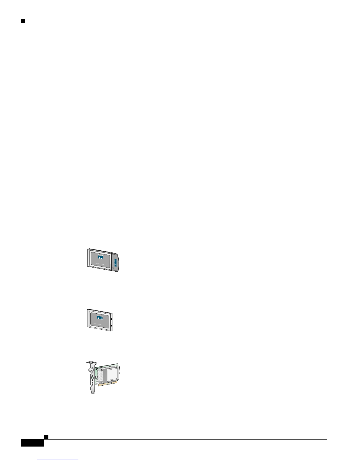
This document covers three types of adapters:
• PC card client adap ter (als o referred to as a PC card)—A PC M CI A c ar d ra di o mod u le th at can b e
inserted into any device equipped with an external Type II or Type III PC c ard s lot . Hos t devices can
include laptop s , notebook computers, personal digit al assistants, and hand-held or portable devices.
• LM card c lient adapter (also referred to a s an LM card)—A PCMCIA card radio modul e tha t can be
inserted into any device equipped with an internal Type II or Type III PC card slot. Host devices
usually include hand-held or portable devices.
• PCI clien t adapt er—A clie nt adap ter car d radio m odule t hat can be insert ed into any devic e equi pped
with an empty PCI expansion slot, such as a desktop computer.
Refe r to the “Radio Antenna” section on page 1-4 for antenna d iffer en ces betwee n t h ese adapters .
CISCO
A
IRO
NET 340
S
E
R
I
E
S
11 Mbps WIRELESS LAN ADAPTER
47519
C
ISCO
AIR
O
NET 340
S
E
R
I
E
S
11 Mbps WIRELESS LAN ADAPTER
47893
65189
Page 15

1-3
Cisco Aironet Wireless LAN Adapter s Inst all ation and Configuration Guide fo r MS-DO S
OL-1744-02
Chapter 1 Overview
Parts of th e Clien t Adap ter
Terminology
Througho ut th is do cu ment, the se t er m s ar e used:
• client adap ter—R efers to all three ty pes of adap ters
• PC card, LM c ar d, o r PCI cl ient adap te r— Refers on ly t o a sp ecific adap ter
• workstation (or station)—Refers to a co m p ut in g device w ith an instal led c li ent ad ap t er
• End Node—A client node that is loca ted at the end of the Network Tree.
• Infrastru ctu r e— The w ir el ess i nfr as t ruct ur e is t he co mm u n ica ti on s sy s te m that comb in es access
points, mobile nodes, and fixed nodes. Access points within the infrastructure can be either root
units, wh ich are p hys ic all y wi r ed to th e LA N ba ck bo n e, or can act as w i re les s re pe aters. Oth er R F
enabled devices serve as fixed nodes or mobile client nodes.
• Parent/Child Node—Refers to the relationships between nodes in the wireless infrastructure. The
complete set of relationships is sometimes described as a network tree. For example, the access point
(at the top of the t ree) would be the parent of the end nodes. Conversely, the end nodes would be the
children o f th e access p oi nt .
• Power Saving Protocol (PSP) a nd Non-Power Saving Protocol—The Power Saving Pr ot oc ol allows
computer s ( usu al ly p or t ab le c omputers) t o power u p on ly p art of the time to co ns er ve en ergy. If a
client node is using the Power Saving Protocol to communic ate with the network, the access point
must be aware o f th is mo de and imp le m en t ad di tio n al fe at ur es such as message st or e and f o rwar d .
If the clie nt node is powered from an AC line, do not use PSP.
• Repeater—A repeater is an access point that extends the radio range of the infrastructure. A repeater
is not physically attached to the wired LAN, but communicates through radio to another access
point, which is either a root unit or another repeater.
• Root Unit—The root unit is an a ccess point that is located at the top, or starting point, of a wireless
infrastructure. A root unit provides the physical connection to the wired LAN and contains
configuration information in its association table that covers all nodes that access the wired network
(backbone ). A ll ac ces s p o in ts di re ctl y att ach ed t o th e w i re d LA N b ack bo n e a re r oot un it s .
Parts of the Client Adapt er
The clie nt ad ap ter is composed o f th r ee major p arts : a r ad io, a radio an tenna, an d tw o LED s.
Radio
The client adapter conta ins a direct-sequen ce spread spectrum (DSSS) radi o that operates in the 2.4-GHz
license-free Indus trial Scientific Medical (ISM) band. The radio t ransmits data over a half-duplex radio
channel operating at up to 11 Mbps.
DSSS technology causes radio signals to be transmitted over a wide frequency range, using multiple
frequencies simultaneously. The benefit of this te chnology is its ability to protect the data transmission
from inte rf eren ce. Fo r ex amp le , if a part i cula r f reque nc y e ncoun te rs no ise , in te rf eren ce, or b oth, enoug h
redundancy is built into the signal on other frequencies that the client adapter usually is successful in its
transmission.
Page 16

1-4
Cisco Aironet Wireless LAN Adapters Instal lation and Configuration Guide for MS- DO S
OL-1744-02
Chapter1 Overview
Radio Ranges
Radio Antenna
The type of antenna used depends on your client adapter:
• PC cards have an integrated, permanently attached diversity antenna. The benefit of the dive rsity
antenna system is improved coverage. The system works by allowing the card to switch and sample
betwee n its tw o antenna ports in order t o se le ct the opti m um port fo r r ece ivin g data pac ket s. A s a
result, th e c a rd ha s a bet te r ch an ce o f maintaini n g t he r ad io fre qu en cy (R F) co n ne ction in areas o f
interferen ce. The an ten n a is loca ted w i th in th e s ect io n of t he card t hat p r otru d es f r om the PC c ar d
slot when the card is installed.
• LM cards are shipped without an antenna; however, an antenna can be connected through the card’s
extern al c onn ecto r. If a snap-on ante nna is us ed, it sh ould b e op erat ed in di v ers ity mode . Othe rwi se,
the anten na mode u s ed sh ou ld corresp on d to t he an te nn a p o rt t o w h ic h th e antenna is co nn ect ed .
• PCI clie nt ad ap te rs are ship p ed w it h a 2 - dB i d i po le an tenna tha t a tt ach es t o th e a da pt er ’s anten n a
connector. However , other types of antennas can be used. PCI adapters can be operated only through
the antenna port loc ated on the right side of the radio module (not to be confused with the antenna
connecto r on t he card car rier ).
Note External antennas used in combination with a power setting resulting in a radiated power level above
100 mW equivalent isotropic radiated power (EIRP) are not allowed for use within the European
community and other countries that have adopted the European R&TTE directive. CEPT
recommendation Rec 70.03, or both. For more details on legal combinations of power levels and
antennas i n th os e co u nt rie s, co nt act C is co C o rpo ra te Compli an ce.
LEDs
The adapt er h as t wo LE Ds that gl ow or b li nk t o s how th e s tat us of t he ad ap ter or to c onvey error
messages. See “Interpreting the Indicator LEDs” section on page 5-2 for an interpretatio n of th e LED
codes.
Radio Ranges
Because of differ ences in componen t configur ation , place ment, and ph ysical environment, every
network application is a unique installation. Before installing the system, you should perform a site
survey in order to determine the optimum utilization of netw orking components and to ma ximize range,
coverage, and network performance.
Here are some operating and environmental conditions that you need to consid er:
• Data Rates— Sensitivity and range are inversely proportional to data bit rates. The maximum radio
range is achieved at th e l owes t w ork ab le data ra te. Th er e i s a de cr ease in rec eiver th re sho ld
sensitivity as the ra dio da ta rate in crease s.
• Antenna Type and Pl ace men t—P roper an tenn a con f ig ura tio n i s a cr iti c al f act or i n ma ximi zin g radi o
range. As a general guide, range increases in proportion to antenna height.
Page 17

1-5
Cisco Aironet Wireless LAN Adapter s Inst all ation and Configuration Guide fo r MS-DO S
OL-1744-02
Chapter 1 Overview
Data Transparency and Protocols
Note For a detailed explanation of antenna types and configurations along with guidelines on selecting
antennas f o r spe cifi c environmen ts , se e th e Aironet Antenna Guide on Cisco’s. web site:
http:/ /www.cisco.com/u nive r c d/cc/t d/doc/ pr oduct /w ireless /air_le gc/ant ennas/index.h tm
• Physic a l En vi r on ments —Clear or open areas provide better radio range than closed or filled areas.
Also, the less cluttered the work environment, the greater the range.
• Obstruct io ns — Avoid locati ng t he co m p ut in g d evice an d an ten n a i n a l oca tion wher e t he re is a
metal barri er betwee n the sendin g and re ce ivi ng ant ennas.
• Building Materials—Radio penetration is greatly influenced by the building material used in
constru cti on. F or e xa mpl e, dr yw all co nstr uc tion al lo ws gr ea ter ra nge t ha n con cr ete bloc ks. Met al o r
steel construction is a barrier to radio signals.
Link Test
The link te s t to o l is u sed to determ i ne RF coverage. T h e test resu lt s hel p the installe r e liminate low RF
signal leve l a re a that ca n re s ul t i n lo s s of conn ec tion.
Note External antennas used in combination with a power setting resulting in a radiated power level above
100 mW equivalent isotropic radiated power (EIRP) are not allowed for use within the European
community and other countries that have adopted the European R&TTE directive or the CEPT
recommendation Rec 70.03 or both. For more details on legal combinations of power levels and
antennas i n th os e co u nt rie s, co nt act C is co C o rpo ra te Compli an ce.
Data Transparency and Protocols
The Cisc o Air on et Wirele s s LA N A d ap ter t ra nsp o rts d at a p ack ets transpa re nt ly as they m ove thr o ugh
the wireless infrastructure. The PC Card operates similarly to a standard network product except that the
wire is replaced with a radio connection. No special wireless networking functions are required. All
existing applications, which operate over a network, operate using the Cisco Aironet Wireless LAN
Adapter.
Protocol s Supported
The Cisco Aironet Wireless LAN Client Adapter can be used in a variety of infrastructure
conf igurations. Cisco Aironet acces s points provide conne ctions to Ethernet Networks. When using the
Cisco Aironet standard devic e drivers, the PC Card is fully compliant with the protocols and wired
networ k s li s te d in Table 1-1
.
Table 1-1 Protocols Supported
Drivers Operating Systems
ODI MS-DOS- b ased d r iver fo r N ovell N et Ware
Page 18
1-6
Cisco Aironet Wireless LAN Adapters Instal lation and Configuration Guide for MS- DO S
OL-1744-02
Chapter1 Overview
System Configurations
Securit y Features
The Cisco Ai r onet Wireless LAN C li en t A d ap ter employs D i re ct S equen ce Spread S pectrum
Technology, previously developed for military anti-jamming and low probabili ty of intercept radio
systems.
The access point must be set to the same SSID as all other devices on the wireless infrastructure. Units
with a d ifferent SSI D cannot d ir e ctly c ommunicate w ith each ot he r.
System Confi gur ations
The Cisco Aironet Wireless LAN Client Adapter can be used in a variety of network system
configurations. Access points provide connections to your Ethernet networks or act as repeaters
increasing wireless communication range. The maximum communication range is based on how you
configure your wireless infrastructure.
Examples of some common system configurations are shown on the pages that follow, along with a
description of each.
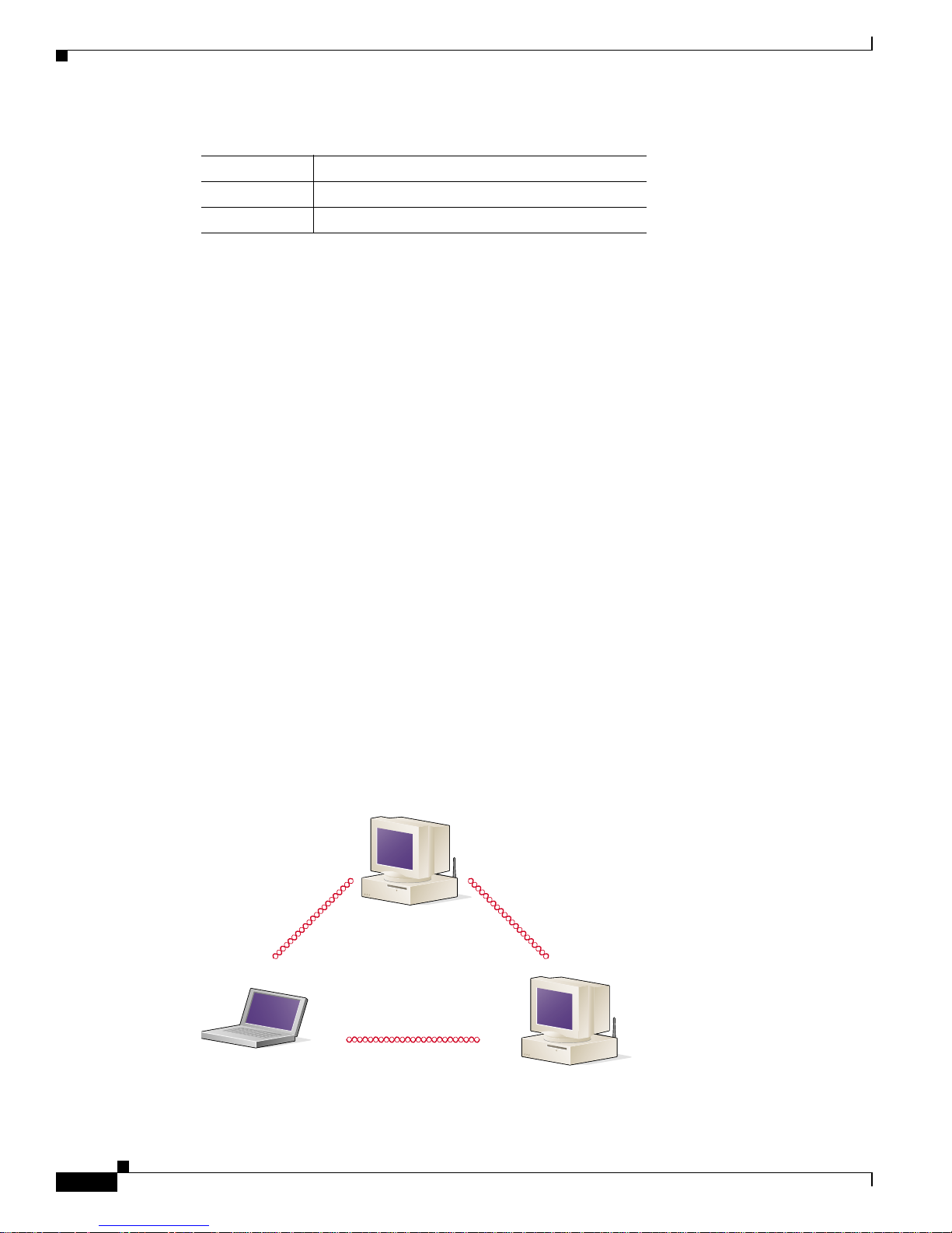
Ad Hoc Wireless LAN
An ad hoc wireless LAN (Figure 1-1) is the simplest wireless L AN configuration. In a w ireless LAN ,
using a n ad hoc n et wor k ope rat in g sy ste m (suc h as W i ndows for W ork gro ups) , al l de vi ces e quip pe d wit h
the PC C ar d can b e lin ked toge th er an d co mm u n ica te di re ctl y with e ach o th er
Figure1-1 Ad Hoc Wireless L AN
NDIS 2 MS-DOS , Windows 3 . xx
Packet MS-DOS, Windows 3 . xx
Table 1-1 Protocols Supported
Drivers Operating Systems
47520
Page 19
1-7
Cisco Aironet Wireless LAN Adapter s Inst all ation and Configuration Guide fo r MS-DO S
OL-1744-02
Chapter 1 Overview
System Configurati ons
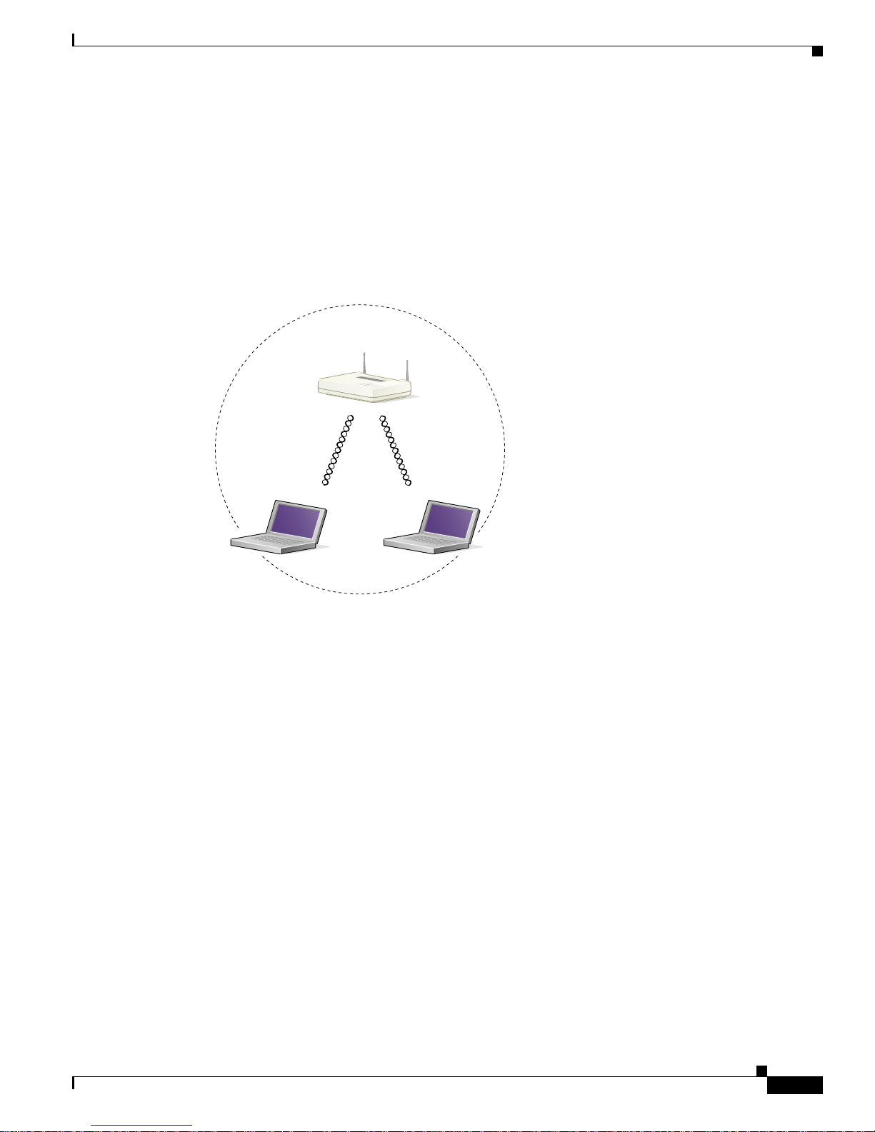
Wireless Infrastructure
In a wireless infrastructure (Figure 1-2), an access point is used as a stand alone root unit. The root unit
is not attached to any wired LAN (such as an Ethernet LAN), but func tions as a hub linking all stations
together. This co nfigu r ati on i s s imilar to t he ad h oc n etw or k , ex cep t th at th e access po i nt s erves as the
focal point for communications. This increases the effective communication range over the ad hoc LAN
because both s t ati o ns are not req ui re d to b e i n di re ct commu nication ra nge of each o th er.
Figure 1-2 Wireless Infra structure
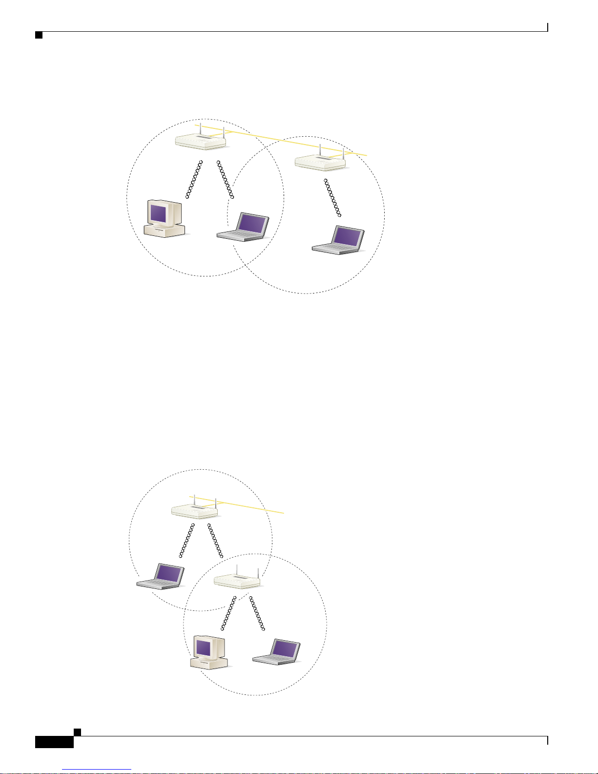
Wireless Infrastructure with Workstations Accessing a Wired LAN
A micro- ce llu lar netw ork ca n b e created by p lacing two o r m o r e ac ces s po in t s on a LAN ( Figure 1-3).
The roaming protocols allow remote workstations to move from one microcell dom ain to another. The
process is se am l es s and tra nsp ar en t. The c on n ect io n to th e file server o r h ost is m ai nt ain ed w i thout
disruption. This configuration is useful with portable or mobile stations, allowing them to be directly
connected to the wired network even while moving about (roaming). When an infrastructure is
configured by u s in g mul ti pl e a ccess poi nts an d r epe at er s, a mobile s tat io n is automati cally ass oc iat ed
and re-associated to the access point which provides the best performance. This is referred to as seamless
roam i ng.
Access Point
(Root Unit)
45834
Page 20
1-8
Cisco Aironet Wireless LAN Adapters Instal lation and Configuration Guide for MS- DO S
OL-1744-02
Chapter1 Overview
System Configurations
Figure 1-3 Wireless Infrastructure with W orkstations Accessing a Wir ed LAN
Extended Infrastructure Using Repeaters
An acces s p oi n t c an be configur ed as a s t an d- al one repeate r to ext en d th e r an g e o f yo u r in frastructu re ,
or to overco me an RF bloc ki ng ob stac le ( Figure 1-4). The r ep eat er f or war ds tr affic bet w een t he C isco
Aironet W ire less LAN Client Adapt er equip ped works tati ons and de vices and the wire d LAN by sendi ng
packets to either another repeater or to another access point attached to the wired LAN. The data is sent
through whichever route provid es the greatest performance for the client. Multiple repeater hops can be
support ed in the pa th to t he w ir ed L A N .
Figure 1-4 Extended Infrastr ucture Using Repeaters
Access Point
(Root Unit)
Access Point
(Root Unit)
45835
Wired LAN
Access Point
(Root Unit)
Access Point
(Repeater)
45836
Wired LAN
Page 21

1-9
Cisco Aironet Wireless LAN Adapter s Inst all ation and Configuration Guide fo r MS-DO S
OL-1744-02
Chapter 1 Overview
Coverage Options
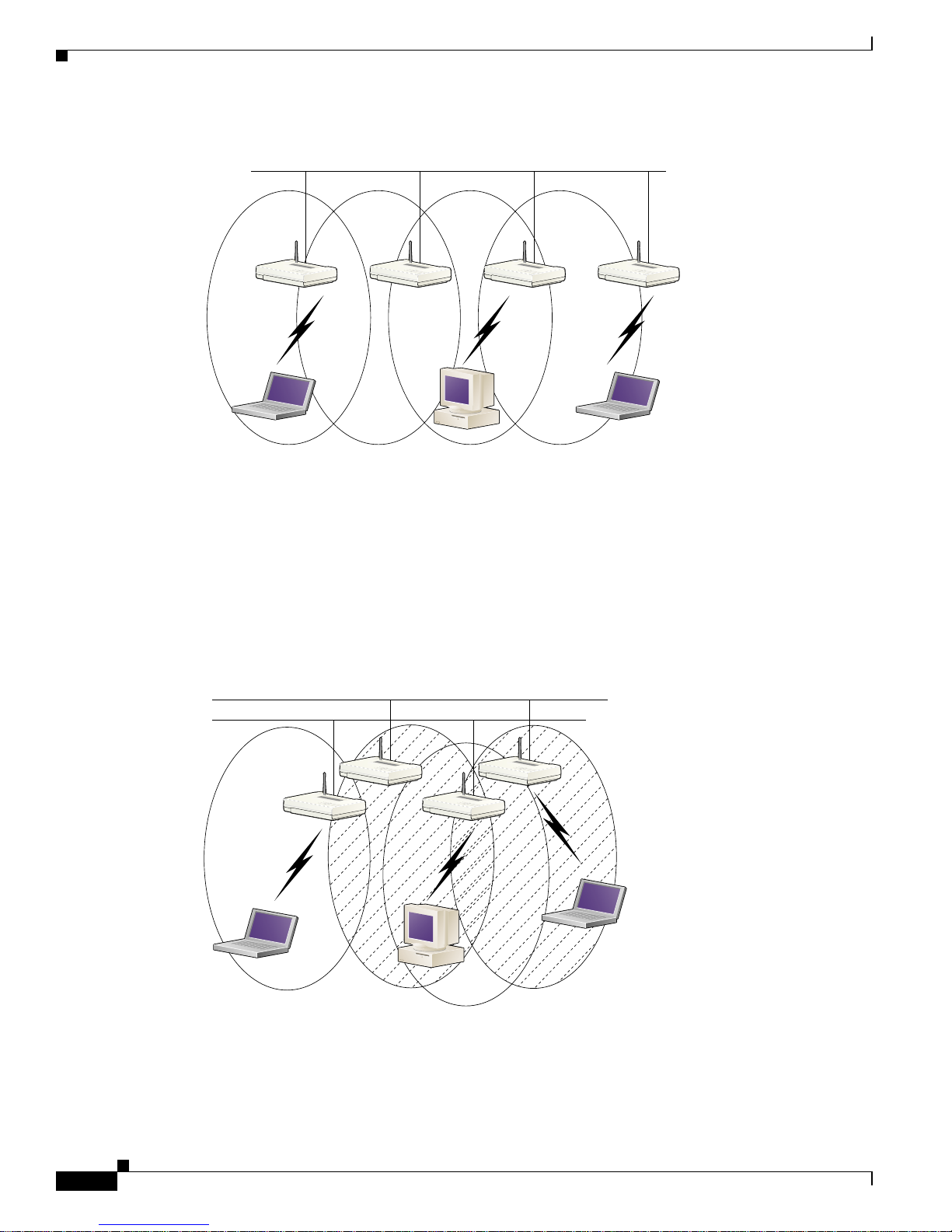
Coverage Options
The syste m architec tu re o pt io ns of t he w ir el ess st at io n a nd a ccess poi nts p rovid e fo r a variety o f
coverage altern ative s and fle x ib ility. The sy s tem ca n be desig ned to p r ovide a w i de coverage ar e a w i t h
minim al overl ap (Figure 1-5) or coverage with heavy overlap (Figure 1-6). The latter improves system
perform an ce an d p r o tec tio n ag ain s t down time in th e event o f a c omponent fa il ure.
Minimal Overlap Coverage
By arran g ing th e access p oi nt s s o th at th e overlap i n coverag e ar ea i s m i ni miz ed , a large ar ea can b e
covered with minim al s y stem cost (Fi gu r e 1 - 5). The total band w id th availa bl e t o e ach mobile s t ati o n
depend s on the am ou n t of data e a ch m ob ile sta ti on need s to t ransfer a n d t he number of st ations lo c a te d
in each cell. Seamless roaming is supported as a mobile station moves in and out of range of each access
point, thereby maintaining a constant connection to the wired LAN. Each access point (and adapter) must
be con fig ur e d w ith the same SS ID to prov ide the r oaming capabi lity.
Figure 1-5 Minimal Overlap Coverage Option
Heavy Over l ap C overage
By arranging the access points so that the overlap in coverage area is nearly maximized, a large number
of mobile stations can be supported in the same wireless infrastructure (Figure 1-6). However, units in
overlapping cove ra ge areas on the s ame frequen cy w ill d et ect adjacen t cell tra ffic and d ela y
transmi ssio ns that wo uld cau s e co lli s io n s. Th is reduce s th e aggregate r ad i o sy s t em t hr o ugh pu t. H eavy
cell overlap is not recommended for maximum system throughput. Due to the redundancy in coverage
overlap, syst em acc es s i s n ot lo st if an access p oi nt fa ils. If the access po in t fai ls, th e s t at io n
automat ic all y r oa m s to an o pe r ati on al access poin t. With this s y ste m ar ch ite ctu r e, al l access poi nt s and
PC Card units must be configured with the same SSID.
Wired LAN
65521
Page 22
1-10
Cisco Aironet Wireless LAN Adapters Instal lation and Configuration Guide for MS- DO S
OL-1744-02
Chapter1 Overview
Coverage O ptions
Figure 1-6 Heavy Overlap Coverage Option
Multiple Overlapping Systems Coverage
Multiple s y ste m s ca n op er at e i n th e same vic init y (Figure 1-7). The arch it ect ure provides m ul ti pl e
channels, which can exist in the same area with virtually no interference to each other. In this mode, each
system must be configured with different SSIDs and different channels, which prevent clients from
roam in g to acce s s points of a di fferent w ireles s s ystem .
Figure 1-7 Multiple Overlapping Systems Coverage Option
Wired LAN
65522
Wired LAN 2
Wired LAN 1
65523
Page 23

CHAPTER
2-1
Cisco Aironet Wireless LAN Client Ada pters Installation and Config ura ti on Gui de for MS- DO S
OL-1744-02
2
Installing the Hardware
This section describes the procedures for installing the Cisco Aironet Wireless LAN Client Adapter.
These to pics a re cove re d in th is sect ion:
• Safety Information, page 2-2
• Unpacking the Client Adapter, page 2-3
• Inserting the Client A d ap ter into a Comp ut in g D evice, pag e 2 - 5
• Removing the Client Adapter, page 2-7
Page 24

2-2
Cisco Aironet Wireless LAN Client Adapters Installation and Configuration Guide for MS-DOS
OL-1744-02
Chapter2 Installing the Hardware
Safe ty Information
Safety Information
Follow the guidelines in this section to ensure proper operation and safe use of the client adapter.
FCC Safet y Compliance Statem ent
The FCC, with its action in ET Docket 96-8, has adopted a safety standard for human exposure to RF
electromag n et ic energy em itt ed by FCC-cert ifie d eq uipment. Cis c o A ir onet produc ts m eet the
uncontrolled environmental limits found in OET-65 and ANSI C95.1, 1991. Proper operation of this
radio device according to the instruc tions in this publication will result in user exposure substantially
below the F CC r eco mm e nd ed l im i ts.
Safety Guidelines
• Do not touch or m ove the an ten na whil e the unit is tr an sm i tti ng or r ece ivin g.
• Do not hold any component containing a radio such that the ante nna is very close to or touching any
exposed pa rt s o f th e b o dy, especi al ly th e f ace or eyes, w hi le tr an sm it ti ng .
• Do not opera te th e ra di o o r attem p t to transmit dat a un les s the antenna is conn ec ted ; ot h er wi se, the
radio can be damaged.
• Use in specific environments:
–
The use of wireless devices in hazardous locations is limited to the constraints posed by the
safety directors of such environments.
–
The u se of w i r eless devices o n a i rplane s is gover ne d by the F ed e r al Aviation Admi nistration
(FAA).
–
The use of w ir el ess devi ces i n ho sp itals is r est ri ct ed to t he li m it s s et f orth by e ach h osp ital.
• Antenna use:
–
To comply with FCC RF exposure limits, dipole antennas should be located at a minimum
distance of 7.9 inches (20 cm) or more from the body of a ll persons.
–
High-gain, wall-mount, or mast-mount a ntennas ar e designed to be profess ionally installed and
should be located at a minimum distance of 12 inches (30 cm) or more from the body of all
persons. Please contact your professional installer, VAR, or antenna manufacturer for proper
installa tion req ui r em en t s .
Warnings
Observe th e fo ll owing w ar ni n gs w h en o p er ati ng t he client ad ap ter :
Warning
Do not operate your wireless network device near unshielded blasting caps or in an expl osive
environment unless the device has been modified to be especially qualified for such use.
Page 25

2-3
Cisco Aironet Wireless LAN Client Adapt er s Inst all ation and Configuration Guide fo r MS-DOS
OL-1744-02
Chapter 2 Installing the Hardware
Unpacking the Client Ada pter
Warning
In order to comply with RF exposure limits established in t he ANSI C95.1 standards, it is
recommended when using a laptop with a PC card client adapter that the adapter ’s integrated
antenna is positioned more th an 2 inches (5 cm) from your body or nearby persons during extended
periods of transmitting or operating time. If the antenna is positioned less than 2 inches (5 cm) from
the user, it is recommended that the user limit exposure time.
Translated versions of these safety warnings are provided in Appendix D.
Other Devic es in the Wireless Network
Refe r to the use r’s guide and techn ical reference manual for the access point, universal client, or bridge
for additional information.
Unpacking the Client Adapter
Follow these s t ep s to u n pa ck th e client a da pt e r:
Step 1 Open th e sh ip p in g co nt ain er, and car ef u ll y r em ove t he co n ten ts.
Step 2 Return all pa cking m aterial s t o the sh ippin g c on t a iner, and s ave it.
Step 3 Ensure th at all it em s li sted in the “Package Contents” section are included in the sh ipment. Check each
item fo r da m ag e.
Note If any item is damaged or missing, notify your authorized Cisco sales representative. Any remote
antenna a nd i ts a s soc iat ed w iring are s hi pped s e pa ra tel y.
Package C ontents
Each client adapter is shipped with the following items:
• Cisco Aironet PC Card Client Adapter, Cisco Aironet LM Card Client Adapter, or Ci sco Aironet
PCI Client Adapter
• 2-dBi dipole antenna (for PCI client adapter)
• Quick Start Guide: Cisco Aironet Wireless LAN Client Adapters
• Cisco Aironet Series Wireless LAN Client Adapters Drivers and Utilities CD
• Cisco product registration card
Note The MS- D O S d river s and util ities ar e n ot shipped with t he adapter. Follow this p ath to downl oad
them from Cisco.c om : Service & Support > Technical Assistance Center > Software Center >
Wireless Software.
Page 26
2-4
Cisco Aironet Wireless LAN Client Adapters Installation and Configuration Guide for MS-DOS
OL-1744-02
Chapter2 Installing the Hardware
Unpacking the Client Adapter
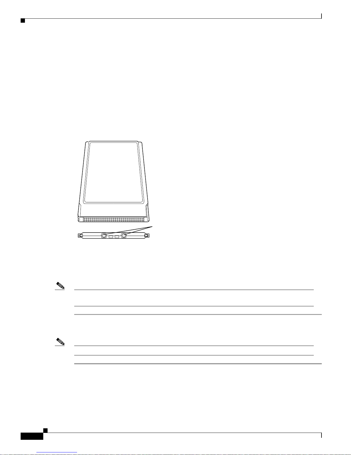
Antenna Co nnectors
The LM card version has two female MicroMate (also called MMCX ) antenna connectors on one end.
See Figure 2-1. All antennas and cables attached to the adapter must be equipped with male MicroMate
connecto rs .
The two an te nn a co nn ec to rs allow a Diversi ty A n ten n a o r tw o sep ar at e an te nn as to be a ttached to t he
Cisco Air o ne t Wire l ess L AN A da pt er . W h en t wo an te nn as are con ne cte d, the adap ter a ut omatically
select s antenn as t o provide t h e strongest si gn a l f or r a d io o perati on s . This f e a ture im pr ove s packet
delivery and system throughput by avoiding reception and tra nsmission instances that are hampered by
RF multipath signals or blocking structures in the envi ronment.
Figure 2-1 LM Adapter Antenna Connections
Attachi ng a Remote Antenna
Note The PCM vers io n o f the adapte r co mes w i th th e an ten n a in s t all ed . I f yo u n eed to re m ove o r ch an ge
the antenna, remove the adapter from the PC card slot.
Step 1 Line up the antenna cable leads with the connectors on the adapter.
Step 2 Slide th e c ab le leads in to th e co nn ec tors unti l t h ey s n ap in t o p l ace.
Note The J1 port is the primary port. If the antenna has only 1 MMCX connector, attach it to the J1 port.
MicroMate
Antenna
Connectors
J1 J2
Page 27

2-5
Cisco Aironet Wireless LAN Client Adapt er s Inst all ation and Configuration Guide fo r MS-DOS
OL-1744-02
Chapter 2 Installing the Hardware
Inserting the Client Ada pter int o a Comp uti ng Devi ce
Detaching a Remote Antenna
Step 1 Remove the adapter from the PC card slot.
Step 2 Grasp th e e nd o f th e a nt en na cable lead by the conn ec to r.
Step 3 Gently p u ll th e c on n ect or aw ay fro m t he ad ap ter until it com es f r ee.
Inserting the Clien t Adapter into a Computing Device
This section provides instructions for inserting a PC card or a PCI client adapter into a computing device.
Caution These pro cedure s and th e phys ical conn ectio ns the y de scribe a pply g eneral ly to co n venti onal P C card
slots and PCI expansion slots. In cases o f custom or nonconventi onal equipm ent, be alert to possible
differences in PC card slot and PCI expansion slot configurations.
Inserting a PC Card
Step 1 Befo re you begin, examine the PC card. One end h as a dual-row, 68-pin PC ca rd connector. The card is
keyed so th at it can b e i nserted o nl y on e way i nt o th e PC card slot.
Step 2 Turn on your computer, let the operating system boot up completely, and follow the remaining steps in
this sectio n to inse rt the PC card.
Caution Do not force the PC card into your computer’s PC card slot. Forcing it will damage both the card and
the slo t. I f the PC car d do es no t in s er t e a si ly, remove the card an d r ein s er t it .
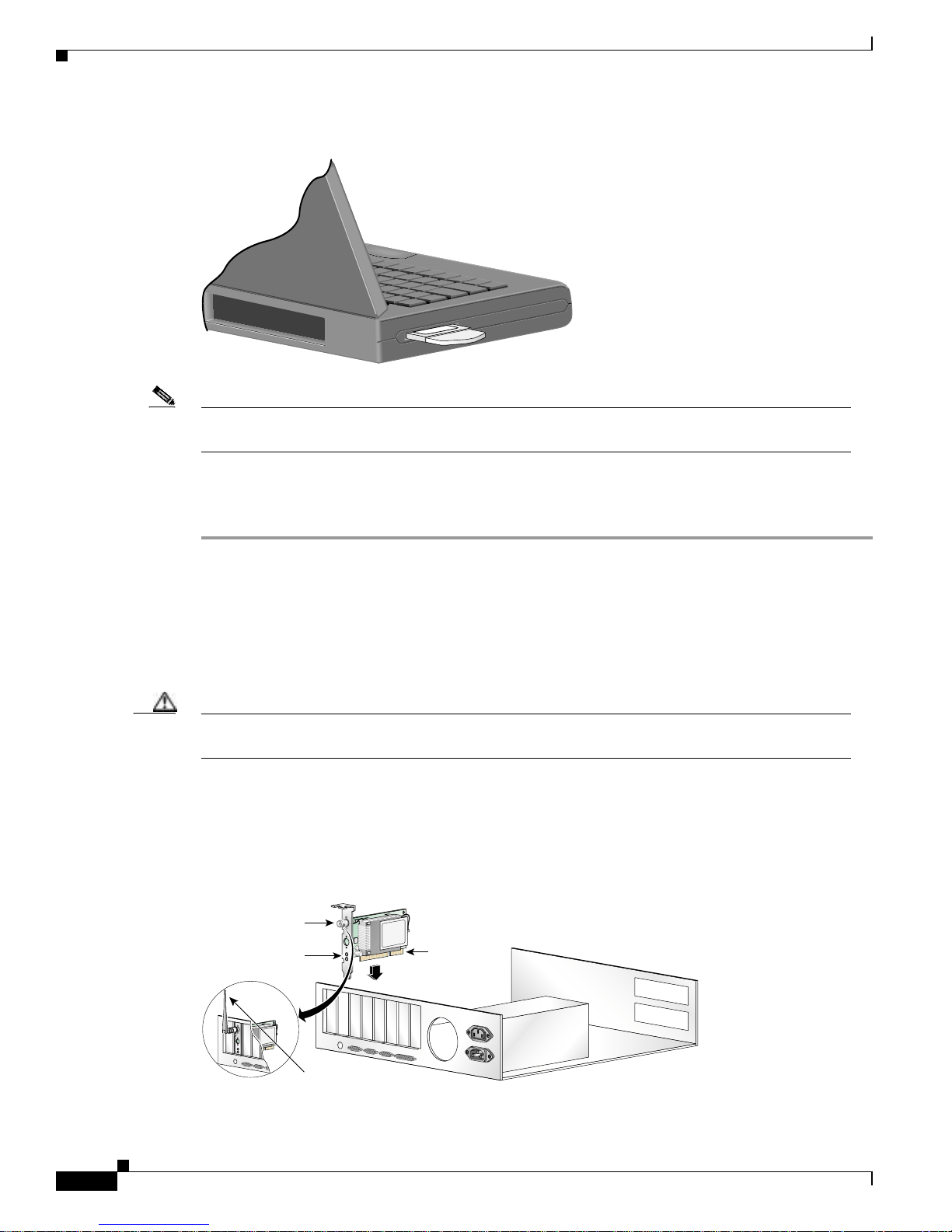
Step 3 Hold the PC ca rd wi th the Cisc o lo g o fac in g u p and in se rt it int o th e P C ca rd s lo t, ap pl yi n g jus t en oug h
pressure t o m ak e su r e it i s ful ly seated. Se e Figure 2- 2.
Page 28
2-6
Cisco Aironet Wireless LAN Client Adapters Installation and Configuration Guide for MS-DOS
OL-1744-02
Chapter2 Installing the Hardware
Inserting th e Cl ient Ad ap t e r into a Computing Device
Figure 2-2 Inserting a PC Card into a Computing Devi ce
Note You can remove and reinsert your PC card when necessary. See the “Removing the Client Adapter”
section on page 2-7 for instructions.
Inserting a PCI Client Adapter
Step 1 Turn off the PC and all its components.
Step 2 Remove th e compu t er cover.
On most Pentium PCs, PCI expansion slots are white. Refer to your PC documentation for slot
identifica tio n.
Step 3 Remove the screw from the top of the CPU ba ck panel above an empty PCI expansion slot. This screw
holds t he metal bracke t o n the bac k panel.
Caution Static el ect ri ci ty can d amage you r cl ie nt ad ap te r. Before r em ovin g th e adapter fr om the ant istatic
packa g in g, disc h arge sta t ic by touchi ng a met al part o f a grounde d P C .
Step 4 Examine th e client ada pter . Th e an ten n a c on n ect or and the LED s f ace out of you r c om pu te r an d are
visible when you put the cover back on. The bottom edge of the adapter is the connector that you will
insert into an empty exp ansio n slot in you r comp uter. See Figure 2-3.
Figure 2-3 Inserting a PCI Cl ient Adapter into a PC
Antenna
connector
LEDs
Card edge
connector
Standard 2 dBi
dipole antenna
47521
Page 29

2-7
Cisco Aironet Wireless LAN Client Adapt er s Inst all ation and Configuration Guide fo r MS-DOS
OL-1744-02
Chapter 2 Installing the Hardware
Removi n g th e Client Ad apter
Step 5 Tilt the adap ter t o allow the a nt en na co nn ec to r an d LED s t o slip thro ug h th e openin g in t he CP U back
panel.
Step 6 Press the client ada pt er i nt o th e empty slo t u n ti l t he co nn ec to r is firmly sea ted .
Caution Do not force the adapter into the expansion slot as this could damage both the adapter and the slot.
If the adap ter does no t in s er t e asil y, remove t he ad ap ter a nd r ei nsert it.
Step 7 Reinsta ll the screw on the CPU back panel, an d replace the compu ter cover.
Step 8 Attach th e 2-dBi an tenna to the adapt e r’s antenna connector until it is finger-tight. Do not overtighten.
Step 9 For optimal reception, position the antenna so that it is straight up.
Step 10 Boot up your computer.
Note Because PCI a dapt er s a re i nst al led in sid e de skt op co mput ers , yo u s houl d hav e l itt le r ea son t o r emo ve
the adapter. However, instructions are provided in the “Removing the Cl ient Adapter ” section on
page 7-7 in case you ever need to remove your PCI client adapter.
Removing the Clien t Adapter
Follow the in s t ructions in th is s ect io n w he never yo u n eed t o re m ove t h e cl ie nt ad ap ter from y ou r
computer.
Removing a PC Card
To remove a PC card after it is successfully installed and configured (such as when your laptop is to be
transported), pull the card directly out of the PC card slot. The client adapter is “hot swap pa ble” an d ca n
be inserted and eje cted at any ti m e af ter y o u h ave i nst all e d th e dr iver.
Removing a PCI Client Adapter
Beca u se a PCI adapters are insta l led inside desktop co mputers, which are not designed for portable use,
you should have little reason to remove the adapter. Follow these steps in case you ever need to remove
your P CI c lient adap ter.
Step 1 Completely shut down your computer.
Note When the computer is turned off by using the power swit ch, there still might be power supplied to
the motherboard. To ensure that your computer is completely shut down, unplug the computer’s
power c o r d fr om its power source .
Step 2 Discon ne ct the clie nt ad ap ter’s antenna.
Step 3 Remove th e compu t er cover.
Page 30

2-8
Cisco Aironet Wireless LAN Client Adapters Installation and Configuration Guide for MS-DOS
OL-1744-02
Chapter2 Installing the Hardware
Removing the Client Adapter
Step 4 Remov e the sc rew fro m the t op of th e CPU bac k panel a bove the P CI expa nsion sl ot th at hold s your cl ient
adapter.
Step 5 Pull up firmly on the client adapter to release it from the slot, and carefully tilt the adapter to allow it to
clear the op en in g in t he C P U ba ck p an el.
Step 6 Reinsta ll the screw on the CPU back panel, an d replace the compu ter cover.
Page 31

CHAPTER
3-1
Cisco Aironet Wireless LAN Client Ada pters Installation and Config ura ti on Gui de for MS- DO S
OL-1744-02
3
Installing the Software
This chapter provides instructions on how to install the PACKET, NDIS2, NDIS3 and ODI drivers
operating under MS-DOS, Windows 3.x, and Windows for Workgroups
These to pics a re cove re d in th is sect ion:
• Driver Overview, page 3-2
• Windows for Workgroups 3.11 NDIS2 Installation, page 3-3
• DOS NDIS2 Installation, page 3-3
• ODI Driver Install atio n, page 3-5
• Additional Requirements and Features, page 3-5
• Driver Keywords and Settings, page 3-6
Page 32

3-2
Cisco Aironet Wireless LAN Client Adapters Installation and Configuration Guide for MS-DOS
OL-1744-02
Chapter3 Installing the Software
Driver Overvi ew
Driver Over view
This sectio n c ove r s t he drivers . T h e utili ti es are dis c u ss ed in Ch ap te r 4, “U tilitie s. ”
The MS-D O S an d Windows for Workgroups b ased drivers mu st h ave a co nfigu r ati on fi le cr eat ed ( or
edited) with an A SCII text ed itor.
The drivers and associated files do not ship with the adapter. You must download them from the Wireless
Software Center at Cisco.com. The downloadable file, DOSDRVS.EXE, is a self-extracting executable
file containing separate self-extracting executa ble files for e ach driver. After downloading and running
the DOSDRVS.EXE file, you can run the driver file for your specific application. You must also run the
UTIL.EXE to ext ract the utility prog r ams for th ese d rivers. Th e s tru ctu r e of th e DO S DRVS.EXE file is
shown in Table 3-1.
Table 3-1 DOSDRVS.EXE File Structure
Filename Description
DOSDRVS.EXE A self-ex tr ac tin g execu table file co ntain in g th es e s el f-ex tr act in g
executable files :
• PKT.E XE—packet driver and files
• ODI.EXE—ODI dr iver an d files
• NDIS.EXE—NDIS2 driver and files
• UTIL.EXE—configuration and diagnostic utilities
• DOSINST.PDF—Cisco Aironet Wireless LAN Client Adapters
Installation and Configuration Guide for MS-DOS in portabl e data
file f o rmat
PKT.EXE Files
CSCPKT.COM Packet driver
CSCPKT.INI Sample initialization file
READ1ST.TXT Text file containing driver and installation notes
ODI.EXE Files
CSCODI.COM ODI driver
NET.CFG Sample i ni ti a li zat io n file
READ1ST.TXT Text file containing driver and installation notes
NDIS.EXE Files
CSCNDIS2.DOS NDIS driver
PROTOCOL.INI Sample initialization file
READ1ST.TXT Text file containing driver and installation notes
UTIL.EXE Files
AW C A LLI D .E XE Establi she s a call id nu mb er
PCMCI A .C O M Turns the PC M CI A s l ot on o r off to al low u til ities to acc es s t he adapter
RADINFO.COM Displays the adapter’s radio stat isti cs
WEP DO S . E X E S ets a W E P t ransm it key and k ey va l ues
Page 33

3-3
Cisco Aironet Wireless LAN Client Adapt er s Inst all ation and Configuration Guide fo r MS-DOS
OL-1744-02
Chapter 3 Installing the Software
Windows for Workgroups 3. 11 NDIS2 Installation
Windows for W orkgroups 3.11 NDIS2 Installation
Step 1 Power on your computer, and start Windows for Workgroups.
Step 2 Extract the NDIS.EXE files to the directory containing the network files on your computer’s hard drive.
Step 3 Go to the Network progra m group, and click Network Set-Up .
Step 4 Under Network Setup, choose Networks.....
Step 5 Under Networks, choose Install Microsoft Windows Network. Click OK.
Step 6 Under Network Setup, choose Drivers....
Step 7 Under Network Drivers, choose Add Adapters.
Step 8 If the d rivers a r e already c op ie d to th e hard d isk , t hey are di spl ay ed in the list.
Step 9 Under Add Adapter, choose the appropriate Cisco Aironet Adapter. If it is not on the menu list, choose
Unlis te d or Updated Network Driver. Choose the correct Cisco Aironet Adapter, and click OK.
Step 10 If the cho s en ad ap te r is d isp layed in th e Ne t wo rk Dr iv ers , click Setup.
Step 11 Select the appropriate parameters, such as Infrastructure Mode, SSID, Channel, and Bitrate.
Step 12 Exit Windows for Workgroups.
Step 13 To modify t he PC Card sys te m p ar am e ter s , ed it the PROTOCOL .I N I fi le in th e Windows director y.
Step 14 Reboot your computer.
DOS NDIS2 Instal lati on
The Cisco Aironet Wireless LAN Adapter can be installed in a NetBIOS-com pliant MS-DOS
environment such as MicroSoft LAN Manager or PC LAN. The installation of this driver includes
creating or editing a configuration file (PROTOCOL .IN I) .
This file m u st conta in th e lin es s how n in Table 3 -2.
Table 3- 2 Minimum PROTOCOL.INI Driver Settings
Infrastructure Mod e Ad Hoc Mode
[CSCNDIS2] [CSCNDIS2]
DRIVERNAME = CSCNDIS2$ DRIVERNAME = CSCNDIS2$
INFRASTRUCTURE = YES
If omitted, default is YES
INFRASTRUCTURE = NO
SSID = <your SSID> SSID = <your SSID>
CHANNEL = <channel>
Page 34

3-4
Cisco Aironet Wireless LAN Client Adapters Installation and Configuration Guide for MS-DOS
OL-1744-02
Chapter3 Installing the Software
DOS NDIS2 Insta lla tio n
Additio n al var i ab les defi ned in th e following s e cti on can als o b e us e d. Follow the s e steps to instal l t he
driver.
Step 1 Power on your computer.
Step 2 Extract the NDIS.EXE files to the directory containing the network files on your computer’s hard drive.
Step 3 Copy the PROTOCOL.INI file to the network directory or merge statements from the Cisco Aironet
supplied file into your existing PROTOCOL.INI file .
Step 4 Modify the CONFIG.SYS file. After the line containing: Device = PROTMAN.DOS, add
Device = [drive:] [path] CSCNDIS2.DOS.
Step 5 To modify the PC Card s ystem parameters, edit the PR OTOCOL.INI file in the network directory . For a
list of parameters that can be modified, see Table 3-2.
Step 6 Reboot your computer.
DOS Packet Driver Installation
The instal lat io n of t hi s d river in cl ud es cr eat in g or e di ti ng a configur ati on fi le (C S CPK T.INI). T hi s fil e
must c on ta in th e lines show n in Table 3-3.
Additional variables defined in the following section can also be used.
The Wireless L AN Adap ter can be in stal led in a MS - D OS enviro nm ent by u sin g M S -DO S I P st ack
products such as FTP software.
Follow thes e st ep s to i nst all the d river.
Step 1 Power on your computer.
Step 2 Extract the PKT.EXE files to the directory containing the network files on your computer’s hard drive.
Step 3 Make sure that th e C S C P KT.INI file is i n th e d ir ec to r y c on ta in in g th e P ack et dr iver.
Step 4 If you wo ul d like to m o di fy t he PC Ca rd s y stem par am e ter s , ed it the CSC P KT.INI file. Fo r a l is t o f
parameter s th at can be m o dified , see Table 3.3 .
Step 5 Load the driver by ty ping CSCPKT [-cinuw] <int_number> at the MS -D O S pro m p t (f or ex amp le,
CSCPKT 0x65) and press Enter.
Table 3- 3 Minimum CSCPKT.INI Driver Settings
Infrastructure Mod e Ad Hoc Mode
[CSCPKT] [CSCPKT]
INFRASTRUCTURE = YES
If omitted, default is YES
INFRASTRUCTURE = NO
SSID = <your SSID> SSID = <your SSID>
CHANNEL = <channel>
Page 35

3-5
Cisco Aironet Wireless LAN Client Adapt er s Inst all ation and Configuration Guide fo r MS-DOS
OL-1744-02
Chapter 3 Installing the Software
ODI Driver Installation
Note Options -c, -i, -n, and -w are unused in this version of the driver and are provided for backward syntax
compatibility.
Note <int_number> is an interrupt vector location in the range 0x60 to 0x7F.
Note To unloa d t h e d river, enter CSCPKT –u <int_number> (for example, CSCP KT –u 0x 65) . The
<int_n umber> value mus t b e the sa me value used when you instal le d the d r iver.
Step 6 Load the MS- D O S I P st ack .
ODI Driver Installation
The PC C ar d can b e i ns tal led i n an O D I co mpl ia nt M S -DO S environment s uc h as N ove ll N etWare.
Follow thes e st ep s to i nst all the d river.
Step 1 Power on your computer.
Step 2 Extract the CSCODI.COM files to the directory containing the network files on your computer’s hard
drive.
Step 3 Copy the NET.CFG file, or merge the Cisco Aironet supplied NET.CFG file into your existing NET.CFG
file in the network directory.
Step 4 Modify the adapter’s system parameters by editing the NET.CFG file. The following parameters can be
modified (INFRASTRUCTURE mode only):
• INFRASTRUCTURE = YES (If omitted, default is YES)
• SSID = <your SSID>
Step 5 Run the ba tch fil es created by th e N e tWare instal lat io n di s ks , o r m an ua ll y lo ad th e d r iver fr o m
AUTOEXEC.BAT or the command line. This can be done by running LSL, followed by CSCODI,
IPXODI, and NETX or VLM.
Additional Requirements and Features
The following INI and CFG file lines might appear anywhere within a section. Only the sections
containing t hese lines wi ll be pa r s ed:
• CSCPKT.INI file can have a s ec tio n h ead er o f [ CS C PK T] .
• PROTOCOL.I N I file can have any s ect io n he ad er, but th e section m us t co n tai n th e k eywor d an d
para me ter D RIVER NAME = C S CNDI S 2 .
• NET.CFG file must have a section header of Link Driver CSCODI.
Page 36

3-6
Cisco Aironet Wireless LAN Client Adapters Installation and Configuration Guide for MS-DOS
OL-1744-02
Chapter3 Installing the Software
Driver Keywords and Settings
The follow ing gen e r al in fo r m at io n is p er ti nent:
• Multiple sections are supported.
• Blank lin es are sup po r ted .
• Comments begin with semicolon and can appear anywhe re on a line.
• Keywords can be uppercase or lowercase and can be surrounded by white space if desire d.
• Any parameter or variable that can be set to ON or OFF can also be set to YES or NO, respectively.
• Any parameter that begins with 0x will be assumed to be hexadecimal. Any parameter that begins
with a digit (excluding the 0x case) will be assumed to be decimal. Any parameter that begins with
quotes wi ll be assumed to be a quoted string parameter. Any other parameter wil l be assumed to be
an unquoted string parameter.
• For stri ng pa ramet ers , doub le quote s ar e requ ir ed aro und the s tring if t he stri ng c onta in s any s pec ial
characters .
Note The PROTOCOL.INI file does not support some of the white space characters in a quoted string. If
a string b egin s w it h a n alp h ab eti c c ha ra cter and co nt ain s n o sp eci al ch ar act er s , t he quo tes can be
omitted .
• For Pac ket string parameters, the string can be enclosed with double quotes or single quotes. If a
string is qu o ted , a ny ch aract er exc ep t a “null” and the quote delimiter itself can occur between the
quotes.
Note If doubl e q u ot es are used fo r a delim ite r, a sin g le qu o te can ap p ear i n th e st ri ng , an d vi ce v er sa. I f
the strin g beg ins w it h a n alp h ab eti c c ha ra ct er an d co nt ain s n o s p eci al ch ar act er s, t he q uo te s ca n b e
omitted .
• For numeric parameters, the value can be hexadecimal or decimal. Hexadecimal numbers must be
preceded w it h th e c ha ra cters 0x but all characters can be uppercase or lowercase.
Driver Keyword s and Settings
The def au lt P C C ar d config ur at io n is set to:
• Constant Awake Mode.
• Infrastructure Mode—allows association with any access point matching the SSID supplied by the
user.
• The factory-supplied network address.
• Receive direc ted p ac ket s to t his ad d re ss as we ll as multicast s an d br o ad casts.
• Retry data packets up to 16 times before discarding the frame.
• Retry RTS sequ en ce u p t o 16 t imes befor e di scar d in g th e f r ame.
• RTS exchange on a ll f ra mes g reat er t ha n 3 0 0 bytes.
• Fragment frames longer than 700 bytes.
• Discard fragmented transmit pack ets if not delivered in 5 seconds.
• Discard fragmented receive frames if not co mplete after 10 seconds.
Page 37

3-7
Cisco Aironet Wireless LAN Client Adapt er s Inst all ation and Configuration Guide fo r MS-DOS
OL-1744-02
Chapter 3 Installing the Software
Driver Keywords and Settings
• Active scanning with 3-Kusec energy detect time and 20-Kusec probe response wait timeout.
• Rescan i f 8 be aco ns are cons ec ut ively m isse d.
• Send an access po int keep - alive m es sag e every 10 seco nd s.
The following tables contain keywords and parameter settin gs common to both the NDIS2
PROTOCOL.INI, ODI NET.CFG, and the PKT CSCPKT.INI configuration files.
Basic Syste m P aram eters
Basic syst em op er at io n can b e adjusted w it h th e f o ll owing p ar ameters.
Table 3-4 Ge n era l N e tw o rk Parameters
Parameter (Keyword) Value Description
INFRASTRUCTURE ON, YES
OFF, NO
(Optional)—Specifies whether system
operation uses an infrastruc ture or
peer-to-peer/ad hoc network.
Default: ON, YES
SSID 1–32 ch ar ac ter st ri n g Identifies t he service s et id en ti fier o f th e
specific wireless network you are connected
to.
This parameter must match the syst em SSID.
NODENAME 1–16 character string (Optional)—Specifies a readable name for the
station.
NET ADDRESS Any IEEE MA C addre ss
except broa dc ast and
multic as t
(Optional)—Allow s f or locally ad m in ist er ed
MAC addresses by overriding the unique
MAC ID on t h e ad ap te r.
NODE ADDRESS Same as NETADDRESS (ke yword valid only
in NET.CFG file).
RXMODE NORMAL
UNICAST
NOMULTICAST
(Optional)—Deter mines wh at frames are
delivered to the driver from the adapter.
Normal m eans unica st, mu lticas t, and
broadca st f r am e s ar e received.
Default: NORMAL
DATARATE1 0–255 (Optional)—Spec ifies the ra te at whi ch the
adapter communicates with the access point to
which it associates.
Default: 1–11
This s et tin g m u s t m a tc h th e access p oi nt ’s
setting.
DATARATE2 0–255
Page 38

3-8
Cisco Aironet Wireless LAN Client Adapters Installation and Configuration Guide for MS-DOS
OL-1744-02
Chapter3 Installing the Software
Driver Keywords and Settings
Network Performan ce V ari ab l es
Network p e rf or man ce can be optimi zed w it h th e f o ll owin g var iables.
Table 3-5 Advanced Network Variables
Variable Value Description
LONGRETRYLIMIT 0–255 (Optional)—Spec ifie s th e nu m b er o f ti m es an
unfragmented packet is retried before it is dropped and
a transm it er r o r is r ep ort ed to the driver.
Default: 16
SHORTRETRYLIMIT 0–255 (Optional)—Specifies th e number o f times a
fragmented packet is retried to gain access before it is
dropped an d a transmi t error is repo rted to th e driver.
Default: 16
RTSTHRESHOLD 0–2312 (Optional)—specifies the minimum frame size in bytes
for which RTS/CT S delivery are u se d . Packets l on ger
than the specified value are delivered by using
RTS/CTS handshaking.
Default: 300
TXMSDULIF ETIM E 0 –0xFFFF (Optional)—Spec ifies the m axim um tim e to attem pt
packet delivery.
Default: 5000 kus (5 seconds)
RXMS DUL IFETIME 0–0xFFFF (Optional)—Specifies the maximum time for receiving
a fragmented packet.
Default: 10000 kus (10 seconds)
TXPOWERLEVEL 0–100 (Optional)—Selects the programmed transmit power
level in mW, which can vary per country.
DIVERSITY DEFAULT
ON
RIGHT
LEFT
(Optional)—Specifies the transmit or receive diversity
method u s ed by t he ad ap ter.
Default = Divers ity i s tu r ned on
On = Adapter uses both antennas
Right = A da pter u ses t he an te nn a a tt ach ed t o j ack 1
Left = A da pt er u s es t he an tenna attach ed to j ack 2
Default: ON
LEAP ON (YES)
OFF (NO)
(Optional)—turns LEAP (Cisco’s version of
Extens ible Au thent ication P r ot ocol) on or off.
Default: OFF
Page 39

3-9
Cisco Aironet Wireless LAN Client Adapt er s Inst all ation and Configuration Guide fo r MS-DOS
OL-1744-02
Chapter 3 Installing the Software
Driver Keywords and Settings
Fragmenta t i on V ari ables
Additional system performance adjustments can be made with the following group of variables.
WORLDMODE ON (YES)
OFF (NO)
(Optional)—Allow s th e ad ap ter t o au to m at ica lly
inherit channel configuration and output power
propert ie s fr om th e ac c ess p oin t t o w hi ch it as soci a tes .
Default: OFF (NO)
Enable World mod e w he n t he ad ap te r ne ed s to
automa ti cal ly m at ch t he country configur at io n of t he
access po in t to w h ich i t associat es.
SHORTPREAMBLE 0, 1, 2 (Optional)—Establis h es t he length o f th e p a c ket ’s
synchronization bit.
Default: 0
0 = Automatic
1 = Long preamble
2 = Short preamble
Table 3-5 Advanced Network Variables (continued)
Variable Value Description
Table 3-6 Fragmentation Variables
Variable Value Description
FRAGTHRESHOLD 256–312
(must be an even value)
(Optional)—Spec ifie s th e fragme nt ati on s i ze
in bytes. Fr ames long er th an t he sp ecified
value are t ra nsmitted u s in g mu ltiple pa cket s.
Default: 700
Page 40

3-10
Cisco Aironet Wireless LAN Client Adapters Installation and Configuration Guide for MS-DOS
OL-1744-02
Chapter3 Installing the Software
Driver Keywords and Settings
Power Management Variables
The Wireless L AN Ad ap t er pow er m a na ge m en t can b e a dj ust ed w it h th e f o ll owing g ro u p of variables.
Table 3-7 Power Management Variables
Variable Value Description
POWERSAVEMODE CAM
PSP
FASTPSP
(Optional)—Establishe s the ope rating method
the device uses to conser ve electric a l pow e r.
CAM = Constant Awake Mode
PSP = Power Save Mode
FASTPSP = Fast Power Save Mode
Default: CAM
In ad hoc m o de , i f th e POWE R SAVEMODE
is PSP or FASPSP, the ATIMDURATION
variable mus t be a no n-zer o value.
CAM kee ps the client adap te r power ed u p
continuously so there is little lag in message
response time. This mode consumes the m ost
power but offers the highest throughput.
PSP powers the adapter on and off based on a
time al go r ith m. When retr ievi ng p ack ets , th e
adapter remains in PSP mode and manages
only the amount of traffic within the time
period wh en it i s sch edule d on. Wh en t he ti me
expires, the adapter turns off for the required
time an d th en tu r ns ba ck on again to r et rieve
more data.
FASTPSP switches between a PSP mode and
CAM, depending on network traffic. This
mode sw i tches to C AM wh en r et rievin g a
large number of packets and switches back to
PSP after the packets have been retrieved.
MAXPOWERSAVE ON (YES)
OFF (NO)
(Optional)—Turns Maximum Power Save
mode on or off.
Default: OFF
MAXPOWE RSAVE causes the access poi n t
to buffer in comin g m es s ages f or the c l ie n t
adapter, which wakes up periodically and
polls th e access po i nt to see if any buffered
messag es are waiting fo r it . Th e adapter can
request each message and then go back to
sleep.
MAXPOWERSAVE conserves the most
power but offers the lowest th rou ghput . Is
recom mended fo r devices fo r which p ower
consumptio n is the u ltimate conc e r n ( s u ch a s
small battery-powered devices).
Page 41

3-11
Cisco Aironet Wireless LAN Client Adapt er s Inst all ation and Configuration Guide fo r MS-DOS
OL-1744-02
Chapter 3 Installing the Software
Driver Keywords and Settings
ATIMDURATION Between 0 and less than
the be aco n in terval
(Optional)—Spec ifie s th e len g th o f time for
ATIMs following a beacon.
Defau lt: 5 Kusec
Constant Awake Mode is 0.
In ad hoc mode, th is va lue must be non-zer o if
POWERSAVEMODE is PSP or FASTPSP.
This value i s u sed o nl y wh en st ar ti ng a new
network. When joining a network, the value
currently in use is adopted.
SLEEPFORDTIM ON (YES)
OFF (NO)
(Optional)—Allows the no de to slee p throu gh
DTIMs for ex tra power saving. Bro adcast and
multic ast traffic mig ht be miss ed.
Default: OFF
Used only in INFRASTRUC TURE mode
when POWERSAVE mode is PSP or
FASTPSP.
LISTENTIME 0–0xFFFF (Optional)—Determin es how ofte n to awak en
for beacons.
Default: 200 Kusec (200 ms)
Used only in INFRASTRUC TURE mode
when POWERSAVE mode is PSP or
FASTPSP.
The PC c ar d alw ay s awaken s to receive
DTIMs when in PSP Mode, unless sleep for
DTIMs is set.
FASTLISTENTIME 0–0xFFFF (Optional)—Determin es how ofte n to awak en
for beacons.
default: 100 Kusec (100 ms)
Used only in INFRASTRUC TURE mode
when POWERSAVE mode is PSP or
FASTPSP.
The PC C ar d alway s awa kens to receive
DTIMs when in FA STPSP Mode.
Table 3-7 Power Management Variables (continued)
Variable Value Description
Page 42

3-12
Cisco Aironet Wireless LAN Client Adapters Installation and Configuration Guide for MS-DOS
OL-1744-02
Chapter3 Installing the Software
Driver Keywords and Settings
Scanning V ari ab l es
Additional system performance adjustments can be made with the following group of variables.
LISTENDECAY 0–0xFFFF (Optional)—Specifies the rate at whi ch the
listen in terval gr ows.
Default: 2
Used only in INFRASTRUC TURE mode
when POWERSAVE mode is PSP or
FASTPSP.
Listen interval begins at FASTLISTENTIME
and eve ntually decays to LISTENTIME.
FASTLISTENDELAY 0–0xFFFF (Optional)—Specifies th e time to de lay
immediately after a transmission before
beginning at FASTLISTENTIME.
Default: 200 Kusec (200ms)
Used only in INFRASTRUC TURE mode
when POWERSAVE mode is PSP or
FASTPSP.
Table 3-7 Power Management Variables (continued)
Variable Value Description
Table 3-8 Scanning Variables
Variable Value Description
SCANMODE ACTIVE,
PASSIVE,
ADVANCED
(Optional)—Determines the current scanning
mode us ed by t he ad ap ter.
Default: ACTIVE
BEACONLISTENTO 0–0xFFFF (Optional)—Determines the amount of time
to listen for a be aco n o n eac h c ha nn el .
Defau lt: 40 Kus ec
Used only if SCANMODE = PASSIVE
PROBEENERGYTO 0–0xFFFF (Optional)—Determines the amount of time
to listen for RF energy following a probe.
Defau lt: 3 Kusec
Used only if SCANMODE = ACTIVE
PROBERESPONSETO 0–0xFFFF (Optional)—Determines the amount of time
to wait fo r a p r obe r es p o nse af te r en ergy i s
detected on a ch an n el.
Defau lt: 20 Kus ec
Used only if SCANMODE = ACTIVE
Page 43

3-13
Cisco Aironet Wireless LAN Client Adapt er s Inst all ation and Configuration Guide fo r MS-DOS
OL-1744-02
Chapter 3 Installing the Software
Driver Keywords and Settings
Infrastructure Parameters
Additional system performance adjustments can be made with the following parameters.
STATIONARY ON, OFF,
YES, NO
(Optional)—indi cat es w h et he r o r n ot th e
station is mobile.
Default: OFF
PROBEDELAY 0 –0xFFFF (Optional)—In di cates how lo n g to wait on a
freq uency be fore sendin g a probe requ e st.
Defau lt: 3 Kusec
OFFSCANINTERVAL 0–0xFFFF (Optional)—Determines how often to attempt
to use the off-line scanning method to search
for new access poin ts .
Default: 0 (which disables off-line scanning)
OFFSCANDURATION 0–0xFFFF (Optional)—Determine s how long to use the
off-l ine s ca nning met ho d duri ng e ach att empt.
Default: 0 ( di s ab les off-lin e scanning)
Table 3-8 Scanning Variables (continued)
Variable Value Description
Table 3-9 In f ras truc tu re Param e ters
Parameter Value Description
SSID 1 to 3 2 ch ar ac ter s t ring Est ab li she s the adapter’s service set identifier.
This parameter must match the SSID o f the
system for proper infrastructure operation.
Default: tsun ami
BEACONLOSTTIME 0–0xFFFF (Optional)—Determine s the in terval of
consecutively missed beacons which will
cause a res can .
Default: 500 Kusec
REFRESHINTERVAL 0–0xFFFF (Optional) —Determines the amount of time
in second s b etween ref r esh p acke ts t o th e
access po in t .
Use 0xFFFF to disable
Default: 10,000 Kusec (10 sec)
SPECIFIEDAP Any IEEE MAC address
except broa dc ast and
multic as t
(Optional)—Force s as so ci at ion to th e
specified a cce ss p oint .
SPECIFIEDAP2 Any IEEE MAC ad dress
except broa dc ast and
multic as t
(Optional)—Forces association to one of the
specified a cce ss p oint s.
Page 44

3-14
Cisco Aironet Wireless LAN Client Adapters Installation and Configuration Guide for MS-DOS
OL-1744-02
Chapter3 Installing the Software
Driver Keywords and Settings
SPECIFIEDAP3 Any IEEE MAC ad dress
except broa dc ast and
multic as t
(Optional)—Forces association to one of the
specified a cce ss p oint s.
SPECIFIEDAP4 Any IEEE MAC ad dress
except broa dc ast and
multic as t
(Optional)—Forces association to one of the
specified a cce ss p oint s.
SPECIFIEDAPTO 0–0xFFFF (Optional)—Establishes the time to attempt to
associat e t o a sp eci fied a ccess point b ef ore
searchin g f o r any availa bl e a ccess point s
(with matc hi ng S S I D .
Default: 10,000 Kusec (10 sec)
AUTHTIMEOUT 0–0xFFFF (Optional)—Establishes the time to attempt to
authent ica te to an access po in t .
Default: 2,000 Kusec (2 sec)
Table 3-9 Infrastru cture Parameters (continued)
Parameter Value Description
Page 45

3-15
Cisco Aironet Wireless LAN Client Adapt er s Inst all ation and Configuration Guide fo r MS-DOS
OL-1744-02
Chapter 3 Installing the Software
Driver Keywords and Settings
AUTHTYPE OPEN,
WEPOPEN
WEPSHARED
MIXEDOPEN
MIXEDSHARED
(Optional)—Deter m i ne s th e w ir eless
network’s level of security.
OPEN = Allo ws client, regardless of its WEP
setting s , to au th enticate and attempt t o
commun ic ate with an acc ess p o in t.
WEPOPEN = Client uses full e ncryption.
Access poi nt Encr yption b y Sta tion par ameter
must be set to f u ll encryp ti on and A c c ep t
Authen ticat ion Type parame ter set to Open .
WEPS HARED = C lient us es f u ll encrypti o n.
Access poi nt Encr yption b y Sta tion par ameter
must be set to Full En cr y pt io n an d Ac cep t
Authen ticat ion Type parame ter set to Open .
MIXED O P EN = Client can o p er ate in a cel l
with other clients regardl e ss o f encr yptio n
used.
Access poi nt Encr yption b y Sta tion par ameter
must be set to o p en, Auth en tication A ccept
Type parameter set to Open.
MIXEDSHARED = Cl ient can operate o ver a
range of cells w ith o th e r cl ien ts r ega rd less of
encryptio n us ed .
Access Point Encryption by Station parameter
must be set to optional, and Accept
Authentication Type parameter must be set to
shared.
Default: OPEN
This paramet e r is not available in
ad hoc mode.
ASSOCIATIONTO 0–0xFFFF (Optional)—Shows the maximum amount of
time th at th e client w aits for a r es p on se to an
associat io n re qu est f ro m th e access po in t .
Default: 2,000 Kusec (2 sec)
Table 3-9 Infrastru cture Parameters (continued)
Parameter Value Description
Page 46

3-16
Cisco Aironet Wireless LAN Client Adapters Installation and Configuration Guide for MS-DOS
OL-1744-02
Chapter3 Installing the Software
Driver Keywords and Settings
Ad Hoc Vari abl es
Ad hoc system operation is accomplished with this group of variables.
Adapter Ke ywor ds
The following is a list of keywords that control the host system hardware resources the Cisco Aironet
Wireless LAN Adapter requires.
Note At a minimum, the adapter requires 64 consecutive 16-bit I/O ports, one nonsharable Interrupt and
one PC Card type II slot.
If you ar e us ing card services, t hese resourc es are assigned for you . However, you can override the card
servic e s r e source as s i gnments by in cludin g th e P o r tBase or INT / IRQ keywords i n the app r opriat e
configurati on file.
Table 3-10 Ad Hoc Variables
Variable Value Description
JOINNETTO 0–0 xFFFF (Optional)—Determines the amount of time
that an ad hoc station scans before starting its
own netwo rk.
Default: 10,000 Kusec (10 sec)
BEACONPERIOD 0–0xFFFF (Optional)—Spec ifies the be acon ing in terval.
Default: 100 Kusec
DSCHANNEL 0–14 (Optional)—This variable is valid only for a
node that s tart s a ne tw or k. Thi s is th e ch anne l
identifier specifying the frequency to
communicate on. For all other nodes, the
radio will scan for the proper frequency.
Default : 0 (which will cause the radio to pic k
a default chann el appro pria te for its
programmed carrier set)
Any ot her value (1 to 14) is valid ated against
the programmed carrier set and rejected if
invalid.
ATIMDURATION Between 0 and less than
the be aco n in terval
(Optional)—Spec ifie s th e len g th o f time for
ATIMs following a beacon.
Defau lt: 5 Kusec
Constant Awake Mode is 0.
In ad hoc mode, th is va lue must be non-zer o if
POWERSAVEMODE is PSP or FASTPSP.
This value i s o nl y use d wh en st ar ti ng a new
network. When joining a network, the value
currently in use is adopted.
Page 47

3-17
Cisco Aironet Wireless LAN Client Adapt er s Inst all ation and Configuration Guide fo r MS-DOS
OL-1744-02
Chapter 3 Installing the Software
Driver Keywords and Settings
If you are not using card services, your host system must have an Intel 82365 or compatible PC Card
controller chip. The driver then configures the PC Card controller chip directly, and each of the following
parameters sh ould be specifi ed in your co n fig ur at ion file.
Table 3-11 Adapter Keywords
Keyword Value Description
PORTBASE 0–0xFFFF (Optional)—Specifies the starting address for
a block of 3 2 consecutive 1 6- bit I/O port s .
Make sure t he bl ock o f I /O addre ss es do es n ot
overlap the address of another device in the
machin e. Thi s can be u sed to ove rrid e a card
servic e as s ig nm ent .
Default: 0x140 (if card services are not used)
The starting PORTBASE address must be on
an even 0x40 byte boundary.
PORT 0–0xFFFF Only valid in NET.CFG file (same as
PORTBASE).
INT 2–15 (Optional)— Specifie s the har dw ar e int er rup t
the PC Card uses. The Interrupt must be
unique (not used by another device in the
machine). Use this keyword to override a card
servic e as s ig nm ent .
Default: 11 (if card serv ices are not used)
IRQ 2–15 Same as INT.
SOCKET 0–7 (Optional)— Ignored if card services are
used. If card se rvices are no t us e d, this is t he
PC Card socket the PC Card is inserted in.
Default: 0
MEMORY 0xC000–0xDF00 (Optional)—Ignored if If card services are
used. If card se rvices are no t us e d, this is a
block of memory the driver uses to view the
PC Card CIS.
Default: 0xD000
In the NET.CFG file, the parameter is D0000,
not 0xD000.
MEM 0xC00–0xDF00 Same as MEMORY.
Page 48

3-18
Cisco Aironet Wireless LAN Client Adapters Installation and Configuration Guide for MS-DOS
OL-1744-02
Chapter3 Installing the Software
Driver Keywords and Settings
Page 49

CHAPTER
4-1
Cisco Aironet Wireless LAN Client Ada pters Installation and Config ura ti on Gui de for MS- DO S
OL-1744-02
4
Utilities
This section describes procedures for using utilities and updating firmware depending on the operating
system used.
These to pics a re cove re d in th is sect ion:
• Site Survey and Link Test, page 4-2
• Loading New Firmware Versions, page 4-3
• DOS Utilities, page 4-3
Page 50

4-2
Cisco Aironet Wireless LAN Client Adapters Installation and Configuration Guide for MS-DOS
OL-1744-02
Chapt e r 4 Utiliti e s
Site Survey and Link Test
Site Survey and Link Test
T o perform a meaningful site survey, you need to conduct a test that accurately models the intended use
of the system. It is important to perform a site survey using equipment that is similar to that
implemen ted. Su rvey th ese items:
• Transmit pow er
• Antennas and types
• Antennas and locations
• Packet (fragment) size
• Interference
Conduct the site survey with all variables set to the operational values. You should also perform it during
the time the RF link is gene rally func tion ing w ith all ot her sys tems and no ise source s opera tio nal. For
efficiency, execute the site s u rvey ap p lication e nt ir el y fro m t he m o bi le stat io n .
The link test tool helps determine the RF network coverage. The results of the link te st help eliminate
low RF signal level areas that can result in loss of connection between the PC Card and the access point.
It is important to remember that the inform ation being displayed is from the access point viewpoint.
Therefore, p acke ts sent are fro m t he ac ces s point to th e PC Card cl ien t. Pa ckets r ece ived are f ro m th e
PC Card t o t h e ac ces s point. Sig n a l qu al it y i s an estimate of th e si gn al s tre n g th reco r de d at the t im e o f
packe t r eceptio n by the radio.
Using Windows 3.11 or DOS to Perform a Link Test Using Telnet
Note For additional information about performing link tests, refer to the documentation for the access
point your system is using.
Link test through a Telnet session/conne ction is a useful tool for determining:
• Covera ge range of an access point
• Communication range of stations/mobile stations
Follow thes e steps to p e rf or m th e l in k tes t u s in g a Telnet s ess i on .
Step 1 Install th e drivers.
Step 2 Configure th e drivers for netwo rk oper atio n.
Step 3 Ensure that mobile or portable PC Card devices and the access point have unique IP assignments.
Step 4 Set up an access point for the intended operation (set fragmentation thre sholds, RTS thresholds, and so
on.)
Step 5 Start the o p e rating syst em o n th e m o bi le s tat io n.
Step 6 Configure th e adapt er.
Step 7 Make sure th e mobile st ation is associated to t he access po in t.
Step 8 Start a Telnet se ssio n on t he m o bile station to t he access p o in t. D ep end i ng o n th e s y stem in use, the
Telnet appl ic a tio n migh t have log g ing an d no te taki ng cap ability. If so , e nable t hese m od e s.
Page 51

4-3
Cisco Aironet Wireless LAN Client Adapt er s Inst all ation and Configuration Guide fo r MS-DOS
OL-1744-02
Chapter 4 Utilities
Loading New Fi rmware Versions
Step 9 Naviga te th rough the a ccess point menu to the link test opt ion. See the appr opriat e access point techni cal
refe r e n c e man ual fo r more i n forma t i o n.
Step 10 S et up the tes t o p tio n s to accurate ly mod el th e s y stem.
Step 11 Set the test for continuous operation with a 1-second delay.
Step 12 Begin tra versing the area around the access point to determine its coverage. If logging and notes are not
possible w i th the Telnet app li cat io n, ma i n tai n a manual lo g .
The Telnet session pac ket s are int er spersed wit h te st pa cke ts th at mi gh t in cr ea s e th e round trip time for
some fr am es. The lin k test w i ll s how p r og r es s c han g es as the test is be in g condu cted.
The f ir st- ti me d el iv e ry s ucce ss ra te fo r the p ac k et c an not be im po rt an t fo r tr an sac t ion ba s ed s yst ems and
can result in a sligh t ly larger rang e. Using lo ng er p ack ets can pr ovide some d egr ee o f saf ety margin in
the rang e estimate.
Note Roundt rip time is affect ed by th e Telnet ses sio n maintenan ce.
Loading New Firmware Versions
We recommend that you use the Cisco Windows-based Aironet Client Utility (ACU) for your firmware
update s. A f ter upd ati ng the firmw ar e by this met ho d , y ou can r ein s t all th e adapter i n its M S -DO S
comp utin g devic e.
DOS Utilit i es
This section describes the MS-DOS utility programs used to perform configuration and diagnostics of
the Cisco Aironet wireless LAN client adapters. The programs work on the PCM34x, LMC34x,
PCM35x, and LMC35x. The programs can not work on older cards, depending on the hardware features
and firmware levels of those car ds.
Configuration Utilities
The configuration programs update the firmware of the card. First unload any protocol driver. These
configuration utilities are shipped with the drivers:
• WEPDOS.EXE—sets a W E P t r a n s mit key an d key values
• AW CA LLID .EXE—estab lishes a c a ll I D number
The follow in g utility does no t s h i p w i th the drivers. To obtain it, cont act your lo cal Cisco Sy s te m
Engineer.
• AW CLEA P.EXE—sets and clears LEAP username and passwords
Page 52

4-4
Cisco Aironet Wireless LAN Client Adapters Installation and Configuration Guide for MS-DOS
OL-1744-02
Chapt e r 4 Utiliti e s
DOS Utilities
Diagnostic Utilities
The follow ing diag n os t ic utility s h ip s w i th th e dr ivers :
• PCMCIA.COM—turns t he PCMC IA s lo t on so th at the ot he r ut il iti es c an access th e adapter.
The utility also turns the slot off.
• RADINFO.EXE—displays the adapter’s radio statistics
DOS Utilities Running Environment
The DOS utilities run well under MS-DOS 6.22.
For the PCM350 and LM350 PCMCIA cards, the DOS utilities do not use card and socket services for
configurin g th e c ar ds; they pro gr am the PC M I CI A so cke t d ir ec tl y. Therefo re , an 8 2 36 5 -c om patible
socket controller is required for proper operation. Many, but not all, socket controllers have this
capabilit y.
Note If a util ity pro gr am does not run , u s e t he P CMCIA .C OM utility to t urn the ad ap ter ’s slot on. Afte r
you are finish ed r un ni n g th e u ti lity progr ams, use PC MCIA.CO M to turn the adapter’s slot off.
Layout and Form at
Informa ti on o n each ut ili ty i n t his secti on is pre sen ted in the f o llow in g f or mat:
Description This section contains a general description of the utility and how it is
used.
Syntax The correct syntax i s sh own in t hi s section i n th e f o llowin g f or mat :
COMMAND [-option] [-option]
Options Available options are listed here with a brief description of their
purpose.
Standard Options
(Default settings in
brackets)
The following options are considered standard options because they are
common to th e u ti lities th at r eq ui re th eir use :
-p[IO base] IO base address (hex) [380]
-io#|-misa#|-isa# IO type, #={8|16}
-b [membase] Memory base address (hex) [D000:0]
-I [irq] Interrupt request (decimal) [5]
-s [slot] Slot number (decimal) [0]
-365 82365 card startup
-pci PCI card startup;
-nochec k I/O access no t tested on startup
Standard o pt ion s are avail ab le w hen t hey ar e display ed as pa rt o f th e
command or when us ing the help (-?) option.
Remarks This section contains information about the utility that can help the user.
Page 53

4-5
Cisco Aironet Wireless LAN Client Adapt er s Inst all ation and Configuration Guide fo r MS-DOS
OL-1744-02
Chapter 4 Utilities
DOS Ut il ities
General Usage Notes
Syntax
The utilit y d oe s no t r u n unless its co mm a nd sy nt ax is co r re ct. In mo s t ca se s, an er r or m essage appe ar s,
informing you that the command or option was invalid.
The -pci switch activates the utility’s PCI card startup feature. U se this switch when you have a PC card
client or an LM clien t running in a PC I car r ier card.
Running the Utilities
The utilitie s are starte d by entering the appro priate co mman d and optio ns at the comm an d prompt and
press i ng Enter. The following general guidelines might be helpful.
When a utility has standard options:
• Enter the card startup switch (-365) as the first option. This option informs the utility to start the
adapter.
• The default IO base address (0x380) works in most cases, depending on the platform on which you
are runnin g the ut iliti es. If th e utilit y repo rts probl ems acc essing the card’s registers, yo u might need
to move this window. The card requires a contiguous 64-byte I/O window to work properly.
• The default base address (D000:0000) is used to access the card’s PCMCIA configuration registers
and enab le th e card inter fa ce. A 2 -Kb w in d ow is r eq ui red .
• The default IRQ (5) also works in most cases, depending on the platform on which you are running
the utili ties. Mo s t of t he utilities do n ot actually requ i re the use of an interrup t.
Getting Help
Use the -? option to display a brief explanation of the utility and its command syntax.
Page 54

4-6
Cisco Aironet Wireless LAN Client Adapters Installation and Configuration Guide for MS-DOS
OL-1744-02
Chapt e r 4 Utiliti e s
DOS Utilities
Configuration Utilities
AWCLEAP. EXE
Description Sets the LEAP username and pa ssword
Syntax AWCLEAP [username|noname] password [-clear] [-d]
Options username Sets a user n ame
-noname Disables the username feature
password Sets a LEA P p assword
-clear Clears current username and password
-d Displa ys curren t settin gs
Standard Options
(Default settings in
brackets)
-p[I0 base] IO base address (hex) [380]
-io#|-misa#|-isa# IO type, #={8|16}
-b [membase] Memory base address (hex) [D000:0]
-I [irq] Interrupt request (decimal) [5]
-s [slot] Slot number (decimal) [0]
-365 82365 card startup
-pci PCI card startup
-nochec k I/O access no t tested on startup
Remarks The card startup option (-365) is required to run this utility.
This ut ility is n ot shipped with t he drivers. To obtai n i t, contact y ou r
local Cisco System Engineer.
Page 55

4-7
Cisco Aironet Wireless LAN Client Adapt er s Inst all ation and Configuration Guide fo r MS-DOS
OL-1744-02
Chapter 4 Utilities
DOS Ut il ities
AWCALLID.EXE
Description Prog rams an d display s the adap ter’s call ID assignm ent.
Syntax AWCALLID [callid] [-clear] [-d]
Options callid A 1 2- d ig it decim al numb er as s ig ne d b y t he
MKK.
-clear Clears t h e cu r re nt ca ll id
-d Displa ys t h e cu r re nt ca ll id
Standard Options
(Default settings in
brackets)
-p[IO base] IO base address (hex) [380]
-io#|-misa#|-isa# IO type, #={8|16}
-b [membase] Memory base address (hex) [D000:0]
-I [irq] Interrupt request (decimal) [5]
-s [slot] Slot number (decimal) [0]
-365 82365-card startup
-pci PCI-card st ar tu p
-nochec k I/O access no t tested on startup
Remarks The card startup option (-365) is required to run this utility.
If no c a ll id i s en te red, or th e call id i s invalid , the fol lowi n g error
message appears:
ERROR: Invalid Callid or problem accessing LM350
A valid call ID produces this message:
Callid:<callid string>
Note This program is only required in Japa n and only when the
adapter is u s ed i n a l egacy ne tw ork .
Page 56

4-8
Cisco Aironet Wireless LAN Client Adapters Installation and Configuration Guide for MS-DOS
OL-1744-02
Chapt e r 4 Utiliti e s
DOS Utilities
AWCALLID.EXE
Description Prog rams an d display s the adap ter’s call ID assignm ent.
Syntax AWCALLID [callid] [-clear] [-d]
Options callid A 1 2- d ig it decim al numb er as s ig ne d b y t he
MKK.
-clear Clears t h e cu r re nt ca ll id
-d Displa ys t h e cu r re nt ca ll id
Standard Options
(Default settings in
brackets)
-p[IO base] IO base address (hex) [380]
-io#|-misa#|-isa# IO type, #={8|16}
-b [membase] Memory base address (hex) [D000:0]
-I [irq] Interrupt request (decimal) [5]
-s [slot] Slot number (decimal) [0]
-365 82365-card startup
-pci PCI-card startup
-nochec k I/O access no t tested on startup
Remarks The card startup option (-365) is required to run this utility.
If no c a ll id i s en te red, or th e call id i s invalid , the fol lowi n g error
message appears:
ERROR: Invalid Callid or problem accessing LM350
A valid call ID produces this message:
Callid:<callid string>
Note This program is only required in Japa n and only when the
adapter is u s ed i n a l egacy ne tw ork .
Page 57

4-9
Cisco Aironet Wireless LAN Client Adapt er s Inst all ation and Configuration Guide fo r MS-DOS
OL-1744-02
Chapter 4 Utilities
DOS Ut il ities
WEPDOS.EXE
Description Selects a tran s mit key index
Syntax WEP DOS [-tx# ] [as cii] [h e x ] [-key#] [h o m e] [- d ]
Options -tx# Select s th e tr an s mit key index ( 1, 2, 3,o r 4 ) for
enterp rise ne two rki ng
ascii A 5-character ASCII string
hex A 10-character hex digi t string
-key# Default key index: 1, 2, 3, or 4
home Selects the key for use with home acc ess poin ts
-d Displa ys curren t settin gs
Standard Options
(Default settings in
brackets)
-p[IO base] IO base address (hex) [380]
-io#|-misa#|-isa# IO type, #={8|16}
-b [membase] Memory base address (hex) [D000:0]
-I [irq] Interrupt request (decimal) [5]
-s [slot] Slot number (decimal) [0]
-365 82365-card startup
-pci PCI-card st ar tu p
-nochec k I/O access no t tested on startup
Remarks The card startup option (-365) is required to run this utility.
This example sh ows the d is play after sett in g th e transm it key index to
#1 and then usin g the disp lay (- d) op tion :
C:>WEPDOS -365 -p180 -tx1
Setting transmit key index to 1
C:>WEPDOS -365 -p180 -d
WEP128 encryption is enabled.
Enterprise and home networking is supported.
Firmware supports four keys.
C:\>
Page 58

4-10
Cisco Aironet Wireless LAN Client Adapters Installation and Configuration Guide for MS-DOS
OL-1744-02
Chapt e r 4 Utiliti e s
DOS Utilities
Diagnostic Utilities
PCMCIA.COM
Description Turns the PCMCIA slot on or off so that the utility programs can access
and comm u n ica te w it h t he ca rd .
Syntax PCMCIA [ON | OFF] [-SLOT0 |-SLOT 1] [-TITAN] [-BASE <addr>]
[-LOAD] [-B OOT]
Options ON |OFF Enables or disables the specified PCMCIA slot.
-SLOTn Identifies the slot to turn on or off.
-TITAN Not used with 340 or 350 series adapters.
-BASE <addr> Base address for the memory window used to
access th e P C M CI A c on figu ra tio n s p ace . Th is
must po int to an unus ed 2- Kb bl oc k in the
host system memory space.
-LOAD Used to load new firmware.
-BOOT Turns on the PCMCIA slot so the other utility
programs c an access th e ad ap t er.
Standard Options
(Default settings in
brackets)
-p[IO base] IO base address (hex) [380]
-io#|-misa#|-isa# IO type, #={8|16}
-b [membase] Memory base address (hex) [D000:0]
-I [irq] Interrupt request (decimal) [5]
-s [slot] Slot number (decimal) [0]
-365 82365-card startup
-pci PCI-card startup
-nochec k I/O acce s s n ot te s te d o n sta rt u p
Standard o pt ion s are avail ab le w hen t hey ar e display ed as pa rt o f th e
command or when us ing the help (-?) option.
Remarks Use this uti li ty to activate the a dapter’s slot whe n th e ot her ut ili ty
programs do not w ork and t o turn it o f f when f inis h ed ru nni ng the u tili t y
programs. The following example shows the proper command syntax to
turn the slot on, run a utility program, and turn the card off:
PCMCIA ON -BOOT
RADINFO
PCMCIA OFF
Page 59

4-11
Cisco Aironet Wireless LAN Client Adapt er s Inst all ation and Configuration Guide fo r MS-DOS
OL-1744-02
Chapter 4 Utilities
DOS Ut il ities
RADINFO.EX E
Description Displays the card’s radio configuration.
Syntax RADINFO [-pci] [SLOT0|SLOT1] [-BASE <addr>]
Options -pci PCI card startup
SLOTn Ident ifies the slot in which th e c a r d re s id es .
BASE <a d dr> Bas e addr es s f o r the me m o ry wind ow us e d to
access the P C M CI A co n fig urat io n space. This
must point to an unused 2-Kb block in the
host system-memory space.
Standard Options
(Default settings in
brackets)
None
Remarks This is a ty p ical RAD I NF O infor mation display :
C:>RADINFO
RADINFO Radio Information - Rev 1.47
I/O Base Address: 0x180
Product Code: Mercury
Hardware Version: Rev. B1
Processor Version: A503
Bootblock Revision: Rev. 1.50
Firmware Revision: Rev. 4.23
MAC Address: 04 40 96 47 93 E5
C:\>
Page 60

4-12
Cisco Aironet Wireless LAN Client Adapters Installation and Configuration Guide for MS-DOS
OL-1744-02
Chapt e r 4 Utiliti e s
DOS Utilities
Page 61

CHAPTER
5-1
Cisco Aironet Wireless LAN Client Ada pters Installation and Config ura ti on Gui de for MS- DO S
OL-1744-02
5
Error Messages and Trouble Shooting
The wireless LAN client adap ter provides LE D message s and error c odes. This se ction pr ovides the
general p r oc ed ur es fo r co r rec ti ng common p r oblems enc ou n ter ed w h en in st alling th e PC Card system.
These to pics a re cove re d in th is sect ion:
• Accessing the Latest Troubleshooting Information, page 5-2
• Interpreting the Indicator LEDs, page 5-2
• If Your Radio Fa ils to Establish Contact, page 5-3
Page 62

5-2
Cisco Aironet Wireless LAN Client Adapters Installation and Configuration Guide for MS-DOS
OL-1744-02
Chapter5 Error Messages and Trouble Shooting
Accessin g the Late s t Tro u bl esh oo ti ng Inform a tio n
Accessing the Latest Troubles hooti ng Infor mati on
This cha pter provides basic troubleshooting tips for your client adapter. For more up-to-date and
complex tr ou b les h o ot in g in f or m a tio n, refer t o t he TAC web site at http://www.cisco.com/tac. Select
Wireless Technologies under Top Issues.
Interpreting the Indicator LEDs
The client adap ter shows m e s sa g es a nd error conditio ns th ro u gh its two L EDs:
• Link Integrity/ Power LED (green)— This LED is on when the client adapter is receiving power and
blinks s lowly w h en th e adapter i s li nk ed w it h t he n etw o rk .
• Link Activity LED (amber)—This L ED bl in ks qu ickly w hen the cl ie n t adap ter is r ec e iving or
transmitting data and blinks in a repeating pattern to show an error condition.
Table 5-1 in terpret s th e LED o pe ra ti ng messages .
Table 5-1 LED Operating Messages
Green LED Amber LED Condition
Normal
Operation
Blinking quickly Blinking quickly Power is on, self-test is OK, and client
adapter is scannin g fo r a n et wo rk.
Blinkin g slow ly Blinkin g qu i ck ly Client a da pt er is as so cia ted to an acc es s
point.
Continu o usly on or
blinking slowly
Blinking Client a da pt er is tr an s m it ti ng or receivi ng
data wh ile as so ci ated to an a cce s s p oi nt .
Off Blink in g qu i c k ly Clien t a dapter is in p ower s ave mode.
On continuously Blinking quickly Client adapter is in ad hoc mode.
Error
Conditions
Off Off Cli e n t adapt e r is no t receiving p owe r, o r an
error has oc cu rred .
Off 1 blink at 2-second
rate
RAM failure. Refer to the “Ob taining
Technical Assistan ce ” section in th e Pr efa ce
for technical support information.
Off 2 fast blinks,
2-second pause
Flash boot block checksum failure. Refer to
the “Obtaining Technical Assistance” section
in the Pr efa ce fo r technical su pp o rt
information.
Off 3 fast blinks,
2-second pause
Firmwar e checks um failu re. Re load the
firmware.
Off 4 fast blinks,
2-second pause
MAC addre ss error (error reading MAC
chip). Reload the firmware.
Off 5 fast blinks,
2-second pause
PHY a cces s er ror. Refer to t he “Obtaining
Technical Assistan ce ” section in th e Pr efa ce
for technical support information.
Off 6 fast blinks,
2-second pause
Incompatible firmware. Load the correct
firmware version.
Page 63

5-3
Cisco Aironet Wireless LAN Client Adapt er s Inst all ation and Configuration Guide fo r MS-DOS
OL-1744-02
Chapter5 Error Messag es and Trouble Shooting
Interpreting the In dicator LEDs
If Your Radi o Fails to Est ablish Contact
• Change y o ur l oc ati on o r th e l o cat io n of t he an tenna by a f ew feet an d tr y ag ain .
• Make sur e th e antenna is s ecu r ely a ttached.
• Make s ure th e adapt er is properly in s ta lled.
• Make sure the receiving equipment is turned on and operating.
• Make sure the rec eivin g eq u ip men t is prop er ly c on n ect ed to t he ho s t co mp ut er.
• Check that all parameters are set properly for both the adapter and the access point.
If the radio still fails to establish contact, see the “Accessin g th e La test Troublesho ot ing In for mation”
section on page 5-2.
Page 64

5-4
Cisco Aironet Wireless LAN Client Adapters Installation and Configuration Guide for MS-DOS
OL-1744-02
Chapter5 Error Messages and Trouble Shooting
Interpreting the Indicator LEDs
Page 65

A-1
Cisco Aironet Wireless LAN Client Adapters Installation and Conf iguration Guide for MS-DOS
OL-1744-02
APPENDIX
A
Technical Specifications
This appendix provides technical specifications for the Cisco Airone t Wireless LAN Client Adapters.
These to pics a re cove re d in th is sect ion:
• Physic al S pe cifi cat io ns , p a g e A - 2
• Radio S pecifications, page A - 2
• Antenna Specifica tions, page A-4
• Power S pe c ifi c ations, page A -4
• Safety and Regulatory Compliance, page A-5
Page 66

A-2
Cisco Aironet Wireless LAN Client Adapters Installation and Configuration Guide for MS-DOS
OL-1744-02
Appendix A Technical Specifications
Technical Specifications
Technical Speci ficat io ns
Table A-1 l ists th e technica l s p ec ific ations for th e Cisco A ir on et Wireless LAN Client A d ap ters.
If a distinction i s n ot m ad e between ser ies or client adap ter type, the s pe cification ap pl ies to a ll Cisco
Aironet Wireless LAN Client Adapters in the 340 and 350 series
.
Table A-1 Technical Specifications for the Cisco Aironet Wireless LAN Client Adapters
Physical Specifications
Physi c al Dimensions (H x W x D)
PC card 0.2 x 2.1 x 4. 5 i n.
(0.5 x 5.4 x 11.3 cm)
LM c ar d 0.2 x 2.1 x 3.4 in.
(0.5 cm 5.4 cm 8.6 cm)
PCI client adapt e r 0.5 x 3.2 x 5.8 in.
(1.3 x 8.1 x 14.7 cm)
Weight
PC card and LM card 1.3 oz (0.037 kg)
PCI client a dapter 4.6 oz (0.13 kg)
Enclosure
PC card Exte nded Type II P C card
LM card Standard Type II PC card with RF connectors
Connect or
PC card and LM card 68-pin PCMCIA
PCI client ada pter PCI card edge
Status i nd ic ato r s G r een a nd amber LEDs ; see Chapte r 4
Operating t em p erature
340 series adapters 32 to 158
o
F (0 to 70oC)
350 series adapters –22 to 158
o
F (–30 to 70oC)
Storage t emp er at ure –40 t o 18 5
o
F (–40 to 85oC)
Humidity (nonoperati onal) 95% relative humidity
Altitude Operational
9,843 ft (300 0 m.) a t room temper atur e for 2 hou rs
Non-operational
5,000 ft (1524 m.) at room temperature for 20
hours
ESD 15 kV ( h uman b od y model)
Radio Specifications
Type Direct Sequence Spread Spectrum IEEE 802.11b
compli an t
Page 67

A-3
Cisco Aironet Wireless LAN Client Adapt er s Inst all ation and Configuration Guide fo r MS-DOS
OL-1744-02
AppendixA Technical Specificat ions
Technical Specif ications
Power output
340 PC card
340 LM card
340 PCI client adapter
30 mW (1 5 dBm )
1 mW (0 dBm)
30 mW (15 dBm) (0.5 mW/MHz)
5 mW (7 dBm) (0.5 mW/MH z)
30 mW (1 5 dBm )
15 mW (1 1 dBm )
5 mW (7 dBm)
1 mW (0 dBm)
Note 30 mW is the maximum power level
supported by 340 series adapters.
Note See page B-3 for limitations on radiated
power (E IR P ) levels in the Europe an
community and o t her cou ntrie s .
350 PC and LM card
350 PCI client adapter
100 mW (20 dBm)
50 mW (1 7 dBm )
30 mW (1 5 dBm )
20 mW (1 3 dBm )
5 mW (7 dBm)
1 mW (0 dBm)
100 mW (20 dBM)
50 mW (1 7 dBM )
30 mW (1 5 dBM )
20 mW (1 3 dBm )
1 mW (0 dBm)
Oper at i ng freq ue nc y 2.4 to 2.497 GHz (depending on the regulatory
domain in which the client adapter is used)
Usable channels 2412 to 2484 MHz in 5-MHz increments
Interference rejection –35 d B c ad j ace nt ch an ne l r ej ection
Data rates 1, 2, 5.5, and 11 Mbps
Modu la tio n Binary Phase Shift Keying (BPSK)–1 Mbps
Quaternary Phase Shift Keying (QPSK)–2 Mbps
Complementary Code Keying (CCK)–5.5 and 11
Mbps
Receiver sensitivity
340 series adapters –90 dBm at 1 Mbps
–88 dBm at 2 Mbps
–87 dBm at 5.5 Mbps
–83 dBm at 11 Mbps
Receiver sensitivity
350 series adapters –94 dBm at 1 Mbps
–91 dBm at 2 Mbps
–89 dBm at 5.5 Mbps
–85 dBm at 11 Mbps
Table A-1 Technical Specifications for the Cisco Aironet Wireless LAN Client Adapters (continued)
Page 68

A-4
Cisco Aironet Wireless LAN Client Adapters Installation and Configuration Guide for MS-DOS
OL-1744-02
Appendix A Technical Specifications
Technical Specifications
Receiver delay sp re ad
(multipath)
500 ns at 1 Mbps
400 ns at 2 Mbps
300 ns at 5.5 Mbps
140 ns at 11 Mbps (350 series adapters)
70 ns at 11 Mbps (340 ser ies adap ters)
Range
340 series adapters Outdoor
1,500 ft (457.2 m) at 1 Mbps
1,200 ft (365.8 m) at 2 Mbps
800 ft (243.8 m) at 5. 5 Mbps
400 ft (121.9 m) at 11 Mbps
Indoor
300 ft (91.4 m) at 1 Mbps
225 ft (68.6 m) at 2 Mbps
150 ft (45.7 m) at 5.5 Mbps
100 ft (30.5 m) at 11 Mbps
Note These numbers assume the use of a
snap-on an te nn a w ith t he LM card.
350 series adapters Outdoor
2,000 ft (609.6 m) at 1 Mbps
1,500 ft (457.2 m) at 2 Mbps
1,000 ft (304.8 m) at 5.5 Mbps
800 ft (243.8 m) at 11 Mbps
Indoor
350 ft (106.7 m) at 1 Mbps
250 ft (76.2 m) at 2 Mbps
200 ft (61 m) at 5.5 Mbps
150 ft (45.7 m) at 11 Mbps
Note These numbers assume the use of a
snap-on an te nn a w ith t he LM card.
Antenna Specifica tions
PC card Integr at ed d iversit y an ten n a
LM card Two MMCX an te nn a con n ect o rs
PCI client adapter RP-TNC connector
Power Specifications
Operational voltage 5.0 V (+ or –0.25 V)
Receive current stea dy state
PC card and LM card Typically 250 m A
PCI client adapter Typically 350 m A
Transmit current steady state
340 series PC card and
LM card Typically 350 mA at 15 dBm
340 series PCI client
adapter Ty pi cal ly 4 50 mA at 15 d B m
Table A-1 Technical Specifications for the Cisco Aironet Wireless LAN Client Adapters (continued)
Page 69

A-5
Cisco Aironet Wireless LAN Client Adapt er s Inst all ation and Configuration Guide fo r MS-DOS
OL-1744-02
AppendixA Technical Specificat ions
Technical Specif ications
350 series PC card and
LM card Typically 450 mA at 20 dBm
350 series PCI client
adapter Ty pi cal ly 5 50 mA at 20 d B m
Sleep mode stead y state
340 and 350 series PC
card and L M car d Typically 1 5 mA
340 and 350 series PCI
client ad ap ter Typically 115 m A
Safety and Regulatory Compliance
Safety Designed to meet:
• UL 1950 Third Ed.
• CSA 22.2 N o . 9 5 0-9 5
• IEC 60950 Second Ed., including
Amendments 1-4 with all deviations
• EN 60950 Second Ed., including
Amendments 1-4
EMI and susceptibility FCC Part 15.107 & 15.109 Class B
ICES-003 Class B (Canada)
EN 55022 B
AS/NZS 3548 Class B
VCCI Class B
EN 55024
Radio approvals FCC Part 15.247
Canada RSS-139-1, RSS-210
Japan Telec 33A
EN 300.328
RF exposure OET-65C
RSS-102
ANSI C95.1
Table A-1 Technical Specifications for the Cisco Aironet Wireless LAN Client Adapters (continued)
Page 70

A-6
Cisco Aironet Wireless LAN Client Adapters Installation and Configuration Guide for MS-DOS
OL-1744-02
Appendix A Technical Specifications
Technical Specifications
Page 71

B-1
Cisco Aironet Wireless LAN Client Adapters Installation and Conf iguration Guide for MS-DOS
OL-1744-02
APPENDIX
B
Channels, Power Levels, Antenna Gains
This appendix lists the channels supported by the world’s regulatory domains. The appendix also lists
the max im u m power levels and ant e n na gains fo r each regu latory d o m ai n.
The following topics are covered in this appendix:
• Channel Sets, page B-2
• Maxim u m Pow e r Le vels and A ntenna G ains, page B-3
Page 72

B-2
Cisco Aironet Wireless LAN Client Adapters Installation and Configuration Guide for MS-DOS
OL-1744-02
Appendix B Channels, Power Levels, Antenna Gains
Channel Sets
Channel Sets
The chann el id en ti fiers , ch an nel ce nt er fr eq uen ci es, and regul ato r y do ma in s o f each 8 0 2. 11b
22-MHz- wi d e ch an n el ar e sh own i n Table B-1.
Note Mexico is included in the Americ as regulatory domain ; however, only chan nels 9 through 11 can be
used in Mexico. Users are responsible for ensuring that the channel set configuration is in compliance
with the regulatory standards of Mexico.
Note France is inc l uded i n t he ETS I re gu lat ory doma in; h o we v er, only channe ls 1 0 t hrough 13 c an be use d
in France. Users are responsible for ensuring that the channel set configuration is in compliance with
the regulator y stand ards of Fran ce.
Table B-1 Channels
Channel
Identifier Frequency
Regulatory Doma ins
Americas (-A) ETSI (-E) Israel (-I) China (-C) Japan (-J)
1 2412 MHz X X - X X
2 2417 MHz X X - X X
32422 MHzXXXXX
42427 MHzXXXXX
52432 MHzXXXXX
62437 MHzXXXXX
72442 MHzXXXXX
82447 MHzXXXXX
92452 MHzXXXXX
10 2457 MHz X X - X X
11 2462 MHz X X - X X
12 2467 MHz - X - X
13 2472 MHz - X - X
14 2484 MHz - - - X
Page 73

B-3
Cisco Aironet Wireless LAN Client Adapt er s Inst all ation and Configuration Guide fo r MS-DOS
OL-1744-02
AppendixB Channels, Power Levels, An tenna Gains
Maximum Power Levels and Antenna Gains
Maximum Power Levels and Antenna Gains
An imp r oper co mbinat io n of power le vel a n d anten na gain can re sult in eq uivale n t isotr o pi c r ad i a te d
power ( EI RP) a bove the am o u nt allow ed per regulat or y domain. Table B-2 indicates the maximum
power l evel s an d ante nna gai ns a ll owed fo r ea c h regul atory domain.
Table B-2 Maximum Power Levels P er Antenna Gain
Regulatory Doma in Antenna Gain (dBi) Maximum Power L evel (mW )
Americas (-A)
(4 watts EIRP maximum)
0 100
2.2 100
5.2 100
6 100
8.5 100
12 100
13.5 100
21 20
ETSI (-E)
(100 mW EIRP maximum)
0 100
2.2 50
5.2 30
630
8.5 5
12 5
13.5 5
21 1
Israel (-I)
(100 mW EIRP maximum)
0 100
2.2 50
5.2 30
6 30
8.5 5
12 5
13.5 5
21 1
Page 74

B-4
Cisco Aironet Wireless LAN Client Adapters Installation and Configuration Guide for MS-DOS
OL-1744-02
Appendix B Channels, Power Levels, Antenna Gains
Maximum Power Levels an d Antenna Gains
China (-C)
(10 mW EIRP maximum)
0 5
2.2 5
5.2 n/a
6 n/a
8.5 n/a
12 n/a
13.5 n/a
21 n/a
Japan (-J)
(10 mW/MHz EIRP maximum)
0 50
2.2 30
5.2 30
6 30
8.5 n/a
12 n/a
13.5 5
21 n/a
Table B-2 Maximum Power Levels Per Antenna Gain (continued)
Regulatory Doma in Antenna Gain (dBi) Maximum Power L evel (mW )
Page 75

C-1
Cisco Aironet Wireless LAN Client Adapters Installation and Conf iguration Guide for MS-DOS
OL-1744-02
APPENDIX
C
Declarations of Conformity and Regulatory
Information
This appendix provides declarations of conformity and regulatory information for the Cisco Aironet
Wireless LA N C lient Ad ap ter s .
These to pics a re cove re d in th is sect ion:
• Manufact urer s Federal C o m mu ni cat io n Co m mi s sio n D ecl ar at io n of C on f orm i ty Statemen t, pa ge
C-2
• Department of Communications – Canada, page C-3
• European C o m mu ni ty, Switz erlan d , N o rway, Icela nd, an d Liechten ste in , p ag e C - 4
• Declar a ti on of Confor m i ty for RF E x p os u r e, page C- 6
• Guideline s for Operating Cisco Aironet Wireless LAN Client Adapters in Japan, page C-7
Page 76
C-2
Cisco Aironet Wireless LAN Client Adapters Installation and Configuration Guide for MS-DOS
OL-1744-02
Appendix C Declarations of Conformity and Regulatory Information
Manufacturers Federal Communi cation Commi ssion Declara tion of Conformity Statement
Manufacturer s Federal Communicat ion Commission
Declaration of Conformity Statement
Models
AIR-PCM34X, AIR-LMC34X, AIR-PCI34X, AIR-PCM35X, AIR-LMC35X, AIR-PCI35X
FCC Certificati on Number
LDK102038 (AIR -PCM34x),
LDK102035 (AIR-LMC34x and AIR-PCI34x)
LDK102040 (AIR-xxx35x)
Manufacturer
Cisco Systems, Inc.
170 West Tasman Drive
San Jose, CA 95134-1706
USA
This devic e c omplies wi th P ar t 1 5 ru l es . O p er at io n is sub ject to th e f o llowing two conditio n s :
1. This device may not cause ha rmful in ter f er en ce, and
2. This device must accept any interference received, including interference that may cause undesired
operation .
This equi pm ent h as be en t est ed an d fo und to com ply wi th th e limi ts of a C las s B di gi tal de vic e, pursu an t
to Part 15 of the FCC Rules. These limits are designed to provide reasonable protection against harmful
interferen ce when th e e qu ip m e nt is operated in a residen ti al environment . Th is eq ui pm ent gener at es,
uses, and radiates radio frequency energy, and if not installed and used in accordance with the
instructi on s, may ca use h ar m f ul in terference. However, there is n o guar an tee that i nt er f er en ce w i ll n ot
occur . If this e quipme nt does cause i nterfe rence to radi o or tel evis ion rec eptio n, whic h can be determi ned
by turning t he eq ui pment off an d o n , t he u s er is enc ou r ag ed to c or r ect th e in ter f er en ce by on e of t he
following meas u res :
• Reorient o r re lo cat e t he receivin g an ten n a.
• Increase separati on b et we en th e eq ui pment and r ece iver.
• Connect the equ ip ment to an o u tl et o n a circuit d iffer en t f r om w hi ch th e receiver is co nn ected.
• Consult the dealer or an experienced radio/TV technician.
Caution The Part 1 5 r ad io d evice op er at es o n a non-int erfe re nc e b as i s w it h ot he r devices operatin g at this
frequency. Any changes or modification to sa id product not expressly approved b y Cisco coul d void
the user’s au th o ri ty to o p e ra te th is devi ce.
T ested To Comply
With FCC Standards
FOR HOME OR OFFICE USE
Page 77

C-3
Cisco Aironet Wireless LAN Client Adapt er s Inst all ation and Configuration Guide fo r MS-DOS
OL-1744-02
AppendixC Declaratio ns of Conformit y and Regulator y Informati on
Department of Communications – Canada
Department of Communications – Canada
Canadian Compliance St atement
This Class B D ig it al apparatus me ets all the requ ir ements o f th e C anadian In terfere nc e- Cau s i ng
Equipment R e gu la tions.
Cet appar ei l n u m er iq u e d e l a c lasse B r esp ect e l es ex ig en ces du Regl eme nt s ur l e material broilleu r d u
Canada.
This device complies with Clas s B Limits of Industry Canada. Operat ion is subject to the following two
conditions:
1. This device may not cause ha rmful in ter f er en ce, and
2. This device must accept any interference received, including interference that may cause undesired
operation .
The device is certified to the requirements of RSS-139-1 and RSS-210 for 2.4-GHz spread spectrum
devic e s. The use of this d ev ic e in a syste m ope rat in g eit her part ial ly o r co mplet el y outd oor s may requ ir e
the user to obtain a license for the system according to the Canadian regulations. For further information,
contact your local Industry Canada office.
Page 78

C-4
Cisco Aironet Wireless LAN Client Adapters Installation and Configuration Guide for MS-DOS
OL-1744-02
Appendix C Declarations of Conformity and Regulatory Information
European Community, Switzerland, Norway, Iceland, and Liechtenstein
European Communi ty, Switzerland, Norway, Iceland, and
Liechtenstein
Declaration of Conformity with Regard to the R&TTE Directive 1999/5/EC
Page 79
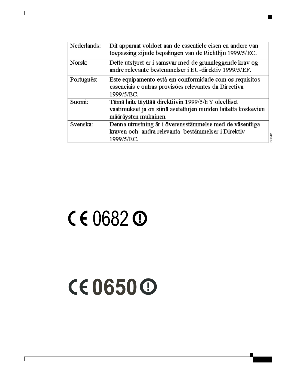
C-5
Cisco Aironet Wireless LAN Client Adapt er s Inst all ation and Configuration Guide fo r MS-DOS
OL-1744-02
AppendixC Declaratio ns of Conformit y and Regulator y Informati on
European Community, Switzerland, Norway, Icela nd, and Lie chtenstein
The Declara tion of Conformity related to this product can be found at this URL:
http:/ /w w w.ciscofax.com .
For the 34 0 s er ies, th e following st an da rd s w er e applied :
• Radio: ETS 300.328
• EMC: ETS 300.826
• Safety: EN 60950
The followin g C E ma rk i s affixed t o th e 3 4 0 s eries eq ui pm en t:
For the 35 0 s er ies, th e following st an da rd s w er e applied :
• Radio: E N 300.328-1, EN 300.328-2
• EMC: EN 301 489-1, EN 301 489-17
• Safety: EN 60950
The followin g C E mark is affixed to the 350 ser ies equipm en t ( exc ep t f o r th e mi ni - P CI ca rd ):
The a bove CE ma rk is req uired a s o f A pr il 8, 2 0 00 but mig ht chan ge in t he f uture.
49325
Page 80

C-6
Cisco Aironet Wireless LAN Client Adapters Installation and Configuration Guide for MS-DOS
OL-1744-02
Appendix C Declarations of Conformity and Regulatory Information
Declaration of Conformity for RF Exposure
The followin g C E m a rk i s affixed t o th e 3 5 0 ser ies m in i-P C I car d :
Note This equi pment is in tended to be used in all E U and EF TA countrie s. O ut do o r u s e may be restri cted
to certain frequencies or may require a license for operation. For more details, contact Cisco
Corporate Compl ian ce.
Note Combin at io ns of power leve ls and ante n na s r es u lt in g in a rad iated p ow er level of ab ove 100 m W
equivalent isotropic radiated power (EIRP) are considered as not compliant with the above mentioned
directive and are not allowed for use within the European community and countries that have adopted
the Euro pe an R &TTE direct ive 199 9/ 5/E C an d th e C EP T re co m me nd at io n Rec 70.03. F or more
details on l egal co mbination s o f p ower l evels an d an te nn as, contac t C is c o C o rp o ra te Co m p li an ce.
Declaration of Conformity for RF Ex posure
The radio module has been evaluated under FCC Bulletin OET 65C and found compliant to the
requir ement s a s s et for th in C FR 4 7 Se c tion s 2. 10 91, 2 . 109 3, a nd 15.2 47 (b) (4) add ress ing RF Ex posu re
from radio frequency devices.
Page 81
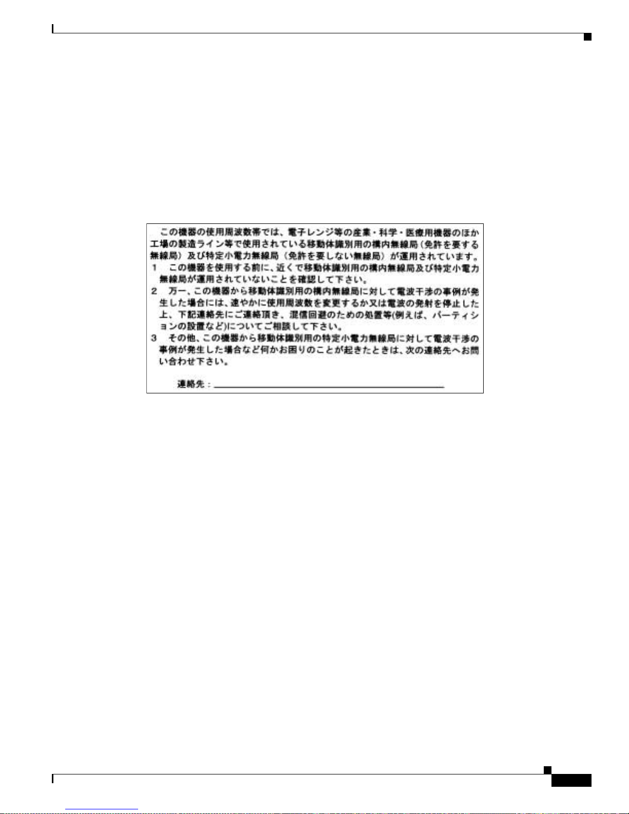
C-7
Cisco Aironet Wireless LAN Client Adapt er s Inst all ation and Configuration Guide fo r MS-DOS
OL-1744-02
AppendixC Declaratio ns of Conformit y and Regulator y Informati on
Guidelines for Operating Cisco Aironet Wireless LAN Client Adapters in Japan
Guidelines f or Operating Cisco Aironet Wireless LAN C lient
Adapters in Japan
This section provides guidelines for avoiding interfer ence when operating Cisco Airon et Wire less LAN
Client A dapter s in J a pan. Th e se gu idelin es ar e p rov i ded in bo th J apane s e and En g lish.
Japanese Tran sl at i on
English Translation
This equi pment op er ate s in th e s ame f re qu en cy bandwid th as ind u str ial, scientific, and m ed ical devices
such as microwave ove ns and mobile objec t identification (RF-ID) systems (licensed premises radio
stations and unlicensed specified low-power radio stations) used in factory production lines.
1. Bef ore us ing th is equi pmen t, make su re th at n o pr emis es radio st at ions o r spe cified low-pow er radi o
stations of RF-ID are used in the vicinity.
2. If this equipment causes RF interference to a premi ses radio station of RF-ID, promptly change the
frequency or stop using the device; call the contact number and ask for recommendations on
avoiding radio interference, such as setting partitions.
3. If this equ ip men t causes RF in ter f er en ce to a s pe cifi ed low -p ower r adio sta tio n o f RF- I D, call the
contact number.
Contact Number: 03-5219-6000
03-5219-6000
43768
Page 82

C-8
Cisco Aironet Wireless LAN Client Adapters Installation and Configuration Guide for MS-DOS
OL-1744-02
Appendix C Declarations of Conformity and Regulatory Information
Guidelines for Oper at in g Cisc o Ai ron e t Wire le ss LAN Client Adapter s in Ja pan
Page 83

D-1
Cisco Aironet Wireless LAN Client Adapters Installation and Conf iguration Guide for MS-DOS
OL-1744-02
APPENDIX
D
Translated Safety Warnings
This appendix provides translations of the safety warnings that appear in this publication. These
translated w ar ni ngs a pp ly to othe r do cu ments in w h ich t hey ap p ear i n En gl ish .
These to pics a re cove re d in th is sect ion:
• Explos ive D e vi c e P ro ximity Warning , page D -2
• Lightning Activity Warning, page D-3
• Installation Warning, page D-3
• Circuit Breaker (15A) Warning, page D-4
Page 84

D-2
Cisco Aironet Wireless LAN Client Adapters Installation and Configuration Guide for MS-DOS
OL-1744-02
Appendix D Translated Safety Warnings
Explosive Device Proximity Warn ing
Explosive Device Proximity Warning
Warning
Do not operate your wireless network device near unshielded
blasting
caps or in an explosive environment unless the devi ce
has been modified to be especially qualified for such use.
Waarschuwing
Gebruik dit draadloos netwerkapparaat alleen in de buurt van
onbeschermde ontstekers of in een omgeving met explosieven
indien het apparaat speciaal is aangepast om aan de eisen voor
een dergelijk gebruik te voldoen.
Varoitus
Älä käytä johdotonta verkkolaitetta suojaamattomien
räjäytysnallien läheisyydessä tai r äjäytysalueella, jos laitetta ei
ole erityisesti muunnettu sopivaksi sellaiseen käyttöön.oen.
Attention
Ne jamais utiliser un équipement de rés eau sans fil à proximité
d'un détonateur non blindé ou dans un li eu présentant des ri sques
d'explosion, sauf si l'équipement a été modifié à cet effet.
Warnung
Benutzen Sie Ihr drahtloses Netzwerkgerät nicht in der Nähe
ungeschützter Sprengkapseln oder anderer explosiver Stoffe, es
sei denn, Ihr Gerät wurde eigens für diesen Gebrauch modifiziert
und bestimmt.
Avvertenza
Non utilizzare la periferica di rete senza fili in prossimità di un
detonatore non protetto o di esplosivi a meno che la periferi ca
non sia stata modificata a tale proposito.
Advarsel
Ikke bruk den trådløse nett verksenheten nært i nnt il uisolerte
fenghetter eller i et eksplosivt miljø med mindre enheten er
modifisert slik at den tåler slik bruk.
Aviso
Não opere o dispositivo de rede sem fios pert o de cápsulas
explosivas não protegidas ou num ambiente explosivo, a não ser
que o dispositivo tenha sido modificado para se qualificar
especialmente para essa utilização.
¡Advertencia!
No utilizar un aparato de la red sin cable cerca de un detonador
que no esté protegido ni tampoco en un entorno explosivo a
menos que el aparato haya sido modificado con ese fin.
Varning!
Använd inte den trådlösa nätverksenheten i närheten av
oskyddade tändhattar eller i en explosiv miljö om int e enheten
modifierats för att kunna användas i sådana sammanhang.
Page 85

D-3
Cisco Aironet Wireless LAN Client Adapt er s Inst all ation and Configuration Guide fo r MS-DOS
OL-1744-02
AppendixD Translate d Safety Warnings
Lightning Activity Warning
Lightning Activity Warning
Installati on Warning
Warning
Do not work on the system or connect or disconnect cables
during periods of lightning activity.
Waarschuwing
Tijdens onweer dat gepaard gaat met bliksem, dient u niet aan
het sy steem te werken of kabels aan te sluiten of te ontkoppelen.
Varoitus
Älä työskent ele järjestelmän parissa äläkä yhdistä tai irrota
kaapeleita ukkosilmalla.
Attention
Ne pas travailler sur l e système ni brancher ou débrancher les
câbles pendant un orage.
Warnung
Arbeiten Sie nicht am System und schließen Sie keine Kabel an
bzw. trennen Sie keine ab, wenn es gewittert.
Avvertenza
Non lavorare sul sistema o collegare oppure scollegare i cavi
durante un temporale con fulmini.
Advarsel
Utfør aldri arbeid på systemet, eller koble kabler til eller fra
systemet når det tordner eller lyner.
Aviso
Não trabalhe no sistema ou l igue e des ligue cabos durante
períodos de mau tempo (trovoada).
¡Advertencia!
No operar el sistema ni conectar o desconectar cables durante
el transcurso de descargas eléctricas en la atmósfera.
Varning!
Vid åska skall du aldrig utf öra arbete på systemet eller ansluta
eller koppla loss kablar.
Warning
Read the installation instructions before you connect the sys tem
to its power source.
Waarschuwing
Raadpleeg de installatie-aanwijzingen voordat u het systeem
met de voeding verbindt.
Varoitus
Lue asennusohjeet ennen järjestelmän yhdistämistä
virta lähteeseen.
Page 86

D-4
Cisco Aironet Wireless LAN Client Adapters Installation and Configuration Guide for MS-DOS
OL-1744-02
Appendix D Translated Safety Warnings
Circui t B r eaker (15A) War ning
Circuit Breaker (15A) Warn ing
Attention
Avant de brancher le système sur la source d'alimentation,
consulter les directives d'installation.
Warnung
Lesen Sie die Installationsanweisungen, bevor Sie das System
an die Stromquelle anschließen.
Avvertenza
Consultare le istruzioni di installazione prima di collegare il
sistema all’alimentatore.
Advarsel
Les installasjonsinstruksjonene før systemet kobles til
strømkilden.
Aviso
Leia as instruções de instalação antes de ligar o sistema à sua
fonte de energia.
¡Advertencia!
Ver l as instrucciones de instalación antes de con ectar el sistema
a la red de alimentación.
Varning!
Läs installationsanvisningarna innan du kopplar systemet till
dess strömförsörjningsenhet.
Warning
This product relies on the building’s installation for short-circuit
(overcurrent) protection. Ensure that a fuse or circuit breaker no
larger than 120 VAC, 15A U.S. (240 VAC, 10A international) is used
on the phase conductors (all current-carrying conductors).
Waarschuwing
Dit produkt is afhankelijk van de installatie van het gebouw voor
kortsluit- (overstroom)beveiliging. Controleer of er een zekering
of stroomverbreker van niet meer dan 120 V olt wisselstroom, 1 5 A
voor de V.S. (240 Volt wisselstroom, 10 A internationaal) gebruikt
wordt op de fasegeleiders (alle geleiders die stroom voeren).
Varoitus
Tämä tuote on riippuvainen rakennukseen asennetusta
oikosulkusuojauksesta (ylivirtasuojauksesta). Varmista, että
vaihevirtajohtimissa (kaikissa virroitetuissa johtimissa)
käytetään Yhdy svalloissa alle 120 voltin, 15 ampeerin ja monissa
muissa maissa 240 voltin, 1 0 ampeerin sulaketta tai
suojakytkintä.
Attention
Pour ce qui est de la protection contre les courts-circuits
(surtension), ce produit dépend de l'installation électrique du
local. Vérifier qu'un fusible ou qu'un disjoncteur de 120 V alt.,
15 A U.S. maximum (240V alt., 10A international) est utilisé sur
les conducteurs de phase (conducteurs de charge).
Page 87

D-5
Cisco Aironet Wireless LAN Client Adapt er s Inst all ation and Configuration Guide fo r MS-DOS
OL-1744-02
AppendixD Translate d Safety Warnings
Circuit Breaker (15A) Warning
Warnung
Dieses Produkt ist darauf angewiesen, daß im Gebäude ein
Kurzschluß- bzw. Überstromschutz installiert ist. Stellen Sie
sicher , daß eine Sicherung oder ein Unterbrecher von nicht mehr
als 240 V Wechselstrom, 10 A (bzw. in den USA 1 20 V
Wechselstrom, 15A) an den Phasenleitern (allen stromführenden
Leitern) verwendet wird.
Avvertenza
Questo prodotto dipende dall’installazione dell’edificio per
quanto riguarda la protezione contro cortocircuiti
(sovracorrente). Verificare che un fusibile o interruttore
automatico, non superiore a 120 VCA, 15 A U.S. ( 2 40 VCA, 10 A
internazionale) sia stato usato nei fili di fase (t utti i condutt ori
portatori di corrente).
Advarsel
Dette produktet er avhengig av bygningens installasjoner av
kortslutningsbeskyttelse (overstrøm). Kontroller at det brukes en
sikring eller strømbryter som ikke er større enn 120 VAC, 15 A
(USA) (2 40 VAC, 10 A int er nas jo nal t ) på faselederne (alle
strømf ørende ledere).
Aviso
Este produto depende das instalações existentes para protecção
contra curto-circuito (sobrecarga). Assegure-se de que um
fusível ou disjuntor não superior a 240 VAC, 10A é utilizado nos
condutores de fase (todos os condutores de transporte de
corrente).
¡Advertencia!
Este equipo utiliza el sistema de protección contra cortocircuitos
(o sobrecorrientes) deló propio edificio. Asegurarse de que se
utiliza un fusible o interruptor automático de no más de
240 voltios en corriente alterna (VAC), 10 amperios del estándar
internacional (120 VAC, 15 amperios del estándar USA) en los
hilos de fase (todos aquéllos portadores de corriente).
Varning!
Denna produkt är beroende av i byggnaden installerat
kortslutningsskydd (överstr ömsskydd). Kontrollera att säkring
eller överspänningsskydd används på fasledarna (samtliga
strömf örande ledare) för internationellt bruk max. 240 V
växelström, 10 A (i USA max. 120 V växelström, 15 A).
Page 88

D-6
Cisco Aironet Wireless LAN Client Adapters Installation and Configuration Guide for MS-DOS
OL-1744-02
Appendix D Translated Safety Warnings
Circui t B r eaker (15A) War ning
Page 89

IN-1
Cisco Aironet Wireless LAN Client Adapt er s Inst all ation and Configuration Guide fo r MS-DO S
OL-1744-02
INDEX
A
ad hoc variab les 3-16
antenna
attach in g
2-4
detachin g 2-5
gains B-3 to B-4
antennas
safety g ui de lines for
2-2
specif ica ti on s A-4
used wit h cl ien t ad ap ter s 1-4
audience vi
AWCALLID.EXE 4-7, 4-8
AWCLEAP.EXE 4-6
B
basic system parameters 3-7
C
Canadian co mp liance stat em e nt C-3
channels B- 2
configuration utilitie s 4-3
coverage optio ns 1-9
heavy overlap 1-9
minimal overlap 1-9
multiple overlapping systems 1-10
D
data rates A-3
data transpa renc y and proto cols 1-5
protocols supported 1-5
diagnostic utilities 4-4
dipole antenna 1-4
diversity antenna 1-4
documentation
feedback
viii
obtain ing vii
ordering viii
documentation CD-ROM vii
DOS utilitie s 4-3
AWCALLID.EXE 4-7, 4-8
AWCLEAP.EXE 4-6
gettin g help in 4-5
layout and format 4-4
PCMCIA.COM 4-10
RADINFO.EXE 4-11
running 4-5
WEPDOS.EXE 4-9
driver
keywo rds a nd se ttin gs
3-6
overv ie w of 3-2
E
EIRP, maximum B-3 to B-4
F
FCC
declarati on o f co nfo r m it y s tat ement
C-2
firmware
loading new versions
4-3
fragmentation variable s 3-9
Page 90

Index
IN-2
Cisco Aironet Wireless LAN Client Adapters Installation and Configuration Guide for MS-DOS
OL-1744-02
frequencies B-2
I
infras tr uc tu re param eters 3-13
installing har dware 2-1 to 2-8
installing so f tw ar e 3-1 to 3-17
adapter keywords 3-16
additional requirements and features 3-5
ad hoc variables 3-16
basic system parameters 3-7
driver keywords and settings 3-6
fragmentation variable s 3-9
infrastructure paramete rs 3-13
network performance variables 3-8
power management variables 3-10
scan ni ng var iables 3-12
K
keywo rds
adapter
3-16
L
LEDs 1-4
interpreting 5-2
link t es t 1-5, 4-2
using Windows 3.xx or MS-DOS to perform 4-2
LM card c lien t ad ap t er
antenna
1-4
N
NDIS2 driver
MS-D O S in s ta llation
3-3
Windows for Workgroups installation 3-3
network performance variables 3-8
O
ODI driver
installation
3-5
overview 1-1 t o 1-10
P
package contents 2-3
packet driver
MS-DOS installation
3-4
PC card client adap t er
antenna
1-4
removing 2-7
PCMCIA.COM 4-10
power level
maximum
B-3 to B-4
power management variables 3-10
R
RADINFO.EXE 4-11
radio
complia nc e s p ec if ications
A-5
descr iption 1-3
regulatory information C-1 to C-7
specifications A-2 to A-4
regulatory
domains
B-2
relate d pub lic atio ns vii
RF exposure declaration of conformity state ment C-6
S
safety in f or m a tion
FCC safe ty co m p li an ce s tatem e nt
2-2
guide lin es 2-2
specifications A-5
Page 91

Index
IN-3
Cisco Aironet Wireless LAN Client Adapt er s Inst all ation and Configuration Guide fo r MS-DO S
OL-1744-02
warnings 2-2
safety warnings, translated D- 1 to D-5
scanning variables 3-12
security featu res 1-6
sensit iv ity A-3
site survey 4-2
specifications A-2 to A-5
spread spectrum 1-3
system configurations 1-6
ad hod wireless LAN 1-6
extended infrastructure using repeaters 1-8
wireles s infr astr uctu re 1-7
wireles s infr astr uctu re wit h wor kstat ions acc ess ing
wired LAN
1-7
T
technical ass i stan ce
contacting TAC
ix
obtaining viii
Technical Assistance Center (TAC) ix
technical s p eci ficat io ns A- 2 to A-5
throughput 3-10
troubleshooting information
location on Cisco.com
5-2
U
unpackin g th e cli en t adapter 2-3
utiliti es 4-1 to 4-11
site survey and link test 4-2
W
warnings 2-2
WEPDOS.EXE 4-9
wireless LAN adapter
antenna connectors
2-4
inserting into computing device 2-5 to 2-7
introduction to 1-2
link t es t 1-5
parts o f 1-3
radio ranges 1-4
removing from co m puting devi ce 2-7 to 2-8
security featu res 1-6
termi n ology used 1-3
unpackin g 2-3
workstations
defined
1-3
World Wide Web vii
Cisco.co m viii
Page 92

Index
IN-4
Cisco Aironet Wireless LAN Client Adapters Installation and Configuration Guide for MS-DOS
OL-1744-02
 Loading...