

Page 1

Preface
Cisco Aironet Power Injector
(AIR-PWRINJ5) Installation Guide
The Cisco Aironet Power Injector (AIR-PWRINJ5) increases wireless LAN deployment flexibility of
Cisco Aironet Access Points by providing an alternative powering option to local power, inline
power-capable multiport switches, and multiport power patch panels.
The single-port Cisco Aironet Power Injector provides 802.3af power and data signal, sending both to
the Cisco Aironet Access Point.
The power injectors provide up to 15.4 W over the unused wire pairs of a Category 5 or better Ethernet
cable, supplying enough power for a distance of 328 ft. (100 m) on the Cisco Aironet 1040, 1140, 1260,
2600, and 3500 Series Access Points. While it can also support the Cisco Aironet Series 3600 Access
Points when modules are not being used, it is recommended to use the AIR-PWRINJ4= power injector
instead for the 3600 series, as it has sufficient power to supply to the AP and any installed modules.
This guide covers the following Cisco Aironet Power Injector:
• Cisco Aironet Power Injector (AIR-PWRINJ5)
Cisco Aironet Power Injector
The Cisco Aironet Power Injector provides both power and data to a connected Cisco Aironet Access
Point. The device serves the following functions:
• It provides Category 5 or better Ethernet media to the access point.
• It uses wires in an Ethernet cable to supply inline 15.4 W power to an access point. The power
injector provides an easy and economical way to provide data and power to an access point located
in areas where power is not available.
The power injector is used with the following Cisco Aironet Series Access Points:
• 1040 series access points
• 1140 series access points
• 1260 series access points
Cisco Systems, Inc.
www.cisco.com
Page 2
Cisco Aironet Power Injector
• 1600 series access points
• 2600 series access points
• 3500 series access points
A Category 5 or better Ethernet cable connects the injector to a 10/100/1000 Ethernet switch, hub, or
etwork, and another cable carries power and data to the access point's WAN Ethernet port. The power
n
injector’s built-in power supply has a C14 connector that connects to a wall outlet or power strip. The
power injector connects to a wall outlet or power strip.
Caution To avoid overheating and possible failure, do not stack or tie together (bundle) the power injector and its
AC power cable.
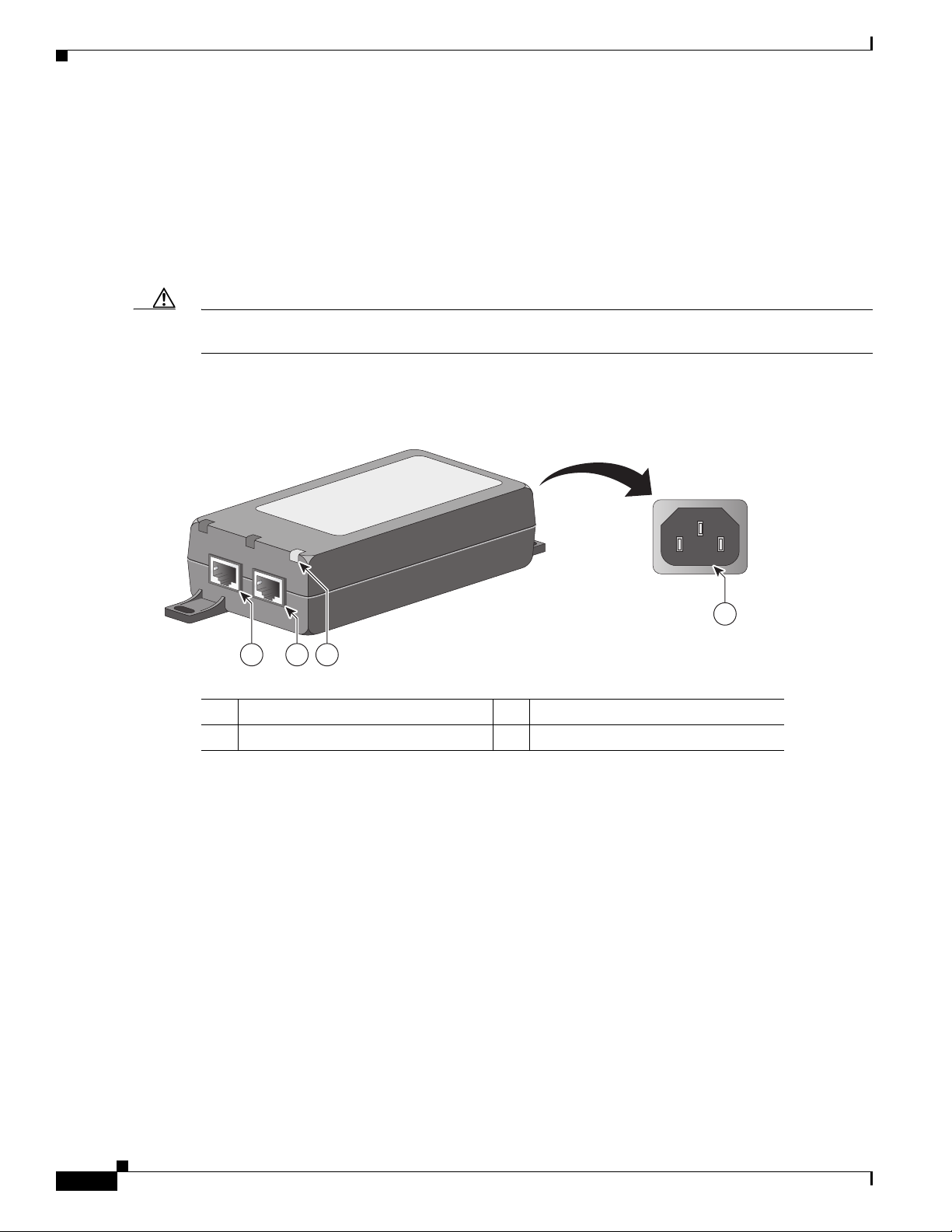
Figure 1 shows the key features of the power injector.
Figure 1 Cisco Aironet Power Injector (AIR-PWRINJ5) Features
STATUS
AP
SWITCH
346663
1 243
1 Status LED 3 AP Connector Port
2 Switch Connector Port 4 C14 Power Connector
The Status LED indicates the following system status events:
• AC Power - The LED blinks green at approximately 1.5 times per second to indicate that the Power
Injector is powered ON and ready for connection.
• AP Power - The LED lights solid green to indicate that a valid IEEE 802.3af load (AP) is detected
and powered ON.
• Invalid load connected or Fault: The LED rapidly blinks green at 10 times per second to an invalid
load connected or a Fault. In these conditions the AP has not been powered on. This occurs for 2
seconds for normal error delay, and the detection process will automatically start again after 2.2
seconds unless there is a “restart after disconnect condition” set during the initial configuration.
Cisco Aironet Power Injector (AIR-PWRINJ5) Installation Guide
2
Page 3

Network source
Figure 2 shows a typical installation scenario.
Figure 2 Power Injector AIR-PWRINJ5 Installation Scenario
SYST
1
RPS
2
3
4
5
UTILSTAT
DUPLX
6
SPEED
7
8
10Base-T / 100Base-TX
9
MODE
10
11
12
13
14
15
16
17
18
Catalyst 2950
19
SERIES
20
21
22
100Base-FX
23
24
23
24
Installing the Power Injector
Power injector
Power
cord
Access point
Unpacking the Power Injector
The typical power injector package contains the following items:
• Power injector
• Power cord
• URL Pointer Card and China RoHS Statement
If any item is missing or damaged, contact y
Additional Requirements
Use the power cord that shipped with your power injector to supply power for the injector. If you install
the access point in an environmental air space such as above a suspended ceiling, check national and
local safety codes to make sure that the Ethernet cable you connect to the unit meets applicable
standards.
Note The AIR-PWRINJ5 is not plenum and should not be installed in the plenum airspace.
346602
our Cisco representative or reseller.
Note The maximum distance that is supported for in-line power is 328 ft. (100 m), including the length of the
6.5-ft. (2-m) Ethernet cable provided with the power injector.
Installing the Power Injector
Follow these steps to install the power injector:
1. Plug a Category-5 Ethernet cable into the port on the power injector labeled AP.
Cisco Aironet Power Injector (AIR-PWRINJ5) Installation Guide
3
Page 4

Installing the Power Injector
2. Plug the other end of the Ethernet cable into the WAN uplink Ethernet port of the access point.
3. Plug a Category-5 Ethernet cable into the port on the power injector labeled Switch.
4. Plug the other end of the Ethernet cable into your 10/100/1000 Ethernet switch, hub, or network.
5. When power is applied, the Status LED blinks green at approximately 1.5 times per second. When
the AP is detected, the Status LED glows solid green. If the power injector is connected incorrectly,
the Status LED blinks green at 10 times per second.
6. Secure the power injector by mounting it to a vertical or horizontal surface using the mounting
keyholes on the bottom of the unit.
Mounting Instructions
You can mount the power injector to most vertical or horizontal surfaces using the mounting tabs on the
top right and bottom left of the unit.
Using the Mounting Tabs
To mount the power injector to a vertical or horizontal surface using the mounting tabs, you will need
the following parts and tools:
• Two #6 plastic wall anchors if mounting to a drywall surface
• Two #6 x 1-in. (2.5 cm) sheet-metal screws
• A drill and a 3/16-in (0.48-cm) drill bit
• A Phillips head screw driver
• A small hammer
Follow these steps to mount the power injector:
1. Using the holes in the power injector mounting tabs as a template, mark the locations on the surface
where you will drill the holes for the wall anchors or screws.
2. Drill a 3/16-in. (4.7-mm) hole at each marked location.
3. If you are using #6 wall anchors, use a hammer to install them in the holes.
4. Hold the power injector to the wall and align the mounting tabs on the power injector with the screw
holes.
5. Insert the #6 screws through the mounting tabs and into the holes in the wall or surface.
6. Use a Phillips head screwdriver to drive the screws into the surface.
Note If the power injector is not securely fastened, continue making small adjustments until you are
satisfied.
Cisco Aironet Power Injector (AIR-PWRINJ5) Installation Guide
4
Page 5

Specifications
This table lists specifications for the power injectors:
Specification AIR-PWRINJ5=
Electrical 802.3af compliant 15.4 W power
Connectors 2 RJ-45 10/100/1000 (Cat 5 or better Ethernet cable)
Dimensions (L, W, H) 165 mm x 65 mm x 36 mm (6.5 in x 2.6 in x 1.4 in)
Stacking restrictions
Mechanicals
Do not stack. Do not bundle the power injector and AC
wer cable.
po
Specifications
Regulatory Information
The following information is for FCC compliance of Class B devices:
The equipment described in this manual generates and m
installed in accordance with Cisco’s installation instructions, it may cause interference with radio and
television reception. This equipment has been tested and found to comply with the limits for a Class B
digital device in accordance with the specifications in part 15 of the FCC rules. These specifications are
designed to provide reasonable protection against such interference in a residential installation.
However, there is no guarantee that interference will not occur in a particular installation.
Modifying the equipment without Cisco’s written author
complying with FCC requirements for Class A or Class B digital devices. In that event, your right to use
the equipment may be limited by FCC regulations, and you may be required to correct any interference
to radio or television communications at your own expense.
You can determine whether your equip
stops, it was probably caused by the Cisco equipment or one of its peripheral devices. If the equipment
causes interference to radio or television reception, try to correct the interference by using one or more
of the following measures:
ay radiate radio-frequency energy. If it is not
ization may result in the equipment no longer
ment is causing interference by turning it off. If the interference
Cisco Aironet Power Injector (AIR-PWRINJ5) Installation Guide
5
Page 6

Regulatory Information
• Turn the television or radio antenna until the interference stops.
• Move the equipment to one side or the other of the television or radio.
• Move the equipment farther away from the television or radio.
• Plug the equipment into an outlet that is on a different circuit from the television or radio. (That is,
make certain the equipment and the television or radio are on circuits controlled by different circuit
breakers or fuses.)
Modifications to this product not authorized by Cisco Systems, Inc. could void the FCC approval and
negate your authority to operate the product.
Applicable Standards
Except where indicated, the Cisco Aironet Power Injector (AIR-PWRINJ5) meets the following
standards:
• FCC Part 15.107 and 15.109 Class B
• ICES-003 Class B (Canada)
• AS/NZS 3548 Class B
• VCCI Class B
• EN 301.489-1 and 17
• EN 55022
• EN 55024
• EN 60950
• UL 60950
• CSA C22.2 No. 60950
• IEC 60950
Cisco Aironet Power Injector (AIR-PWRINJ5) Installation Guide
6
 Loading...