

Page 1

Cisco Aironet 1520 Series Outdoor Mesh Access Point Hardware Installation Guide
May, 2008
Revised June, 2011
Americas Headquarters
Cisco Systems, Inc.
170 West Tasman Drive
San Jose, CA 95134-1706
USA
http://www.cisco.com
Tel: 408 526-4000
800 553-NETS (6387)
Fax: 408 527-0883
Text Part Number: OL-12632-03
Page 2

THE SPECIFICATIONS AND INFORMATION REGARDING THE PRODUCTS IN THIS M ANUAL ARE SUBJECT TO CHA NGE WITHOUT NO TICE. ALL
STATEMENTS, INFORMATION, AND RECOMMENDATIONS IN THIS MANUAL ARE BELIEVED TO BE ACCURATE BUT ARE PRESENTED WITHOUT
WARRANTY OF ANY KIND, EXPRESS OR IMPLIED. USERS MUST TAKE FULL RESPONSI BILITY FOR THEIR APPLICA TION OF ANY PRODUCT S.
THE SOFTWARE LICENSE AND LIMITED WARRANTY FOR THE ACCOMPANYING PRODUCT ARE SET FORT H IN THE INFORMATION PACKET T HAT
SHIPPED WITH THE PRODUCT AND ARE INCORPORATED HEREIN BY THIS REFERENCE. IF YOU ARE UNABLE TO LOCATE THE SOFTWARE LICENSE
OR LIMITED WARRANTY, CONTACT YOUR CISCO REPRESENTATIVE FOR A COPY.
The following information is for FCC compliance of Class A devices: This equipment has been tested and found to comply with the limits for a Class A digital device, pursuant
to part 15 of the FCC rules. These limits are designed to provide reasonable protection against harmful interference when the equipment is operated in a commercial
environment. This equipment generates, uses, and can radiate radio-frequency energy and, if not installed and used in accordance with the instruction manual, may cause
harmful interference to radio communications. Operation of this equipment in a residential area is likely to cause harmful interference, in which case users will be required
to correct the interference at their own expense.
The following information is for FCC compliance of Class B devices: The equipment described in this manual generates and may radiate radio-frequency ener gy. If it is not
installed in accordance with Cisco’s installation instructions, it may cause interference with radio and television reception. This equipment has been tested and found to
comply with the limits for a Class B digital device in accordance with the specifications in part 15 of the FCC rules. These specifications are designed to provide reasonable
protection against such interference in a residential installation. However, there is no guarantee that interference will not occur in a particular installation.
Modifying the equipment without Cisc o’s writ ten author ization m ay resul t in the equi pment no lo nger comp lyi ng with FCC requi rements for Class A or Class B digital
devices. In that event, your right to use the equ ipment may be limit ed by FCC regul ations , and you may be requir ed to correct a ny interference to radio or television
communications at your own expense.
You can determine whether your equipment is causing interference by turning it off. If the interferen ce stops, it was probably caused by the Cis co equipm ent or one of its
peripheral devices. If the equipment causes interference to radio or television reception, try to correct the interference by using one or more of the following measures:
• Turn the television or radio antenna unt il the int erference st ops.
• Move the equipment to one side or the other of the televisio n or radi o.
• Move the equipment farther away from the te levision or radio.
• Plug the equipment into an outlet that is on a di fferent cir cuit from the televi sion o r radio. (That is, make certain th e equipment and the te levision or radio are on circuit s
controlled by different circuit breaker s or fuses.)
Modifications to this product no t author ized by Cis co Syst ems, Inc. coul d voi d the FCC appro val and ne gate your authorit y to op erate the pr oduct.
The Cisco implementation of TCP head er compressi on is an adap tation of a program developed by the Universi ty of Ca lifornia, Berk eley (UCB) as part of UCB ’s public
domain version of the UNIX operatin g system. All rights reserved . Copyri ght © 1981 , Rege nts of the Uni versity of Calif ornia.
NOTWITHSTANDING ANY OTHER WARRANTY HEREIN, ALL DOCUMENT FILES AND SOFTWARE OF THE SE SUPPLIERS ARE PROVIDED “AS IS” WITH
ALL FAULTS. CISCO AND THE ABOVE-NAMED SUPPLIERS DISCLAI M ALL WARRANTIE S, EXPRESSED OR
LIMITATION, THOSE OF MERCHANTABILITY, FITNESS FOR A PARTICULAR PURPOSE AND NO NINFRINGEM ENT OR ARISING FROM A COURS E OF
DEALING, USAGE, OR TRADE PRACTICE.
IN NO EVENT SHALL CISCO OR ITS SUPPLIERS BE LIABLE FOR ANY INDIRECT, SPECIAL, CONSEQUENTIAL, OR INCIDENTAL DAMAGES, INCLUDING ,
WITHOUT LIMITATION, LOST PROFITS OR LOSS OR DAMAGE TO DATA ARISING OUT OF THE USE OR INABILITY TO USE THIS MANUAL, EVEN IF CISCO
OR ITS SUPPLIERS HAVE BEEN ADVISED OF THE POSSIBILITY OF SUCH DAMAGE S.
Cisco and the Cisco Logo are trademarks of Cisco Systems, Inc. and/or its affiliates in the U.S. and other coun tries. A listing of Cisco's trademarks can be foun d at
www.cisco.com/go/trademarks. Third party trademarks mentioned are the pro perty of their respective owners. The use of the word partner does not imply a partnersh ip
relationship between Cisco and any other comp any. (1 005R)
Any Internet Protocol (IP) addresses used in this document are not intended to be actual addresses. Any examples, command display output, and figures included in the
document are shown for illustrative pur poses onl y. Any use of act ual IP addr ess es in ill ustr ativ e conten t is uninten tio nal and coincident al.
Cisco Aironet 1520 Series Outood Mesh Acces Point Hardware Installation Guide
© 2011 Cisco Systems, Inc. All rights res erved.
IMPLIED, INCLUDING, WI TH OUT
Page 3

CONTENTS
Preface VII
Objectives I-VII
Audience I-VII
Organization I-VII
Conventions I-VIII
Related Publications I-XIII
Finding the Product Serial Number I-XIV
Obtaining Documentation, Obtaining Support, and Security Guidelines I-XIV
CHAPTER
1 Overview 1-1
Hardware Features 1-2
Connectors 1-6
Multiple Radio Operation 1-7
External Antennas 1-7
Multiple Power Sources 1-8
Ethernet Ports 1-9
Cable Modem 1-10
Metal Enclosure 1-10
Optional Hardware 1-10
Network Deployment Examples 1-11
Wireless Backhaul 1-12
Point-to-Point Bridging 1-12
Point-to-Multipoint Bridging 1-13
Mesh Network 1-13
Layer 3 Network Operation 1-15
Antenna Connector Locations 1-6
CHAPTER
OL-12632-03
2 Mounting Instructions 2-1
Unpacking the Access Point 2-2
Package Contents 2-2
Tools and Materials That You Supply 2-2
Pole Installation 2-3
Cable Strand Installation 2-3
Warnings 2-4
Cisco Aironet 1520 Series Outdoor Mesh Access Point Hardware Installation Guide
III
Page 4

Contents
Safety Information 2-4
FCC Safety Compliance Statement 2-4
Safety Precautions 2-5
Avoiding Damage to Radios in a Testing Environment 2-7
Installation Guidelines 2-8
Site Surveys 2-8
Before Beginning the Installation 2-9
Becoming Familiar with Access Point Installation Components 2-9
Antenna Connector Locations 2-13
Adding the Access Point MAC Addresses to the Controller Filter List 2-14
Configuring a RAP 2-15
Configuring a Bridge Group Name 2-15
Mounting the Access Point 2-16
Installation Options 2-16
Access Point Mounting Orientation 2-17
Mounting the Access Point on a Wall 2-17
Mounting the Access Point on a Pole 2-21
Assembling the Pole Clamp Bracket and the Mounting Bracket 2-21
Pole Mounting 2-24
Cable Strand Mounting 2-30
Opening the Access Point Hinged Cover 2-38
Closing the Access Point Hinged Cover 2-39
Using the Reset Button 2-40
Reboot the Access Point 2-41
Disabling Backup Battery Power 2-42
IV
Grounding the Access Point 2-42
Connecting a Fiber-Optic Cable to the Access Point 2-43
Powering the Access Point 2-46
Connecting a 1520 Series Power Injector 2-46
Connecting an Ethernet Cable to the Access Point 2-47
Connecting Streetlight AC Power 2-50
Connecting an AC Power Cable to the Access Point 2-52
Connecting a DC Power Cable to the Access Point 2-53
Connecting a Cable POC Power to the Access Point 2-57
Installing the Access Point in Hazardous Locations 2-60
Required Tools and Materials 2-60
Warnings 2-61
Compliance 2-61
Compliance Label 2-61
Cisco Aironet 1520 Series Outdoor Mesh Access Point Hardware Installation Guide
OL-12632-03
Page 5

Mounting the Access Point 2-64
Routing and Connecting Ground, AC Power, and Ethernet Backhaul Cables 2-64
Installing the PG-13 1/2 NPT Conduit Adapters 2-65
Opening the Access Point Hinged Cover 2-66
Connecting Ground and AC Power 2-67
Closing the Access Point Hinged Cover 2-68
Connecting the Ethernet Backhaul Cable 2-69
Performing Maintenance 2-69
Removing the Access Point from Service 2-70
Conducting Periodic Inspections 2-70
What to Do Next 2-71
Contents
CHAPTER
3 Troubleshooting 3-1
Guidelines for Using the Access Points 3-2
Important Notes 3-2
Convergence Delays 3-2
Bridge Loop 3-3
Controller DHCP Server 3-3
MAP Data Traffic 3-3
Controller MAC Filter List 3-3
Using DHCP Option 43 3-4
Monitoring the Access Point LEDs 3-4
Verifying Controller Association 3-5
Changing the Bridge Group Name 3-6
Cable Modem LEDs 3-7
Connecting to the Access Point Locally 3-8
Access Point Power Injector 3-9
Monitoring the Power Injector LEDs 3-10
CHAPTER
OL-12632-03
4 Installing or Replacing the Backup Battery 4-1
Before Beginning the Installation or Replacement 4-2
Opening the Access Point Radio Cover 4-3
Removing a Backup Battery 4-4
Installing a New Backup Battery 4-5
Connecting the Backup Battery Cable and Closing the Radio Cover 4-6
What to do Next 4-6
Cisco Aironet 1520 Series Outdoor Mesh Access Point Hardware Installation Guide
V
Page 6

Contents
APPENDIX
APPENDIX
A Translated Safety Warnings A-1
B Declarations of Conformity and Regulatory Information B-1
Manufacturers Federal Communication Commission Declaration of Conformity Statement B-2
Industry Canada B-3
Canadian Compliance Statement B-3
Declaration of Conformity for RF Exposure B-4
European Community, Switzerland, Norway, Iceland, and Liechtenstein B-4
Declaration of Conformity with Regard to the 1999/5/EC (R&TTE Directive) B-5
Declaration of Conformity for RF Exposure B-7
Guidelines for Operating Cisco Aironet Access Points in Japan B-8
Japanese Translation B-8
English Translation B-8
VCCI Statement for Japan B-9
Administrative Rules for Cisco Aironet Access Points in Taiwan B-9
Chinese Translation B-9
English Translation B-10
APPENDIX
APPENDIX
APPENDIX
APPENDIX
Operation of Cisco Aironet Access Points in Brazil B-10
Access Point Models B-10
Regulatory Information B-10
Portuguese Translation B-11
English Translation B-11
Declaration of Conformity Statements B-11
Declaration of Conformity Statements for European Union Countries B-11
C Access Point Specifications C-1
D Channels and Power Levels D-1
E Access Point Pinouts E-1
F Configuring DHCP Option 43 F-1
Overview F-2
Configuring Option 43 for 1000 and 1500 Series Access Points F-3
Configuring Option 43 for 1100, 1130, 1200, 1240, 1250, 1300, and 1520 Series Access Points F-4
I
NDEX
VI
Cisco Aironet 1520 Series Outdoor Mesh Access Point Hardware Installation Guide
OL-12632-03
Page 7

Objectives
Preface
This section describes the objectives, audience, organization, and conventions of the Cisco Aironet 1520
Series Outdoor Mesh Access Point Hardware Installation Guide.
This publication explains the steps for installin g the Cisco Airo net 1520 Ser ies Outdoor Mesh Access
Point (hereafter called the access point). The access point is available in two models: The LAP1522 and
LAP1524.
The LAP1522 model is a dua l-radio pl atfor m that supp orts dual-b and (2. 4- and 5-G Hz) ope ration.
The LAP1524 model is a multi-radio platform that supports 3 or 4 radios (2.4-GHz, 5-GHz, and 4.9-GHz
public safety band) opera tion.
Audience
This publication is for the person installing and configuring an access point for the first time. The
installer should be familiar with network structures, terms, and concepts.
Warning
Only trained and qualified personnel should be allowed to install, replace, or service this equipment.
Statement 1030
Organization
This guide contains the following secti ons:
Chapter 1, “Overview,” describes the majo r c om pon ents and fe atur e s of the ac cess poi nt.
Chapter 2, “Mounting Inst ructions,” provides warnings, safety information, and mounting information
you need to install your access point . The ch apte r cont ain s a new section that provides in for mat ion and
procedures for mounting the access point in Class I, Division 2, Zone 2 hazar dous locatio ns.
OL-12632-03
Chapter 3, “Troubleshooting,” provides basic troublesho oting pr ocedu re s f or t he a ccess p oi nt.
Chapter 4, “Installing or Rep laci ng the Backup Battery,” describes the pr ocedure s to instal l or replace
the backup battery in t he a ccess poi nt.
Cisco Aironet 1520 Series Outdoor Mesh Access Point Hardware Installation Guide
VII
Page 8

Conventions
Appendix A, “Translated Safety Warnings,” indicates how to access the document that provides
translations of the safety warnings that appear in this publication.
Appendix B, “D ecl ara tio ns o f Conf or mity and Regula tory Informatio n,” describes the regulatory
conventions to which the access point conform s and provides guidel ines for ope rating a ccess point s in
Japan.
Appendix C, “Access Point Specifications,” lists technical specifications for the access point.
Appendix D, “ Channe ls and Power Levels,” indicates how to access the document that lists the access
point radio channel s and the maxim um power levels supported by the world’s regulatory domains.
Appendix E, “Access Point Pinouts,” describes the conne ctor pinou ts for the access point.
Appendix F, “Configuring DHCP Option 43,” describes the procedure to configure DHC P Option 43 .
Conventions
This publication uses the following conventions to convey instructions and informa tion:
• Commands and keywords are in boldface type.
Preface
Note Means reader take note. Notes contain help ful sugg est ion s or ref ere nces to m ateri als no t cont aine d in
Caution Means read er be ca reful. In this situation, you might do something that could result in equipment
Warning
Waarschuwing
this manual.
damage or loss of data.
IMPORTANT SAFETY INSTRUCTIONS
This warning symbol means danger. You are in a situation that could cause bodily injury. Before you
work on any equipment, be aware of the hazards involved with electrical circuitry and be familiar
with standard practices for preventing accidents. Use the statement number provided at the end of
each warning to locate its translation in the translated safety warnings that accompanied this
device.
SAVE THESE INSTRUCTIONS
BELANGRIJKE VEILIGHEIDSINSTRUCTIES
Dit waarschuwingssymbool betekent gevaar. U verkeert in een situatie die lichamelijk letsel kan
veroorzaken. Voordat u aan enige apparatuur gaat werken, dient u zich bewust te zijn van de bij
elektrische schakelingen betrokken risico's en dient u op de hoogte te zijn van de standaard
praktijken om ongelukken te voorkomen. Gebruik het nummer van de verklaring onderaan de
waarschuwing als u een vertaling van de waarschuwing die bij het apparaat wordt geleverd, wilt
raadplegen.
Statement 1071
VIII
BEWAAR DEZE INSTRUCTIES
Cisco Aironet 1520 Series Outdoor Mesh Access Point Hardware Installation Guide
OL-12632-03
Page 9

Preface
Conventions
Varoitus
Attention
Warnung
TÄRKEITÄ TURVALLISUUSOHJEITA
Tämä varoitusmerkki merkitsee vaaraa. Tilanne voi aiheuttaa ruumiillisia vammoja. Ennen kuin
käsittelet laitteistoa, huomioi sähköpiirien käsittelemiseen liittyvät riskit ja tutustu
onnettomuuksien yleisiin ehkäisytapoihin. Turvallisuusvaroitusten käännökset löytyvät laitteen
mukana toimitettujen käännettyjen turvallisuusvaroitusten joukosta varoitusten lopussa näkyvien
lausuntonumeroiden avulla.
SÄILYTÄ NÄMÄ OHJEET
IMPORTANTES INFORMATIONS DE SÉCURITÉ
Ce symbole d'avertissement indique un danger. Vous vous trouvez dans une situation pouvant
entraîner des blessures ou des dommages corporels. Avant de travailler sur un équipement, soyez
conscient des dangers liés aux circuits électriques et familiarisez-vous avec les procédures
couramment utilisées pour éviter les accidents. Pour prendre connaissance des traductions des
avertissements figurant dans les consignes de sécurité traduites qui accompagnent cet appareil,
référez-vous au numéro de l'instruction situé à la fin de chaque avertissement.
CONSERVEZ CES INFORMATIONS
WICHTIGE SICHERHEITSHINWEISE
Dieses Warnsymbol bedeutet Gefahr. Sie befinden sich in einer Situation, die zu Verletzungen führen
kann. Machen Sie sich vor der Arbeit mit Geräten mit den Gefahren elektrischer Schaltungen und
den üblichen Verfahren zur Vorbeugung vor Unfällen vertraut. Suchen Sie mit der am Ende jeder
Warnung angegebenen Anweisungsnummer nach der jeweiligen Übersetzung in den übersetzten
Sicherheitshinweisen, die zusammen mit diesem Gerät ausgeliefert wurden.
Avvertenza
Advarsel
BEWAHREN SIE DIESE HINWEISE GUT AUF.
IMPORTANTI ISTRUZIONI SULLA SICUREZZA
Questo simbolo di avvertenza indica un pericolo. La situazione potrebbe causare infortuni alle
persone. Prima di intervenire su qualsiasi apparecchiatura, occorre essere al corrente dei pericoli
relativi ai circuiti elettrici e conoscere le procedure standard per la prevenzione di incidenti.
Utilizzare il numero di istruzione presente alla fine di ciascuna avvertenza per individuare le
traduzioni delle avvertenze riportate in questo documento.
CONSERVARE QUESTE ISTRUZIONI
VIKTIGE SIKKERHETSINSTRUKSJONER
Dette advarselssymbolet betyr fare. Du er i en situasjon som kan føre til skade på person. Før du
begynner å arbeide med noe av utstyret, må du være oppmerksom på farene forbundet med
elektriske kretser, og kjenne til standardprosedyrer for å forhindre ulykker. Bruk nummeret i slutten
av hver advarsel for å finne oversettelsen i de oversatte sikkerhetsadvarslene som fulgte med denne
enheten.
TA VARE PÅ DISSE INSTRUKSJONENE
OL-12632-03
Cisco Aironet 1520 Series Outdoor Mesh Access Point Hardware Installation Guide
IX
Page 10
Conventions
Preface
Aviso
¡Advertencia!
Varning!
INSTRUÇÕES IMPORTANTES DE SEGURANÇA
Este símbolo de aviso significa perigo. Você está em uma situação que poderá ser causadora de
lesões corporais. Antes de iniciar a utilização de qualquer equipamento, tenha conhecimento dos
perigos envolvidos no manuseio de circuitos elétricos e familiarize-se com as práticas habituais de
prevenção de acidentes. Utilize o número da instrução fornecido ao final de cada aviso para
localizar sua tradução nos avisos de segurança traduzidos que acompanham este dispositivo.
GUARDE ESTAS INSTRUÇÕES
INSTRUCCIONES IMPORTANTES DE SEGURIDAD
Este símbolo de aviso indica peligro. Existe riesgo para su integridad física. Antes de manipular
cualquier equipo, considere los riesgos de la corriente eléctrica y familiarícese con los
procedimientos estándar de prevención de accidentes. Al final de cada advertencia encontrará el
número que le ayudará a encontrar el texto traducido en el apartado de traducciones que acompaña
a este dispositivo.
GUARDE ESTAS INSTRUCCIONES
VIKTIGA SÄKERHETSANVISNINGAR
Denna varningssignal signalerar fara. Du befinner dig i en situation som kan leda till personskada.
Innan du utför arbete på någon utrustning måste du vara medveten om farorna med elkretsar och
känna till vanliga förfaranden för att förebygga olyckor. Använd det nummer som finns i slutet av
varje varning för att hitta dess översättning i de översatta säkerhetsvarningar som medföljer denna
anordning.
SPARA DESSA ANVISNINGAR
X
Cisco Aironet 1520 Series Outdoor Mesh Access Point Hardware Installation Guide
OL-12632-03
Page 11
Preface
Conventions
Aviso
Advarsel
INSTRUÇÕES IMPORTANTES DE SEGURANÇA
Este símbolo de aviso significa perigo. Você se encontra em uma situação em que há risco de lesões
corporais. Antes de trabalhar com qualquer equipamento, esteja ciente dos riscos que envolvem os
circuitos elétricos e familiarize-se com as práticas padrão de prevenção de acidentes. Use o
número da declaração fornecido ao final de cada aviso para localizar sua tradução nos avisos de
segurança traduzidos que acompanham o dispositivo.
GUARDE ESTAS INSTRUÇÕES
VIGTIGE SIKKERHEDSANVISNINGER
Dette advarselssymbol betyder fare. Du befinder dig i en situation med risiko for
legemesbeskadigelse. Før du begynder arbejde på udstyr, skal du være opmærksom på de
involverede risici, der er ved elektriske kredsløb, og du skal sætte dig ind i standardprocedurer til
undgåelse af ulykker. Brug erklæringsnummeret efter hver advarsel for at finde oversættelsen i de
oversatte advarsler, der fulgte med denne enhed.
GEM DISSE ANVISNINGER
OL-12632-03
Cisco Aironet 1520 Series Outdoor Mesh Access Point Hardware Installation Guide
XI
Page 12
Conventions
Preface
XII
Cisco Aironet 1520 Series Outdoor Mesh Access Point Hardware Installation Guide
OL-12632-03
Page 13
Preface
Related Publications
Related Publications
These documents provide complete information about the access point:
• Release Notes for Cisco Wireless LAN Controllers and Lightweight Access Points
• Quick Start Guide: Cisco Aironet 1520 Series Lightweight Outdoor Mesh Access Points
• Cisco Wireless LAN Controller Configuration Guide
Click this link to browse to the Cisco Wireless documentation hom e page:
http://www.cisco.com/en/US/products/hw/wireless/index.html
To browse to the ac cess point docum en tation, c lick C isco Aironet 1520 Ser ies listed under “O utdoor
Wireless.” The documentation can be accessed from the Support box.
T o browse to the Cisco W ireless LAN Controller docume ntation, click Cisco 4400 Series Wireless LAN
Controllers or Cisco 2100 Serie s Wi rel ess LAN Co ntro llers listed under “Wireless LAN Controllers.”
The documentation can be accesse d from the Sup port box.
OL-12632-03
Cisco Aironet 1520 Series Outdoor Mesh Access Point Hardware Installation Guide
XIII
Page 14
Obtaining Documentation, Obtaining Support, and Security Guidelines
231547, 781-00536-01 A0
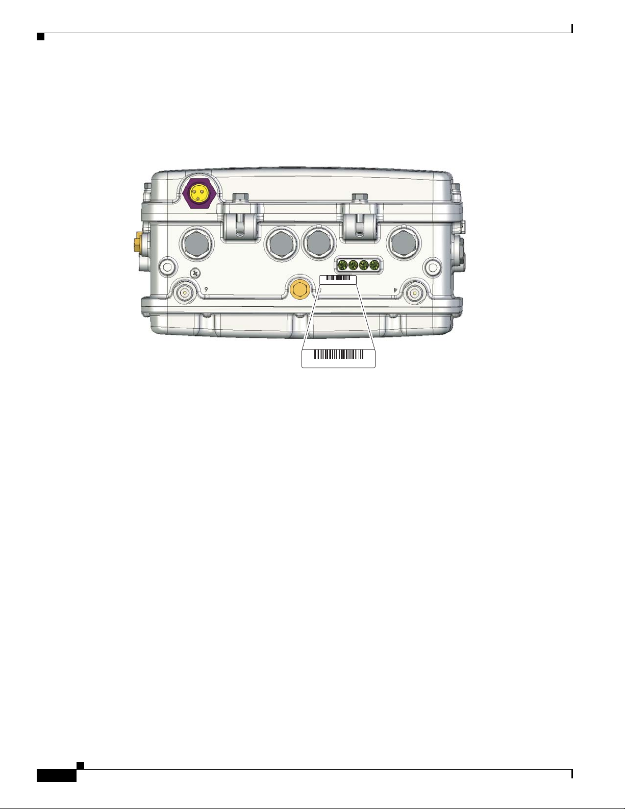
Finding the Product Serial Number
The access point serial number is on the bottom of the access point (refer to Figure 1).
Figure 1 Location of Serial Number Label
Preface
SN: NNNNNNNNN
SN: NNNNNNNNN
The access point serial number label contains the following information:
• Model number, such as AIR -LAP1 522AG-A-k9.
• Serial number, such as WCN0636279B (11 alpha numer ic digits).
• Access point MA C ad dress , such as 00abc65094f3 (12 hexadecimal digits). It is located to the right
of the serial number.
• Cable modem MAC address for cable configuration, such as 00abc7d094f9 (12 hexadecim al di gits ).
The cable modem MAC address is only available on the acce ss point cable configuratio n. It is
located below the serial number.
You need your product serial numb er when reque sting sup port from the Cisco Technical Assistance
Center.
Obtaining Documentation, Obtaining Support, and Security
Guidelines
For information on obtaining docume ntatio n, obtaini ng support , providing docum entat ion fee dback,
security guidelines, and also recommended aliases and general Cisco
What’s
New in Cisco Product Docume ntati on, w hic h also lis ts a ll new and revised C isco technical
documentation , at:
http://www.cisco.com/en/US/docs/general/whatsnew/whatsnew.html
documents, see th e monthl y
XIV
Cisco Aironet 1520 Series Outdoor Mesh Access Point Hardware Installation Guide
OL-12632-03
Page 15

CHA PTER
1
Overview
The Cisco Aironet 1520 Ser ies Outdoo r Mesh Acc ess Point (h ereaft er cal led the acce ss po int) is a
modularized wire less outdo or acce ss p oint desi gned f or use i n a m esh ne twor k. Th e ac cess po int a lso
supports wireless client acce ss, point-t o-point bridging, point-to- multipoin t bridging, and
point-to-multipoint mesh wir eless conne ctivity.
The LAP1522 model supports two radios (2.4-GHz and 5-GHz) and the LAP1524 model supports up to
4 radios (2.4-GHz, 5.8-GH z, and 4.9- GHz publi c safety ba nd). Both mo dels provide client acc ess
without the need for a license. The 5-GHz radios are dedicated to backhaul operations to reach a wired
network and the 2.4-GHz radio is used for wireless clients. The 4.9-GHz public safety band radio is used
for backhaul and access. The ac cess point can supp ort 6 to 54 Mb/s data rates.
The access po int is m a nufac tur ed in thre e configur ati on s: c ab le, po le mo unt, a nd me sh. The c abl e
configuration has three ant enna connectors on the top of the unit, can be mounted t o a cable strand, and
supports power-over-cable (POC). The pole mount configuration supp orts two antenn as on the top and
bottom of the unit. It can be moun ted to a pole or building wall and sup ports fiber-optic network s and
several power options. The Mesh con figuration ha s two a nten nas on the top a nd b ot tom of t he u nit. It
can be powered by AC and only supports wireless backhaul communications to reach the wired network.
It does not suppo rt h ar d-wi red co mm unic ation s ( ca ble , fiber-opti c, o r E the rnet ) to a wired ne twor k.
The access point is also available as a haza rdous loca tion opti on. When configured , the acc ess point
complies with safety st anda rd s for Cl ass I, Division 2, Z on e 2 haz ardo us loca ti ons i n wh ich igni ta ble
concentration s of flamma ble gase s, vapors, or liqui ds are not l ikely to exist under normal operat ion
conditions). When yo u select th e hazard ous locati on optio n as part of the or dering pr ocess, Cisc o
configures the system to conta in t he n ew component s. Two conduit adaptors and assembl y instruc tio ns
placed in the shipping box provide inf ormati on and assem bly procedu res.
The access point can also operate as a relay node for other access points not directly connected to a wired
network. Intelligent wireless routing is provided by the patented Adaptive Wireless Path Protocol
(AWPP). This enables each access point to identify its neighbors and intelligently choose the optimal
path to the wired netw ork b y ca lcula ting the c ost of e ach pa th in ter ms of signal str ength and the n umber
of hops required to g et to a c ont roll er.
The access point is configured, monitored, and operated through a Cisco wireless LAN controller
(hereafter ca lled a controller) as described in the Cisco Wireless LAN Controller Configuration Guide.
The Deployment Guide: Ci sco Mesh Netw orki ng Solu tion describes how to plan and initially configure
the Cisco mesh network, which supports wir eless point- to-point, point -to-mul tipoint, and me sh
deployments. The controllers use a browser-based management system, a command-line interface (CLI),
or the Cisco Wireless Control System (WCS) network management system to manage the controller and
the associated access points. The access point supports hardware-based advanced encryption standard
(AES) encryption between wireless nodes to provide end-to-end security.
OL-12632-03
Cisco Aironet 1520 Series Outdoor Mesh Access Point Hardware Installation Guide
1-1
Page 16
Hardware Features
This chapter provides information on the following topics:
• Hardware Features , pa ge 1-2
• Network Deployment Exam ples , page 1-11
Hardware Features
This section describe s the hardware features o f t he access point. Figure 1-1 , Figure 1-2, and Figure 1-3
show the access point connectors.
Note The illustrations in this document show all available connections for the access point. Unused
connections are capped with a connector plug to ensure the access point’s watertight integrity. Liquid
tight adapters are provided for connector openings, which can be installed be fore or after deploying the
access point.
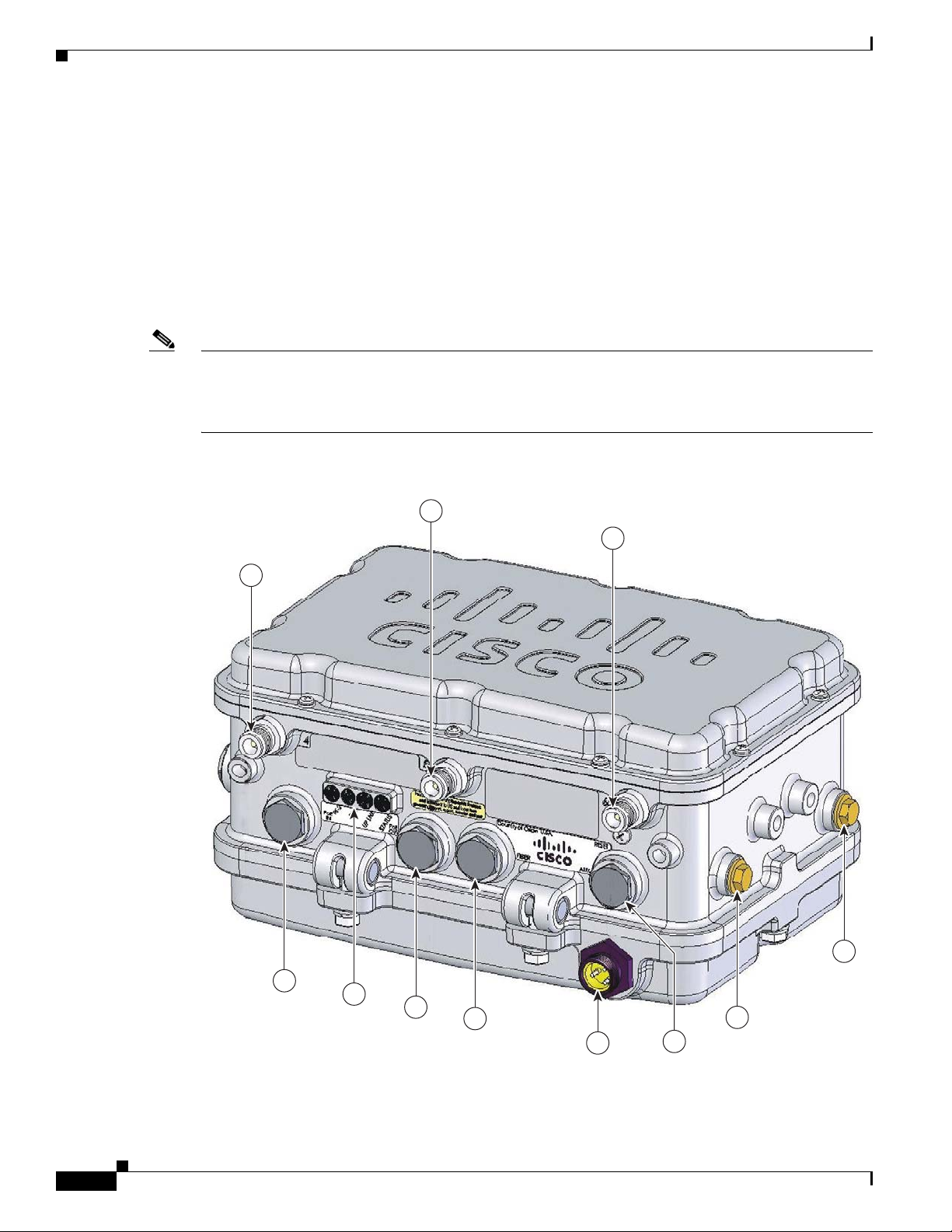
Figure 1-1 Access Point Bottom Connectors
Chapter 1 Overview
2
3
1
4
1-2
11
10
9
Cisco Aironet 1520 Series Outdoor Mesh Access Point Hardware Installation Guide
8
5
7
6
OL-12632-03
203822
Page 17
Chapter 1 Overview
Hardware Features
1 Antenna port 4 7 AC input connector
2 Antenna port 5 8 Fiber port
3 Antenna port 6 9 PoE out port
4 Fiber port (optional) 10 LEDs
5 Cable POC port (optional) 11 PoE in port
or
Cablegland entry (PG13) for connecti ng 230
Vac power supply
6 Aux/console p ort
or
Cablegland entry (PG13 ) for data cab le
(outdoor cat 5 STP cable)
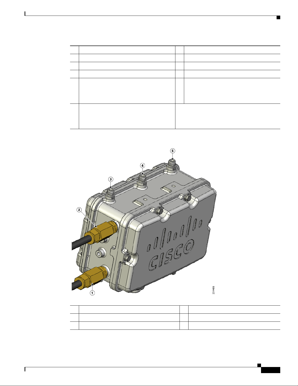
Figure 1-2 Cable, Fiber-Optic, and Antenna Connector Locations
OL-12632-03
1 Cable POC connec tor (o pti onal)
2 Fiber-optic connector3 (optional)
1
4 Antenna port 22 (Type N)
5 Antenna port 12 (Type N)
3 Antenna port 32 (Type N)
1. Stinger connector shown is user supplied.
2. Antenna locations depend upon access point configuration (see the “Antenna Connector Locations” section on page 1-6).
3. Liquid tight adapter not shown.
Cisco Aironet 1520 Series Outdoor Mesh Access Point Hardware Installation Guide
1-3
Page 18
Hardware Features
Chapter 1 Overview
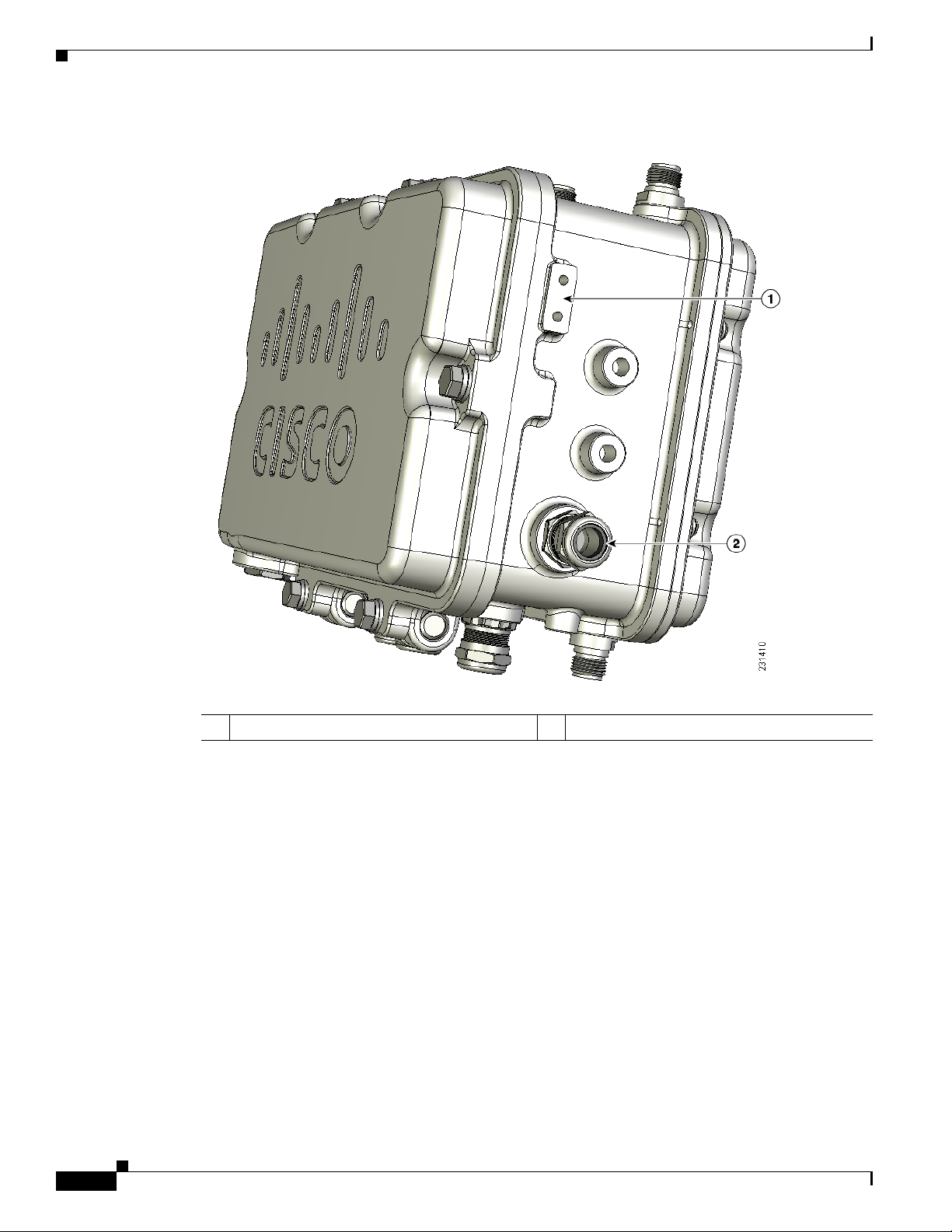
Figure 1-3 DC Power Connector and Ground Screw Holes
1-4
1 Ground screw holes 2 DC power connector
Figure 1-4 shows the antenna port locations for all models. The ports used depend on the model ordered.
Cisco Aironet 1520 Series Outdoor Mesh Access Point Hardware Installation Guide
OL-12632-03
Page 19
Chapter 1 Overview
Hardware Features
Figure 1-4 Antenna Port Locations
OL-12632-03
1 Antenna port 1 5 Hinge
2 Antenna port 2 6 Antenna port 5
3 Antenna port 3 7 Antenna port 6
4 Antenna port 4
Cisco Aironet 1520 Series Outdoor Mesh Access Point Hardware Installation Guide
1-5
Page 20

Hardware Features
Antenna Connector Locations
The access point is ma nufactur ed in thre e configurati ons, ca ble, me sh, and pole mount. Th ese
configurations support sp eci fic locat ions for the ac cess point an tenn as, as shown in
Ta b l e 1-1 Antenna Locations per Access Point Configuration
Chapter 1 Overview
Table 1-1.
Antenna
Port
Access Point Configurations
Cable Mesh and Pole Mount
1 2.4-GH z a nte nna con ne ctor (R X) 5-GHz antenna connector (TX/RX)
2 5-GHz antenna co nnecto r (TX/RX ) –
3 2.4-GH z a nte nna con ne ctor
1
2.4-GHz antenn a connec tor (RX)
(TX/RX)
4 –
5 –
6 –
1
1
1
2.4-GHz antenn a connec tor (RX)
1
–
2.4-GHz antenn a connec tor
(TX/RX)
1. Reserve d f or f utu re u se .
Some of the access point’s hardware features are listed below:
• Multiple radios (2.4- GHz, 5-G Hz, an d 4.9-G Hz)— see the “Multiple Radio Operation” section on
page 1-7
• External radi o anten nas —see the “Ext erna l Ant enna s” se ct ion o n page 1-7
• Multiple power sources—see the “Multiple Power Sources” section on page 1-8
• Ethernet ports —see the “Ethernet Ports” section on page 1-9
• Rugged metal enclosure—see the “Metal Enclosure ” sect ion on page 1-10
Connectors
Cisco Aironet 1520 Series Outdoor Mesh Access Point Hardware Installation Guide
1-6
• Optional cable modem—see the “Cable Mo dem” sec tio n o n page 1-10
• Optional hardware—see the “Optional Hardware” section on page 1-10
The optional featur es of the ac cess poin t support the se conne ctors (se e Figure 1- 1):
• PoE-in connector—internal RJ-45 with liquid tight adapter for waterproofing
• PoE-out connector—internal RJ-45 with liquid tight adapter for waterproofing
• Three, four, or six antenna c onne ctor s ( Type N)—depends on acc es s po int c onfigura tio n
• Fiber-optic connector—internal small form-factor pluggable (SFP) transceiver with LC connector
• Power-over-cable (POC) stinger connector—cu stome r provided
• AC power connector (3-pin Remke Mini-Link 5090 9)
• DC power connector— int erna l 2- pin c on ne ctor
OL-12632-03
Page 21

Chapter 1 Overview
Multiple Radio Operation
The access point supports 2.4-GHz and 5-GHz radios using external antennas (see “External Antennas”).
The LAP1522 model supp orts si mul tane ous dual -rad io ope rat ion u si ng a 2. 4-GH z 802 .11 b/g rad io an d
a 5-GHz 802.11a radio.The 5-GHz radio can operate in either the upper industrial, scientific and medical
(ISM) 5.8-GHz b and or the pu bli c saf ety 4. 9-GH z b an d. Th e 5- GHz rad io su ppo rts o ne a nte nna a nd is
used for backhaul operat ions to the co ntrolle r.
Note The 4.9-GHz band requires a license and can only be used by qualified public safety operators as defined
in section 90.20 of the FCC rules.
The 2.4-GHz radi o sup port s two or thre e a nte nnas f or sing le-in put , mu l tiple -out pu t (SI MO) op erat ion .
The access po int use s two o r t hre e rece ivers to su ppor t m axim um rat io co mbini n g (M RC) to e nh ance
receiver performance. MRC is a technique that combines the signals from multiple receivers in a
manner to optimize the rec eiv ed signal strength. MRC can provid e up to 3 dB of increased receiv e signa l
strength with two re c eive antennas o r up to 5 dB wi th th re e ante nn as.
Hardware Features
External Antennas
The access point supports up to three N-type radio frequency (RF) antenn a connectors on the top of the
unit and two on the bottom of the unit. The number of active antenna connectors depends upon the access
point configuration (see
supports multiple 2.4 -GHz ante nnas fo r MISO oper ation, but only on e 5-GHz ant enna.
When using the optional Cisco compact omnidirectional antennas, the 2.4- and 5-GHz antennas connect
directly to the access point. The Cisco omnidirectional antennas use vertical polarization.
Warning
Caution For directly mounted antennas, you must not add wea therpr oofing around the antenna conn ector s
Only trained and qualified personnel should be allowed to install, replace, or service this equipment.
Statement 1030
The access point has been designed to operate with the antennas listed below and with a maximum gain
of 8 dBi for 2.4 GHz and 17 dBi for 5 GHz. Antennas not in this list or with a higher gain are strictly
prohibited for use with the a ccess point . The requir ed ante nna impedan ce is 50 ohms.
To reduce po tent ia l ra dio int erfe renc e t o othe r use rs, the ant enn a type and it s ga in sh ould be cho sen so
that the equivalent isotropically radiated power (E.I.R.P.) is not more than required for successful
communication .
because the antenna drain ho les might be b locked and dam age the a ntenna .
Antenna Connector Locations, page 1-6). All ac cess point co nfigurat ions
OL-12632-03
Table 1-2 and Table 1-3 list the suppo rte d exte rnal ant enna s for the a ccess poi nt.
Ta b l e 1-2 External 5-GHz Antennas
Part Number Model
AIR-ANT5180V-N 5-GHz compact omnid irecti onal 8
AIR-ANT58G10SSA-N 5-GHz sector 9.5
Cisco Aironet 1520 Series Outdoor Mesh Access Point Hardware Installation Guide
1
Gain (dBi)
1-7
Page 22

Hardware Features
Chapter 1 Overview
Table 1-2 External 5-GHz Antennas
Part Number Model
AIR-ANT5114P-N 5-GHz patch 14
AIR-ANT5117S-N 5-GHz 90-degree sector 17
1. Operation in the 4.9-GHz band requires a license and may be used only by qualified Public Safety operators as defined in
section 90.20 of the FCC rules.
Ta b l e 1-3 External 2.4-GHz Antennas
Part Number Model Gain (dBi)
AIR-ANT2450V-N 2.4-GHz compact omnidir ectiona l 5.5
AIR-ANT2480V-N 2.4 GHz omnidirec tio nal 8
Multiple Power Sources
The access point supports these power sources:
• PoE—power injector (AIR -PWRIN J150 0-2=)
• AC power—100 to 480 VAC (standard power source for the pole moun t configurati on)
• POC—40 to 90 VAC (quasi-square wave AC), (standard power source for the ca ble c onfigurati on )
• External 12 VDC
1
Gain (dBi)
Warning
Connect the unit only to DC power source that complies with the safety extra-low voltage (SELV)
requirements in IEC 60950 based safety standards.
• Internal battery
Statement 1033
The access point can be connected to more than one power source. The access point detects the available
power sources and switches to the preferred power source using the following default prioritization:
• AC power or POC power
• External 12-VDC power
• Power injector PoE power
• Internal battery power
Warning
Caution To provide inline PoE, yo u m ust u se the 1 520 power inj ect or ( AIR -PW RINJ15 00- 2=). Ot her power
This unit might have more than one power supply connection. All connections must be removed to
de-energize the unit.
Statement 1028
injectors, PoE switches, and 802.3af power sources cannot provide adequate power, which can cause the
access point to malfunction and cause over-current conditions at the power source.
1-8
Cisco Aironet 1520 Series Outdoor Mesh Access Point Hardware Installation Guide
OL-12632-03
Page 23

Chapter 1 Overview
Caution The 1520 power injector (AIR-PWRINJ1500-2=) must be used in an indoo r environment only.
Note In the cable configuration, the cable modem is activated only when the access point i s powered by POC
Caution When the access point is installed outdoors or in a wet or damp location, the AC branch circuit that is
Hardware Features
or external 12 VDC p ower. When using only PoE power, the cable mo de m is de activated.
powering the access point should be provided with ground fault protection (GFCI), as required by Article
210 of the National Electrical Code (NEC).
The Ethernet cable from the power injector to the access point (PoE-in port) must be not less than 10 ft
(3.1 m).
The AC power cord options are listed below:
• 40-ft (15.2-m) power cord for light pole installations in the US and Canada. One end of the power
cord is terminated with an ac cess point AC power connector, and the other en d is termi nate d with
an AC plug (AIR-CORD -R 3P-4 0NA=).
Ethernet Ports
Note The PoE-out port is disabled when the a ccess point is powered by the power injector.
• 40-ft (15.2-m) power cord for light pole installations in the European Union. One end of the power
cord is terminated w ith an ac cess point AC power connector, and the other en d is unterm inate d.
Users must install a plug that is certified for outdoor use and that it has a minimum IP67 rating, such
as Interpower 8413125 1 o r Hu bbel l H BL316 P6W (I EC/E N6030 9) pin- an d-s leeve type con ne ctor s
(AIR-CORD-R3P-4 0UE= ).
• 4-ft (1.2-m) streetlight power tap adapter for light pole installations in the US and Canada
(AIR-PWR-ST-LT-R3P=).
The access point supports a PoE-in port and a PoE-out port. The access point’s PoE-in port uses an RJ-45
connector (with a liquid tight adapter) to link the access point to the 10/100/1000BASE-T network. The
Ethernet cable is used to send and receive Ethernet data and to optionally supply inline 56-VDC power
from the power injector.
The access poin t’s PoE-out (10/10 0/100 0BASE-T) port uses a n RJ-45 co nne cto r (w ith a li qu id ti ght
adapter) to pr ovide L A N c onn ect ivity and IE EE 802 .3a f power to a singl e pe riph er al cu st omer device,
such as a camer a or senso r ga teway. The PoE-out port shoul d not be c on necte d to a swit ch or h ub.
The Ethernet MAC addresses is printed on the bottom of the access point under the LEDs (refer to the
“Finding the Product Serial Number” section on page XIV).
OL-12632-03
Warning
To reduce the risk of fire, use only No. 26 AWG or larger telecommunication line cord.
Statement 1023
The Ethernet cabl e m ust be a shie lde d outdo or rat ed Ca tegory 5e (C AT5e) or better cable. The a c cess
point senses the Ethernet and power signals and automatically switches internal circuitry to match the
cable connections.
Cisco Aironet 1520 Series Outdoor Mesh Access Point Hardware Installation Guide
1-9
Page 24

Hardware Features
Caution To provide inline PoE, yo u m ust u se the 1 520 power inj ect or ( AIR -PW RINJ15 00- 2=). Ot her power
Cable Modem
Note The access point uses a Scientific Atlanta DPC2100 cable modem board and 4015821 RF splitter.
Chapter 1 Overview
injectors, PoE switches, and 802.3 af power sources can not provide ad equa te power, which may cause
the access point to malfunction and cause possible over-current conditions at the power source.
The access point cable configuration contains an internal cable modem for connection to the cable
network from the pole-mount ed cabl e lines. Th e acc ess point can be powered using the 40 -to 90-VAC
(quasi-square wave AC) power provided by the cable network.
The cable modem supports these main features:
• Data Over Cable Service Interface Specifications (DOCSIS) 2.0
• Backward compatibility with existing DOCSIS 1.1 and 1.0 networks
Metal Enclosure
The access po int uses a me tal en cl osure th at ca n acco mm oda te bo th in door or o utdoo r ope rat ing
environments and an industria l tem pera ture op erat ing ra nge of –40 to 13 1°F (– 40 to 55°C ). The a cce ss
point complies with NEM A 4 and IP67 requ ireme nts.
Optional Hardware
Some of the access point hardware options are listed below:
• Fiber-optic module and t ake-up ree l kit (GL C- FE- 100BX -URG D=) —Sma ll for m- factor p lugga ble
(SFP) module for connection to fiber-optic lines. The take-up reels are used to store excess
fiber-optic cable by wrapping the c able ar ound the re els.
–
–
–
–
–
• Pole mount kit (AIR-ACCPMK15 20=)—provides hardware for mounting the access point to a metal
or wood pole, su ch a s a stre etl ight pol e.
• Strand mount kit (A I R-ACCSMK1520=)— provide s har dware fo r mou nting t he a ccess p oi nt to a
cable strand.
Single strand fiber bidirectiona l optical tra nsceiver
1.3 (transmit) /1. 5 ( rec eive) microm ete r wavelength division mu ltip lexing ( WD M) f unc tion
100 Mb/s data rates
LC receptacle
Supports up to 15.5 mi (25 km) of fiber-optic cable.
1-10
• Streetlight power tap ad apter (AIR-PWR-ST-LT-R3P=)—c onnects to the l ight control con nector on
a streetlight pole and provides AC power to the access point.
• 1520 power injecto r (AIR-PWRINJ1500-2=)—provides PoE to the access point.
Cisco Aironet 1520 Series Outdoor Mesh Access Point Hardware Installation Guide
OL-12632-03
Page 25

Chapter 1 Overview
• 40-ft (12.2-m) power cord for light pole installations in the US and Canada
(AIR-CORD-R3P-40NA=)—provides AC power to the access point. One end of the power cord is
terminated with an access point AC power connector, and the other end is terminated with an AC
plug.
• Battery backup m odu le (AIR- 152 0-BATT-6AH). The integrated battery c an be u sed f or tem porar y
backup power during external power interr uption s.
–
3- hour access po in t op er ati on us ing two ra dio s a t 77oF (25oC)—with PoE output port off
–
2-hour access point operation usi ng two radios at 77oF (25oC)— with PoE outpu t po rt on
• banding strap tool (BAND IT) (AIR-BAND-INST-TL=)—used to install the metal straps used in
pole mounting.
Network Deployment Examples
The access poin t is a wir eless d evice desi gned fo r wir eless c lien t a cce ss and po int -to-p oint bri dgin g,
point-to-multipoint bridging, and point-t o-multi point mesh w ireless con nectivity. The access point
provides 5-GHz back ha ul c apab ilit y to li nk wi th a not her ac cess point to r eac h a wir ed ne twork
connection or to provide repeat er operat ions for other access points.
Network Deployment Examples
The access point plays one of two primary radio roles: a root access point (hereafter called a RAP) or the
access points that relay their wireless connections to the controller are called mesh access points
(MAPs). When the access point has a wired Ethernet, fiber-optic, or cable connection to the controller
(through a switch), th e ra dio role is ca lled a RAP. A RAP is a parent node to any br idgi ng or m e sh
network. A controller can support one or more RAPs, eac h one parenting the same or different wireless
networks. There can be more th an one RAP fo r the same m esh ne twork f or re dun dancy. Both RAP and
MAP access points can su pport wi reless clie nts using the 2.4- GHz rad io.
Note The access point must be configured as a RAP in the controller, whereas the MAP role is a default
setting.
When the access point does not have a wired Ethernet, fiber-optic, or cable connection to the controller,
the radio role is called a MA P. The MAPs have a wireless con nection (t hroug h the back haul inte rface)
to other MAPs and finally to a RAP with an Ethernet or cable connection through a switch to the
controller. MAPs can also have a wired Ethernet connect ion to a lo cal LAN and serve as a bridg e
endpoint for t hat LAN (usi ng a p oin t-to- poin t or po i nt-to- mul tipoi n t br idge conn ec ti on).
OL-12632-03
Cisco Aironet 1520 Series Outdoor Mesh Access Point Hardware Installation Guide
1-11
Page 26

Network Deployment Examples
(2.4 Ghz)
148440
Wireless Backhaul
The access point supports wireless backhaul capability using the 5-GHz radio to bridge to another access
point to reach a wired net work conne ction to a contro ller (see
to the wired network is considered a RAP in this configuration. The remote access point is considered a
MAP and transfers wireless client traffic to the RAP for transfer to the wired network. Lightweight
access point prot ocol (LWAPP) control traffic is also tran sfer re d over this bri dg ed l ink .
Figure 1-5 Access Point Backhaul Example
Chapter 1 Overview
Figure 1-5). The access point connected
(5.8 Ghz)
148438
Point-to-Point Bridging
The access points can be used to extend a remote network by usin g the 5-GHz backhaul radio to bridge
the two network segments as shown in
bridging on the controller for each acc ess point.
Figure 1-6 Access Point Point-to-Point Bridging Example
Figure 1-6. To support Et herne t b ridging , you m ust e nabl e
1-12
Cisco Aironet 1520 Series Outdoor Mesh Access Point Hardware Installation Guide
OL-12632-03
Page 27

Chapter 1 Overview
Point-to-Multipoint Bridging
The access points can be used as a RAP to connect multiple remote MAPs with their associated wired
networks (see
Ethernet bridging, you mu st enable br idging on the controller for each acc ess point.
Wireless client access can be provided over the bridging link; however, if bridging between tall
buildings, the 2.4-GHz w irele ss coverage are a m ight b e li mited and pos sibl y n ot su itable f or di rec t
wireless client access.
Figure 1-7 Access Point Point to Multipoint Bridging Example
Figure 1-7). By default, this capability is turned-off for all access points. To support
Network Deployment Examples
Mesh Network
148439
The access points are typically deployed in a mesh network configuration. In a typical mesh deployment,
one or more RAPs have a wired network connection through a switch to a controller. Other remote MAPs
without wired network connections use the backhaul feature to optimally link to a RAP that is connected
to the wired network. In the mesh network, the links between the access points are referred to as the
backhaul links.
Intelligent wireless routing is provided by the patented Adaptive Wireless Path Protocol (AWPP). This
enables each MAP to identify its neighbors and intelligently choose the optimal path to the RAP with
the wired network co nnec tio n by c alcul at ing the co st of e ach pat h in t erm s o f sig na l stre ngth a nd the
number of hops required to get to a controll er.
Figure 1-8 illustrates a typical mesh configuration using MAPs and RAPs.
OL-12632-03
Cisco Aironet 1520 Series Outdoor Mesh Access Point Hardware Installation Guide
1-13
Page 28

Network Deployment Examples
Figure 1-8 Typical Mesh Configuration Using Access Points
Chapter 1 Overview
IP
155631
1-14
Cisco Aironet 1520 Series Outdoor Mesh Access Point Hardware Installation Guide
OL-12632-03
Page 29

Chapter 1 Overview
158085
Layer 3 Network Operation
The access poin ts su ppor t L ay er 3 ne twork ope ratio n. A ccess p oi nts a nd cont r oller s in La yer 3
configurations use IP addresses and UDP packets, which can be routed through large networks. Layer 3
operation is scalable and recommended by Cisco.
Figure 1-9 illustrates a typical Layer-3 wireless network configuration containing access points and a
controller.
Figure 1-9 Typical Layer 3 Access Point Network Configuration Example
Network Deployment Examples
LWAPP
LWAPP
OL-12632-03
Cisco Aironet 1520 Series Outdoor Mesh Access Point Hardware Installation Guide
1-15
Page 30

Network Deployment Examples
Chapter 1 Overview
1-16
Cisco Aironet 1520 Series Outdoor Mesh Access Point Hardware Installation Guide
OL-12632-03
Page 31

CHA PTER
2
Mounting Instructions
This chapter describes warnings, safety information, and mounting information needed during the
installation of your ac cess point . The chap ter co ntains these secti ons:
• Unpacking the Access Po int, page 2-2
• Tools and Ma ter ials Tha t You Supply, page 2-2
• Warnings, page 2-4
• Safety Informa tion, p ag e 2-4
• Avoiding Damage to Radios i n a Testing Environment, page 2-7
• Installation Guidelines, page 2-8
• Mounting the Access Point, page 2-16
• Grounding the Access Point , pa ge 2-42
• Connecting a Fiber-Optic Cable to the Access Point, page 2-43
• Powering the Access Point, page 2-46
• Installing the Access Point in Hazardou s Location s, page 2-60
OL-12632-03
Cisco Aironet 1520 Series Outdoor Mesh Access Point Hardware Installation Guide
2-1
Page 32

Unpacking the Access Point
Unpacking the Access Point
When you are unpacking the access point, do not remove the foam blocks attached to the antenna
connectors. The foam protects the antenna connectors during installation.
Follow these steps to unpack the access point:
Step 1 Open the shipping container and carefully remove the contents.
Step 2 Return all pack i ng ma ter ials t o t he sh i pping cont ai ner, and save it.
Step 3 Ensure that all items listed in Package Contents are included in the shipment. If any item is damaged or
missing, notify your authori zed Cisco sales repr esenta tive.
Package Contents
Each access point pack age co ntain s the foll owing items:
• Access point
Chapter 2 Mounting Instructions
• Cisco product documentat ion and tran slated safe ty warnings
• Grounding lug wit h two screws and loc k washe rs
• Three liquid tight adapters
• Two-pin DC power connecto r
• Ground lug (Panduit PLCD6-10A -L) and screws with loc k washers
Tools and Materials That You Supply
• Ground lug crimping too l (Panduit CT-720 with CD-720-1 die)
• 6-AWG copper ground wi re
• 13 mm box-end w r en ch or so cket set
• Adjustable wrench, 22 mm socket, or Sealcon S-2200-WR socket wrench
• Small flat screwdriver for DC power co nnec tor
• Optional power injector ( AIR- PWR INJ1 500 -2=)
• Optional AC power cord
–
40-ft (12.2-m) power cord (AIR-CORD-R3P-40NA=) for light pole installations in the US and
Canada
–
4-ft (1.2-m) streetli ght power tap adap ter (AIR -PWR-ST-LT-R3P=) for light pole insta llati ons
in the US and Canada
• Antennas, 2.4 and 5 GHz (refe r to the “ External Antennas ” sec tion on page 1-7)
2-2
• Optional pole mount kit (AIR-ACCPMK1520=)
• Optional strand moun t ki t ( AIR- ACCSMK1520=)
• Optional banding stra p to ol ( BAND IT) (A IR- BAND-INST-TL=)
Cisco Aironet 1520 Series Outdoor Mesh Access Point Hardware Installation Guide
OL-12632-03
Page 33

Chapter 2 Mounting Instructions
• Optional fiber-optic 100BASE-BX10-U SFP, fiber-optic take-up reels, and liquid tigh t a dapter
• Optional outdoor-rated fiber-optic cab le with 0. 20 to 0 .35 in. (0. 51 to 0 .89 cm) d iame te r
• Optional shielded outdo or-rate d Et herne t ( CAT5e or better) cable with 0. 20 to 0.3 5 in
• Optional Ethernet RJ-45 connec tor and in stalla tion tool
• Optional shielde d outdo or-rate d DC power ca ble w ith 0.2 0 t o 0. 35 in. ( .0.51 t o 0.89 c m ) d iam ete r
• Optional cable Stinger connector
• Optional ground rod, as requi red by local regula tions
• Optional ladder, power lift, rop e, o r o the r to ol s as r e quire d
Pole Installation
To install the acce ss point on a vertical or horizon tal metal, wood , or fiberglass pole, you nee d the
following additional ma teria l a nd t ools:
Tools and Materials That You Supply
(GLC-FE-100BX-U R GD= )
(0.51 to 0.89 cm) diame ter
• Pole mount kit (AIR-ACCPMK1520= )
–
Pole clamp bracket
–
Two gusset strap brac kets
–
One mounting b racket
–
Twelve hex bolts ( M 8 x 16)
–
One M8 flange nut
–
Six M8 flat washers
–
Ten M8 split lock washers
–
Two stainless steel mount ing straps
• Customer banding strap tool (BAND IT)—(AIR-BAND-INST-TL=)
• Customer supplied 13-mm and box -end wrenc h or socket set
• Customer supplied adju stable wr ench , 22 mm socket, or Sealcon S-2200-WR socket wren ch
Cable Strand Installation
To install the acce ss point on a cab le strand, you need the following addi tional pa rts:
• Cable strand mount kit (AIR-ACCSMK1520=)
–
Strand mounting bracket
–
Strand clamp bracket
OL-12632-03
–
Four cable clamps
–
Four M8 flange n uts
–
Four hex bolts (M8 x16)
–
Four M8 split lock washers and six M8 flat washe rs
Cisco Aironet 1520 Series Outdoor Mesh Access Point Hardware Installation Guide
2-3
Page 34

Warnings
Warnings
Chapter 2 Mounting Instructions
• Customer supplied 13-mm box-end wrench or socket set
• Customer supplied adju stable wr ench , 22 mm socket, or Sealcon S-2200-WR socket wren ch
Translated v ersions of all safety wa rnings are a vailable in the safety warning document that shipped with
your access poin t or on Cisc o.co m. To browse to the documen t on Cisc o. co m, re fer to
“Translated Safety Warnings” for instructions.
Appendix A,
Warning
Warning
Warning
Warning
Warning
IMPORTANT SAFETY INSTRUCTIONS
This warning symbol means danger. You are in a situation that could cause bodily injury. Before you
work on any equipment, be aware of the hazards involved with electrical circuitry and be familiar
with standard practices for preventing accidents. Use the statement number provided at the end of
each warning to locate its translation in the translated safety warnings that accompanied this device.
Statement 1071
SAVE THESE INSTRUCTIONS
Do not operate the unit near unshielded blasting caps or in an explosive environment unless the
device has been modified to be especially qualified for such use.
This equipment must be externally grounded using a customer-supplied ground wire before power is
applied. Contact the appropriate electrical inspection authority or an electrician if you are uncertain
that suitable grounding is available.
Read the installation instructions before connecting the system to the power source.
Ultimate disposal of this product should be handled according to all national laws and regulations.
Statement 1040
Statement 364
Statement 366
Statement 1004
Safety Information
Follow the guidelines in this section to ensure proper operation and safe use of the access point.
FCC Safety Compliance Statement
The FCC, with its action in ET Doc ket 96-8, has adop ted a safe ty standard for human exposur e to RF
electromagnetic energy emitted by FCC-certified equipment. When used with approved Cisco Aironet
antennas, Cisco Aironet products meet the uncontrolled environmental limits found in OET-65 and ANSI
C95.1, 1991. Proper operation of this radio device according to the instructions in this publication results
in user exposure substantially below the FCC recommended limits.
Cisco Aironet 1520 Series Outdoor Mesh Access Point Hardware Installation Guide
2-4
OL-12632-03
Page 35

Chapter 2 Mounting Instructions
Safety Precautions
Safety Information
Warning
Warning
Warning
Warning
Warning
Warning
The AC power supply has double pole/neutral fusing.
Statement 188
Do not work on the system or connect or disconnect cables during periods of lightning activity.
Statement 1001
Class 1 laser product.
Statement 1008
There is the danger of explosion if the battery is replaced incorrectly. Replace the battery only with
the same or equivalent type recommended by the manufacturer. Dispose of used batteries according
to the manufacturer’s instructions.
Statement 1015
A readily accessible two-poled disconnect device must be incorporated in the fixed wiring.
Statement 1022
To reduce the risk of fire, use only No. 26 AWG or larger telecommunication line cord.
Statement 1023
Warning
Warning
Warning
Warning
This unit might have more than one power supply connection. All connections must be removed to
de-energize the unit.
Statement 1028
Only trained and qualified personnel should be allowed to install, replace, or service this equipment.
Statement 1030
Connect the unit only to DC power source that complies with the safety extra-low voltage (SELV)
requirements in IEC 60950 based safety standards.
Statement 1033
When installing or replacing the unit, the ground connection must always be made first and
disconnected last.
Statement 1046.
OL-12632-03
Cisco Aironet 1520 Series Outdoor Mesh Access Point Hardware Installation Guide
2-5
Page 36

Safety Information
Chapter 2 Mounting Instructions
Warning
Do not locate the antenna near overhead power lines or other electric light or power circuits, or
where it can come into contact with such circuits. When installing the antenna, take extreme care
not to come into contact with such circuits, because they may cause serious injury or death. For
proper installation and grounding of the antenna, please refer to national and local codes (for
example, U.S.:NFPA 70, National Electrical Code, Article 810, Canada: Canadian Electrical Code,
Section 54).
Caution Before connecting or disconnecting a power cord, you must remove AC power from the power cord using
Statement 1052
a suitable servic e disconn ect .
For additional importa nt safety instructions for AC power cords, refer to the AC Power Cords for Cisco
Aironet 1520 Series Outdoor Mesh Access Points document that shipped with you r AC power cords.
For safety and to achieve a good installation, please read and follow these safety precautions:
1. Select your installation site with safety, as well as performance in mind. Remember: electric power
lines and phone lines look alike. For safety, assume that any overhead line can kill.
2. Call your electric power company. T ell them your plans, and ask them to come look at your proposed
installation.
3. Plan your installation ca refu lly a nd co mp let ely befo re you begin. Suc cessf ul r aisi ng of a ma st or
tower is largely a matter of coordination. Each person sh ould be assign ed to a specific tas k and
should know what to do and when to do it. One person should be in charge of the operation to issue
instructions and watc h for sign s o f troub le.
4. When installing the access point and antennas, remember:
a. Do not use a meta l lad der.
b. Do not work on a we t or wi ndy day.
c. Do dress properly—shoes with rubber soles and heels, rubber gloves, long sleeved shirt or
jacket.
5. Use a rope to lift the access point. If the assembly starts to drop, get away from it and let it fall.
6. If any part of the antenna system should come in contact wi th a power line, do not touch it or try to
remove it yourself. Call your local power company. They will remove it safely.
If an accident should occur, call for qualified emergency help immediately.
2-6
Cisco Aironet 1520 Series Outdoor Mesh Access Point Hardware Installation Guide
OL-12632-03
Page 37

Chapter 2 Mounting Instructions
Avoiding Damage to Radios in a Testing Environment
Avoiding Damage to Radios in a Testing Environment
The radios on outdoor units (bridges) have higher transmit power levels than radios on indo or units
(access points). When you t est high power radios in a lin k, you must avoid exceeding the rec eiver’s
maximum receive input level. At levels above the normal operatin g range, pa cket erro r rate (P ER)
performance is degraded. At even higher levels, the receiver can be permanently damaged. To avoid
receiver damage and PER degrada ti on, you ca n use o ne of t he fol lowing t echn ique s:
• Separate the omnidirectional antennas by at least 2 ft (0.6 m) to avoid receiver damage or by at least
25 ft (7.6 m) to avoid PER degradation.
Note These distance s assum e fre e space path loss and ar e cons ervative estimate s. Requi red
separation distances for damage and performance degradation levels in actual deployments are less if
conditions are not non line-of-sight.
• Reduce the configured transmit power to the minimum level.
• Use directional antennas, and keep them away from each other.
• Cable the radios together using a co mbination of attenuators, c ombiners, or splitters to achie ve a total
attenuation of at least 60 dB.
For a radiated test bed, the foll owing equation descr ibes the relationships among transmit po wer , antenna
gain, attenuation, and receiver sensitivity:
txpwr + tx gain + rx gain - [attenuation due to antenna spacing] < max rx input level
Where:
txpwr = Radio transmit power level
tx gain = transmitter antenna gain
rx gain = receiver antenna gain
For a conducted test bed, the fol lowing equation describes th e relations hips am ong transm it power,
antenna gain, and rec eiver sensitivity:
txpwr - [attenuation due to coaxial components] < max rx input level
Caution Under no circumstances should you con nec t t he ant enna por t from one ac cess po int to the ant enna port
of another access po int wi thou t using a n RF att enua tor. If you connec t a ntenna ports, y ou mu st no t
exceed the maximum survivable receive level of 0 dBm. Never exceed 0 dBm, or damage to the access
point can occur . Using attenuato rs, combiners, and splitters hav ing a total of at least 60 dB of att enuation
ensures that the receiver is not damaged and th at PER perf orma nce is not degrade d.
OL-12632-03
Cisco Aironet 1520 Series Outdoor Mesh Access Point Hardware Installation Guide
2-7
Page 38

Installation Guidelines
Installation Guidelines
Because the access point is a radio device, it is susceptible to common causes of interference that can
reduce throughpu t a nd ra nge . Foll ow these b asic gu ide lin es t o ensu re the b es t pos sibl e perfo rm an ce:
• For information on planning and initially configuring your Cisco Mesh network, refer to the
Deployment Guid e: Ci sco Mes h N etw or king So lut ion.
• Perform a site survey before beginning the inst allat ion.
• Install the access point in an area where structures, trees, or h ills do not obstruct rad io signals to and
from the access point.
• The access points can be installed at any height, but best throughput is achieved when all the access
points are mount ed at the same hei ght. We recommends installi ng the a cce ss p oints no high er tha n
40 feet to allow support for wireless clie nts on the gro und.
Note To calculate path loss and to determine how far apart to install access points, consult an RF planning
expert.
Chapter 2 Mounting Instructions
Site Surveys
Every network application is a unique installation. Before installing multiple access points, you should
perform a site survey to determine the optimum use of network ing components a nd to maximize range,
coverage, and network p erfor ma nce.
Consider the following operating and environmental conditions when performing a site survey:
• Data rates—Sensitivity and range are inversely proportiona l to data bit rat es. The ma ximum ra dio
range is achieved at the lowest workable data rate. A decrease in receiver sensitivity occurs as the
radio data increases.
• Antenna type and placement—Proper antenna configuration is a critical factor in maximizing radio
range. As a general ru le, ra nge in cr ease s in p rop ortio n to an te nna he ig ht. However, do not place the
antenna higher than necessary, because the extra height also increases potential interference from
other unlicensed rad io sy stem s a nd de cr ease s th e wir eless c overage f rom t h e gro und .
• Physical environment—Clear or op en are as pr ovide b ett er r ad io r an ge t han cl os ed or filled ar eas.
• Obstructions—Physical obstructions such as buildings, trees, or hills can hinder performance of
wireless devices. Av oid locating the devices in a location wh ere th er e is a n ob struction between the
sending and receiving ante nnas.
2-8
Cisco Aironet 1520 Series Outdoor Mesh Access Point Hardware Installation Guide
OL-12632-03
Page 39

Chapter 2 Mounting Instructions
Before Beginning the Installation
Before you begin the installation process:
• Ensure that a site survey has been perfo rmed .
• Ensure that your network i nfrastr ucture devices are opera tiona l and prope rly co nfigured.
• Ensure that your cont rollers ar e conne cted to s witch trunk ports.
• Ensure that your switch is configured with untagged access ports for connecting your access points.
• Ensure that a DHCP server with Option 43 configured is reac hable by your acc ess points , or
manually configure the controller information in the access point (for additional information, refer
to the
“Configuring DHCP Option 43” section on pa ge F-1).
• Become familiar with the access point installation components (see the “Becoming Familiar with
Access Point Installation Components” section on page 2-9).
Becoming Familiar with Access Point Installation Components
The access point is designed to be installed in an indoor or outdoor environment, such as an interior wall
or ceiling or the exterior roof overhang of a tall building or a streetlight pole. Carefully review the
following f igures to be come familiar with the system compone nts, connectors , indicators, cables, system
interconnection, and gro unding:
Installation Guidelines
• Components in a typical access point installation (see Figure 2-1)
• Pole mount installa tion ( se e Figure 2-2)
• Cable strand mount install ation (se e Figure 2-3 )
• Streetlight power tap installation (see Figure 2-4)
Note The illustrations in this document show all available connections for the access point. Unused
connections are capped with a connector plug to ensure the access point’s watertight integrity. liquid
tight adapters are provided for connector openings, which can be installed be fore or after deploying the
access point. The illustrations do not show antenna port 5, which is reserved for future use.
OL-12632-03
Cisco Aironet 1520 Series Outdoor Mesh Access Point Hardware Installation Guide
2-9
Page 40

Installation Guidelines
231523
Chapter 2 Mounting Instructions
Figure 2-1 Components in a Typical Access Point Installation
1
2
10 8
9
3
7
4
5
6
1 Building roof-overhang 6 Ground
2 Shielded outdoor-rated Et hern et
(CAT5e or better) cable
1
7 AC power cord
3 Water drip loop 8 Power injector
4 6-AWG copper gr ou nding w ire1 9 Shielded Ethernet (CAT5e or better) cable
2
3
1
5 Ground rod1 10 Controller (through a switch)
1. User suppl ie d.
2. The safety ground wire in the AC power cord must have a ground path to a grounding rod.
3. The shielded Ethernet cable has a ground path through the power injector and the safety ground wire in the AC power cord.
2-10
Warning
Cisco Aironet 1520 Series Outdoor Mesh Access Point Hardware Installation Guide
Installation of the equipment must comply with local and national electrical codes.
Statement 1074
OL-12632-03
Page 41

Chapter 2 Mounting Instructions
Figure 2-2 Pole Mount Installation
Installation Guidelines
OL-12632-03
1 Stainless steel mounting straps
4 2.4-GHz antennas
(part of pole mount kit)
2 2.4-GHz antenna
3 5-GHz antenna
1. Illustration shows antennas for an access point with two radios.
1
1
Cisco Aironet 1520 Series Outdoor Mesh Access Point Hardware Installation Guide
5 Pole (wood, metal, or fiberglass)
6 Mounting bracket ( part o f pol e m oun t ki t)
1
2 to 16 in. (5.1 t o 40. 6 cm ) dia meter
2-11
Page 42

Installation Guidelines
Chapter 2 Mounting Instructions
Figure 2-3 Cable Strand Mounting
2-12
1 Clamp bra cket w ith c ab le cl am p s
5 Cable bundle
(part of strand mount kit)
2 5-GHz antenna
3 2.4-GHz antennas
1
1
6 Fiber-optic connection
7 Cable POC power input
4 Strand support cabl e 8 Strand mount bracket
1. Illustration shows antennas for an access point with two radios.
2. Liquid tight connector not shown.
3. Stinger connector shown is user supplied.
Cisco Aironet 1520 Series Outdoor Mesh Access Point Hardware Installation Guide
2
3
(part of strand mount kit)
OL-12632-03
Page 43

Chapter 2 Mounting Instructions
231524
Figure 2-4 Streetlight Power Tap Adapter Installation
Installation Guidelines
1
1 Outdoor light co ntro l 3 6-AWG copper g rou ndi ng w ire
2 Streetlight power tap adapter
Antenna Connector Locations
The access point is ma nufactur ed in thre e configurat ions , cable , pole moun t, and mes h. These
configurations support sp eci fic locat ions for the ac cess point an tenn as as shown in
Ta b l e 2-1 Antenna Locations for Each Access Point Configuration
2
3
Table 2-1.
1
Antenna
Port
Access Point Configurations
Cable Pole Mount and Mesh
1 2.4-GHz antenna conn ec tor (R X) 5-GHz antenna connector (TX/RX)
2 5-GHz antenna connector (TX/RX) 2.4-GHz antenna conn ec tor ( Rx)
3 2.4-GHz antenna conn ec tor (TX /RX ) 2.4-GHz antenna c onn ect or (Tx/ RX)
4 –
5 –
6 –
1. Antenna locations specified for a two radio access point.
2. Reserved for future use. A plug is installed.
2
2
1
2.4-GHz antenna c onnec to r ( RX )
2
–
4.9-GHz antenna conn ec tor (TX /RX )
OL-12632-03
Cisco Aironet 1520 Series Outdoor Mesh Access Point Hardware Installation Guide
2-13
Page 44

Installation Guidelines
Chapter 2 Mounting Instructions
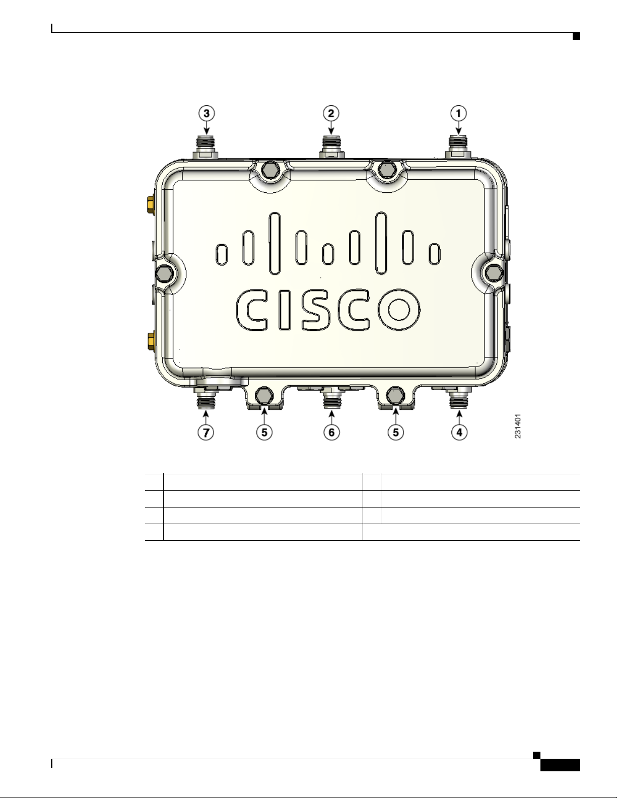
Figure 2-5 shows the ant enn a por t l ocati on s v iewed from t he hinge d cover side .
Figure 2-5 Antenna Port Locations
1 Antenna port 1 4 Antenna port 4
2 Antenna port 2 5 Antenna port 5
3 Antenna port 3 6 Antenna port 6
Adding the Access Point MAC Addresses to the Controller Filter List
Before installing your acc ess points , configure you r controll er by adding the M AC addresses of the
access points to the fil ter list. MAC address filtering is enabled by def ault. This enab les the co ntrolle r to
respond to the listed access points. Follow these steps to add a MAC filter entry on the controller:
Step 1 Log into y our cont rol ler usin g a w eb browser.
Step 2 Choose SECURITY > MAC Filtering > New.
Step 3 Enter the MAC address of the access point to the MAC Filter list; for example, 00:0B:91:21:3A:C7.
Note The access point MAC address is located on the bottom of the unit. When two MAC addresses
are shown, use the top MAC address.
Step 4 Select a WLAN ID or Any WLAN from the WLAN ID pop-up menu.
Step 5 Enter a description (32 characters maximum) of the access point in the Description field; for example,
Fisher_Street_00.0B.91.21.3A.C7 shows t he lo cat ion an d MAC address of th e acc ess point .
2-14
Cisco Aironet 1520 Series Outdoor Mesh Access Point Hardware Installation Guide
OL-12632-03
Page 45

Chapter 2 Mounting Instructions
Step 6 Choose an interface from the Interface Name pop-up menu, and click Apply.
Step 7 Repeat Steps 2 to 6 to add othe r access points to th e list.
Step 8 Log out o f you r c on troll er, and close y our w eb b rowser.
Configuring a RAP
The access point defaults to the MAP radio role. One or more of your access points must be reconfigured
as a RAP. The RAPs connect to a wired Ethernet link through a switch to the controller. The MAPs use
their wireless backhaul interface to connect to a RAP to reach the controller.
Follow these steps to configure a RAP on the controller GU I:
Step 1 Log into y our cont rol ler usin g a w eb browser.
Step 2 Click Wireless. When your access point associates to the controller, your access point’s name appears
in the AP Name list.
Installation Guidelines
Step 3 Double-click yo ur a ccess po int ’s name.
Step 4 Find Mesh Informa tion, and c hoose Ro ot A P by clicking th e drop down arrow in the AP Role field.
Step 5 Click Apply.
Step 6 Repeat Steps 2 through 5 for each RAP.
Step 7 Log out from your controller, and close your web browser.
Configuring a Bridge Group Name
The bridge group name (BGN) controls the association of the access points to a RAP . BGNs can be used
to logically group the radios to avoid different networks on the same channel from communicating with
each other. This setting is al so use ful i f you have more tha n on e R AP in yo ur n etwork i n the s am e are a.
If you have two RAPs in you r network i n th e sam e a rea (f or mo re cap aci ty), we r ecom me nd tha t yo u
configure the two RAPs with the same BGN, but on different channels.
The BGN is a string of ten characte rs maxim um. A factory -set bridge group name (NU LL VALUE) is
assigned during manufacturing. It is not visible to you, but allows new access point radios to join a
network of new access point s. T he BG N ca n be r econfigure d f rom the Con trol ler CLI a nd G UI. Aft er
configuring the BGN, the acce ss point reboots.
The BGN should be c onfigure d ver y ca reful ly on a l ive network. You should always start from the
farthest node (last node) from the RAP and move towards the RAP. If you start configuring the BGN in
a different locatio n, th en the a c cess p oi nts beyond t his po int (far ther away) ar e d rop ped, as t hey have a
different BGN.
OL-12632-03
Cisco Aironet 1520 Series Outdoor Mesh Access Point Hardware Installation Guide
2-15
Page 46

Mounting the Access Point
To configure th e BGN for th e acce ss poi nts u sing th e GUI , foll ow these s tep s:
Step 1 Log into y our cont rol ler usin g a w eb browser.
Step 2 Click Wireless . When access points associates to the controller, the access point’s name appears in the
AP Name list.
Step 3 Double-click on an access poin t’s name.
Step 4 Find Mesh Informa tion, and en ter the new BGN in the Bridge Group Nam e field.
Step 5 Click Apply.
Step 6 Repeat Steps 2 through 5 for each access point.
Step 7 Log out from your controller, and close your web browser.
Mounting the Access Point
Chapter 2 Mounting Instructions
This section provides instructions for installing your access points. Personnel installing the access point
must understand wireless access point s and bridgin g techniqu es and ground ing methods.
Caution All mounting methods on any wall surface is subject to the acceptance of local jurisdiction.
Installation Options
There are two optional installation kits:
• Pole mount kit—used for pole, wall, or streetlight installations
• Strand mount kit—used for cable strand installations
Warning
Warning
Caution To provide inline PoE, you must use the p o wer inject or (AIR- PWRINJ1500-2 =) specif ied fo r the acces s
Only trained and qualified personnel should be allowed to install, replace, or service this equipment.
Statement 1030
Installation of the equipment must comply with local and national electrical codes.
point. Other power injectors, PoE swi tc hes, an d 802 .3af power sou rces do not provide ad eq uat e power,
which might cause the access point to malfunction and cause over-current conditions at the power
source. You must ensure that the switch port conne cted to the ac cess poin t has PoE turned off.
Statement 1074
2-16
Cisco Aironet 1520 Series Outdoor Mesh Access Point Hardware Installation Guide
OL-12632-03
Page 47

Chapter 2 Mounting Instructions
Refer to these sections for installation details.
• Access Point Mounting Orie ntat ion, page 2-17
• Mounting the Access Point on a Wall, page 2-17
• Mounting the Access Point on a Pole, page 2-21
• Cable Strand Mounting, pa ge 2- 30
Access Point Mounting Orientation
When installing an access point on a horizontal or vertical surface, you must ensure that the access point
is oriented with the LED indicators pointing down (see
positioning allows the LEDs to be visible to someone on the ground below the access point.
You must also ensure the access point is mounted with the hinged access cover facing out.
Note Omnidirectional a ntenna s a re vertica lly pol arize d an d shoul d be m oun ted vertica lly.
Mounting the Access Point
Figure 2-2, Figure 2-3, and Figure 2-4). This
Mounting the Access Point on a Wall
The optional pole moun t kit con tai n a mo unt ing br acket f or wall mo unting. You can use the mountin g
bracket as a template to mark the positions of the mounting holes for your installation. You then install
the mounting plate, and attach the access point when you are re ad y.
will need to provide in addition to the pole mount kit.
Ta b l e 2-2 Material Needed to Mount Access Point to a Vertical Wall
Materials Required In Kit
Ground lug and sc rews (provid ed wi th a ccess poi nt)
Crimping tool for groun d lug, Panduit CT-720 with
CD-720-1 die (http://onlinecatalog.panduit.com)
Four M8 or 5/16 in. (31 mm) screws
Four wall anchors (specified for wall material)
Drill bit for wall anchors
Electric drill and standard screwdriver
#6-AWG ground wire
Shielded outdoor-rated Et hern et (CAT5e or better) cable
Grounding block
Grounding rod
13-mm box-end wrench or socket set
Table 2-2 lists the material that you
Yes
No
No
No
No
No
No
No
No
No
No
OL-12632-03
Caution The mounting surface, attachi ng screws, an d opt iona l wal l a nchor s m ust b e ab le to su ppo rt a 50 lb
(22.7 kg) static weight .
Cisco Aironet 1520 Series Outdoor Mesh Access Point Hardware Installation Guide
2-17
Page 48

Mounting the Access Point
To mount the access point on a vertical wall, follow these instructions:
Step 1 Use the mounting bracket as a template to mark four screw hole locations on your mounting surface. See
Figure 2-6 for the moun ting bracket screw hole locatio ns. You can optionally use the individual
mounting holes or the mounting slots.
Caution The mounting surface, attaching screws, and optional wall anchors must be able to support a 50 lbs (22.7
kg) static weight.
Figure 2-6 Mounting Bracket for Wall Mounting
Chapter 2 Mounting Instructions
1 Access point quick mount notc h 3 Mounting slots (allows bracket rotation)
2 Mounting holes
Step 2 Use four cu stome r-suppli ed screws a nd optio na l screw an chors to attach the m ountin g p l ate to t he
mounting surface.
Note If necessary, use suitable screw anchors and an exterior-grade plywood backboard to mount the
access point to stucco, cement, or drywall.
2-18
Cisco Aironet 1520 Series Outdoor Mesh Access Point Hardware Installation Guide
OL-12632-03
Page 49

Chapter 2 Mounting Instructions
Step 3 Screw a M8 x16 bolt in the top suppo rt bolt hole on eac h side the acc ess poi nt (se e Figu re 2-7). Do not
screw the bolt all the way in; leave approximately a 0.25 in. (0.635 cm) space.
Figure 2-7 Location of Access Point Top Support Bolt Hole
Mounting the Access Point
OL-12632-03
1 Ground lug loca tion 3 Second bolt hole location
2 M8 x16 bolt
(supplied with pole mo unt kit)
Cisco Aironet 1520 Series Outdoor Mesh Access Point Hardware Installation Guide
2-19
Page 50

Mounting the Access Point
Step 4 Position the two bolts on th e access po int into the quick mount not ches on ea ch side of the mo unting
bracket (see
Figure 2-8 Access Point Hanging in Mounting Bracket
Chapter 2 Mounting Instructions
Figure 2-8). Ensure that the hinged door is facing out.
2-20
Step 5 Screw a M8 x16 bolt (with flat and lock washers) into the second bolt hole on each side of the access
point.
Step 6 Ensure that the front of the access point is vertical, and tighten the four bolts to 13 to 15 ft lbs
(17.6 to 20.3 Nm).
Step 7 (Optional) When using the optional Cisco e xterna l omnidirecti onal antennas, connect them to the acc ess
point as shown in
Note Some access point configurations might support two or three of t he 2.4-GHz antennas.
Step 8 Continue with the “Grounding the A ccess Point ” secti on on page 2-42 and th e “ Powering t he Acce ss
Figure 2-2. Hand-tighten the antennas to the access point.
Point” section on page 2-46.
Cisco Aironet 1520 Series Outdoor Mesh Access Point Hardware Installation Guide
OL-12632-03
Page 51

Chapter 2 Mounting Instructions
Mounting the Access Point on a Pole
When installing an access point on a ve rtical po le, mast, or a streetlig ht pole, y ou should use the o ptional
Cisco pole mount kit. The kit supports metal, wood, or fiberglass poles from 2 to 16 inches in diameter.
Assembling the Pole Clamp Bracket and the Mounting Bracket
When installing an access poi nt on a pole, mast, or a street light, you should use the optional Cisco pole
mount kit. The k it sup ports me ta l, wood, o r fiberglass p oles fr om 2 t o 1 6 in ch es in d iam ete r.
The pole mount kit contains several parts that you must assembled prior to mounting on a pole. First you
need to assemble two strap brackets on the pole clamp bracket that are positioned for the pole diameter
you are using to mount the access point.
on the pole clamp bracket .
Figure 2-9 illustrates the pole diameter indicators and bolt holes
Mounting the Access Point
OL-12632-03
Cisco Aironet 1520 Series Outdoor Mesh Access Point Hardware Installation Guide
2-21
Page 52

Mounting the Access Point
Figure 2-9 Pole Clamp Bracket Adjustment Hole Locations
Chapter 2 Mounting Instructions
2-22
1 Pole size indicators
• 2 to 6 in.
• 6 to 11 in.
• 11 to 16 in.
Cisco Aironet 1520 Series Outdoor Mesh Access Point Hardware Installation Guide
2 Bolt holes for pole diameters
(11 to 16 inches indicated)
OL-12632-03
Page 53

Chapter 2 Mounting Instructions
To assemble the pole clamp bracket, perform these steps:
Step 1 Position the strap brack ets on the p ole clam p brac ket for the pole d iameter you are u sing an d secure ea ch
strap bracket with two M8 x16 bolts (with lock washers) (se e Figure 2-10). Tighten the bolts to
13 to 15 ft lbs (17.6 to 20.3 Nm).
Figure 2-10 Assembled Pole Clamp Bracket and Strap Brackets
Mounting the Access Point
OL-12632-03
1 M8 x1.25x16 bolts (wit h lock
washers)
2 Pole clamp brac ket
Cisco Aironet 1520 Series Outdoor Mesh Access Point Hardware Installation Guide
3 Strap bracket
(shown positioned for 11 to 16 inch dia meter pole)
2-23
Page 54

Mounting the Access Point
Step 2 Screw the M8 nut onto the pole clamp bracket support bolt, and tighten just enough to prevent the bolt
Step 3 Go to the “Pole Mounting” section on page 2-24.
Pole Mounting
Chapter 2 Mounting Instructions
from falling off.
The access point can be install ed where power is availa ble, without the need for a wired LAN connection.
The access point uses intelligent wireless routing that is based on the Adaptive Wireless Path Protocol
(AWPP). AWPP enables a remote access point to dynamically optimize the best route to the wired LAN
network using another a ccess point .
The LAP1522 model uses the 5-GHz radio for the Mesh backhaul Mesh connections. The 2.4-GHz radio
is used for lo ca l w ire les s c lie nt ac cess.
To mount your a ccess p oint o n a vertical po le o r st reetl ight pol e, you nee d to insta ll two me tal b an ds
around the pole to support the access poi nt. This pro cess re quir es extra tool s and mate rial no t provided
in the pole moun t kit (s ee
Table 2-3).
Ta b l e 2-3 Material Needed to Mount Access Point on a Pole
Mounting Method Materials Required In Kit
Vertical or streetlight pole Two 0.75-in. (1.9 cm) stainless steel ba nds
banding strap tool (BAND IT) (Cisco
AIR-BAND-INST-TL=)
Ground lug (provided with access point)
Crimping tool for ground lug, Panduit CT-720 with
CD- 720-1 die (http://onlinecatalog.pand ui t.c om)
Yes
No
Yes
No
No
#6 AWG Ground wire
To mount the access point onto a vertical pole or streetlight pole, follow these steps:
Step 1 Select a mounting location on th e p ol e t o m oun t th e a ccess point. You can attach the access point to any
pole from 2 to 16 in. (5 .1 to 40. 6 cm ) in d ia met er.
Note If you will be using a streetlight po wer tap ad apter, position the access point within 3 ft (1 m) of
the outdoor ligh t cont ro l.
Step 2 For poles larger than 3.5 in. (8. 9 cm), mount the pol e clamp brack et assembly to a pole (see Figure 2-11)
using two metal straps. Following the instructions provided with the banding strap tool (BAND IT)
(AIR-BAND-INST-TL=), loop each metal strap twice through the slots on the strap bracket.
2-24
Caution Do not place the metal straps in the large open area between the pole clamp bracket and the strap
brackets, because this does no t properl y secure the access point .
Cisco Aironet 1520 Series Outdoor Mesh Access Point Hardware Installation Guide
OL-12632-03
Page 55

Chapter 2 Mounting Instructions
Figure 2-11 Clamp Bracket Assembly Mounted on Poles Larger than 3.5 in. (8.9 cm)
Mounting the Access Point
1 Pole clamp brac ket 3 Metal mounting strap
2 Strap slot in strap brac ket 4 Pole
OL-12632-03
Cisco Aironet 1520 Series Outdoor Mesh Access Point Hardware Installation Guide
2-25
Page 56

Mounting the Access Point
Step 3 For pole diameters of 3.5 in. (8.9 cm) or less, mount the pole clamp bracket assembly to a pole using two
metal straps looped thro ugh the space between t he pole cl amp brac ket and the strap brackets (se e
Figure 2-12) to provide maximum holding strength for extreme environments. Following the instructions
provided with thebanding strap tool (BAND IT) (AIR-BAND-INST-TL=), loop each metal strap twice.
Figure 2-12 Metal Strap Open Space for 3.5 in. (8.9 cm) and Smaller Poles
Chapter 2 Mounting Instructions
2-26
1 Metal strap open space
Caution Do not place the metal straps in the large open area between the pole clamp bracket and the strap
brackets, because this does no t properl y secure the access point .
Cisco Aironet 1520 Series Outdoor Mesh Access Point Hardware Installation Guide
OL-12632-03
Page 57

Chapter 2 Mounting Instructions
Step 4 Position the pole cla mp brac ket on the pole as ne eded befo re tighte ning the metal ban ds.
Note When the metal bands are tightened to the full tension, the pole clamp bracket cannot be adjusted
Step 5 Tighten the metal bands using the banding strap tool (BAND IT) (Cisco AIR-BAND-INST-TL=),
following the operating instr uctions in the box with the tool. En sure the me tal bands ar e as tight as
possible.
Step 6 Place the m ount ing b racke t on to th e p ole clam p b racket supp or t bolt (se e Fi gure 2-13).
Step 7 For vertical poles, position the mounting bracket as shown in Figure 2-13. For horizontal streetlight
poles, rotate t he m oun tin g b racke t 90o from the positi on shown i n Figur e 2-13.
Step 8 Install four M 8 x16 bo lts (wi th f lat and l o ck wa shers) int o the bo lt hol es .
Figure 2-13 Screw Hole Locations on the Mounting Bracket and Pole Clamp Bracket Assembly
Mounting the Access Point
unless the metal bands are cut or di sassembled .
OL-12632-03
1 Pole clamp bracket assembly 3 Bolt holes
2 Access point support bolt
4 Mounting bracket
(M8 flange nu t no t shown)
Step 9 Hand-tighten the bolts and the nut (do not overtighten).
Step 10 Adjust the top edge of the mounting bracket u ntil it is horizo ntal and ti ghten the bolts and the flange nut
(see
Figure 2-13) to 13 to 15 ft lb s (1 7. 6 to 20 .3 N m) .
Note The mounting bracket ca n be adjust ed up to 45
o
to compensate for tilted horizontal streetlight
poles.
Cisco Aironet 1520 Series Outdoor Mesh Access Point Hardware Installation Guide
2-27
Page 58

Mounting the Access Point
Step 11 Screw a M8 x16 bolt (without a flat or lock washer) in the top support bolt hole on each side the access
point (see Figure 2-14) . Do n ot sc rew the bol t a ll t he wa y i n. Leave a gap of appr oxim ate ly 0 .25 in
(0.635 cm).
Figure 2-14 Location of Access Point Top Support Bolt Hole
Chapter 2 Mounting Instructions
2-28
1 Ground lug screw holes location 3 Second bolt hole location
2 M8 x16 bolt (without flat or lock washers)
(supplied with pole mo unt kit)
Cisco Aironet 1520 Series Outdoor Mesh Access Point Hardware Installation Guide
OL-12632-03
Page 59

Chapter 2 Mounting Instructions
Step 12 Position the two bolts on the access point into the access point quick-mount notch on the mounting
bracket (see
Note The access point should be positioned with the LEDs on the bottom to allow viewing from the
Figure 2-15 Access Point Hanging in Mounting Bracket
Mounting the Access Point
Figure 2-15).
ground and with t he hi nged cover faci ng out .
OL-12632-03
Step 13 Screw a M8 x16 bolt (with flat and lock washers) into the second bolt hole on each side of the access
point (see
Step 14 Ensure the front of the access point is vertical, and tighten the four bolts to 13 to 15 ft lbs
Figure 2-15).
(17.6 to 20.3 Nm).
Step 15 When using the optional Cisco external omnidirectional antennas, connect them to the access point as
shown in
Step 16 Continue with the “Grounding the Access Point ” secti on on page 2-42 and the “Powering the Acce ss
Figure 2-2. Hand-tighten the antennas to the access point.
Point” section on page 2-46.
Cisco Aironet 1520 Series Outdoor Mesh Access Point Hardware Installation Guide
2-29
Page 60

Mounting the Access Point
Cable Strand Mounting
When mounting the a cce ss p oint on a cabl e st rand , y ou must u se th e opt ion al stra nd mo unt k it. The kit
contains several parts that you should assemble before mounting on a cable strand. To install the acc ess
point to a cable strand, you nee d to perfor m these opera tions:
• Attach cable clamps to the clamp bracket
• Attach the strand bracket to the access point
• Attach the clamp bracket to the fiber or cable strand
• Attach the strand bracket (with access point) to the clamp bracket
• Attach antennas
• Attach a ground wire
• Connect cables and power to the acc ess point
Note The access point must be installed on a cable strand by a professional cable installer.
Chapter 2 Mounting Instructions
To mount the access point preform these steps:
Step 1 Install two cable clips, a flat washer, and a M8 flange nut on each clamp support bolt on the front of the
clamp bracket (see
Figure 2-16). You should only hand-tighten the nuts sufficiently to prevent them from
falling off.
2-30
Cisco Aironet 1520 Series Outdoor Mesh Access Point Hardware Installation Guide
OL-12632-03
Page 61

Chapter 2 Mounting Instructions
Figure 2-16 Clamp Bracket with Cable Clamps
Mounting the Access Point
OL-12632-03
1 Cable strand bracket 2 Two cable clamps, flat washer, and M8 flange nut.
Step 2 Attach the strand bracket to the access point using two M8 x16 bolts (with flat and lock washers) on each
side of the access point (see
Note When attached to the cable strand, the access point must be vertically adjusted before the final
Figure 2-17). Only hand-tighten the bolts.
tightening of the bolts.
Cisco Aironet 1520 Series Outdoor Mesh Access Point Hardware Installation Guide
2-31
Page 62

Mounting the Access Point
Figure 2-17 Strand Bracket Attached to Access Point
Chapter 2 Mounting Instructions
2-32
1 Strand bracket 3 Second M8 x16 bolt (with fl at and lo ck
washers)
2 First M8 x16 bolt
(with flat and lock washers)
Cisco Aironet 1520 Series Outdoor Mesh Access Point Hardware Installation Guide
OL-12632-03
 Loading...