

Page 1

Cisco Aironet 4.5-dBi Low Profile
Omnidirectional Antenna (AIR-ANT5145V-R)
This document describes the Cisco Aironet 4.5-dBi Diversity Omnidirectional Antenna
(AIR-ANT5145V-R), and provides instructions for mounting it. The antenna operates in the 5-GHz
frequency range and is designed for use indoors.
The following information is provided in this document.
• Technical Specifications, page 2
• System Requirements, page 3
• Installation Guidelines, page 3
• Safety Instructions, page 3
• Installing the Antenna, page 4
• Obtaining Documentation and Submitting a Service Request, page 8
Corporate Headquarters:
Cisco Systems, Inc., 170 West Tasman Drive, San Jose, CA 95134-1706 USA
© 2006 Cisco Systems, Inc. All rights reserved.
Page 2
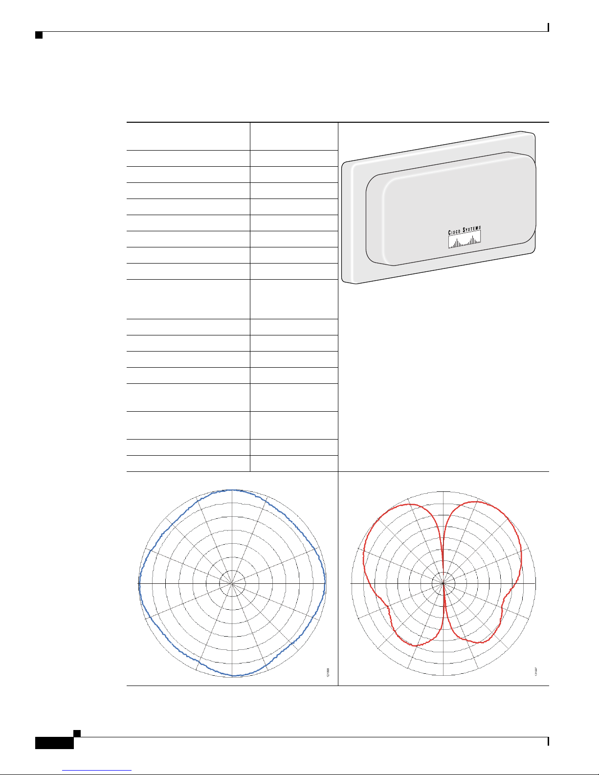
Technical Specifications
Technical Specifications
Antenna type Omnidirectional
Operating frequency range 5150 – 5850 MHz
Nominal input impedance 50Ω
2:1 VSWR bandwidth 5000 – 6000 MHz
Gain 4.5 dBi
Polarization Linear
Front-to-back ratio 10 dB
E-plane 3dB beamwidth 50°
H-plane 3dB beamwidth Omnidirectional
Cable length and type 36 in. (91.4 cm)
Connector type 2 RP-TNC Male
Length 5 in. (12.7 cm)
Width 3 in. (7.6 cm)
Height 0.75 oz (21.2 g)
Operating temperature –22°F – 158°F
Storage temperature –40°F – 185°F
UL2043 compliant Yes
Environment Indoor, office
H-Plane Pattern E-Plane Pattern
TM02 Mode Patch
121666
Plenum rated UV
stable LMR-185
(–30°C – 70°C)
(–40°C – 85°C)
Cisco Aironet 4.5-dBi Low Profile Omnidirectional Antenna (AIR-ANT5145V-R)
2
78-16467-03
Page 3

System Requirements
This antenna is designed for use with Cisco Aironet access points and bridges but can be used with any
5-GHz Cisco Aironet radio device that utilizes reverse polarity Neil Councilman (RP-TNC) connectors.
Installation Guidelines
Because the antenna transmits and receives radio signals, they are susceptible to RF obstructions and
common sources of interference that can reduce throughput and range of the device to which they are
connected. Follow these guidelines to ensure the best possible performance:
• Mount the antenna to utilize its propagation characteristics. One way to do this is to orient the
antenna horizontally and mount it as high as possible.
• Keep the antenna away from metal obstructions such as heating and air-conditioning ducts, large
ceiling trusses, building superstructures, and major power cabling runs. If necessary, use a rigid
conduit to lower the antenna away from these obstructions.
• The density of the materials used in a building’s construction determines the number of walls the
signal must pass through and still maintain adequate coverage. Consider the following before
choosing the location to install your antenna:
–
Paper and vinyl walls have very little affect on signal penetration.
System Requirements
–
Solid and pre-cast concrete walls limit signal penetration to one or two walls without degrading
coverage.
–
Wood and concrete block walls limit signal penetration to three or four walls.
–
A signal can penetrate five or six walls constructed of drywall or wood.
–
A thick metal wall causes signals to reflect off, causing poor penetration.
Safety Instructions
Follow these safety precautions when installing your antenna.
• Plan your installation procedure carefully and completely before you begin.
• If you are installing an antenna for the first time, for your own safety as well as others, seek
professional assistance. Consult your dealer, who can explain which mounting method to use for
the location where you intend to install the antenna.
• Select your installation site with safety, as well as performance, in mind. Remember that electric
power lines and telephone lines look alike. For your safety, assume that any line is an electric power
line until determined otherwise.
• Call your local power company or building maintenance organization if you are unsure about cables
close to your intended mounting location.
• If an accident or emergency occurs with the power lines, call for qualified emergency help
immediately.
• When installing your antenna in any location, do not use a metal ladder. Do dress properly - shoes
with rubber soles and heels, rubber gloves, and a long sleeved shirt or jacket. When drilling
mounting holes, wear safety glasses.
78-16467-03
Cisco Aironet 4.5-dBi Low Profile Omnidirectional Antenna (AIR-ANT5145V-R)
3
Page 4

Installing the Antenna
Installing the Antenna
The antenna ships with a mounting bracket and the hardware required to install the antenna on a
suspended ceiling. Two mounting methods are available. You can mount the antenna using standard
suspended ceiling T-rail clips or you can mount the antenna using the clips attached to the antenna
mounting bracket. Figure 1 shows the layout of the detachable mounting bracket configured to use the
suspended ceiling T-rail clips.
Figure 1 Mounting Bracket Configured to Use Suspended Ceiling T-rail Clips
1
1
2
3
1
2
121664
1 Retaining tabs 3 Mounting bracket
2 T-rail clip fastener
Figure 2 shows how the antenna mounting bracket is attached to a suspend ceiling T-rail using the
attached clips.
Figure 2 Antenna Mounting Bracket Attached Mounting Clip Location
Cisco Aironet 4.5-dBi Low Profile Omnidirectional Antenna (AIR-ANT5145V-R)
4
146340
78-16467-03
Page 5

Tools and Equipment Required
To install the antenna, you will need the following tools and equipment.
• The mounting kit supplied with your antenna consisting of:
–
Mounting bracket
–
Two T-rail clips with studs
–
Two plastic spacers
–
Two 1/4-20 T-rail nuts with built-in washers
• A 9 mm open end wrench or suitable pliers
• Standard screwdriver
• A 3/4 in. (20 mm) drill bit
• A Drill
• A pencil or suitable marker
Installing the Antenna Using T-Rail Clips
Installing the Antenna
Follow these steps to install the antenna using the T-rail clips. It may be helpful to refer to before you
begin.
Step 1 Choose a location in which to install the antenna.
Step 2 Remove the adjacent ceiling panels on each side of the T-rail on which the antenna is to be installed.
Note The panels must be removed so you can attach the antenna’s cables to the cables coming from
the device using the antenna. Removing the pane lets you support to the ceiling T-rail when you
snap the antenna in place on the mounting bracket.
Step 3 Attach the T-rail clips to the ceiling T-rail.
Step 4 Verify that the distance between the t-rail studs is 3.125-in (80 mm).
Step 5 Use a screwdriver to tighten the T-rail clip stud to the T-rail.
Step 6 Slip a plastic spacer onto the stud of each T-rail clip. Make sure the spacer legs are positioned against
the T-rail. See Figure 1 for details.
Step 7 Position the mounting bracket into the T-rail clip studs.
Step 8 Start a T-rail nut on each stud.
Step 9 Tighten each T-rail nut wrench tight.
Step 10 Use the mounting bracket to determine and mark where to drill the antenna cable access hole in the
ceiling panel.
Step 11 Drill a 3/4 in. (20 mm) hole at each mark.
Step 12 Position the antenna over the mounting bracket and feed each cable through its respective access hole.
Step 13 Grasp the ceiling T-rail as closely as possible to the mounting bracket while aligning the antenna with
the retaining tabs.
Step 14 Snap the antenna over the retaining tabs.
78-16467-03
Cisco Aironet 4.5-dBi Low Profile Omnidirectional Antenna (AIR-ANT5145V-R)
5
Page 6

Installing the Antenna
Step 15 Connect the antenna cables.
Step 16 Replace the ceiling panels.
Figure 3 T-rail Clip Installation Details
5
3
3
6
2
1
1 Antenna 4 Antenna cable
2 Mounting bracket 5 T-rail clip
3 Antenna connectors 6 Ceiling T-rail
Installing the Antenna Using Attached Mounting Clips
Follow these steps to install the antenna on a suspended ceiling using the mounting clips attached to the
antenna mounting bracket.
Note You cannot mount the antenna on suspended ceiling having recessed tiles. The clips are designed to be
used on a ceiling having flush mounted tiles.
Step 1 If the T-rail clips are fastened to the antenna mounting bracket, remove them.
4 4
121665
Step 2 Choose a location in which to install the antenna.
Step 3 Remove the adjacent ceiling panels on each side of the T-rail on which the antenna is to be installed.
Cisco Aironet 4.5-dBi Low Profile Omnidirectional Antenna (AIR-ANT5145V-R)
6
78-16467-03
Page 7

Installing the Antenna
Note The panels must be removed so you can attach the antenna’s cables to the cables coming from
the device using the antenna. Removing the pane lets you support to the ceiling T-rail when you
snap the antenna in place on the mounting bracket.
Step 4 Snap the antenna over the retaining tabs on the mounting bracket
Step 5 Align the mounting clips with the edge of the ceiling T-rail where you want to mount the antenna.
Step 6 Grasp the ceiling T-rail as closely as possible to the mounting bracket while pushing the clips securely
onto the rail.
Step 7 Connect the antenna cables.
Step 8 Replace the ceiling panels.
Figure 4 Attached Clip Mounting Details
5
1 Antenna 4 Mounting clips
2 Mounting bracket 5 Ceiling T-rail
3 Antenna connectors
78-16467-03
146342
1 24 43 3
Cisco Aironet 4.5-dBi Low Profile Omnidirectional Antenna (AIR-ANT5145V-R)
7
Page 8

Suggested Cable
Cisco recommends a high-quality, low-loss cable for use with the antenna.
Note Coaxial cable loses efficiency as the frequency increases, resulting in signal loss. The cable
should be kept as short as possible because cable length also determines the amount of
signal loss (the longer the run, the greater the loss).
The antenna terminates with a RP-TNC plug after a short, 3-ft (0.91-m) cable. The mating connector to
the antenna is an appropriate RP-TNC jack.
Obtaining Documentation and Submitting a Service Request
For information on obtaining documentation, submitting a service request, and gathering additional
information, see the monthly What’s New in Cisco Product Documentation, which also lists all new and
revised Cisco technical documentation, at:
http://www.cisco.com/en/US/docs/general/whatsnew/whatsnew.html
Subscribe to the What’s New in Cisco Product Documentation as a Really Simple Syndication (RSS) feed
and set content to be delivered directly to your desktop using a reader application. The RSS feeds are a free
service and Cisco currently supports RSS Version 2.0.
Cisco and the Cisco Logo are trademarks of Cisco Systems, Inc. and/or its affiliates in the U.S. and other countries. A listing of Cisco's trademarks
can be found at www.cisco.com/go/trademarks. Third party trademarks mentioned are the property of their respective owners. The use of the word
partner does not imply a partnership relationship between Cisco and any other company. (1005R)
Cisco Aironet 4.5-dBi Low Profile Omnidirectional Antenna (AIR-ANT5145V-R)
8
78-16467-03
 Loading...