

Page 1
Cisco Aironet Omnidirectional Mast Mount
Antenna (AIR-ANT2506)
This document outlines the specifications, describes the omnidirectional mast mount antenna, and
provides instructions for mounting it. Designed for WLAN applications in the 2.4- to 2.5-GHz frequency
range, the antenna has a nominal gain of 5.2 dBi and is typically mounted indoors or outdoors on a mast.
The antenna is compatible with Cisco Aironet radio products utilizing a reverse polarity TNC (RP-TNC)
connector.
The following information is provided in this document.
• Technical Specifications, page 2
• System Requirements, page 2
• Installation Notes, page 3
• Safety Precautions, page 7
• Obtaining Documentation and Submitting a Service Request, page 8
Americas Headquarters:
Cisco Systems, Inc., 170 West Tasman Drive, San Jose, CA 95134-1706 USA
Page 2
Technical Specifications
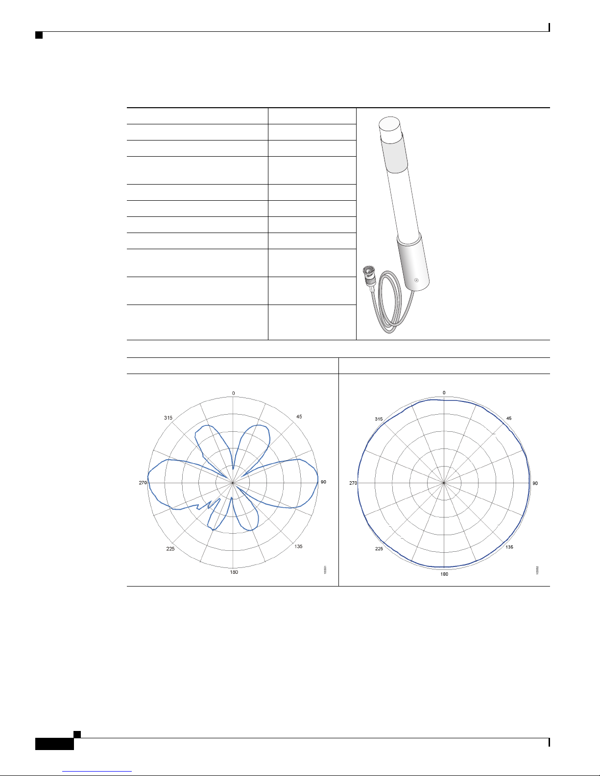
Technical Specifications
Antenna type Dipole
Operating frequency range 2.4- to 2.84-GHz
Environment Indoor/outdoor
VSWR Less than 2:1, 1.5:1
Gain 5.2 dBi
Polarization Linear, vertical
E-Plane (3dB bandwidth) 36 degrees
H-Plane (3dB bandwidth) Omnidirectional
Cable length and type 3 ft. (0.91 m)
Dimensions (H x W) 11.5 in x 1.125 in.
Mounting Mast, 2 in (5.08 cm)
nominal
RG-58
(29.2 cm x 2.8 cm)
maximum
81017
E-Plane Pattern H-Plane Pattern
System Requirements
This antenna is compatible with any 2.4-GHz Cisco Aironet radio device with an RP-TNC connector.
Cisco Aironet Omnidirectional Mast Mount Antenna (AIR-ANT2506)
2
78-14722-03
Page 3
Installation Notes
General Installation Instructions for Mast Mounted Antennas
Caution For outside installations, make sure you do not mount the antenna upside down or block the bottom of
the antenna at the cable exit. The correct mounting position is with the cable pointing down (towards the
ground) so that any moisture will drain through the antenna drain holes. The antenna ships with a yellow
mounting instruction label temporarily attached to the antenna radome.
The following instructions are common to most mast mounted installations.
1. Assemble your new antenna on the ground at the installation site.
2. Attach the antenna to the mast and connect its coaxial cable while you are on the ground.
3. Make sure the mast doesn’t fall the “wrong way” should you lose control as you raise or take down
the mast. Use a durable non-conductive rope secured at each two foot level as the mast is raised.
Have an assistant tend the rope, ready to pull the mast clear of any hazards (such as power lines)
should it begin to fall.
4. Use the mounting bracket provided with the antenna.
5. If the installation will use guy wires:
Installation Notes
a. Install guy anchor bolts.
b. Estimate the length of guy wire and cut it before raising the mast.
c. Attach guy wires to a mast using guy rings.
6. Carefully connect the antenna and mast assembly to its mounting bracket and tighten the clamp
bolts.
a. In the case of a a guyed installation, you must have at least one assistant to hold the mast upright
while the guy wires are attached and tightened to the anchor bolts.
7. Attach the provided self-adhering “DANGER” label at eye level on the mast.
8. Install ground rods to remove any static electricity buildup and connect a ground wire to the mast
and ground rod. Use ground rods designed for that purpose, not a spare piece of pipe.
Grounding the Antenna
Follow these guidelines to ground the antenna in accordance with national electrical code instructions.
1. Use No. 10 AWG copper or No. 8 or larger copper-clad steel or bronze wire as ground wires for both
mast and lead-in. Securely clamp the wire to the bottom of the mast.
2. Secure the lead-in wire to a lightning arrestor and mast ground wire to the building with stand-off
insulators spaced from 4 feet (1.2 meters) to 8 feet (1.8 meters) apart.
3. Mount the lightning arrestor as close as possible to where the lead-in wire enters the building.
4. Drill a hole in the building’s wall as close as possible to the equipment to which you will connect
the lead-in cable.
78-14722-03
Cisco Aironet Omnidirectional Mast Mount Antenna (AIR-ANT2506)
3
Page 4

Installation Notes
Caution There may be wires in the wall. Make sure you determine the place you intend to drill the hole is clear
of any any obstructions or other hazards.
5. Pull the cable through the hole and form a drip loop close to where it enters the building.
6. Thoroughly waterproof the lead-in area.
7. Install a static electricity discharge unit.
8. Connect the lead-in cable to the equipment.
Choosing a Mounting Location
The location of the antenna is important. Objects such as metal columns, walls, etc. will reduce
efficiency. Best performance is achieved when transmit and receive antennas are mounted at the same
height and in a direct line of sight with no obstructions. If this is not possible and reception is poor, you
should try different mounting positions to optimize reception.
The antenna is designed to create an omni-directional broadcast pattern. To achieve this pattern, the
antenna should be mounted clear of any obstructions to the sides of the radiating element. If the
mounting location is on the side of a building or tower, the antenna pattern will be degraded on the
building or tower side.
Site Selection
Before attempting to install your antenna, think where you can best place the antenna for safety and
performance.
Follow these steps to determine a safe distance from wires, power lines, and trees.
Step 1 Measure the height of your antenna.
Step 2 Add this length to the length of your tower or mast and then double this total for the minimum
recommended safe distance.
Caution If you are unable to maintain this safe distance, stop and get professional help.
Generally, the higher your antenna is above the ground, the better it performs. Good practice is to install
your antenna about 5 to 10 feet (1.5 to 3 meters) above the roof line and away from all power lines and
obstructions. If possible, find a mounting place directly above your wireless device so that the lead-in
cable can be as direct as possible.
Tools and Equipment Required
To install the antenna, you will need the following tools and equipment.
• A standard screwdriver
• A standard hose clamp (shipped with your antenna)
Cisco Aironet Omnidirectional Mast Mount Antenna (AIR-ANT2506)
4
78-14722-03
Page 5

Note This list does not include the tools and equipment required to assemble and erect the tower, mast, or other
structure you intend to mount your antenna on.
The following sections contain procedures for installing the antenna. Choose the procedure that applies
to your situation. Use figure 1 as a guide.
Mounting the Antenna
The antenna is provided with a mounting kit consisting of a mounting bracket and hose clamp. This kit
allows you to mount the antenna to masts from 1.25 inches (3.2 centimeters) to 2 inches (5.1
centimeters). Cisco recommends that a 1.5 inch (3.8 centimeter) or larger tubing mast be used.
The antenna is vertically polarized. Since the antenna has vertical gain, it is very important to mount the
antenna in a vertical (not leaning) position for optimal performance.
Follow these steps to mount the antenna on a mast.
Step 1 Position the antenna, mounting bracket, and hose clamp on the mast as shown in figure 1.
Installation Notes
Figure 1 Antenna Mounting Details
1
2
3
4
1 Antenna 2 Mounting bracket
3 Hose clamp 4 Mast
78-14722-03
74964
Cisco Aironet Omnidirectional Mast Mount Antenna (AIR-ANT2506)
5
Page 6

Installation Notes
Caution For outside installations, make sure you do not mount the antenna upside down or block the bottom of
the antenna at the cable exit. The correct mounting position is with the cable pointing down (towards the
ground) so that any moisture will drain through the antenna drain ring. The antenna ships with a yellow
mounting instruction label temporarily attached to the antenna radome.
Figure 2 Antenna Drain Details
1
2
271162
1 Drain ring 2 Antenna cable
Step 2
Step 3 Tighten the hose clamp until the antenna is secure on the mast.
Step 4 Connect the antenna coaxial cable to the lead-in cable.
Step 5 Remove the yellow mounting instruction label.
Step 6 If the installation is outdoors, weatherproof the antenna connection (the point at which the antenna cable
Align the antenna so that the metal base is even with or above the top of the mast tubing.
connects to another cable or device).
Note The antenna is not DC grounded. It is recommended that you install lightning-protection
devices in your system. See Installation Instructions for Cisco Aironet Lightning Arrestors.
This document is available on the World Wide Web at the following URL:
http://www.cisco.com/en/US/docs/wireless/lightning_arrestor/installation/guide/hslar.htm
l
Suggested Cable
Cisco recommends a high-quality, low-loss cable for use with the antenna.
Note The higher the frequency, the higher the loss through the cable. Also, the longer the run,
the higher the loss.
Cisco Aironet Omnidirectional Mast Mount Antenna (AIR-ANT2506)
6
78-14722-03
Page 7

The antenna terminates with a special connector (reverse-TNC plug) after a short, 3-ft. (91.4 cm) cable.
The mating connector to the antenna is an appropriate reverse-TNC jack connector. The connector on
the opposite end will vary according to the type of equipment used.
After the cable is attached to the antenna, make sure that the connections are sealed (if using outdoors)
to prevent moisture and other weathering elements from affecting performance.
Note The bottom of the antenna at the base (where the cable exits the antenna) should
not be covered. The drain ring allows the antenna to vent any internal condensation.
Cisco recommends using a coax seal (such as CoaxSeal) for outdoor connections. Silicon sealant or
electrical tape are not recommended for sealing outdoor connections.
Safety Precautions
Safety Precautions
Warning
Installation of this antenna near power lines is dangerous. For your safety, follow the installation
directions.
Each year hundreds of people are killed or injured when attempting to install an antenna. In many of
these cases, the victim was aware of the danger of electrocution, but did not take adequate steps to avoid
the hazard.
For your safety, and to help you achieve a good installation, please read and follow these safety
precautions. They may save your life!
1. If you are installing an antenna for the first time, for your own safety as well as others, seek
professional assistance. Your Cisco sales representative can explain which mounting method to use
for the size and type antenna you are about to install.
2. Select your installation site with safety, as well as performance in mind. Remember: electric power
lines and phone lines look alike. For your safety, assume that any overhead line can kill you.
3. Call your electric power company. Tell them your plans and ask them to come look at your proposed
installation. This is a small inconvenience considering your life is at stake.
4. Plan your installation carefully and completely before you begin. Successful raising of a mast or
tower is largely a matter of coordination. Each person should be assigned to a specific task, and
should know what to do and when to do it. One person should be in charge of the operation to issue
instructions and watch for signs of trouble.
5. When installing your antenna, remember:
a. Do not use a metal ladder.
b. Do not work on a wet or windy day.
c. Do dress properly—shoes with rubber soles and heels, rubber gloves, long sleeved shirt or
jacket.
6. If the assembly starts to drop, get away from it and let it fall. Remember, the antenna, mast, cable,
and metal guy wires are all excellent conductors of electrical current. Even the slightest touch of any
of these parts to a power line complete an electrical path through the antenna and the installer: you!
78-14722-03
Cisco Aironet Omnidirectional Mast Mount Antenna (AIR-ANT2506)
7
Page 8

Safety Precautions
7. If any part of the antenna system should come in contact with a power line, don’t touch it or try to
remove it yourself. Call your local power company. They will remove it safely.
8. If an accident should occur with the power lines call for qualified emergency help immediately.
Obtaining Documentation and Submitting a Service Request
For information on obtaining documentation, submitting a service request, and gathering additional
information, see the monthly What’s New in Cisco Product Documentation, which also lists all new and
revised Cisco technical documentation, at:
http://www.cisco.com/en/US/docs/general/whatsnew/whatsnew.html
Subscribe to the What’s New in Cisco Product Documentation as a Really Simple Syndication (RSS) feed
and set content to be delivered directly to your desktop using a reader application. The RSS feeds are a free
service and Cisco currently supports RSS Version 2.0.
Cisco and the Cisco Logo are trademarks of Cisco Systems, Inc. and/or its affiliates in the U.S. and other countries. A listing of Cisco's trademarks
can be found at www.cisco.com/go/trademarks. Third party trademarks mentioned are the property of their respective owners. The use of the word
partner does not imply a partnership relationship between Cisco and any other company. (1005R)
Cisco Aironet Omnidirectional Mast Mount Antenna (AIR-ANT2506)
8
78-14722-03
 Loading...