

Page 1

Overview
Cisco Aironet 13.5-dBi Yagi Mast Mount Antenna
(AIR-ANT1949)
This document describes the 13.5-dBi Yagi mast mount antenna and provides instructions for mounting
it. The antenna operates in the 2.4- to 2.5-GHz frequency range and is designed for point-to-point
communications. The antenna is a completely enclosed 16-element, vertically polarized directional Yagi
and is designed to be mounted outdoors on a mast. The antenna can also be used indoors and can be
mounted on a flat vertical surface, such as a wall.
The following information is provided in this document.
• Technical Specifications, page 2
• System Requirements, page 2
• Installation Notes, page 4
• Choosing a Mounting Location, page 5
• Tools and Equipment Required, page 5
• Mounting the Antenna, page 6
• Obtaining Documentation and Submitting a Service Request, page 8
Corporate Headquarters:
Cisco Systems, Inc., 170 West Tasman Drive, San Jose, CA 95134-1706 USA
© 2006 Cisco Systems, Inc. All rights reserved.
Page 2
Technical Specifications
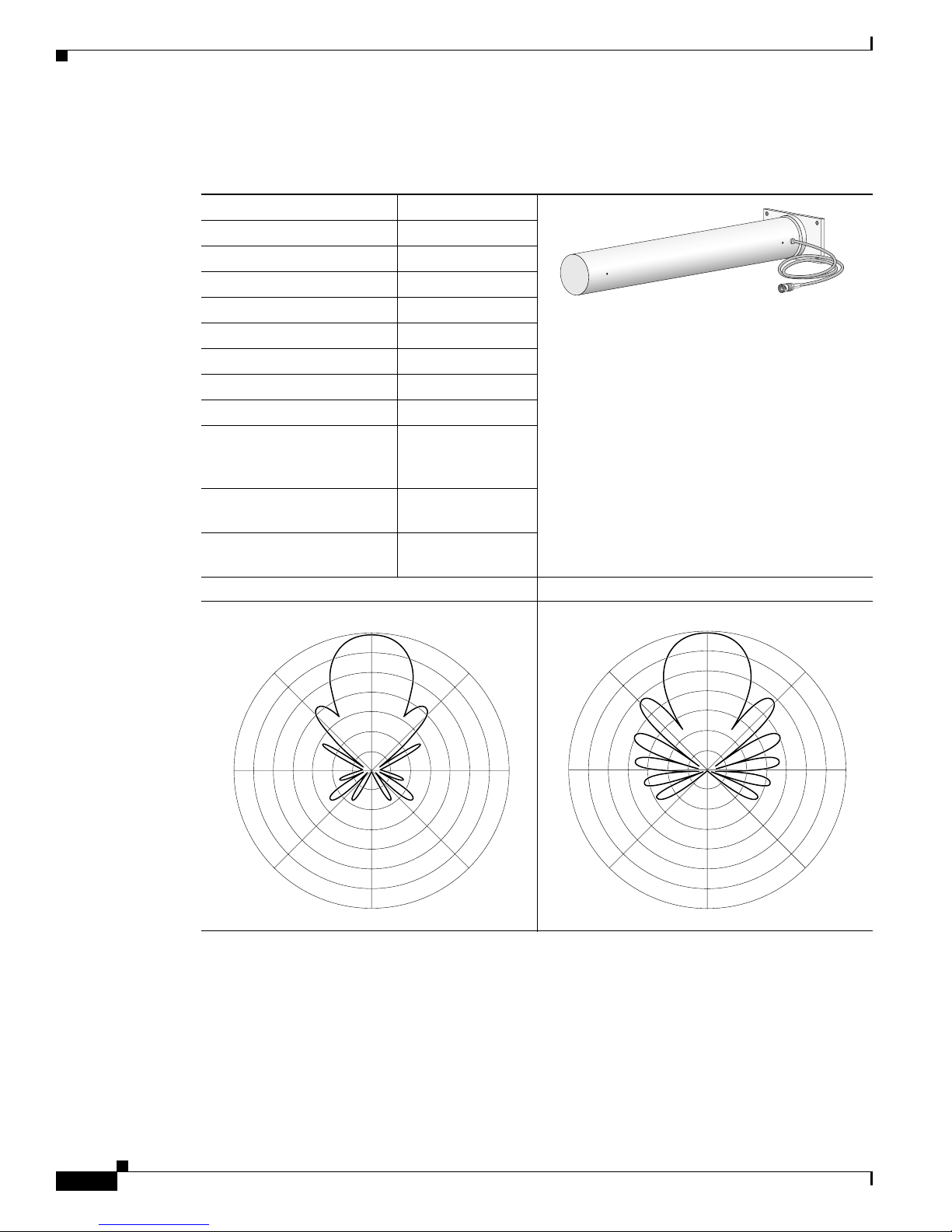
Technical Specifications
Antenna type Yagi
Operating frequency range 2400 – 2484 MHz
Nominal input impedence 50Ω
1.5:1 VSWR bandwidth 2400 – 2485 MHz
Environment Outdoor/indoor
Gain 13.5 dBi
Polarization Vertical
H-Plane (3dB bandwidth) 30°
V-Plane (3dB bandwidth) 30°
Cable length and type 3 ft. (0.91 m)
Dimensions (H x W) 16.5 in. x 3 in.
Wind rating 125 MPH
Azimuth Radiation Pattern Elevation Radiation Pattern
81016
Plenum rated
RG-58
(41.9 cm x 7.6 cm)
(201.2 KMH)
315
225
System Requirements
This antenna is designed for use with Cisco Aironet access points and bridges but can be used with any
2.4-GHz Cisco Aironet radio device that uses a reverse-polarity threaded naval connector (RP-TNC).
180
180
0
45
90270
135
81012
0
45
90270
135
81011
315
225
Cisco Aironet 13.5-dBi Yagi Mast Mount Antenna (AIR-ANT1949)
2
78-14720-02
Page 3
Safety Precautions
Safety Precautions
Warning
Warning
IMPORTANT SAFETY INSTRUCTIONS
This warning symbol means danger. You are in a situation that could cause bodily injury. Before you
work on any equipment, be aware of the hazards involved with electrical circuitry and be familiar
with standard practices for preventing accidents. Use the statement number provided at the end of
each warning to locate its translation in the translated safety warnings that accompanied this
device.
SAVE THESE INSTRUCTIONS
In order to comply with FCC radio frequency (RF) exposure limits, antennas should be located at a
minimum of 7.9 inches (20 cm) or more from the body of all persons.
Statement 1071
Statement 332
Each year hundreds of people are killed or injured when attempting to install an antenna. In many of
these cases, the victim was aware of the danger of electrocution, but did not take adequate steps to avoid
the hazard.
For your safety, and to help you achieve a good installation, please read and follow these safety
precautions. They may save your life!
1. If you are installing an antenna for the first time, for your own safety as well as others, seek
professional assistance. Your Cisco sales representative can explain which mounting method to use
for the size and type antenna you are about to install.
2. Select your installation site with safety, as well as performance in mind. Remember: electric power
lines and phone lines look alike. For your safety, assume that any overhead line can kill you.
3. Call your electric power company. Tell them your plans and ask them to come look at your proposed
installation. This is a small inconvenience considering your life is at stake.
4. Plan your installation carefully and completely before you begin. Successful raising of a mast or
tower is largely a matter of coordination. Each person should be assigned to a specific task, and
should know what to do and when to do it. One person should be in charge of the operation to issue
instructions and watch for signs of trouble.
5. When installing your antenna, remember:
a. Do not use a metal ladder.
b. Do not work on a wet or windy day.
c. Do dress properly—shoes with rubber soles and heels, rubber gloves, long sleeved shirt or
jacket.
6. If the assembly starts to drop, get away from it and let it fall. Remember, the antenna, mast, cable,
and metal guy wires are all excellent conductors of electrical current. Even the slightest touch of any
of these parts to a power line complete an electrical path through the antenna and the installer: you!
78-14720-02
Cisco Aironet 13.5-dBi Yagi Mast Mount Antenna (AIR-ANT1949)
3
Page 4

Installation Notes
7. If any part of the antenna system should come in contact with a power line, don’t touch it or try to
remove it yourself. Call your local power company. They will remove it safely.
8. If an accident should occur with the power lines call for qualified emergency help immediately.
Installation Notes
General Installation Instructions for Mast-Mounted Antennas
The following instructions are common to most mast-mounted installations.
Step 1 Assemble your new antenna on the ground at the installation site.
Step 2 Attach the antenna to the mast and connect its coaxial cable while you are on the ground.
Step 3 If you lose control of the mast while raising it, make sure that it does not fall in the wrong direction. Use
a durable non-conductive rope secured at each 2-foot level as the mast is raised. Have an assistant tend
the rope, ready to pull the mast clear of any hazards (such as power lines) if it begins to fall.
Step 4 Use the mounting bracket provided with the antenna.
Step 5 If the installation will use guy wires:
a. Install guy anchor bolts.
b. Estimate the length of guy wire and cut it before raising the mast.
c. Attach guy wires to a mast using guy rings.
Step 6 Carefully connect the antenna and mast assembly to its mounting bracket and tighten the clamp bolts.
a. For a guyed installation, you must have at least one assistant to hold the mast upright while you
attach and tighten the guy wires to the anchor bolts.
Step 7 Attach the provided self-adhering DANGER label at eye level on the mast.
Step 8 Install ground rods to remove any static electricity buildup and connect a ground wire to the mast and
ground rod. Use ground rods designed for that purpose, not a spare piece of pipe.
Grounding the Antenna
Follow these guidelines to ground the antenna in accordance with national electrical code instructions.
1. Use No. 10 AWG copper or No. 8 or larger copper-clad steel or bronze wire as ground wires for both
mast and lead-in. Securely clamp the wire to the bottom of the mast.
2. Secure the lead-in wire to an antenna discharge unit and the mast ground wire to the building with
stand-off insulators spaced from 4 ft (1.2 m) to 8 ft (2.4 m) apart.
3. Mount the antenna discharge unit as closely as possible to where the lead-in wire enters the building.
4. Drill a hole in the building’s wall as closely as possible to the equipment to which you will connect
the lead-in cable.
Cisco Aironet 13.5-dBi Yagi Mast Mount Antenna (AIR-ANT1949)
4
78-14720-02
Page 5

Caution There may be wires in the wall. Make sure your drilling location is clear of any any obstructions or other
hazards.
5. Pull the cable through the hole and form a drip loop close to where it enters the building.
6. Thoroughly waterproof the lead-in area.
7. Install a lightning arrestor.
8. Connect the lead-in cable to the equipment.
Choosing a Mounting Location
The antenna is designed to create a directional broadcast pattern. To achieve this pattern, the antenna
should be mounted clear of any obstructions to the sides of the radiating element. If the mounting
location is on the side of a building or tower, the antenna pattern is degraded on the building or tower
side.
Site Selection
Installation Notes
Before attempting to install your antenna, determine where you can best place the antenna for safety and
performance.
Follow these steps to determine a safe distance from wires, power lines, and trees.
Step 1 Measure the height of your antenna.
Step 2 Add this length to the length of your tower or mast and then double this total for the minimum
recommended safe distance.
Caution If you are unable to maintain this safe distance, stop and get professional help.
Generally, the higher an antenna is above the ground, the better it performs. Good practice is to install
your antenna about 5 to 10 ft (1.5 to 3 m) above the roof line and away from all power lines and
obstructions. If possible, find a mounting place directly above your wireless device so that the lead-in
cable can be as direct as possible.
Tools and Equipment Required
A mast mounting installation kit is shipped with the antenna. To install the antenna on a mast, you need
the following tools and equipment.
• A 7/16-in. (11.1 mm) wrench
• Cable ties or electrical tape
• Coaxial cable weatherproofing material (such as CoaxSeal)
78-14720-02
Cisco Aironet 13.5-dBi Yagi Mast Mount Antenna (AIR-ANT1949)
5
Page 6

Installation Notes
Note The antenna can also be mounted on a wall or other flat vertical surface. Mounting hardware is not
provided.
The following sections contain a typical procedure for installing the antenna on a mast. Your installation
may vary. Before you begin, you may want to refer to Figure 1.
Mounting the Antenna
The antenna is provided with a mast mounting kit that allows you to mount the antenna to masts up to
1 5/8 in. in diameter. Figure 1 shows how the antenna should be mounted to a mast or wall.
Figure 1 Antenna Mounting
Backing
plate
Mast mount - side view
Backing
plate
Place flat washers between bolt heads
(or nuts) and mounting base in all
mounting configurations.
Intermediate plate required for
mounting on rough surfaces.
Direction of
maximum signal
Mast mount - top view
Direction of
maximum signal
Wall mount
81013
Cisco Aironet 13.5-dBi Yagi Mast Mount Antenna (AIR-ANT1949)
6
78-14720-02
Page 7

Installation Notes
Follow these instructions to mount the antenna on a mast.
Step 1 Attach the U-bolts, clamps, and backing plate to the antenna as shown in Figure 1.
Step 2 Install a washer and start a locknut on each U-bolt.
Step 3 Position the loose mounting assembly over the mast.
Note To ensure correct antenna polarization orientation, make sure the arrows on the antenna are
pointed up.
Step 4 Use a 7/16-in (11.1-mm) wrench or suitable adjustable wrench to secure the assembly to the mast.
Tighten the locknuts to a point where the antenna does not slide down the mast but is loose enough for
you to rotate.
Step 5 Rotate the antenna until it points towards the other WLAN antenna your wireless device is to
communicate with.
Note The accuracy of the orientation should be within 15 degrees to achieve maximum gain. This is
especially important if the path length is over 1 mile (1.6 kilometers). If you use this antenna to
connect to several terminals, aim it in the general direction of the group. If the paths are not
obstructed or are less than 1 mile (1.6 kilometers), this arrangement should work well.
Step 6 Tighten the locknuts.
Note Tighten the locknuts evenly and do not exceed 45 in-lbs of torque on the locknuts.
Step 7 Secure the antenna cable to the mast with cable ties or electrical tape.
Step 8 Apply the danger label to a plainly visible area of the antenna support structure.
Note The antenna is not DC grounded. It is recommended that you install lightning-protection
devices in your system. See the Installation Instructions for Cisco Aironet Lightning
Arrestors. This document is available on the World Wide Web at the following URL:
http://www.cisco.com/en/US/docs/wireless/lightning_arrestor/installation/guide/hslar.htm
l
Suggested Cable
Cisco recommends a high-quality, low-loss cable for use with the antenna.
Note The higher the frequency, the greater the loss through the cable. Also, the longer the run,
the greater the loss.
The antenna terminates with a RP-TNC plug after a short, 3-ft (0.91-m) cable. The mating connector to
the antenna is an appropriate RP-TNC jack. The connector on the opposite end will vary according to
the type of equipment used.
78-14720-02
Cisco Aironet 13.5-dBi Yagi Mast Mount Antenna (AIR-ANT1949)
7
Page 8

After the cable is attached to the antenna, make sure that the connections are sealed (if outdoors) to
prevent moisture and other weathering elements from affecting performance. Cisco recommends using
a coax seal (such as CoaxSeal) for outdoor connections. Silicon sealant or electrical tape is not
recommended for sealing outdoor connections.
Obtaining Documentation and Submitting a Service Request
For information on obtaining documentation, submitting a service request, and gathering additional
information, see the monthly What’s New in Cisco Product Documentation, which also lists all new and
revised Cisco technical documentation, at:
http://www.cisco.com/en/US/docs/general/whatsnew/whatsnew.html
Subscribe to the What’s New in Cisco Product Documentation as a Really Simple Syndication (RSS) feed
and set content to be delivered directly to your desktop using a reader application. The RSS feeds are a free
service and Cisco currently supports RSS Version 2.0.
Cisco and the Cisco Logo are trademarks of Cisco Systems, Inc. and/or its affiliates in the U.S. and other countries. A listing of Cisco's trademarks
can be found at www.cisco.com/go/trademarks. Third party trademarks mentioned are the property of their respective owners. The use of the word
partner does not imply a partnership relationship between Cisco and any other company. (1005R)
Cisco Aironet 13.5-dBi Yagi Mast Mount Antenna (AIR-ANT1949)
8
78-14720-02
 Loading...