

Page 1

Cisco Aironet Series 2800/3800 Access Point Deployment Guide
First Published: 2016-05-11
Americas Headquarters
Cisco Systems, Inc.
170 West Tasman Drive
San Jose, CA 95134-1706
USA
http://www.cisco.com
Tel: 408 526-4000
800 553-NETS (6387)
Fax: 408 527-0883
Page 2

THE SPECIFICATIONS AND INFORMATION REGARDING THE PRODUCTS IN THIS MANUAL ARE SUBJECT TO CHANGE WITHOUT NOTICE. ALL STATEMENTS,
INFORMATION, AND RECOMMENDATIONS IN THIS MANUAL ARE BELIEVED TO BE ACCURATE BUT ARE PRESENTED WITHOUT WARRANTY OF ANY KIND,
EXPRESS OR IMPLIED. USERS MUST TAKE FULL RESPONSIBILITY FOR THEIR APPLICATION OF ANY PRODUCTS.
THE SOFTWARE LICENSE AND LIMITED WARRANTY FOR THE ACCOMPANYING PRODUCT ARE SET FORTH IN THE INFORMATION PACKET THAT SHIPPED WITH
THE PRODUCT AND ARE INCORPORATED HEREIN BY THIS REFERENCE. IF YOU ARE UNABLE TO LOCATE THE SOFTWARE LICENSE OR LIMITED WARRANTY,
CONTACT YOUR CISCO REPRESENTATIVE FOR A COPY.
The Cisco implementation of TCP header compression is an adaptation of a program developed by the University of California, Berkeley (UCB) as part of UCB's public domain version
of the UNIX operating system. All rights reserved. Copyright©1981, Regents of the University of California.
NOTWITHSTANDING ANY OTHER WARRANTY HEREIN, ALL DOCUMENT FILES AND SOFTWAREOF THESE SUPPLIERS ARE PROVIDED “AS IS" WITH ALL FAULTS.
CISCO AND THE ABOVE-NAMED SUPPLIERS DISCLAIM ALL WARRANTIES, EXPRESSED OR IMPLIED, INCLUDING, WITHOUT LIMITATION, THOSE OF
MERCHANTABILITY, FITNESS FOR A PARTICULAR PURPOSE AND NONINFRINGEMENT OR ARISING FROM A COURSE OF DEALING, USAGE, OR TRADE PRACTICE.
IN NO EVENT SHALL CISCO OR ITS SUPPLIERS BE LIABLE FOR ANY INDIRECT, SPECIAL, CONSEQUENTIAL, OR INCIDENTAL DAMAGES, INCLUDING, WITHOUT
LIMITATION, LOST PROFITS OR LOSS OR DAMAGE TO DATA ARISING OUT OF THE USE OR INABILITY TO USE THIS MANUAL, EVEN IF CISCO OR ITS SUPPLIERS
HAVE BEEN ADVISED OF THE POSSIBILITY OF SUCH DAMAGES.
Any Internet Protocol (IP) addresses and phone numbers used in this document are not intended to be actual addresses and phone numbers. Any examples, command display output, network
topology diagrams, and other figures included in the document are shown for illustrative purposes only. Any use of actual IP addresses or phone numbers in illustrative content is unintentional
and coincidental.
Cisco and the Cisco logo are trademarks or registered trademarks of Cisco and/or its affiliates in the U.S. and other countries. To view a list of Cisco trademarks, go to this URL: http://
www.cisco.com/go/trademarks. Third-party trademarks mentioned are the property of their respective owners. The use of the word partner does not imply a partnership
relationship between Cisco and any other company. (1110R)
©
2016 Cisco Systems, Inc. All rights reserved.
Page 3

CONTENTS
CHAPTER 1
CHAPTER 2
CHAPTER 3
Overview 1
Choosing the Right Access Point 3
Models 3
Part Numbers and Descriptions 4
Supported Code Versions Compatible with AP 2800 and AP 3800 5
Differences between the AP 2800 and AP 3800 Access Points 5
Feature Differences 8
Ports on the AP 2800 and AP 3800 9
Modularity and Smart Antenna Connector Ports 10
Physical Hardware and Mounting Options 13
Access Point Physical Hardware and Mounting Options 13
Channel Rail Adapters 14
Mounting an AP Directly into the Tile Using Optional AIR-AP-BRACKET-3 16
Using an In-tile Mount from Oberon Wireless 18
Wall-mounting the AP 18
Changing the Color of an AP 21
Clean Rooms (Healthcare) 22
Above the Ceiling Tiles 22
CHAPTER 4
Understanding Flexible Radio Assignment (software overview) 25
Understanding Flexible Radio Assignment (Software Overview) 25
Flexible Radio Architecture (FRA) System 26
CHAPTER 5
Client Roaming in a Micro and Macro Cell 27
Understanding Macro and Micro Cells 27
Client Roaming from a Macro to Micro Cell 29
Cisco Aironet Series 2800/3800 Access Point Deployment Guide
iii
Page 4

Contents
Client Roaming from a Micro to Macro Cell 29
Micro and Macro cells on “I” Series Access Points 30
RF Operations on “E/P” Series Access Points 33
CHAPTER 6
CHAPTER 7
CHAPTER 8
CHAPTER 9
CHAPTER 10
CHAPTER 11
CHAPTER 12
CHAPTER 13
Approved Antennas for Use with Access Points 2800 and 3800 39
AP 2800 and AP 3800 Powering Options 41
AP 3800 and Multigigabit Ethernet (mGig) 47
New–B Regulatory Domain for US Theater 51
Stadium and Harsh Environments 53
Areas with High Vibration 55
Related References 57
Previous Deployment Guides 57
Frequently Asked Questions (FAQ's) 59
Cisco Aironet Series 2800/3800 Access Point Deployment Guide
iv
Page 5

CHAPTER 1
Overview
This document covers the Cisco 2800/3800 Series Access Points theory of operation and installation as part
of a Cisco wireless LAN (WLAN) solution. Subjects related include:
Choosing the right access point, part numbers and descriptions
•
Supported code versions
•
Differences between AP 2800 and AP 3800
•
Physicals / Hardware details, mounting options, bracket choices
•
Third party mounting options including hospital and cleanroom environments
•
Understanding Flexible Radio Assignment (FRA) and architecture
•
Understanding Macro and Microcells
•
Looking at roaming between cells
•
Hardware differences in FRA between I, E and P versions
•
• Approved antennas and new FCC regulatory –B domain
AP 2800 and AP 3800 powering options and requirements
•
AP 3800 and Multigigabit Ethernet (mGig)
•
Cisco Aironet Series 2800/3800 Access Point Deployment Guide
1
Page 6

Overview
Cisco Aironet Series 2800/3800 Access Point Deployment Guide
2
Page 7

Models
CHAPTER 2
Choosing the Right Access Point
Models, page 3
•
Part Numbers and Descriptions , page 4
•
Supported Code Versions Compatible with AP 2800 and AP 3800 , page 5
•
Differences between the AP 2800 and AP 3800 Access Points, page 5
•
Feature Differences, page 8
•
Ports on the AP 2800 and AP 3800 , page 9
•
Modularity and Smart Antenna Connector Ports , page 10
•
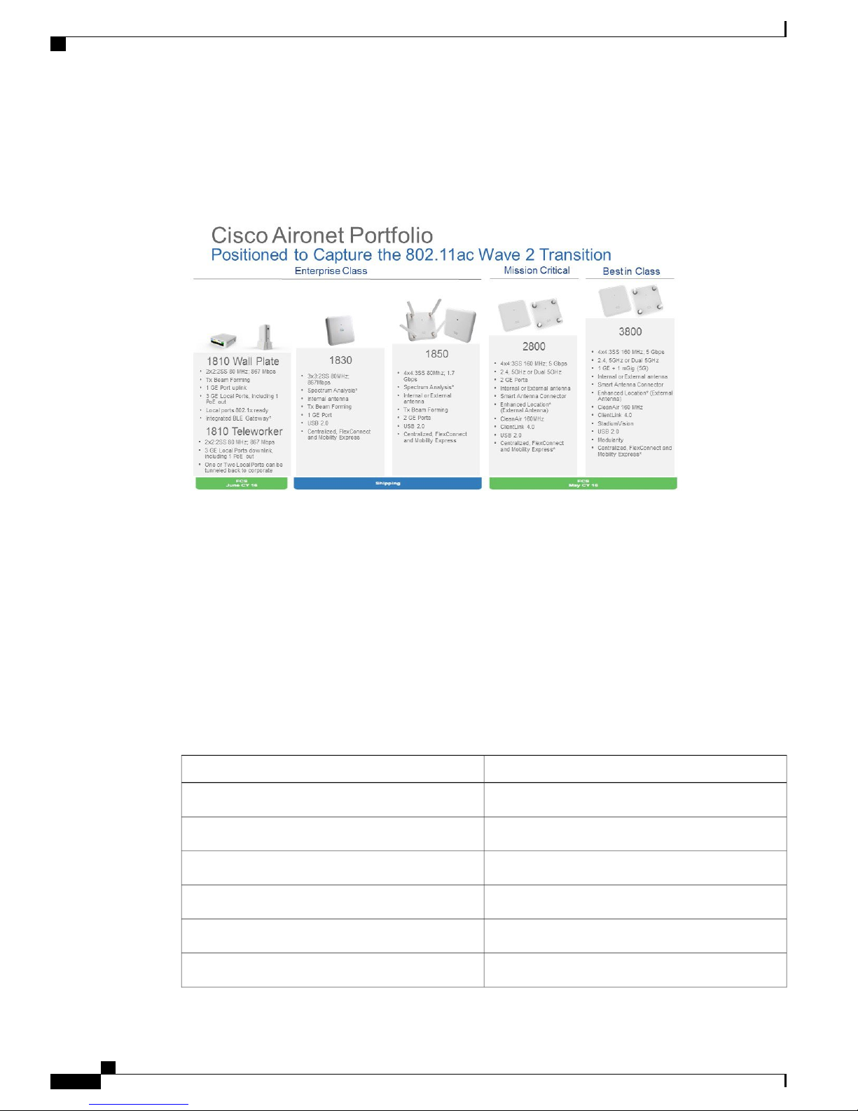
The Cisco 2800 and 3800 Series Access Points target customers requiring support for mission-critical and
best in class applications. The 2800/3800 embodies ClientLink 4.0, an innovative antenna technology comprising
four transmit radios and four receive radios called 4x4 in a Multiple Input Multiple Output (MIMO)
configuration and supporting three spatial streams (3SS), together referenced as 4x4:3. Using this type of
antenna system along with additional Modulation Coding Scheme (MCS) rates supporting up to 256 QAM
and up to 160 MHz channel bonding, rates of up to 5 Gbps can be supported.
Cisco Aironet Series 2800/3800 Access Point Deployment Guide
3
Page 8
Part Numbers and Descriptions
ClientLink 4.0 uses these features along with an additional antenna (N+1) to allow for beam-forming for all
802.11a/g/n/ac and now ac Wave-2 clients including those supporting 3 spatial streams.
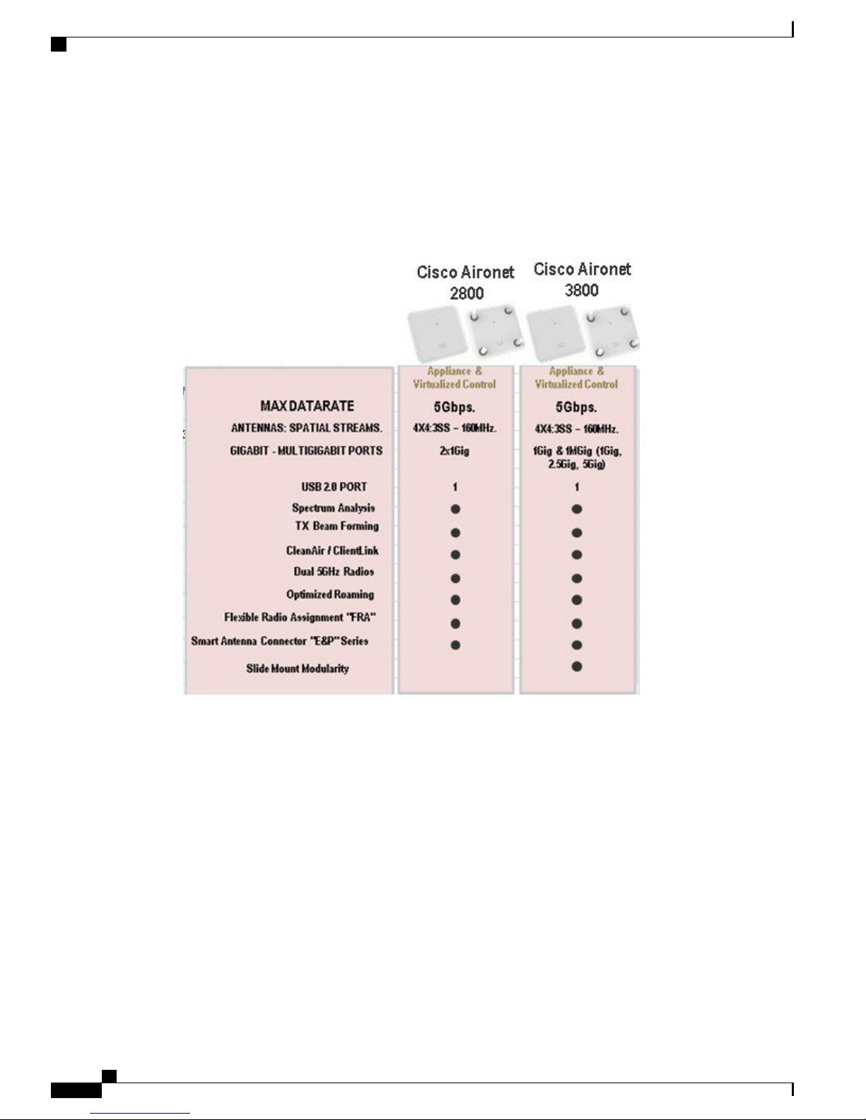
Figure 1: Access Point Portfolio Placement
Choosing the Right Access Point
Access points are available in three models:
• Internal antennas version labeled “i” that has captured antennas (part of the housing and not removable).
The “i” series is designed for indoor Enterprise installations where office aesthetics are a primary concern.
• External antennas version labeled “e” that is more rugged and designed for industrial use in locations
such as hospitals, factories, and warehouses, anywhere a need exists for external antennas and/or extended
operating temperatures. The “e” version also supports mounting inside NEMA enclosures for use in the
most demanding environments.
• Access points for professional install are labeled “p” series and may be used in outdoor applications.
Part Numbers and Descriptions
DescriptionSKU
Single Unit; Internal Antenna ModelAIR-AP3802I-x-K9
10 pack; Internal Antenna ModelAIR-AP3802I-xK910
Single Unit; External Antenna ModelAIR-AP3802E-x-K9
10 pack; External Antenna ModelAIR-AP3802E-xK910
Cisco Aironet Series 2800/3800 Access Point Deployment Guide
4
Single Unit; Internal Antenna Model; ConfigurableAIR-AP3802I-x-K9C
10 pack; Internal Antenna Model; ConfigurableAIR-AP3802I-xK910C
Page 9
Choosing the Right Access Point
Supported Code Versions Compatible with AP 2800 and AP 3800
DescriptionSKU
Single Unit; External Antenna Model; ConfigurableAIR-AP3802E-x-K9C
10 pack; External Antenna Model; ConfigurableAIR-AP3802E-xK910C
Supported Code Versions Compatible with AP 2800 and AP 3800
The minimum versions supporting the AP 2800 and 3800 are:
Wireless LAN Controller (WLC) AirOS release 8.2MR1
•
Polaris release 16.3
•
Prime release 3.1MR1
•
MSE or CMX 10.2.2
•
ISE 2.0
•
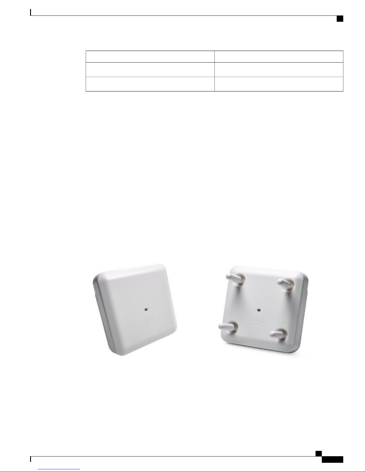
Differences between the AP 2800 and AP 3800 Access Points
The mechanical front of the AP 2800 and AP 3800 are nearly identical in physical appearance.
Figure 2: AP 2800 and AP 3800 (I and E) versions
Cisco Aironet Series 2800/3800 Access Point Deployment Guide
5
Page 10
Differences between the AP 2800 and AP 3800 Access Points
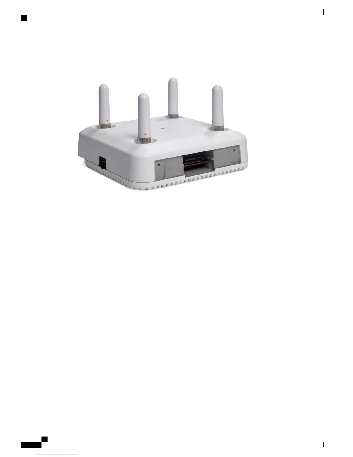
The AP 3800 is also available in a "P" version. The external antenna "E" versions permit antenna gains up to
6 dBi, "P" version up to 13 dBi.
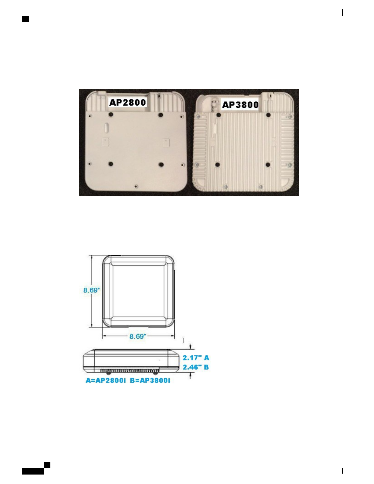
Figure 3: AP 2800/3800
Choosing the Right Access Point
There are slight differences in the weight and thickness of the 2800 and 3800. The AP 3800 is a bit more
robust as it has support for mGig (NBASE-T) and optional module support. AP 2800 on left is smooth and
does not have heat fins.
Figure 4: AP 2800/3800 Dimensions
Cisco Aironet Series 2800/3800 Access Point Deployment Guide
6
Page 11
Choosing the Right Access Point
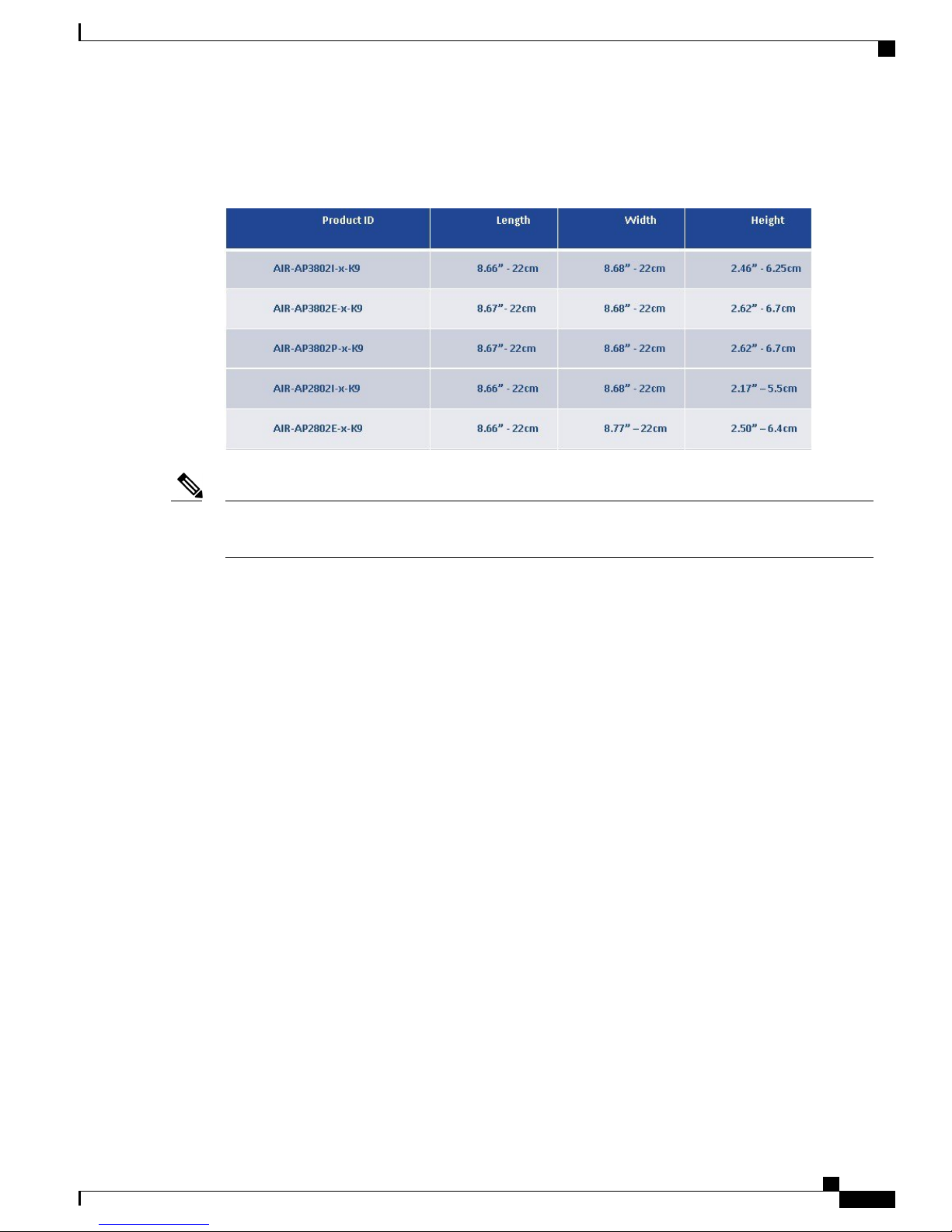
Depending on the model the thickness changes slightly.
Figure 5: AP 2800 and AP 3800 dimensions
Differences between the AP 2800 and AP 3800 Access Points
Note
The weight is slightly different between the models.AP 3800 both “E” and “P” versions as well as the
2800e is 2.1 kg.AP 3800i is 2.0 kg. AP 2800i is 1.6 kg.
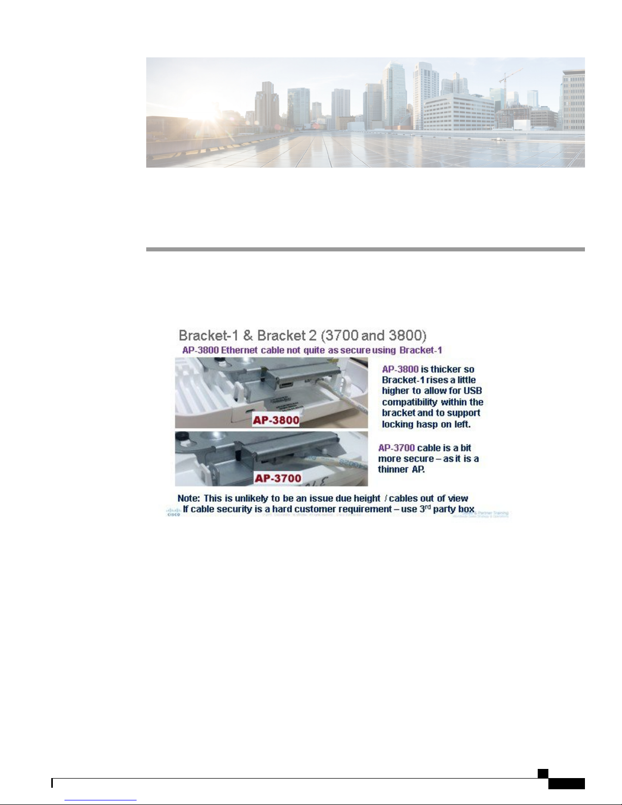
Both products use the same brackets as 2700/3700 2700/3700 Series Access Points–AIR-AP-BRACKET1
and AIR-AP-BRACKET-2.
Cisco Aironet Series 2800/3800 Access Point Deployment Guide
7
Page 12
Feature Differences
Feature Differences
Here is a basic feature comparison:
Figure 6: Feature comparisons of 2800 and 3800 series
Choosing the Right Access Point
Cisco Aironet Series 2800/3800 Access Point Deployment Guide
8
Page 13
Choosing the Right Access Point
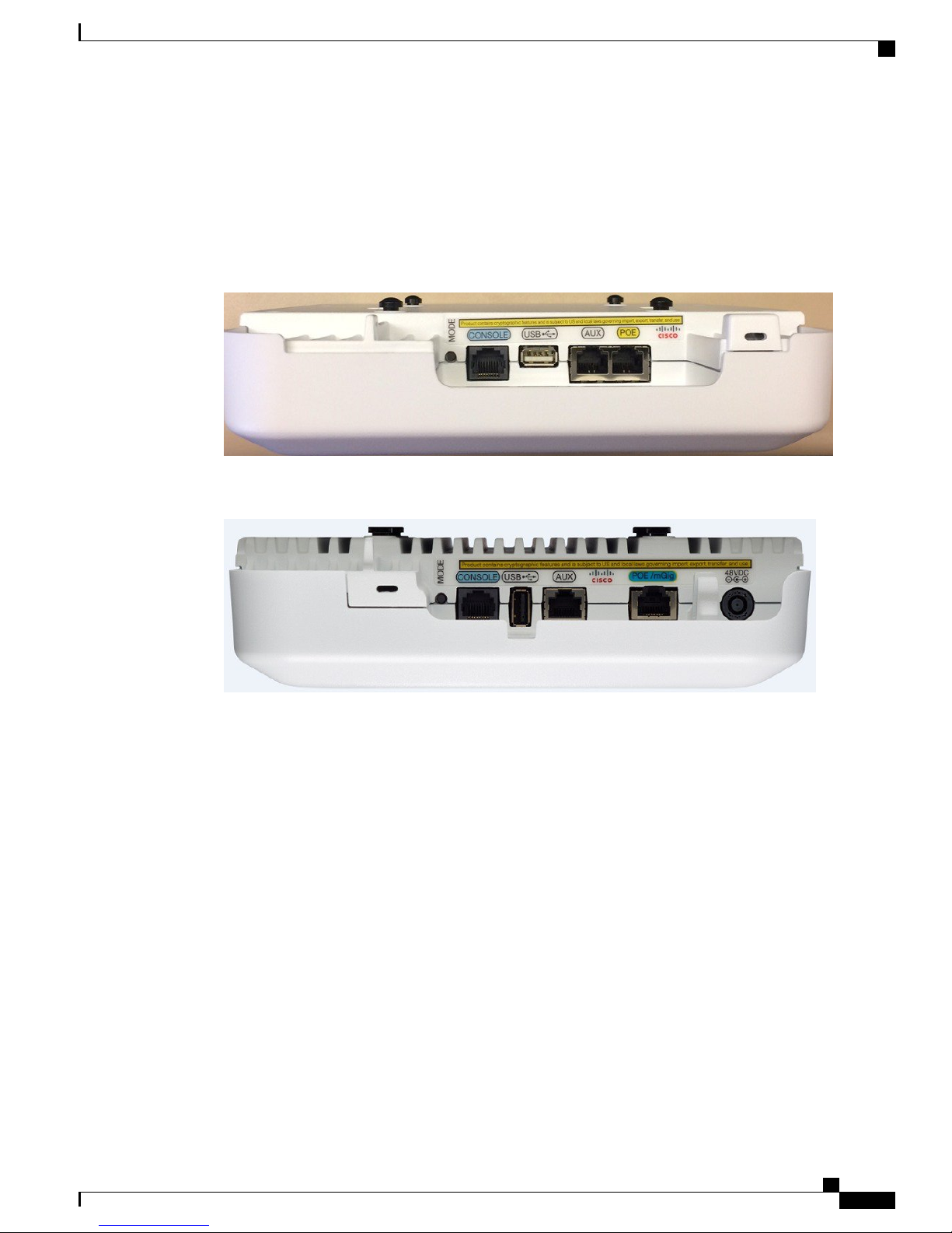
Ports on the AP 2800 and AP 3800
The AP 2800 is similar to the AP 3800 but lacks a local power supply input and mGig PoE port. Additionally,
the USB port is mounted sideways.
Figure 7: Ports on 2800 series
Ports on the AP 2800 and AP 3800
Figure 8: Ports on 3800 series
The AP 3800 has a local power supply jack on the right; This is a new style connector and is not compatible
with the older AIR-PWR-B power supplies used with the AP 2700 and AP 3700 series. For more on this
connector, see the AP 2800 and AP 3800 Powering Options for details.
Cisco Aironet Series 2800/3800 Access Point Deployment Guide
9
Page 14
Modularity and Smart Antenna Connector Ports
In addition there is an mGig port as well as a port for external modules on the AP 3800.
Figure 9: External module port on the 3800 series
Choosing the Right Access Point
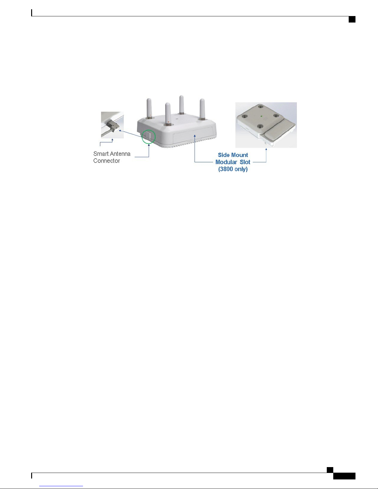
Modularity and Smart Antenna Connector Ports
The AP 3800 has modularity support that is a bit different from the original module design on the prior AP
3600 and AP 3700 series. This module design allows for installation onto the side of the access point. This
allows for larger antenna arrays and does not constrict the development of Cisco and potentially third party
modules as they are no longer limited by the physical size of the cccess point. Additionally, filtering is installed
on the AP 3800 for cellular and other radio coexistence.
The external antenna connectors on the "E" and "P" series are identical to the antenna connectors on previous
access points. There is no difference in operation when the access point is used in dual band (2.4 and 5 GHz)
operation. which is the default mode. RF coverage and cell sizes are similar to the previous AP 2700 and 3700
series so there is no need to do a new site survey.
Unlike the prior external antenna versions, the new 2800 and 3800 series Access Points now support the
capability of dual 5–GHz operation. When in this mode, a smart antenna connector must be used on the
external antenna models, as the additional 5–GHz radio cannot use the same top antennas on the access point
that are being used by the primary 5–GHz radio.
Cisco Aironet Series 2800/3800 Access Point Deployment Guide
10
Page 15
Choosing the Right Access Point
When a smart antenna connector is installed, the XOR radio (the radio that is defined in software as Radio 0)
now has its RF switched to the smart antenna connector.
Figure 10: External connector ports on AP 2800e and 3800e
Modularity and Smart Antenna Connector Ports
Cisco Aironet Series 2800/3800 Access Point Deployment Guide
11
Page 16

Modularity and Smart Antenna Connector Ports
Choosing the Right Access Point
Cisco Aironet Series 2800/3800 Access Point Deployment Guide
12
Page 17

CHAPTER 3
Physical Hardware and Mounting Options
Access Point Physical Hardware and Mounting Options, page 13
•
Access Point Physical Hardware and Mounting Options
AP 2800 and AP 3800 have similar physical dimensions with only slight differences in physical appearance
mostly to accommodate the different features like modularity and Multigigabit support resulting in slight
differences in width.
There are many different installation options available depending upon the business requirements. Brackets
are available from Cisco as well as third-party companies. During the ordering process, the customer may
choose one of two brackets (but not both). Each bracket is a zero-dollar ($0) option at the time of configuration.
If the customer does not choose a bracket, the selection default is AIR-AP-BRACKET-1, which is the most
popular for ceiling installations. The other choice is a universal bracket that carries part number
AIR-AP-BRACKET-2.
Note
The AP 2800 and AP 3800 is noticeably heavier than the AP 2700 and AP 3700. This is due to the powerful
design of the components used, which include a dual core processor, 12 radio transceivers, additional
memory and processor power as well as additional Ethernet capability including mGig on the AP 3800
and optional module support.
Cisco Aironet Series 2800/3800 Access Point Deployment Guide
13
Page 18
Channel Rail Adapters
Physical Hardware and Mounting Options
The mounting brackets and ceiling rails easily handle the extra weight and the intent was to make a very robust
Access Point without the need for vent holes and to allow the product to be used in industrial and manufacturing
areas as well as commercial enterprise environments.
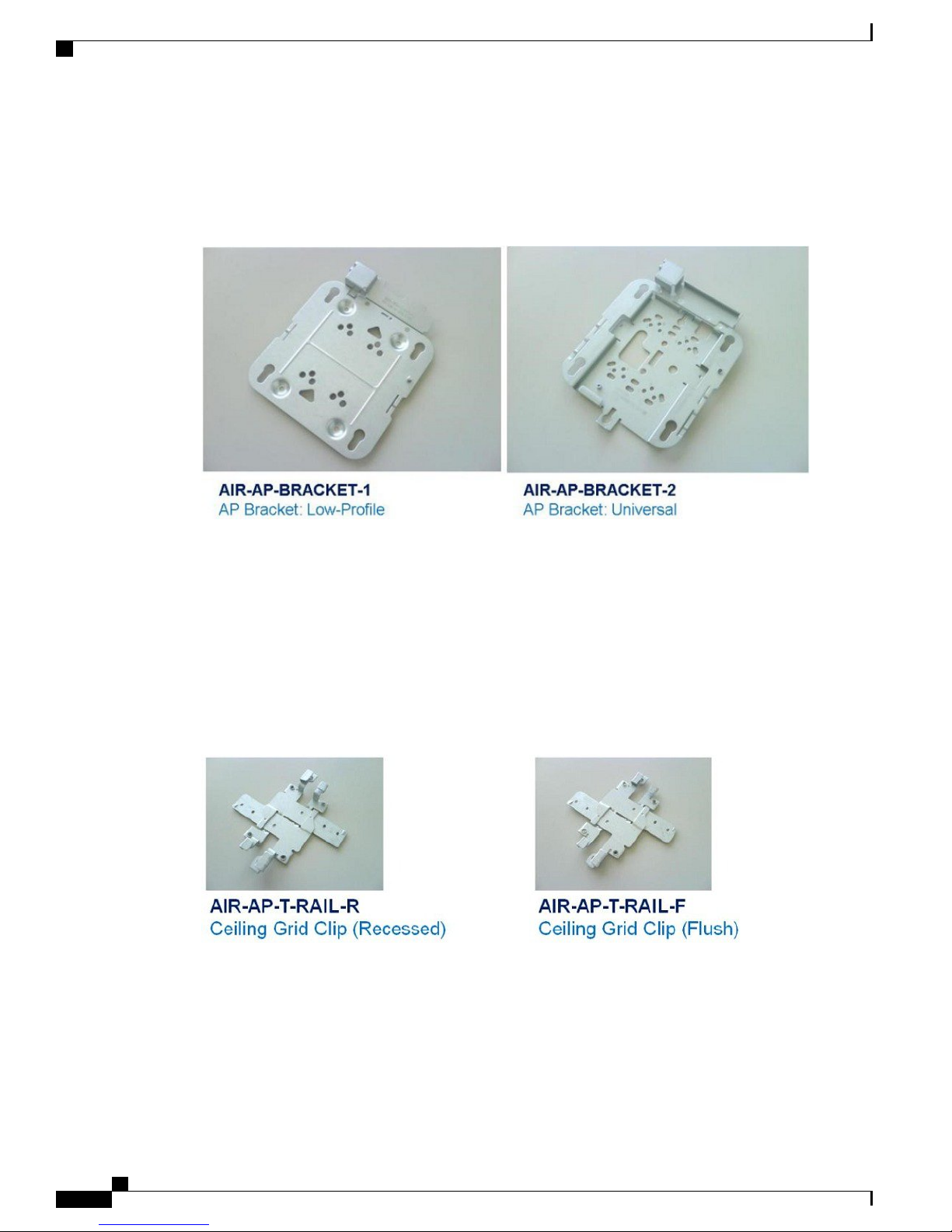
Figure 11: Access Point Bracket Choices
If the AP will be mounted directly to a ceiling on the gridwork, then AIR-AP-BRACKET-1 mounts flush and
has the lowest profile. However, if the AP will be mounted to an electrical box or other wiring fixture, or
inside a NEMA enclosure or perhaps wall mounted, then AIR-AP-BRACKET-2 is a much better choice. The
extra space in the bracket allows for wiring, and the extra holes line up with many popular electrical boxes.
When mounting the bracket to the ceiling gridwork, some ceiling tiles are recessed. For this reason, two
different styles of ceiling clips, recessed and flush rails, are available.
For new installations AIR-BRACKET-2 is recommended as it provides a little extra room and accomodates
earlier access points with modules, so it truly is a universal bracket.
Figure 12: Different clips are available for attaching to ceiling grid work
Channel Rail Adapters
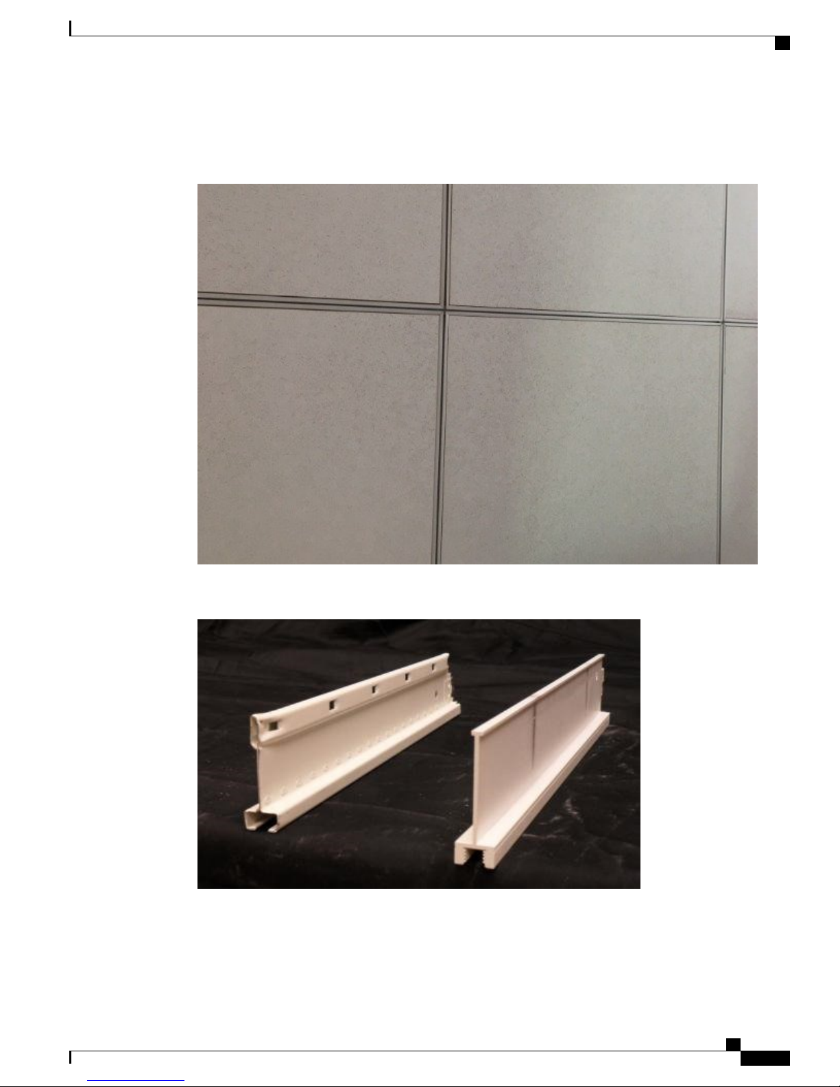
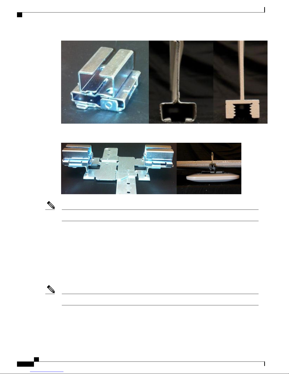
When mounting APs to ceiling channel rails such as the ones shown in Figure 14, an optional channel adapter
is used: AIR-CHNL-ADAPTER. It comes in a two-pack and attaches to the ceiling grid clip above.
Cisco Aironet Series 2800/3800 Access Point Deployment Guide
14
Page 19
Physical Hardware and Mounting Options
Thin rail or sometimes referred to as recessed ceiling rails often look like as shown.
Figure 13: Example of a recessed ceiling rail system
Channel Rail Adapters
Figure 14: Example of Channel Rails used on thin rail (recessed rail) ceilings
Figure 15: AIR-CHNL-ADAPTER (left) Slides onto the Rails
Cisco Aironet Series 2800/3800 Access Point Deployment Guide
15
Page 20
Mounting an AP Directly into the Tile Using Optional AIR-AP-BRACKET-3
Figure 16: AIR-CHNL-ADAPTER Mounted to Rail Clip (left) and Finished Installation (right)
Physical Hardware and Mounting Options
When ordered, part numbers are replacement numbers so they end with an "=".Note
AIR-AP-T-RAIL-R=Ceiling Grid Clip–Recessed
AIR-AP-T-RAIL-F=Ceiling Grid Clip–Flush
AIR-AP-BRACKET-1=AP Bracket–Low Profile
AIR-AP-BRACKET-2=AP Bracket –Universal
AIR-CHNL-ADAPTER=Additional Adapter for Channel–Rail Ceiling Grid profile
Mounting an AP Directly into the Tile Using Optional AIR-AP-BRACKET-3
This bracket is not compatible with the AP 2800 and AP 3800 Series.Note
If you have this bracket currently installed and are migrating to the newer AP 2800 and AP 3800 series, you
may be able to still use the existing tile and leverage the new in-tile mount available from Oberon Wireless
(a Cisco partner).
Cisco Aironet Series 2800/3800 Access Point Deployment Guide
16
Page 21
Physical Hardware and Mounting Options
For completeness, here is an overview of the existing AIR-BRACKET-3 so you may understand it better
should you encounter it within your deployments. Many hospitals and other carpeted Enterprise environments
prefer a more streamlined look and wish to install the AP directly into the tile. This can be done on prior Cisco
AP products using the optional Cisco AIR-AP-BRACKET-3.
When using this bracket, the "beauty ring" is used as the template to cut the tile which can be cut using a
carpet knife or electric tool such as a rotary cutting tool, e.g., Dremel or Rotozip. Cisco does not offer custom
cut tiles as there are simply too many different styles and the tiles are easy to cut.
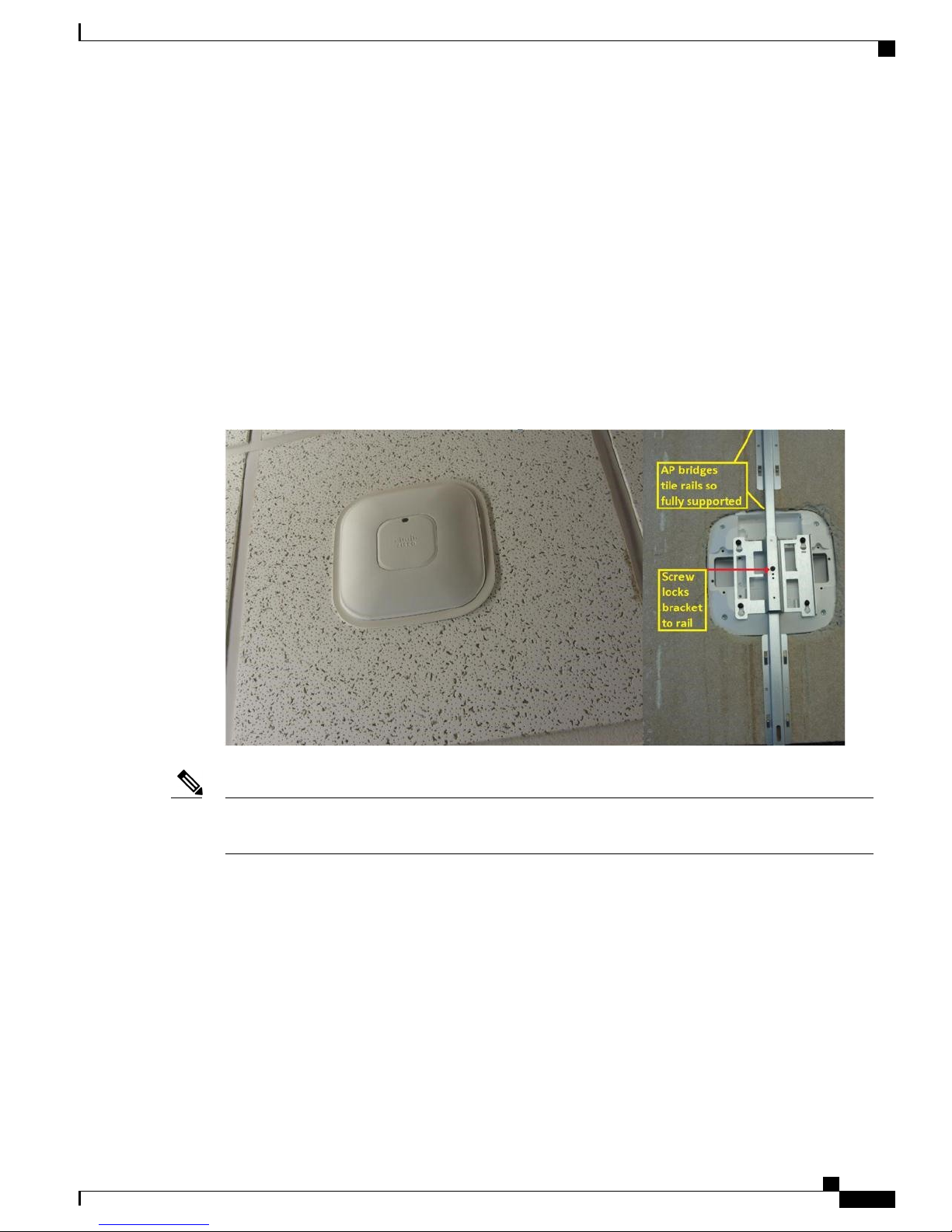
The AP is fully supported above the tile with a metal rail that extends the length of the tile. This supports the
AP should the tile become wet or otherwise fail. A mechanical set screw pulls the AP tight to the ceiling and
locks it into the bracket. Additionally, physical security of the AP can be maintained by the use of a Kensington
style lock, but once installed it is difficult to remove the AP without removing the tile as the AP will not slide
out from the front side of the tile.
Figure 17: Optional AIR-AP-BRACKET-3 to install the AP directly into the tile
Mounting an AP Directly into the Tile Using Optional AIR-AP-BRACKET-3
Note
This bracket fits the AP-1040, 1140, 1260, 1600, 2600, 3500, 3600 and 3700 Series Access Points; however,
it is not compatible with the 2800 and 3800 series.
Cisco Aironet Series 2800/3800 Access Point Deployment Guide
17
Page 22
Using an In-tile Mount from Oberon Wireless
Using an In-tile Mount from Oberon Wireless
Figure 18: Oberon in tile and above tile mounting solutions
Physical Hardware and Mounting Options
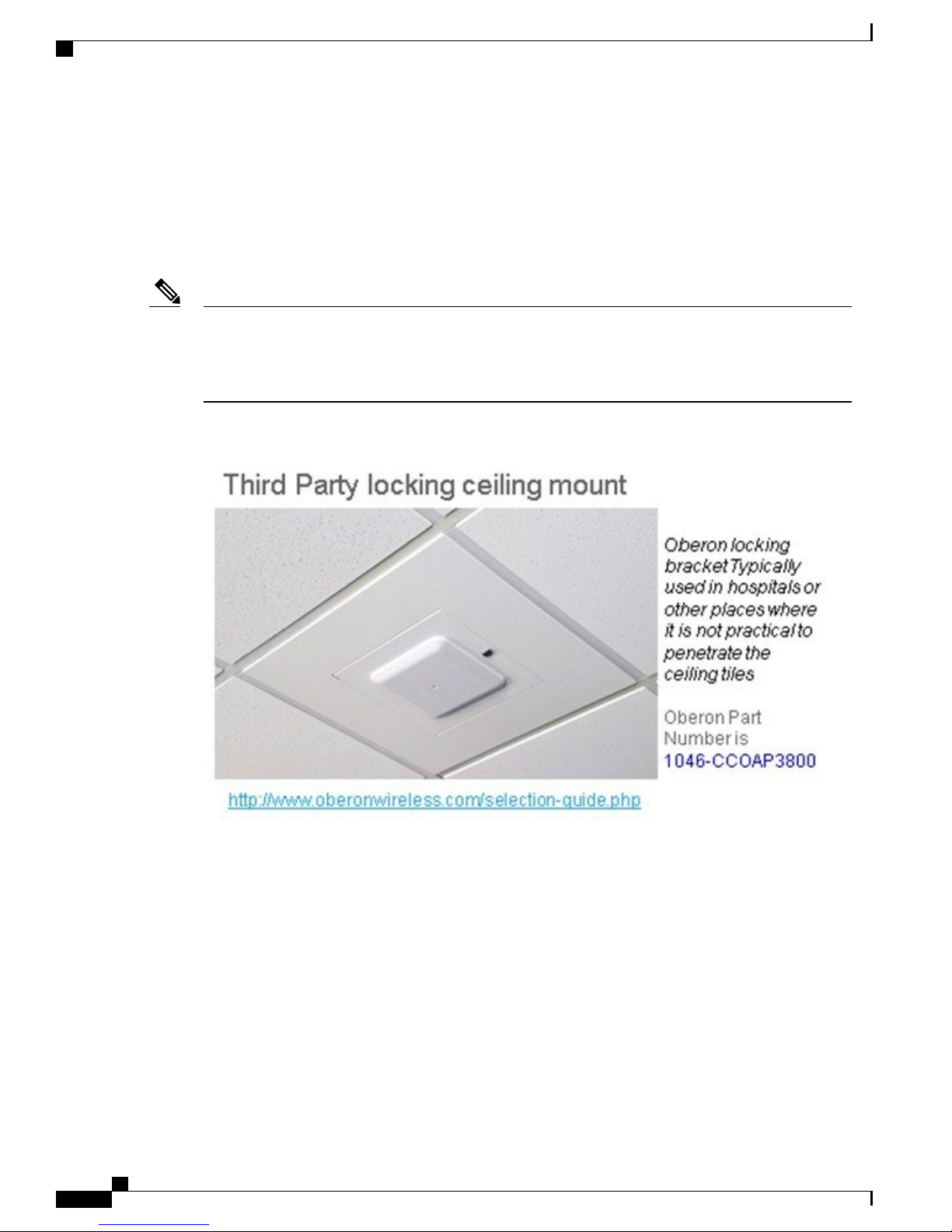
Additionally, Oberon offers a metal locking cabinet that allows the Access Point to be mounted flush to the
ceiling, which is often used in hospital infection control areas or places where higher physical security is
required.
Wall-mounting the AP
When wall mounting is desired, the installer should understand that walls can be a physical obstacle to the
wireless signal; therefore, maintaining 360–degree coverage may be compromised by the wall. If the wall is
an outside wall and/or the goal is to send the signal in a 180-degree pattern instead, a directional antenna often
Cisco Aironet Series 2800/3800 Access Point Deployment Guide
18
Page 23
Physical Hardware and Mounting Options
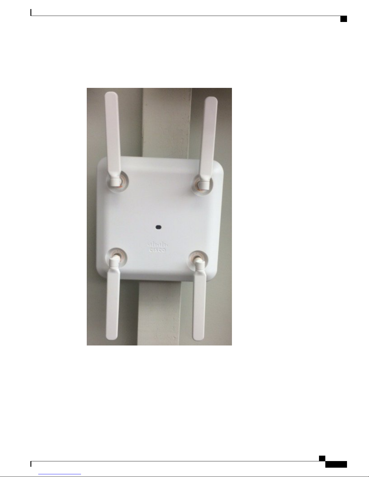
referred to as a "patch" antenna may be a better choice assuming the AP 2800e or AP 3800e is used. Instead,
use the AP 2800e or AP 3800e (with dipoles pointing vertical).
Figure 19: Correct orientation of dipole antennas when mounted on a vertical surface
Wall-mounting the AP
Figure 20: Avoid wall mounting units with internal antennas
Cisco Aironet Series 2800/3800 Access Point Deployment Guide
19
Page 24
Wall-mounting the AP
Physical Hardware and Mounting Options
Cisco Aironet Series 2800/3800 Access Point Deployment Guide
20
Page 25
Physical Hardware and Mounting Options
Changing the Color of an AP
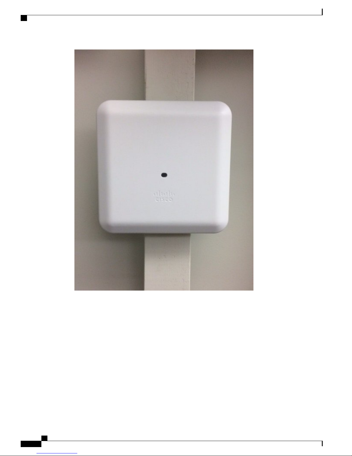
Note
Wall mounting units with internal antennas in the orientation shown in Figure 20: Avoid wall mounting
units with internal antennas should be avoided. AP 2800i & AP 3800i should use the Oberon mounting
bracket unless roaming is not an issue, example: hotspot, kiosk, or very small venue areas where large
uniform coverage is not needed.
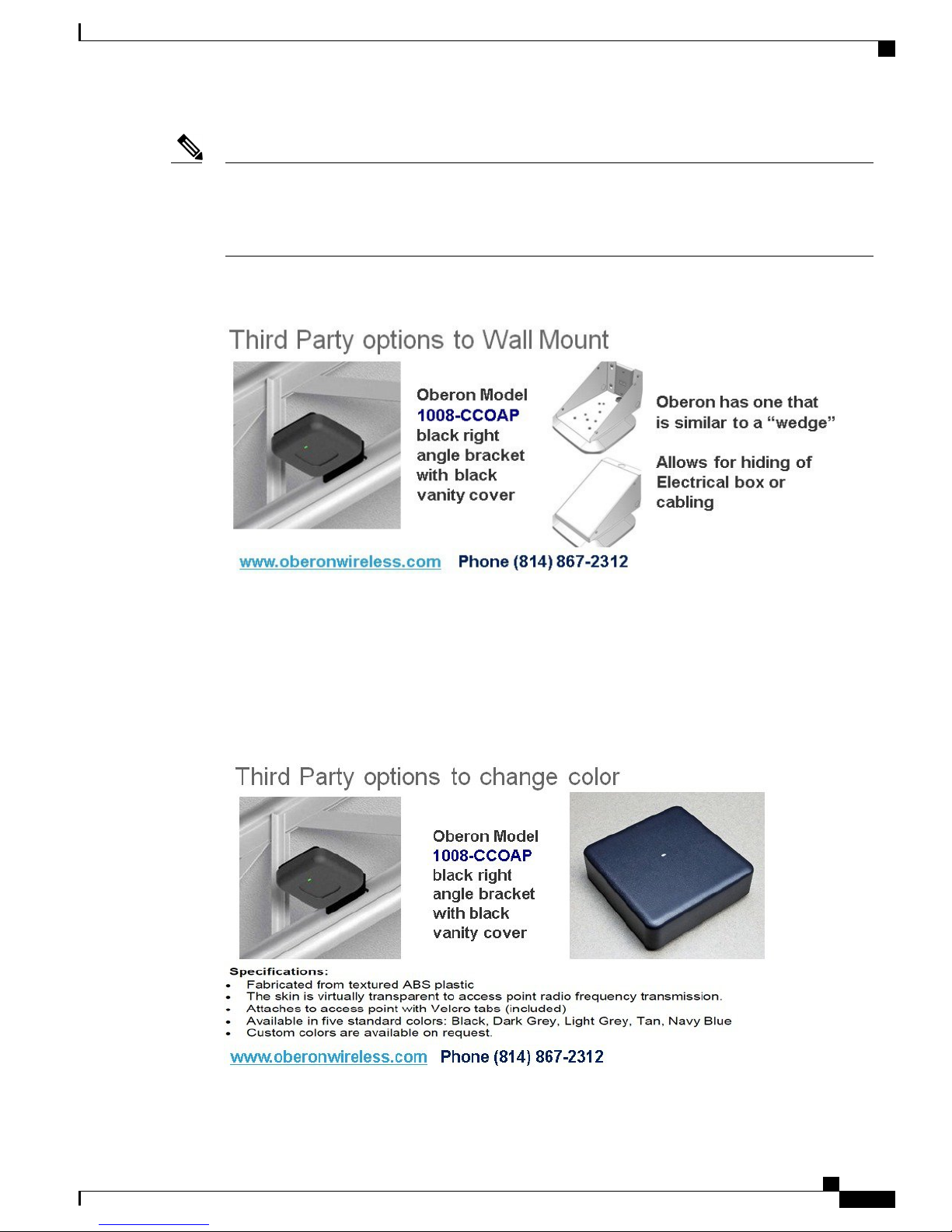
Figure 21: Third Party options to Wall Mount
Changing the Color of an AP
If there is a desire to change the color of an AP, rather than painting the AP which would void the warranty,
consider using colored vinyl tape or using a colored plastic cover from Oberon.
Figure 22: Third-party option for changing AP color, adding custom Logo, or hiding the LED
Cisco Aironet Series 2800/3800 Access Point Deployment Guide
21
Page 26
Clean Rooms (Healthcare)
Clean Rooms (Healthcare)
Many hospitals and factories have requirements to wipe down or gently spray the environment with a chemical
(often diluted liquid that has cleaning / disinfectant properties). The Cisco AP 2800 and AP 3800 are designed
with a purpose–build Wi-Fi chipset using Enterprise and industrial class components. This enables the AP
enclosure to have a Plenum rating and is vent-less, so the unit is ideal for these types of applications.
Physical Hardware and Mounting Options
Note
The plastic material used on the AP 2800 and AP 3800 series is Lexan 945. This material was tested for
clean room use with a Steris chemical, trademark name SPOR-KLENZ. See http://
www.sterislifesciences.com/Products/Surface-Disinfectants-Cleaners-and-Alcohols/Sporicides-Sterilant/
Spor-Klenz-Ready-To-Use-Cold-Sterilant.aspx
Figure 23: Third Party Locking Ceiling Mount
Above the Ceiling Tiles
The AP 2800 and 3800 are rated for installation in the Plenum area (UL-2043). Many customers prefer to
locate the AP so that nothing can be visible on the ceiling. In some cases this is preferred for aesthetic reasons,
so customers may install the AP above a drop ceiling. This also may be preferred in high theft areas such as
classrooms or in areas where policy dictates that nothing can be visible on the ceiling.
Cisco Aironet Series 2800/3800 Access Point Deployment Guide
22
Page 27
Physical Hardware and Mounting Options
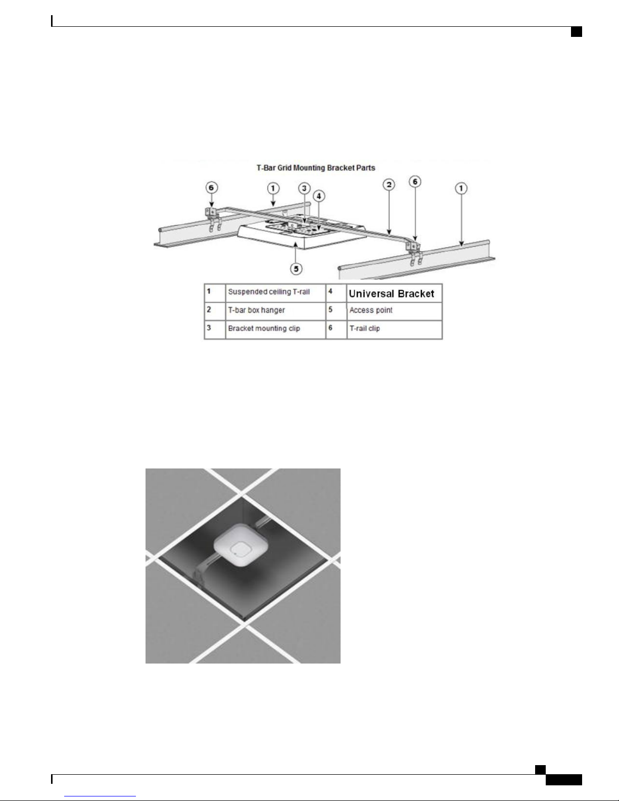
When this is a hard requirement, optional T-Bar hangar accessories from third-party companies such Erico
and Cooper can be used. The Erico Caddy 512a or the Cooper B-Line BA50a or similar T-Bar Grid T-Bar
hangars can be used.
Figure 24: Example of How to Hang an AP above the Ceiling Tiles
Above the Ceiling Tiles
For more information see:
http://www.erico.com/
http://www.cooperindustries.com/
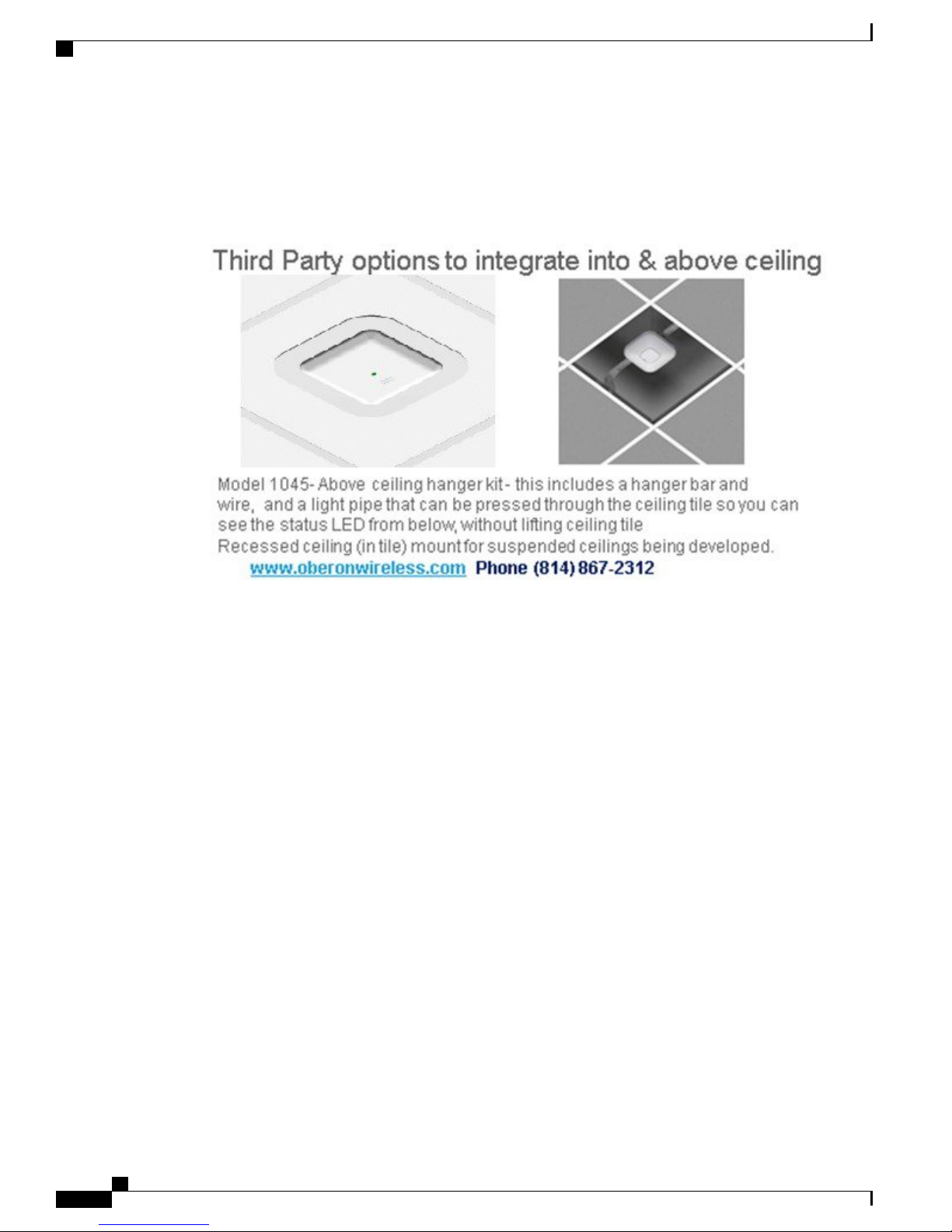
Additionally, Oberon also offers above tile solutions.
Figure 25: Oberon Model 1045- Above ceiling hanger kit - this includes a hanger bar and wire, and a light pipe that can
be pressed through the ceiling tile so you can see the status LED from below, without lifting ceiling tile
Cisco Aironet Series 2800/3800 Access Point Deployment Guide
23
Page 28

Above the Ceiling Tiles
Physical Hardware and Mounting Options
Note
Installing APs above the ceiling tiles should only be done when mounting below the ceiling is not an
option. The tiles must not be conductive; such installations can certainly degrade advanced RF features
such as voice and location, so verify coverage and performance. Always try to mount the AP as close to
the inside middle of the tile as possible, and avoid areas with obstructions.
Figure 26: Installing AP above ceiling tiles: Pick an area clear of obstructions, avoid ceiling clutter
Cisco Aironet Series 2800/3800 Access Point Deployment Guide
24
Page 29

CHAPTER 4
Understanding Flexible Radio Assignment
(software overview)
Understanding Flexible Radio Assignment (Software Overview), page 25
•
Understanding Flexible Radio Assignment (Software Overview)
The AP 2800 and 3800 contain a Flexible Radio Architecture; In a sense the AP is a tri-band radio as it contains
a dedicated 5–GHz radio to serve clients and another Flexible Radio (known as an XOR radio) that can be
assigned different functions within the network.
The flexible radio is similar to the previous XOR radio used in the Cisco WSSI/WSM modules for the AP
3700, but this new flexible radio module is able to be configured to serve clients in either 2.4-GHz or 5–GHz
or serially scan both 2.4-GHz and 5–GHz on the flexible radio while the main 5–GHz radio serves clients.
Figure 27: Flexible Radio Assignment
Cisco Aironet Series 2800/3800 Access Point Deployment Guide
25
Page 30

Flexible Radio Architecture (FRA) System
Flexible Radio Architecture (FRA) System
In addition to the dedicated 5–GHz radio, FRA enabled APs like the AP2800 and AP 3800 contain an additional
integrated 2.4/5–GHz XOR "selectable radio" for additional flexibility.
An FRA system uses a special XOR radio that consists of the following:
• 2.4–GHz and 5–GHz on the same silicon
• Allows selection of 2.4–GHz or 5–GHz for serving clients (default is 2.4–GHz)
• Allows serial scanning of all 2.4–GHz and 5–GHz channels (in monitor “WSM” mode)
• Role selection is manual or Automatic–RRM
Previous WSSI or WSM modules for 3700 were XOR in design
•
This feature is now integrated into AP 2800 and AP 3800
•
The benefits of an FRA system are many and address the following issues:
Understanding Flexible Radio Assignment (software overview)
• Solves the problem of 2.4–GHz over-coverage
• Creating 2 diverse 5–GHz cells doubles the airtime available
• Permits one AP with one Ethernet drop to function like two 5–GHz APs
Introduces concept of Macro/Micro cells for airtime efficiency
•
Allows more bandwidth to be applied to an area within a larger coverage cell
•
Can be used to address non-linear traffic
•
Enhances the High Density Experience(HDX) with one AP
•
XOR radio can be user selected in either band servicing clients or in monitor mode
•
When using FRA with the internal antenna ("I" series models), two 5–GHz radios may be used in a Micro/Macro
cell mode. When using FRA with external antenna ("E/P" models) the antennas may be placed to enable the
creation of two completely separate Macro (wide area cells) or two Micro cells (small cells) for HDX or any
combination.
Cisco Aironet Series 2800/3800 Access Point Deployment Guide
26
Page 31
CHAPTER 5
Client Roaming in a Micro and Macro Cell
Understanding Macro and Micro Cells, page 27
•
Understanding Macro and Micro Cells
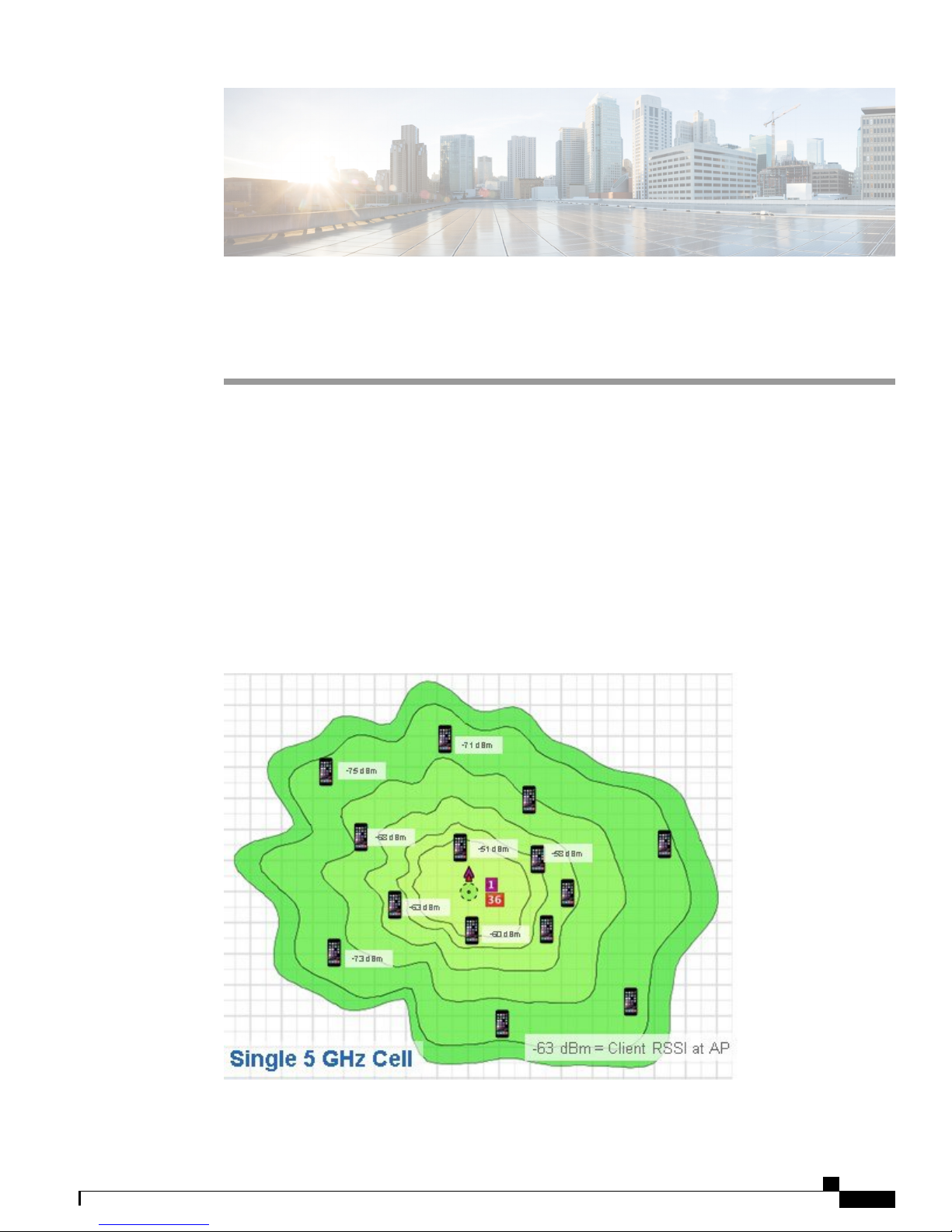
In areas where the AP traditionally has a wide-area coverage clients connected close to the AP are the most
spectrum efficient since they are in the near field and negotiate typically at the highest data rates while clients
farther away compete at lower data rates. The lower rate clients that are farther away tend to take more airtime
than the closer clients running at faster rates. This results in non-linear traffic and increases the overall channel
utilization as clients compete for "airtime".
Figure 28: Single 5 GHz and 2.4 GHz cell (default mode) Channel Utilization at 60%
Cisco Aironet Series 2800/3800 Access Point Deployment Guide
27
Page 32
Understanding Macro and Micro Cells
In the figure above, clients farther away are on the air more (sending longer, slower rate packets). The 2.4–GHz
channels (channel 1) will typically propagate farther than 5–GHz so often the 2.4–GHz radio is redundant
and in some cases is even turned off. So now the AP is covering a single 5–GHz cell in a Macro or large cell
mode.
Using FRA, you can either automatically enable an additional 5–GHz cell using Radio Resource Management
or you can manually decide that you would like to turn the XOR radio from its default 2.4– GHz to an additional
5–GHz cell.
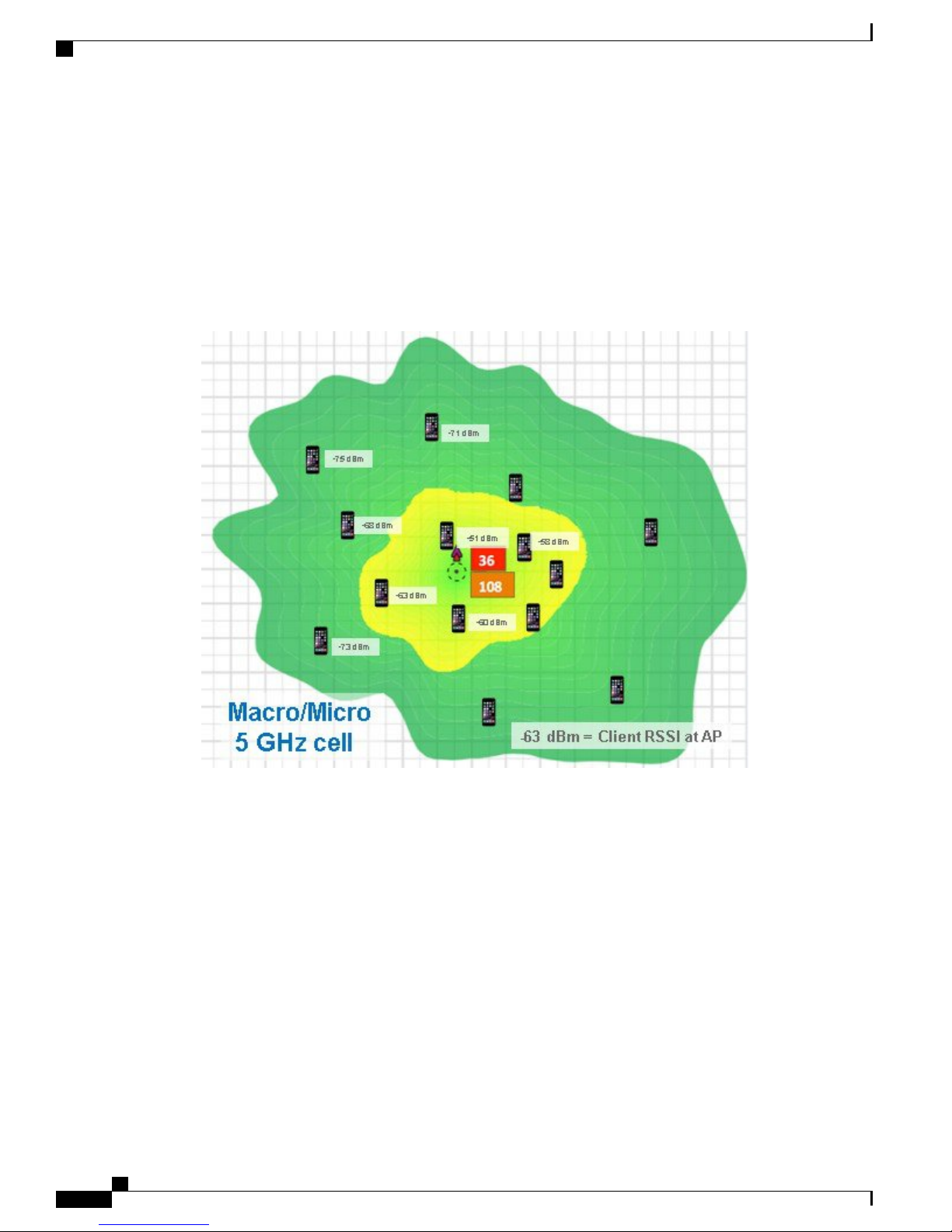
Figure 29: Enabling the FRA XOR radio as a dual 5 GHz AP creating Micro (yellow) and Macro (green cell)
Client Roaming in a Micro and Macro Cell
By optimizing the FRA to enable the access point to have two 5–GHz radios, this solves the problem of too
much 2.4–GHz coverage while creating two completely RF diverse 5–GHz cells. This not only doubles the
air time available to the 5–GHz clients, it also optimizes the client throughput by keeping like clients together
for better spectrum efficiency.
Now instead of 60% channel utilization with the clients in near field competing for airtime from the slower
farther away clients, like clients are now grouped with similar data rate characteristics.
Net result, channel utilization is now reduced to 20% on channel 36 and 24% on channel 108.
Currently both Macro (green) and Micro (yellow) cells use the same SSID by design; later releases will likely
allow for different SSIDs.
Cisco Aironet Series 2800/3800 Access Point Deployment Guide
28
Page 33
Client Roaming in a Micro and Macro Cell
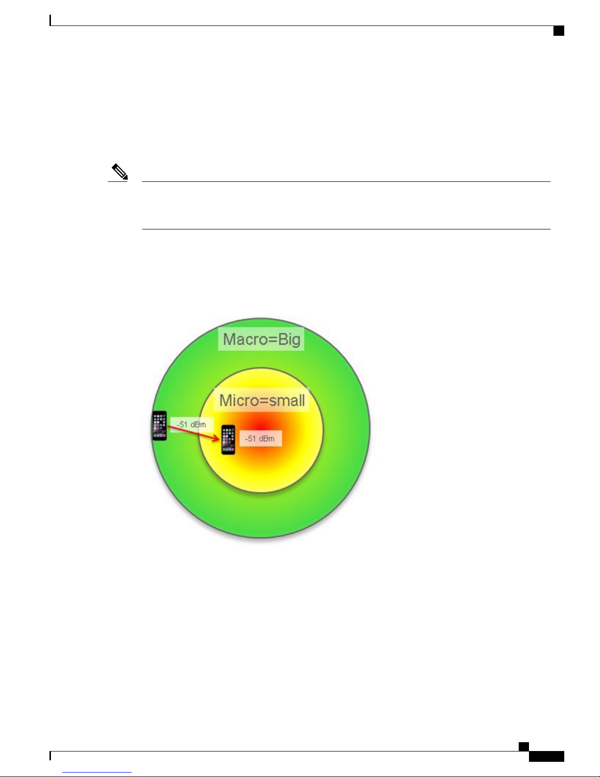
Client Roaming from a Macro to Micro Cell
The most likely scenario is that a client will associate to the Macro cell first as it will have the bigger footprint
and transmitting at a greater RF power. So in the figure below, any client that has RSSI at the AP above the
Micro cell threshold of -55 dBm will be moved into the Micro cell.
Client Roaming from a Macro to Micro Cell
Note
Note: -55 dBm is the default but configurable using the command line interface (CLI). For more on
configuring these options see the RRM guide and other resources at http://www.cisco.com/c/en/us/support/
wireless/wireless-lan-controller-software/products-technical-reference-list.html
In addition to the threshold, if the client supports 802.11v, on association the AP will send an .11v BSS
transition request with the Micro cell BSSID and the only candidate. If a non .11v client, it will send an .11k
neighbor list and a disassociate packet. Other methods and optimizations are being investigated.
Figure 30: Intra-cell roaming Macro cell to Micro cell
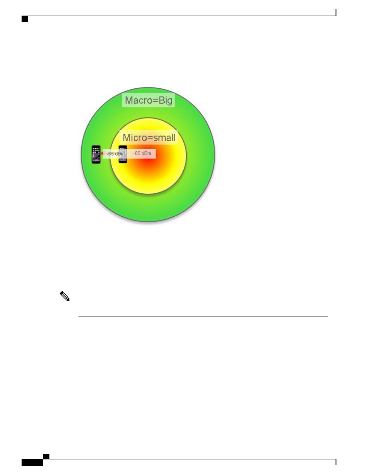
Client Roaming from a Micro to Macro Cell
When a client initially associate to the Micro cell first, while less likely but certainly possible based on device
scan and channels heard. In this case, a client that has RSSI at the AP below the Macro cell threshold of -65
dBm will be moved into the Micro cell -65 dBm by default. This is also configurable by user CLI.
If the client supports 802.11v - on association, the AP will send an 11v BSS Transition request with the Macro
cell BSSID as the only candidate.
Cisco Aironet Series 2800/3800 Access Point Deployment Guide
29
Page 34
Micro and Macro cells on “I” Series Access Points
For a non .11V client, the system sends an 11K neighbor list and a disassociate packet.
Figure 31: Intra-cell roaming Micro to Macro cell
Client Roaming in a Micro and Macro Cell
Micro and Macro cells on “I” Series Access Points
The AP 2800i and AP 3800i have integrated antennas and as such, when FRA is enabled and dual 5–GHz
operation is selected, only the non-FRA radio can perform the role of a Macro cell or Micro cell. The XOR
FRA radio when enabled for 5–GHz must operate using a much lower power and therefore must function as
a Micro cell.
The "E/P" Series with external antennas can operate in any combination of Micro or macro cells.Note
Prior to FRA technology, access points like the AP 2700 and AP 3700 defined the dedicated radios in software
as Radio 0 (2.4–GHz) and Radio 1 (5–GHz); if an additional radio like the WSM module was installed in the
AP 3700 the third radio was defined as Radio 2, sometimes called "Slot 2".
Now with FRA, Radio 0 is the 2.4–GHz radio *OR* it can be a 5–GHz radio; hence the term XOR.
By default the FRA functions as a 2.4–GHz radio, so out of the box the AP behaves the same as a conventional
AP 2700 and AP 3700 operating off the dual band Macro cell (large brass colored) antennas on the four corners
in the figure below. Additionally, the non-FRA 5–GHz radio also shares the Macro cell antennas.
If you enable the FRA radio from 2.4–GHz to 5–GHz, the FRA radio can no longer use the Macro cell antenna
on 2.4–GHz and automatically switches to another set of four Micro cell antennas. This is done because two
5–GHz radios cannot share the same antennas.
The Micro cell 5–GHz antennas are designed to co-exist in the near field of the Macro cell antennas with the
following caveats.
Cisco Aironet Series 2800/3800 Access Point Deployment Guide
30
Page 35

Client Roaming in a Micro and Macro Cell
1
Channels must not be closer than 100–MHz (RRM prevents this).
2
The Micro cell antennas are horizontal polarity and higher gain to create a smaller cell foot print.
3
RF output power on the Micro cell is significantly reduced.
Micro and Macro cells on “I” Series Access Points
Cisco Aironet Series 2800/3800 Access Point Deployment Guide
31
Page 36

Micro and Macro cells on “I” Series Access Points
4
SSIDs must be the same (this may change in later releases).
Figure 32: Picture of the embedded antenna system and 3D antenna heat maps
Client Roaming in a Micro and Macro Cell
Figure 33: Smith chart comparing radiation patterns of Macro and Micro cell antennas
Figure 34: Smith chart radiation pattern of 2.4 GHz 4 dBi Macro cell antenna
Cisco Aironet Series 2800/3800 Access Point Deployment Guide
32
Page 37
Client Roaming in a Micro and Macro Cell
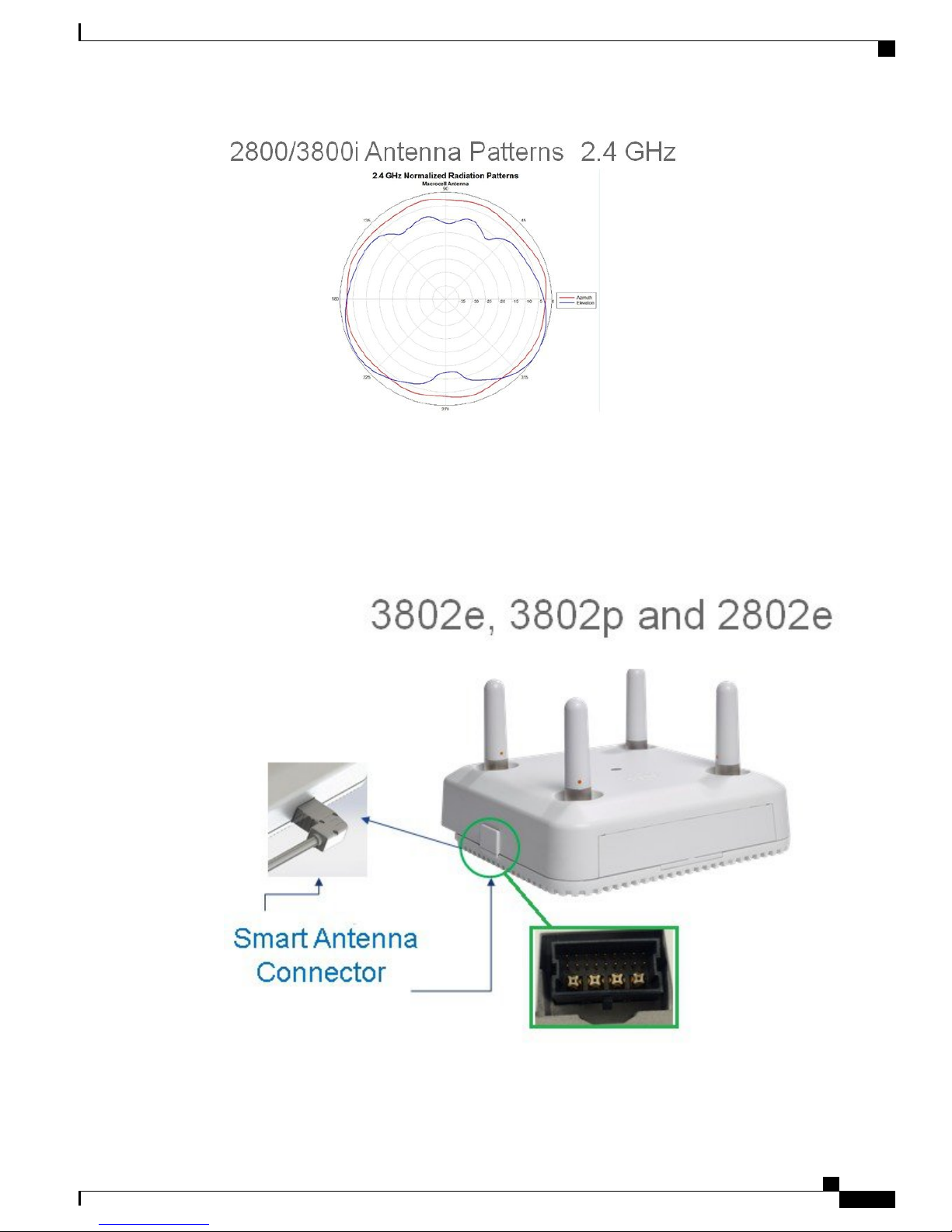
RF Operations on “E/P” Series Access Points
RF Operations on “E/P” Series Access Points
Unlike the integrated antenna models, the external antenna model units have four primary RP-TNC connectors
on top of the device and an additional four RF connectors as well as digital via a new smart antenna connector.
Figure 35: Smart antenna connector is an integrated feature of the "E/P" series products
Cisco Aironet Series 2800/3800 Access Point Deployment Guide
33
Page 38
RF Operations on “E/P” Series Access Points
When the smart antenna connector is not used, the AP 2800 and AP 3800 "E/P" series function much like an
AP 3700 where both the 2.4–GHz FRA radio and the integrated 5–GHz radio share the top RP-TNC connectors
in a dual band mode.
This is sometimes referred to as Dual Radiating Element (DRE) or dual band mode.Note
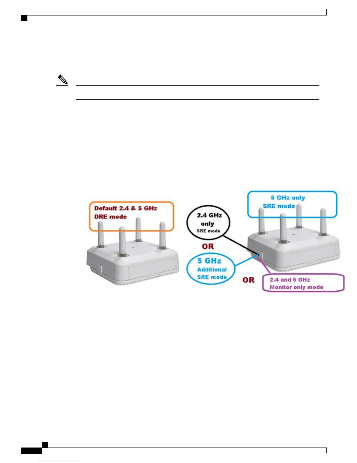
However, once the smart antenna connector is inserted, the access point senses the presence of the new
connector/antenna and automatically switches the FRA (XOR radio) from the top connector that was previously
in 2.4 GHz/5 GHz DRE mode to the smart connector port. This allows the top connectors for the 5 GHz radio
serving clients and the FRA radio is now free (regardless of mode) to use the smart connector for RF
communications.
The flexibility to do this allows many different types of modes, from discrete single band operation (SRE) to
DRE operation. The ability to change the antenna controls (sending different bands 2.4 GHz and 5 GHz out
of different ports in SRE and/or DRE mode) is sometimes referred to as Cisco "Flexport" and was first
introduced in the AP-1530 series.
Figure 36: Antenna control (default) and with smart antenna connector installed
Client Roaming in a Micro and Macro Cell
Cisco Aironet Series 2800/3800 Access Point Deployment Guide
34
Page 39
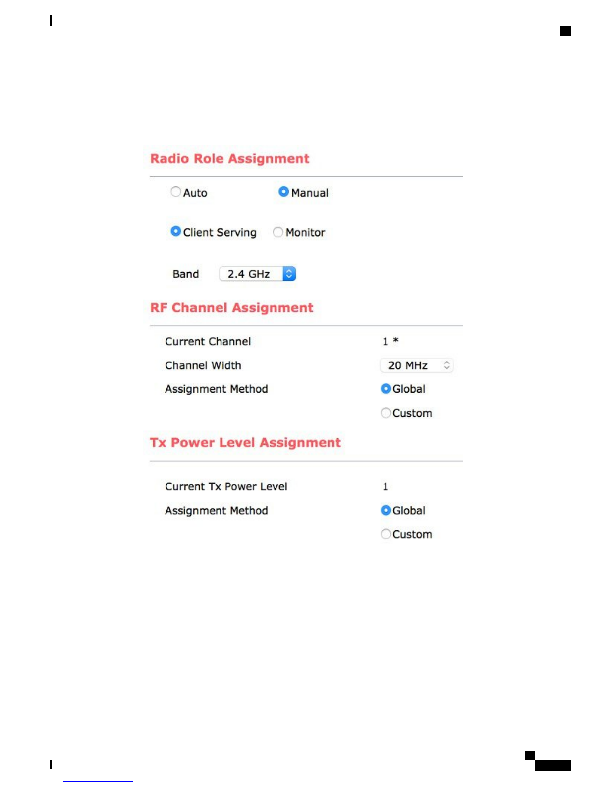
Client Roaming in a Micro and Macro Cell
The role of the XOR radio is selected in software, and the modes are Band, Client Serving or Monitor mode.
This can be set manually or automatically if RRM control is desired.
Figure 37: FRA (XOR) radio defaults to 2.4 GHz Client serving but is selectable in software
RF Operations on “E/P” Series Access Points
Cisco Aironet Series 2800/3800 Access Point Deployment Guide
35
Page 40
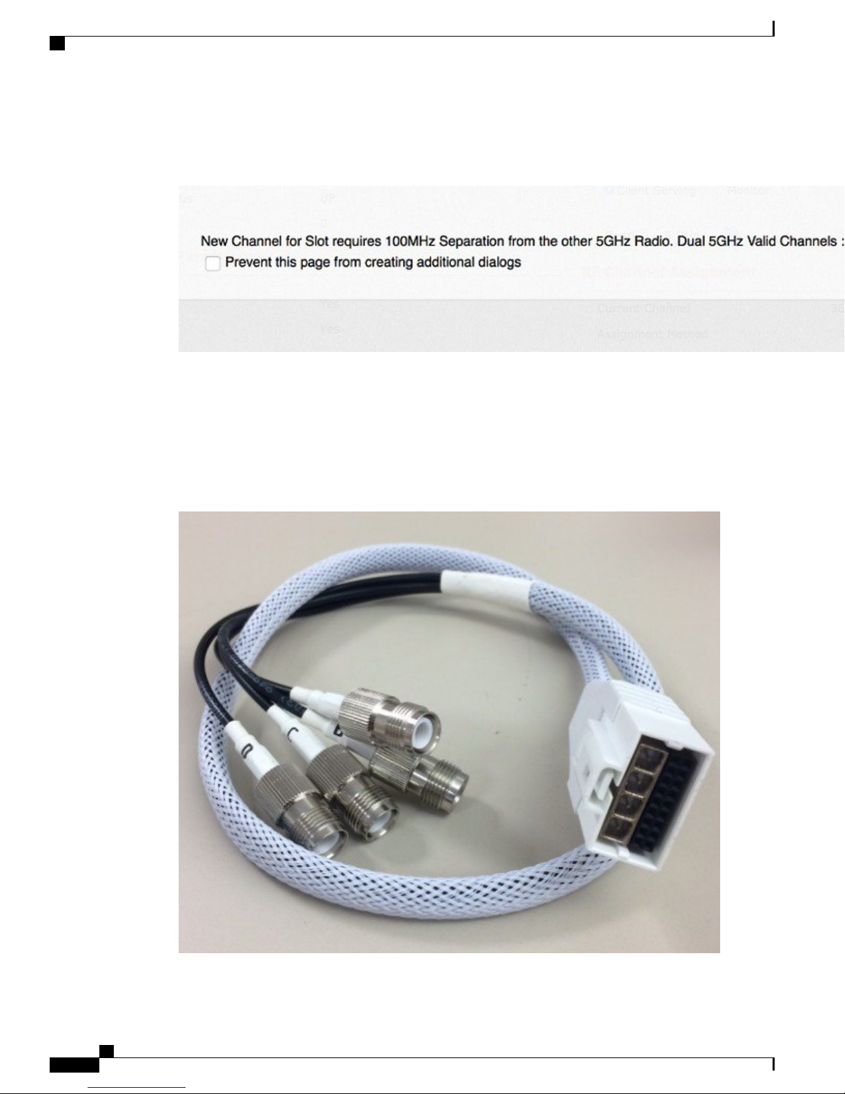
RF Operations on “E/P” Series Access Points
If you change the band from 2.4 GHz to 5 GHz then you must have 100–MHz separation.
Figure 38: Error when channels are set too close
If the antenna has a smart antenna connector it allows the AP to sense what type of antenna is installed and
configure the AP accordingly.
Using the smart antenna connector to RP-TNC adapter AIR-CAB002-DART-R the FRA (XOR) radio can
now be used in many applications as the RF system on the FRA (XOR) radio will now use the four external
RP-TNC connectors for a wide variety of application deployments.
Client Roaming in a Micro and Macro Cell
Figure 39: Cisco Smart Antenna Adapter AIR-CAB002-DART-R
Cisco Aironet Series 2800/3800 Access Point Deployment Guide
36
Page 41
Client Roaming in a Micro and Macro Cell
The smart RF antenna connector sometimes referred to as a DART carries the digital signals (18 mins) as
well as the four analog RF ports from the XOR radio.
The term DART is an Amphenol trademark name for this type of connector.Note
Unlike the internal models, the smart connector allows both antenna systems to be located away from each
other enabling deployments that cannot be done with the internal model. For example, the creation of two
5–GHz Macro cells is not possible in addition to separating the 5–GHz cells into different areas (think
inside/outside) or different coverage areas in a factory or stadium.
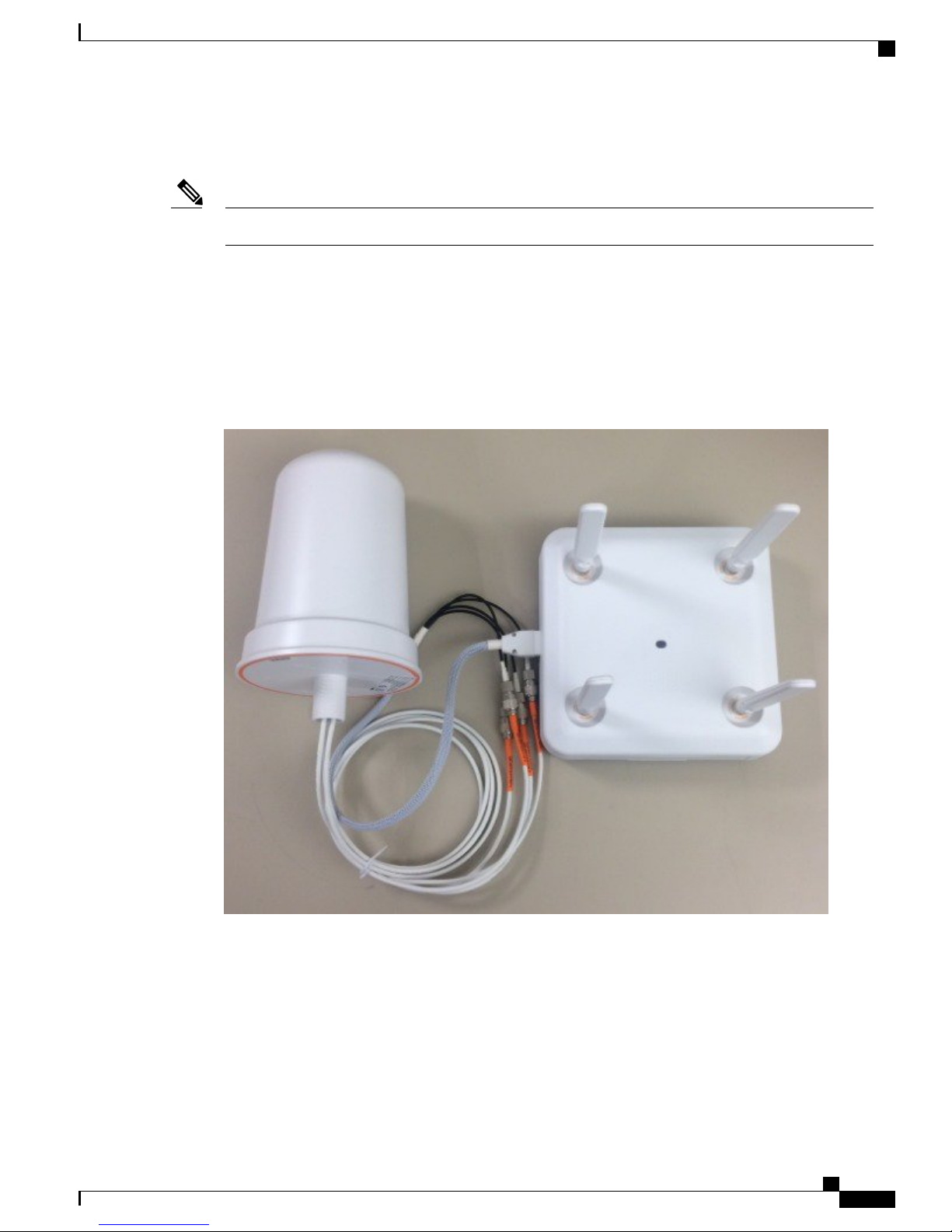
Sometimes unique customer requirements dictate that 2.4–GHz RF operation be on one set of antennas and
5 GHz on a completely different set of antennas, and that is also possible.
Figure 40: Smart antenna cable adapter and the Cisco external Omni antenna
RF Operations on “E/P” Series Access Points
Since both sets of antennae can be physically spaced apart, many new RF design opportunities become available
allowing for many different types of new and unique installations.
Some deployment options include:
1
Omni and directional deployments (think hospital room and a long hallway) with one AP
2
Any combination of Micro and Macro cell deployments
3
Using stadium antennas, two different 5–GHz coverage cells can be done with 1 AP
Cisco Aironet Series 2800/3800 Access Point Deployment Guide
37
Page 42

RF Operations on “E/P” Series Access Points
4
High ceilings (factory and warehouse deployments) can use back to back 6 dBi Patch antennas
5
AP using 2x 5–GHz radio can double the coverage with the addition of one antenna
6
Conference centers and other locations can double capacity on existing Ethernet cable plan
7
One access point can support both indoor and outdoor deployments
8
Access point can serve 5–GHz clients while performing full 2.4 & 5–GHz wireless monitor radio
When using the smart antenna connector and dual 5–GHz mode the caveats are:
1
Channels must not be closer than 100–MHz
2
Antennas should not be mounted so that energy from one antenna is directed into another
3
Ideally if one antenna is Omni then 6 ft or 2 meter physical separation
4
Antennas may be closer if used in Micro cell (very low power) is used
5
Any combination of Micro/Macro can be used as long as physical isolation exists
6
SSIDs must be the same (this may change in later releases)
Client Roaming in a Micro and Macro Cell
Figure 41: Example using "E/P" version to create two macro cells can be supported
Cisco Aironet Series 2800/3800 Access Point Deployment Guide
38
Page 43
CHAPTER 6
Approved Antennas for Use with Access Points
2800 and 3800
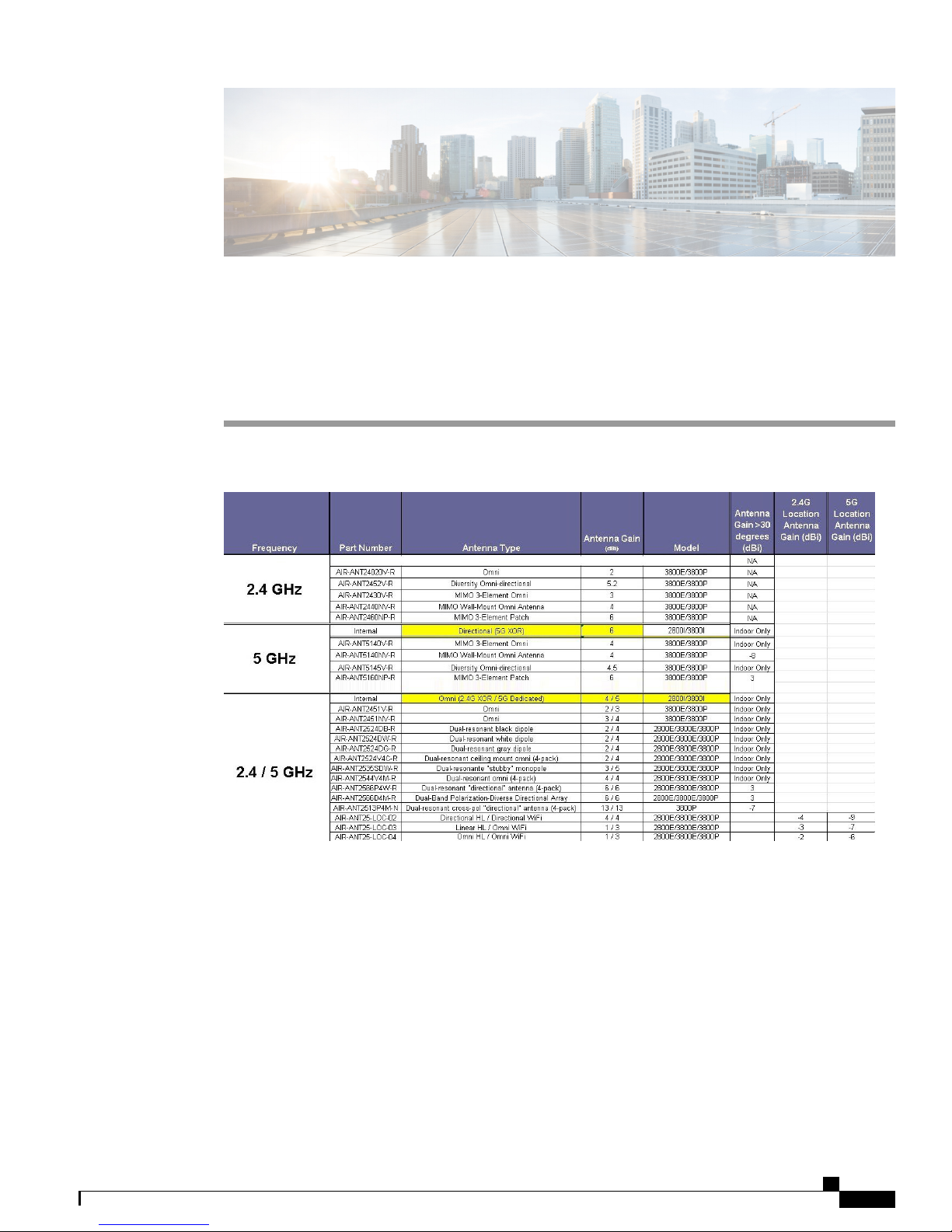
Figure 42: Approved list of external antenna for use with 2800E/3800E/3800P
The above list is the approved antennas for use in the US Theater using the FCC –B domain.The new –B
products allow for outdoor use provided the correct antenna is used. Customers should avoid using UNII-1
band outdoors in the US unless the –P version is used.
Cisco Aironet Series 2800/3800 Access Point Deployment Guide
39
Page 44

Approved Antennas for Use with Access Points 2800 and 3800
Cisco Aironet Series 2800/3800 Access Point Deployment Guide
40
Page 45

CHAPTER 7
AP 2800 and AP 3800 Powering Options
With each advance in wireless technology, access points are increasing in the number of radios, processing
power and memory. In 2001 the AP-350 Access Point had one 2.4 GHz radio and processor requiring only
6 Watts of power. These early PoE access points would fully function using the earlier 802.3af (15.4W)
powering systems developed in 2000-2003.
Figure 43: Early AP-350 used 6 Watts-Newer AP 3800 requires 802.3at or PoE+
Later PoE standards have since emerged with 802.3at providing up to 30 Watts at the Power Sourcing
Equipment (PSE). Many of Cisco's previous access points such as the AP-1850 and AP-3700 worked best
with the higher power sources 802.3at and PoE+ but would function with "reduced functionality" if powered
by the older 802.3af 15.4W powering systems.
With the introduction of the XOR radio along with more advanced features, it simply is not feasible to run
these higher performance access points on the older legacy 802.3af (15.4W) powering systems. Customers
who have such older systems should upgrade to 802.3at (30W) PoE equipment or systems that support uPoE
for best performance or use a different power source such as a mid-span injector or local power supply. Note:
Cisco Aironet Series 2800/3800 Access Point Deployment Guide
41
Page 46

AP 2800 and AP 3800 Powering Options
If the AP2800 and AP 3800 are powered from an 802.3af power source the LED will cycle though the colors
and the radios will be disabled.
Performance requires power as the AP 2800 and AP 3800 have much more advanced features such as:
1
Dedicated microprocessor and memory for each radio band
2
Dual core processor to manage access point and Ethernet functionality
3
Additional XOR radio and antenna switching circuitry, pushing transceiver count to 12 radios
4
Cisco CleanAir silicon for complete spectrum analysis and interference detection
5
Cisco ClientLink powerful (legacy .11a/g/n and .11ac Wave 1 beamforming)–improving older client
connectivity and performance; IEEE specification is limited to only TxBF on 802.11ac Wave-2 clients
6
Additional (auxiliary) Ethernet port, USB and advanced radio functions such as 160 MHz / Dual XOR
7
Support for smart antenna functionality (WSM monitor mode and enhanced location)
8
802.3bz (NBASE-T) mGig Ethernet support (AP 3800)
9
Future hardware expandability using modular technology (AP 3800)
Note
Understanding different types of PoE powering standards:
Cisco Pre-standard PoE - Original implementation 6-7 Watts (2000-2001)*
•
Cisco Pre-standard PoE - upgraded to negotiate up to 10-15 Watts via CDP (2001-2003)
•
IEEE 802.3af PoE mechanism that supplies power up to 15.4W (July 2003)*
•
IEEE 802.3at PoE mechanism that supplies up to 30W (2009)*
•
UPoE Cisco method of Universal Power over Ethernet that supplies power up to 60W (2014)*
•
The * indicates these are approximate dates and PoE is defined as the maximum power required at the
source.
Cisco Aironet Series 2800/3800 Access Point Deployment Guide
42
Page 47

AP 2800 and AP 3800 Powering Options
Cisco AP 2800 and AP 3800 easily function with 802.3at powering systems and for advanced features like
module support (AP 3800) Cisco UPoE can be used.
Figure 44: AP 2800 and AP 3800 requires an 802.3at or better PoE source
If an 802.3at or better power source is not available, the following Cisco mid-span injectors may be used.
Figure 45: Low cost 802.3at GbE injector for AP 2800 and AP 3800 (if mGig is not required)
Cisco Aironet Series 2800/3800 Access Point Deployment Guide
43
Page 48
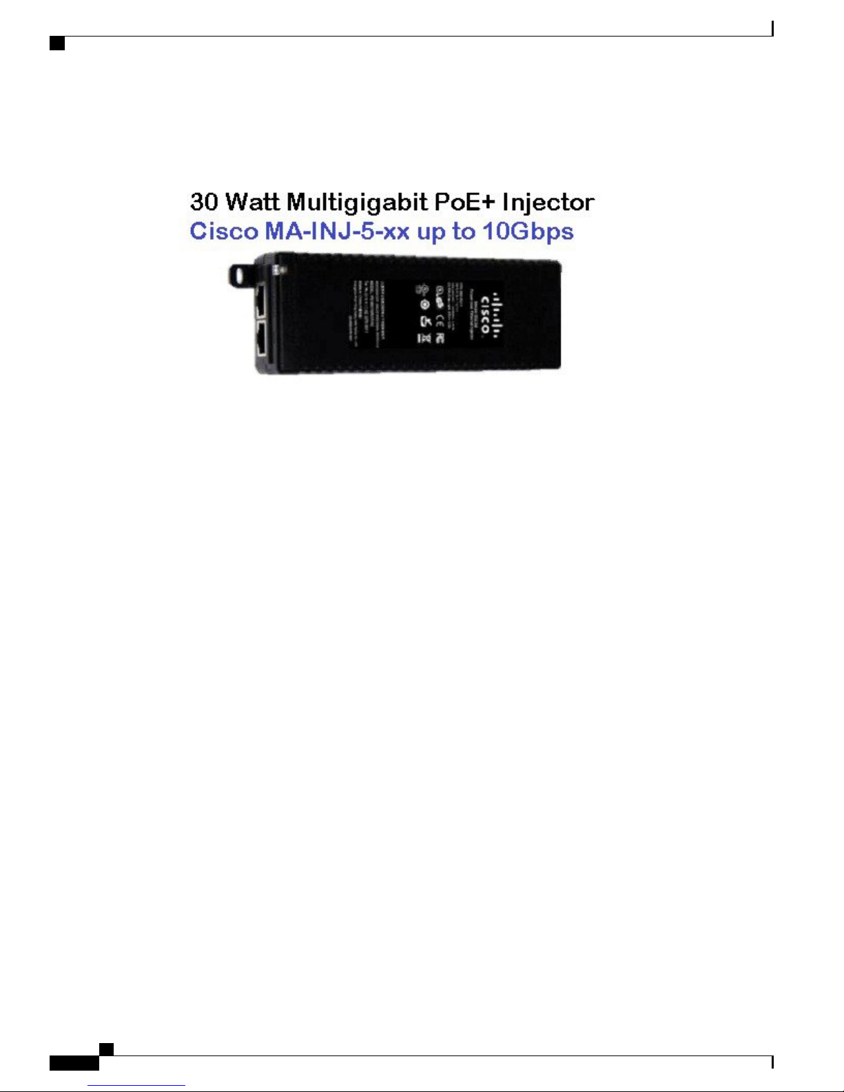
AP 2800 and AP 3800 Powering Options
An additional mid-span injector capable of 802.3bz (known as mGig / N-BASE-T).
Figure 46: Planned Mid-Span Injector
Cisco Aironet Series 2800/3800 Access Point Deployment Guide
44
Page 49

AP 2800 and AP 3800 Powering Options
Note
The Cisco AP 2800 does not support a local power supply; however the AP 3800 does have a new high
wattage supply that can be used in applications where a PoE source is unavailable.
Figure 47: White power supply and cord
Figure 48: AIR-PWR-50 mechanicals - Spare part # AIR-PWR-50=
The following Mid-Span devices are not compatible with the AP 2800 AP 3800:Note
• Mid-Span Injectors–AIR-PWRINJ, AIR-PWRINJ2, AIR-PWRINJ3, AIR-PWRINJ4 and
AIR-PWRINJ5
• Local power supplies–AIR-PWR-A, AIR-PWR-B and AIR-PWR-C
Cisco Aironet Series 2800/3800 Access Point Deployment Guide
45
Page 50

AP 2800 and AP 3800 Powering Options
Cisco Aironet Series 2800/3800 Access Point Deployment Guide
46
Page 51

CHAPTER 8
AP 3800 and Multigigabit Ethernet (mGig)
Multigigabit Ethernet (mGig), N-BASET and 802.11bz are all methods by which faster speeds can be realized
(faster than 1G) using existing infrastructure wiring such as CAT-5e. The goal is to deliver up to 5 times the
speed in the Enterprise without replacing existing cable structure.
Note
Although the AP 2800 does not directly support mGig, these are ideal switches for providing the power
required by the AP 2800 as well.
Here are the recommended mGig switches and PoE solutions for the AP 3800 .
Figure 49: Cisco line of mGig capable switches
Cisco Aironet Series 2800/3800 Access Point Deployment Guide
47
Page 52
AP 3800 and Multigigabit Ethernet (mGig)
Ideally a switch supporting IEEE 802.3bz (mGig, which is also referred to as N-BASET) will deliver the
fastest Ethernet using older cable systems such as CAT-5 and deliver +30W for newer PoE devices.
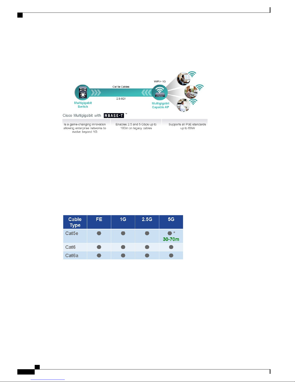
Figure 50: Cisco Multigigabit enables speeds over 1G on conventional CAT5e cable systems
In regards to cabling structure and Cisco Multigigabit Ethernet:
1
Data rates up to 1G requires 62.5–MHz bandwidth (Cat 5e is 100 MHz)
2
Data rates up to 2.5G requires 100MHz bandwidth (Cat 5e is 100 MHz)
3
Data rates up to 5G requires 200MHz bandwidth, which is more than the specified Cat 5e 100MHz
bandwidth, but within the Cat 6 cable
The main point is that 5G operations over Cat 5e may have issues using certain cable configurations due to
the fact we are using Cat 5e cable beyond the specification.
Figure 51: Cisco Multigigabit cable support at rates up to 5G
Cisco Aironet Series 2800/3800 Access Point Deployment Guide
48
Page 53

AP 3800 and Multigigabit Ethernet (mGig)
*Watch for cross-talk issues in bundles or when cables are in same pipe. Keep lengths of CAT-5e between
30-50m or below when using dense cable bundles; for example, cables in a dense area like a pipe or places
where five or more cables are tied in a bundle.
Figure 52: Cisco Multigigabit distance limitations
Figure 53: Cisco Multigigabit distance limitations
Cisco Aironet Series 2800/3800 Access Point Deployment Guide
49
Page 54

AP 3800 and Multigigabit Ethernet (mGig)
Cisco Aironet Series 2800/3800 Access Point Deployment Guide
50
Page 55
CHAPTER 9
New–B Regulatory Domain for US Theater
Recent changes in United States FCC rules requires shifting products from -A domain to -B domain effective
June 2, 2016. Access Points using -A domain can continue to operate in the US after the June deadline but
all new access points being manufactured or sold after June 2 must be -B domain.
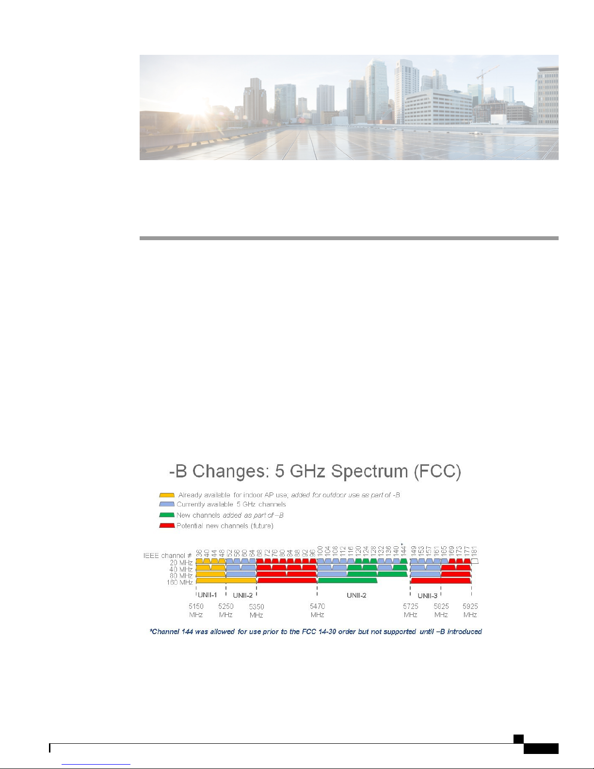
Following is a summary of new FCC rules (FCC Order 14-30) require:
U-NII 1 band (5150-5250 MHz) is now allowed for outdoor use. (+4 channels)
•
In the U-NII 1 band (5150-5250 MHz) the allowed TX power level is increased to 1W (for indoor,
•
outdoor, point to point) with extreme restrictions on EIRP above 30–degree horizon when used outdoors
The Terminal Doppler Weather Radar (TDWR) bands (channels 120, 124, 128) are re-opened with
•
new test requirements for Dynamic Frequency Selection (DFS) protection. (+3 channels)
New power spectral density and above/below band edge emissions requirements for U-NII3 (5.725-5.85
•
GHz)
Figure 54: Spectrum chart depicting new channels in the -B domain
Cisco is aggressively implementing this new FCC order:
Cisco WLAN products will comply with new FCC rules
•
Cisco Aironet Series 2800/3800 Access Point Deployment Guide
51
Page 56

New–B Regulatory Domain for US Theater
• Orderability Plans for –B domain SKU’s
Recent new AP series already support -B and are orderable; all new AP series going forward will
◦
support –B at FCS; many AP series already have –B orderable as well
◦ Sales of –A and UX SKU’s to US will start to be restricted starting May 1, 2016
• Software upgrade is required to support –B domain AP’s
◦ US customers who do not plan to deploy –B AP’s are not required to upgrade software; however,
they will need to upgrade when they plan to deploy –B AP’s after the June FCC deadline
◦ -A and -B domain AP’s can coexist in the same network without issues
• RMA’s after June deadline of a –A unit will get a –A in return
General thoughts concerning compliance as it relates to the AP 2800 and AP 3800:
• For US customers the “–B” domain is now used for AP 3800. US customers should not order the –A
domain for US based customers. Other countries that use “–A” are unchanged. This change only applies
to the US. This new “-B” domain supports the new channels and transmit powers allowed in the US.
Customers are responsible for verifying approval for use in their individual countries. To verify approval
•
that corresponds to a particular country or the regulatory domain used in a specific country, visit http:/
/www.cisco.com/go/aironet/compliance
Not all regulatory domains have been approved. As they are approved, the part numbers will be available
•
on the Global Price List.
Cisco Aironet Series 2800/3800 Access Point Deployment Guide
52
Page 57

CHAPTER 10
Stadium and Harsh Environments
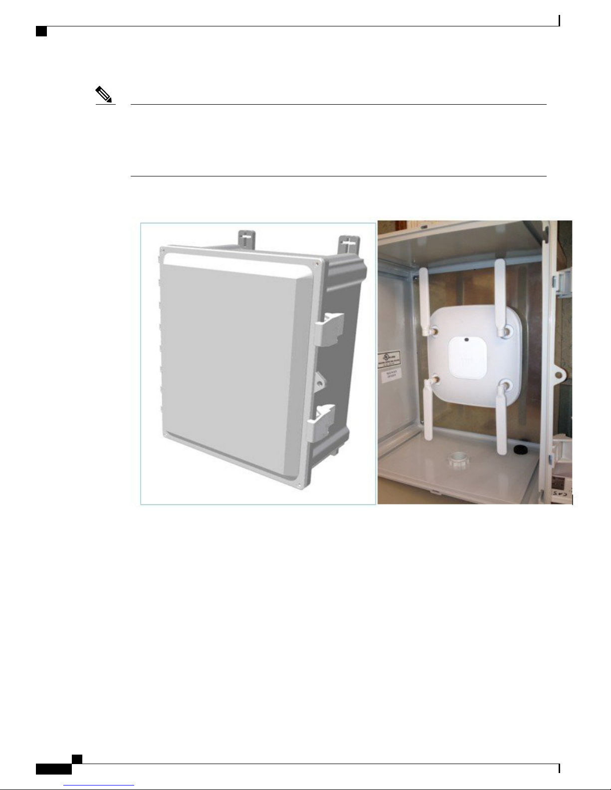
Customers wishing to install the AP in harsh environments where it may be exposed to weather, such as
stadiums, sporting areas, open garden areas or warehouse freezers, may wish to use a NEMA type enclosure.
Cisco Aironet Series 2800/3800 Access Point Deployment Guide
53
Page 58
Stadium and Harsh Environments
Note
Some access points may not be certified for outdoor deployments in a NEMA enclosure. This varies
around the world; for example, some regulatory agencies permit AP outdoor NEMA enclosures if the AP
is indoors, such as a freezer or garden area, but may prohibit its use outdoors. This seems to vary with
regard to weather radar compliance and often UNII-1 compliance. Check with your Cisco account team
or the communications regulatory agency that has jurisdiction in your part of the world.
Figure 55: Example of NEMA Enclosure with pressure vent on bottom
Third-party sources for NEMA type enclosures include:
http://www.oberonwireless.com/
http://www.sparcotech.com/
http://www.terra-wave.com/
When using a NEMA type enclosure, try to have the cables exit out of the bottom of the enclosure so that
rain and moisture do not run down the cable into the enclosure. Also, the color of the enclosure may affect
the heat rating; for example, a black enclosure gets much hotter in the sun then a white one. You may also
want to use a pressure vent to prevent moisture accumulation.
Cisco Aironet Series 2800/3800 Access Point Deployment Guide
54
Page 59
CHAPTER 11
Areas with High Vibration
If the access point is installed using a "side arm" type mount or other mounting locations where there is a
likelihood of high vibration, it is recommended that a padlock or metal pin be used to prevent the AP from
vibrating loose from the bracket.
Cisco Aironet Series 2800/3800 Access Point Deployment Guide
55
Page 60

Figure 56: Metallic Parts
Areas with High Vibration
Cisco Aironet Series 2800/3800 Access Point Deployment Guide
56
Page 61

Related References
In addition to the URLs already provided in this document, below are links to related information:
• AP 2800 Datasheet: http://www.cisco.com/c/en/us/products/wireless/aironet-2800-series-access-points/
index.html
• AP-3800 Datasheet: http://www.cisco.com/c/en/us/products/collateral/wireless/
aironet-3800-series-access-points/datasheet-c78-736498.html
Previous Deployment Guides, page 57
•
Previous Deployment Guides
• Understanding LAG and MU-MIMO: http://www.cisco.com/c/en/us/td/docs/wireless/controller/technotes/
8-1/1850_DG/b_Cisco_Aironet_Series_1850_Access_Point_Deployment_Guide.html
CHAPTER 12
Understanding Stadium, Warehouse, Factory and other RF theory such as Spatial Streams Data rates:
•
http://www.cisco.com/c/en/us/td/docs/wireless/technology/apdeploy/8-0/Cisco_Aironet_3700AP.html
Understanding mGig:
•
◦ http://blogs.cisco.com/enterprise/
introducing-cisco-catalyst-multigigabit-technology-to-future-proof-your-network-for-802-11ac-wave-2
◦ http://www.cisco.com/c/en/us/solutions/enterprise-networks/catalyst-multigigabit-switching/
index.html
◦ http://www.cisco.com/c/dam/en/us/products/collateral/switches/catalyst-4500-series-switches/
at-a-glance-c45-733656.pdf
• mGig FAQ: http://www.cisco.com/c/dam/en/us/solutions/collateral/enterprise-networks/
catalyst-multigigabit-switching/multigigabit-ethernet-technology.pdf
Cisco Aironet Series 2800/3800 Access Point Deployment Guide
57
Page 62

Previous Deployment Guides
Related References
Cisco Aironet Series 2800/3800 Access Point Deployment Guide
58
Page 63

CHAPTER 13
Frequently Asked Questions (FAQ's)
1
What are the differences between the AP 2800 and AP 3800?
The AP 3800 has the following features that are not available on the AP 2800:
mGig
•
Option module support
•
RF filters and cellular coexistence and module RF isolation
•
Local DC power connector
•
Available as optional 3800P version for outdoor and stadium applications
•
2
What are the benefits of a Flexible Radio Architecture?
Most sites have plenty of 2.4–GHz coverage, so using FRA means fewer physical APs need to be deployed
as the dual 5–GHz radios can replace installations that previously required two APs.
Flexible Radio Assignment
•
Allows for the additional XOR radio (if desired) to function similarly to a WSM module (off
◦
channel scanning) while primary 5–GHz radio services clients
◦ Reduces installation costs as a single AP can now support two 5–GHz radios (fewer APs,
better aesthetics). This can provide flexibility in architectural designs and can reduce the
number of needed Ethernet drops
Can increase accuracy of location based devices, and client can roam from Micro to Macro
◦
cell on same AP
◦ Primary 5GHz radio can service clients, while the secondary 5–GHz radio can be used to
enable testing of wider 160 MHz and/or newer channels as they become available – allowing
new features without limited performance
Allows for RF network separation (example: guest access on one radio, corporate access on
◦
the other)
•
Flexible radio, antenna, and options using integrated antenna “I” series models
One radio can be set up for HDX Micro cell and second radio setup for a Macro cell
◦
Both radios can be configured for HDX type coverage ( Micro / Micro ) cell
◦
Cisco Aironet Series 2800/3800 Access Point Deployment Guide
59
Page 64

Frequently Asked Questions (FAQ's)
• Flexible Radio / Antenna Options using external antenna “e” series models
Both radios can be setup in HDX mode for Micro cells with external antenna models
◦
Both radios can be set up in Macro cell mode with external antenna to provide two wide area
◦
cells
Different antennas can be used on each 5G radio for different coverage patterns (Omni and
◦
Directional); or one radio can serve one coverage cell while the other radio is used for a
different classroom or outdoor coverage
◦ Permits greater RF flexibility allowing XOR to combine with dedicated 5–GHz in DRE mode
(default) OR SRE mode for a 5G/5G or separate 2.4/5G or DRE 2.4 & 5G (dual band mode)
3
What is a SMART antenna connector?
The Cisco Aironet AP‐3802E, AP‐3802P, and AP‐2802E contain a SMART antenna connector, which
is connected directly to the flexible radio. Without a Smart antenna, the flexible radio must stay in 2.4GHz
only mode. Once a Smart a ntenna is connected, the flexible radio can be used in the full flexible radio
Assignment mode, allowing dual 5–GHz, wireless security monitoring, and future modes.
The Smart antenna connector can be used to connect to AIR‐CAB002‐DART‐R= which allow any
RP‐TNC based Aironet antenna to connect to the Smart Antenna port. In addition, future Smart Antennas
will be released at future times.
4
What is the Extension module slot used for?
The module slot on the AP 3802I, AP 3802E, and AP 3802P can be used to insert future modules.
Some of the proposed modules are:
3G and LTE Small Cell Offload
•
Bluetooth Beaconing (BLE)
•
Future Wi-Fi upgrades to meet new IEEE standards
•
Video Surveillance
•
Custom Applications using Linux
•
5
Why is the Extension module slot on the side?
The sidecar module architecture allows Network Engineers the ability to add/swap modules without
dismounting the access point from the mounting bracket. Additionally, it frees the optional module from
the constraints of being inside the AP.
6
What kind of plastic is AP 2800 and AP 3800 made of and is it suitable for use in hospital cleanroom
environments?
The plastic material used on the AP 2800 and AP 3800 series is Lexan 945. This material was tested for
clean room use with a Steris Chemical (trademark name SPOR-KLENZ ) http://
www.sterislifesciences.com/Products/Surface-Disinfectants-Cleaners-and-Alcohols/Sporicides-Sterilant/
Spor-Klenz-Ready-To-Use-Cold-Sterilant.aspx
7
Looking at the specification sheets, I noticed the Cisco AP 1850 supports 4x4:4 and the AP 2800/3800
supports 4x4:3. Why does the AP 1850 support one more spatial stream? How does this help me?
Cisco Aironet Series 2800/3800 Access Point Deployment Guide
60
Page 65

Frequently Asked Questions (FAQ's)
When designing the AP 2800 and AP 3800 Cisco wanted to bring the very best technology into the
device. A trade-off was made to support dual 5–GHz 160 MHz rather than the extra spatial stream, as
the additional spatial stream provides little real benefit.
In order to maintain a good 4-SS link, one needs n+1 antennas (meaning you cannot beam-form a 4-ss
client when the maximum number of antennas is 4. Additionally, there are few, if any, 4-SS clients
because the battery requirements of such a client are prohibited or limited to devices such as PCI card
or other "plugged in devices".
So while it may seem like MU-MIMO 4 spatial streams is an advantage, MU-MIMO 4 Spatial streams
seems like an advantage, MU-MIMO operation is for the most part limited to three 1-SS users or 1-SS
and one 2-SS user. The benefit is only there when you have a single 4-SS client, which is a very small
benefit.
Cisco has for years developed products using 3-SS as we use our 4thantenna to beam-form using
ClientLink to maintain a robust 3-SS signal over a greater distance than what could be reasonably
maintained without transmit beam-forming (TxBF).
Cost sensitive customers who don't require advanced features such as Cisco ClientLink, CleanAir, 160
MHz operation, FRA, mGig can certainly use the AP 1850 and gain 4-SS, but it will not outperform the
AP 2800 and AP 3800.
8
How Does AUTO-Link Aggregation (LAG) work with the AP 2800 and AP 3800?
Both the 2800 and 3800 support LAG across their primary ethernet interfaces and AUX ports. This would
provide 2Gbps of uplink to the access point. When operating in LAG, the 3800's multigigabit port will
operate as a single GE port.
The following Cisco switching series support LAG with the APs:
• Catalyst 3850 / all models (non–Converged Access mode)
• Catalyst 3650 / all models (non–Converged Access mode)
• Catalyst 4500/Sup‐8E
Catalyst 6500/Sup 720 or newer
•
9
What is ClientLink 4.0? How is it different from IEEE 802.11ac Wave-2 beam–forming?
ClientLink 4.0 is a beamforming capability built into Cisco Aironet®wireless LAN access points. When
the access point (AP) concentrates signals toward the receiving client, that client is better able to "hear"
the AP's transmission, so throughput is greater. ClientLink also enhances performance in the uplink
(client-to-AP) direction, so that the AP can also better hear the client communications. The result improves
performance in both directions.
By comparison, many competing 802.11ac-capable APs offer uplink-only enhancements, from client to
access point. Many 802.11ac-capable AP suppliers also base their downlink enhancements on the optional
transmit beamforming (TxBF) feature in 802.11ac, which requires TxCBF support in the client device
to operate.
Cisco ClientLink technology is unique in offering both uplink and downlink performance improvements,
and it does not require any special capabilities in the client device to work.
ClientLink works with all client technologies. It makes sure each client type always operates at the best
possible rate, as determined by the 802.11 access technology supported, network conditions, and the
distance of the client from the Wi-Fi AP. ClientLink helps to maintain maximum client rates.
Cisco Aironet Series 2800/3800 Access Point Deployment Guide
61
Page 66

Frequently Asked Questions (FAQ's)
10
I noticed that we can’t run 3800 with mGig and gigE ports in lag mode (without downgrading
mGig).
Correct, if you have mGig there is no need to use LAG
11
The internal antennas on the AP 2800i and AP 3800i what is the gain in dBi?
The 5 GHz Macro cell antenna is 5 dBi, the 2.4 GHz Macro Cell is 4 dBi and the XOR radio (when in
dual 5 GHz mode) uses a 6 dBi integrated antenna.
12
Is PoE only accepted on the primary port? or can I also power the device using the secondary
ethernet port?
Only the primary Ethernet port negotiates Power over Ethernet.
13
Can you advise how much system memory this access point has?
1024 MB DRAM and 256MB flash
14
I would like to understand more about FRA and how RRM works ?
Please refer the RRM guide at http://www.cisco.com/c/en/us/td/docs/wireless/controller/technotes/8-2/
b_RRM_White_Paper.html
15
Does this product support TKIP?
Customers should be discouraged from running legacy TKIP as that feature has been deprecated by the
Wi-Fi Alliance. Cisco understands there are healthcare customers using legacy equipment with a need
for TKIP support. The 1830, 1850, 2800 and 3800 does not currently support TKIP but there are plans
to support it in the 8.3MR1 release.
Cisco Aironet Series 2800/3800 Access Point Deployment Guide
62
 Loading...