

Cisco Aironet 350 series Quick Start Manual

Quick Start Guide
Cisco Aironet 350 Series Bridge
1 Take out What You Need
2 Connect and Power Up the Bridge
3 Associate an IP Address With the Br idge
4 Configure the Bridge

1 Take out What You Need
Y
S
T
I
U
V
T
I
A
T
Cisco Aironet 350 Series Bridge
LE
F
T
S
E
R
IA
L
P
O
R
T
Cisco Aironet power injector with universal
power supply, power cord, and Ethernet
cable. (optional, see the “Connect and Power
Up the Bridge” section on page 3)
Cisco Airone t Series Wireless Ac ce ss Point s
and Bridges CD with documentation, online
help files, and utilities
If any items are missing or damaged, contact your Cisc o repre sentati ve or rese ller f or suppo rt.
T
C
S
A
Y
N
T
I
O
O
I
I
V
I
D
T
T
A
A
I
C
R
C
A
O
T
S
E
S
N
A
R
E
H
T
E
T
N
I
S
E
O
I
P
ER
S
S
0
S
5
E
3
C
C
T
A
E
N
S
S
O
E
R
L
I
E
A
R
I
O
C
W
S
I
C
R
IG
H
T
/PR
IM
A
R
O
N
L
IN
E
P
A
P
T
/
O
B
R
I
D
G
E
Y
O
W
E
R
ET
H
E
R
N
E
T
K
R
O
W
T
O
E
T
N
Additonal Requirements
• An appropriate antenna for your application, a low-loss antenna cable, and a lightning arrestor
(if the antenna will be located outdoors)
• A computer that is connected to the same Ethernet network as the bridge
• A straight-through Category 5 Ethernet cable for connecting the bridge to the network
• The MAC address from the label on the bottom of the bridge (example: 00409625854c)
• The following information from your network system administrator:
–
If the bridge will not be receiving an IP address from a DHCP server, a unique IP address for
the bridge
–
The case-sensitive serv ice set identifier (SSID) for your radio network (The SSID is a unique
identifier that bridges and client devices use to associate to other bridges.)
–
If your bridge is not on the same subnet as your PC, a default gateway address and subnet
mask
• A second bridge unit if you are trying to connect two LAN segments together
2
2 Connect and Powe r Up th e Bridg e
Note Because of differences in component configuration and physical environment, every
network application is a unique installation. Therefore, before you install the bridge or other
wireless network devices, do a site survey to determine the optimum placement of these
devices to maximize range, coverage, and network performance.
Installing the Antenna
Note If you plan to use a di rectional ante nna, we reco mmend that yo u perform a car rier test
followed by an antenna alignment test to ensure optimum antenna performance. The test
procedures are described in the Cisco A ironet 35 0 Serie s Bridge Har dware Installa tion
Guide.
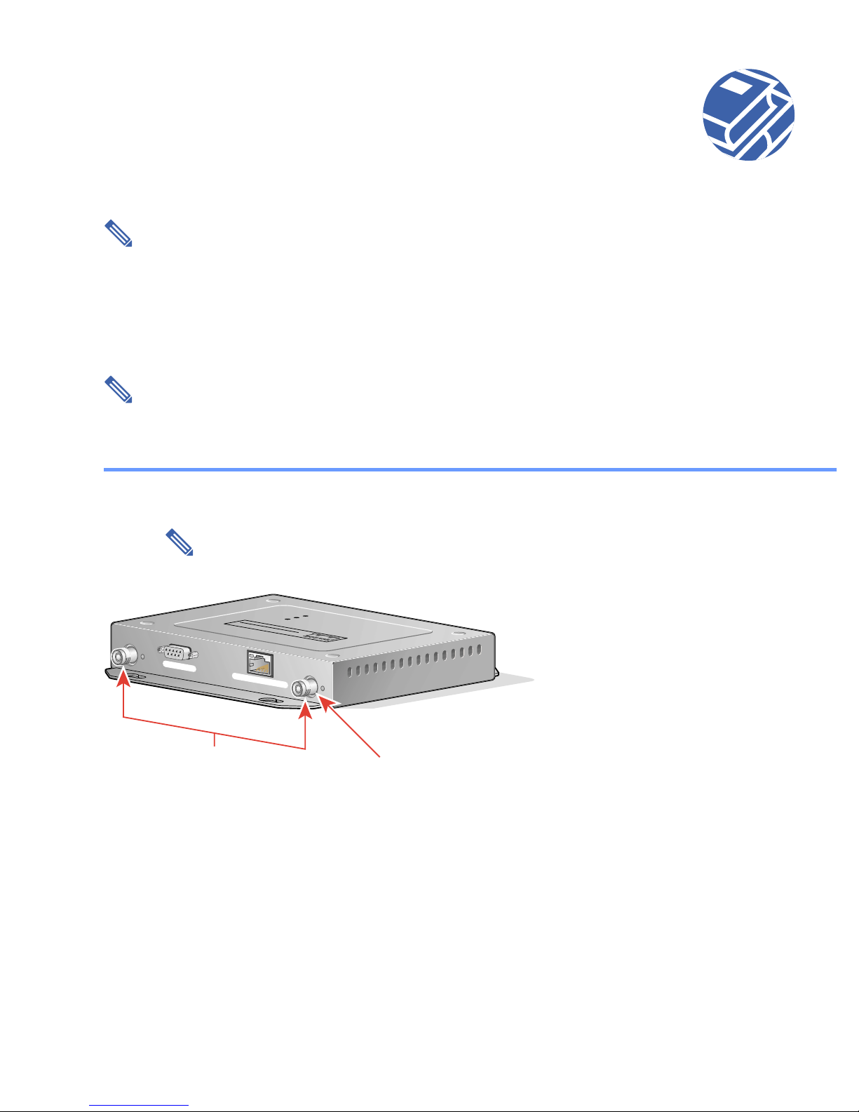
Step 1 If the antenna will be outdoors, attach a lightning arrestor to the bridge’s right antenna
connector. Refer to the mounting instructions for the lightning arrestor.
Note The lightning arrestor provides surge protection to the bridge in the event of
a nearby lightning strike and is highly recommended for outdoor use.
RADIO ACTIVITY
ASSOCIATION STATUS
ETHERNET ACTIVITY
T
IN
S
O
E
I
R
P
E
S
S
S
0
5
E
3
C
C
T
E
A
N
S
S
O
E
R
L
I
E
A
R
I
O
C
W
S
I
LEFT
SERIAL PORT
ONLINE POWER ETHERNET
Antenna
C
RIGHT/PRIMARY
Right/Primary
connectors
Step 2 Connect one end of a low-loss antenna cable to the lightning arrestor (if the antenna will be
outdoors) or to the bridge’s right antenna connector (if the antenna will be located indoors).
Step 3 Connect the other end of the antenna cable to an antenna appropriate for your application.
3
2 Connect and Power Up the Bridge (continued)
g
Step 4 Mount the antenna at an appropriate elevation to ensure maximum path clearance and
line-of-sight to another bridge or device. Refer to the documentation provided with your
antenna for mounting instructions.
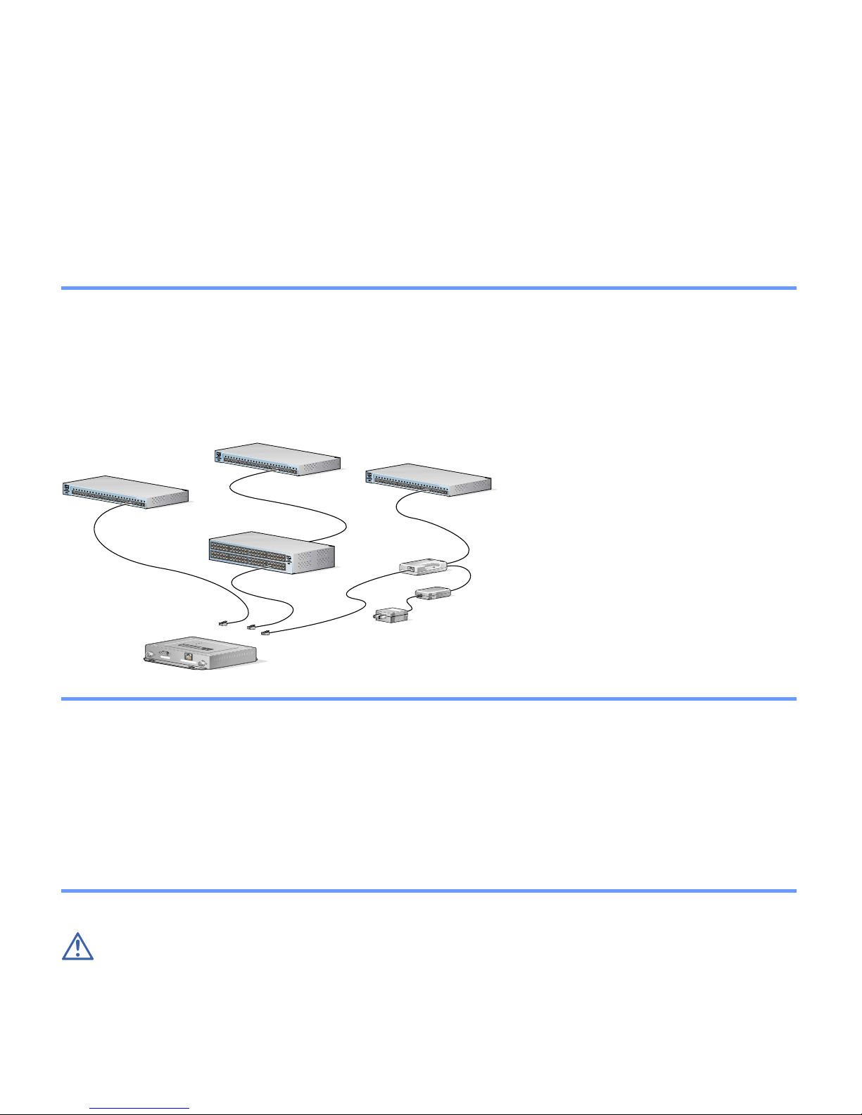
Installing the Ethernet and Power Connections
Option 1 Option 2 Option 3
Switch
S
Y
S
T
R
P
S
S
T
A
T
U
T
I
L
D
U
P
L
X
S
P
E
E
D
M
O
D
E
1
2
3
4
5
Switch with
inline power
6
7
8
1
0
B
a
s
e
-
9
T
/
1
0
0
B
a
1
s
e
0
T
X
1
1
1
2
1
3
1
4
1
5
(without inline power)
S
Y
S
T
1
R
P
S
2
3
4
S
T
A
T
5
U
T
I
L
D
U
P
L
X
6
S
P
E
E
D
7
8
1
0
B
a
s
e
-
9
T
M
/
O
1
D
0
E
0
B
a
1
s
e
0
T
X
1
1
1
2
1
3
1
4
1
5
1
6
1
7
1
8
C
a
t
a
l
y
s
1
t
9
2
9
5
0
S
E
2
R
I
0
E
S
2
1
2
2
1
2
0
3
0
B
a
s
e
F
X
2
4
2
3
2
4
1
6
1
7
1
8
C
a
t
a
l
y
s
1
t
9
2
9
5
0
S
E
2
R
I
0
E
S
2
1
2
2
1
2
0
3
0
B
a
s
e
F
X
2
4
2
3
2
4
Inline Power
Patch Panel
S
Y
S
T
R
P
S
S
T
A
T
U
T
I
L
D
U
P
L
X
S
P
E
E
D
M
O
D
E
Switch
(without inline power)
1
2
3
4
5
6
7
8
1
0
B
a
s
e
-
9
T
/
1
0
0
B
a
1
s
e
0
T
X
1
1
1
2
1
3
1
4
1
5
1
6
1
7
1
8
C
a
t
a
l
y
s
1
t
9
2
9
2
0
2
1
2
2
1
2
0
3
0
2
4
2
3
5
0
S
E
R
I
E
S
B
a
s
e
F
X
2
4
S
Y
S
T
R
P
S
S
T
A
T
U
T
I
L
D
U
P
L
X
S
P
E
E
D
M
O
D
E
Y
S
T
I
U
V
T
I
A
T
T
C
S
A
Y
N
T
O
I
I
O
I
V
I
D
T
T
A
A
I
C
R
C
A
O
T
S
E
S
N
A
R
E
H
T
E
T
N
I
S
O
E
I
P
R
E
S
S
S
0
5
E
3
C
C
T
A
E
N
S
S
O
E
R
L
I
E
A
R
I
O
C
W
S
I
L
E
F
T
C
S
E
R
I
A
L
P
O
R
T
R
I
G
H
T
/
P
R
I
M
A
R
Y
O
N
L
I
N
E
P
O
W
E
R
E
T
H
E
R
N
E
T
Brid
e
Power injector
A
P
/ B
Power
cord
T
O
R
ID
G
E
Universal
power
supply
K
R
O
W
T
E
TO
N
Step 1 Consult the drawing above and choose a power supply option.
Step 2 Connect the su pplied Ethernet cable to the Ethernet port on the back of the bridge.
Step 3 Connect the other end of the Ethernet cable to one of the following:
• A switch with inline power, such as a Cisco Catalyst 3524-PWR-XL Switch
• An inline power patch panel, such as a Cisco Catalyst Inline Power Patch Panel
• The end of a Cisco Aironet power injector labeled To AP/Bridge an d the en d la bel ed To
Network to the 10/100 Ethernet LAN.
Caution The power injector is designed for Cisco Aironet 350 series bridges and 350 series
access poin ts onl y. Using the power injec tor wi th oth er Eth erne t dev ice s can da mage the
equipment.
4
 Loading...