

Cisco Aironet 1600, Aironet 2600, Aironet 3600, Aironet 1600 Series, Aironet 2600 Series Deployment Manual
...
Cisco Aironet 1600/2600/3600 Series Access
Point Deployment Guide
Cisco Systems, Inc.
www.cisco.com

Abstract
Abstract
This document covers the theory of operation and installation for Cisco 2600 and 3600 Series Access
Points (APs), as part of a Cisco wireless LAN (WLAN) solution. Subjects include:
• AP 1600, 2600, and 3600
• Differences between the AP 3600 and the AP 3500
• Differences between the AP 3600 and the AP 2600
• Introduction of the AP 1600 and AP feature comparison
• Hardware details, mounting options, bracket choices, and installation considerations
• Antenna options, radiation patterns, and external antenna deployments
• Spatial streams and MCS rates
• ClientLink 2.0 and Bring Your Own Device (BYOD)
• Site survey considerations
• Inappropriate installations, Q&As, and useful URLs
Audience
This document is intended for trained and experienced technical personnel familiar with the existing
Cisco Wireless Networking Group (WNG) product line and features.
Revision History
Document Number: EDCS-1188900
Document Author: Frederick Niehaus
Author's Organization: WNG (WNBU) TME
Document Date / Version: 12/12/12 version 3.0
Table of Contents
• Revision History
• Cisco Aironet Series Access Points
• Cisco Aironet Series Access Points
(replaces
EDCS-1130881)
(fredn)
–
Internal and External Antennas
–
3600 Series
• Feature Modules for the 3600 Series
Cisco Aironet 1600/2600/3600 Series Access Point Deployment Guide
2

–
Comparison of the 3600 and 3500 Series
–
Comparison of the 3600 and 2600 Series
–
Introduction to the 1600 Series
• Key Features
• Cisco CleanAir Express
–
Comparison of Indoor Access Points
• Hardware and Mounting Options
–
Brackets and Clips
–
Channel Rail Adapters
–
Installation in Ceiling Tiles
–
Installation on Walls
–
Color
• Unique Installations
–
Clean Rooms
–
Above Ceiling Tiles
–
Stadium and Harsh Environments
–
Areas with High Vibration
Table of Contents
–
Warehouse and Factory
• Ethernet Cable Recommendation
• Antenna Cable Recommendation
• Access Point Spacing Recommendations
–
IDF Closets (Telecommunications or Other Electrical Equipment)
–
Very High Altitudes
–
Common or Distributed Antenna System (DAS)
–
Elevators
• External Antenna Options and Patterns
–
AP 1600/2600 and AP 3600e
–
AP 3600i, AP 2600i, and AP 1600i
• External Antenna Deployments
• 802.11n, Spatial Streams, and Beamforming
–
Clients That Support Three Spatial Streams
–
Beamforming in ClientLink 1.0 and 2.0
• Site Survey Considerations
• General Guidelines
• Examples of Improper Installations
• Questions and Answers
• Useful URLs
Cisco Aironet 1600/2600/3600 Series Access Point Deployment Guide
3
Cisco Aironet Series Access Points
Cisco Aironet Series Access Points
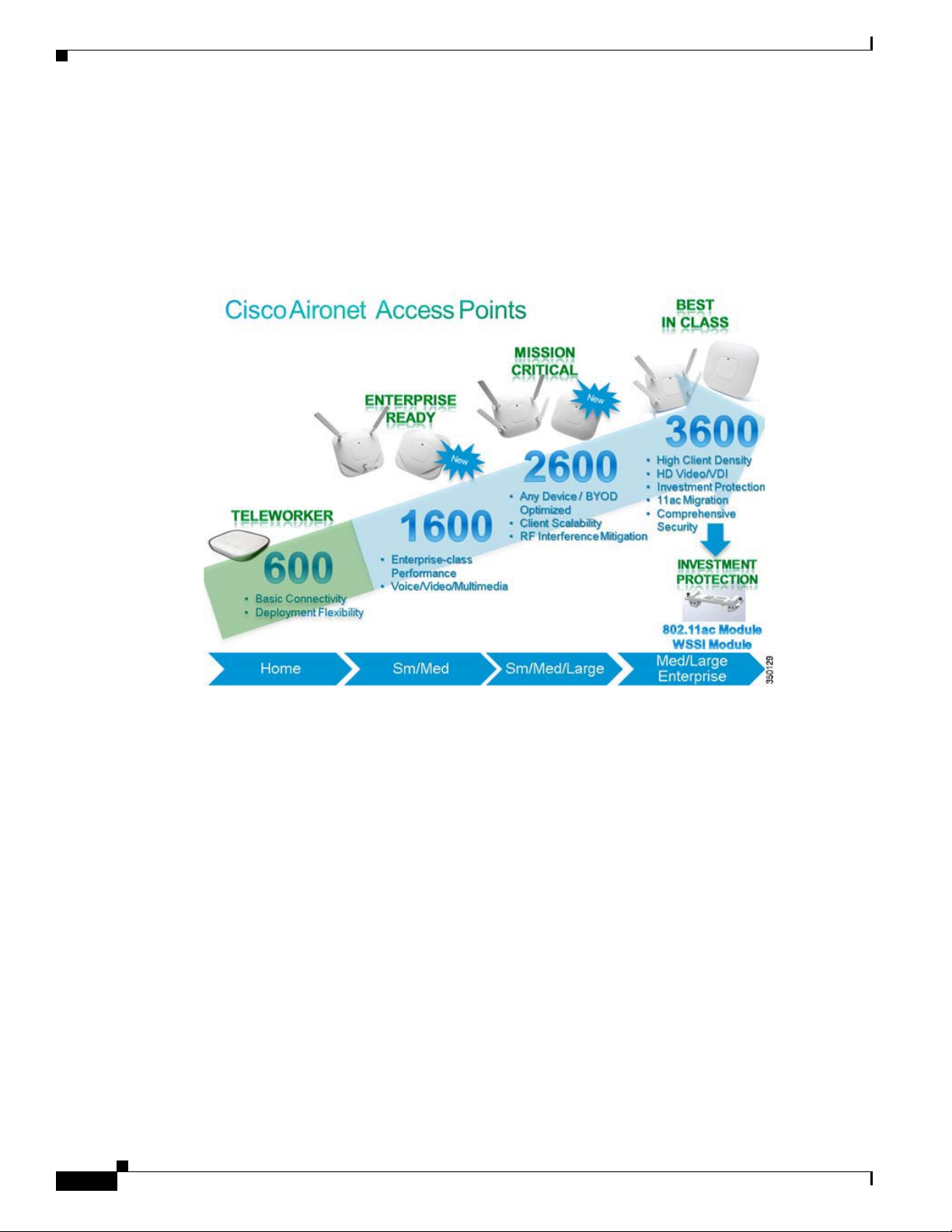
Cisco Aironet 3600, 2600, 1600, and 600 Series Access Points (APs) provide highly secure and reliable
wireless connections for both indoor and outdoor environments. Figure 1 illustrates the product
portfolio, which ranges from the entry-level 600 Series for basic connectivity to the 3600 Series for
best-in-class performance.
Figure 1 Access Point Portfolio Placement
Internal and External Antennas
The 3600, 2600, and 1600 Series offer models with internal or external antennas. Figure 2, Figure 3, and
Figure 4
describe the internal and external antenna models for each series.
• APs with internal antennas have an “i” (for example, AP 3600i) in the model number. They have
captured antennas, which are part of the housing and not removable, and are designed for indoor
enterprise installations where office aesthetics are a primary concern.
• APs with external antennas have an “e” (for example, AP 3600e) in the model number. They are
more rugged and are designed for industrial use in locations such as hospitals, factories, warehouses,
and other locations where there is a need for external antennas or extended operating temperatures.
The external antenna models also support mounting inside NEMA enclosures for use in the most
demanding environments.
Cisco Aironet 1600/2600/3600 Series Access Point Deployment Guide
4
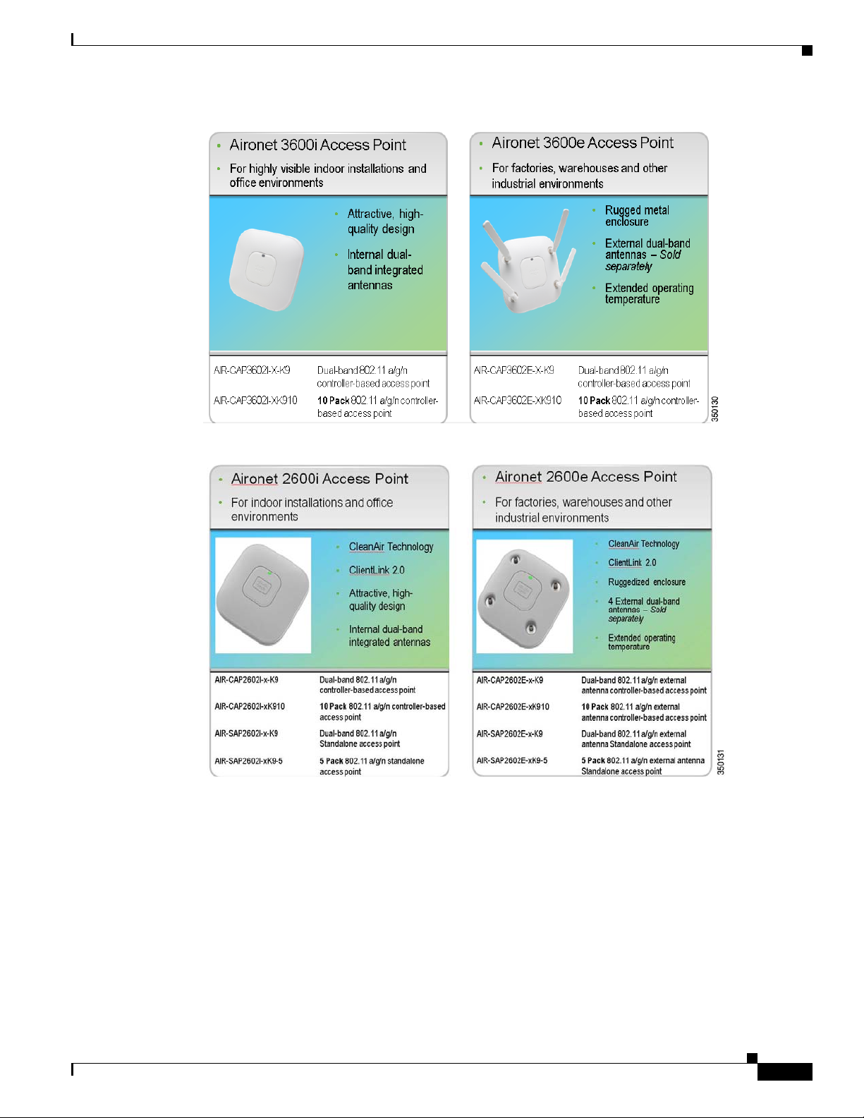
Figure 2 AP 3600 Models and Eco-Packs
Figure 3 AP 2600 Models and Eco-Packs
Cisco Aironet Series Access Points
Cisco Aironet 1600/2600/3600 Series Access Point Deployment Guide
5
Cisco Aironet Series Access Points
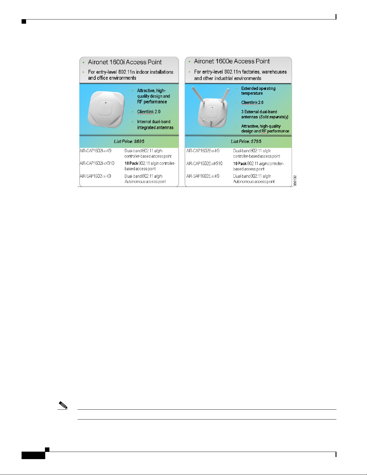
Figure 4 AP 1600 Models and Eco-Packs
3600 Series
The Cisco 3600 Series Access Point (AP 3600) targets customers who require support for
mission-critical applications. The AP 3600 embodies ClientLink 2.0, an innovative antenna technology
comprising four transmit radios and four receive radios called 4X4 Multiple Input Multiple Output
(MIMO) and three spatial stream (3SS) beamforming, together referenced as 4x4:3. ClientLink 2.0
permits speeds up to 450 Mbps via additional Modulation and Coding Scheme (MCS) data rates 16-23,
while still maintaining IEEE 802.3af (15.4 Watt) Power over Ethernet (PoE) compliance. See the section
on "802.11n, Spatial Streams, and Beamforming" for more on spatial streams.
Feature Modules for the 3600 Series
The WSSI (Wireless Security and Spread Spectrum Intelligence) module adds new functionalty to the
AP 3600 to protect customer investment. This optional, add-on module provides a dedicated monitor
radio to scan the full spectrum, not just the channel on which the AP operates. It offloads complete
monitoring and security services to the monitor module, including CleanAir, WIDS/WIPS,
Context-Aware Location, Rogue Detection, and Radio Resource Management (RRM). The WSSI
module allows for full spectrum analysis on all channels on both the 2.4 and 5 GHz bands. It avoids the
need to deploy a separate, dedicated overlay network for full spectrum monitoring and eliminates the
need for an extra cable pull and additional infrastructure costs.
The second available module provides 802.11ac (wave-1) functionality to the AP 3600. This radio
module operates at 5GHz and allows the AP 3600 to fully support 802.11a/n along with 802.11ac clients.
(Wave-1) functionality supports a 1.3 Gbps PHY / ~1 Gbps MAC (throughput) using three spatial
streams, 80 MHz, 256 QAM. It also supports Explicit Beamforming per the 802.11ac standard. Use of
the radio module may require a local power supply, Cisco power injector, .3at PoE+, or use of the Cisco
Enhanced PoE because the module may draw power greater than 15.4W.
Note Cisco Enhanced PoE was created by Cisco and is the forerunner to 802.3at PoE+.
Cisco Aironet 1600/2600/3600 Series Access Point Deployment Guide
6
Cisco Aironet Series Access Points
Feature modules slide into the bottom of AP 3600, as shown in Figure 5.
Figure 5 Back View of the AP 3600 with Feature Module
Note Please refer to the Installing the Module section of the Installing the Cisco Aironet 3600 Series Access
Point 802.11ac Radio Module guide for more details.
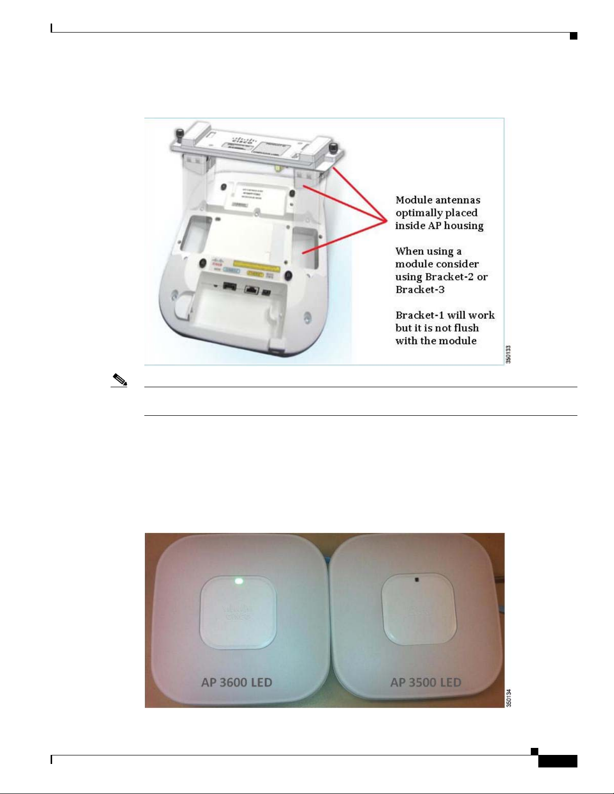
Comparison of the 3600 and 3500 Series
The AP 3600i (internal antenna model) and the Cisco 3500 Series Access Point (AP 3500) are almost
identical in physical appearance. To easily distinguish them, note that the LED for the AP 3500 is square,
while the AP 3600i has an LED that is slightly larger and more oval. (See Figure 6.)
Figure 6 LED Appearance in the AP 3600i and the AP 3500
Cisco Aironet 1600/2600/3600 Series Access Point Deployment Guide
7
Cisco Aironet Series Access Points
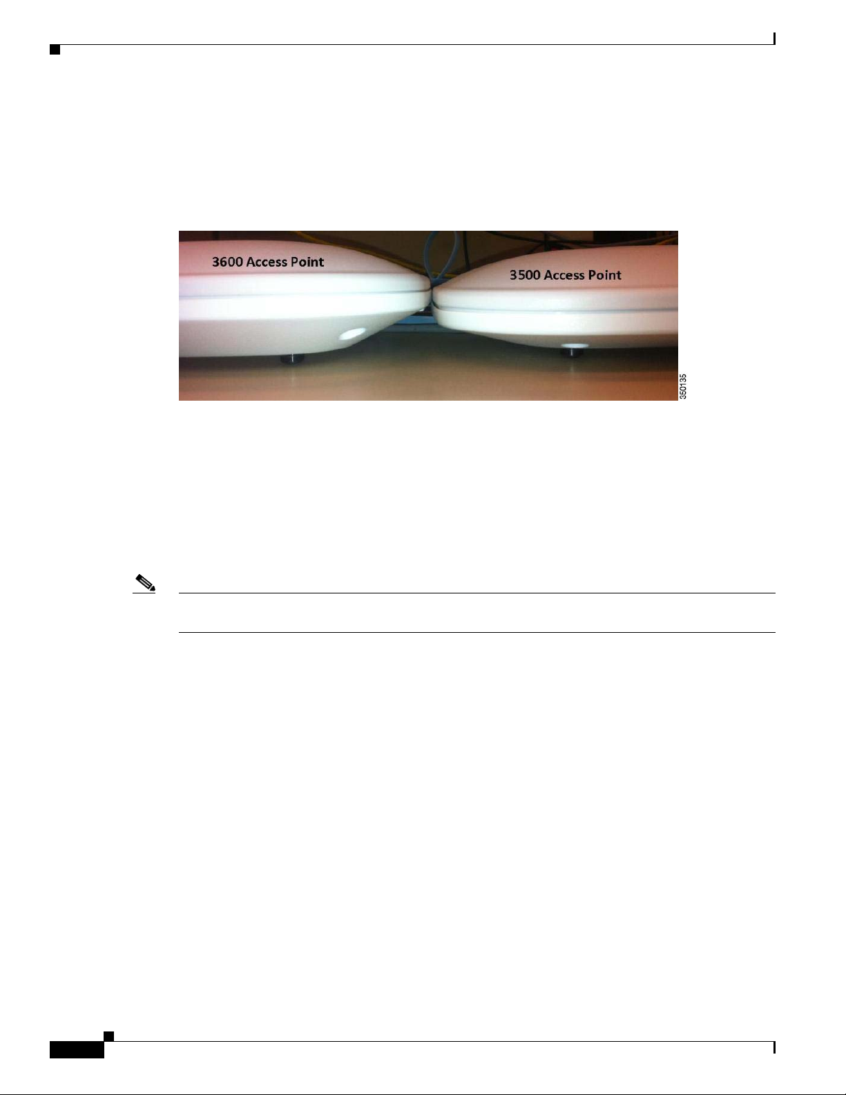
From a side view, the AP 3600i is slightly thicker (2.11”) than the AP 3500 (1.84”), as shown in Figure 7.
The thicker size allows for additional radio support and printed circuit board area, as well as feature
modules for future capabilities. While the AP 3600i has a little more depth, it is completely backward
compatible with the mounting brackets for the existing Cisco Aironet 1040 Series Access Point (AP
1040), 1140 Series Access Point (AP 1140), 1260 Series Access Point (AP 1260), and the AP 3500.
Figure 7 Side View of the AP 3600i and the AP 3500
The external antenna models (the AP 3600e and the AP 3500e) differ in appearance because the AP
3600e has fewer antenna connector ports, primarily due to the dual-band antenna system.
The AP 3600e has combined all the antenna ports (dual-band) so that each antenna port can transmit
simultaneously on each band; if the antenna ports were not combined, this would have required eight
antennas. The AP 3600 has four transceivers (transmitter/receiver) radio ports per band for a total of
eight transceivers, four in each band. This additional radio per band permits beamforming to 3SS clients
using ClientLink 2.0 to improve the overall performance of all 802.11n clients with one, two, and three
spatial streams.
Note Beamforming to a 3SS client requires n+1 radio frequency (RF) design. To accomplish this, the AP 3600
has an additional radio per band, which improves client performance by using Cisco ClientLink 2.0.
The AP 3500e has separate antennas for each band, 2.4 GHz and 5 GHz, and does not support 3SS
technology, since it has only two transceivers (transmitter/receiver) and one extra receiver per band
enabling operation up to two spatial streams.
Unlike the AP 3500, the newer AP 3600 design supports an optional, add-on feature module. The bottom
of the AP 3600 has openings to support the feature module, as shown in Figure 8. The openings, while
fully sealed, permit the module to have access to the top of the AP, which allows the module antennas
(if present) to fully function. The unit includes a positive snap “spring loaded BB” so the installer can
feel a positive lock when the AP is fully engaged in the bracket.
Cisco Aironet 1600/2600/3600 Series Access Point Deployment Guide
8
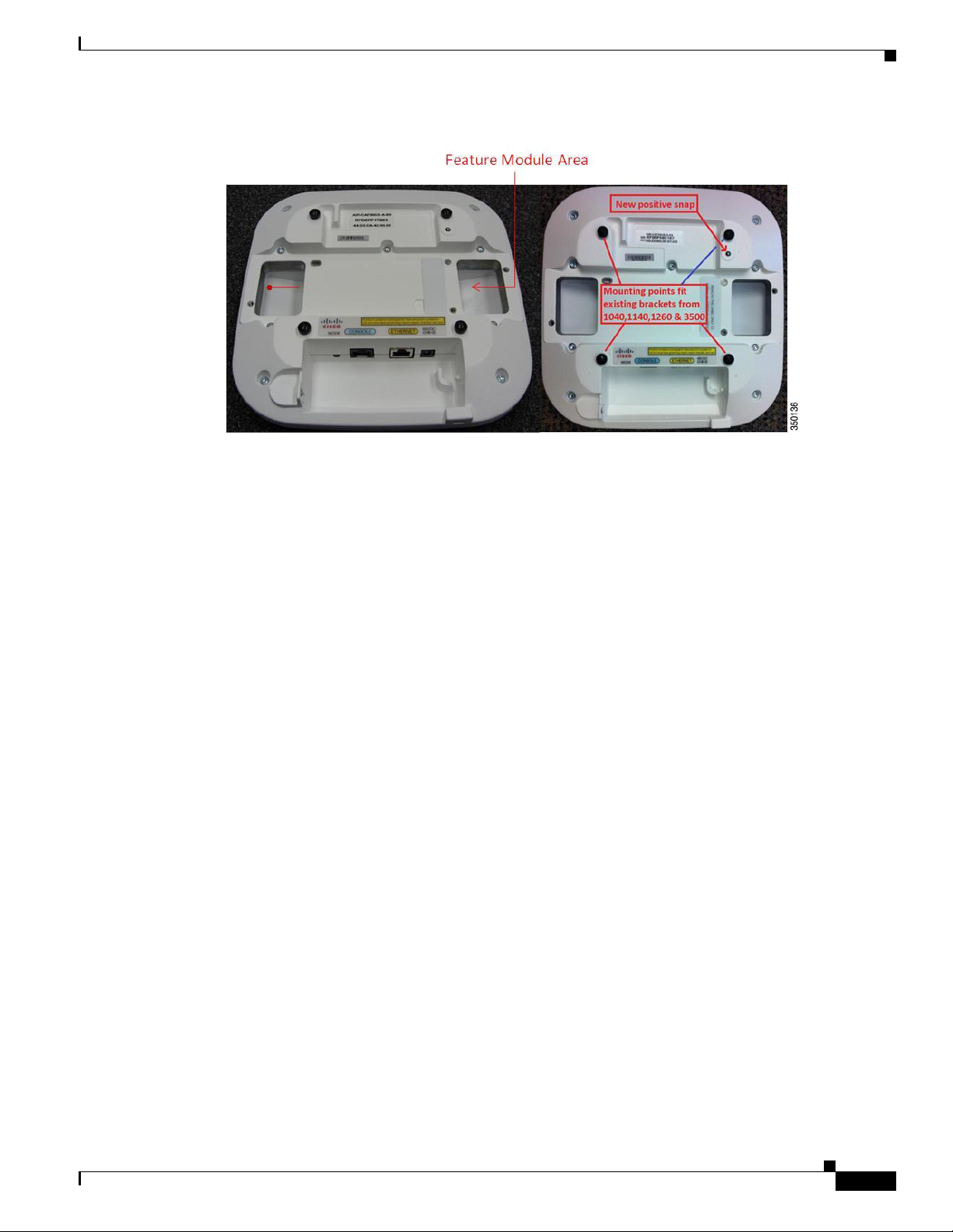
Figure 8 Bottom View of the AP 3600 with Support for a Feature Module
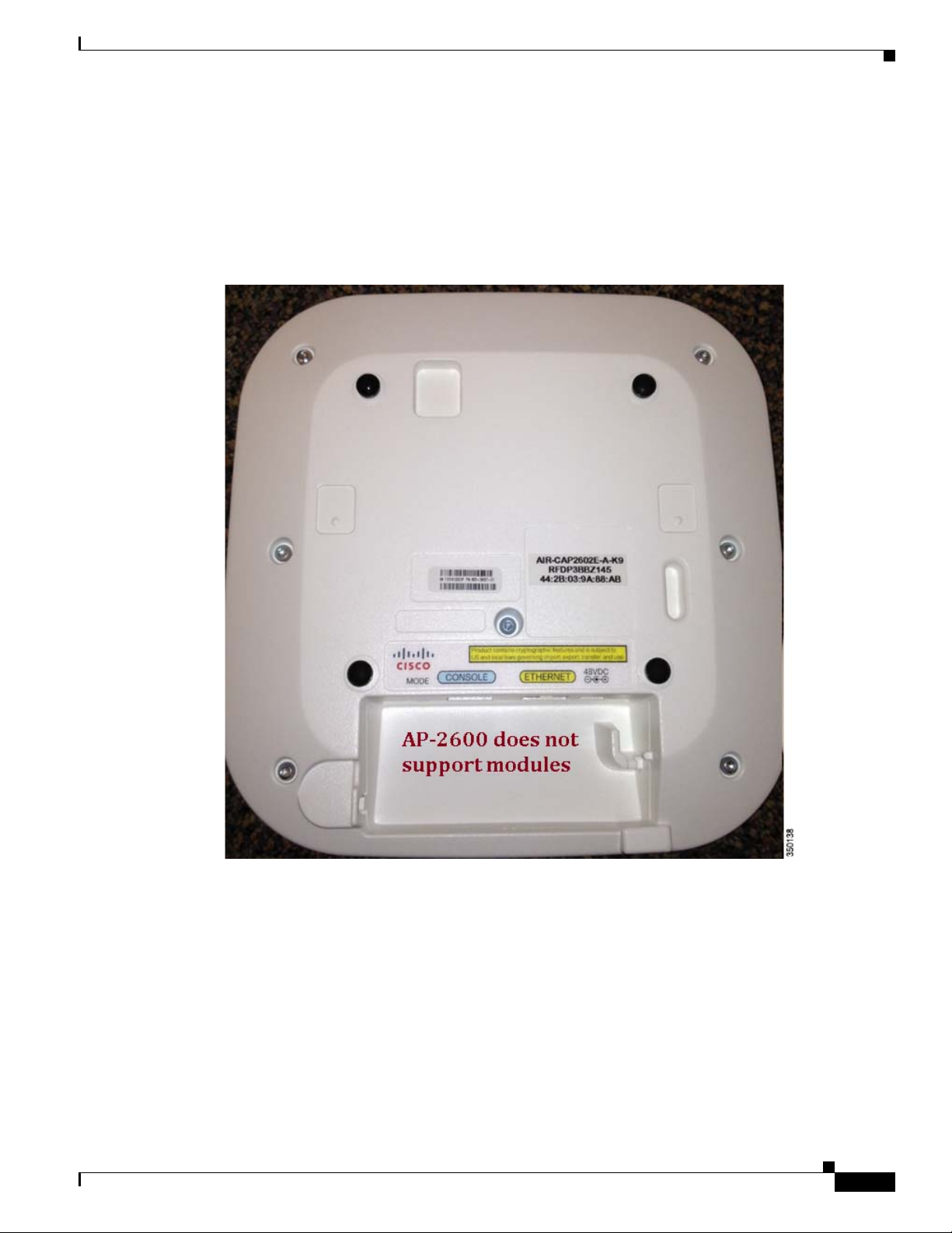
Comparison of the 3600 and 2600 Series
Cisco Aironet Series Access Points
The AP 3600 has a modular design that offers future protection with optional .11ac and security
modules. The AP 2600 does not support optional modules. However, the AP 2600 does have a slightly
higher antenna gain in the 2.4 GHz band.
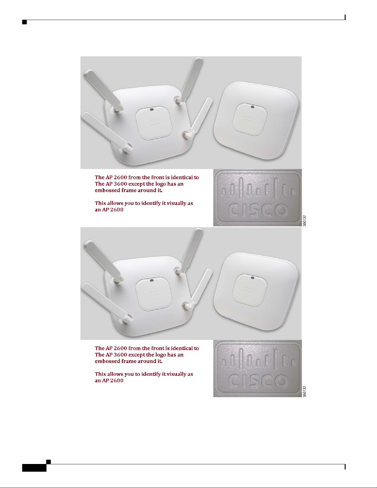
The AP3600 and the AP2600 are the same size, but it is easy to identify each one by noting whether the
Cisco logo has an embossed frame (AP 3600) or not (AP 2600). (See Figure 9.)
Cisco Aironet 1600/2600/3600 Series Access Point Deployment Guide
9
Cisco Aironet Series Access Points
Figure 9 Front View of the AP2600 and the AP 3600
10
Cisco Aironet 1600/2600/3600 Series Access Point Deployment Guide
Cisco Aironet Series Access Points
The AP 2600 is a 3X4:3SS, so ClientLink does not beamform to 3SS clients; however, it does beamform
at legacy, one, and two spatial stream rates. The AP 3600 is a 4X4:3SS, supporting an extra transmitter
chain for additional downlink performance for all bands and clients. The AP 3600 has slightly higher
performance and beamforms to legacy, one, two, and three spatial stream rates and .11ac rates when
using the optional .11ac module.
The two series use the same mounting hardware and antennas. See Figure 10 for a back view.
Figure 10 Back View of the AP 2600
Because of these similarities, there is no need to repeat a site survey for the AP 2600 if a survey exists
for the AP 3600.
Cisco Aironet 1600/2600/3600 Series Access Point Deployment Guide
11
Cisco Aironet Series Access Points
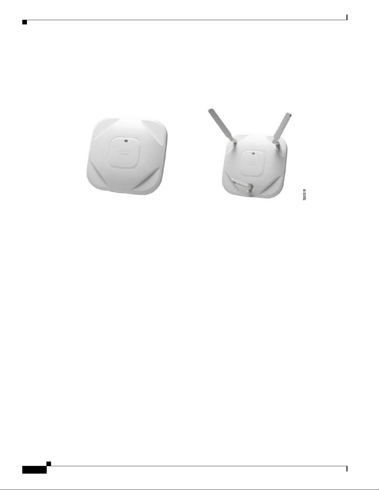
Introduction to the 1600 Series
The Cisco Aironet 1600 Series Access Point (AP1600), shown in Figure 11, is a second generation,
entry-level AP.
Figure 11 AP 1600
Key Features
Significant features include:
• ClientLink 2.0
–
–
–
–
• 3x3:2 architecture
–
–
• External antenna model for entry-level and mid-level market
• Up to 128 clients per radio for a total of 256 clients
• Different LED color change compared to earlier access points
• CleanAir Express – Basic Spectrum Analysis available soon via software upgrade
Cisco CleanAir Express
Cisco CleanAir Express technology is enabled on the advanced silicon design of the AP 1600. With
CleanAir Express, the AP 1600 has the ability to effectively detect RF interference, identify the source,
locate it on a map, and make automatic adjustments to optimize wireless coverage. With CleanAir
Express technology, organizations have a basic spectrum analysis capability to support their wireless
networks while simplifying ongoing operations. (See Figure 12.)
Adds a key function when upgrading from the AP 1040/1140 and the AP 1260
Supports 802.11n clients up to 1-SS
Supports 802.11a/b/g clients
Supports (beam-form) up to 32 clients per radio interface
Better performance than the 2x2:2 AP 1040
Better throughput performance than the AP 1140 and the AP 1260
12
Cisco Aironet 1600/2600/3600 Series Access Point Deployment Guide
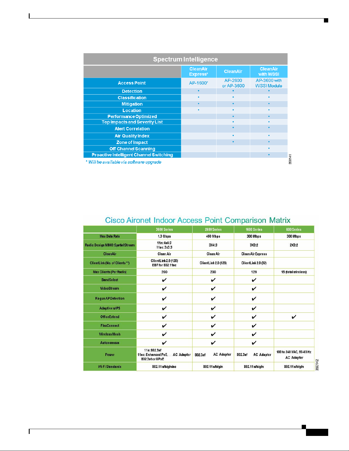
Figure 12 Comparison of CleanAir Features in the 1600/2600/3600 Series
Comparison of Indoor Access Points
Cisco Aironet Series Access Points
A comparison of the indoor access points for the 3600/2600/1600/600 Series is shown in Figure 13.
Figure 13 Comparison of the 3600/2600/1600/600 Series
Cisco Aironet 1600/2600/3600 Series Access Point Deployment Guide
13
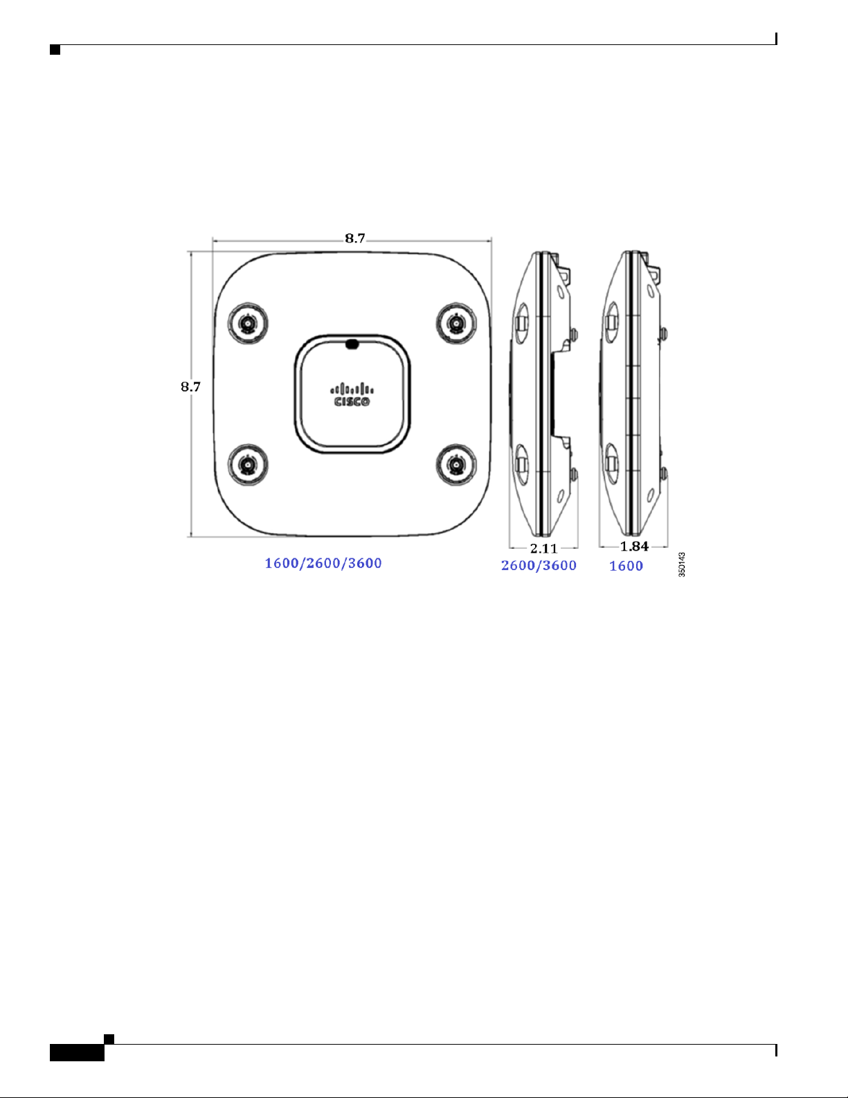
Hardware and Mounting Options
Hardware and Mounting Options
The AP 1600, 2600, and 3600 have the same mounting options and share similar dimensions, as shown
in Figure 14. There are slight cosmetic differences; for example, there are three antennas on the AP 1600.
Figure 14 Mechanical Drawing of the AP 2600 and the AP 3600
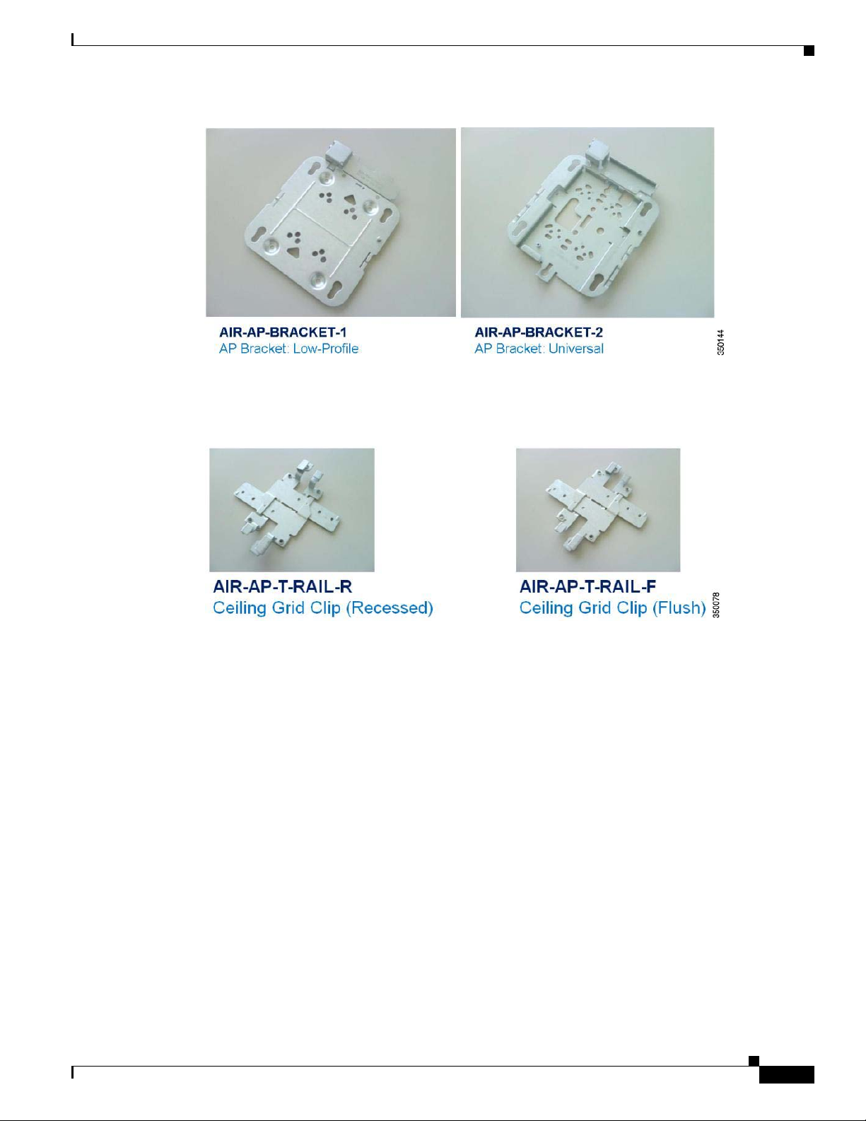
Brackets and Clips
There are many different installation options available depending upon the requirements of the customer.
Brackets are available from Cisco as well as third-party companies. When ordering, the customer may
choose either a low-profile or a universal bracket; both are shown in Figure 15. Each bracket is a
zero-dollar ($0) option at the time of configuration.
If the customer does not choose a bracket, the default is the low-profile AIR-AP-BRACKET-1, which is
the most popular bracket for ceiling installations. For the AP 3600, Cisco recommends using the
universal bracket, part number AIR-AP-BRACKET-2.
14
Cisco Aironet 1600/2600/3600 Series Access Point Deployment Guide
Hardware and Mounting Options
Figure 15 Access Point Bracket Choices
If the AP needs to be mounted directly to a ceiling on the gridwork, AIR-AP-BRACKET-1 mounts flush
and has the lowest profile. Since some ceiling tiles are recessed, two different styles of ceiling clips,
recessed and flush rails, are available to mount the bracket to the ceiling gridwork. (See Figure 16).
Figure 16 Recessed and Flushed Ceiling Grid Clips
If the AP needs to be mounted to an electrical box, to another type of wiring fixture, inside a NEMA
enclosure or on a wall, the AIR-AP-BRACKET-2 is a better choice. The extra space in the bracket allows
for wiring, and the extra holes line up with many popular electrical boxes.
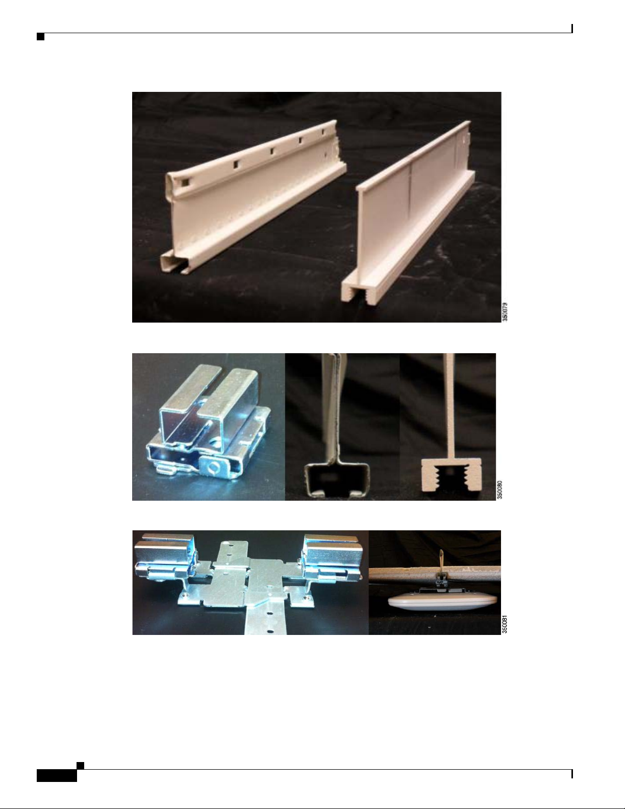
Channel Rail Adapters
When mounting APs to ceiling channel rails, such as those shown in Figure 17, use the optional channel
adapter. The AIR-CHNL-ADAPTER comes in a two-pack, slides onto the channel rails, and attaches to
the ceiling grid clips described above. Figure 18 and Figure 19 show the channel rails, channel adapter,
ceiling grid clip, and finished installation.
Cisco Aironet 1600/2600/3600 Series Access Point Deployment Guide
15
Hardware and Mounting Options
Figure 17 Channel Rails
Figure 18 AIR-CHNL-ADAPTER (left); Channel Rails (right)
Figure 19 AIR-CHNL-ADAPTER and Ceiling Grid Clip (left); Finished Installation (right)
16
Cisco Aironet 1600/2600/3600 Series Access Point Deployment Guide
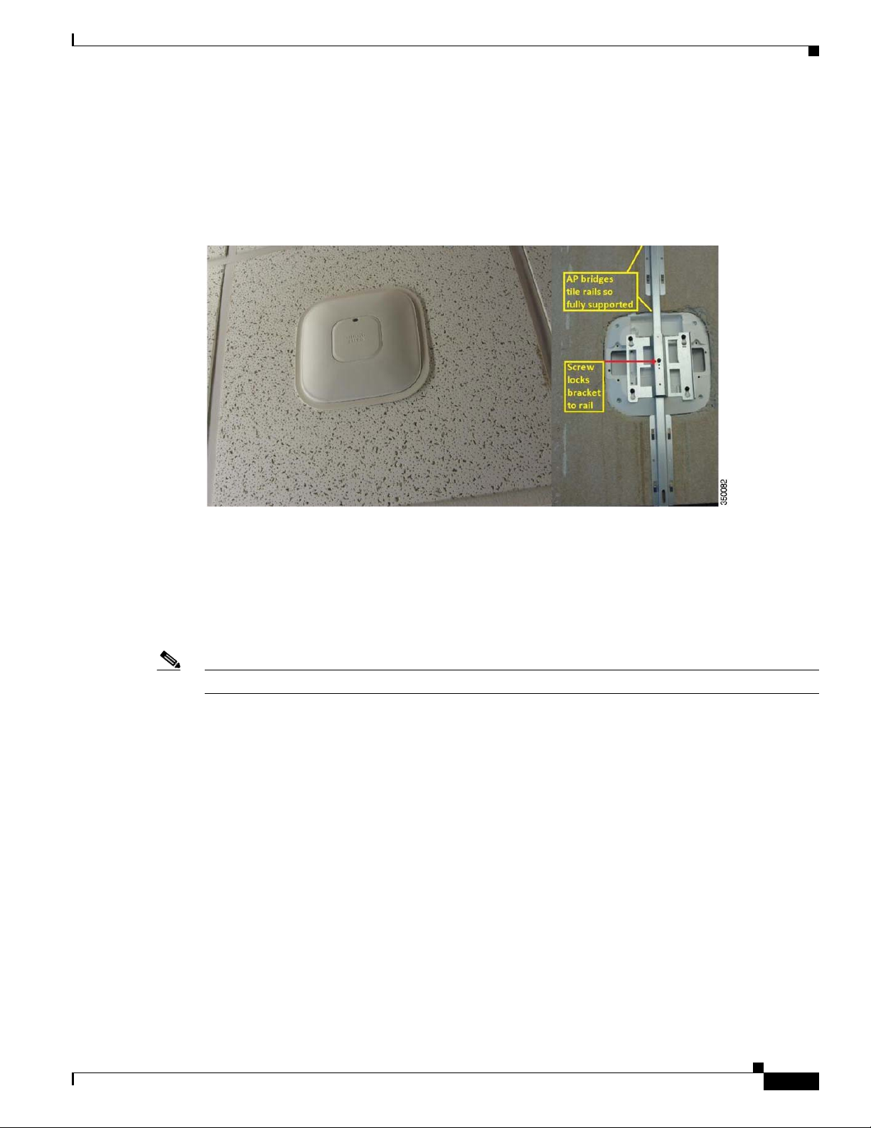
Installation in Ceiling Tiles
Many hospitals and other carpeted enterprise environments prefer a more streamlined look and wish to
install the AP directly into the tile. In this case, use the optional Cisco AIR-AP-BRACKET-3, as shown
in Figure 20.
Figure 20 Optional AIR-AP-BRACKET-3 for Installation of APs into Ceiling Tiles
Hardware and Mounting Options
Use the “beauty ring” as a template to cut the tile. Cisco does not offer custom cut tiles but the tiles are
easy to cut with a carpet knife or electric tool such as the Dremel™ or Rotozip™ rotary cutting tool.
A metal rail that extends the length of the tile supports the AP above the ceiling if the tile becomes wet
or otherwise fails. A mechanical set screw pulls the AP tight to the ceiling and locks it into the bracket.
Additionally, a Kensington style lock can be used for physical security of the AP, but, once installed, it
is difficult to remove the AP without removing the tile since the AP does not slide out from the front side
of the tile.
Note This bracket fits the AP 1040, 1140, 1260, 1600, 2600, 3500, and 3600.
Installation on Walls
Walls can be a physical obstacle to the wireless signal and may compromise 360 degree coverage. If the
wall is an outside wall or if the goal is to send the signal in a 180-degree pattern rather than a 360-degree
pattern, a directional antenna (often referred to as a patch antenna) used with the AP 3600e may be a
better choice.
Avoid wall-mounting APs with internal antennas such as the AP 3600i. The internal antenna model is
designed to mount to a ceiling to provide 360-degree coverage. If wall-mounted in a non-horizontal
orientation, the signal may penetrate floors and ceilings. This causes unintended coverage and may result
in additional, needless roaming access when, for example, a user with Wi-Fi phone walks on an adjacent
floor.
Cisco Aironet 1600/2600/3600 Series Access Point Deployment Guide
17
 Loading...