

Page 1
Installing Antennas
351321
1
3
4
2
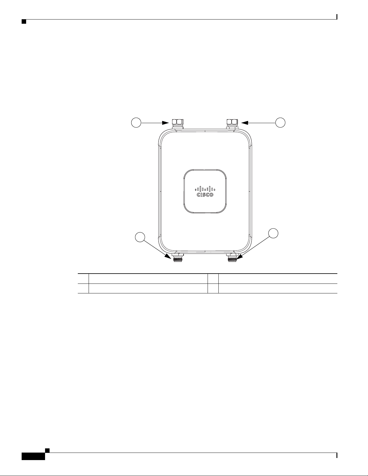
Antenna N-Type Connector Locations
The access point antenna N-type connectors are located on the top and the bottom of model
AIR-CAP1532E-x-K9. The N-type connectors support variety of the Cisco Aironet antennas. For
detailed information on these antennas, refer to Antenna Configurations, page 2-29. Figure 2-23 shows
the antenna port locations viewed from the RF cover side.
Figure 2-23 Antenna Port Locations - Model AIR-CAP1532E-x-K9
Chapter 2 Installing the Access Point
1 Antenna port 1 – Type N connector 2 Antenna port 2- Type N connector
3 Antenna port 3– Type N connector (with cap) 4 Antenna port 4- Type N connector (with cap)
Installing a Lightning Arrestor
Overvoltage transients can be created through lightning static discharges, switch processes, direct
Installation Considerations
Cisco Aironet 1530 Series Outdoor Access Point Hardware Installation Guide
2-38
contact with power lines, or through earth currents. The Cisco Aironet AIR-ACC245LA-N Lightning
Arrestor limits the amplitude and duration of disturbing interference voltages and improves the over
voltage resistance of in-line equipment, systems, and components. A lightning arrestor installed
according to these mounting instructions balances the voltage potential, thus preventing inductive
interference to parallel signal lines within the protected system.
Cisco recommends that you bulkhead mount the lightning arrestor so it can be installed as a wall-feed
through on the wall of the protected space.
The importance of obtaining a good ground and bonding connection cannot be overstressed. Consider
these points when grounding the lightning arrestor:
OL-30864-01
Page 2
Chapter 2 Installing the Access Point
1
2
3
4
5
346382
• Connect the lightning arrestor components directly to the grounding point.
• The contact points of the ground connection must be clean and free of dust and moisture.
• Tighten threaded contacts to the torque specified by the manufacturer.
Installation Notes
This lightning arrestor is designed to be installed between the antenna cable that is attached to an outdoor
antenna and the Cisco Aironet wireless device. You can install the lightning arrestor either indoors or
outdoors. It can be connected directly to a wireless device having an external N connector. It can also be
mounted inline or as a feed-through. Feed-through installations require 5/8 in. (16 mm) hole to
accommodate the lightning arrestor.
Note This lightning arrestor is part of a lightning arrestor kit. The kit contains a lightning arrestor and a
grounding lug.
Note When you install the lightning arrestor, follow the regulations or best practices applicable to lightning
protection installation in your local area.
Installing Antennas
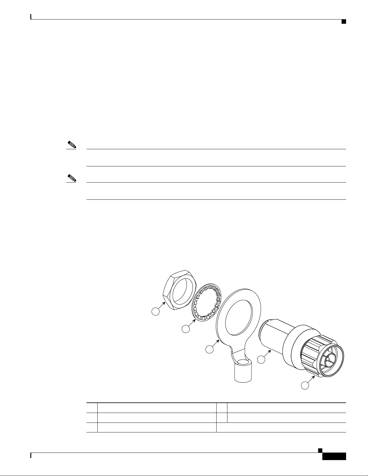
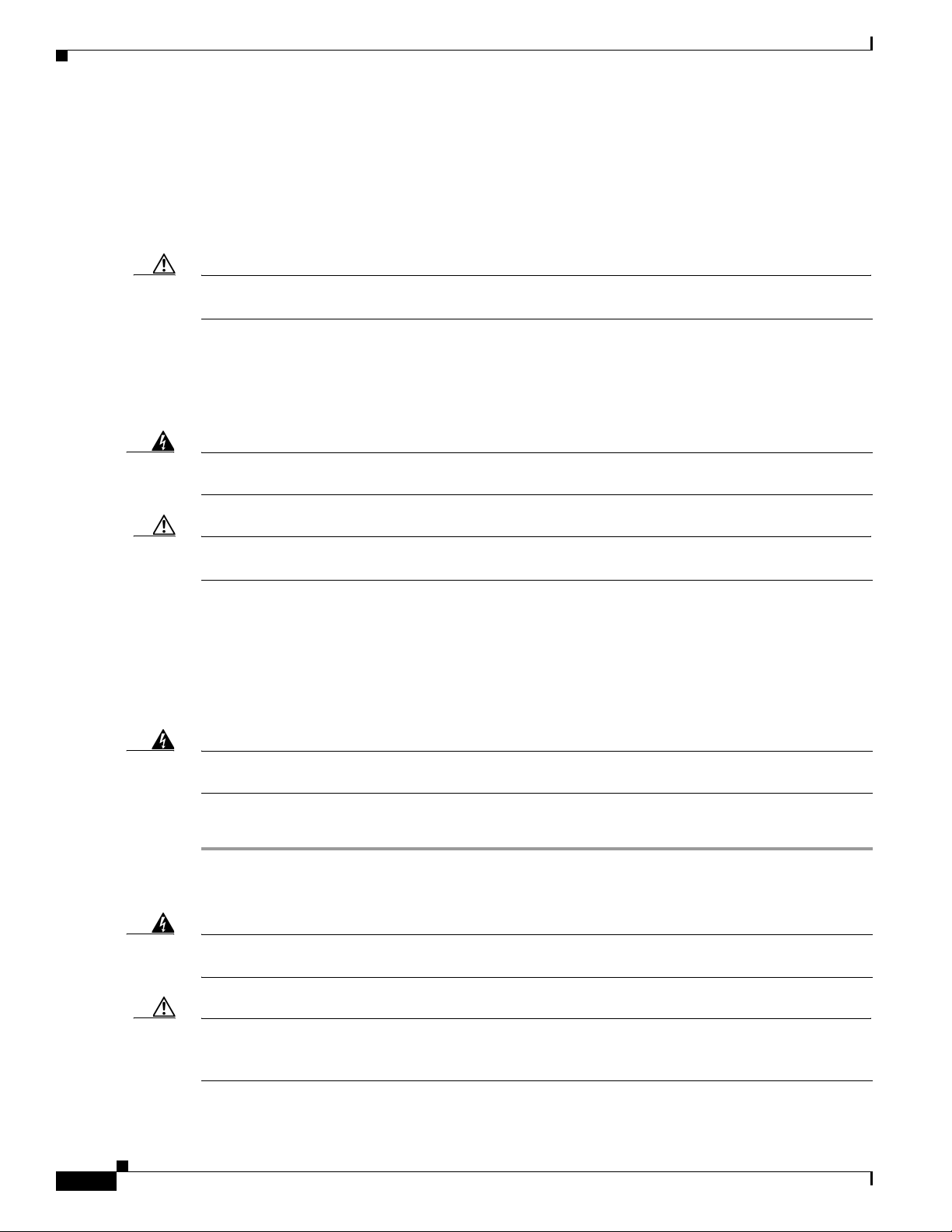
Installing the Lightning Arrestor Outdoors
If you install the lightning arrestor outdoors, use the supplied ground lug and a heavy wire (#6 solid
copper) to connect it to a good earth ground, such as a ground rod. The connection should be as short as
possible.
Figure 2-24 Lightning Arrestor Details
OL-30864-01
1 Nut 4 Unprotected side (to antenna)
2 Lockwasher 5 Protected side (to wireless device)
3 Ground lug
Cisco Aironet 1530 Series Outdoor Access Point Hardware Installation Guide
2-39
Page 3

Grounding the Access Point
Cable for the Lightning Arrestor
Coaxial cable loses efficiency as the frequency increases, resulting in signal loss. The cable should be
kept as short as possible because cable length also determines the amount of signal loss (the longer the
run, the greater the loss).
Cisco recommends a high-quality, low-loss cable for use with the lightning arrestor.
Grounding the Access Point
The access point must be grounded before connecting power.
Chapter 2 Installing the Access Point
Warning
Warning
Step 1 If using insulated 6-AWG copper ground wire, strip the insulation as required for the grounding lug.
Step 2 Use the appropriate crimping tool to crimp the bare 6-AWG copper ground wire to the supplied
Step 3 Open the anti-corrosion sealant (supplied), and apply a liberal amount over the metal surface where the
Step 4 Connect the grounding lug to the access point grounding screw holes (see Figure 1-5) using the supplied
Step 5 If necessary, strip the other end of the ground wire and connect it to a reliable earth ground, such as a
This equipment must be externally grounded using a customer-supplied ground wire before power is
applied. Contact the appropriate electrical inspection authority or an electrician if you are uncertain
that suitable grounding is available.
Installation of the equipment must comply with local and national electrical codes.
In all outdoor installations and when powering the access point with AC power, you must follow these
instructions to properly ground the case:
grounding lug.
Note The grounding lug and hardware used must comply with local and national electrical codes.
ground strap screw holes are located (see Figure 1-5).
two Phillips head screws (M4 x10 mm) with lock washers. Tighten the grounding screw to
22 to 24 lb-in (2.49 to 2.71 Nm).
grounding rod or an appropriate grounding point on a metal streetlight pole that is grounded (see
Figure 2-3).
Statement 366
Statement 1074
Powering the Access Point
Warning
Cisco Aironet 1530 Series Outdoor Access Point Hardware Installation Guide
2-40
Installation of the equipment must comply with local and national electrical codes.
Statement 1074
OL-30864-01
Page 4

Chapter 2 Installing the Access Point
Powering the Access Point
Warning
Warning
This equipment must be externally grounded using a customer-supplied ground wire before power is
applied. Contact the appropriate electrical inspection authority or an electrician if you are uncertain
that suitable grounding is available.
Do not work on the system or connect or disconnect cables during periods of lightning activity.
Statement 1001
Statement 366
The 1532 access point supports these power sources:
• DC power – 24- 57 VDC
• Power-over-Ethernet (PoE)
The 1532 access point can be powered via the PoE input from an in-line power injector or a suitably
powered switch port. Depending on the configuration and regulatory domain, the required power for full
operation is UPoE. For the 1532E, 802.3at power is sufficient for all regulatory domains and full 2x2
MIMO operation on both 2.4 and 5 GHz radios. Either the AIR-PWRINJ4= or the AIR-PWRINJ1500-2=
power injector can be used.
For the 1532I, UPoE powered switch port or the AIR-PWRINJ1500-2= power injector is required for
full operation of the 3x3 MIMO on the 2.4 GHz radio in the regulatory domains that allow for high 2.4
GHz transmit power (Regulatory domains -A, -D, -F, -K, -N, -Q, -T, -Z). If the 1532I is powered by a
PoE+ (802.3at power) switch port or the AIR-PWRINJ4= power injector, then the access point will
automatically disable one of the 2.4 GHz transmitters and the radio will operate in 2x3 MIMO mode.
Table 2-7 AP 1530 Power Matrix
Model Configuration
1532I 3x3:3 (2.4 GHz)
2x3:2 (5 GHz)
One Tx disabled
2x3:2 (2.4 GHz)
Regulatory
Domain
A, D, K, N,
Q, T, Z
1
A, D, K, N,
Q, T, Z
Switch
Power AIR-PWRINJ1500-2= AIR-PWRINJ4=
UPoE Yes Yes
802.3at
Not Applicable Yes Not Applicable
PoE+
2x3:2 (5 GHz)
3x3:3 (2.4 GHz)
2x3:2 (5 GHz)
1532E 2x2:2 (2.4 GHz)
2x2:2 (5 GHz)
1. Not user configurable. AP will automatically disable one of the 2.4 GHz Tx if it detects only 802.3at power input.
Caution Do not place the power injector in an unprotected outdoor environment because water could get into the
C, E, F, H,
M, R, S
802.3at
PoE+
All 802.3at
PoE+
Yes Yes Yes
Yes Yes Yes
power injector and cause a short circuit and possible fire.
AC/ DC Power Adapter
AIR-PWRADPT-1530=
OL-30864-01
Cisco Aironet 1530 Series Outdoor Access Point Hardware Installation Guide
2-41
Page 5

Powering the Access Point
Chapter 2 Installing the Access Point
Warning
Connect the unit only to DC power source that complies with the Safety Extra-Low Voltage (SELV)
requirements in IEC 60950 based safety standards
Connecting a 1530 Series Power Injector
The 1530 Series Access Points support the following power injectors:
• AIR-PWRINJ1500-2= — 100-240 VAC input, indoor use only
• AIR-PWRINJ4= — 100-240 VAC input, indoor use only
The power injector provides (AIR-PWRINJ1500-2=) 56 VDC to the access point over the Ethernet cable
and supports a total end-to-end Ethernet cable length of 100 m (328 ft) from the switch to the access
point.
When your access point is powered by an optional power injector, follow these steps to complete the
installation:
Step 1 Before applying PoE to the access point, ensure that the access point is grounded (see the “Grounding
the Access Point” section on page 2-40).
Step 2 Review Figure 2-2 to identify the components needed for the installation.
Note The 1500 power injector can only be used in an indoor environment, therefore, the cable from
the injector must travel from the protected location to the outside mounted access point.
Statement 1033
Step 3 Connect a CAT5e or better Ethernet cable from your wired LAN network to the power injector.
Warning
To reduce the risk of fire, use only No. 26 AWG or larger telecommunication line cord.
Note The installer is responsible for ensuring that powering the access point from this type of power
Statement 1023
injector is allowed by local and/or national safety and telecommunications equipment standards.
Tip To forward bridge traffic, add a switch between the power injector and controller. Refer to the
Cisco Wireless Mesh Access Points, Design and Deployment Guide, Release 7.0 for more
information.
Step 4 Ensure that the antennas are connected and that a ground is attached to the access point before you apply
power to the access point.
Step 5 Connect a shielded outdoor-rated Ethernet (CAT5e or better) cable between the power injector and the
PoE-in connector of the access point (see Figure 2-25).
Step 6 Connect the Ethernet cable to the access point PoE-In port (see “Connecting an Ethernet Cable to the
Access Point” section on page 2-43).
Step 7 Continue with What to Do Next, page 2-53.
2-42
Cisco Aironet 1530 Series Outdoor Access Point Hardware Installation Guide
OL-30864-01
Page 6

Chapter 2 Installing the Access Point
347850
1
2
Connecting an Ethernet Cable to the Access Point
You need to supply these tools and materials:
• Shielded outdoor-rated Ethernet (CAT5e or better) cable with 0.2 to 0.35 in. (0.51 to 0.89 cm)
diameter
• RJ-45 connector and installation tool
• Adjustable Wrench or 28 mm box wrench
• Large Phillips or Flat Blade screwdriver
To connect the shielded Ethernet cable to the access point, follow these steps:
Step 1 Disconnect power to the power injector, and ensure all power sources to the access point are turned off.
Powering the Access Point
Warning
Step 2 Ensure a 6 AWG ground wire is connected to the access point (see the “Grounding the Access Point”
This unit might have more than one power supply connection. All connections must be removed to
de-energize the unit.
Statement 1028
section on page 2-40).
Step 3 Use a large Phillips or Flat Blade screw driver to remove the Ethernet connector plug from the access
point. Do not discard plug and rubber seal unless you are certain that the port will not have to be
re-plugged (see Figure 2-25 for the location).
Figure 2-25 Access Point PoE-In Connector- AP 1532I
OL-30864-01
1 LAN port (covered) 2 PoE-in port (covered)
Note For information on data cable entry, refer to Figure 1-1
Step 4 Loosen the Thread-Lock sealing nut of the cable gland by turning it counter clockwise, but do not
remove it (see Figure 2-26).
Cisco Aironet 1530 Series Outdoor Access Point Hardware Installation Guide
2-43
Page 7
Powering the Access Point
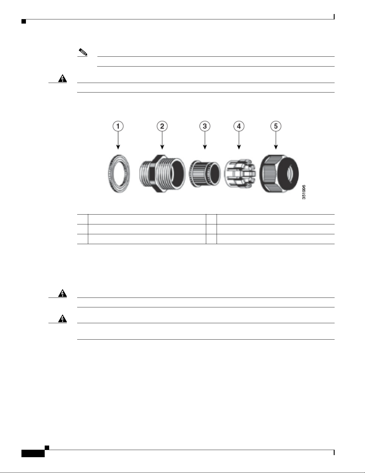
Note Verify that the cable gland has a rubber seal and ensure that it is not damaged.
Chapter 2 Installing the Access Point
Warning
Failure to install the cable gland and rubber gasket properly will cause the cable grip to leak.
Figure 2-26 Cable Gland
1 Washer (Rubber Gasket) 2 Body
3 Sealing insert 4 Clamping claw
5 Thread-lock sealing nut
Step 5
Insert the unterminated end of the Ethernet cable through the sealing nut end of the cable gland (see
Figure 2-26), and pull several inches of cable through the adapter.
Step 6 Install an RJ-45 connector on the unterminated end of the Ethernet cable using your Ethernet cable
installation tool.
2-44
Warning
Warning
To reduce the risk of fire, use only No. 26 AWG or larger telecommunication line cord.
Statement 1023
When installing the RJ-45 connector, ensure that cable gland and the rubber gasket are present and
installed properly, to avoid water leakage into the enclosure. See Figure 2-26 and Figure 2-27.
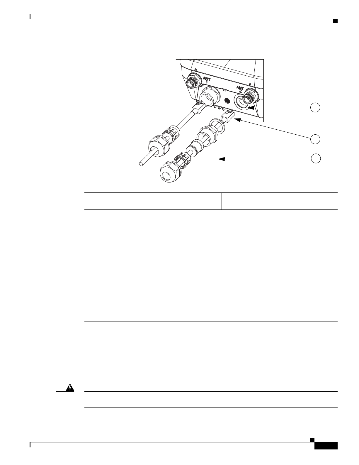
Step 7 Carefully insert the RJ-45 cable connector into the Ethernet port opening on the access point, and
connect to the internal Ethernet connector (see Figure 2-27).
Cisco Aironet 1530 Series Outdoor Access Point Hardware Installation Guide
OL-30864-01
Page 8
Chapter 2 Installing the Access Point
352056
1
2
3
Figure 2-27 Inserting RJ-45 Connector into the Ethernet Port Opening in Case
Powering the Access Point
1 Ethernet port opening in access point case. 2 RJ-45 connector, on shielded outdoor-rated
Ethernet (CAT5e or better) cable
3 Exploded view of the cable gland,on the Ethernet cable.
Step 8 Slide the cable gland with the rubber seal towards the access point, and screw the threaded end of the
body into the access point, and hand-tighten.
Step 9 Use an adjustable wrench or a 28-mm wrench to tighten the threaded end of the body into the enclosure.
Tighten to 15 lb-in.
Step 10 Use an adjustable wrench and tighten the thread-lock seal nut to 15 lb-in.
Step 11 Ensure that the antennas are connected to the access point before you apply power to the access point.
Step 12 Route your Ethernet cable, and cut off any excess cable.
Step 13 Install an RJ-45 connector on the unterminated cable end, and insert it into the power injector. For typical
installation components, see Figure 2-2.
Step 14 Turn on power to the power injector.
Connecting a DC Power Cable to the Access Point
When powering the access point with DC power, you must ensure that DC power can be conveniently
removed from the unit. The power should not be removed by disconnecting the DC power connector on
the unit.
OL-30864-01
Warning
A readily accessible two-poled disconnect device must be incorporated in the fixed wiring.
Statement 1022
Cisco Aironet 1530 Series Outdoor Access Point Hardware Installation Guide
2-45
Page 9
Powering the Access Point
1
2
Chapter 2 Installing the Access Point
Warning
Connect the unit only to DC power source that complies with the safety extra-low voltage (SELV)
requirements in IEC 60950 based safety standards.
Statement 1033
To connect a DC power cable, you need to supply these tools and material:
• Shielded outdoor-rated DC power cable (minimum 18 AWG) with outside cable diameter of 0.20 to
0.35 inch (0.51 to 0.89 cm).
• Adjustable or open-end wrench
• Small flat screw driver
• Two-pin DC power connector (Cisco supplied)
To connect the DC power cable to the access point, follow these steps:
Step 1 Before connecting DC power to the access point, ensure that the ground is connected to the access point
(see the “Grounding the Access Point” section on page 2-40).
Step 2 Turn off all power sources to the access point, including the DC power source.
Warning
Caution When installing DC power to the access point, always connect the access point end of the cable FIRST.
This unit might have more than one power supply connection. All connections must be removed to
de-energize the unit.
Statement 1028
When removing the DC power connector, always disconnect the access point end of the cable LAST.
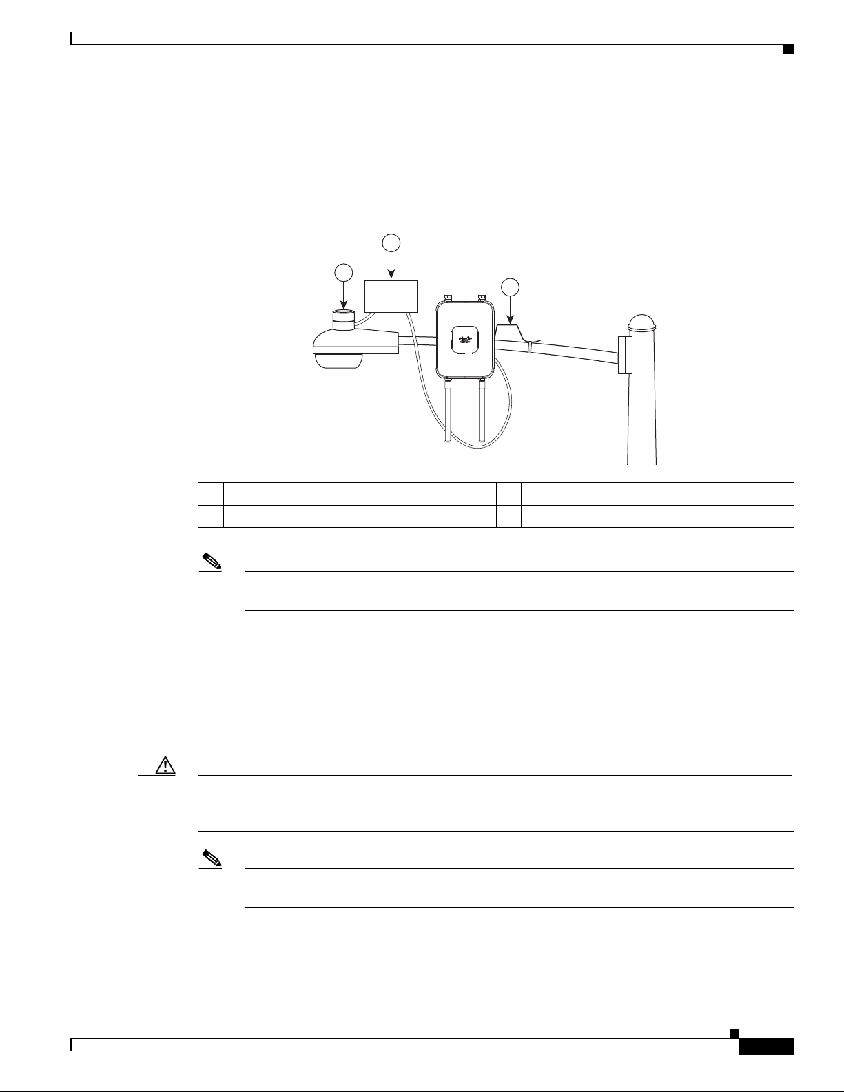
Step 3 Use a large Phillips or Flat Blade screw driver to remove the Ethernet connector plug from the access
point. Do not discard plug and rubber seal unless you are certain that the port will not have to be
re-plugged. (see Figure 2-28 for the location of the DC power connector).
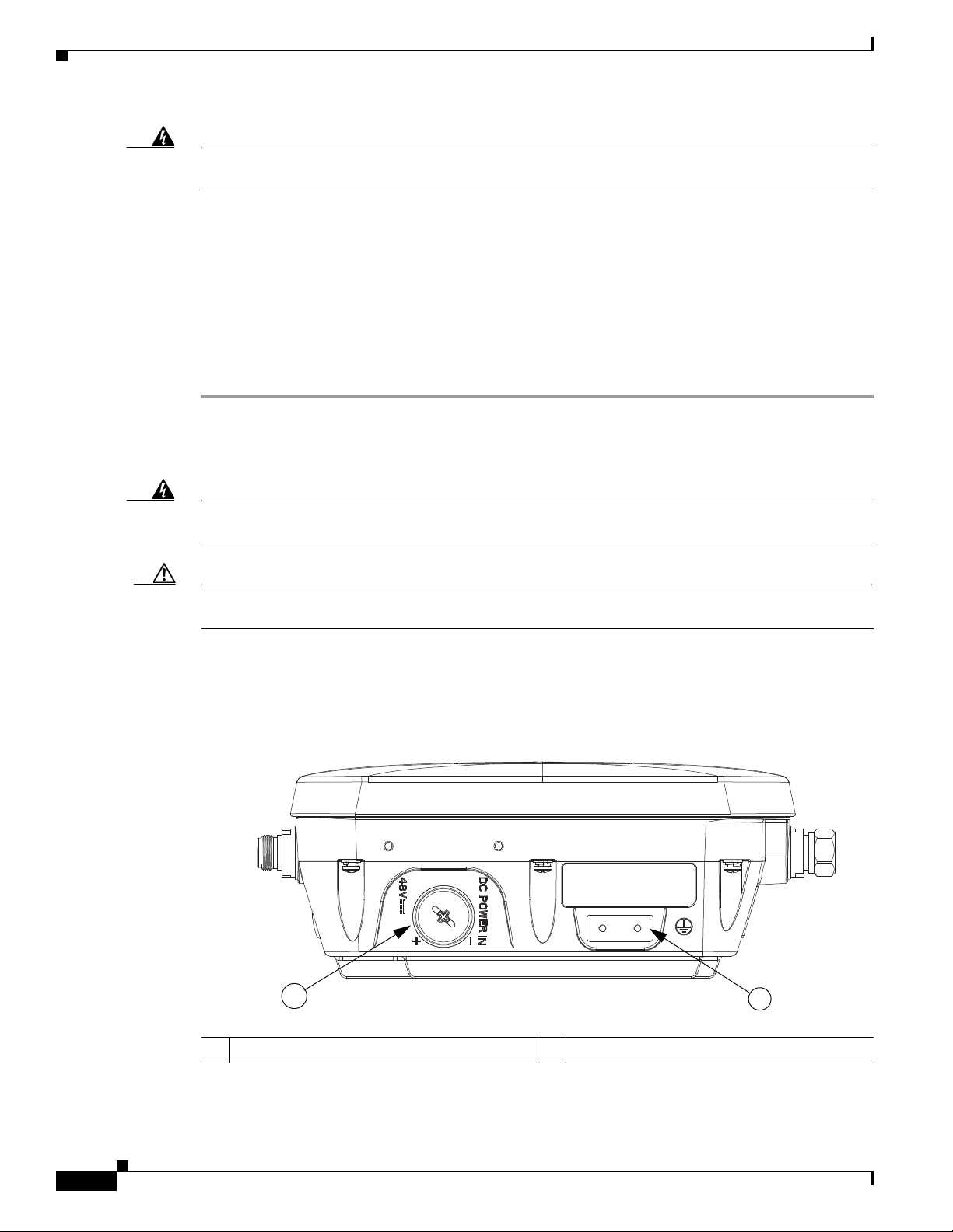
Figure 2-28 Access Point DC Power Connector and Ground Lug (Both AP 1532 Models)
347846
1 DC power port 2 Ground lug location
2-46
Cisco Aironet 1530 Series Outdoor Access Point Hardware Installation Guide
OL-30864-01
Page 10
Chapter 2 Installing the Access Point
Step 4 Loosen the thread-Lock sealing nut of the cable gland by turning it counter clockwise, but do not remove
(see Figure 2-29).
Note Verify that the cable gland has a rubber seal and ensure that it is not damaged.
Powering the Access Point
Warning
Failure to install the Cable Gland properly will cause the cable grip to leak.
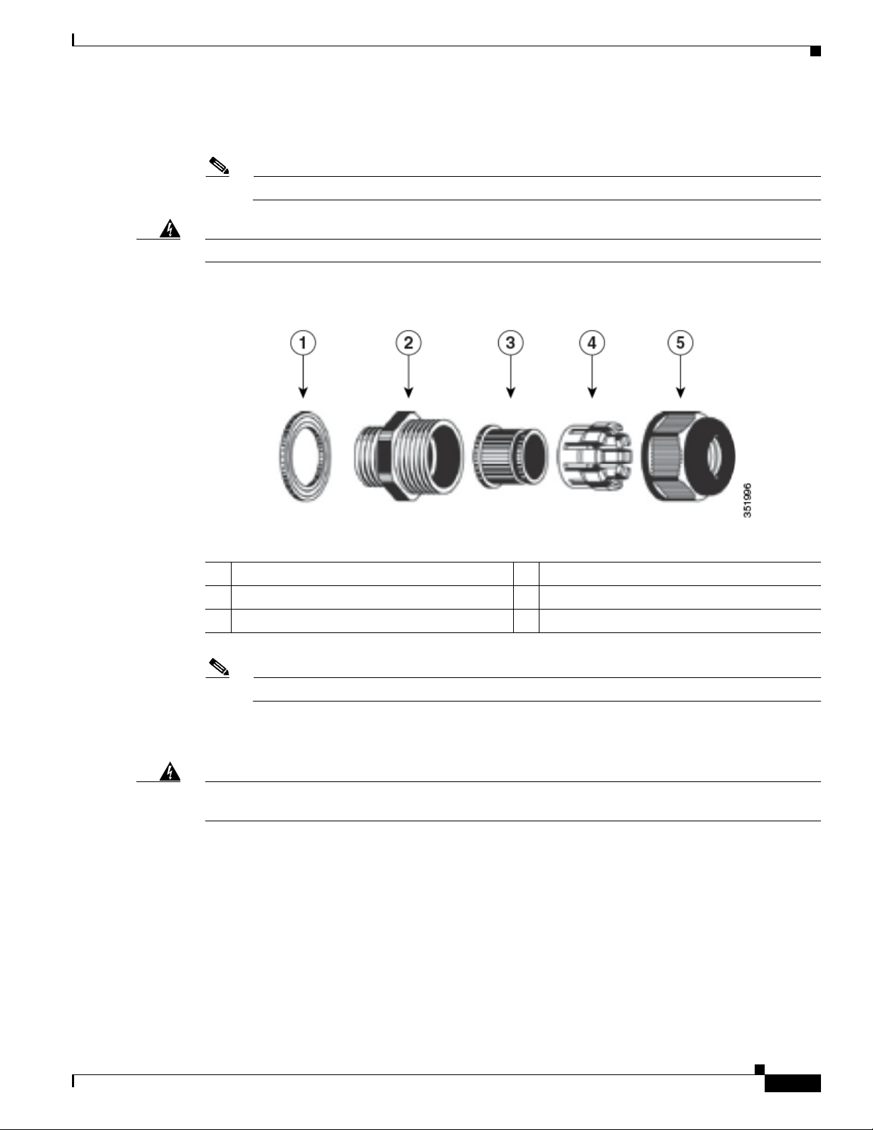
Figure 2-29 Cable Gland
1 Washer (Gasket) 2 Body
3 Sealing insert 4 Clamping claw
5 Thread-lock sealing nut
OL-30864-01
Note The cable gland accepts a cable diameter of 0.20 to 0.35 in. (0.51 to 0.89 cm).
Step 5 Insert a bare end of the DC power cable into the rounded end of the cable gland (see Figure 2-29), and
pull approximately 6 inches of cable through the adapter.
Warning
When installing the DC power cable, ensure that cable gland and the rubber gasket are present and
installed properly, to avoid water leakage into the enclosure. See Figure 2-29 and Figure 2-31.
Step 6 Strip the DC cable jacket back about 1 inch to expose the wires and strip the insulation about 3/8 inch
(9.5 mm) from each wire.
Step 7 Insert each wire into the two-position terminal strip (supplied), and tighten each wire using a 0.1 inch
(0.25 cm) flat screw driver (see Figure 2-30).
Cisco Aironet 1530 Series Outdoor Access Point Hardware Installation Guide
2-47
Page 11
Powering the Access Point
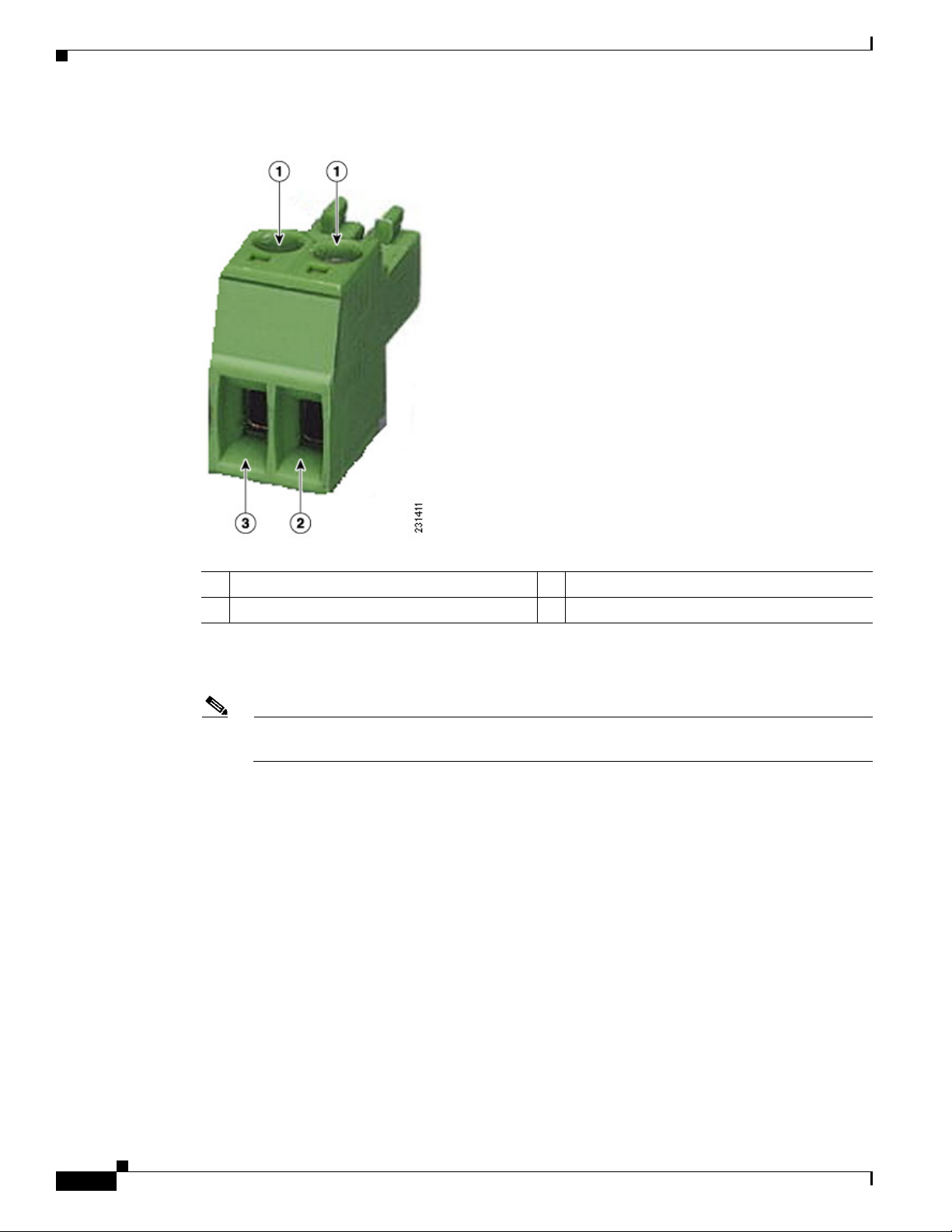
Figure 2-30 Two-Position Terminal Strip
Chapter 2 Installing the Access Point
1 Securing screws 3 Wire opening for DC +
2 Wire opening for ground (DC return)
Step 8 Insert the two-position terminal strip into the DC power opening in the access point case, and carefully
push the terminal strip into the internal connector (see Figure 2-31).
Note Ensure that the polarity of the terminal strip properly matches the polarity markings on the
enclosure (see Figure 2-32)
2-48
Cisco Aironet 1530 Series Outdoor Access Point Hardware Installation Guide
OL-30864-01
Page 12
Chapter 2 Installing the Access Point
352057
1
2
352054
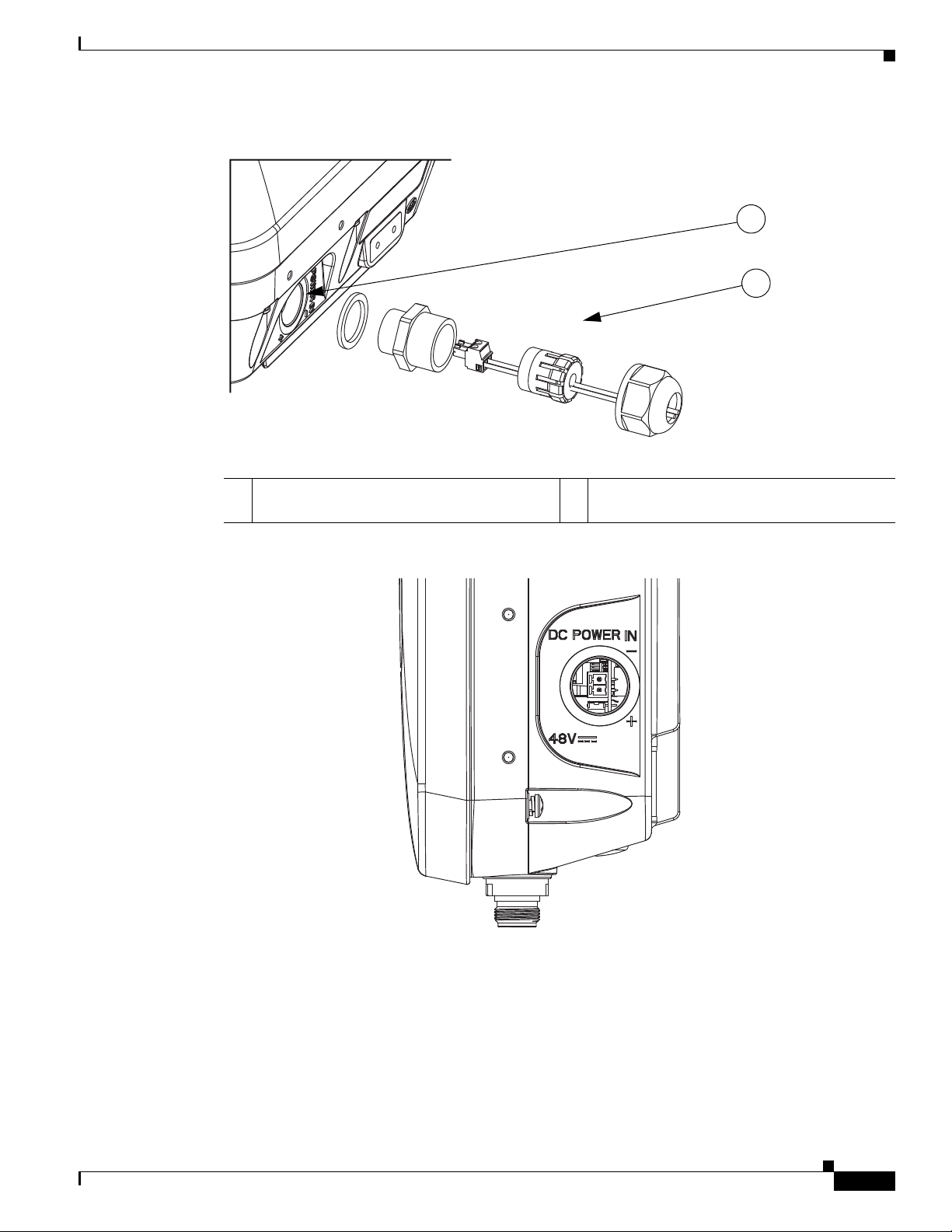
Figure 2-31 Inserting the Terminal Strip into the DC Power Opening in the Access Point Case
Powering the Access Point
1 DC power opening in access point case. Also
see Figure 2-32.
Figure 2-32 DC Power Opening in the Access Point Case
2 Exploded view of the cable gland on the DC
power cable
OL-30864-01
Step 9
Step 10 Use an adjustable wrench, a 28-mm wrench to tighten the threaded end of the body to 15 lb-in.
Step 11 Use an adjustable wrench and tighten the thread-lock seal nut to 15 lb-in.
Step 12 Ensure that the antennas are connected to the access point before you apply power to the access point.
Step 13 Turn on the DC power at the designated circuits.
Slide the cable gland with the rubber seal towards the access point, and screw the threaded end of the
body into the access point, and hand-tighten.
Cisco Aironet 1530 Series Outdoor Access Point Hardware Installation Guide
2-49
Page 13
Powering the Access Point
Connecting Streetlight AC Power
The access point can be installed on a streetlight pole and powered from a streetlight outdoor light
control using the optional streetlight power tap adapter and AC/DC power adapter,
AIR-PWRADPT-1530=. The AC/DC power adapter is used inline from the street light tap to the 1530
DC connector. The AC power tap only can be used with the AC/DC power adapter
Caution The access point can be powered by a light pole twist-lock outdoor light control that provides
100-to 277-VAC 50/60 Hz power. Do not connect to an outdoor light control powered by higher voltages.
When powering the access point with AC power other than the streetlight power tap adapter, you must
ensure that the following conditions are observed:
1. AC power can be conveniently removed from the unit. The power should not be removed by
disconnecting the AC power connector on the unit.
Chapter 2 Installing the Access Point
Warning
Caution Before connecting or disconnecting a power cord, you must remove AC power from the power cord using
A readily accessible two-poled disconnect device must be incorporated in the fixed wiring.
Statement 1022
a suitable service disconnect.
2. You must protect any AC power plugs and AC receptacles from water and other outdoor elements.
You can use a UL-listed waterproofing enclosure suitable for covering the AC receptacle and AC
power plug that supplies power to the unit as described in Article 406 of the NEC.
3. When you install the access point outdoors or in a wet or damp location, the AC branch circuit that
powers the access point should have ground fault protection (GFCI), as required by Article 210 of
the National Electrical Code (NEC).
Warning
Be very careful when connecting the streetlight adapter to Category 3 pole-top power. If you are not
careful, you may electrocute yourself or fall.
Statement 363
To install an access point on a streetlight pole, follow these steps:
Step 1 Before beginning the installation, ensure the AC power to the streetlight pole is turned off.
Step 2 Turn off power to the AC power source at the designated circuits.
2-50
Warning
Caution For your safety, when connecting the access point AC power connector, always connect the access point
This unit might have more than one power supply connection. All connections must be removed to
de-energize the unit.
Statement 1028
end of the cable FIRST. When removing the AC power connector, always disconnect the access point
end of the cable LAST.
Cisco Aironet 1530 Series Outdoor Access Point Hardware Installation Guide
OL-30864-01
Page 14
Chapter 2 Installing the Access Point
1
2
3
AC/DC
Adapter
Step 3 When using the streetlight power tap adapter (AIR-PWR-ST-LT-R3P=), ensure that the access point is
mounted within 3 feet (1 m) of the outdoor light control.
Step 4 Ensure that a 6-AWG ground wire is attached to the access point (see Figure 2-33) and connected to the
streetlight pole (for instructions see Grounding the Access Point, page 2-40).
Figure 2-33 Using the Streetlight Power Tap Adapter
Powering the Access Point
1 Outdoor light control 3 6-AWG copper grounding wire
2 AC/DC power adapter
Note Deployment of the AP as shown in the streetlight deployment in Figure 2-33 requires an
alternate AP mounting kit. See Mounting the Access Point section for more information.
Step 5 Ensure that the streetlight power tap adapter, which uses a 3-pronged LC-10 twist-lock adapter, is placed
between the outdoor light control and its fixture (refer to Figure 2-33). The LC-10 twist-lock adapter is
designed to be used with LC-10 listed outdoor light controls operating at 100 to 480 VAC, 50 to 60 Hz.
Step 6 Disconnect the outdoor light control from its fixture.
Step 7 Verify that the voltage available at the fixture is between 100 and 480 VAC, 50 to 60 Hz.
Step 8 Turn off power to the fixture at the designated circuits.
Caution When installing the streetlight power tap adapter to the access point AC power connector, always
connect the access point end of the cable FIRST. When removing the streetlight power tap adapter,
always disconnect the access point end of the cable LAST.
Step 9 Connect the streetlight power tap adapter to the access point AC/DC power adapter. Hand-tighten the
Note Ensure that your antennas are connected to the access point before you apply power to the access
point.
connector.
OL-30864-01
Cisco Aironet 1530 Series Outdoor Access Point Hardware Installation Guide
2-51
Page 15
Configuring the Access Point
1
2
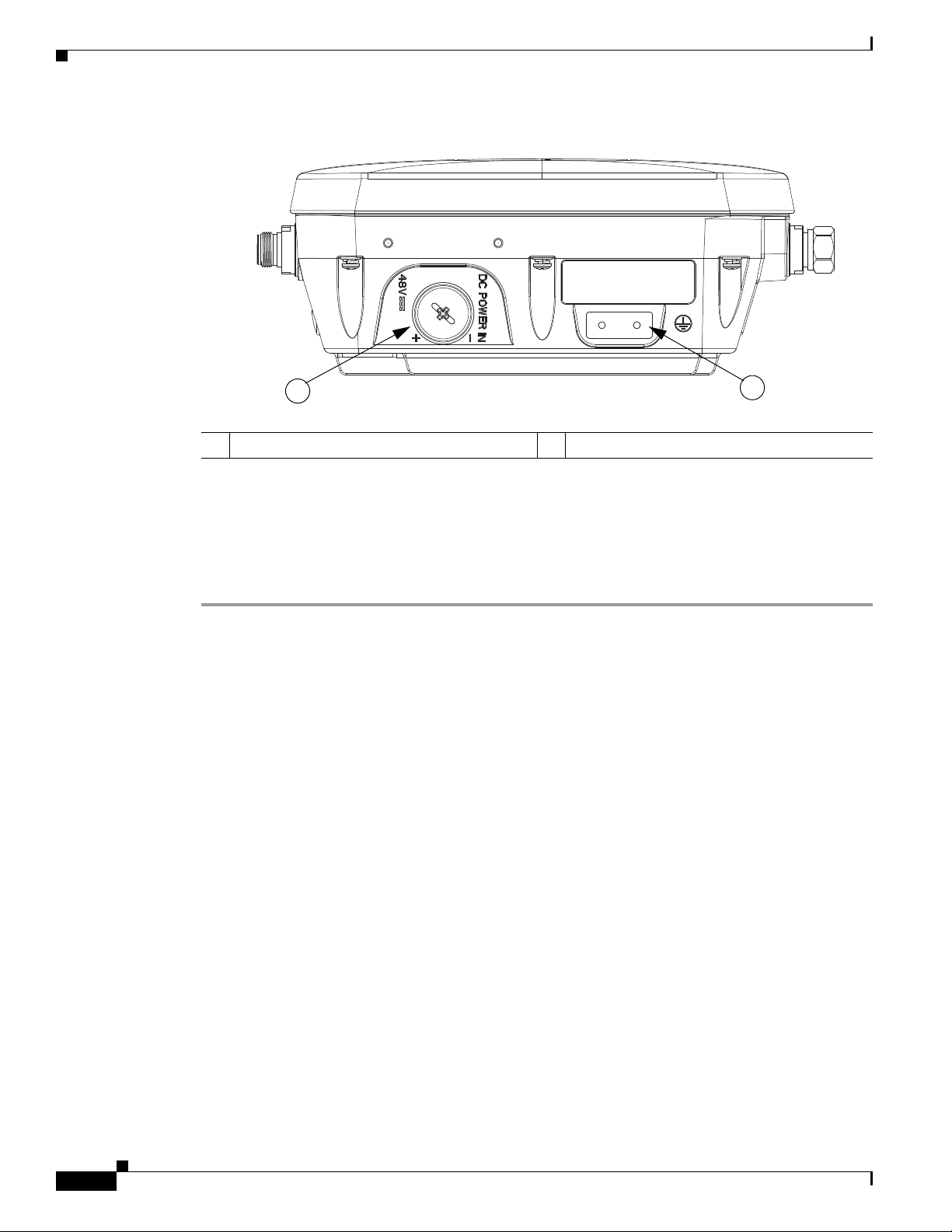
Figure 2-34 Access Point DC Power Connector and Ground Lug (Both AP 1532 Models)
1 DC power port 2 Ground lug location
Chapter 2 Installing the Access Point
347846
Step 10 Plug the streetlight power tap adapter into the outdoor light control fixture, as shown in Figure 2-33.
Step 11 Plug the outdoor light control into the streetlight power tap adapter.
Step 12 Ensure that the antennas are connected to the access point before you apply power to the access point.
Step 13 Turn on the power to the outdoor light control fixture at the designated circuits.
Configuring the Access Point
For information on configuring the access point, see the following documents:
• For Lightweight Access Points and Mesh Access Points, see the Cisco Wireless LAN Controller
Configuration Guide, which is available at:
http://www.cisco.com/en/US/docs/wireless/controller/7.6/configuration/guide/b_cg76.html
• For Mesh Access Points, see the Cisco Wireless Mesh Access Points, Design and Deployment Guide,
which is available at:
http://www.cisco.com/en/US/docs/wireless/technology/mesh/7.6/design/guide/mesh76.html
• For Access Points in autonomous mode, see the Cisco Aironet Access Points Configuration Guide
for Cisco IOS Software, which is available at:
http://www.cisco.com/en/US/docs/wireless/access_point/15_2_4_JB/configuration/guide/scg15.2.4
_JB3a_Book.html
2-52
Cisco Aironet 1530 Series Outdoor Access Point Hardware Installation Guide
OL-30864-01
Page 16

Chapter 2 Installing the Access Point
What to Do Next
When you power up a MAP that is not connected to a wired Ethernet, fiber-optic, or cable network to
the controller, the access point uses the Cisco Adaptive Wireless Path Protocol (AWPP) to bind to
another mesh access point (MAP) with the best path to a root access point (RAP) connected to the wired
network to a controller. The access point sends a discovery request when powered up. If you have
configured the access point in the controller correctly, the controller sends back a discovery response to
the access point. When that happens, the access point sends out a join request to the controller, and the
controller responds with a join confirmation response. Then the access point establishes a Control And
Provisioning of Wireless Access Points (CAPWAP) connection to the controller and gets the shared
secret configured on the controller.
Refer to the Cisco Wireless LAN Controller Configuration Guide for more information on configuring,
monitoring, and operating your access points.
What to Do Next
OL-30864-01
Cisco Aironet 1530 Series Outdoor Access Point Hardware Installation Guide
2-53
Page 17

What to Do Next
Chapter 2 Installing the Access Point
2-54
Cisco Aironet 1530 Series Outdoor Access Point Hardware Installation Guide
OL-30864-01
Page 18

CHA P TER
3
Troubleshooting
This chapter provides troubleshooting procedures for basic problems with the access point. For the most
up-to-date, detailed troubleshooting information, refer to the Cisco Technical Support and
Documentation website at the following URL:
http://www.cisco.com/cisco/web/support/index.html
Sections in this chapter include:
• Guidelines for Using the Access Points, page 3-2
• Controller MAC Filter List, page 3-3
• Using DHCP Option 43, page 3-3
• Monitoring the Access Point LEDs, page 3-4
• Verifying Controller Association, page 3-6
• Changing the Bridge Group Name, page 3-7
• Access Point Power Injector, page 3-7
• Access Point Power Injector, page 3-7
• Using the Reset Button, page 3-9
OL-30864-01
Cisco Aironet 1530 Series Outdoor Access Point Hardware Installation Guide
3-1
Page 19

Guidelines for Using the Access Points
Guidelines for Using the Access Points
You should keep these guidelines in mind when you use the access points:
• The access point only supports Layer 3 CAPWAP communications with the controllers.
In Layer 3 operation, the access point and the controller can be on the same or different subnets. The
access point communicates with the controller using standard IP packets. A Layer 3 access point on
a different subnet than the controller requires a DHCP server on the access point subnet and a route
to the controller. The route to the controller must have destination UDP ports 12222 and 12223 open
for CAPWAP communications. The route to the primary, secondary, and tertiary controllers must
allow IP packet fragments.
• Before deploying your access points, ensure that the following has been done:
–
Your controllers are connected to switch ports that are configured as trunk ports.
–
Your access points are connected to switch ports that are configured as untagged access ports.
–
A DHCP server is reachable by your access points and has been configured with Option 43.
Option 43 provides the IP addresses of the management interfaces of your controllers. Typically,
a DHCP server can be configured on a Cisco switch.
–
Optionally, a DNS server can be configured to enable CISCO-CAPWAP-CONTROLLER. Use
local domain to resolve to the IP address of the management interface of your controller.
Chapter 3 Troubleshooting
–
Your controllers are configured and reachable by the access points.
–
Your controllers are configured with the access point MAC addresses and the MAC filter list is
enabled.
–
Your switch must forward DHCP requests.
• After the access points are associated to the controller, you should change the bridge group name
(BGN) from the default value. With the default BGN, the mesh access points (MAPs) can potentially
try to connect with other mesh networks and slow down the convergence of the network.
Important Notes
Convergence Delays
During deployment, the access points can experience convergence delays due to various causes. The
following list identifies some operating conditions that can cause convergence delays:
• A root access point (RAP) attempts to connect to a controller using any of the wired ports (cable,
fiber-optic, PoE-in). If the wired ports are operational, the RAP can potentially spend several
minutes on each port prior to connecting to a controller.
• If a RAP is unable to connect to a controller over the wired ports, it attempts to connect using the
wireless network. This results in additional delays when multiple potential wireless paths are
available.
• If a MAP is unable to connect to a RAP using a wireless connection, it then attempts to connect using
any available wired port. The access point can potentially spend several minutes for each connection
method, before attempting the wireless network again.
3-2
Cisco Aironet 1530 Series Outdoor Access Point Hardware Installation Guide
OL-30864-01
Page 20

Chapter 3 Troubleshooting
Bridge Loop
The access point supports packet bridging between wired and wireless network connections. The same
network must never be connected to multiple wired ports on an access point or on two bridged access
points. A bridge loop causes network routing problems.
Controller DHCP Server
The controller DHCP server only assigns IP addresses to lightweight access points and wireless clients
associated to an access point. It does not assign an IP address to other devices, including Ethernet
bridging clients on the mesh access points.
MAP Data Traffic
If the signal on the access point backhaul channel has a high signal-to-noise ratio, it is possible for a
MAP to connect to the controller, via parent node, but not be able to pass data traffic, such as pinging
the access point. This can occur because the default data rate for backhaul control packets is set to 6
Mb/s, and the backhaul data rate set to auto by the user.
Controller MAC Filter List
Controller MAC Filter List
Before activating your access point, you must ensure that the access point MAC address has been added
to the controller MAC filter list and that Mac Filter List is enabled.
Note The access point MAC address and barcode is located on the bottom of the unit. When two MAC
addresses are shown, use the top MAC address.
To view the MAC addresses added to the controller MAC filter list, you can use the controller CLI or the
controller GUI:
• Controller CLI—Use the show macfilter summary controller CLI command to view the MAC
addresses added to the controller filter list.
• Controller GUI—Log into your controller web interface using a web browser, and choose
SECURITY > AAA > MAC Filtering to view the MAC addresses added to the controller filter list.
Using DHCP Option 43
You can use DHCP Option 43 to provide a list of controller IP addresses to the access points, enabling
the access point to find and join a controller. Refer to the product documentation for your DHCP server
for instructions on configuring DHCP Option 43. For additional information, refer to the “Configuring
DHCP Option 43” section on page F-1.
OL-30864-01
Cisco Aironet 1530 Series Outdoor Access Point Hardware Installation Guide
3-3
Page 21

Monitoring the Access Point LEDs
347848
LED
Indicator
Monitoring the Access Point LEDs
If your access point is not working properly, look at the LEDs on the bottom of the unit. You can use
them to quickly assess the status of the unit. Figure 3-1 shows the location of the access point LEDs.
Figure 3-1 Access Point LEDs –Shown on the Bottom of AP 1532E
Chapter 3 Troubleshooting
Note It is expected that there will be small variations in LED color intensity and hue from unit to unit. This is
within the normal range of the LED manufacturer specifications and is not a defect.
The access point LED signals are listed in Table 3-1.
Table 3-1 Access Point LED Signals
LED Message
Color Meaning
Type
Boot loader
status sequence
Boot loader
warnings
Blinking Green Boot loader status sequence:
• DRAM memory test in progress
• DRAM memory test OK
• Board initialization in progress
• Initializing FLASH file system
• FLASH memory test OK
• Initializing Ethernet
• Ethernet OK
• Starting Cisco IOS
• Initialization successful
Blinking Amber Configuration recovery is in progress (the MODE button
has been pushed for 2-3 seconds)
Solid Red There is an Ethernet failure or an image recovery (the
MODE button has been pushed for 20-30 seconds)
Blinking Green An image recovery is in progress (the MODE button has
been released)
3-4
Cisco Aironet 1530 Series Outdoor Access Point Hardware Installation Guide
OL-30864-01
Page 22

Chapter 3 Troubleshooting
Monitoring the Access Point LEDs
LED Message
Type
Boot loader
errors
Cisco IOS
errors
Association
status
Operating
Status
Alignment
Mode
Color Meaning
Solid Red There has been a DRAM memory test failure
Blinking Red and Amber There has been a FLASH file system failure
Blinking Red and Off This sequence may indicate any of the following:
• Environment variable failure
• Bad MAC address
• Ethernet failure during image recovery
• Boot environment failure
• No Cisco image file
• Boot failure
Solid Red There has been a software failure; a disconnect then
reconnect of the unit power may resolve the issue
Cycling through Red,
This is a general warning of insufficient inline power.
Green, Amber and Off
Chirping (short blips)
Green
This status indicates a normal operating condition. The
unit is joined to a controller, but no wireless client is
associated with it.
Solid Green Normal operating condition with at least one wireless
client associated with the unit
Blinking Amber A software upgrade is in progress
Cycling through Green,
Discovery/join process is in progress
Red and Amber
Rapidly cycling through
Red, Green, Amber and
This status indicates that the Access Point location
command has been invoked.
Off
Blinking Red This status indicates that an Ethernet link is not
operational
Color Signal Level (dBm)
Solid Green > –44
Fast blinking Green –47 to –44
Medium blinking Green –50 to –47
Solid Amber –53 to –50
Fast blinking Amber –57 to –53
Medium blinking Amber –60 to –57
Slow blinking Amber –63 to –60
Slow blinking Red –66 to –63
Medium blinking Red –69 to –66
Fast blinking Red –72 to –69
Solid Red –75 to –72
Off < –75
OL-30864-01
Cisco Aironet 1530 Series Outdoor Access Point Hardware Installation Guide
3-5
Page 23

Verifying Controller Association
Verifying Controller Association
To verify that your access point is associated to the controller, follow these steps:
Step 1 Log into your controller web interface using a web browser.
You can also use the controller CLI show ap summary command from the controller console port.
Step 2 Click Wireless, and verify that your access point MAC address is listed under Ethernet MAC.
Step 3 Log out of the controller, and close your web browser.
Chapter 3 Troubleshooting
3-6
Cisco Aironet 1530 Series Outdoor Access Point Hardware Installation Guide
OL-30864-01
Page 24

Chapter 3 Troubleshooting
Changing the Bridge Group Name
The bridge group name (BGN) controls the association of the access points to a RAP. BGNs can be used
to logically group the radios to avoid different networks on the same channel from communicating with
each other. This setting is also useful if you have more than one RAP in your network in the same area.
If you have two RAPs in your network in the same area (for more capacity), we recommend that you
configure the two RAPs with different BGNs and on different channels.
The BGN is a string of ten characters maximum. A factory-set bridge group name (NULL VALUE) is
assigned during manufacturing. It is not visible to you, but allows new access point radios to join a
network of new access points. The BGN can be reconfigured from the Controller CLI and GUI. After
configuring the BGN, the access point reboots.
After the access points are deployed and associated to the controller, the BGN should be changed from
the default value to prevent the MAPs from attempting to associate to other mesh networks.
The BGN should be configured very carefully on a live network. You should always start with the most
distant access point (last node) from the RAP and move towards the RAP. If you start configuring the
BGN in a different location, then the access points beyond this point (farther away) are dropped, as they
have a different BGN.
To configure the BGN for the access points using the controller GUI, follow these steps:
Changing the Bridge Group Name
Step 1 Log into your controller using a web browser.
Step 2 Click Wireless. When access points associates to the controller, the access point name appears in the AP
Name list.
Step 3 Click on an access point name.
Step 4 Find the Mesh Information section, and enter the new BGN in the Bridge Group Name field.
Step 5 Click Apply.
Step 6 Repeat Steps 2 through 5 for each access point.
Step 7 Log out from your controller, and close your web browser.
Access Point Power Injector
The power injector (AIR-PWRINJ1500-2=) has three LEDs on the front end of the case (see Figure 3-2).
For detailed information on the power injector, see the Cisco Aironet 1550 Series Outdoor Access Point
Power Injector Installation Instructions.
OL-30864-01
Cisco Aironet 1530 Series Outdoor Access Point Hardware Installation Guide
3-7
Page 25

Access Point Power Injector
Figure 3-2 Power Injector Connectors and LEDs
Chapter 3 Troubleshooting
1
1 Mounting tabs 4 AC POWER LED
2 AP POWER LED 5 TO AP—Ethernet connector (RJ-45) to access point
(10/100/1000BASE-T)
3 FAULT LED 6 TO SWITCH—Ethernet connector (RJ-45) to switch
(10/100/1000BASE-T)
211485
231484
12 3 4 5 6
3-8
Cisco Aironet 1530 Series Outdoor Access Point Hardware Installation Guide
OL-30864-01
Page 26

Chapter 3 Troubleshooting
352055
1
2
Monitoring the Power Injector LEDs
You can use the power injector LEDs to check the power injector status. The LEDs provide the following
status information:
• AP POWER—Turns solid green after successful discovery; indicates that power injector is
supplying power to the access point.
• FAULT—Turns solid red when a fault occurs during discovery mode or power-up. Check Ethernet
cables and connections before contacting your support organization for assistance.
• AC POWER—Turns solid green when power injector is receiving AC power and is ready to provide
power to the access point.
Using the Reset Button
The access point has a reset button located on the left side of the enclosure, inside the Console-Reset
port, under the hex-shaped sealed plug.
Using the Reset Button
Caution Inspect the seal of the plug and properly tighten it every time the plug is removed and replaced. Tighten
the plug to 15 lbf-in.
Figure 3-3 Reset Button Location - Models AIR-CAP1552E-x-K9 and AIR-CAP1552EU-x-K9
OL-30864-01
1 Console Port 2 Reset Button
Cisco Aironet 1530 Series Outdoor Access Point Hardware Installation Guide
3-9
Page 27

Using the Reset Button
Resetting the Access Point
Using the Reset button you can either return the AP back to its default factory-shipped configuration or
download the latest software image from the default TFTP servers.
To use the Reset button:
Step 1 Using a wrench, remove the hex-shaped plug from the Console-Reset port. Do not loose the seal around
the plug.
Step 2 To press and hold the Reset button, use a straightened paperclip or a small screwdriver or a pen.
• To reset the AP back to its default factory-shipped configuration, during power cycle, press and hold
the Reset button (for about 2 to 3 seconds) until the LED blinks amber.
• To download the software image (ap1g3-k9w7-tar.default) from the default TFTP servers (servers
with IP address in the range of 10.0.0.2 to 10.0.0.30), during power cycle, press and hold the Reset
button (for about 20 to 30 seconds) until the LED turns red.
Step 3 Inspect the hex-shaped plug attached to the lanyard for any damage to the sealing face and the gasket. If
the gasket has any signs of damage, it should be replaced to avoid water leakage into the unit.
Step 4 Replace the hex-shaped plug back and tighten it to 15 lbf-in.
Chapter 3 Troubleshooting
3-10
Cisco Aironet 1530 Series Outdoor Access Point Hardware Installation Guide
OL-30864-01
Page 28

APPENDIX
A
Translated Safety Warnings
For translated safety warnings, refer to the safety warning document that shipped with your access point or
that is available on Cisco.com.
To browse to the document on Cisco.com, follow these steps:
Step 1 Click this link and go to the Cisco Wireless documentation home page:
http://www.cisco.com/en/US/products/hw/wireless/index.html
Step 2 Click Support and the Support and Documentation page displays.
Step 3 Click Wireless in the Find Product Support column.
Step 4 Click 1530.
Step 5 Click Install and Upgrade.
Step 6 Click Install and Upgrade Guides.
Step 7 Click Translated Safety Warnings for Cisco Aironet 1530 Series Outdoor Mesh Access Points.
OL-30864-01
Cisco Aironet 1530 Series Outdoor Access Point Hardware Installation Guide
A-1
Page 29

Appendix A Translated Safety Warnings
A-2
Cisco Aironet 1530 Series Outdoor Access Point Hardware Installation Guide
OL-30864-01
Page 30

APPENDIX
B
Declarations of Conformity and Regulatory Information
This appendix provides declarations of conformity and regulatory information for the Cisco Aironet
1532 Outdoor Access Point.
This appendix contains the following sections:
• Manufacturers Federal Communication Commission Declaration of Conformity Statement,
page B-2
• Industry Canada, page B-3
• European Community, Switzerland, Norway, Iceland, and Liechtenstein, page B-4
• Declaration of Conformity for RF Exposure, page B-7
• Guidelines for Operating Cisco Aironet Access Points in Japan, page B-8
• VCCI Statement for Japan, page B-9
• Administrative Rules for Cisco Aironet Access Points in Taiwan, page B-9
• EU Declaration of Conformity, page B-12
OL-30864-01
Cisco Aironet 1530 Series Outdoor Access Point Hardware Installation Guide
B-1
Page 31

Appendix B Declarations of Conformity and Regulatory Information
Tested To Comply
With FCC Standards
FOR HOME OR OFFICE USE
Manufacturers Federal Communication Commission Declaration of Conformity Statement
Manufacturers Federal Communication Commission
Declaration of Conformity Statement
Models: FCC Certification number:
AIR-CAP1532I-A-K9 LDK102090P
AIR-CAP1532E-A-K9 LDK102089P
AIR-AP1532I-UXK9
AIR-AP1532E-UXK9
Manufacturer:
Cisco Systems, Inc.
170 West Tasman Drive
San Jose, CA 95134-1706
USA
This device complies with Part 15 rules. Operation is subject to the following two conditions:
1. This device may not cause harmful interference, and
2. This device must accept any interference received, including interference that may cause undesired
operation.
This equipment has been tested and found to comply with the limits of a Class A digital device, pursuant
to Part 15 of the FCC Rules. These limits are designed to provide reasonable protection against harmful
interference when the equipment is operated in a residential environment. This equipment generates,
uses, and radiates radio frequency energy, and if not installed and used in accordance with the
instructions, may cause harmful interference. However, there is no guarantee that interference will not
occur. If this equipment does cause interference to radio or television reception, which can be determined
by turning the equipment off and on, the user is encouraged to correct the interference by one of the
following measures:
• Reorient or relocate the receiving antenna.
• Increase separation between the equipment and receiver.
• Connect the equipment to an outlet on a circuit different from which the receiver is connected.
• Consult the dealer or an experienced radio/TV technician.
Caution The Part 15 radio device operates on a non-interference basis with other devices operating at this
frequency when using Cisco-supplied antennas. Any changes or modification to the product not
expressly approved by Cisco could void the user’s authority to operate this device.
B-2
Cisco Aironet 1530 Series Outdoor Access Point Hardware Installation Guide
OL-30864-01
Page 32

Appendix B Declarations of Conformity and Regulatory Information
Caution To meet regulatory restrictions, the access point must be professionally installed.
Industry Canada
Models: IC Certification Number:
AIR-CAP1532I-A-K9 2461B-LDK102090P
AIR-CAP1532E-A-K9 2461B-LDK102089P
AIR-AP1532I-UXK9
AIR-AP1532E-UXK9
Canadian Compliance Statement
This Class A Digital apparatus meets all the requirements of the Canadian Interference-Causing
Equipment Regulations.
Cet appareil numerique de la classe A respecte les exigences du Reglement sur le material broilleur du
Canada.
This device complies with Class A Limits of Industry Canada. Operation is subject to the following two
conditions:
Industry Canada
1. This device may not cause harmful interference, and
2. This device must accept any interference received, including interference that may cause undesired
operation.
Cisco Aironet Access Points are certified to the requirements of RSS-210. The use of this device in a
system operating either partially or completely outdoors may require the user to obtain a license for the
system according to the Canadian regulations. For further information, contact your local Industry
Canada office.
This device has been designed to operate with antennas having a maximum gain of 13 dBi for 2.4 GHz
and 14 dBi for 5 GHz. Antennas having a gain greater are strictly prohibited for use with this device.
The required antenna impedance is 50 ohms.
To reduce potential radio interference to other users, the antenna type and its gain should be so chosen
that the equivalent isotropically radiated power (EIRP) is not more than that permitted for successful
communication.
Declaration of Conformity for RF Exposure
This access point product has been found to be compliant to the requirements set forth in CFR 47
Section 1.1307 addressing RF Exposure from radio frequency devices as defined in Evaluating
Compliance with FCC Guidelines for Human Exposure to Radio Frequency Electromagnetic Fields.
Antennas that have 8 dBi to 14 dBi gain should be located at a minimum of 19.7 inches (50 cm) or more
from the body of all persons. Antennas that have less than 8 dBi gain should be located at a minimum of
7.9 inches (20 cm) or more from the body of all persons.
This access point is also compliant to EN 50835 for RF exposure.
OL-30864-01
Cisco Aironet 1530 Series Outdoor Access Point Hardware Installation Guide
B-3
Page 33

Appendix B Declarations of Conformity and Regulatory Information
European Community, Switzerland, Norway, Iceland, and Liechtenstein
European Community, Switzerland, Norway, Iceland, and
Liechtenstein
Access Point Models:
AIR-CAP1532I-E-K9
AIR-CAP1532E-E-K9
AIR-AP1532I-UXK9
AIR-AP1532E-UXK9
Declaration of Conformity with regard to the R&TTE Directive 1999/5/EC & Medical Directive 93/42/EEC
This declaration is only valid for configurations (combinations of software, firmware, and hardware)
provided and supported by Cisco Systems. The use of software or firmware not provided and supported
by Cisco Systems may result in the equipment no longer being compliant with the regulatory
requirements.
B-4
Cisco Aironet 1530 Series Outdoor Access Point Hardware Installation Guide
OL-30864-01
Page 34

Appendix B Declarations of Conformity and Regulatory Information
Declaration of Conformity with regard to the R&TTE Directive 1999/5/EC & Medical Directive 93/42/EEC
OL-30864-01
Cisco Aironet 1530 Series Outdoor Access Point Hardware Installation Guide
B-5
Page 35

Appendix B Declarations of Conformity and Regulatory Information
Declaration of Conformity with regard to the R&TTE Directive 1999/5/EC & Medical Directive 93/42/EEC
B-6
The following standards were applied:
EMC—EN 301.489-1 v1.8.1; EN 301.489-17 v2.1.1
Health & Safety—EN60950-1: 2005; EN 50385: 2002
Radio—EN 300 328 v 1.7.1; EN 301.893 v 1.5.1
The conformity assessment procedure referred to in Article 10.4 and Annex III of Directive 1999/5/EC
has been followed.
This device also conforms to the EMC requirements of the Medical Devices Directive 93/42/EEC.
Note This equipment is intended to be used in all EU and EFTA countries. Outdoor use may be restricted to
certain frequencies and/or may require a license for operation. For more details, contact Cisco Corporate
Compliance.
The product carries the CE Mark:
Cisco Aironet 1530 Series Outdoor Access Point Hardware Installation Guide
OL-30864-01
Page 36

Appendix B Declarations of Conformity and Regulatory Information
Declaration of Conformity for RF Exposure
The following is the declaration of conformity for RF exposure for the United States, Canada, European
Union and Australia.
United States
This system has been evaluated for RF exposure for Humans in reference to ANSI C 95.1 (American
National Standards Institute) limits. The evaluation was based on ANSI C 95.1 and FCC OET Bulletin
65C rev 01.01. To maintain compliance, the minimum separation distance for antennas that have 8 dBi
to 14 dBi gain, is 19.7 inches (50 cm) from general bystanders. The minimum separation distance from
antennas that have less than 8 dBi gain to general bystanders is 7.9 inches (20 cm).
Canada
This system has been evaluated for RF exposure for Humans in reference to ANSI C 95.1 (American
Declaration of Conformity for RF Exposure
National Standards Institute) limits. The evaluation was based on RSS-102 Rev 2. To maintain
compliance, the minimum separation distance for antennas that have 8 dBi to 14 dBi gain, is 19.7 inches
(50 cm) from general bystanders. The minimum separation distance from antennas that have less than
8 dBi gain to general bystanders is 7.9 inches (20 cm).
European Union
This system has been evaluated for RF exposure for Humans in reference to the ICNIRP (International
Commission on Non-Ionizing Radiation Protection) limits. The evaluation was based on the EN 50385
Product Standard to Demonstrate Compliance of Radio Base stations and Fixed Terminals for Wireless
Telecommunications Systems with basic restrictions or reference levels related to Human Exposure to
Radio Frequency Electromagnetic Fields from 300 MHz to 40 GHz. To maintain compliance, the
minimum separation distance for antennas that have 8 dBi to 14 dBi gain, is 19.7 inches (50 cm) from
general bystanders. The minimum separation distance from antennas that have less than 8 dBi gain to
general bystanders is 7.9 inches (20 cm).
Australia
This system has been evaluated for RF exposure for Humans as referenced in the Australian Radiation
Protection standard and has been evaluated to the ICNIRP (International Commission on Non-Ionizing
Radiation Protection) limits. To maintain compliance, the minimum separation distance for antennas that
have 8 dBi to 14 dBi gain, is 19.7 inches (50 cm) from general bystanders. The minimum separation
distance from antennas that have less than 8 dBi gain to general bystanders is 7.9 inches (20 cm).
OL-30864-01
Cisco Aironet 1530 Series Outdoor Access Point Hardware Installation Guide
B-7
Page 37

Appendix B Declarations of Conformity and Regulatory Information
03-6434-6500
43768
Guidelines for Operating Cisco Aironet Access Points in Japan
Guidelines for Operating Cisco Aironet Access Points in Japan
This section provides guidelines for avoiding interference when operating Cisco Aironet access points
in Japan. These guidelines are provided in both Japanese and English.
Lightweight Access Point Model:
AIR-CAP1532E-Q-K9
AIR-CAP1532I-Q-K9
AIR-AP1532I-UXK9
AIR-AP1532E-UXK9
Japanese Translation
English Translation
This equipment operates in the same frequency bandwidth as industrial, scientific, and medical devices
such as microwave ovens and mobile object identification (RF-ID) systems (licensed premises radio
stations and unlicensed specified low-power radio stations) used in factory production lines.
1. Before using this equipment, make sure that no premises radio stations or specified low-power radio
stations of RF-ID are used in the vicinity.
2. If this equipment causes RF interference to a premises radio station of RF-ID, promptly change the
frequency or stop using the device; contact the number below and ask for recommendations on
avoiding radio interference, such as setting partitions.
3. If this equipment causes RF interference to a specified low-power radio station of RF-ID, contact
the number below.
Cisco Aironet 1530 Series Outdoor Access Point Hardware Installation Guide
B-8
OL-30864-01
Page 38

Appendix B Declarations of Conformity and Regulatory Information
Contact Number: 03-6434-6500
VCCI Statement for Japan
Administrative Rules for Cisco Aironet Access Points in Taiwan
Warning
This is a Class A product based on the standard of the Voluntary Control Council for Interference by
Information Technology Equipment (VCCI). If this equipment is used in a domestic environment, radio
disturbance may arise. When such trouble occurs, the user may be required to take corrective
actions.
Administrative Rules for Cisco Aironet Access Points in Taiwan
This section provides administrative rules for operating Cisco Aironet Access Points in Taiwan. The
rules are provided in both Chinese and English.
OL-30864-01
Cisco Aironet 1530 Series Outdoor Access Point Hardware Installation Guide
B-9
Page 39

Administrative Rules for Cisco Aironet Access Points in Taiwan
Chinese Translation
Appendix B Declarations of Conformity and Regulatory Information
B-10
Cisco Aironet 1530 Series Outdoor Access Point Hardware Installation Guide
OL-30864-01
Page 40

Appendix B Declarations of Conformity and Regulatory Information
English Translation
Administrative Rules for Low-power Radio-Frequency Devices
Article 12
For those low-power radio-frequency devices that have already received a type-approval, companies,
business units or users should not change its frequencies, increase its power or change its original
features and functions.
Article 14
The operation of the low-power radio-frequency devices is subject to the conditions that no harmful
interference is caused to aviation safety and authorized radio station; and if interference is caused, the
user must stop operating the device immediately and can't re-operate it until the harmful interference is
clear.
The authorized radio station means a radio-communication service operating in accordance with the
Communication Act.
The operation of the low-power radio-frequency devices is subject to the interference caused by the
operation of an authorized radio station, by another intentional or unintentional radiator, by industrial,
scientific and medical (ISM) equipment, or by an incidental radiator.
Administrative Rules for Cisco Aironet Access Points in Taiwan
Chinese Translation
English Translation
Low-power Radio-frequency Devices Technical Specifications
4.7
OL-30864-01
Unlicensed National Information Infrastructure
4.7.6
The U-NII devices shall accept any interference from legal communications and shall not interfere the
legal communications. If interference is caused, the user must stop operating the device immediately and
can't re-operate it until the harmful interference is clear.
Cisco Aironet 1530 Series Outdoor Access Point Hardware Installation Guide
B-11
Page 41

Appendix B Declarations of Conformity and Regulatory Information
Operation of Cisco Aironet Access Points in Brazil
4.7.7
Manufacturers of U-NII devices are responsible for ensuring frequency stability such that an emission
is maintained within the band of operation under all conditions of normal operation as specified in the
user manual.
Statement 371—Power Cable and AC Adapter
English Translation
When installing the product, please use the provided or designated connection cables/power cables/AC
adapters. Using any other cables/adapters could cause a malfunction or a fire. Electrical Appliance and
Material Safety Law prohibits the use of UL-certified cables (that have the “UL” shown on the code) for
any other electrical devices than products designated by CISCO. The use of cables that are certified by
Electrical Appliance and Material Safety Law (that have “PSE” shown on the code) is not limited to
CISCO-designated products.
EU Declaration of Conformity
All the Declaration of Conformity statements related to this product can be found at the following
location:
http://www.ciscofax.com
Operation of Cisco Aironet Access Points in Brazil
This section contains special information for operation of Cisco Aironet access points in Brazil.
Access Point Models
B-12
AIR-CAP1532E-Z-K9
AIR-CAP1532I-Z-K9
AIR-AP1532I-UXK9
AIR-AP1532E-UXK9
Cisco Aironet 1530 Series Outdoor Access Point Hardware Installation Guide
OL-30864-01
Page 42

Appendix B Declarations of Conformity and Regulatory Information
Regulatory Information
Figure B-1 contains Brazil regulatory information for the access point models identified in the previous
section.
Figure B-1 Brazil Regulatory Information
Operation of Cisco Aironet Access Points in Brazil
Portuguese Translation
Este equipamento opera em caráter secundário, isto é, não tem direito a proteção contra interferência
prejudicial, mesmo de estações do mesmo tipo, e não pode causar interferência a sistemas operando em
caráter primário.
English Translation
This equipment operates on a secondary basis and consequently must accept harmful interference,
including interference from stations of the same kind. This equipment may not cause harmful
interference to systems operating on a primary basis.
OL-30864-01
Cisco Aironet 1530 Series Outdoor Access Point Hardware Installation Guide
B-13
Page 43

Operation of Cisco Aironet Access Points in Brazil
Appendix B Declarations of Conformity and Regulatory Information
B-14
Cisco Aironet 1530 Series Outdoor Access Point Hardware Installation Guide
OL-30864-01
Page 44

APPENDIX
C
Channels and Power Levels
For channel and maximum power level settings, refer to the Channels and Maximum Power Settings for
Cisco Aironet Lightweight Access Points and Bridges document available on the Cisco Wireless
documentation page of Cisco.com.
To browse to the document, follow these steps:
Step 1 Click this link and go to the Cisco Wireless documentation home page:
http://www.cisco.com/en/US/products/hw/wireless/index.html
Step 2 Click Support. The Support and Documentation page displays.
Step 3 Click Wireless
Step 4 Click 1530.
Step 5 Click Install and Upgrade.
Step 6 Click Install and Upgrade Guides.
Step 7 Click Channels and Maximum Power Settings for Cisco 1530 Series Outdoor Access Points document.
OL-30864-01
Cisco Aironet 1530 Series Outdoor Access Point Hardware Installation Guide
C-1
Page 45

Appendix C Channels and Power Levels
C-2
Cisco Aironet 1530 Series Outdoor Access Point Hardware Installation Guide
OL-30864-01
Page 46

APPENDIX
D
Access Point Data Sheet
The detailed technical specifications for the Cisco Aironet 1530 Series Outdoor Access Points are
available at the following URL:
http://www.cisco.com/en/US/prod/collateral/wireless/ps5679/ps12831/data_sheet_c78-728356.html
You can also download a copy of the Cisco Aironet 1530 Series Outdoor Access Point Data Sheet from
the above URL for offline use.
OL-30864-01
Cisco Aironet 1530 Series Outdoor Access Point Hardware Installation Guide
D-1
Page 47

Appendix D Access Point Data Sheet
D-2
Cisco Aironet 1530 Series Outdoor Access Point Hardware Installation Guide
OL-30864-01
Page 48

APPENDIX
E
Access Point Pinouts
This appendix describes the pin signals of the access point Ethernet connectors, and the power injector
input and output connectors.
Table E- 1 describes the pin signals of the access point LAN connector
Table E-1 Access Point LAN Connector Pinouts
Pin Number Signal Name
1 Ethernet signal pair (10/100/1000BASE-T)
2
3 Ethernet signal pair (10/100/1000BASE-T)
6
4 Ethernet signal pair (10/100/1000BASE-T)
5
7 Ethernet signal pair (10/100/1000BASE-T)
8
Shield Chassis ground
OL-30864-01
Table E- 2 describes the pin signals for the access point PoE-in Ethernet connector. The Pinouts given in
this table are applicable to AIR-POWERINJ1500. Not all PoE power sources follow these pinouts.
Table E-2 Access Point PoE-In Ethernet Connector Pinouts for AIR-POWERINJ1500
Pin Number Signal Name
1 Ethernet signal pair (10/100/1000BASE-T) and DC return
2
3 Ethernet signal pair (10/100/1000BASE-T) and DC (+)
6
4 Ethernet signal pair (1000BASE-T) and DC (+)
5
Cisco Aironet 1530 Series Outdoor Access Point Hardware Installation Guide
E-1
Page 49

Appendix E Access Point Pinouts
Table E-2 Access Point PoE-In Ethernet Connector Pinouts for AIR-POWERINJ1500
Pin Number Signal Name
7 Ethernet signal pair (1000BASE-T) and DC return
8
Shield Chassis ground
Table E- 3 describes the pin signals for the power injector input connector (To Switch).
Table E-3 Power Injector Input Connector (To Switch) Pinouts
Pin Number Signal Name
1 Ethernet signal pair (10/100/1000BASE-T)
2
3 Ethernet signal pair 10/100/1000BASE-T)
6
4 Ethernet signal pair (1000BASE-T)
5
7 Ethernet signal pair (1000BASE-T)
8
Shield Chassis ground
Table E- 4 describes the RJ-45 pin signals for the power injector output connector (To AP). The Pinouts
given in this table are applicable to AIR-POWERINJ1500. Not all PoE power sources follow these
pinouts.
Table E-4 Power Injector AIR-POWERINJ1500 Output Connector (To AP) Pinouts
Pin Number Signal Name
1 Ethernet signal pair (10/100/1000BASE-T) and DC return
2
3 Ethernet signal pair (10/100/1000BASE-T) and DC (+)
6
4 Ethernet signal pair (1000BASE-T) and DC (+)
5
7 Ethernet signal pair (1000BASE-T) and DC return
8
Shield Chassis ground
E-2
Cisco Aironet 1530 Series Outdoor Access Point Hardware Installation Guide
OL-30864-01
Page 50

APPENDIX
F
Configuring DHCP Option 43
This appendix describes the steps needed to configure DHCP Option 43 on a DHCP server, such as a
Cisco Catalyst 3750 series switch, for use with Cisco Aironet Access Points. This appendix contains
these sections:
• Overview, page F-2
• Configuring Option 43 for 1000, 1500, and 1530 Series Access Points, page F-3
• Configuring Option 43 for 1100, 1130, 1200, 1240, 1250, 1300, 1520, and 1530 Series Access
Points, page F-4
OL-30864-01
Cisco Aironet 1530 Series Outdoor Access Point Hardware Installation Guide
F-1
Page 51

Overview
Overview
Note DHCP Option 43 is limited to one access point type per DHCP pool. You must configure a separate
Appendix F Configuring DHCP Option 43
This section contains a DHCP Option 43 configuration example on a DHCP server for use with Cisco
Aironet Access Points. For other DHCP server implementations, consult DHCP server product
documentation for configuring DHCP Option 43. In Option 43, use the IP address of the controller
management interface.
DHCP pool for each access point type.
Cisco Aironet 1000, 1500, and 1532 access points use a comma-separated string format for DHCP
Option 43. Other Cisco Aironet access points use the type-length-value (TLV) format for DHCP Option
43. DHCP servers must be programmed to return the option based on the access point DHCP Vendor
Class Identifier (VCI) string (DHCP Option 60). The VCI strings for Cisco access points that can operate
in lightweight mode are listed in Tab le F-1 .
Table F-1 Lightweight Access Point VCI Strings
Access Point Vendor Class Identifier (VCI)
Cisco Aironet 1000 series Airespace.AP1200
Cisco Aironet 1100 series Cisco AP c1100
Cisco Aironet 1130 series Cisco AP c1130
Cisco Aironet 1200 series Cisco AP c1200
Cisco Aironet 1240 series Cisco AP c1240
Cisco Aironet 1250 series Cisco AP c1250
Cisco Aironet 1300 series Cisco AP c1300
Cisco Aironet 1500 series Cisco AP c1500
Cisco AP.OAP15002, Cisco AP.LAP15102, or
Cisco AP.LAP1505
Airespace.AP1200
1
2
3
Cisco Aironet 1520 series Cisco AP c1520
Cisco Aironet 1530 series Cisco AP c1530
1. For controller release 4.1 or later.
2. For controller release 4.0, the VCI depends on the model.
3. For controller release 3.2.
The following is the format of the TLV block for 1100, 1130, 1200, 1240, 1250, 1300, 1520, and 1532
access points:
• Type: 0xf1 (decimal 241)
• Length: Number of controller IP addresses * 4
F-2
• Value: List of WLC management interfaces
Cisco Aironet 1530 Series Outdoor Access Point Hardware Installation Guide
OL-30864-01
Page 52

Appendix F Configuring DHCP Option 43
Configuring Option 43 for 1000, 1500, and 1530 Series Access Points
Configuring Option 43 for 1000, 1500, and 1530 Series Access
Points
To configure DHCP Option 43 for Cisco 1000, 1500, and 1530 series access points in the embedded
Cisco IOS DHCP server, follow these steps:
Step 1 Enter configuration mode at the Cisco IOS command line interface (CLI).
Step 2 Create the DHCP pool, including the necessary parameters such as default router and name server. These
commands are used to create a DHCP pool:
ip dhcp pool pool name
network IP Network Netmask
default-router Default router
dns-server DNS Server
Where:
pool name is the name of the DHCP pool, such as AP1000
IP Network is the network IP address where the controller resides, such as 10.0.15.1
Netmask is the subnet mask, such as 255.255.255.0
Default router is the IP address of the default router, such as 10.0.0.1
DNS Server is the IP address of the DNS server, such as 10.0.10.2
Step 3 Add the Option 60 line for access point using the following syntax:
option 60 ascii “VCI string”
For the VCI string, use the value from Table F-1. The quotation marks must be included.
Step 4 Add the Option 43 line using the following syntax:
option 43 ascii “Comma Separated IP Address List”
For example, if you are configuring Option 43 for Cisco 1000, 1500, or 1500 series access points using
the controller IP addresses 10.126.126.2 and 10.127.127.2, add the following line to the DHCP pool in
the Cisco IOS CLI:
option 43 ascii “10.126.126.2,10.127.127.2”
The quotation marks must be included.
OL-30864-01
Cisco Aironet 1530 Series Outdoor Access Point Hardware Installation Guide
F-3
Page 53

Appendix F Configuring DHCP Option 43
Configuring Option 43 for 1100, 1130, 1200, 1240, 1250, 1300, 1520, and 1530 Series Access Points
Configuring Option 43 for 1100, 1130, 1200, 1240, 1250, 1300, 1520,
and 1530 Series Access Points
To configure DHCP Option 43 for Cisco Aironet 1100, 1130, 1200, 1240, 1250, 1300, 1520, and 1530
series access points in the embedded Cisco IOS DHCP server, follow these steps:
Step 1 Enter configuration mode at the Cisco IOS CLI.
Step 2 Create the DHCP pool, including the necessary parameters such as default router and name server. The
commands used to create a DHCP pool are as follows:
ip dhcp pool pool name
network IP Network Netmask
default-router Default router
dns-server DNS Server
Where:
pool name is the name of the DHCP pool, such as AP1530
IP Network is the network IP address where the controller resides, such as 10.0.15.1
Netmask is the subnet mask, such as 255.255.255.0
Default router is the IP address of the default router, such as 10.0.0.1
DNS Server is the IP address of the DNS server, such as 10.0.10.2
Step 3 Add the Option 60 line using the following syntax:
option 60 ascii “VCI string”
For the VCI string, use the value from Table F- 1. The quotation marks must be included.
Step 4 Add the Option 43 line using the following syntax:
option 43 hex hex string
The hex string is assembled by concatenating the TLV values shown below:
Type + Length + Va lu e
Type is always f1(hex). Length is the number of controller management IP addresses times 4 in hex. Va l ue
is the IP address of the controller listed sequentially in hex.
For example, suppose that there are two controllers with management interface IP addresses,
10.126.126.2 and 10.127.127.2. The type is f1(hex). The length is 2 * 4 = 8 = 08 (hex). The IP addresses
translate to 0a7e7e02 and 0a7f7f02. Assembling the string then yields f1080a7e7e020a7f7f02. The
resulting Cisco IOS command added to the DHCP scope is listed below:
option 43 hex f1080a7e7e020a7f7f02
F-4
Cisco Aironet 1530 Series Outdoor Access Point Hardware Installation Guide
OL-30864-01
Page 54

GLOSSARY
802.3af/at
802.11
802.11a
802.11b
802.11g
802.11n
The IEEE standard that describes a mechanism for Power over Ethernet (PoE). The
standard provides the capability to deliver both power and data over standard
Ethernet cabling.
The IEEE standard that specifies carrier sense media access control and physical
layer specifications for 1- and 2-megabit-per-second (Mb/s) wireless LANs
operating in the 2.4-GHz band.
The IEEE standard that specifies carrier sense media access control and physical
layer specifications for wireless LANs operating in the 5-GHz frequency band.
The IEEE standard that specifies carrier sense media access control and physical
layer specifications for 5.5- and 11-Mb/s wireless LANs operating in the
2.4-GHz frequency band.
The IEEE standard that specifies carrier sense media access control and physical
layer specifications for 6, 9, 12, 18, 24, 36, 48, and 54 Mb/s wireless LANs
operating in the 2.4-GHz frequency band.
802.11n is a specification for wireless LAN (WLAN) communications. An
addition to the 802.11 family of standards, 802.11n increases network speed and
reliability and extends the operating distance of wireless networks. Raw data
throughput is expected to reach as much as 600 Mb/s, or more than 10 times the
throughput of 802.11g
A
access point
ad hoc network
antenna gain
associated
AWPP
OL-30864-01
A wireless LAN data transceiver that uses radio waves to connect a wired
network with wireless stations.
A wireless network composed of stations without access points.
The gain of an antenna is a measure of the antenna ability to direct or focus radio
energy over a region of space. High gain antennas have a more focused radiation
pattern in a specific direction.
A station is configured properly to allow it to wirelessly communicate with an
access point.
Adaptive Wireless Path Protocol.
Cisco Aironet 1530 Series Outdoor Access Point Hardware Installation Guide
GL-1
Page 55

Glossary
GL-2
Cisco Aironet 1530 Series Outdoor Access Point Hardware Installation Guide
OL-30864-01
Page 56

B
Glossary
beacon
BOOTP
BPSK
broadcast packet
C
CAPWAP
CCK
CCKM
A wireless LAN packet that signals the availability and presence of the wireless
device. Beacon packets are sent by access points and base stations; however,
client radio cards send beacons when operating in computer to computer (Ad
Hoc) mode.
Boot Protocol. A protocol used for the static assignment of IP addresses to
devices on the network.
Binary phase shift keying is a modulation technique used by IEEE
802.11b-compliant wireless LANs for transmission at 1 Mb/s.
A single data message (packet) sent to all addresses on the same subnet.
Control And Provisioning of Wireless Access Points
Complementary Code Keying. A modulation technique used by IEEE
802.11b-compliant wireless LANs for transmission at 5.5 and 11 Mb/s.
Cisco Centralized Key Management. Using CCKM, authenticated client devices
can roam from one access point to another without any perceptible delay during
reassociation. An access point on your network provides wireless domain
services (WDS) and creates a cache of security credentials for CCKM-enabled
client devices on the subnet. The WDS access point's cache of credentials
dramatically reduces the time required for reassociation when a CCKM-enabled
client device roams to a new access point.
OL-30864-01
cell
client
CSMA
D
data rates
dBi
The area of radio range or coverage in which the wireless devices can
communicate with the base station. The size of the cell depends upon the speed
of the transmission, the type of antenna used, and the physical environment, as
well as other factors.
A radio device that uses the services of an access point to communicate
wirelessly with other devices on a local area network.
Carrier sense multiple access. A wireless LAN media access method specified
by the IEEE 802.11 specification.
The range of data transmission rates supported by a device. Data rates are
measured in megabits per second (Mb/s).
A ratio of decibels to an isotropic antenna that is commonly used to measure
antenna gain. The greater the dBi value, the higher the gain, and the more acute
the angle of coverage.
Cisco Aironet 1530 Series Outdoor Access Point Hardware Installation Guide
GL-3
Page 57

Glossary
DFS
DHCP
domain name
DNS
DSSS
E
EAP
Dynamic Frequency Selection. In some regulatory domains, 5-GHz radios are
required to use DFS to avoid interfering with radar signals.
Dynamic host configuration protocol. A protocol available with many operating
systems that automatically issues IP addresses within a specified range to
devices on the network. The device retains the assigned address for a specific
administrator-defined period.
The text name that refers to a grouping of networks or network resources based
on organization-type or geography; for example: name.com—commercial;
name.edu—educational; name.gov—government; ISPname.net—network
provider (such as an ISP); name.ar—Argentina; name.au—Australia; and so on.
Domain Name System server. A server that translates text names into IP
addresses. The server maintains a database of host alphanumeric names and their
corresponding IP addresses.
Direct sequence spread spectrum. A type of spread spectrum radio transmission
that spreads its signal continuously over a wide frequency band.
Extensible Authentication Protocol. An optional IEEE 802.1x security feature
ideal for organizations with a large user base and access to an EAP-enabled
Remote Authentication Dial-In User Service (RADIUS) server.
Ethernet
F
file server
firmware
G
gateway
GHz
The most widely used wired local area network. Ethernet uses carrier sense
multiple access (CSMA) to allow computers to share a network and operates at
10, 100, or 1000 Mb/s, depending on the physical layer used.
A repository for files so that a local area network can share files, mail, and
programs.
Software that is programmed on a memory chip.
A device that connects two otherwise incompatible networks together.
Gigahertz. One billion cycles per second. A unit of measure for frequency.
GL-4
Cisco Aironet 1530 Series Outdoor Access Point Hardware Installation Guide
OL-30864-01
Page 58

Glossary
I
IEEE
infrastructure
IP address
IP subnet mask
isotropic
M
MAC address
MAP
Institute of Electrical and Electronic Engineers. A professional society serving
electrical engineers through its publications, conferences, and standards
development activities. The body responsible for the Ethernet 802.3 and wireless
LAN 802.11 specifications.
The wired Ethernet network.
The Internet Protocol (IP) address of a station.
The number used to identify the IP subnetwork, indicating whether the IP
address can be recognized on the LAN or if it must be reached through a
gateway. This number is expressed in a form similar to an IP address; for
example: 255.255.255.0.
An antenna that radiates its signal in a spherical pattern.
Media Access Control address. A unique 48-bit number used in Ethernet data
packets to identify an Ethernet device, such as an access point or your client
adapter.
Mesh Access Point
MBSSID
MIMO
modulation
multipath
multicast packet
Multiple basic SSID. Each multiple basic SSID is assigned a unique MAC
address. You use multiple BSSIDs to assign a unique DTIM setting for each
SSID and to broadcast SSIDs in beacons (one SSID per beacon).
Multiple Input/Multiple Output
Any of several techniques for combining user information with a transmitter for
a carrier signal.
The echoes created as a radio signal bounces off of physical objects.
A single data message (packet) sent to multiple addresses.
OL-30864-01
Cisco Aironet 1530 Series Outdoor Access Point Hardware Installation Guide
GL-5
Page 59

Glossary
O
P
packet
omni-directional
OFDM
This typically refers to a primarily circular antenna radiation pattern.
Orthogonal frequency division multiplex is a modulation technique used by
IEEE 802.11a-compliant wireless LANs for transmission at 6, 9, 12, 18, 24, 36,
48, and 54 Mb/s.
A basic message unit for communication across a network. A packet usually includes routing
information, data, and sometimes error detection information.
Q
QPSK
Quadruple phase shift keying is a modulation technique used by IEEE
802.11b-compliant wireless LANs for transmission at 2 Mb/s.
R
range
A linear measure of the distance that a transmitter can send a signal.
RAP
receiver sensitivity
RF
roaming
RP-TNC
S
Root Access Point
A measurement of the weakest signal a receiver can receive and still correctly
translate it into data.
Radio frequency. A generic term for radio-based technology.
A feature of some access points that allows users to move through a facility
while maintaining an unbroken connection to the LAN.
A connector type unique to Cisco Aironet radios and antennas. Part 15.203 of
the FCC rules covering spread spectrum devices limits the types of antennas that
may be used with transmission equipment. In compliance with this rule, Cisco
Aironet, like all other wireless LAN providers, equips its radios and antennas
with a unique connector to prevent attachment of non-approved antennas to
radios.
GL-6
Cisco Aironet 1530 Series Outdoor Access Point Hardware Installation Guide
OL-30864-01
Page 60

Glossary
spread spectrum
SSID
T
transmit power
U
UNII
UNII-1
UNII-2
A radio transmission technology that spreads the user information over a much
wider bandwidth than otherwise required in order to gain benefits such as
improved interference tolerance and unlicensed operation.
Service set identifier (also referred to as Radio Network Name). A unique
identifier used to identify a radio network and which stations must use to be able
to communicate with each other or to an access point. The SSID can be any
alphanumeric entry up to a maximum of 32 characters.
The power level of radio transmission.
Unlicensed National Information Infrastructure—regulations for UNII devices
operating in the 5.15 to 5.35 GHz and 5.725 to 5.825 GHz frequency bands.
Regulations for UNII devices operating in the 5.15 to 5.25 GHz frequency band.
Regulations for UNII devices operating in the 5.25 to 5.35 GHz frequency band.
UNII-3
unicast packet
UPoE
W
WDS
WEP
Regulations for UNII devices operating in the 5.725 to 5.825 GHz frequency
band.
A single data message (packet) sent to a specific IP address.
Cisco Universal Power Over Ethernet (UPOE) extends IEEE PoE+ standard by
doubling the power per port to 60W over a single standard Ethernet Cable. It
allows the consolidation of 60 watts power on a single Ethernet (CAT5E or
higher) cable, or in short 60W per access switch port.
Wireless Domain Services. An access point providing WDS on your wireless
LAN maintains a cache of credentials for CCKM-capable client devices on your
wireless LAN. When a CCKM-capable client roams from one access point to
another, the WDS access point forwards the client's credentials to the new access
point with the multicast key. Only two packets pass between the client and the
new access point, greatly shortening the reassociation time.
Wired Equivalent Privacy. An optional security mechanism defined within the
802.11 standard designed to make the link integrity of wireless devices equal to
that of a cable.
OL-30864-01
Cisco Aironet 1530 Series Outdoor Access Point Hardware Installation Guide
GL-7
Page 61

Glossary
WLSE
WNM
workstation
WPA
Wireless LAN Solutions Engine. The WLSE is a specialized appliance for
managing Cisco Aironet wireless LAN infrastructures. It centrally identifies and
configures access points in customer-defined groups and reports on throughput
and client associations. WLSE's centralized management capabilities are further
enhanced with an integrated template-based configuration tool for added
configuration ease and improved productivity.
Wireless Network Manager.
A computing device with an installed client adapter.
Wi-Fi Protected Access is a standards-based, interoperable security enhancement
that strongly increases the level of data protection and access control for existing
and future wireless LAN systems. It is derived from and will be
forward-compatible with the upcoming IEEE 802.11i standard. WPA leverages
TKIP (Temporal Key Integrity Protocol) for data protection and 802.1X for
authenticated key management.
GL-8
Cisco Aironet 1530 Series Outdoor Access Point Hardware Installation Guide
OL-30864-01
 Loading...