

Page 1

GETTING STARTED GUIDE
Cisco Aironet 1530 Series Outdoor Access Points
INCLUDING LICENSE AND WARRANTY
1 About this Guide
2 Introduction to the Access Point
3 Unpacking the Access Point
4 Radio Configuration
5 Becoming Familiar With the Access Point
6 AP Pole/Wall Mount
7 Preparing the Access Point
8 Deploying the Access Point
9 In Case of Difficulty
10 Declarations of Conformity and Regulatory Information
11 Warranty
Page 2

2
Created: November 14, 2014, 78-21473-01
Page 3

3
1 About this Guide
This guide is designed to familiarize you with your Cisco Aironet 1530 Series Outdoor Access Point
and prepare it for use in your wireless network. For in-depth details on configuring a wireless mesh
network, please see:
• Cisco Mesh Networking Solution Deployment Guide
Detailed configuration information can also be found in the Cisco wireless LAN controller
documentation for the controller and software release you are using. These documents are available
on Cisco.com. Follow these steps to access these documents:
Step 1 Browse to http://www.cisco.com.
Step 2 Click Support. A pop-up window appears.
Step 3 Click Wireless under Select a Product Name. The Select Your Product or Technology page
appears.
Step 4 Click Wireless > Outdoor Wireless.
Step 5 Click Cisco AP 1530 Series in the Search for a Specific Product field. The Cisco 1530 Series
Introduction page appears.
Step 6 Choose the appropriate link for the documentation you want to view or download.
General Safety Guidelines
Warnings
Safety warnings appear throughout this guide in procedures that may harm you if performed
incorrectly. A warning symbol precedes each warning statement. The warnings below are general
warnings that are applicable to the entire guide. Specific warnings are included in the sections to which
they apply.
Warning
This warning symbol means danger. You are in a situation that could cause bodily injury.
Before you work on any equipment, be aware of the hazards involved with electrical
circuitry and be familiar with standard practices for preventing accidents. Use the
statement number provided at the end of each warning to locate its translation in the
translated safety warnings that accompanied this device.
Statement 1071
SAVE THESE INSTRUCTIONS
Page 4

4
Warning
Do not operate the unit near unshielded blasting caps or in an explosive environment
unless the device has been modified to be especially qualified for such use.
Statement 364
Warning
This equipment must be externally grounded using a customer-supplied ground wire
before power is applied. Contact the appropriate electrical inspection authority or an
electrician if you are uncertain that suitable grounding is available.
Statement 366
Warning
Read the installation instructions before connecting the system to the power source.
Statement 1004
Warning
Only trained and qualified personnel should be allowed to install, replace, or service
this equipment.
Statement 1030
Warning
Ultimate disposal of this product should be handled according to all national laws and
regulations.
Statement 1040
Page 5

5
2 Introduction to the Access Point
The Cisco Aironet 1530 Series Outdoor Access Point (hereafter called the access point or AP) is a
rugged outdoor access point designed for service in outdoor and mesh networks. The 1530 series
leverages 802.11n technology with integrated radio and internal/external antennas.
The 1530 contains a 2.4-GHz and 5-GHz radio with an option to configure in centralized,
Flexconnect, or mesh mode. The 2.4-GHz radios are used primarily for local access, and the 5-GHz
radios can be configured for both local access and/or wireless backhaul in the Mesh mode.
The access point is a standalone unit that can be wall, pole or tower mounted. The access point can
also operate as a relay node for other access points not directly connected to a wired network.
Intelligent wireless routing is provided by the Adaptive Wireless Path Protocol (AWPP). This enables
each access point to identify its neighbors and intelligently choose the optimal path to the wired
network by calculating the cost of each path in terms of signal strength and the number of hops
required to get to a controller. The access point is configured, monitored, and operated through a Cisco
wireless LAN controller (WLC), referred to as a controller in this document. The WLC is described in
the appropriate Cisco Wireless LAN Controller Configuration Guide. The Cisco Mesh Networking
Solution Deployment Guide describes how to plan and initially configure the Cisco mesh network,
which supports wireless point-to-point and point-to-multipoint mesh deployments. The controllers use
a browser-based management system, a command-line interface (CLI), or the Cisco Prime
Infrastructure (CIP) network management system to manage the controller and the associated access
points.
Page 6

6
3 Unpacking the Access Point
Follow these steps to unpack the access point:
Step 1 Open the shipping container and carefully remove the contents.
Step 2 Return all packing materials to the shipping container and save it.
Step 3 Ensure that all items listed in the “Package Contents” section on page 6 are included in the
shipment. Check each item for damage. If any item is damaged or missing, notify your
authorized Cisco sales representative.
Package Contents
Each access point package contains the following items:
• One 1530 series access point
• Two-pin DC power connector
• Ground lug (Panduit PLCD6-10A-L) and screws with lock washers
• Plastic cable gland and rubber seal
• Weatherization tape and anti-corrosion sealant
• Cisco product documentation and translated safety warnings
Optional Equipment
Depending on what you ordered, the following optional equipment may be part of your shipment:
• External antennas, depending on which ones you purchased (see “1532E Antennas” section on
page 7 for more information).
• Wall/Pole mount bracket, available as an option or a spare (AIR-ACC1530-PMK1[=])
• Wall/Pole mount bracket with tilt mechanism, spare only (AIR-ACC1530-PMK2=)
• AP cover / Solar Shield for 1532, spare only (AIR-ACC1530-CVR=)
• AC/DC power adapter, spare only (AIR-PWRADPT-1530=)
• Spare Parts kit containing extra cable glands, power connector, ground lug, etc.
(AIR-ACC1530-KIT1=)
Page 7

7
Antennas
1532I Antennas
• Internal (3/5 dBi)
1532E Antennas
Dual Band Antennas
• AIR-ANT2547V-N (4/7 dBi, OMNI)
• AIR-ANT2547VG-N same as above but gray in color (4/7dBi, OMNI)
• AIR-ANT2588P3M-N= (8/8 dBi, dual polarized patch)
Uni-Band Antennas
2.4 GHz
• AIR-ANT2450V-N= (5 dBi, OMNI)
• AIR-ANT2480V-N= (8 dBi, OMNI)
• AIR-ANT2413P2M-N= (13 dBi, dual polarized patch)
5 GHz
• AIR-ANT5180V-N (8 dBi, OMNI)
• AIR-ANT5114P2M-N= (14 dBi, dual polarized patch)
Non-Cisco Antennas
Cisco does not support any third-party antennas. RF connectivity and compliance of third party
antennas is the customer’s responsibility. Cisco does not recommend any third-party antennas, and
Cisco Technical Assistance Center will not be able to provide any support for third-party antennas.
Cisco’s FCC Part 15 compliance is only guaranteed with Cisco antennas or antennas that are of the
same design and gain as Cisco antennas.
Page 8

8
4 Radio Configuration
There are two radio configurations for the 1532 AP radio, the 2-GHz MIMO radio and the 5-GHz
MIMO radio. The 2-GHz MIMO radio operates in 2.4 GHz ISM band. It supports up to 13 channels.
The 5-GHz MIMO radio operates in the UNII-2 band (5.25 – 5.35 GHz), the UNII-2 Extended/ETSI
band (5.47 – 5.725 GHz), and the upper ISM band (5.725 – 5.875 GHz). It supports up to 16 channels.
Refer to the data sheet for the number of channels that are supported for each regulatory domain.
Page 9

9
5 Becoming Familiar With the Access Point
The following illustrations show the access point connections. Before you begin the installation
process, use these illustrations to familiarize yourself with the access point.
Note The illustrations show all available connections for the configuration ordered. Unused
connections are capped with rubber seals to ensure the watertight integrity of the access point.
Liquid tight connectors and rubber seals are provided for all ports, which can be installed
prior to or after deploying the access point.
Figure 1 and Figure 3 shows the access point bottom and top connectors for model AP 1532I. Figure 2
shows the bottom connectors for model AP 1532E. Figure 4 and Figure 5 show the left and right side
connectors for both AP 1532 models.
Figure 1 Access Point Bottom Connectors - AP 1532I
1 LAN port (covered) 2 PoE-in port (covered)
347850
2
1
Page 10
10
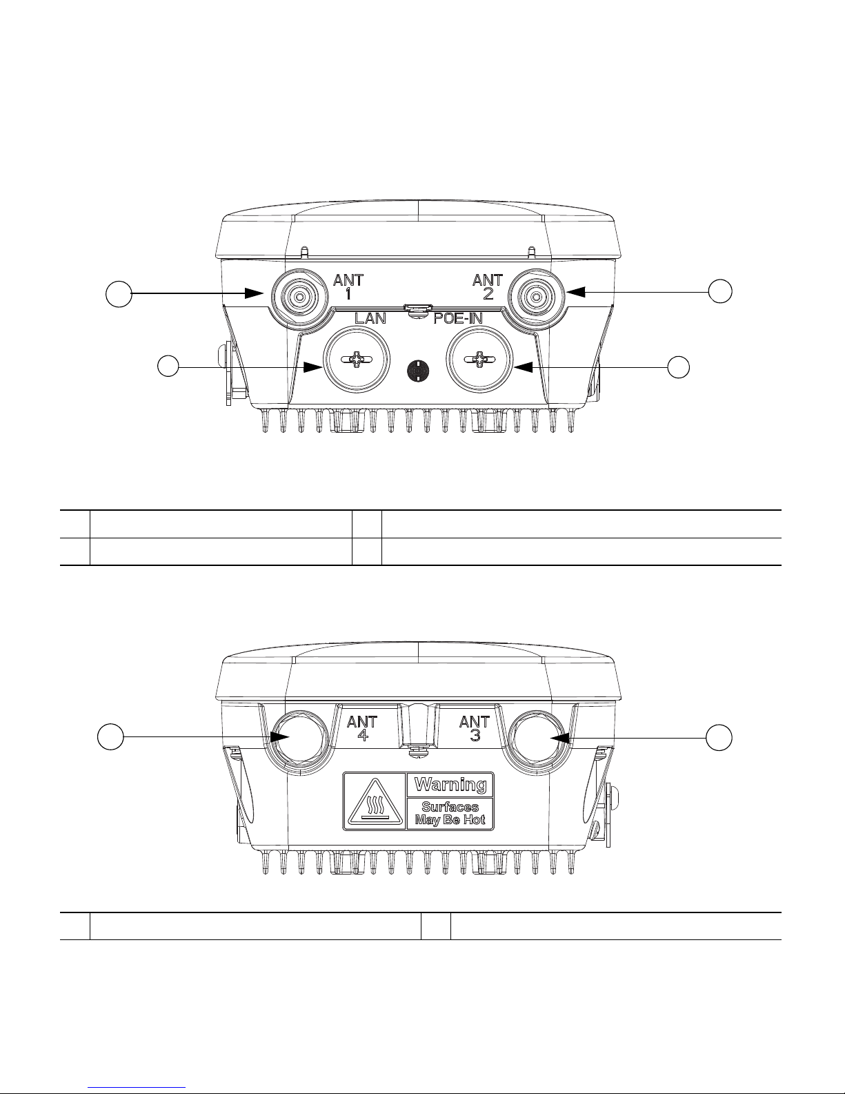
Figure 2 Access Point Bottom Connectors - AP 1532E
Figure 3 Access Point Top Connectors - AP 1532E
1 Antenna port 1 2 Antenna port 2
3 LAN port (covered) 4 PoE-in port (covered)
1 Antenna port 4 (covered) 2 Antenna port 3 (covered)
347848
1
2
4
3
347847
1
2
Page 11

11
Figure 4 Access Point Left Side Connectors - Both AP 1532 Models
Figure 5 Access Point DC Power Connector and Ground Lug (Both AP 1532 Models)
1
Console Port and Reset button (covered)
1 DC power port (covered) 2 Ground lug location
3 Barcode label
347845
1
347846
1
2
3
Page 12

12
Radio Operation and Antennas
AP 1532I
The AP 1532I uses an Integrated Low Profile Dual-Band 2.4/5 GHz Dipole Antenna Array. The
antenna contains an array of three dual-band dipole antennas. The three dipole antennas are contained
within this single radome, thereby greatly reducing the antenna’s visual footprint, and greatly reducing
the possibility of snagging the antenna on the cable bundle, the RF cable, or test cables. The antennas
operate over both 2.4 GHz and 5.25 – 5.85 GHz bands. Each of the three dipole antennas is a
dual-band antenna, covering both the 2.4 – 2.483 GHz band, and the 5.25 – 5.85 GHz bands. The
antennas have a peak gain of about 3 dBi at 2.4 GHz and 5 dBi at 5 GHz. The antenna unit is gray
weatherproof radome for outdoor operation.
The 1532I access point 802.11b/g/n radio is used primarily for local access and its 802.11a/n radio for
wireless backhaul in the Mesh.
The 2-GHz b/g/n radio operates in 2.4 GHz ISM band. It supports channels 1-11 in US, 1-13 in
Europe, and 1-13 in Japan. It has three transmitters with a maximum total output power of 29dBm
for 802.11b/g/n operation. Output power is configurable for 8 levels in 3 dB steps. It has three
receivers that enables maximum-ratio combining (MRC).
The 5 GHz a/n radio operates in the UNII-2 band (5.25 - 5.35 GHz), UNII-2 Extended/ETSI band
(5.47- 5.725 GHz), and the upper ISM band (5.725 - 5.850 GHz). It has two transmitters with a
maximum total output power of 27 dBm depending on the regulatory domain. The total maximum
output power for the upper ISM band is 27 dBm for A-domain. Tx power settings will change
depending on the regulatory domain. Output power is configurable in 3 dB steps. Its three receivers
enable maximum-ratio combining (MRC).
The 1532I access point is equipped with three integrated dual-band antennas with 3 dBi gain at 2 GHz
and 5 dBi at 5 GHz.
Warning
Do not locate the antenna near overhead power lines or other electric light or power
circuits, or where it can come into contact with such circuits. When installing the
antenna, take extreme care not to come into contact with such circuits, because they
may cause serious injury or death. For proper installation and grounding of the antenna,
please refer to national and local codes (for example, U.S.:NFPA 70, National Electrical
Code, Article 810, Canada: Canadian Electrical Code, Section 54).
Statement 1052
Warning
Only trained and qualified personnel should be allowed to install, replace, or service this
equipment.
Statement 1030
Page 13

13
AP 1532E
The 1532E is equipped with two N-type radio frequency (RF) connectors (antenna ports 1 and 2) on
the bottom of the unit for external antennas to support multiple input multiple output (MIMO)
operation in dual-band mode, as shown in Figure 6. The 1532E must always be operated with the two
external antennas attached. When using the Cisco Aironet AIR-ANT2547V-N Dual-Band
Omnidirectional Antenna, the 2.4- and 5-GHz antennas connect directly to the access point, as shown
in Figure 7. If the antennas are remotely located, an appropriate low-loss RF coax cable should be
used.
The 1532E access point are equipped with 4 N-type radio frequency (RF) connectors (antenna ports
1 and 2 on the bottom of the unit for 2-GHz and antenna ports 3 and 4 on the top of the unit for
5-GHz) for external antennas to support multiple input multiple output (MIMO) operation. The
antenna ports located of top of the 1532E are shown in Figure 3. The 1532E must always be operated
with the appropriate external antennas attached. Ports 1 and 2 can be used for Dual Band operation
with a software configuration.
Note The antenna port caps must be removed for a uni-band antenna installation, but ports 3 and
4 should remain capped for a dual-band antenna instlalation to provide an IP67 seal.
Figure 6 Access Point Bottom External Antenna Connectors - AP 1532E
1
N-Type Connector - Antenna port 1 (Tx/Rx)
2
N-Type Connector - Antenna port 2(Tx/Rx)
347848
1
2
Page 14

14
Antenna Mounting Configurations
The selection of the antenna is determined in the configuration of the product. The 1532E antennas
can be mounted on a wall, pole and/or tower mounted. See Antennas, page 7 for a list of supported
antennas.
Figure 7 Access Point Dual-Band Omnidirectional Antennas - Installed Only on AP 1532E
1 Antenna connected to antenna port 1(Type-N
connector) (TX/RX)
2 Antenna connected to antenna port 2 (Type-N
connector) (TX/RX)
1
2
Page 15

15
Note The FCC limits the amount of power this device can transmit. Power transmitted is a
combination of the amplification of the signal and the antenna gain. The access point has been
designed to operate with the Cisco provided antennas.
Power
Note For detailed information on the power options available for the 1530 series access points, see
the Cisco Aironet 1530 Series Outdoor Access Point Hardware Installation Guide.
Warning
Installation of the equipment must comply with local and national electrical codes.
Statement 1074
Warning
This equipment must be externally grounded using a customer-supplied ground wire
before power is applied. Contact the appropriate electrical inspection authority or an
electrician if you are uncertain that suitable grounding is available.
Statement 366
Warning
Do not work on the system or connect or disconnect cables during periods of lightning
activity.
Statement 1001
The 1532E access point supports these power sources:
• DC power—24- 57 VDC
• Power-over-Ethernet (PoE)
Caution Do not place the power injector in an unprotected outdoor environment because water
could get into the power injector and cause a short circuit and possible fire.
Warning
Connect the unit only to DC power source that complies with the Safety Extra-Low
Voltage (SELV) requirements in IEC 60950 based safety standards
Statement 1033
Page 16

16
Power Injectors
The 1530 Series Access Points support the following power injectors:
• AIR-PWRINJ1500-2= — 100-240 VAC input, indoor use only
• AIR-PWRINJ-30= — 100-240 VAC input, indoor use only
Warning
To reduce the risk of fire, use only No. 26 AWG or larger telecommunication line cord.
Statement 1023
Caution When the access point is installed outdoors or in a wet or damp location, the AC branch
circuit that is powering the access point should be provided with ground fault protection
(GFCI), as required by Article 210 of the National Electrical Code (NEC).
Ethernet (PoE) Ports
The access point supports an Ethernet uplink port (PoE-In). The access point Ethernet uplink port uses
an RJ-45 connector (with weatherproofing) to link the access point to the 10BASE-T, 100BASE-T or
1000BASE-T network. The Ethernet cable is used to send and receive Ethernet data and to optionally
supply inline 56-VDC power from the power injector.
Tip The access point senses the Ethernet and power signals and automatically switches internal
circuitry to match the cable connections.
Warning
To reduce the risk of fire, use only No. 26 AWG or larger telecommunication line cord.
Statement 1023
The Ethernet cable must be a shielded outdoor rated Category 5e (CAT5e) or better cable. The access
point senses the Ethernet and power signals and automatically switches internal circuitry to match the
cable connections.
Page 17

17
6 AP Pole/Wall Mount
This section provides instructions for installing your access point(s). Personnel installing the access
point(s) must understand wireless access points and bridging techniques and grounding methods.
Caution All installation methods for mounting an access point on any wall surface is subject to the
acceptance of local jurisdiction.
Installation Options
Note For more installation options and detailed access point installation instructions, see the Cisco
Aironet 1530 Series Outdoor Access Point Hardware Installation Guide.
The 1530 Series Access Point can be wall, pole or tower mounted.There are two optional mounting
kits: a fixed mounting kit (AIR-ACC1530-PMK1=) and a pivoting mounting kit
(AIR-ACC1530-PMK2=).
Warning
Only trained and qualified personnel should be allowed to install, replace, or service this
equipment.
Statement 1030
Warning
Installation of the equipment must comply with local and national electric codes.
Statement 1074
When mounting an access point on a horizontal or vertical surface, you must ensure that the access
point is oriented with the LED indicators pointing down (see Figure 10 on page 33). This positioning
allows LEDs to be visible to someone on the ground below the access point.
You must also ensure the access point is mounted in such a way as to ensure that all anntenna ports
and the console port are accessible for future use.
Page 18

18
Wall Mounting the Access Point with the Fixed Mounting Kit
The optional fixed mounting kit contains a mounting bracket for wall mounting or pole mounting.
You can use the mounting bracket as a template to mark the positions of the mounting holes for your
installation. You then install the mounting plate, and attach the access point when you are ready.
Table 1 lists the materials you will need to provide in addition to the fixed mounting kit.
Table 1 Material Needed to Mount Access Point to a Vertical Wall
Caution The mounting surface, attaching screws and optional wall anchors must be able to
support a 50-lb (22.7 kg) static weight.
To mount the access point on a vertical wall, follow these instructions:
Materials Required In Kit
Ground lug and screws (provided with access point) Yes
Wall Mount Bracket Yes
Four M6 x 12-mm Hex-head Bolts Yes
Two stainless steel band clamps (adjustable 2"–5", 51 mm –
127 mm)
Yes
Two stainless steel band clamps(adjustable 5"–8", 127 mm –
203 mm)
Yes
Crimping tool for ground lug, Panduit CT-720 with CD-720-1
die (http://www.panduit.com)
No
Four wall mounting screws No
Four wall anchors (specified for all material) No
Drill bit for wall anchors No
Electric drill and standard screwdriver No
#6 AWG ground wire No
Shielded outdoor-rated Ethernet (CAT5e or better) cable with
0.20 to 0.35 inch (0.51 to 0.89 cm) diameter
No
Grounding block No
Grounding rod No
10-mm box-end wrench or socket set No
Page 19

19
Step 1 Use the mounting bracket as a template to mark four screw hole locations on the mounting
surface. See Figure 8 for the mounting bracket screw hole locations. Use the bracket mount
holes to attach the unit to the wall.
Figure 8 Mounting Bracket for Wall or Pole Mounting
Step 2 Use four customer-supplied screws and optional screw-anchors to attach the mounting plate
to the mounting surface.
Note If necessary, use suitable screw anchors and an exterior-grade plywood backboard to mount
the access point to stucco, cement or drywall.
Step 3 Screw an M6 x12 mm bolt into each of the four support bolt holes on the back of the access
point. Do not screw the bolt all the way in; leave approximately a 0.13 inch (3.3 mm) space.
Step 4 Position the four bolts on the access point into the keyhole slots on the mounting bracket.
1 Quick Mount Keyhole Slots (for AP use) 2 Mounting Slots (used with the band clamps)
3 Bracket Mount Holes (use bolts up to 1/4" or
6 mm in diameter)
347852
1
2
3
Page 20

20
Step 5 Slide the access point down to sit securely in the quick mount slots.
Step 6 Using a 10mm wrench, secure the AP to the bracket by tighening the bolts to the bracket;
torque to 40 in-lbf.
Step 7 Continue with the Grounding the Access Point, page 23.
Pole Mounting the Access Point with the Fixed Mount Kit
The optional fixed mounting kit contains a mounting bracket for wall mounting or pole mounting.This
kit can be used to install the access point on a pole, mast or streetlight. It supports metal, wood or
fiberglass poles from 2 to 8 inches in diameter.
Table 2 Materials Needed to Mount the AP on a Vertical Pole
To mount the access point onto a vertical pole or streetlight pole, follow these steps:
Step 1 Select a mounting location on the pole to mount the access point. You can attach the access
point to any pole with a diameter from 2to 8 inches (5.1 to 20.1 cm).
Materials Required In Kit
One wall mount bracket Yes
Four M6 x12mm hex head bolts Yes
Two stainless steel band clamps (adjustable 2"–5", 51–127
mm)
Yes
Two stainless steel band clamps (adjustable 5"–8", 127–203
mm)
Yes
10 mm box-end wrench No
Outdoor rated shielded ethernet cable match Ethernet cable
description for Table #1. Include 0.20 to 0.35 inch (0.51 to
0.89 cm) diameter specification.
No
Ground lug (provided with the access point) Yes
Ground block and rod No
Crimping tool for ground lug, Panduit CT-720 with CD-720-1
die (http://www.panduit.com)
No
#6 AWG ground wire No
Page 21

21
Note If you will be using a streetlight power tap adapter, position the access point within
3 ft (1 m) of the outdoor light control. The AC/DC adapter must be used with street
light power tap.
Step 2 Determine which size of band clamp is needed based on the pole diameter. Slide the two
clamps through the top and bottom set of of mounting slots (see Figure 9) and mount the
bracket to the pole.
Step 3 Wrap the band clamps around the pole and slide them into the second set of top and bottom
mounting slots on the bracket. Lightly tighten the clamps. Only tighten them enough to keep
the bracket from sliding down the pole.
Step 4 Screw an M6 bolt into each of the four bolt holes on the back side of the access point. Do not
screw the bolt in all the way. Leave a gap of about 0.13" (3.3mm).
Step 5 Position the four bolts on the access point into the bracket keyhole slots. Check to be sure that
the access point is properly seated in the slots.(See Figure 9)
Note The access point should be positioned with the LEDs on the bottom to allow viewing
from the ground.
Step 6 Using a 10mm wrench, tighten the four bolts that connect the access point to the bracket to
a torque of 40 in-lbf.
Step 7 Locate the access point to its final position. Tighten the band clamps with the wrench so that
the access point does not slide on the pole. Be sure that the clamps are tight enough that the
AP does not move.
Step 8 Continue with the Grounding the Access Point, page 23.
Page 22

22
Figure 9 AP and Fixed Mount Kit Installed on a Pole
1 Metal Band Strap 2 Mounting Slots
3 Pole
351492
1
2
3
Page 23

23
Grounding the Access Point
The access point must be grounded before connecting power.
Warning
This equipment must be externally grounded using a customer-supplied ground wire
before power is applied. Contact the appropriate electrical inspection authority or an
electrician if you are uncertain that suitable grounding is available.
Statement 366
Warning
Installation of the equipment must comply with local and national electrical codes.
Statement 1074
In all outdoor installations and when powering the access point with AC power, you must follow these
instructions to properly ground the access point:
Step 1 If using insulated 6-AWG copper ground wire, strip the insulation as required for the
grounding lug.
Step 2 Use the appropriate crimping tool to crimp the bare 6-AWG copper ground wire to the
supplied grounding lug.
Note The grounding lug and hardware used must comply with local and national electrical
codes.
Step 3 Open the electrical joint compound (supplied), and apply a liberal amount over the metal
surface where the ground strap screw holes are located (see Figure 5).
Step 4 Connect the grounding lug to the access point grounding screw holes (see Figure 5) using the
supplied two Phillips head screws (M4 x 10 mm) with lock washers. Tighten the grounding
screw to 22 to 24 in. lbs (2.49 to 2.71 Nm).
Step 5 If necessary, strip the other end of the ground wire and connect it to a reliable earth ground,
such as a grounding rod or an appropriate grounding point on a metal streetlight pole that is
grounded.
Page 24

24
7 Preparing the Access Point
The access point is a radio device which is susceptible to common causes of interference that can
reduce throughput and range. Follow these basic guidelines to ensure the best possible performance:
• For information on planning and initially configuring your Cisco mesh network, refer to the Cisco
Wireless Mesh Access Points, Design and Deployment Guide, Release 7.6. These documents are
available on Cisco.com.
• Do not install the access point in an area where structures, trees, or hills obstruct radio signals to
and from the access point.
• You can install the access point at any height, but best throughput is achieved when the access
points are mounted at the same height.
Note To perform path loss calculation and to determine how far apart to install access points,
consult an RF planning expert.
Note For information on conducting a site survey prior to installing the access point, see the Cisco
Aironet 1530 Series Outdoor Access Point Hardware Installation Guide.
Avoiding Damage to Radios in a Testing Environment
The radios on outdoor units (bridges) have higher transmit power levels than radios on indoor units
(access points). When you test radios in a link, you must avoid exceeding the maximum receive input
level of the receiver. At levels higher than the normal operating range and packet error rate (PER)
performance of the receiver is degraded. At even higher levels, the receiver can be permanently
damaged.
To avoid receiver damage and PER degradation, you can use one of the following techniques:
• Separate the omnidirectional antennas by at least 2 ft (0.6 m) to avoid receiver damage or by at
least 25 ft (7.6 m) to avoid PER degradation.
• Reduce the configured transmit power to the minimum level.
• Cable the radios together using a combination of attenuators, combiners, or splitters to achieve a
total attenuation of at least 60 dB.
Page 25

25
For a radiated test bed, the following equation describes the relationships among transmit power,
antenna gain, attenuation, and receiver sensitivity:
txpwr + tx antenna gain + rx ant gain - [attenuation due to antenna spacing] < max rx
input level
Where:
txpwr = Radio transmit power level
tx gain = transmitter antenna gain
rx gain = receiver antenna gain
For a conducted test bed, the following equation describes the relationships among transmit power,
antenna gain, and receiver sensitivity:
txpwr - [attenuation due to coaxial RF Attenuator components] < max rx input level
(0 dbm)
Caution Under no circumstances should you connect the antenna port from one access point to the
antenna port of another access point without using an RF attenuator. If you connect
antenna ports you must not exceed the maximum survivable receive level of 0 dBm. Never
exceed 0 dBm or damage to the access point can occur. Using attenuators, combiners, and
splitters having a total of at least 60 dB of attenuation ensures that the receiver is not
damaged and PER performance is not degraded.
Before You Begin
Warning
Read the installation instructions before connecting the system to the power source.
Statement 1004
Before you begin the installation process:
• Become familiar with the procedures for mounting the access point (see the AP Pole/Wall Mount,
page 17).
• Become familiar with the access point connections (Figure 1 on page 9, Figure 4 on page 11, and
Figure 5 on page 11).
• Verify that the switch you are using to connect the controller is configured properly.
Page 26

26
8 Deploying the Access Point
The following portions of this manual address how to deploy the Access Point. There are several
deployment methods.
Warning
Do not operate the unit near unshielded blasting caps or in an explosive environment
unless the device has been modified to be especially qualified for such use.
Statement 364
Controller-based Deployments
The access point is deployed on Layer 3 networks. Layer 3 is the default mode for a newly configured
wireless LAN controller. This guide assumes that you will be deploying your access point on a Layer
3 network and a DHCP server is available.
Before deploying the access point, make sure the controller to which the access point will associate is
properly configured by performing the following operations:
• Verify the wireless LAN controller software version
• Record the access point BVI MAC address (MAC address is located on the label on the side of the
unit.)
• Enter the access point BVI MAC address to the wireless LAN controller filter list
Recording the Access Point MAC Address
Use a text file to record the MAC address of all the access points you intend to deploy in your network.
Having a file of the access point MAC addresses will be of considerable value for future testing. While
you are compiling the list, you might want to change the name of the access point to something you
can easily remember. The name can contain up to 32 characters. The following example,
fisher_street:ea:co contains the last four HEX characters of the access point MAC address.
Page 27

27
Adding the Access Point MAC Address to the Wireless LAN Controller
Filter List
The wireless LAN controller maintains an access point authorization MAC address list and responds
to discovery requests from access points on that list. To add the access point MAC address (or MAC
addresses) to the Wireless LAN controller filter list, follow these steps:
Step 1 If you are not logged onto the wireless LAN controller, log on now. The Summary page
appears.
Step 2 On the menu bar, click SECURITY. The Security RADIUS Authentication Server page
appears.
Step 3 Under AAA in the left frame, click MAC Filtering. The Security MAC Filtering page appears.
Step 4 Click New. The MAC Filters New page appears.
Step 5 Enter the MAC address of the access point in the MAC Address field. You can also use the
config macfilter add command to add a MAC filter entry to the controller.
Step 6 Select a WLAN ID or Any WLAN from the WLAN ID pop-up menu.
Step 7 Enter a description (32 characters maximum) of the access point in the Description field.
Step 8 Choose an interface from the Interface Name pop-up menu.
Step 9 Click Apply.
Step 10 Repeat this process to add other access points to the list.
Note You can also use the controller CLI command config macfilter add to add a MAC
filter entry on the controller.
Step 11 On the menu bar, click Monitor to return to the Monitor Summary page.
Verifying Controller Association
To verify that your access point is associated to the wireless LAN controller, perform these steps:
Step 1 Log into your controller web interface (https) using a web browser.
Step 2 Click Wireless and verify that your access point MAC address is listed under Ethernet MAC.
Step 3 Log out of the controller and close your web browser.
Page 28

28
Deployment Notes
Using a DHCP Server in a Layer 3 Mesh Network
To use a DHCP server in a Layer 3 mesh network, you must configure DHCP option 43 on the DHCP
server. After the controller is restarted, the access point receives IP addresses from the DHCP server.
Configuring DHCP Option 43
You can use DHCP Option 43 to provide a list of controller IP addresses to the access points, enabling
each access point to find and join a controller. This section contains a DHCP Option 43 configuration
example on a Microsoft Windows 2003 Enterprise DHCP server for use with Cisco Aironet
lightweight access points.
Additional information about Microsoft DHCP Option 43 is available on Cisco.com at the following
URL:
http://www.cisco.com/en/US/tech/tk722/tk809/technologies_configuration_example09186a0080871
4fe.shtml
DHCP Option 43 server implementation information for Cisco IOS is available at cisco.com at the
following URL:
http://www.cisco.com/en/US/docs/wireless/technology/controller/deployment/guide/dep.html#wp106
8287
Note In DHCP Option 43, you should use the IP address of the controller management interface.
Note DHCP Option 43 is limited to one access point type per DHCP pool. You must configure a
separate DHCP pool for each access point type.
Cisco 1532 access points use the type-length-value (TLV) format for DHCP Option 43. DHCP servers
must be programmed to return the option based on the DHCP Vendor Class Identifier (VCI) string
(DHCP Option 60) of the access point. The VCI string for the Cisco 1532 access point is
Cisco AP c1530.
The format of the TLV block for the 1532 access point is listed below:
• Type: 0xf1 (decimal 241)
• Length: Number of controller IP addresses * 4
• Value: List of WLC management interfaces
Page 29

29
Configuring Option 43 for Cisco 1532 Access Points
To configure DHCP Option 43 for Cisco 1532 access point in the embedded Cisco IOS DHCP server, follow
these steps:
Step 1 Enter configuration mode at the Cisco IOS CLI.
Step 2 Create the DHCP pool, including the necessary parameters such as default router and name server.
The commands used to create a DHCP pool are as follows:
ip dhcp pool pool name
network IP Network Netmask
default-router Default router
dns-server DNS Server
Where:
pool name is the name of the DHCP pool, such as AP1532.
IP Network is the network IP address where the controller resides, such as
10.0.15.1
Netmask is the subnet mask, such as 255.255.255.0
Default router is the IP address of the default router, such as 10.0.0.1
DNS Server is the IP address of the DNS server, such as 10.0.10.2
Step 3 Add the Option 60 line using the following syntax:
option 60 ascii “VCI string”
For the VCI string, use the value from Configuring DHCP Option 43, page 28. The quotation
marks must be included.
Step 4
Add the option 43 line using the following syntax:
option 43 hex hex string
The hex string is assembled by concatenating the TLV values shown below:
Type + Length + Value
Type is always f1(hex). Length is the number of controller management IP addresses times 4
in hex. Value is the IP address of the controller listed sequentially in hex.
For example, suppose that there are two controllers with management interface IP addresses,
10.126.126.2 and 10.127.127.2. The type is f1(hex). The length is 2 * 4 = 8 = 08 (hex). The
IP addresses translate to 0a7e7e02 and 0a7f7f02. Assembling the string then yields
f1080a7e7e020a7f7f02. The resulting Cisco IOS command added to the DHCP scope is listed
below:
option 43 hex f1080a7e7e020a7f7f02
Page 30

30
Autonomous Mode Configuration
The 1530 Series allows the Unified (controller-based) and Autonomous mode software to be loaded at
the factory on the same hardware part number. This eliminates the need for separate part numbers for
controller-based units and autonomous mode units.
At boot-up, the default mode is controller-based. The 1530 will power up and begin searching for a
controller. Once it joins the controller, it will download the active Unified image from the controller.
This is the same operation as other Cisco controller-based APs.
For Autonomous mode, the user should take the following steps:
Step 1 Power the AP and connect to the console.
Step 2 From the Command Line, enter:
AP # capwap ap autonomous (# means privileged EXEC mode)
Step 3 The system will respond with "Convert to Autonomous image. Proceed? (yes/[No]):"
Step 4 Type "yes" to confirm.
Step 5 The AP will then re-boot and load the Autonomous image. The unified image is erased.
Step 6 Once the 1530 has booted in autonomous mode, configuration of the AP can done by
following the procedure outlined here:
http://www.cisco.com/c/en/us/td/docs/wireless/access_point/15-3-3/configuration/guide/cg153-3.html
Page 31

31
9 In Case of Difficulty
Help is available from Cisco should you experience difficulties; however, before contacting Cisco, look
for a solution to your problem in the following places:
• The Troubleshooting section of this guide
• The Troubleshooting a Mesh Network troubleshooting guide found on cisco.com at
http://www.cisco.com/en/US/products/ps8368/prod_troubleshooting_guides_list.html
• The Tools and Resources section on the Technical Support and Documentation page at cisco.com
Follow these steps to contact the Technical Assistance Center on cisco.com:
Step 1 Open your browser and go to http://www.cisco.com/.
Step 2 Click Support. The Support page appears.
Step 3 Choose the link that best serves your support requirements.
Note Click My Tech Support if you are a registered user.
Step 4 Follow the instructions on the page.
Troubleshooting
Caution No serviceable parts inside. Do not open.
This section provides troubleshooting procedures for basic problems with the access point. For the
most up-to-date, detailed troubleshooting information, refer to the Cisco Support website at
cisco.com.
Page 32

32
Guidelines for Using the Access Point
You should keep these guidelines in mind when you use the access point:
• The access point supports Layer 3 CAPWAP communications with the controllers. In Layer 3
operation, the access point and the controller can be on the same or different subnets. The access
point communicates with the controller using standard IP packets. Layer 3 operation is scalable
and is recommended by Cisco. Unless it has a static IP address, a Layer 3 access point on a different
subnet than the controller requires a DHCP server on the access point subnet and a route to the
controller. The route to the controller must have destination UDP ports 12222 and 12223 open
for CAPWAP communications. The routes to the primary, secondary, and tertiary controllers must
allow IP packet fragments.
• Before deploying your mesh access points ensure that the following has been done:
–
Your controllers are connected to switch ports that are configured as trunk ports.
–
Your mesh access points are connected to switch ports that are configured as untagged access
ports.
–
A DHCP server is reachable by your mesh access points and has been configured with Option
43. Option 43 is used to provide the IP addresses of the Management Interfaces of your
controllers. Typically, a DHCP server can be configured on a Cisco Layer 3 switch or router.
–
Optionally a DNS server can be configured to enable a local domain Cisco CAPWAP
controller (CISCO-CAPWAP-CONTROLLER.<local domain>) to resolve to the IP address of
the Management Interface of your controller.
–
Your controllers are configured and reachable by the mesh access points.
–
Your controllers are configured with the MAC addresses of the mesh access points.
Page 33

33
Checking the LEDs
One LED is located between the LAN and PoE-In connectors. It indicates the status of the access point
power, uplinks and radios. Figure 10 identifies and describes the LED functions. Table 3 provides
additional LED signal information.
Figure 10 Access Point LEDs –Shown on the Bottom of AP 1532E
Table 3 Access Point LED Signals
LED Message
Type
Color Meaning
Boot loader
status sequence
Blinking Green Boot loader status sequence:
• DRAM memory test in progress
• DRAM memory test OK
• Board initialization in progress
• Initializing FLASH file system
• FLASH memory test OK
• Initializing Ethernet
• Ethernet OK
• Starting Cisco IOS
• Initialization successful
347848
LED
Indicator
Page 34

34
Boot loader
warnings
Blinking Amber Configuration recovery is in progress (the MODE button
has been pushed for 2-3 seconds)
Solid Red There is an Ethernet failure or an image recovery (the
MODE button has been pushed for 20-30 seconds)
Blinking Green An image recovery is in progress (the MODE button has
been released)
Boot loader
errors
Solid Red There has been a DRAM memory test failure
Blinking Red and Amber There has been a FLASH file system failure
Blinking Red and Off This sequence may indicate any of the following:
• Environment variable failure
• Bad MAC address
• Ethernet failure during image recovery
• Boot environment failure
• No Cisco image file
• Boot failure
Cisco IOS
errors
Solid Red There has been a software failure; a disconnect then
reconnect of the unit power may resolve the issue
Cycling through Red,
Green, Amber and Off
This is a general warning of insufficient inline power.
Association
status
Chirping (short blips)
Green
This status indicates a normal operating condition. The
unit is joined to a controller, but no wireless client is
associated with it.
Solid Green Normal operating condition with at least one wireless
client associated with the unit
LED Message
Type
Color Meaning
Page 35

35
Note Regarding LED status colors, it is expected that there will be small variations in color intensity
and hue from unit to unit. This is within the normal range of the LED manufacturer’s
specifications and is not a defect.
Operating
Status
Blinking Amber A software upgrade is in progress
Cycling through Green,
Red and Amber
Discovery/join process is in progress
Rapidly cycling through
Red, Green, Amber and
Off
This status indicates that the Access Point location
command has been invoked.
Blinking Red This status indicates that an Ethernet link is not
operational
Alignment
Mode
Color Signal Level (dBm)
Solid Green > –44
Fast blinking Green –47 to –44
Medium blinking Green –50 to –47
Solid Amber –53 to –50
Fast blinking Amber –57 to –53
Medium blinking Amber –60 to –57
Slow blinking Amber –63 to –60
Slow blinking Red –66 to –63
Medium blinking Red –69 to –66
Fast blinking Red –72 to –69
Solid Red –75 to –72
Off < –75
LED Message
Type
Color Meaning
Page 36

Misconfigured Access Point IP address
IP address misconfiguration can occur when you are re-addressing a segment of your mesh network
and you start at the mesh access point connected to the wired network (RAP). To avoid this problem,
always start the IP address changes from the farthest access point and work your way back to the root
access point. This problem might also happen if you move equipment such as uninstalling amesh access
point and then redeploying with a different IP subnet in another physical location on the mesh
network.
Another option to fix this misconfigured IP address is to physically take a controller in Layer 3 mode
with a root access point to the location of the misconfigured mesh access point. Set the bridge group
name for the root access point to match the misconfigured access point. Add the access point MAC
address to the filter list of the controller. When the misconfigured access point appears in the Summary
page of the controller, configure the access point with an IP address.
If you are using a static IP address on the access point and plan on redeploying the access point on
another subnet, perform a clear config command from the controller for that access point while it is
joined before you remove it from the network.
Verifying the Controller MAC Filter List
Prior to activating your access point, you must ensure that the access point MAC address has been
added to the controller MAC Filter list and that Mac Filter List is enabled. To view the MAC addresses
added to the controller MAC filter list and ensure the MAC filter list is enabled, you can use the
controller CLI or the controller GUI.
Controller CLI
Use the show macfilter summary controller CLI command to view the MAC addresses added to the
controller filter list.
Controller GUI
Log into your controller web interface (HTTPS) using a web browser and click SECURITY > AAA >
MAC Filtering to view the MAC addresses added to the controller filter list. Then click Wireless >
Mesh to ensure the MAC filter list is enabled.
Page 37

37
10 Declarations of Conformity and Regulatory Information
For the declarations of conformity and regulatory information for the Cisco 1532 Access Point, see
the Appendix Declarations of Conformity and Regulatory Information in the Cisco Aironet 1530
Series Outdoor Access Point Hardware Installation Guide.
11 Warranty
Cisco Aironet 1530 Series Outdoor Mesh Access Points come with a one-year warranty. For more
details, visit http://www.cisco.com/go/warranty, and look up the 1530 series access points in the
Warranty Finder tool.
Page 38

38
Page 39

39
Page 40

Cisco and the Cisco logo are trademarks or registered trademarks of Cisco and/or its affiliates in the U.S. and other countries. To view a list of
Cisco trademarks, go to this URL: www.cisco.com/go/trademarks. Third-party trademarks mentioned are the property of their respective owners.
The use of the word partner does not imply a partnership relationship between Cisco and any other company. (1110R)
© 2013 Cisco Systems, Inc. All rights reserved.
Printed in the USA on recycled paper containing 10% postconsumer waste.
78-21473-01
Americas Headquarters
Cisco Systems, Inc.
San Jose, CA
Asia Pacific Headquarters
Cisco Systems (USA) Pte. Ltd.
Singapore
Europe Headquarters
Cisco Systems International BV Amsterdam,
The Netherlands
Cisco has more than 200 offices worldwide. Addresses, phone numbers, and fax numbers are listed on the
Cisco Website at www.cisco.com/go/offices.
 Loading...