

Cisco Aironet 1040, Aironet 1240, Aironet 1130, Aironet 1140, Aironet 1250 Deployment Manual
...Page 1

Cisco Mesh Access Points, Design and Deployment Guide, Release
7.3
First Published: August 28, 2012
Americas Headquarters
Cisco Systems, Inc.
170 West Tasman Drive
San Jose, CA 95134-1706
USA
http://www.cisco.com
Tel: 408 526-4000
800 553-NETS (6387)
Fax: 408 527-0883
Text Part Number: OL-27593-01
Page 2

THE SPECIFICATIONS AND INFORMATION REGARDING THE PRODUCTS IN THIS MANUAL ARE SUBJECT TO CHANGE WITHOUT NOTICE. ALL STATEMENTS,
INFORMATION, AND RECOMMENDATIONS IN THIS MANUAL ARE BELIEVED TO BE ACCURATE BUT ARE PRESENTED WITHOUT WARRANTY OF ANY KIND,
EXPRESS OR IMPLIED. USERS MUST TAKE FULL RESPONSIBILITY FOR THEIR APPLICATION OF ANY PRODUCTS.
THE SOFTWARE LICENSE AND LIMITED WARRANTY FOR THE ACCOMPANYING PRODUCT ARE SET FORTH IN THE INFORMATION PACKET THAT SHIPPED WITH
THE PRODUCT AND ARE INCORPORATED HEREIN BY THIS REFERENCE. IF YOU ARE UNABLE TO LOCATE THE SOFTWARE LICENSE OR LIMITED WARRANTY,
CONTACT YOUR CISCO REPRESENTATIVE FOR A COPY.
The Cisco implementation of TCP header compression is an adaptation of a program developed by the University of California, Berkeley (UCB) as part of UCB's public domain version
of the UNIX operating system. All rights reserved. Copyright©1981, Regents of the University of California.
NOTWITHSTANDINGANY OTHER WARRANTY HEREIN, ALL DOCUMENT FILES AND SOFTWARE OF THESE SUPPLIERS ARE PROVIDED “AS IS" WITH ALL FAULTS.
CISCO AND THE ABOVE-NAMED SUPPLIERS DISCLAIM ALL WARRANTIES, EXPRESSED OR IMPLIED, INCLUDING, WITHOUT LIMITATION, THOSE OF
MERCHANTABILITY, FITNESS FOR A PARTICULAR PURPOSE AND NONINFRINGEMENT OR ARISING FROM A COURSE OF DEALING, USAGE, OR TRADE PRACTICE.
IN NO EVENT SHALL CISCO OR ITS SUPPLIERS BE LIABLE FOR ANY INDIRECT, SPECIAL, CONSEQUENTIAL, OR INCIDENTAL DAMAGES, INCLUDING, WITHOUT
LIMITATION, LOST PROFITS OR LOSS OR DAMAGE TO DATA ARISING OUT OF THE USE OR INABILITY TO USE THIS MANUAL, EVEN IF CISCO OR ITS SUPPLIERS
HAVE BEEN ADVISED OF THE POSSIBILITY OF SUCH DAMAGES.
Cisco and the Cisco logo are trademarks or registered trademarks of Cisco and/or its affiliates in the U.S. and other countries. To view a list of Cisco trademarks, go to this URL: http://
www.cisco.com/go/trademarks. Third-party trademarks mentioned are the property of their respective owners. The use of the word partner does not imply a partnership
relationship between Cisco and any other company. (1110R)
Any Internet Protocol (IP) addresses used in this document are not intended to be actual addresses. Any examples, command display output, and figures included in the document are shown
for illustrative purposes only. Any use of actual IP addresses in illustrative content is unintentional and coincidental.
©
2012 Cisco Systems, Inc. All rights reserved.
Page 3

CONTENTS
Preface
CHAPTER 1
Preface xi
Audience xii
Organization xii
Conventions xii
Related Documentation xv
Obtaining Documentation and Submitting a Service Request xv
Mesh Network Components 1
Mesh Access Points 1
Licensing for Mesh Access Points on a 5500 Series Controller 1
Access Point Roles 2
Network Access 3
Network Segmentation 4
Cisco Indoor Mesh Access Points 4
Cisco Outdoor Mesh Access Points 5
Cisco Aironet 1552 Mesh Access Point 6
Cisco 1522 Mesh Access Point 11
Cisco 1524PS Mesh Access Point 11
Cisco 1524SB Mesh Access Point 12
Ethernet Ports 14
Multiple Power Options 14
Battery Backup Module (Optional) 16
Reset Button 17
Resetting Access Point 18
Monitoring the LED Status 18
Serial Backhaul Access Point Guidelines for the Rest of the World (ROW) 21
Discontinuation of the 116 and 132 Channels from the UNII-2 Extended Band 23
OL-27593-01 iii
Cisco Mesh Access Points, Design and Deployment Guide, Release 7.3
Page 4

Contents
Frequency Bands 24
Dynamic Frequency Selection 25
Antennas 26
Antenna Configurations for 1552 31
Client Access Certified Antennas (Third-Party Antennas) 34
Maximum Ratio Combining 34
Cisco 1500 Hazardous Location Certification 37
Cisco Wireless LAN Controllers 40
Cisco Prime Infrastructure 40
Architecture 40
Control and Provisioning of Wireless Access Points 40
CAPWAP Discovery on a Mesh Network 40
Dynamic MTU Detection 41
CHAPTER 2
XML Configuration File 41
Adaptive Wireless Path Protocol 42
Traffic Flow 43
Mesh Neighbors, Parents, and Children 44
Criteria to Choose the Best Parent 45
Ease Calculation 45
Parent Decision 45
SNR Smoothing 46
Loop Prevention 46
Mesh Deployment Modes 47
Wireless Mesh Network 47
Wireless Backhaul 47
Universal Access 48
Point-to-Multipoint Wireless Bridging 48
Point-to-Point Wireless Bridging 48
Configuring Mesh Range (CLI) 49
Assumptions for the AP1522 Range Calculator 50
Assumptions for the AP1552 Range Calculator 50
CHAPTER 3
Design Considerations 51
Wireless Mesh Constraints 51
Cisco Mesh Access Points, Design and Deployment Guide, Release 7.3
iv OL-27593-01
Page 5

Contents
Wireless Backhaul Data Rate 51
ClientLink Technology 55
Configuring ClientLink (CLI) 56
Commands Related to ClientLink 58
Controller Planning 58
CHAPTER 4
Site Preparation and Planning 61
Site Survey 61
Pre-Survey Checklist 61
Outdoor Site Survey 62
Determining a Line of Sight 62
Weather 63
Fresnel Zone 63
Fresnel Zone Size in Wireless Mesh Deployments 64
Hidden Nodes Interference 65
Functional Routing of Three Radio MAPs 66
Slot Bias Options 66
Disabling Slot Bias 67
Commands Related to Slot Bias 67
Preferred Parent Selection 68
Preferred Parent Selection Criteria 68
Configuring a Preferred Parent 69
Related Commands 69
Co-Channel Interference 70
Wireless Mesh Network Coverage Considerations 71
Cell Planning and Distance 71
Assumptions for the AP1522 Range Calculator 83
Assumptions for the AP1552 Range Calculator 84
Collocating Mesh Access Points 86
Special Considerations for Indoor Mesh Networks 87
Wireless Propagation Characteristics 89
CleanAir 89
CleanAir AP Modes of Operation 90
Pseudo MAC (PMAC) and Merging 91
Event Driven Radio Resource Management and Persistence Device Avoidance 92
OL-27593-01 v
Cisco Mesh Access Points, Design and Deployment Guide, Release 7.3
Page 6

Contents
CleanAir Access Point Deployment Recommendations 92
CleanAir Advisor 93
Enabling CleanAir 94
Licensing 94
Wireless Mesh Mobility Groups 94
Multiple Controllers 95
Increasing Mesh Availability 95
Multiple RAPs 96
Indoor Mesh Interoperability with Outdoor Mesh 97
CHAPTER 5
Connecting the Cisco 1500 Series Mesh Access Points to the Network 99
Adding Mesh Access Points to the Mesh Network 100
Adding MAC Addresses of Mesh Access Points to MAC Filter 101
Adding the MAC Address of the Mesh Access Point to the Controller Filter List
(GUI) 101
Adding the MAC Address of the Mesh Access Point to the Controller Filter List
(CLI) 102
Defining Mesh Access Point Role 102
General Notes about MAP and RAP Association With The Controller 102
Configuring the AP Role (GUI) 103
Configuring the AP Role (CLI) 104
Configuring Multiple Controllers Using DHCP 43 and DHCP 60 104
Backup Controllers 105
Configuring Backup Controllers (GUI) 106
Configuring Backup Controllers (CLI) 107
Configuring External Authentication and Authorization Using a RADIUS Server 109
Configuring RADIUS Servers 110
Adding a Username to a RADIUS Server 111
Enabling External Authentication of Mesh Access Points (GUI) 112
Enable External Authentication of Mesh Access Points (CLI) 112
View Security Statistics (CLI) 113
Configuring Global Mesh Parameters 113
Configuring Global Mesh Parameters (GUI) 113
Configuring Global Mesh Parameters (CLI) 116
Viewing Global Mesh Parameter Settings (CLI) 117
Cisco Mesh Access Points, Design and Deployment Guide, Release 7.3
vi OL-27593-01
Page 7

Contents
Universal Client Access 118
Configuring Universal Client Access (GUI) 119
Configuring Universal Client Access (CLI) 119
Universal Client Access on Serial Backhaul Access Points 119
Configuring Extended Universal Access (GUI) 120
Configuring Extended Universal Access (CLI) 122
Configuring Extended Universal Access from Cisco Prime Infrastructure 123
Configuring Local Mesh Parameters 124
Configuring Wireless Backhaul Data Rate 124
Configuring Ethernet Bridging 131
Enabling Ethernet Bridging (GUI) 133
Configuring Bridge Group Names 133
Configuring Bridge Group Names (CLI) 134
Verifying Bridge Group Names (GUI) 134
Configuring Public Safety Band Settings 134
Configuring Interoperability with Cisco 3200 136
Enabling AP1522 to Associate with Cisco 3200 (GUI) 138
Enabling 1522 and 1524PS Association with Cisco 3200 (CLI) 138
Configuring Power and Channel Settings 139
Configuring Power and Channel Settings (GUI) 139
Configuring the Channels on the Serial Backhaul (CLI) 140
Configuring Antenna Gain 141
Configuring Antenna Gain (GUI) 141
Configuring Antenna Gain (CLI) 141
Backhaul Channel Deselection on Serial Backhaul Access Point 141
Configuring Backhaul Channel Deselection (GUI) 142
Configuring Backhaul Channel Deselection (CLI) 143
Backhaul Channel Deselection Guidelines 146
Configuring Dynamic Channel Assignment 147
Configuring Advanced Features 149
Using the 2.4-GHz Radio for Backhaul 150
Configuring Ethernet VLAN Tagging 151
Ethernet Port Notes 152
Ethernet VLAN Tagging Guidelines 153
VLAN Registration 154
OL-27593-01 vii
Cisco Mesh Access Points, Design and Deployment Guide, Release 7.3
Page 8

Contents
Enabling Ethernet VLAN Tagging (GUI) 155
Configuring Ethernet VLAN Tagging (CLI) 156
Viewing Ethernet VLAN Tagging Configuration Details (CLI) 156
Workgroup Bridge Interoperability with Mesh Infrastructure 157
Configuring Workgroup Bridges 158
Guidelines for Configuration 161
Configuration Example 162
WGB Association Check 164
Link Test Result 166
WGB Wired/Wireless Client 167
Client Roaming 168
WGB Roaming Guidelines 168
Configuration Example 169
Troubleshooting Tips 170
Configuring Voice Parameters in Indoor Mesh Networks 170
Call Admission Control 171
Quality of Service and Differentiated Services Code Point Marking 171
Guidelines For Using Voice on the Mesh Network 176
Voice Call Support in a Mesh Network 178
Viewing the Voice Details for Mesh Networks (CLI) 179
Enabling Mesh Multicast Containment for Video 182
Enabling Multicast on the Mesh Network (CLI) 183
IGMP Snooping 183
Locally Significant Certificates for Mesh APs 184
Guidelines for Configuration 184
Differences Between LSCs for Mesh APs and Normal APs 185
Certificate Verification Process in LSC AP 185
Getting Certificates for LSC Feature 185
Configuring a Locally Significant Certificate (CLI) 187
LSC-Related Commands 189
Controller GUI Security Settings 191
Deployment Guidelines 192
CHAPTER 6
Checking the Health of the Network 193
Show Mesh Commands 193
Cisco Mesh Access Points, Design and Deployment Guide, Release 7.3
viii OL-27593-01
Page 9

Contents
Viewing General Mesh Network Details 194
Viewing Mesh Access Point Details 195
Viewing Global Mesh Parameter Settings 196
Viewing Bridge Group Settings 197
Viewing VLAN Tagging Settings 197
Viewing DFS Details 197
Viewing Public Safety Setting 198
Viewing Security Settings and Statistics 198
Viewing Mesh Statistics for a Mesh Access Point 199
Viewing Mesh Statistics for a Mesh Access Point (GUI) 199
Viewing Mesh Statistics for an Mesh Access Point (CLI) 202
Viewing Neighbor Statistics for a Mesh Access Point 203
CHAPTER 7
Viewing Neighbor Statistics for a Mesh Access Point (GUI) 203
Viewing the Neighbor Statistics for a Mesh Access Point (CLI) 204
Troubleshooting 207
Installation and Connections 207
Debug Commands 208
Remote Debug Commands 209
AP Console Access 209
Cable Modem Serial Port Access From an AP 210
Configuration 210
Mesh Access Point CLI Commands 212
Mesh Access Point Debug Commands 213
Defining Mesh Access Point Roles 213
Backhaul Algorithm 214
Passive Beaconing (Anti-Stranding) 215
Dynamic Frequency Selection 216
DFS in RAP 216
DFS in MAP 217
Preparation in a DFS Environment 218
Monitoring DFS 219
Frequency Planning 219
Good Signal-to-Noise Ratios 220
Access Point Placement 220
OL-27593-01 ix
Cisco Mesh Access Points, Design and Deployment Guide, Release 7.3
Page 10

Contents
Check Packet Error Rate 220
Bridge Group Name Misconfiguration 220
Misconfiguration of the Mesh Access Point IP Address 222
Misconfiguration of DHCP 223
Identifying the Node Exclusion Algorithm 223
Throughput Analysis 225
CHAPTER 8
Managing Mesh Access Points with Cisco Prime Infrastructure 227
Adding Campus Maps, Outdoor Areas, and Buildings with Cisco Prime Infrastructure 227
Adding Campus Maps 228
Adding Outdoor Areas 228
Adding a Building to a Campus Map 229
Adding Mesh Access Points to Maps with Cisco Prime Infrastructure 230
Monitoring Mesh Access Points Using Google Earth 232
Launching Google Earth in Cisco Prime Infrastructure 232
Viewing Google Earth Maps 233
Adding Indoor Mesh Access Points to Cisco Prime Infrastructure 236
Managing Mesh Access Points with Cisco Prime Infrastructure 237
Monitoring Mesh Networks Using Maps 237
Monitoring Mesh Link Statistics Using Maps 237
Monitoring Mesh Access Points Using Maps 238
Monitoring Mesh Access Point Neighbors Using Maps 239
Monitoring Mesh Health 240
Viewing Mesh Statistics for a Mesh Access Point 242
Viewing the Mesh Network Hierarchy 247
Using Mesh Filters to Modify Map Display of Maps and Mesh Links 248
Monitoring Workgroup Bridges 250
Multiple VLAN and QoS Support for WGB Wired Clients 251
Workgroup Bridge Guidelines 252
Configuring VLAN and QoS Support (CLI) 252
Workgroup Bridge Output 253
WGB Detail on Controller 255
Troubleshooting Tips 256
Viewing AP Last Reboot Reason 257
Cisco Mesh Access Points, Design and Deployment Guide, Release 7.3
x OL-27593-01
Page 11

Preface
This document provides design and deployment guidelines for the deployment of secure enterprise, campus,
and metropolitan Wi-Fi networks within the Cisco wireless mesh networking solution, a component of the
Cisco Unified Wireless Network (CUWN).
Mesh networking employs Cisco Aironet 1500 Series outdoor mesh access points and indoor mesh access
points (Cisco Aironet 1040, 1130, 1140, 1240, 1250, 1260, 3500e, 3500i, 3600e, and 3600i series access
points) along with the Cisco Wireless LAN Controller, and Cisco Prime Infrastructure to provide scalable,
central management, and mobility between indoor and outdoor deployments. Control and Provisioning of
Wireless Access Points (CAPWAP) protocol manages the connection of mesh access points to the network.
End-to-end security within the mesh network is supported by employing Advanced Encryption Standard
(AES) encryption between the wireless mesh access points and Wi-Fi Protected Access 2 (WPA2) clients.
This document also outlines radio frequency (RF) components to consider when designing an outdoor
network.
The features described in this document are for the following products:
• Cisco Aironet 1550 (1552) series outdoor 802.11n mesh access points
• Cisco Aironet 1520 (1522, 1524) series outdoor mesh access points
• Cisco Aironet 1040, 1130, 1140, 1240, 1250, 1260, 3500e, 3500i, 3600e, and 3600i series indoor mesh
access points
• Mesh features in Cisco Wireless LAN Controller
• Mesh features in Cisco Prime Infrastructure
This chapter contains the following sections:
• Audience, page xii
• Organization, page xii
• Conventions, page xii
• Related Documentation, page xv
• Obtaining Documentation and Submitting a Service Request, page xv
OL-27593-01 xi
Cisco Mesh Access Points, Design and Deployment Guide, Release 7.3
Page 12

Audience
Audience
This document is for experienced network administrators who design and deploy mesh networks and configure
and maintain Cisco mesh access points and Cisco wireless LAN controllers.
Organization
This guide is organized into these chapters:
on page 1
page 47
Preface
DescriptionChapter Title
This chapter describes the components of a mesh network.Mesh Network Components,
This chapter describes the various deployment modes of mesh access points.Mesh Deployment Modes, on
Conventions
This document uses the following conventions:
Table 1: Conventions
page 51
Site Preparation and Planning,
on page 61
Connecting the Cisco 1500
Series Mesh Access Points to
the Network, on page 99
Checking the Health of the
Network, on page 193
Managing Mesh Access Points
with Cisco Prime
Infrastructure, on page 237
This chapter describes the design considerations involved in a mesh network.Design Considerations, on
This chapter describes the implementation details and configuration
examples.
This chapter describes the procedures involved in connecting mesh access
points to a network and configuring the mesh access points.
This chapter describes the commands to enter to check the health of a mesh
network.
This chapter describes the troubleshooting information.Troubleshooting, on page 207
This chapter describes information about managing access points with Cisco
Prime Infrastructure.
italic font
Cisco Mesh Access Points, Design and Deployment Guide, Release 7.3
xii OL-27593-01
IndicationConvention
Commands and keywords and user-entered text appear in bold font.bold font
Document titles, new or emphasized terms, and arguments for which you supply
values are in italic font.
Elements in square brackets are optional.[ ]
Page 13
Preface
Conventions
IndicationConvention
{x | y | z }
[ x | y | z ]
string
!, #
Means reader take note.Note
Means the following information will help you solve a problem.Tip
Required alternative keywords are grouped in braces and separated by vertical
bars.
Optional alternative keywords are grouped in brackets and separated by vertical
bars.
A nonquoted set of characters. Do not use quotation marks around the string or
the string will include the quotation marks.
Terminal sessions and information the system displays appear in courier font.courier font
Nonprinting characters such as passwords are in angle brackets.<>
Default responses to system prompts are in square brackets.[]
An exclamation point (!) or a pound sign (#) at the beginning of a line of code
indicates a comment line.
Caution
Warning
Means reader be careful. In this situation, you might perform an action that could result in equipment
damage or loss of data.
This warning symbol means danger. You are in a situation that could cause bodily injury. Before you
work on any equipment, be aware of the hazards involved with electrical circuitry and be familiar with
standard practices for preventing accidents. (To see translations of the warnings that appear in this
publication, refer to the appendix "Translated Safety Warnings.")
DescriptionWarning Title
Waarschuwing
Dit waarschuwingssymbool betekent gevaar. U verkeert in een situatie die
lichamelijk letsel kan veroorzaken. Voordat u aan enige apparatuur gaat werken,
dient u zich bewust te zijn van de bij elektrische schakelingen betrokken risico's
en dient u op de hoogte te zijn van standaard maatregelen om ongelukken te
voorkomen. (Voor vertalingen van de waarschuwingen die in deze publicatie
verschijnen, kunt u het aanhangsel "Translated Safety Warnings" (Vertalingen
van veiligheidsvoorschriften) raadplegen.)
OL-27593-01 xiii
Cisco Mesh Access Points, Design and Deployment Guide, Release 7.3
Page 14

Conventions
Preface
DescriptionWarning Title
Varoitus
Attention
Warnung
Avvertenza
Tämä varoitusmerkki merkitsee vaaraa. Olet tilanteessa, joka voi johtaa
ruumiinvammaan. Ennen kuin työskentelet minkään laitteiston parissa, ota selvää
sähkökytkentöihin liittyvistä vaaroista ja tavanomaisista onnettomuuksien
ehkäisykeinoista. (Tässä julkaisussa esiintyvien varoitusten käännökset löydät
liitteestä "Translated Safety Warnings" (käännetyt turvallisuutta koskevat
varoitukset).)
Ce symbole d'avertissement indique un danger. Vous vous trouvez dans une
situation pouvant entraîner des blessures. Avant d'accéder à cet équipement,
soyez conscient des dangers posés par les circuits électriques et familiarisez-vous
avec les procédures courantes de prévention des accidents. Pour obtenir les
traductions des mises en garde figurant dans cette publication, veuillez consulter
l'annexe intitulée « Translated Safety Warnings » (Traduction des avis de sécurité).
Dieses Warnsymbol bedeutet Gefahr. Sie befinden sich in einer Situation, die
zu einer Körperverletzung führen könnte. Bevor Sie mit der Arbeit an irgendeinem
Gerät beginnen, seien Sie sich der mit elektrischen Stromkreisen verbundenen
Gefahren und der Standardpraktiken zur Vermeidung von Unfällen bewußt.
(Übersetzungen der in dieser Veröffentlichung enthaltenen Warnhinweise finden
Sie im Anhang mit dem Titel "Translated Safety Warnings" (Übersetzung der
Warnhinweise).)
Questo simbolo di avvertenza indica un pericolo. Si è in una situazione che può
causare infortuni. Prima di lavorare su qualsiasi apparecchiatura, occorre
conoscere i pericoli relativi ai circuiti elettrici ed essere al corrente delle pratiche
standard per la prevenzione di incidenti. La traduzione delle avvertenze riportate
in questa pubblicazione si trova nell'appendice, "Translated Safety Warnings"
(Traduzione delle avvertenze di sicurezza).
Advarsel
Aviso
¡Advertencia!
Dette varselsymbolet betyr fare. Du befinner deg i en situasjon som kan føre til
personskade. Før du utfører arbeid på utstyr, må du være oppmerksom på de
faremomentene som elektriske kretser innebærer, samt gjøre deg kjent med vanlig
praksis når det gjelder å unngå ulykker. (Hvis du vil se oversettelser av de
advarslene som finnes i denne publikasjonen, kan du se i vedlegget "Translated
Safety Warnings" [Oversatte sikkerhetsadvarsler].)
Este símbolo de aviso indica perigo. Encontra-se numa situação que lhe poderá
causar danos fisicos. Antes de começar a trabalhar com qualquer equipamento,
familiarize-se com os perigos relacionados com circuitos eléctricos, e com
quaisquer práticas comuns que possam prevenir possíveis acidentes. (Para ver
as traduções dos avisos que constam desta publicação, consulte o apêndice
"Translated Safety Warnings" - "Traduções dos Avisos de Segurança").
Este símbolo de aviso significa peligro. Existe riesgo para su integridad física.
Antes de manipular cualquier equipo, considerar los riesgos que entraña la
corriente eléctrica y familiarizarse con los procedimientos estándar de prevención
de accidentes. (Para ver traducciones de las advertencias que aparecen en esta
publicación, consultar el apéndice titulado "Translated Safety Warnings.")
Cisco Mesh Access Points, Design and Deployment Guide, Release 7.3
xiv OL-27593-01
Page 15

Preface
Related Documentation
DescriptionWarning Title
Varning
Denna varningssymbol signalerar fara. Du befinner dig i en situation som kan
leda till personskada. Innan du utför arbete på någon utrustning måste du vara
medveten om farorna med elkretsar och känna till vanligt förfarande för att
förebygga skador. (Se förklaringar av de varningar som förekommer i denna
publikation i appendix "Translated Safety Warnings" [Översatta
säkerhetsvarningar].)
Related Documentation
These documents provide complete information about the Cisco Unified Wireless Network solution:
•
Cisco Wireless LAN Controller Configuration Guide
•
Cisco Wireless LAN Controller Command Reference
•
Cisco Prime Infrastructure Configuration Guide
•
Release Notes for Cisco Wireless LAN Controllers and Lightweight Access Points
Obtaining Documentation and Submitting a Service Request
For information on obtaining documentation, submitting a service request, and gathering additional information,
see the monthly What's New in Cisco Product Documentation, which also lists all new and revised Cisco
technical documentation, at:
http://www.cisco.com/en/US/docs/general/whatsnew/whatsnew.html
Subscribe to the What's New in Cisco Product Documentation as a Really Simple Syndication (RSS) feed
and set content to be delivered directly to your desktop using a reader application. The RSS feeds are a free
service and Cisco currently supports RSS version 2.0.
OL-27593-01 xv
Cisco Mesh Access Points, Design and Deployment Guide, Release 7.3
Page 16

Obtaining Documentation and Submitting a Service Request
Preface
Cisco Mesh Access Points, Design and Deployment Guide, Release 7.3
xvi OL-27593-01
Page 17

CHAPTER 1
Mesh Network Components
This chapter describes the mesh network components.
The Cisco wireless mesh network has four core components:
• Cisco Aironet 1500 series mesh access points
Note
• Cisco Wireless LAN Controller (hereafter referred to as controller)
• Cisco Prime Infrastructure
• Mesh software architecture
This chapter contains the following sections:
• Mesh Access Points, page 1
• Cisco Wireless LAN Controllers, page 40
• Cisco Prime Infrastructure, page 40
• Architecture, page 40
Cisco Aironet 1505 and 1510 mesh access points are not supported because of their
End-of-Life status.
Mesh Access Points
Licensing for Mesh Access Points on a 5500 Series Controller
To use both mesh and nonmesh access points with a Cisco 5500 Series Controller, only the base license
(LIC-CT5508-X) is required from the 7.0 release and later releases. For more information about obtaining
and installing licenses, see the Cisco Wireless LAN Controller Configuration Guide at http://www.cisco.com/
en/US/products/ps10315/products_installation_and_configuration_guides_list.html.
OL-27593-01 1
Cisco Mesh Access Points, Design and Deployment Guide, Release 7.3
Page 18

Access Point Roles
Access Point Roles
Access points within a mesh network operate in one of the following two ways:
1
Root access point (RAP)
2
Mesh access point (MAP)
Mesh Network Components
Note
All access points are configured and shipped as mesh access points. To use an access point as a root access
point, you must reconfigure the mesh access point to a root access point. In all mesh networks, ensure that
there is at least one root access point.
While the RAPs have wired connections to their controller, the MAPs have wireless connections to their
controller.
MAPs communicate among themselves and back to the RAP using wireless connections over the 802.11a/n
radio backhaul. MAPs use the Cisco Adaptive Wireless Path Protocol (AWPP) to determine the best path
through the other mesh access points to the controller.
Cisco Mesh Access Points, Design and Deployment Guide, Release 7.3
2 OL-27593-01
Page 19
Mesh Network Components
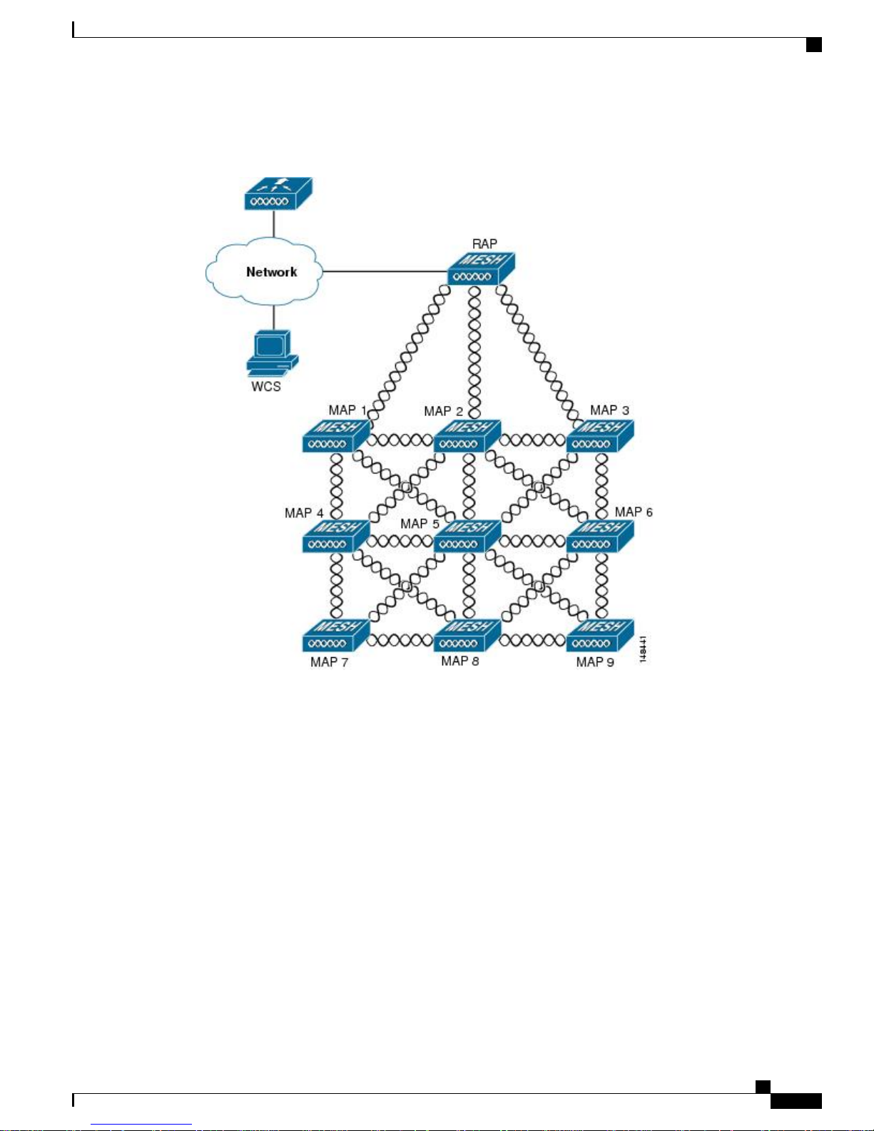
This figure shows the relationship between RAPs and MAPs in a mesh network.
Figure 1: Simple Mesh Network Hierarchy
Network Access
Network Access
Wireless mesh networks can simultaneously carry two different traffic types. They are as follows:
• Wireless LAN client traffic
• MAP Ethernet port traffic
Wireless LAN client traffic terminates on the controller, and the Ethernet traffic terminates on the Ethernet
ports of the mesh access points.
Access to the wireless LAN mesh for mesh access points is managed by the following authentication methods:
• MAC authentication—Mesh access points are added to a database that can be referenced to ensure they
are provided access to a given controller and mesh network.
• External RADIUS Authentication—Mesh access points can be externally authorized using a RADIUS
server such as Cisco ACS (4.1 and later) that supports the client authentication type of Extensible
Authentication Protocol-FAST (EAP-FAST) with certificates.
OL-27593-01 3
Cisco Mesh Access Points, Design and Deployment Guide, Release 7.3
Page 20

Network Segmentation
Network Segmentation
Membership to the wireless LAN mesh network for mesh access points is controlled by the bridge group
names (BGNs). Mesh access points can be placed in similar bridge groups to manage membership or provide
network segmentation.
Cisco Indoor Mesh Access Points
Indoor mesh is available on the following access points:
• 802.11a/b/g
• 1130
• 1240
• 802.11n
Mesh Network Components
Note
• 1040
• 1140
• 1250
• 1260
• 802.11n+CleanAir
• 2600
• 3500e
• 3500i
• 3600
For more information about controller software support for access points, see the Cisco Wireless Solutions
Software Compatibility Matrix at http://www.cisco.com/en/US/docs/wireless/controller/5500/tech_notes/
Wireless_Software_Compatibility_Matrix.html.
Enterprise 11n mesh is an enhancement added to the CUWN feature to work with the 802.11n access points.
Enterprise 11n mesh features are compatible with non-802.11n mesh but adds higher backhaul and client
access speeds. The 802.11n indoor access points are two-radio Wi-Fi infrastructure devices for select indoor
deployments. One radio can be used for local (client) access for the access point and the other radio can be
configured for wireless backhaul. The backhaul is supported only on the 5-GHz radio. Enterprise 11n mesh
supports P2P, P2MP, and mesh types of architectures.
You have a choice of ordering indoor access points directly into the bridge mode, so that these access points
can be used directly as mesh access points. If you have these access points in a local mode (nonmesh), then
you have to connect these access points to the controller and change the AP mode to the bridge mode (mesh).
This scenario can become cumbersome particularly if the volume of the access points being deployed is large
and if the access points are already deployed in the local mode for a traditional nonmesh wireless coverage.
Cisco Mesh Access Points, Design and Deployment Guide, Release 7.3
4 OL-27593-01
Page 21

Mesh Network Components
The Cisco indoor mesh access points are equipped with the following two simultaneously operating radios:
• 2.4-GHz radio used for client access
• 5-GHz radio used for data backhaul
The 5-GHz radio supports the 5.15 GHz, 5.25 GHz, 5.47 GHz, and 5.8 GHz bands.
Cisco Outdoor Mesh Access Points
Cisco outdoor mesh access points comprise of the Cisco Aironet 1500 series access points. The 1500 series
includes 1552 11n outdoor mesh access points, 1522 dual-radio mesh access points, and 1524 multi-radio
mesh access points. There are two models of the 1524, which are the following:
• The public safety model, 1524PS
• The serial backhaul model, 1524SB
Cisco Outdoor Mesh Access Points
Note
In the 6.0 release, the AP1524SB access point was launched in A, C, and N domains.
In the 7.0 release, the AP1524SB access point was launched in the -E, -M, -K, -S, and
-T domains.
Cisco 1500 series mesh access points are the core components of the wireless mesh deployment. AP1500s
are configured by both the controller (GUI and CLI) and Cisco Prime Infrastructure. Communication between
outdoor mesh access points (MAPs and RAPs) is over the 802.11a/n radio backhaul. Client traffic is generally
transmitted over the 802.11b/g/n radio (802.11a/n can also be configured to accept client traffic), and public
safety traffic (AP1524PS only) is transmitted over the 4.9-GHz radio.
The mesh access point can also operate as a relay node for other access points not directly connected to a
wired network. Intelligent wireless routing is provided by the Adaptive Wireless Path Protocol (AWPP). This
Cisco protocol enables each mesh access point to identify its neighbors and intelligently choose the optimal
path to the wired network by calculating the cost of each path in terms9 of the signal strength and the number
of hops required to get to a controller.
AP1500s are manufactured in two different configurations: cable and noncable.
• The cable configuration can be mounted to a cable strand and supports power-over-cable (POC).
• The noncable configuration supports multiple antennas. It can be mounted to a pole or building wall
and supports several power options.
Uplinks support includes Gigabit Ethernet (1000BASE-T) and a small form-factor (SFP) slot that can be
plugged for a fiber or cable modem interface. Both single mode and multimode SFPs up to 1000BASE-BX
are supported. The cable modem can be DOCSIS 2.0 or DOCSIS/EuroDOCSIS 3.0 depending upon the type
of mesh access point.
AP1500s are available in a hazardous location hardware enclosure. When configured, the AP1500 complies
with safety standards for Class I, Division 2, Zone 2 hazardous locations.
OL-27593-01 5
Cisco Mesh Access Points, Design and Deployment Guide, Release 7.3
Page 22

Cisco Outdoor Mesh Access Points
Mesh Network Components
Note
See the Cisco Aironet 1520 Series Lightweight Outdoor Access Point Ordering Guide for power, mounting,
antenna, and regulatory support by model: http://www.cisco.com/en/US/prod/collateral/wireless/ps5679/
ps8368/product_data_sheet0900aecd8066a157.html
The 1520 and 1550 series access points, can operate, apart from the mesh mode, in the following modes:
• Local mode—In this mode, the AP can handle clients on its assigned channel or while monitoring all
channels on the band over a 180-second period. During this time, the AP listens on each channel for 50
milliseconds for rogue client beacons, noise floor measurements, interference, and IDS events. The AP
also scans for CleanAir interference on the channel.
• FlexConnect mode—FlexConnect is a wireless solution for branch office and remote office deployments.
The FlexConnect mode enables you to configure and control access points in a branch or remote office
from the corporate office through a WAN link without having to deploy a controller in each office. The
FlexConnect mode can switch client data traffic locally and perform client authentication locally when
the connection to the controller is lost. When connected to the controller, the FlexConnect mode can
also tunnel traffic back to the controller.
• Monitor mode—In this mode, the AP radios are in the receive state. The AP scans all the channels every
12 seconds for rogue client beacons, noise floor measurements, interference, IDS events, and CleanAir
intruders.
• Rogue Detector mode—In this mode, the AP radio is turned off, and the AP listens only to the wired
traffic. The controller passes the APs that are configured as rogue detectors as well as lists of suspected
rogue clients and AP MAC addresses. The rogue detector listens for ARP packets and can be connected
to all broadcast domains through a trunk link.
• Sniffer mode—In this mode, the AP captures and forwards all packets on a channel to a remote device
that decodes the packets with packet analyzer software such as Wireshark.
Note
You can configure these modes using both the GUI and CLI. For configuration instructions, see the Cisco
Wireless LAN Controller Configuration Guide.
Note
MAPs can only be configured in Bridge mode regardless of their wired or wireless backhaul. If the MAPs
have a wired backhaul, you must change their AP role to RAP before you change the AP Mode.
Cisco Aironet 1552 Mesh Access Point
The Cisco Aironet 1550 Series Outdoor Mesh Access Point is a modularized wireless outdoor 802.11n access
point designed for use in a mesh network. The access point supports point-to-multipoint mesh wireless
connectivity and wireless client access simultaneously. The access point can also operate as a relay node for
other access points that are not directly connected to a wired network. Intelligent wireless routing is provided
by the Adaptive Wireless Path Protocol (AWPP). This enables the access point to identify its neighbors and
intelligently choose the optimal path to the wired network by calculating the cost of each path in terms of
signal strength and the number of hops required to get to a controller.
Cisco Mesh Access Points, Design and Deployment Guide, Release 7.3
6 OL-27593-01
Page 23

Mesh Network Components
The 1550 series access points leverage 802.11n technology with integrated radio and internal/external antennas.
The 1552 outdoor platform consists of Multiple Input Multiple Output (MIMO) WLAN radios. It offers 2x3
MIMO with two spatial streams, Beamforming, and comes with integrated spectrum intelligence (CleanAir).
CleanAir provides full 11n data rates while detecting, locating, classifying, and mitigating radio frequency
(RF) interference to provide the best client experience possible. CleanAir technology on the outdoor 11n
platform mitigates Wi-Fi and non-Wi-Fi interference on 2.4-GHz radios.
The 1550 series access points have two radios—2.4-GHz and 5-GHz MIMO radios. While the 2.4-GHz radios
are used primarily for local access, the 5-GHz radios are used for both local access and wireless backhaul in
mesh mode.
The 2.4-GHz radios cannot be used for backhaul in 1552 APs.Note
The 2-GHz b/g/n radio has the following features:
Cisco Outdoor Mesh Access Points
• Operates in the 2.4-GHz ISM band.
• Supports channels 1-11 in the United States, 1-13 in Europe, and 1-13 in Japan.
• Has two transmitters for 802.11b/g/n operation.
• You can configure the output power for 5 power levels.
• The radio has three receivers that enable maximum-ratio combining (MRC).
The 5-GHz a/n radio has the following feature:
• Operates in the UNII-2 band (5.25 to 5.35 GHz), UNII-2 Extended/ETSI band (5.47 to 5.725 GHz), and
the upper ISM band (5.725 to 5.850 GHz).
• Has two transmitters for 802.11a operation.
• Power settings can change depending on the regulatory domain. You can configure the output power
for 5 power levels in 3 dB steps.
• The radio has three receivers that enable maximum-ratio combining (MRC).
The 1550 series access points have the following features:
• Supports modularity of the 1520 series and allows flexibility in radio configuration
• Fully interoperable with the 1520 series access points
• Can also interoperate with legacy clients and offers enhanced backhaul performance
• Multicast VideoStream and HotSpot 2.0 are supported when the AP is configured in Local mode.
• AP1552 is QoS capable of supporting quality VoWLAN calls.
• Band Select, which notifies a connected client to roam from 2.4 GHz to 5 GHz, is supported.
• DTLS support allows AP1552 to encrypt data in all supported AP modes except Bridge mode.
• You can enable CleanAir on the 5-GHz radio by navigating to Wireless > Radios > 802.11a > Configure
on the controller GUI.
OL-27593-01 7
Cisco Mesh Access Points, Design and Deployment Guide, Release 7.3
Page 24

Cisco Outdoor Mesh Access Points
• If AP1552 is in Bridge mode, CleanAir Advisor becomes operational. CleanAir Advisor generates
CleanAir reports and identifies interference. The event driven RRM is disabled. Therefore, the radio
does not change the transmission power level or channel.
The models can be classified as models with external antennas and models with built-in antennas. The 1552C
model is configured with an integrated DOCSIS/EuroDOCSIS 3.0 cable modem. The DOCSIS 3.0 cable
modem provides 8 DS and 4 US (8x4), 304x108 Mbps. The EuroDOCSIS 3.0 cable modem provides 4 US
and 4 DS (4x4), 152x108 Mbps. While a DOCSIS 2.0 cable modem could provide throughput of up to 40
Mbps only, a DOCSIS 3.0 cable modem can provide a DS throughput of 290 Mbps and a US throughput of
100 Mbps.
The 1552 Access Point is available in these models:
• 1552E, on page 8
• 1552C, on page 9
• 1552I, on page 9
• 1552H, on page 10
• 1552CU, on page 10
Mesh Network Components
• 1552EU, on page 11
For more information about the Cisco 1550 Series Access Points, see http://www.cisco.com/en/US/products/
ps11451/index.html.
1552E
The Cisco Aironet 1552E Outdoor Access Point is the standard model, dual-radio system with dual-band
radios that are compliant with IEEE 802.11a/n (5-GHz) and 802.11b/g/n standards (2.4 GHz). The 1552E has
three external antenna connections for three dual-band antennas. It has Ethernet and fiber Small Form Factor
Pluggable (SFP) backhaul options, along with the option of a battery backup. This model also has a PoE-out
port and can power a video surveillance camera. A highly flexible model, the Cisco Aironet 1552E is well
equipped for municipal and campus deployments, video surveillance applications, mining environments, and
data offload.
The 1552E model has the following features:
• Weighs 17.3 lbs (7.9 kg) excluding external antennas
• Two radios (2.4 GHz and 5 GHz)
• Three external dual-band omnidirectional antennas with 4 dBi in 2.4 GHz and 7 dBi in 5 GHz
• Vertical beamwidth: 29° at 2.4 GHz, 15° at 5 GHz
• Aligned console port
• Higher equivalent isotropically radiated power (EIRP)
• Multiple uplinks with Ethernet and fiber
• An optional Small Form Factor Pluggable (SFP) fiber module that can be ordered with the AP. The AP
can use SFP fiber or copper module.
• 802.3af-compliant PoE-Out option to connect IP devices (such as video cameras)
• AC Powered (100 to 480 VAC)
Cisco Mesh Access Points, Design and Deployment Guide, Release 7.3
8 OL-27593-01
Page 25

Mesh Network Components
1552C
Where service providers have already invested in a broadband cable network, the Cisco next-generation
outdoor wireless mesh can seamlessly extend network connectivity with the Cisco Aironet 1552C access point
by connecting to its integrated cable modem interface. The Cisco Aironet 1552C Outdoor Mesh Access Point
is a dual-radio system with DOCSIS 3.0/EuroDOCSIS 3.0 (8x4 HFC) cable modem for power and backhaul.
It has dual-band radios that are compliant with IEEE 802.11a/n (5 GHz) and 802.11b/g/n standards (2.4 GHz).
The 1552C has an integrated, three- element, dual-band antenna and easily fits within the 30 cm height
restriction for service providers. This model is suitable for 3G data offload applications and public Wi-Fi.
The 1552C model has the following features:
Cisco Outdoor Mesh Access Points
• PoE-In using Power Injector
• Battery backup option (6 AH)
The 1552E model has no cable modem. The 1552E battery cannot be used for 1552H.Note
• AP1552E can be ordered with an Ethernet Passive Optical Network SFP as an add-on. The EPON SFP
provides Gigabit data rates.
The EPON SFP feature must be ordered separately and installed.Note
• Lightweight (14 lbs or 6.4 kg), low-profile AP
• Two radios (2.4 GHz and 5 GHz)
• DOCSIS/EuroDOCSIS 3.0 Cable Modem
• Aligned console port
• It supports cable modem backhaul
• Has an integrated 3-element array antenna with 2 dBi in 2.4 GHz and 4 dBi in 5 GHz
• Input module, power-over-cable supply (40 to 90 VAC)
• Stamped cover with two convenient holes to tighten the seizure screw for stringer connector (RF/Power
Input) and to adjust the fuse pad to attenuate the signal
Note
The 1552C model has no battery backup, no fiber SFP support, no PoE Out, no PoE In
using Power Injector or Ethernet port, and no AC power option.
1552I
The Cisco Aironet 1552I Outdoor Access Point is a low-profile, lighter weight model. The smaller size and
sleeker look helps it blend with the surrounding environment. The smaller power supply also makes it an
energy efficient product. The 1552I does not have PoE-Out or a fiber SFP port.
The 1552I model has the following features:
OL-27593-01 9
Cisco Mesh Access Points, Design and Deployment Guide, Release 7.3
Page 26

Cisco Outdoor Mesh Access Points
• Lightweight (14 lbs or 6.4 kg), low-profile version
• Two radios (2.4 GHz and 5 GHz)
• Aligned console port
• AC powered (100 to 277 VAC)
• Stamped cover with no holes
• Supports street light power TAP
Mesh Network Components
Note
The 1552I model has no battery backup, no fiber SFP support, no cable modem, and no
PoE Out.
1552H
This access point is designed for hazardous environments like oil and gas refineries, chemical plants, mining
pits, and manufacturing factories. The Cisco Aironet 1552H Outdoor Access Point is Class 1, Div 2/Zone 2
hazardous location certified. The features are similar to the 1552E model, with the exception of the battery
backup.
The 1552H model has the following features:
• Weighs 14 lbs (6.4 kg)
• Two radios (2.4 GHz and 5 GHz)
• Hazardous Location (Haz Loc) version.
• Power-over-Ethernet (PoE) input using Power Injector
• Aligned console port
• Three dual-band external omnidirectional antennas
• AC entry module with terminal block
• AC powered (100 to 240 VAC, as per ATEX certification requirement)
• Fiber SFP backhaul option
• 802.3af-compliant PoE Out option to connect IP devices (such as video cameras)
• Battery backup option (special battery for hazardous locations)
For more information about Cisco Aironet 1552 mesh access point hardware and installation instructions, see
http://www.cisco.com/en/US/products/ps11451/prod_installation_guides_list.html
1552CU
The 1552CU model has the following features:
• Two radios (2.4 GHz and 5 GHz)
• Aligned console port
• AC powered (40 to 90 VAC)
Cisco Mesh Access Points, Design and Deployment Guide, Release 7.3
10 OL-27593-01
Page 27

Mesh Network Components
1552EU
The 1552EU model has the following features:
Cisco Outdoor Mesh Access Points
• Stamped cover with no holes
• External high-gain antennas (13 dBi in 2.4 GHz, 14 dBi in 5 GHz)
• Cable modem
• Two radios (2.4 GHz and 5 GHz)
• Aligned console port
• AC powered (90 to 480 VAC)
• PoE 802.3af
• External high-gain antennas (13 dBi in 2.4 GHz, 14 dBi in 5 GHz)
• Battery
• AP1552EU can be ordered with an Ethernet Passive Optical Network SFP as an add-on. The EPON
SFP provides Gigabit data rates.
The EPON SFP feature must be ordered separately and installed.Note
Cisco 1522 Mesh Access Point
The AP1522 mesh access point (part numbers: AIR–LAP1522AG–X–K9, AIR–LAP1522HZ–X–K9,
AIR–LAP1522PC–X–K9) includes two radios: a 2.4-GHz and a 4.9- to 5.8-GHz radio. The 2.4-GHz (802.11b/g)
radio is for client access and the 5-GHz (802.11a) radio is used as the backhaul. With the 7.0.116.0 release
and later releases, 2.4 GHz is available for backhaul. This feature is applicable only to AP1522.
The 5-GHz radio is a 802.11a radio that covers the 4.9- to 5.8-GHz frequency band and is used as a backhaul.
It can also be used for client access if the universal client access feature is enabled.
Note
AP1522s with serial numbers prior to FTX1150XXXX do not support 5- and 10-MHz channels on the
4.9-GHz radio; however, a 20-MHz channel is supported.
Note
Those AP1522s with serial numbers after FTX1150XXXX support 5-, 10-, and 20-MHz channels.
Cisco 1524PS Mesh Access Point
The AP1524PS mesh access point (part number: AIR–LAP1524PS–X–K9) includes three radios: a 2.4-GHz,
a 5.8-GHz, and a 4.9-GHz radio. The 2.4-GHz radio is for client access (nonpublic safety traffic) and the
4.9-GHz radio is for public safety client access traffic only. The 5.8-GHz radio can be used as the backhaul
for both public safety and nonpublic safety traffic.
OL-27593-01 11
Cisco Mesh Access Points, Design and Deployment Guide, Release 7.3
Page 28
Cisco Outdoor Mesh Access Points
The 4.9-GHz and 5.8-GHz radios are 802.11a subband radios that support a subset of specific 802.11a channels
and include a subband specific filter designed to lessen interference from other 11a subband radios within the
same mesh access point.
The 4.9-GHz subband radio on the AP1524 supports public safety channels within the 5-MHz (channels 1 to
10), 10-MHz (channels 11 to 19), and 20-MHz (channels 20 to 26) bandwidths.
• The data rates supported within the 5-MHz bandwidth are 1.5, 2.25, 3, 4.5, 6, 9, 12, and 13.5 Mbps. The
default rate is 6 Mbps.
• The data rates supported within the 10-MHz bandwidth are 3, 4.5, 6, 9, 12, 18, 24, and 27 Mbps. The
default rate is 12 Mbps.
Cisco 1524SB Mesh Access Point
The AP1524SB mesh access point (part number: AIR–LAP1524SB–X–K9) includes three radios: one 2.4-GHz
radio and two 5-GHz radios.
The 2.4-GHz radio is for client access (nonpublic safety traffic). The two 5-GHz radios serve as serial backhauls:
one uplink and one downlink. The AP1524SB is suitable for linear deployments.
Mesh Network Components
Note
In the 6.0 release, the 5-GHz radios in the –A domain could be operated only in the 5.8-GHz band with
5 channels. In the 7.0 release, these radios cover the whole 5-GHz band.
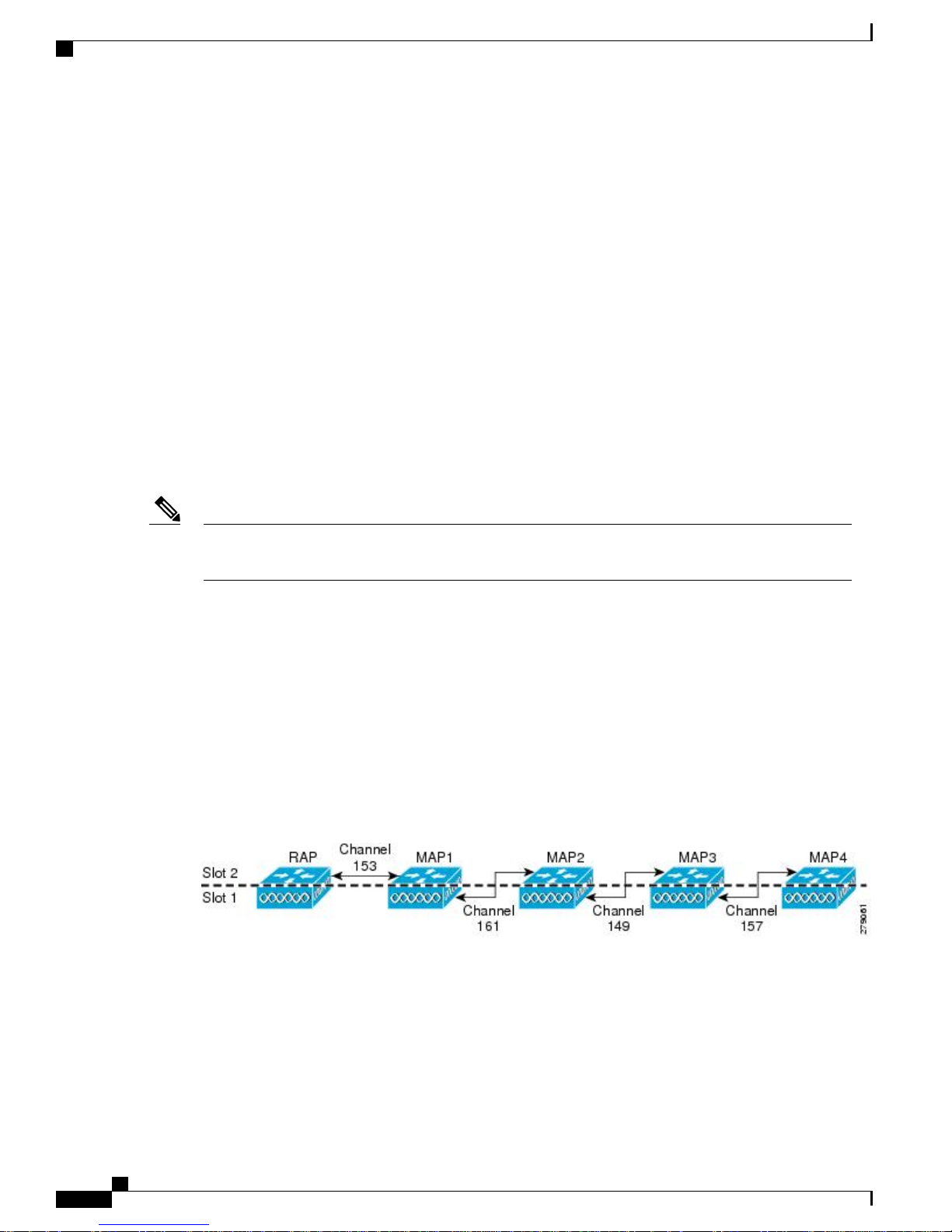
Each 5-GHz radio backhaul is configured with a different backhaul channel. There is no need to use the same
shared wireless medium between the north-bound and south-bound traffic in a mesh tree-based network.
On the RAP, the radio in slot 2 is used to extend the backhaul in the downlink direction; the radio in slot 1 is
used only for client access and not mesh.
On the MAP, the radio in slot 2 is used for the backhaul in the uplink direction; the radio in slot 1 is used for
the backhaul in the downlink direction.
You only need to configure the RAP downlink (slot 2) channel. The MAPs automatically select their channels
from the channel subset. The available channels for the 5.8-GHz band are 149, 153, 157, 161, and 165.
This figure shows an example of channel selection when the RAP downlink channel is 153.
Figure 2: Channel Selection Example
Fall Back Mode
Slot 1 in a 5-GHz radio in a MAP can act as an uplink radio for the backhaul in any one of the following
scenarios:
• Slot 2 radio fails.
• Antenna for slot 2 radio goes bad.
Cisco Mesh Access Points, Design and Deployment Guide, Release 7.3
12 OL-27593-01
Page 29
Mesh Network Components
When a slot 1 radio takes over a slot 2 radio, it is called Fall Back Mode. The slot 2 radio is made inactive on
a noninterfering channel. The hardware is reduced to AP1522 (two radios). The slot 1 radio (omni antenna)
is extended to the uplink. A period of 15 minutes is set on a timer to attempt a rescan to find a parent on the
slot 2 radio again. The timer is similar to the default BGN timer.
This figure shows an example of the Fall Back Mode.
Figure 3: Fall Back Mode
Cisco Outdoor Mesh Access Points
• Slot 2 radio is unable to find the uplink because of a bad RF design.
• Interference and long-term fades disturb the uplink to the extent that the slot 2 radio loses its uplink
connection.
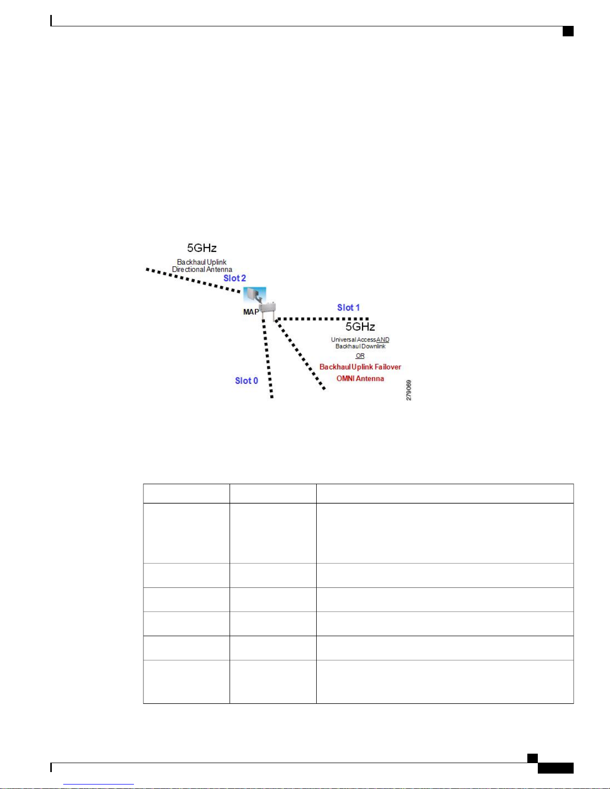
The antenna ports are labeled on the AP1524SB and are connected internally to the radios in each slot.
The AP1524SB has six ports with three radio slots (0, 1, 2) as described in Table 2: AP1524SB Antenna
Ports, on page 13.
Table 2: AP1524SB Antenna Ports
DescriptionRadio SlotAntenna Port
11
5 GHz–Used for backhaul and universal access. Universal access
is configured only on slot 1.
Note
Omni antenna is
required.
2 GHz–Used for client access.02
2 GHz–Used for client access.03
2 GHz–Used for client access.04
Not connected.—5
26
5 GHz–Used for backhaul.
Note
Directional antenna is
required.
OL-27593-01 13
Cisco Mesh Access Points, Design and Deployment Guide, Release 7.3
Page 30

Cisco Outdoor Mesh Access Points
Mesh Network Components
Note
Ethernet Ports
AP1500s support four Gigabit Ethernet interfaces.
You can query the status of these four interfaces in the controller CLI and Cisco Prime Infrastructure.
In the controller CLI, the show mesh env summary command is used to display the status of the ports.
Depending on the product model, the AP1524SB could have either 5-GHz radios or 5.8-GHz subband
radios installed in slot 1 and slot 2. Regardless of the radios installed, the AP1524SB running controller
software release 6.0 is restricted to the UNII-3 channels (149, 153, 157, 161, and 165) in slot 1 and slot
2.
• Port 0 (g0) is a Power over Ethernet (PoE) input port–PoE (in)
• Port 1 (g1) is a PoE output port–PoE (out)
• Port 2 (g2) is a cable connection
• Port 3 (g3) is a fiber connection
• The Up or Down (Dn) status of the four ports is reported in the following format:
◦ port0(PoE-in):port1(PoE-out):port2(cable):port3(fiber)
•
For example, rap1522.a380 in the display below shows a port status of UpDnDnDn. This indicates the
following:
◦ PoE-in port 0 (g0) is Up, PoE-out port 1 (g1) is Down (Dn), Cable port 2 (g2) is Down (Dn), and
Fiber port 3 (g3) is Down (Dn).
(controller)> show mesh env summary
AP Name Temperature(C/F) Heater Ethernet Battery
-------- --------------- -------- ------- ------rap1242.c9ef N/A N/A UP N/A
rap1522.a380 29/84 OFF UpDnDnDn N/A
rap1522.4da8 31/87 OFF UpDnDnDn N/A
Multiple Power Options
For the 1550 Series
Power options include the following:
• Power over Ethernet (PoE)-In
◦ 56 VDC using a Power Injector (1552E and 1552H)
◦ PoE-In is not 802.3af and does not work with PoE 802.3af-capable Ethernet switch
Cisco Mesh Access Points, Design and Deployment Guide, Release 7.3
14 OL-27593-01
Page 31

Mesh Network Components
Cisco Outdoor Mesh Access Points
• AC Power
◦ 100 to 480 VAC (47-63 Hz)—Connecting AC or Streetlight Power (1552E)
◦ 100 to 240 VAC—Connecting AC or Streetlight Power (1552H)
• External Supply
◦ 12 VDC—Connecting DC Power Cable (All Models)
• Internal Battery Backup (1552E and 1552H)
• Power over Cable (PoC)
◦ 40 to 90VAC—Connecting Cable PoC (1552C)
• PoE-Out 802.3af compliant to connect IP devices such as Video Cameras (1552E and 1552H)
◦ (PoE-Out) is not available when using Power Injector (PoE-In) as the power source
• 802.3af compliant PoE-Out to connect IP devices such as video cameras (1552E and 1552H)
This port also performs Auto-MDIX, which enables to connect crossover or straightthrough cables.
The 1550 series access points can be connected to more than one power source. The access points detect the
available power sources and switch to the preferred power source using the following default prioritization:
• AC power or PoC power
• External 12-VDC power
• Power injector PoE power
• Internal battery power
Table 3: Power Options in 1552 Models, on page 15 lists the power options available for the 1552 access
point models.
Table 3: Power Options in 1552 Models
1552I1552C1552H1552EPower Option
AC
100 to 480 VAC
80W
Not Applicable100 to 240 VAC
80W
Not ApplicableNot ApplicablePower over Cable
100 to 277 VAC
50W
Not Applicable40-90 V (quasi-
square wave)
45W
Not ApplicableNot Applicable56V +/- 10%56V +/- 10%PoE (using Power
Injector)
VDC)
OL-27593-01 15
11.4 – 15V11.4 – 12.6V11.4 – 15V11.4 – 15VDC (nominal 12
Not ApplicableNot Applicable35W-hr80W-hrBattery Backup
Cisco Mesh Access Points, Design and Deployment Guide, Release 7.3
Page 32

Cisco Outdoor Mesh Access Points
For the 1520 Series
Power options include the following:
• 100 to 480 VAC streetlight power
• 12 VDC
• Power-over-cable power supply (40 to 90 VAC)
• PoE using a separate power injection system (48 VDC)
◦ For more information about the power injection, its specifications, and installation, see http://
• Internal battery backup power
• 802.3af-compliant PoE-Out to connect IP devices (such as video cameras)
This port also performs Auto-MDIX, which allows to connect crossover or straightthrough cables.
Mesh Network Components
www.cisco.com/en/US/docs/wireless/access_point/1520/power/guide/1520pwrinj.html
Battery Backup Module (Optional)
Battery backup six-ampere hour module is available for the following:
• AIR-1520-BATT-6AH for AP1520s
• AIR-1550-BATT-6AH for only the AIR-CAP-1552E-x-K9 model
The integrated battery can be used for temporary backup power during external power interruptions.
The battery run time for AP1520s is as follows:
• 3-hour access point operation with up to 3 radios at 77oF (25oC) with PoE output port off
• 2-hour access point operation with up to 3 radios at 77oF (25oC) with PoE output port on
The battery run time for AP1550s is as follows:
• 2-hour access point operation using two radios at 77oF (25oC) with PoE output port off
• 1.5-hour access point operation using two radios at 77oF (25oC) with PoE output port on
The battery pack is not supported on the access point cable configuration.
Note
For a complete listing of optional hardware components for AP1520s such as mounting brackets, power
injectors, and power tap adapters, see http://www.cisco.com/en/US/prod/collateral/wireless/ps5679/ps8368/
product_data_sheet0900aecd8066a157.html
Cisco Mesh Access Points, Design and Deployment Guide, Release 7.3
16 OL-27593-01
Page 33

Mesh Network Components
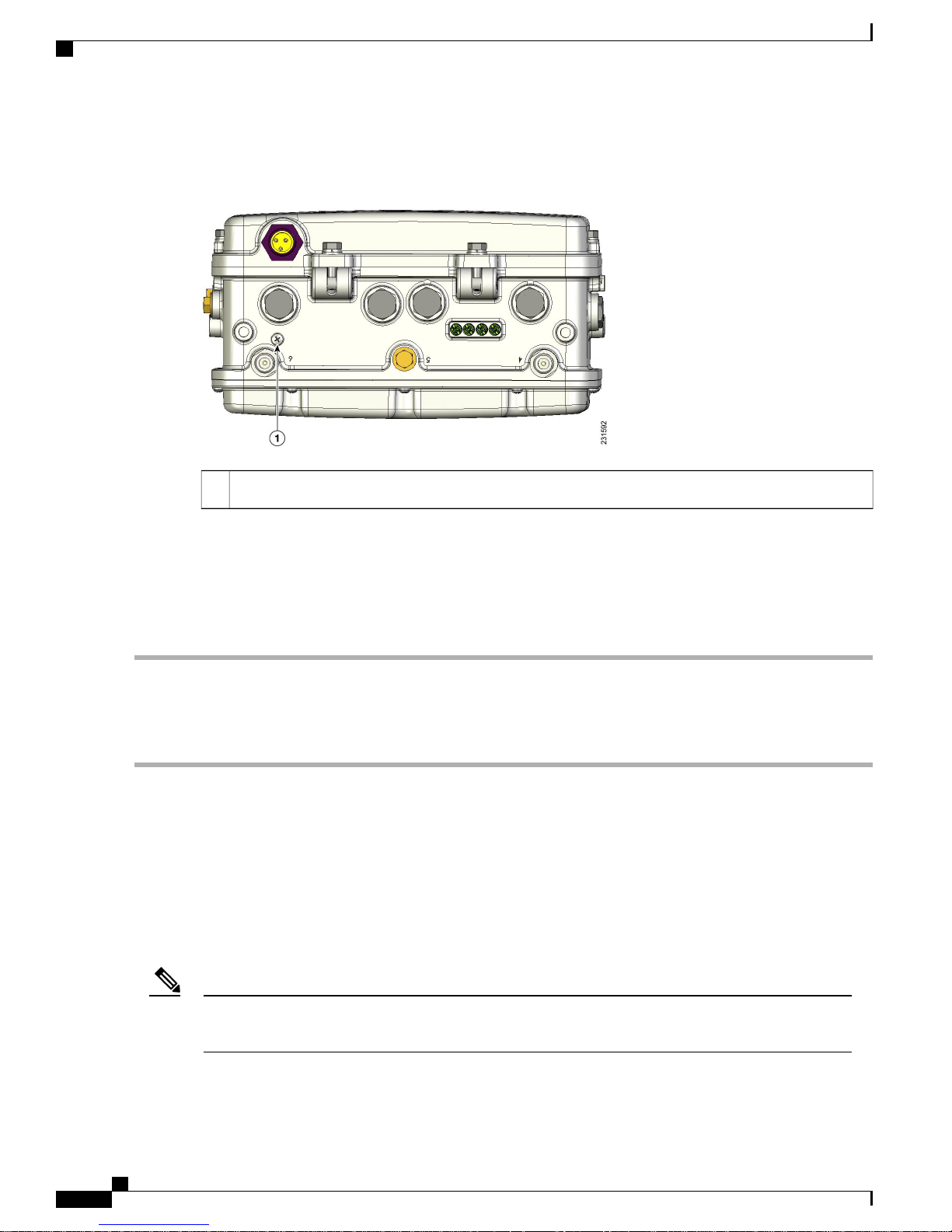
Reset Button
A 1500 series access point has a reset button located on the bottom of the unit. The reset button is recessed
in a small hole that is sealed with a screw and a rubber gasket. The reset button can be used to perform the
following functions:
Cisco Outdoor Mesh Access Points
• Reset the access point—Press the reset button for less than 10 seconds, and the LEDs turn off during
the reset and then reactivate when the reset is complete.
• Disable battery backup power—Press the reset button for more than 10 seconds, and the LEDs turn off,
then on, and then stay off.
◦ You can also disable the battery remotely by entering the following command:
config mesh battery-state disable AP_name
• Switch off LEDs—Press the reset button for more than 10 seconds, and the LEDs turn off, then on, and
then stay off.
Figure 4: Reset Button Location - Models AIR-CAP1552E-x-K9 and AIR-CAP1552H-x-K9
Reset button1
Figure 5: Reset Button Location - Models AIR-CAP1552C-x-K9 and AIR-CAP1552I-x-K9
Reset button1
OL-27593-01 17
Cisco Mesh Access Points, Design and Deployment Guide, Release 7.3
Page 34
Cisco Outdoor Mesh Access Points
Figure 6: Reset Button Location for 1520 Series
Mesh Network Components
Resetting Access Point
To reset the access point, follow these steps:
Step 1
Step 2
Use a Phillips screwdriver to remove the reset button screw. Ensure that you do not lose the screw.
Use a straightened paperclip, and push the reset button for less than 10 seconds. This step causes the access point to
reboot (power cycle), all LEDs turn off for approximately 5 seconds, and then the LEDs reactivate.
Step 3
Replace the reset button screw, and use a Phillips screwdriver to tighten to 22 to 24 in. lbs (2.49 to 2.71 nm).
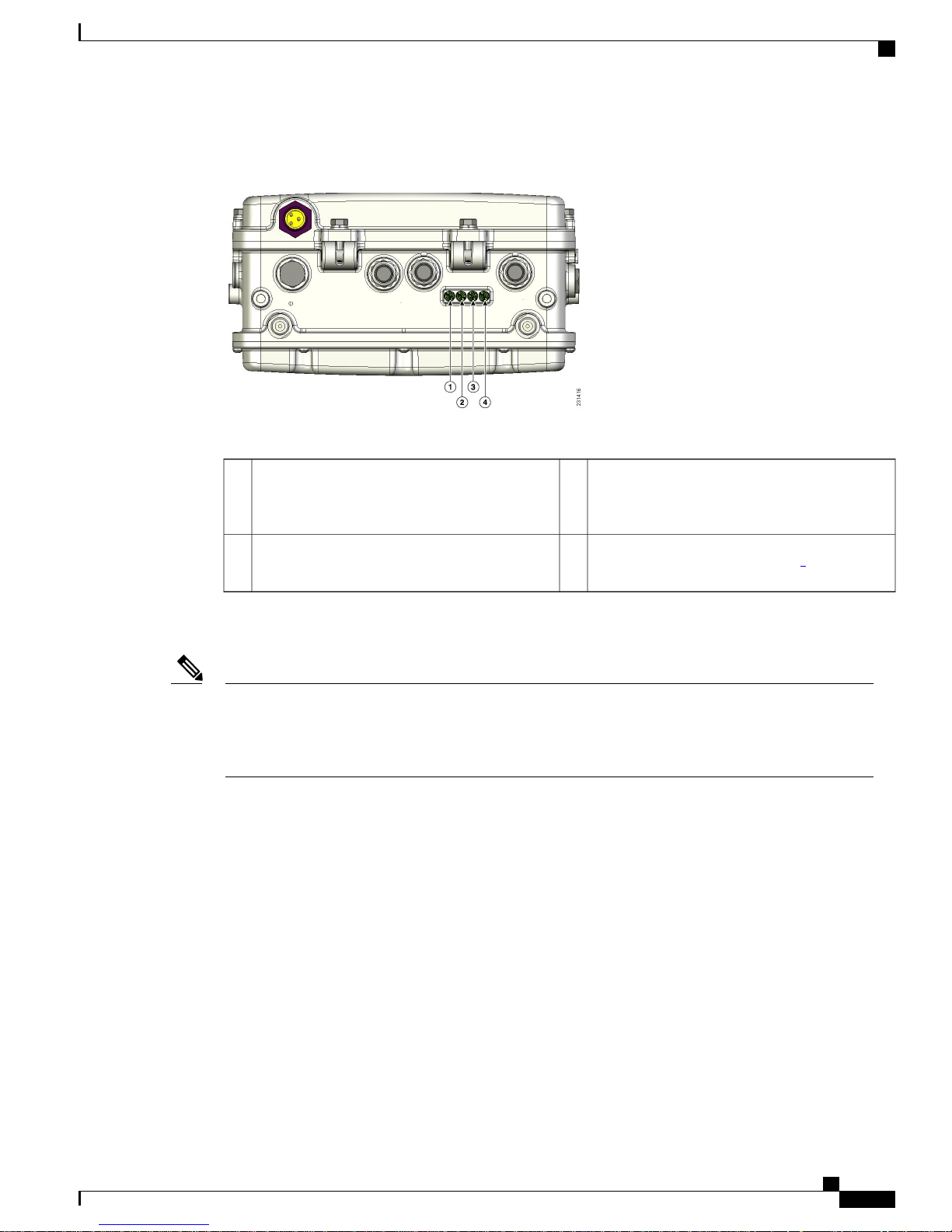
Monitoring the LED Status
The four-status LEDs on AP1500s are useful during the installation process to verify connectivity, radio status,
access point status, and software status. However, once the access point is up and running and no further
diagnosis is required, we recommend that you turn off the LEDs to discourage vandalism.
If your access point is not working as expected, see the LEDs at the bottom of the unit. You can use them to
quickly assess the status of the unit.
Reset button location1
Note
LEDs are enabled or disabled using the config ap led-state {enable | disable} {cisco_ap_name | all}
command.
There are four LED status indicators on AP1500s.
Cisco Mesh Access Points, Design and Deployment Guide, Release 7.3
18 OL-27593-01
Page 35
Mesh Network Components
This figure shows the location of the AP1500 LEDs.
Figure 7: Access Point LEDs at the Bottom of the Unit
The table below describes each LED and its status.
Cisco Outdoor Mesh Access Points
RF-1 LED—Status of the radio in slot 0
3Status LED—Access point and software status1
(2.4-GHz) and slot 2 (5.8-GHz for 1524SB and
4.9-GHz for 1524PS)).
1
Slot 3 is disabled
Note
RF-2 LED—Status of the radio in slot 1
4Uplink LED—Ethernet, cable, or fiber status2
(5.8-GHz) and the radio in slot 3.
1
The RF-1 and RF-2 LEDs monitor two radios simultaneously but do not identify the affected radio. For
example, if the RF-1 LED displays a steady red LED, one or both of the radios in slots 0 and 2 have
experienced a firmware failure. To identify the failing radio, you must use other means, such as the access
point CLI or controller GUI to investigate and isolate the failure.
Table 4: Access Point LED Signals , on page 20 lists the access point LED signals.
OL-27593-01 19
Cisco Mesh Access Points, Design and Deployment Guide, Release 7.3
Page 36

Cisco Outdoor Mesh Access Points
Table 4: Access Point LED Signals
Mesh Network Components
LED
2 3
Blinking green
Red
OffUplink
Green
MeaningColor
Access is point is not powered on.OffStatus
Access point is operational.Green
Download or upgrade of Cisco IOS image file is in
progress.
Mesh neighbor access point discovery is in progress.Amber
Mesh authentication is in progress.Blinking amber
CAPWAP discovery is in progress.Blinking red/green/amber
Firmware failure. Contact your support organization for
assistance.
No physical connector is present. The uplink port is not
operational.
Uplink network is operational (cable, fiber optic, or
Ethernet).
Slot 0
2.4-GHz radio
Slot 2
802.11a radio
Slot 1
802.11a radio
Slot 3
Red
Red
Red
Radio is turned off.OffRF-1
Radio is operational.Green
Firmware failure. Contact your support organization for
assistance.
Radio is turned off.OffRF-1
Radio is operational.Green
Firmware failure. Contact your support organization for
assistance.
Radio is turned off.OffRF-2
Radio is operational.Green
Firmware failure. Contact your support organization for
assistance.
—Disabled in this release.RF-2
Cisco Mesh Access Points, Design and Deployment Guide, Release 7.3
20 OL-27593-01
Page 37

Mesh Network Components
Cisco Outdoor Mesh Access Points
2
If all LEDs are off, the access point has no power.
3
When the access point power supply is initially turned on, all LEDs are amber.
Serial Backhaul Access Point Guidelines for the Rest of the World (ROW)
In the 7.0 release, new 1524 SKUs are released, with both 802.11a radio units supporting the entire 5-GHz
band from 4.9 GHz to 5.8 GHz. This release also opens the 5-GHz band for the -A domain as well on the
existing hardware. The radios can also operate in UNII-2 (5.25 to 5.35 GHz), UNII-2 plus (5.47 to 5.725
GHz), and the upper ISM (5.725 to 5.850 GHz) bands.
The public safety band (4.94 to 4.99 GHz) is not supported for backhaul and for client access.
For information about the channels and maximum power levels of the AP1500 supported within the world's
regulatory domains, see the Channels and Maximum Power Settings for Cisco Aironet Lightweight Access
Points manual at:
• AP1520: http://www.cisco.com/en/US/docs/wireless/access_point/channels/lwapp/reference/guide/1520_
chp.html
• AP1550: http://www.cisco.com/en/US/docs/wireless/access_point/channels/lwapp/reference/guide/
1550pwr_chn.pdf
Table 5: Channels Supported Per Regulatory Domain, on page 21 provides a complete overview of channels
supported in each domain. In addition to 5 channels in the upper ISM band, there are 4 channels in the UNII-2
band and 11 channels in the UNII-2 Plus band. For outdoor APs, there are 5 channels in the upper ISM band,
3 channels in the UNII-2 band, and 8 channels in the UNII-2 Plus band.
Table 5: Channels Supported Per Regulatory Domain
Channel ID
(MHz)
Regulatory DomainsFrequency
-T-S-P-N-M-K-E-C-A
4940-5100 MHz
Yes4920184
Yes4949188
Yes496022/192
Yes498026/196
Yes50408
Yes506012
5250-5350 MHz
526052
OL-27593-01 21
DFSDFS528056
Cisco Mesh Access Points, Design and Deployment Guide, Release 7.3
Page 38

Cisco Outdoor Mesh Access Points
Mesh Network Components
Channel ID
(MHz)
5470-5725 MHz
Regulatory DomainsFrequency
-T-S-P-N-M-K-E-C-A
DFSDFS530060
DFSDFS532064
DFSDFSDFSDFSDFS5500100
DFSDFSDFSDFSDFS5520104
DFSDFSDFSDFSDFS5540108
DFSDFSDFSDFSDFS5560112
DFSDFSDFSDFSDFS5580116
DFSDFS5580120
DFSDFS5620124
DFS5640128
5725-5850 MHz
Note
Channels marked Yes/DFS are channels supported in that domain. Channels marked DFS are
additional DFS-enabled channels and require checks for radar detection. This table is for up to 8
dBi antennas. For higher gain antennas, see http://www.cisco.com/en/US/docs/wireless/access_point/
channels/lwapp/reference/guide/1520_chp.html. For more information about AP1550 series RF Tx
power levels, see http://www.cisco.com/en/US/docs/wireless/access_point/channels/lwapp/reference/
guide/1550pwr_chn.pdf.
DFSDFSDFSDFS5660132
DFSDFSDFSDFS5680136
DFSDFSDFSDFS5700140
YesYesYesDFSYesYes5745149
YesYesYesDFSYesYes5765153
YesYesYesDFSYesYes5785157
YesYesYesDFSYesYes5805161
YesYesYesYesYes5825165
Cisco Mesh Access Points, Design and Deployment Guide, Release 7.3
22 OL-27593-01
Page 39

Mesh Network Components
With the expansion of the channel set, DFS-enabled channels are also supported. Radar detection and automatic
channel reassignment in case of radar detection on RAP/MAPs are also supported. When there is a channel
change, it is also propagated to the corresponding parent/child access point (if applicable) so that the channel
change is synchronized between the parent and child so that there is no link downtime. For example, if radar
is detected on the uplink radio of a child access point, the parent is informed so that it can change the channel
of the downlink radio. The parent in turn informs the child about the channel change, so that the child access
point can set the new channel on its uplink radio as well and does not have to scan again to rejoin the parent
on the new channel.
For countries in the Middle East such as Saudi Arabia and Kuwait, a new regulatory domain for outdoor APs,
the -M domain, has been mandated. With this release, outdoor APs will now support this new -M domain.
Earlier, these countries were part of the -E domain, which supported a channel set of 100 to 140. However,
in the -M domain, channels 149 to 161 are also supported with the 100 to 140 band. Also, in the -M domain,
channels 149 to 161 are DFS enabled, unlike other domains such as -A, -C, -N, and so on, where these channels
are non-DFS. Radar detection is also enabled on these channels. Because the countries that are now part of
the -M domain (that is, Saudi Arabia and Kuwait) were earlier part of the -E domain, both the -E domain and
the -M domain APs are supported, when any of these countries is configured on the controller, which ensures
backward compatibility with the existing -E domain APs in these countries. However, you will have to ensure
that only a valid set of channels (the channels common to both the -E and the -M domains) is selected as part
of the 802.11a DCA list, and that the backhaul channel deselection feature is enabled to ensure correct operation
of the -E domain APs, as these APs can support 100 to 140 channels and not the extended list of 149 to 161
channels available in the -M domain.
Cisco Outdoor Mesh Access Points
Discontinuation of the 116 and 132 Channels from the UNII-2 Extended Band
With the 7.0 release, in AP1522 and AP1524SB platforms, in addition to the 5 channels in the upper ISM
band, there are 3 channels in the UNII-2 band and 8 channels in the UNII-2 Extended band. There are 11
channels in the UNII-2 Extended band, but only 8 are applicable in the outdoors due to stringent dynamic
frequency selection (DFS) conditions for Canada because Canada requires a channel availability check every
10 minutes compared to every 60 seconds in the USA. The 120 (5600 MHz), 124 (5620 MHz), and 128 (5640
MHz) channels have had to be dropped.
The Federal Communications Commission (FCC) has issued a guideline to protect Terminal Doppler Weather
Radar (TDWR) systems operating in the 5600- to 5650-MHz band from interference. Also, the UNII-2 Wi-Fi
operating channels are interfering with the TDWR band. Therefore, with the 7.0.116.0 release, the 116 and
132 channels are dropped in addition to the 120, 124, and 128 channels. The guidelines also require that you
avoid operation in the TDWR band and operate at least 30 MHz away from the TDWR operation frequencies
when devices are installed within 35 km (about 21 miles) or the line-of-sight of the TDWR sites.
Note
Note
Your outdoor installation should be registered in the outdoor database. No fee is required to register your
company. The TDWR location sites can be found on the Internet.
The FCC, the National Telecommunications and Information Administration (NTIA), and the Federal
Aviation Administration (FAA) are continuing to investigate and eliminate cases of interference to TDWRs.
For more information about FCC guidelines for outdoor installations, see http://www.cisco.com/en/US/
prod/collateral/routers/ps272/data_sheet_c78-647116_ps11451_Products_Data_Sheet.html.
OL-27593-01 23
Cisco Mesh Access Points, Design and Deployment Guide, Release 7.3
Page 40

Cisco Outdoor Mesh Access Points
Frequency Bands
Both the 2.4-GHz and 5-GHz frequency bands are supported on the indoor and outdoor access points.
Additionally, the 4.9-GHz public safety band is supported on AP1524PS.
Figure 8: Frequency Bands Supported By 802.11a Radios on AP1520s
Mesh Network Components
Note
The 5-GHz band is a conglomerate of three bands in the USA: 5.150 to 5.250 (UNII-1), 5.250 to 5.350
(UNII-2), 5.470 to 5.725 (UNII-2 Extended), and 5.725 to 5.850 (ISM). UNII-1 and the UNII-2 bands are
contiguous and are treated by 802.11a as being a continuous swath of spectrum 200-MHz wide, more than
twice the size of the 2.4-GHz band (see Table 6: Frequency Band , on page 24).
The 4.9 GHz is a public safety channel within the 5-MHz (channels 1 to 10), 10-MHz (channels 11 to 19),
and 20-MHz (channels 20 to 26) bandwidths.
The –D domain, which is the country domain for India, supports the following:
• 20-MHz channels—169 (5.845 GHz) and 173 (5.865 GHz)
• 40-MHz channels—The channel pair 169/173 (5.855 GHz)
The frequency depends on the regulatory domain in which the access point is installed. For additional
information, see the Channels and Power Levels document at http://www.cisco.com/en/US/docs/wireless/
access_point/channels/lwapp/reference/guide/lw_chp2.html.
Table 6: Frequency Band
Model SupportDescriptionFrequency Band Terms
UNII-1
4
Regulations for UNII devices operating in the
5.15- to 5.25-GHz frequency band. Indoor
1130, 1240, and all 11n
Indoor APs
operation only,
Cisco Mesh Access Points, Design and Deployment Guide, Release 7.3
24 OL-27593-01
Page 41

Mesh Network Components
Cisco Outdoor Mesh Access Points
Model SupportDescriptionFrequency Band Terms
UNII-2
UNII-2 Extended
5
ISM
4
UNII refers to the Unlicensed National Information Infrastructure.
5
SM refers to Industrial Science and Mechanical.
Note
The 1552 access points support only the ISM band in the -A domain. The 1552 access points support the
UNII-2 and UNII-2 Extended bands. The DFS algorithms work as expected. The DFS algorithms can be
implemented in the ETSI and other domains, but not in the -A domain. The product certification is pending
the FCC approval and it might take up to 4 months to get the product certified. After the product is certified,
Cisco will provide new software that will allow the UNII-2 and UNII-2 Extended bands to be used for
the 1552 access points in the -A domain.
Regulations for UNII devices operating in the
5.25- to 5.35-GHz frequency band. DFS and
TPC are mandatory in this band.
Regulations for UNII-2 devices operating in
the 5.470 to 5.725 frequency band.
Regulations for UNII devices operating in the
5.725 to 5.850 GHz frequency band.
1130, 1240, all 11n indoor
APs, 1522, 1524SB, and
1552 (except -A domain)
1130, 1240, all 11n indoor
APs, 1522, 1524SB, 1552
1130, 1240, all 11n indoor
APs, 1522, 1524
(AP1524PS and
AP1524SB), 1552
For regulatory information, see http://www.cisco.com/en/US/prod/collateral/wireless/ps5679/ps5861/product_
data_sheet0900aecd80537b6a.html.
Dynamic Frequency Selection
Previously, devices employing radar operated in frequency subbands without other competing services.
However, controlling regulatory bodies are attempting to open and share these bands with new services like
wireless mesh LANs (IEEE 802.11).
To protect existing radar services, the regulatory bodies require that devices wishing to share the newly opened
frequency subband behave in accordance with the Dynamic Frequency Selection (DFS) protocol. DFS dictates
that to be compliant, a radio device must be capable of detecting the presence of radar signals. When a radio
detects a radar signal, it is required to stop transmitting to for at least 30 minutes to protect that service. The
radio then selects a different channel to transmit on but only after monitoring it. If no radar is detected on the
projected channel for at least one minute, then the new radio service device may begin transmissions on that
channel.
The process for a radio to detect and identify a radar signal is a complicated task that sometimes leads to
incorrect detects. Incorrect radar detections can occur due to a large number of factors, including due to
uncertainties of the RF environment and the ability of the access point to reliably detect actual on-channel
radar.
The 802.11h standard addresses DFS and Transmit Power Control (TPC) as it relates to the 5-GHz band. Use
DFS to avoid interference with radar and TPC to avoid interference with satellite feeder links.
OL-27593-01 25
Cisco Mesh Access Points, Design and Deployment Guide, Release 7.3
Page 42
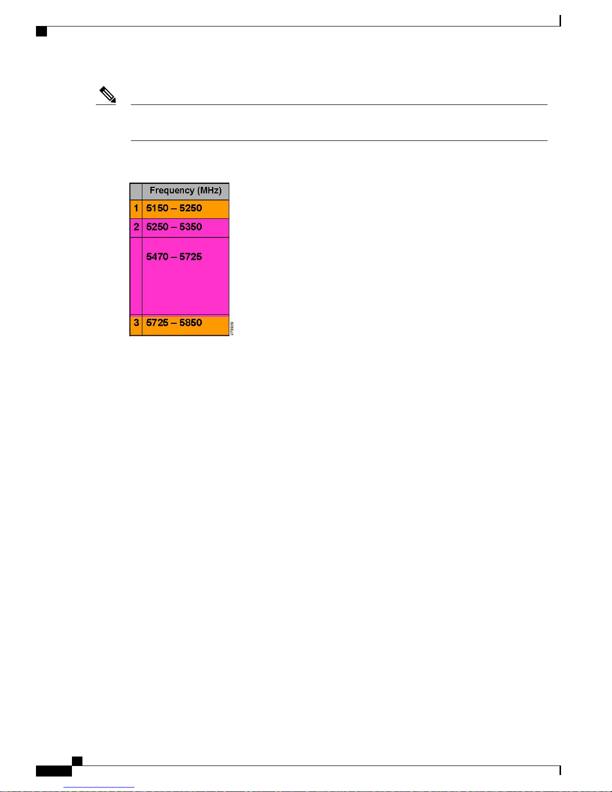
Cisco Outdoor Mesh Access Points
Mesh Network Components
Note
Antennas
DFS is mandatory in the USA for 5250 to 5350 and 5470 to 5725 frequency bands. DFS and TPC are
mandatory for these same bands in Europe.
Figure 9: DFS and TPC Band Requirements
Overview
Antenna choice is a vital component of any wireless network deployment. There are two broad types of
antennas:
• Directional
• Omnidirectional
Each type of antenna has a specific use and is most beneficial in specific types of deployments. Because
antennas distribute RF signal in large lobed coverage areas determined by antenna design, successful coverage
is heavily reliant on antenna choice.
An antenna gives a mesh access point three fundamental properties: gain, directivity, and polarization:
• Gain—A measure of the increase in power. Gain is the amount of increase in energy that an antenna
adds to an RF signal.
• Directivity—The shape of the transmission pattern. If the gain of the antenna increases, the coverage
area decreases. The coverage area or radiation pattern is measured in degrees. These angles are measured
in degrees and are called beamwidths.
Cisco Mesh Access Points, Design and Deployment Guide, Release 7.3
26 OL-27593-01
Page 43

Mesh Network Components
Cisco Outdoor Mesh Access Points
Note
Beamwidth is defined as a measure of the ability of an antenna to focus radio signal
energy toward a particular direction in space. Beamwidth is usually expressed in degrees
HB ?(Horizontal Beamwidth); usually, the most important one is expressed in a VB
(Vertical Beamwidth) (up and down) radiation pattern. When viewing an antenna plot
or pattern, the angle is usually measured at half-power (3 dB) points of the main lobe
when referenced to the peak effective radiated power of the main lobe.
Note
An 8-dBi antenna transmits with a horizontal beamwidth of 360 degrees, causing the
radio waves to disperse power in all directions. Therefore, radio waves from an 8-dBi
antenna do not go nearly as far as those radio waves sent from a 17-dBi patch antenna
(or a third-party dish) that has a more narrow beamwidth (less than 360 degrees).
• Polarization—The orientation of the electric field of the electromagnetic wave through space. Antennas
can be polarized either horizontally or vertically, though other kinds of polarization are available. Both
antennas in a link must have the same polarization to avoid an additional unwanted loss of signal. To
improve the performance, an antenna can sometimes be rotated to alter polarization, which reduces
interference. A vertical polarization is preferable for sending RF waves down concrete canyons, and
horizontal polarization is generally more preferable for wide area distribution. Polarization can also be
harnessed to optimize for RF bleed-over when reducing RF energy to adjacent structures is important.
Most omnidirectional antennas ship with vertical polarization as their default.
Antenna Options
A wide variety of antennas are available to provide flexibility when you deploy the mesh access points over
various terrains. 5 GHz is used as a backhaul and 2.4 GHz is used for client access.
Table 7: External 2.4- and 5-GHz Antennas, on page 27 lists the supported external 2.4- and 5-GHz antennas
for AP1500s.
Table 7: External 2.4- and 5-GHz Antennas
AIR-ANT2450V-N
AIR-ANT5180V-N
OL-27593-01 27
Gain (dBi)ModelPart Number
6
52.4-GHz compact omnidirectional
5.52.4-GHz compact omnidirectionalAIR-ANT-2455V-N
8.02.4-GHz omnidirectionalAIR-ANT2480V-N
7
8.05-GHz compact omnidirectional
8
7.04.9-GHz compact omnidirectional
4.05-GHz right-angle omnidirectionalAIR-ANT5140V-N
9.55-GHz sectorAIR-ANT58G10SSA-N
Cisco Mesh Access Points, Design and Deployment Guide, Release 7.3
Page 44

Cisco Outdoor Mesh Access Points
Mesh Network Components
Gain (dBi)ModelPart Number
14.04.9- to 5-GHz patch2AIR-ANT5114P-N
17.04.9- to 5-GHz 90-degree sector2AIR-ANT5117S-N
AIR-ANT2547V-N
2.4- to 5-GHz dual-band
omnidirectional
6
The compact omnidirectional antennas mount directly on the access point.
7
The compact omnidirectional antennas mount directly on the access point.
8
Use of the 4.9-GHz band requires a license and may be used only by qualified Public Safety operators as defined in section 90.20 of the FCC rules.
4 dBi at 2.4 GHz and 7 dBi at
5 GHz
See the Cisco Aironet Antenna and Accessories Reference Guide on Cisco antennas and accessories at http:/
/www.cisco.com/en/US/prod/collateral/wireless/ps7183/ps469/product_data_sheet09186a008008883b.html
The deployment and design, limitations and capabilities, and basic theories of antennas as well as installation
scenarios, regulatory information, and technical specifications are addressed in detail.
Table 8: Horizontal and Vertical Beamwidth for Cisco Antennas, on page 28 summarizes the horizontal and
vertical beamwidth for Cisco antennas.
Table 8: Horizontal and Vertical Beamwidth for Cisco Antennas
Vertical Beamwidth (degrees)Horizontal Beamwidth (degrees)Antenna
16360AIR-ANT5180V-N
6060AIR-ANT58G10SSA-N
2925AIR-ANT5114P-N
890AIR-ANT5117S-N
30360AIR-ANT2547V-N
N-Connectors
All external antennas are equipped with male N-connectors.
AP1552 E/H have three N-connectors to connect dual-band antennas.
AP1552 C/I have no N-connectors as they come with inbuilt antennas.
AP1522 has three separate N-connectors to attach two 2.4-GHz antennas and one N-connector for a 5- GHz
antenna.
AP1524PS and AP1524SB have five N connectors to attach three 2.4-GHz antennas and two N connectors
for 5-GHz/4.9-GHz bands.
Each radio has at least one TX/RX port. Each radio must have an antenna connected to at least one of its
available TX/RX ports.
Antenna locations for 5.8 GHz, 4.9 GHz, and 2.4 GHz are fixed and labeled.
Cisco Mesh Access Points, Design and Deployment Guide, Release 7.3
28 OL-27593-01
Page 45

Mesh Network Components
This figure shows antenna placement for a two-radio cable mesh access point.
Figure 10: 1522C Two Radio Cable Mesh Access Point Configuration (Hinged-Side Facing Forward)
Cisco Outdoor Mesh Access Points
1
mount kit, ordered separately)
Strand support cable4
9
Illustration shows antenna for an access point with two radios.
10
Liquid tight connector not shown.
11
Stinger connector shown is user-supplied.
Cable bundle5Clamp bracket with cable clamps (part of strand
Fiber-optic connection265-GHz antenna9(Tx/Rx)2
Cable POC power input
72.4-GHz antennas10(Tx/Rx)3a
Strand mount bracket (part of strand mount kit,
82.4-GHz antennas (Rx)23b
11
ordered separately)
OL-27593-01 29
Cisco Mesh Access Points, Design and Deployment Guide, Release 7.3
Page 46

Cisco Outdoor Mesh Access Points
This figure shows antenna placement for a two-radio fiber mesh access point.
Figure 11: AP 1522 Two Radio Fiber Mesh Access Point Configuration (Hinged-Side Facing Backward)
Mesh Network Components
1
2.4 GHz antennas (Tx/Rx)4bStainless steel mounting straps (part of pole
mount kit)
Pole (wood, metal, or fiberglass), 2 to 16 in. (5.1
52.4-GHz antenna (Rx)2
to 40.6 cm) diameter
Mounting bracket (part of pole mount kit)65-GHz antenna (Tx/Rx)3
2.4 GHz antennas (Rx)4a
This figure shows antenna placement for a three-radio fiber mesh access point.
Figure 12: AP1524SB and AP1524PS Mesh Access Point Pole Mount Configuration (Hinged-Side Facing Forward)
Cisco Mesh Access Points, Design and Deployment Guide, Release 7.3
30 OL-27593-01
Page 47

Mesh Network Components
2.4-GHz antenna (Tx/Rx)2b
Antenna Configurations for 1552
The 1552 access point supports the following two types of antennas designed for outdoor use with radios
operating in the 2.4-GHz and 5-GHz frequency:
• Cisco Aironet Low Profile Dual-Band 2.4/5 GHz Dipole Antenna Array (CPN 07-1123-01), an integrated
array of three dual-band dipole antennas
• Cisco Aironet Dual-Band Omnidirectional Antenna (AIR-ANT2547V-N), referred to as “stick” antennas
Two types of mounting configurations are available: the cable strand mount and the pole mount.
Cisco Outdoor Mesh Access Points
Fiber-optic connection32.4-GHz antenna (Rx)1
5-GHz/4.9-GHz antenna (Tx/Rx)45-GHz antenna (Tx/Rx)2a
OL-27593-01 31
Cisco Mesh Access Points, Design and Deployment Guide, Release 7.3
Page 48

Cisco Outdoor Mesh Access Points
The 1552 models C and I access points are equipped with three new integrated dual-band antennas, with 2
dBi gain at 2.4 GHz and 4 dBi gain at 5 GHz. The antenna works in cable strand mount and low cost, low
profile applications.
Figure 13: 1552C Cable Mount
Mesh Network Components
Figure 14: 1552I Pole/Wall Mount
The 1552 E and H access points are equipped with three N-type radio frequency (RF) connectors (antenna
ports 4, 5, and 6) on the bottom of the unit for external antennas to support multiple input multiple output
(MIMO) operation as shown in the figure below. When using the optional Cisco Aironet AIR-ANT2547V-N
Cisco Mesh Access Points, Design and Deployment Guide, Release 7.3
32 OL-27593-01
Page 49

Mesh Network Components
Dual-Band Omnidirectional Antenna, the 2.4- and 5-GHz antennas connect directly to the access point. These
antennas have 4 dBi gain at 2.4 GHz and 7 dBi gain at 5 GHz.
Figure 15: 1552 E Pole/Wall Mount
Cisco Outdoor Mesh Access Points
This figure shows one of the recommended installations of an outdoor AP1500.
Figure 16: Outdoor Pole-top Installation of a Mesh Access Point
6-AWG copper grounding wire3Outdoor light control1
Streetlight power tap adapter2
The AP1500 series was designed building on the long experience we have had in deploying outdoor access
points over the past few years. This includes consideration for resistance to lightning effects. The AP1500
series employs some lightning arrestor circuitry on the Ethernet & Power ports. On input Ethernet port, Gas
Discharge Tubes (GDT) are used on the Power Entry Module (PEM) to mitigate lightning effect. On the AC
Power, GDTs are also used along with fuses to mitigate a high-current condition. For the DC power, a fuse
is used to mitigate a high-current condition.
While not a common practice, users may want to consider adding additional lightning protection at the antenna
ports for added protection.
OL-27593-01 33
Cisco Mesh Access Points, Design and Deployment Guide, Release 7.3
Page 50

Cisco Outdoor Mesh Access Points
Client Access Certified Antennas (Third-Party Antennas)
You can use third-party antennas with AP1500s. However, note the following:
• Cisco does not track or maintain information about the quality, performance, or reliability of the
noncertified antennas and cables.
• RF connectivity and compliance is the customer’s responsibility.
• Compliance is only guaranteed with Cisco antennas or antennas that are of the same design and gain as
Cisco antennas.
• Cisco Technical Assistance Center (TAC) has no training or customer history with regard to nonCisco
antennas and cables.
Maximum Ratio Combining
To understand how this works, consider a single transmitter 802.11a/g client sending an uplink packet to an
802.11n access point with multiple transceivers. The access point receives the signal on each of its three
receive antennas.
Each received signal has a different phase and amplitude based on the characteristics of the space between
the antenna and the client. The access point processes the three received signals into one reinforced signal by
adjusting their phases and amplitudes to form the best possible signal. The algorithm used, called maximum
ratio combining (MRC), is typically used on all 802.11n access points. MRC only helps in the uplink direction,
enabling the access point to "hear" the client better.
Mesh Network Components
Figure 17: Reinforcement of Received Signal via MRC Algorithm
Cisco Mesh Access Points, Design and Deployment Guide, Release 7.3
34 OL-27593-01
Page 51

Mesh Network Components
For the 1520 Series
AP1520 radios have a much higher transmit power, better receiver sensitivity, and broader outdoor temperature
range as compared to AP1510 and AP1505 mesh access points.
When operating with data rates higher than 12 Mbps, you can increase gain on a 2.4-GHz radio to 2.7 dB by
adding two antennas and to 4.5 dB, by adding three antennas. For information about RX sensitivities and
MRC gain, see Table 9: RX Sensitivities and MRC Gain, on page 35.
Table 9: RX Sensitivities and MRC Gain
Cisco Outdoor Mesh Access Points
• The 5-GHz radio (802.11a) is a Single-in-Single-Out (SISO) architecture and the 2.4-GHz radio (802.11
b/g) is 1x3 Single-in-Multiple-Out (SIMO) architecture.
• The 2.4-GHz radio has one transmitter and three receivers. Output power is configurable to 5 levels.
With its 3 receivers enabling maximum-ratio combining (MRC), this radio has better sensitivity and
range than a typical SISO 802.11b/g radio for OFDM rates.
MRC gainTypical sensitivity (dBM)
One antennaModulation Rate
Two antennas
MRC
MRC
Three antennasTwo antennasThree antennas
0.00.0–92.0–92.0–92.01
0.00.0–91.0–91.0–91.02
0.00.0–90.3–90.3–90.35.5
0.00.0–90.0–90.0–90.011
0.00.0–90.3–90.3–90.36
0.00.0–90.3–90.3–90.39
1.00.5–90.0–89.5–89.012
2.01.5–90.0–89.5–88.018
4.02.7–88.3–87.0–84.324
4.52.7–85.8–84.0–81.336
4.52.7–81.8–80.0–77.348
For the 1550 Series
In the 1552 series mesh access point, MRC gain is different than the 1520 series mesh access points. The
1520 series access points do not have 802.11n functionality. In the 2.4-GHz band, it has only one transmitter
and up to three receivers. Therefore, it is SIMO (Single in Multiple out) in 2.4 GHz. In the 5-GHz band, it
OL-27593-01 35
4.52.7–80.5–78.7–76.054
Cisco Mesh Access Points, Design and Deployment Guide, Release 7.3
Page 52

Cisco Outdoor Mesh Access Points
has only one transmitter and one receiver. Therefore, it is SISO (Single in Single out) in the 5-GHz band. The
MRC gain is important only for the 2.4-GHz radio in the 1552 access points. The MRC is not available for
the 5-GHz radio. The 2.4-GHz radio has one Tx and up to three Rx antennas depending on the AP configuration.
In the 1522 access points, users have an option to use one, two, or three 2.4-GHz Rx antennas. With this
option, users get around 3 dB MRC gain with 2 Rx antennas and a 4.5-dB MRC gain with 3 Rx antennas for
data rates of 24 Mbps or higher.
For the 1552 access points, both the 2.4- and 5-GHz radios are 2x3 MIMO. Therefore, they have two transmitters
and three receivers. Because the antennas are dual band and there is no option to have less than three Rx
antennas, the MRC is added to the RX sensitivity always as it is embedded into the baseband chipset.
The number for typical Rx sensitivity in our customer data sheet assume 3 Rx antennas for both the 1520 and
the 1550 series access points.
With the chipset used in the AP1520 series radios, there was a start-of-packet problem at lower data rates that
wiped out the gain. Therefore, the MRC gain became useful from a data rate of 12 Mbps onwards in the 1520
series access points. This problem has been corrected in the current chipset used in the 1552 access points.
The MRC gain has improved for lower data rates as well in the 1552 access points. You get a 4.7-dB
improvement in sensitivity with the 2x3 MIMO radio over a 1x1 SISO implementation.
Table 10: AP1552 11a/g MRC Gain, on page 36 and Table 11: AP1552 11n MRC Gain, on page 36 list the
MRC gain for the AP1552 11a/g and AP1552 11n respectively.
Mesh Network Components
Table 10: AP1552 11a/g MRC Gain
Table 11: AP1552 11n MRC Gain
MRC Gain from 3 RXs (dB)Modulation11a/g MCS (Mbps)
4.7BPSK 1/26
4.7BPSK 3/49
4.7QPSK 1/212
4.7QPSK 3/418
4.716QAM 1/224
4.716QAM 3/436
4.764QAM 2/348
4.764QAM 3/454
MRC Gain from 3 RXs (dB)Modulation11n MCSNo. of Spatial Streams
Cisco Mesh Access Points, Design and Deployment Guide, Release 7.3
36 OL-27593-01
4.7BPSK 1/2MCS 01
4.7QPSK 1/2MCS 11
4.7QPSK 3/4MCS 21
Page 53

Mesh Network Components
Cisco Outdoor Mesh Access Points
MRC Gain from 3 RXs (dB)Modulation11n MCSNo. of Spatial Streams
4.716QAM 1/2MCS 31
4.716QAM 3/4MCS 41
4.764QAM 2/3MCS 51
4.764QAM 3/4MCS 61
4.764QAM 5/6MCS 71
1.7BPSK 1/2MCS 82
1.7QPSK 1/2MCS 92
1.7QPSK 3/4MCS 102
1.716QAM 1/2MCS 112
Note
With two spatial streams, the MRC gain is halved, that is the MRC gain is reduced by 3 dB. This is because
the system has 10 log (3/2 SS) instead of 10 log (3/1 SS). If there were to have been 3 SS with 3 RX, then
the MRC gain would have been zero.
Cisco 1500 Hazardous Location Certification
The standard AP1500 enclosure is a ruggedized, hardened enclosure that supports the NEMA 4X and IP67
standards for protection to keep out dust, damp and water.
Hazardous Certification (Class 1, Div 2, and Zone 2)
To operate in occasional hazardous environments, such as oil refineries, oil fields, drilling platforms, chemical
processing facilities, and open-pit mining, special certification is required and the certification is labeled as
Class 1, Div 2, or Zone 2.
1.716QAM 3/4MCS 122
1.764QAM 2/3MCS 132
1.764QAM 3/4MCS 142
1.764QAM 5/6MCS 152
OL-27593-01 37
Cisco Mesh Access Points, Design and Deployment Guide, Release 7.3
Page 54

Cisco Outdoor Mesh Access Points
Mesh Network Components
Note
Note
For USA and Canada, this certification is CSA Class 1, Division 2. For Europe (EU), it is ATEX or IEC
Class 1, Zone 2.
Cisco has Hazardous Certified SKUs for USA and EU: AIR-LAP1522HZ-x-K9, AIR-LAP1524HZ-x-K9,
and AIR-LAP1552H-x-K9. These SKUs are modified, as per the certification requirements. The hazardous
locations certificate requires that all electrical power cables be run through conduit piping to protect against
accidental damage to the electrical wiring that could cause a spark and possible explosion. Access points for
hazardous locations contain an internal electrical mounting connect that receives discrete wires from a conduit
interface coupler entering from the side of the housing. After the electrical wiring is installed, a cover housing
is installed over the electrical connector to prevent exposure to the electrical wiring. The outside of the housing
has a hazardous location certification label (CSA, ATEX, or IEC) that identifies the type of certifications and
environments that the equipment is approved for operation.
Power entry module for CSA (USA and Canada) is Power Entry Module, Groups A, B, C, and D with
T5v(120° C) temp code. Power Entry Module for ATEX (EU) is Power entry module Groups IIC, IIB,
IIA with T5 (120° C) temp code.
Hazardous Certification (Div 1 > Div 2 and Zone 1 > Zone 2)
Class 1, Division 1/Zone 1 is for environments with full-time ignitable concentrations of flammable gases,
vapors, or liquids. To meet the requirements of the Div 1 > Div 2 and Zone 1 > Zone 2 locations, we recommend
a TerraWave Solutions CSA certified protective Wi-Fi enclosure (see Table 12: TerraWave Enclosures, on
page 38).
Table 12: TerraWave Enclosures
DescriptionEnclosure Part NoAccess Points
Indoor Mesh Access Points
(Cisco Aironet 1040, 1130,
Example: TerraWave
XEP1242 for 1240 series.
18 x12 x8 Protective Wi-Fi Enclosure that
includes the Cisco 1242 Access Point
1140, 1240, 1250, 1260,
3500e, and 3500i series
access points)
Outdoor Mesh Access
Points (1522, 1524, 1552)
Example: TerraWave Part
Number: XEP1522
18 x 12 x8 Protective Wi-Fi Enclosure that
includes the Cisco 1522 Access Point
For more information about the TerraWave enclosures, see http://www.tessco.com/yts/partner/manufacturer_list/
vendors/terrawave/pdf/terrawavehazardouesenclosuresjan08.pdf
Table 13: Hardware Features at a Glance, on page 39 lists the hardware features across different AP1500
models at a glance.
Cisco Mesh Access Points, Design and Deployment Guide, Release 7.3
38 OL-27593-01
Page 55

Mesh Network Components
Table 13: Hardware Features at a Glance
Cisco Outdoor Mesh Access Points
152X (1522, 1524SB, 1524PS)1552I1552C1552H1552EFeatures
2 (1522), 3 (1524)2222Number of radios
Yes——YesYesExternal Antennas
—YesYes——Internal Antennas
—YesYesYesYesCleanAir 2.4-GHz
radio
—————CleanAir 5-GHz
radio
—YesYesYesYesBeam Forming
(ClientLink)
Modem
Modem
2/Zone 2
option
Power options
Access
AC, DC,
Power
Injector
AC, DC,
Power
Injector
VAC Power
over Cable
Yes——YesYesFiber SFP
Yes——YesYes802.3af PoE out port
——Yes——DOCSIS 3.0 Cable
Yes————DOCSIS 2.0 Cable
Yes——Yes—HazLoc Class 1 Div
Yes——YesYesBattery backup
AC, DC40 to 90
AC, DC, 40 to 90 VAC
Power over Cable
Yes (1522C)————Heater
YesYesYesYesConsole Port Ext.
Yes
Note
You need to open
the access point.
Note
PoE-in is not 802.3af and does not work with PoE 802.3af-capable Ethernet switch. It requires Power
Injector.
OL-27593-01 39
Cisco Mesh Access Points, Design and Deployment Guide, Release 7.3
Page 56

Cisco Wireless LAN Controllers
Cisco Wireless LAN Controllers
The wireless mesh solution is supported on Cisco 2500, 5500, and 8500 Series Wireless LAN Controllers.
For more information about the Cisco 2500, 5500, and 8500 Series Wireless LAN Controllers, see
http://www.cisco.com/en/US/products/hw/wireless/index.html#,hide-id-trigger-g1-wireless_LAN.
Cisco Prime Infrastructure
The Cisco Prime Infrastructure provides a graphical platform for wireless mesh planning, configuration, and
management. Network managers can use the Prime Infrastructure to design, control, and monitor wireless
mesh networks from a central location.
With the Prime Infrastructure, network administrators have a solution for RF prediction, policy provisioning,
network optimization, troubleshooting, user tracking, security monitoring, and wireless LAN systems
management. Graphical interfaces make wireless LAN deployment and operations simple and cost-effective.
Detailed trending and analysis reports make the Prime Infrastructure vital to ongoing network operations.
The Prime Infrastructure runs on a server platform with an embedded database, which provides scalability
that allows hundreds of controllers and thousands of Cisco mesh access points to be managed. Controllers
can be located on the same LAN as the Prime Infrastructure, on separate routed subnets, or across a wide-area
connection.
Mesh Network Components
Architecture
Control and Provisioning of Wireless Access Points
Control and provisioning of wireless access points (CAPWAP) is the provisioning and control protocol used
by the controller to manage access points (mesh and nonmesh) in the network. In release 5.2, CAPWAP
replaced lightweight access point protocol (LWAPP).
Note
CAPWAP Discovery on a Mesh Network
CAPWAP significantly reduces capital expenditures (CapEx) and operational expenses (OpEx), which
enables the Cisco wireless mesh networking solution to be a cost-effective and secure deployment option
in enterprise, campus, and metropolitan networks.
The process for CAPWAP discovery on a mesh network is as follows:
1
A mesh access point establishes a link before starting CAPWAP discovery, whereas a nonmesh access
point starts CAPWAP discovery using a static IP for the mesh access point, if any.
2
The mesh access point initiates CAPWAP discovery using a static IP for the mesh access point on the
Layer 3 network or searches the network for its assigned primary, secondary, or tertiary controller. A
maximum of 10 attempts are made to connect.
Cisco Mesh Access Points, Design and Deployment Guide, Release 7.3
40 OL-27593-01
Page 57

Mesh Network Components
The mesh access point searches a list of controllers configured on the access point (primed) during setup.Note
3
If Step 2 fails after 10 attempts, the mesh access point falls back to DHCP and attempts to connect in 10
tries.
4
If both Steps 2 and 3 fail and there is no successful CAPWAP connection to a controller, then the mesh
access point falls back to LWAPP.
5
If there is no discovery after attempting Steps 2, 3, and 4, the mesh access point tries the next link.
Dynamic MTU Detection
If the MTU is changed in the network, the access point detects the new MTU value and forwards that to the
controller to adjust to the new MTU. After both the access point and the controller are set at the new MTU,
all data within their path are fragmented into the new MTU. The new MTU size is used until it is changed.
The default MTU on switches and routers is 1500 bytes.
XML Configuration File
XML Configuration File
Mesh features within the controller’s boot configuration file are saved in an XML file in ASCII format. The
XML configuration file is saved in the flash memory of the controller.
Note
Caution
The current release does not support binary configuration files; however, configuration files are in the
binary state immediately after an upgrade from a mesh release to controller software release 7.0. After
reset, the XML configuration file is selected.
Do not edit the XML file. Downloading a modified configuration file onto a controller causes a cyclic
redundancy check (CRC) error on boot and the configuration is reset to the default values.
You can easily read and modify the XML configuration file by converting it to CLI format. To convert from
XML to CLI format, upload the configuration file to a TFTP or an FTP server. The controller initiates the
conversion from XML to CLI during the upload.
Once on the server, you can read or edit the configuration file in CLI format. Then, you can download the
file back to the controller. The controller converts the configuration file back to XML format, saves it to flash
memory, and reboots using the new configuration.
The controller does not support uploading and downloading of port configuration CLI commands. If you want
to configure the controller ports, enter the relevant commands summarized below:
OL-27593-01 41
Cisco Mesh Access Points, Design and Deployment Guide, Release 7.3
Page 58

Adaptive Wireless Path Protocol
The commands listed below are manually entered after the software upgrade to release 7.0.Note
•
config port linktrap {port | all} {enable | disable}–Enables or disables the up and down link traps
for a specific controller port or for all ports.
•
config port adminmode {port | all} {enable | disable}–Enables or disables the administrative mode
for a specific controller port or for all ports.
•
config port multicast appliance port {enable | disable}–Enables or disables the multicast appliance
service for a specific controller port.
•
config port power {port | all} {enable | disable}–Enables or disables power over Ethernet (PoE)
for a specific controller port or for all ports.
CLI commands with known keywords and proper syntax are converted to XML while improper CLI commands
are ignored and saved to flash memory. Any field with an invalid value is filtered out and set to a default value
by the XML validation engine.Validation occurs during bootup.
To see any ignored commands or invalid configuration values, enter the following command:
show invalid-config
Mesh Network Components
Note
You can only execute this command before either the clear config or save config command. If the
downloaded configuration contains a large number of invalid CLI commands, you might want to upload
the invalid configuration to the TFTP or FTP server for analysis.
Access passwords are hidden (obfuscated) in the configuration file. To enable or disable access point or
controller passwords, enter the following command:
config switchconfig secret-obfuscation {enable | disable}
Adaptive Wireless Path Protocol
The Adaptive Wireless Path Protocol (AWPP) is designed specifically for wireless mesh networking to provide
ease of deployment, fast convergence, and minimal resource consumption.
AWPP takes advantage of the CAPWAP WLAN, where client traffic is tunneled to the controller and is
therefore hidden from the AWPP process. Also, the advance radio management features in the CAPWAP
WLAN solution are available to the wireless mesh network and do not have to be built into AWPP.
AWPP enables a remote access point to dynamically find the best path back to a RAP for each MAP that is
part of the RAP’s bridge group (BGN). Unlike traditional routing protocols, AWPP takes RF details into
account.
To optimize the route, a MAP actively solicits neighbor MAP. During the solicitation, the MAP learns all of
the available neighbors back to a RAP, determines which neighbor offers the best path, and then synchronizes
with that neighbor. The path decisions of AWPP are based on the link quality and the number of hops.
AWPP automatically determines the best path back to the CAPWAP controller by calculating the cost of each
path in terms of the signal strength and number of hops. After the path is established, AWPP continuously
monitors conditions and changes routes to reflect changes in conditions. AWPP also performs a smoothing
Cisco Mesh Access Points, Design and Deployment Guide, Release 7.3
42 OL-27593-01
Page 59

Mesh Network Components
function to signal condition information to ensure that the ephemeral nature of RF environments does not
impact network stability.
Traffic Flow
The traffic flow within the wireless mesh can be divided into three components:
1
2
3
As the CAPWAP model is well known and the AWPP is a proprietary protocol, only the wireless mesh data
flow is described. The key to the wireless mesh data flow is the address fields of the 802.11 frames being sent
between mesh access points.
An 802.11 data frame can use up to four address fields: receiver, transmitter, destination, and source. The
standard frame from a WLAN client to an AP uses only three of these address fields because the transmitter
address and the source address are the same. However, in a WLAN bridging network, all four address fields
are used because the source of the frame might not be the transmitter of the frame, because the frame might
have been generated by a device behind the transmitter.
Figure 18: Wireless Mesh Frame, on page 43 shows an example of this type of framing. The source address
of the frame is MAP:03:70, the destination address of this frame is the controller (the mesh network is operating
in Layer 2 mode), the transmitter address is MAP:D5:60, and the receiver address is RAP:03:40.
Adaptive Wireless Path Protocol
Overlay CAPWAP traffic that flows within a standard CAPWAP access point deployment; that is, CAPWAP
traffic between the CAPWAP access point and the CAPWAP controller.
Wireless mesh data frame flow.
AWPP exchanges.
Figure 18: Wireless Mesh Frame
As this frame is sent, the transmitter and receiver addresses change on a hop-by-hop basis. AWPP is used to
determine the receiver address at each hop. The transmitter address is known because it is the current mesh
access point. The source and destination addresses are the same over the entire path.
If the RAP’s controller connection is Layer 3, the destination address for the frame is the default gateway
MAC address, because the MAP has already encapsulated the CAPWAP in the IP packet to send it to the
controller, and is using the standard IP behavior of using ARP to find the MAC address of the default gateway.
Each mesh access point within the mesh forms an CAPWAP session with a controller. WLAN traffic is
encapsulated inside CAPWAP and is mapped to a VLAN interface on the controller. Bridged Ethernet traffic
OL-27593-01 43
Cisco Mesh Access Points, Design and Deployment Guide, Release 7.3
Page 60
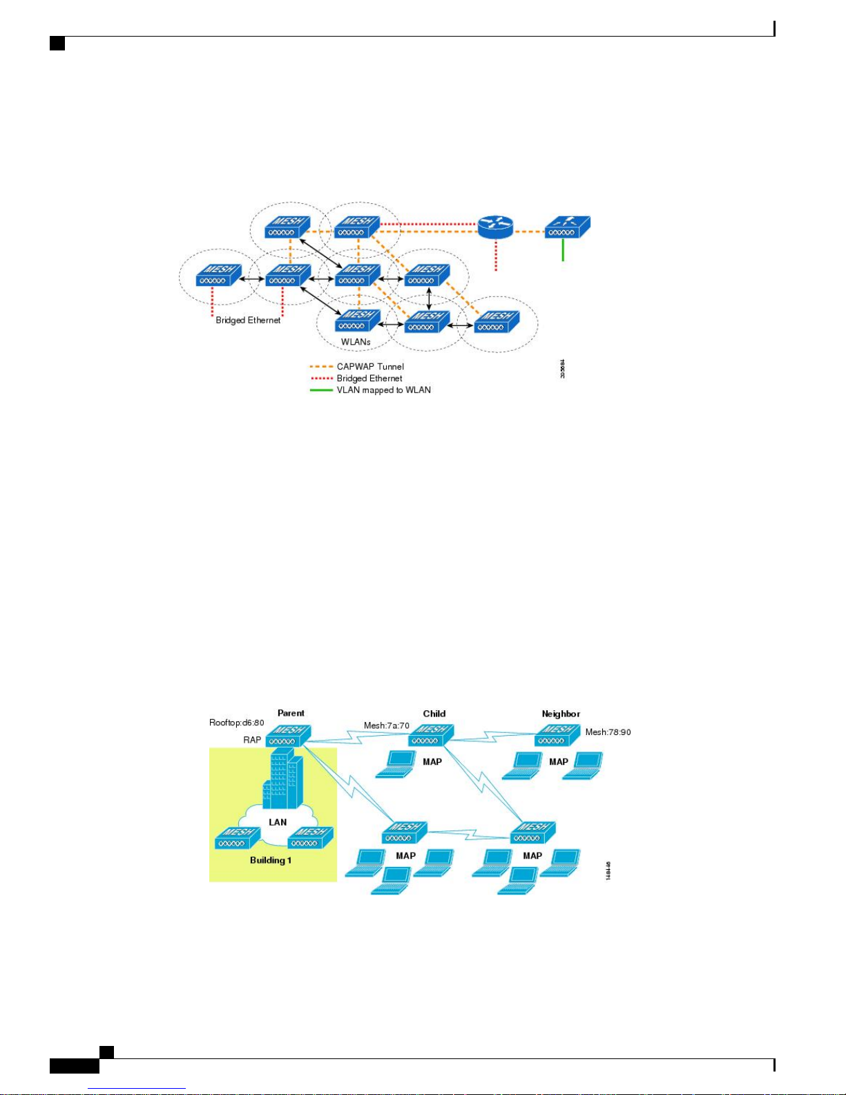
Adaptive Wireless Path Protocol
can be passed from each Ethernet interface on the mesh network and does not have to be mapped to an interface
on the controller (see Figure 19: Logical Bridge and WLAN Mapping, on page 44).
Figure 19: Logical Bridge and WLAN Mapping
Mesh Network Components
Mesh Neighbors, Parents, and Children
Relationships among mesh access points are as a parent, child, or neighbor (see Figure 20: Parent, Child, and
Neighbor Access Points, on page 44).
• A parent access point offers the best route back to the RAP based on its ease values. A parent can be
either the RAP itself or another MAP.
◦ Ease is calculated using the SNR and link hop value of each neighbor. Given multiple choices,
generally an access point with a higher ease value is selected.
• A child access point selects the parent access point as its best route back to the RAP.
• A neighbor access point is within RF range of another access point but is not selected as its parent or a
child because its ease values are lower than that of the parent.
Figure 20: Parent, Child, and Neighbor Access Points
Cisco Mesh Access Points, Design and Deployment Guide, Release 7.3
44 OL-27593-01
Page 61

Mesh Network Components
Criteria to Choose the Best Parent
AWPP follows this process in selecting parents for a RAP or MAP with a radio backhaul:
•
A list of channels with neighbors is generated by passive scanning in the scan state, which is a subset
of all backhaul channels.
•
The channels with neighbors are sought by actively scanning in the seek state and the backhaul channel
is changed to the channel with the best neighbor.
•
The parent is set to the best neighbor and the parent-child handshake is completed in the seek state.
•
Parent maintenance and optimization occurs in the maintain state.
This algorithm is run at startup and whenever a parent is lost and no other potential parent exists, and is usually
followed by CAPWAP network and controller discovery. All neighbor protocol frames carry the channel
information.
Parent maintenance occurs by the child node sending a directed NEIGHBOR_REQUEST to the parent and
the parent responding with a NEIGHBOR_RESPONSE.
Parent optimization and refresh occurs by the child node sending a NEIGHBOR_REQUEST broadcast on
the same channel on which its parent resides, and by evaluating all responses from neighboring nodes on the
channel.
A parent mesh access point provides the best path back to a RAP. AWPP uses ease to determine the best path.
Ease can be considered the opposite of cost, and the preferred path is the path with the higher ease.
Adaptive Wireless Path Protocol
Ease Calculation
Parent Decision
Ease is calculated using the SNR and hop value of each neighbor, and applying a multiplier based on various
SNR thresholds. The purpose of this multiplier is to apply a spreading function to the SNRs that reflects
various link qualities.
Figure 21: Parent Path Selection, on page 45 shows the parent path selection where MAP2 prefers the path
through MAP1 because the adjusted ease value (436906) though this path is greater then the ease value
(262144) of the direct path from MAP2 to RAP.
Figure 21: Parent Path Selection
A parent mesh access point is chosen by using the adjusted ease, which is the ease of each neighbor divided
by the number of hops to the RAP:
adjusted ease = min (ease at each hop) Hop count
OL-27593-01 45
Cisco Mesh Access Points, Design and Deployment Guide, Release 7.3
Page 62

Adaptive Wireless Path Protocol
SNR Smoothing
One of the challenges in WLAN routing is the ephemeral nature of RF, which must be considered when
analyzing an optimal path and deciding when a change in path is required. The SNR on a given RF link can
change substantially from moment to moment, and changing route paths based on these fluctuations results
in an unstable network, with severely degraded performance. To effectively capture the underlying SNR but
remove moment-to-moment fluctuations, a smoothing function is applied that provides an adjusted SNR.
In evaluating potential neighbors against the current parent, the parent is given 20 percent of bonus-ease on
top of the parent's calculated ease, to reduce the ping-pong effect between parents. A potential parent must
be significantly better for a child to make a switch. Parent switching is transparent to CAPWAP and other
higher-layer functions.
Loop Prevention
To ensure that routing loops are not created, AWPP discards any route that contains its own MAC address.
That is, routing information apart from hop information contains the MAC address of each hop to the RAP;
therefore, a mesh access point can easily detect and discard routes that loop.
Mesh Network Components
Cisco Mesh Access Points, Design and Deployment Guide, Release 7.3
46 OL-27593-01
Page 63

Mesh Deployment Modes
This chapter describes the mesh deployment modes and contains the following sections:
• Wireless Mesh Network, page 47
• Wireless Backhaul, page 47
• Point-to-Multipoint Wireless Bridging, page 48
• Point-to-Point Wireless Bridging, page 48
Wireless Mesh Network
In a Cisco wireless outdoor mesh network, multiple mesh access points comprise a network that provides
secure, scalable outdoor wireless LAN.
The three RAPs are connected to the wired network at each location and are located on the building roof. All
the downstream access points operate as MAPs and communicate using wireless links (not shown).
Both MAPs and RAPs can provide WLAN client access; however, the location of RAPs are often not suitable
for providing client access. All the three access points in are located on the building roofs and are functioning
as RAPs. These RAPs are connected to the network at each location.
Some of the buildings have onsite controllers to terminate CAPWAP sessions from the mesh access points
but it is not a mandatory requirement because CAPWAP sessions can be back hauled to a controller over a
wide-area network (WAN).
CHAPTER 2
Wireless Backhaul
In a Cisco wireless backhaul network, traffic can be bridged between MAPs and RAPs. This traffic can be
from wired devices that are being bridged by the wireless mesh or CAPWAP traffic from the mesh access
points. This traffic is always AES encrypted when it crosses a wireless mesh link such as a wireless backhaul.
AES encryption is established as part of the mesh access point neighbor relationship with other mesh access
points. The encryption keys used between mesh access points are derived during the EAP authentication
process.
Only 5 GHz backhaul is possible on all mesh access points except 1522 in which either 2.4 or 5 GHz radio
can be configured as a backhaul radio (see Configuring Advanced Features).
OL-27593-01 47
Cisco Mesh Access Points, Design and Deployment Guide, Release 7.3
Page 64

Universal Access
Universal Access
You can configure the backhaul on mesh access points to accept client traffic over its 802.11a radio. This
feature is identified as Backhaul Client Access in the controller GUI (Monitor > Wireless). When this feature
is disabled, backhaul traffic is transmitted only over the 802.11a or 802.11a/n radio and client association is
allowed only over the 802.11b/g or 802.11b/g/n radio. For more information about the configuration, see the
Configuring Advanced Features.
Point-to-Multipoint Wireless Bridging
In the point-to-multipoint bridging scenario, a RAP acting as a root bridge connects multiple MAPs as nonroot
bridges with their associated wired LANs. By default, this feature is disabled for all MAPs. If Ethernet bridging
is used, you must enable it on the controller for the respective MAP and for the RAP.
This figure shows a simple deployment with one RAP and two MAPs, but this configuration is fundamentally
a wireless mesh with no WLAN clients. Client access can still be provided with Ethernet bridging enabled,
although if bridging between buildings, MAP coverage from a high rooftop might not be suitable for client
access.
Figure 22: Point-to-Multipoint Bridging Example
Mesh Deployment Modes
Point-to-Point Wireless Bridging
In a point-to-point bridging scenario, a 1500 Series Mesh AP can be used to extend a remote network by using
the backhaul radio to bridge two segments of a switched network. This is fundamentally a wireless mesh
network with one MAP and no WLAN clients. Just as in point-to-multipoint networks, client access can still
be provided with Ethernet bridging enabled, although if bridging between buildings, MAP coverage from a
high rooftop might not be suitable for client access.
If you intend to use an Ethernet bridged application, we recommend that you enable the bridging feature on
the RAP and on all MAPs in that segment. You must verify that any attached switches to the Ethernet ports
Cisco Mesh Access Points, Design and Deployment Guide, Release 7.3
48 OL-27593-01
Page 65

Mesh Deployment Modes
Configuring Mesh Range (CLI)
of your MAPs are not using VLAN Trunking Protocol (VTP). VTP can reconfigure the trunked VLANs across
your mesh and possibly cause a loss in connection for your RAP to its primary WLC. An incorrect configuration
can take down your mesh deployment.
Figure 23: Point-to-Point Bridging Example
For security reasons the Ethernet port on the MAPs is disabled by default. It can be enabled only by configuring
Ethernet bridging on the Root and the respective MAPs. To enable Ethernet bridging using the controller
GUI, choose Wireless > All APs > Details for the AP page, click the Mesh tab, and then select the Ethernet
Bridging check box.
Ethernet bridging has to be enabled for the following two scenarios:
When you want to use the mesh nodes as bridges.
When you want to connect Ethernet devices such as a video camera on the MAP using its Ethernet port.
Ensure that you enable Ethernet bridging for every parent mesh AP taking the path from the mesh AP in
question to the controller. For example, if you enable Ethernet bridging on MAP2 in Hop 2, then you must
also enable Ethernet bridging on MAP1 (parent MAP), and on the RAP connecting to the controller.
To configure range parameters for longer links, choose Wireless > Mesh. Optimum distance (in feet) should
exist between the root access point (RAP) and the farthest mesh access point (MAP). Range from the RAP
bridge to the MAP bridge has to be mentioned in feet.
The following global parameter applies to all mesh access points when they join the controller and all existing
mesh access points in the network:
Range: 150 to 132,000 feet
Default: 12,000 feet
Configuring Mesh Range (CLI)
• To configure the distance between the nodes doing the bridging, enter the config mesh range command.
APs reboot after you specify the range.
Note
OL-27593-01 49
To estimate the range and the AP density, you can use range calculators that are available at:
Cisco 1520 Series Outdoor Mesh Range Calculation Utility: http://www.cisco.com/en/US/products/ps8368/
products_implementation_design_guides_list.html
Range Calculator for 1550 Series Outdoor Mesh Access Points: http://www.cisco.com/en/US/products/
ps11451/products_implementation_design_guides_list.html
Cisco Mesh Access Points, Design and Deployment Guide, Release 7.3
Page 66

Assumptions for the AP1522 Range Calculator
• To view the mesh range, enter the show mesh config command.
Assumptions for the AP1522 Range Calculator
• The AP1522 Range Calculator has been edited to stay within limitations for Tx power and EIRP under
the listed regulatory domains. There may be cases where it exceeds the limitations. You must verify that
the installation is within the laws of the location in which it is being installed.
• When you use the AP1522 Range Calculator, available power levels change based upon the regulatory
domain, the antenna (or antenna gain) selected, the modulation mode, which is based on the data rate
selected (OFDM requires a lower power level in some domains). You must verify all parameters after
making any parameter changes.
• Rx sensitivity in 2.4 GHz is the composite sensitivity of all three Rx paths. That is, MRC is included in
2.4 GHz. There is only one Rx for 5 GHz.
• You can choose only the channels that the access point is certified for.
• You can select only valid power levels.
Mesh Deployment Modes
Assumptions for the AP1552 Range Calculator
• The AP1552 Range Calculator has been edited to stay within limitations for Tx power and EIRP under
the listed regulatory domains. There may be cases where it exceeds the limitations. You must verify that
the installation is within the laws of the location in which it is being installed.
• All three antenna ports must be used for external antenna models of 1552 for effective performance.
Otherwise, range is significantly compromised. 1552 radios have two Tx paths and three Rx paths.
• The Tx power is the total composite power of both Tx paths.
• Rx sensitivity is the composite sensitivity of all three Rx paths. That is, MRC is included.
• The AP1552 Range Calculator assumes that ClientLink (Beamforming) is switched on.
• You can select a different antenna than the two that are available by default. If you enter a high gain
antenna and choose a power that goes over the EIRP limit, then you get a warning and the range equals
0.
• You can choose only the channels that the access point is certified for.
• You can only select only valid power levels.
Cisco Mesh Access Points, Design and Deployment Guide, Release 7.3
50 OL-27593-01
Page 67

Design Considerations
This chapter describes important design considerations and provides an example of a wireless mesh design.
Each outdoor wireless mesh deployment is unique, and each environment has its own challenges with
available locations, obstructions, and available network infrastructure. Design requirements driven by expected
users, traffic, and availability needs are also major design criteria. This chapter contains the following sections:
• Wireless Mesh Constraints, page 51
• ClientLink Technology, page 55
• Controller Planning, page 58
Wireless Mesh Constraints
The following are a few system characteristics to consider when you design and build a wireless mesh network.
Some of these characteristics apply to the backhaul network design and others to the CAPWAP controller
design:
CHAPTER 3
Wireless Backhaul Data Rate
Backhaul is used to create only the wireless connection between the access points. The backhaul interface by
default is 802.11a or 802.11a/n depending upon the access point. The rate selection is important for effective
use of the available RF spectrum. The rate can also affect the throughput of client devices, and throughput is
an important metric used by industry publications to evaluate vendor devices.
Dynamic Rate Adaptation (DRA) introduces a process to estimate optimal transmission rate for packet
transmissions. It is important to select rates correctly. If the rate is too high, packet transmissions fail resulting
in communication failure. If the rate is too low, the available channel bandwidth is not used, resulting in
inferior products, and the potential for catastrophic network congestion and collapse.
Data rates also affect the RF coverage and network performance. Lower data rates, for example 6 Mbps, can
extend farther from the access point than can higher data rates, for example 300 Mbps. As a result, the data
rate affects cell coverage and consequently the number of access points required. Different data rates are
achieved by sending a more redundant signal on the wireless link, allowing data to be easily recovered from
noise. The number of symbols sent out for a packet at the 1-Mbps data rate is higher than the number of
OL-27593-01 51
Cisco Mesh Access Points, Design and Deployment Guide, Release 7.3
Page 68

Wireless Backhaul Data Rate
symbols used for the same packet at 11 Mbps. Therefore, sending data at the lower bit rates takes more time
than sending the equivalent data at a higher bit rate, resulting in reduced throughput.
A lower bit rate might allow a greater distance between MAPs, but there are likely to be gaps in the WLAN
client coverage, and the capacity of the backhaul network is reduced. An increased bit rate for the backhaul
network either requires more MAPs or results in a reduced SNR between MAPs, limiting mesh reliability and
interconnection.
The data rate can be set on the backhaul on a per AP basis. It is not a global command.Note
The required minimum LinkSNR for backhaul links per data rate is shown in Table 14: Backhaul Data Rates
and Minimum LinkSNR Requirements, on page 52.
Table 14: Backhaul Data Rates and Minimum LinkSNR Requirements
Design Considerations
Minimum Required LinkSNR (dB)802.11a Data Rate (Mbps)
3154
2948
2636
2224
1818
1612
159
146
•
The required minimum LinkSNR value is driven by the data rate and the following formula: Minimum
SNR + fade margin.
Table 15: Calculation by Data Rate, on page 52 summarizes the calculation by data rate.
◦ Minimum SNR refers to an ideal state of noninterference, nonnoise, and a system packet error rate
(PER) of no more than 10 percent.
◦ Typical fade margin is approximately 9 to 10 dB.
Minimum Required LinkSNR Calculations by Data Rate
Table 15: Calculation by Data Rate
Cisco Mesh Access Points, Design and Deployment Guide, Release 7.3
52 OL-27593-01
Fade Margin =Minimum SNR (dB) +802.11n Date Rate (Mbps)
Minimum Required
LinkSNR (dB)
14956
Page 69

Design Considerations
Wireless Backhaul Data Rate
Fade Margin =Minimum SNR (dB) +802.11n Date Rate (Mbps)
Minimum Required
LinkSNR (dB)
15969
169712
189918
2291324
2691736
• If we take into account the effect of MRC for calculating Minimum Required Link SNR. Table 16:
Required LinkSNR Calculations for 802.11a/g, on page 53 shows the required LinkSNR for 802.11a/g
(2.4 GHz and 5 GHz) for AP1552 and 1522 with 3 Rx antennas (MRC gain).
LinkSNR = Minimum SNR - MRC + Fade Margin (9 dB)
Table 16: Required LinkSNR Calculations for 802.11a/g
Required Link
SNR (dB)
(Mbps)
Modulation802.11a/g MCS
Minimum SNR
(dB)
MRC Gain from
3 RXs (dB)
Fade Margin
(dB)
9.394.75BPSK 1/26
10.394.76BPSK 3/49
11.394.77QPSK 1/212
13.394.79QPSK 3/418
17.394.71316QAM 1/224
21.394.71716QAM 3/436
24.394.72064QAM 2/348
26.394.72264QAM 3/454
If we consider only 802.11n rates, then Table 17: Requirements for LinkSNR with AP1552 for 2.4 and 5
GHz, on page 54 shows LinkSNR requirements with AP1552 for 2.4 and 5 GHz.
OL-27593-01 53
Cisco Mesh Access Points, Design and Deployment Guide, Release 7.3
Page 70

Wireless Backhaul Data Rate
Table 17: Requirements for LinkSNR with AP1552 for 2.4 and 5 GHz
Design Considerations
Spatial
Streams
Modulation11n MCSNo. of
Minimum SNR
(dB)
MRC Gain from
3 RXs (dB)
Fade Margin
(dB)
Link SNR
(dB)
9.394.75BPSK 1/2MCS 01
11.394.77QPSK 1/2MCS 11
13.394.79QPSK 3/4MCS 21
17.394.71316QAM 1/2MCS 31
21.394.71716QAM 3/4MCS 41
24.394.72064QAM 2/3MCS 51
26.394.72264QAM 3/4MCS 61
27.394.72364QAM 5/6MCS 71
12.391.75BPSK 1/2MCS 82
14.391.77QPSK 1/2MCS 92
16.391.79QPSK 3/4MCS 102
20.391.71316QAM 1/2MCS 112
24.391.71716QAM 3/4MCS 122
27.391.72064QAM 2/3MCS 132
29.391.72264QAM 3/4MCS 142
30.391.72364QAM 5/6MCS 152
Cisco Mesh Access Points, Design and Deployment Guide, Release 7.3
54 OL-27593-01
Page 71

Design Considerations
ClientLink Technology
Note
With two spatial streams, the MRC gain is halved, that is the MRC gain is reduced by 3 dB. This is because
the system has 10 log (3/2 SS) instead of 10 log (3/1 SS). If there were to have been 3 SS with 3 RX, then
the MRC gain would have been zero.
• Number of backhaul hops is limited to eight but we recommend three to four hops.
The number of hops is recommended to be limited to three or four primarily to maintain sufficient
backhaul throughput, because each mesh access point uses the same radio for transmission and
reception of backhaul traffic, which means that throughput is approximately halved over every hop.
For example, the maximum throughput for 24 Mbps is approximately 14 Mbps for the first hop,
9 Mbps for the second hop, and 4 Mbps for the third hop.
• Number of MAPs per RAP.
There is no current software limitation on how many MAPs per RAP you can configure. However,
it is suggested that you limit the number to 20 MAPs per RAP.
• Number of controllers
◦ The number of controllers per mobility group is limited to 72.
• Number of mesh access points supported per controller.
ClientLink Technology
Many networks still support a mix of 802.11a/g and 802.11n clients. Because 802.11a/g clients (legacy clients)
operate at lower data rates, the older clients can reduce the capacity of the entire network. Cisco’s ClientLink
technology can help solve problems related to adoption of 802.11n in mixed-client networks by ensuring that
802.11a/g clients operate at the best possible rates, especially when they are near cell boundaries.
Advanced signal processing has been added to the Wi-Fi chipset. Multiple transmit antennas are used to focus
transmissions in the direction of the 802.11a/g client, increasing the downlink signal-to-noise ratio and the
data rate over range, thereby reducing coverage holes and enhancing the overall system performance. This
technology learns the optimum way to combine the signal received from a client and then uses this information
to send packets in an optimum way back to the client. This technique is also referred to as MIMO (multiple-input
multiple-output) beamforming, transmit beamforming, or cophasing, and it is the only enterprise-class and
service provider-class solution in the market that does not require expensive antenna arrays.
The 802.11n systems take advantage of multipath by sending multiple radio signals simultaneously. Each of
these signals, called a spatial stream, is sent from its own antenna using its own transmitter. Because there is
some space between these antennas, each signal follows a slightly different path to the receiver, a situation
called spatial diversity. The receiver has multiple antennas as well, each with its own radio that independently
decodes the arriving signals, and each signal is combined with signals from the other receiver radios. This
results in multiple data streams receiving at the same time. This enables a higher throughput than previous
802.11a/g systems, but requires an 802.11n capable client to decipher the signal. Therefore, both AP and
client need to support this capability. Due to the complexity of issues, in the first generation of mainstream
802.11n chipsets, neither the AP nor client chipsets implemented 802.11n transmit beamforming. Therefore,
the 802.11n standard transmit beamforming will be available eventually, but not until the next generation of
chipsets take hold in the market. We intend to lead in this area going forward.
OL-27593-01 55
Cisco Mesh Access Points, Design and Deployment Guide, Release 7.3
Page 72

Configuring ClientLink (CLI)
We realized that for the current generation of 802.11n APs, while the second transmit path was being well
utilized for 802.11n clients (to implement spatial diversity), it was not being fully used for 802.11a/g clients.
In other words, for 802.11 a/g clients, some of the capabilities of the extra transmit path was lying idle. In
addition, we realized that for many networks, the performance of the installed 802.11 a/g client base would
be a limiting factor on the network.
To take advantage of this fallow capacity and greatly enhance overall network capacity by bringing 802.11
a/g clients up to a higher performance level, we created an innovation in transmit beamforming technology,
called ClientLink.
ClientLink uses advanced signal processing techniques and multiple transmit paths to optimize the signal
received by 802.11a/g clients in the downlink direction without requiring feedback. Because no special
feedback is required, Cisco ClientLink works with all existing 802.11a/g clients.
Cisco ClientLink technology effectively enables the access point to optimize the SNR exactly at the position
where the client is placed. ClientLink provides a gain of almost 4 dB in the downlink direction. Improved
SNR yields many benefits, such as a reduced number of retries and higher data rates. For example, a client at
the edge of the cell that might previously have been capable of receiving packets at 12 Mbps could now receive
them at 36 Mbps. Typical measurements of downlink performance with ClientLink show as much as 65
percent greater throughput for 802.11a/g clients. By allowing the Wi-Fi system to operate at higher data rates
and with fewer retries, ClientLink increases the overall capacity of the system, which means an efficient use
of spectrum resources.
ClientLink in the 1552 access points is based on ClientLink capability available in AP3500s. Therefore, the
access point has the ability to beamform well to nearby clients and to update beamforming information on
802.11ACKs. Therefore, even if there is no dedicated uplink traffic, the ClientLink works well, which is
beneficial to both TCP and UDP traffic streams. There are no RSSI watermarks, which the client has to cross
to take advantage of this Beamforming with Cisco 802.11n access points.
ClientLink can beamform to 15 clients at a time. Therefore, the host must select the best 15 if the number of
legacy clients exceeds 15 per radio. AP1552 has two radios, which means that up to 30 clients can be
beamformed in time domain.
Although ClientLink is applied to legacy OFDM portions of packets, which refers to 11a/g rates (not 11b)
for both indoor and outdoor 802.11n access points, there is one difference between ClientLink for indoor 11n
and ClientLink for outdoor 11n. For indoor 11n access points, SW limits the affected rates to 24, 36, 48, and
54 Mbps. This is done to avoid clients sticking to a far away AP in an indoor environment. SW also does not
allow ClientLink to work for those rates for 11n clients because the throughput gain is so minimal. However,
there is a demonstrable gain for pure legacy clients. For outdoor 11n access points, we do need more coverage.
Thus, three more additional legacy data rates lower than 24 Mbps have been added. ClientLink for outdoors
is applicable to legacy data rates of 6, 9, 12, 18, 24, 36, 48, and 54 Mbps.
Design Considerations
ClientLink is enabled by default.Note
Configuring ClientLink (CLI)
From the 7.2 release onwards, it is not possible to configure ClientLink (beamforming) using the controller
GUI.
Step 1
56 OL-27593-01
Disable the 802.11a or 802.11b/g network by entering this command:
Cisco Mesh Access Points, Design and Deployment Guide, Release 7.3
Page 73

Design Considerations
config {802.11a | 802.11b} disable network
Configuring ClientLink (CLI)
Step 2
Step 3
Step 4
Step 5
Step 6
Step 7
Globally enable or disable beamforming on your 802.11a or 802.11g network by entering this command:
config {802.11a | 802.11b} beamforming global {enable | disable}
The default value is disabled.
Note
After you enable beamforming on the network, it is automatically enabled for all the radios applicable to that
network type.
Override the global configuration and enable or disable beamforming for a specific access point by entering this command:
config {802.11a | 802.11b} beamforming ap Cisco_AP {enable | disable}
The default value is disabled if beamforming is disabled on the network and enabled if beamforming is enabled on the
network.
Reenable the network by entering this command:
config {802.11a | 802.11b} enable network
Save your changes by entering this command:
save config
See the beamforming status for your network by entering this command:
show {802.11a | 802.11b}
Information similar to the following appears:
802.11a Network.................................. Enabled
11nSupport....................................... Enabled
802.11a Low Band........................... Enabled
802.11a Mid Band........................... Enabled
802.11a High Band.......................... Enabled
...
Pico-Cell-V2 Status.............................. Disabled
TI Threshold..................................... -50
Legacy Tx Beamforming setting................. Enabled
See the beamforming status for a specific access point by entering this command:
show ap config {802.11a | 802.11b} Cisco_AP
Information similar to the following appears:
Cisco AP Identifier.............................. 14
Cisco AP Name.................................... 1250-1
Country code..................................... US - United States
Regulatory Domain allowed by Country............. 802.11bg:-A 802.11a:-A
...
Phy OFDM parameters
Configuration ............................. AUTOMATIC
Current Channel ........................... 149
Extension Channel ......................... NONE
Channel Width.............................. 20 Mhz
Allowed Channel List....................... 36,40,44,48,52,56,60,64,100,
......................................... 104,108,112,116,132,136,140,
......................................... 149,153,157,161,165
TI Threshold .............................. -50
OL-27593-01 57
Cisco Mesh Access Points, Design and Deployment Guide, Release 7.3
Page 74

Commands Related to ClientLink
Legacy Tx Beamforming Configuration ....... CUSTOMIZED
Legacy Tx Beamforming ..................... ENABLED
Commands Related to ClientLink
The following commands are related to ClientLink:
• The following commands are to be entered in the AP console:
◦ To check the status of Beamforming on the AP, enter the show controller d0/d1 command.
◦ To find a client in the AP rbf table, enter the show interface dot110 command.
◦ To check the Beamforming rate assigned on the AP, enter the debug d0 trace print rates command.
• The following commands on the AP console are used for troubleshooting:
Design Considerations
◦ To show that ClientLink is enabled on a radio, enter the show controllers | inc Beam command.
The output is displayed as follows:
Legacy Beamforming: Configured Yes, Active Yes, RSSI Threshold -50 dBm
Legacy Beamforming: Configured Yes, Active Yes, RSSI Threshold -60 dBm
◦ To show that ClientLink is Beamforming to a particular client, enter the show interface dot11radio
1 lbf rbf command.
The output is displayed as follows:
RBF Table:
Index Client MAC Reserved Valid Tx BF Aging
1 0040.96BA.45A0 Yes Yes Yes No
Controller Planning
The following items affect the number of controllers required in a mesh network:
• Mesh access points (RAPs and MAPs) in the network.
The wired network that connects the RAP and controllers can affect the total number of access points
supported in the network. If this network allows the controllers to be equally available to all access
points without any impact on WLAN performance, the access points can be evenly distributed across
all controllers for maximum efficiency. If this is not the case, and controllers are grouped into various
clusters or PoPs, the overall number of access points and coverage are reduced.
• Number of mesh access points (RAPs and MAPs) supported per controller. See Table 18: Mesh Access
Point Support by Controller Model , on page 59.
For clarity, nonmesh access points are referred to as local access points in this document.
Cisco Mesh Access Points, Design and Deployment Guide, Release 7.3
58 OL-27593-01
Page 75

Design Considerations
Controller Planning
Table 18: Mesh Access Point Support by Controller Model
Controller Model
13
14
12
Local AP support is the total number of nonmesh APs supported on the controller model.
13
For 5508, controllers, the number of MAPs is equal to (local AP support - number of RAPs).
14
For 2504, controllers, the number of MAPs is equal to (local AP support - number of RAPs).
Note
Mesh is fully supported on Cisco 5508 Controllers. The Base License (LIC-CT508-Base) is sufficient for
Local AP Support (nonmesh)
indoor and outdoor APs (AP152X). The WPlus License (LIC-WPLUS-SW) is merged with the base
license. The WPlus License is not required for indoor mesh APs.
12
Maximum Possible
Mesh AP Support
5005005508
50502504
500500WiSM2
OL-27593-01 59
Cisco Mesh Access Points, Design and Deployment Guide, Release 7.3
Page 76

Controller Planning
Design Considerations
Cisco Mesh Access Points, Design and Deployment Guide, Release 7.3
60 OL-27593-01
Page 77

Site Survey
CHAPTER 4
Site Preparation and Planning
This chapter describes the site preparation and planning for your mesh network and contains the following
sections:
• Site Survey, page 61
• Wireless Mesh Network Coverage Considerations, page 71
• Indoor Mesh Interoperability with Outdoor Mesh, page 97
We recommend that you perform a radio site survey before installing the equipment. A site survey reveals
problems such as interference, Fresnel zone, or logistics problems. A proper site survey involves temporarily
setting up mesh links and taking measurements to determine whether your antenna calculations are accurate.
Determine the correct location and antenna before drilling holes, routing cables, and mounting equipment.
Note
When power is not readily available, we recommend you to use an unrestricted power supply (UPS) to
temporarily power the mesh link.
Pre-Survey Checklist
Before attempting a site survey, determine the following:
• How long is your wireless link?
• Do you have a clear line of sight?
• What is the minimum acceptable data rate within which the link runs?
• Is this a point-to-point or point-to-multipoint link?
• Do you have the correct antenna?
• Can the access point installation area support the weight of the access point?
OL-27593-01 61
Cisco Mesh Access Points, Design and Deployment Guide, Release 7.3
Page 78

Outdoor Site Survey
• Do you have access to both of the mesh site locations?
• Do you have the proper permits, if required?
• Do you have a partner? Never attempt to survey or work alone on a roof or tower.
• Have you configured the 1500 series before you go onsite? It is always easier to resolve configuration
or device problems first.
• Do you have the proper tools and equipment to complete your task?
Outdoor Site Survey
Deploying WLAN systems outdoors requires a different skill set to indoor wireless deployments. Considerations
such as weather extremes, lightning, physical security, and local regulations need to be taken into account.
When determining the suitability of a successful mesh link, define how far the mesh link is expected to transmit
and at what radio data rate. Remember that the data rate is not directly included in the wireless routing
calculation, and we recommend that the same data rate is used throughout the same mesh (the recommended
rate is 24 Mbps).
Design recommendations for mesh links are as follows:
Site Preparation and Planning
Cellular phones or handheld two-way radios can be helpful to do surveys.Note
• MAP deployment cannot exceed 35 feet in height above the street.
• MAPs are deployed with antennas pointed down toward the ground.
• Typical 5-GHz RAP-to-MAP distances are 1000 to 4000 feet.
• RAP locations are typically towers or tall buildings.
• Typical 5-GHz MAP-to-MAP distances are 500 to 1000 feet.
• MAP locations are typically short building tops or streetlights.
• Typical 2.4-GHz MAP-to-client distances are 500 to 1000 feet (depends upon the type of access point).
• Clients are typically laptops, Smart Phones, Tablets, and CPEs. Most of the clients operate in the 2.4-GHz
band.
Determining a Line of Sight
When you determine the suitability of a successful link, you must define how far the link is expected to
transmit and at what radio data rate. Very close links, one kilometer or less, are fairly easy to achieve assuming
there is a clear line of sight (LOS)–a path with no obstructions.
Because mesh radio waves have very high frequency in the 5-GHz band, the radio wavelength is small;
therefore, the radio waves do not travel as far as radio waves on lower frequencies, given the same amount
of power. This higher frequency range makes the mesh ideal for unlicensed use because the radio waves do
not travel far unless a high-gain antenna is used to tightly focus the radio waves in a given direction.
Cisco Mesh Access Points, Design and Deployment Guide, Release 7.3
62 OL-27593-01
Page 79

Site Preparation and Planning
Weather
Weather
This high-gain antenna configuration is recommended only for connecting a RAP to the MAP. To optimize
mesh behavior, omnidirectional antennas are used because mesh links are limited to one mile (1.6 km). The
curvature of the earth does not impact line-of-sight calculations because the curvature of the earth changes
every six miles (9.6 km).
In addition to free space path loss and line of sight, weather can also degrade a mesh link. Rain, snow, fog,
and any high humidity condition can slightly obstruct or affect the line of sight, introducing a small loss
(sometimes referred to as rain fade or fade margin), which has little effect on the mesh link. If you have
established a stable mesh link, the weather should not be a problem; however, if the link is poor to begin with,
bad weather can degrade performance or cause loss of link.
Ideally, you need a line of sight; a white-out snow storm does not allow a line of sight. Also, while storms
may make the rain or snow itself appear to be the problem, many times it might be additional conditions
caused by the adverse weather. For example, perhaps the antenna is on a mast pipe and the storm is blowing
the mast pipe or antenna structure and that movement is causing the link to come and go, or there might be a
large build-up of ice or snow on the antenna.
Fresnel Zone
A Fresnel zone is an imaginary ellipse around the visual line of sight between the transmitter and receiver.
As radio signals travel through free space to their intended target, they could encounter an obstruction in the
Fresnel area, degrading the signal. Best performance and range are attained when there is no obstruction of
this Fresnel area. Fresnel zone, free space loss, antenna gain, cable loss, data rate, link distance, transmitter
power, receiver sensitivity, and other variables play a role in determining how far your mesh link goes. Links
can still occur as long as 60 percent to 70 percent of the Fresnel area is unobstructed, as illustrated in Figure
24: Point-to-Point Link Fresnel Zone, on page 63.
Figure 24: Point-to-Point Link Fresnel Zone
OL-27593-01 63
Cisco Mesh Access Points, Design and Deployment Guide, Release 7.3
Page 80

Fresnel Zone Size in Wireless Mesh Deployments
Figure 25: Typical Obstructions in a Fresnel Zone, on page 64 illustrates an obstructed Fresnel zone.
Figure 25: Typical Obstructions in a Fresnel Zone
It is possible to calculate the radius of the Fresnel zone (in feet) at any particular distance along the path using
the following equation:
F1 = 72.6 X square root (d/4 x f)
where
F1 = the first Fresnel zone radius in feet
D = total path length in miles
F = frequency (GHz)
Normally, 60 percent of the first Fresnel zone clearance is recommended, so the above formula for 60 percent
Fresnel zone clearance can be expressed as follows:
0.60 F1= 43.3 x square root (d/4 x f)
These calculations are based on a flat terrain.
Figure 26: Removing Obstructions in a Fresnel Zone, on page 64 shows the removal of an obstruction in the
Fresnel zone of the wireless signal.
Site Preparation and Planning
Figure 26: Removing Obstructions in a Fresnel Zone
Fresnel Zone Size in Wireless Mesh Deployments
To give an approximation of size of the maximum Fresnel zone to be considered, at a possible minimum
frequency of 4.9 GHz, the minimum value changes depending on the regulatory domain. The minimum figure
quoted is a possible band allocated for public safety in the USA, and a maximum distance of one mile gives
a Fresnel zone of clearance requirement of 9.78 ft = 43.3 x SQR(1/(4*4.9)). This clearance is relatively easy
to achieve in most situations. In most deployments, distances are expected to be less than one mile, and the
Cisco Mesh Access Points, Design and Deployment Guide, Release 7.3
64 OL-27593-01
Page 81

Site Preparation and Planning
frequency greater than 4.9 GHz, making the Fresnel zone smaller. Every mesh deployment should consider
the Fresnel zone as part of its design, but in most cases, it is not expected that meeting the Fresnel clearance
requirement is an issue.
Hidden Nodes Interference
The mesh backhaul uses the same 802.11a channel for all nodes in that mesh, which can introduce hidden
nodes into the WLAN backhaul environment.
Figure 27: Hidden Nodes
Hidden Nodes Interference
Figure 27: Hidden Nodes, on page 65 shows the following three MAPs:
• MAP X
• MAP Y
• MAP Z
If MAP X is the route back to the RAP for MAP Y and Z, both MAP X and MAP Z might be sending traffic
to MAP Y at the same time. MAP Y can see traffic from both MAP X and Z, but MAP X and Z cannot see
each other because of the RF environment, which means that the carrier sense multi-access (CSMA) mechanism
does not stop MAP X and Z from transmitting during the same time window; if either of these frames is
destined for a MAP, it is corrupted by the collision between frames and requires retransmission.
Although all WLANs at some time can expect some hidden node collisions, the fixed nature of the MAP
makes hidden node collisions a persistent feature of the mesh WLAN backhaul under some traffic conditions
such as heavy loads and large packet streams.
Both the hidden node problem and the exposed node problem are inherent to wireless mesh networks because
mesh access points share the same backhaul channel. Because these two problems can affect the overall
network performance, the Cisco mesh solution seeks to mitigate these two problems as much as possible. For
example, the AP1500s have at least two radios: one for backhaul access on a 5-GHz channel and the other
for 2.4-GHz client access. In addition, the radio resource management (RRM) feature, which operates on the
2.4-GHz radio, enables cell breathing and automatic channel change, which can effectively decrease the
collision domains in a mesh network.
There is an additional solution that can help to further mitigate these two problems. To reduce collisions and
to improve stability under high load conditions, the 802.11 MAC uses an exponential backoff algorithm,
where contending nodes back off exponentially and retransmit packets whenever a perceived collision occurs.
Theoretically, the more retries a node has, the smaller the collision probability will be. In practice, when there
are only two contending stations and they are not hidden stations, the collision probability becomes negligible
OL-27593-01 65
Cisco Mesh Access Points, Design and Deployment Guide, Release 7.3
Page 82

Slot Bias Options
after just three retries. The collision probability increases when there are more contending stations. Therefore,
when there are many contending stations in the same collision domain, a higher retry limit and a larger
maximum contention window are necessary. Further, collision probability does not decrease exponentially
when there are hidden nodes in the network. In this case, an RTS/CTS exchange can be used to mitigate the
hidden node problem.
Functional Routing of Three Radio MAPs
Because a directional antenna is required to be attached to the slot 2 radios, you should align and RF tune
each link to minimize the hidden node effect. For example, a MAP at location C should be aligned to the
MAP at location B. The MAP at location C should not be able to see AP at location A. First, align the antennas
and then optimize each link by tuning the RF power. A channel is reused after 4 hops. A maximum number
of 8 hops is supported.
Figure 28: Functional Routing Example
Site Preparation and Planning
Slot Bias Options
When a 1524SB AP is switched on, either slot 1 or slot 2 can be used for an uplink depending on the strength
of the signal. AWPP treats both slots equally. For a MAP, slot 2 is the preferred (biased) uplink slot, that is,
the slot that is used to connect to the parent AP. Slot 1 is the preferred downlink slot. When both radio slots
are available for use and if slot 1 is used for an uplink backhaul, a 15-minute timer is started. At the end of
15 minutes, the AP scans for a channel in slot 2 so that slot 2 might be used for an uplink backhaul again.
This process is called slot bias.
We recommend that you use directional antenna on slot 2 for a proper linear functionality. We also recommend
that you ensure that slot 2 is selected for a strong uplink. However, there may be some scenarios where
directional antennas are used on both the backhaul radios for mobility. When the AP is powered on, the parent
can be selected in either direction. If slot 1 is selected, the AP should not go to the scanning mode after 15
minutes, that is, you should disable the slot bias.
Cisco Mesh Access Points, Design and Deployment Guide, Release 7.3
66 OL-27593-01
Page 83

Site Preparation and Planning
Disabling Slot Bias
To disable slot bias so that the APs can be stable on slot 1, enter the config mesh slot-bias disable command.
Slot Bias Options
Note
The slot bias is enabled by default.
Usage Guidelines
Follow these guidelines for the config mesh slot-bias disable command:
• The config mesh slot-bias disable command is a global command and is applicable to all 1524SB APs
associated with the same controller.
• Slot bias is applicable only when both slot 1 and slot 2 are usable. If a slot radio does not have a channel
that is available because of dynamic frequency selection (DFS), the other slot takes up both the uplink
and downlink roles.
• If slot 2 is not available because of hardware issues, slot bias functions normally. Take corrective action
by disabling the slot bias or fixing the antenna.
• A 15-minute timer is initiated (slot bias) only when slot 1 and slot 2 are usable (have channels to operate).
• The 15-minute timer is not initiated if slot 2 cannot find any channels because of DFS, which results in
slot 1 taking over the uplink and the downlink.
• Slot 2 takes over slot 1 if slot 1 does not have any channels to operate because of DFS.
• If slot 2 has a hardware failure, then slot bias is initiated, and slot 1 is selected for uplinking.
• Disabling slot bias enables you to take preventive action for a smooth operation.
Commands Related to Slot Bias
The following commands related to slot bias:
• To see which slot is being used for an uplink or a downlink, enter the following command:
(Cisco Controller) > show mesh config
Mesh Range....................................... 12000
Mesh Statistics update period.................... 3 minutes
Backhaul with client access status............... enabled
Backhaul with extended client access status...... disabled
Background Scanning State........................ enabled
Backhaul Amsdu State............................. enabled
Mesh Security
Security Mode................................. EAP
External-Auth................................. disabled
Use MAC Filter in External AAA server......... disabled
Force External Authentication................. disabled
Mesh Alarm Criteria
Max Hop Count................................. 4
Recommended Max Children for MAP.............. 10
Recommended Max Children for RAP.............. 20
Low Link SNR.................................. 12
High Link SNR................................. 60
Max Association Number........................ 10
Association Interval.......................... 60 minutes
Parent Change Numbers......................... 3
Parent Change Interval........................ 60 minutes
OL-27593-01 67
Cisco Mesh Access Points, Design and Deployment Guide, Release 7.3
Page 84

Preferred Parent Selection
Mesh Multicast Mode.............................. In-Out
Mesh Full Sector DFS............................. enabled
Mesh Ethernet Bridging VLAN Transparent Mode..... enabled
Mesh DCA channels for serial backhaul APs........ disabled
Mesh Slot Bias................................... disabled
• To verify that slot 1 is being used for an uplink, do the following:
Enable debugging on the AP by entering the following command in the controller:
(Cisco Controller) > debug ap enable AP_name
Enter the following commands in the controller:
(Cisco Controller) > debug ap command show mesh config AP_name
(Cisco Controller) > debug ap command show mesh adjacency parent AP_name
Preferred Parent Selection
Site Preparation and Planning
You can configure a preferred parent for a MAP. This feature gives more control to you and enables you to
enforce a linear topology in a mesh environment. You can skip AWPP and force a parent to go to a preferred
parent.
Preferred Parent Selection Criteria
The child AP selects the preferred parent based on the following criteria:
• The preferred parent is the best parent.
• The preferred parent has a link SNR of at least 20 dB (other parents, however good, are ignored).
• The preferred parent has a link SNR in the range of 12 dB and 20 dB, but no other parent is significantly
better (that is, the SNR is more than 20 percent better). For an SNR lower than 12 dB, the configuration
is ignored.
• The preferred parent is not blacklisted.
• The preferred parent is not in silent mode because of dynamic frequency selection (DFS).
• The preferred parent is in the same bridge group name (BGN). If the configured preferred parent is not
in the same BGN and no other parent is available, the child joins the parent AP using the default BGN.
Note
Slot bias and preferred parent selection features are independent of each other. However,
with the preferred parent configured, the connection is made to the parent using slot 1
or slot 2, whichever the AP sees first. If slot 1 is selected for the uplink in a MAP, then
slot bias occurs. We recommend that you disable slot bias if you already know that slot
1 is going to be selected.
Cisco Mesh Access Points, Design and Deployment Guide, Release 7.3
68 OL-27593-01
Page 85

Site Preparation and Planning
Configuring a Preferred Parent
To configure a preferred parent, enter the following command:
(Cisco Controller) > config mesh parent preferred AP_name MAC
where:
•
AP_name is the name of the child AP that you have to specify.
•
MAC is the MAC address of the preferred parent that you have to specify.
Preferred Parent Selection
Note
The following example shows how to configure the preferred parent for the MAP1SB access point, where
00:24:13:0f:92:00 is the preferred parent’s MAC address:
(Cisco Controller) > config mesh parent preferred MAP1SB 00:24:13:0f:92:0f
Related Commands
The following commands are related to preferred parent selection:
• To clear a configured parent, enter the following command:
(Cisco Controller) > config mesh parent preferred AP_name none
• To get information about the AP that is configured as the preferred parent of a child AP, enter the
following command:
(Cisco Controller) > show ap config general AP_name
When you configure a preferred parent, ensure that you specify the MAC address of the
actual mesh neighbor for the desired parent. This MAC address is the base radio MAC
address that has the letter f as the final character. For example, if the base radio MAC
address is 00:24:13:0f:92:00, then you must specify 00:24:13:0f:92:0f as the preferred
parent. This is the actual MAC address that is used for mesh neighbor relationships.
The following example shows how to get the configuration information for the MAP1SB access point, where
00:24:13:0f:92:00 is the MAC address of the preferred parent:
(Cisco Controller) > show ap config general MAP1SB
Cisco AP Identifier.............................. 9
Cisco AP Name.................................... MAP1SB
Country code..................................... US - United States
Regulatory Domain allowed by Country............. 802.11bg:-A 802.11a:-A
AP Country code.................................. US - United States
AP Regulatory Domain............................. 802.11bg:-A 802.11a:-A
Switch Port Number .............................. 1
MAC Address...................................... 12:12:12:12:12:12
IP Address Configuration......................... DHCP
IP Address....................................... 209.165.200.225
IP NetMask....................................... 255.255.255.224
OL-27593-01 69
Cisco Mesh Access Points, Design and Deployment Guide, Release 7.3
Page 86

Co-Channel Interference
CAPWAP Path MTU.................................. 1485
Domain...........................................
Name Server......................................
Telnet State..................................... Disabled
Ssh State........................................ Disabled
Cisco AP Location................................ default location
Cisco AP Group Name.............................. default-group
Primary Cisco Switch Name........................ 4404
Primary Cisco Switch IP Address.................. 209.165.200.230
Secondary Cisco Switch Name......................
Secondary Cisco Switch IP Address................ Not Configured
Tertiary Cisco Switch Name....................... 4404
Tertiary Cisco Switch IP Address................. 3.3.3.3
Administrative State ............................ ADMIN_ENABLED
Operation State ................................. REGISTERED
Mirroring Mode .................................. Disabled
AP Mode ......................................... Local
Public Safety ................................... Global: Disabled, Local: Disabled
AP subMode ...................................... WIPS
Remote AP Debug ................................. Disabled
S/W Version .................................... 5.1.0.0
Boot Version ................................... 12.4.10.0
Mini IOS Version ................................ 0.0.0.0
Stats Reporting Period .......................... 180
LED State........................................ Enabled
PoE Pre-Standard Switch.......................... Enabled
PoE Power Injector MAC Addr...................... Disabled
Power Type/Mode.................................. PoE/Low Power (degraded mode)
Number Of Slots.................................. 2
AP Model......................................... AIR-LAP1252AG-A-K9
IOS Version...................................... 12.4(10:0)
Reset Button..................................... Enabled
AP Serial Number................................. serial_number
AP Certificate Type.............................. Manufacture Installed
Management Frame Protection Validation........... Enabled (Global MFP Disabled)
AP User Mode..................................... CUSTOMIZED
AP username..................................... maria
AP Dot1x User Mode............................... Not Configured
AP Dot1x username............................... Not Configured
Cisco AP system logging host..................... 255.255.255.255
AP Up Time....................................... 4 days, 06 h 17 m 22 s
AP LWAPP Up Time................................. 4 days, 06 h 15 m 00 s
Join Date and Time............................... Mon Mar 3 06:19:47 2008
Ethernet Port Duplex............................. Auto
Ethernet Port Speed.............................. Auto
AP Link Latency.................................. Enabled
Current Delay................................... 0 ms
Maximum Delay................................... 240 ms
Minimum Delay................................... 0 ms
Last updated (based on AP Up Time).............. 4 days, 06 h 17 m 20 s
Rogue Detection.................................. Enabled
AP TCP MSS Adjust................................ Disabled
Mesh preferred parent............................ 00:24:13:0f:92:00
Site Preparation and Planning
Co-Channel Interference
In addition to hidden node interference, co-channel interference can also impact performance. Co-channel
interference occurs when adjacent radios on the same channel interfere with the performance of the local mesh
network. This interference takes the form of collisions or excessive deferrals by CSMA. In both cases,
performance of the mesh network is degraded. With appropriate channel management, co-channel interference
on the wireless mesh network can be minimized.
Cisco Mesh Access Points, Design and Deployment Guide, Release 7.3
70 OL-27593-01
Page 87

Site Preparation and Planning
Wireless Mesh Network Coverage Considerations
Wireless Mesh Network Coverage Considerations
This section provides a summary of items that must be considered for maximum wireless LAN coverage in
an urban or suburban area, to adhere to compliance conditions for respective domains.
The following recommendations assume a flat terrain with no obstacles (green field deployment).
We always recommend that you perform a site survey before taking any real estimations for the area and
creating a bill of materials.
Cell Planning and Distance
For the Cisco 1520 Series Access Points
The RAP-to-MAP ratio is the starting point. For general planning purposes, the current ratio is 20 MAPs per
RAP.
We recommend the following values for cell planning and distance in nonvoice networks:
• RAP-to-MAP ratio—Recommended maximum ratio is 20 MAPs per RAP.
• AP-to-AP distance—A spacing of no more than of 2000 feet (609.6 meters) between each mesh access
point is recommended. When you extend the mesh network on the backhaul (no client access), use a
cell radius of 1000 feet (304.8 meters).
• Hop count—Three to four hops.
◦ One square mile in feet (52802), is nine cells and you can cover one square mile with approximately
three or four hops (see Figure 29: Cell Radius of 1000 Feet and Access Point Placement for
Nonvoice Mesh Networks, on page 72 and Figure 30: Path Loss Exponent 2.3 to 2.7, on page
72.)
• For 2.4 GHz, the local access cell size radius is 600 feet (182.88 meters). One cell size is around 1.310
x 106, so there are 25 cells per square mile. (See Figure 31: Cell Radius of 600 Feet and Access Point
OL-27593-01 71
Cisco Mesh Access Points, Design and Deployment Guide, Release 7.3
Page 88

Cell Planning and Distance
Site Preparation and Planning
Placement for Nonvoice Mesh Networks, on page 72 and Figure 32: Path Loss Exponent 2.5 to 3.0,
on page 73.)
Figure 29: Cell Radius of 1000 Feet and Access Point Placement for Nonvoice Mesh Networks
Figure 30: Path Loss Exponent 2.3 to 2.7
Figure 31: Cell Radius of 600 Feet and Access Point Placement for Nonvoice Mesh Networks
Cisco Mesh Access Points, Design and Deployment Guide, Release 7.3
72 OL-27593-01
Page 89

Site Preparation and Planning
Cell Planning and Distance
Figure 32: Path Loss Exponent 2.5 to 3.0
For the Cisco 1550 Series Access Points
As seen in the previous section, for a Greenfield deployment with the AP1520 series, we recommend a cell
radius of 600 feet, and an AP to AP distance of 1200 feet. Normally, an AP to AP distance that is twice the
OL-27593-01 73
Cisco Mesh Access Points, Design and Deployment Guide, Release 7.3
Page 90

Cell Planning and Distance
AP to client distance is recommended. That is, if we halve the AP to AP distance, we will get the approximate
cell radius.
The AP1550 series offers comparatively better range and capacity as it has the 802.11n functionality. It has
advantages of ClientLink (Beamforming) in downstream, better receiver sensitivities because of MRC in
upstream, multiple transmitter streams and a few other advantages of 802.11n such as channel combining and
so on. The 1552 access points can provide comparatively larger and higher capacity cells.
Site Preparation and Planning
Note
Link budgets are different for different country domains. The discussion in this section takes into account
the most widely distributed and large country domains: -A and -E.
Comparison of Link Budgets of AP1520 Series and AP1552 Series in 2.4- and 5-GHz Bands (-A Domain)
For the 2.4-GHz band 1520s and 1552s have almost the same Tx power, but 1552s have 3 dB better Rx
sensitivity because of improved MRC (see Table 19: Link Budget Comparison for the 2.4-GHz band in -A
Domain, on page 74).
Table 19: Link Budget Comparison for the 2.4-GHz band in -A Domain
CommentsCisco 1522 (-A Domain)Cisco 1552 (-A domain)Parameter
Center Frequencies2412-2462 MHz2412-2462 MHzFrequency Band
802.11b/g802.11b/g/nAir Interface
20 MHz20 MHzChannel Bandwidth
12No. of Tx Spatial Streams
PHY Data Rates
Tx Power Conducted
15
Up to 54 MbpsUp to 144 Mbps
16
27 dBm28 dBm, Composite
Maximum power, data
rate dependent
Rx Sensitivity
Antenna Cable loss
Cisco Mesh Access Points, Design and Deployment Guide, Release 7.3
74 OL-27593-01
–94 dBm at 6 Mbps
–79 dBm at 54 Mbps
–73 dBm at 300 Mbps
antenna
–90 dBm at 6 Mbps
–80 dBm at 54 Mbps
17
33No. of Receive Channels
MRCMRCRx Diversity
0.5 dB0.5 dB, with external
Includes 4.7 dB MRC
gain for AP1552
Page 91

Site Preparation and Planning
Cell Planning and Distance
CommentsCisco 1522 (-A Domain)Cisco 1552 (-A domain)Parameter
Antenna gain without
ClientLink
(Beamforming)
3 dual-band
omnidirectional antenna
1552 E/H: 4 dBi each
5.5 dBi or 8 dBi
omnidirectional
1552 C/I: 2 dBi each
(3-element low profile
Radom)
5.5 dBi or 8 dBi (No BF)8 dBi or 6 dBiAntenna gain with
ClientLink
(Beamforming)
15
40-MHz channel bonding in 2.4 GHz is not applicable. Therefore, the maximum data rate is 144 Mbps.
16
Composite power is the power when we have two Tx streams enabled in AP1552.
17
1552 has 3 dB better receiver sensitivity when compared to 1520 series APs.
Note
AP1552 has almost the same antenna gain with ClientLink (Beamforming) as compared to AP1522s.
There is no 20-MHz channel bonding available in the 2.4-GHz band to get the 40-MHz channel as we
only have 3 nonoverlapping channels. The maximum data rate that we can achieve in 2.4 GHz is 144
Mbps.
For the 5-GHz band, 1520s and 1552s have almost the same Tx power, but 1552s have approximately 4 dB
better Rx sensitivity because of the availability of MRC in 5 GHz (see Table 20: Link Budget Comparison
for the 5-GHz band in -A Domain, on page 75).
Table 20: Link Budget Comparison for the 5-GHz band in -A Domain
802.11a802.11a/nAir Interface
20 MHz20 MHz, 40 MHzChannel Bandwidth
12No. of Tx Spatial Streams
Up to 54 MbpsUp to 300 MbpsPHY Data Rates
28 dBm28 dBm, CompositeTx Power Conducted
Rx Sensitivity
–92 dBm at 6 Mbps
–76 dBm at 54 Mbps
–72 dBm at 300 Mbps
–88 dBm at 6 Mbps
–73 dBm at 54 Mbps
18
CommentsCisco 1522 (-A Domain)Cisco 1552 (-A Domain)Parameter
Center Frequencies5745-5825 MHz5745-5825 MHzFrequency Band
Maximum power, data
rate dependent
Includes 4.7 dB MRC
gain for AP1552
OL-27593-01 75
Cisco Mesh Access Points, Design and Deployment Guide, Release 7.3
Page 92

Cell Planning and Distance
Site Preparation and Planning
CommentsCisco 1522 (-A Domain)Cisco 1552 (-A Domain)Parameter
13No. of Receive Channels
MRCRx Diversity
Antenna gain without
ClientLink
(Beamforming)
omnidirectional antenna
1552 E/H: 7 dBi each
1552 C/I: 4 dBi each
(3 element low profile
Radom)
Antenna gain with
ClientLink
8 dBi panel array
(Beamforming)
18
1552 has ~4 dB better Rx sensitivity as compared to 1520 series APs.
19
Maximum Ratio Combining not available for 1522 in 5 GHz.
The 20-MHz channel bonding to form a 40-MHz channel is available in 5 GHz. Therefore, we can go up to
a data rate of 300 Mbps.
As discussed in the previous section, Path Loss Exponents (PLE) and Link Budget windows work together.
For a full clear path, PLE is 2.0. For AP to AP, there is comparatively more clearance than AP to client. For
AP to AP, PLE can be taken as 2.3 because it can be assumed that the height of both APs is about 10 meters,
which means a good line of sight (but without Fresnel zone clearance).
No MRC
0.5 dB0.5 dBAntenna Cable loss
8 dBi, 14 dBi, 17 dBi3 dual-band
8 dBi (No BF)11 dBi (omnidirectional),
19
Note
For AP to client, PLE should be greater than or equal to 2.5 because the client is only 1 meter high. Therefore,
there will be less Fresnel zone clearance. This applies to both the 2.4-GHz and 5-GHz bands.
Let us consider AP to AP link budget in 5 GHz for -A domain because 5 GHz is used as a backhaul for mesh.
We can take a legacy data rate of 9 Mbps to estimate the range (see Table 21: AP to AP RF Link Budget, 5.8
GHz: 9 Mbps (-A domain), on page 76).
This is the lowest data rate for outdoor 802.11n APs, which carries the Cisco's ClientLink (Beamforming
for Legacy clients) advantage. It provides a gain of up to 4 dB in the downlink direction.
Table 21: AP to AP RF Link Budget, 5.8 GHz: 9 Mbps (-A domain)
Cisco 1522Cisco 1552 E/HCisco 1552 I/CParameter
28 dBm26 dBm, Composite28 dBm, CompositeTx Power Conducted at 9
Mbps, 20 MHz bandwidth
0.5 dB0.5 dB0 dBTx Antenna Cable Loss
Cisco Mesh Access Points, Design and Deployment Guide, Release 7.3
76 OL-27593-01
Page 93

Site Preparation and Planning
(LOS, PLE = 2.3)
Cell Planning and Distance
Cisco 1522Cisco 1552 E/HCisco 1552 I/CParameter
8 dBi7 dBI4 dBi (inbuilt antenna)Tx Antenna Gain
0 dB4 dB4 dBTx Beam Forming (BF)
35.5 dBm36.5 dBm36 dBmTx EIRP
8 dBi7 dBI4 dBiRx Antenna Gain
0.5 dB0.5 dB0 dBRx Antenna Cable Loss
–88 dBm at 9 Mbps–91 dBm at 9 Mbps–91 dBm at 9 MbpsRx Sensitivity
131 dB134 dB131 dBSystem Gain
9 dB9 dB9 dBFade Margin
829 meters (2722 feet)1120 meters (3675 feet)829 meters (2722 feet)Range between APs
The AP1552 models with built-in antennas (1552C/I) have the same system gain as AP1522s for 5-GHz
backhaul giving the AP to AP distance of 2722 feet. A fade margin of 9 dB is assumed, which is inconsistent
with the assumption to calculate the required SNR values in the Wireless Mesh Constraints section.
Link Budget Analysis for AP to Client (–A Domain)
This section contains a link budget analysis for the AP to the Client, so that you know how far away a client
can go from the AP with a system gain value in each band. In this analysis, the focus is on the system gain
for upstream and downstream. A link should be balanced for upstream and downstream, but it might not
happen. Generally, there is a higher antenna gain and higher Tx power available on the AP rather than on the
client. But, this can also be opposite in a few regulatory domains because of different EIRP limit requirements.
Therefore, the lowest of both upstream and downstream should be taken to calculate the AP to the client
distance because that will be the decision factor. For example, if there is a higher downstream gain than
upstream, the upstream should be the decision maker for the cell size because the upstream system gain allows
only the client to connect to the AP.
The regulatory domain values of Tx EIRP and Rx sensitivities decide whether upstream or downstream has
the lower system gain. The cell size should be determined by upstream and not downstream.
Because most of the clients available are 2.4-GHz clients, the focus is on the 2.4-GHz AP to the.
For the AP to client link budget in 2.4 GHz, let us assume a client Tx power of 20 dB and an antenna gain of
0 dBi (see Table 22: Outdoor 11n AP-to-Client, at 2.4 GHz: 9 Mbps Data Rate (–A domain), on page 78).
For the –A domain EIRP limit is 36 dBm for 2.4- and 5-GHz bands.
.
OL-27593-01 77
Cisco Mesh Access Points, Design and Deployment Guide, Release 7.3
Page 94

Cell Planning and Distance
Table 22: Outdoor 11n AP-to-Client, at 2.4 GHz: 9 Mbps Data Rate (–A domain)
Site Preparation and Planning
CommentsCisco 1552 E/HCisco 1552 I/CParameter
USDSUSDS
Tx Power Conducted
Tx Antenna Gain
Tx Beam Forming (BF)
Rx Antenna Gain
Rx Sensitivity
Range (AP to Client)
28 dBm
(AP)
2 dBi
(AP)
4 dB
(AP)
0 dBi
(Client)
–90 dBm
(Client)
20 dBm
(Client)
0 dBi
(Client)
0 dB
(Client)
2 dBi
(AP)
–94 dBm
(AP)
268 meters
(881 feet)
28 dBm
(AP)
4 dBi
(AP)
4 dB
(AP)
0 dBi
(Client)
–90 dBm
(Client)
20 dBm
(Client)
0 dBi
(Client)
0 dB
(Client)
20 dBm36 dBm20 dBm34 dBmTx EIRP
4 dBi
(AP)
–94 dBm
(AP)
118 dB126 dB116 dB124 dBSystem Gain
(1058 feet)
Composite power at 9 Mbps,
20 MHz bandwidth
Legacy Rate ClientLink.
Helps only in DS.
Includes 4.7 dB MRC gain for
AP1552
LOS, PLE = 2.5323 meters
The –A domain AP to client link budget in 2.4 GHz band is limited by upstream. That is, the upstream has
lower system gain, and therefore, the decision factor will be upstream.
Cell sizes for AP to Client in 2.4 GHz for different AP1552 models can be decided by picking the lowest of
the following two:
• AP to Client distance in the 2.4-GHz band (from Table 22: Outdoor 11n AP-to-Client, at 2.4 GHz: 9
Mbps Data Rate (–A domain), on page 78)
• Half of the distance between AP to AP on the 5-GHz backhaul (from Table20: Link Budget Comparison
for the 5-GHz band in -A Domain, on page 75)
Because most of the clients available are 2.4-GHz clients, we recommend the cell size taking 2.4 GHz values
into consideration (see Table 23: Lowest of AP to Client and Half of AP to AP Backhaul Distance, on page
79).
Cisco Mesh Access Points, Design and Deployment Guide, Release 7.3
78 OL-27593-01
Page 95

Site Preparation and Planning
Table 23: Lowest of AP to Client and Half of AP to AP Backhaul Distance
Cell Planning and Distance
AP to Client 2.4 GHzAP Type (-A Domain)
Half of AP to AP backhaul Distance in
5 GHz
415 meters (1360 feet)250 meters (800 feet)1552 C/I
560 meters (1840 feet)300 meters (1000 feet)1552 E/H
For the AP to the AP distance, you can take double the AP to the client distance (see Table 24:
Recommendations for Cell Radius, on page 79).
Table 24: Recommendations for Cell Radius
AP to APAP to ClientAP Type (-A Domain)
500 meters (1600 feet)250 meters (800 feet)1552 C/I
600 meters (2000 feet)300 meters (1000 feet)1552 E/H
OL-27593-01 79
Cisco Mesh Access Points, Design and Deployment Guide, Release 7.3
Page 96

Cell Planning and Distance
Figure 33: AP-to-Client Cell Radius at 2.4 GHz
Site Preparation and Planning
The following assumptions are made:
• Height: APs are at 33 feet (10 meters); Client at 3.3 feet (1 meter)
• Throughput greater than 1 Mbps
• Decreasing AP-to-AP distance improves coverage
• Near LoS. For Less LoS scenarios, you must reduce the distance assumptions
• Flat Terrain Environment
AP Densities result as follows:
• AP1552C and AP1552I: 14 AP/sq. mile = 5.3 AP/sq. km
• AP1552E and AP1552H: 9 AP/sq. mile = 3.5 AP/sq. km
With these recommendations, the likelihood of getting healthy cells is more.
Cisco Mesh Access Points, Design and Deployment Guide, Release 7.3
80 OL-27593-01
Page 97

Site Preparation and Planning
Cell Planning and Distance
Note
Note
For 5-GHz clients, the cell radius is comparatively smaller because higher the frequency, higher is the
attenuation. The 2.4-GHz band has almost 13 dB better link budget than 5 GHz.
Comparison of Link Budgets of AP1520 Series and AP1552 Series in 2.4- and 5-GHz Bands (-E Domain)
In the -E Domain, EIRP limits are comparatively much lower. EIRP limit for 2.4 Ghz is 20 dBm and for 5
GHz is 30 dBm.
Let us consider 5 GHz because it is used as a backhaul for mesh. We can take a legacy data rate of 9 Mbps
to estimate the range.
PLE is 2.3 for backhaul.
AP to AP RF Link Budget, 5.6 GHz: 9 Mbps (-E domain)
Table 25: AP to AP RF Link Budget, 5.6 GHz: 9 Mbps (-E domain)
Cisco 1522Cisco 1552 E/HCisco 1552 I/CParameter
22 dBm19 dBm, Composite22 dBm, CompositeTx Power Conducted at 9
Mbps, 20 MHz bandwidth
0.5 dB0.5 dB0 dBTx Antenna Cable Loss
8 dBi7 dBI4 dBi (inbuilt antenna)Tx Antenna Gain
0 dB4 dB4 dBTx Beamforming (BF)
30.5 dBm30.5 dBm30 dBmTx EIRP
8 dBi7 dBI4 dBiRx Antenna Gain
0.5 dB0.5 dB0 dBRx Antenna Cable Loss
–88 dBm at 9 Mbps–91 dBm at 9 Mbps–91 dBm at 9 MbpsRx Sensitivity
125 dB127 dB125 dBSystem Gain
9 dB9 dB9 dBFade Margin
471 meters (1543 feet)575 meters (1888 feet)471 meters (1543 feet)Range between APs
(LOS, PLE = 2.3)
The AP1552 models with inbuilt antennas (1552C/I) have the same system gain as AP1522s for 5 GHz
backhaul giving the AP to AP distance of 1543 feet.
Link Budget Analysis for AP to Client (-E Domain)
OL-27593-01 81
Cisco Mesh Access Points, Design and Deployment Guide, Release 7.3
Page 98

Cell Planning and Distance
This section contains link budget analysis for AP to Client in the 2.4-GHz band. In this analysis, the focus is
on the system gain for upstream and downstream. Ideally, the link should be balanced for upstream and
downstream, but practically it may not happen. Therefore, the decision factor for the cell radius will be the
lowest of both upstream and downstream.
For AP to client link budget in 2.4 GHz, let us assume a client Tx power of 20 dB and an antenna gain of 0
dBi.
For -E domain, the EIRP limit is 20 dBm for the 2.4-GHz band and 30 dBm for the 5-GHz band.
Table 26: Outdoor 11n AP-to-Client, at 2.4 GHz: 9 Mbps Data Rate (-E domain)
Site Preparation and Planning
CommentsCisco 1552 E/HCisco 1552 I/CParameter
USDSUSDS
Tx Power Conducted
Tx Antenna Gain
Tx Beamforming (BF)
Rx Antenna Gain
Rx Sensitivity
Range (AP to Client)
15 dBm
(AP)
2 dBi
(AP)
3 dB
(AP)
0 dBi
(Client)
–91 dBm
(Client)
173 meters
(567 feet)
20 dBm
(Client)
0 dBi
(Client)
0 dB
(Client)
2 dBi
(AP)
–94 dBm
(AP)
13 dBm
(AP)
4 dBi
(AP)
3 dB
(AP)
0 dBi
(Client)
–91 dBm
(Client)
173 meters
(567 feet)
20 dBm
(Client)
0 dBi
(Client)
0 dB
(Client)
20 dBm20 dBm20 dBm20 dBmTx EIRP
4 dBi
(AP)
–94 dBm
(AP)
118 dB111 dB116 dB111 dBSystem Gain
Composite power at 9 Mbps,
20 MHz bandwidth
Legacy Rate ClientLink.
Helps only in DS.
Includes 4.7 dB MRC gain for
AP1552
LOS, PLE = 2.5 (5 dB fade
margin)
The AP to client link budget in the 2.4-GHz band on the -E domain is limited by downstream. Therefore,
downstream has a lower system gain. Thus, the decision factor will be downstream.
Cell sizes for AP to Client in 2.4 GHz for different AP1552 models can be decided by picking the lowest of
the following two:
• AP to Client distance in 2.4 GHz band (from Table 26: Outdoor 11n AP-to-Client, at 2.4 GHz: 9 Mbps
Data Rate (-E domain), on page 82)
• Half of the distance between AP to AP on 5 GHz backhaul (from Table 25: AP to AP RF Link Budget,
5.6 GHz: 9 Mbps (-E domain), on page 81)
Cisco Mesh Access Points, Design and Deployment Guide, Release 7.3
82 OL-27593-01
Page 99

Site Preparation and Planning
Because most of the clients available are 2.4-GHz clients, we recommend the cell size taking 2.4 GHz values
into consideration (see Table 27: Lowest of AP to Client and Half of AP to AP Backhaul Distance, on page
83).
.
Table 27: Lowest of AP to Client and Half of AP to AP Backhaul Distance
Cell Planning and Distance
AP to Client 2.4 GHzAP Type (-E Domain)
Half of AP to AP backhaul Distance in
5 GHz
235 meters (770 feet)180 meters (600 feet)1552 C/I
288 meters (944 feet)180 meters (600 feet)1552 E/H
For AP to AP distance we can take double the AP to Client distance (see Table 28: Recommendations for
Cell Radius, on page 83).
.
Table 28: Recommendations for Cell Radius
AP to APAP to ClientAP Type (-E Domain)
360 meters (1200 feet)180 meters (600 feet)1552 C/I
360 meters (1200 feet)180 meters (600 feet)1552 E/H
To estimate the range and the AP density, you can use range calculators that are available atNote
• Cisco 1520 Series Outdoor Mesh Range Calculation Utility: http://www.cisco.com/en/US/products/
ps8368/products_implementation_design_guides_list.html
• Range Calculator for 1550 Series Outdoor Mesh Access Points: http://www.cisco.com/en/US/products/
ps11451/products_implementation_design_guides_list.html
Assumptions for the AP1522 Range Calculator
• The AP1522 Range Calculator has been edited to stay within limitations for Tx power and EIRP under
the listed regulatory domains. There may be cases where it exceeds the limitations. You must verify that
the installation is within the laws of the location in which it is being installed.
• When you use the AP1522 Range Calculator, available power levels change based upon the regulatory
domain, the antenna (or antenna gain) selected, the modulation mode, which is based on the data rate
selected (OFDM requires a lower power level in some domains). You must verify all parameters after
making any parameter changes.
OL-27593-01 83
Cisco Mesh Access Points, Design and Deployment Guide, Release 7.3
Page 100

Cell Planning and Distance
• Rx sensitivity in 2.4 GHz is the composite sensitivity of all three Rx paths. That is, MRC is included in
2.4 GHz. There is only one Rx for 5 GHz.
• You can choose only the channels that the access point is certified for.
• You can select only valid power levels.
Assumptions for the AP1552 Range Calculator
• The AP1552 Range Calculator has been edited to stay within limitations for Tx power and EIRP under
the listed regulatory domains. There may be cases where it exceeds the limitations. You must verify that
the installation is within the laws of the location in which it is being installed.
• All three antenna ports must be used for external antenna models of 1552 for effective performance.
Otherwise, range is significantly compromised. 1552 radios have two Tx paths and three Rx paths.
• The Tx power is the total composite power of both Tx paths.
• Rx sensitivity is the composite sensitivity of all three Rx paths. That is, MRC is included.
Site Preparation and Planning
• The AP1552 Range Calculator assumes that ClientLink (Beamforming) is switched on.
• When you use the AP1552 Range Calculator, available power levels change based upon the regulatory
domain, the antenna (or antenna gain) selected, and the data rate selected. You must verify all parameters
after making any parameter changes.
• You can select a different antenna than the two that are available by default. If you enter a high gain
antenna and choose a power that goes over the EIRP limit, then you get a warning and the range equals
0.
• You can choose only the channels that the access point is certified for.
• You can only select only valid power levels.
The RAPs shown in Figure 34: PoP with Multiple RAPs, on page 85 are simply a starting point. The goal is
to use the RAP location in combination with the RF antenna design to ensure that there is a good RF link to
the MAP within the core of the cell, which means that the physical location of the RAPs can be on the edge
of the cell, and a directional antenna is used to establish a link into the center of the cell. Therefore, the wired
Cisco Mesh Access Points, Design and Deployment Guide, Release 7.3
84 OL-27593-01
 Loading...