

Page 1

CHA PT ER
1
Overview
The Cisco Aironet 1520 Ser ies Outdoo r Mesh Acc ess Point (h ereaft er cal led the acce ss po int) is a
wireless device designed for wireless client access, point-to-point bridging, point-to-multipoint
bridging, and point-to-multipoint mesh wireless connectivity. The access point is a standalone unit that
can be mounted on a streetlight pole, building wall, overhang, or a cable strand.access point
The access poin t (m od el: L AP152 2) supp or ts two r adi os (2.4-G Hz and 5- GHz). T he a ccess poi nt
provides client access and w ithout th e need for a license . The 5-G Hz rad io is dedica ted to ba ckhaul
operations to reach a wired network and the 2.4-GHz radio is used for wireless clients. The access point
can support 6 t o 54 Mbp s d ata r ates.
The access po int is m a nufac tur ed in thre e configur ati on s: c ab le, po le mo unt, a nd me sh. The c abl e
configuration has three ant enna connectors on the top of the unit, can be mounted to a cable strand, and
supports power-over-cable (POC). The pole mount configuration supp orts two antenn as on the top and
bottom of the unit. It can be moun ted to a pole or building wall and sup ports fiber-optic network s and
several power options. The Mesh con figuration ha s two a nten nas on the top a nd b ot tom of t he u nit. It
can be powered by AC and only supports wireless backhaul communications to reach the wired network.
It does not suppo rt h ar d-wi red co mm unic ation s ( ca ble , fiber-opti c, o r E the rnet ) to a wired ne twor k.
The access point can also operate as a relay node for other access points not directly connected to a wired
network. Intelligent wireless routing is provided by the patented Adaptive Wireless Path Protocol
(AWPP). This enables each access point to identify its neighbors and intelligently choose the optimal
path to the wired netw ork b y ca lcula ting the c ost of e ach pa th in ter ms of signal str ength and the n umber
of hops required to g et to a c ont roll er.
The access point is configured, monitored, and operated through a Cisco wireless LAN controller
(hereafter ca lled a controller) as described in the Cisco Wireless LAN Controller Configuration Guide.
The Deployment Guide: Ci sco Mesh Netw orki ng Solu tion describes how to plan and initially configure
the Cisco mesh network, which supports wir eless point- to-point, point -to-mul tipoint, and me sh
deployments. The controllers use a browser-based management system, a command-line interface (CLI),
or the Cisco Wireless Control System (WCS) network management system to manage the controller and
the associated access points. The access point supports hardware-based advanced encryption standard
(AES) encryption between wireless nodes to provide end-to-end security.
This chapter provides information on the following topics:
• Hardware Features , pa ge 1-2
• Network Deployment Exam ples , page 1-11
OL-12632-02
Cisco Aironet 1520 Series Outdoor Mesh Access Point Hardware Installation Guide
1-1
Page 2
Hardware Features
Hardware Features
This section describe s the hardware features of the access point. Figure 1-1, Figure 1-2, and Figure 1-3
show the access point connectors.
Note The illustrations in this document show all available connections for the access point. Unused
connections are capped with a connector plug to ensure the access point’s watertight integrity. Liquid
tight adapters are provided for connector openings, which can be install ed before or after deploying the
access point. The illustrations do not show antenna port 5, which is reserved for future use.
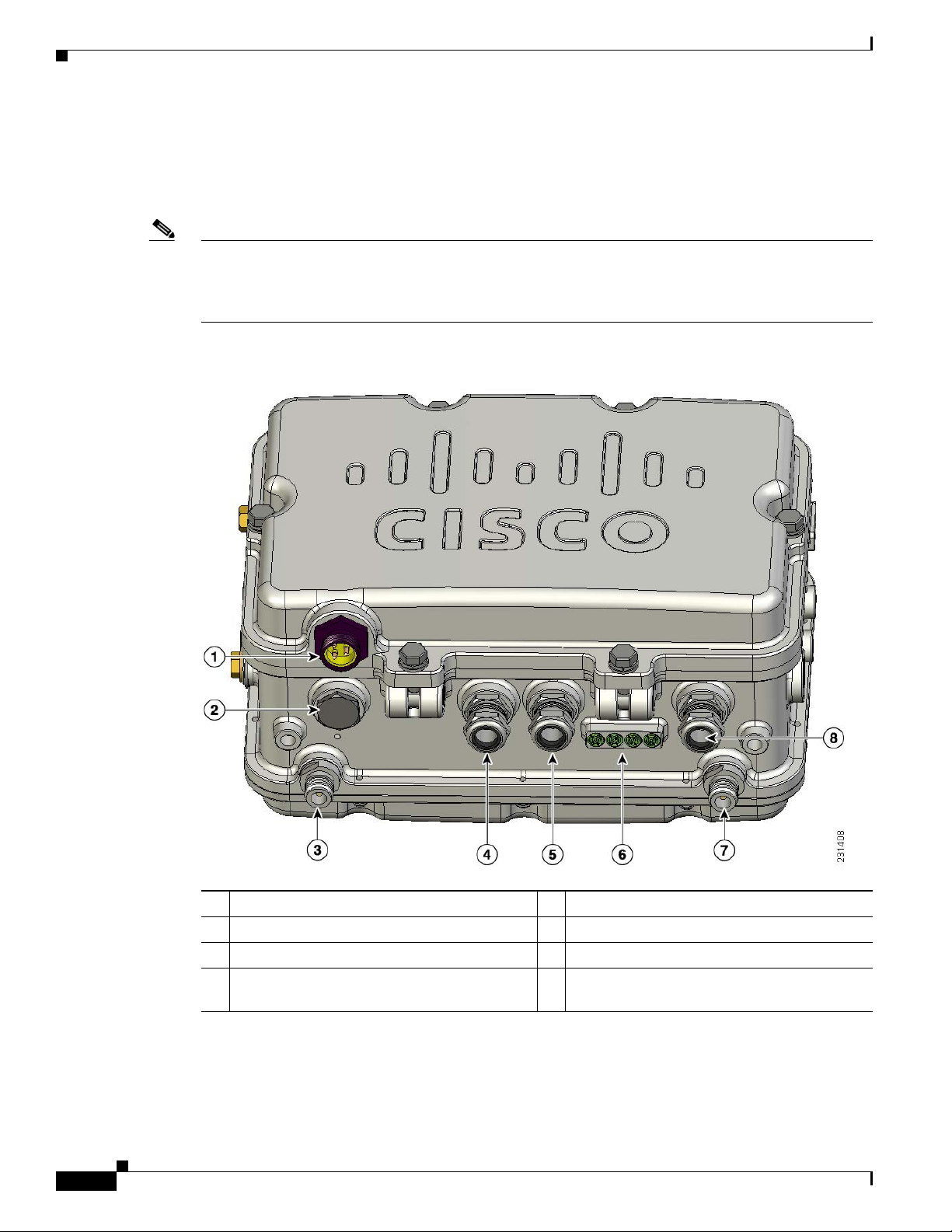
Figure 1-1 Access Point Bottom Connectors
Chapter 1 Overview
1-2
1 AC power c o n n ecto r1 (option al)
5 PoE-Out connector
2 Reserved for future use 6 LEDs
3 Antenna connec tor3 (Type N)
4 Alternate fiber-optic connector location
7 Antenna connector3 (Type N)
8 PoE-In connector
(optional)
1. Only one pow er sour c e is usua ll y co n fig ure d.
2. PoE = Power over Eth ern et
3. Antenna locations depend upon access point configuration (see the “Antenna Connector Locations” section on page 1-5).
Cisco Aironet 1520 Series Outdoor Mesh Access Point Hardware Installation Guide
2
1, 2
OL-12632-02
Page 3
Chapter 1 Overview
Hardware Features
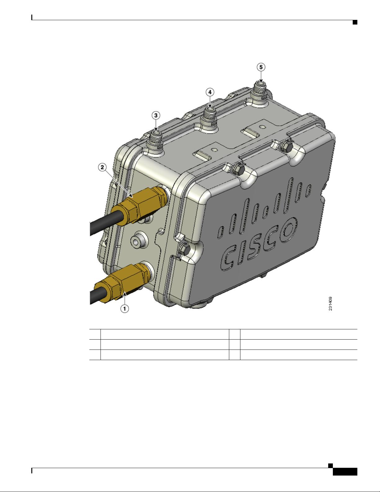
Figure 1-2 Cable, Fiber-Optic, and Antenna Connector Locations
OL-12632-02
1 Cable POC connec tor (o pti onal)
2 Fiber-optic connector3 (optional)
1
4 Antenna connector2 (Type N)
5 Antenna connector2 (Type N)
3 Antenna connec tor2 (Type N)
1. Stinger connector shown is user supplied.
2. Antenna locations depend upon access point configuration (see the “Antenna Connector Locations” section on page 1-5).
3. Liquid tight adapter not shown.
Cisco Aironet 1520 Series Outdoor Mesh Access Point Hardware Installation Guide
1-3
Page 4
Hardware Features
Chapter 1 Overview
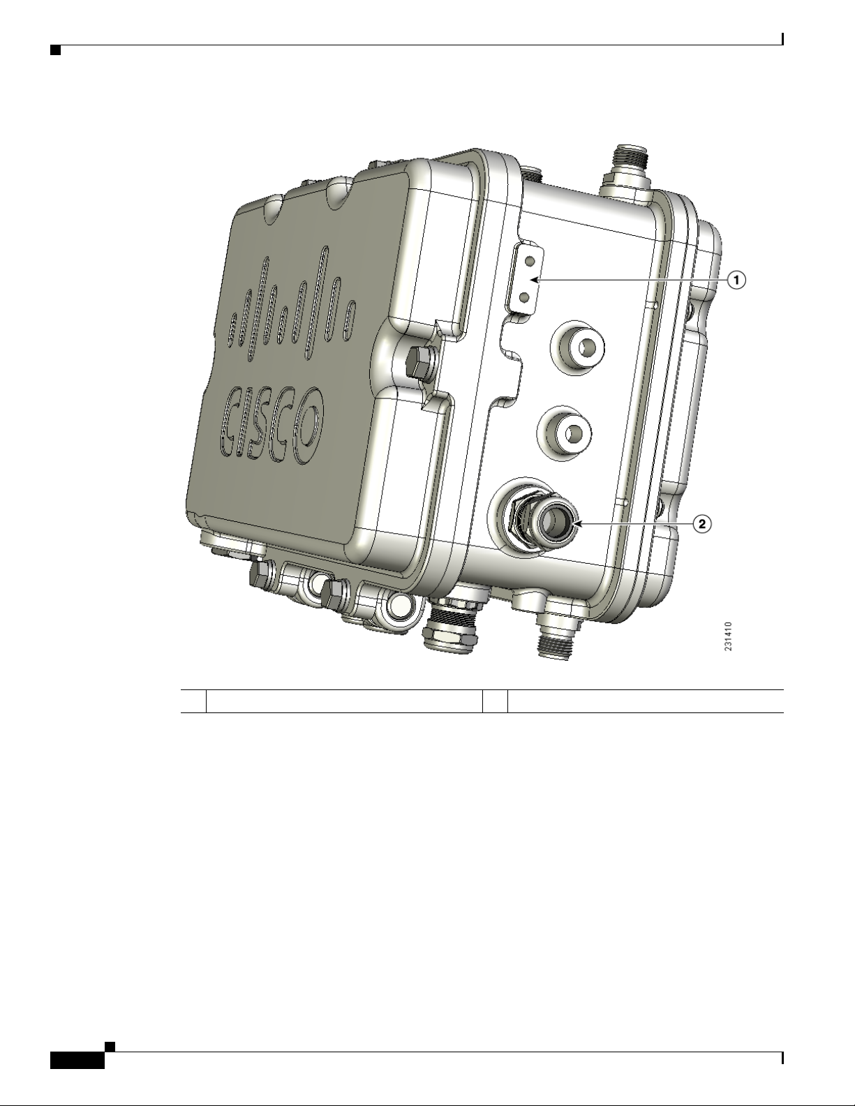
Figure 1-3 DC Power Connector and Ground Screw Holes
1-4
1 Ground screw holes 2 DC power connector
Some of the access point’s hardware features are listed below:
• Two radios (2.4- and 5-GHz)—see t he “Dual Ra dio Operat ion” sect ion on page 1-7
• External radi o anten nas —see the “Ext erna l Ant enna s” se ct ion o n page 1-7
• Multiple power sources—see the “Multiple Power Sources” section on page 1-8
• Ethernet ports —see the “Ethernet Ports” section on page 1-9
• Rugged metal enclosure—see the “Metal Enclosure” sect ion on page 1-10
• Optional cable modem—see the “Cable Modem” se ct ion o n pa ge 1-10
• Optional hardware—see the “Optional Hardware” section on page 1-10
Cisco Aironet 1520 Series Outdoor Mesh Access Point Hardware Installation Guide
OL-12632-02
Page 5

Chapter 1 Overview
Connectors
The optional featur es of the ac cess poin t support the se conne ctors (se e Figure 1- 1):
• PoE-in connector—internal RJ-45 with liquid tight adapter for waterproofing
• PoE-out connector—internal RJ-45 with liquid tight adapter for waterproofing
• Three or four a nten na conn ec tor s ( Type N)—depends o n ac cess poi nt co nfigurat ion
• Fiber-optic connector—internal small form-factor pluggable (SFP) transceiver with LC connector
• Power-over-cable (POC) stinger connector— cu stome r provi ded
• AC power connector (3-pin Remke Mini-Link 5090 8)
• DC power connector— int erna l 2- pin c on ne ctor
Antenna Connector Locations
The access point is ma nufactur ed in thre e configurati ons, ca ble, me sh, and pole mount. Th ese
configurations support sp eci fic locat ions for the ac cess point an tenn as, as shown in
Hardware Features
Table 1-1.
Ta b l e 1-1 Antenna Locations per Access Point Configuration
Antenna
Port
Access Point Configurations
Cable Mesh and Pole Mount
1 2.4-GHz antenna con ne ctor (R X) 5-GHz antenna connector (TX/RX)
2 5-GHz antenna conne ctor (TX /RX) –
3 2.4-GHz antenna con ne ctor
1
2.4-GHz antenn a connec tor (RX)
(TX/RX)
4 –
5 –
6 –
1
1
1
2.4-GHz antenn a connec tor (RX)
1
–
2.4-GHz antenn a connec tor
(TX/RX)
1. Reserved for future use. A plug is installed.
OL-12632-02
Cisco Aironet 1520 Series Outdoor Mesh Access Point Hardware Installation Guide
1-5
Page 6
Hardware Features
Chapter 1 Overview
Figure 1-4 shows the ant enn a por t l ocati on s v iewed from t he hinge d cover side .
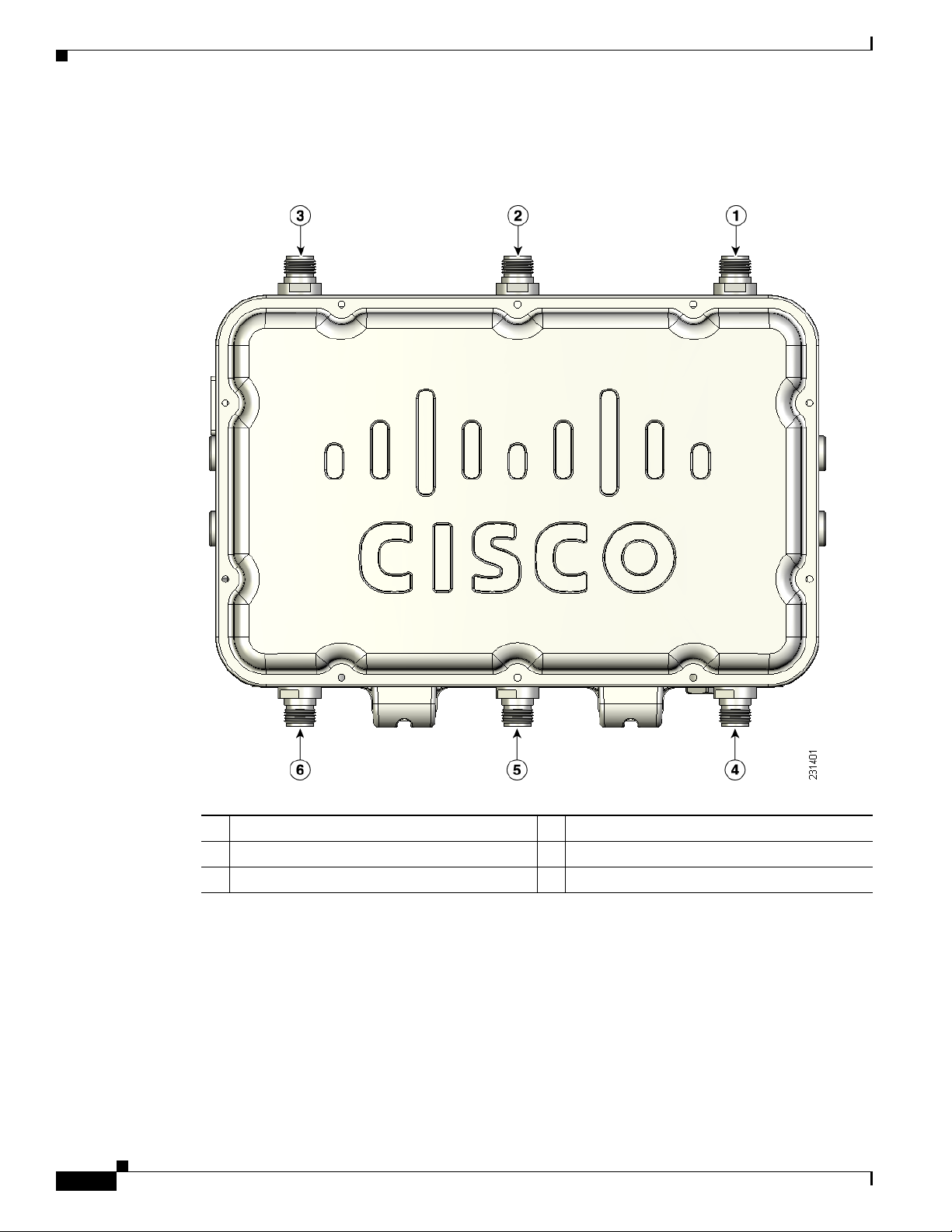
Figure 1-4 Antenna Port Locations
1-6
1 Antenna port 1 4 Antenna port 4
2 Antenna port 2 5 Antenna port 51
3 Antenna port 3 6 Antenna port 6
1. Reserved for future use. A plug is installed.
Cisco Aironet 1520 Series Outdoor Mesh Access Point Hardware Installation Guide
OL-12632-02
Page 7

Chapter 1 Overview
Dual Radio Operation
The access point supports 2.4-GHz and 5-GHz radios using external antennas (see “External Antennas”).
The LAP1522 model supp orts si mul tane ous dual -rad io ope rat ion u si ng a 2. 4-GH z 802 .11 b/g rad io an d
a 5-GHz 802.11a radio.The 5-GHz radio can operate in either the upper industrial, scientific and medical
(ISM) 5.8-GHz b and or the pu bli c saf ety 4. 9-GH z b an d. Th e 5- GHz rad io su ppo rts o ne a nte nna a nd is
used for backhaul operat ions to the co ntrolle r.
Note The 4.9-GHz band requires a license and can only be used by qualified public safety operators as def ined
in section 90.20 of the FCC rules.
The 2.4-GHz radio supports two or three antennas for multi-input, single output (MISO) operation. The
access point uses two o r three recei vers to support maximum rat io combining (MRC) to enhance recei ver
performance. MRC is a technique that combines the signals from multiple receivers in a manner to
optimize the signals. MRC can provide up to 3 dB of increased receive signal strength with two receive
antennas or up to 5 dB with three antennas.
Hardware Features
External Antennas
The access point supports up to three N-type radio frequency (RF) antenna connectors on the top of the
unit and two on the bottom of the unit. The number of active antenna connectors depends upon the access
point configuration (see
supports multiple 2.4 -GHz ante nnas fo r MISO oper ation, but only on e 5-GHz ant enna.
When using the optional Cisco compact omnidirectional antennas, the 2.4- and 5-GHz antennas connect
directly to the access point. The Cisco omnidirectional antennas use vertical polarization.
Warning
Caution For directly mounted antennas, you must not add wea therpr oofing around the antenna conn ector s
Only trained and qualified personnel should be allowed to install, replace, or service this equipment.
Statement 1030
The access point has been designed to operate with the antennas listed below and with a maximum gain
of 8 dBi for 2.4 GHz and 17 dBi for 5 GHz. Antennas not in this list or with a higher gain are strictly
prohibited for use with the a ccess point . The requir ed ante nna impedan ce is 50 ohms.
To reduce potenti al radi o i nte rfere nce to ot her users, the a nte nna ty pe a nd its gai n shoul d be c ho sen so
that the equivalent isotropically radiated power (E.I.R.P.) is not more than required for successful
communication .
because the antenna drain ho les might be b locked and dam age the a ntenna .
Antenna Connector Locations, page 1-5). All access poi nt configur ations
OL-12632-02
Cisco Aironet 1520 Series Outdoor Mesh Access Point Hardware Installation Guide
1-7
Page 8

Hardware Features
Chapter 1 Overview
Table 1-2 and Table 1-3 list the supported externa l a nte nnas for the ac cess point .
Ta b l e 1-2 External 5-GHz Antennas
Part Number Model
AIR-ANT5180V-N 5-GHz compact omnid irecti onal 8
AIR-ANT58G10SSA-N 5-GHz sector 9.5
AIR-ANT5114P-N 5-GHz patch 14
AIR-ANT5117S-N 5-GHz 90-degree sector 17
1. Operation in the 4.9-GHz band requires a license and may be used only by qualified Public Safety operators as defined in
section 90.20 of the FCC rules.
Ta b l e 1-3 External 2.4-GHz Antennas
Part Number Model Gain (dBi)
AIR-ANT2450V-N 2.4-GHz compact omnidir ectiona 5.5
AIR-ANT2480V-N 2.4 GHz omnidirec tio nal 8
Multiple Power Sources
The access point supports these power sources:
• PoE—power injector (AIR -PWRIN J150 0-2=)
• AC power—100 to 480 VAC (standard power source for the pole mount configuration )
1
Gain (dBi)
Warning
Warning
• POC—40 to 90 VAC (quasi-square wave AC), (standard power source for th e c able c onfiguration )
• External 12 VDC
Connect the unit only to DC power source that complies with the safety extra-low voltage (SELV)
requirements in IEC 60950 based safety standards.
• Internal battery
Statement 1033
The access point can be connected to more than one power source. The access point detects the available
power sources and switches to the preferred power source using the following default prioritization:
• AC power or POC power
• External 12-VDC power
• Power injector PoE power
• Internal battery power
This unit might have more than one power supply connection. All connections must be removed to
de-energize the unit.
Statement 1028
1-8
Cisco Aironet 1520 Series Outdoor Mesh Access Point Hardware Installation Guide
OL-12632-02
Page 9

Chapter 1 Overview
Caution To provid e i nli ne PoE , yo u m ust us e t he 1 520 power i nject or (AI R-PW RINJ15 00- 2= ). O the r power
Caution The 1520 power injector (AIR-PWRINJ1500-2=) must be used in an indoo r environment only.
Note In the cable configuration, the cable modem is activated only when the access point is powered by POC
Caution When the access point is installed outdoors or in a wet or damp location, the AC branch circuit that is
Hardware Features
injectors, PoE switches, and 802.3af power sources cannot provide adequate power , which can cause the
access point to malfunction and cause over-current conditions at the power source.
or external 12 VDC p ower. When using only PoE power, the cable mo de m is de activated.
powering the access point should be provided with ground fault protection (GFCI), as required by Article
210 of the National Electrical Code (NEC).
Ethernet Ports
Note The PoE-out port is disabled when the a ccess point is powered by the power injector.
The Ethernet cable from the power injector to the access point (PoE-in port) must be not less than 10 ft
(3.1 m).
The AC power cord options are listed below:
• 40-ft (15.2-m) power cord for light pole installations in the US and Canada. One end of the power
cord is terminated with an ac cess point AC power connector, and the other en d is termi nate d with
an AC plug (AIR-CORD -R 3P-4 0NA=).
• 4-ft (1.2-m) streetlight power tap adapter for light pole installations in the US and Canada
(AIR-PWR-ST-LT-R3P=).
The access point supports a PoE-in port and a PoE-out port. The access point’s PoE-in port uses an RJ-45
connector (with a liquid tight adapter) to link the access point to the 10/100/1000BASE-T network. The
Ethernet cable is used to send and receive Ethernet data and to optionally supply inline 56-VDC power
from the power injector.
The access poin t’s PoE-out (10/10 0/100 0BASE-T) port uses a n RJ-45 co nne cto r (w ith a li qu id ti ght
adapter) to pr ovide L A N c onn ect ivity and IE EE 802 .3a f power to a singl e pe riph er al cu st omer device,
such as a camer a or senso r ga teway. The PoE-out port shoul d not be c on necte d to a swit ch or h ub.
OL-12632-02
Warning
The Ethernet MAC addresses is printed on the bottom of the access point under the LEDs (refer to the
“Finding the Product Serial Number” section on page XIV).
To reduce the risk of fire, use only No. 26 AWG or larger telecommunication line cord.
Cisco Aironet 1520 Series Outdoor Mesh Access Point Hardware Installation Guide
Statement 1023
1-9
Page 10

Hardware Features
Caution To provid e i nli ne PoE , yo u m ust us e t he 1 520 power i nject or (AI R-PW RINJ15 00- 2= ). O the r power
Cable Modem
Note The access point uses a Scientific Atlanta DPC2100 cable modem board and 4015821 RF splitter.
Chapter 1 Overview
The Ethernet cabl e m ust be a shie lde d outdo or rat ed Ca tegory 5e ( CAT5e) or better cable. The a cce ss
point senses the Ethernet and power signals and automatically switches internal circuitry to match the
cable connections.
injectors, PoE switches, and 802.3 af power sources can not provide ad equa te power, which may cause
the access point to malfunction and cause possible over-current conditions at the power source.
The access point cable configuration contains an internal cable modem for connection to the cable
network from the pole-mount ed cabl e lines. Th e acc ess point can be powered using the 40 -to 90-VAC
(quasi-square wave AC) power provided by the cable network.
The cable modem supports these main features:
• Data Over Cable Service Interface Specifications (DOCSIS) 2.0
• Backward compatibility with existing DOCSIS 1.1 and 1.0 networks
Metal Enclosure
The access po int uses a me tal en cl osure th at ca n acco mm oda te bo th in door or o utdoo r ope rat ing
environments and an industria l tem pera ture op erat ing ra nge of –40 to 13 1°F (– 40 to 55°C ). The a cce ss
point complies with NEM A 4 and IP67 requ ireme nts.
Optional Hardware
Some of the access point hardware options are listed below:
• Fiber-optic module and t ake-up ree l kit (GL C- FE- 100BX -URG D=) —Sma ll for m- factor p lugga ble
(SFP) module for connection to fiber-optic lines. The take-up reels are used to store excess
fiber-optic cable by wrapping the c able ar ound the re els.
–
–
–
Single strand fiber bidirectional opti cal tra nsceiver
1.3 (transmit) /1. 5 ( rec eive) microm ete r wavelength division mu ltip lexing ( WD M) f unc tion
100 Mb/s data rates
1-10
–
LC receptacle
–
Supports up to 15.5 mi (25 km) of fiber-optic cable.
• Pole mount kit (AIR-ACCPMK15 20=)—provides hardware for mounting the access point to a metal
or wood pole, su ch a s a stre etl ight pol e.
• Strand mount kit (A I R-ACCSMK1520=)— provide s har dware fo r mou nting t he a ccess p oi nt to a
cable strand.
Cisco Aironet 1520 Series Outdoor Mesh Access Point Hardware Installation Guide
OL-12632-02
Page 11

Chapter 1 Overview
• Streetlight power tap ad apter (AIR-PWR-ST-LT-R3P=)—connects to the light control connector on
a streetlight pole and provides AC power to the access point.
• 1520 power injecto r (AIR-PWRINJ1500-2=)—provides PoE to the access point.
• 40-ft (12.2-m) power cord for light pole installations in the US and Canada
(AIR-CORD-R3P-40NA=)—provides AC power to the access point. One end of the power cord is
terminated with an access point AC power connector, and the other end is terminated with an AC
plug.
• Battery backup m odu le (AIR- 152 0-BATT-6AH). The integrate d b att ery can be us ed for t empor ar y
backup power during external power interr uption s.
–
3- hour access po in t op er ati on us ing two ra dio s a t 77oF (25oC)—with PoE output port off
–
2-hour access point operation usi ng two radios at 77oF (25oC)— with PoE outpu t po rt on
• Strap hand tool (AIR-BAND-INST-TL=)—used to install the metal straps used in pole mounting.
Network Deployment Examples
The access poin t is a wir eless d evice desi gned fo r wir eless c lien t a cce ss and po int -to-p oint bri dgin g,
point-to-multipoint bridging, and point-t o-multi point mesh w ireless con nectivity. The access point
provides 5-GHz back ha ul c apab ilit y to li nk wi th a not her ac cess point to r eac h a wir ed ne twork
connection or to provide repeat er operat ions for other access points.
Network Deployment Examples
The access point plays one of two primary radio roles: a root access point (hereafter called a RAP) or the
access points that relay their wireless connections to the controller are called mesh access points
(MAPs). When the access point has a wired Ethernet, fiber-optic, or cable connection to the controller
(through a switch), th e ra dio role is ca lled a RAP. A RAP is a parent node to any br idgi ng or m e sh
network. A controller can support one or more RAPs, each one parenting the same or different wireless
networks. There can be more th an one RAP fo r the same m esh ne twork f or re dun dancy. Both RAP and
MAP access points can su pport wi reless clie nts using the 2.4- GHz rad io.
Note The access point must be configured as a RAP in the controller, whereas the MAP role is a default
setting.
When the access point does not hav e a wired Ethernet, fiber-optic, or cable connection to the controller,
the radio role is called a MA P. The MAPs have a wireless connecti on (throug h the back haul int erface )
to other MAPs and finally to a RAP with an Ethernet or cable connection through a switch to the
controller. MAPs can also have a wired Ethernet connect ion to a lo cal LAN and serve as a bridg e
endpoint for t hat LAN (usi ng a p oin t-to- poin t or po i nt-to- mul tipoi n t br idge conn ec ti on).
OL-12632-02
Cisco Aironet 1520 Series Outdoor Mesh Access Point Hardware Installation Guide
1-11
Page 12
Network Deployment Examples
(2.4 Ghz)
148440
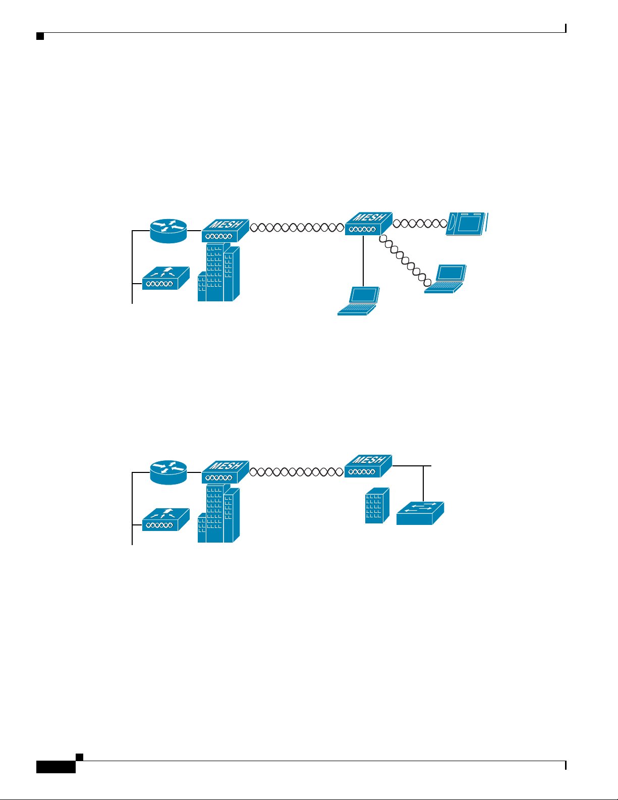
Wireless Backhaul
The access point supports wireless backhaul capability using the 5-GHz radio to bridge to another access
point to reach a wired net work conne ction to a contro ller (see
to the wired network is considered a RAP in this configuration. The remote access point is considered a
MAP and transfers wireless client traffic to the RAP for transfer to the wired network. Lightweight
access point prot ocol (LWAPP) cont rol tr affic is also tra nsf erre d over thi s bridg ed link .
Figure 1-5 Access Point Backhaul Example
Chapter 1 Overview
Figure 1-5). The access point connected
(5.8 Ghz)
148438
Point-to-Point Bridging
The access points can be used to extend a remote n et work by using the 5-GHz backhaul radio to bridge
the two network segments as shown in
bridging on the controller for each acc ess point.
Figure 1-6 Access Point Point-to-Point Bridging Example
Figure 1-6. To suppor t E the rnet b ridging , you must ena ble
1-12
Cisco Aironet 1520 Series Outdoor Mesh Access Point Hardware Installation Guide
OL-12632-02
Page 13
Chapter 1 Overview
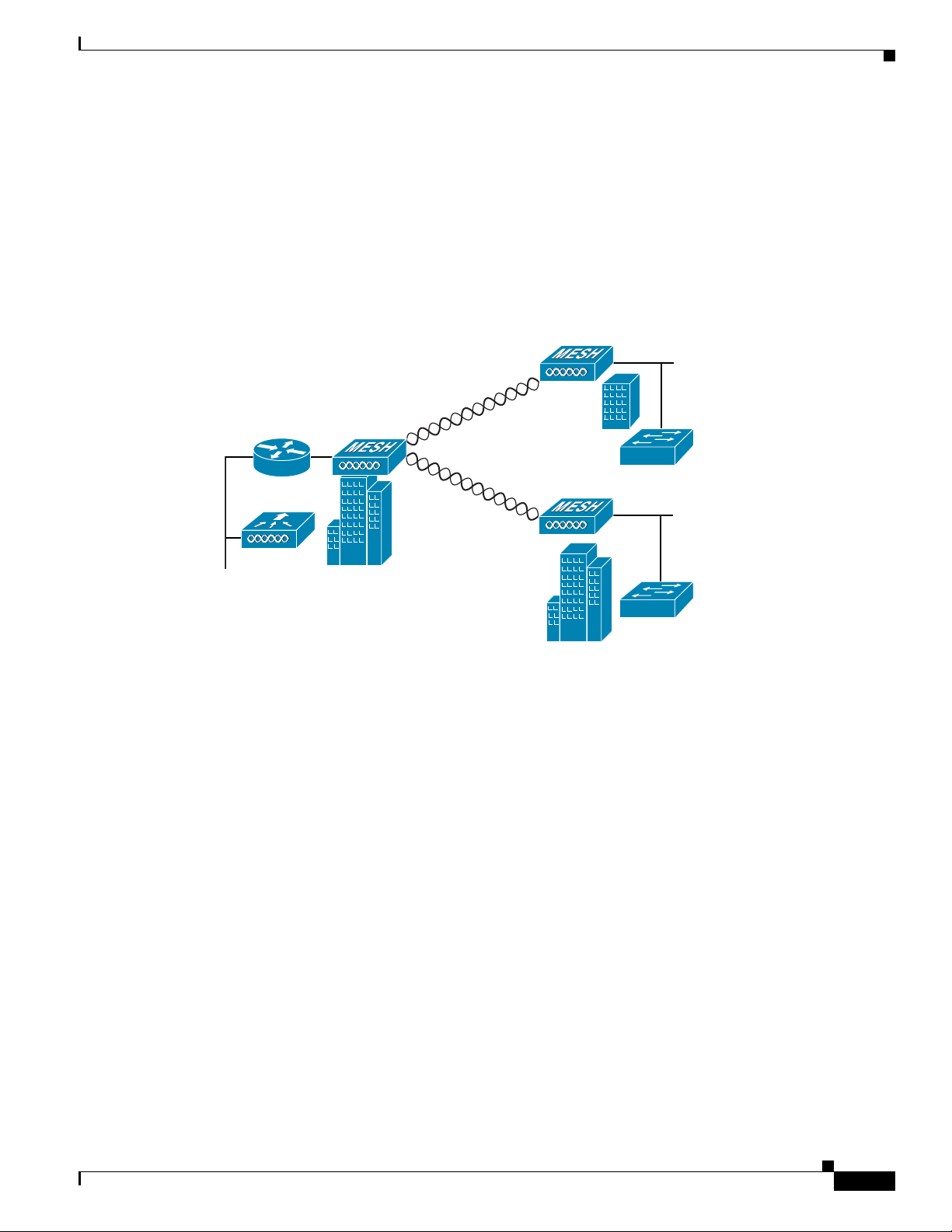
Point-to-Multipoint Bridging
The access points can be used as a RAP to connect multiple remote MAPs with their associated wired
networks (see
Ethernet bridging, you mu st enable br idging on the controller for each acc ess point.
Wireless client access can be provided over the bridging link; however, if bridging between tall
buildings, the 2.4-GHz w irele ss coverage are a m ight b e li mited and pos sibl y n ot su itable f or di rec t
wireless client access.
Figure 1-7 Access Point Point to Multipoint Bridging Example
Figure 1-7). By default, this capability is turned-off for all access points. To support
Network Deployment Examples
148439
OL-12632-02
Cisco Aironet 1520 Series Outdoor Mesh Access Point Hardware Installation Guide
1-13
Page 14
Network Deployment Examples
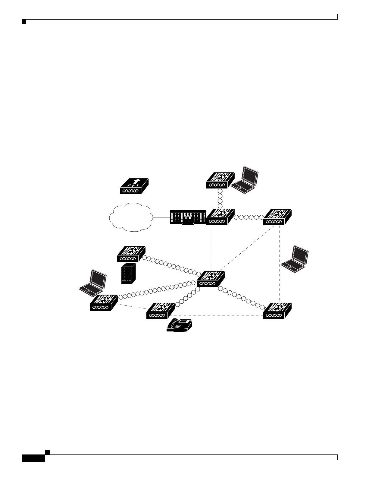
Mesh Network
Chapter 1 Overview
The access points are typically deployed in a mesh network configuration. In a typical mesh deployment,
one or more RAPs have a wired network connection through a switch to a controller. Other remote MAPs
without wired network connections use the backhaul feature to optimally link to a RAP that is connected
to the wired network. In the mesh network, the links between the access points are referred to as the
backhaul links.
Intelligent wireless routing is provided by the patented Adaptive Wireless Path Protocol (AWPP). This
enables each MAP to identify its neighbors and intelligently choose the optimal path to the RAP with
the wired network co nnec tio n by c alcul at ing the co st of e ach pat h in t erm s o f sig na l stre ngth a nd the
number of hops required to get to a controll er.
Figure 1-8 illustrates a typical mesh configuration using MAPs and RAPs.
Figure 1-8 Typical Mesh Configuration Using Access Points
1-14
IP
Cisco Aironet 1520 Series Outdoor Mesh Access Point Hardware Installation Guide
155631
OL-12632-02
Page 15
Chapter 1 Overview
158085
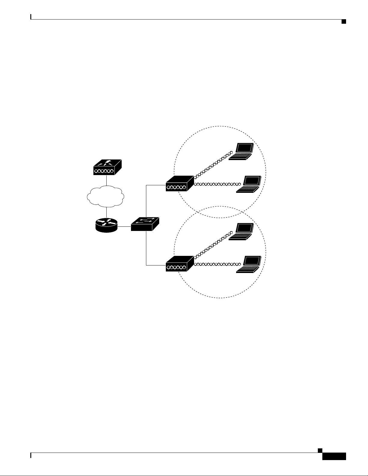
Layer 3 Network Operation
The access poin ts su ppor t L ay er 3 ne twork ope ratio n. A ccess p oi nts a nd cont r oller s in La yer 3
configurations use IP addresses and UDP packets, which can be routed through large networks. Layer 3
operation is scalable and recommended by Cisco.
Figure 1-9 illustrates a typical Layer-3 wireless network configuration containing access points and a
controller.
Figure 1-9 Typical Layer 3 Access Point Network Configuration Example
Network Deployment Examples
LWAPP
LWAPP
OL-12632-02
Cisco Aironet 1520 Series Outdoor Mesh Access Point Hardware Installation Guide
1-15
Page 16

Network Deployment Examples
Chapter 1 Overview
1-16
Cisco Aironet 1520 Series Outdoor Mesh Access Point Hardware Installation Guide
OL-12632-02
Page 17

CHA PT ER
2
Mounting Instructions
This chapter describes warnings, safety information, and mounting information needed during the
installation of your ac cess point . The chap ter co ntains these secti ons:
• Unpacking the Access Po int, page 2-2
• Tools and Materials that You Supply, pa ge 2-2
• Warnings, page 2-4
• Safety Informa tion, p ag e 2-4
• Avoiding Damage to Radios in a Testing Environment, page 2-7
• Installation Guidelines, page 2-8
• Mounting the Access Point, page 2-16
• Grounding the Access Point , pa ge 2-42
• Connecting a Fiber-Optic Cable to the Access Point, page 2-43
• Powering the Access Point, page 2-46
OL-12632-02
Cisco Aironet 1520 Series Outdoor Mesh Access Point Hardware Installation Guide
2-1
Page 18

Unpacking the Access Point
Unpacking the Access Point
When you are unpacking the access point, do not remove the foam blocks attached to the antenna
connectors. The foam protects the antenna connectors during installation.
Follow these steps to unpack the access point:
Step 1 Open the shipping container and carefully remove the contents.
Step 2 Return all pack i ng ma ter ials t o t he sh i pping cont ai ner, and save it.
Step 3 Ensure that all items listed in Package Contents are included in the shipment. If any item is damaged or
missing, notify your authori zed Cisco sales repr esenta tive.
Package Contents
Each access point pack age co ntain s the foll owing items:
• Access point
Chapter 2 Mounting Instructions
• Cisco product documentat ion and tran slated safe ty warnings
• Grounding lug wit h two screws and loc k washe rs
• Three liquid tight adapters
• Two-pin DC power connector
• Ground lug (Panduit PLCD6-10A -L) and screws with loc k washers
Tools and Materials that You Supply
• Ground lug crimping too l (Panduit CT-720 with CD-720-1 die)
• 6-AWG copper ground wire
• 13 mm box-end w r en ch or so cket set
• Adjustable wrench, 22 mm socket, or Sealcon S-2200-WR socket wrench
• Small flat screwdriver for DC power co nnec tor
• Optional power injector ( AIR- PWR INJ1 500 -2=)
• Optional AC power cord
–
40-ft (12.2-m) power cord (AIR-CORD-R3P-40NA=) for light pole installations in the US and
Canada
–
4-ft (1.2-m) streetli ght power tap adap ter (AIR -PWR-ST-LT-R3P=) for light pole installations
in the US and Canada
• Antennas, 2.4 and 5 GHz (refe r to the “ External Antennas ” sec tion on page 1-7)
2-2
• Optional pole mount kit (AIR-ACCPMK1520=)
• Optional strand moun t ki t ( AIR- ACCSMK1520=)
• Optional strap hand tool (AIR -BAND-INST-TL=)
Cisco Aironet 1520 Series Outdoor Mesh Access Point Hardware Installation Guide
OL-12632-02
Page 19

Chapter 2 Mounting Instructions
• Optional fiber-optic 100BASE-BX10-U SFP, fiber-optic take-up reels, and liquid tigh t a dapt er
• Optional outdoor-rated fiber-optic cab le with 0. 20 to 0 .35 in. (0. 51 to 0 .89 cm) d iame te r
• Optional shielded outdo or-rate d Et herne t ( CAT5e or better) cable with 0. 20 to 0.3 5 in
• Optional Ethernet RJ-45 connec tor and in stalla tion tool
• Optional shielde d outdo or-rate d DC power ca ble w ith 0.2 0 t o 0. 35 in. ( .0.51 t o 0.89 c m ) d iam ete r
• Optional cable Stinger connector
• Optional ground rod, as requi red by local regula tions
• Optional ladder, power lift, rop e, o r o the r to ol s as r e quire d
Pole Installation
To install the access point on a vertical or horizon tal metal , wood, or fiberglass pole, you need the
following additional ma teria l a nd t ools:
Tools and Materials that You Supply
(GLC-FE-100BX-U R GD= )
(0.51 to 0.89 cm) diame ter
• Pole mount kit (AIR-ACCPMK1520= )
–
Pole clamp bracket
–
Two gusset strap brackets
–
One mounting b racket
–
Twelve hex bolts (M8 x 16)
–
One M8 flange nut
–
Six M8 flat washers
–
Ten M8 split lock washers
–
Two stainless steel mounting st raps
• Cust o me r su pp l ie d me t al s tr a p tool—(AIR-BAND-IT-TOOL=)
• Customer supplied 13-mm and box -end wrenc h or socket set
• Customer supplied adju stable wr ench , 22 mm socket, or Sealcon S-2200-WR socket wren ch
Cable Strand Installation
To install the access poin t on a cable stra nd, you need the following ad ditiona l parts:
• Cable strand mount kit (AIR-ACCSMK1520= )
–
Strand mounting bracket
–
Strand clamp bracket
OL-12632-02
–
Four cable clamps
–
Four M8 flange n uts
–
Four hex bolts (M8 x16)
–
Four M8 split lock washers and six M8 flat washe rs
• Customer supplied 13-mm box-end wrench or socket set
Cisco Aironet 1520 Series Outdoor Mesh Access Point Hardware Installation Guide
2-3
Page 20

Warnings
Warnings
Chapter 2 Mounting Instructions
• Customer supplied adju stable wr ench , 22 mm socket, or Sealcon S-2200-WR socket wren ch
Translated v ersions of all safety wa rnings are a vailable in the safety warning document that shipped with
your access poin t or on Cisc o.co m. To browse to the documen t on Cisc o. co m, re fer to
“Translated Safety Warnings” for instructions.
Appendix A,
Warning
Warning
Warning
Warning
Warning
IMPORTANT SAFETY INSTRUCTIONS
This warning symbol means danger. You are in a situation that could cause bodily injury. Before you
work on any equipment, be aware of the hazards involved with electrical circuitry and be familiar
with standard practices for preventing accidents. Use the statement number provided at the end of
each warning to locate its translation in the translated safety warnings that accompanied this device.
Statement 1071
SAVE THESE INSTRUCTIONS
Do not operate the unit near unshielded blasting caps or in an explosive environment unless the
device has been modified to be especially qualified for such use.
This equipment must be externally grounded using a customer-supplied ground wire before power is
applied. Contact the appropriate electrical inspection authority or an electrician if you are uncertain
that suitable grounding is available.
Read the installation instructions before connecting the system to the power source.
Ultimate disposal of this product should be handled according to all national laws and regulations.
Statement 1040
Statement 364
Statement 366
Statement 1004
Safety Information
Follow the guidelines in this section to ensure proper operation and safe use of the access point.
FCC Safety Compliance Statement
The FCC, with its action in ET Doc ket 96-8, has adop ted a safe ty standard for human exposur e to RF
electromagnetic energy emitted by FCC-certified equipment. When used with approved Cisco Aironet
antennas, Cisco Aironet products meet the uncontrolled en vironmental limits found in OET-65 and ANSI
C95.1, 1991. Proper operation of this radio device according to the instructions in this publication results
in user exposure substantially below the FCC recommended limits.
Cisco Aironet 1520 Series Outdoor Mesh Access Point Hardware Installation Guide
2-4
OL-12632-02
Page 21

Chapter 2 Mounting Instructions
Safety Precautions
Safety Information
Warning
Warning
Warning
Warning
Warning
Warning
In order to comply with radio frequency (RF) exposure limits, the antennas for this product should be
positioned no less than 6.56 ft (2 m) from your body or nearby persons.
The AC power supply has double pole/neutral fusing.
Statement 188
Statement 339
Do not work on the system or connect or disconnect cables during periods of lightning activity.
Statement 1001
Class 1 laser product.
Statement 1008
There is the danger of explosion if the battery is replaced incorrectly. Replace the battery only with
the same or equivalent type recommended by the manufacturer. Dispose of used batteries according
to the manufacturer’s instructions.
A readily accessible two-poled disconnect device must be incorporated in the fixed wiring.
Statement 1015
Statement 1022
Warning
Warning
Warning
Warning
Warning
To reduce the risk of fire, use only No. 26 AWG or larger telecommunication line cord.
Statement 1023
This unit might have more than one power supply connection. All connections must be removed to
de-energize the unit.
Statement 1028
Only trained and qualified personnel should be allowed to install, replace, or service this equipment.
Statement 1030
Connect the unit only to DC power source that complies with the safety extra-low voltage (SELV)
requirements in IEC 60950 based safety standards.
Statement 1033
When installing or replacing the unit, the ground connection must always be made first and
disconnected last.
Statement 1046.
OL-12632-02
Cisco Aironet 1520 Series Outdoor Mesh Access Point Hardware Installation Guide
2-5
Page 22

Safety Information
Chapter 2 Mounting Instructions
Warning
Do not locate the antenna near overhead power lines or other electric light or power circuits, or
where it can come into contact with such circuits. When installing the antenna, take extreme care
not to come into contact with such circuits, because they may cause serious injury or death. For
proper installation and grounding of the antenna, please refer to national and local codes (for
example, U.S.:NFPA 70, National Electrical Code, Article 810, Canada: Canadian Electrical Code,
Section 54).
Caution Before connecting or disconnecting a power cord, you must remove AC power from the power cord using
Statement 1052
a suitable servic e disconn ect .
For additional importa nt safety instructions for AC power cords, refer to the AC Power Cords for Cisco
Aironet 1520 Series Outdoor Mesh Access Points document that shipped with you r AC power cords.
For safety and to achieve a good installation, please read and follow these safety precautions:
1. Select your installation site with safety, as well as performance in mind. Remember: electric power
lines and phone lines look alike. For safety, assume that any overhead line can kill.
2. Call your electric power company. T ell them your plans, and ask them to come look at your proposed
installation.
3. Plan your installa tio n ca re fully a nd co mp let ely befo re you begin. Suc cessf ul r aisi ng of a m ast or
tower is largely a matter of coordination. Each person sh ould be assign ed to a specific tas k and
should know what to do and when to do it. One person should be in charge of the operation to issue
instructions and watc h for sign s o f troub le.
4. When installing the access point and antennas, remember:
a. Do not use a metal lad de r.
b. Do not work on a w et or w indy da y.
c. Do dress properly—shoes with rubber soles and heels, rubber gloves, long sleeved shirt or
jacket.
5. Use a rope to lift the access point. If the assembly starts to drop, get away from it and let it fall.
6. If any part of the antenna syst em sh oul d com e in c onta ct wi th a p ower line, do no t tou ch it or try t o
remove it yourself. Call your local power company. They will remove it safely.
If an accident should occur, call for qualified emergency help immediately.
2-6
Cisco Aironet 1520 Series Outdoor Mesh Access Point Hardware Installation Guide
OL-12632-02
Page 23

Chapter 2 Mounting Instructions
Avoiding Damage to Radios in a Testing Environment
Avoiding Damage to Radios in a Testing Environment
The radios on outdoor units (bridges) have higher transmit power levels than radios on indo or units
(access points). When you t est high power radios in a lin k, you must avoid exceeding the rec eiver’s
maximum receive input level. At levels above the normal operatin g range, pa cket erro r rate (P ER)
performance is degraded. At even higher levels, the receiver can be permanently damaged. To avoid
receiver damage and PER degrada ti on, you ca n use o ne of t he fol lowing t echn ique s:
• Separate the omnidirectional antennas by at least 2 ft (0.6 m) to avoid receiver damage or by at least
25 ft (7.6 m) to avoid PER degradation.
Note These distance s assum e fre e space path loss and ar e cons ervative estimate s. Requi red
separation distances for damage and performance degradation levels in actual deployments are less if
conditions are not non line-of-sight.
• Reduce the configured transmit power to the minimum level.
• Use directional antennas, and keep them away from each other.
• Cable the radios together using a co mbination of attenuators, c ombiners, or splitters to achie ve a total
attenuation of at least 60 dB.
For a radiated test bed, the foll owing equation descr ibes the relationships among transmit po wer , antenna
gain, attenuation, and receiver sensitivity:
txpwr + tx gain + rx gain - [attenuation due to antenna spacing] < max rx input level
Where:
txpwr = Radio transmit power level
tx gain = transmitter antenna gain
rx gain = receiver antenna gain
For a conducted test bed, the fol lowing equation describes th e relations hips am ong transm it power,
antenna gain, and rec eiver sensitivity:
txpwr - [attenuation due to coaxial components] < max rx input level
Caution Under no circumstances should you con nec t t he ant enna por t from one ac cess po int to the ant enna port
of another access po int wi thou t using a n RF att enua tor. If you connec t a ntenna ports, y ou mu st no t
exceed the maximum survivable receive level of 0 dBm. Never exceed 0 dBm, or damage to the access
point can occur . Using attenuato rs, combiners, and splitters hav ing a total of at least 60 dB of att enuation
ensures that the receiver is not damaged and th at PER perf orma nce is not degrade d.
OL-12632-02
Cisco Aironet 1520 Series Outdoor Mesh Access Point Hardware Installation Guide
2-7
Page 24

Installation Guidelines
Installation Guidelines
Because the access point is a radio device, it is susceptible to common causes of interference that can
reduce throughpu t a nd ra nge . Foll ow these b asic gu ide lin es t o ensu re the b es t pos sibl e perfo rm an ce:
• For information on planning and initially configuring your Cisco Mesh network, refer to the
Deployment Guid e: Ci sco Mes h N etw or king So lut ion.
• Perform a site survey before beginning the inst allat ion.
• Install the access point in an area where structures, trees, or h ills do not obstruct rad io signals to and
from the access point.
• The access points can be installed at any height, but best throughput is achieved when all the access
points are mount ed at the same hei ght. We recommends installi ng the a cce ss p oints no high er tha n
40 feet to allow support for wireless clie nts on the gro und.
Note To calculate path loss and to determine how far apart to install access points, consult an RF planning
expert.
Chapter 2 Mounting Instructions
Site Surveys
Every network application is a unique installation. Before installing multiple access points, you should
perform a site survey to determine the optimum use of networking components and to maxi mize range,
coverage, and network p erfor ma nce.
Consider the following operating and environmental conditions when performing a site survey:
• Data rates—Sensitivity and range are inversely proportiona l to data bit rat es. The ma ximum ra dio
range is achieved at the lowest workable data rate. A decrease in receiver sensitivity occurs as the
radio data increases.
• Antenna type and placement—Proper antenna configuration is a critical factor in maximizing radio
range. As a general ru le, ra nge in cr ease s in p rop ortio n to an te nna he ig ht. Howev er, do not place the
antenna higher than necessary, because the extra height also increases potential interference from
other unlicensed rad io sy stem s a nd de cr ease s th e wir eless c overage f rom t h e gro und .
• Physical environment—Clear or op en are as pr ovide b ett er r ad io r an ge t han cl os ed or filled ar e as.
• Obstructions—Physical obstructions such as buildings, trees, or hills can hinder performance of
wireless devices. Avoid locating the dev ices i n a locatio n wher e th er e is a n obs truct ion b etwe en th e
sending and receiving ante nnas.
2-8
Cisco Aironet 1520 Series Outdoor Mesh Access Point Hardware Installation Guide
OL-12632-02
Page 25

Chapter 2 Mounting Instructions
Before Beginning the Installation
Before you begin the installation process:
• Ensure that a site survey has been perfo rmed .
• Ensure that your network i nfrastr ucture devices are opera tiona l and prope rly co nfigured.
• Ensure that your cont rollers ar e conne cted to s witch trunk ports.
• Ensure that your switch is configured with untagged access ports for connecting your access points.
• Ensure that a DHCP server with Option 43 configured is reac hable by your acc ess points , or
manually configure the controller information in the access point (for additional information, refer
to the
“Configuring DHCP Option 43” section on pa ge F-1).
• Become familiar with the access point installation components (see the “Becoming Familiar with
Access Point Installation Components” section on page 2-9).
Becoming Familiar with Access Point Installation Components
The access point is designed to be installed in an indoor or outdoor environment, such as an interior wall
or ceiling or the exterior roof overhang of a tall building or a streetlight pole. Carefully review the
following f igures to be come familiar with the system compone nts, connectors , indicators, cables, system
interconnection, and gro unding:
Installation Guidelines
• Components in a typical access point installation (see Figure 2-1)
• Pole mount installa tion ( se e Figure 2-2)
• Cable strand mount install ation (se e Figure 2-3 )
• Streetlight power tap installation (see Figure 2-4)
Note The illustrations in this document show all available connections for the access point. Unused
connections are capped with a connector plug to ensure the access point’s watertight integrity. liquid
tight adapters are provided for connector openings, which can be install ed before or after deploying the
access point. The illustrations do not show antenna port 5, which is reserved for future use.
OL-12632-02
Cisco Aironet 1520 Series Outdoor Mesh Access Point Hardware Installation Guide
2-9
Page 26

Installation Guidelines
231523
Chapter 2 Mounting Instructions
Figure 2-1 Components in a Typical Access Point Installation
1
2
10 8
9
3
7
4
5
6
1 Building roof-overhang 6 Ground
2 Shielded outdoor-rated Et hern et
(CAT5e or better) cable
1
7 AC power cord
3 Water drip loop 8 Power injector
6-AWG copper grou ndi ng wi re1 9 Shielded Ethernet (CAT5e or better) cable
2
3
1
5 Ground rod1 10 Controller (throu gh a switch)
1. User supplied.
2. The safety ground wire in the AC power cord must have a ground path to a grounding rod.
3. The shielded Ethernet cable has a ground path through the power injector and the safety ground wire in the AC power cord.
2-10
Warning
Cisco Aironet 1520 Series Outdoor Mesh Access Point Hardware Installation Guide
Installation of the equipment must comply with local and national electrical codes.
Statement 1074
OL-12632-02
Page 27

Chapter 2 Mounting Instructions
Figure 2-2 Pole Mount Installation
Installation Guidelines
OL-12632-02
1 Stainless steel mounting straps
4 2.4-GHz antennas
(part of pole mount kit)
2 2.4-GHz antenna
3 5-GHz antenna
1. Illustration shows antennas for an access point with two radios.
1
1
Cisco Aironet 1520 Series Outdoor Mesh Access Point Hardware Installation Guide
5 Pole (wood, metal, or fiberglass)
6 Mounting bracket ( part o f pol e m oun t ki t)
1
2 to 16 in. (5.1 t o 40. 6 cm ) dia meter
2-11
Page 28

Installation Guidelines
Chapter 2 Mounting Instructions
Figure 2-3 Cable Strand Mounting
2-12
1 Clamp bra cket w ith c ab le cl am p s
5 Cable bundle
(part of strand mount kit)
2 5-GHz antenna
3 2.4-GHz antennas
1
1
6 Fiber-optic connection
7 Cable POC power input
4 Strand support cabl e 8 Strand mount bracket
1. Illustration shows antennas for an access point with two radios.
2. Liquid tight connector not shown.
3. Stinger connector shown is user supplied.
Cisco Aironet 1520 Series Outdoor Mesh Access Point Hardware Installation Guide
2
3
(part of strand mount kit)
OL-12632-02
Page 29

Chapter 2 Mounting Instructions
231524
Figure 2-4 Streetlight Power Tap Adapter Installation
Installation Guidelines
1
1 Outdoor light co ntro l 3 6-AWG copper grou nding wi re
2 Streetlight power tap adapter
Antenna Connector Locations
The access point is ma nufactur ed in thre e configurat ions , cable , pole moun t, and mes h. These
configurations support sp eci fic locat ions for the ac cess point an tenn as as shown in
Ta b l e 2-1 Antenna Locations for Each Access Point Configuration
2
3
Table 2-1.
1
Antenna
Port
Access Point Configurations
Cable Pole Mount and Mesh
1 2.4-GHz antenna conn ec tor (R X) 5-GHz antenna connector (TX/RX)
2 5-GHz antenna connector (TX/RX) –
2
3 2.4-GHz antenna conn ec tor (TX /RX ) 2.4-GHz antenna c onnec to r ( RX )
4 –
5 –
6 –
1. Antenna locations specified for a two radio access point.
2. Reserved for future use. A plug is installed.
2
2
1
2.4-GHz antenna c onnec to r ( RX )
2
–
2.4-GHz antenna conn ec tor (TX /RX )
OL-12632-02
Cisco Aironet 1520 Series Outdoor Mesh Access Point Hardware Installation Guide
2-13
Page 30

Installation Guidelines
Chapter 2 Mounting Instructions
Figure 2-5 shows the ant enn a por t l ocati on s v iewed from t he hinge d cover side .
Figure 2-5 Antenna Port Locations
Adding the Access Point MAC Addresses to the Controller Filter List
Before installing your acc ess points , configure you r controll er by adding the M AC addresses of the
access points to the fil ter list. MAC address filter ing is enabled by def ault. This enab les the co ntrolle r to
respond to the listed access points. Follow these steps to add a MAC filter entry on the controller:
Step 1 Log into y our cont rol ler usin g a w eb browser.
Step 2 Choose SECURITY > MAC Filtering > New.
Step 3 Enter the MAC address of the access point to the MAC Filter list; for example, 00:0B:91:21:3A:C7.
Note The access point MAC address is located on the bottom of the unit. When two MAC addresses
are shown, use the top MAC address.
Cisco Aironet 1520 Series Outdoor Mesh Access Point Hardware Installation Guide
2-14
OL-12632-02
Page 31

Chapter 2 Mounting Instructions
Step 4 Select a WLAN ID or Any WLAN from the WLAN ID pop-up menu.
Step 5 Enter a description (32 characters maximum) of the access point in the Description field; for example,
Fisher_Street_00.0B.91.21.3A.C7 shows the locati on and MAC addre ss of th e acc ess po int.
Step 6 Choose an interface from the Interface Name pop-up menu, and click Apply.
Step 7 Repeat Steps 2 to 6 to add othe r access points to th e list.
Step 8 Log out o f you r c on troll er, and close y our w eb b rowser.
Configuring a RAP
The access point defaults to the MAP radio role. One or more of your access points must be reconfigured
as a RAP. The RAPs connect to a wired Ethernet link through a switch to the controller. The MAPs use
their wireless backhaul interface to connect to a RAP to reach the controller.
Follow these steps to configure a RAP on the controller GU I:
Installation Guidelines
Step 1 Log into y our cont rol ler usin g a w eb browser.
Step 2 Click Wireless. When your access point associates to the controller, your access point’s name appears
in the AP Name list.
Step 3 Double-click yo ur a ccess po int ’s name.
Step 4 Find Mesh Informa tion, and c hoose Ro ot A P by clicking th e drop down arrow in the AP Role field.
Step 5 Click Apply.
Step 6 Repeat Steps 2 through 5 for each RAP.
Step 7 Log out from your controller, and close your web browser.
Configuring a Bridge Group Name
The bridge group name (BGN) controls the association of the access points to a RAP. BGNs can be used
to logically group the radios to avoid different networks on the same channel from communicating with
each other. This setting is al so use ful i f you have more tha n on e R AP in yo ur n etwork i n the s am e are a.
If you have two RAPs in you r network i n th e sam e a rea (f or mo re cap aci ty), we r ecom me nd tha t yo u
configure the two RAPs with the same BGN, but on different channels.
The BGN is a string of ten characte rs maxim um. A factory -set bridge group name (NU LL VALUE) is
assigned during manufacturing. It is not visible to you, but allows new access point radios to join a
network of new access point s. T he BG N ca n be r econfigure d f rom the Con trol ler CLI a nd G UI. Aft er
configuring the BGN, the acce ss point reboots.
The BGN should be c onfigure d ver y ca reful ly on a l ive network. You should always start from the
farthest node (last node) from the RAP and move towards the RAP. If you start configuring the BGN in
a different locatio n, th en the a c cess p oi nts beyond t his po int (far ther away) ar e d rop ped, as t hey have a
different BGN.
OL-12632-02
Cisco Aironet 1520 Series Outdoor Mesh Access Point Hardware Installation Guide
2-15
Page 32

Mounting the Access Point
To configure the BG N for th e acc ess po ints usin g the GUI , fo llow thes e step s:
Step 1 Log into y our cont rol ler usin g a w eb browser.
Step 2 Click Wireless. When access points associates to the controller, the access point’s name appears in the
AP Name list.
Step 3 Double-click on an access poin t’s name.
Step 4 Find Mesh Informa tion, and en ter the new BGN in the Bridge Group Nam e field.
Step 5 Click Apply.
Step 6 Repeat Steps 2 through 5 for each access point.
Step 7 Log out from your controller, and close your web browser.
Mounting the Access Point
Chapter 2 Mounting Instructions
This section provides instructions for installing your access points. Personnel installing the access point
must understand wireless access point s and bridgin g techniqu es and ground ing methods.
Caution All mounting methods on any wall surface is subject to the acceptance of local jurisdiction.
Installation Options
There are two optional installation kits:
• Pole mount kit—used for pole, wall, or streetlight installations
• Strand mount kit—used for cable strand installations
Warning
Warning
Caution To provide inline PoE, you must u se the po wer in jector ( AIR- PWRINJ1 500-2=) sp ecif ied for th e access
Only trained and qualified personnel should be allowed to install, replace, or service this equipment.
Statement 1030
Installation of the equipment must comply with local and national electrical codes.
point. Other power injectors, PoE swi tc hes, an d 802 .3af power sou rces do not provide ad eq uat e power,
which might cause the access point to malfunction and cause over-current conditions at the power
source. You must ensure that the switch port conne cted t o the access poin t has PoE turn ed off.
Statement 1074
2-16
Cisco Aironet 1520 Series Outdoor Mesh Access Point Hardware Installation Guide
OL-12632-02
Page 33

Chapter 2 Mounting Instructions
Refer to these sections for installation details.
• Access Point Mounting Orie ntat ion, page 2-17
• Mounting the Access Point on a Wall, page 2- 17
• Mounting the Access Point on a Pole, page 2-21
• Cable Strand Mounting, pa ge 2- 30
Access Point Mounting Orientation
When installing an access point on a horizontal or vertical surface, you must ensure that the access point
is oriented with the LED indicators pointing down (see
positioning allows the LEDs to be visible to someone on the ground below the access point.
You must also ensure the access point is mounted with the hinged access cover facing out.
Note Omnidirectional a ntenna s a re vertica lly pol arize d an d shoul d be m oun ted vertica lly.
Mounting the Access Point
Figure 2-2, Figure 2-3, and Figure 2-4). This
Mounting the Access Point on a Wall
The optional pole moun t kit con tai n a mo unt ing br acket f or wall mo unting. You can use the mountin g
bracket as a template to mark the positions of the mounting holes for your installation. You then install
the mounting plate, and attach the access point when y ou ar e re ad y.
will need to provide in addition to the pole mount kit.
Ta b l e 2-2 Material Needed to Mount Access Point to a Vertical Wall
Materials Required In Kit
Ground lug and sc rews (provid ed wi th a ccess poi nt)
Crimping tool for groun d lug, Panduit CT-720 with
CD-720-1 die (http://onlinecatalog.panduit.com)
Four M8 or 5/16 in. (31 mm) screws
Four wall anchors (specified for wall material)
Drill bit for wall anchors
Electric drill and standard screwdriver
#6-AWG ground wire
Shielded outdoor-rated Et hern et (CAT5e or better) cable
Grounding block
Grounding rod
13-mm box-end wrench or socket set
Table 2-2 lists the material that you
Yes
No
No
No
No
No
No
No
No
No
No
OL-12632-02
Caution The mounting surface, attachi ng screws, an d opt iona l wal l a nchor s m ust b e ab le to su ppo rt a 50 lb
(22.7 kg) static weight .
Cisco Aironet 1520 Series Outdoor Mesh Access Point Hardware Installation Guide
2-17
Page 34

Mounting the Access Point
To mount the access point on a vertical wall, follow these instructions:
Step 1 Use the mounting bracket as a template to mark four screw hole locations on your mounting surface. See
Figure 2-6 for the moun ting bracket screw hole locatio ns. You can optionally use the individual
mounting holes or the mounting slots.
Caution The mounting surface, attaching screws, and optional w all anchors must be able to support a 50 lbs (22.7
kg) static weight.
Figure 2-6 Mounting Bracket for Wall Mounting
Chapter 2 Mounting Instructions
1 Access point quick mount notc h 3 Mounting slots (allows bracket rotation)
2 Mounting holes
Step 2 Use four cu stome r-suppli ed screws a nd optio na l screw an chors to attach the mountin g p lat e t o the
mounting surface.
Note If necessary, use suitable screw anchors and an exterior-grade plywood backboard to mount the
access point to stucco, cement, or drywall.
2-18
Cisco Aironet 1520 Series Outdoor Mesh Access Point Hardware Installation Guide
OL-12632-02
Page 35

Chapter 2 Mounting Instructions
Step 3 Screw a M8 x16 bolt in the top suppo rt bolt hole on eac h side the acc ess poi nt (se e Figu re 2-7). Do not
screw the bolt all the way in; leave approximately a 0.25 in. (0.635 cm) space.
Figure 2-7 Location of Access Point Top Support Bolt Hole
Mounting the Access Point
OL-12632-02
1 Ground lug loca tion 3 Second bolt hole location
2 M8 x16 bolt
(supplied with pole mo unt kit)
Cisco Aironet 1520 Series Outdoor Mesh Access Point Hardware Installation Guide
2-19
Page 36

Mounting the Access Point
Step 4 Position the two bolts on th e access po int into the quick mount not ches on ea ch side of the mo unting
bracket (see
Figure 2-8 Access Point Hanging in Mounting Bracket
Chapter 2 Mounting Instructions
Figure 2-8). Ensure that the hinged door is facing out.
2-20
Step 5 Screw a M8 x16 bolt (with flat and lock washers) into the second bolt hole on each side of the access
point.
Step 6 Ensure that the front of the access point is vertical, and tighten the four bolts to 13 to 15 ft lbs
(17.6 to 20.3 Nm).
Step 7 (Optional) When using the optional Cisco e xterna l omnidirecti onal antennas, connect them to the acc ess
point as shown in
Note Some access point configurations might support two or three of t he 2.4-GHz antennas.
Step 8 Continue with the “Grounding the A ccess Point ” secti on on page 2-42 and th e “ Powering t he Acce ss
Figure 2-2. Hand-tighten the antennas to the access point.
Point” section on page 2-46.
Cisco Aironet 1520 Series Outdoor Mesh Access Point Hardware Installation Guide
OL-12632-02
Page 37

Chapter 2 Mounting Instructions
Mounting the Access Point on a Pole
When installing an access point on a ve rtical po le, mast, or a streetlig ht pole, y ou should use the o ptional
Cisco pole mount kit. The kit supports metal, wood, or fiberglass poles from 2 to 16 inches in diameter.
Assembling the Pole Clamp Bracket and the Mounting Bracket
When installing an access poi nt on a pole, mast, or a streetlight, you should use the optional Cisco pole
mount kit. The k it sup ports me ta l, wood, o r fiberglass p oles fr om 2 t o 1 6 in ch es in d iam ete r.
The pole mount kit contains several parts that you must assembled prior to mounting on a pole. First you
need to assemble two strap brackets on the pole clamp bracket that are position ed for the pole diameter
you are using to mount the access point.
on the pole clamp bracket .
Figure 2-9 illustrates the pole diameter indicators and bolt holes
Mounting the Access Point
OL-12632-02
Cisco Aironet 1520 Series Outdoor Mesh Access Point Hardware Installation Guide
2-21
Page 38

Mounting the Access Point
Figure 2-9 Pole Clamp Bracket Adjustment Hole Locations
Chapter 2 Mounting Instructions
2-22
1 Pole size indicators
• 2 to 6 in.
• 6 to 11 in.
• 11 to 16 in.
Cisco Aironet 1520 Series Outdoor Mesh Access Point Hardware Installation Guide
2 Bolt holes for pole diameters
(11 to 16 inches indicated)
OL-12632-02
Page 39

Chapter 2 Mounting Instructions
To assemble the pole clamp bracket, perform these steps:
Step 1 Position the strap brack ets on the p ole clam p brac ket for the pole d iameter you are u sing an d secure ea ch
strap bracket with two M8 x16 bolts (with lock washers) (se e Figure 2-10). Tighten the bolts to
13 to 15 ft lbs (17.6 to 20.3 Nm).
Figure 2-10 Assembled Pole Clamp Bracket and Strap Brackets
Mounting the Access Point
OL-12632-02
1 M8 x1.25x16 bolts (wit h lock
washers)
2 Pole clamp brac ket
Cisco Aironet 1520 Series Outdoor Mesh Access Point Hardware Installation Guide
3 Strap bracket
(shown positioned for 11 to 16 inch dia meter pole)
2-23
Page 40

Mounting the Access Point
Step 2 Screw the M8 nut onto the pole clamp bracket support bolt, and tighten just enough to prevent the bolt
Step 3 Go to the “Pole Mounting” section on page 2-24.
Pole Mounting
Chapter 2 Mounting Instructions
from falling off.
The access point can be install ed where power is availa ble, without the need for a wired LAN connection.
The access point uses intelligent wireless routing that is based on the Adaptive Wireless Path Protocol
(AWPP). AWPP enables a remote access point to dynamically optimize the best route to the wired LAN
network using another a ccess point .
The LAP1522 model uses the 5-GHz radio for the Mesh backhaul Mesh connections. The 2.4-GHz radio
is used for lo cal wi rel es s cl ient ac cess. T he L AP152 1 m od el u ses t he 2 .4- GHz radi o for bo th M e sh
backhaul and local wireless client access.
To mount your acce ss p oint o n a vertica l po le o r stre etli ght pole , you ne ed to i nstal l two meta l b ands
around the pole to support the access poi nt. This pro cess re quir es extra tool s and mate rial no t provided
in the pole moun t kit (s ee
Table 2-3).
Ta b l e 2-3 Material Needed to Mount Access Point on a Pole
Mounting Method Materials Required In Kit
Vertical or streetlight pole Two 0.75-in. (1.9 cm) stai nles s ste el bands
Band hand tool (Cisco AIR-BAND-IT-TOOL=)
Ground lug (provided with access point)
Crimping tool for ground lug, Panduit CT-720 with
CD- 720- 1 die (http://onlin eca talog .pan d uit .c om)
#6 AWG Ground wire
Yes
No
Yes
No
No
To mount the access point onto a vertical pole or streetlight pole, follow these steps:
Step 1 Select a mounting location on th e p ol e t o m oun t th e a ccess point. You can attach the acces s po in t to any
pole from 2 to 16 in. (5 .1 to 40. 6 cm ) in d ia met er.
Note If you will be using a streetlight po wer tap ad apter, po sition the acce ss point within 3 ft (1 m) of
the outdoor ligh t cont ro l.
Step 2 For poles larger than 3.5 in. (8. 9 cm), mount the pol e clamp brack et assembly to a pole (see Figure 2-11)
using two metal straps. Following the instructions provided with the hand strap tool
(AIR-BAND-INST-TL=), loop each metal strap twice through the slots on the strap bracket.
2-24
Caution Do not place the metal straps in the large open area between the pole clamp bracket and the strap
brackets, because this does no t properl y secure the access point .
Cisco Aironet 1520 Series Outdoor Mesh Access Point Hardware Installation Guide
OL-12632-02
Page 41

Chapter 2 Mounting Instructions
Figure 2-11 Clamp Bracket Assembly Mounted on Poles Larger than 3.5 in. (8.9 cm)
Mounting the Access Point
1 Pole clamp brac ket 3 Metal mounting strap
2 Strap slot in strap brac ket 4 Pole
OL-12632-02
Cisco Aironet 1520 Series Outdoor Mesh Access Point Hardware Installation Guide
2-25
Page 42

Mounting the Access Point
Step 3 For pole diameters of 3.5 in. (8.9 cm) or less, mount the pole clamp bracket assembly to a pole using two
metal straps looped thro ugh the space between t he pole cl amp brac ket and the strap brackets (se e
Figure 2-12) to provide maximum holding strength for extreme environments. Following the instructions
provided with the hand strap tool (AIR-BAND-INST-TL=), loop each metal strap twice.
Figure 2-12 Metal Strap Open Space for 3.5 in. (8.9 cm) and Smaller Poles
Chapter 2 Mounting Instructions
2-26
1 Metal strap open space
Caution Do not place the metal straps in the large open area between the pole clamp bracket and the strap
brackets, because this does no t properl y secure the access point .
Cisco Aironet 1520 Series Outdoor Mesh Access Point Hardware Installation Guide
OL-12632-02
Page 43

Chapter 2 Mounting Instructions
Step 4 Position the pole cla mp brac ket on the pole as ne eded befo re tighte ning the metal ban ds.
Note When the metal bands are tightened to the full tension, the pole clamp bracket cannot be adjusted
Step 5 Tighten the metal bands using the band strap tool (Cisco AIR-BAND-IT-TOOL=), following the
operating instructions in the box with the tool. Ensure the metal bands are as tight as possible.
Step 6 Place the m ount ing b racke t on to th e p ole clam p b racket supp or t bolt (se e Fi gure 2-13).
Step 7 For vertical poles, position the mounting bracket as shown in Figure 2-13. For horizontal streetlight
poles, rotate t he m oun tin g b racke t 90o from the positi on shown i n Figur e 2-13.
Step 8 Install four M 8 x16 bo lts (wi th f lat and l o ck wa shers) int o the bo lt hol es .
Figure 2-13 Screw Hole Locations on the Mounting Bracket and Pole Clamp Bracket Assembly
Mounting the Access Point
unless the metal bands are cut or di sassembled .
OL-12632-02
1 Pole clamp bracket assembly 3 Bolt holes
2 Access point support bolt
4 Mounting bracket
(M8 flange nu t no t shown)
Step 9 Hand-tighten the bolts and the nut (do not overtighten).
Step 10 Adjust the top edge of the mounting bracket u ntil it is horizo ntal and ti ghten the bolts and the flange nut
(see
Figure 2-13) to 13 to 15 ft lb s (1 7. 6 to 20 .3 N m) .
Note The mounting bracket ca n be adjust ed up to 45
o
to compensate for tilted horizontal streetlight
poles.
Cisco Aironet 1520 Series Outdoor Mesh Access Point Hardware Installation Guide
2-27
Page 44

Mounting the Access Point
Step 11 Screw a M8 x16 bolt (without a flat or lock washer) in the top support bolt hole on each side the access
point (see Figure 2-14) . Do n ot sc rew the bol t a ll t he wa y i n. Leave a gap of appr oxim ate ly 0 .25 in
(0.635 cm).
Figure 2-14 Location of Access Point Top Support Bolt Hole
Chapter 2 Mounting Instructions
2-28
1 Ground lug screw holes location 3 Second bolt hole location
2 M8 x16 bolt (without flat or lock washers)
(supplied with pole mo unt kit)
Cisco Aironet 1520 Series Outdoor Mesh Access Point Hardware Installation Guide
OL-12632-02
Page 45

Chapter 2 Mounting Instructions
Step 12 Position the two bolts on the access point into the access point quick-mount notch on the mounting
bracket (see
Note The access point should be positioned with the LEDs on the bottom to allow viewing from the
Figure 2-15 Access Point Hanging in Mounting Bracket
Mounting the Access Point
Figure 2-15).
ground and with t he hi nged cover faci ng out .
OL-12632-02
Step 13 Screw a M8 x16 bolt (with flat and lock washers) into the second bolt hole on each side of the access
point (see
Step 14 Ensure the front of the access point is vertical, and tighten the four bolts to 13 to 15 ft lbs
Figure 2-15).
(17.6 to 20.3 Nm).
Step 15 When using the optional Cisco external omnidirectional antennas, connect them to the access point as
shown in
Step 16 Continue with the “Grounding the Access Point ” secti on on page 2-42 and the “Powering th e Acce ss
Figure 2-2. Hand-tighten the antennas to the access point.
Point” section on page 2-46.
Cisco Aironet 1520 Series Outdoor Mesh Access Point Hardware Installation Guide
2-29
Page 46

Mounting the Access Point
Cable Strand Mounting
When mounting the a cce ss p oint on a cabl e st rand , y ou must u se th e opt ion al stra nd mo unt k it. The kit
contains several parts that you should assemble before mounting on a cable strand. To install the access
point to a cable strand, you nee d to perfor m these opera tions:
• Attach cable clamps to the clamp bracket
• Attach the strand bracket to the access point
• Attach the clamp bracket to the fiber or cable strand
• Attach the strand bracket (with access point) to the clamp bracket
• Attach antennas
• Attach a ground wire
• Connect cables and power to the acc ess point
Note The access point must be installed on a cable strand by a professional cable installer.
Chapter 2 Mounting Instructions
To mount the access point preform these steps:
Step 1 Install two cable clips, a flat washer, and a M8 flange nut on each clamp support bolt on the front of the
clamp bracket (see
Figure 2-16). You should only hand-tighten the nuts sufficiently to prevent them from
falling off.
2-30
Cisco Aironet 1520 Series Outdoor Mesh Access Point Hardware Installation Guide
OL-12632-02
Page 47

Chapter 2 Mounting Instructions
Figure 2-16 Clamp Bracket with Cable Clamps
Mounting the Access Point
OL-12632-02
1 Cable strand bracket 2 Two cable clamps, flat washer, and M8 flange nut.
Step 2 Attach the strand bracket to the access point using two M8 x16 bolts (with flat and lock washers) on each
side of the access point (see
Note When attached to the cable strand, the access point must be vertically adjusted before the final
Figure 2-17). Only hand-tighten the bolts.
tightening of the bolts.
Cisco Aironet 1520 Series Outdoor Mesh Access Point Hardware Installation Guide
2-31
Page 48

Mounting the Access Point
Figure 2-17 Strand Bracket Attached to Access Point
Chapter 2 Mounting Instructions
2-32
1 Strand bracket 3 Second M8 x16 bolt (with fl at and lo ck
washers)
2 First M8 x16 bolt
(with flat and lock washers)
Cisco Aironet 1520 Series Outdoor Mesh Access Point Hardware Installation Guide
OL-12632-02
Page 49

Chapter 2 Mounting Instructions
Step 3 Place the clamp brack et on the st rand su pport cable (see Figure 2-18). On each cable support bolt, ensure
that one cable clamp is placed on each side of the support cable (see Figure 2-20). Tighten the two M8
flange nuts to 13 to 15 in. lb s (17 .6 to 20. 3 Nm ).
Figure 2-18 Clamp Bracket Attached to Cable Strand
Mounting the Access Point
OL-12632-02
1 Two cable clips, f lat wash er, and a M 8 fl an ge n ut on ea ch c ab le supp ort bolt
Cisco Aironet 1520 Series Outdoor Mesh Access Point Hardware Installation Guide
2-33
Page 50

Mounting the Access Point
Figure 2-19 Location of Strand Clips
Chapter 2 Mounting Instructions
1 Strand clamp bracket 5 Fiber or cable bundle
2 Flat washer 6 Cable clip
3 M8 flange nut 7 Cable clip
4 Strand support cabl e
Note The strand support cable mi ght have to be pulled away from the fiber or cable bundle. Be sure
to resecure the cable as necessary.
Note The strand support cable and the mount ing hardware provide ground ing for the ac cess poin t.
2-34
Cisco Aironet 1520 Series Outdoor Mesh Access Point Hardware Installation Guide
OL-12632-02
Page 51

Chapter 2 Mounting Instructions
Step 4 Select the appr opr iate hole pair (se e Fi gure 2-20) for the orientation of the ca ble stra nd whe re you w ill
mount your access point.
The strand bracket contains sev eral support hole pairs that allows the user to mount the access point onto
cable strands that a re ho riz onta l or slope d (see
strand, the access poin t i s su ppo rted by the se ho l e pa irs:
• H fixed hole pair used f or a ho rizo nta l c able str an d.
• R fixed and R adjustable hole pair used for a cable str and slopi ng up to the righ t.
• L fixed and L adjustable hole pair used for a cabl e strand slop ing up to the left .
Figure 2-20 Strand Bracket Support Holes
Mounting the Access Point
Figure 2-20). Depe nding on the or ienta ti on of t h e cabl e
OL-12632-02
1 R fixed and adjustable support holes 3 H fixed support holes
2 L fixed and adjustable su ppo rt hol es
Cisco Aironet 1520 Series Outdoor Mesh Access Point Hardware Installation Guide
2-35
Page 52

Mounting the Access Point
Step 5 Insert the two support bolts located on back of the cl amp bracket (see Figure 2-21) into the strand bracket
support hole pairs for your strand orientation. Screw two M8 flange nuts on the support bolts, and tighten
to 13 to 15 in. lbs (17.6 to 20.3 Nm).
Figure 2-21 Attaching Strand Bracket to Clamp Bracket
Chapter 2 Mounting Instructions
1 Left support b olt and M 8 fl an ge nu t 3 Strand bracket
2 Right support b ol t a nd M 8 f lan ge nu t
2-36
Cisco Aironet 1520 Series Outdoor Mesh Access Point Hardware Installation Guide
OL-12632-02
Page 53

Chapter 2 Mounting Instructions
Step 6 When using the optional Cisco external omnidirectional antennas, connect them to the access point as
shown in
Figure 2-22 Access Point Mounted to Cable Strand
Mounting the Access Point
Figure 2-22.
OL-12632-02
1 Clamp bra cket w ith c ab le cl am p s
5 Cable strand (on ly o ne st rand sh own)
(part of strand mount kit)
2 5-GHz antenna
3 2.4-GHz antennas
1
1
6 Fiber-optic cable connection
7 Cable POC power input
4 Support cable 8 Strand mount bracket
(part of strand mount kit)
1. Illustration shows antennas for an access point with two radios.
Cisco Aironet 1520 Series Outdoor Mesh Access Point Hardware Installation Guide
2-37
Page 54

Mounting the Access Point
Step 7 Continue with the “Grounding the A ccess Point ” secti on on page 2-42 and th e “ Powering t he Acce ss
Point” section on page 2-46.
Opening the Access Point Hinged Cover
You ne ed to open th e acces s point hin ged cover when you ar e perf orming t hese opera tions:
• Installing a cable POC Stinge r connect or
• Installing fiber-optic SFP module and fiber cable take-up reels
To open the acc ess po int hin ged cover, follow these steps :
Step 1 Use 0.5-in. (13-mm) box-end wrench or socket set to unscrew the six bolts on the front cover of the unit.
Only unscrew the bolts about 2 turns until they are easily turned by hand, do not remove the bolts.
Step 2 The cover is h inge d on t he bo t tom. Care fu lly op en t he cover an d swin g it down.
Chapter 2 Mounting Instructions
Note If the cover does not sw ing o pen e asily, carefully loose n the hing e bolt s agai n.
2-38
Cisco Aironet 1520 Series Outdoor Mesh Access Point Hardware Installation Guide
OL-12632-02
Page 55

Chapter 2 Mounting Instructions
Figure 2-23 Access Point Front View
Mounting the Access Point
1 M8 x32 bolts 2 Cover hinge M8 x32 bolt s
Closing the Access Point Hinged Cover
To close the access point cover, follow these steps:
Step 1 When closing the access point cover, be careful not to pinch internal wires.
Step 2 Carefully position the cover flush with all sides of the access point, then slowly hand-tighten each bolt.
Step 3 When all bolts are hand -tightene d, use a 13 mm closed -end wren ch or sock et to part ially tigh ten the bo lts
in the tightning sequence shown in
Step 4 Repeat Step 3 using the same tightning sequence to fully tighten each bolt t o 6 to 7 ft lbs
(0.68 to 0.79 Nm).
Figure 2-24. Tighten ea ch b olt t o 3 to 4 ft lb s ( 0. 34 to 0.4 5 Nm).
OL-12632-02
Cisco Aironet 1520 Series Outdoor Mesh Access Point Hardware Installation Guide
2-39
Page 56

Mounting the Access Point
Figure 2-24 Hinged Cover Bolt Tightning Sequence - New PIcture Needed
Chapter 2 Mounting Instructions
2-40
Cisco Aironet 1520 Series Outdoor Mesh Access Point Hardware Installation Guide
OL-12632-02
Page 57

Chapter 2 Mounting Instructions
Using the Reset Button
The access point has a reset button located on the bottom of the uni t (see Figure 2-25). The reset button
is recessed in a small hole that is sea led wit h a screw an d a rubbe r ga sket. T he rese t button ca n be used
to perform these function s:
• Reset the access point—press the reset button for less than 10 seconds.
• Disable battery backup power—p ress the reset button for mo re than 10 se conds.
Figure 2-25 Reset Button Location
Mounting the Access Point
1 Reset button location
Reboot the Access Point
To reboot (power cycle) the access poi nt, follow thes e steps:
Step 1 Use a Phillips screwdriver to remove the reset button screw. Be careful not to loose the screw.
Step 2 Use a stra ight en pa perc lip , and p ush the rese t butt on for le ss th an 10 se conds . T his ca use s the acc es s
point to reboot (power cycl e), a ll L ED s turn off for appr oxim ate ly 5 se co nds and th en t he LE Ds
reactivate.
Step 3 Replace the reset button screw, and use a Phillips screwdriver to tighten to 22 to 24 in. lbs
(2.49 to 2.71 Nm).
OL-12632-02
Cisco Aironet 1520 Series Outdoor Mesh Access Point Hardware Installation Guide
2-41
Page 58

Grounding the Access Point
Disabling Backup Battery Power
To disable battery ba ckup power, follow these step s:
Step 1 Use a Phillips screwdriver to remove the reset button screw. Be careful not to loose the screw.
Step 2 Use a straighten paper clip and push the reset button for greater than 10 seconds.
• When the access point is only battery powered, this causes the access point to reboot and then
disable the backup b atter y power. The LEDs turn o ff for app rox ima tely 5 s econd s, rea ctivate for
approximately 5 se co nds, a nd the n turn off and st ay off.
• When the access poin t ha s ba tter y p ower and anot her p ower so urce , th is cause s th e ac cess point to
reboot, then disable the batte ry and cont inue ope ratin g from the se cond power sour ce. The LE Ds
turn off for approxim ate ly 5 sec ond s and t hen re act ivate.
Note If your access point does not contain a battery backup unit, the access point will only reboot.
Chapter 2 Mounting Instructions
Note The battery backup unit is reactivated when the access point is rebooted (power cycled)
again.
Step 3 Replace the reset button screw, and use a Phillips screwdriver to tighten to 22 to 24 in. lbs
(2.49 to 2.71 Nm).
Grounding the Access Point
The access po int must b e gro und ed pr ior to con ne cting power.
Warning
Warning
Note When the access point is cable strand mounted, the strand support cable and the mounting hardware
This equipment must be externally grounded using a customer-supplied ground wire before power is
applied. Contact the appropriate electrical inspection authority or an electrician if you are uncertain
that suitable grounding is available.
Installation of the equipment must comply with local and national electrical codes.
provide grounding fo r the a cces s po int .
Statement 366
Statement 1074
2-42
In all outdoor i nsta llat ions an d when power ing th e ac cess po int wi th AC power, you must follow the se
instructions to pro perl y gro und t he ca se:
Step 1 If using insulated 6-AWG copper ground wire, stri p the insulatio n as require d for the gro undi ng lug.
Step 2 Use the a ppr opri ate c rim pi ng t ool to c rimp t he bar e 6- AWG copper ground wi re t o t he su ppl ie d
grounding lug (Panduit PLCD6-10A -L).
Cisco Aironet 1520 Series Outdoor Mesh Access Point Hardware Installation Guide
OL-12632-02
Page 59

Chapter 2 Mounting Instructions
Connecting a Fiber-Optic Cable to the Access Point
Step 3 Open the electrical joint compou n d (s upp lied ) , an d app ly a liber al am o unt over the metal surfa ce wh er e
the ground strap screw holes are located (see
Step 4 Connect the ground ing lug to the access poi nt ground ing screw holes (see Figure 2-1 4) using the
Figure 2-14).
supplied two Phillips head screws (M4 x10 mm) with lock washers. Tighten the groundi ng screw to
22 to 24 in. lbs (2.49 to 2.71 Nm).
Step 5 If necessary, strip the other end of the ground wire, a nd connec t it to a reliabl e earth ground such a s a
grounding rod (see
Figure 2-2), an appropriate grounding point on a metal streetlight pole that is
grounded (see Fig ure 2-31), or a grou nde d c able on a ca ble str and.
Connecting a Fiber-Optic Cable to the Access Point
The fiber-optic kit (GLC-F E-100 BX -URG D=) ena ble s the a cce ss point to su ppo rt fiber-optic networ k
connections. The kit contai ns these pa rts:
• 100BASE-BX10-U rugged SFP module
–
Single strand fiber bidirectional opti cal tra nsceiver
–
1.3/1.5 micro-meter wavelength division multiplexing (WDM) function
–
125-Mb/s data rates
–
Single mode LC re cept acle
• Eight screws
• Two small take-up reels
• Two large take-up reels
• One liquid tight ada pt er— ac cept s a cabl e d ia met er o f 0.2 0 to 0 .35 in. ( 0.5 1 to 0. 89 cm)
Warning
Note You need a customer supplied outdo or -r ated f i be r -op tic cab le wit h an LC co nne ctor. The cable diameter
Class 1 laser product.
Statement 1008
must be 0.20 to 0.35 in. (0.52 to 0.89 cm) i n diamet er.
To connect a fiber-optic cable to the access point, follow these steps:
Step 1 Ensure that all power sources have been discon necte d from the ac cess point.
Warning
This unit might have more than one power supply connection. All connections must be removed to
de-energize the unit.
Statement 1028
OL-12632-02
Note If your access point contains a back up battery pack, you must depress the re set button for
10 seconds or more (see the “Disabling Backup Battery Power” section o n page 2-42).
Cisco Aironet 1520 Series Outdoor Mesh Access Point Hardware Installation Guide
2-43
Page 60

Connecting a Fiber-Optic Cable to the Access Point
Step 2 Open the hi nged cover ( see th e “Ope ning the Ac cess Point Hin ged Cover” section on page 2-38 for
instructions).
Step 3 For cable strand deployments, remove the SCTE 5/8 plug (item 1 in Figure 2-26) usi ng a 13 mm wr ench
or socket. For all other deployments, remove the fiber-optic connector plug (item 5 in Figure 2-26) using
an adjustable wrench, the 22 mm socket, or the Sealcon S-22-WR wrench.
Step 4 Place the two large reels with the small reels on top as shown in Figure 2-26.
Step 5 Align the screw holes in the large and small reels, and insert four attachment screws in each of the reel
pairs. Tighten the screws to 3 to 4 in. lb s (0. 34 to 0 .45 Nm) .
Step 6 Remove the plug from the end of the SFP module, and insert the module into the SFP receptacle (see
Figure 2-26).
Figure 2-26 Fiber-Optic Cable Components
Chapter 2 Mounting Instructions
2-44
1 SCTE 5/8 plug 4 Four screws for each reel assembly
2 SFP module slot 5 Fiber-optic connector plug
3 Fiber reels (large reel with small reel on top)
Cisco Aironet 1520 Series Outdoor Mesh Access Point Hardware Installation Guide
OL-12632-02
Page 61

Chapter 2 Mounting Instructions
Step 7 Loosen the round end of the liquid tight connector by turning counterclockwise, but do not remove (see
Figure 2-27).
Figure 2-27 Liquid -Tight Adapter
Connecting a Fiber-Optic Cable to the Access Point
1 Thread end 2 Round end
Step 8 Carefully screw the threaded end of the adapter into the access point and hand-tighten.
Step 9 Use an adjustable wrench, th e 2 2 m m socket, or the Sealcon S- 220 0- WR wr en ch to tighten the threaded
end of the adapter to 6 to 7 ft lbs ( 8.1 to 9.5 Nm).
Step 10 Carefully remove approximately 1 to 2 ft (30.5 cm) of the external jacket from the fiber-optic cable,
exposing the inner strand.
Step 11 Carefully insert the fiber-optic LC cable connector into the rounded end of the liquid tight adapter (see
Figure 2-27), and p ush thro ugh the a dapt er.
Step 12 Wrap excess fiber-optic cable aro und the ta ke-up r eel s in a figur e 8 pa ttern .
Step 13 Insert the fiber-optic LC cable connector into the SFP module.
Step 14 Use an adjusta ble or o pen-e nd wre nc h to t igh ten t he r ound e nd of t he a da pte r to 2 .7 to 3.2 f t l bs
(3.66 to 4.34 Nm).
Step 15 Close the hinged cover (see th e “C lo sing the Acc ess Po int Hinge d Cover” sectio n o n pag e 2-39).
OL-12632-02
Cisco Aironet 1520 Series Outdoor Mesh Access Point Hardware Installation Guide
2-45
Page 62

Powering the Access Point
Powering the Access Point
The access poin t c an be powered by o ne of the se m etho ds:
• PoE—56 VDC
–
Connecting a 1520 Series Power Injector, page 2-46
• AC p o wer
–
100 to 480 VAC—Connecting Streetlight AC Power, page 2-51
–
120 VAC—Connect ing an AC Power Cable to the Access Point, pag e 2-54
• External 12 VDC
–
Connecting a DC Power Cable to the Access Point, page 2-55
• POC—40 to 90 VAC (Quasi-AC)
–
Connecting a Cable POC Power to the Access Point, page 2-59
Connecting a 1520 Series Power Injector
Chapter 2 Mounting Instructions
The power injector provides 56 VDC to the access point over the Ethernet cable and supports a total
end-to-end Ethern et cable length of 100 m (328 ft) fro m the sw itch to the ac cess po int.
Note The cable from the power injec tor t o the a cce ss point (PoE-i n port) m ust be a t least 10 f t (3.0 5 m) long .
Note The PoE-out port is disabled when the a ccess point is powered by the power injector.
When your access point is powered by an optional power injector, follow these steps to complete the
installation:
Step 1 Before applyi ng Po E to t he a ccess poi nt, e nsu re t he a ccess poi nt is gr oun ded ( se e the “Grounding the
Access Point” section on page 2- 42 .
Step 2 Review Figure 2-2 to identify the components needed for the installation.
Note The 1520 power inje cto r can only be u sed in a n i nd oor e nvironmen t.
Step 3 Connect a CAT5e or better Ethernet cable from your wired LA N network to the power injector.
Warning
To reduce the risk of fire, use only No. 26 AWG or larger telecommunication line cord.
Statement 1023
2-46
Use only the 1520 power injector (AIR-PW RINJ15 00-2) for th e acces s point. Th is power injector is
designed to meet the power requirements of the access point and is a listed Class
(LPS).
Cisco Aironet 1520 Series Outdoor Mesh Access Point Hardware Installation Guide
2 limited power source
OL-12632-02
Page 63

Chapter 2 Mounting Instructions
Tip To forward bridge traffic, add a switch betw een the power inj ector and co ntro ller. Refer to the
Deployment Guid e: Cisc o Mes h N et wo rking So lu tion for more infor mation.
Step 4 Ensure that the antennas are con nected and th at a ground is attache d to the acces s point bef ore you apply
power to the access point.
Step 5 Connect a shie ld ed ou t door-rat ed E th erne t (C AT5e or better) cable betw een th e p ower inj ec tor and the
access point’s PoE-in connector (see
Step 6 Connect the Ethernet cable to the access point PoE-in port (see “Connecting an E the rnet C able to the
Figure 2-28).
Access Point” section on page 2- 47 ).
Step 7 Continue with the “What to Do Next” section on pa ge 2- 61 .
Connecting an Ethernet Cable to the Access Point
You ne ed to supply these tools and material s:
Powering the Access Point
• Shielded outdoor-rated Eth ernet (C AT5e or better) cable wi th 0.2 to 0.35 i n. (0.51 to 0.89 cm)
diameter
Note The Ethernet cable from the power injector to the access point must be at least 10 ft
(3.05 m) long. The PoE-out port is disabled when the access point is powered by the power
injector.
• RJ-45 connector and insta llation t ool
• Adjustable wrench
To connect the shielded Ethernet cable to the access point, follow these steps:
Step 1 Disconnect power to the power injec tor, and ensure all power source s to the ac cess poi nt ar e turne d- off.
Warning
This unit might have more than one power supply connection. All connections must be removed to
de-energize the unit.
Note If your access point contains a back up battery pack, you must press the rese t button for 10
Statement 1028
seconds or more (see the “Disa bling Ba ck up Ba ttery Power” se ctio n o n p age 2-42).
Step 2 Ensure a 6 AWG ground wire is connected to the access point (see the “Grounding the Access Point”
section on page 2-42).
OL-12632-02
Step 3 Use an a djust abl e w renc h, a 2 2 m m socket , or t he Se alc on S-2200 -WR w renc h to r emove the Et hern et
connector plug from the access point (see
Cisco Aironet 1520 Series Outdoor Mesh Access Point Hardware Installation Guide
Figure 2-28 for the location).
2-47
Page 64

Powering the Access Point
Figure 2-28 Location of Ethernet Liquid -Tight Adapters
Chapter 2 Mounting Instructions
1 PoE-out port 2 PoE-in port
Step 4 Loosen the rou nd end of the liquid tight adapte r by turnin g counte rclock wise, but do not remove (see
Figure 2-29).
Figure 2-29 Liquid Tight Adapter
2-48
Cisco Aironet 1520 Series Outdoor Mesh Access Point Hardware Installation Guide
OL-12632-02
Page 65

Chapter 2 Mounting Instructions
1 Thread end 2 Round end
Step 5 Insert the unterminated end of the Ethernet cable into the round end of the liquid tight adapter (see
Figure 2-29), and pull several inches of cable through the adapter.
Step 6 Install an RJ-45 con nector on the unte rmin ated en d of the Eth ernet cab le using you r Ethern et cabl e
installation tool.
Powering the Access Point
Warning
Step 7 Carefully insert the RJ-45 cable connector into the Ethernet port opening on the access point, and
To reduce the risk of fire, use only No. 26 AWG or larger telecommunication line cord.
connect to the internal Ethernet connector (see
Figure 2-30).
Statement 1023
OL-12632-02
Cisco Aironet 1520 Series Outdoor Mesh Access Point Hardware Installation Guide
2-49
Page 66

Powering the Access Point
Figure 2-30 Inserting RJ-45 Connector into the Ethernet Port Opening in Case
Chapter 2 Mounting Instructions
1 Liquid tight ad ap ter 3 RJ-45 connector
2 Ethernet port ope nin g in a ccess po i nt c ase 4 Shielded outdoor-rated Ethe rnet (CAT5e or
better) cable
Step 8 Slide the liquid tight adapter toward s the access point, and scre w the thre aded end of the adapter into the
access point, and hand-tighten.
Step 9 Use an adjustable wrench, a 22 mm socket, or a Sealcon S-2200-WR wrench to tighten the threaded end
of the adapter to 6 to 7 ft lbs (8.1 to 9.5 Nm).
Step 10 Use an adjustable wrench and tighten the round end of the adapter to 2.7 to 3.2 ft lbs (3.66 to 4.34 Nm).
Step 11 Ensure that the antennas are connected to the access point before you apply power to the access point.
Step 12 Route your Ethernet cable, and cut off any excess cable.
Step 13 Install an RJ-45 connector on the unterminate d cable end, and insert it into the po wer injector . F or typical
installation components see
Step 14 Turn on power to the power injector.
Figure 2-2.
2-50
Cisco Aironet 1520 Series Outdoor Mesh Access Point Hardware Installation Guide
OL-12632-02
 Loading...