

Page 1

Cisco Aironet 1000 Series Lightweight
Access Point Hardware Installation Guide
April 2007
Americas Headquarters
Cisco Systems, Inc.
170 West Tasman Drive
San Jose, CA 95134-1706
USA
http://www.cisco.com
Tel: 408 526-4000
800 553-NETS (6387)
Fax: 408 527-0883
Text Part Number: OL-9403-04
Page 2

THE SPECIFICATIONS AND INFORMATION REGARDING THE PRODUCTS IN THIS M ANUAL ARE SUBJECT TO CHA NGE WITHOUT NO TICE. ALL
STATEMENTS, INFORMATION, AND RECOMMENDATIONS IN THIS MANUAL ARE BELIEVED TO BE ACCURATE BUT ARE PRESENTED WITHOUT
WARRANTY OF ANY KIND, EXPRESS OR IMPLIED. USERS MUST TAKE FULL RESPONSI BILITY FOR THEIR APPLICA TION OF ANY PRODUCT S.
THE SOFTWARE LICENSE AND LIMITED WARRANTY FOR THE ACCOMPANYING PRODUCT ARE SET FORT H IN THE INFORMATION PACKET T HAT
SHIPPED WITH THE PRODUCT AND ARE INCORPORATED HEREIN BY THIS REFERENCE. IF YOU ARE UNABLE TO LOCATE THE SOFTWARE LICENSE
OR LIMITED WARRANTY, CONTACT YOUR CISCO REPRESENTATIVE FOR A COPY.
The following information is for FCC compliance of Class A devices: This equipment has been tested and found to comply with the limits for a Class A digital device, pursuant
to part 15 of the FCC rules. These limits are designed to provide reasonable protection against harmful interference when the equipment is operated in a commercial
environment. This equipment generates, uses, and can radiate radio-frequency energy and, if not installed and used in accordance with the instruction manual, may cause
harmful interference to radio communications. Operation of this equipment in a residential area is likely to cause harmful interference, in which case users will be required
to correct the interference at their own expense.
The following information is for FCC compliance of Class B devices: The equipment described in this manual generates and may radiate radio-frequency energy. If it is not
installed in accordance with Cisco’s installation instructions, it may cause interference with radio and television reception. This equipment has been tested and found to
comply with the limits for a Class B digital device in accordance with the specifications in part 15 of the FCC rules. These specifications are designed to provide reasonable
protection against such interference in a residential installation. However, there is no guarantee that interference will not occur in a particular installation.
Modifying the equipment without Cisc o’s writ ten author ization m ay resul t in the equi pment no lo nger comp lyi ng with FCC requi rements for Class A or Class B digital
devices. In that event, your right to use the equ ipment may be limit ed by FCC regul ations , and you may be requir ed to correct a ny interference to radio or television
communications at your own expense.
You can determine whether your equipment is causing interference by turning it off. If the interferen ce stops, it was probably caused by the Cisco equipment or one of its
peripheral devices. If the equipment causes interference to radio or television reception, try to correct the interference by using one or more of the followi ng measures:
• Turn the television or radio antenna unt il the int erference st ops.
• Move the equipment to one side or the other of the televisio n or radi o.
• Move the equipment farther away from the te levision or radio.
• Plug the equipment into an outlet that is on a di fferent cir cuit from the televi sion o r radio. (That is, make certain th e equipment and the te levision or radio are on circuit s
controlled by different circuit breaker s or fuses.)
Modifications to this product no t author ized by Cis co Syst ems, Inc. coul d voi d the FCC appro val and ne gate your authorit y to op erate the pr odu ct.
The Cisco implementation of TCP head er compressi on is an adap tation of a program developed by the Universi ty of Ca lifornia, Berk eley (UCB) as part of UCB ’s public
domain version of the UNIX operatin g system. All rights reserved . Copyri ght © 1981 , Rege nts of the Uni versity of Calif ornia.
NOTWITHSTANDING ANY OTHER WARRANTY HEREIN, ALL DOCUMENT FILES AND SOFTWARE OF THE SE SUPPLIERS ARE PROVIDED “AS IS” WITH
ALL FAULTS. CISCO AND THE ABOVE-NAMED SUPPLIERS DISCLAI M ALL WARRANTIE S, EXPRESSED OR IMPLIED, INCLUDING, WITHOUT
LIMITATION, THOSE OF MERCHANTABILITY, FITNESS FOR A PARTICULAR PURPOSE AND NO NINFRINGEM ENT OR ARISING FROM A COURS E OF
DEALING, USAGE, OR TRADE PRACTICE.
IN NO EVENT SHALL CISCO OR ITS SUPPLIERS BE LIABLE FOR ANY INDIRECT, SPECIAL, CONSEQUENTIAL, OR INCIDENTAL DAMAGES, INCLUDING ,
WITHOUT LIMITATION, LOST PROFITS OR LOSS OR DAMAGE TO DATA ARISING OUT OF THE USE OR INABILITY TO USE THIS MANUAL, EVEN IF CISCO
OR ITS SUPPLIERS HAVE BEEN ADVISED OF THE POSSIBILITY OF SUCH DAMAGE S.
CCVP, the Cisco Logo, and the Cisco Square Bridge logo are trademarks of Cisco Systems, Inc.; Changing the Way We Work, Live, Play, and Learn is a service mark of Cisco Systems,
Inc.; and Access Registrar, Aironet, BPX, Catalyst, CCDA, CCDP, CCIE, CCIP, CCNA, CCNP, CCSP, Cisco, the Cisco Certified Internetwork Expert logo, Cisco IOS, Cisco
Press, Cisco Systems, Cisco Systems Capital, the Cisco Systems logo, Cisco Unity, Enterprise/Solver, EtherChannel, EtherFast, EtherSwitch, Fast Step, Follow Me Browsing,
FormShare, GigaDrive, GigaStack, HomeLink, Internet Quotient, IOS, iPhone, IP/TV, iQ Expertise, the iQ logo, iQ Net Readiness Scorecard, iQuick Study, LightStream,
Linksys, MeetingPlace, MGX, Networking Academy, Network Registrar, Pack e t, PIX, ProConnect, RateMUX, ScriptShare, SlideCast, SMARTnet, StackWise, The Fastest Way
to Increase Your Internet Quotient, and TransPath are registered trademarks of Cisco Systems, Inc. and/or its affiliates in the United States and certain other countries.
All other trademarks mentioned in this document or Website are the property of their respective owners. The use of the word partner does not imply a partnership relationship
between Cisco and any other company. (0612R)
Any Internet Protocol (IP) addresses used in this document are not intended to be actual addresses. Any examples, command display output, and figures included in the
document are shown for illustrative pur poses onl y. Any use of act ual IP addr ess es in ill ustr ativ e conten t is uninten tio nal and coincident al.
Cisco Aironet 1000 Series Lightweight Access Point Hardware Installation Guide
© 2007 Cisco Systems, Inc. All rights res erved.
Page 3

CONTENTS
Preface vii
Audience vii
Purpose vii
Organization vii
Conventions viii
Related Publications x
Finding the Product Serial Number xi
Obtaining Documentation, Obtaining Support, and Security Guidelines xii
CHAPTER
CHAPTER
OL-9403-04
1 Overview 1-1
Guidelines for Using the Access Points 1-2
Hardware Features 1-2
Single or Dual-Radio Operation 1-4
Antennas Supported 1-4
Ethernet Port 1-5
LEDs 1-5
Power Sources 1-5
UL 2043 Certification 1-6
Anti-Theft Features 1-6
Network Configuration Example 1-7
2 Installing the Access Point 2-1
Safety Information 2-2
Cisco Aironet 1000 Series Lightweight Access Point Hardware Installation Guide
iii
Page 4

Contents
FCC Safety Compliance Statement 2-2
General Safety Guidelines 2-2
Warnings 2-2
Unpacking the Access Point 2-3
Package Contents 2-3
Basic Installation Guidelines 2-3
Before Beginning the Installation 2-4
Access Point Layout and Connectors 2-5
Controller Discovery Process 2-6
Deploying the Access Points on the Wireless Network 2-7
Mounting Overview 2-8
Mounting Access Points Using a Ceiling-Mount Base 2-10
Mounting Access Points Using the Ceiling-Mount Clips 2-11
Mounting the Access Point Using a Projection Wall Mount Bracket 2-13
Mounting the Access Point Using the Flush-Mount Bracket 2-15
CHAPTER
iv
Securing the Access Point Using a Security Cable 2-17
Connecting the Ethernet and Power Cables 2-17
Connecting to an Ethernet Network with an Inline Power Source 2-18
Connecting to an Ethernet Network with Local Power 2-19
Powering Up the Access Point 2-19
Returning MAC Information 2-20
3 Troubleshooting 3-1
Guidelines for Using the Access Points 3-2
Using DHCP Option 43 3-2
Checking the Access Point LEDs 3-3
Low Power Condition 3-5
Cisco Aironet 1000 Series Lightweight Access Point Hardware Installation Guide
OL-9403-04
Page 5

Contents
APPENDIX
APPENDIX
A Translated Safety Warnings A-1
B Declarations of Conformity and Regulatory Information B-1
Manufacturers Federal Communication Commission Declaration of Conformity
Statement
B-2
VCCI Statement for Japan B-3
Department of Communications—Canada B-4
Canadian Compliance Statement B-4
European Community, Switzerland, Norway, Iceland, and Liechtenstein B-5
Declaration of Conformity with Regard to the 1999/5/EC (R&TTE
Directive)
B-5
Declaration of Conformity for RF Exposure B-7
Guidelines for Operating Cisco Aironet Access Points in Japan B-8
Japanese Translation B-8
English Translation B-8
Administrative Rules for Cisco Aironet Access Points in Taiwan B-9
Access Points with IEEE 802.11a Radios B-9
Chinese Translation B-9
English Translation B-9
All Access Points B-10
Chinese Translation B-10
English Translation B-10
OL-9403-04
Declaration of Conformity Statements B-11
Declaration of Conformity Statements for European Union Countries B-11
Cisco Aironet 1000 Series Lightweight Access Point Hardware Installation Guide
v
Page 6

Contents
APPENDIX
APPENDIX
APPENDIX
APPENDIX
C Access Point Specifications C-1
D Channels and Power Levels D-1
E Priming Access Points Prior to Deployment E-1
F Configuring DHCP Option 43 F-1
Overview F-2
Configuring Option 43 for 1000 Series Access Points F-3
Configuring Option 43 for 1100, 1130, 1200, 1240, and 1300 Series Access
Points
F-4
vi
Cisco Aironet 1000 Series Lightweight Access Point Hardware Installation Guide
OL-9403-04
Page 7

Audience
Preface
This guide is f or the networ king pr ofessi on al wh o i nsta lls a nd mana ge s th e Cisco A iro ne t 10 00 Seri es
Lightweight Access Point, hereafter referred to as the access point. These access points are pa rt of the
Cisco Integrated Wireless Network Solution and require no ma nual configurat ion before they are
mounted. The a cce ss po int i s au toma tica lly c onfigure d by a Ci sco Wireless LAN Contr ol ler us in g th e
Lightweight Access Point Protocol (LWAPP).
To use this guide, yo u sh ould have experienc e wor king wi th a C isc o Wireless LAN C ontr oller and be
familiar with the concepts and terminology of wireless local are a networks.
Purpose
This guide provides the infor mati on you need to install yo ur access point. For infor mation ab out the
Cisco Wireless LAN Controllers, refer to the Cisco documentation sets available from the Cisco.com
home page at Technical Support & Documentation. On the T echnical Support & Documentation home
page, click Wireless and the docum enta tion i s lis ted u nder the “ Wireless LAN Co nt rolle rs” se c tion.
Organization
This guide is organized into these chapters:
Chapter 1, “Overview,” lists the software and hardware features of the access point and describes the
access point’s role in your net work.
Chapter 2, “Installing th e Access Point,” describes how to mount the access point on a desktop, wall, or
ceiling, how to co nne ct E ther ne t, seri al, an d power cables, and pro vi des an inst alla tio n sum mary, safety
warnings, and general guideli nes.
Chapter 3, “Troubleshoot ing,” provide s trou ble shoo ting pr oc edur es for ba sic probl ems with the acc ess
point.
Appendix A, “Translated Safety Warnings,”indicates how to access the document that provides
translations of the safety warnings that appear in this publication.
Appendix B, “D ecl ara tio ns o f Conf or mit y and Regul at ory I nfo rm ati on ,” provides declarations of
conformity and regulatory information for the access point.
Appendix C, “Access Point Specifications,” lists technical specifications for the access point.
OL-9403-04
Cisco Aironet 1000 Series Lightweight Access Point Hardware Installation Guide
vii
Page 8

Conventions
Appendix D, “ Channe ls and Power Levels,” indicates how to access the document that lists the access
point radio channel s and the maxim um power levels supported by the world’s regulatory domains.
Appendix E, “Priming Access Points Prior to Deployment,” describes the proced ure t o pr e-co nf igur e an
access point wi th I P a ddr es ses and co ntrol le r infor ma tion.
Appendix F, “Configuring DHCP Option 43,” de scribes the p rocedure t o configure DHCP O ption 43.
Conventions
This publication use s the se conventions to co nvey instructions a nd info rmat ion:
Command descriptions use these conventions:
Interactive examples use these conventions:
Preface
• Commands and keywords are in boldfac e text.
• Arguments for which you supply values are in it alic.
• Square brackets ([ ]) mean optional elements.
• Braces ({ }) group required choices, and vertical bars ( | ) separate the alternative elements.
• Braces and vertical bars within square brackets ([{ | }]) mean a required choice within an optional
element.
• Terminal sessions and system displays are in screen font.
• Information you ent er is in boldface screen font.
• Nonprinting charac ters, such as passwords or t abs, ar e in angl e brackets (< >) .
Notes, cautions, and timesavers use these conventions and symbols:
Tip Means the following will help you solve a problem. The tips information might not be troubleshooting
or even an action, but cou ld b e use ful i nfo rmat ion.
Note Means reader take note. Notes contain helpful suggestions or references to materials not contained in
this manual.
Caution Means reader be careful. In this situation, you might do something that could result equipment damage
or loss of data.
viii
Cisco Aironet 1000 Series Lightweight Access Point Hardware Installation Guide
OL-9403-04
Page 9

Preface
Conventions
Warning
Waarschuwing
Varoitus
Attention
Warnung
This warning symbol means danger. You are in a situation that could cause bodily injury. Before you
work on any equipment, be aware of the hazards involved with electrical circuitry and be familiar
with standard practices for preventing accidents. (To see translations of the warnings that appear
in this publication, refer to the appendix “Translated Safety Warnings.”)
Dit waarschuwingssymbool betekent gevaar. U verkeert in een situatie die lichamelijk letsel kan
veroorzaken. Voordat u aan enige apparatuur gaat werken, dient u zich bewust te zijn van de bij
elektrische schakelingen betrokken risico’s en dient u op de hoogte te zijn van standaard
maatregelen om ongelukken te voorkomen. (Voor vertalingen van de waarschuwingen die in deze
publicatie verschijnen, kunt u het aanhangsel “Translated Safety Warnings” (Vertalingen van
veiligheidsvoorschriften) raadplegen.)
Tämä varoitusmerkki merkitsee vaaraa. Olet tilanteessa, joka voi johtaa ruumiinvammaan. Ennen
kuin työskentelet minkään laitteiston parissa, ota selvää sähkökytkentöihin liittyvistä vaaroista ja
tavanomaisista onnettomuuksien ehkäisykeinoista. (Tässä julkaisussa esiintyvien varoitusten
käännökset löydät liitteestä "Translated Safety Warnings" (käännetyt turvallisuutta koskevat
varoitukset).)
Ce symbole d’avertissement indique un danger. Vous vous trouvez dans une situation pouvant
entraîner des blessures. Avant d’accéder à cet équipement, soyez conscient des dangers posés par
les circuits électriques et familiarisez-vous avec les procédures courantes de prévention des
accidents. Pour obtenir les traductions des mises en garde figurant dans cette publication, veuillez
consulter l’annexe intitulée « Translated Safety Warnings » (Traduction des avis de sécurité).
Dieses Warnsymbol bedeutet Gefahr. Sie befinden sich in einer Situation, die zu einer
Körperverletzung führen könnte. Bevor Sie mit der Arbeit an irgendeinem Gerät beginnen, seien Sie
sich der mit elektrischen Stromkreisen verbundenen Gefahren und der Standardpraktiken zur
Vermeidung von Unfällen bewußt. (Übersetzungen der in dieser Veröffentlichung enthaltenen
Warnhinweise finden Sie im Anhang mit dem Titel “Translated Safety Warnings” (Übersetzung der
Warnhinweise).)
Avvertenza
OL-9403-04
Advarsel
Aviso
Questo simbolo di avvertenza indica un pericolo. Si è in una situazione che può causare infortuni.
Prima di lavorare su qualsiasi apparecchiatura, occorre conoscere i pericoli relativi ai circuiti
elettrici ed essere al corrente delle pratiche standard per la prevenzione di incidenti. La traduzione
delle avvertenze riportate in questa pubblicazione si trova nell’appendice, “Translated Safety
Warnings” (Traduzione delle avvertenze di sicurezza).
Dette varselsymbolet betyr fare. Du befinner deg i en situasjon som kan føre til personskade. Før du
utfører arbeid på utstyr, må du være oppmerksom på de faremomentene som elektriske kretser
innebærer, samt gjøre deg kjent med vanlig praksis når det gjelder å unngå ulykker. (Hvis du vil se
oversettelser av de advarslene som finnes i denne publikasjonen, kan du se i vedlegget "Translated
Safety Warnings" [Oversatte sikkerhetsadvarsler].)
Este símbolo de aviso indica perigo. Encontra-se numa situação que lhe poderá causar danos
fisicos. Antes de começar a trabalhar com qualquer equipamento, familiarize-se com os perigos
relacionados com circuitos eléctricos, e com quaisquer práticas comuns que possam prevenir
possíveis acidentes. (Para ver as traduções dos avisos que constam desta publicação, consulte o
apêndice “Translated Safety Warnings” - “Traduções dos Avisos de Segurança”).
Cisco Aironet 1000 Series Lightweight Access Point Hardware Installation Guide
ix
Page 10

Related Publications
Preface
¡Advertencia!
Varning!
Este símbolo de aviso significa peligro. Existe riesgo para su integridad física. Antes de manipular
cualquier equipo, considerar los riesgos que entraña la corriente eléctrica y familiarizarse con los
procedimientos estándar de prevención de accidentes. (Para ver traducciones de las advertencias
que aparecen en esta publicación, consultar el apéndice titulado “Translated Safety Warnings.”)
Denna varningssymbol signalerar fara. Du befinner dig i en situation som kan leda till personskada.
Innan du utför arbete på någon utrustning måste du vara medveten om farorna med elkretsar och
känna till vanligt förfarande för att förebygga skador. (Se förklaringar av de varningar som
förekommer i denna publikation i appendix "Translated Safety Warnings" [Översatta
säkerhetsvarningar].)
Related Publications
These documents provide complete information about the access point:
These documents provide complete informat ion about the outdo or access poi nt:
• Release Notes for Cisco Wireless LAN Controllers and Lightweight Access Points
• Quick Start: Cisco Aironet 1000 Series Lightweight Outdoor Mesh Access Point
• Cisco Wireless LAN Controller Configuration Guide
Click this link to browse to the Cisco Wireless documentation hom e page:
http://www.cisco.com/en/US/products/hw/wireless/tsd_produ cts_support_c ategory_home.html
To browse to the 1000 series access point documentation, click Cisco Aironet 1000 Series listed under
“Access Points.”
T o browse to the Cisco W ireless LAN Controller docume ntation, click Cisco 4400 Series Wireless LAN
Controllers or Cisco 2000 Series Wireless LAN Controllers listed under “W ir eless LAN Controller s.”
Cisco Aironet 1000 Series Lightweight Access Point Hardware Installation Guide
x
OL-9403-04
Page 11
Preface
Finding the Product Serial Number
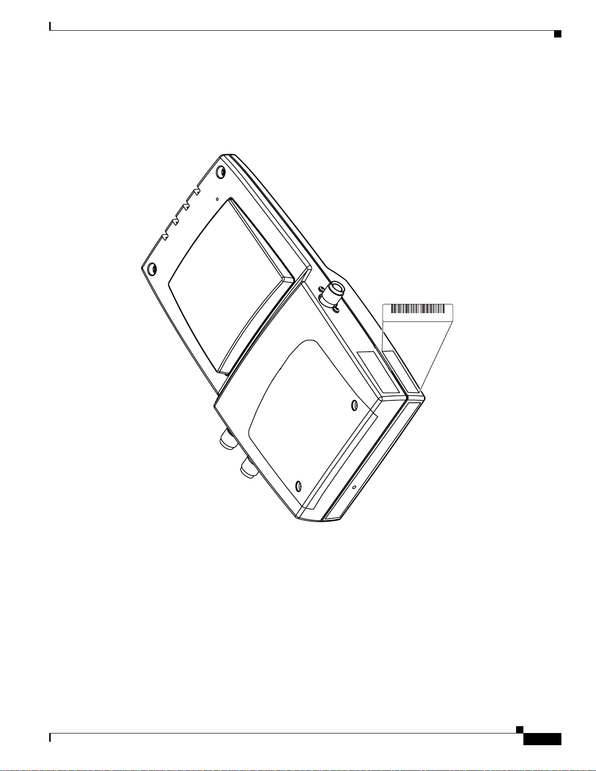
The access point seria l number is on th e right side of the housin g (refer to Figure 1).
Figure 1 Location of Serial Number Label
Finding the Product Serial Number
SN: XXXNNNNXXXX
142610, 781-000439-01 A0
The access point serial number label contains the following information:
• Model number, such as AIR -AP1 000-x -k9
• Serial number, such as VDF0636XXX X (11 alpha numeric di gits)
• MAC address, such as 00abc65094f3 (12 hexadecimal digits)
OL-9403-04
• Location of manufactu re, such as Made in Singapore
You ne ed your pro duct serial number whe n requesti ng support from the Cisco Technical Assistance
Center.
Cisco Aironet 1000 Series Lightweight Access Point Hardware Installation Guide
xi
Page 12

Obtaining Documentation, Obtaining Support, and Security Guidelines
Obtaining Documentation, Obtaining Support, and Security
Guidelines
For information on obtaining docume ntatio n, obtaini ng support , providing docum entat ion fee dback,
security guidelines, and also recommended aliases and general Cisco documents, see the monthly
What’s New in Cisco Product Documentation, w hic h also li sts a ll new and revised C i sco technical
documentation , at:
http://www.cisco.com/en/US/docs/general/whatsnew/whatsnew.html
Preface
xii
Cisco Aironet 1000 Series Lightweight Access Point Hardware Installation Guide
OL-9403-04
Page 13

CHA PTER
1
Overview
The Cisco Aironet 1000 Ser ies Light weight A ccess Points (h ereaft er call ed access points) combine
mobility and flexib ility w ith the ent erp ri se-c lass feat ur es requ ire d by n etwor king pr ofession al s. T he se
access points are part of the Cisco Integrated Wireless Network Solution and require no manual
configuration before they are mounted. The access point is automatically configured by a Cisco Wireless
LAN Controlle r (h erea ft er ca ll ed a controller) using the Light we ig h t Acc e s s P o in t P ro t oco l (LWA PP ).
The access po int c onta ins t wo i ntegra ted radi o s: a 2.4- GHz r adi o (IE EE 8 02.11g ) and a 5 -G Hz radi o
(IEEE 802.11a). Us ing a cont roller, you can configure the radios sep arate ly with di fferent setti ngs on
each.
In the Cisco Centralized Wireless LAN Architecture, access points operate in the lightweight mode (as
opposed to autonomous mod e). The ac cess poin ts associ ate to a contro ller. The controller ma nages the
configuration, f irmw are, and control tr ansactions such as 8 02.1x authentic ation. In ad dition, all wire less
traffic is tunneled through the controller.
LWAPP is an Inte rne t En gine eri ng Task Force (IETF) draft protocol th at define s the cont r ol me ssagin g
for setup and path authentication and run-time operations. LWAPP also defines the tunneling mechanism
for data traffic.
In an LWAPP environment, a lightweight access point discovers a controller by using LWAPP discovery
mechanisms and then sends it an LWAPP join request. The controller sends the access point an LWAPP
join response allo win g th e a cc ess po int to j oin the c ontr oller. When the access point is associated with a
controller, it downloads new operating system software if the versions on the access point and controller
do not match. After an access point is associated to a controller, you are able to reassign it to any
controller on your network.
L WAPP secures the contro l communicat ion between th e access p oint and contr oller by means of a secure
key distribution, utilizing X.509 certificates on both the access point and controller.
This chapter provides information on the following topics:
• Guidelines for Using the Access Points, page 1-2
OL-9403-04
• Hardware Features , pa ge 1-2
• Network Configuration Examp le, page 1-7
Cisco Aironet 1000 Series Lightweight Access Point Hardware Installation Guide
1-1
Page 14

Guidelines for Using the Access Points
Guidelines for Using the Access Points
You shou ld keep the se guideli nes in mind when you use t he access poi nts:
• The access points can only communicate with controllers and can not operate independently.
• The access points communicate only with co ntrollers a nd do not support Wireless Domain Services
(WDS). The access points cann ot communicat e with WDS de vices. Ho wev er , the contr oller prov ides
functionality equivalent to WDS when the access point associates to it.
• The access poin ts su ppor t L ay er 2 or Lay er 3 LWAPP comm un icatio ns w ith t he contro l lers . In
Layer 2 operation, the acce ss poi nt and the contr oller mu st be on the sam e subn et and co mmun icate
with each other using MAC addresses in encaps ulated Eth ernet fr ames . This opera tion is not
scalable to larger networks and not reco mmen ded by Cisco.
In Layer 3 operation, the access point an d the controlle r can be on the same or di fferen t subnets. The
access point communicates with the controller using standard IP packets. Layer 3 operation is
scalable and is recommende d by Cisco. A Layer 3 ac cess point on a different subnet than the
controller requires a DHCP server on the access point subnet and a route to the controller. The route
to the controller must have destinati on UDP ports 12222 and 12223 open for LWAPP
communications. The route to the primary, secondary, and tertiary controllers must allow IP packet
fragments.
• Before deploying your access poi nts ensure t he following has been done :
Chapter 1 Overview
–
Your c ontro llers a re c onn ect ed t o swi tch port s tha t a re co nfigured as tru nk port s.
–
Your access points are connected to switch ports that are configured as untagged access ports
–
A DHCP server is re ac habl e by yo ur acc ess poin ts a nd has b ee n co nfigur ed w ith Opt ion 43 .
Option 43 is used to provide the IP addresses of the Management Interfaces of your controllers.
Typically, a DHCP server can be configured on a Ci sco sw itch.
–
Optionally a DNS server can be configured to enable “CISCO-LWAPP-CONTROLLER.<local
domain>” to resolve to the IP address of the Management Interface of your controller.
–
Your controllers are configured and reachable by the access points.
Hardware Features
Key hardware features of the access point inclu de:
• Single or dual-radio oper ation (see page 1-4)
• Ethernet port (see page 1-5)
• LEDs, (see page 1-5)
• Multiple power sources (see page 1-5)
• Anti-theft features (see page 1-6)
• UL 2043 certificatio n ( see pa ge 1-6)
1-2
Refer to Appendix C, “Access Point Specifications,” for a list of access point specifications.
Figure 1-2 shows the access point.
Cisco Aironet 1000 Series Lightweight Access Point Hardware Installation Guide
OL-9403-04
Page 15
Chapter 1 Overview
Hardware Features
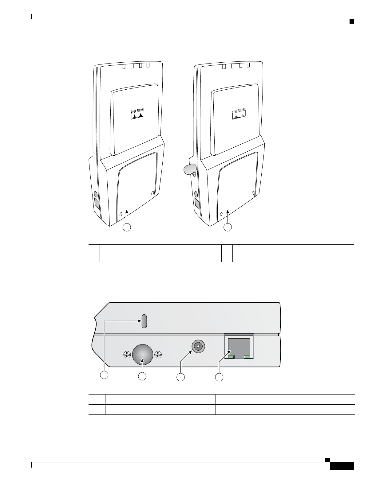
Figure 1-1 Access Point Configurations
Power
Alarm
2.4 GHz
5 GHz
1 2
5 GHz
2.4 GHz
Power
Alarm
146971
1 Integrated anten nas on ly (AIR- A P1010 ) 2 Integrated antennas and external antenna
connectors (AIR- AP1020 and A IR-A P103 0)
Figure 1-2 illustrates the left side connectors on the access point.
Figure 1-2 Access Point Left Side Connectors
24 GHz Left
48 v
250Ma
1
2
3 4
Ethernet
146973
1 Security key slot 3 48-VDC power port
2 2.4-GHz antenna connector (left) 4 Ethernet port (RJ-45)
OL-9403-04
Cisco Aironet 1000 Series Lightweight Access Point Hardware Installation Guide
1-3
Page 16
Hardware Features
Chapter 1 Overview
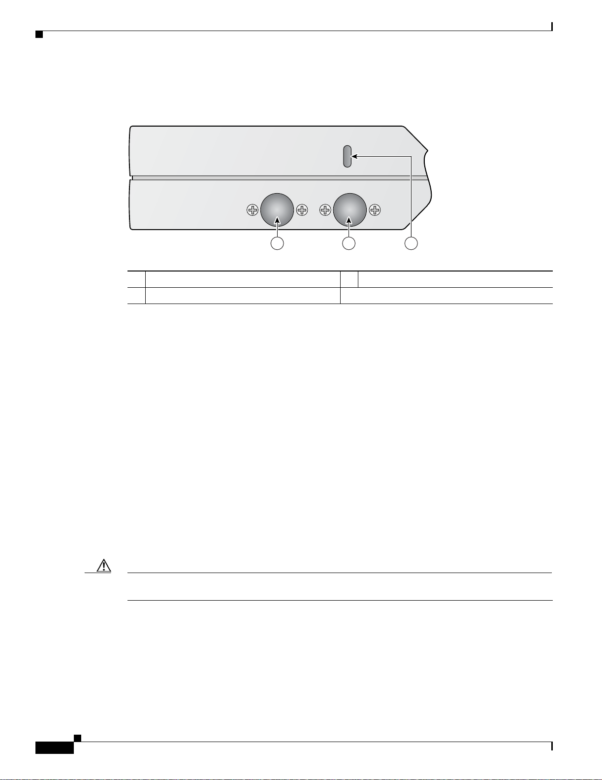
Figure 1-3 illustrates the right side connectors on the access point.
Figure 1-3 Access Point Right Side Connectors
5 GHz 24 GHz Right
1 5-GHz antenna c onnec to r (r i ght) 3 2.4-GHz antenna c onnec tor (r ight)
2 Security key slot
Single or Dual-Radio Operation
The access point support s single or simult aneous du al radio ope ration usi ng a 2.4-GHz 802.11g radio
and a 5-GHz 802.11a radio. The radios use integrated sector patch antennas or external antennas (see the
“Antennas Supported ” secti on).
The 5-GHz rad io i ncor por ate s a n Unl ice nsed N ationa l I nf orm ati on In fr ast ruc ture ( UNI I) radi o
transceiver operating in the UNII 5-GH z freq uency bands.
Antennas Supported
The access po in ts are availab le i n th re e co nfigur at ions :
• AIR-AP1010—Support s only integrate d anten nas
• AIR-AP1020—Supp orts integrate d and externa l antenna s
• AIR-AP1030—Supp orts integrate d and externa l antenna s
The 2.4 GHz a nd 5 GHz r adi os h ave two integrate d 6 d Bi di rec tiona l p atc h a nte nnas. T he i ntegra ted
antennas provide diversity operation for the 2.4 GHz radio. The antennas are located on the front and
back sides of the access point.
1 2 3
146975
1-4
Caution The access point, the antennas, and the power source (power injector or power module) are not designed
for outdoor use a nd mu st be loca ted in an ind oor environment .
Cisco Aironet 1000 Series Lightweight Access Point Hardware Installation Guide
OL-9403-04
Page 17
Chapter 1 Overview
Hardware Features
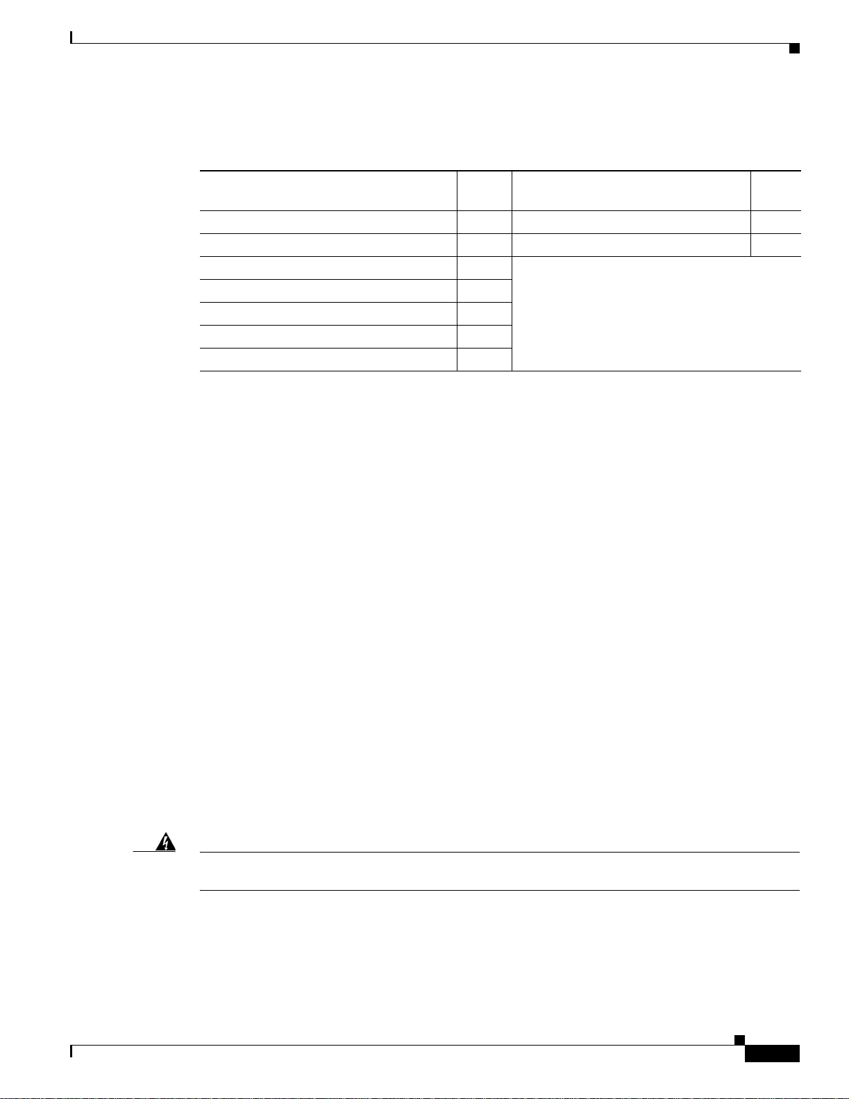
Table 1-1 lists the suppo rte d exte rnal ant enna s.
Table 1-1 Supported External Antennas
Ethernet Port
LEDs
2.4-GHz Antennas
AIR-ANT5959 diversity omnidirectional
Gain
(dBi) 5-GHz Antennas
2.0
AIR-ANT5135D-R omnidirectional
Gain
(dBi)
3.5
AIR-ANT4941 dipole 2.2 AIR-ANT5160V-R omnidirectional 6.0
AIR-ANT1728 omnidirectional 5.2
AIR-ANT2506 om nidir ect iona l 5.2
AIR-ANT3213 diversity omnidirectional
5.2
AIR-ANT1729 patch 6.0
AIR-ANT2012 diversity patch 6.5
The auto-sensing Ethernet port accepts an RJ-45 connector, linking the access point to your 10BASE-T
or 100BASE-T Ethernet LAN (see Figure 1-2). The access point can r ecei ve p owe r throug h the Ethe rnet
cable from a power injector, switch, or power patch panel. Th e Eth er ne t MAC address is printe d on the
label on the side of the access point (refer to the “Finding the Product Ser ial Nu mber” sec tion on
page xi).
The access point has four LE Ds to provide a visual in dicati on of access poi nt opera tions (refe r to the
“Checking th e A cce ss Poin t LE D s” secti on on p age 3-3 for additional information).
Power Sources
Warning
• Power LED
• Alarm LED
• 2.4 GHz LED
• 5 GHz LED
The access point can receive power from an external power module or from inline power using the
Ethernet cable . The ac cess point s uppo rts th e IEE E 80 2.3 af inli ne power stan da rd. U sing i nlin e power,
you do not need to run a power cord to the a cces s point becau se power is suppl ied over the Etherne t
cable.
This product must be connected to a Power over Ethernet (PoE) IEEE 802.3af compliant power source
or an IEC60950 compliant limited power source.
Statement 353
OL-9403-04
Cisco Aironet 1000 Series Lightweight Access Point Hardware Installation Guide
1-5
Page 18

Hardware Features
The access poin t sup por ts t he f ol lowing power sour ce s:
• Power module (AIR-PWR-1000= )
• Inline power:
Note The access point requires 12 W of inline power. Some switches and patch panels might not provide
enough power to operate the access point. If the access point is unable to determine that the power source
can supply sufficien t po wer, the access point does not activate the radios and does not turn on the Power
LED.
UL 2043 Certification
The access point has adequ ate fire resis tance and low smoke-pro ducing ch aract eristics sui table for
operation in a building's environmental air space, such as above suspended ceilings, in accordance with
Section 300-22(c) of the NEC, and with Sec tions 2- 128, 12-0 10(3) and 12- 100 of the Canadian
Electrical Code , Part 1, C 22. 1.
Chapter 1 Overview
–
Cisco Aironet 1000 series acc ess point power injector (AIR-PWRINJ-1000AF=)
–
An inline power capable swi tch, s uch a s th e Cisc o C ataly st 35 50 PWR X L, 3 560- 48PS,
3570-48PS, 4500 with 802.3A F PoE module, or the 650 0 with 802.3A F PoE module
–
Other inline power swi tc hes sup port ing the IE EE 802. 3a f inlin e power stan da rd
Caution Access points mounted in a building’s environmental air space must be powered usin g Po E to c ompl y
with safety regulations.
Caution The external antennas, the power inject or (AIR-P WRIN J-1000AF =) and th e power module
(AIR-PWR-1000=) are not tested to UL 2043 and should not be placed in a building’s environmental air
space.
Caution The Ethernet cables to your access points must be rated for above the ceiling mounting.
Anti-Theft Features
The access poin t sup por ts t wo sec ur ity c abl e keyholes (se e Figure 1-2 and Figure 1-3) to secure the
access point using a standard security cable, like those used on laptop computers.
1-6
Cisco Aironet 1000 Series Lightweight Access Point Hardware Installation Guide
OL-9403-04
Page 19
Chapter 1 Overview
1
Network Configuration Example
The access poin ts su ppor t L ay er 2 or Lay er 3 ne twor k o pera tio n. In L ayer 2 configur ation s, t he a cce ss
point and the controller are on the same subnet and communicate with encapsulated Ethernet frames
using MAC addresses rather than IP addresses. Layer 2 configurations are typically not scalable into
larger networks. Additionally, Layer 2 operation is supporte d only by the Cisco 440 0 se ries cont rol ler s.
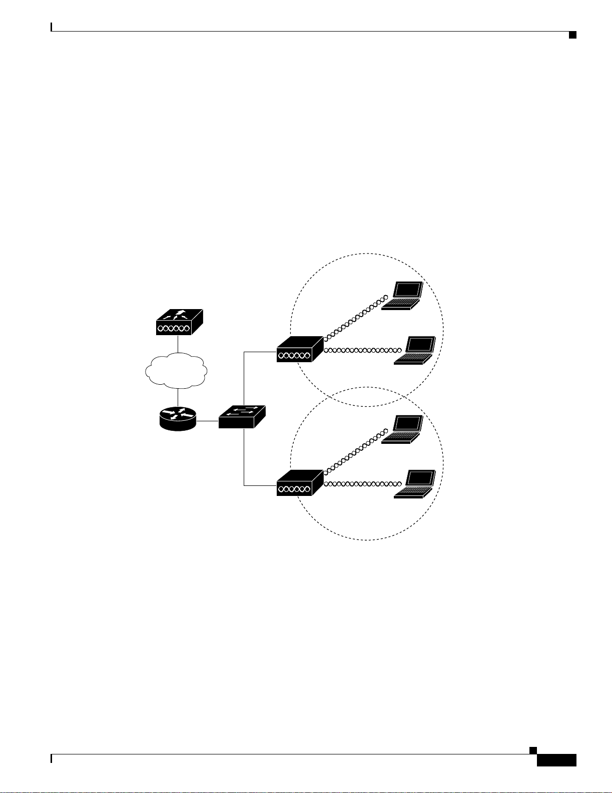
Access points and controller s in Layer 3 configurat ions use IP add resses and UDP packet s, which ca n
be routed through l arge netwo rks. L aye r 3 o pera tio n is sca lab le an d re comm end ed by Cisc o.
Figure 1-4 illustrates a typical Layer 3 wireless network configuration containing access points and a
controller.
Figure 1-4 Typical Layer 3 Access Point Network Configuration Example
Network Configuration Example
LWAPP
LWAPP
58085
OL-9403-04
Cisco Aironet 1000 Series Lightweight Access Point Hardware Installation Guide
1-7
Page 20
Network Configuration Example
1
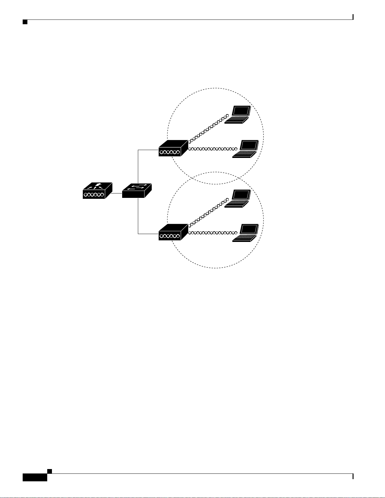
Figure 1-5 illustrates a typical Layer 2 network conf ig ura tion. In a La yer 2 c onfiguration, the controller
and the access points are on the same subnet.
Figure 1-5 Typical Layer 2 Access Point Network Configuration Example
Chapter 1 Overview
LWAPP
LWAPP
58084
1-8
Cisco Aironet 1000 Series Lightweight Access Point Hardware Installation Guide
OL-9403-04
Page 21

CHA PTER
2
Installing the Access Point
This chapter describes the installation of the access point and includes these sections:
• Safety Informat ion, p ag e 2-2
• Warnings, page 2-2
• Unpacking the Access Po int, page 2-3
• Basic Installation Guidelines, page 2-3
• Before Beginning the I nsta llat ion, pag e 2-4
• Controller Discovery Process, page 2-6
• Controller Discovery Process, page 2-6
• Mounting Overview, page 2-8
• Securing the Acce ss Po int U sing a Se cu rity C ab le, page 2-17
• Connecting the Ethernet and Power Cables, page 2-17
• Powering Up the Access Point, page 2-19
• Returning MAC Information , pag e 2-20
OL-9403-04
Cisco Aironet 1000 Series Lightweight Access Point Hardware Installation Guide
2-1
Page 22

Safety Information
Safety Information
Follow the guidelines in this section to ensure proper operation and safe use of the access point.
FCC Safety Compliance Statement
The FCC with its action in ET Docket 96-8 has adop ted a safet y standar d for human exposur e to radio
frequency (RF) electromagnetic energy emitted by FCC certified equipment. When used with approved
Cisco Aironet antennas, Ci sco Airo net product s meet th e uncontrol led environmental limits found i n
OET-65 and ANSI C95.1, 1991. Prop er insta llation of this radio ac cord ing to the ins tructio ns found in
this manual will result in user exposure that is substantially below the FCC recommended limits.
General Safety Guidelines
Do not hold any c ompone nt co nt ain in g a ra di o so t h at the an t enn a i s ver y cl ose to or tou ch ing any
exposed parts of the body, especially the face or eyes, while transmitting.
Chapter 2 Installing the Access Point
Warnings
Warning
Warning
Warning
Translated v ersions of all safety wa rnings are a vailable in the safety warning document that shipped with
your access poin t or on Cisc o.co m. To browse to the documen t on Cisc o. co m, re fer to Appendix A,
“Translated Safety Warnings” for instructions.
This warning symbol means danger. You are in a situation that could cause bodily injury. Before you
work on any equipment, be aware of the hazards involved with electrical circuitry and be familiar
with standard practices for preventing accidents. Use the statement number provided at the end of
each warning to locate its translation in the translated safety warnings that accompanied this device.
Statement 1071
SAVE THESE INSTRUCTIONS
Do not operate your wireless network device near unshielded blasting caps or in an explosive
environment unless the device has been modified to be especially qualified for such use.
Statement 245B
In order to comply with FCC radio frequency (RF) exposure limits, antennas should be located at a
minimum of 7.9 inches (20 cm) or more from the body of all persons.
Statement 332
2-2
Warning
Warning
Cisco Aironet 1000 Series Lightweight Access Point Hardware Installation Guide
This product must be connected to a power-over-ethernet (PoE) IEEE 802.3af compliant power source or an
IEC60950 compliant limited power source.
Read the installation instructions before you connect the system to its power source.
Statement 353
Statement 1004
OL-9403-04
Page 23

Chapter 2 Installing the Access Point
Unpacking the Access Point
Warning
This product relies on the building’s installation for short-circuit (overcurrent) protection. Ensure that
the protective device is rated not greater than: 20A
Unpacking the Access Point
Follow these steps to unpack the access point:
Step 1 Open the shipping container and carefully remove the contents.
Step 2 Return all pack i ng ma ter ials t o t he sh ippi ng conta ine r and save it.
Step 3 Ensure that all items listed in the “Package Contents” section are included in the shipment. Check each
item for damage. If any item is damage d or missin g, notif y your autho rized Cisc o sales repre sentat ive.
Package Contents
Each access point pack age co ntain s the foll owing items:
• Cisco Aironet 1000 series light weight access point
• Ceiling mount kit (ceiling-mount base, two ceiling-mount clips, two screws, and two washers)
• Quick Start Guide: Cis co A ironet 1000 Seri es Li ghtw eigh t Ac cess Points
Statement 1005
• Translated Safety Warnings for Cisco Aironet 1000 Series Lightweight Access Po ints
• Cisco product registration an d Cisco docum entati on feedba ck card s
Basic Installation Guidelines
Because the acc ess poin t i s a ra dio device, it is su sce pti ble to int erfe renc e t hat can r edu ce thro ughp ut
and range. Follow these basic guidelines to ensure the best possible performance:
• Ensure a site survey has been performed to determine the optimum placem ent of access points. Refer
to the Cisco Aironet 1000 Series Light weig ht A cce ss Point Deployment Guide fo r site survey
information.
• Check the latest release notes to ensure that your controller software version supports the access
points to be insta lled. You can find the controller release not es by se lec ting y our con trol ler unde r
Wireless LAN Controllers at this URL:
http://www.cisco.com/en/US/products/hw/wireless/tsd_produ cts_support_c ategory_home.html
• Ensure that access points are not mounted closer than 20 cm (7.9 in) from
• Do not mount the access point within 3 ft (91.4 cm) of metal obstructions. Refer to the Cisco Aironet
1000 Series Lightweight Acce ss Point Deployment Guide for additional information.
• Install the access point away from microwave ovens. Microwave ovens operate on the same
frequency as the access point and can ca use signa l interfe rence .
• Always mount the acce ss p oint vertic ally (st andin g u p o r hangi ng down).
the body of all persons
.
OL-9403-04
Cisco Aironet 1000 Series Lightweight Access Point Hardware Installation Guide
2-3
Page 24
Before Beginning the Installation
• Do not mount the ac cess point out side o f buildings.
• Do not mount the a cce ss poi nts on building perime ter walls unl ess out side coverage is de sire d.
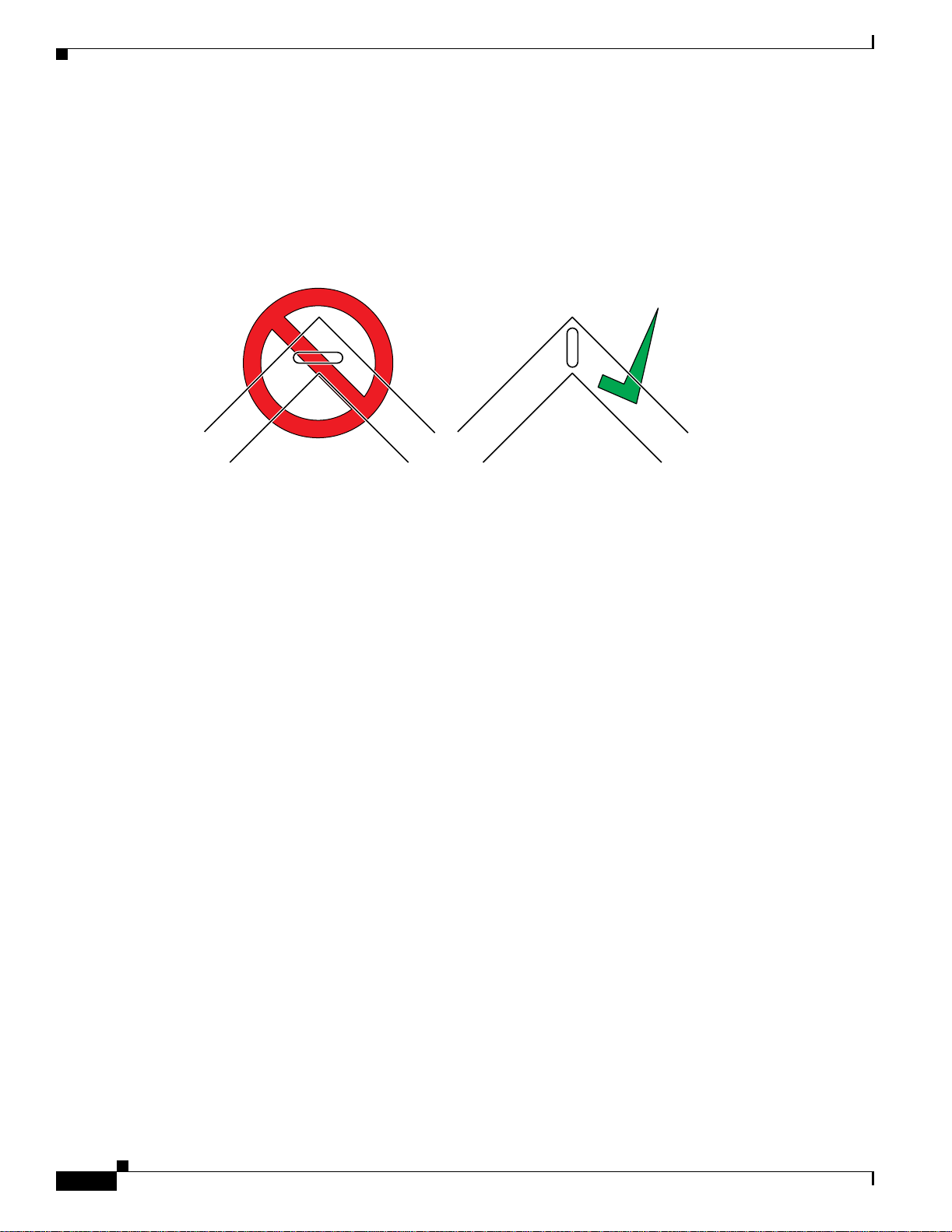
• When mounting an access point in the corner of a right-angle hallway intersection, mount the access
point at a 45-degree ang l e to the t wo ha llways (s ee Figu re 2 -1). The ac cess point int ern al a nte nna s
are not omnidirectio nal and cover a larger are a when mou nted thi s way.
Figure 2-1 Mounting the Access Point in the Correct Direction
Chapter 2 Installing the Access Point
135660
Ensure that the access point is on the same subnet as the primary, secondary, or tertiary controllers
•
or has a DHCP server on the subnet with a route to the controllers.
Before Beginning the Installation
Before you begin the installation, review these sections to become familiar with the access point, the
mounting hardware, and t he d ep loymen t pr oc ed ure:
• Access Point Layout a nd Co nne cto rs, page 2-5
• Controller Discovery Process, page 2-6
• Controller Discovery Process, page 2-6
• Mounting Overview, page 2-8
2-4
Cisco Aironet 1000 Series Lightweight Access Point Hardware Installation Guide
OL-9403-04
Page 25
Chapter 2 Installing the Access Point
Access Point Layout and Connectors
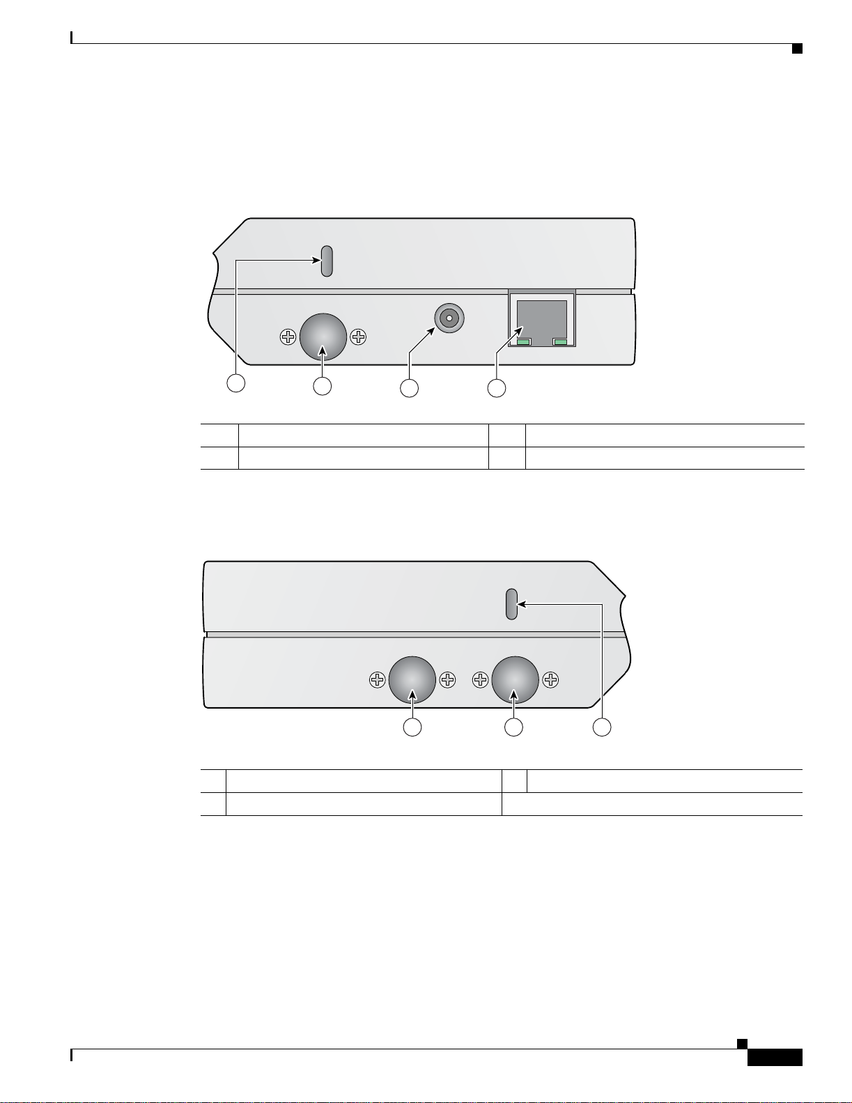
Figure 2-2 illustrates the connectors on the left side of the access point.
Figure 2-2 Access Point Left Side Connectors
24 GHz Left
Before Beginning the Installation
48 v
250Ma
1
2
3 4
Ethernet
1 Security cable keyslot 6 48-VDC power port
2 2.4-GHz antenna connector (left) 7 Ethernet port (RJ-45)
Figure 2-3 illustrates the right side of the access point.
Figure 2-3 Access Point Right Side Connectors
5 GHz 24 GHz Right
1 2 3
146973
146975
OL-9403-04
1 5-GHz antenna connector 3 Security cable keyslot
2 2.4-GHz antenn a connec tor (rig ht)
Cisco Aironet 1000 Series Lightweight Access Point Hardware Installation Guide
2-5
Page 26

Controller Discovery Process
Figure 2-4 illustrates the access point LEDs on the top of the unit.
Figure 2-4 Access Point LEDs
Chapter 2 Installing the Access Point
1 2 3 4
5 GHz
2.4 GHz
side A
1 5-GHz LED 3 Alarm LED
2 2.4-GHz LED 4 Power LED
Controller Discovery Process
Alarm
Power
146972
2-6
The access poin t sup port s the se c ontr oll er disc overy proc esses:
• Layer 2 LW APP dis cov ery—O nly se nt on the s ame subn et as the ac cess p oint an d uses e ncapsul ated
Ethernet frames containing MAC addresses for communication between the access point and the
controller. Encapsulated E t herne t f ram es a re not suitabl e f or L ayer 3 depl oyment s wher e the
controller is not on the same subnet as the access points.
• Over-the-air wireless discovery—If enabled on the controller, all the associated access points
transmit wireless LWAPP neighbor messages. New access points receive the controller IP address
from the wireless LWAPP neighbor messages. This feature should be disabled when all access points
are installed. Also, this feature is only supported by Cisco1000 series lightweight access points and
Cisco 4400 controller s.
• Locally stored contr oller IP addre sses—If the ac cess point wa s pre viously ass ociated to a co ntroller ,
the IP addresses of the primary, secondary, and tertiary controllers are stored in the access point
non-volatile memory. The process of storing controller IP addresses in access points for later
deployment is call ed pr i ming the ac cess poi nt. For addi ti onal in for mat ion, refe r to the “P r iming
Access Points Prior to Deployment” secti on on page E-1.
Cisco Aironet 1000 Series Lightweight Access Point Hardware Installation Guide
OL-9403-04
Page 27

Chapter 2 Installing the Access Point
Deploying the Access Points on the Wireless Network
• DHCP server discovery—Uses DHCP Option 43 to provide controller IP addresses to the access
points. Cisco switches support a DHCP server option. For additional information, refer to the
“Configuring DHCP Option 43” sec tion on page F-1.
• DNS server discovery—The access poi nt uses the name CISCO-LWAPP-CONTROLLER.<local
domain> to discover the cont rolle r IP addr esses from a DN S server. Where <lo cal domain> is the
access point doma in n am e.
Cisco recommends that you co nfigure a DHC P server with Opti on 43 to provide the control ler IP
addresses to your access points. Cisco switches provide a DHCP server option that is typically used for
this purpose.
Deploying the Access Points on the Wireless Network
Prior to beginning t he a ct ual acc ess poi nt de ployme nt, p erfor m thes e tasks :
• Ensure a site survey has been preformed.
• Ensure your network infr astruc ture devices are oper ation al and pro perl y configured.
• Ensure your con troll ers a r e co nne cte d t o swi tc h tr unk po rts.
• Ensure your switc h is co nfigur ed w ith u ntag ged a cce ss ports fo r conne c ting y our a ccess p oi nts.
• Ensure a DHCP server with Opti on 43 configured is reacha ble by your acces s points .
• Review the “Mounting Overview” section on page 2-8.
To deploy your access points, follow these steps:
Step 1 Obtain the access point location map created during your building site survey.
Step 2 Review the access point locations and identify the specific mounting methods required for each access
point location.
Step 3 For each access point perform these steps:
a. Record the access point MAC address on the access point location map (see the “Returning MAC
Information” section on page 2-20).
b. Mount the access point at the indica te d d estina tion usi ng t he sp ec ified mo unti ng me tho d. For
specific mounting instructions, see these sections:
–
Horizontal surface, such as a ceiling (see the Mounting Access Points Using a Ceil ing- Mount
Base, page 2-10).
–
Below a suspended ceiling (see the “Mounting Access Points Using the Ceiling-Mo unt Clips”
section on page 2-11).
–
Perpendicular to a ver tica l surf a ce, such a s a w all ( see th e “Mounting the Access Point Using a
Projection Wall Mount Bracket” section on page 2-13 ).
–
Parallel to a vertical surface, such as a wall ( see the “Mounting the Access Point Using the
Flush-Mount Bracket” secti on on page 2-15).
c. Optio n all y s e cu re th e access point using a s e cu rity cable (see the “ Secur in g the Acc ess Poin t Using
a Security Cable” section on page 2-17).
OL-9403-04
d. Connect the access point cables (Ethernet, optional power, optional antennas). For instructions see
the “Connecting the Ethe rnet and Power Cab les” se ct ion o n page 2-17.
Cisco Aironet 1000 Series Lightweight Access Point Hardware Installation Guide
2-7
Page 28

Mounting Overview
e. On power up, verify that the access point is associated to a controller and operating normally. The
Power LED should be green, the Alarm LED should be off, and the radio LEDs should be blinking.
For additional information, see the “Powering Up the Access Point” section on page 2-19.
Step 4 After all access points are deployed and operating correctly, ensure that a controller is not configured as
a master controll er. A master cont rol ler sh ould only be u se d f or configuri ng ac c ess po ints and not i n a
working network.
Mounting Overview
You ca n mount the access poin t on any of the following surfac es:
• Horizontal or vertical flat surfaces, such as walls or ceilings
• Suspended ceilings (above and below)
Caution The access point, the antennas, and the power source (power injector or power module) are not designed
for outdoor use a nd mu st be loca ted in an ind oor environment .
Chapter 2 Installing the Access Point
Caution The po we r i nj ec to rs and po wer module s should not be placed in a b uilding ’ s env ironmental ai r space, such
as above suspended ceilings.
Note The access point pro vides adequa te f ir e res istance and lo w smok e-pr oduci ng ch aracte rist ics suit able fo r
operation in a building's environmental air space (such as above suspended ceilings) in accordance with
Section 300-22(C) of the National Electrical Code (NEC).
Note When mounting the access point in a building’s environmental air space, you must use only the metal
projection-mount or the flush-mount brac ket s (not the plastic ce iling-m ount base or the hangi ng-ceilin g
clips), and the access point must be powered using PoE. Also, onl y the integrated ant ennas can be used .
Note When mounting the access point in a building’s environmental air space, you must use Ethernet cable
suitable for operation in environmental air space in accordance with Section 300-22(C) of the National
Electrical Code (NEC).
The access po int sup por ts moun tin g h ar dware t o all ow wall, ce il ing, or su spe nded ce il ing mou nting:
• Ceiling-mount base for mounting the access point to a horizontal surface–supplied with the access
point (see Figure 2-5)
• Two suspended ceiling hanging-cl ips for mounting the access point be low a suspended
ceiling–supplied with t he a cce ss poi nt ( see Figure 2-6)
2-8
• Metal projection-mount bracket (user orderable) for mounting the access point to a vertical wall (see
Figure 2-6)
Cisco Aironet 1000 Series Lightweight Access Point Hardware Installation Guide
OL-9403-04
Page 29

Chapter 2 Installing the Access Point
• Metal flush-mount bracket (user orderable) for mounting the access point to a vertical wall (see
Figure 2-6)
• Ceiling-mount bezel ki t (user ordera ble) for mounting the access poin t above a suspended ceilin g
tile. For additional information, refer to the Quick Start Guide: Ceiling Mount Bezels for Cisco
Aironet 1000 Series Lightweight Access Points.
Figure 2-5 Factory-Supplied Mounting Options
Mounting Overview
A. Ceiling-mount base
Figure 2-6 Orderable Mounting Brackets
A. Projection-mount bracket
B. Hanging ceiling clips
B. Flush-mount bracket
135663
135661
Refer to the Table 2-1 to identify the mat erials you ne ed to mount your acce ss point, then go to the
section containing the spe cific mountin g procedur e.
Table 2-1 Material Needed to Mount Access Point
Mounting Method Materials Required Supplied
Horizontal sur face Ceiling-mount base wi th t wo sc rews and two washers
Two screws and optional wall anc hor s
Standard screwdriver
Drill and drill bit
Suspended ceiling Two hanging-clips with two screws and two washers
Standard screwdriver
Vertical surface Projection-mount bracket with two screws and two washers
Four screws and optional wall anchors
Standard screwdriver
Drill and drill bit
Ve rtical surfac e Flush-mount bracket with two screws and two washers
Four screws and optional wall anchors
Standard screwdriver
Drill and drill bit
Yes
User supplied
User supplied
User supplied
Yes
User supplied
Orderable
User supplied
User supplied
User supplied
Orderable
User supplied
User supplied
User supplied
OL-9403-04
Cisco Aironet 1000 Series Lightweight Access Point Hardware Installation Guide
2-9
Page 30

Mounting Overview
Mounting Access Points Using a Ceiling-Mount Base
When you are mounting the access point to horizontal surface, such as the ceiling of a building, use the
ceiling-mount base to mount the acce ss point. Th e ceiling- mount b ase can also be used to mo unt th e
access point to a desktop or shelf.
Figure 2-7 Attaching the Access Point and Ceiling-Mount Base
Chapter 2 Installing the Access Point
135664
Follow these steps to attach the ceiling-mount base to the access point and mount the access point to a
horizontal surface, such as a ceiling.
Step 1 Copy the MAC address(es) from the label(s) on the access point onto the corresponding location on your
access point loc ation m ap. MAC addresse s h ave the fo rm at 0 0xx xxxxxx xx.
Step 2 Find the required moun ting lo cation as ide ntified on your ac cess point l ocation ma p.
Step 3 Use the ceiling-mount base to mark the two screw key slots on the ceiling location. ensure to leave
enough space aro und the ac cess point an d base to plu g t he CAT-5 cable , opt iona l ext erna l a nte nna
cable(s), optional power supply cable, and optional Kensington MicroSaver security cable into the sides
of the access point.
Step 4 Install two scre ws in the mark ed ke y slots locat ions. Use ap propriat e screws and anchors (user supplied ).
Tighten the screws until the heads are about 1/8 inch from the ceiling surface.
Step 5 Attach the ceiling-mount base to the bottom of the access point using the factory-supplied machine
screws and washers (refer to Figure 2-7).
Step 6 Position the access point with the ceiling-mount base so its keyhole slots are on over the screw heads
and slide the ceiling-mount base in the direction of the key slots.
Note If the ceiling screws do not securely hold the access point, remove the ceiling-mount base and
tighten the ceiling screws until they hold the access point securely.
2-10
Cisco Aironet 1000 Series Lightweight Access Point Hardware Installation Guide
OL-9403-04
Page 31

Chapter 2 Installing the Access Point
Step 7 Attach the cables to the access point.
Note When the access point is powered up and is associated with a controller (Power LED is green,
Alarm LED is off, an d the r adio LED s are blin king), the a ccess poin t is broadc asting its b eacon.
Step 8 Repeat the these steps for each access point on a horizontal surface.
After mounting all h or izo n tal s ur f a ce access points, retur n t o de ploying the access p o in ts , "Step 3-c" on
page 2-7.
c
Mounting Access Points Using the Ceiling-Mount Clips
When you are mounting the access point under a suspended ceiling, use the ceiling-mount clips to mount
the access point to the suspended ceiling rails.
Figure 2-8 Attaching the Ceiling-Mount Clips to the Access Point
Mounting Overview
OL-9403-04
135665
Follow these steps to attach the ceiling-mount clips to the access point and mount the access point to
suspended ceiling rails:
Step 1 Copy the MAC address from the label on the access point onto the corresponding location on the access
point location m ap. MAC addresses have the for mat 0 0xx xxxx xxx x.
Step 2 Attach the ceiling-mount clips to the bottom of the access point using the factory-supplied machine
screws and washers (see Figure 2-8).
Cisco Aironet 1000 Series Lightweight Access Point Hardware Installation Guide
2-11
Page 32

Mounting Overview
Step 3 Snap the ceiling-mount clips onto a suspended ceiling r ail (see Figure 9). Ensure you leave enough space
Chapter 2 Installing the Access Point
around the acc ess po int t o plug the E the rnet ca ble, o ptiona l ext erna l a nten na cab le( s), op tio nal power
supply cable, and optional Kensington MicroSaver security cable into the sides of the access point.
Figure 9 Mounting the Access Point with Ceiling-Mount Clips to a Suspended Ceiling Rail
2-12
Step 4
Attach the cables (Ethernet and optional antennas) to the sides of the access point.
Note Ensure that the cables are routed away from the access point integrated antennas.
Note When the access point is powered up and is associated with a controller (Power LED is green,
Alarm LED is off, and the radio LEDs are blinking), the access point radios are operational and
broadcasting their beac ons.
Step 5 Repeat Steps 1 to 4 for each suspe nded ceili ng access point location .
After mounting all suspended ceiling access points, return to deploying the access points, "Step 3-c" on
page 2-7.
Cisco Aironet 1000 Series Lightweight Access Point Hardware Installation Guide
135674
OL-9403-04
Page 33

Chapter 2 Installing the Access Point
Mounting the Access Point Using a Projection Wall Mount Bracket
When you are mounting t he a cce ss point out fro m a vertica l wall (flat side s alon g the wall or h allway) ,
use an optional factory-ord erab le proj ection- mount L-bracket (se e Figure 2-6). Follow these steps to
attach the ac cess point t o the proje ct ion-m ou nt br ac ket an d m ount the ac cess poi nt to a vertic al wall :
Step 1 Before proceeding, gently screw the two factory-supplied screws and spring washers into the bottom of
the access point (see Figure 2-10). Ensure the spring washers have their co nvex (high center sec tio ns)
pointing toward the screw heads.
Note Do not tighten the screw hea ds flush with the access point surf ace or the bracket will not f it under
the screw heads.
Figure 2-10 Attaching the Mounting Screws to the Access Point
Mounting Overview
OL-9403-04
Step 2
A. Screws and spring washers B. Completed assembly
Copy the MAC address(es) from the label(s) on the access point onto the corresponding location on the
135667
access point loc ation m ap . MAC addre sses h ave the fo rm at 0 0xx xxx xxx xx.
Step 3 Find the required moun ting lo cation as ide ntified on your ac cess point l ocation ma p.
Step 4 Use the projection-mount bracket to mark the four screw holes on the wall. Ensure to leave enough space
around the access point and base to plug the CAT-5 cable, opt ional exter nal an tenna c able(s ), option al
power supply cable, and optional Kensington MicroSaver security cable into the sides of the access
point.
Step 5 Mount the pr oje ction- br acket t o the wall using f our sc rews in the m arked l oca ti ons. U se appr op riat e
screws and wall anchors (user supplied). Tighten the wall screws.
Step 6 Position the two screws in the base of the access point over the projection-bracket keyhole slots and slide
the access point in the direction of the key slots (see Figure 2 -11). If you are unable to attach the access
point to the bracket, remove the access po int and loose n the two acc ess point screws.
Note After attaching the access point to the bracket, tighten the screws until they securely hold the
access point.
Cisco Aironet 1000 Series Lightweight Access Point Hardware Installation Guide
2-13
Page 34

Mounting Overview
Chapter 2 Installing the Access Point
Figure 2-11 Attaching the Access Point to the Projection-Mount Bracket
Step 7
Attach the cabl es to the s ide s of the a cces s poi nt. T he E therne t cab le, o ptio nal e x ternal ant enna ca bl e(s),
optional power supply cable, and optional Kensington MicroSaver security cables can be routed through
the large holes in the mounting bracket.
Note Ensure that the cables are routed away from the access point integrated antennas.
Note When the access point is powered up and is associated with a controller (Power LED is green,
2.4 GHz LED is yellow, and 5.4 GHz LED is amber), the access point is broadcasting its beacon.
Step 8 Repeat Steps 1 to 7 for each p rojectio n-moun t bracket lo cation.
After mounting all your projection-mount access points, return to deploying the access points, "Step 3-c"
on page 2-7.
135671
2-14
Cisco Aironet 1000 Series Lightweight Access Point Hardware Installation Guide
OL-9403-04
Page 35

Chapter 2 Installing the Access Point
Mounting the Access Point Using the Flush-Mount Bracket
When mounting the access point against a vertical wall (flat side toward the inside of the building), use
an optional factory-orderable flush-mount bracket. Follow these steps to mount the bracket and attach
the access point:
Step 1 Before proceeding, gently screw the two factory-supplied screws and spring washers into the bottom of
the access point (see Figure 2-10). Ensure the spring washers have their co nvex (high center sec tio ns)
pointing toward the screw heads.
Note Do not tighten the screw hea ds flush with the access point surf ace or the bracket will not f it under
the screw heads.
Step 2 Copy the MAC address(es) from the labe l(s) on the access point onto the corresponding location on the
access point loc ation m ap . MAC addre sses h ave the fo rm at 0 0xx xxx xxx xx.
Step 3 Find the required moun ting lo cation as ide ntified on your ac cess point l ocation ma p.
Mounting Overview
Step 4 Use the flush-m ount brac ket to mar k the four scr ew holes on the wall . Ensur e to leave enough space
around the access point and base to plug the CAT-5 cable, opt ional exter nal an tenna c able(s ), option al
power supply cable, and optional Kensington MicroSaver security cable into the sides of the access
point.
Step 5 Mount the flu sh-m oun t br ac ket t o t he wa ll usi n g four sc rews in the m arked loca ti ons. U se app rop ria te
screws and wall anchors (user supplied). Tighten the wall screws.
Step 6 Position the two screws in the base of the access point over the flush-mount bracket keyhole slots and
slide the access point in the direction of the key slots (see Figure 2-12). If you are unable to attach the
access point to the bracket, remove the access point and loosen the two access point screws.
Note Ensure the side of the access point with the door is facing aw a y fr om th e w a ll. Th is ensu re s that
the correct ant enna is fac ing t he buil ding, and m akes fu ture u pgrad es ea sie r.
Note After attaching the access point to the bracket, tighten the screws until they securely hold the
access point.
OL-9403-04
Cisco Aironet 1000 Series Lightweight Access Point Hardware Installation Guide
2-15
Page 36

Mounting Overview
Chapter 2 Installing the Access Point
Figure 2-12 Attaching the Access Point to the Flush-Mount Bracket
135672
Step 7
Attach the cables to th e s id e s of the access point (the Ether n et c ab le, optional exte rn al an ten n a c ab le( s ),
optional power supply cable, and op tional Kensington Micro Saver security cabl e).
Note Ensure that the cables are routed away from the access point integrated antennas.
Note When the access point is powered up and is associated with a controller (Power LED is green,
Alarm LED is off, and the radio LEDs are blinking), the access point is broadcasting its beacon.
Step 8 Repeat Steps 1 to 7 for each flush- mount bra cket location .
After mounting all your flush-mount access points, return to deploying the access points, "Step 3-c" on
page 2-7.
2-16
Cisco Aironet 1000 Series Lightweight Access Point Hardware Installation Guide
OL-9403-04
Page 37

Chapter 2 Installing the Access Point
Securing the Access Point Using a Security Cable
Securing the Access Point Using a Security Cable
You can secure the access point by installing a standard security cable (such as the Kensington MicroSaver,
model number 64068) into the access point security cable slot (see Figure 2-3). The security cable can be
used with any of the mounting methods described in this guide provided the cable can be secured to a
nearby im mova bl e o bj e ct .
Follow these steps to install the security cable.
Step 1 Loop the security ca ble arou nd a nearby imm ovable object.
Step 2 Insert the key into the security cable lock.
Step 3 Insert the security cable latch into the security key slot on the access point.
Step 4 Rotate the key right or left to secure the security cable lock to the access point.
Step 5 Remove the key from security cable lock.
Step 6 Repeat Steps 1 to 4 for each access point requiring a security cable.
After securing your access points, go to the “Connecting to an Ethernet Network with an Inline Power
Source” section on p ag e 2-18.
Connecting the Ethernet and Power Cables
The access point receives power through the Ethernet cable or an external power module.
Warning
Caution This product and all inte rc onnec te d e quip ment m ust be i nsta lled indo ors w ithin the s ame building,
This product must be connected to a Power over Ethernet (PoE) IEEE 802.3af compliant power source
or an IEC60950 compliant limited power source.
including the associated LAN connections (as defined by Environment A of the IEEE 802.3af standard).
The access poin t power op tions:
• Option 1—Switches with sufficient inline power:
–
An inline power capable swit ch, s uc h as the Cisc o C ataly st 35 50 PWR X L, 3 560- 48PS,
3750-48PS, 4500 with 802.3A F PoE module, or the 650 0 with 802.3A F PoE module
–
Other inline power switches suppor ting the IE EE 802. 3af inlin e power standard
• Option 2—Switches without sufficient inline power can use the power injector:
–
Cisco Aironet Power Injector (AIR-PWRINJ-1000AF=)
• Option 3—Local power using the power mo dule (AIR -PWR-1 000=)
Statement 353
OL-9403-04
Cisco Aironet 1000 Series Lightweight Access Point Hardware Installation Guide
2-17
Page 38

Chapter 2 Installing the Access Point
Connecting the Ethernet and Power Cables
Note Some older switches and patc h panels migh t not provide enou gh power to operate th e acces s point. At
power-up, if the access point is unable to determine that the power source can supply sufficient power,
the access point automatically deactivates both radios to prevent an over-current condition. All access
LEDs are off.
Connecting to an Ethernet Network with an Inline Power Source
Note If your access point is connected to in-line power, do not connect the power module to the access point.
Follow these steps to connect the access point to the Ethernet LAN when you have an inline power
source:
Step 1 Connect a Category 5 Etherne t cable t o the RJ-45 Ethe rnet connec tor label ed Ethernet on the access
point (see Figure 2-13).
Step 2
Figure 2-13 Ethernet and Power Ports
24 GHz Left
48 v
250Ma
1 2
Ethernet
146974
1 Ethernet port 2 48 VDC power port
Connect the other end of t he Ether net cab le to one of the following:
• A switch with inline power (see the “Connecting the Ethernet and Power Cables” section on
page 2-17).
• The Ethernet conne ctor on the power injector (AIR-PWR INJ-100 0AF) label ed J1 DATA & PWR.
Also connect a Category 5 Ethernet cable from the power injector Ethernet connector labeled
J2 DATA to a non-powered Etherne t port on you r 10/100 Ethe rnet LA N.
2-18
Step 3 Repeat Steps 1 to 2 for each access poi nt requir ing in-line power.
Cisco Aironet 1000 Series Lightweight Access Point Hardware Installation Guide
OL-9403-04
Page 39

Chapter 2 Installing the Access Point
Connecting to an Ethernet Network with Local Power
Note If your access point is connected to in-line power, do not connect the power module to the access point.
Follow these steps to connect the access point to an Ethernet LAN when you are using a local power
source:
Step 1 Connect a Category 5 Etherne t cable t o the RJ-45 Ethe rnet connec tor label ed Ethernet on the access
point (see Figure 2-13).
Step 2 Plug the other end of the Et hernet cab le into an no n-powered Eth ernet port on your 10/100 Etherne t
LAN.
Step 3 Connect the power module output connector to the access point’s 48-VDC power port (see Figure 2-13).
Step 4 Plug the power mo dule power co rd i nto a n app roved 100 - to 24 0-VAC outlet.
Powering Up the Access Point
Powering Up the Access Point
After you power up the access point, it begins a power-up sequence that you can check by observing the
access point LED s. Th e re d Alar m LE D t urn s on f or a bout 15 to 20 secon ds an d the n a ll LE D s b link
sequentially back a nd fo rt h, i nd ica tin g th at th e a cces s po i nt i s trying t o find a co nt roll er. Refer to
“Checking the Acc ess Poi n t LE Ds” se ction on p age 3-3 for LED desc ript ion s.
After the access point finds the cont rolle r, the access point down load s new operating system code if the
access point code vers ion differs fr om the con trol ler cod e version. Dur ing th e downloa d p roce ss, all
access point LEDs blink simultaneously. When the operating system download is succe ssful, the access
point reboots.
Normal operation is ind icated when th e Alarm LED is of f, th e Po wer LED is gree n, and the 2. 4 GHz and
5 GHz LEDs are blinking to indicate radio activity.
If no LEDs are on, the acc ess point might not be re ceiving sufficient power.
If all the LEDs blink sequentially for more than five minutes, the access point is unable to find its
primary, secondary, or tertiary controllers. Check the connect ion betwe en the acce ss point and its
controllers and ensur e they are on the s ame subnet or that the access poin t has a route back to its pr imary,
secondary, and tertiary controllers. If the access point is not on the same subnet as the controllers, ensure
there is a properly con figured DHCP ser ver on the same s ubnet as the acce ss point. See the “Using DHCP
Option 43” section on page 3- 2 for DH CP i nfor ma tio n.
Note To allow client roaming between access points, the access points must be on the same subnet.
OL-9403-04
Note Connect only one power source to the acce ss point, fo r example: Whe n using in-li ne power, do not
connect the power module to the access point.
Cisco Aironet 1000 Series Lightweight Access Point Hardware Installation Guide
2-19
Page 40

Returning MAC Information
Returning MAC Information
When you have completed the access point deployment, return the access point MAC addresses and the
access point loc ation s o n t he ac cess po int l ocat ion m aps or f loor pla ns to y our net work p lann er o r
manager. The network operators can use the MAC address and location i nform ation to create ma ps for
precise wireless system managem ent.
Chapter 2 Installing the Access Point
2-20
Cisco Aironet 1000 Series Lightweight Access Point Hardware Installation Guide
OL-9403-04
Page 41

CHA PTER
3
Troubleshooting
This chapter provides troubleshooting procedures for basic problems with the access point. For the most
up-to-date, detailed troublesho oting infor mation, refer to the Cisc o Technical Support and
Documentation we bsite a t the f ollowing URL:
http://www.cisco.com/en/US/products/hw/wireless/tsd_produ cts_support_c ategory_home.html
Sections in this chapter include:
• Guidelines for Using the Access Points, page 3-2
• Checking the Access Point LEDs, page 3-3
• Low Power Condition, page 3-5
OL-9403-04
Cisco Aironet 1000 Series Lightweight Access Point Hardware Installation Guide
3-1
Page 42

Guidelines for Using the Access Points
Guidelines for Using the Access Points
You shou ld keep the se guideli nes in mind when you use t he access poi nts:
• The access points can only communicate with controllers and cannot operate independently.
• The access poin ts do n ot suppor t Wireless Dom ain Servic es (W DS) . Th e acc ess po ints can not
communicate with WDS devices. However, the controller provides functionality equivalent to WDS
when the access point associates to it.
• The access poin ts su ppor t L ay er 2 or Lay er 3 LWAPP comm un icatio ns w ith t he contro l lers . In
Layer 2 operation, the acce ss poi nt and the contr oller mu st be on the sam e subn et and co mmun icate
with each other using MAC addresses in encaps ulated Eth ernet fr ames . This opera tion is not
scalable to larger networks and not reco mmen ded by Cisco.
In Layer 3 operation, the ac cess point a nd the contro ller can be on the same or different subnets.
Layer 3 operati on i s scal abl e a nd is r ecom men ded by Cisc o. A L ayer 3 acce ss p oint on a different
subnet than the co ntroll er re quire s a D HCP server on the acce ss p oint s ubnet and a rout e t o t he
controller. The route to the controlle r must have destinatio n UDP ports 12 222 and 12223 op en for
LWAP P comm unicat ion s. The rou te to the prim ary, secondary, and tertiary contro llers must allow
IP packet fragments .
• Before deploying your access poin ts ensure tha t the following has been done :
Chapter 3 Troubleshooting
–
Your c ontro llers a re c onn ect ed t o sw itch po rts t hat are configure d a s t runk por ts
–
Your access points are connected to switch ports that are configured as untagged access ports
–
A DHCP server is re ac habl e by yo ur acc ess poin ts a nd has b ee n co nfigur ed w ith Opt ion 43 .
Option 43 is used to provide th e IP addresses of the Management Interface of yo ur controllers.
Typically, a DHCP server can be configured on a Ci sco sw itch.
–
Optionally a DN S server can b e co nfigur ed to en ab le CIS CO - LWAPP-C ONT ROLLER.<l o ca l
domain> to resolve to the IP ad dresses of th e Manage ment Int erface of your contr ollers .
–
Your controllers are configured and reachable by the access points
Using DHCP Option 43
You can use DHCP Option 43 to provide a list of controller IP addresses to the access points, enabling
the access point to find and join a controller. For additional information, refer to the “Configuring DHCP
Option 43” section on page F-1 .
3-2
Cisco Aironet 1000 Series Lightweight Access Point Hardware Installation Guide
OL-9403-04
Page 43

Chapter 3 Troubleshooting
Checking the Access Point LEDs
If your access point is not working properly, check the access point LEDs on the top of the unit. Y ou can
use the LED indications to quickly assess the unit’s status. Figure 3-1 shows the access point LEDs (for
additional information refer to the Event Log using the access point browser interface).
Figure 3-1 Access Point LEDs
1 2 3 4
Checking the Access Point LEDs
5 GHz
2.4 GHz
side A
Alarm
Power
1 5-GHz LED 3 Alarm LED
2 2.4-GHz LED 4 Power LED
146972
OL-9403-04
Cisco Aironet 1000 Series Lightweight Access Point Hardware Installation Guide
3-3
Page 44

Chapter 3 Troubleshooting
Checking the Access Point LEDs
The LED signals are li sted i n Table 3-1.
Table 3-1 Access Point LED Signals
Power LED Alarm LED 2.4 GHz LED 5 GHz LED Meaning
Off Off Off Off No power or insufficient power.
Check the power source and ensure that sufficient power is supplied to
the access point. See Low Power Condition, page 3-5.
Off Red Off Off Power applied and access point powering up (typical 10-20 seconds).
If the red Alarm LED remains on for more than 1 minute, remove power
from the access point and contact TAC for assistance.
All LEDs sequent ially cycle on and off Access point searc hin g for a cont rol ler or D HCP ser ver.
If the access point remains in this mode for more than 5 minutes, it is
unable to find the controller. Check the connection between the access
point and the controller. Also verify a DHCP server is available on the
access point subnet.
Green Off Blinking
Yellow
Blinking
Amber
Normal operation, both radios transmitting beacons or transmitting and
receiving data packets.
If one or both radio LEDs remain off, this indicates a problem with the
wireless network. Chec k the co ntrolle r configurat ion for th e access
point.
Green Off On or off Blinking
Amber
Normal operation, 5-GHz radio activity.
If one or both radio LEDs remain off, this indicates a problem with the
wireless network. Chec k the co ntrolle r configurat ion for th e access
point.
Green Off Blinking
Yellow
On or off Norma l o per a tion , 2. 4-G Hz radi o activity.
If one or both radio LEDs remain off, this indicates a problem with the
wireless network. Chec k the co ntrolle r configurat ion for th e access
point.
All LEDs blink on and off simultaneously Associated to controll er and downloading new code.
Off Blinking
red
Off Off Duplicate access point IP address detected.
Advise your network admini strator about the prob lem.
Off Off Off Off No power or low power condition.
Blinking
Off Off Off Site survey mode on AI R-AP10 10 an d AIR-A P10 20
Green
Blinking
Off Off Off Disconnected from root AP on A IR-AP1030 .
Green
3-4
Cisco Aironet 1000 Series Lightweight Access Point Hardware Installation Guide
OL-9403-04
Page 45

Chapter 3 Troubleshooting
Low Power Condition
Low Power Condition
Warning
This product must be connected to a Power over Ethernet (PoE) IEEE 802.3af compliant power source
or an IEC60950 compliant limited power source.
Statement 353
The access point can be powered from the 48-VDC power module or from an in-line power source. The
access point suppor ts t he I EEE 80 2.3 af p ower standa rd for in-line power sources.
For operation, the ac cess poi nt (p owered device) r eq uire s 1 2 W o f in put power.
Note When the access p oint i s bei ng use d in a Po E co nfigurat ion, the power d rawn f rom t he power sourc ing
equipment (PSE), such as a switch or power injector, is higher by an amount dependent on the length of
the interconnecting cable.
The power module (AIR-PWR-10 00=) and t he Cisco Air onet power injector (AIR-PW RINJ-100 0af=)
are capable of supplying the required operating power, but some inline power sources are not capable of
supplying sufficient power. Also, some high-power inline power sources, might not be able to provide
sufficient power to all ports at the same time.
Note An 802.3af compliant switch (Cisco or non-Cisco) is capable of supplying sufficient power for full
operation.
Note If your access point is connected to in-line power, do not connect the power module to the access point.
On power up, the access point is placed into low power mode (both radios are deactivated), the access
point power negotiation determines if sufficient power is available. If there is sufficient power then the
access point begins to power up (Alarm LED is red and other LEDs are off); otherwise, the access point
turns off all LEDs and remains in low power mode to prevent a possible over-current condition.
OL-9403-04
Cisco Aironet 1000 Series Lightweight Access Point Hardware Installation Guide
3-5
Page 46

Low Power Condition
Chapter 3 Troubleshooting
3-6
Cisco Aironet 1000 Series Lightweight Access Point Hardware Installation Guide
OL-9403-04
Page 47

APPENDIX
A
Translated Safety Warnings
For translated safety warnings, refer to the safety warnin g do cu me nt t hat shipped with your access poi nt or
that is available on Cisco.com.
To browse to the document on Cisco.com, follow these steps:
Step 1 Click this link to the Cisco Wireless document ation home page:
http://www.cisco.com/en/US/products/hw/wireless/tsd_produ cts_support_c ategory_home.html
Step 2 Click Cisco Aironet 1000 Series listed under Wireless LAN Access.
Step 3 Click Install and Upgrade Guides.
Step 4 Click Safety Warnings for Cisco Aironet 1000, 1100, 1130 AG, 1200, and 1240 AG Series Access
Points.
OL-9403-04
Cisco Aironet 1000 Series Lightweight Access Point Hardware Installation Guide
A-1
Page 48

Appendix A Translated Safety Warnings
A-2
Cisco Aironet 1000 Series Lightweight Access Point Hardware Installation Guide
OL-9403-04
Page 49

APPENDIX
B
Declarations of Conformity and Regulatory
Information
This appendix p rovides de cla rat ions of co nform ity a nd regul at ory inf orm atio n f or the Cisc o Air onet
1000 Series Lightweight Access Point s.
This appendix cont ai ns the fo llowing sec tio ns:
• Manufacturers Federal Commu nication Com mission Decl aration of Conf ormit y Statemen t,
page B-2
• Industry Canada, page B-4
• European Community, Switzerland, Norway, Iceland, and Liechtenstein, page B-5
• Declaration of Conformity for RF Exposure, page B-7
• Guidelines for Operating Cisco Aironet Access Points in Japan, page B-8
• Administrative Rules for Cisco Aironet Access Points in Taiwan, page B-9
• Declaration of Conformity Statements, page B-11
• Declaration of Conf ormity Statemen ts for Eur opean Union Coun tries , page B-11
OL-9403-04
Cisco Aironet 1000 Series Lightweight Access Point Hardware Installation Guide
B-1
Page 50

Appendix B Declarations of Conformity and Regulatory Information
s
Manufacturers Federal Communication Commission Declaration of Conformity Statement
Manufacturers Federal Communication Commission
Declaration of Conformity Statement
Tested To Comply
With FCC Standard
FOR HOME OR OFFICE USE
Model:
AIR-AP1010-A-K9 / AIR -A P102 0-A- K9 / AI R-AP 1030- A -K9
AIR-AP1010-B-K9 / AIR-A P10 20-B-K 9 / AI R-A P10 30-B-K 9
FCC Certification number:
LDK102057
Manufacturer:
Cisco Systems, Inc.
170 West Tasman D rive
San Jose, CA 95134- 170 6
USA
This device complies with Part 15 rules. Operation is subject to the following two conditions:
1. This device may not ca use h ar mf ul i nte rf er ence , an d
2. This device mu s t ac cep t any interference re ceived, including interference that may cau se u ndesired
operation.
This equipment has been tested and found to comply with the limits of a Class B digital device, pursuant
to Part 15 of the FCC Rules. These limits are designed to provide reasonable protection against harmful
interference whe n the equi pmen t is opera ted in a resi dential environment. This eq uipm ent gene rates,
uses, and radiat es r a dio f req uency en ergy, and if not ins tall ed a nd used i n ac co rdanc e w ith the
instructions, may cause harmful interference. However, there is no guarantee that interference will not
occur. If this equipment does cause interference to radio or television reception, which can be determined
by turning the equipment off and on, the user is encouraged to correct the interference by one of the
following measures:
• Reorient or re loca te the r ece iving an tenn a.
• Increase separation between the equipment and receiver.
• Connect the equipment to an outlet on a circuit different from which the receiver is connected.
• Consult the dea ler o r an experi enc ed radi o/T V t ech ni cia n.
B-2
Caution The Part 15 radio device operates on a non- int erfe renc e ba sis w ith ot her devices o pera ting a t t his
frequency when using the integrated antennas. Any changes or modification to the product not expressly
approved by Cisco could void the us er ’s authority to ope r ate this device.
Cisco Aironet 1000 Series Lightweight Access Point Hardware Installation Guide
OL-9403-04
Page 51

Appendix B Declarations of Conformity and Regulatory Information
Caution Within the 5.15 to 5.25 GHz ba nd (5 GHz ra dio chan nels 34 to 48) the U-N II devices are rest ricted t o
indoor operations to reduce an y potential f or harmful interferen ce to co-channel Mobile Satellite System
(MSS) operations.
VCCI Statement for Japan
VCCI Statement for Japan
Warning
This is a Class B product based on the standard of the Voluntary Control Council for Interference from
Information Technology Equipment (VCCI). If this is used near a radio or television receiver in a
domestic environment, it may cause radio interference. Install and use the equipment according to
the instruction manual.
OL-9403-04
Cisco Aironet 1000 Series Lightweight Access Point Hardware Installation Guide
B-3
Page 52

Industry Canada
Industry Canada
Model:
AIR-AP1010-A-K9 / AIR -A P102 0-A- K9 / AI R-AP 1030- A -K9
AIR-AP1010-B-K9 / AIR-A P10 20-B-K 9 / AI R-A P10 30-B-K 9
Certification number:
2461B-102057
Canadian Compliance Statement
This Class B Digital apparatus meets all the requirements of the Canadian Interference-Causing
Equipment Regulations.
Cet appareil numerique de la classe B respecte les exigences du Reglement sur le material broilleur du
Canada.
This device co mplie s with Class B Lim its o f Indust ry Can ada. Oper ati on is su b jec t to th e following two
conditions:
Appendix B Declarations of Conformity and Re gula tory Information
1. This device may not ca use h ar mf ul i nte rf er ence , an d
2. This device mu s t ac cep t any interference re ceived, including interference that may cau se u ndesired
operation.
Cisco Aironet 2.4-GHz Access Poi n ts are c ertified to th e req uire ment s of RSS-210 fo r 2. 4-GH z spre ad
spectrum devices, and Cisco Aironet 54-Mbps, 5-GHz Access Points are certified to the requirements of
RSS-210 for 5-GHz spread spe ctr um devices. T his device m ust b e ope rate d in doo rs ac cordi ng t o the
Canadian regulations. For f urt her in form at ion , cont ac t y our loc al In dustr y C anad a office.
B-4
Cisco Aironet 1000 Series Lightweight Access Point Hardware Installation Guide
OL-9403-04
Page 53

Appendix B Declarations of Conformity and Regulatory Information
European Community, Switzerland, Norway, Iceland, and Liechtenstein
European Community, Switzerland, Norway, Iceland, and
Liechtenstein
Model:
AIR-AP1010-E-K9 / AIR-A P1020-E -K9 / AIR-A P1030-E -K9
Declaration of Conformity with Regard to the 1999/5/EC (R&TTE Directive)
This declaration is onl y valid for configurations (c ombina tions of softwa re, firmware, and hardware)
provided and supported by Cisco Systems. The use of software or firmware not provided and supported
by Cisco Systems may result in the equipment no lo nger being co mplia nt with the regulatory
requirements.
OL-9403-04
Cisco Aironet 1000 Series Lightweight Access Point Hardware Installation Guide
B-5
Page 54

European Community, Switzerland, Norway, Iceland, and Liechtenstein
Appendix B Declarations of Conformity and Regulatory Information
B-6
This device complies with the EMC req uirements (EN 60 601-1-2) of the Medical Directive 93/42/EEC.
For 2.4 GHz radio s, the fo llowing sta nda rds w ere a pp lied:
• Radio: EN 300.328-1, EN 300.32 8-2
• EMC: EN 301.489-1, EN 301.489-17
• Safety: EN 60950
Note This equipment is intended to be used in all EU and EFTA countries. For more details, contact Cisco
Corporate Compliance.
Caution The access point, the antennas, and the power source (power injector or power module) are not designed
for outdoor use a nd mu st be loca ted in an ind oor environment .
Cisco Aironet 1000 Series Lightweight Access Point Hardware Installation Guide
OL-9403-04
Page 55

Appendix B Declarations of Conformity and Regulatory Information
For 54 Mbps, 5 GHz access points, the fo llowing standards we re applied:
• Radio: EN 301.893
• EMC: EN 301.489-1, EN 301.489-17
• Safety: EN 60950
The following CE mark is affixed to the access point with a 2.4 GHz radio a nd a 54 Mbps, 5 GHz radio:
Declaration of Conformity for RF Exposure
The radio has been found to be compliant to the requirements set forth in CFR 47 Sections 2.1091, and
15.247 (b) (4) add ressing RF Exp osure fr om radio fr e quency d evices as d efined in E valuating
Compliance with FCC Guidelines for Human Ex posure to Radio Frequenc y Electromagnetic Fields. The
equipment should be insta lled mo re than 20 cm (7.9 in.) from yo ur body or ne arby person s.
The access point must be installed to maintain a minimum 20 cm (7.9 in.) co-located separation distance
from other FCC approved indoor/out door an tennas used wi th the acce ss point. Any ante nnas or
transmitters not approved by the FCC cannot be co-located with the access point. The access point’s
co-located 2.4 G Hz and 5 GHz in tegrate d a nte nnas supp ort a mini m um se pa rat ion d ist ance o f
8 cm (3.2 in.) and are compliant with the applicable FCC RF exposure limit when transmitting
simultaneously.
Declaration of Conformity for RF Exposure
Note Dual antennas used for diversity operation are not considered co-located.
OL-9403-04
Cisco Aironet 1000 Series Lightweight Access Point Hardware Installation Guide
B-7
Page 56

Appendix B Declarations of Conformity and Regulatory Information
Guidelines for Operating Cisco Aironet Access Points in Japan
Guidelines for Operating Cisco Aironet Access Points in Japan
This section provides guidelines for avoiding interference when operating Cisco Aironet access points
in Japan. These gu id eline s ar e pr ovided i n bot h Japa ne se a nd E ngli sh.
Model:
AIR-AP1010-J-K9 / A IR-A P10 20G-J -K 9 / AIR- AP1 030G -J-K9
AIR-AP1010-P-K9 / AIR-AP1020-P-K9 / AIR-AP1030-P-K9
Japanese Translation
English Translation
This equipment op erates in the same frequency bandwidth as industrial, scientific, and medical devices
such as microwave ovens and mobile object identification (RF-ID) systems (licensed premises radio
stations and un licen sed sp eci fied low-power radio st atio ns ) use d in fac tory p rod uctio n l ine s.
03-5549-6500
43768
1. Before using this equipment, make sure that no premises radio stations or specified low-power radio
stations of RF-ID are used in the vicinity.
2. If this equipment causes RF interference to a premises radio station of RF-ID, promptly change the
frequency or stop u s ing th e device; co nt ac t th e n umb er b elow an d as k fo r r e com mend at ion s on
avoiding radio interference, such as setting partitions.
3. If this equipment causes RF interference to a specified low-power radio station of RF-ID, contact
the number below.
Contact Number: 03-5549-6500
B-8
Cisco Aironet 1000 Series Lightweight Access Point Hardware Installation Guide
OL-9403-04
Page 57

Appendix B Declarations of Conformity and Regulatory Information
Administrative Rules for Cisco Aironet Access Points in Taiwan
Administrative Rules for Cisco Aironet Access Points in Taiwan
This section provides administrative rules for operating Cisco Aironet access points in Taiwan. The rules
are provided in both Chinese and English.
Access Points with IEEE 802.11a Radios
Chinese Translation
English Translation
This equipment is lim ited for in door u se.
OL-9403-04
Cisco Aironet 1000 Series Lightweight Access Point Hardware Installation Guide
B-9
Page 58

Administrative Rules for Cisco Aironet Access Points in Taiwan
All Access Points
Chinese Translation
Appendix B Declarations of Conformity and Regulatory Information
English Translation
Administrative Rules for Low-power Radio-Frequency Devices
Article 12
For those low-power radio-freque ncy devices t h at have alread y r ece ived a type- approval, comp an ies,
business units or user s sh ould not ch an ge i ts f reque nci es , in crea se its power o r cha ng e i ts or igi nal
features and fu nc tions.
Article 14
The operation of the low-power radio-f requency devices is sub ject to the co nditi ons that no harmful
interference is caused to aviation safety and authorized radio station; and if interference is caused, the
user must stop operating the device immediately and can't re-operate it until the harmful interference is
clear.
The authorized ra dio stati on means a radi o-com munica tion servi ce oper ating in ac cord ance wit h the
Communication Act.
The operation of the low-power radio-f requency devices is sub ject to th e interfe rence caused by the
operation of an authoriz ed radio station, by anot her inten tiona l or uninten tional ra diator, by industrial,
scientific and medical (ISM) equipment, or by an incidental radiator.
Cisco Aironet 1000 Series Lightweight Access Point Hardware Installation Guide
B-10
OL-9403-04
Page 59

Appendix B Declarations of Conformity and Regulatory Information
Declaration of Conformity Statements
Declaration of Conformity Statements
All the Declaration of Confor mity st atem en ts rela ted to this p rod uct ca n be fou nd at the foll owing URL:
http://www.ciscofax.com
Declaration of Conformity Statements for European Union
Countries
The Declaration of Conform ity sta temen t for the Eu ropea n Union c ountrie s is list ed on the foll owing
pages:
OL-9403-04
Cisco Aironet 1000 Series Lightweight Access Point Hardware Installation Guide
B-11
Page 60

Declaration of Conformity Statements for European Union Countries
Appendix B Declarations of Conformity and Regulatory Information
B-12
Cisco Aironet 1000 Series Lightweight Access Point Hardware Installation Guide
OL-9403-04
Page 61

Appendix B Declarations of Conformity and Regulatory Information
Declaration of Conformity Statements for European Union Countries
OL-9403-04
Cisco Aironet 1000 Series Lightweight Access Point Hardware Installation Guide
B-13
Page 62

Declaration of Conformity Statements for European Union Countries
Appendix B Declarations of Conformity and Regulatory Information
B-14
Cisco Aironet 1000 Series Lightweight Access Point Hardware Installation Guide
OL-9403-04
Page 63

APPENDIX
Access Point Specifications
Table C-1 lists the technical specifications for the Cisco Aironet 1000 Series Lightweight Access Point.
Table C-1 Access Point Specifications
Specifications
Category
Size 5.7 in. W x 1.6 in. D x 9.6 i n. H
Indicators Four indicators on the top of the unit: Power, Alarm, 2.4 GHz, 5 GHz.
Connectors Right side:
Input voltage 48 VDC (nominal)
Input power 12 W
Operating temperature 32 to 104
Storage temperature –13 to 158
Humidity 10 to 90% non-condensing
Weight With ceiling-mount clips: 1.3 l b s (0.6 kg )
Modulation Complementary Code Keying
Subcarrier modulation BPSK (1 Mbps)
802.11b 802.11g 802.11a
24.4 cm W x 4. 1 cm D x 2 4. 4 c m H
5-GHz RP-TNC antenna connector, 2.4-GHz RP-TNC antenna connector
Left side:
2.4-GHz RP-TNC ant enna conn ec tor, power connect or (f or 48VD C AC power module) , R J-45
connector for 10BASE-T o r 1 00BASE-T E the rnet con ne cti ons .
o
F (0 to 40oC)
o
F (–25 to 70oC)
With optional wall brackets: 2.2 lbs (1 kg)
Orthogonal Frequency Division Multiplex (OFDM)
(CCK)
BPSK (6 Mbps and 9 Mbps)
QPSK (12 Mbps and 18 Mbps)
16-QAM (24 and 36 Mbps)
64-QAM (48 and 54 Mbps)
QPSK (2 Mbps)
CCK (5.5 and 11 Mbps)
BPSK (6 and 9 Mbps)
QPSK (12 and 18 Mbps)
16-QAM (24 an d 3 6 Mb ps)
64-QAM (48 an d 5 4 Mb ps)
C
OL-9403-04
Cisco Aironet 1000 Series Lightweight Access Point Hardware Installation Guide
C-1
Page 64

Table C-1 Access Point Specifications (continued)
Specifications
Category
Power output settings
802.11b 802.11g 802.11a
CCK OFDM OFDM
100, 50, 12.5, and 6.25 pe rcent setti ngs on the control ler
100 mW (20 dBm) c onduc ted 50 mW (17 dB m) c ond ucted
Maximum output power depends on t he regulatory domain in which the ac cess poin t is installed
Antenna AIR-AP1010
• Two integrated 6 dBi patch antenn as (2.4 an d 5 GHz)
AIR-AP1020 and AIR-AP1030
• Two integrated 6 dBi patch antenn as (2.4 an d 5 GHz)
• Three external antenna connectors
Frequency 2.400 to 2.497 GHz
(Depending on the regulatory domain in which the access point is
installed)
Appendix C Access Point Specifications
5.15 to 5.25 GHz
5.25 to 5.35 GHz
5.475 to 5.725 G Hz
5.725 to 5.85 GHz
(Depending on the regulatory
domain in which the access point
is installed)
Data rates 1, 2, 5.5, an d 11 Mbps 6, 9, 12, 18, 24, 36, 48, and 54 M bps
Typical indoor ran ge
(across open office
environment)
160 ft (49 m) @ 11 Mbps
410 ft (125 m) @ 1 Mbps
90 ft (27 m) @ 54 M bps
180 ft (100 m) @ 18 Mbps
300 ft (91 m) @ 6 M bps
45 ft (14 m) @ 54 Mbps
110 ft (34 m) @ 18 Mbps
165 ft (50 m) @ 6 Mbps
Compliance The 1000 series access point complies with UL 2043 for products installed in a building’s
environmental air handling spaces, such as above suspended ceilings.
Caution The po we r in je ct or a nd power module have not been tested to UL 2043 and they should not
be placed in a building’s environmental air space, such as above suspended ceilings.
Safety Designed to meet:
IEC 60950-1
UL 60950-1
CSA 60950-1
EN 60950-1
UL 2043
Radio Approvals FCC Parts 15.247
Canada RSS-210
Japan ARIB-STD-33A
Japan ARIB-STD-66
FCC Part 15.407
Canada RSS-210
Japan ARIB STD-T71
EN 301.893
Europe EN-300.3 28
C-2
Cisco Aironet 1000 Series Lightweight Access Point Hardware Installation Guide
OL-9403-04
Page 65

Appendix C Access Point Specifications
Table C-1 Access Point Specifications (continued)
Specifications
Category
802.11b 802.11g 802.11a
EMI and Susceptibility FCC Part 15.107 and 15.109
ICES-003 (Canad a)
EN 55022
EN 60601-1-2:2001
VCCI
EN 301.489-1
EN 301.489-17
EN 55022
EN 55024
RF Exposure OET-65C
RSS-102
ANSI C95.1
OL-9403-04
Cisco Aironet 1000 Series Lightweight Access Point Hardware Installation Guide
C-3
Page 66

Appendix C Access Point Specifications
C-4
Cisco Aironet 1000 Series Lightweight Access Point Hardware Installation Guide
OL-9403-04
Page 67

Table C-1 Access Point Specifications (continued)
Specifications
Category
Power output settings
802.11b 802.11g 802.11a
CCK OFDM OFDM
100, 50, 12.5, and 6.25 pe rcent setti ngs on the control ler
100 mW (20 dBm) c onduc ted 50 mW (17 dB m) c ond ucted
Maximum output power depends on t he regulatory domain in which the ac cess poin t is installed
Antenna AIR-AP1010
• Two integrated 6 dBi patch antenn as (2.4 an d 5 GHz)
AIR-AP1020 and AIR-AP1030
• Two integrated 6 dBi patch antenn as (2.4 an d 5 GHz)
• Three external antenna connectors
Frequency 2.400 to 2.497 GHz
(Depending on the regulatory domain in which the access point is
installed)
Appendix C Access Point Specifications
5.15 to 5.25 GHz
5.25 to 5.35 GHz
5.475 to 5.725 G Hz
5.725 to 5.85 GHz
(Depending on the regulatory
domain in which the access point
is installed)
Data rates 1, 2, 5.5, an d 11 Mbps 6, 9, 12, 18, 24, 36, 48, and 54 M bps
Typical indoor ran ge
(across open office
environment)
160 ft (49 m) @ 11 Mbps
410 ft (125 m) @ 1 Mbps
90 ft (27 m) @ 54 M bps
180 ft (100 m) @ 18 Mbps
300 ft (91 m) @ 6 M bps
45 ft (14 m) @ 54 Mbps
110 ft (34 m) @ 18 Mbps
165 ft (50 m) @ 6 Mbps
Compliance The 1000 series access point complies with UL 2043 for products installed in a building’s
environmental air handling spaces, such as above suspended ceilings.
Caution The po we r in je ct or a nd power module have not been tested to UL 2043 and they should not
be placed in a building’s environmental air space, such as above suspended ceilings.
Safety Designed to meet:
IEC 60950-1
UL 60950-1
CSA 60950-1
EN 60950-1
UL 2043
Radio Approvals FCC Parts 15.247
Canada RSS-210
Japan ARIB-STD-33A
Japan ARIB-STD-66
FCC Part 15.407
Canada RSS-210
Japan ARIB STD-T71
EN 301.893
Europe EN-300.3 28
C-2
Cisco Aironet 1000 Series Lightweight Access Point Hardware Installation Guide
OL-9403-04
Page 68

Appendix C Access Point Specifications
Table C-1 Access Point Specifications (continued)
Specifications
Category
802.11b 802.11g 802.11a
EMI and Susceptibility FCC Part 15.107 and 15.109
ICES-003 (Canad a)
EN 55022
EN 60601-1-2:2001
VCCI
EN 301.489-1
EN 301.489-17
EN 55022
EN 55024
RF Exposure OET-65C
RSS-102
ANSI C95.1
OL-9403-04
Cisco Aironet 1000 Series Lightweight Access Point Hardware Installation Guide
C-3
Page 69

Appendix C Access Point Specifications
C-4
Cisco Aironet 1000 Series Lightweight Access Point Hardware Installation Guide
OL-9403-04
Page 70

APPENDIX
D
Channels and Power Levels
For channel and maximum power level settings, re fer to th e Channels and Maximum Power Settings for
Cisco Aironet Lightweight Access Points and Bridges document available on the Cisco Wireless
documentation page of Cisco.com.
To browse to the document, follow these steps:
Step 1 Click this link to the Cisco Wireless document ation home page:
http://www.cisco.com/en/US/products/hw/wireless/tsd_produ cts_support_c ategory_home.html
Step 2 Click Cisco Aironet 1000 Series listed under Access Points.
Step 3 Click Install and Upgrade Guides.
Step 4 Click Channels an d Maximum Power Settings for Cisco Aironet Lightweight Access Poin ts and
Bridges.
.
OL-9403-04
Cisco Aironet 1000 Series Lightweight Access Point Hardware Installation Guide
D-1
Page 71

Appendix D Channels and Power Levels
D-2
Cisco Aironet 1000 Series Lightweight Access Point Hardware Installation Guide
OL-9403-04
Page 72

1
APPENDIX
E
Priming Access Points Prior to Deployment
This section desc ribe s an op tio nal proc edu re d esign ed to pr ime or st age yo ur a cce ss poi nts i n a
conve nient locat ion rat her than after th ey a re install ed in p ossibly difficult to reac h location s. This h elps
limit potential installation problems to primarily Ethernet and power areas.
Figure E-1 illustrates a typical priming configuration for your access points.
Figure E-1 Typical Priming Configuration
LWAPP
OL-9403-04
LWAPP
58085
Cisco Aironet 1000 Series Lightweight Access Point Hardware Installation Guide
E-1
Page 73

Appendix E Priming Access Points Prior to Deployment
Before deploying your access poi nts to their final locations, fol low these steps to prime your access
points:
Step 1 In a Layer 2 environme nt, wh er e t he a cce ss p oi nts a re loc at ed on the same s ubne t a s th e co ntrol le r, the
access point communicates directly with the controller.
Step 2 In a Layer 3 environment, ensure a DHCP server (typically on your switch) is enabled on the same subnet
as your access points. Th e acc ess points will re ceive its IP address and contro ller info rmati on using
DHCP Option 43.
The access po int m ust be ab le to find the IP addr ess of the con t rolle r. This can be acc omp lis hed using
DHCP, DNS, OTAP, or IP subnet broadcast. This gui de descri bes the DHCP me thod to convey the
controller IP address. For other methods, refer to the product documentation. See also the “Using DHCP
Option 43” section on page 3- 2 for m ore i n forma tio n.
Note For a Layer 3 access point on a different subnet than the controller, ensure ensure the route to
the controller has destin ati on UDP port s 1 2222 a nd 1 2223 o pe n for LWAPP comm unicati on s.
Ensure the routes to the primary, secondary, and tertiary controllers allow IP packet fragments.
Step 3 Ensure that your con troll er is conne cted to a sw itch trun k port.
Step 4 Configure the controller in LWAPP La yer 3 mode and en sure that its DS Po rt is con nected to th e switch.
Use the CLI, web-browser interface, or Cisco WCS procedures as described in the appropriate controller
guide.
a. In multi-controller environments, You can set one controller’s DS port to Master (you can use t he
config network master-base disable CLI c omm and or yo u ca n u se the cont rol ler GU I) so that new
access points always associate with it. You can use the show network config CLI command to
determine if the controller DS port is the master.
All access points associate to the master controller. From one location, you can configure access
point settings such a s p rima ry, secondary, and tertiary controll ers. Thi s a llows you to r ed istribute
your access points to other co ntrollers on t he network.
You can also use a Cisco WCS server to control, configure, and redistribute all your access points
from a single lo cat ion.
Step 5 Apply power to the access points:
a. Connect your access points t o untagge d access por ts on your POE capa ble switc h. You can
optionally use power modules (AIR-PWR- 1000=) or power inject ors (AIR-PWRINJ-1000AF=) to
power your access points.
b. After you power up the access point, it begins a power-up sequence that you can check by observing
the access point LEDs. The red Alarm LED turns on for about 15 to 20 seconds and then all LEDs
blink sequentially back an forth, indic ating tha t the access poi nt is trying t o find a controller.
E-2
Note If the access point remains in this mode for more than 5 minutes, the access point is unable to
find the master co ntro ller. Check the connection be tween the access poi nt a nd t he con troll er and
ensure they are on the same subnet.
c. If the access point shuts down (all LEDs off), che ck to ensure th at sufficient power is available.
d. When the access point associates with the controller, if the access point code version differs from
the controller code ver sion, the ac cess point downloads t he op er ating sy stem code f rom th e
controller. All the access point LEDs bli nk simulta neously du ring the download.
Cisco Aironet 1000 Series Lightweight Access Point Hardware Installation Guide
OL-9403-04
Page 74

Appendix E Priming Access Points Prior to Deployment
Step 6 If the operating system download is successful, the access point reboots. Normal operation is indicated
when the Alarm LED is off, the Power LED is green, and the 2.4 GHz and 5 GHz LEDs are blinking to
indicate radio activity.
Note If the Alarm LED re mains red for more than a mi nute, remove power from the access point and
contact Cisco Technical Support for assistance.
Step 7 Use the contr ol ler CL I, cont rol ler GUI, or C isco WCS t o configure th e acc ess po in t wi th p rima ry,
secondary, and tertiary controller nam es.
Step 8 If the access point is in a Controller Mobility Group, use the controller CLI, controller GUI, or Cisco
WCS to configure the Controller Mobility Group name.
Step 9 Use controller CL I, contro ller GU I, or Cisco WCS to con figure the acce ss point- specific 802.1 1a,
802.11b, and 802.11g net work settings.
Step 10 If the configuration priming was successful, the Power LED is green, the Alarm LED is off, and the radio
LEDs are blin king to in dica te no rmal opera ti on.
Step 11 Repeat Steps 4 to 9 for each access point.
When you successfully complete the configuration priming of all your access points, ensure the Master
setting is disable d on yo ur co ntro ller. You can begin deploying the ac cess p oint s to t hei r final
destinations (refer to the “Deploying the Access Poin ts on the Wireless Network” se ctio n on page 2-7).
OL-9403-04
Cisco Aironet 1000 Series Lightweight Access Point Hardware Installation Guide
E-3
Page 75

Appendix E Priming Access Points Prior to Deployment
E-4
Cisco Aironet 1000 Series Lightweight Access Point Hardware Installation Guide
OL-9403-04
Page 76

APPENDIX
F
Configuring DHCP Option 43
This appendix describes the steps needed to configure DHCP Option 43 on a Windows 2003 Enterprise
DHCP server, such as a Cisco Catalyst 3750 series switch, for use with lightweight access points. T his
appendix contains t h ese se ctio ns:
• Overview, page F-2
• Configuring Option 43 for 100 0 Seri es Acc ess Poi nts, page F-3
• Configuring Option 43 for 110 0, 1130, 12 00, 1240 , an d 1 300 Se rie s A cce ss Poi nts, pa ge F-4
OL-9403-04
Cisco Aironet 1000 Series Lightweight Access Point Hardware Installation Guide
F-1
Page 77

Overview
Overview
Note DHCP Option 43 is l im ited to o ne a cce ss p oint t yp e pe r DHC P po ol . You must configure a separate
Appendix F Configuring DHCP Option 43
This section cont ai ns a D HCP Opt ion 43 configurat ion exa mple on a Windows 2003 Enterpr ise D HCP
server for use with Cisc o Ai rone t li ghtw eight ac cess points. For oth er DHC P server imp lem entat ions,
consult the DHCP server documentation for configuring DHCP Option 43. In Option 43, you should use
the IP address of the controller management interface.
DHCP pool for each access poin t type.
Cisco Aironet 1000 series ac cess poin ts use a co mma- separate d string fo rmat for DHCP Option 43.
Other Cisco Aironet access points use the type-length-value (TLV) format for DHCP Option 43. DHCP
servers must be programmed to return the opt ion based on the ac cess point’s DHCP Vend or Class
Identifier (VCI) string (DHCP Option 60). The VCI strings for Cisco access points capable of operating
in lightweight mode are listed in Table F-1:
Table F-1 Lightweight Access Point VCI Strings
Access Point Vendor Class Identifier (VCI)
Cisco Aironet 1000 se rie s
Cisco Aironet 1100 se rie s
Cisco Aironet 1130 se rie s
Cisco Aironet 1200 se rie s
Cisco Aironet 1240 se rie s
Cisco Aironet 1300 se rie s
Cisco Aironet 1500 se rie s
Airespace.A P1200
Cisco AP c110 0
Cisco AP c113 0
Cisco AP c1200
Cisco AP c1240
Cisco AP c1300
Cisco AP.LA P1510
The format of the TLV block for 1100, 1130, 1200, 12 40, and 1300 series access points is listed below:
• Type: 0xf1 (dec ima l 2 41)
• Length: Number o f cont ro ller IP ad dresse s * 4
• Value : L is t of WLC ma nage ment int erfa ces
F-2
Cisco Aironet 1000 Series Lightweight Access Point Hardware Installation Guide
OL-9403-04
Page 78

Appendix F Configuring DHCP Option 43
Configuring Option 43 for 1000 Series Access Points
Configuring Option 43 for 1000 Series Access Points
To configure DHCP Opti on 43 for C isco 1000 ser ies lig htw eigh t a cce ss poi nts i n t he e mb edde d C isco
IOS DHCP server, follow these steps:
Step 1 Enter configuration m ode a t t h e Ci sco IOS comm an d lin e i nterfac e (CL I) .
Step 2 Create the DH CP p ool, inc ludi ng the n ece ssary pa rame ter s su ch a s defau lt ro uter a nd na me s erver. A
DHCP scope example is as follows:
ip dhcp pool <pool name>
network <IP Network> <Netmask>
default-router <Default router>
dns-server <DNS Server>
Where:
<pool name> is the name of the DHCP pool, such as AP1000
<IP Network> is the network IP address where the controller resides, such as 10.0.15.1
<Netmask> is the subnet mask, such as 255.255.255.0
<Default router> is the IP address of the default router, such as 10.0.0.1
<DNS Server> is the IP address of the DNS server, such as 10.0.10.2
Step 3 Add the option 60 line usi ng the following synta x:
option 60 ascii “Airespace.AP1200”
The quotation marks must be in cluded.
Step 4 Add the option 43 line usi ng the following synta x:
option 43 ascii “Comma Separated IP Address List”
For example, if you are configuring option 43 for Cisco 1000 series access points using the controller IP
addresses 10.126.126.2 and 10.127.1 27.2, add t he following line to the DHCP poo l in the Cisco IO S
CLI:
option 43 ascii “10.126.126.2,10.127.127.2”
The quotation marks must be in cluded.
OL-9403-04
Cisco Aironet 1000 Series Lightweight Access Point Hardware Installation Guide
F-3
Page 79

Appendix F Configuring DHCP Option 43
Configuring Option 43 for 1100, 1130, 1200, 1240, and 1300 Series Access Points
Configuring Option 43 for 1100, 1130, 1200, 1240, and 1300 Series
Access Points
To configure DHCP Opti on 43 for C isco Ai ronet 1100 , 113 0, 1200, 12 40, a nd 13 00 se ries l ightw eig ht
access points in the embedded Cisco IOS DHCP server, follow these steps:
Step 1 Enter configuration mode a t th e Cisco I OS CL I.
Step 2 Create the DH CP p ool, inc ludi ng the n ece ssary pa rame ter s su ch a s defau lt ro uter a nd na me s erver. A
DHCP scope example is as follows:
ip dhcp pool <pool name>
network <IP Network> <Netmask>
default-router <Default router>
dns-server <DNS Server>
Where:
<pool name> is the name of the DHCP pool, such as AP1240
<IP Network> is the network IP address where the controller resides, such as 10.0.15.1
<Netmask> is the subnet mask, such as 255.255.255.0
<Default router> is the IP address of the default router, such as 10.0.0.1
<DNS Server> is the IP address of the DNS server, such as 10.0.10.2
Step 3 Add the option 60 line usi ng the following synta x:
option 60 ascii “VCI string”
For the VCI string, use th e value from Table F-1. The quot at ion marks m ust be in clu ded .
Step 4 Add the option 43 line usi ng the following synta x:
option 43 hex <hex string>
The hex string is assembled by concat enat ing the TLV values shown below:
Type + Length + Value
Type is always f1(hex). Length is the number of controller management IP addresses times 4 in hex. Value
is the IP address of the controller listed sequentially in hex.
For example, suppose that there are two controllers with management interface IP addresses,
10.126.126.2 and 10.127.127.2. The type is f1(hex). The length is 2 * 4 = 8 = 0 8 ( he x ) . The IP addresses
translate to 0a7e7e02 and 0a7f7f02. Assembling the string then yields f1080a7e7e020a7f7f02. The
resulting Cisco IOS command added to the DHCP scope is listed below:
option 43 hex f1080a7e7e020a7f7f02
F-4
Cisco Aironet 1000 Series Lightweight Access Point Hardware Installation Guide
OL-9403-04
Page 80

INDEX
A
access point
discovery
guidlines 1-2
types 1-4
administrative rules, Taiwan B-9
antennas
external
integrated C-2
anti-theft feature 1-6
1-1
1-5
C
Canadian compli ance B-4
ceiling-mount clips 2-11
ceiling mounting proce ss 2-10
configuring DHCP Option 43 F-2
conformity statement B-2
connectors C-1
left side 1-3
right side 1-4
controller 1-1
controller discovery process 2-6
DHCP pool F-2
discovery process
DHCP server
DNS server 2-7
Layer 2 2-6
locally stored 2-6
Over-the-air wir eless (O TW) 2-6
dual radio 1-4
2-7
E
EMI and susceptibility standards C-3
Ethernet
connector
port 1-5
extended tempe rat ur e range 2-3, 2-4
2-18
F
FCC Declaration of Conformity B-2
frequency rang e C-2
G
D
data rates C-2
declarations of conform ity B-1
deployment
access points
process 2-7
DHCP Option 43 3-2, F-1
OL-9403-04
2-7
guidlines
installa ti on
operating in Japan B-8
using access points 3-2
2-3
H
hardware featur es 1-2
Cisco Aironet 1000 Series Lightweight Access Point Hardware Installation Guide
IN-1
Page 81

Index
I
inline power 2-18
input power C-1
input voltage C-1
installation guidelines 2-3
K
key features 1-2
keyhole slots 1-6
L
Layer 2 operation 1-8
Layer 3 operation 1-2, 1-7
LED indicators
location
markings 1-5
power up sequence 2-19
signals 3-4
lightweight access points 1-1
low power condition 3-5
LWAPP 1-1
3-3, C-1
M
MAC information 2-20
modulation C-1
mounting
ceiling
flush-mount bracket 2-15
projection-mount bracket 2-14
suspended ceiling clips 2-11
vertical wall 2-13
mounting options 2-8
2-10
O
operating temperature C-1
P
package conten ts 2-3
power
cabling
connector 2-18
input C-1
options 2-17
output C-2
sources 1-5
power injector 2-17
power module 2-17
priming access points E-1
process, controller disc over y 2-6
2-17
R
radio
approvals
integrated 1-1
range C-2
regulatory
information
RF exposure B-7
RF exposure standards C-3
C-2
B-1
S
Safety Compliance, FCC 2-2
safety standards C-2
safety warnings, translated A-1
securing the access point 2-17
size C-1
specifications C-1
IN-2
Cisco Aironet 1000 Series Lightweight Access Point Hardware Installation Guide
OL-9403-04
Page 82

T
temperature
operating
storage C-1
troubleshooting 3-1
type-length-value ( TL V) F-2
C-1
U
UL2043 1-6, C-2
unpacking 2-3
V
Index
Vendor Class Identifier (VCI) F-2
vendor class identifier (VCI) F-2
W
warnings 2-2, A-1
weight C-1
Wireless Domain Services (WDS) 1-2
OL-9403-04
Cisco Aironet 1000 Series Lightweight Access Point Hardware Installation Guide
IN-3
Page 83

Index
IN-4
Cisco Aironet 1000 Series Lightweight Access Point Hardware Installation Guide
OL-9403-04
 Loading...