

Cisco Aironet Quick Start Manual

Quick Start Guide
Cisco Aironet Access Points
1 Take Out What You Need
2 Connect and Power Up the Access Point
3 Associate an IP Address with the A ccess Point
4 Open the Access Point Management Pages
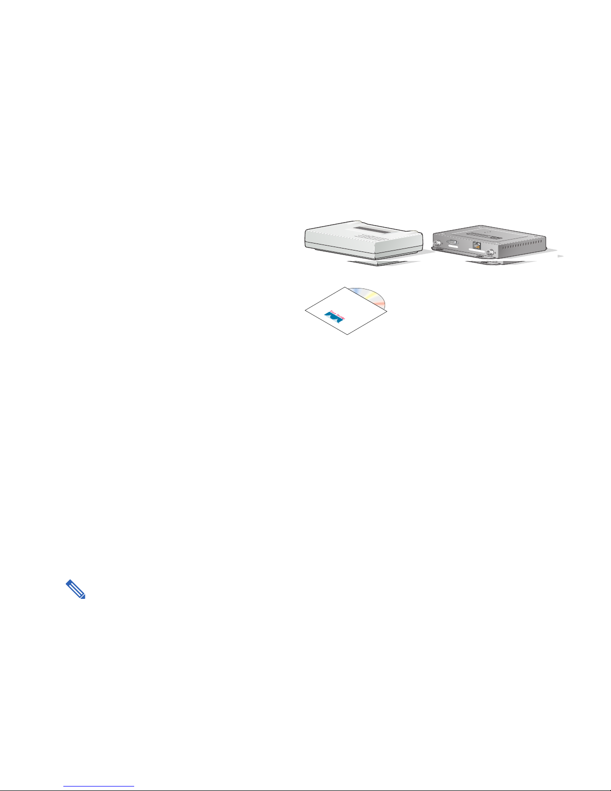
1 Take Out What You Need
Cisco Aironet 340 or 350 Seri es Access Point ( one
of the f o ll ow in g ):
• 340 or 350 series with a plastic case
Plastic case model Metal case model
Plastic case model Metal case model
TY
I
US
IV
AT
T
CT
S
Y
N
O A
IT
IO
V
DI
T
TI
IA
C
RA
C
T A
SO
E
AS
RN
E
H
ET
T
N
I
S
E
O
I
R
P
E
S
S
0
S
E
35
C
C
A
ET
N
S
S
E
L
Y
S
E
T
I
U
AIRO
V
R
T
I
A
I
T
T
C
S
CO
W
A
Y
N
T
I
O
O
I
I
V
I
D
T
CIS
T
A
A
I
C
R
C
A
O
T
S
E
S
N
A
R
E
H
T
E
LE
FT
LEFT
T
N
I
S
O
E
I
P
R
E
S
S
0
S
5
E
3
C
C
T
A
E
N
S
S
O
E
R
L
I
E
A
R
I
O
C
W
S
I
O
N
LIN
E
PO
W
E
ONLINE POWER ETHERNET
C
R
IG
H
T/P
R
IM
AR
Y
R
E
TH
ER
N
E
T
RIG
HT/PRIMARY
S
E
R
IA
L PO
R
T
SERIAL PO
RT
• 350 series with a me tal case
Cisco Aironet Access Point and Bridge CD with
documentation, online Help Files, and utilities
Additional Requirements
• A computer connected to the same network as the access point
• Category 5, straigh t-through Ethern et cable for co nnecting the acc ess point to the network and an
inline powe r sour ce
• The MAC address from the label on the bottom of the access point (for example: 00409625854c)
• The following information from your network system administrator:
–
The (case-sensitive) wireless service set identifier (SSID) for your radio network
–
A unique IP address for the a cce ss poi nt (for exam pl e: 17 2. 17. 25 5. 11 5) if no t conn ecte d to a
DHCP server
–
A default gateway and subnet mask if the access point is not on the same subnet as your PC
Note Plan to configure the access point before mounting it on a ceiling. Some steps,
such as those requiring a serial cable, are easier to perform if the access point is
accessible .
2
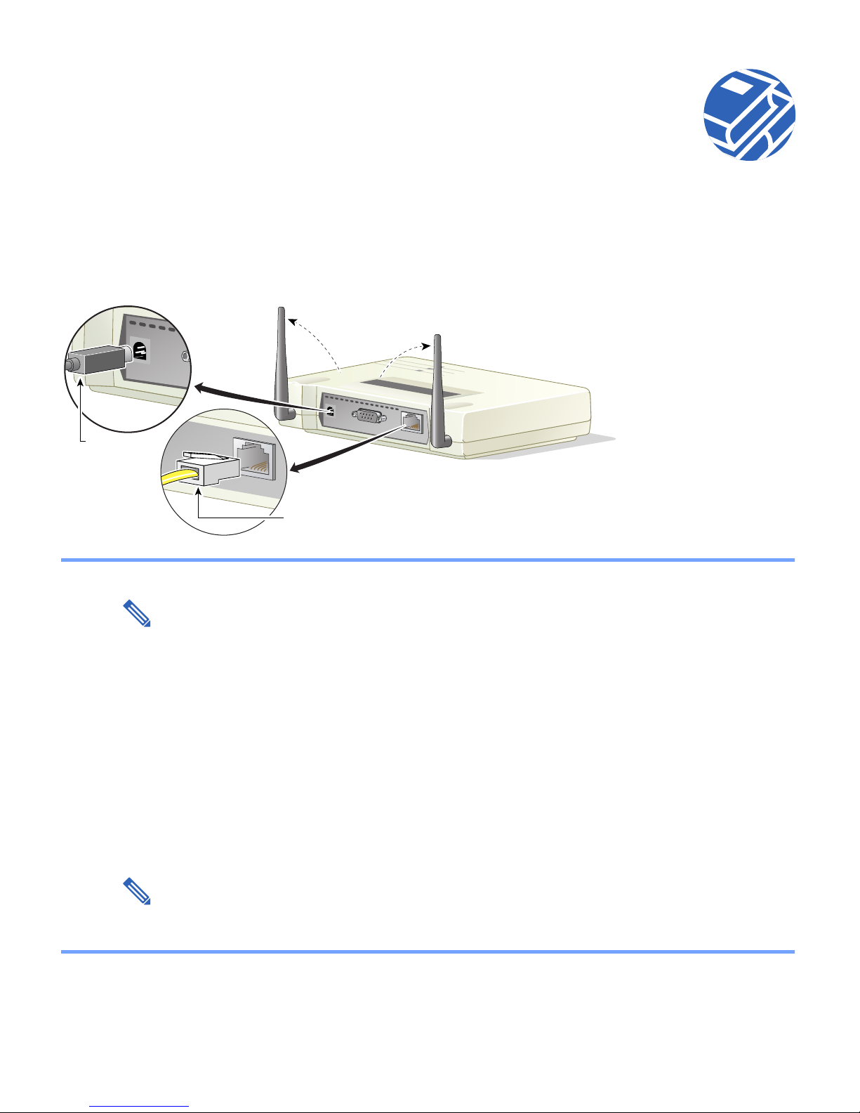
2 Connect and Powe r Up th e Acce ss Poin t
ETHERNET
5VDC
340 Series Access P oi nt s
5VDC
SERIAL
To wall outlet
To 10/100 Ethernet LAN
Step 1 Adjust the access point antennas.
ETHERNET
Note Antenna configurations vary depending upon the access point model.
For maximum range, make sure the access point antennas are perpendicular to the ground, no
matter where the acc ess poi nt will be mounte d.
If on a table or desk, point the antennas straight up.
If mounted on a wall, point the antennas straight up, even though if the access point is on its
side.
If mounted on the ceiling, point the antennas straight down.
Step 2 Connect the Ethernet cable from the wired 10/100 Ethernet LAN to the Ethernet connector
on the back of the access point.
Step 3 Plug the power pack connector into the power receptacle on the back of the access point.
Step 4 Plug the po we r pa c k i nto a wall out l et or power s t rip .
Note At start-up, all three LEDs on the to p of the ac cess p oint slo wly bl in k amber,
red, and green in sequence; the sequence takes a couple of minutes to complete.
Refer to the software configuration guide on the CD for LED descriptions.
3

2 Connect and Power Up the Access Point (continued)
350 Series Access P oi nt s
Note The following step s apply to 3 50 Series ac cess poi nts with met al or plast ic cases.
Option 1 Option 2 Option 3
Switch
S
Y
S
T
R
P
S
S
T
A
T
U
T
I
L
D
U
P
L
X
S
P
E
E
D
M
O
D
E
1
2
3
4
5
6
Switch with
inline power
7
8
1
0
B
a
s
e
-
9
T
/
1
0
0
B
a
1
s
e
0
T
X
1
1
1
2
1
3
1
4
1
5
1
6
1
7
1
8
(without inline power)
S
Y
S
T
1
R
P
S
2
3
4
S
T
A
T
5
U
T
I
L
D
U
P
L
X
6
S
P
E
E
D
7
8
1
0
B
a
s
e
-
9
T
M
O
D
E
C
a
t
a
l
y
s
1
t
9
2
9
5
0
S
E
2
R
I
0
E
S
2
1
2
2
1
2
0
3
0
B
a
s
e
F
X
2
4
2
3
2
4
/
1
0
0
B
a
1
s
e
0
T
X
1
1
1
2
1
3
1
4
1
5
1
6
1
7
1
8
C
a
t
a
l
y
s
1
t
9
2
9
5
0
S
E
2
R
I
0
E
S
2
1
2
2
1
2
0
3
0
B
a
s
e
F
X
2
4
2
3
2
4
S
Y
S
T
1
R
P
S
2
S
T
A
T
U
T
I
L
D
U
P
L
X
S
P
E
E
D
M
O
D
E
Inline Power
Patch Panel
Switch
(without inline power)
3
4
5
6
7
8
1
0
B
a
s
e
-
9
T
/
1
0
0
B
a
1
s
e
0
T
X
1
1
1
2
1
3
1
4
1
5
1
6
1
7
1
8
C
a
t
a
l
y
s
1
t
9
2
9
5
0
S
E
2
R
I
0
E
S
2
1
2
2
1
2
0
3
0
B
a
s
e
F
X
2
4
2
3
2
4
S
Y
S
T
R
P
S
S
T
A
T
U
T
I
L
D
U
P
L
X
S
P
E
E
D
M
O
D
E
Power injector
K
R
O
W
T
O
E
T
N
A
P
T
/
O
B
R
I
D
G
E
Power
cord
Universal
power supply
Access Point
Step 1 Adjust the access point antennas. Step 1 on page 3 of this guide provides guidelines for
positioning the antennas.
Step 2 Consult the drawing above and choose the power supply option you will use.
Step 3 Connect the Ethernet cable to the Ethernet connector on the back of the access point.
Connect the other end of the Ethernet cable to one of the following:
• A switch with inline power, such as a Cisco Catalyst 3524-PWR-XL
• An inline po wer sw itch pow er pane l, su ch as a Cisc o Cata lys t Inli ne Po wer Patc h Pane l
• The end of a Cisco Aironet power injector labeled To AP/Bridge and the end label ed To
Network to the 10/100 Ethernet LAN.
Caution The power injector is designe d for 35 0 seri es acce ss poi nts onl y. Using the power
injector with other Ethernet devices can damage the equipment.
4
 Loading...