

Page 1
1
Preface
This guide is designed to help you install an IEEE 802.11g-compliant radio
in a Cisco Aironet 1100 or 1200 Series Access Point. Detailed installation
and configuration information can be found in the following documents:
• Cisco Aironet 1100 Series Access Point Hardware Installation Guide
• Cisco Aironet 1200 Series Access Point Hardware Installation Guide
• Cisco IOS Software Configuration Guide for Cisco Aironet Access
Poi nt s
Note Before installing your 802.11g radio, make sure that you upgrade to
Cisco IOS Release 12.2(13)JA or later. If you do not upgrade, the
access point will continually reboot.
Documentation for the 1100 and 1200 series access points is available at
Cisco.com. Follow these links to access them:
http://cisco.com/en/US/products/hw/wireless/ps4570/tsd_products_support_
series_home.html
http://cisco.com/en/US/products/hw/wireless/ps430/tsd_products_support_s
eries_home.html
Page 2

2
Introduction
The Cisco Aironet IEEE 802.11g-compliant radio (hereafter called the
802.11g radio) is designed to upgrade 1100 and 1200 series access points to
IEEE 802.11g standards. The radio delivers 100 milliwatts (mW) maximum
transmit power at 1, 2, 5.5, and 11 megabits per second (Mbps) data rates and
30 mW maximum at all other data rates. The radio supports data rates of up
to 54 Mbps.
This guide provides instructions for installing or replacing an 802.11g radio
in an 1100 or 1200 series access point. The following operations summarize
the upgrade procedure:
1. Remove all cables and power connections from the access point.
2. Follow standard electrostatic discharge (ESD) procedures.
3. Place the access point on an ESD-protected work surface.
4. Open the access point’s radio access cover.
5. Install the new 802.11g radio card.
6. Close the access point’s radio access cover.
Page 3

3
Caution ESD can damage the Cisco Aironet client radio and the internal
components of the access point. It is recommended that the
802.11g radio upgrade procedures be performed by an
ESD-trained service technician at an ESD-protected
workstation.
Unpacking the Radio
Each 802.11g radio is shipped with the following items:
• This radio upgrade guide
• A product registration card
• A T-10 tamper-resistant Torx L-wrench (for 1200 series access points
only)
• Access point compliance labels (one for the 1100 and two for the 1200
series access points)
If anything is missing or damaged, contact your Cisco representative for
support.
Page 4

4
1100 Series Installation Instructions
Note Before installing your 802.11g radio, make sure that you upgrade to
Cisco IOS Release 12.2(13)JA or later. If you do not upgrade, the
access point will continually reboot.
Preparing the Access Point and Work Area
Follow these steps to prepare your access point and work area before
installing the 802.11g radio:
1. Remove all cables and power connections from the access point.
2. Place the access point on an ESD-protected work surface.
3. Remove all static-generating items from the work area, such as plastic
material, styrofoam cups, and other similar items.
4. Place the access point and the new 802.11g radio (in its antistatic bag)
on an antistatic work surface.
5. Discharge any static buildup on your body by touching a grounded
surface (antistatic work surface) before proceeding.
6. Follow standard ESD procedures during all phases of the process.
Page 5
5
Removing the Back Cover
Follow these steps to remove the access point’s back cover:
1. Position the access point so that its back cover is facing up.
Caution ESD can damage the internal access point components and the
802.11g radio if they are not handled properly.
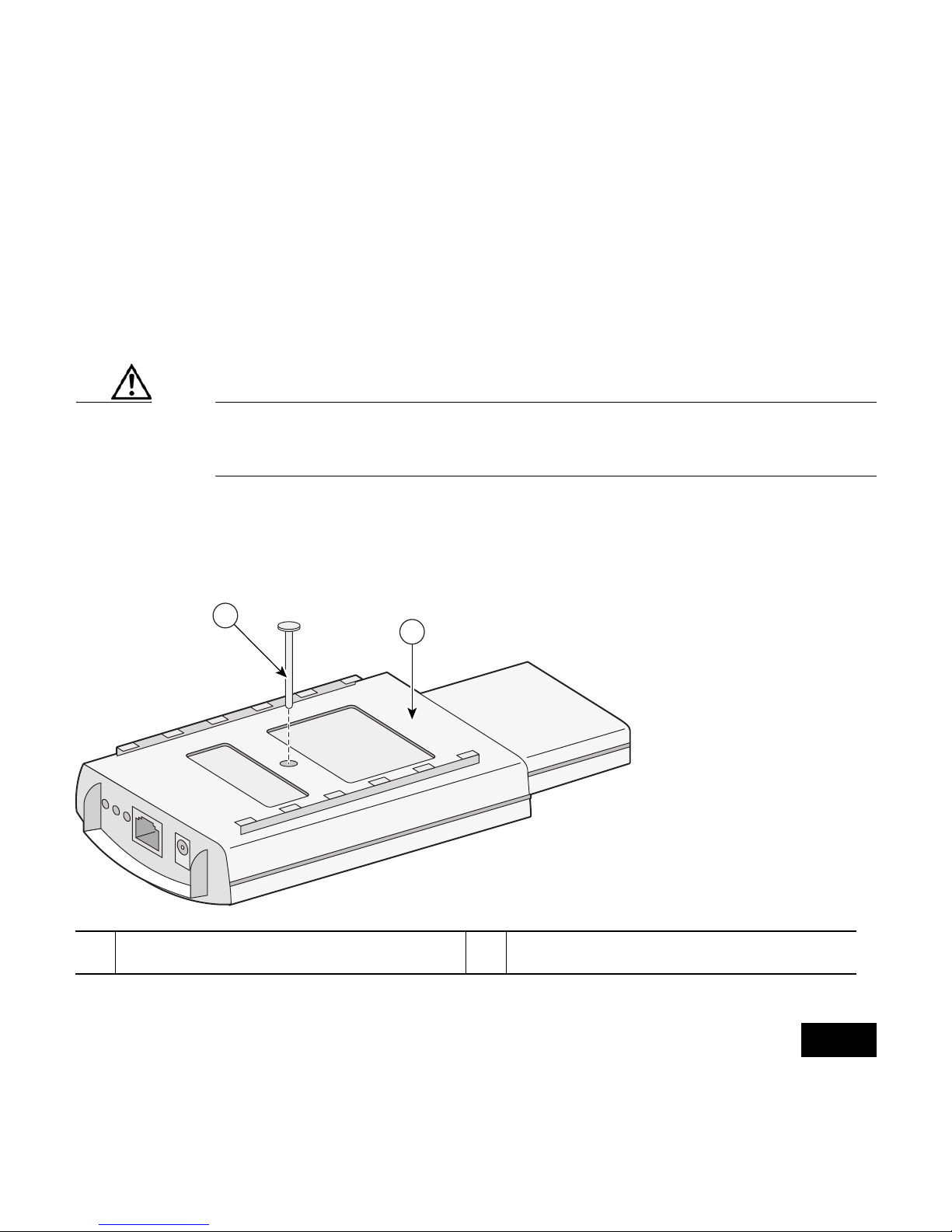
2. Remove the back-cover retaining screw using a Philips screwdriver as
shown in the following illustration.
1 Back cover screw 2 Back cover
95757
2
1
Page 6

6
3. Hold the front cover with one hand, and with the other hand gently slide
the back cover towards the connector end of the unit.
4. Gently lift the connector end of the back cover and remove the cover.
Removing the 2.4-GHz Radio
Follow these steps to remove the 2.4-GHz radio card from your access point:
1. Gently lift the top of the antenna card until it clears the plus-shaped (+)
support post as shown in the following illustration.
Page 7
7
2. Gently pull the antenna card to remove it from the notch in the support
bracket. Do not disconnect the antenna wire connectors.
3. Push the card-retaining clips (on each side of card) away from the radio
card (see the previous illustration). When released, the radio card springs
up. Do not disconnect the antenna wires.
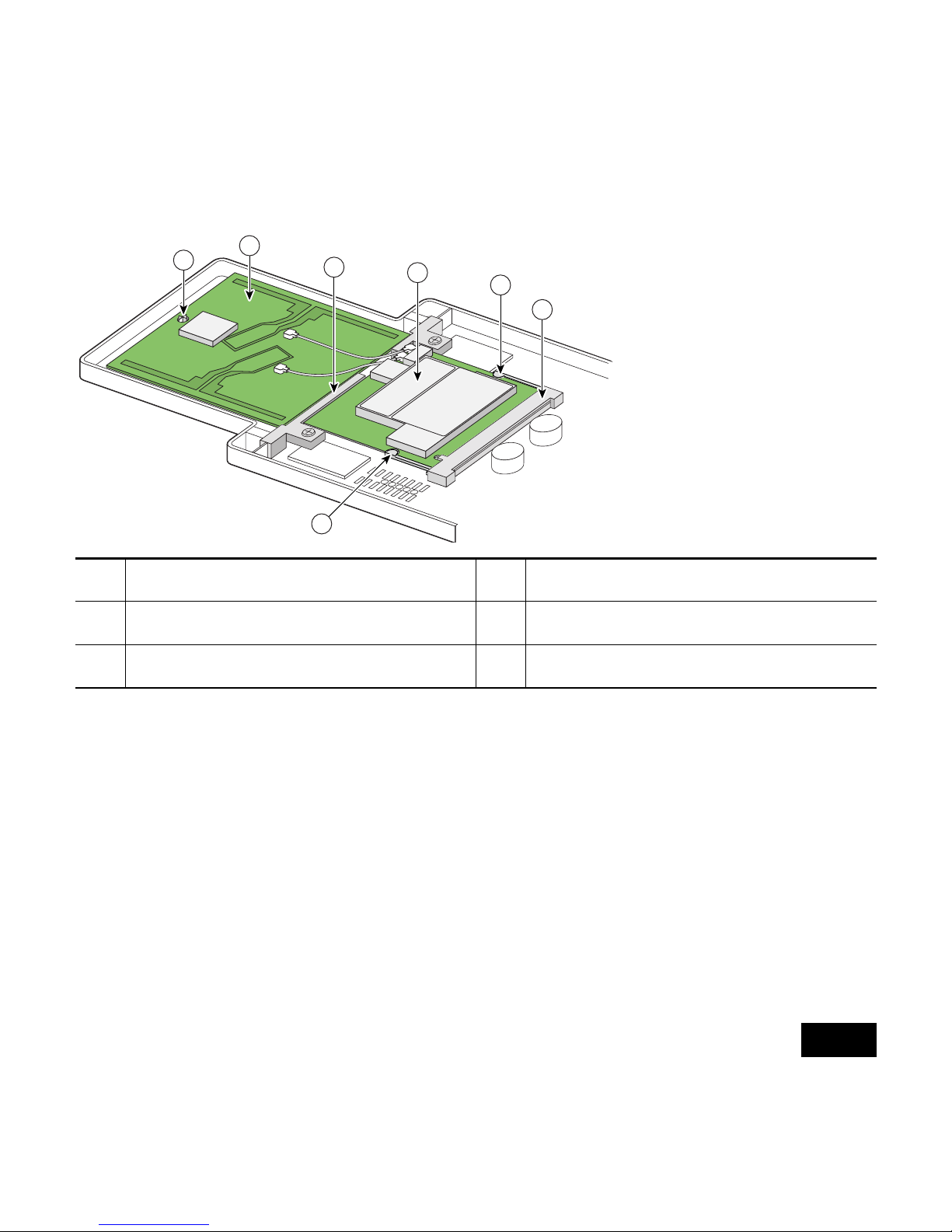
1 Plus-shaped (+) support post 4 2.4-Ghz radio card
2 Antenna card 5 Card retaining clips
3 Support bracket 6 Mini-PCI connector
95755
1
2
3
4
5
6
5
Page 8
8
Note If the radio card does not spring up, slightly loosen the support
bracket screws.
4. Remove the 2.4-GHz radio card from the mini-PCI connector by
performing the following operations:
a. Grasp the radio card only on the edges, being careful not to touch
components on the board or the gold connector pins.
b. Remove the 2.4-GHz card from the mini-PCI connector.
5. Place the radio card and antenna card on the ESD-protected work
surface.
Caution You can damage the connectors if you use long-nose pliers or
similar tools during the removal process. To avoid damaging the
antenna wire assemblies, remove them by hand.
6. Use your fingers to carefully remove the antenna wire connectors from
the 2.4-GHz radio card. Do not remove the antenna wire connectors from
the antenna board.
Page 9

9
Caution Do not pull the antenna wire to remove the connector from the
radio card. Damage to the wire and connector will result.
7. Place the 2.4-GHz radio card into an anti-static bag.
Note Do not put the antenna card in the anti-static bag. You will
connect it to the 802.11g radio card.
1 Antenna card 2 2.4-GHz radio card
95751
2
1
Page 10

10
Installing the 802.11g Radio
Follow these steps to install the 802.11g radio:
Caution ESD can damage the internal access point components and the
802.11g radio if they are not handled properly.
1. Carefully remove the 802.11g radio from its anti-static bag.
2. Grasp the card only on the edges, being careful not to touch components
on the board or the gold connector pins.
3. Place the radio on the anti-static work surface next to the antenna card.
Caution Do not use long-nose pliers or similar tools. To avoid damaging
the antenna wire assemblies, handle them by their connectors.
4. Use your fingers to carefully connect the antenna wire connectors to the
mating connectors on the 2.4-GHz radio card as shown in the illustration
on the following page.
Page 11
11
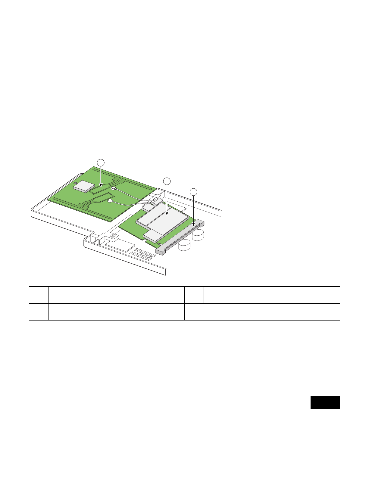
5. Insert the 802.11g radio card into the access point’s mini-PCI connector
by following these steps:
a. Tilt the radio card at approximately 20
o
to 30o so that its gold pins
are aligned with the mini-PCI connector as shown in the following
illustration.
b. Push the radio card into the mini-PCI connector until it is fully
seated (you will hear a slight click).
1 Antenna card 3 Mini-PCI connector
2 802.11g radio card
95753
3
2
1
Page 12

12
6. Hold the top of the antenna card with one hand and carefully push the
radio card down (towards the access point’s motherboard) with your
other hand until the card-retaining clips lock into the notches on the side
of the radio card (you will hear a click).
7. Insert the antenna card into the notch on the support bracket and gently
push until it is seated (see the following illustration).
8. Align the hole on the top of the antenna board with the support post and
gently push down until the board is fully seated on the support post.
1 Antenna card 3 Support bracket notch
2 Support post hole
95754
3
2
1
Page 13

13
9. Carefully position the antenna wires so that the metal connectors do not
touch each other.
10. Verify the following:
a. The card is properly secured with both retaining clips engaged.
b. The antenna board is properly secured.
c. The antenna connectors are not touching.
Caution Do not allow the antenna connectors to touch while power is
applied. If they are touching, carefully rotate them in opposite
directions until they are separated.
Replacing the Back Cover
Follow these steps to replace the back cover:
1. While holding the back cover near the connector end of the access point,
carefully place the latches on the antenna end into the detents on the end
of the front cover.
2. Release the back cover and with one finger gently push the connector
end of the back cover towards the antenna end. The back cover drops into
place and slides forward until it is fully seated.
Page 14

14
3. Use a Philips screwdriver to hand tighten the cover’s retaining screw.
4. Remove the backing paper from the 1100 series access point product
compliance label and carefully place the label over the existing label.
Configuring the 802.11g Radio
Refer to the following documents to configure the 802.11g radio:
• Cisco Aironet 1100 Series Access Point Hardware Installation Guide
• Cisco IOS Software Configuration Guide for Cisco Aironet Access
Poi nt s
These documents are available at Cisco.com. Follow the links on page 4 to
access them.
1200 Series Installation Instructions
Note Before installing your 802.11g radio, make sure that you upgrade to
Cisco IOS Release 12.2(13)JA or later. If you do not upgrade, the
access point will continually reboot.
Page 15

15
Caution ESD can damage the radio and the internal components of the
access point. It is recommended that the 802.11g radio upgrade
procedures be performed by an ESD-trained service technician
at an ESD-protected workstation.
Preparing the Access Point and Work Area
Follow these steps to prepare your access point and work area:
1. Remove all cables and power connections from the access point.
2. Place the access point on an ESD-protected work surface.
3. Remove all static-generating items from the work area, such as plastic
material, styrofoam cups, and other similar items.
4. Place the access point and the new 802.11g radio (in its antistatic bag)
on an antistatic work surface.
5. Discharge any static buildup on your body by touching a grounded
surface (antistatic work surface) before proceeding.
6. Follow standard ESD procedures during all phases of the process.
Page 16

16
Opening the Access Cover
Follow these steps to open the 2.4-GHz radio access cover:
1. Position the access point so that its bottom cover is facing up.
2. Use a T-10 tamper-resistant Torx L-wrench to remove the access cover
retaining fastener. See the illustration below.
If your access point was not configured with a 2.4-GHz radio, go to the next
section. If you are replacing an existing 2.4-GHz radio, go to the “Removing
a 2.4-GHz Radio” section on page 20.
1 Access cover screw
1
74458
Page 17

17
Removing the Blank Spacer Card
When your access point is not configured with a 2.4-GHz radio, it contains a
blank spacer card in the internal mini-PCI connector. You must remove the
blank spacer card prior to installing your 802.11g radio. If you are replacing
an existing 2.4-GHz radio, go to the “Removing a 2.4-GHz Radio” section on
page 20.
Caution Handle all components carefully and observe all ESD
precautions. The internal access point components can be
damaged by ESD if not handled properly.
Follow these steps to remove the blank spacer card from the mini-PCI
connector. It may be helpful to refer to the following illustration before you
proceed.
Page 18

18
Caution ESD can damage the internal access point components and the
802.11g radio if they are not handled properly.
1. Push the card-retaining clips (on each side of card) away from the card.
When released, the card will spring up as shown in the following
illustration.
1 Card-retaining clips
3
Antenna connector (black wire)
2 Antenna connector (white wire)
74248
1 3 12
Page 19

19
2. Carefully bend the card near the slots in opposite directions to provide
enough clearance to remove the antenna wires.
3. Remove the antenna wires from the slots.
Caution To avoid damaging the antenna wire assemblies, handle them by
their connectors.
4. Remove the card from the mini-PCI connector.
5. Discard the card.
6. Go to the “Installing the 802.11g Radio” section on page 10.
74249
Page 20

20
Removing a 2.4-GHz Radio
Follow these steps to remove a 2.4-GHz radio card from your access point.
Caution ESD can damage the internal access point components and the
2.4-GHz radio if they are not handled properly.
Caution Do not use long-nose pliers or similar tools. To avoid damaging
the antenna wire assemblies, handle them by their connectors.
Caution Do not pull the antenna wire to remove the connector from the
radio card. Damage to the wire and connector will result.
1. Use your fingers to carefully remove the antenna wire connectors from
the 2.4-GHz radio card.
Page 21

21
2. Remove the 2.4-GHz radio card from the mini-PCI connector by
performing the following steps:
a. Push the card-retaining clips (on each side of the card) away from
the card as shown in the following illustration. When released, the
card will spring up.
b. Grasp the card only by its edges, being careful not to touch
components on the card or the gold connector pins.
c. Remove the card from the mini-PCI connector.
1 Card retaining clips
MAIN AUX
74253
1 1
Page 22

22
3. Place the card in an anti-static bag.
Installing the 802.11g Radio Card
Follow these steps to install the 802.11g radio card:
1. Carefully remove the radio card from its anti-static bag.
2. Grasp the card by its edges, being careful not to touch components on
the card or the gold connector pins.
3. Carefully connect the black wire’s antenna connector to the radio card
antenna connector marked J2 (the connector on the outside of the card).
4. Carefully connect the white wire’s antenna connector to the radio card
antenna connector marked J1 (the connector on the inside of the card)
connector).
5. Insert the radio card into the access point’s mini-PCI connector by
following these steps:
a. Tilt the card at approximately 20 to 30 degrees so that its gold pins
are aligned with the mini-PCI connector.
b. Insert the card into the mini-PCI connector and gently push the card
until it is firmly seated as shown in the following illustration.
Page 23

23
1 Antenna connector
(black wire, J2)
3 Mini PCI connector
2 Antenna connector
(white wire, J1)
95829
3
2
1
Page 24

24
6. Carefully push the card down (towards the access point’s motherboard)
until the card-retaining clips lock into the notches on the side of the card
(you will hear a click when the retaining clips lock into the notches).
7. Verify the following:
a. The card is properly secured with both retaining clips engaged.
b. The black antenna wire is connected to outside connector (J2).
c. The white antenna wire is connected to the inside connector (J1).
d. The antenna connectors are not touching.
95827
Page 25

25
Caution Do not allow the antenna connectors to touch while power is
applied. If they are touching, carefully rotate them in opposite
directions until they are separated.
8. Reinstall the 2.4-GHz radio access cover and use a T-10 tamper-resistant
Torx L-wrench to tighten the cover’s retaining screw.
Attaching the Compliance Labels
There are three places on the 1200 series access point dedicated to
compliance labels, one for the product compliance label and two for the radio
compliance labels. The locations are shown in the following illustration.
Page 26

26
The product compliance label always occupies the top space (location 1). The
two spaces below (locations 2 and 3) contain the radio compliance labels.
Whether or not locations 2 or 3 contain labels depends on how your access
point is configured. For example, a dual-band access point could have two
radio compliance labels (one for each radio device installed), or it could have
only a product compliance label, depending on how it was ordered.
1 Product compliance label 3 Radio compliance label
2 Radio compliance label
1
2
3
103640
Page 27

27
Make sure your that access point has the correct labels after you install or
upgrade its radio configuration so that it will be in compliance with
regulations in your country.
Placing the Labels
The 802.11g radio upgrade kit ships with the following labels for the 1100
and 1200 series access points:
• 1100 series access point upgrade label (AIR-1121G-x-K9 UPGRADE)
• 1200 series product compliance label (AIR-AP1231G-x-K9)
• 1200 series radio compliance label (AIR-MP21G-x-K9)
The following table shows where to place the labels on your 1200 series
access point, based on the model you are upgrading. Follow these steps to
place the labels correctly:
1. Check the product compliance label to identify the model number of
your 1200 series access point.
Page 28

28
2. Use the matrix in the table to decide which labels to use and where to
place them on the access point.
3. Discard any labels you did not use.
Configuring the 802.11g Radio
Refer to the following documents to configure the 802.11g radio:
• Cisco Aironet 1200 Series Access Point Hardware Installation Guide
• Cisco IOS Software Configuration Guide for Cisco Aironet Access
Poi nt s
1200 Series
Model
AIR-MP21G-x-K9
Radio Compliance Label
AIR-AP1231G-x-K9 Product
Compliance Label
AIR-AP1200 Place over existing
AIR-MP20B-x-K9 radio
compliance label or
location 2 if no label exists.
—
AIR-AP1210
AIR-AP1220A
AIR-AP1230A
AIR-AP1220B — Place over existing
AIR-AP12xx-x-K9 product
compliance label.
AIR-AP1230B
Page 29

29
These documents are available at Cisco.com. Follow the steps on page 1 to
access them.
In Case of Difficulty
If you followed the instructions in previous sections of this guide, you should
have had no trouble getting your access point installed and running. However,
if you did experience difficulty, help is available from Cisco. Before
contacting Cisco, look for a solution to your problem in the troubleshooting
sections of the following documents:
• Cisco Aironet 1100 Series Access Point Hardware Installation Guide
• Cisco Aironet 1200 Series Access Point Hardware Installation Guide
• Cisco IOS Software Configuration Guide for Cisco Aironet Access
Poi nt s
The Technical Assistance Center contains additional troubleshooting
information. Follow this link to access this list on cisco.com:
http://cisco.com/en/US/support/index.html
Page 30

30
Safety Information
The FCC with its action in ET Docket 96-8 has adopted a safety standard for
human exposure to radio frequency (RF) electromagnetic energy emitted by
FCC certified equipment. When used with approved Cisco Aironet antennas,
Cisco Aironet products meet the uncontrolled environmental limits found in
OET-65 and ANSI C95.1, 1991. Proper installation of this radio according to
the instructions found in the Cisco Aironet 1100 Series Access Point
Hardware Installation Guide, and the Cisco Aironet 1200 Series Hardware
Installation Guide will result in user exposure that is substantially below the
FCC recommended limits.
• Do not touch or move antenna(s) while the unit is transmitting or
receiving.
• Do not hold any component containing a radio such that the antenna is
very close to or touching any exposed parts of the body, especially the
face and eyes, while transmitting.
• Do not operate the radio or attempt to transmit data unless the antenna is
connected; otherwise the radio may be damaged.
Page 31

31
• Antenna use:
High-gain, wall-mount, or mast-mount antennas are designed to be
professionally installed. Cisco recommends that you contact your
professional installer, VAR, or antenna manufacturer to obtain proper
installation requirements.
Warning
Do not operate a portable transmitter near unshielded blasting
caps or in an explosive environment unless it is a type
especially qualified for such use.
Warning
In order to comply with FCC RF exposure limits, dipole
antennas should be located at a minimum of 7.9 in.
(20 cm) from the body of all persons.
Compliance Information
This equipment has been tested and found to comply with the European
Telecommunications Standard ETS 300.328. This standard covers Wideband
Data Transmission Systems referred to in CEPT recommendation T/R 10.01.
Page 32

32
This type-accepted equipment is designed to provide reasonable protection
against harmful interference when the equipment is operated in a commercial
environment. this equipment generates, uses, and can radiate radio frequency
energy and, if not installed in accordance with the instruction manual, may
cause harmful interference to radio communications.
Cisco One-Year Limited Hardware
Warranty Terms
There are special terms applicable to your hardware warranty and various
services that you can use during the warranty period. Your formal Warranty
Statement, including the warranties and license agreements applicable to
Cisco software, is available on Cisco.com. Follow these steps to access and
download the Cisco Information Packet and your warranty and license
agreements from Cisco.com.
1. Launch your browser, and go to this URL:
http://www.cisco.com/univercd/cc/td/doc/es_inpck/cetrans.htm
The Warranties and License Agreements page appears.
Page 33

33
2. To read the Cisco Information Packet, follow these steps:
a. Click the Information Packet Number field, and make sure that
the part number 78-5235-03A0 is highlighted.
b. Select the language in which you would like to read the document.
c. Click Go.
The Cisco Limited Warranty and Software License page from the
Information Packet appears.
d. Read the document online, or click the PDF icon to download and
print the document in Adobe Portable Document Format (PDF).
Note You must have Adobe Acrobat Reader to view and print
PDF files. You can download the reader from Adobe’s
website: http://www.adobe.com.
Page 34

34
3. To read translated and localized warranty information about your
product, follow these steps:
a. Enter this part number in the Warranty Document Number field:
78-10747-01C0
b. Select the language in which you would like to view the document.
c. Click Go.
The Cisco warranty page appears.
d. Read the document online, or click the PDF icon to download and
print the document in Adobe Portable Document Format (PDF).
You can also contact the Cisco service and support website for assistance:
http://www.cisco.com/public/Support_root.shtml.
Duration of Hardware Warranty
One (1) Year
Replacement, Repair, or Refund Policy for Hardware
Cisco or its service center will use commercially reasonable efforts to ship a
replacement part within ten (10) working days after receipt of a Return
Materials Authorization (RMA) request. Actual delivery times can vary,
depending on the customer location.
Page 35

35
Cisco reserves the right to refund the purchase price as its exclusive warranty
remedy.
To Receive a Return Materials Authorization (RMA) Number
Contact the company from whom you purchased the product. If you
purchased the product directly from Cisco, contact your Cisco Sales and
Service Representative.
Complete the information below, and keep it for reference.
Company product purchased from
Company telephone number
Product model number
Product serial number
Maintenance contract number
 Loading...