

Page 1

Contents
Cisco Aironet 1300 Series Lightweight Outdoor
Access Point Mounting Instructions
June 2006
This document explains how to mount the Cisco Aironet 1300 Series Lightweight Outdoor Access Point
(Model number: AIR-LAP1310G) and contains the following sections:
• Introduction, page 2
• System Requirements, page 2
• Safety Warnings, page 3
• Safety Precautions, page 5
• Choosing a Mounting Location, page 7
• Mounting the Access Point, page 10
• Activating the Lightweight Access Point, page 32
• Using a DC Power Source, page 35
• Using a DC Power Source, page 35
• Related Documentation, page 38
• Locating the Product Serial Number, page 39
• Obtaining Documentation and Submitting a Service Request, page 40
Corporate Headquarters:
Cisco Systems, Inc., 170 West Tasman Drive, San Jose, CA 95134-1706 USA
Copyright © 2006 Cisco Systems, Inc. All rights reserved.
Page 2

Introduction
Introduction
The Cisco Aironet 1300 Series Lightweight Outdoor Access Point (hereafter called an access point) is
designed for indoor or outdoor installations, providing differing antenna gains as well as coverage
patterns. These access points are part of the Cisco Integrated Wireless Network Solution and require no
manual configuration before they are mounted. The access point is automatically configured by a Cisco
Wireless LAN Controller (herafter called a controller) using the Lightweight Access Point Protocol
(LWAPP).
Operating in the 2.4-GHz band (2.400 to 2.497 GHz), using the IEEE 802.11g standard, the access point
delivers 1 to 54 Mbps data rates without the need for a license. Using a controller, you can configure the
radio settings.
In the Cisco Centralized Wireless LAN architecture, access points operate in the lightweight mode (as
opposed to autonomous mode). The access points associate to a controller. The controller manages the
configuration, firmware, and control transactions such as 802.1x authentication. In addition, all wireless
traffic is tunneled through the controller.
LWAPP is an Internet Engineering Task Force (IETF) draft protocol that defines the control messaging
for setup and path authentication and run-time operations. LWAPP also defines the tunneling mechanism
for data traffic.
In an LWAPP environment, a lightweight access point discovers a controller by using LWAPP discovery
mechanisms and then sends it an LWAPP join request. The controller sends the access point an LWAPP
join response allowing the access point to join the controller. When the access point is joined, the access
point downloads its software if the versions on the access point and controller do not match. After an
access point joins a controller, you can reassign it to any controller on your network.
LWAPP secures the control communication between the access point and controller by means of a secure
key distribution, utilizing X.509 certificates on both the access point and controller.
The access point is available with an integrated antenna or with external antenna connectors. When using
a access point with an integrated antenna, you must choose a mounting location with a clear path to the
remote antenna and orient the access point so that the antenna is positioned for maximum signal strength.
The mounting brackets in the optional installation kit has adjustment slots that facilitate the positioning
process. When using a access point with an external antenna, mount the access point in a convenient
location near the external antenna. Each external antenna has its own mounting instructions.
Note To meet regulatory restrictions, the external antenna access point and the external antenna must be
professionally installed. The network administration or other IT professional responsible for installing and
configuring the unit is a suitable professional installer. Following installation, access to the unit should be
password protected by the network administrator to maintain regulatory compliance.
System Requirements
The access point system consists of a weather-proof unit, a power injector, a grounding block, and
optional external antennas. The access point and external antennas are typically mounted outdoors, the
grounding block is installed at the building entrance, and the power injector and the power module are
installed indoors. This document describes the access point mounting procedures only. For information
about other components, see the “Related Documentation” section on page 38.
Cisco Aironet 1300 Series Lightweight Outdoor Access Point Mounting Instructions
2
78-17634-01
Page 3

Package Contents
Each access point package contains these items:
• Access point unit (integrated antenna or external antenna configuration)
• Power injector (LR2) unit
• Power module and AC power cord
• Quick Start Guide: Cisco Aironet Lightweight Access Points
• Product mounting instructions (this document)
• Translated safety warnings document
• Read Me document
• Cisco product registration and documentation feedback cards
The optional roof mount kit contains these items:
• One roof-wall mount
• Two dual-coax cables [20 ft (6.1 m) and 50 ft (15.2 m)]
• Multi-function mount (consisting of a access point bracket and a mast bracket)
• Two tower clamps (U-bolts) with four nuts and washers
• Four bolts and washers for securing the access point bracket to the mast bracket
Package Contents
• Four bolts for securing the access point bracket to the unit
• Grounding block and mounting screws
• Ground lug for the access point, two hex nuts, and two washers
• Weatherproofing kit (consisting of Coax Seal and electrical joint compound)
The optional wall mount kit (for indoor use) contains these items:
• Wall mount bracket with 4 mounting bolts and washers
• Two sub-mini RG-59 coax cables (12 in. or 30.5 cm)
Safety Warnings
Translated versions of all the safety warnings are provided in the access point box and in Appendix A,
“Translated Safety Warnings” section of the Cisco Aironet 1300 Series Outdoor Access Point/Bridge
Hardware Installation Guide.
All Installations
Warning
This warning symbol means danger. You are in a situation that could cause bodily injury. Before
you work on any equipment, be aware of the hazards involved with electrical circuitry and be
familiar with standard practices for preventing accidents. (To see translations of the warnings
that appear in this publication, refer to the appendix “Translated Safety Warnings.”)
Statement 84
78-17634-01
Cisco Aironet 1300 Series Lightweight Outdoor Access Point Mounting Instructions
3
Page 4
Safety Warnings
Warning
Warning
Warning
Warning
Warning
Do not operate your wireless network device near unshielded blasting caps or in an explosive
environment unless the device has been modified to be especially qualified for such use.
Statement 245B
In order to comply with international radio frequency (RF) exposure limits, dish antennas should be
placed at a minimum of 8.7 inches (22 cm) from the bodies of all persons. Other antennas should be
placed a minimum of 7.9 inches (20 cm) from the bodies of all persons.
Do not work on the system or connect or disconnect cables during periods of lightning activity.
Statement 1001
This product relies on the building’s installation for short-circuit (overcurrent) protection. Ensure that
the protective device is rated not greater than: 15A
Statement 1005
This equipment must be grounded. Never defeat the ground conductor or operate the equipment in the
absence of a suitably installed ground conductor. Contact the appropriate electrical inspection
authority or an electrician if you are uncertain that suitable grounding is available.
Statement 246
Statement 1024
Warning
Warning
Ultimate disposal of this product should be handled according to all national laws and regulations.
Statement 1040
Do not locate the antenna near overhead power lines or other electric light or power circuits, or
where it can come into contact with such circuits. When installing the antenna, take extreme care
not to come into contact with such circuits, as they may cause serious injury or death. For proper
installation and grounding of the antenna, please refer to national and local codes (e.g. U.S.:NFPA 70,
National Electrical Code, Article 810, in Canada: Canadian Electrical Code, Section 54).
Statement 1052
Outdoor and DC Power Source Installations
The following warning applies to outdoor and DC power source installations:
Warning
Only trained and qualified personnel should be allowed to install, replace, or service this equipment.
Statement 1030
Cisco Aironet 1300 Series Lightweight Outdoor Access Point Mounting Instructions
4
78-17634-01
Page 5
DC Power Source Installations
The following warnings apply to DC power source installations:
Safety Precautions
Warning
Warning
A readily accessible two-poled disconnect device must be incorporated in the fixed wiring.
Statement 1022
Connect the unit only to DC power source that complies with the safety extra-low voltage (SELV)
requirements in IEC 60950 based safety standards.
Safety Precautions
Note To meet regulatory restrictions, the external antenna access point unit and the external antenna must be
professionally installed. The network administration or other IT professional responsible for installing and
configuring the unit is a suitable professional installer. Following installation, access to the unit should be
password protected by the network administrator to maintain regulatory compliance.
Each year hundreds of people are killed or injured when attempting to install an antenna. In many of
these cases, the victim is aware of the danger of electrocution, but does not take adequate steps to avoid
the hazard.
For your safety, and to help you properly install hardware, please read and follow these safety
precautions. They may save your life!
1. If you are installing an antenna for the first time, for your own safety as well as others, seek
assistance from a person with skills and knowledge related to the construction and operation of
electrical equipment and has received safety training on the hazards involved.
2. Keep safety as well as performance in mind when selecting your installation site Remember: electric
power lines and phone lines look alike. Always assume that overhead lines are very dangerous.
Statement 1033
3. Call your electric power company. Tell them your plans, and ask them to look at your proposed
installation. This is a reasonable request considering the danger.
4. Plan your installation carefully and completely before you begin. Successful raising of a mast or
tower is largely a matter of coordination. Assign each person a specific task, and ensure that they
know what to do and when to do it. Put one person in charge of the operation to issue instructions
and watch for signs of trouble.
5. When installing your antenna, remember:
a. Do not use a metal ladder.
b. Do not work on a wet or windy day.
c. Do dress properly—shoes with rubber soles and heels, gloves, long sleeved shirt or jacket.
6. If the assembly starts to fall, get away from it and let it fall. Remember, the antenna, mast, cable,
and metal guy wires are excellent conductors of electrical current and may touch power lines.
7. If any part of the antenna system comes in contact with a power line, don’t touch it or try to remove
it yourself. Call your local power company. They can remove it safely.
If an accident occurs with the power lines, call for qualified emergency help immediately.
78-17634-01
Cisco Aironet 1300 Series Lightweight Outdoor Access Point Mounting Instructions
5
Page 6
Safety Precautions
Typical Access Point Installation Components
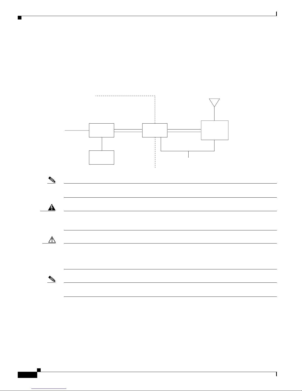
The access point is designed to be installed in an indoor or outdoor environment, typically on a wall,
tower, or tall building. A typical installation diagram is shown in Figure 1.
Figure 1 Typical Installation Diagram
Building
entrance
Indoor
Category 5
Ethernet
cable
Note Ground wires must comply with Sections 810 and 820 of the National Electrical Code and Section 54 of
Power
injector
Power
module
Grounding
Dual-coax
cables
block
Outdoor
Dual-coax
cables
Ground
(see note)
Integrated
or
external antenna
BR1310G or
LAP1310G
155881
the Canadian Electrical Code.
Warning
This equipment must be grounded. Never defeat the ground conductor or operate the equipment in the
absence of a suitably installed ground conductor. Contact the appropriate electrical inspection
authority or an electrician if you are uncertain that suitable grounding is available.
Statement 1024
Caution To ensure correct installation and grounding, install the access point in compliance with your local and
national electrical codes: National Fire Protection Association (NFPA) 70, National Electrical Code
(U.S.); Canadian Electrical Code, Part I, CSA 22.1 (Canada); and if local or national electrical codes are
not available, refer to IEC 364, Part 1 through 7 (other countries).
Note The ground block and grounding wire are not required when both the access point and the antenna are
mounted in a sheltered indoor environment.
Cisco Aironet 1300 Series Lightweight Outdoor Access Point Mounting Instructions
6
78-17634-01
Page 7
Deploying Lightweight Access Points on the Wireless Network
Deploying Lightweight Access Points on the Wireless Network
Prior to beginning the actual lightweight access point deployment, perform these tasks:
• Ensure that a site survey has been performed.
• Ensure that your network infrastructure devices are operational and properly configured.
• Ensure that your controllers are connected to switch trunk ports.
• Ensure that your switch is configured with untagged access ports for connecting your access points.
• Ensure that a DHCP server with Option 43 configured is reachable by your access points or
manually configure the controller information in the access point (for additional information, refer
to the Cisco Aironet 1300 Series Outdoor Access Point/Bridge Hardware Installation Guide).
Choosing a Mounting Location
Choosing a good mounting location for the access point is important because it affects the reliability of
the wireless link and maximum data rates it can support. The most important considerations are distance
between wireless devices and clearance from obstacles. The mounting location can be a wall, ceiling,
the top or side of a building, or on a tower providing a clear unobstructed line-of-sight to the wireless
devices.
With the integrated antenna access point configuration, the location must allow the access point to be
oriented in the proper direction.
With the external antenna access point configuration, the external antenna must be located within
line-of-sight of the wireless devices. The access point can be located in a convenient location that
minimizes the cable length to the antenna.
Note To meet regulatory restrictions, the external antenna access point and the external antenna must be
professionally installed. The network administration or other IT professional responsible for installing and
configuring the unit is a suitable professional installer. Following installation, access to the unit should be
password protected by the network administrator to maintain regulatory compliance.
Signal Path Distance
In an environment without obstacles in the signal path, the maximum operating distance depends
primarily on the type of antennas and the free space loss between the access point and wireless devices.
Make sure your proposed mounting site is within range of the wireless devices.
Note When operating as an access point, the maximum communication distance is approximately 1 mile.
78-17634-01
Cisco Aironet 1300 Series Lightweight Outdoor Access Point Mounting Instructions
7
Page 8

Choosing a Mounting Location
Antenna Polarization
The integrated antenna radiates and receives vertically polarized radio signals. Polarization helps reduce
interference because the antenna tends to reject cross-polarized signals from other sources.
Note For the multi-point links, Cisco recommends that you use vertical polarization on all antennas; however,
on point-to-point links you can also use horizontal polarization on both ends of the link. To operate
correctly, the antennas at each end of the wireless link should have the same polarization.
The following lightweight access point antenna is vertically polarized:
• 5.2-dBi omni-directional antennas
The following lightweight access point antennas can be vertically or horizontally polarized depending
on their mounting orientation:
• 10-dBi a yagi antennas
• 9-dBi patch wall-mount antenna
Signal Path Clearance
A radio beam travels from the access point to another in a straight line. Therefore, the path between the
antennas must be free of major obstacles. The effects of obstacles and terrain, both along and near the
path, have a significant bearing on the propagation of radio signals and can cause both interference and
signal cancellation.
When choosing a site, consider the effects of the following common obstacles:
• Trees and large plants
A tree directly in the path can totally block the signal. With clearance above the trees there are
usually no secondary effects, but you should allow for future tree growth.
• Man-made obstacles
A large round container such as a gas storage reservoir or water tower that is partially in the path
causes some blocking. These obstacles may also reflect some energy, which can interfere with other
receivers. Square or rectangular objects in or near the path have rectangular surfaces that can block
and diffract signals over and around them.
• Internal building obstacles
When mounting the access point in an indoor location, the signal can be block obstructions, such as
walls, office cublicles, steel file cabinets, metal ducts, and metal shelving. These obstacles can also
reflect some energy, which can interfere with radio receivers.
For tower installations, you may need to climb the tower to the proposed mounting location to verify a
clear path to the other site. If trees are in the line of signal propagation, leave extra clearance above
them for future growth into the signal path.
Cisco Aironet 1300 Series Lightweight Outdoor Access Point Mounting Instructions
8
78-17634-01
Page 9

Physical Site Inspection
Perform a visual inspection of the site to ascertain and document the physical characteristics of the site
and to ensure that all requirements are met for the proper installation and operation of the system.
Contact Information and Access Permissions
Make sure the following general requirements are met before beginning the installation:
• Validate customer-provided information, such as site contact names and telephone numbers.
• Examine the building (tenant) lease to verify or establish building roof or tower rights. If available,
use layout drawings to evaluate the feasibility of modifications or special permits that might be
necessary.
• For a tower-mounted installation, find out if the owner, operator, or landlord requires a professional
or certified tower climber to do the work.
Physical Site
Make sure the following physical site requirements are met before beginning the installation:
• Identify the roof area, wall, or tower for mounting the access point.
Choosing a Mounting Location
Cable Routes
Caution To prevent damage to the access point or power injector, connect all coax cables from the power injector
• Determine the access area, such as a stairway or a ladder.
• Identify existing equipment installations and assess the condition of proposed towers or mounting
structures.
• Assess environmental conditions, such as temperature, ventilation, and humidity.
Make sure the following cable route requirements are met before beginning the installation:
• Identify cable routes, building entry points, and any special routing or support requirements
(conduits, bracing, cable trays, safety structures, and so on). Make sure the total cable length
between the access point and the power injector is no greater than 100 meters.
• Identify necessary floor, roof, or wall penetrations and specify the locations.
• Document existing grounding system and connection requirements for new equipment.
• Refer to these electrical codes for your local regulations:
–
NFPA 70 (US National Electrical Code)
–
Canadian Electrical Code, Part1, CSA 22.1
–
IEC 364, Part 1 through 7 for other countries
to the access point and connect the power jack to the power injector before applying power.
78-17634-01
Cisco Aironet 1300 Series Lightweight Outdoor Access Point Mounting Instructions
9
Page 10

Mounting the Access Point
Lightning Arrestor
In outdoor antenna installations, your antenna and access point can be damaged by surges that develop
on the antenna and cable from close lightning strikes. You can use a lightning arrestor (such as
AIR-ACC-3354) to help protect your access point system from static electricity and lightning-induced
surges; however, an arrestor will not prevent damage from a direct lightning hit.
A lightning arrestor is a 50-ohm transmission line with a gas discharge tube positioned between the
center conductor and ground. This gas discharge tube changes from an open circuit to a short circuit
almost instantly (100 nanoseconds) in the presence of voltage and energy surges, providing a path to
ground for the energy surge.
A lightning arrestor should be installed between your outdoor antenna and the access point. You should
connect a 6 AWG copper wire from the arrestor to a good earth ground.
Mounting the Access Point
This section describes how to mount the access point and position the antenna and contains the following
topics:
• Required Tools and Fasteners, page 11
• Window Mounting, page 12
• Wall or Ceiling Mounting Bracket, page 13
• Rooftop or Wall Mount, page 15
• Tower Mount, page 18
• Mast Mount, page 21
• Applying Coax Seal Tape, page 24
• Assembling the Mounting Hardware, page 26
• Attaching the Mounting Bracket, page 29
• Rooftop Support or Small Mast Diameters, page 30
• Mounting the Access Point on a Support, page 31
Personnel installing the access point must understand wireless installation techniques and grounding
methods.
Note To meet regulatory restrictions, the external antenna access point unit and the external antenna must be
professionally installed. The network administration or other IT professional responsible for installing and
configuring the unit is a suitable professional installer. Following installation, access to the unit should be
password protected by the network administrator to maintain regulatory compliance.
These procedures focus on general mounting and cable-routing topics. For information about assembling
the mounting hardware, see the “Assembling the Mounting Hardware” section on page 26.
Cisco Aironet 1300 Series Lightweight Outdoor Access Point Mounting Instructions
10
78-17634-01
Page 11

Required Tools and Fasteners
This section describes the required tools, cables, and fasteners.
Tools
Mounting the access point requires the following tools:
• 7-mm, 8-mm, and 13-mm wrench or socket for mult-function mount
• Two 7/16 wrenches or sockets for roof mount
• Crimping tool for F-connectors that accommodates RG6/U cable (http://www.tessco.com)
• Crimping tool for ground lug, Panduit CT-1004 or equivalent (http://onlinecatalog.panduit.com)
You may also require tools for user-supplied hardware or fasteners.
Cables
Cisco recommends the following types of coaxial cable for the access point-to-power injector
connections:
Mounting the Access Point
Fasteners
Table 1 Recommended Coaxial Cable Types
Cable Type Belden Part # Times Fiber Part # Channel Master Part #
RG6 9077 2360-T660-VB or
2560-T690-VB
RG59/U 1426A 02345-T5953-VB 9540
RG59/U 1505A 02183-T5967-VB –
RG11/U 8213 02362-T1153-VB –
Identify requirements for special hardware or fasteners that are not supplied in the installation kit. For
example, it might be necessary to secure the access point to an unusually large-diameter pipe or
odd-shaped structural member that the supplied mounting bracket cannot accommodate.
The rooftop or wall mounting bracket requires the following user-provided fasteners:
• Wooden structure—four 1/4 x 1 inch (minimum) lag bolts
• Hollow walls—four 1/4-20 x 2 3/4 molly anchors
• Concrete structure—four 1/4 x 1 3/4 inch (minimum) bolts with concrete anchors
The wall or ceiling mounting bracket requires the following user-provided fasteners:
• Wooden structure—three 1/4 x 1 inch (minimum) lag bolts
9539
• Hollow walls—three 1/4-20 x 2 3/4 molly anchors
• Concrete structure—three 1/4 x 1 3/4 inch (minimum) bolts with concrete anchors
Note For the user-provided fasteners, you must use the appropriate drill size recommended by your fastener
vendor.
78-17634-01
Cisco Aironet 1300 Series Lightweight Outdoor Access Point Mounting Instructions
11
Page 12

Mounting the Access Point
Pole or tower mounting requires U bolts that fit the pole or mast in use. One source is One source is
McMaster-Carr’s web site.
Document all the necessary tools, parts, brackets, hardware and accessories that are required for the
installation and make sure you have them all before starting.
Window Mounting
When you are deploying a wireless access point link through a window, the window glass can introduce
significant signal loss. Typical losses range from 5 to 15 dB per window, depending upon the type of
glass. Deployment planning should take this extra loss into account conservatively when planning
antenna gains and power settings. A thorough site survey is critical for deployments that require
penetration through windows.
For additional information on a window mounting bracket, refer to the following URL:
http://www.terra-wave.com/shop/above-ceiling-tile-mounting-bracket-with-adjustable-height-p-665.ht
ml
General Guidelines
Many types of window glass allow radio signals to pass through easily while some types greatly restrict
radio signals. These are some general guidelines for operating through window glass:
• Avoid glass with metallic content or metallic coatings
• Avoid glass with conductive gas between the panes
• Avoid glass with embedded wire
• Select windows at roughly the same height at both ends
• Select windows with the least thickness
• Ensure that radio signal quality tests are conducted through the glass before finalizing the site
selection
Mounting Above a Suspended Ceiling
The access point can be mounted above a suspended ceiling in environmental air space using the wall or
ceiling mounting bracket (refer to the “Wall or Ceiling Mounting Bracket” section on page 13).
Note The access point and power injector have adequate fire resistance and low smoke-producing
characteristics to make them suitable for operation in a building's environmental air space (such as above
suspended ceilings) in accordance with Section 300-22(C) of the National Electrical Code (NEC).
Note When mounting the access point or power injector in a building's environmental air space, you must use
coax and Ethernet cables suitable for operation in environmental air space in accordance with Section
300-22(C) of the National Electrical Code (NEC).
Note The power module is not rated for mounting above suspended ceilings.
Cisco Aironet 1300 Series Lightweight Outdoor Access Point Mounting Instructions
12
78-17634-01
Page 13

Wall or Ceiling Mounting Bracket
The access point supports a wall or ceiling mounting bracket that can be used only with the external
antenna access point unit (see Figure 2). The bracket can be used indoors only.
Installing the access point on a wall or ceiling includes the following subtasks:
1. Mounting the unit
2. Routing the cables (normal)
3. Activating the link
Figure 2 Access Point with Wall or Ceiling Mounting Bracket
Mounting the Access Point
Mounting the Access Point
To mount the external antenna access point unit using the wall or ceiling mounting bracket, follow these
steps:
Step 1 Choose a mounting location for the access point. For more information, see “Choosing a Mounting
Location” section on page 7.
Step 2 Find a solid mounting position for the mounting bracket, such as a stud or main building member on a
building wall or ceiling. It may be necessary to utilize a stud finder to find a wooden structural member.
Step 3 Place the mounting bracket on the access point as shown in Figure 2 and snap into position. The bracket
has an opening that corresponds to the shape of the access point with a flat cut-out segment that
corresponds to the access point connector area.
117142
Note The bracket support feet must be positioned towards the front of the access point.
78-17634-01
Cisco Aironet 1300 Series Lightweight Outdoor Access Point Mounting Instructions
13
Page 14

Mounting the Access Point
Step 4 Mount the access point using the following user-provided hardware:
• Wooden structure—three 1/4 x 1 inch (minimum) lag bolts
• Hollow walls—three 1/4-20 x 2 3/4 molly anchors
• Concrete structure—three 1/4 x 1 inch (minimum) bolts with concrete anchors
Note Examine the structure to ensure that the mounting location is not deteriorating or weak. You are
responsible for ensuring that the mounting location can adequately support the access point.
Step 5 Tighten the bolts to secure the access point mounting bracket to the wall or ceiling.
Mounting the Power Injector on the Access Point
When using the wall or ceiling mounting bracket, you can mount the power injector directly on the
access point mounting lugs (see Figure 3) using the hardware included with the bracket.
Note When mounted together, the access point and power injector must be mounted in a sheltered indoor
environment.
Figure 3 Mounting the Power Injector on the Access Point
117145
The following hardware used to mount the power injector on the access point is supplied with the wall
or ceiling mounting bracket kit:
• Four hex head bolts with serrated flange (M6x1x10 mm)
• Four washers
Cisco Aironet 1300 Series Lightweight Outdoor Access Point Mounting Instructions
14
78-17634-01
Page 15

• Two short sub-mini RG-59 coax cables (12 in.)
Tighten the bolts to secure the power injector to the access point. Torque bolts to 6 to 8 ft-lbs.
Connecting the Cables
This procedure explains how to connect the cables and how to ground the access point:
Step 1 Connect the two short coax cables to the power injector and to the access point.
Caution To prevent damage to the access point or power injector, connect all coax cables from the
Step 2 Find the building's grounding electrode system and then connect the access point ground lug to it using
6 AWG copper wire. Use a crimping tool to crimp the wire to the ground lug. For more information about
attaching the ground lug to the access point, see Step 3 and Step 4 in the “Attaching the Housing Bracket
to the Access Point” section on page 28. See Figure 11 for the ground lug location.
Mounting the Access Point
power injector to the access point and connect the power jack to the power injector before
applying power.
Warning
This equipment must be grounded. Never defeat the ground conductor or operate the equipment in the
absence of a suitably installed ground conductor. Contact the appropriate electrical inspection
authority or an electrician if you are uncertain that suitable grounding is available.
Note The grounding block and grounding wire are not required when mounting both the access point
and the antenna in a sheltered indoor environment.
Rooftop or Wall Mount
The mounting kit has a rooftop mounting bracket that is suitable for flat roofs, sloping roofs, and outdoor
walls. Mounting the access point on a rooftop or wall includes the following subtasks:
1. Mounting the access point
2. Routing the cables
This warning applies to outdoor installations.
Warning
Only trained and qualified personnel should be allowed to install, replace, or service this equipment.
Statement 1030
Statement 1024
78-17634-01
Cisco Aironet 1300 Series Lightweight Outdoor Access Point Mounting Instructions
15
Page 16

Mounting the Access Point
Mounting the Access Point
To mount the access point on a rooftop or wall, follow these steps:
Step 1 Choose a mounting location for the access point. If you are using the integrated antenna, the mounting
location must provide a clear signal path to the remote access point. For more information, see
“Choosing a Mounting Location” section on page 7.
Step 2 Find a solid mounting position for the base bracket, such as a stud or main building member on a roof
or external wall. It may be necessary to utilize a stud finder to find wooden structural members.
Step 3 Assemble the rooftop mount. For more information, see the “Assembling the Rooftop Mount” section
on page 26.
Step 4 Mount the rooftop bracket at the mounting location using the following user-provided hardware:
• Wooden structure—four 1/4 x 2 inch (minimum) lag bolts
• Concrete structure—four 1/4 x 1 inch (minimum) bolts with concrete anchors
Figure 4 shows the rooftop mast assembly:
Figure 4 Roof-Mount Mast
Make sure that the mounting pole is vertical. You can rotate the foot of the bracket to adjust the vertical
position for wall or sloped-roof mounting locations.
Step 5 Tighten the bolts to secure the mounting pole to the mounting foot. Torque nuts to 12 to 14 ft-lb.
Step 6 Attach the access point to the vertical section of the pole using the supplied brackets and hardware. For
more information, see the “Assembling the Mounting Hardware” section on page 26.
Cisco Aironet 1300 Series Lightweight Outdoor Access Point Mounting Instructions
16
88750
78-17634-01
Page 17

Figure 5 shows the access point mounted on the rooftop mast:
Figure 5 Roof-Mount Assembly
1515
0
IS
H
T
E
ID
S
P
U
Mounting the Access Point
Step 7
Routing the Cables
Step 1 Unspool two 75-ohm cables the full length from the access point to the grounding block, laying them
Step 2 Install F-connectors on the access point end of each cable and connect the cables to the access point. For
Step 3 Dress the cables along the path from the access point to the grounding block. Secure the cables as you
117146
Point the antenna as accurately as possible in the direction of the remote antenna. The integrated antenna
is correctly positioned when the flat face of the radome faces the remote antenna.
This procedure explains how to route the power injector cables from the access point to a grounding
block. The grounding block should be installed at the building entry point.
To route and connect cables, follow these steps:
out straight without kinks. Do not cut the cables until you know the total required length between the
access point and grounding block.
outdoor locations, the cables should slope downward from the access point connectors so that moisture
runs away from the access point during rainstorms. If necessary, form drip loops near the connectors.
go using UV-stabilized Ty-Wraps or equivalent fasteners.
78-17634-01
Cisco Aironet 1300 Series Lightweight Outdoor Access Point Mounting Instructions
17
Page 18

Mounting the Access Point
Step 4 Cut the cables to length, install F-connectors on the ends, and connect them to the grounding block.
Caution To prevent damage to the access point or power injector, connect all coax cables from the
Note The grounding block must be connected to the building's grounding electrode system by
Step 5 Find the building's grounding electrode system and then connect the access point ground lug to it using
6 AWG copper wire. Use a crimping tool to crimp the wire to the ground lug. For more information about
attaching the ground lug to the access point, see Step 3 and Step 4 in the “Attaching the Housing Bracket
to the Access Point” section on page 28. See Figure 11 for the ground lug location.
Caution To ensure correct installation and grounding, install the access point in compliance with your
power injector to the access point and connect the power jack to the power injector before
applying power.
14 AWG copper wire or larger.
local and national electrical codes: National Fire Protection Association (NFPA) 70, National
Electrical Code (U.S.); Canadian Electrical Code, Part I, CSA 22.1 (Canada); and if local or
national electrical codes are not available, refer to IEC 364, Part I through Part 7 (other
countries).
Step 6 For outdoor locations, weather seal all coaxial connectors by wrapping them with the sealant tape
Tower Mount
Warning
Note Local code may require grounding of the rooftop mount.
provided with the installation kit. For more information, see the “Applying Coax Seal Tape” section on
page 24.
A professional installer must install the access point on a tower. A professional installer has skills and
knowledge related to the construction, operation, and installation of electrical equipment and has
received safety training on the hazards involved.
Installing the access point on a tower includes the following subtasks:
1. Mounting the access point
2. Routing the cables (normal or lightning protected)
3. Activating the link
This warning applies to outdoor access point installations.
Only trained and qualified personnel should be allowed to install, replace, or service this equipment.
Statement 1030
Cisco Aironet 1300 Series Lightweight Outdoor Access Point Mounting Instructions
18
78-17634-01
Page 19
Mounting the Access Point
To mount the access point on a tower, follow these steps:
Step 1 Choose a mounting location on the tower for the access point. If you are using the integrated antenna,
the mounting location must provide a clear signal path to the remote access point. For more information,
see “Choosing a Mounting Location” section on page 7.
Step 2 Find a suitable mounting support or install a mounting pole for the access point. The mounting bracket
accommodates poles from 1.25 to 2.75 inches (30.5 to 69.9 mm) in diameter; the supplied U bolts fit
1.25 to 1.75-inch poles only. You can find this type of hardware at http://www.rohnnet.com.
Step 3 Hoist the access point assembly to the mounting location. The mounting brackets have openings for
hoisting the unit.
Step 4 Attach the access point to the mounting pole using appropriate hardware (see Figure 6). For more
information, see the “Assembling the Mounting Hardware” section on page 26.
Step 5 Point the antenna as accurately as possible in the direction of the remote antenna. The integrated antenna
is correctly positioned when the flat face of the radome faces the remote antenna.
Mounting the Access Point
Warning
Caution To ensure correct installation and grounding, install the access point in compliance with your
This equipment must be grounded. Never defeat the ground conductor or operate the
equipment in the absence of a suitably installed ground conductor. Contact the appropriate
electrical inspection authority or an electrician if you are uncertain that suitable grounding
is available.
Statement 1024
local and national electrical codes: National Fire Protection Association (NFPA) 70, National
Electrical Code (U.S.); Canadian Electrical Code, Part I, CSA 22.1 (Canada); and if local or
national electrical codes are not available, refer to IEC 364, Part I through Part 7 (other
countries).
Note Local code may require grounding of the tower mount.
Step 6 Find the building's grounding electrode system and then connect the access point ground lug to it using
6 AWG copper wire. Use a crimping tool to crimp the wire to the ground lug. For more information about
attaching the ground lug to the access point, see Step 3 and Step 4 in the “Attaching the Housing Bracket
to the Access Point” section on page 28. See Figure 11 for the ground lug location.
Routing the Cables for Lightning Protection
In areas where lightning strikes are common and when the access point is mounted high on the tower,
ground the shields of the RG6 coaxial cables to the tower at regular intervals. This precaution helps
protect the access point and power injector from lightning damage. The recommended spacing between
grounds is 200 ft (60 m). In areas of especially high lightning risk, space the grounds even closer.
78-17634-01
Cisco Aironet 1300 Series Lightweight Outdoor Access Point Mounting Instructions
19
Page 20

Mounting the Access Point
Note Be sure to comply with the tower owner's policies and local codes. Drilling into tower structures,
damaging painted surfaces, or other alterations can affect the tower's long-term integrity.
To route and connect cables for lightning protection follow these steps:
Step 1 Mount grounding blocks to the tower at intervals of about 200 ft (60 m) along the cable route. Make sure
each grounding block makes good electrical (metal-to-metal) contact with the tower.
Step 2 Cut cable segments for each interval and preinstall F-connectors.
Step 3 Secure the cable segments along the route using UV-stabilized Ty-Wraps or equivalent fasteners.
Step 4 Connect all cable segments. For outdoor installations, use drip loops at each point to assure that water
runs away from the connectors.
Step 5 Proceed to the following procedure, starting from the lowest grounding block instead of from the access
point.
Routing the Cables Normally
To route and connect power injector cables normally, follow these steps:
Step 1 Unspool two 75-ohm cables the full length of the tower, laying them out straight without kinks. Do not
cut the cables until you know the total required length between the access point and grounding block.
Step 2 Install F-connectors on the cable ends before climbing the tower.
Step 3 Tie a rope near the end of the two cables, and secure it using black electrical tape. Make sure that the
connectors do not support any cable weight.
Step 4 From the tower, use the rope to pull the cables up from the ground, making sure that they pass along a
tower member where they can be securely fastened. Leave ample cable for a service loop at the access
point.
Step 5 Secure the cables to the tower and along the route to the building grounding block using UV-stabilized
Ty-Wraps or equivalent fasteners.
Warning
This equipment must be grounded. Never defeat the ground conductor or operate the
equipment in the absence of a suitably installed ground conductor. Contact the appropriate
electrical inspection authority or an electrician if you are uncertain that suitable grounding
is available.
Statement 1024
Caution To prevent damage to the access point or power injector, connect all coax cables from the
power injector to the access point and connect the power jack to the power injector before
applying power.
Note The grounding block must be connected to the building's grounding system by 14 AWG copper
wire or larger.
Cisco Aironet 1300 Series Lightweight Outdoor Access Point Mounting Instructions
20
78-17634-01
Page 21

Step 6 Connect the cables to the access point (or lowest grounding block on the tower). The cables should slope
Step 7 Cut the cables to length, install F-connectors on the ends, and connect them to the grounding block.
Step 8 Weather seal all coaxial connectors by wrapping them with the sealant tape provided with the installation
Mast Mount
Mounting the Access Point
downward so that moisture runs away from the connectors during rainstorms. If necessary, form drip
loops near the connectors.
kit. For more information, see the “Applying Coax Seal Tape” section on page 24.
Mounting the access point on a tall mast makes antenna positioning difficult because you cannot view
the access point LEDs or adjust the antenna vertically. If possible, use a mast short enough so that you
can reach the access point from a step ladder or other support. Otherwise, you may need to take down
the mast to adjust the antenna position.
Mounting the access point on a mast includes the following subtasks:
1. Preparing the mast
2. Mounting the access point
3. Routing mast cables
This warning applies to outdoor installations.
Warning
Only trained and qualified personnel should be allowed to install, replace, or service this equipment.
Statement 1030
Preparing the Mast
To prepare the mast, follow these steps:
Step 1 Choose a mounting location for the mast. For more information, see the “Choosing a Mounting
Location” section on page 7.
Step 2 Find a solid mounting position on the building for the mast mounting bracket, such as a stud or main
building member on a roof or external wall. Use a stud finder, if necessary, to find wooden structural
members.
Step 3 Find the mast-mounting hardware and guy wire.
Step 4 Find and install the guy line mounting points. A minimum of three, preferably four, guy lines should
hold the mast in position.
Step 5 Measure the length of the guy lines by attaching the lines to the mast at their mounting point and
unspooling them to the attachment points.
4. Raising the mast and connecting cables
Step 6 Raise the mast to its vertical position and temporarily secure all guy lines to their mounting points.
Step 7 Ensure that the mast is vertical using a level on two sides (90 degrees apart) of the pole. Adjust guy lines
as necessary and note their attachment points.
78-17634-01
Cisco Aironet 1300 Series Lightweight Outdoor Access Point Mounting Instructions
21
Page 22

Mounting the Access Point
Step 8 Take down the mast.
Mounting the Access Point
To mount the access point on the mast, follow these steps:
Step 1 Attach the access point near the top of the mast.
If the mast is the same diameter as the rooftop support, you can use the supplied hardware. The mounting
brackets accommodate a small mast (see Figure 6). For more information, see the “Assembling the
Mounting Hardware” section on page 26.
Figure 6 Access Point Attached to a Small Mounting Pole
1515
1
1
0
IS
H
T
E
ID
S
P
U
2
117144
1 U bolt (2 supplied) 2 Small mast, 1.25 to 2.5 inches
(30.5 to 63.5 mm) in diameter
Step 2 Connect the ground lug on the access point to the mast using #6 gauge wire. Use a crimping tool to secure
the wire to the ground lug. Use a mast clamp or tapped screws into the mast for the mast connections.
Cisco Aironet 1300 Series Lightweight Outdoor Access Point Mounting Instructions
22
78-17634-01
Page 23
Routing Mast Cables
To route and connect cables, follow these steps:
Step 1 Unspool two 75-ohm cables the full length from the access point to the grounding block, laying them
out straight without kinks. Do not cut the cables until you know the total required length between access
point and grounding block.
Step 2 Install F-connectors on the access point end of each cable and connect the cables to the access point. The
cables should slope downward from the access point connectors (when the mast is raised) so that
moisture runs away from the access point during rainstorms. If necessary, form drip loops near the
connector.
Step 3 Secure the cables to the mast using UV-stabilized Ty-Wraps or equivalent fasteners.
Step 4 Weather seal all coaxial connectors by wrapping them with the sealant tape provided with the installation
kit. For more information, see the “Applying Coax Seal Tape” section on page 24.
Raising the Mast and Connecting Cables
Mounting the Access Point
To raise the mast and connect cables, follow these steps:
Step 1 Tilt the mast assembly to the upright position, set the mast in its mounting base clamp, orient the antenna
in the direction of the remote antenna, and secure the guy wires.
Step 2 Tighten the mast clamp so the mast is secure but so that it can be rotated for final adjustments in
positioning.
Warning
Caution To ensure correct installation and grounding, install the access point in compliance with your
This equipment must be grounded. Never defeat the ground conductor or operate the
equipment in the absence of a suitably installed ground conductor. Contact the appropriate
electrical inspection authority or an electrician if you are uncertain that suitable grounding
is available.
Statement 1024
local and national electrical codes: National Fire Protection Association (NFPA) 70, National
Electrical Code (U.S.); Canadian Electrical Code, Part I, CSA 22.1 (Canada); and if local or
national electrical codes are not available, refer to IEC 364, Part I through Part 7 (other
countries).
Step 3 Find the building's grounding electrode system and then connect the mast to it using 6 AWG copper wire.
For more information about attaching the ground lug to the access point, see Step 3 and Step 4 in the
“Attaching the Housing Bracket to the Access Point” section on page 28. See Figure 11 for the ground
lug location.
Step 4 Dress the cables along the path from the mast to the grounding block. Secure the cables as you go using
UV-stabilized Ty-Wraps or equivalent fasteners.
78-17634-01
Cisco Aironet 1300 Series Lightweight Outdoor Access Point Mounting Instructions
23
Page 24
Mounting the Access Point
Caution To prevent damage to the access point or power injector, connect all coax cables from the
power injector to the access point and connect the power jack to the power injector before
applying power.
Note The grounding block must be connected to the building's grounding system by # 14 AWG copper
wire or larger.
Step 5 Cut the cables to length, install F-connectors on the ends, and connect them to the grounding block.
Step 6 Weather seal all coaxial connectors by wrapping them with the sealant tape provided with the installation
kit. For more information, see the “Applying Coax Seal Tape” section on page 24.
Applying Coax Seal Tape
You must weather seal all coaxial connections using the Coax-Seal tape provided in the mounting kit.
Coax connections that are not properly sealed permit moisture to enter the connection, which leads to
performance degradation or link problems.
The following connectors must be weather sealed:
• F-connectors, located at the access point and each grounding block.
• R-TNC antenna connectors, when using the access point with an external antenna.
Note Do not use only plastic electrical tape on the connectors because it deteriorates during long-term
exposure to ultraviolet light and extreme weather.
To apply Coax Seal, follow these steps:
Step 1 Make sure that the coaxial cables, connectors, and the connector area are clean and dry.
Step 2 Peel the paper backing from a 10-inch length of Coax-Seal tape.
Step 3 Wrap each access point connector with the tape, starting at the coaxial cable, extending across the
connector body, and finishing close the access point or grounding block. Overlap each turn at least 50
percent so there is a double thickness over all areas (see Figure 8).
Note To simplify removal of the connector in the future, you can first wrap the connector with a good
grade of electrical tape before applying the Coax-Seal. You should tightly wrap the electrical
tape and overlap each turn at least 25 percent for full coverage.
Cisco Aironet 1300 Series Lightweight Outdoor Access Point Mounting Instructions
24
78-17634-01
Page 25

Figure 7 Coax Seal Tape Application
Mounting the Access Point
117058
Step 4
Using your fingers, mold and form the Coax-Seal around the cable and connector to form a smooth
surface. Make sure to squeeze out any air pockets (see Figure 8).
Figure 8 Coax Seal Tape after Forming into Shape
117057
78-17634-01
Cisco Aironet 1300 Series Lightweight Outdoor Access Point Mounting Instructions
25
Page 26

Mounting the Access Point
Step 5 Visually inspect the seal to make sure the entire connector area is completely covered. If you find gaps,
apply additional Coax-Seal over the existing material and then mold it to shape.
Step 6 Repeat this procedure for each coaxial connection on the access point and grounding blocks.
Assembling the Mounting Hardware
The access point mounting hardware can accommodate tower, mast, or rooftop installations. The
mounting hardware comprises the following key parts:
• Housing brackets
• Mounting bracket
• Rooftop mount or wall mounting bracket
Assembling the Rooftop Mount
The rooftop mount or wall mounting bracket (see Figure 9) is used to mount your access point to a flat
horizontal or vertical surface, such as a building roof or wall. You must assemble the rooftop mount
before you can use it. Skip this section if you are not using the rooftop mount.
To assemble the mount, follow the instructions below:
Step 1 Place a washer on the long flanged hex bolt.
Step 2 Place the end of the mast pipe with the bolt holes into the base plate (see Figure 9).
Cisco Aironet 1300 Series Lightweight Outdoor Access Point Mounting Instructions
26
78-17634-01
Page 27

Figure 9 Rooftop Support Bolt Locations
Mounting the Access Point
1
2
3
88949
1 Long flanged hex bolt 3 Carriage bolt
2 Carriage bolt
Step 3 Align the holes in the mast pipe with the holes in the base plate.
Step 4 Insert the long flanged hex bolt and washer into the upper holes on the base plate and through the mast
pipe (see Figure 9).
Step 5 Place a washer and hex nut on the end of the long flanged hex bolt and hand-tighten.
Step 6 Position the mast pipe and base plate as shown in Figure 9.
Step 7 Align the lower square hole in the mast pipe with the semi-circular cut-out on the base plate.
Step 8 Place the carriage bolt into the square hole on the inside of the mast pipe.
Step 9 Place a washer and hex nut on the end of the carriage bolt and hand-tighten.
Step 10 Repeat Steps 8 and 9 for the other square hole.
You have completed the assembly of your rooftop or wall mount. To mount your rooftop or wall mount,
please refer the “Mounting the Access Point” section on page 10.
78-17634-01
Cisco Aironet 1300 Series Lightweight Outdoor Access Point Mounting Instructions
27
Page 28

Mounting the Access Point
Attaching the Housing Bracket to the Access Point
To attach the housing bracket to the access point, follow these steps:
Step 1 Before attempting to attach the housing bracket, refer to Figure 10.
Figure 10 Housing Bracket Attachment
2
2
3
1
3
2
2
117143
1 Housing bracket 3 Hang pin
2 Hex bolt with serrated flange 4
Step 2
Step 3 Apply a thin layer of electrical joint compound to the access point at the ground lug location (See
Attach the housing bracket to the housing using four hex bolts. Torque bolts to 8 to 10 ft-lb.
Figure 11).
Cisco Aironet 1300 Series Lightweight Outdoor Access Point Mounting Instructions
28
78-17634-01
Page 29

Figure 11 Ground Lug Attachment Point
1
1
1 Threaded mounting studs for the ground lug
Mounting the Access Point
117141
Step 4
Attach the supplied ground lug to the two threaded mounting studs on the access point using the two
supplied locking Hex nuts. Torque the nuts to 10 to 12 in-lb.
Note Do not remove the two factory installed lock nuts on the mounting studs.
Note After you install the access point on its support, connect this ground to the building ground using
6 AWG wire.
Attaching the Mounting Bracket
The mounting bracket is suitable for rooftop, mast, or tower supports. How you attach the mounting
bracket to the support depends on the mast diameter, as follows:
Mast Type Mast Diameter Mast Attachment
Rooftop support
or small mast
1.25 to 2.75 in.
(30.5 to 69.9 mm)
Attach the mast to the mounting bracket between the
bracket and access point (see Figure 12)
78-17634-01
Cisco Aironet 1300 Series Lightweight Outdoor Access Point Mounting Instructions
29
Page 30

Mounting the Access Point
Rooftop Support or Small Mast Diameters
Use this procedure to attach the mounting bracket to the rooftop support or to a mast with a diameter
between 1.25 and 2.75 inches (30.5 to 69.9 mm). For masts other than the rooftop support, use U bolts
that fit the mast in use.
To attach the mounting bracket to the rooftop support or small mast, follow these steps:
Step 1 Position the mounting bracket next to the mounting pole so that the arrow on the bracket points up.
Figure 12 Mounting Bracket Assembly for Rooftop Support
1
15
0
15
2
6
MOUNT
UP
3
4
5
91495
1 U bolt 4 Hex nut
2 Mounting bracket 5 Roof mounting mast
3 Flat washer 6 Hang pin slot
Step 2 Attach the mounting bracket to the mast using two U bolts and four nuts and washers.
Note If you are using the integrated antenna, loosely tighten the U bolts so you can adjust the access
point horizontally for antenna positioning.
Cisco Aironet 1300 Series Lightweight Outdoor Access Point Mounting Instructions
30
78-17634-01
Page 31

Mounting the Access Point on a Support
This warning applies to outdoor installations:
Mounting the Access Point
Warning
Only trained and qualified personnel should be allowed to install, replace, or service this equipment.
Statement 1030
To attach the access point to a support, follow these steps:
Step 1 Mount the housing bracket to the mounting bracket by sliding the hang pins on the housing bracket into
the hang pin slots on the mounting bracket. The connectors should face downward (See Figure 13).
Figure 13 Mounting the Access Point to the Support
1515
0
1
IS
H
T
E
ID
S
P
U
1
117140
1 Hex bolt with serrated flange and washer (4 locations)
Step 2
Secure the housing bracket to the support bracket with four hex bolts and flat washers.
Note If you are using the integrated antenna, loosely tighten the U bolts so you can adjust the access
point horizontally for antenna positioning.
Step 3 Roughly position the integrated antenna by pointing the flat face of the access point toward the site of
the remote access point.
Step 4 After aligning the antenna, tighten all mounting bolts to 6 to 10 ft-lbs.
78-17634-01
Cisco Aironet 1300 Series Lightweight Outdoor Access Point Mounting Instructions
31
Page 32

Activating the Lightweight Access Point
Activating the Lightweight Access Point
Prior to activating the lightweight access points, ensure the following:
• Your network infrastructure devices are operational and properly configured.
• Your controllers are connected to switch trunk ports.
• Your switch is configured with untagged access ports for connecting your access points.
• A DHCP server with Option 43 configured is reachable by your access points or that the access
points are configured with controller information. For additonal information, refer to the Cisco
Aironet 1300 Series Outdoor Access Point/Bridge Hardware Installation Guide and the Cisco
Wireless LAN Controller Configuration Guide.
To activate an access point, follow these steps:
Step 1 Ensure that the dual coax cables are connected to the access point connectors.
Step 2 Ensure that proper grounding is connected to the access point.
Step 3 Ensure that lightning arrestors are connected for externally mounted access points.
Step 4 Ensure that the dual coax cables are connected to the power injector.
Step 5 Connect the power plug from the power module to the power injector.
Step 6 Connect an Ethernet LAN cable to the power injector.
Step 7 Plug the power module AC cable into an AC power outlet.
Manually Configuring Controller Information Using the
Lightweight Access Point CLI
In a new installation, when your lightweight access point is unable to reach a DHCP server, you can
manually configure needed controller information using the access point CLI.
Note The CLI commands in this section can be used only on a lightweight access point that is not associated
to a controller.
The static information configured with the CLI commands are used by the access point to connect with
a controller. After connecting with the controller, the controller reconfigures the access point with new
controller settings, however, the static access point IP address and Gateway IP address continue to be
used.
Cisco Aironet 1300 Series Lightweight Outdoor Access Point Mounting Instructions
32
78-17634-01
Page 33

Manually Configuring Controller Information Using the Lightweight Access Point CLI
Connecting to the Console Serial Port
To access the access point CLI interface, you can connect a PC to the power injector console serial port
using a DB-9 to RJ-45 serial cable.
Note On lightweight access points, you can only use the CLI interface when the access point is not associated
with a controller.
Follow these steps to open the CLI by connecting to the console serial port:
Step 1 Connect a nine-pin, female DB-9 to RJ-45 serial cable to the RJ-45 serial port on the power injector and
to the COM port on your PC. Figure 14 shows the power injector’s console serial port connector.
Figure 14 Console Serial Port Connector
POWER INJECTOR
CISCO AIRONET
117188
1
1 Console serial port connector (RJ-45 connector)
Note The Cisco part number for the DB-9 to RJ-45 serial cable is AIR-CONCAB1200. Browse to
http://www.cisco.com/go/marketplace to order a serial cable.
Step 2 Set up a terminal emulator to communicate with the access point. Use the following settings for the
terminal emulator connection: 9600 baud, 8 data bits, no parity, 1 stop bit, and no flow control.
Step 3 When the terminal emulator is activated, press Enter. An Enter Network Password window appears.
Step 4 Enter your username in the User Name field. The default username is Cisco.
Step 5 Enter the access point password in the Password field and press Enter. The default password is Cisco.
When the CLI activates, you can enter CLI commands.
78-17634-01
Cisco Aironet 1300 Series Lightweight Outdoor Access Point Mounting Instructions
33
Page 34

Manually Configuring Controller Information Using the Lightweight Access Point CLI
Configuring Controller Information
Use these Exec mode CLI commands to manually configure controller information on a new access
point:
lwapp ap ip address <IP address> <subnet mask>
lwapp ip default-gateway IP-address
lwapp controller ip address IP-address
lwapp ap hostname name
Where name is the access point name on the controller.
Note The default Enable password is Cisco.
Clearing Manually Entered Controller Information
When you need to move your access point to a different location in your network, you must clear the
manually entered controller information to allow your access point to associate with a different
controller.
Note This command requires the controller-configured Enable password to enter the CLI EXEC mode.
You can use these EXEC mode CLI commands to clear or remove the manually entered controller
information:
clear lwapp ap ip address
clear lwapp ip default-gateway
clear lwapp controller ip address
clear lwapp ap hostname
Manually Resetting the Lightweight Access Point to Defaults
You can manually reset your lightweight access point to default settings using this EXEC mode CLI
command:
clear lwapp private-config
Note This command requires the controller configured Enable password to enter the CLI EXEC mode.
Cisco Aironet 1300 Series Lightweight Outdoor Access Point Mounting Instructions
34
78-17634-01
Page 35

Using a DC Power Source
The access point can be powered from a DC power source using the optional LR2T power injector. The
following sections identify the maximum cable length that can be supported in these environments using
a few different coax cable types.
When choosing cables other than those shown in the following examples, take care to ensure that the RF
characteristics of the new cable meets or exceeds the RF characteristics of the cable examples up to
500 MHz. Also, be sure to use good quality cable connectors and grounding blocks such that the DC
resistive losses associated with all the connections “combined” are less than 0.2 ohms.
Using a DC Power Source
Warning
Note The Cisco Aironet Power Injector LR2T must be used with a DC power source.
Only trained and qualified personnel should be allowed to install, replace, or service this equipment.
Statement 1030
Electrical Load-Dump Protection
In battery power systems, a load-dump occurs when the battery is disconnected from the charging system
while supplying power, and the devices connected to the battery system must dissipate the very large
energy transient that is produced. For example, this situation can occur if the battery cables are loose or
in a service shop where a mechanic accidentally removes the battery cable while the engine is running.
In order to comply with the transportation vehicle load-dump requirements specified in SAE 1211 and
SAE1455 standards, you must use an external load-dump protection device. This device must be
connected to the power cable between your vehicle’s battery system and the power injector.
You must install an external load-dump protection device in all vehicle systems that can experience a
load-dump and that are supplying +24 VDC (or above) to the power injector.
For more information on load-dump protection devices, refer to Appendix I of the Cisco Aironet 1300
Series Outdoor Access Point/Bridge Hardware Installation Guide.
DC Power Cable and Connector
When using a DC power source, you are responsible for providing the power cable, fuse, and power
connector used for the power injector. The power injector requires an external power supply capable of
supplying 13 W of power at a typical vehicle battery voltage: +12 VDC, +24 VDC, or +40 VDC. For the
power cable, the positive voltage is connected to the center pin and the return is connected to the external
barrel of the power plug.
Warning
Warning
78-17634-01
A readily accessible two-poled disconnect device must be incorporated in the fixed wiring.
Statement 1022
Connect the unit only to DC power source that complies with the safety extra-low voltage (SELV)
requirements in IEC 60950 based safety standards.
Statement 1033
Cisco Aironet 1300 Series Lightweight Outdoor Access Point Mounting Instructions
35
Page 36
Using a DC Power Source
Caution Only a qualified electrician or service person should make and install the power cable with in-line fuse
Caution To prevent damage to the access point or power injector, connect all coax cables from the power injector
supplying DC-power to the power injector.
to the access point and connect the power jack to the power injector before applying power.
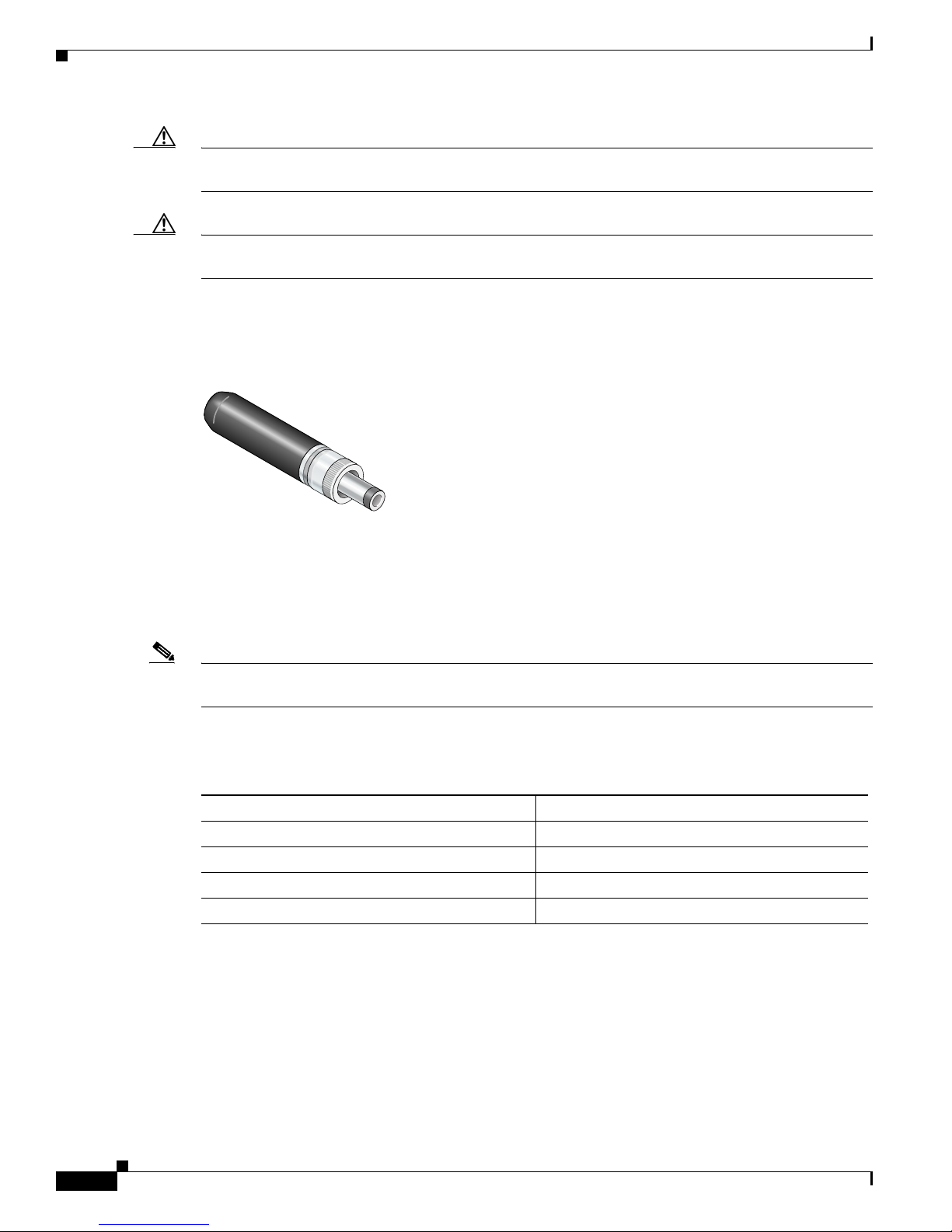
The power plug has a screw-on cap to secure the power cable to the power injector. The mating power
plug is a Switchcraft 760K (see Figure 15).
Figure 15 Power Plug
117002
Inline Power Fuse
When you mount the access point in a vehicle, an inline power fuse must be used in the positive (+)
power line going to the power injector.
Note The inline power fuse must be listed and certified to the appropriate safety standards for the country
where the access point is installed.
Table 2 provides the inline power fuse requirements:
Table 2 Inline Power Fuse Requirement
Vehicle Power Source Inline Fuse (Slow-blow)
+12 VDC 1.7 A
+24 VDC 600 mA
+37.5 VDC 360 mA
+40 VDC 335 mA
Cisco Aironet 1300 Series Lightweight Outdoor Access Point Mounting Instructions
36
78-17634-01
Page 37
Coax Cable Lengths
In some DC power source environments, the voltage supplied to the power injector can vary depending
on the operating load. The following sections indicate the maximum coax cable lengths that can be
supported using several typical coax cables.
To determine the maximum coax cable length supported for a different coax cable, you can use the coax
cable length calculator utility at this URL:
http://www.cisco.com/go/aironet/coax_length_utility
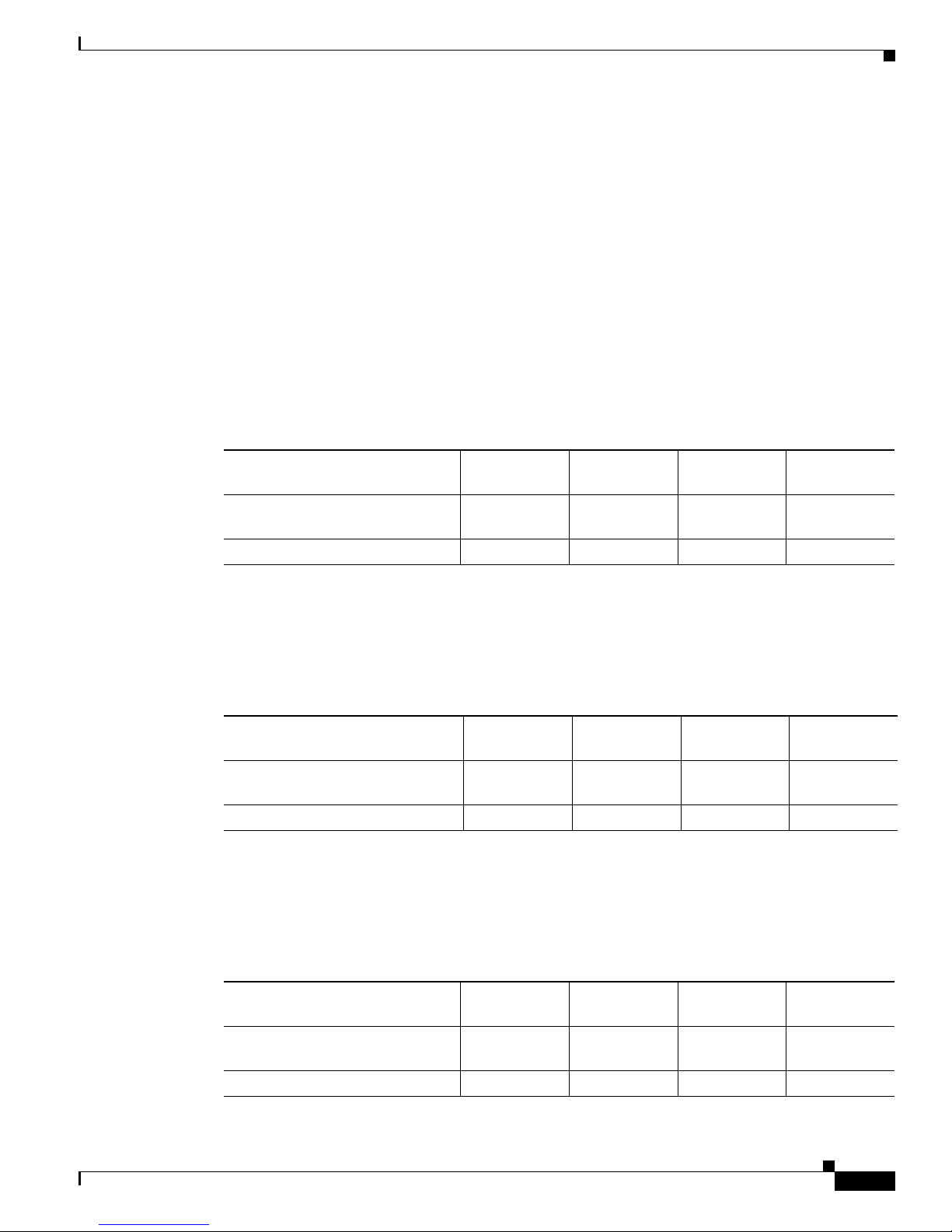
Environments Providing 12 VDC Power
Table 3 indicates the maximum cable length that can be supported by several coax cables when using a
+12 VDC power source.
Table 3 Maximum Cable Length for Environments Providing 12 VDC Power
Using a DC Power Source
Cable Parameters
Minimum voltage available at
power injector (volts)
Maximum cable length (meters) 7.5 22 20 75
Environments Providing 24 VDC Power
Table 4 indicates the maximum cable length that can be supported by several coax cables when using a
+24 VDC power source.
Table 4 Maximum Cable Length for Environments Providing 24 VDC Power
Parameters
Minimum voltage available at
power injector (volts)
Maximum cable length (meters) 100 100 100 100
Environments Providing 40 VDC Power
Table 5 indicates the maximum cable lengths that can be supported by several coax cables when using a
+40 VDC power source.
RG-6/U
Belden 9077
10 10 10 10
RG-6/U
Belden 9077
18 18 18 18
RG-59/U
Belden 1426A
RG-59/U
Belden 1426A
RG-59/U
Belden 1505A
RG-59/U
Belden 1505A
RG-11/U
Belden 8213
RG-11/U
Belden 8213
Table 5 Maximum Cable Lengths for Environments Providing 40 VDC Power
Cable Parameters
Minimum voltage available at
power injector (volts)
Maximum cable length (meters) 100 100 100 100
78-17634-01
RG-6/U
Belden 9077
32 32 32 32
Cisco Aironet 1300 Series Lightweight Outdoor Access Point Mounting Instructions
RG-59/U
Belden 1426A
RG-59/U
Belden 1505A
RG-11/U
Belden 8213
37
Page 38

Related Documentation
Environments Providing 110 VAC Power
Table 6 indicates the maximum cable lengths that can be supported by several coax cables when using
110 VAC power source.
Table 6 Maximum Cable Lengths for Environments Providing 110 VAC Power
Cable Parameters
Minimum voltage available at
power injector (volts)
Maximum cable length (meters) 100 100 100 100
Related Documentation
The following documents provide additional information about the access point:
• Cisco Aironet 1300 Series Outdoor Access Point/Bridge Hardware Installation Guide
• Quick Start Guide: Cisco Aironet Lightweight Access Points
• Release Notes for Cisco Wireless LAN Controllers and Lightweight Access Points
• Cisco Wireless LAN Controller Configuration Guide
RG-6
Belden 1828D
43 43 43 43
RG-59/U
Belden 1426A
RG-59/U
Belden 1505A
RG-11/U
Belden 8213
Cisco Aironet 1300 Series Lightweight Outdoor Access Point Mounting Instructions
38
78-17634-01
Page 39

Locating the Product Serial Number
The access point serial number is located on the bottom of the enclosure (refer to Figure 16).
Figure 16 Location of Access Point Serial Number Label
RSIE
Locating the Product Serial Number
SN: AAANNNNXXXX
SN: AAANNNNXXXX
117062
The access point serial number label contains the following information:
• Model number, such as AIR-LAP1310G
• Serial number, such as S/N: VDF0636XXXX (11 alphanumeric digits)
• MAC address, such as MAC: 00abc65094f3 (12 hexadecimal digits)
• Location of manufacture, such as Made in Singapore
You need your product serial number when requesting support from the Cisco Technical Assistance
Center.
78-17634-01
Cisco Aironet 1300 Series Lightweight Outdoor Access Point Mounting Instructions
39
Page 40

Locating the Product Serial Number
Obtaining Documentation and Submitting a Service Request
For information on obtaining documentation, submitting a service request, and gathering additional
information, see the monthly What’s New in Cisco Product Documentation, which also lists all new and
revised Cisco technical documentation, at:
http://www.cisco.com/en/US/docs/general/whatsnew/whatsnew.html
Subscribe to the What’s New in Cisco Product Documentation as an RSS feed and set content to be
delivered directly to your desktop using a reader application. The RSS feeds are a free service. Cisco currently
supports RSS Version 2.0.
Cisco and the Cisco Logo are trademarks of Cisco Systems, Inc. and/or its affiliates in the U.S. and other countries. A listing of Cisco's trademarks
can be found at www.cisco.com/go/trademarks. Third party trademarks mentioned are the property of their respective owners. The use of the word
partner does not imply a partnership relationship between Cisco and any other company. (1005R)
© 2006 Cisco Systems, Inc. All rights reserved.
Cisco Aironet 1300 Series Lightweight Outdoor Access Point Mounting Instructions
40
78-17634-01
 Loading...