

Page 1

Cisco 5700 Series Wireless Controller
Installation Guide
This guide is designed to help you install and minimally configure your Cisco 5700 Series Wireless
Controller.
• Compliance and Safety Information, page 1
• Controller Overview, page 3
• Unpacking and Installing the Controller, page 10
• Using the Startup Wizard, page 22
• Power Supply Installation, page 25
• Installing a Fan Module, page 30
• Specifications, page 32
• Cisco 90-Day Limited Hardware Warranty Terms, page 33
• Obtaining Documentation and Submitting a Service Request, page 34
Compliance and Safety Information
FCC Safety Compliance Statement
Modifying the equipment without Cisco’s authorization may result in the equipment no longer
complying with FCC requirements for Class A digital devices. In that event, your right to use the
equipment may be limited by FCC regulations, and you may be required to correct any interference to
radio or television communications at your own expense.
Americas Headquarters:
Cisco Systems, Inc., 170 West Tasman Drive, San Jose, CA 95134-1706 USA
Page 2
Compliance and Safety Information
This equipment has been tested and found to comply with the limits for a Class A digital device, pursuant
to Part 15 of the FCC Rules. These limits are designed to provide reasonable protection against harmful
interference when the equipment is operated in a commercial environment. This equipment generates,
uses, and can radiate radio frequency energy and, if not installed and used in accordance with the
instruction manual, may cause harmful interference to radio communications. Operation of this
equipment in a residential area is likely to cause harmful interference in which case users will be
required to correct the interference at their own expense.
Try to correct the interference by one or more of the following measures:
• Verify that the ambient temperature remains between 32 to 104° F (0 to 40° C), taking into account
the elevated temperatures when installed in a rack or enclosed space.
• When multiple Cisco 5700 Series Wireless Controllers are mounted in an equipment rack, be sure
that the power source is sufficiently rated to safely run all the equipment in the rack.
• Verify the integrity of the electrical ground before installing the controller.
Safety Information
Safety warnings appear throughout this guide in procedures that may harm you if performed incorrectly.
A warning symbol precedes each warning statement. The warnings below are general warnings that
apply to the entire guide. Translated versions of the safety warnings in this guide are provided in the
Regulatory Compliance and Safety Information for the Cisco 5700 Series Wireless Controller document
that accompanies this guide.
Warning
Warning
IMPORTANT SAFETY INSTRUCTIONS
This warning symbol means danger. You are in a situation that could cause bodily injury. Before you
work on any equipment, be aware of the hazards involved with electrical circuitry and be familiar
with standard practices for preventing accidents. Use the statement number provided at the end of
each warning to locate its translation in the translated safety warnings that accompanied this device.
Statement 1071
SAVE THESE INSTRUCTIONS
This equipment must be grounded. Never defeat the ground conductor or operate the equipment in the
absence of a suitably installed ground conductor. Contact the appropriate electrical inspection
authority or an electrician if you are uncertain that suitable grounding is available.
Statement 372—Wireless LAN Products
All wireless LAN products in the 5.2/5.3GHz band cannot be used outdoors. Use the product only
indoors.
Statement 1024
Cisco 5700 Series Wireless Controller Installation Guide
2
OL-28544-01
Page 3
Statement 191—VCCI Class A Warning for Japan
Controller Overview
Warning
This is a Class A product based on the standard of the VCCI Council. If this equipment is used in a
domestic environment, radio interference may occur, in which case, the user may be required to take
corrective actions.
Controller Overview
The Cisco 5700 Series Wireless Controller, designed for 802.11n performance and maximum scalability,
supports up to 1000 access points and 12000 clients, making it ideal for large-sized enterprises and
high-density applications. A core component of the Cisco unified wireless solution, this controller
delivers wireless security, intrusion detection, radio management, quality of service (QoS), and mobility
across an entire enterprise. The controller works in conjunction with other controllers, Cisco Prime
Infrastructure, and access points to provide network managers with a robust wireless LAN solution.
To best use this guide, you should have already designed the wireless topology of your network. Because
the Radio Resource Management (RRM) feature automatically detects and configures access points as
they appear on the network, it is not necessary to have any access points on the network in order to install
and configure a controller.
VCCI-A
OL-28544-01
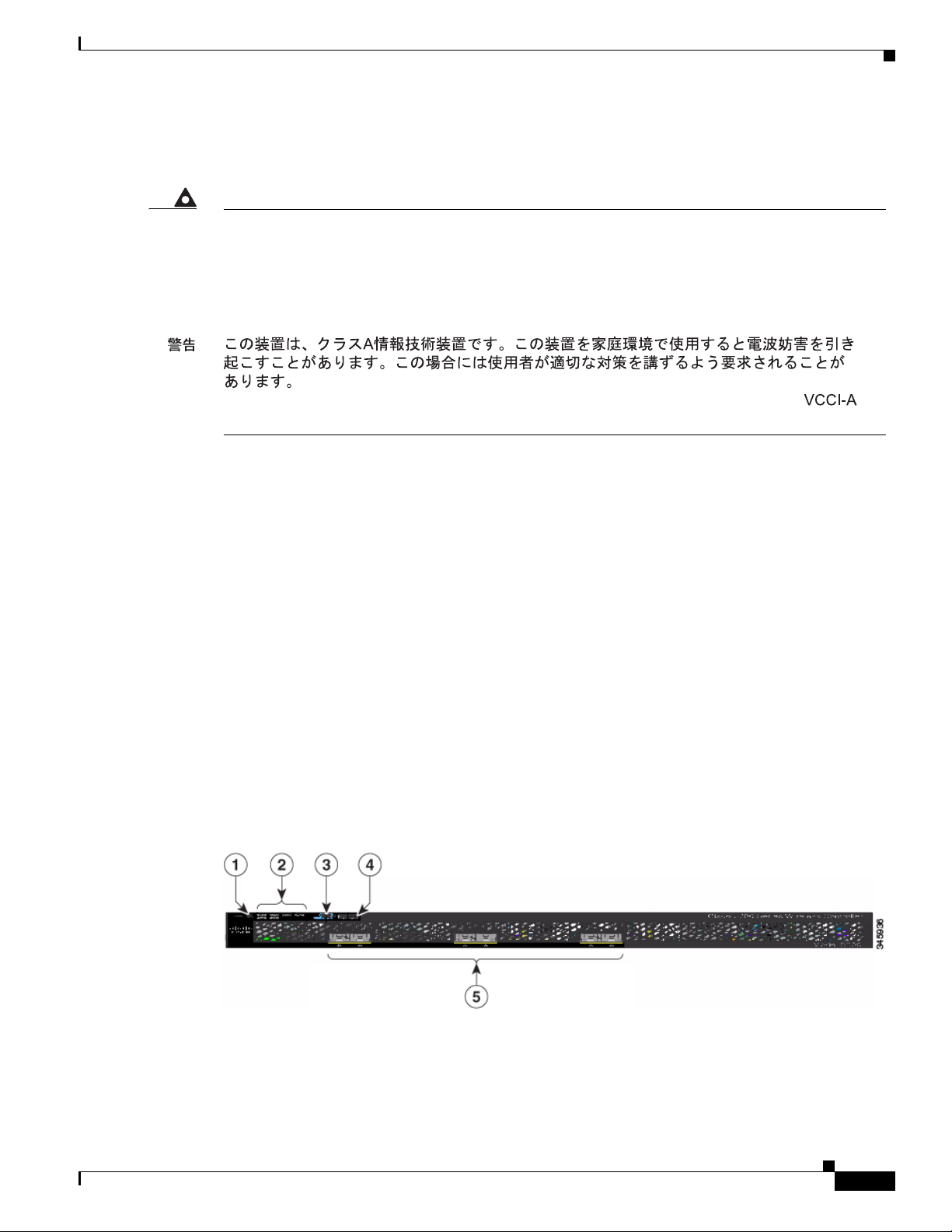
Figure 1 and Figure 2 show the front panel and back panel of the Cisco 5700 Series Wireless Controller.
Figure 1 Front Panel
Cisco 5700 Series Wireless Controller Installation Guide
3
Page 4
Controller Overview
1 Mode button 4 USB port (Type A)
2 System LEDs 5 1/10G SFP+ ports
3 USB mini-Type B (console) port
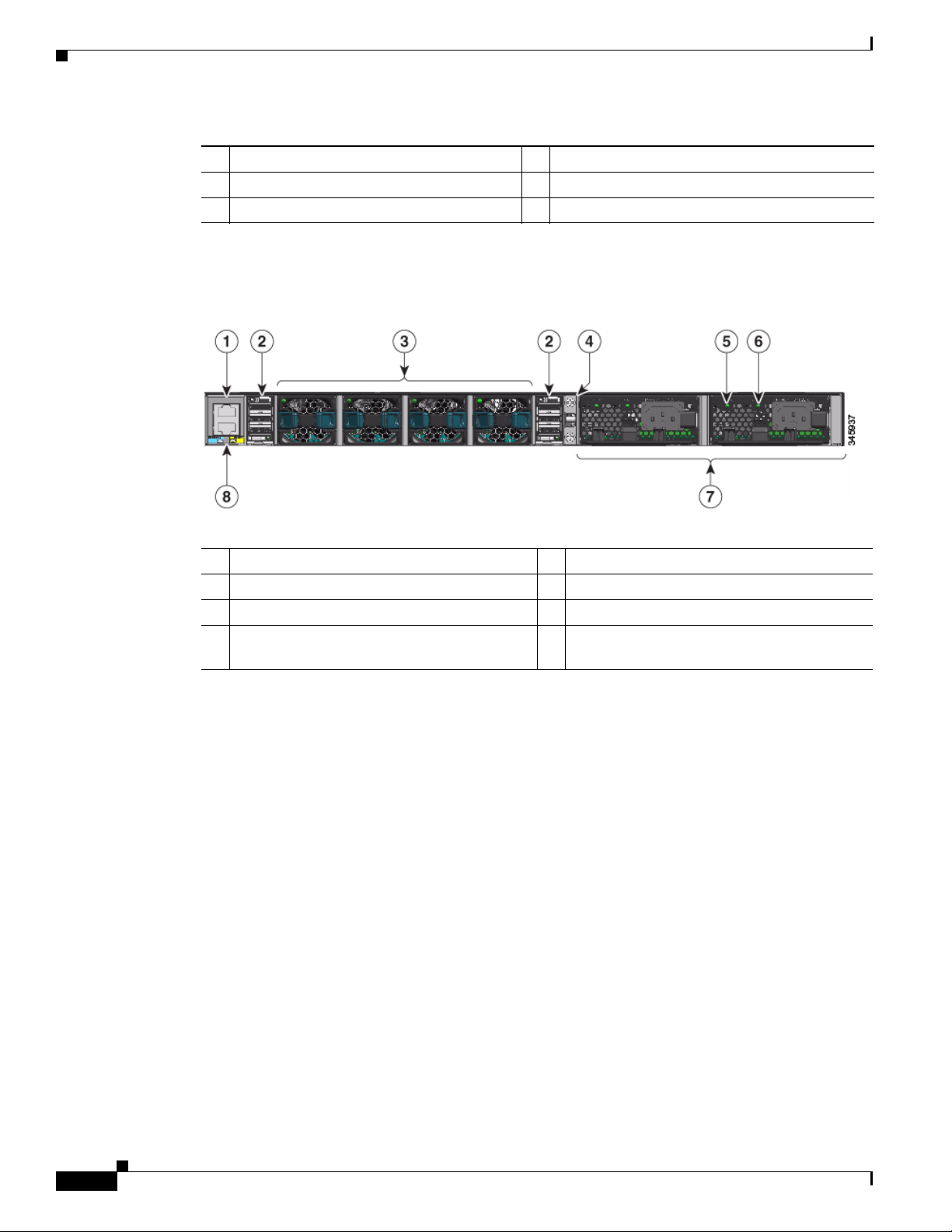
Figure 2 Back Panel
1 Console (RJ-45 console port) 5 AC OK (input) status LED
2 StackWise port 6 PS OK (output) status LED
3 Fan FRU modules 7 Redundant FRU power supplies
4 Ground lug mounting location 8 MGMT (RJ-45 10/100/1000 management
Port Connections
The controller has both EIA/TIA-232 asynchronous (RJ-45) and USB 5-pin mini Type B, 2.0 compliant
serial console ports. The default parameters for the console ports are 9600 baud, 8 data bits, 1 stop bit,
and no parity. The console ports do not support hardware flow control.
For port descriptions, see the following:
• USB Type A Port, page 4
• USB Mini-B Console Port, page 5
• 1/10G SFP+ Ports, page 6
• RJ-45 Console Port, page 9
• 10/100/1000 Ethernet Management Port, page 9
USB Type A Port
port)
The USB Type A interface provides access to external USB flash devices (also known as thumb drives
or USB keys).
The interface supports Cisco USB flash drives with capacities from 64 MB to 1 GB.
Cisco 5700 Series Wireless Controller Installation Guide
4
OL-28544-01
Page 5

Cisco IOS software provides standard file system access to the flash device: read, write, erase, and copy,
as well as the ability to format the flash device with a FAT file system.
USB Mini-B Console Port
The controller provides a USB mini-Type B console connection on the front panel, and an RJ-45 console
port on the rear panel. Console output is always active on both connectors, but console input is active on
only one connector at a time, with the USB connector taking precedence over the RJ-45 connector.
Use a USB type-A-to-USB 5-pin mini-Type B cable to connect a PC or other device to the controller.
Note The 4-pin mini-Type B connectors resemble 5-pin mini-Type B connectors. They are not compatible.
Use only the 5-pin mini-Type B.
The connected device must include a terminal emulation application.The device can be a Linux, MacOS,
or Windows device.
When the controller detects a valid USB connection to a powered device, input from the RJ-45 console
port is immediately disabled, and the input from the USB console is enabled. Removing the USB
connection immediately reenables input from the RJ-45 connection. An LED on the front panel is green
when the USB console connection is enabled.
The controller provides a configurable inactivity timeout that reactivates the RJ-45 console if no input
activity has occurred on the USB console for a specified time period. After the USB console has been
deactivated due to a timeout, you can restore its operation by disconnecting and reconnecting the USB
cable. You can disable USB console operation by using Cisco IOS commands. See the controller
software configuration guide for details.
Controller Overview
Note Only a PC that has the necessary USB console device driver causes the USB console to become active.
Plugging in a PC that does not have the USB console driver support does not cause a switchover.
When using the USB console port for operation with Microsoft Windows, you must install the Cisco
Windows USB Console Driver on any PC that is connected to the console port. If it is not installed,
prompts guide you through a simple installation process.
Note The USB console driver also works on Linux and MacOS Hosts. See the notes listed inside the Cisco
Windows USB Console driver package for installation details.
To download the latest Cisco Windows USB Console Driver, follow these steps:
Step 1 Go to the Software download page at http://www.cisco.com/cisco/software/navigator.html.
Step 2 Click Wireless.
Step 3 Click Wireless LAN Controllers.
Step 4 Click Standalone Controllers.
Step 5 Click Cisco 5700 Series Wireless LAN Controllers.
Step 6 Click USB Console Software and follow the download instructions.
OL-28544-01
Cisco 5700 Series Wireless Controller Installation Guide
5
Page 6
Controller Overview
1/10G SFP+ Ports
The SFP and SFP+ modules provide copper or fiber-optic connections to other devices. These
transceiver modules are field-replaceable, providing the physical interfaces when installed in an SFP
module slot. The SFP modules have LC connectors for fiber-optic connections or RJ-45 connectors for
copper connections.
Use only Cisco SFP and SFP+ modules on the controller.
Warning
Class 1 laser product.
Statement 1008
1/10G SFP+ port LED meanings:
• Off—The link is down.
• Green—The link is up and there is no activity.
• Blinking green—The link is up and there is activity.
• Amber—The link is disabled.
• Blinking amber—The link is off due to a fault or because a user- configurable limit has been
exceeded.
Supported Cisco SFP and SFP+ modules are listed in Table 1 and Table 2.
Table 1 Supported Cisco SFP Modules
Part Number Description
GLC-GE-100FX= 100FX SFP on GE SFP ports for LAN switches
GLC-LH-SM= GE SFP, LC connector LX/LH transceiver
GLC-LH-SMD= GE SFP, LC connector LX/LH transceiver, extended operating temperature
range
GLC-SX-MM= GE SFP, LC connector SX transceiver
GLC-SX-MMD= GE SFP, LC connector SX transceiver, extended operating temperature
range
GLC-T=
1000BASE-T SFP transceiver module for copper connections
GLC-ZX-SM= 1000BASE-ZX SFP module for SMF, 1550 nm
GLC-EX-SMD= 1000BASE-EX SFP module for SMF, 1310 nm wavelength, extended
operating temperature range
GLC-BX-D= 1000BASE-BX10 SFP module for single-strand SMF, 1490-nm TX,
1310-nm RX wavelength
GLC-BX-U= 1000BASE-BX10 SFP module for single-strand SMF, 1310-nm TX,
1490-nm RX wavelength
CWDM-SFP-1470= CWDM 1470-nm SFP Gigabit Ethernet and 1G/2G FC
CWDM-SFP-1490= CWDM 1490-nm SFP Gigabit Ethernet and 1G/2G FC
CWDM-SFP-1510= CWDM 1510-nm SFP Gigabit Ethernet and 1G/2G FC
CWDM-SFP-1530= CWDM 1530-nm SFP Gigabit Ethernet and 1G/2G FC
CWDM-SFP-1550= CWDM 1550-nm SFP Gigabit Ethernet and 1G/2G FC
CWDM-SFP-1570= CWDM 1570-nm SFP Gigabit Ethernet and 1G/2G FC
Cisco 5700 Series Wireless Controller Installation Guide
6
OL-28544-01
Page 7

Controller Overview
Table 1 Supported Cisco SFP Modules (continued)
Part Number Description
CWDM-SFP-1590= CWDM 1590-nm SFP Gigabit Ethernet and 1G/2G FC
CWDM-SFP-1610= CWDM 1610-nm SFP Gigabit Ethernet and 1G/2G FC
SFP-GE-S= 1000BASE-SX SFP module for MMF, 850 nm (DOM)
SFP-GE-L= 1000BASE-LX/LH SFP module for SMF, 1300 nm (DOM)
DWDM-SFP-3033= DWDM SFP 1530.33-nm SFP (100 GHz ITU grid)
DWDM-SFP-3112= DWDM SFP 1531.12-nm SFP (100 GHz ITU grid)
DWDM-SFP-3190= DWDM SFP 1531.90-nm SFP (100 GHz ITU grid)
DWDM-SFP-3268= DWDM SFP 1532.68-nm SFP (100 GHz ITU grid)
DWDM-SFP-3346= DWDM SFP 1533.47-nm SFP (100 GHz ITU grid)
DWDM-SFP-3425= DWDM SFP 1534.25-nm SFP (100 GHz ITU grid)
DWDM-SFP-3504= DWDM SFP 1535.04-nm SFP (100 GHz ITU grid)
DWDM-SFP-3582= DWDM SFP 1535.82-nm SFP (100 GHz ITU grid)
DWDM-SFP-3661= DWDM SFP 1536.61-nm SFP (100 GHz ITU grid)
DWDM-SFP-3739= DWDM SFP 1537.40-nm SFP (100 GHz ITU grid)
DWDM-SFP-3819= DWDM SFP 1538.19-nm SFP (100 GHz ITU grid)
DWDM-SFP-3898= DWDM SFP 1538.98-nm SFP (100 GHz ITU grid)
DWDM-SFP-3977= DWDM SFP 1539.77-nm SFP (100 GHz ITU grid)
DWDM-SFP-4056= DWDM SFP 1540.56-nm SFP (100 GHz ITU grid)
DWDM-SFP-4134= DWDM SFP 1541.35-nm SFP (100 GHz ITU grid)
DWDM-SFP-4214= DWDM SFP 1542.14-nm SFP (100 GHz ITU grid)
DWDM-SFP-4294= DWDM SFP 1542.94-nm SFP (100 GHz ITU grid)
DWDM-SFP-4373= DWDM SFP 1543.73-nm SFP (100 GHz ITU grid)
DWDM-SFP-4453= DWDM SFP 1544.53-nm SFP (100 GHz ITU grid)
DWDM-SFP-4532= DWDM SFP 1545.32-nm SFP (100 GHz ITU grid)
DWDM-SFP-4612= DWDM SFP 1546.12-nm SFP (100 GHz ITU grid)
DWDM-SFP-4692= DWDM SFP 1546.92-nm SFP (100 GHz ITU grid)
DWDM-SFP-4772= DWDM SFP 1547.72-nm SFP (100 GHz ITU grid)
DWDM-SFP-4851= DWDM SFP 1548.51-nm SFP (100 GHz ITU grid)
DWDM-SFP-4931= DWDM SFP 1549.32-nm SFP (100 GHz ITU grid)
DWDM-SFP-5012= DWDM SFP 1550.12-nm SFP (100 GHz ITU grid)
DWDM-SFP-5092= DWDM SFP 1550.92-nm SFP (100 GHz ITU grid)
DWDM-SFP-5172= DWDM SFP 1551.72-nm SFP (100 GHz ITU grid)
DWDM-SFP-5252= DWDM SFP 1552.52-nm SFP (100 GHz ITU grid)
DWDM-SFP-5332= DWDM SFP 1553.33-nm SFP (100 GHz ITU grid)
DWDM-SFP-5413= DWDM SFP 1554.13-nm SFP (100 GHz ITU grid)
DWDM-SFP-5494= DWDM SFP 1554.94-nm SFP (100 GHz ITU grid)
OL-28544-01
Cisco 5700 Series Wireless Controller Installation Guide
7
Page 8
Controller Overview
Table 1 Supported Cisco SFP Modules (continued)
Part Number Description
DWDM-SFP-5575= DWDM SFP 1555.75-nm SFP (100 GHz ITU grid)
DWDM-SFP-5655= DWDM SFP 1556.55-nm SFP (100 GHz ITU grid)
DWDM-SFP-5736= DWDM SFP 1557.36-nm SFP (100 GHz ITU grid)
DWDM-SFP-5817= DWDM SFP 1558.17-nm SFP (100 GHz ITU grid)
DWDM-SFP-5898= DWDM SFP 1558.98-nm SFP (100 GHz ITU grid)
DWDM-SFP-5979= DWDM SFP 1559.79-nm SFP (100 GHz ITU grid)
DWDM-SFP-6061= DWDM SFP 1560.61-nm SFP (100 GHz ITU grid)
DWDM-SFP-6141= DWDM SFP 1561.42-nm SFP (100 GHz ITU grid)
Table 2 Supported Cisco SFP+ Modules
Part Number Description
SFP-10G-LR= 10BASE-LR SFP+ transceiver module for SMF, 1350 nm, LC duplex
connector
SFP-10G-SR= 10BASE-SR SFP+ transceiver module for MMF, 850 nm, LC duplex
connector
SFP-10G-ER= 10GBASE-ER SFP+ transceiver module for SMF, 1550-nm, LC duplex
connector
SFP-10G-ER= 10 GBASE ER SFP+ transceiver module for SMF, 1550 nm
SFP-10G-LRM= 10BASE-LRM SFP+ module for MMF and SMF, 1310 nm
SFP-H10GB-CU1M= 10BASE-CU Twinax SFP+ cable assembly, 1 meter (Version -02)
SFP-H10GB-CU3M= 10BASE-CU Twinax SFP+ cable assembly, 3 meters (Version -02)
SFP-H10GB-CU5M= 10BASE-CU Twinax SFP+ cable assembly, 5 meters (Version -02)
Cisco 5700 Series Wireless Controller Installation Guide
8
OL-28544-01
Page 9
RJ-45 Console Port
The RJ-45 console port connection uses an RJ-45-to-DB-9 female cable.
Console port LED meanings:
• Off—The RJ-45 console is inactive (the USB console is active).
• Green—The RJ-45 console is active (the USB console is inactive).
10/100/1000 Ethernet Management Port
You can connect the controller to a host such as a Windows workstation or a terminal server through the
10/100/1000 Ethernet management port. The 10/100/1000 Ethernet management port is a VPN
routing/forwarding (VRF) interface and uses an RJ-45 crossover or straight-through cable.
Management port LED meanings:
• Off—The link is down.
• Green—The link is up and there is no activity.
• Blinking green—The link is up and there is activity.
Controller Overview
Controller’s System LEDs
If your controller is not working properly, check the LEDs on the front panel of the unit. You can use the
LED indications to quickly assess the unit’s status.
To select or change a mode, press the Mode button until the desired mode is highlighted. When you
change modes, the meanings of the LED colors also change.
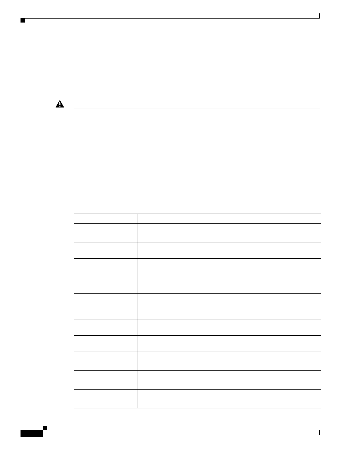
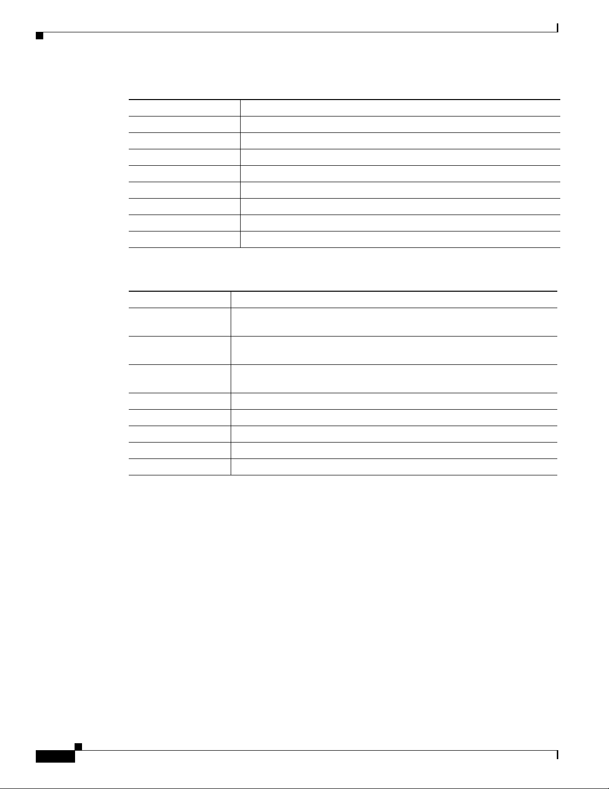
Table 3 explains how to interpret the LED colors in different modes.
Note An amber LED could indicate an error or a possible hardware failure.
Table 3 Mode LED Indicators
Mode LED Description
STAT (status) Off—The port LEDs are indicating duplex, speed, or stack status.
DUPLX (duplex) Off—The port LEDs are indicating link, speed, or stack status.
SPEED Off—The port LEDs are indicating link, duplex, or stack status.
STACK Off —The port LEDs are indicating link, duplex, or speed status.
Green—The port LEDs are indicating link status.
Green—The port LEDs are indicating duplex status.
Green—The port LEDs are indicating speed status.
Green—The port LEDs are indicating stack status.
OL-28544-01
Cisco 5700 Series Wireless Controller Installation Guide
9
Page 10

Unpacking and Installing the Controller
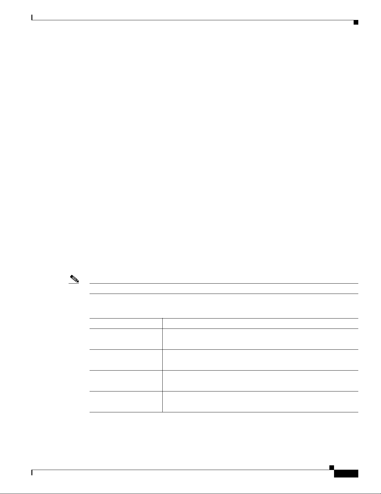
Table 3 Mode LED Indicators (continued)
Mode LED Description
SYST (system) Off—The system is off.
Green—The system is operating normally.
Blinking green—The system is running POST.
Amber—The system is malfunctioning.
Blinking amber—The power supply or fan module is malfunctioning.
ACTV (active) Off—The switch is not the active switch.
Green—The switch is the active switch or is in standalone mode.
Blinking green—The switch is in standby mode.
Amber—An error has occurred in the data stack, possibly related to active
member selection.
Unpacking and Installing the Controller
Follow these steps to unpack the Cisco 5700 Series Wireless Controller and prepare it for operation:
Step 1 Open the shipping container and carefully remove the contents.
Step 2 Return all packing materials to the shipping container and save it.
Step 3 Ensure that all items listed in the “Box Contents” section on page 11 are included in the shipment. Check
each item for damage. If any item is damaged or missing, notify your authorized Cisco sales
representative.
10
Cisco 5700 Series Wireless Controller Installation Guide
OL-28544-01
Page 11
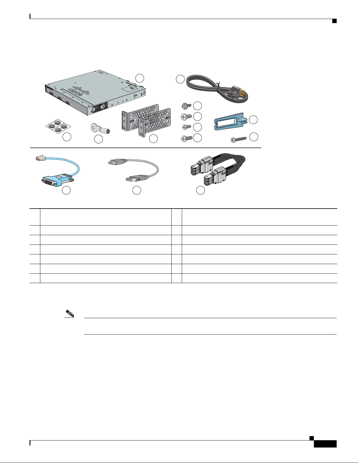
Box Contents
Unpacking and Installing the Controller
1
ACTV
Cisco 5700 Series Wireless Controller
2
6
Model 5760
7
10
8
3
12
1 Cisco 5700 Series Wireless Controller (power
supply and fan modules not shown)
4
13
1
5
9
14
8 Four number-10 pan-head screws
11
345939
2 AC power cord 9 Eight number-8 Phillips flat-head screws
3 Four rubber mounting feet 10 Cable guide
4 Ground lug ring terminal 11 M4.0 x 20mm Phillips pan-head screw
5 Two 19-inch mounting brackets 12 (Optional) RJ-45 console cable
6 One number-10 pan-head screw 13 (Optional) USB console cable
2
2
7 Four number-12 pan-head screws 14 (Optional) StackWise cable (0.5-meter, 1-meter, or 3-meter)
1. Fan modules are installed in the controller. Power supply modules are not installed in the controller.
2. Item is orderable.
2
Note Verify that you have received these items. If any item is missing or damaged, contact your Cisco
representative or reseller for instructions.
Required Tools and Information
You will need the following equipment to install the controller:
• Wireless LAN controller hardware
–
Controller with factory-supplied power cord and mounting hardware
–
Network, operating system service network, and access point cables as required
• Command-line interface (CLI) console
OL-28544-01
Cisco 5700 Series Wireless Controller Installation Guide
11
Page 12

Unpacking and Installing the Controller
–
VT-100 terminal emulator on CLI console (PC, laptop, or palmtop)
–
Null modem serial cable to connect CLI console and controller
• Local TFTP server (required for downloading operating system software updates). Cisco uses an
integral TFTP server. This means that third-party TFTP servers cannot run on the same workstation
as Cisco Prime Infrastructure because Cisco Prime Infrastructure and third-party TFTP servers use
the same communication port.
You will need the following tools before you can install the controller:
• #2 Phillips screwdriver for securing the mounting hardware
The following additional items (not found in the accessory kit) are required to ground the chassis:
• Grounding cable (6 AWG recommended), sized according to local and national installation
requirements; the required length depends on the proximity of the controller to proper grounding
facilities
• Crimping tool large enough to accommodate girth of lug
• Wire-stripping tool
Initial System Configuration Information
Obtain the following initial configuration parameters from your wireless LAN or network administrator:
• A system (controller) name.
• The enable secret password.
• The enable password.
• Virtual terminal password.
• SNMP network management configuration information.
• Management network configuration information.
• NTP server information or current time.
• A Cisco wireless LAN controller mobility group name.
• The country code for this installation. Refer to the Cisco Wireless LAN Controller Configuration
Guide for country code information. This guide is available at cisco.com.
• Wireless management interface configuration information.
Choosing a Physical Location
You can install the controller almost anywhere, but it is more secure and reliable if you install it in a
secure equipment room or wiring closet. For maximum reliability, mount the controller using the
following guidelines:
12
Warning
Cisco 5700 Series Wireless Controller Installation Guide
To prevent the system from overheating, do not operate it in an area that exceeds the maximum
recommended ambient temperature of:
104° F (40° C)
Statement 1047
OL-28544-01
Page 13

Unpacking and Installing the Controller
Warning
To prevent airflow restriction, allow clearance around the ventilation openings to be at least:
4 in (10.16 cm)
• Make sure you can reach the controller and all cables attached to it.
• Make sure that water or excessive moisture cannot get into the controller.
• Make sure that the SFP and SFP+ Module Cable Specifications are met. Each port must match the
Statement 1076
wave-length specifications on each end of the cable, and the cable must not exceed the stipulated
cable length. Copper 1000BASE-T SFP module transceivers use standard four twisted-pair,
Category 5 cable at lengths up to 328 feet (100 meters).
Table 4 describes the SFP and SFP+ Module Cable Specifications.
Table 4 Fiber-Optic SFP and SFP+ Module Port Cabling Specifications
Core
Size/Cladding
SFP Module Wavelength (nanometers) Cable Type
100BASE-FX
1310 MMF 50/125
(GLC-GE-100FX)
1000BASE-BX10-D
(GLC-BX-D)
1000BASE-BX10-U
(GLC-BX-U)
1000BASE-SX
1490 TX
SMF G.652
1310 RX
1310 TX
SMF G.652
1490 RX
850 MMF 62.5/125
(GLC-SX-MM)
(GLC-SX-MMD)
1000BASE-T
(GLC-T)
1000BASE-LX/LH
Standard 4 twisted-pair
— — — 328 feet (100 m)
Category 5 cable
1310 MMF
3
(GLC-LH-SM)
Size (micron)
62.5/125
62.5/125
50/125
50/125
62.5/125
50/125
50/125
G.652
1000BASE-ZX
SMF
1550 SMF G.652
(GLC-ZX-SM)
CWDM 1470, 1490, 1510, 1530,
SMF G.652
1550, 1570, 1590, 1610
DWDM 3033, 3112, 3190, 3268,
SMF G.652
3346, 3425, 3504, 3582,
3661, 3739, 3819, 3898,
3977, 4056, 4134, 4294,
4373, 4453, 4532, 4612,
4612, 4692, 4772, 4851,
4931, 5012, 5092, 5172,
5252, 5332, 5413, 5494,
5575, 5655, 5736, 5817,
5898, 5979, 6061, 6141
Modal
Bandwidth
(MHz/km)
500
500
2
2
— 32,810 feet (10 km)
— 32,810 feet (10 km)
160
200
400
500
2000
500
400
2
2
2
2
500
—
— 43.4 to 62 miles
— 62 miles (100 km)
— Distance is based
1
Cable Distance
6,562 feet (2 km)
6,562 feet (2 km)
722 feet (220 m)
902 feet (275 m)
1,640 feet (500 m)
1,804 feet (550 m)
32,810 feet (10 km)
1,804 feet (550 m)
1,804 feet (550 m)
1,804 feet (550 m)
32,810 feet (10 km)
(70 to 100 km)
4
on a guaranteed
power budget of 25
dB
OL-28544-01
Cisco 5700 Series Wireless Controller Installation Guide
13
Page 14

Unpacking and Installing the Controller
Table 4 Fiber-Optic SFP and SFP+ Module Port Cabling Specifications (continued)
Core
Size/Cladding
SFP Module Wavelength (nanometers) Cable Type
Size (micron)
SFP-GE-L 1300 MMF or SMF 62.5
50
50
9/10
SFP-GE-S 850 MMF 62.5
62.5
50
50
10GBASE-ER
1550 SMF G.652
(SFP-10G-ER)
10GBASE-LR
1310 SMF G.652
(SFP-10G-LR)
10GBASE-SR
(SFP-10G-SR)
850 MMF 62.5/125
62.5/125
50/125
50/125
50/125
10GBASE-LRM
(SFP-10G-LRM)
1310 MMF and
SMF
62.5
50.0
50.0
G.652
Modal
Bandwidth
(MHz/km)
500
400
500
1
Cable Distance
1804 feet (550 m)
1804 feet (550 m)
1804 feet (550 m)
6.2 miles (10 km)
160
500
400
500
2
2
160
200
400
500
2000
500
400
500
722 feet (220 m)
902 feet (275 m)
1640 feet (500 m)
1804 feet (550 m)
24.86 miles (40 km)
6.21 miles (10 km)
85 feet (26 m)
108 feet (33 m)
216 feet (66 m)
269 feet (82 m)
6,561 feet (2000 m)
722/220
328/100
722/220
984/300
14
Cisco 5700 Series Wireless Controller Installation Guide
OL-28544-01
Page 15

Table 4 Fiber-Optic SFP and SFP+ Module Port Cabling Specifications (continued)
Unpacking and Installing the Controller
SFP Module Wavelength (nanometers) Cable Type
10GBASE-CX1
(SFP-H10GB-CU1M)
(SFP-H10GB-CU3M)
— Twinax cable,
30-AWG cable
assembly
Twinax cable,
30-AWG cable
Core
Size/Cladding
Size (micron)
— — 3 feet (1 m)
Modal
Bandwidth
(MHz/km)
1
Cable Distance
9 feet (3 m)
assembly
(SFP-H10GB-CU5M)
Twinax cable,
16 feet (5 m)
24-AWG cable
assembly
1. Modal bandwidth applies only to multimode fiber.
2. A mode-field diameter/cladding diameter = 9 micrometers/125 micrometers.
3. A mode-conditioning patch cord is required. Using an ordinary patch cord with MMF or 1000BASE-LX/LH SFP modules and a short link distance can
cause transceiver saturation and an elevated bit error rate (BER). When using the LX/LH SFP module with 62.5-micron diameter MMF, you must also
install a mode-conditioning patch cord between the SFP module and the MMF cable on both the sending and receiving ends of the link. The
mode-conditioning patch cord is required for link distances greater than 984 feet (300 m).
4. 1000BASE-ZX SFP modules can send data up to 62 miles (100 km) by using dispersion-shifted SMF or low-attenuation SMF; the distance depends on
the fiber quality, the number of splices, and the connectors.
Installing the Chassis
The controller ships with rack mounting brackets and the desktop or shelf mounting rubber feet in a
separate bag.
An adjustable rack-mount kit is included for mounting the controller in a standard 19-inch (48.3 cm)
equipment rack. A standard equipment rack has two unobstructed outer posts, a minimum depth between
the front and rear mounting posts of 13 inches (33 cm), and a maximum depth of 32 inches (81.3 cm).
You can also install the controller in a 2-post equipment rack.
This kit is not suitable for racks with obstructions (such as a power strip) that could impair access to
system components.
Rack-Mounting
To install the controller in a 19-inch rack, follow the instructions described in this section.
• Rack-Mounting, page 15
• Table- or Shelf-Mounting, page 19
OL-28544-01
Cisco 5700 Series Wireless Controller Installation Guide
15
Page 16

Unpacking and Installing the Controller
Warning
To prevent bodily injury when mounting or servicing this unit in a rack, you must take special
precautions to ensure that the system remains stable. The following guidelines are provided to
ensure your safety:
• This unit should be mounted at the bottom of the rack if it is the only unit in the rack.
• When mounting this unit in a partially filled rack, load the rack from the bottom to the top with the heaviest
component at the bottom of the rack.
• If the rack is provided with stabilizing devices, install the stabilizers before mounting or servicing the unit in
the rack.
Statement 1006
The 19-inch brackets are included with the controller. Installing the controller in other rack types
requires an optional bracket kit not included with the controller. Figure 3 shows the mounting brackets
and part numbers.
Figure 3 Rack-Mounting Brackets
1
2
3 4 5
333901
16
Cisco 5700 Series Wireless Controller Installation Guide
OL-28544-01
Page 17

1 19-inch brackets (C3850-RAC-KIT=) 4 23-inch brackets (C3850-RAC-KIT=)
2 Extension rails and brackets for four-point
mounting, includes 19-inch brackets.
(C3850-4PT-KIT=)
3 ETSI brackets (C3850-RAC-KIT=)
Attaching the Rack-Mount Brackets
To install the controller in a rack, use four Phillips flat-head screws to attach the long side of the brackets
to the controller for the front- or rear-mounting positions (Figure 4). Use four screws to attach the
brackets for the front-mounting position.
Unpacking and Installing the Controller
5 24-inch brackets (C3850-RAC-KIT=)
OL-28544-01
Cisco 5700 Series Wireless Controller Installation Guide
17
Page 18

Unpacking and Installing the Controller
2
2
2
2
345727
2
2
3
2
2
1
3
es Wireless Controller
Model 5760
es Wireless Controller
Model 5760
Figure 4 Attaching Brackets for 19-inch Racks
18
1 Rear-mounting position
2 Number-8 Phillips flat-head screws
3 Front-mounting position
Cisco 5700 Series Wireless Controller Installation Guide
OL-28544-01
Page 19

Mounting the Controller in a Rack
ACT
V
Cisco 5700 Series Wireless Controller
Model 5760
4
2
1
3
345726
After the brackets are attached to the controller, use the supplied Phillips machine screws to attach the
brackets to the rack (Figure 5). Use the black Phillips machine screw to attach the cable guide to the left
or right bracket.
Figure 5 Mounting the Controller in a Rack
Unpacking and Installing the Controller
1 Phillips machine screw, black 3 Front-mounting position
2 Cable guide 4 Number-12 or number-10 Phillips machine
Table- or Shelf-Mounting
To install the controller on a table or shelf, locate the adhesive strip with the rubber feet in the
mounting-kit envelope. Attach the four rubber feet to the recessed areas on the bottom of the chassis (see
Figure 6).
Figure 6 Attaching the Adhesive Pads for Table- or Shelf-Mounting
CONSOLE
MGMT
screws
PWR-C1-715WAC
1
1
OL-28544-01
1 Adhesive pads
Cisco 5700 Series Wireless Controller Installation Guide
345728
19
Page 20

Unpacking and Installing the Controller
Insulation
Wire lead
0.5 in. (12.7 mm) ± 0.02 in. (0.5 mm)
60528
Grounding the Chassis
Follow the grounding procedures at your site and observe these warnings:
Warning
Warning
Caution We recommend grounding the chassis, even if the rack is already grounded.
Caution All power supplies must be grounded. The receptacles of the AC power cables used to provide power to
This equipment must be grounded. Never defeat the ground conductor or operate the equipment in the
absence of a suitably installed ground conductor. Contact the appropriate electrical inspection
authority or an electrician if you are uncertain that suitable grounding is available.
When installing or replacing the unit, the ground connection must always be made first and
disconnected last.
Statement 1046
Statement 1024
the chassis must be the grounding type, and the grounding conductors should connect to protective earth
ground at the service equipment.
Note The grounding lug must be NRTL listed and compatible with copper conductors. Only copper conductors
(wires) must be used and the copper conductor must comply with National Electrical Code (NEC) for
capacity.
Follow these steps to install the grounding lug on the controller. Make sure to follow any grounding
requirements at your site.
Step 1 Strip the ground wire to 0.5 inch (12.7 mm) ± 0.02 inch (0.5 mm) (see Figure 7). Stripping more than
the recommended amount of wire can leave exposed wire from the connector.
Figure 7 Stripping the Ground Wire
Step 2
Step 3 Using a Panduit crimping tool, crimp the ground lug to the wire.
Step 4 Remove the grounding bracket from the back of the controller by unscrewing the two phillips flat-head
Slide the open end of the ground lug over the exposed area of the wire.
screws holding on the bracket (see Figure 8).
Cisco 5700 Series Wireless Controller Installation Guide
20
OL-28544-01
Page 21

Step 5 Install the ground lug:
a. Remove the first hex nut from the bracket and place the ground lug over the screw threads.
b. Place the hex nut back on the screw threads and tighten.
Step 6 Reinstall the ground bracket onto the controller.
Figure 8 Ground Bracket
Unpacking and Installing the Controller
Step 7
Prepare the other end of the grounding cable and connect it to an appropriate grounding point in your
site to ensure adequate earth ground.
Preventing ESD Damage
Electrostatic discharge (ESD) damage occurs when electronic cards or components are improperly
handled and can result in complete or intermittent failures.
Always use an ESD-preventive wrist or ankle strap and ensure that it makes good skin contact. Connect
the strap to any unpainted surface on the chassis.
Caution Periodically check the resistance value of the antistatic strap. The measurement should be between 1 and
10 megohms (Mohms).
Connecting the Controller’s Console Port
Before you can configure the controller for basic operations, you need to connect it to a PC that uses a
VT-100 terminal emulator (such as HyperTerminal, ProComm, Minicom, or Tip).
OL-28544-01
Cisco 5700 Series Wireless Controller Installation Guide
21
Page 22

Using the Startup Wizard
Note You can use either the RJ-45 console port or the USB console port.
Note The first time that you connect a Windows PC to the USB console port, you are prompted to install the
Step 1 If you use the CONSOLE port, plug the RJ-45 connector on a null-modem serial cable into the
Step 2 Start the PC’s terminal emulation program.
Step 3 Configure the terminal emulation program for the following parameters:
USB console driver. Follow the installation prompts to install the driver. The USB console driver maps
to a COM port on your PC; you then need to map the terminal emulator application to the COM port.
See the “USB Mini-B Console Port” section on page 5 for more information about the USB console
driver.
Follow these steps to connect the PC to the controller’s console port:
controller’s CONSOLE port and the other end of the cable into the PC’s serial port.
If you use the USB console port, plug the 5-pin mini Type B connector into the controller’s USB console
port and the other end of the cable into the PC’s USB Type A port.
• 9600 baud
• 8 data bits
• No flow control
• 1 stop bit
• No parity
Using the Startup Wizard
Before you can use the startup wizard, you may need to obtain the information discussed in the
“Required Tools and Information” section on page 11. Also, you will need to know the following
information:
• Management network interface IP Address
• Wireless management interface IP Address
• VLAN number for the wireless management interface
At any point you may enter a question mark (?) for help. Press Ctrl-C to abort the configuration dialog
at any prompt. Default settings are enclosed with square brackets ([]).
Basic management setup configures only enough connectivity for management of the system, extended
setup will ask you to configure each interface on the system.
To configure the controller for basic operation using the Startup Wizard, follow these steps:
22
Step 1 When prompted to enter basic management setup, enter yes.
Step 2 Enter the hostname, which is the name you want to assign to the controller.
Cisco 5700 Series Wireless Controller Installation Guide
OL-28544-01
Page 23

Using the Startup Wizard
Step 3 Enter the enable secret password. This password is used to protect access to privileged EXEC and
configuration modes. This password, after entered, becomes encrypted.
Step 4 Enter the enable password. This password is used when you do not specify an enable secret password
(for some older software versions, and some boot images).
Step 5 Enter the virtual terminal password. This password is used to protect access to the controller over a
network interface.
Step 6 If you want the controller to receive its time setting from an external Network Time Protocol (NTP)
server when it powers up, enter yes to configure an NTP server. Otherwise, enter no.
• If you enter yes:
a. Enter the NTP server address.
b. Enter the polling interval (between 16 and 131072 secs, which is a power of 2).
• If you enter no:
a. Enter yes to configure the system time.
b. Enter the current date in MM/DD/YY format and the current time in HH:MM:SS format.
Step 7 To configure the wireless network, enter yes.
Step 8 If desired, enter the name of the mobility group to which you want the controller to belong.
Step 9 Enter the code for the country in which the controller will be used.
Step 10 When prompted to configure the SNMP network management, enter yes or no.
• If you enter yes, enter the Community String.
• If you enter no, proceed to the next step.
Step 11 Perform management network configuration. The current interface summary appears.
For an example:
Interface IP-Address OK? Method Status Protocol
Vlan1 unassigned YES NVRAM administratively down down
GigabitEthernet0/0 unassigned YES unset administratively down down
Te1/0/1 unassigned YES unset up up
Te1/0/2 unassigned YES unset down down
Te1/0/3 unassigned YES unset down down
Te1/0/4 unassigned YES unset down down
Te1/0/5 unassigned YES unset down down
Te1/0/6 unassigned YES unset down down
a. Enter the interface name used to connect to the management network from the above summary. In
this example, the interface name is GigabitEthernet0/0.
b. To configure the IP address on the interface, enter yes.
c. Enter the IP address for the interface.
d. Enter the subnet mask for the interface.
Step 12 Configure the wireless management interface.
The wireless management interface must be configured at startup. It should be mapped to an SVI that is
not Vlan1.
a. Enter the VLAN number for the wireless management interface.
b. Enter the IP address for the interface.
c. Enter the IP address mask for the interface.
OL-28544-01
Cisco 5700 Series Wireless Controller Installation Guide
23
Page 24

Using the Startup Wizard
Step 13 When prompted to verify that the configuration is correct, enter one of the following:
• 0—Go to the IOS command prompt without saving this config.
• 1—Return back to the setup without saving this config.
• 2—Save this configuration to nvram and exit.
Logging into the Controller
Follow these steps to log into the controller:
Step 1 Enter a valid username and password to log into the controller CLI.
Note The administrative username and password you created in the Startup Wizard are case
sensitive.
Step 2 The CLI displays the root level system prompt:
#(system prompt)>
The system prompt can be any alphanumeric string up to 31 characters. You can change it by entering
the config prompt command.
Note The CLI automatically logs you out without saving any changes after 5 minutes of inactivity.
You can set the automatic logout from 0 (never log out) to 160 minutes using the config
serial timeout command.
Note Cisco Aironet lightweight access points do not connect to the Cisco 5700 Series Wireless
Controller if the date and time are not set properly. Set the current date and time on the
controller before allowing the access points to connect to it.
Verifying Interface Settings and Port Operation
Follow these steps to verify that your interface configurations have been set properly and the controller’s
ports are operational.
Step 1 Enter show interface summary. The controller’s current interface configurations appear:
24
Interface Name Port Vlan Id IP Address Type Ap Mgr Guest
-------------------------------- ---- -------- -------------- ------- ------- ----management LAG untagged 10.91.104.93 Static Yes No
service-port N/A N/A 10.10.0.9 Static No No
virtual N/A N/A 1.1.1.1 Static No No
Cisco 5700 Series Wireless Controller Installation Guide
OL-28544-01
Page 25

Step 2 Enter show port summary. The following information appears, showing the status of the controller’s
distribution system ports, which serve as the data path between the controller and Cisco lightweight
access points and to which the controller’s management interface is mapped.
STP Admin Physical Physical Link Link Mcast
Pr Type Stat Mode Mode Status Status Trap Appliance POE
-- ------- ---- ------- ---------- ---------- ------ ------- --------- ------1 Normal Forw Enable Auto 1000 Full Up Enable Enable N/A
2 Normal Forw Enable Auto 1000 Full Up Enable Enable N/A
A link status of Up indicates that the controller’s ports are fully operational.
Connecting the Console Port (Optional)
The console port is controlled by the console-port interface and is reserved for out-of-band management
of the controller and system recovery and maintenance in the event of a network failure. The
console-port interface enables the controller to be managed on an interface different from the one used
for your network traffic. Use of the console port is optional.
You can perform out-of-band controller management from a PC running a terminal emulation program
or a PC running Cisco Prime infrastructure, a network management tool that enables you to configure
and monitor a network of controllers, or the controller GUI. However, you must first connect the PC to
the switch’s console port in one of two ways:
• Use an Ethernet cross-over cable to connect the PC directly to the switch’s console port.
Power Supply Installation
• For a remote connection (using Telnet or SSH) through a dedicated management network, use a
Category 5, Category 5e, Category 6, or Category 7 Ethernet cable to connect the management
network to the controller’s console port and the appropriate cable to connect the PC to the
management network.
Connecting Access Points
After you have configured the controller, use Category-5, Category-5e, Category-6, or Category-7
Ethernet cables to connect Cisco lightweight access points to the network.
As soon as the controller is operational, it starts to scan for access points. When it detects an access point,
it records the access-point MAC address in its database. The controller Radio Resource Management
(RRM) feature then automatically configures the access point to start sending and allowing clients to
associate.
You have prepared the controller for basic operation. Refer to the Cisco Wireless LAN Controller
Configuration Guide, Release 6.0, for information on configuring the controller to meet the specific
needs of your wireless network.
Power Supply Installation
The controller can be powered using one or two power supply units. When the controller is equipped
with two power supply units, the power supplies are redundant. Either power supply continues to power
the controller should the other power supply unit fail. Also, the power supplies are hot swappable; you
do not need to remove power from the controller to replace a power supply.
OL-28544-01
Cisco 5700 Series Wireless Controller Installation Guide
25
Page 26

Power Supply Installation
One power supply unit is installed in slot 1 at the factory. You can order a second power supply unit and
install it in slot 2.
The power supplies do not have an on/off switch and can only be powered down by removing AC input.
Note If only one power supply will be used, you must use the supplied blank faceplate to cover the empty
power slot.
Power Supply Module Overview
All power supply modules have internal fans. All controllers ship with a blank cover in the second power
supply slot.
Table 5 describes the supported internal power supply module.
Table 5 Power Supply Module Part Numbers and Descriptions
Part Number Description
PWR-C1-350WAC= 350-W AC power supply module
PWR-C1-BLANK Blank cover
The 350-W AC power supply module is an autoranging unit that supports input voltages between 100
and 240 VAC.
The power supply module uses an 18- AWG power cord for connection to an AC power outlet.
Figure 9 350-W AC Power Supply Module
1
2
3
4
AC OK
PS OK
PWR-C1-350WAC
6
5
7
334377
1 350-W AC power supply module 5 Release latch
2 AC OK LED 6 Power cord retainer
3 PS OK LED 7 Keying feature
4 AC power cord connector
26
If no power supply is installed in a power supply slot, install a power supply slot cover (Figure 10).
Cisco 5700 Series Wireless Controller Installation Guide
OL-28544-01
Page 27

Figure 10 Power Supply Slot Cover
Power Supply Installation
2
1 Release handles 2 Retainer clips
Table 6 describes the power supply modules status LEDs.
Table 6 Power Supply Module LEDs
AC Power Supply Module LEDs
AC OK Description PS OK Description
Off
(AC LED is
off)
Green AC input power present. Green Power output to the controller.
Installation Guidelines
Observe these guidelines when removing or installing a power supply or fan module:
• Do not force the power supply or fan module into the slot. This can damage the pins on the controller
if they are not aligned with the module.
• A power supply that is only partially connected to the controller can disrupt the system operation.
1
253564
No AC input power. Off Output is disabled, or input is
outside operating range.
Red Output has failed.
OL-28544-01
• Remove power from the power-supply module before removing or installing the module.
Caution Do not operate the controller with one power-supply module slot empty. For proper chassis cooling, both
module slots must be populated, with either a power supply or a blank module.
Warning
Blank faceplates and cover panels serve three important functions: they prevent exposure to
hazardous voltages and currents inside the chassis; they contain electromagnetic interference (EMI)
that might disrupt other equipment; and they direct the flow of cooling air through the chassis. Do not
operate the system unless all cards, faceplates, front covers, and rear covers are in place.
Statement 1029
Cisco 5700 Series Wireless Controller Installation Guide
27
Page 28

Power Supply Installation
Warning
Warning
Warning
Installation of the equipment must comply with local and national electrical codes.
Do not reach into a vacant slot when installing or removing a module. Exposed circuitry is an energy
hazard.
Statement 206
Only trained and qualified personnel should be allowed to install, replace, or service this equipment.
Statement 1030
Installing or Replacing an AC Power Supply
Step 1 Turn off the power at its source.
Step 2 Remove the power cord from the power cord retainer.
Step 3 Remove the power cord from the power connector.
Step 4 Press the release latch at the right side of the power supply module inward and slide the power supply
out. (Figure 11).
Caution Do not leave the power-supply slot open for more than 90 seconds while the controller is operating.
Statement 1074
Warning
This unit might have more than one power supply connection. All connections must be removed to
de-energize the unit.
Statement 1028
Step 5 Insert the new power supply into the power-supply slot, and gently push it into the slot (Figure 11). When
correctly inserted, the 350-W power supply (excluding the power cord retainer) are flush with the
controller rear panel.
Figure 11 Inserting the AC-Power Supply in the Controller
PWR-C1-715WAC
CONSOLE
MGMT
Step 6
(Optional) Make a loop in the power cord and thread it through the power cord retainer (Figure 12).
345731
28
Cisco 5700 Series Wireless Controller Installation Guide
OL-28544-01
Page 29

334334, 781-00765-01
SN: XXXNNNNXXXX
PWR-C1-715WAC
Figure 12 AC-Power Supply with Power Cord Retainer
AC OK
AC OK
PS OK
PWR-C1-715WAC
PWR-C1-715WAC
PS OK
Step 7 Connect the power cord to the power supply and to an AC power outlet. Turn on the power at the power
source.
Step 8 Confirm that the power supply AC OK and PS OK LEDs are green.
Finding the Power Supply Module Serial Number
If you contact Cisco Technical Assistance regarding a power supply module, you need to know the serial
number. See Figure 13 to find the serial number. You can also use the CLI to find out the serial number.
Power Supply Installation
345730
Figure 13 350-W AC Power Supply Module Serial Number
OL-28544-01
Cisco 5700 Series Wireless Controller Installation Guide
29
Page 30

Installing a Fan Module
Installing a Fan Module
This section describes how to install a fan module.
• Fan Module Installation, page 30
• Finding the Fan Module Serial Number, page 31
The controller has four fan modules. Fan modules are hot-swappable. The controller can operate with
one fan failure indefinitely, but the faulty fan should be replaced as soon as possible to avoid service
disruption due to a second fan failure.
Figure 14 Fan Module
1
4
1 Fan LED 3 Retainer clip
2 Exhaust vent 4 Extraction handles
Fan Module Installation
2
3
344200
30
Installation Guidelines
Observe these guidelines when removing or installing a fan module:
• Do not force the fan module into the slot. This can damage the pins on the controller if they are not
aligned with the module.
• A fan module that is only partially connected can disrupt the system operation.
• The controller supports hot swapping of the fan module. You can remove and replace the module
without interrupting normal controller operation.
Warning
Step 1 Pinch the fan module release handle, and slide the module out.
Cisco 5700 Series Wireless Controller Installation Guide
Only trained and qualified personnel should be allowed to install, replace, or service this equipment.
Statement 1030
OL-28544-01
Page 31

Installing a Fan Module
Caution You should replace the fan module within 5 minutes to avoid overheating the controller.
Step 2 Install the fan module in the fan slot, and firmly push it into the slot, applying pressure to the end of the
module, not the extraction handles. When correctly inserted, the fan module is flush with the controller
rear panel. When the fan is operating, a green LED is on in the top left corner of the fan. See Figure 15.
Warning
Do not reach into a vacant slot when installing or removing a module. Exposed circuitry is an energy
hazard.
Statement 206
Figure 15 Installing the Fan Module
PWR-C1-715WAC
CONSOLE
MGMT
1
1 Fan LED
345732
Finding the Fan Module Serial Number
If you contact Cisco Technical Assistance regarding a fan module, you need to know the fan module
serial number. See Figure 16 for the serial number location.
OL-28544-01
Cisco 5700 Series Wireless Controller Installation Guide
31
Page 32

Specifications
SN: XXXNNNNXXXX
334328,781-00761-01
Figure 16 Fan Module Serial Number
Specifications
Table 7 through Ta ble 9 list the specifications for the controller and its power supply and fan modules.
Table 7 Environmental and Physical Specifications for the Cisco 5700 Series Wireless
Controller
Environmental Ranges
Operating
1
temperature
23 to 113° F (–5 to 45° C)
Storage temperature –40 to 158° F (–40 to 70° C)
Relative humidity 5 to 95% (non-condensing)
Operating altitude Up to 10,000 ft (3,000 m)
Storage altitude Up to 15,000 ft (4,600 m)
Physical Specifications
Dimensions (H x W x D) 1.75 x 17.5 x 17.7 in. (4.45 x 44.5 x 45.0 cm)
Weight 19.6 lbs (8.9 kg) with two power supplies installed
17.1 lbs (7.8 kg) with a single power supply installed
1. Minimum ambient temperature for cold start is 32° F (0° C)
Table 8 Environmental and Physical specifications for the Power Supply Module
Environmental Ranges
Operating temperature 23 to 113° F (–5 to 45° C)
Storage temperature –40 to 158° F (–40 to 70° C)
Relative humidity 10 to 95% (non-condensing)
Altitude Up to 10,000 ft (3,000 m)
32
Cisco 5700 Series Wireless Controller Installation Guide
OL-28544-01
Page 33

Cisco 90-Day Limited Hardware Warranty Terms
Table 8 Environmental and Physical specifications for the Power Supply Module (continued)
Physical Specifications
Weight
PWR-C1-350WAC 2.6 lb (1.2 kg)
Dimensions (H x D x W)
PWR-C1-350WAC 1.58 x 10.22 x 3.25 in. (4 x 26 x 8.3 cm)
Note Dimensions shown exclude the extraction handle,
which measures 1.55 in (3.9 cm) and the keying
feature which measures 0.44 in (1.1 cm).
Table 9 Environmental and Physical Specifications for the Fan Module
Environmental Ranges
Operating temperature 23 to 176° F (–5 to 80° C)
Storage temperature –40 to 185° F (–40 to 85° C)
Relative humidity 5 to 95% (non-condensing)
Altitude Up to 13,000 ft (4,000 m)
Physical Specification
Dimensions (H x D x W) 1.62 x 1.73 x 4.24 in. (4.11 x 4.39 x 10.76 cm)
Weight 0.2 lb (0.07 kg)
Operating Specification
Airflow 20 cfm
Cisco 90-Day Limited Hardware Warranty Terms
There are special terms applicable to your hardware warranty and various services that you can use
during the warranty period. Your formal Warranty Statement, including the warranties and license
agreements applicable to Cisco software, is available on Cisco.com. Follow these steps to access and
download the Cisco Information Packet and your warranty and license agreements from Cisco.com.
1. Launch your browser, and go to this URL:
http://www.cisco.com/en/US/products/prod_warranties_listing.html
The Warranties and License Agreements page appears.
2. To read the Cisco Information Packet, follow these steps:
a. Click the Information Packet Number field, and make sure that the part number
78-5235-03B0 is highlighted.
b. Select the language in which you would like to read the document.
c. Click Go.
The Cisco Limited Warranty and Software License page from the Information Packet appears.
d. Read the document online, or click the PDF icon to download and print the document in Adobe
Portable Document Format (PDF).
Cisco 5700 Series Wireless Controller Installation Guide
OL-28544-01
33
Page 34

Obtaining Documentation and Submitting a Service Request
Note You must have Adobe Acrobat Reader to view and print PDF files. You can download the
reader from Adobe’s website: http://www.adobe.com
3. To read translated and localized warranty information about your product, follow these steps:
a. Enter this part number in the Warranty Document Number field:
78-5236-01C0
b. Select the language in which you would like to read the document.
c. Click Go.
The Cisco warranty page appears.
d. Review the document online, or click the PDF icon to download and print the document in
Adobe Portable Document Format (PDF).
Click this link to browse to the Cisco Support and Documentation page:
http://www.cisco.com/cisco/web/support/index.html
Duration of Hardware Warranty
Ninety (90) days.
Replacement, Repair, or Refund Policy for Hardware
Cisco or its service center will use commercially reasonable efforts to ship a replacement part within ten
(10) working days after receipt of a Return Materials Authorization (RMA) request. Actual delivery
times can vary, depending on the customer location.
Cisco reserves the right to refund the purchase price as its exclusive warranty remedy.
To Receive a Return Materials Authorization (RMA) Number
Contact the company from whom you purchased the product. If you purchased the product directly from
Cisco, contact your Cisco Sales and Service Representative.
Complete the information below, and keep it for reference:
Company product purchased from
Company telephone number
Product model number
Product serial number
Maintenance contract number
Obtaining Documentation and Submitting a Service Request
34
For information on obtaining documentation, submitting a service request, and gathering additional
information, see the monthly What’s New in Cisco Product Documentation, which also lists all new and
revised Cisco technical documentation, at:
http://www.cisco.com/en/US/docs/general/whatsnew/whatsnew.html
Cisco 5700 Series Wireless Controller Installation Guide
OL-28544-01
Page 35

Subscribe to the What’s New in Cisco Product Documentation as a Really Simple Syndication (RSS) feed
and set content to be delivered directly to your desktop using a reader application. The RSS feeds are a free
service and Cisco currently supports RSS Version 2.0.
Related Documentation
Before installing or upgrading the controller, refer to the controller release notes.
• Cisco 5700 Series Wireless Controller documentation at:
http://www.cisco.com/en/US/products/ps12598/tsd_products_support_series_home.html
• Cisco SFP and SFP+ modules documentation, including compatibility matrixes at:
http://www.cisco.com/en/US/products/hw/modules/ps5455/tsd_products_support_series_home.ht
ml
• Cisco Validated Designs documents at:
http://www.cisco.com/go/designzone
Related Documentation
OL-28544-01
Cisco and the Cisco logo are trademarks or registered trademarks of Cisco and/or its affiliates in the U.S. and other countries. To view a list of
Cisco trademarks, go to this URL: www.cisco.com/go/trademarks. Third-party trademarks mentioned are the property of their respective owners. The
use of the word partner does not imply a partnership relationship between Cisco and any other company. (1110R)
Any Internet Protocol (IP) addresses and phone numbers used in this document are not intended to be actual addresses and phone numbers. Any
examples, command display output, network topology diagrams, and other figures included in the document are shown for illustrative purposes only.
Any use of actual IP addresses or phone numbers in illustrative content is unintentional and coincidental.
© 2013 Cisco Systems, Inc. All rights reserved.
Cisco 5700 Series Wireless Controller Installation Guide
35
Page 36

Related Documentation
36
Cisco 5700 Series Wireless Controller Installation Guide
OL-28544-01
 Loading...