

Cisco AIR-BR1410A-A-K9, AIR-BR1410A-E-K9, AIR-BR1410A-A-K9-N, AIR-BR1410A-K-K9, AIR-BR1410A-Z-K9 Deployment Manual
Page 1
1400 Series Wireless Bridge Outdoor Deployment Guide
The purpose for this document is to cover 5 GHz Regulations, 1400 Series Wireless Bridge
Product, interference issues, installation guide, troubleshooting tips and added features. This guide
will help a Network IT professional, who has limited knowledge about RF, but desires to deploy
a wireless Bridge link. This document covers topics that one needs to understand to determine if
the wireless link will work, how to design it, how to install it, optimize the link, maintain and
troubleshoot it.
1 Introduction to Technology
The BR1400 Bridges are used to wirelessly connect two networks (usually in different buildings).
When two or more bridges are used, one bridge must be defined as the ROOT BRIDGE. Cisco
wireless bridges default to operation in root bridge mode. In any bridge domain (group of
connected bridges) there should exist only one Root Bridge. Other bridges must be configured to
operate in non-root mode. The NON-ROOT Bridge will initiate a link to the root bridge and all
bridges can subsequently transmit data.
Longer ranges can be activated with appropriate selection of antennas and clear line of sight. It
should be noted that only bridges have this extended range capability. The extended range is
achieved by stretching the timing parameters set forth in the IEEE 802.11 specifications. The
802.11 specification was based on a presumption that a wireless LAN communication link
(keeping in mind this is defining a LOCAL Area Network) would be not more than 1000 feet.
Therefore distances for Access Point to client communication are limited to approximately one-mile
range for quality performance; irrespective of transmit power, cable, and antenna combinations.
This is due to timing restrictions in the 802.11 protocol which synchronize the timing of the
communications to support delays induced by the distance.
Copyright © 2004 Cisco Systems, Inc. All rights reserved.
Page 1 of 53
Page 2
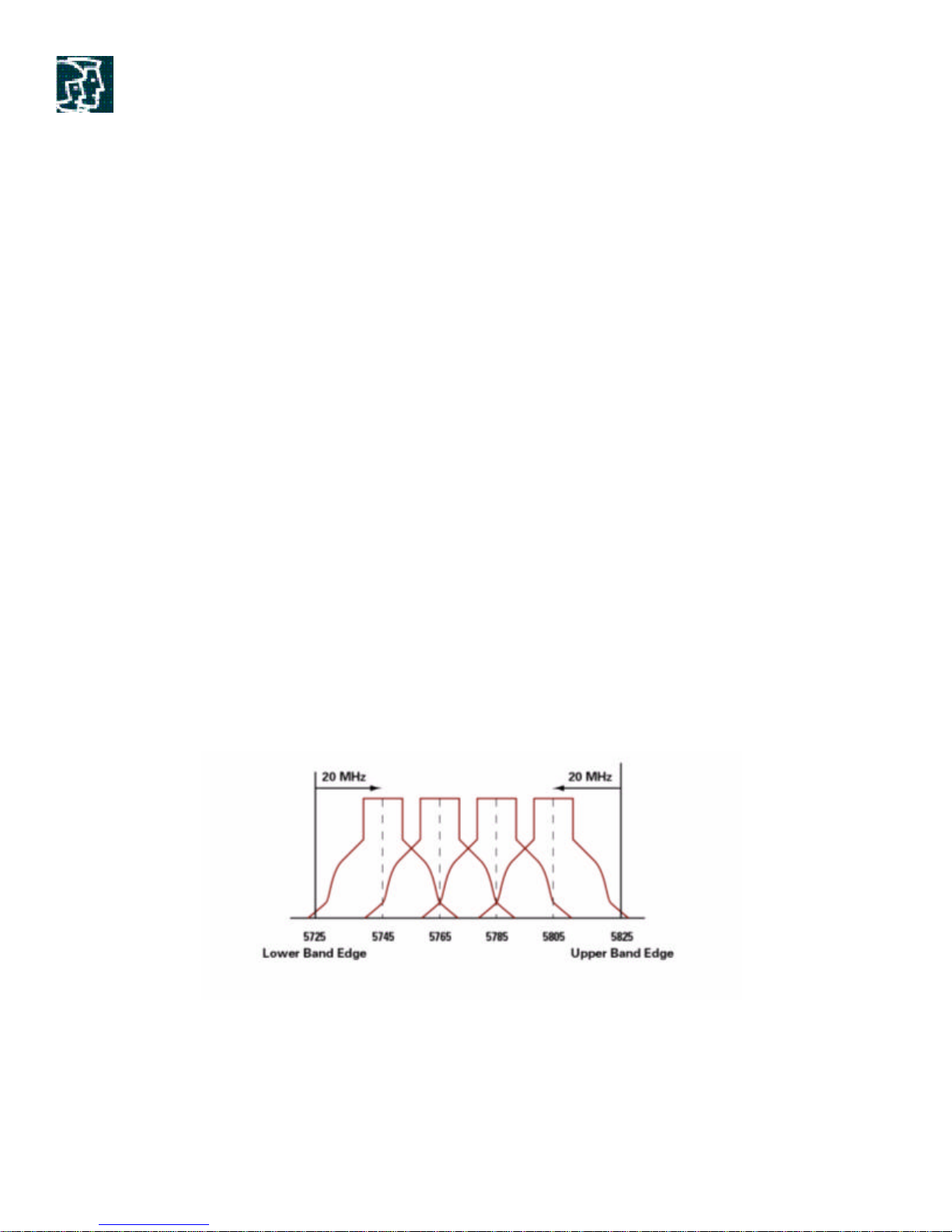
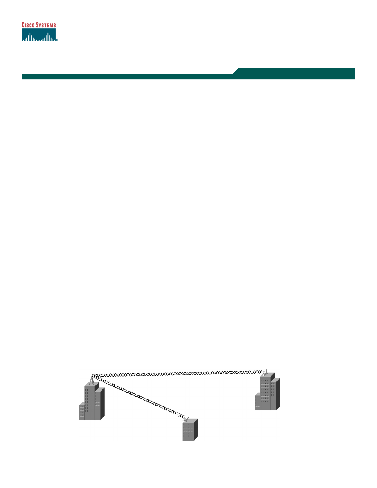
Figure 1. Typical Bridge application used to connect different buildings across a
campus or a metro area
Cisco Aironet Bridges support IEEE 802.1d Spanning Tree and can therefore participate in
complex Layer 2 network designs involving redundant or meshed links.
1.1 Channels and Data Rates
IEEE 802.11a defines requirements for a PHY operating in the 5.0 GHz Unlicensed National
Information Infrastructure (UNII) frequency band and data rates ranging from 6 Mbps to 54 Mbps
in seven increments-6, 9, 12, 18, 24, 36, 48 & 54 Mbps. It uses the Orthogonal Frequency
Division Multiplexing-, which is a multi carrier system as compared to single carrier systems.
OFDM allows sub channels to overlap, giving us a high spectral efficiency. The modulation
technique allowed in (OFDM) is more efficient than the spread spectrum techniques use. More bits
are stuffed per second per hertz and provides up to 54 Mbps of data rate to network users.
For US-based 802.11a standard, the 5GHz unlicensed band covers 300 MHz of spectrum and
supports 12 non-overlapping channels. The channel frequencies and numbering defined in IEEE
802.11a start at 5 GHz for United States and each channel is spaced 5 MHz apart. The Figure 2
below shows the center frequency of the channels. The frequency of the channel is 10MHz either
side of the dotted line.
Figure 2. UNII 3 Band
Copyright © 2004 Cisco Systems, Inc. All rights reserved.
Page 2 of 53
Page 3

The 5GHz Band is actually a conglomerate of three Bands in USA: 5.150-5.250(UNII 1), 5.250-
5.350(UNII 2), and 5.725-5.875(UNII 3) GHz. UNII-1 and the UNII-2 bands are contiguous
and are indeed treated by 802.11a as being a continuous swath of spectrum 200MHz wide, more
than twice the size of the 2.4GHz ISM band. This results in a key benefit for 802.11a—the
200MHz wide UNII-1 and UNII-2 bands are divided up into eight non-overlapping channels,
each 25MHz wide.
1.2 Regulations
Outdoor Bridging utilizes UNII 3 band and there are regulatory limitations that apply in this band.
1.2.1 Federal Communications Commission (FCC) Regulations with respect to the
UNII 3 Band
Devices that operate in Unlicensed Bands do not require any formal licensing process, but
operations in these bands still obligate the user to follow regulations. The geographical bodies in
different parts of the world regulate these Bands. WLAN devices must comply with the local
geographical regulatory domains. The regulatory agencies set the radio emission requirements for
WLAN to minimize the amount of interference a radio can generate or receive from another in the
same proximity. The Federal Communications Commission (FCC) is responsible for framing rules
and regulations for WLAN operations in a particular band in United States. The set of FCC
regulations that apply to WLAN operation in the 5 GHz band is a subset of FCC Part 15
regulations. In addition to US, Australia, New Zealand and various parts of Asia and Oceania also
fall in the FCC regulatory domain.
For latest information please refer to the following URL:
www.cisco.com/go/aironet/compliance
http://www.cisco.com/warp/public/779/smbiz/wireless/approvals.html
1.2.2 Effective Isotropic Radiated Power (EIRP)
The radio energy radiated from an antenna is called the Effective Isotropic Radiated Power (EIRP).
The EIRP is usually expressed in Watts or dBm. To enable fair and equitable sharing of the
unlicensed band, regulatory domains impose maximum EIRP levels.
Directional antennas, such as Yagi and Parabolic dishes have the capability of shaping the signal
from the transmitter so it appears stronger in a particular direction (much the same as the reflector
on a flashlight strengthens a light beam). This is known as antenna gain.
Antenna cables can add loss attenuating the transmitted signal. The longer the cable, the more
attenuation, and the more signal loss in the cable affecting both receive and transmit. Cable
attenuation is dependent upon the grade and manufacturer. Low-loss cable is typically around 6.7
dB per 100 ft (30m) at 2.4GHz.
As the EIRP is a measure of the power out of the antenna, the EIRP must include the antenna gain
and the cable loss together with the power out of the transmitter.
Copyright © 2004 Cisco Systems, Inc. All rights reserved.
Page 3 of 53
Page 4
1W
4W
1.2.3 Power Levels
The UNII-2 band is intended for wireless bridging both for indoor applications as well as short
range outdoor applications. UNII-3 band, with far greater transmit power and antenna gain
allowances is preferable for long range outdoor wireless bridging.
To facilitate this, the regulations allow for connectors and the use of cable and auxiliary antennas for
both of these bands. The effective radiated power allowed in UNII-3 band is 4 watts (36 dBm),
which is much more than the radiated power of 1 watt (30 dBm) allowed in UNII-2 band. Rather,
the UNII-2 band is treated by the Wi-Fi community as being a less-restrictive extension of the
UNII-1 band generally supporting clients and Access Points.
The channel numbers corresponding to the four centre frequencies for UNII-3 band are 149,153,
157 and 161.
Regulatory Domain Frequency Band Channel number Centre frequencies
USA UNII middle band
5.725-5.825 GHz
149
153
157
161
5.745 GHz
5.765 GHz
5.785 GHz
5.805 GHz
Table 1. Channel Numbers for UNII-3 Band
The maximum antenna gain allowed is 6dBi. The transmit power may be reduced to accommodate
higher gain, more directional antennas while staying within the EIRP limits for a particular band. This
is explained in detail, later in this section.
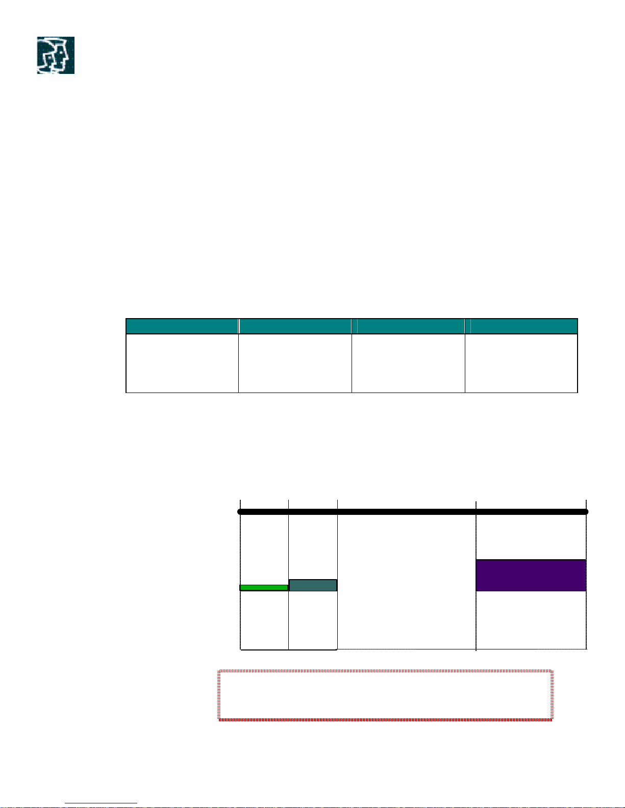
5.15 5.35
5 GHz UNII
Conducted Power
Antenna
Radiated
UNII-1: Indoor Use, antenna must be fixed to the radio
UNII-2: Indoor/Outdoor Use, fixed or remote antenna
UNII-3: Primarily used for Outdoor Bridging
5.25
4Channe
UNII-1 UNII-2 UNII-3
40mW 250mW
(16dBm
6dB
22dB
158mW
4Channe
(24dBm
6dB
30dBm
1 W
5.725
4Channe
36dBm
(30dBm
6dB
Copyright © 2004 Cisco Systems, Inc. All rights reserved.
Page 4 of 53
Page 5

Figure 3. Conducted and Radiated Power Levels in UNII-1,2 & 3 Bands
Wireless systems are certified as complete systems. In the US, the FCC requires that all antennas
sold by a Wireless vendor be certified with the radio with which they are to be sold. Cisco Aironet
systems are tested and certified for each country using Cisco Aironet components. If amplifiers or
third party antennas are used, then it is likely the entire system must be recertified. Systems
integrators and installers are responsible for FCC compliance or recertification when using third
party equipment.
1.2.4 Other Regulatory Domains
In addition to FCC, other main regulatory domains for operation in 5GHz are European
Telecommunications Standards Institute (ETSI), Japan, China (Mainland China), Israel, Singapore
and Taiwan (Republic of China).
Check the Cisco web site for compliance information and also with your local regulatory authority
on what is permitted within your country.
http://www.cisco.com/warp/public/779/smbiz/wireless/approvals.html
ETSI recommended frequency band for bridging is 5.470 to 5.725 GHz offering almost eleven
channels with the same EIRP rules as FCC. In exchange of this wide spectrum, the ETSI
recommendation mandates the inclusion of two features not currently found in 802.11 products,
Dynamic Frequency Selection (DFS) and Transmit Power Control (TPC). DFS and TPC are the
two functions handled quite well by the HyperLAN2 specification. The IEEE 802.11h standard
covers both DFS and TPC that will apply to the 5 GHz band at a later date.
1.2.5 FCC Regulations regarding EIRP limitations with Point-to-Point & Point-toMultipoint Wireless Networks
Wireless bridges can be deployed to establish a direct link between two sites. The network traffic
between the two sites is bridged or forwarded to the other bridge, as if were one network. This is
called a point to point link.
Point-to-multipoint wireless links are an expansion of the point-to-point link in which one
centralized bridge can establish multiple point-to-point links. Using point-to-multipoint connection,
multiple remote sites such as buildings can be linked together into a single logical network. In a
point-to-multipoint architecture, these remote sites are linked to a single root bridge at a centralized
site.
For point-to-multipoint UNII-3 systems, the directional antenna of 6 dBi gain can be used. And if
gain is greater than 6 dBi then the peak transmit power of the device has to be reduced by amount
in dB the directional antenna gain exceeds 6 dBi.
Copyright © 2004 Cisco Systems, Inc. All rights reserved.
Page 5 of 53
Page 6

EIRP = Peak Transmit power (30dBm or 1 Watt) + 6 dBi = 36 dB (4 Watts), a constant.
Point-to-point UNII-3 systems, may employ the transmitting antennas of directional gain up to 23
dBi, without any corresponding reduction in peak transmit power. For antennas with gain greater
than 23 dBi, a dB reduction in output power is required for every corresponding dB increase in
excess of 23 dBi.
EIRP = Peak Transmit power (30dBm or 1Watt) + 23 dBi = 53 dB (200 Watts), a constant.
2 BR1400 Wireless Bridge Product Introduction
Cisco’s BR1400 Series, brings about one of the most flexible and feature rich bridging products
Cisco has ever made. It was designed to deployed quick and easily in a multitude of different
environments and for different purposes.
The BR1400 Series Wireless Bridge is designed for building to building Wireless connectivity.
Operating in the 5.8 GHz UNII 3 Band (5725-5825 MHz), derived from the 802.11a standard,
the bridge delivers 6 to 54 Mbps data rates without the need for a license.
This allows anyone to deploy FCC certified bridges anywhere in the US without applying for or
paying for special licenses (note: some restrictions may apply over special areas such as airports
and military bases). This allows for networks to be quickly deployed and then moved if necessary
without any licensing or government reporting. An example would be at an airport or Homeland
Security application where operations need to place cameras and or other data links near critical
areas. By placing a single bridge on top of a tall structure (such as a control tower) and another on
a power/light truck pointing toward the control tower, they have effectively made a full secure link.
Continuing with the scenario as often as required they could move the power/light truck and
effectively move the link through the grounds an endless number of times, each time without
worrying about trenching cables or applying for licensees.
Bridge 1400 is IOS based, and it has the following IOS features:
• Transparent bridging between the wired Ethernet and wireless 802.11a Radio Interface.
• Native Ethernet and 802.1q tagging is supported on both the wired Ethernet and wireless
802.11a Radio interfaces.
• Support for 802.1d Spanning Tree Protocol.
• Support for 802.1q Virtual LAN to work in conjunction with a Switch/Router attached to
the BR1400.
• Support for Port Aggregation Protocol (PagP) and Fast Ether Channel (FEC) providing up
to 100 Mbps of combined bandwidth, by stacking two BR1400 bridges.
• QoS support, 8 transmit priority queues are provided in IOS, with 1 queue per
802.1D/802.1p user priority value for the radio interface.
• IP TOS/DSCP based classifications are supported for classifying voice packets.
• Link level redundancy for P2P using STP.
• Security:
Copyright © 2004 Cisco Systems, Inc. All rights reserved.
Page 6 of 53
Page 7
40-bit and 128-bit WEP encryption
802.1x and LEAP
AAA Radius Server support
Enhanced Encryption Features like TKIP,MIC.
• Voice support for P2P configurations.
• Support for Cisco IP-based protocols like TCP, UDP, TFTP, FTP, ARP, ICMP, CDP,
SNMP, RADIUS, TACACS, SNTP, Telnet and NTP.
• Network management support via three interfaces: SNMP, Web Interface, Telnet/CLI.
• Support for Cisco View network management system.
• IP Address Management, supporting DHCP client/server and DNS client/server
functionality
• Provides diagnostic and statistics information, using any of the management interfaces.
• Installation Mode for aligning the antenna and setting up the ODU at the outdoor site.
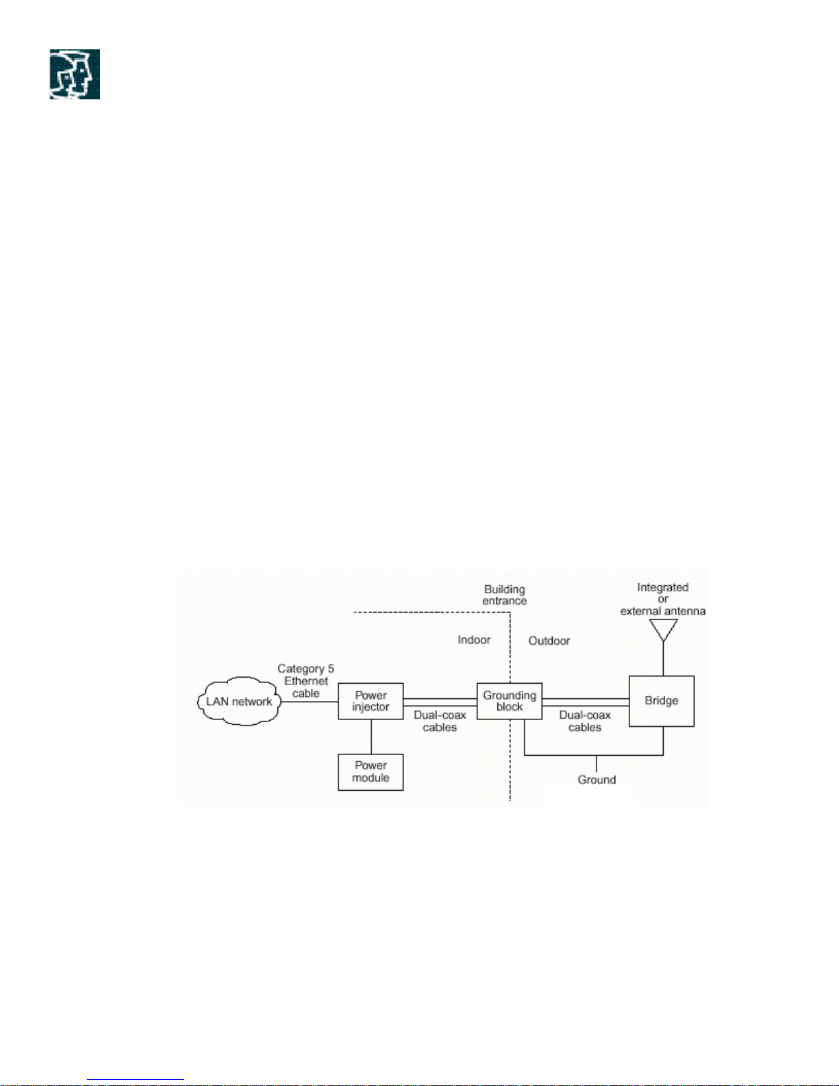
2.1 Product Overview
The system consists of a weather proof wireless bridge, a Power Injector- LR, a Power Adaptor,
a grounding block at the building entrance and optionally external antennas. The Bridge and the
external antennas, if used, are installed outdoors. The grounding Block is installed at the building
entrance and the Power Injector LR and DC power supply are installed indoors. The overall
System block diagram is shown in the Figure below.
Figure 4. Schematic of Typical Bridge Installation
2.1.1 Wireless Bridge
The BR1400 wireless bridge includes all the RF and Digital Radio circuitry including four external
interfaces:
1. A pair of 75 ohm F-type coaxial connectors for Power Injector LR interface functioning as
100 Mbps Ethernet communication port and DC power input.
2. Radio interface, which includes a directional captive antenna or an N-type RF connector
for a remote antenna.
Copyright © 2004 Cisco Systems, Inc. All rights reserved.
Page 7 of 53
Page 8
3. RSSI voltage port for antenna alignment
4. Four LEDs providing system status and antenna alignment feedback.
Due to its rugged design, the BR1400 Series Bridge is designed primarily for outdoor deployments.
Unlike other equipment where special care needs to be taken to carefully protect the equipment
from the elements such as wind, rain and other weather conditions such as extreme temperature
gradients on both ends of the spectrum, the BR1400 series was designed with this exact problem in
mind. The BR1400 is plenum rated eliminating the need to have additional NEMA or other
weatherproof enclosures and can operate in temperatures ranging from -22°F all the way to 131°F
without any external temperature influencing devices. The entire unit is designed to withstand and
still operate in severe conditions including very high wind and precipitation of all types.
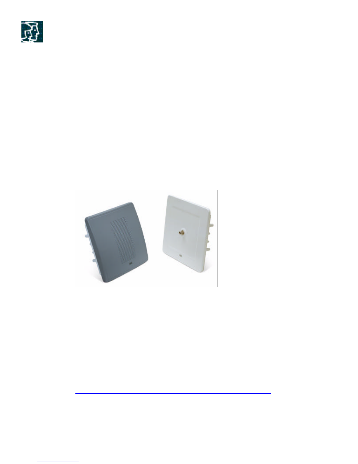
The BR1400 wireless bridge is available with highly directional captive (built in) antenna. The gain
of captive antenna is 22.5 dBi. We also have an option for connecting external antennas under a
different SKU where it provides an N-type RF connector for interfacing to various external
antennas for greater range and flexibility.
Figure 5. AIR-BR1410A -A-K9 and AIR-BR1410A-A-K9-N
Please note the Radome provides an environmentally sealed enclosure and is not removable from
the housing. Therefore, you should plan in advance about what type of network you want to
deploy, as these SKUs are not interchangeable in the field. If you wish to use high gain antennas for
longer range or perhaps an Omni antenna for multi-point operation you may need to order the
SKU on the right of the picture above.
In addition to the conventional role of the radio in the bridge as “Root” or “Non Root”, BR1410
has more roles in radio network which facilitates the installation and alignment. Observable LEDs
and the voltage port can be used for alignment, so one does not need a laptop or any other
conventional tool for installing these bridges. Please refer to the documentation for BR1410
available on our website:
http://www.cisco.com/en/US/products/hw/wireless/ps5279/index.html
2.1.1.1 Antennas for the BR1400
Copyright © 2004 Cisco Systems, Inc. All rights reserved.
Page 8 of 53
Page 9
The antennas listed here are available as optional remote antennas for the BR1400. The Beamwidth
and the gain of the antennas are mentioned in the Tables below.
Part Number Description
AIR-AN58G09VOA-N 5.8 GHz 9 dBi Non-Diversity Omni Vertical Polarization Ant with N-Type Connector
AIR-AN58G10SSA-N 5.8 GHz 10 dBi Non-Diversity Symmetric Sector Antenna with N-Type Connector
AIR-AN58G28SDA-N 5.8 GHz 28 dBi Non-Diversity Symmetric Dish Antenna with N-Type Connector
Table 2. External Antennas for BR1400 Wireless Bridge
Antenna Horizontal Beamwidth (degrees) Vertical Beamwidth (degrees)
Integrated (Captured) 12.0 10.0
Omni 360 6 +/- 0.5
Sector 60.0, minimum 60.0, minimum
Dish 5.7 6.0
Table 3. Beamwidths of the Antennas
Please refer to the installation section in the BR1400 manual for details about which antennas may
be used.
2.1.2 Power Injector-LR (Long Reach)
The Power Injector -LR is a self-contained functional unit suitable for indoor installation. It provides a
100 Base-T Ethernet link between the In-building LAN and the outdoor wireless unit (ODU). The
main functio n of Power Injector is to provide power onto the Ethernet connection to the ODU. The
Ethernet connection to the ODU is via two 75-ohm coax cables, the coaxial cables can be RG6,
RG59 or higher quality 75-ohm cable with a maximum length up to 100 meters. The indoor connection
to the local LAN uses standard category 5 twisted pair copper and can provide connectivity at lengths
up to 100 meters. The Power Injector is powered by the power ada pter and supplies the DC voltage
into both coaxial cables powering the ODU.
Please note that these coaxial cables do not carry any RF (radio frequency) energy. All the RF is
contained within the Outdoor Unit or Bridge.
The Power Injector has three external interfaces:
1. RJ45 connector for internal 100 baseT LAN interface.
2. A pair of 75 ohm F-type coaxial connectors for 100 baseT interface to the wireless bridge
(ODU).
3. DC power connector interfaced to the power adapter.
Copyright © 2004 Cisco Systems, Inc. All rights reserved.
Page 9 of 53
Page 10
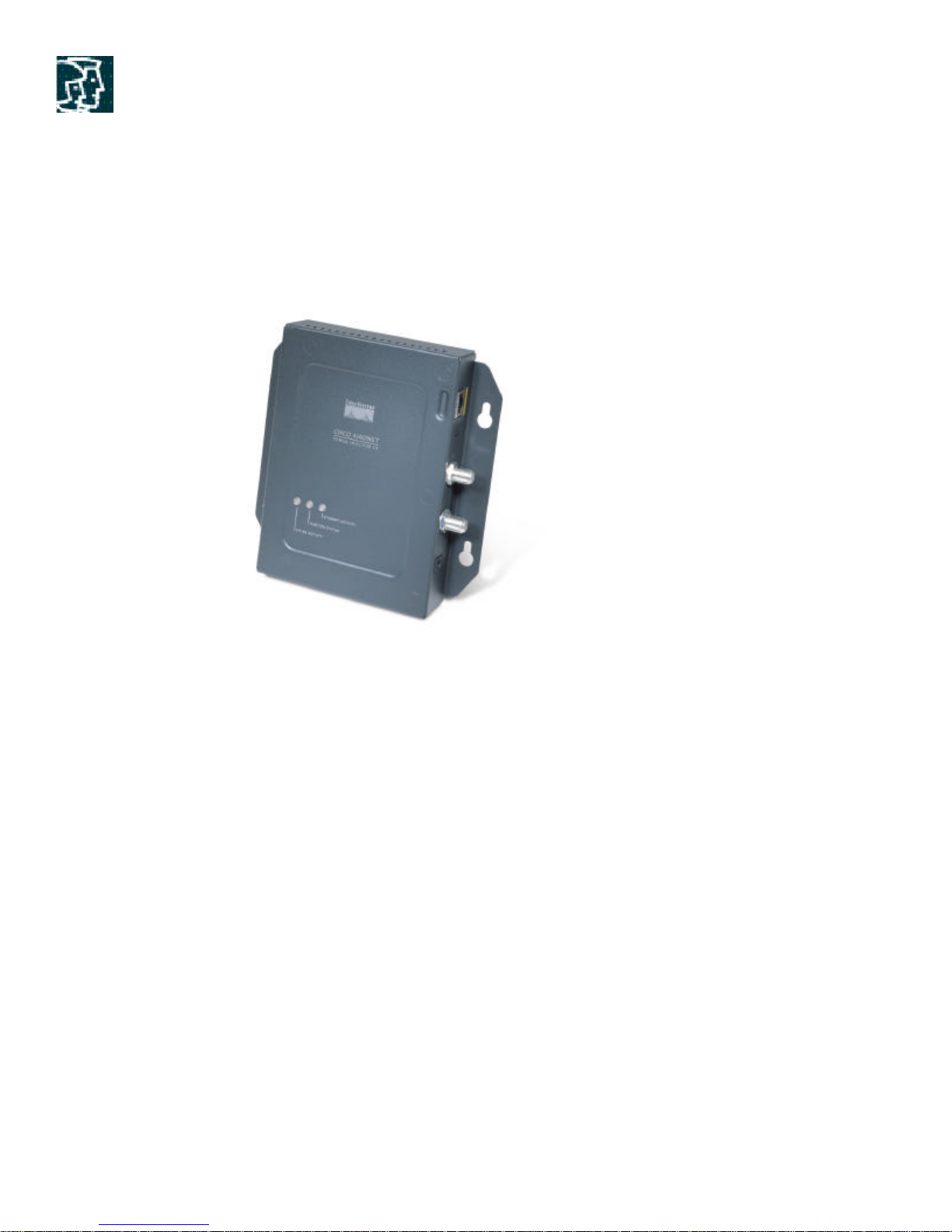
Three LEDs are included on the front power injector as shown in the figure below. They indicate
Ethernet activity, Injector Status and Uplink activity. There is a fourth LED (on the side of the box)
indicating DC power from the power adapter.
Figure 6. Power Injector-Long Reach
2.1.3 Power Adaptor
Power Adaptor provides +48V DC to the power injector. It is rated to deliver 60 W of DC
power. It has two interfaces:
1. DC output through a short cable via a barrel style power connector .25 OD (center
positive) interfacing to Power Injector
2. Universal AC input connector to be plugged into an AC power cord.
2.1.4 Grounding Block
Grounding block (Cisco provided) should be installed inline with 75 ohm coax cables at the
building entrance providing lightning protection. It has straight through F-connectors where the
shield is connected to the body of the block. This type device is commonly available for CATV
type usage by third party vendors.
Copyright © 2004 Cisco Systems, Inc. All rights reserved.
Page 10 of 53
Page 11

2.2 Bridge 1400 Low Power version
There are different SKUs with different power levels for different parts of the world in accordance
with the regulatory domains respective to these countries.
Refer to the following URL:
www.cisco.com/go/aironet/compliance
We can broadly classify the SKUs as High Power and Low Power versions. The SKU for
America and Canada is a High Power version with ability to radiate at maximum output power of
24 dBm. The part numbers for these two SKUs are AIR-BR1410A -A-K9 and AIR-BR1410AA-K9-N as discussed earlier.
In low power version we have three different SKUs as below:
1. AIR-BR1410A-E-K9
• Available Tx Power Settings: 4 & 7 dBm
• Antenna Gain: 22.5 dBi
• Anticipated Countries: Ireland, China, Malaysia, Venezuela
2. AIR-BR1410A-K-K9
• Available Tx Power Settings: 12, 15, 18, 21, & 22 dBm
• Antenna Gain: 20 dBi
• Anticipated Countries: Korea
3. AIR-BR1410A-Z-K9
• Available Tx Power Settings: 4, 7, 8, 9, 10, & 13 dBm
• Antenna Gain: 22.5 dBi
• Anticipated Countries: Australia and New Zealand
All these Low power SKUs operate in the same frequency band as high power SKUs i.e,
complete UNII 3 band. Should the installer wish to deploy point-to-multipoint networks using
Omni or Sector Antennas in these countries then High power SKU AIR-BR1410A -A-K9-N
may be ordered, check with your regulatory agency.
High gain dish antenna with 28 dBi is not supported in any of the above countries.
The outdoor range calculator can be used to determine distances with these Low power
SKUs.
3 Applications
Although we have covered several features of the BR1400 Series, we will now discuss some of the
features and functionality used in major Bridging applications.
3.1 VLANs
A VLAN is a group of end stations with a common set of requirements, independent of their
physical location. A VLAN has the same attributes as a physical LAN but permits you to group
end stations together even if they are not located physically on the same subnet.
Copyright © 2004 Cisco Systems, Inc. All rights reserved.
Page 11 of 53
Page 12
802.1q Virtual LAN support is provided to work in conjunction with the Switch/Router attached to
the 1400 series wireless bridge. Both the wired Ethernet and wireless Radio interface supports
VLAN Trunking. Native Ethernet and 802.1q tagging is supported on both the Ethernet and Radio
interfaces.
ISL tagging, VTP and DTP are not supported in BR1400. The BR1400 treats VTP message like
any other multicast message and Transparently Bridges it across.
Thus, the Bridge participates in the 802.1d (spanning-tree) process of bridging two networks
together. You extend VLANs into a wireless LAN by adding IEEE 802.11Q tag awareness to the
bridge. VLAN 802.1Q trunking is supported between root and non-root bridges through the
bridges’ primary SSID.
The basic wireless components of a VLAN consist of two or more bridges communicating using
wireless technology. The bridge is physically connected through a trunk port to the network VLAN
switch on which the VLAN is configured. The physical connection to the VLAN switch is through
the bridge’s Ethernet port.
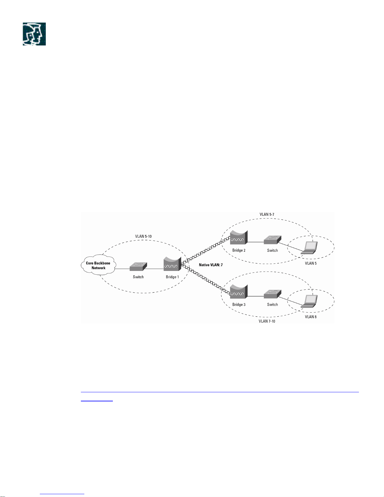
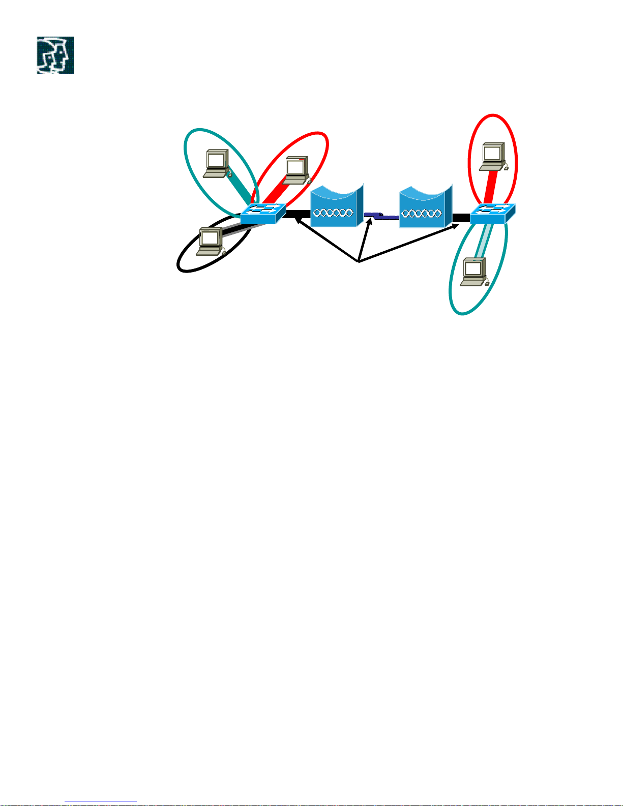
Figure 7. VLANs trunked through the wireless bridge links
In fundamental terms, the key to configuring a bridge to connect to a specific VLAN is by
configuring its SSID to recognize that VLAN. Since VLANs are identified by a VLAN ID, it
follows that if the SSID on a bridge is configured to recognize a specific VLAN ID, a connection to
the VLAN is established.
The bridge supports only one infrastructure SSID. You should assign that SSID to the native
VLAN. For more information, please consult the VLAN deployment Guide at this URL:
http://www.cisco.com/en/US/products/hw/wireless/ps430/prod_technical_reference09186a00801
444a1.html
Copyright © 2004 Cisco Systems, Inc. All rights reserved.
Page 12 of 53
Page 13
NATIVE VLAN
D
VLAN 12
Station_A
Station_B
Station_C
Switch_1
VLAN 14
Infrastructure ssid: native VLAN
Figure 8. VLAN CONFIGURATION
VLAN 11
Root
802.1Q Trunk
100Mbps,
VLAN 11
Station_
Non-Root
Switch_2
Station_E
VLAN 12
The main steps to configure the VLANs are:
1) Enable 802.1q trunking on the wired network: On either side of the Link you should console into
the Ethernet port of the Switch to which Bridge is connected and give the following commands:
Interface FastEthernet0/1
Switchport trunk encapsulation dot1q
Switchport mode trunk
Please note that you must have 100 Mbps Ethernet connections between the switch and
the Bridge.
2) Enable 802.1q trunking on the Bridges: Specify the VLAN-id X as the native VLAN on the
root and non root bridges by going into the GUI services and clicking on VLAN.
Copyright © 2004 Cisco Systems, Inc. All rights reserved.
Page 13 of 53
Page 14
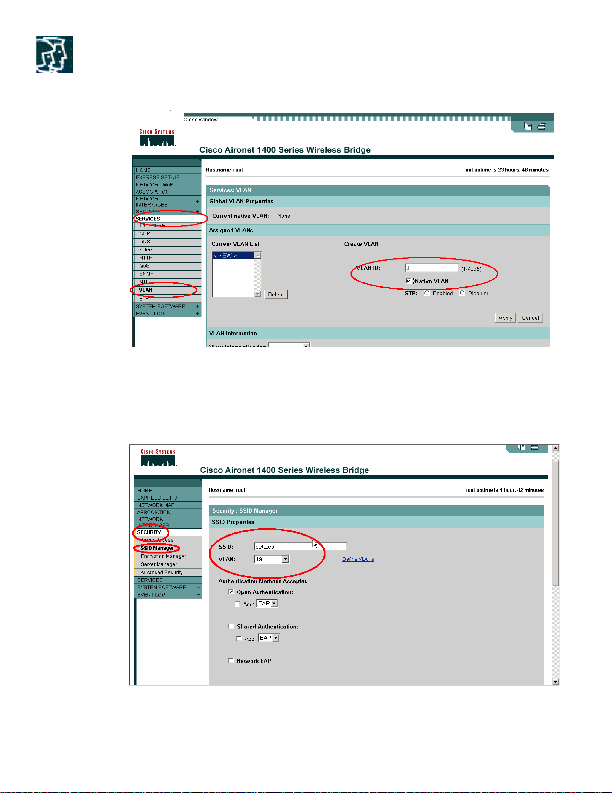
Figure 9. Screenshot for VLAN configuration
3) Mapping: Map the native VLAN to the Bridge SSID. For this use the GUI interface and go to
Security and click on SSID Manager. Map the SSID to VLAN X.
Figure 10. Screenshot for VLAN configuration
Copyright © 2004 Cisco Systems, Inc. All rights reserved.
Page 14 of 53
Page 15

4) Add the VLANs: Add the VLANs defined on the switches to the Root and Non Root Bridges.
Like for the above figure, VLANs 11, 12 and 14 have to be added on the Bridges as well, so that
these VLANs can be trunked through the wireless link.
3.2 QoS
Implementing QoS in your wireless link makes network performance more predictable and
bandwidth utilization more effective. By using QoS feature you can prioritize a specific type of
traffic instead of making it a purely FIFO (first in, first out). This is due to the fact that voice/video
traffic when subject to delays causes very unfavorable behavior in phone conversations (major lags
or even dropped phone calls). This is also true with other types of traffic such as video traffic
(which is what we will be testing here in this situation).
The following are the objectives of the QoS feature supported in 1400 bridge:
• Provide 802.1p priority bits and 802.1q VLAN tag based QoS
• Provide priority services for VOIP traffic, based upon IP TOS/DSCP
The bridge can only classify traffic based on IP TOS (Type of service bits in IP protocol header)
Precedence and DSCP (differentiated services code point) values and put it into the correct priority
queues. It has 8 priority queues corresponding to eight 802.11E priority values. The CoS values
associated with the eight priority queues are the same as the 802.1d
User priority values that are carried in an Ethernet frame, an 802.1q priority tag or an 802.1q
VLAN tag. The CoS value is used to select the appropriate 802.11 transmit queue.
The bridge uses the radio traffic class definitions to calculate back off times for each packet. As a
rule, high-priority packets have short back off times. The default values in the Min and Max
Contention Window fields and in the Slot Time fields are based on settings recommended in IEEE
Draft Standard 802.11e.
We can modify the CwMin and CwMax values depending upon the type of the network and our
needs.
QoS works even with packet concatenation enabled.
The steps to configure QoS are:
1) First create a QoS policy. Go to services in GUI interface and define a policy.
Copyright © 2004 Cisco Systems, Inc. All rights reserved.
Page 15 of 53
Page 16
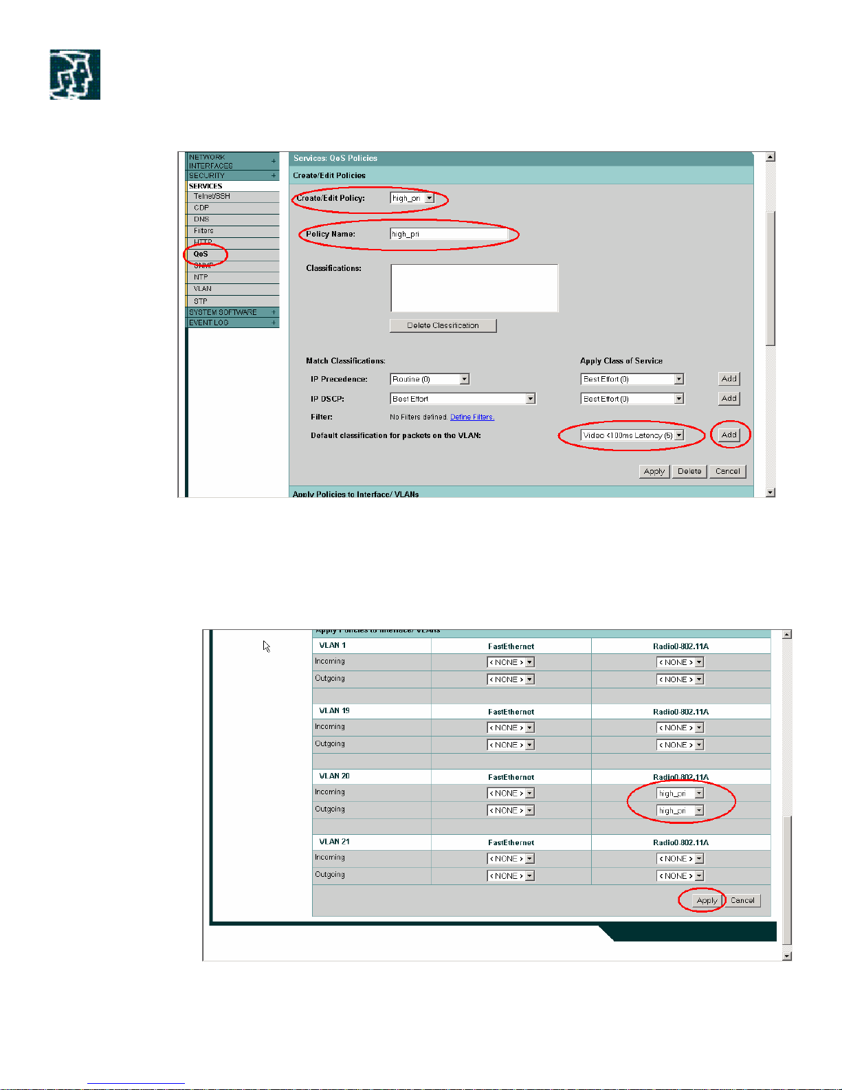
Figure 11. Screenshot for QoS configuration
2) Apply the policy: You can apply the policy to the VLAN configured on the bridge. If you
do not use VLANs on your network, you can apply your QoS policies to the bridge’s
Ethernet and Radio ports.
Figure 12. Screenshot for QoS configuration
Copyright © 2004 Cisco Systems, Inc. All rights reserved.
Page 16 of 53
Page 17

3.2.1 Voice over IP
Using the QoS feature, voice traffic can be prioritized by defining a policy and assigning that policy
to the VLAN carrying the voice traffic.
At this time, the 1400 series Bridge supports voice only in P2P links. Voice in a P2MP
configuration is limited and has not been fully tested yet, however; it will support some number of
simultaneous voice calls as it has the same QoS mechanisms as point to point networks. Keep in
mind, since there is no over the air QoS coordination between end points, it will not be as efficient
as point to point network. Voice in P2MP networks will be possible when PCF mode is
implemented down the line.
The maximum number of voice lines for P2P links in the table below. The number of voice calls
shown in the table has been taken along with the data traffic running in the network. Number of
voice lines has been calculated by setting a maximum jitter bound of 25 ms. This cannot be
guaranteed for 6 and 9 mbps rates. For P2P links supporting voice those rates needs to be
disabled or the voice quality will be poorer depending on the rest of the network architecture.
Rate (Mbps) # Calls G.711 # Calls G.729
54
48
36
24
18
12
9
6
15 44
15 44
15 44
15 44
15 44
15 44
NO SUPPORT NO SUPPORT
NO SUPPORT NO SUPPORT
Table 4. Maximum number of calls for P2P for G711 and G729 codec (jitter<25 ms)
3.3 Security
Security is a major part of any enterprise deployment and as such Cisco has spent quite a bit of
time on ensuring the security of not only the wireless links as a whole but also the Bridge itself.
Multiple types of security levels are available on 1400 Series Bridge.
Configuring your own SSID on the 1400 Bridges provides a rudimentary level of security. 1400
Bridge also provides different type of encryptions on the data going across the link, like Static
Wired Equivalent Privacy (WEP), Dynamic WEP using LEAP, TKIP (Temporal Key Integrity
Protocol) and MIC (Message Integrity Check). 1400 wireless bridge supports Cisco Wireless
Enhanced Authentication Protocol (LEAP). LEAP is a Cisco proprietary implementation
conforming to the IEEE 802.1x Draft Security Standard for port-based network access control.
LEAP authenticates the user and assigns a new WEP key every time a client associates or
Copyright © 2004 Cisco Systems, Inc. All rights reserved.
Page 17 of 53
Page 18

reassociates with an Access Point or a Bridge. 1400 Bridge can behave as a LEAP client in slave
mode (Non Root) or LEAP authenticator in Master mode (Root) as shown in the figure below.
Figure 13. Leap in a bridge link
LEAP requires a LEAP compliant Remote Authentication Dial-In User Service (RADIUS) server
such as Cisco Secure ACS 2.6 (or later) to operate. LEAP is a mutual authentication scheme (of
Client and Radius Server). The challenge-response mechanism uses the user’s password as the
shared secret. In a Microsoft Network environment, a user’s Domain id and password can be
used. Leap can be used with wide variety of platforms. No native EAP support is currently
available on Legacy operating systems.
The main steps to set up the bridge link with Leap are:
1) Configure the ACS server with a unique IP address. Make sure that you can ping ACS
server from the Root Bridge.
2) Configure the ACS server with an AAA client with the Root Bridge’s IP address and the
appropriate shared secret password. Please refer to the LEAP configuration Guide for
setting up the ACS. The Link is:
http://www.cisco.com/warp/public/cc/pd/witc/ao1200ap/prodlit/wrsec_an.htm
3) Add a user account (user-id and password) on RADIUS server (ACS) for Non Root
authentication. Example: user-id = non-root, password=non-root.
4) Enter the parameters for RADIUS server in the Root Bridge. Use the GUI interface and go
to Server Manager in the security section to do this.
Copyright © 2004 Cisco Systems, Inc. All rights reserved.
Page 18 of 53
Page 19

Figure 14. Screenshot for configuring Security
5) Configure Non Root Bridges with a user-id/password (for example: non-root/non -root) for
LEAP authentication to the root bridge using ACS. In GUI interface go to SSID manager
in Security section to do this.
Copyright © 2004 Cisco Systems, Inc. All rights reserved.
Page 19 of 53
Page 20

Figure 15. Screenshot for configuring security
6) After completing the above steps, view the association table of the root bridge to ensure all
non root bridges are associated.
7) Enable TKIP & MIC if you want enhanced encryption in your link.
4 Feasibility Study
This section will provide the reader with an understanding of what is required to determine if a
successful bridge link can be accomplished.
When determining the suitability of a successful bridge link, one needs to define how far the Bridge
link is expected to transit and at what radio data rate. Very close bridge links one Kilometer or less
are fairly easy to achieve assuming there are no obstructions referred to in radio jargon as a “Clear
Line Of Sight” or LOS.
If both buildings are very close, a link might be attained from a window by using one of the upper
floors of the building avoiding the need to install a bridge outdoors. This might be fine for a
temporary event or in a pinch to get a link up when time or weather conditions don’t allow for a
more permanent solution. Keep in mind some windows can have metallic flakes inside the glass for
tinting or perhaps conductive gas for insulation to prevent fogging such materials may impede
(attenuate) the radio signal preventing such a link.
Tip: Links through glass are not a preferred method but could work for very short links.
Copyright © 2004 Cisco Systems, Inc. All rights reserved.
Page 20 of 53
Page 21

Figure 16. It is possible to create a nearby bridge link through a window
4.1 Determining Line of Sight
Since radio waves used by the BR1410 are very high in frequency (5.7 GHz / 5700 MHz) the
radio wavelength is really small, therefore; the radio waves don’t travel nearly as far given the same
amount of power as radio waves on lower frequencies. This higher frequency range makes the
Bridge ideal for unlicensed use as the radio waves do not travel far unless a high gain antenna is
used that can tightly focused the radio waves in a given direction.
Tip: High gain antennas can focus radio waves allowing them to go much further similar to
adjusting the focus of a flashlight from a flood type light into a tight beam.
Figure 17. Line of Sight disappears at 6 miles (9.6 Km) due to earth curve.
The higher the frequency used the more dependent you are upon line of sight, and the BR1400
Bri dge using 5.7 GHz requires line of sight for successful operation. As the low powered radio
signals degrade over distance, this is known as free space path loss or simply path loss. It difficult
to acquire and sometimes easy to lose a bridge link when attempting to transmit radio waves
Copyright © 2004 Cisco Systems, Inc. All rights reserved.
Page 21 of 53
Page 22

through objects such as trees, foliage, hills or other buildings as these objects can absorb or reflect
radio signals away from the intended target. Distances greater then 6 miles (9.6 Km) generally
require radio towers or high locations to overcome the Line of sight obstruction caused by the
curvature of the earth.
Technical jargon: As the Bridge signal propagates from the antenna, its power level decreases at
a rate inversely proportional to the distance traveled and proportional to the wavelength of the
signal, this is known as FSL “Free Space Loss”. This variable is used in the Cisco outdoor Bridge
range calculation utility to determine the maximum distance a Bridge link can go.
Although one can use a GPS (Global Positioning System) and or a topographical map to determine
if there are any hills or obstructions in the way, it is always best to first visit the site and physically
examine the site to determine if you can see the sites you wish to link together. This can answer a
lot of questions you may have, but you may have to go on the roof of the building or up in a bucket
truck to successfully perform this task.
Once you are on the roof or other high location look around see if you can spot the site(s) you wish
to link. If the site is behind trees or other obstructions a tower may be required. To determine if a
tower is required, a very low tech method is to simply tie a few helium balloons together with some
kite string. The low cost helium foil type balloons available at any party shop work best and can be
easily floated above nearby objects. Binoculars or a telescope may be required to observe more
distance links. Strobe lights could be used instead of balloons if this task is done at night or from the
top of a building roof. Another method of spotting would be to raise a bucket truck or use a vehicle
with a telescoping mast.
Tip: Measuring the string used to float your “spotter balloon” would give you an idea how
high a radio tower or other structure would need to be to support your Bridge.
Figure 18. It is easy to link any or all of these nearby buildings together
If you can see all the sites, installing the links is simply a matter of determining the distances and
data rates desired. If you can not see the building that you wish to link due to trees or other objects
then you might be able to install or use a nearby radio tower to get above the obstruction. Another
Copyright © 2004 Cisco Systems, Inc. All rights reserved.
Page 22 of 53
Page 23

perhaps less costly approach might be to find a location that both sites can see, for example, some
communiti es use their water tower or a nearby mountaintop for this purpose. If you have access to
such a location, you could install another Bridge or Bridge pair using that site as a relay point.
Once you have determined that Line of Sight is possible, you are now ready to determine if the
bridge link is possible given data rate and coverage distance required.
Tip: Topographical maps can be found at airports, flight schools and libraries.
4.2 Environmental Issues
Now that we have discussed how free space path loss (FSP) and line of sight (LOS) can affect the
distance of a bridge link lets examine a few other variables that can degrade a bridge link.
Weather – Rain, Snow, Fog and other weather climates with high humidity can slightly obstruct or
affect our line of sight introducing a small loss (sometimes referred to as rain fade or simply fade
margin) but generally this has little effect on our bridge link. If you have established a good stable
bridge link this is not a problem, however; if the link was poor to begin with then bad weather
could degrade performance or cause loss of link.
Tip: Cisco Outdoor Bridge Range Calculation Utility allows you to choose your Climate and
Terrain allowing the program to compensate for any degradation in weather.
4.3 Fresnel Zone
An imaginary ellipse around the visual line of sight between the transmitter and receiver. As radio
signals travel through free space to their intended target, if the radio waves encounter an obstruction
in the Fresnel area the signal can be attenuated (degraded) sometimes severely. Best performance
and range is attained when there is no obstruction of this Fresnel area. While this is not always
unavoidable, generally links can still be made so long as 60-70 percent of the Fresnel area is
unobstructed.
Figure 19. Fresnel Zone is an ellipse (desired clearance) surrounding the radio path
Copyright © 2004 Cisco Systems, Inc. All rights reserved.
Page 23 of 53
Page 24

Figure 20. Avoid links that have obstructions in the Fresnel Zone
Figure 21. To resolve Fresnel Zone issues raise the antenna or remove the
obstruction
To improve a Fresnel zone obstruction you need to get above the obstruction which usually means
you need to get the antenna mounted higher. This may be a simple matter of mounting the antenna
at another point of the building such as an elevator room or other structure higher on the buildings
roof. If no such structure exists, consider using a taller mast pipe or determine if another nearby
building or structure would work better. If this Bridge is located on a radio tower you may want to
mount it higher on the tower or determine if more suitable tower exists. If a tree or other
obstruction is under your control perhaps you can remove it.
Technical jargon: It is possible to calculate the radius of the Fresnel zone (in feet) at any particular
distance along the path using this equation:
F1= 72.6 X SQR (Distance/4 X Frequency in GHz)
Where F1=the first Fresnel zone radius (ft.). D=total path length (mi.). f=frequency (GHz)
Note: Fresnel zone, Free Space Loss, antenna gain, cable loss, data rate, link distance, transmitter
power, receiver sensitivity along with other variables that all play a role in determining how far your
bridge link will go.
Copyright © 2004 Cisco Systems, Inc. All rights reserved.
Page 24 of 53
Page 25

Height =
D2/8 + 43.3
√
D/4F
43.3√D/4F
60% first Fresnel
D = Dis
tance between Antennas
Earth bulge at midpath
H2=D
2
/6
Tip: Forget the math, calculating bridge links is easy as these variables are calculated with
the simple to use Cisco Outdoor Bridge Range Calculation Utility that we will discuss later
in this paper.
Normally 60 % of the first Freznel zone clearance is recommended. So the above formula for 60%
Freznel zone clearance can be expressed as:
0.60 F1= 43.3 x SQR (distance/4x Frequency in GHz)
These calculations are based on a flat terrain. Since the earth i s not flat, earth curvature should be
taken into account when planning for paths longer than six miles.
H =
H1
+
H2
H1 = 43.3 √ D/4F
H1 = Added Antenna Height for 60% Freznel Zone Clearance in feet
H2= Added Antenna Height for Earth Bulge Clearance in feet
Where,
D is the Path Length in miles
F is the frequency in GHz
Figure 22. Freznel Zone and Earth Bulge Clearances
The table below can be used to determine how much Fresnel zone clearance in feet is
recommended for a particular path length in miles.
Copyright © 2004 Cisco Systems, Inc. All rights reserved.
Page 25 of 53
Page 26

Table 5. Fresnel Zone Clearance in feet for a particular Path Length
4.4 Determining the coverage distance required
Determining the coverage distance in a strictly point to point Bridge link is easy. A Point to Point
Bridge link is one in which only two locations are connected.
Figure 23. Point-to-Point Bridge Link
As you can imagine, when linking only two sites your antenna choices become easier as you only
need to concentrate your radio signal in one direction at the target Bridge and vice versa. When
two or more Bridges are used the primary Bridge is identified as the Root or main site while the
other sites are designated as Non-Root sites.
When operating in Point to Point mode the 1400 series Bridge can be ordered with an integrated
22.5 dBi antenna making it a simple one piece outdoor unit. The Point to Point range with the
integrated antenna is 7.5 miles at 54 Mbps or up to 16 miles at 9 Mbps.
The integrated antenna is the most popular choice as this can be deployed rapidly and easily
assembled as a one piece installation on a building or tower.
For longer range up to 12 miles at 54 Mbps or 23 miles at 9 Mbps the bridge could be ordered
with the optional higher gain and slightly larger 28 dBi external dish antenna.
Copyright © 2004 Cisco Systems, Inc. All rights reserved.
Page 26 of 53
Page 27

When more then two buildings need to be connected together the installation gets slightly more
complicated. This is referred to as a Point to Multi-Point link.
Figure 24. Point to Multipoint Bridge Link
When linking more then one building, like in the Point to Point link we have defined a Root Bridge
and all the other sites in the multi-point link take on the role as Non-Roots Bridges. A Non-Root
Bridge will always try to initiate a link to the Root.
Unlike the Point to Point link, the Root Bridge now needs to transmit in more then one direction in
order to establish a radio path with the other three Non-Root bridges. Directional antennas that we
described in the Point to Point links are not practical for the Root Bridge unless all three Non-Root
sites were in a straight line as the coverage pattern of a directional antenna only transmits a narrow
beam in a given direction.
In this application we could use a 1400 series Bridge that supports the use of remote antennas and
then use an Omni-Directional antenna on the Root Bridge which then transmits radio signals in all
directions. Since the radio signal would be going all directions this comes at a price since it is not
possible to transmit the energy nearly as far as it could if it was able to focus the energy in only one
direction. The remote Non-Root bridges can however focus their energy to the Root so directional
antennas may be used, therefore; performance degradation with respect to distance will occur
primarily at the Root.
Using the Cisco 9 dBi Omni hub antenna on the Root Bridge in communication with a Non-Root
sites using a 22.5 dBi integrated antenna a distance of 2 miles at 54 Mbps or 8 miles at 9 Mbps
could be achieved. If these distances were not long enough, each bridge has several nonoverlapping channels allowing for additional Bridges to be added creating a hybrid approach where
one or more Bridges could be used creating a Point to Point link while others could be configured
for Point to Multi-Point linking the closer sites.
Copyright © 2004 Cisco Systems, Inc. All rights reserved.
Page 27 of 53
Page 28

Figure 25. Site 1 and two are linked via Point to Point for greater distances
Tip: The majority of Bridge links are done from building roof tops saving the expense of a
radio tower and professional climber or bucket truck.
Figure 26. Different Antenna options for use with Bridge 1400 series
As the radio energy is focused using different antennas the coverage pattern or angle in which of the
radio signal propagates changes, this is known as the antenna beamwidth. When using the 9 dBi
antenna it will transmit with a horizontal beamwidth of 360 degrees going in all directions, this will
certainly cause the radio waves to disperse the power in all directions therefore it would not go
nearly as far as say a 28 dBi dish antenna with a narrow beamwidth of only 5.7 degrees.
Copyright © 2004 Cisco Systems, Inc. All rights reserved.
Page 28 of 53
Page 29

Tip: Don’t get Beamwidth confused with polarity which is the orientation of the antenna.
Technical Jargon: Beamwidth is defined as a measure of the ability of an antenna to focus radio
signal energy towards a particular direction in space. Beamwidth is usually expressed in degrees
HB being Horizontal Beamwidth usually the most important one with VB being the Vertical
Beamwidth (up and down) radiation pattern. When viewing an antenna plot or pattern, the angle is
usually measures at half-power (3 dB) points of the main lobe when referenced to the peak
effective radiated power of the main lobe.
Figure 27. W hen linking buildings of different heights, the antenna on the higher
building should be aimed downward to compensate for the height disparity and
vice versa.
4.5 Using the Outdoor Bridge Range Calculator
The Cisco Outdoor Bridge Range Calculation Utility was written using Microsoft Excel so the user
is able to see exactly how the calculations are performed. This utility supports Wireless Bridge links
using Cisco 2.4 GHz (BR-350 Series Bridges) as well as the Cisco 5.7 GHz (BR-1410 Series
Bridges).
There are many variables that affect the overall distance of a Bridge link; let’s define the variables
used in the Outdoor Bridge Range Calculation Utility.
1. Regulatory Domain - Depending on which country you are located in, your Cisco Bridge
product may have different frequencies, power or performance settings designed to
conform to the regulatory body responsible for radio communications in your country.
2. Bridge Model Number – This gives you a choice to select the Bridge model either with
integrated antenna or the Bridge model with a remote antenna. Each model number has
different power level settings and antenna options, depending upon the regulatory domain
selected. One can select a model number available which best suits one’s needs with
regards to mounting options available, length of the wireless link, etc.,
Copyright © 2004 Cisco Systems, Inc. All rights reserved.
Page 29 of 53
Page 30

3. Power Level – This is the transmitter power setting and is configurable so that the power
can be set appropriately when using higher gain antennas or configuring for really short links
that don’t need or require the maximum transmitter power.
4. Data rate – This is the radio data rate, as the data rate is configured to a lower value the
Bridge receiver sensitivity increases permitting further distances.
5. Antenna – When a directional antenna is used, it can focus the radio energy into a
particular direction (known as gain and is expressed in dBi).This value in dBi represents the
increase over an isotropic or (zero gain) antenna. Generally speaking, the lower the gain the
lower the distance and less directional the signal is.
6. Other Antenna – Allows you to manually enter the gain of a non-Cisco antenna or one
that does not appear in the drop down options.
7. Cable Loss / Length – Cisco antennas at 5 GHz have 4.9 Ft of cable and are designed to
connect directly to the 1400 Series Bridge. Should you wish to add to this cable length (not
recommended) you can enter in the loss of the non-Cisco supplied cable as well as the
length.
8. Effective Isotropic Radiated Power – Displayed so the installer can verify compliance
with their countries rules and regulations.
9. Environmental conditions – Allows terrain and atmospheric conditions to be defined so
they can be considered in the distance calculation.
10. Maximum Distance – Displayed in Miles and Kilometers
11. Earth Bulge at above distance – Given a distance this will display how much line of sight
disappears due to the curvature of the Earth. Displayed in Feet and Meters.
12. Fresnel Zone Clearance – Given the distance this is the height of the actual Fresnel Zone.
Displayed in Feet and Meters.
13. Required Antenna Height Above Obstructions – Given Earth Bulge, and estimated
Fresnel Zone Clearance this is how high the antennas should be above ground. Displayed in
Feet and Meters.
14. Recommended Fade Margin – The value displayed in dB Cisco that recommends taking
into account many factors including environmental conditions.
Copyright © 2004 Cisco Systems, Inc. All rights reserved.
Page 30 of 53
Page 31

Figure 28. Cisco Outdoor Bridge Range Calculation Utility.
Using the Outdoor Bridge Calculation Utility is simple to use, to get an idea how far the Bridge link
can go, simply select the different antennas and data rates. Since all Bridge links when using the
Bridge utility are Point to Point, when computing Point to Multi-Point links always compare the
Root Bridge to each remote or Non-Root site to determine distances.
Tip: Before actually performing a site survey or ordering equipment always take a few
moments to check your distances with the utility.
4.6 Site Survey
It is recommended that you perform a radio site survey prior to actually installing the equipment. A
site survey can flush out problems such as interference, Fresnel zone issues or logistics problems
with installing the Bridges. A proper site survey should involve temporarily setting up a Bridge link
and taking some measurements to determine if your antenna calculations proved accurate and that
you have picked the right location and antenna before you spend a lot of time drilling holes, routing
cables and mounting equipment.
Tip: When power is not readily available a UPS could be used to temporarily power the
Bridge Link for a short period of time to check the radio path.
Before attempting a site survey, you should have already determined the following.
Copyright © 2004 Cisco Systems, Inc. All rights reserved.
Page 31 of 53
Page 32

Pre-Survey checklist:
1. How far is the bridge link?
2. Do I have a clear Line of Sight?
3. What is the minimum acceptable data rate the link will run at?
4. Is this Point to Point or Point to Multi-Point?
5. Do I have the right antenna?
6. Have I used the Outdoor Bridge Calculation Utility to check my figures?
7. Do I have access to both of the Bridge site locations?
8. Do I have the proper permits if any are required? Sometimes you need permission from
Union workers, electricians, contractors or the building owner.
9. Do I have a partner? Never attempt to survey or perform work on a roof or tower alone.
10. Have I configured the Bridges before I go onsite? It is always easier to resolve simple
configuration or device issues beforehand then to encounter them “on site”.
11. Do I have the proper tools and equipment to complete my task?
Tip: Cellular Phones or hand held two way radios are handy when performing surveys.
See the Bridge installation section for more tips on Surveys.
5 Interference Study
While the unlicensed spectrum offers the benefit of no licensing fees, users may pay a penalty in
terms of interference. 802.11a operates in unlicensed bands in exactly the same way as 802.11b
and earlier 900 MHz systems operate in unlicensed bands. That is, there are no restrictions on the
types of devices that operate in these bands provided that they all conform to a common set of
rules. Although not a common occurance, one could find a wireless camera, or another device
using the same frequency (channel). Changing channels usually resolves interference issues.
5.1 Possible Interference from the devices in the same band
Although the 5 GHz band is less crowded than 2.4 GHz band, over time, it is possible the 5GHz
band could become equally crowded with interference-causing devices.
The 5 GHz frequency (5725-5875 MHz) can (in theory) contain emissions from microwave ovens,
heaters, plywood laminators, medical diathermy and other non-communications devices. The FCC
allocated 5725-5875 MHz spectrum for UNII (unlicensed) usage as these very high frequencies
have a limited range and generally require line of sight, therefore; these frequencies tend to have low
interference properties. However the user must be aware that a commercial application nearby (for
example, a 10 Kilowatt Microwave oven for drying potato chips or paint) or other interference
causing electronic device nearby could disrupt communications use of that band.
Potential Interference from the bands surrounding UNII-3 band
There are many frequency bands which surround the UNII-3 band (5.725-5.825 GHz) used by
the 1400 series wireless Bridge. Should you encounter severe interference, It may be necessary to
Copyright © 2004 Cisco Systems, Inc. All rights reserved.
Page 32 of 53
Page 33

perform an interference analysis using a spectrum analyzer to make sure you have an interference
free radio link. It may also be necessary to do a link budget for the link to assure feasibility before
implementation and to know expected receive signal level before alignment of antennas to optimize
the link.
Any of the following frequencies bands may, at any time, contain high-power pulsed signals, either
ground-based or mobile. These high power signals (if in close proximity) may degrade the 1400
series receiver causing performance issues.
• 4.990-5.000 Meteorological - radio astronomy
• 5.250-5.650 Radio location (coastal radar)
• 5.460-5.470 Radio navigation - General
• 5.470-5.650 Maritime radio navigation
• 5.600-5.650 Meteorological - Ground based radar
Licensed Radio Amateurs (Ham Radio) utilize the 5.650-5.925 GHz on a shared basis with all the
above users on a secondary, non-interference basis. There are a few full-time (on the air
continually) point-to-point amateur radio microwave links that may operate in this band. These links
can be anywhere in this frequency range and are typically low power using high gain dish antennas.
Other Radio Amateur usage tends to be intermittent with usage clustered around 5760 MHz.
There are a few high-power users of this band doing moon-bounce and troposcatter
communications but again, this tends to be intermittent.
The Radio Location band from 5.250 to 5.650 GHz is shared with "Radiolocation" or radar, of
which the most active user is AWACS. Although the frequency band falls in UNII-1 & UNII-2
band range (5.150-5.350 GHz), the first and second harmonic (weaker signals) may be present in
UNII-3 band, but this airborne platform has many-megawatt ERP pulsed signal source and can
appear anytime there is an active AWACS aircraft aloft. So this could affect your wireless bridge
links should these links fall in the main beam of the radar.
Currently, there are a large number of C-band (3.7-4.2 GHz) receive-only satellite users that are
experiencing tremendous interference problems with this radar saturating their LNAs when it is in
the area. Although C-band is a bit more far away from the radio location band as compared to
UNII-3 band, since some users of C- Band have experienced some interference issues believed to
be caused by AWACS usage, it is possible that the 1400 Series Bridge links may encounter some
interference when located around and near airports.
5.2 Embedded features in 1400 series wireless bridge to fight against
interference
The 1400 Series Wireless Bridge has many features to fight for interference. To assist in resolving
interference issues, one can conduct a search for least congested channel, which is an inbuilt feature
in the bridge. Another important feature within the 1400 Series Wireless Bridge is Programmable
Clear Channel Assessment (CCA). CCA threshold can be used to decrease the receiver sensitivity
Copyright © 2004 Cisco Systems, Inc. All rights reserved.
Page 33 of 53
Page 34

• •r •e •e
PI
Dual RG6
LMR
Dual RG6
by changing the absolute receive power level above which the channel is normally considered busy.
The threshold is set to -62 dBm by default however; i t may be necessary to increase the CCA
threshold in order to allow the transmission to not appear in contention when used in a noisy
environment. CCA values can be set independently for Root and Non Root Bridge. One can also
perform a clear channel assessment by sweeping the UNII-3 band using a spectrum analyzer at the
deployment site. Always, attempt to choose the channel with the least interference for the bridge
link.
One can also adjust the Fragmentation Threshold value in the bridge, which determines the size at
which packets are fragmented (sent as several pieces instead of as one block). Use a lower setting
in areas where communication is poor or where there is a great deal of radio interference. Also one
can run the link test at every frequency and watch for signal quality, signal level and the number of
retries. Choose the best channel with good signal quality and minimum number of retries. One
should clearly understand the relation ship between signal level and quality for example; a high signal
level might have poor signal quality indicating a potential interference issue. In this scenario, one
might wish to try another channel.
6 Installation Guide
The Cisco Systems 1400 Series Wireless Bridge is designed to be installed in an outdoor
environment, typically, on a tower or a tall building. Typical types of bridge installations are shown
below.
PIM
Pwr
Grounding
Figure 29. Typical 1400 Wireless Bridge Installations
Pwr
Lightening arrestor
Copyright © 2004 Cisco Systems, Inc. All rights reserved.
Page 34 of 53
PIM
Pwr
•6
Page 35

In the above figure, the installation on the left shows the 1400 Series Bridge SKU with Integrated
antenna. Here two RG6 coaxial cables run from the Bridge to the inside of the building through the
Grounding Block. The middle and right picture depict the installation of Bridge 1400 SKU with
remote antennas. In the middle picture, the Bridge has been installed indoors and the distance
between the bridge and the antenna has been extended using LMR 400/600 cables.
Tip: Cisco does not offer LMR-400 or LMR-600 cable with N-Type connectors to extend
the distance from the bridge ODU to the antenna beyond the 4.9 ft (1.5 meter) pigtail
distance, but these are very readily available from Third Party Sources. Although you
can use the longer cable, there will be losses associated to it. So use the outdoor range
calculator carefully by incorporating the loss per feet of this cable for EIRP values.
6.1 Identifying the components
Figure 30. Cisco Aironet BR-1400 Bridge and Power Injector Cable Assembly
Copyright © 2004 Cisco Systems, Inc. All rights reserved.
Page 35 of 53
Page 36

Figure 31. Cisco Aironet BR-1400 components.
6.2 Installing the Bridges
Tip: It is a good idea to configure the bridges and verify RF connectivity before performing
the installation, this can weed out any potential configuration problems you might encounter
and perhaps save time by verifying radio connectivity before going onsite.
Survey the site where you plan to mount the bridge, some questions to ask yourself.
1. Is the mounting location structurally sound, will it hold the weight of the bridge?
2. If on the roof, try to get close to the side of the roof that you plan to transmit from
otherwise the roof itself may effect your Fresnel clearance.
3. Is a good source of ground available (for the grounding block)?
4. Is there a hole to route the cables inside the building or will you need to drill a hole? If you
do drill beware of electrical wires and pipes. Watch for sharp edges.
5. Will you need additional resources, such as a bucket truck or the services of others (some
sites require union workers or the use of electricians).
6. If a tower is used, will it handle the extra wind load and weight of the bridge? If you are
using a tower please use a professional installer to climb the tower.
Copyright © 2004 Cisco Systems, Inc. All rights reserved.
Page 36 of 53
Page 37

7. Is there a source of electrical power (assuming power is needed) for powering tools such
as drills, test equipment or for the bridge if required?
8. Always beware of electrical wires or other objects that could come in contact with the
bridge, employ or seek out a professional installer when in doubt.
6.3 Mounting the Bridges
The BR-1400 outdoor unit can be mounted directly to a user supplied mast pipe or directly to
a side of a radio tower. For larger mast pipes 2.5 to 4.5 inches in diameter the mast pipe
attaches to the outside of the bracket. For smaller mast pipes 1.5 to 2.5 inches in diameter the
mast pipe attaches to the inside of the bracket.
Figure 32. The ODU can be mounted on a large or small Mast Pipe using the supplied
bracket.
Figure 33. Optional Roof/Wall mount Kits is available.
Copyright © 2004 Cisco Systems, Inc. All rights reserved.
Page 37 of 53
Page 38

An optional Roof/Wall mount kit is available - Cisco Part number AIR-ACCRWM1400
6.4 Routing the cables
The shielded Dual RG-6 cables connect to the 1400 Series outdoor unit to the grounding block
and then finally to the Power Injector. The Bridge comes with dual 50 and 20 Ft RG-6 cables.
Typically the 20 Ft cable is used from the grounding block to the inside of the building where
th e Power injector is located. Additional cable can be purchased in 100 Ft lengths. Common
75 Ohm cable TV cable like the kind found in home appliance or electronic stores like Radio
Shack can be used if Cisco cable is not readily available.
Tip: Coaxial Cable length is limited to 100 Meter from power injector to the Bridge
When routing the cable down a radio tower one must secure the cable to the tower. This is
typically done by using plastic or nylon ties securing the cable to either one leg of the tower or
to the existing cables traveling down the tower. When using plastic or nylon ties one should
make sure the cable ties are UV (ultraviolet light) resistive so they will not crack or break from
exposure over time to the suns rays.
Always keep the coaxial cable away from sharp objects, if mounting on a roof top do not
stretch the cable across places where people will walk or move heavy equipment that might cut
or damage the cable. Always make sure the cable lies flat on the roof and never suspend it
where someone could trip over it.
Before the cable enters into the building make sure the cable is routed through the grounding
block and that care is taken to not damage or compromise the cable when routing it into the
building. Beware of sharp edges around the wire path or hole you are using to get the cables
into the building.
Tip: It is good practice to create a small cable loop around all outside connections.
Should the weatherproofing fail, this would limit the water damage to the loop
preserving the rest of the cable so that it could be spliced and reused.
Maximum cable length up to 200 meters is possible (100 meters of coax cable between Bridge
and power injector and another 100 meters of Category 5 cable between power injector and
Ethernet port).
6.5 Lightening Protection
Lightning is caused by the build up of electrical potential between the clouds and ground,
between clouds, or between clouds and the surrounding air. During thunderstorms, static
electricity builds up within the clouds. A positive charge builds in the upper part of the cloud,
while a large negative charge builds in the lower portion. When the difference between the
Copyright © 2004 Cisco Systems, Inc. All rights reserved.
Page 38 of 53
Page 39

positive and negative charges becomes too great, the electrical charge jumps from one area to
another, creating a lightning bolt. Most lightning bolts will strike from one cloud to another, but
they can also strike the ground or other metal objects. Static electricity from wind, snow or the
electrical energy from a lightning strike or nearby strike can cause damage your Bridge or other
electronic equipment.
Always use a grounding block on the BR-1400 and make sure the grounding block is attached
to a suitable ground.
Tip: Always use the grounding blocks supplied with the 1400 series bridge and take it to
a suitable ground
The grounding block is installed inline with 75 ohm coax cables at the building entrance
providing lightning protection. It has straight through F-connectors where the shield is
connected to the body of the block.
Grounding Block will bleed off any charge that builds up on outer conductor.
Power Injector and the outdoor unit have integrated lightning impulse protection at the coax
interface which will provide surge protection on the center conductors of all the F-type
connectors.
Use a heavy gauge wire and keep ground wire as short as possible. The use of a good ground
will lessen the chance of damage due to a nearby strike and helps to “bleed off” any static
charges that may build up on the cable.
Note: There is no known or guaranteed protection from a direct lightning strike.
Tip: Always keep the ground wire as short as possible and attach to a suitable ground.
Suitable grounds may include (but are not limited to):
1. Ground rod buried into the earth
2. Electrical Panel ground.
3. Building structural steel such as “I” beams
4. Professional grounding systems that may already be installed (see figure 7).
5. Metal air conditioner units (attached to the building) provided they are grounded.
6. Metal radio tower (assuming the tower is grounded), Note: Some towers especially AM
radi o towers are not grounded as the tower is actually isolated from ground as it is being
used as the antenna. This is known as a “hot” tower and you must isolate the bridge and all
grounds from this type of tower.
7. Telephone or cable TV ground.
8. If an older building is used and no plastic PVC is used, sometimes a cold water pipe
(usually copper) can be used.
Copyright © 2004 Cisco Systems, Inc. All rights reserved.
Page 39 of 53
Page 40

Figure 34. Many buildings have professional grounding systems already installed .
6.6 First time installation / linking the Bridges:
If you have not pre-configured the Bridges, you will find upon startup they will default into a
“Bridge Install & Alignment mode” and the following rules apply:
• The Station role of the bridge is “autoinstall”
• The bridge assumes a non-root bridge role and is able to associate to another root bridge
within 60 seconds after IOS is loaded
Copyright © 2004 Cisco Systems, Inc. All rights reserved.
Page 40 of 53
Page 41

• If the bridge is unable to associate with another root bridge within 60 seconds after IOS is
loaded, the bridge assumes a root bridge role.
• Radio Service Set ID (SSID) in this mode is “autoinstall”
• In Installation Mode Bridge runs link test for the RSSI value and updates the LEDs and the
RSSI voltage port.
• By default the Bridge will search for a DHCP server.
• If a DHCP server is found, the Bridge will use the assigned address.
• If a DHCP server is not found, the Bridge will become a DHCP server, and will assign
itself the address of 10.0.0.1 with a mask of 255.255.255.224.
• If the bridge is associated and it is the root bridge its default IP address is 10.0.0.1, if it is a
non -root bridge than it has been given an IP address by the root bridge and the IP address
can be found from its MAC address by browsing the root bridge association’s page or
using Cisco’s supplied IPSU utility.
• Furthermore, if the Bridge becomes Non-Root during the automatic install procedure, then
the IP address will change again to search for a DHCP server. This is done to prevent
conflicting IP address. It is assumed that if the Root Bridge will be a DHCP server and will
assign a new address.
Tip: It is suggested that you check the Cisco website for later versions of firmware and
review all documentation that came with the Bridge before installing the device.
6.7 Indoor testing - Understanding Maximum Operational Receive Level.
Should you decide to configure both bridges by Ethernet using the default address of 10.0.0.1
and assuming you have configured one Bridge to ROOT and the other to Non-Root, both
bridges will then communicate and pass data. However; should you wish to perform testing in a
lab or indoor environment and the Bridge anten nas happen to be located in very close
proximity, you could encounter throughput issues due to receiver overload.
When performing an indoor test, it is recommended that you configure the Bridge to operate at
12 dBm, (the lowest transmitter power setting), and then use either the 9.5 dBi antenna;
(spacing the Bridge antennas at least 5.8 meters away from each other) or if using the
integrated 22.5 dBi antenna to operate error free you should space them approximately 26
meters apart.
Under no circumstance should you directly connect the antenna from one Bridge into the
antenna port of the other bridge without the use of a proper RF attenuator. Should you decide
to cable them together, keep in mind that the maximum survivable receive level is 0 dBm.
Never exceed 0 dBm or damage to the Bridge may occur.
Copyright © 2004 Cisco Systems, Inc. All rights reserved.
Page 41 of 53
Page 42

Note: To figure out how much attenuation you would need, simply add the transmitter power to
the antenna gain (in this case) 12 dBm + 22.5 dBm for 34.5 dBi then simply add the receiver
gain of the other Bridge antenna 22.5 dBi (assuming another integrated antenna) for a total of
57 dB (34.5 + 22.5) assuming the antennas are point at each other. To prevent receiver
overload (assuming free space loss at 5.8 GHz) you would need at least 2.9 meters or
separation for 57 dBm and ideally to operate error free you should have 76 dB of loss mapping
to 26 meters of separation.
6.8 Configuring the Root Bridge
• Mount the Bridge on the site and carefully align the bridge to the Non Root side
• Power up the Bridge and observe the Bridge LEDs
• Install LED of the Root Bridge remains black during boot - RSSI LEDs blink to indicate
POST (Power on Self Test).
• Install LED then blinks amber for 60 sec indicating that the Bridge is operating as a Non-
Root while it is scanning for a Root. If it does not find a Root to link with then Install LED
turns green and starts blinking green to indicate the Bridge has become Root, but not yet
associated to Non Root Bridge.
• If the Install LED turns solid Amber during installation of the Root, this could mean you
have interference or that your Bridge has located another Bridge operating as Root. If this
occurs, you will need to power down the interfering Bridge or pre-configure this link.
6.9 Configuring the Non-Root Bridge
• Mount the Bridge on the site and carefully align the bridge to the Root side
• Power up the Bridge and observe the Bridge LEDs
• Install LED of the Root Bridge remains black during boot - RSSI LEDs blink to indicate
POST
• Install LED then blinks amber for up to 60 sec indicating that the Bridge is operating as a
Non-Root while it scans for a Root. (Only for out-of -box procedure)
• Install LED turns solid amber to indicate root association.
• If the Install LED continues to blink amber then your alignment is not sufficient to continue.
You have 60 seconds to turn the Install LED solid amber by panning the antenna from
side-to side and up-to-down.
• Once the Install LED turns solid amber the RSSI LEDs will indicate the current signal
strength
• Align the antenna by panning the antenna from side-to-si de and up-to-down while
observing the RSSI LEDs and/or by using a DC voltmeter connected to the RSSI “BNC”
connector. Set voltmeter to a low 5-15 Volt DC scale.
Assuming you have a valid radio link the Bridges will now pass traffic. After you are done installing
the Bridges and verified connectivity, don’t forget to setup security, SSID and other parameters.
Copyright © 2004 Cisco Systems, Inc. All rights reserved.
Page 42 of 53
Page 43

6.10 Distance Setting
When configuring Bridge links, the default distance in Kilometers is set to zero. When bridges are in
excess of one Kilometer configure this setting from zero to the actual distance. If this is a first time
install, the default IP address of the Bridge is 10.0.0.1 simply browse into the unit change this
parameter. Note: Least congested frequency is also the default, if you know which channel you
wish to use you may configure it here, otherwise upon startup the bridge will scan and attempt to
pick a quiet channel for you.
Tip: When bridge links are over one Kilometer always set the distance (Km) parameter.
Figure 35. Bridge Radio Configuration Screen
6.11 Aligning the Antenna
Align the antennas as close as you can first using known direction and line of sight. Physically mount
the bridges and get everything secure before making minor antenna alignment changes.
Tip: It is always easier to align the antennas when they are mounted to a stable platform,
don’t try to align the antenna by simply “waving” it around in the wind.
Antenna alignment can be accomplished using the lights on the BR-1400 unit or by measuring RSSI
using a customer supplied voltmeter attached to the integrated BNC connector on the outdoor unit.
Copyright © 2004 Cisco Systems, Inc. All rights reserved.
Page 43 of 53
Page 44

Figure 36. Bridge LED Status
When aligning Bridge links, the BR-1400 has a BNC connector that allows for a DC voltmeter to
be used to align the antenna. Older analog volt meters work best as you can see the “swing” while
moving the antenna. Note: RSSI voltage is not used when aligning a Root bridge in a Point to
Multi -Point link.
Tip: Move the antenna slowly as there is a slight delay while the bridge samples the RSSI.
Figure 37. Antenna Alignment Chart- RSSI signal to DC voltage comparison
6.12 Configuring the Power Injector
The Power injector contains an Ethernet switch which governs the job of handling packet buffering,
auto-negotiation, and link status information. Two Ethernet switch ports are used. Port 0 is
connected to the ODU through 75 ohm coax cables and Port1 is connected to the internal LAN
through Cat5 cable as shown in the Figure below . The purpose of this switch is to pass data
between two dissimilar network interfaces in both physical and data rate capabilities. Data being
received from one port is rate and duplex adjusted and then forwarded to the appropriate interface.
Copyright © 2004 Cisco Systems, Inc. All rights reserved.
Page 44 of 53
Page 45

Cat 5
Power Injector
Port 1
Figure 38. Power Injector Ports
Please note that the switch in Power Injector is unmanageable and unprogrammable. These switch
ports are permanently set to auto negotiation and cannot be changed.
A duplex mismatch can be caused by misconfiguration between the internal LAN, power injector
and the ODU. It is possible to set the Ethernet port of the ODU for full duplex, half duplex or auto
mode through IOS CLI.
If the ODU Ethernet interface is set to full duplex mode then the power i njector will not be able to
detect the duplex mode and will fall back to half duplex as defined in IEEE 802.3 standard. That
will cause a duplex mismatch condition between the ODU and the power injector. In order to
avoid that, the ODU Ethernet interface needs to be set to auto or half duplex mode.
The same thing can happen at the Ethernet interface between the PILR and internal LAN. If the
network device that PILR is connected does not support Auto-negotiation or not configured to be
in auto negotiation mode, duplex mode on that device needs to be configured to be in half duplex
mode.
For details refer to the Application note for the Power Injector on the WNBU website.
http://wwwin.cisco.com/eag/wnbu/tech_resources/app_notes.shtml
Coaxial Cable s
Bridge
Port 0
6.13 Weather proofing the connectors
After you have aligned the bridges and configured everything physically, it is time to weatherproof
the connectors. Failure to weatherproof the coaxial power injector cables and antenna connector
(when using the non-integrated antenna) can result in failure over time due to corrosion and/or
water ingress.
Tip: It is always better to weatherproof your connectors on the nice warm day you installed
the bridge then have to troubleshoot the link in the dead of winter because of corrosion or
water problems that resulted from your failure to do it right the first time.
6.13.1 Recommended Practices for weatherproofing the RF connectors
Copyright © 2004 Cisco Systems, Inc. All rights reserved.
Page 45 of 53
Page 46

• Use the supplied electrical joint compound on the connector threads and grounding points
as it serves as a water repellent and anti-seizing thread lubricant. (Teflon or silicon grease
may be used if the joint compound is not available.
• Use the supplied Coax-seal (a form of moldable plastic) to completely cover the
connectors wrapping in a spiral direction up the connector (opposite of the way the water
would flow).
Tip: Many installers will use a layer of high quality electrical tape such 3M Scotch Super 88
or 88T PVC electrical tape. The 88T PVC electrical tape has a better temperature range.
Applying a thin layer of electrical tape followed by Coax seal and then another layer of tape
is sometimes used so that the weatherproofing can be undone easily using a simple utility
knife.
Avoid using poor quality electrical tape or other forms of weatherproofing such as “rubber
windshield silicones”, RTV or liquid rubber type spray on coatings. These types of sealants can
contain acetone and other chemicals which can eat the rubber gaskets in N connectors, or cause
connector corrosion. These types of products may also break down in ultraviolet light (sun light)
destroying the sealing properties. If you need to use these types for whatever reason, always cover
it with a good quality electrical tape first.
If the connection will be underground, then use tape layers and Coax seal then perhaps apply a
rubber coating such as Plastic Dip <trademark of Performix> spray-on or dip coating over the
final tape layers. See http://www.plastidip.com/consumer/products.html
6.13.2 Recommended Practices / Maintenance for Bridge deployments
Security: After you have verified connectivity and have completed your installation, always
remember to enable security on your bridge link. The Cisco 1400 Series Bridge can support many
types of encryption as well as IEEE 802.1x authentication and MAC address filtering. Cisco
suggests that you consider using a Cisco Radius implementation or using 128 bit WEP enabling
MIC and Per Packet Keying (TKIP). The latter can be enabled by browsing into the BR1400
selecting Security and then Encryption Manager. For more on security, refer to the Cisco BR1400
documentation and Cisco Safe whitepaper at this URL:
http://www.cisco.com/warp/public/cc/so/cuso/epso/sqfr/safe_wp.htm
Optimizing the Bridge link: Remember to configure the “distance in Kilometers” to reflect the
distance of the actual Bridge link.
Filtering: The1400 Series Bridge fully supports filtering which can be enabled to improve
performance or to improve security. To enable filtering simply browse into the unit choosing
Copyright © 2004 Cisco Systems, Inc. All rights reserved.
Page 46 of 53
Page 47

“Serv ices” and then “Filters” then choose incoming or outgoing applying to the appropriate
interface be it the radio interface or Fast Ethernet.
Management / Statistics: The BR-1400 Series Bridge can be managed using a Management
Information Base (MIB) allowing the Bridge to be compatible with most SNMP packages. In
addition, it is very simple to browse into the Bridge to check statistics by simply choosing the
appropriate interface and then choosing “Detailed Status”.
7 Stacking Bridges for more throughput
It may be desirable, in some installations, to install two parallel Wireless Bridge links between two
buildings to increase the overall throughput. The 1400 Series Wireless Bridges can be stacked
together to create two redundant point-to- point wireless links.
These links need to operate on non-adjacent non-overlapping RF channels. This provides higher
bandwidth, redundancy and load-balancing. When possible; minimum physical separation criteria
should be followed when installing the antennas so mutual interference between the systems does
not influence performance. A conceptual diagram is shown in the figure below.
Note: the 1400 Series Bridge works in an integrated system environment, wherein the attached
Cisco Switches or Routers, require aggregation protocols like Fast Ether Channel (FEC) and Port
Aggreg ation Protocol (PagP), to make this happen. FEC and PagP are used to provide up to 100
Mbps of combined bandwidth.
Copyright © 2004 Cisco Systems, Inc. All rights reserved.
Page 47 of 53
Page 48

Figure 39. Stacked Bridge links
7.1 Installation and Alignment
During the installation, please make sure that you provide sufficient isolation for both the redundant
links, by using different Polarization, or adding to the isolation by placing the two links more than 10
f eet apart. RSSI voltage port may be used to help verify isolation.
Adjacent-channel interference analysis indicates that a system can tolerate a maximum input power
from an adjacent unit of –34 dBm maximum on a second-adjacent RF channel. This means that
with +24 dBm of output power, 58 dB of isolation is required between units to insure satisfactory
operation of each system. In other words separation “D” between antennas must be adjusted to
achieve this level of mutual coupling. Fortunately this is an achievable figure with the types of
antennas being used with the 1400 series system.
Figure 40. Mutual Coupling
Copyright © 2004 Cisco Systems, Inc. All rights reserved.
Page 48 of 53
Page 49

Figure 41. Alignment
Following are the steps involved for Alignment:
i) Verify isolation between Bridge A and B:
• Establish Link1 and align the antennas (Bridge A is the root bridge C is non-root)
• Install Bridge B at least 10 feet away and configure as non-root and let it associate to bridge
A.
• Measure RSSI voltage and make sure it is less than 2 V (-40 dBm), if not move bridge B
further away
ii) Verify isolation between Bridge A and D:
• Install Bridge D at least 10 feet away from Bridge C and align it to associate bridge A.
• Measure RSSI voltage and make sure it is less than 2 V (-40 dBm), if not reduce the power
on all bridges to 12 dBm, if RSSI is still larger alternate polarization of link 2
iii) Verify Isolation between Bridge C and D:
• Shut down bridge A, configure bridge C as root then let Bridge D associate to it
• Measure RSSI voltage and make sure it is less than 2 V (-40 dBm), if not move bridge D
further away
Note: The isolation between Bridge C and B is symmetrical to the isolation between A
and D
iv) Configure link1:
• Re-establish link1 by configuring the root (A) and non-root (C) bridges accordingly
• Set the channel on bridge A 5745 MHz or 5765 MHz
• Align bridge A and C by maximizing the RSSI
v) Configure link2:
Copyright © 2004 Cisco Systems, Inc. All rights reserved.
Page 49 of 53
Page 50

• Configure bridge B as root of link2
• Set the channel on bridge A 5785 MHz or 5805 MHz make sure that link1 and link2 are not
operating at the adjacent channels
• Align bridge B and D by maximizing the RSSI
7.2 Configuration on the wired side for Stacked Bridges
The 1400 Series Bridge provides transparent bridging (fast-switching) between the wired Ethernet
and wireless 802.11a radio interface. The 802.11a radio interface looks like another Ethernet
interface to the transparent bridging module. Transparent Bridging is also supported for 802.1q
tagged VLAN frames. 1400 Series Bridge also supports the 802.1d Spanning Tree Protocol
(STP) along with the Transparent Bridging. This Spanning Tree protocol can inter-operate with
other 802.1q compatible STP (exists on Cisco Switches). STP is also used to provide link level
redundancy for point-to-point bridge environments.
FEC builds upon IEEE 802.3-compliant Fast Ethernet by grouping multiple full duplex point-topoint links together. FEC is composed of multiple Fast Ethernet links and is capable of load
balancing traffic across those links. Unicast, broadcast, and multicast traffic is evenly distributed
across the links providing higher performance and redundant parallel paths. In the event of a link
failure, traffic is redirected to remaining links within the channel without user intervention. FEC
connections are fully compatible with Cisco IOS virtual LAN technology.
FEC cannot recover from an 802.11a wireless link failure in a timely manner. Packets will be lost
during that period. See the 1400 Series release notes for more information concerning this
limitation. PagP automates the creation of FEC groups. PagP packets are sent between FEC
capable ports in order to negotiate the forming of a channel. If a link is added or fails, PagP
dynamically adds or deletes the link from the FEC group. PagP is currently supported on most of
the Cisco Switches. PagP is not supported on IOS Routers.
PagP can recover automatically from 802.11a wireless link failures, but adds a new problem of not
being able to access the management interface of the 1400 series unit. Manual intervention will be
required to access the management interface of the 1400 series unit, by turning off PagP on the
attached Switch. For PagP, Pegasus transparently bridges the control traffic to the radio link.
Pegasus supports the use of two links in a single FEC.
Basically, there's not much to configure on the Bridges, just ensure that if the bridges are in a
PagP/FEC scenario, then STP should not be enabled on the bridges, but only on the switches
connecting to the bridges. When the 1400 bridges are in a stacked bridge scenario in which the
switches are configured for FEC or PagP, then some of the bridges will not be manageable. The
reason being the switch that does PagP/FEC does not know where the 1400 bridge’s IP address is
located either link one or two. It assumes that the link is just a cable as designed. So the packets
destined to the IP address may go to one of the link and the bridges on that link is accessible, but
Copyright © 2004 Cisco Systems, Inc. All rights reserved.
Page 50 of 53
Page 51

the other link may not. Sometimes if the switch decides to transmit on one link and receive on the
other, neither link's bridges are accessible.
The only reliable way to manage the 1400 bridges within PagP is to turn it off and route the traffic
manually by configuring the switches properly.
8 Appendix
Copyright © 2004 Cisco Systems, Inc. All rights reserved.
Page 51 of 53
Page 52

12, 15, 18,
21, 22, 23,
24
FCC Part15 UNII specifications and 802.11a
Parameter
Value
Unit
Min Ave Max
Transmit Power (Max) 24 dBm
Transmit Power (Min) 12 dBm
Transmit Power steps
dBm
Antenna Gain:
Captive antenna 22.5 dBi
External omni antenna 9 dBi
External sector antenna 9.5 dBi
External high gain antenna 28 dBi
Channel Bandwidth 20 MHz
Center Frequency:
Channel149 5745 MHz
Channel153 5765 MHz
Channel157 5785 MHz
Channel161 5805 MHz
Frequency Accuracy ±20 ppm
Per
Spectral Mask (at max power)
standards
±11 MHz -20 dBc
±20 MHz -51 dBc
± 30 MHz and further -61 dBc
FCC protected bands -41.2 dBm EIRP
Min Sensitivity: (Concatenated PER 10^-2)
54 Mbps -68 dBm
48 Mbps -70 dBm
36 Mbps -74 dBm
24 Mbps -77 dBm
18 Mbps -80 dBm
12 Mbps -81 dBm
9 Mbps -83 dBm
6 Mbps -83 dBm
Max Receive Power:
Operational -19 dBm
Damage level 0 dBm
Receiver Dynamic Range 64 dB
Delay Spread Tolerance
Copyright © 2004 Cisco Systems, Inc. All rights reserved.
Page 52 of 53
Page 53

16 sample Cyclic Prefix (initially hard coded)
32 sample Cyclic Prefix (optional)
Maximum tolerable ACI (Concatenated packets, 1%
PER, 3 dB above min sensitivity)
54 Mbps -1 dBc
48 Mbps 0 dBc
36 Mbps 4 dBc
24 Mbps 8 dBc
18 Mbps 11 dBc
12 Mbps 13 dBc
9 Mbps 15 dBc
6 Mbps 16 dBc
550
1350 ns
Table 6. BR1400 Radio Specifications
Copyright © 2004 Cisco Systems, Inc. All rights reserved.
Page 53 of 53
 Loading...