

Cisco 521G - Unified IP Phone VoIP, AIR-AP521G-A-K9 - 521 Wireless Express Access Point, 500 Series Configuration Manual
Page 1

Cisco 500 Series Wireless Express Mobility
Controller Configuration Guide
Software Release 1.5
February 2008
Americas Headquarters
Cisco Systems, Inc.
170 West Tasman Drive
San Jose, CA 95134-1706
USA
http://www.cisco.com
Tel: 408 526-4000
800 553-NETS (6387)
Fax: 408 527-0883
Customer Order Number:
Text Part Number: OL-15283-01
Page 2

CCSP, the Cisco Square Bridge logo, Follow Me Browsing, and StackWise are trademarks of Cisco Systems, Inc.; Changing the Way We Work, Live, Play, and Learn, and iQuick
Study are service marks of Cisco Systems, Inc.; and Access Registrar, Aironet, ASIST, BPX, Catalyst, CCDA, CCDP, CCIE, CCIP, CCNA, CCNP, Cisco, the Cisco Certified
Internetwork Expert logo, Cisco IOS, Cisco Press, Cisco Systems, Cisco Systems Capital, the Cisco Systems logo, Cisco Unity, Empowering the Internet Generation,
Enterprise/Solver, EtherChannel, EtherFast, EtherSwitch, Fast Step, FormShare, GigaDrive, GigaStack, HomeLink, Internet Quotient, IOS, IP/TV, iQ Expertise, the iQ logo, iQ
Net Readiness Scorecard, LightStream, Linksys, MeetingPlace, MGX, the Networkers logo, Networking Academy, Network Registrar, Packe t, PIX, Post-Routing, Pre-Routing,
ProConnect, RateMUX, ScriptShare, SlideCast, SMARTnet, StrataView Plus, SwitchProbe, TeleRouter, The Fastest Way to Increase Your Internet Quotient, TransPath, and VCO
are registered trademarks of Cisco Systems, Inc. and/or its affiliates in the United States and certain other countries.
All other trademarks mentioned in this document or Website are the property of their respective owners. The use of the word partner does not imply a partnership relationship
between Cisco and any other company. (0501R)
THE SPECIFICATIONS AND INFORMATION REGARDING THE PRODUCTS IN THIS MANUAL ARE SUBJECT TO CHANGE WITHOUT NOTICE. ALL
STATEMENTS, INFORMATION, AND RECOMMENDATIONS IN THIS MANUAL ARE BELIEVED TO BE ACCURATE BUT ARE PRESENTED WITHOUT
WARRANTY OF ANY KIND, EXPRESS OR IMPLIED. USERS MUST TAKE FULL RESPONSIBILITY FOR THEIR APPLICATION OF ANY PRODUCTS.
THE SOFTWARE LICENSE AND LIMITED WARRANTY FOR THE ACCOMPANYING PRODUCT ARE SET FORTH IN THE INFORMATION PACKET THAT
SHIPPED WITH THE PRODUCT AND ARE INCORPORATED HEREIN BY THIS REFERENCE. IF YOU ARE UNABLE TO LOCATE THE SOFTWARE LICENSE
OR LIMITED WARRANTY, CONTACT YOUR CISCO REPRESENTATIVE FOR A COPY.
The Cisco implementation of TCP header compression is an adaptation of a program developed by the University of California, Berkeley (UCB) as part of UCB’s public
domain version of the UNIX operating system. All rights reserved. Copyright © 1981, Regents of the University of California.
NOTWITHSTANDING ANY OTHER WARRANTY HEREIN, ALL DOCUMENT FILES AND SOFTWARE OF THESE SUPPLIERS ARE PROVIDED “AS IS” WITH
ALL FAULTS. CISCO AND THE ABOVE-NAMED SUPPLIERS DISCLAIM ALL WARRANTIES, EXPRESSED OR IMPLIED, INCLUDING, WITHOUT
LIMITATION, THOSE OF MERCHANTABILITY, FITNESS FOR A PARTICULAR PURPOSE AND NONINFRINGEMENT OR ARISING FROM A COURSE OF
DEALING, USAGE, OR TRADE PRACTICE.
IN NO EVENT SHALL CISCO OR ITS SUPPLIERS BE LIABLE FOR ANY INDIRECT, SPECIAL, CONSEQUENTIAL, OR INCIDENTAL DAMAGES, INCLUDING,
WITHOUT LIMITATION, LOST PROFITS OR LOSS OR DAMAGE TO DATA ARISING OUT OF THE USE OR INABILITY TO USE THIS MANUAL, EVEN IF CISCO
OR ITS SUPPLIERS HAVE BEEN ADVISED OF THE POSSIBILITY OF SUCH DAMAGES.
Any Internet Protocol (IP) addresses used in this document are not intended to be actual addresses. Any examples, command display output, and figures included in the
document are shown for illustrative purposes only. Any use of actual IP addresses in illustrative content is unintentional and coincidental.
Cisco 500 Series Wireless Express Mobility Controller Configuration Guide
© 2008 Cisco Systems, Inc. All rights reserved.
Page 3

CONTENTS
Preface vii
Audience vii
Purpose vii
Conventions vii
Abbreviations and Acronyms viii
Related Documentation ix
Obtaining Documentation and Submitting a Service Request ix
Translated Warning x
Statement 1071—Warning Definition x
CHAPTER
1 Overview 1-1
System Overview 1-1
The Cisco Mobility Express Solution 1-2
WLC526 Controller Overview 1-4
Features and Benefits 1-4
WLC526 Controller Specifications 1-5
Configuration Options 1-6
Using the Cisco Configuration Assistant 1-6
Using the Controller Web-Browser Interface (GUI) 1-8
Using the Command-Line Interface 1-9
The Cisco 521 Wireless Express Access Point 1-2
The Cisco 526 Wireless Express Mobility Controller 1-3
Cisco Configuration Assistant 1-3
Remote Configuring and Monitoring Capability 1-3
Device Setup Wizard 1-6
Cisco Smart Assist 1-6
CCA Guide Mode and CCA Expert Mode 1-7
Smartport Support for Catalyst Express 500 Series Switches 1-8
CHAPTER
2 Adding a WLC526 Controller and LAP521
Access Points 2-1
Obtaining and Installing CCA 2-1
Starting CCA 2-1
Adding a New Controller 2-2
OL-15283-01
Cisco 500 Series Wireless Express Mobility Controller Configuration Guide
iii
Page 4

Contents
Verifying and Configuring Your Ethernet Adapter 2-9
Configuring your Ethernet Adapter to a Static IP Address 2-10
Verifying the IP Address of your Ethernet Adapter 2-10
Adding LAP521 Access Points 2-11
CHAPTER
CHAPTER
CHAPTER
3 Creating and Connecting to a Community 3-1
Community Overview 3-1
Characteristics of a Community 3-1
Creating a Community 3-2
Community Limits 3-2
Creating a Community of Devices Using the Connect Window 3-2
Connecting To a Community 3-6
4 Creating and Modifying WLANs and VLANs 4-1
Creating a New WLAN 4-1
Modify a WLAN 4-7
Adding a VLAN 4-10
Modifying a VLAN 4-14
5 Controller Software Upgrade 5-1
Obtaining the Controller Software Image 5-1
Upgrading Controller Software 5-1
CHAPTER
CHAPTER
iv
6 Restarting, Resetting, Backing Up, and Restoring the Controller 6-1
Restarting the Controller Using CCA 6-1
Resetting the Controller to Factory Default Values Using CCA 6-3
Backing Up the Controller Configuration 6-4
Restoring the Controller Configuration 6-8
Manually Restarting the Controller Using the Reset Button 6-11
Manually Resetting the Controller to Factory Defaults 6-12
7 Adding Guest Access with Web Authentication 7-1
Adding a Guest Access VLAN 7-1
Creating a New SSID for the Guest VLAN 7-6
Adding a Guest User 7-9
Cisco 500 Series Wireless Express Mobility Controller Configuration Guide
OL-15283-01
Page 5

Contents
CHAPTER
CHAPTER
APPENDIX
APPENDIX
8 Adding Employee Access with Web Authentication 8-1
Adding an Employee Access VLAN 8-1
Creating a New WLAN SSID for the Employee VLAN 8-5
Adding an Employee User 8-10
9 Adding Voice Access with Web Authentication 9-1
Adding a Voice-Enabled VLAN 9-2
Creating a New SSID for the Voice VLAN 9-6
A Configuring DHCP Option 43 for Cisco 520 Series Access Points A-1
Overview A-1
Configuring Option 43 for Cisco 520 Series Access Points A-2
B Converting an Autonomous Access Point B-1
Verifying the Software Version of the AP521 Access Point B-1
Obtaining the AP521 Access Point Conversion Image File B-2
Using CCA to Convert an AP521 Access Point B-3
APPENDIX
I
NDEX
C Deployment Recommendations and Feature List C-1
Deployment Recommendations C-1
Software Feature List for the WLC526 Controller C-2
OL-15283-01
Cisco 500 Series Wireless Express Mobility Controller Configuration Guide
v
Page 6

Contents
Cisco 500 Series Wireless Express Mobility Controller Configuration Guide
vi
OL-15283-01
Page 7

Audience
Preface
This preface provides an overview of the Cisco 500 Series Wireless Express Mobility Controller
Configuration Guide, Software Release 1.5, references related publications, and explains how to obtain
other documentation and technical assistance, if necessary.
This guide is for the networking professional who installs and manages these devices. To use this guide,
you should be familiar with the concepts and terminology of wireless LANs.
Purpose
This guide describes how to configure the Cisco 526 Wireless Express Mobility Controller (hereafter
referred to as the WLC526 or the controller) and Cisco 521 Wireless Express Access Points using the
Cisco Configuration Assistant (hereafter referred to as the CCA).
Note This version of the Cisco 500 Series Wireless Express Mobility Controller Configuration Guide pertains
specifically to CCA software release1.5. If you are using an earlier version of CCA software, you might
notice differences in features, functionality, and GUI windows (for instructions on obtaining the latest
CCA software, refer to the “Obtaining and Installing CCA” section on page 1.
Conventions
This publication uses these conventions to convey instructions and information:
Command descriptions use these conventions:
• Commands and keywords are in boldface text.
• Arguments for which you supply values are in italic.
• Square brackets ([ ]) mean optional elements.
• Braces ({ }) group required choices, and vertical bars ( | ) separate the alternative elements.
• Braces and vertical bars within square brackets ([{ | }]) mean a required choice within an optional
element.
OL-15283-01
Cisco 500 Series Wireless Express Mobility Controller Configuration Guide
vii
Page 8

Interactive examples use these conventions:
• Terminal sessions and system displays are in screen font.
• Information you enter is in boldface.
• Nonprinting characters, such as passwords or tabs, are in angle brackets (< >).
Notes and cautions use these conventions and symbols:
Note Means reader take note. Notes contain helpful suggestions or references to materials not contained in
this manual.
Caution Means reader be careful. In this situation, you might do something that could result in equipment damage
or loss of data.
Abbreviations and Acronyms
Preface
Table 1 lists the abbreviations and acronyms for Cisco products and services included in this guide.
Table 1 Abbreviations and Acronyms Used in This Guide
Abbreviation or
Acronym Used Additional References (generic or collective) Cisco Product or Service Name
AP521 autonomous access point
Cisco 521 Wireless Express Access Point
Cisco 500 series access point
Cat3750 DHCP server Cisco Catalyst 3750 Series Switch
CCA Cisco Configuration Assistant
CE520 switch
Cisco Catalyst Express 520 Series Switch
Catalyst Express 500 Series Switches
CLI Command Line Interface
CUWN Cisco Unified Wireless Network
GUI controller GUI controller web-browser interface
LAP521 lightweight access point
Cisco 521 Wireless Express Lightweight Access Point
controller-based access point
RRM radio resource management (feature)
SBCS Cisco Smart Business Communications System
UC500 UC500 devices Cisco UC500 series appliances
WCS Cisco Wireless LAN Control System
WLC526 controller
Cisco 526 Wireless Express Mobility Controller
Wireless Express 500 series controllers
Cisco 500 Series Wireless Express Mobility Controller Configuration Guide
viii
OL-15283-01
Page 9

Preface
Related Documentation
This guide assumes that you are installing your WLC526 within the Cisco Smart Business
Communications System. The following documents provide information about system components and
include configuration procedures:
• Quick Start Guide: Cisco 526 Wireless Express Mobility Controller—Contains basic installation and
configuration instructions for the WLC526.
• Cisco Smart Business Communications System Setup Guide—Contains instructions for installing,
configuring, and monitoring the SBCS. You should use this document to configure all the
components of the smart business system (referred to as the “Smart Doc” in some documents).
• Cisco Unified Communications 500 Series for Small Business Getting Started Guide—Provides
basic installation and setup instructions for the UC500 appliance.
• Getting Started Guide for the Catalyst Express 520 Switches—Provides basic installation and setup
instructions for the CE520 switch.
• User Guide for the Catalyst Express 520 Switches—Provides advanced configuration information
for the CE520 switch.
• Cisco Configuration Assistant Quick Start Guide—Contains basic installation and configuration
instructions for the CCA.
• Quick Start Guide: Cisco 521 Wireless Express Access Point—Contains mounting instructions for
the AP521.
Follow these steps to obtain these documents on Cisco.com:
Step 1 Browse to http://www.cisco.com/en/US/products/hw/wireless/.
Step 2 Scroll down to the Cisco Mobility Express section.
Step 3 Select the link for the wireless express component you need. The Introduction window for that
component appears.
Step 4 The product documentation is available in the Support box. Download the appropriate document.
Obtaining Documentation and Submitting a Service Request
For information on obtaining documentation, submitting a service request, and gathering additional
information, see the monthly What’s New in Cisco Product Documentation, which also lists all new and
revised Cisco technical documentation, at:
http://www.cisco.com/en/US/docs/general/whatsnew/whatsnew.html
Subscribe to the What’s New in Cisco Product Documentation as a Really Simple Syndication (RSS) feed
and set content to be delivered directly to your desktop using a reader application. The RSS feeds are a free
service and Cisco currently supports RSS version 2.0.
OL-15283-01
Cisco 500 Series Wireless Express Mobility Controller Configuration Guide
ix
Page 10

Translated Warning
Statement 1071—Warning Definition
Preface
Warning
Waarschuwing
Varoitus
IMPORTANT SAFETY INSTRUCTIONS
This warning symbol means danger. You are in a situation that could cause
bodily injury. Before you work on any equipment, be aware of the hazards
involved with electrical circuitry and be familiar with standard practices for
preventing accidents. Use the statement number provided at the end of each
warning to locate its translation in the translated safety warnings that
accompanied this device.
SAVE THESE INSTRUCTIONS
BELANGRIJKE VEILIGHEIDSINSTRUCTIES
Dit waarschuwingssymbool betekent gevaar. U verkeert in een situatie die
lichamelijk letsel kan veroorzaken. Voordat u aan enige apparatuur gaat
werken, dient u zich bewust te zijn van de bij elektrische schakelingen
betrokken risico's en dient u op de hoogte te zijn van de standaard praktijken
om ongelukken te voorkomen. Gebruik het nummer van de verklaring
onderaan de waarschuwing als u een vertaling van de waarschuwing die bij
het apparaat wordt geleverd, wilt raadplegen.
BEWAAR DEZE INSTRUCTIES
TÄRKEITÄ TURVALLISUUSOHJEITA
Tämä varoitusmerkki merkitsee vaaraa. Tilanne voi aiheuttaa ruumiillisia
vammoja. Ennen kuin käsittelet laitteistoa, huomioi sähköpiirien
käsittelemiseen liittyvät riskit ja tutustu onnettomuuksien yleisiin
ehkäisytapoihin. Turvallisuusvaroitusten käännökset löytyvät laitteen
mukana toimitettujen käännettyjen turvallisuusvaroitusten joukosta
varoitusten lopussa näkyvien lausuntonumeroiden avulla.
Statement 1071
SÄILYTÄ NÄMÄ OHJEET
Attention
Cisco 500 Series Wireless Express Mobility Controller Configuration Guide
IMPORTANTES INFORMATIONS DE SÉCURITÉ
Ce symbole d'avertissement indique un danger. Vous vous trouvez dans une
situation pouvant entraîner des blessures ou des dommages corporels. Avant
de travailler sur un équipement, soyez conscient des dangers liés aux circuits
électriques et familiarisez-vous avec les procédures couramment utilisées
pour éviter les accidents. Pour prendre connaissance des traductions des
avertissements figurant dans les consignes de sécurité traduites qui
accompagnent cet appareil, référez-vous au numéro de l'instruction situé à la
fin de chaque avertissement.
CONSERVEZ CES INFORMATIONS
x
OL-15283-01
Page 11

Preface
Warnung
Avvertenza
Advarsel
WICHTIGE SICHERHEITSHINWEISE
Dieses Warnsymbol bedeutet Gefahr. Sie befinden sich in einer Situation, die
zu Verletzungen führen kann. Machen Sie sich vor der Arbeit mit Geräten mit
den Gefahren elektrischer Schaltungen und den üblichen Verfahren zur
Vorbeugung vor Unfällen vertraut. Suchen Sie mit der am Ende jeder Warnung
angegebenen Anweisungsnummer nach der jeweiligen Übersetzung in den
übersetzten Sicherheitshinweisen, die zusammen mit diesem Gerät
ausgeliefert wurden.
BEWAHREN SIE DIESE HINWEISE GUT AUF.
IMPORTANTI ISTRUZIONI SULLA SICUREZZA
Questo simbolo di avvertenza indica un pericolo. La situazione potrebbe
causare infortuni alle persone. Prima di intervenire su qualsiasi
apparecchiatura, occorre essere al corrente dei pericoli relativi ai circuiti
elettrici e conoscere le procedure standard per la prevenzione di incidenti.
Utilizzare il numero di istruzione presente alla fine di ciascuna avvertenza per
individuare le traduzioni delle avvertenze riportate in questo documento.
CONSERVARE QUESTE ISTRUZIONI
VIKTIGE SIKKERHETSINSTRUKSJONER
Dette advarselssymbolet betyr fare. Du er i en situasjon som kan føre til skade
på person. Før du begynner å arbeide med noe av utstyret, må du være
oppmerksom på farene forbundet med elektriske kretser, og kjenne til
standardprosedyrer for å forhindre ulykker. Bruk nummeret i slutten av hver
advarsel for å finne oversettelsen i de oversatte sikkerhetsadvarslene som
fulgte med denne enheten.
Aviso
TA VARE PÅ DISSE INSTRUKSJONENE
INSTRUÇÕES IMPORTANTES DE SEGURANÇA
Este símbolo de aviso significa perigo. Você está em uma situação que poderá
ser causadora de lesões corporais. Antes de iniciar a utilização de qualquer
equipamento, tenha conhecimento dos perigos envolvidos no manuseio de
circuitos elétricos e familiarize-se com as práticas habituais de prevenção de
acidentes. Utilize o número da instrução fornecido ao final de cada aviso para
localizar sua tradução nos avisos de segurança traduzidos que acompanham
este dispositivo.
GUARDE ESTAS INSTRUÇÕES
OL-15283-01
Cisco 500 Series Wireless Express Mobility Controller Configuration Guide
xi
Page 12
Preface
¡Advertencia!
Varning!
INSTRUCCIONES IMPORTANTES DE SEGURIDAD
Este símbolo de aviso indica peligro. Existe riesgo para su integridad física.
Antes de manipular cualquier equipo, considere los riesgos de la corriente
eléctrica y familiarícese con los procedimientos estándar de prevención de
accidentes. Al final de cada advertencia encontrará el número que le ayudará
a encontrar el texto traducido en el apartado de traducciones que acompaña
a este dispositivo.
GUARDE ESTAS INSTRUCCIONES
VIKTIGA SÄKERHETSANVISNINGAR
Denna varningssignal signalerar fara. Du befinner dig i en situation som kan
leda till personskada. Innan du utför arbete på någon utrustning måste du vara
medveten om farorna med elkretsar och känna till vanliga förfaranden för att
förebygga olyckor. Använd det nummer som finns i slutet av varje varning för
att hitta dess översättning i de översatta säkerhetsvarningar som medföljer
denna anordning.
SPARA DESSA ANVISNINGAR
Cisco 500 Series Wireless Express Mobility Controller Configuration Guide
xii
OL-15283-01
Page 13
Preface
OL-15283-01
Cisco 500 Series Wireless Express Mobility Controller Configuration Guide
xiii
Page 14

Preface
Cisco 500 Series Wireless Express Mobility Controller Configuration Guide
xiv
OL-15283-01
Page 15
Preface
OL-15283-01
Cisco 500 Series Wireless Express Mobility Controller Configuration Guide
xv
Page 16

Preface
Cisco 500 Series Wireless Express Mobility Controller Configuration Guide
xvi
OL-15283-01
Page 17

Overview
This chapter provides an overview of the Cisco 526 Wireless Express Mobility Controller components
and features. It contains these sections:
• System Overview, page 1-1
• WLC526 Controller Overview, page 1-4
• Configuration Options, page 1-6
System Overview
The Cisco 526 Wireless Express Mobility Controller (also referred to as the WLC526 or just the
controller) is a network appliance that is optimized for secure transmission of data, voice, and video as
part of the Cisco Mobility Express solution of the Cisco Smart Business Communications System
(SBCS).
Some of the features available in the controller-based architecture of the Cisco Mobility Express
Solution include:
CHA PTER
1
OL-15283-01
• Centralized management—Cisco Configuration Assistant (also referred to as CCA) enables users to
quickly and easily set-up and manage clients, access points, and network policies through a single
wizard interface and predefined configuration templates.
• Radio resource management—Features such as quality of service (QoS) and load balancing
optimize traffic of voice, video, and data, thus optimizing bandwidth.
• Up to eight virtual networks—This allows one physical infrastructure to be segmented for multiple
uses—such as by organization, security level, voice or data requirement, and so on. One network can
also be configured as a secure guest network.
• Mobility management—Allows movement from one access point to another without losing a
connection.
• Mobility services—Supports advanced mobility services traditionally reserved for enterprise
businesses, including:
–
Standards-based security
–
Secure guest access
–
Optimized voice over Wi-Fi
Cisco 500 Series Wireless Express Mobility Controller Configuration Guide
1-1
Page 18
System Overview
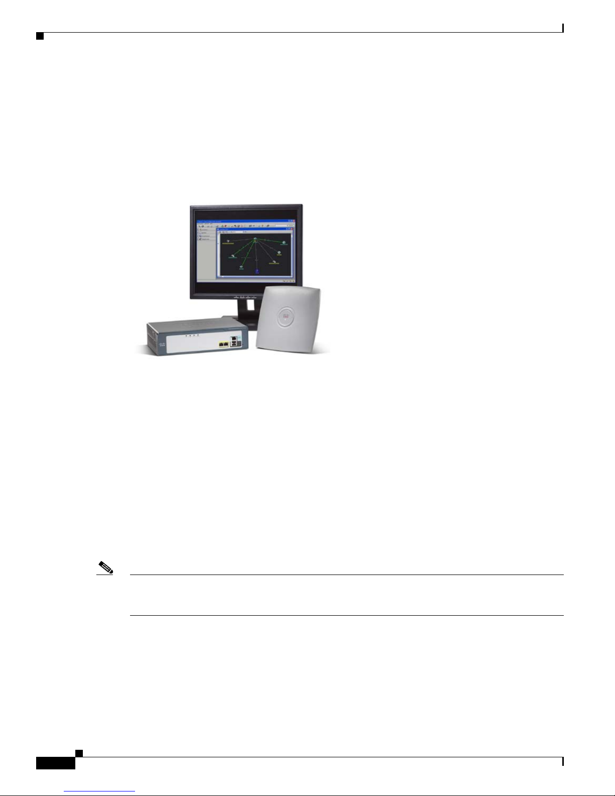
The Cisco Mobility Express Solution
The Cisco Mobility Express solution comprises access points, mobility controllers, and a configuration
assistant that is tailored to the needs of businesses with fewer than 250 employees.
Figure 1-1 shows the Cisco Mobility Express Solution elements.
Figure 1-1 Cisco Mobility Express Solution Elements
Chapter 1 Overview
The Cisco 521 Wireless Express Access Point
The Cisco 521 Wireless Express Access Point is a single-band 802.11g access point that features
business-class management, security, and scalability. It supports high-performance wireless connectivity
in carpeted offices and similar environments. They can be deployed in two modes—standalone or
controller-based:
• Standalone (referred to as an AP521 access point)—Up to three AP521 access points can be
deployed to provide wireless connectivity between the devices and the rest of the network. In this
configuration, the access points are managed individually through the CCA.
• Controller-based (referred to as a lightweight or LAP521 access point)—Up to 12 LAP521 access
points (six per wireless LAN controller) can be deployed and become multifunctional. In addition
to offering connectivity, the access points allow the controller to monitor all wireless activities
through them. In this configuration, they are managed by the controller through the CCA.
Note Cisco 500 series access points can associate only with Cisco 500 series controllers. Because the needs
of Cisco Mobility Express customers are different than those of enterprise customers, these access points
do not operate with other controllers.
For more information about Cisco 521 Wireless Express Access Points, refer to the Quick Start Guide:
Cisco 521 Wireless Express Access Point.
Cisco 500 Series Wireless Express Mobility Controller Configuration Guide
1-2
OL-15283-01
Page 19

Chapter 1 Overview
The Cisco 526 Wireless Express Mobility Controller
The WLC526 controller is easy to deploy, use, and maintain. The CCA interface and the automated
Radio Resources Management (RRM) tool configure the access points automatically to avoid
interference or coverage gaps while maximizing the bandwidth available. If the controller detects an
access point failure or a point of interference, it immediately takes action tuning the radio power or
frequency of surrounding access points to compensate and maintain business continuity without
affecting the devices connected to the wireless network.
A single WLC526 controller supports up to six LAP521 access points. A second WLC526 controller can
be added to the network to support redundancy or to increase capacity to 12 access points, or both.
Cisco Configuration Assistant
The CCA is a PC-based user interface created specifically for small-to-medium businesses with limited
networking resources and IT expertise. CCA manages the entire Smart Business Communications
System portfolio, including Cisco Mobility Express devices (see previous section) and these SBCS
devices:
• Cisco UC500 series appliances (UC500)—The UC500 includes voice and messaging features,
Public Switched Telephone Networks and Internet connectivity, integrated network security, and an
optional integrated WLAN access point to provide basic WLAN coverage in a small office space.
System Overview
• Catalyst Express 500 Series Switches (CE520)—These fixed-configuration, Layer 2-managed
Ethernet switches include wire-speed Fast Ethernet and Gigabit Ethernet connectivity, integrated
security, QoS, and Power-over-Ethernet (PoE) features.
• Cisco Unified IP Phones—The full Cisco Unified IP Phone portfolio is supported, including the
Cisco Unified IP Communicator and wireless IP phones.
Remote Configuring and Monitoring Capability
Cisco Monitor Director and Cisco Monitor Director Agent provide monitoring and reporting tools that
give network integrators real-time access to their supported customer networks. CCA supports remote
configuration. For more information about Cisco Monitor Director and Agent, refer to the Quick Start
Guide for Cisco Monitor Director 1.1 (Cisco Smart Business Communications System Release).
OL-15283-01
Cisco 500 Series Wireless Express Mobility Controller Configuration Guide
1-3
Page 20

WLC526 Controller Overview
WLC526 Controller Overview
This section outlines the features and specifications of the WLC526 controller.
Features and Benefits
Table 1-1 lists the features and benefits of the WLC526 controller.
Table 1-1 Features and Benefits of the WLC526 controller
Features Benefits
Secure network access for guest users
Support for Cisco voice-over-WLAN optimization
Easy management tool
Support for Cisco Lightweight Access Point Protocol
(LWAPP)
Support for up to 6 access points per controller and
up to 2 controllers per network for a total of 12
access points
Multi-access-point Radio Resource Management
(RRM)
Secure authentication mechanism support
Wired/wireless network virtualization
Chapter 1 Overview
Secure guest access enables you to easily create and
manage a virtual guest network with a Web login
portal page for users such as customers, vendors, and
contractors. Visitors can have Internet access while
safely partitioned from the sensitive corporate LAN.
Voice-over-WLAN optimization is a package of
features that deliver quality of service, call admission
control, and fast, secure inter-access-point handoff to
improve the quality of a wireless voice infrastructure.
Within CCA are Smart Assist features that enable
plug-and-play functionality and optimize network
settings.
Uses Cisco LWAPP for communication between
Cisco 500 series access points and WLC526
controllers to simplify deployment and management,
and to automate functions required for seamless
wireless coverage.
The wireless network easily expands as business
requirements for additional wireless coverage and
mobility services increase.
RRM automatically optimizes radio coverage and
capacity while working around potential points of
interference. This real-time radio coordination
simplifies deploying multiple access points.
Supports a wide range of authentication mechanisms
to enable scalable security architectures and
minimizes security interoperability problems (see the
“Security/Authentication Standards” section on
page 1-5)
Supports the use of up to 8 SSID/VLANs so that one
physical WLAN infrastructure can be safely shared
by users, applications, or organizations with different
network and security requirements.
Cisco 500 Series Wireless Express Mobility Controller Configuration Guide
1-4
OL-15283-01
Page 21

Chapter 1 Overview
WLC526 Controller Specifications
Table 1-2 lists product specifications for the WLC526 controller.
Table 1-2 WLC526 Controller Specifications
Item Specification
Physical Interfaces
Wired/Switching/Routing protocols
Management Options
Security/Authentication Standards
RADIUS Authentication
Multiple Service Set Identifiers (SSIDs)
WLC526 Controller Overview
Two 10/100 Ethernet ports for uplink and management
•
• Two USB console ports (future expansion)
• One RJ-45 serial port for direct console access
IEEE 802.3 10BASE-T
•
• IEEE 802.3u 100BASE-TX
• IEEE 802.1Q VLAN tagging
CCA software (recommended primary interface)
•
• Controller web-browser interface
• Limited command-line interface for troubleshooting
using Telnet, SSH, or console port access
• None/Open • WEP/Open
• MAC Filtering • WPA/Open with EAP
• WPA/Network EAP • WPA-PSK/Network EAP
• WPA-PSK/Open with EAP • WPA2/AES CCMP
• Protected EAP • Cisco LEAP
• EAP- TLS • EAP Generic Token Card
• EAP-SIM
IEEE 802.1x RADIUS authentication (external RADIUS
•
server required)
• Eight SSIDs supported (each access point may support
multiple SSIDs)
OL-15283-01
Support for Cisco Secure Guest Access
through CCA
Support for Voice-over-WLAN
Optimization
Cisco 500 Series Wireless Express Mobility Controller Configuration Guide
• One SSID broadcast in SSID beacon
•
Guest SSID/VLAN
• Auto-expiring guest user accounts
• Custom guest login page
•
Quality of service
• Call admission control
• Fast inter-access point hand-off
• Other optimization features designed to improve the
quality of a wireless voice infrastructure
1-5
Page 22

Configuration Options
Configuration Options
Like many Cisco devices, the WLC526 controller can be configured and operated through more than one
interface. They are:
• Cisco Configuration Assistant (CCA)
• Controller web-browser interface (GUI)
• Command-line interface (CLI)
This section explains use and limitations of each interface.
Using the Cisco Configuration Assistant
The CCA is your primary tool to install, set up, configure, and monitor all the Cisco Smart Business
Communications System devices. Many common tasks are automated, simplified, or guided to help you
to establish and administer a safe, optimized wireless network.
Chapter 1 Overview
Note There is no charge to download or use this software. For information about downloading and installing
CCA, refer to Getting Started with Cisco Configuration Assistant 1.5.
The following sections highlight some of the setup and configuration tools available in CCA.
Device Setup Wizard
The CCA Device Setup Wizard guides you through the steps for making devices ready to use and ready
for CCA to manage. For more information about using the Device Setup Wizard, see Chapter 2, “Adding
a WLC526 Controller and LAP521 Access Points.”
Note The CCA Device Setup Wizard supports WLC526 controllers running software versions 4.2 and above.
For controllers running earlier versions, see the
section on page 1-8.
Cisco Smart Assist
CCA includes Cisco Smart Assist features with plug-and-play functionality. Smart Assist features
reduce the time it takes to set up devices and applications and optimize your network settings. Cisco
Smart Assist features include:
• Default configurations to allow auto discovery of supported devices
“Using the Controller Web-Browser Interface (GUI)”
• Private branch exchange (PBX) configuration on the Cisco UC500 series appliance
• Firewall activation included in the default configuration
• Automatic assignment of phone extensions
• Password and VLAN synchronization for supported system devices
• Predefined configuration templates that automate SSID policy configuration, minimizing the
number of parameters required to complete configuration
Cisco 500 Series Wireless Express Mobility Controller Configuration Guide
1-6
OL-15283-01
Page 23

Chapter 1 Overview
• Easy WLAN monitoring through a single-screen snapshot view of all WLAN network elements and
statistics
• Extensive online help for configuring common client devices.
CCA Guide Mode and CCA Expert Mode
Most of the choices on the feature bar, toolbar, and popup menus open feature windows or guide steps.
Feature windows are compact—all your options are presented together, without explanatory words. To
see explanations, click Help. Guide steps, on the other hand, present one option at a time and explain
what to do for that option. When you use feature windows, you are in expert mode; when you use guide
steps, you are in guide mode.
CCA is in expert mode by default. The features that you see on the feature bar with an icon beside them
can also be shown in guide mode (see Figure 1-2). To access guide mode, choose Guide on the
Application menu before you select a task. To return to expert mode, choose Expert on the Application
menu, then select the task.
Figure 1-2 Guide Mode Signposts
Configuration Options
1 Examples of features that are available in
guide mode and expert mode
OL-15283-01
2 Examples of features that are available only in
expert mode
Cisco 500 Series Wireless Express Mobility Controller Configuration Guide
1-7
Page 24

Configuration Options
Smartport Support for Catalyst Express 500 Series Switches
CCA recognizes and supports Cisco Smartport technology, a collection of pretested,
Cisco-recommended baseline configuration templates for CE520 switches. The Smartports Advisor
detects connected Cisco Smart Business Communications System devices and suggests recommended
network configuration, QoS, security, and multicast settings.
CCA detects where you have not used Smartports to configure a device connection and alerts you from
the Event Notification window. You can configure the connection either manually or based on
suggestions provided by CCA. Open the Smartports window to either select a role to apply, or use
Smartports to suggest a role to apply.
Note The CCA Smartports option is accessible when there is one or more 520 series switch connected to the
network.
Using the Controller Web-Browser Interface (GUI)
The controller web-browser interface (referred to generically as the GUI) is part of the embedded
software of the WLC526 and has a different but overlapping set of features and capabilities from the
CCA. Use the controller GUI for the following tasks:
Chapter 1 Overview
• Controller setup—Use this interface when a WLC526 controller running software versions 4.0 or
4.1 powers on for the first time. The GUI Setup Wizard guides you through the necessary steps for
basic controller configuration. For information about this process, refer to the Quick Start Guide:
Cisco 526 Wireless Express Mobility Controller.
Note WLC526 controllers running software releases 4.2 and later can use the CCA Device Setup
Wizard.
• Advanced configuration tasks—IT professionals who have experience with Cisco GUIs can also
use the Wireless Express 500 series controller GUI to perform a number of advanced configuration
tasks that cannot be done in the current version of CCA. GUI-only tasks include:
–
Advanced monitor and client statistics
–
Advanced WLAN configuration options
–
Advanced QoS settings
–
Advanced WLAN layer 2 and 3 settings
–
Controller advanced interface settings
–
Controller advanced CDP settings
–
Controller advanced DHCP settings
–
Wireless advanced access point configuration settings
–
Wireless advanced access point QoS, timers, and regulatory settings
–
Wireless advanced RRM configuration
–
Security advanced configuration settings
–
Advanced MAC filtering
–
Advanced security for client management
Cisco 500 Series Wireless Express Mobility Controller Configuration Guide
1-8
OL-15283-01
Page 25

Chapter 1 Overview
–
Advanced client exclusion policies
–
Advanced security for access point management
–
Advanced SNMP configuration
–
Advanced controller management configuration
–
Guest Lobby Administrator configuration
–
Advanced controller troubleshooting configuration
–
Advanced log configurations
–
Advanced controller file management configuration options
For help with these and other advanced configuration tasks, refer to the GUI online help.
Using the Command-Line Interface
Use the controller command line interface (CLI) if you are experienced using Cisco CLI commands and
want to display system parameters or access debugging information (see Example 1-1).
Configuration Options
Example 1-1 CLI Command Output Example
(Cisco Controller) >show stats switch summary
Packets Received Without Error................... 443557435
Broadcast Packets Received....................... 73998045
Packets Received With Error...................... 0
Packets Transmitted Without Error................ 468934
Broadcast Packets Transmitted.................... 2341
Transmit Packet Errors........................... 0
Address Entries Currently In Use................. 2
VLAN Entries Currently In Use.................... 1
Time Since Counters Last Cleared................. 76 day 6 hr 38 min 23 sec
(Cisco Controller) >
Note The WLC526 controller is simple to install and operate; therefore, the controller CLI consists of a
limited number of primarily show and debug commands.
OL-15283-01
Cisco 500 Series Wireless Express Mobility Controller Configuration Guide
1-9
Page 26

Configuration Options
Chapter 1 Overview
Cisco 500 Series Wireless Express Mobility Controller Configuration Guide
1-10
OL-15283-01
Page 27

Adding a WLC526 Controller and LAP521
Access Points
This chapter provides instructions on adding a WLC526 controller and controller-based LAP521 access
points to your network using CCA. These sections are provided in this chapter:
• Obtaining and Installing CCA, page 2-1
• Starting CCA, page 2-1
• Adding a New Controller, page 2-2
• Verifying and Configuring Your Ethernet Adapter, page 2-9
• Adding LAP521 Access Points, page 2-11
Obtaining and Installing CCA
CHA PTER
2
If you have not already installed CCA, go to the following Cisco.com URL, click Download Software
and follow the instructions:
http://www.cisco.com/en/US/products/ps7287/index.html
For CCA installation instructions, refer to Getting Started with Cisco Configuration Assistant 1.5:
http://www.cisco.com/en/US/products/ps7287/prod_installation_guides_list.html
Starting CCA
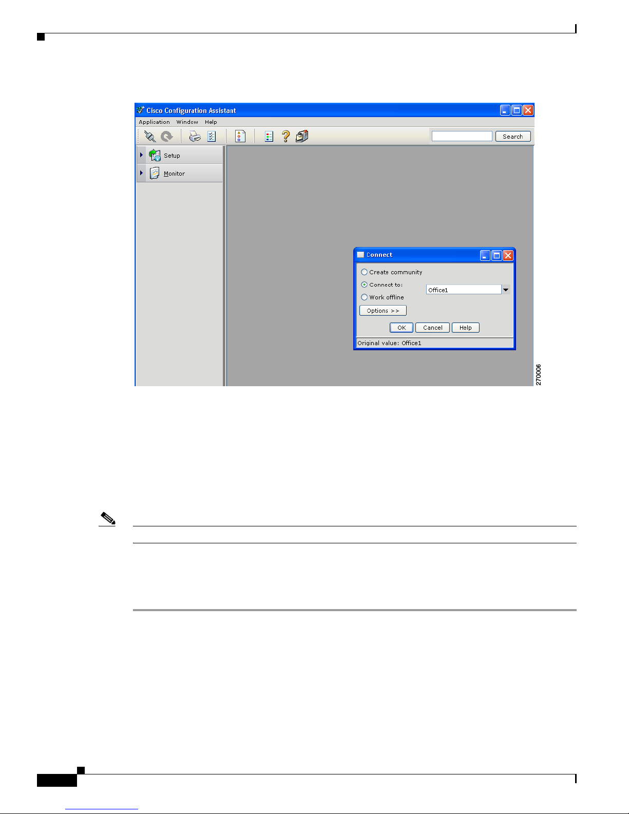
Double-click the CCA icon on your desktop to start the application and the CCA window appears (see
Figure 2-1).
OL-15283-01
Cisco 500 Series Wireless Express Mobility Controller Configuration Guide
2-1
Page 28
Adding a New Controller
Chapter 2 Adding a WLC526 Controller and LAP521 Access Points
Figure 2-1 CCA Window
For additional information about the CCA interface, windows, icons, or menus, refer to Getting Started
with Cisco Configuration Assistant 1.5.
Adding a New Controller
You can use CCA to add and configure your controller. CCA provides a device setup wizard to simplify
the configuration process.
Note The CCA device setup wizard only supports WLC526 Release 4.2 controllers.
The Ethernet adapter on your PC must be configured to automatically receive an IP address from a DHCP
server (see the “Verifying and Configuring Your Ethernet Adapter” section on page 2-9).
Follow these instructions to use the device setup wizard to configure a new controller:
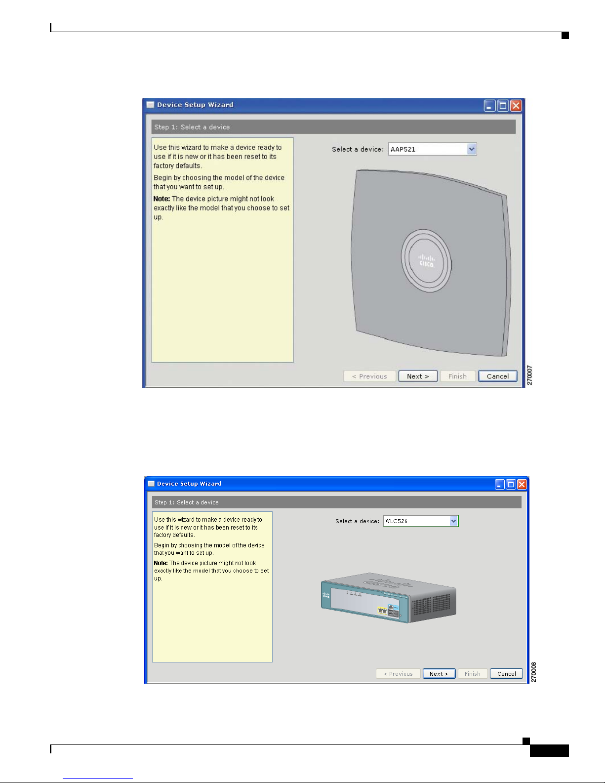
Step 1 To start the wizard, click Setup > Device Setup Wizard. The Step 1: Select a Device window appears
(see
Figure 2-2).
Cisco 500 Series Wireless Express Mobility Controller Configuration Guide
2-2
OL-15283-01
Page 29
Chapter 2 Adding a WLC526 Controller and LAP521 Access Points
Figure 2-2 Step 1: Select a Device Window
Adding a New Controller
Perform these operations:
a. In the Select a device field, click the drop down arrow and choose WLC526. Figure 2-3 appears
showing the controller.
Figure 2-3 Step 1 with WLC526 Selected
b. Click Next and the Step 2: Prepare a device window appears (see Figure 2-4
OL-15283-01
Cisco 500 Series Wireless Express Mobility Controller Configuration Guide
2-3
Page 30

Adding a New Controller
Chapter 2 Adding a WLC526 Controller and LAP521 Access Points
Figure 2-4 Step 2: Prepare a Device Window
Step 2 Verify that an Ethernet cable is not connected to any of the controller ports and click Next. The Step 3:
Power up a device window appears (see
Figure 2-5).
Figure 2-5 Step 3: Power Up Device Widow
Step 3 Perform these operations:
a. Connect an AC power cable to the controller.
b. When the power LED turns green, click Next. The Step 4: Connect your device to your PC/Laptop
window appears (see Figure 2-6).
Cisco 500 Series Wireless Express Mobility Controller Configuration Guide
2-4
OL-15283-01
Page 31

Chapter 2 Adding a WLC526 Controller and LAP521 Access Points
Figure 2-6 Step 4: Connect Device to Your PC/Laptop Window
Adding a New Controller
Step 4 Connect a Category 5 Ethernet cable from your PC and to Port 1 on the controller.
Step 5 When the wizard verifies successful connection, the Step 5: Verify Connection with Device window
displays a successful connection message (see
Figure 2-7).
Figure 2-7 Step 5: Verify Connection with Device Window
Step 6 Click Next and the Step 6 Enter Hostname and User Authentication Information window appears
(see
Figure 2-8).
OL-15283-01
Cisco 500 Series Wireless Express Mobility Controller Configuration Guide
2-5
Page 32

Adding a New Controller
Chapter 2 Adding a WLC526 Controller and LAP521 Access Points
Figure 2-8 Step 6: Enter Hostname and User Authentication Information Window
Step 7 Perform these operations:
a. Enter a name for the controller (up to 31 ASCII characters) in the Hostname field.
Note The user name cannot contain these characters: space + # % / \ ? ; ' < > { } | ^ ~ [ ] ` " !
b. Enter the administrator password (up to 24 ASCII characters) into the Password field.
Note The password cannot contain these characaters: space + ? / \ < > # % { } | ^ ~ [ ] ` "
space + ? / \ < > # % { } | ^ ~ [ ] ` "
c. Repeat the administrator password in the Confirm password field.
d. Click Next and the Enter Device Setup Parameters window appears (see Figure 2-9).
Cisco 500 Series Wireless Express Mobility Controller Configuration Guide
2-6
OL-15283-01
Page 33

Chapter 2 Adding a WLC526 Controller and LAP521 Access Points
Figure 2-9 Step 7 Enter Device Setup Parameters Window
Adding a New Controller
Step 8 Perform these operations:
a. Accept the default setting to synchronize the controller time with your PC, or uncheck the
Synchronize with PC box.
b. If you unchecked the Synchronize with PC checkbox, configure the month, date, year, hour and
minute by clicking the appropriate drop-down arrows and choosing the desired settings.
c. Accept the default US country code or click the drop-down arrow and choose the desired country
code setting.
d. Click Next and the Step 8 Management and AP Manager Interface Information window appears
(see Figure 2-10).
Figure 2-10 Step 8: Management and AP Manager Interface Information Window
OL-15283-01
Cisco 500 Series Wireless Express Mobility Controller Configuration Guide
2-7
Page 34

Adding a New Controller
Step 9 For the management interface, perform these operations:
Chapter 2 Adding a WLC526 Controller and LAP521 Access Points
a. Enter the IP address of the management interface.
b. Accept the default subnet mask or enter a new subnet mask in the Subnet Mask field.
c. Enter the IP address of the default gateway (or router) in the Default Gateway field.
Note The VLAN identifier is set to 0 for an untagged VLAN. This setting cannot be changed with
the CCA. This setting must be the same on the switch.
d. Accept the default controller port 1 setting or click the drop-down arrow to choose port 2. These
ports are located on the controller front panel and are used to connect the controller to the network.
e. Enter the IP address of the DHCP server in the DHCP Server IP Address field.
Note The default for the Transport Mode is Layer 3 and cannot be changed with the CCA.
f. For the AP Manager interface, enter the IP address for the AP Manager in the IP Address field.
g. Click Next and the Step 9 Summary window appears (see Figure 2-11).
Figure 2-11 Step 9 Summary Window
Step 10 Carefully review the summary settings and perform one of these operations:
a. If the summary is incorrect or you desire to make changes, click Previous and the previous window
appears.
b. If the summary is correct, click Finish and the wizard begins to transfer the configuration
information to the controller (a progress bar appears). When the transfer is complete, the wizard
indicates the finish status on the window (see Figure 2-12).
Cisco 500 Series Wireless Express Mobility Controller Configuration Guide
2-8
OL-15283-01
Page 35

Chapter 2 Adding a WLC526 Controller and LAP521 Access Points
Figure 2-12 Step 9 Summary Window Finish Status
Verifying and Configuring Your Ethernet Adapter
Step 11 Click Close to exit the wizard.
Step 12 Remove your PC’s Ethernet cable from the controller.
Note Prior to using your PC and CCA to monitor your network, you need to reconfigure your PC
Ethernet adapter to a static IP address within the subnet of your network.
Step 13 Mount your access point in the desired location. For mounting information refer to the Quick Start Guide:
Cisco 526 Wireless Express Mobility Controller.
Step 14 Connect a Category 5 Ethernet cable from the controller management interface port (1 or 2 as configured
in
Step 9, above) to your switch.
Your controller is now configured and ready to accept access point connections.
Verifying and Configuring Your Ethernet Adapter
To verify that your Ethernet adapter is configured to receive an IP address from a DHCP server on a
Windows-based PC, follow these instructions:
Step 1 Click Start > Control Panel > Network Connections.
Step 2 Right-click on your Ethernet adapter and choose Properties.
Step 3 Scroll down the list of items and click Internet Protocol (TCP/IP).
Step 4 Click Properties and the Internet Protocol (TCP/IP) Properties screen appears.
Step 5 Ensure that Obtain an IP address automatically is checked.
Step 6 Click OK.
OL-15283-01
Cisco 500 Series Wireless Express Mobility Controller Configuration Guide
2-9
Page 36

Chapter 2 Adding a WLC526 Controller and LAP521 Access Points
Verifying and Configuring Your Ethernet Adapter
Step 7 Click OK on your Ethernet adapter properties screen.
Configuring your Ethernet Adapter to a Static IP Address
To configure your Ethernet adapter to a static IP address on a Windows-based PC, follow these
instructions:
Step 1 Click Start > Control Panel > Network Connections.
Step 2 Right-click on your Ethernet adapter and choose Properties.
Step 3 Scroll down the list of items and click Internet Protocol (TCP/IP).
Step 4 Click Properties and the Internet Protocol (TCP/IP) Properties screen appears.
Step 5 Check Use the following IP address.
Step 6 Enter the IP address, the subnet mask, and the default gateway IP address in the corresponding fields.
Step 7 Click OK.
Step 8 Click OK on your Ethernet adapter properties screen.
Verifying the IP Address of your Ethernet Adapter
The IP address of your Ethernet adapter must be configured within the same subnet as your system
components for use with CCA. To verify the IP address of your Ethernet adapter on a Windows-based
PC, follow these instructions:
Step 1 Click Start > Run and the Run pop-up window appears.
Step 2 Type cmd in the Open field and click OK. The cmd.exe pop-up window appears.
Step 3 In the pop-up window, type ipconfig and press Enter (see Figure 2-13).
Figure 2-13 IPCONFIG Results Window
Cisco 500 Series Wireless Express Mobility Controller Configuration Guide
2-10
OL-15283-01
Page 37

Chapter 2 Adding a WLC526 Controller and LAP521 Access Points
Step 4 After verifying the IP address of your Ethernet adapter, close the window by clicking the Red X box.
Adding LAP521 Access Points
Each WLC526 controller supports up to six controller-based LAP521 access points. For additional
information on mounting the access points, refer to the Quick Start Guide: Cisco 521 Wireless Express
Access Point at this Cisco.com URL:
http://www.cisco.com/en/US/docs/wireless/access_point/521/quick/guide/a521qsg.html
You must connect your LAP521 access points to a switch to enable communications with a controller.
Note The WLC526 controller supports only controller-based LAP521 access points. It does not support Cisco
Aironet lightweight access points, such as the 1000, 1130, 1200, 1240, 1250, 1300, 1500, or 1520 series
access points.
Adding LAP521 Access Points
Note The switch ports to which you connect your access points must be configured as access point smart
ports. You can use CCA or the switch web-browser interface to configure the switch ports.
The access points can be powered by PoE from your switch, by a power injector, or by a power module.
On power up, the access points begin a discovery process that automatically connects them with your
controller. The discovery process is indicated by the Status LED indicator on the access point blinking
green, red, and amber. When the access point associates with the controller, the Status LED changes to
light green. For more information about the LED color codes, refer to the Quick Start Guide: Cisco 521
Wireless Express Access Point.
When the LAP521 associates to the WLC526, the controller automatically downloads the latest
operating system and configures the access point.
OL-15283-01
Cisco 500 Series Wireless Express Mobility Controller Configuration Guide
2-11
Page 38

Adding LAP521 Access Points
Chapter 2 Adding a WLC526 Controller and LAP521 Access Points
Cisco 500 Series Wireless Express Mobility Controller Configuration Guide
2-12
OL-15283-01
Page 39

Creating and Connecting to a Community
This chapter describes how to create a community of devices and describes how to connect to a
community using the CCA. This chapter contains these sections:
• Community Overview, page 3-1
• Creating a Community of Devices Using the Connect Window, page 3-2
• Connecting To a Community, page 3-6
Community Overview
This section provides only a brief overview of communities. For additional information on CCA and
communities refer to the Getting Started with Cisco Configuration Assistant document available on
Cisco.com at this URL:
http://www.cisco.com/en/US/products/ps7287/prod_installation_guides_list.html
CHA PTER
3
CCA manages device groups called communities. In a community, every device must have an IP address.
CCA communicates directly with all members of the community, so an HTTPS link is possible with
every member.
Characteristics of a Community
In addition to offering the security of HTTPS links, a community has these characteristics:
• It can contain up to 25 SBCS devices, including the UC500, CE520, WLC526 controllers, and
stand-alone AP521 access points. Specific limitations include:
–
Five routers
–
Three AP521 autonomous wireless access points
–
Two wireless controllers (which can control up to an additional 12 AP521 access points
–
As many Cisco IP phones as there are available switch ports in the network
• Because every member has an IP address, if you lose communication with a member, you can still
communicate with other members.
• A basic set of networking tasks is supported for community members, including routers and access
points. The tasks are
–
Managing user access
OL-15283-01
Cisco 500 Series Wireless Express Mobility Controller Configuration Guide
3-1
Page 40

Creating a Community of Devices Using the Connect Window
–
Upgrading software
–
Saving a running configuration
–
Backing up and restoring a configuration
–
Managing the system time
–
Getting system message notifications
–
Changing the HTTP port number
–
Getting an inventory report
Creating a Community
You can create a community in either of these ways:
• When you launch CCA, you can use the Connect window that appears.
• Choose Application > Communities from the menu bar and use the Communities window that
appears.
• Choose Application > Connect and use the Connect window that appears.
• Click the Connect icon on the tool bar and use the Connect window that appears.
Chapter 3 Creating and Connecting to a Community
Community Limits
Table 3-1 lists the limits on the number of specific device types that can be supported in a community.
Table 3-1 Limits on the Number of Specific Device Types in a Community
Device Type Limit
Catalyst Express 500 Series Switches 15
Cisco UC500 series appliance 5
Wireless Express 500 series controllers 2
Autonomous AP521 access points 3
IP phones do not count toward the 25-device community limit. You can connect as many IP phones as
there are switch ports in the community’s UC500 appliances and CE500 switches.
If you exceed the device limits, you cannot manage the community until you remove enough devices to
comply with the limits.
There is no limit to the number of communities that CCA can manage.
Creating a Community of Devices Using the Connect Window
When you launch CCA, two windows open: the CCA window, which contains the user interface, and the
Connect window.
Cisco 500 Series Wireless Express Mobility Controller Configuration Guide
3-2
OL-15283-01
Page 41

Chapter 3 Creating and Connecting to a Community
CCA starts in a disconnected mode, it is not connected to a community or a standalone device. In this
mode, you see the menu bar in the CCA window and only the Setup and Monitor options of the feature
bar. The feature bar is populated with device features only when CCA is connected to a community.
The Connect window gives you these choices:
• Creating a new community. You first create the community and then connect to it.
• Connecting to an existing community or to a standalone device.
• Working offline. When you are offline, only the Voice feature is available on the feature bar. You
can specify options for voice communication, save them, and retrieve them in a later session, when
you do connect to a community or a standalone device.
To use the Connect window to create a new community of devices, follow these instructions:
Step 1 Check Create community in the Connect window (see Figure 3-1).
Figure 3-1 Connect Window
Creating a Community of Devices Using the Connect Window
Step 2 Click OK and the Create Community window appears (see Figure 3-2).
OL-15283-01
Cisco 500 Series Wireless Express Mobility Controller Configuration Guide
3-3
Page 42

Creating a Community of Devices Using the Connect Window
Figure 3-2 Create Community Window
Chapter 3 Creating and Connecting to a Community
3-4
Step 3 Enter the community name in the Name field (up to 64 characters, A-Z, a-z, 0-9, hyphen, and
underscore).
Step 4 (Optional) Enter your company name, your organization, or any other identifying text in the Company
Name field. The text is used as the default SSID (service set identifier) for your network.
Step 5 CCA uses the information from the Discovery option to discover devices and their neighbors using the
Cisco Discovery Protocol (CDP). The discovered devices and their neighbors are added to your
community. Choose a discover option by clicking the drop-down arrow in the Discover field and enter
the requested information as listed below:
–
A single device by IP address—Enter the IP address of the device you want CCA to discover.
–
Devices using a seed IP address—(default) Enter the IP address of a device with neighbors that
you want CCA to discover.
–
Devices on a subnet—Enter the IP address and a subnet mask.
–
Devices in an IP address range—Enter the start and end IP addresses of the range.
Step 6 Click Start. CCA begins the discovery process and displays a progress bar. When devices are
discovered, CCA includes the discovered devices in the Device table.
Step 7 If a pop-up window appears that indicates the expected amount of time for the discovery process, click
Ye s or No to continue.
Cisco 500 Series Wireless Express Mobility Controller Configuration Guide
OL-15283-01
Page 43

Chapter 3 Creating and Connecting to a Community
Step 8 If a Security Certificate Alert pop-up window appears (see Figure 3-3) to indicate that a certificate site
cannot be identified as a trusted site, you might want to examine the certificate by clicking View
Certificate. After examining the certificate, click Yes , No, or Always.
Figure 3-3 Security Certificate Alert Pop-Up Window
Creating a Community of Devices Using the Connect Window
Step 9 If an Authentication: Device pop-up windows appears (see Figure 3-4), enter the administrative
username and password for the indicated device.
Note For the WLC526 controller and the CE500 switch, the default username and password are both
admin.
Figure 3-4 Authentication: Device Pop-Up Window
When the discovery process complete, the discovered devices are listed in the Devices table
(see Figure 3-5).
OL-15283-01
Cisco 500 Series Wireless Express Mobility Controller Configuration Guide
3-5
Page 44

Connecting To a Community
Figure 3-5 Discovered Community Devices
Chapter 3 Creating and Connecting to a Community
Step 10 Click Ok.
Connecting To a Community
When you connect to a community, you can use CCA to communicate with and manage all of the
members. To connect to a community using the Connect window, follow these instructions:
Step 1 Check Connect to in the Connect window (see Figure 3-1).
Step 2 Click the drop-down arrow and choose from the list of configured communities (see Figure 3-6).
Cisco 500 Series Wireless Express Mobility Controller Configuration Guide
3-6
OL-15283-01
Page 45

Chapter 3 Creating and Connecting to a Community
Figure 3-6 Community Drop-Down List
Step 3 Click OK. CCA displays a discovery progress bar on the lower left side of the screen. When CCA
completes the discovery process, the Topology View window appears (see
Figure 3-7 Topology View Window
Connecting To a Community
Figure 3-7).
The topology shows the devices discovered, their connections, the connection ports, and other
information for the community that you specified. CCA provides topology options that specify the
information displayed for a device. To change the information displayed, right click on the information
and choose Top o log y O pti o n s.
OL-15283-01
Cisco 500 Series Wireless Express Mobility Controller Configuration Guide
3-7
Page 46

Connecting To a Community
Note After CCA has connected to a community, the Feature bar expands to cover additional device feature
options.
Chapter 3 Creating and Connecting to a Community
Cisco 500 Series Wireless Express Mobility Controller Configuration Guide
3-8
OL-15283-01
Page 47

Creating and Modifying WLANs and VLANs
This chapter describes how to use CCA to create and modify wireless LANs (WLANs) and virtual LANs
(VLANs). The chapter contains these sections:
• Creating a New WLAN, page 4-1
• Modify a WLAN, page 4-7
• Adding a VLAN, page 4-10
• Modifying a VLAN, page 4-14
Creating a New WLAN
This section describes how to use CCA to create a new WLAN. Follow these steps to create a new
WLAN:
CHA PTER
4
OL-15283-01
Cisco 500 Series Wireless Express Mobility Controller Configuration Guide
4-1
Page 48

Creating a New WLAN
Step 1 Click Configure > Wireless > WLANs (SSID) and the WLANs (SSID) window appears (see
Chapter 4 Creating and Modifying WLANs and VLANs
Figure 4-1).
Figure 4-1 WLAN (SSIDs) Window
4-2
Step 2 Click the Hostname drop-down arrow and choose the controller that you want to configure.
If you fail to configure a RADIUS server, a WLANs (SSIDs) pop-up window appears to indicate that
you should create a new RADIUS server (see Figure 4-2).
Figure 4-2 RADIUS Server Required display
Step 3 Click Configure and the Configure RADIUS Servers window appears (see Figure 4-3).
Cisco 500 Series Wireless Express Mobility Controller Configuration Guide
OL-15283-01
Page 49

Chapter 4 Creating and Modifying WLANs and VLANs
Figure 4-3 Configure RADIUS Servers Window
Creating a New WLAN
Step 4 Click Create and the Create RADIUS Server window appears (see Figure 4-4).
Figure 4-4 Create RADIUS Server Configuration Window
Step 5 Perform these operations:
a. Enter the RADIUS server IP address in the IP Address field.
b. Enter the RADIUS server secret key in ASCII in the Secret Key (ASCII) field.
c. Reenter the secret key in the Confirm Secret Key field.
d. Click the Server Priority drop-down arrow and choose the priority (1 or 2). The primary server is
used first and is specified by a priority of 1. The secondary server is used when the primary server
cannot be reached and is specified by a priority of 2.
e. Click the Admin Status drop-down arrow and choose Enabled (default) or Disabled.
f. Click OK and the RADIUS Server entry is listed in the RADIUS server table.
Step 6 Click Apply and the RADIUS server configuration information is saved.
OL-15283-01
Cisco 500 Series Wireless Express Mobility Controller Configuration Guide
4-3
Page 50

Creating a New WLAN
Step 7 To configure a secondary RADIUS server, repeat Steps 5 and 6.
Step 8 When done entering RADIUS servers information, click OK and a pop-up message (see Figure 4-5)
Step 9 Click Ye s on the pop-up message and the WLANs (SSIDs) window appear again (see Figure 4-1).
Step 10 Click Create to create a WLAN and Figure 4-6 appears.
Chapter 4 Creating and Modifying WLANs and VLANs
appears asking if you want to create SSIDs using the RADIUS server.
Figure 4-5 Configure RADIUS Server Pop-Up Message
Figure 4-6 Create WLAN Window
Step 11 Choose the WLAN type by checking Data, Voic e, or Guest.
Note For voice or data WLAN types, the VLAN ID is automatically selected.
Step 12 Enter an SSID in the SSID field (up to 32 alphanumeric characters without spaces).
Note For the guest WLAN type, the SSID can contain a space character but not a leading or trailing
space character.
Step 13 Uncheck Broadcast in Beacon if you don’t want the SSID included in the beacon packets.
Cisco 500 Series Wireless Express Mobility Controller Configuration Guide
4-4
OL-15283-01
Page 51

Chapter 4 Creating and Modifying WLANs and VLANs
Step 14 Accept the VLAN or click the drop-down arrow to choose another configured VLAN.
Step 15 To add a VLAN, click Add VLAN (for instructions on adding a VLAN refer to the “Adding a VLAN”
section on page 4-10).
Step 16 Check Web Authentication if you want to create a guest or employee user. This option is enabled by
default for Guest WLANs.
Step 17 Click the Security Type drop-down arrow and choose one of these security options:
• No Security—This is the least secure option. Select it only for an SSID that is used in a public place
(guest SSID), and associate it with a VLAN that restricts access to your network. There is no
encryption, and the authentication type is open authentication.
• WEP—This security setting requires that the access point and the client device (a device that
connects to the wireless device such as a laptop or a PC) share the same WEP key to keep the
communication private.
• EAP—This security setting enables IEEE 802.1X authentication and requires you to select the IP
address of a RADIUS server. The encryption type is WEP, and the authentication type is IEEE
802.1x.
• WPA—This security setting is more secure than the EAP setting. It enables WPA authentication and
requires you to select the IP address of a RADIUS server. Client devices that associate with the
access point by using this SSID must be WPA-capable.
Creating a New WLAN
• WPA-PSK—Select this security setting when you want to use the WPA encryption and you do not
have access to a RADIUS server. It requires that the access point and the client device share the same
WPA-PSK. The key can be from 8 to 63 characters long.
• WPA2—This security setting is more secure than the WPA setting. It enables WPA2 authentication
and requires you to select the IP address of a RADIUS server. Client devices that associate with the
access point by using this SSID must be WPA2-capable.
• WPA2-PSK—Select this security setting when you want to use WPA2 encryption and you do not
have access to a RADIUS server. It requires that the access point and the client device share the same
WPA2-PSK. The key can be from 8 to 63 characters long. The authentication type is WPA2-PSK.
• MAC—Select this security setting when you want to authenticate client devices by using MAC
address-based authentication. There is no encryption, and the authentication type is IEEE 802.1x.
Step 18 If you choose WEP security, perform these steps:
a. In the Authentication field, click the drop-down arrow and choose Open or shared key.
b. In the Key Format field, click the drop-down arrow and choose Hex or ASCII.
c. Click the Hex Key field drop-down arrow and choose 1, 2, 3, 4.
d. Click the key size drop-down arrow and choose one of these options:
–
104 bits—Requires 13 ASCII characters or 26 Hex digits.
–
40 bits—Requires 5 ASCII characters or 20 Hex digits.
e. If you selected a hex key format, choose one of these options:
–
Enter the encryption key (see key size above).
–
Enter a passphrase (8 to 63 characters) and click Generate for the encryption key to be
automatically created (see Figure 4-7).
OL-15283-01
Cisco 500 Series Wireless Express Mobility Controller Configuration Guide
4-5
Page 52

Creating a New WLAN
Chapter 4 Creating and Modifying WLANs and VLANs
Figure 4-7 Passphrase and Auto-Generated Hex Key
Step 19 If you choose WPA security, perform these steps:
a. Click the Encryption drop-down arrow and choose aes or tkip.
b. Click the Authentication drop-down arrow and choose one of these authentication options:
–
802.1x (default)
–
Fast roaming (CCKM)
–
802.1x, fast roaming (CCKM)
Step 20 If you choose WPA-PSK, WPA2, or WPA2-PSK security, perform these steps:
a. Click the Encryption drop-down arrow and choose AES or TKIP.
Note The authentication is WPA-PSK, WPA2-PSK, or WPA2-PSK corresponding to the security type.
b. Enter the WPA pre-shared key (8 to 63 characters long).
Step 21 If you selected a voice WLAN type, choose one of these voice CAC types:
• Wireless MultiMedia Policy—(Default) requires client devices to use WMM.
• 7920 CAC (AP and Client)—Supports Cisco 7920 IP telephones on your network.
Step 22 Click OK and the specified WLAN information is visible in the WLAN Names list (see Figure 4-8).
Cisco 500 Series Wireless Express Mobility Controller Configuration Guide
4-6
OL-15283-01
Page 53

Chapter 4 Creating and Modifying WLANs and VLANs
Figure 4-8 WLAN List
Modify a WLAN
Modify a WLAN
To modify a WLAN, follow these steps:
Step 1 Click Configure > Wireless > WLANs and the WLANs window appears (see Figure 4-12):
OL-15283-01
Cisco 500 Series Wireless Express Mobility Controller Configuration Guide
4-7
Page 54

Modify a WLAN
Chapter 4 Creating and Modifying WLANs and VLANs
Figure 4-9 WLAN Window with Defined WLANs
4-8
Step 2 Click Modify and Figure 4-10 appears.
Cisco 500 Series Wireless Express Mobility Controller Configuration Guide
OL-15283-01
Page 55

Chapter 4 Creating and Modifying WLANs and VLANs
Figure 4-10 Modify WLAN Window
Modify a WLAN
Step 3 Change the WLAN information as needed and then click OK. Figure 4-11 appears with the changed
information.
OL-15283-01
Cisco 500 Series Wireless Express Mobility Controller Configuration Guide
4-9
Page 56

Adding a VLAN
Chapter 4 Creating and Modifying WLANs and VLANs
Figure 4-11 WLAN Window with Modified Information
Step 4 Click OK.
Adding a VLAN
To add a new VLAN, follow these steps:
Step 1 Click Configure > Wireless > VLANs and the VLANs window appears (see Figure 4-12):
Cisco 500 Series Wireless Express Mobility Controller Configuration Guide
4-10
OL-15283-01
Page 57

Chapter 4 Creating and Modifying WLANs and VLANs
Figure 4-12 VLANs Window with Existing VLANs
Adding a VLAN
Step 2 Click Create and the Create VLANs window appears (see Figure 4-13).
Figure 4-13 Create VLAN Window
OL-15283-01
Cisco 500 Series Wireless Express Mobility Controller Configuration Guide
4-11
Page 58

Adding a VLAN
Step 3 Perform these steps:
Step 4 When the pop-up message appears that indicates you should configure a DHCP server with IP addresses
Chapter 4 Creating and Modifying WLANs and VLANs
a. Enter a VLAN ID value (2 to 1000) into the VLAN ID field.
b. Accept the auto generated VLAN name or enter a unique name in the VLAN Name field.
c. Accept the displayed controller Port number or click the drop-down arrow and choose 2.
d. Enter an IP address for the VLAN in the IP Address field.
e. Accept the displayed subnet mask or enter a new subnet mask value.
f. Enter the IP address for the Gateway (or router) in the Gateway IP Address field.
g. Enter the IP address for the DHCP server in the DHCP Server IP Address field.
h. When you reviewed your entries, click OK.
for the VLAN subnet (see
Figure 4-14 Info: Create VLAN Message Reminder
Figure 4-14), you should record the reminder and click OK.
The VLANs window (see Figure 4-15) appears and contains the added VLAN.
Cisco 500 Series Wireless Express Mobility Controller Configuration Guide
4-12
OL-15283-01
Page 59

Chapter 4 Creating and Modifying WLANs and VLANs
Figure 4-15 VLANs Window with the New VLAN
Adding a VLAN
Step 5 If you need to add more VLANS, click Apply and repeat Steps 2 through Step 4.
Step 6 When you have finished adding VLANs, click OK.
Step 7 If CCA detects an error or a conflict with a settings already configured in the switch, a pop-up message
appears indicating you should revise the field indicated with a red box. Make necessary corrections and
click OK.
Step 8 If a pop-up message appears (see Figure 4-16) that indicates the corresponding VLANs in all switches
will be updated, click OK.
Figure 4-16 VLANs Pop-Up Message
Step 9 When a pop-up message appears (see Figure 4-17) that asks if you want to create an SSID using the
VLAN data, click Yes o r No .
OL-15283-01
Cisco 500 Series Wireless Express Mobility Controller Configuration Guide
4-13
Page 60

Modifying a VLAN
Figure 4-17 Create SSID Prompt
Step 10 If you choose Yes to create an SSID, go to Step 10 in the Create WLAN section to enter the new SSID
information.
Modifying a VLAN
To modify an existing VLAN, follow these steps:
Chapter 4 Creating and Modifying WLANs and VLANs
Step 1 Click Configure > Wireless > VLANs and the VLANs window appears (see Figure 4-18):
Figure 4-18 VLANs Window with Existing VLANS
Step 2 Click the VLAN that you want to modify to highlight it (see Figure 4-18).
Step 3 Click Modify and the Modify VLAN window appears (see Figure 4-19).
Cisco 500 Series Wireless Express Mobility Controller Configuration Guide
4-14
OL-15283-01
Page 61

Chapter 4 Creating and Modifying WLANs and VLANs
Figure 4-19 Modify VLAN Window
Modifying a VLAN
Step 4 Use the left mouse button to highlight the data you want to modify, then enter the desired data.
Step 5 When you have finished modifying the data fields, click OK. Figure 4-20 appears and contains the
revised VLAN.
Figure 4-20 VLANs Window with Revised VLAN
OL-15283-01
Cisco 500 Series Wireless Express Mobility Controller Configuration Guide
4-15
Page 62

Modifying a VLAN
Step 6 If you need to revise additional VLANs, click Apply and repeat Step 2 through Step 5.
Step 7 When you have finished modifying the VLANs, click OK.
Chapter 4 Creating and Modifying WLANs and VLANs
Cisco 500 Series Wireless Express Mobility Controller Configuration Guide
4-16
OL-15283-01
Page 63

CHA PTER
Controller Software Upgrade
This chapter describes how to upgrade WLC526 controller software using CCA. This chapter contains
these sections:
• Obtaining the Controller Software Image, page 5-1
• Upgrading Controller Software, page 5-1
Obtaining the Controller Software Image
Prior to attempting a software upgrade, you must obtain the software image for your controllers and
autonomous access points. The latest software images are available for download from Cisco.com at this
URL:
http://www.cisco.com/en/US/products/ps7320/index.html
Click Software Download and follow the prompts to obtain the latest WLC526 controller software
image. Save the software images to your hard drive.
5
Upgrading Controller Software
CCA enables you to upgrade software on a single device or to simultaneously upgrade the software on
multiple devices. This section will describe how to upgrade your controller software using the feature
bar software upgrade option.
Follow these steps to upgrade your controller software:
Step 1 Click Maintenance > Software Upgrade and Figure 5-1 appears.
Cisco 500 Series Wireless Express Mobility Controller Configuration Guide
OL-15283-01
5-1
Page 64

Upgrading Controller Software
Figure 5-1 Controller Software Upgrade Window
Chapter 5 Controller Software Upgrade
Step 2 Highlight your switch and click Upgrade Settings. Figure 5-2 appears.
Figure 5-2 Upgrade Settings Window
Step 3 Click the drop-down arrow in the Mode field and choose Standard or Remote TFTP Server.
Step 4 If you selected Standard, enter the path/filename of the controller software image in the IOS Image field
or click Browse and navigate to the controller software image file on your hard drive.
Step 5 If you selected Remote TFTP Server, perform these steps:
a. Enter the filename of the controller software image in the IOS Image field.
b. Enter the TFTP server IP address in the corresponding field.
Note The controller software image file must be in your TFTP server download directory.
Step 6 Click OK and Figure 5-3 appears.
Cisco 500 Series Wireless Express Mobility Controller Configuration Guide
5-2
OL-15283-01
Page 65

Chapter 5 Controller Software Upgrade
Figure 5-3 Controller Upgrade Selected
Upgrading Controller Software
Step 7 Click Upgrade and Figure 5-4 appears.
Figure 5-4 Software Upgrade Pop Up Message
Step 8 Click one of these options:
• Yes—to continue with the software upgrade. Figure 5-5 appears.
• No—to specify upgrade options for another device. Go to Step 6 to enter additional upgrade
information.
Figure 5-5 Loading the Controller Image
The upgrade status field indicates CCA is uploading the software image to the controller.
You can click Status at any time to view status information (see Figure 5-2).
OL-15283-01
Cisco 500 Series Wireless Express Mobility Controller Configuration Guide
5-3
Page 66

Upgrading Controller Software
Figure 5-6 Software Upgrade Status Information
When the controller software upgrade is completed, a pop-up message (Figure 5-7) appears and
indicates the successful upgrade of the controller. The message indicates that the controller must be
reloaded to use the new software and asks if you want to reload the software.
Chapter 5 Controller Software Upgrade
Figure 5-7 Software Upgrade Pop-Up Message
Step 9 Click Ye s to reload the controller and Figure 5-8 appears indicating the controller is being reloaded.
Cisco 500 Series Wireless Express Mobility Controller Configuration Guide
5-4
OL-15283-01
Page 67

Chapter 5 Controller Software Upgrade
Figure 5-8 Reloading the Controller
Upgrading Controller Software
Step 10 If you click Status, Figure 5-9 appears and indicates the reload status.
Figure 5-9 Reload Status Information
When the reload completes, Figure 5-10 appears and indicates the upgrade status is successful.
OL-15283-01
Cisco 500 Series Wireless Express Mobility Controller Configuration Guide
5-5
Page 68

Upgrading Controller Software
Figure 5-10 Software Upgrade Complete
Step 11 After reviewing the information provided in the window, close the window by clicking the red X button
the top right of the window.
Chapter 5 Controller Software Upgrade
Cisco 500 Series Wireless Express Mobility Controller Configuration Guide
5-6
OL-15283-01
Page 69

CHA PTER
6
Restarting, Resetting, Backing Up, and Restoring
the Controller
This chapter describes how to restart the controller, reset the controller to factory defaults, backup the
controller configuration, and restore the controller configuration. The chapter contains these sections:
• Restarting the Controller Using CCA, page 6-1
• Resetting the Controller to Factory Default Values Using CCA, page 6-3
• Backing Up the Controller Configuration, page 6-4
• Restoring the Controller Configuration, page 6-8
• Manually Restarting the Controller Using the Reset Button, page 6-11
• Manually Resetting the Controller to Factory Defaults, page 6-12
Restarting the Controller Using CCA
Follow these instructions to restart the controller using CCA:
Step 1 Click Maintenance > Restart/Reset and Figure 6-1 appears.
OL-15283-01
Cisco 500 Series Wireless Express Mobility Controller Configuration Guide
6-1
Page 70

Restarting the Controller Using CCA
Figure 6-1 Restart and Reset Device Selections
Step 2 For your controller, check Restart. Figure 6-2 appears and shows the controller restart check box has
been checked.
Chapter 6 Restarting, Resetting, Backing Up, and Restoring the Controller
Figure 6-2 Restart Check Box
Step 3 If you need to restart another controller, click Apply and return to Step 2.
Step 4 Click OK and a pop-up message appears (see Figure 6-3). The message indicates the controller(s) will
reload in approximately 1 minute. The message also indicates that you might need to refresh the CCA
screen by clicking Application > Refresh after the controllers are restarted.
Cisco 500 Series Wireless Express Mobility Controller Configuration Guide
6-2
OL-15283-01
Page 71

Chapter 6 Restarting, Resetting, Backing Up, and Restoring the Controller
Figure 6-3 Reload Confirmation Pop-Up Message
Step 5 Click Ye s to begin the reset process.
When the controller reset completes, the window closes automatically.
Resetting the Controller to Factory Default Values Using CCA
Resetting the Controller to Factory Default Values Using CCA
To reset the controller to factory default values using the CCA, follow these instructions:
Step 1 Click Maintenance > Restart/Reset and Figure 6-4 appears.
Figure 6-4 Restart/Reset Window
Step 2 On the controller line, check Reset to Factory Defaults. Figure 6-5 appears and indicates the reset will
being in approximately 1 minute for the selected devices. The message indicates CCA will loose
connectivity with the controller after it has been reset to factory defaults. To reconfigure the controller,
go to the
OL-15283-01
“Adding a New Controller” section on page 2-2.
Cisco 500 Series Wireless Express Mobility Controller Configuration Guide
6-3
Page 72

Backing Up the Controller Configuration
Figure 6-5 Restart/Reset Message
Step 3 If you want to backup your current controller configuration, go to the “Backing Up the Controller
Configuration” section on page 6-4 for additional instructions.
Step 4 If you want to continue with the reset of the controller, click Ye s.
Chapter 6 Restarting, Resetting, Backing Up, and Restoring the Controller
When the reset process is complete, CCA returns to the main CCA screen displaying the Topology View.
If you click the Refresh icon, CCA refreshes the topology view and the previously configured controller
is shown not connected to the switch. CCA also detects the unconfigured controller with a default IP
address of 192.168.1.1 connected to the controller. To configure the controller, go to the “Adding a New
Controller” section on page 2-2.
Backing Up the Controller Configuration
You can backup the controller configuration during the process of resetting the controller to defaults or
from the Maintenance options. This section describes both methods of backing up the controller
configuration.
Note On CCA Release 1.5, the CCA restore function only supports backup files created using CCA
Release
binary configuration files, but CCA Release 1.5 and higher supports XML configuration files.
To back up a controller configuration, follow these steps:
Step 1 Click Launch Configuration Archive from the Restart/Reset pop-up message window or click
Maintenance > Configuration Archive.
1.5. You cannot use backup files created with CCA Release 1.1. CCA Release 1.1 supports
Figure 6-6 appears.
Cisco 500 Series Wireless Express Mobility Controller Configuration Guide
6-4
OL-15283-01
Page 73

Chapter 6 Restarting, Resetting, Backing Up, and Restoring the Controller
Figure 6-6 Configuration Archive Backup Option
Backing Up the Controller Configuration
Step 2 Click the drop-down arrow in the Hostname field and choose the controller that you want to backup the
configuration.
Step 3 Enter a backup description about the controller and the configuration that you are backing up in the
Backup Note field.
Step 4 If you want to change the Backup Directory location, follow these steps:
a. click Preferences and the Preferences Window appears (see Figure 6-7).
OL-15283-01
Cisco 500 Series Wireless Express Mobility Controller Configuration Guide
6-5
Page 74

Backing Up the Controller Configuration
Figure 6-7 Preferences Window
Chapter 6 Restarting, Resetting, Backing Up, and Restoring the Controller
b. Click Browse. The Select Folder window appears.
c. Navigate to the desired backup directory folder on your hard drive and click Select.
d. Click Ok on the Preferences window.
Step 5 When the Configuration Archive window reappears, click Backup and Figure 6-8 appears. A backup
progress bar appears indicating the progress of the backup.
Cisco 500 Series Wireless Express Mobility Controller Configuration Guide
6-6
OL-15283-01
Page 75

Chapter 6 Restarting, Resetting, Backing Up, and Restoring the Controller
Figure 6-8 Backup Progress
Backing Up the Controller Configuration
A backup complete message appears when the backup is complete (see Figure 6-9).
OL-15283-01
Cisco 500 Series Wireless Express Mobility Controller Configuration Guide
6-7
Page 76

Restoring the Controller Configuration
Figure 6-9 Backup Complete Message
Chapter 6 Restarting, Resetting, Backing Up, and Restoring the Controller
Step 6 Click OK.
Step 7 If you started the backup process by clicking the Launch Configuration Archive button, the Restart/Reset
window reappears. To continue resetting the controller to factory defaults, go to
process.
Restoring the Controller Configuration
To restore a previously backed up controller configuration, follow these steps:
Note On CCA Release 1.5, the CCA restore function only supports backup files created using CCA
Release
binary configuration files, but CCA Release 1.5 and higher supports XML configuration files.
Step 1 Click Maintenance > Configuration Archive and Figure 6-10 appears.
1.5. You cannot use backup files created with CCA Release 1.1. CCA Release 1.1 supports
Step 4 of the reset
Cisco 500 Series Wireless Express Mobility Controller Configuration Guide
6-8
OL-15283-01
Page 77

Chapter 6 Restarting, Resetting, Backing Up, and Restoring the Controller
Figure 6-10 Configuration Archive Window
Step 2 Click the Restore tab and Figure 6-11 appears.
Figure 6-11 Restore Window
Restoring the Controller Configuration
Step 3 Click the drop-down arrow in the Hostname field and choose your controller from the list.
Step 4 Choose one of these backup options:
• Show backed-up configurations of the selected device—displays only the backed-up
configurations for the controller you selected.
• Show backed-up configurations of the selected device type—displays all the backed-up
configurations for all controllers in your community.
• Show all backed-up configurations—displays all the backed-up configurations in the backup
directory.
OL-15283-01
Cisco 500 Series Wireless Express Mobility Controller Configuration Guide
6-9
Page 78

Restoring the Controller Configuration
Figure 6-12 appears.
Figure 6-12 Restore Window with the Chosen Selection
Chapter 6 Restarting, Resetting, Backing Up, and Restoring the Controller
Step 5 Choose one of the listed backup-configurations by clicking the controller’s hostname. Review the
backup note field for information about the backup configuration.
Step 6 Click Restore and a progress bar appears indicating the restore progress. A description above the restore
progress bar indicates the controller being restored. This will take a few minutes to complete.
When the restoration is complete, a pop-up message appears (see Figure 6-13) and indicates the
controller was successfully restored and has been rebooted.
Figure 6-13 Configuration Archive Pop-Up Message
Step 7 Click OK on the pop-up message.
Step 8 If you need to restore another controller, repeat Steps 3 to 7.
Cisco 500 Series Wireless Express Mobility Controller Configuration Guide
6-10
OL-15283-01
Page 79

Chapter 6 Restarting, Resetting, Backing Up, and Restoring the Controller
230871
1
CONSOLE
12
2
AP ALARM STATUS POWER
Cisco 520 Series Wireless LAN Controller
91 2 3 4
5 6 7 8
Manually Restarting the Controller Using the Reset Button
Step 9 When you are finished restoring controller configurations, click OK on the Configuration Archive
window.
Manually Restarting the Controller Using the Reset Button
The Reset button on the controller’s front panel becomes active after the controller boots. You can use
the Reset button to reset power or to reset the configuration to factory defaults.
Figure 6-14 WLC526 Front Panel
1 AP LED 6 Distribution port 1
2 Alarm LED 7 USB ports (not used)
3 Status LED 8 Reset button
4 Power LED 9 Console port
5 Distribution port 2
To restart the controller using the Reset button, follow these instructions:
Step 1 Place a straightened paper clip into the Reset button hole (see Figure 6-14).
Step 2 While observing the controller LEDs, gently push and hold the Reset button with the paper clip.
Step 3 When the Status LED turn amber, release the Reset button by removing the paper clip.
Step 4 The controller configuration settings are not reset. If you have configured the controller, it reboots and
loads the active configuration. If you have not configured the controller, the startup wizard GUI appears.
OL-15283-01
Cisco 500 Series Wireless Express Mobility Controller Configuration Guide
6-11
Page 80

Chapter 6 Restarting, Resetting, Backing Up, and Restoring the Controller
Manually Resetting the Controller to Factory Defaults
Manually Resetting the Controller to Factory Defaults
To reset the controller to factory defaults using the Reset button, follow these instructions:
Step 1 Place a straightened paper clip into the Reset button hole (see Figure 6-14).
Step 2 While observing the controller LEDs, gently push and hold the Reset button with the paper clip.
Step 3 When the Alarm LED turns green, release the Reset button by removing the paper clip.
Step 4 The controller power cycles and reboots. The controller configuration settings are reset to factory
defaults and the startup wizard GUI appears.
Cisco 500 Series Wireless Express Mobility Controller Configuration Guide
6-12
OL-15283-01
Page 81

Adding Guest Access with Web Authentication
This chapter describes how to add guest access with web authentication and contains these sections:
• Adding a Guest Access VLAN, page 7-1
• Creating a New SSID for the Guest VLAN, page 7-6
• Adding a Guest User, page 7-9
Adding a Guest Access VLAN
To add a guest access VLAN, follow these steps:
Step 1 Click Configure > VLANs and Figure 7-1 appears.
CHA PTER
7
OL-15283-01
Cisco 500 Series Wireless Express Mobility Controller Configuration Guide
7-1
Page 82

Adding a Guest Access VLAN
Figure 7-1 VLAN Window
Chapter 7 Adding Guest Access with Web Authentication
Click Create and Figure 7-2 appears.
Figure 7-2 Create VLAN Window
Cisco 500 Series Wireless Express Mobility Controller Configuration Guide
7-2
OL-15283-01
Page 83

Chapter 7 Adding Guest Access with Web Authentication
Step 2 Click Guest for a guest VLAN and Figure 7-3 appears.
Note For a Guest VLAN type, the VLAN name field is set with a predefined VLAN name
(cisco-guest) and cannot be changed.
Figure 7-3 Create Guest VLAN Window
Adding a Guest Access VLAN
Step 3 Perform these steps:
a. In the VLAN ID field, enter the VLAN ID that you want to associate with the guest VLAN. Use an
ID in the range 2 to 1000. Do not enter 1; this ID is reserved.
Note For Guest VLAN types, the VLAN name field is set with a predefined VLAN name that is based
on the selected VLAN type. It cannot be changed.
b. From the Port list, select a port (1 or 2) for the VLAN. The default is 1.
c. In the IP Address field, enter an IP address for the VLAN.
d. From the Subnet Mask list, accept the default or click the drop-down arrow and choose the subnet
mask for the VLAN. The default is 255.255.255.0.
e. In the Gateway IP Address field, enter the IP address of the default gateway.
f. In the DHCP Server IP Address field, enter the IP address of the DHCP server.
g. When you complete this window (see Figure 7-4), click OK to save your changes and to close the
window.
OL-15283-01
Cisco 500 Series Wireless Express Mobility Controller Configuration Guide
7-3
Page 84

Adding a Guest Access VLAN
Figure 7-4 Typical Guest VLAN Data
Chapter 7 Adding Guest Access with Web Authentication
A create VLAN pop-up message (Figure 7-5) appears.
Figure 7-5 Create VLAN Pop-Up Message
Step 4 Click OK and Figure 7-6 appears and lists the new guest VLAN.
Cisco 500 Series Wireless Express Mobility Controller Configuration Guide
7-4
OL-15283-01
Page 85

Chapter 7 Adding Guest Access with Web Authentication
Figure 7-6 VLANs Window with Guest VLAN Added
Adding a Guest Access VLAN
Step 5 Click OK and a VLANs pop-up message appears (Figure 7-7) asking if you want to create an SSID using
the new VLAN.
Figure 7-7 VLANs Pop-UP SSID Message
Step 6 Click Ye s to create an SSID for the guest VLAN and Figure 7-8 appears. Go to Step 1.
OL-15283-01
Cisco 500 Series Wireless Express Mobility Controller Configuration Guide
7-5
Page 86

Chapter 7 Adding Guest Access with Web Authentication
Creating a New SSID for the Guest VLAN
Creating a New SSID for the Guest VLAN
To create a new SSID for the guest VLAN, follow these instructions:
Step 1 Figure 7-8 appears after clicking Yes on the VLANs pop-up SSID message (see Figure 7-7).
Note You can also click Wireless > WLAN (SSIDs) to add a guest WLAN SSID and Figure 7-8
appears.
Figure 7-8 WLAN (SSIDs) Window
Step 2 Click Create to create a new WLAN and Figure 7-9 appears.
Cisco 500 Series Wireless Express Mobility Controller Configuration Guide
7-6
OL-15283-01
Page 87

Chapter 7 Adding Guest Access with Web Authentication
Figure 7-9 Create WLAN Window
Creating a New SSID for the Guest VLAN
Use the window to create a new SSID and to specify the security settings.
Step 3 Click Guest to create a guest WLAN and Figure 7-10 appears.
Figure 7-10 Create Guest WLAN Window
On a guest WLAN, these options are automatically configured and cannot be changed:
• The default guest VLAN selected. Only one guest VLAN can be created.
OL-15283-01
Cisco 500 Series Wireless Express Mobility Controller Configuration Guide
7-7
Page 88

Creating a New SSID for the Guest VLAN
–
If you click the Add VLAN button, Figure 7-11 appears indicating the maximum number of
VLANs has been reached.
Figure 7-11 Add VLAN Pop-Up Message
• Web Authentication is selected.
• The Security Type field is automatically set to No Security.
• No encryption is configured.
• Open authentication is configured.
Step 4 Perform these steps:
Chapter 7 Adding Guest Access with Web Authentication
a. Accept the default guest WLAN SSID or enter a new SSID (see Figure 7-12). The SSID can be up
to 32 alphanumeric characters.
Figure 7-12 New Guest SSID Configured
b. Accept or uncheck the default Broadcast in Beacon setting. When checked, the guest WLAN SSID
is broadcast in beacon messages so that the devices that do not specify an SSID can associate
(establish a wireless connection) with the access point. Only the guest SSID can be included in the
beacon.
c. When finished, click OK and WLANs Window (Figure 7-13) reappears with the new guest WLAN
added.
Cisco 500 Series Wireless Express Mobility Controller Configuration Guide
7-8
OL-15283-01
Page 89

Chapter 7 Adding Guest Access with Web Authentication
Figure 7-13 WLANs Window with New Guest WLAN
Adding a Guest User
Step 5 Click OK and a pop-up message (Figure 7-14) appears asking if you want to create WLAN users for the
new WLAN.
Figure 7-14 WLAN Pop-Up Message
Step 6 Click Ye s to add new guest users and Figure 7-15 appears. Go to Step 1.
Adding a Guest User
To add a guest user, follow these instructions:
OL-15283-01
Cisco 500 Series Wireless Express Mobility Controller Configuration Guide
7-9
Page 90

Adding a Guest User
Step 1 Figure 7-15 appears after clicking Yes on the WLAN (SSIDs) pop-up message (see Figure 7-14).
Chapter 7 Adding Guest Access with Web Authentication
Note You can also click Wireless > WLAN Users to add guest users and Figure 7-15 appears.
Figure 7-15 WLAN Users Window
Step 2 Click the drop-down arrow in the Hostname field and choose your controller.
Step 3 Click Create and Figure 7-16 appears.
Cisco 500 Series Wireless Express Mobility Controller Configuration Guide
7-10
OL-15283-01
Page 91

Chapter 7 Adding Guest Access with Web Authentication
Figure 7-16 Create WLAN User Window
Step 4 Perform these steps:
a. Enter a user name (up to 49 alphanumeric characters) in the User Name field.
Adding a Guest User
b. Enter a password (up to 24 alphanumeric characters) in the Password field.
c. Reenter the password in the Confirm Password field.
d. Enter a description of the user in the Description field.
e. Ensure Guest User is checked.
Note For guest accounts, the SSID cannot be changed. If there is a guest SSID already present and if
you click the Add SSID button, a pop-up SSID message appears and indicates that you cannot
add a new SSID.
f. Accept the default values for the End Time or change the values.
g. When complete, click OK and Figure 7-17 appears.
OL-15283-01
Cisco 500 Series Wireless Express Mobility Controller Configuration Guide
7-11
Page 92

Adding a Guest User
Chapter 7 Adding Guest Access with Web Authentication
Figure 7-17 New Guest User
Step 5 Click Configure to configure the web login page and Figure 7-18 appears.
Cisco 500 Series Wireless Express Mobility Controller Configuration Guide
7-12
OL-15283-01
Page 93

Chapter 7 Adding Guest Access with Web Authentication
Figure 7-18 Web Login Window
Adding a Guest User
Step 6 Click the drop-down arrow in the Hostname field and choose your controller.
Step 7 Check Internal or Customized in the Web Login Page Type field.
Step 8 If you checked Internal, perform these steps:
a. Check Show to display the Cisco logo or check Hide to hide the Cisco logo.
b. In the Redirect URL after Login field, enter a URL to which the user will be redirected after logging
in. The URL format is www.companyname.com and can contain up to 254 characters.
c. In the Headline field, enter the login page headline or summary, up to 127 characters. The default is
Welcome to the Cisco wireless network.
d. In the message field, enter the message text up to 2047 characters. The default message is shown in
Figure 7-18.
e. Click Set Default to use the default settings.
f. When complete, click OK and a web login pop-up message appears (see Figure 7-20). Go to
Step 10.
Step 9 If you checked Customized, Figure 7-19 appears.
OL-15283-01
Cisco 500 Series Wireless Express Mobility Controller Configuration Guide
7-13
Page 94

Adding a Guest User
Chapter 7 Adding Guest Access with Web Authentication
Figure 7-19 Web Login Customized Window
Perform these steps:
a. In the TFTP Server IP Address field, enter the IP address of the TFTP server where the customized
Web authentication bundle file exists.
Note The TFTP server cannot be located on the same computer as the CCA application, because
they both use the same communication port.
b. In the Maximum Retries field, enter the number of attempts that the WCS526 controller tries to load
the web authentication file from the TFTP server on a failure. The default value is 3.
c. In the Timeout (seconds) field, enter the timeout period (in seconds). If the WLC526 controller is
not able to start downloading the file within this time period, loading does not occur.
d. In the File Path field, enter the path of the web authentication file on the TFTP server. The default
value is a slash (/).
e. In the File Name field, enter the name of the file to be transferred.
f. Click Download to download the customized login file.
Note If you click OK or Apply, the download starts and the customized login file is applied to the
device.
Note The download process takes at least 3 minutes and overwrites the existing login file.
Cisco 500 Series Wireless Express Mobility Controller Configuration Guide
7-14
OL-15283-01
Page 95

Chapter 7 Adding Guest Access with Web Authentication
g. When you complete this window, click OK to save your changes and to close the window. A web
login pop-up message appears (see Figure 7-20).
Figure 7-20 Web Login Pop-Up Message
Step 10 Click OK and the CCA main window appears.
Adding a Guest User
OL-15283-01
Cisco 500 Series Wireless Express Mobility Controller Configuration Guide
7-15
Page 96

Adding a Guest User
Chapter 7 Adding Guest Access with Web Authentication
Cisco 500 Series Wireless Express Mobility Controller Configuration Guide
7-16
OL-15283-01
Page 97

Adding Employee Access with Web
Authentication
This chapter describes how to add employee access with web authentication and contains these sections:
• Adding an Employee Access VLAN, page 8-1
• Creating a New WLAN SSID for the Employee VLAN, page 8-5
• Adding an Employee User, page 8-10
Adding an Employee Access VLAN
To add an employee access VLAN, follow these steps:
Step 1 Click Configure > VLANs and Figure 8-1 appears.
CHA PTER
8
OL-15283-01
Cisco 500 Series Wireless Express Mobility Controller Configuration Guide
8-1
Page 98

Adding an Employee Access VLAN
Figure 8-1 VLANs Window
Chapter 8 Adding Employee Access with Web Authentication
Step 2 Click Create and Figure 8-2 appears.
Figure 8-2 Create VLAN Window
Step 3 Accept the Data selection in the VLAN Type field.
Cisco 500 Series Wireless Express Mobility Controller Configuration Guide
8-2
OL-15283-01
Page 99

Chapter 8 Adding Employee Access with Web Authentication
Step 4 Perform these steps:
a. In the VLAN ID field, enter the VLAN ID that you want to associate with the employee access
VLAN. Use an ID in the range 2 to 1000. Do not enter 1; this ID is reserved.
b. In the VLAN Name field, accept the default name or enter a different name for the VLAN.
c. From the Port list, select a port (1 or 2) for the VLAN. The default is 1.
d. In the IP Address field, enter an IP address for the VLAN.
e. From the Subnet Mask list, accept the default or click the drop-down arrow and choose the subnet
mask for the VLAN. The default is 255.255.255.0.
f. In the Gateway IP Address field, enter the IP address of the default gateway.
g. In the DHCP Server IP Address field, enter the IP address of the DHCP server.
Figure 8-3 Typical Employee Access VLAN Data
Adding an Employee Access VLAN
h. When you complete this window (see Figure 8-3), click OK to save your changes and to close the
window. A create VLAN pop-up message (Figure 8-4) appears.
Figure 8-4 Create VLAN Pop-Up Message
Step 5 Click OK and Figure 8-5 appears and lists the new employee VLAN.
OL-15283-01
Cisco 500 Series Wireless Express Mobility Controller Configuration Guide
8-3
Page 100

Adding an Employee Access VLAN
Figure 8-5 VLANs Window with Employee VLAN Added
Chapter 8 Adding Employee Access with Web Authentication
Step 6 Click OK and another VLANs pop-up message appears (Figure 8-6) asking if you want to create an
SSID using the new VLAN.
Figure 8-6 VLANs Pop-UP SSID Message
Step 7 Click Ye s to create an SSID for the employee VLAN and Figure 8-7 appears. Go to Step 1.
Cisco 500 Series Wireless Express Mobility Controller Configuration Guide
8-4
OL-15283-01
 Loading...