

Cisco AIR-AP1252AG-A-K9, AIR-RM1252G-A-K9= - Aironet RM1252G Radio Module Expansion, Aironet 1250 Series Hardware Installation Manual

Cisco Aironet 1250 Series Access Point
Hardware Installation Guide
November 2007
Americas Headquarters
Cisco Systems, Inc.
170 West Tasman Drive
San Jose, CA 95134-1706
USA
http://www.cisco.com
Tel: 408 526-4000
800 553-NETS (6387)
Fax: 408 527-0883
Text Part Number: OL-8247-03

CCSP, the Cisco Square Bridge logo, Follow Me Browsing, and StackWise are trademarks of Cisco Systems, Inc.; Changing the Way We Work, Live, Play, and Learn, and i
Study are service marks of Cisco Systems, Inc.; and Access Registrar, Aironet, ASIST, BPX, Catalyst, CCDA, CCDP, CCIE, CCIP, CCNA, CCNP, Cisco, the Cisco Certifie
Internetwork Expert logo, Cisco IOS, Cisco Press, Cisco Systems, Cisco Systems Capital, the Cisco Systems logo, Cisco Unity, Empowering the Internet Generation,
Enterprise/Solver, EtherChannel, EtherFast, EtherSwitch, Fast Step, FormShare, GigaDrive, GigaStack, HomeLink, Internet Quotient, IOS, IP/TV, iQ Expertise, the iQ logo
Net Readiness Scorecard, LightStream, Linksys, MeetingPlace, MGX, the Networkers logo, Networking Academy, Network Registrar, Pack et, PIX, Post-Routing, Pre-Rout
ProConnect, RateMUX, ScriptShare, SlideCast, SMARTnet, StrataView Plus, SwitchProbe, TeleRouter, The Fastest Way to Increase Your Internet Quotient, TransPath, and
are registered trademarks of Cisco Systems, Inc. and/or its affiliates in the United States and certain other countries.
All other trademarks mentioned in this document or Website are the property of their respective owners. The use of the word partner does not imply a partnership relationsh
between Cisco and any other company. (0501R)
THE SPECIFICATIONS AND INFORMATION REGARDING THE PRODUCTS IN THIS MANUAL ARE SUBJECT TO CHANGE WITHOUT NOTICE. ALL
STATEMENTS, INFORMATION, AND RECOMMENDATIONS IN THIS MANUAL ARE BELIEVED TO BE ACCURATE BUT ARE PRESENTED WITHOUT
WARRANTY OF ANY KIND, EXPRESS OR IMPLIED. USERS MUST TAKE FULL RESPONSIBILITY FOR THEIR APPLICATION OF ANY PRODUCTS.
THE SOFTWARE LICENSE AND LIMITED WARRANTY FOR THE ACCOMPANYING PRODUCT ARE SET FORTH IN THE INFORMATION PACKET THAT
SHIPPED WITH THE PRODUCT AND ARE INCORPORATED HEREIN BY THIS REFERENCE. IF YOU ARE UNABLE TO LOCATE THE SOFTWARE LICENSE
OR LIMITED WARRANTY, CONTACT YOUR CISCO REPRESENTATIVE FOR A COPY.
The following information is for FCC compliance of Class A devices: This equipment has been tested and found to comply with the limits for a Class A digital device, pursuant
to part 15 of the FCC rules. These limits are designed to provide reasonable protection against harmful interference when the equipment is operated in a commercial
environment. This equipment generates, uses, and can radiate radio-frequency energy and, if not installed and used in accordance with the instruction manual, may cause
harmful interference to radio communications. Operation of this equipment in a residential area is likely to cause harmful interference, in which case users will be required
to correct the interference at their own expense.
The following information is for FCC compliance of Class B devices: The equipment described in this manual generates and may radiate radio-frequency energy. If it is not
installed in accordance with Cisco’s installation instructions, it may cause interference with radio and television reception. This equipment has been tested and found to
comply with the limits for a Class B digital device in accordance with the specifications in part 15 of the FCC rules. These specifications are designed to provide reasonable
protection against such interference in a residential installation. However, there is no guarantee that interference will not occur in a particular installation.
Modifying the equipment without Cisco’s written authorization may result in the equipment no longer complying with FCC requirements for Class A or Class B digital
devices. In that event, your right to use the equipment may be limited by FCC regulations, and you may be required to correct any interference to radio or television
communications at your own expense.
You can determine whether your equipment is causing interference by turning it off. If the interference stops, it was probably caused by the Cisco equipment or one of its
peripheral devices. If the equipment causes interference to radio or television reception, try to correct the interference by using one or more of the following measures:
• Turn the television or radio antenna until the interference stops.
• Move the equipment to one side or the other of the television or radio.
• Move the equipment farther away from the television or radio.
• Plug the equipment into an outlet that is on a different circuit from the television or radio. (That is, make certain the equipment and the television or radio are on circuits
controlled by different circuit breakers or fuses.)
Modifications to this product not authorized by Cisco Systems, Inc. could void the FCC approval and negate your authority to operate the product.
The Cisco implementation of TCP header compression is an adaptation of a program developed by the University of California, Berkeley (UCB) as part of UCB’s public
domain version of the UNIX operating system. All rights reserved. Copyright © 1981, Regents of the University of California.
NOTWITHSTANDING ANY OTHER WARRANTY HEREIN, ALL DOCUMENT FILES AND SOFTWARE OF THESE SUPPLIERS ARE PROVIDED “AS IS” WITH
ALL FAULTS. CISCO AND THE ABOVE-NAMED SUPPLIERS DISCLAIM ALL WARRANTIES, EXPRESSED OR IMPLIED, INCLUDING, WITHOUT
LIMITATION, THOSE OF MERCHANTABILITY, FITNESS FOR A PARTICULAR PURPOSE AND NONINFRINGEMENT OR ARISING FROM A COURSE OF
DEALING, USAGE, OR TRADE PRACTICE.
IN NO EVENT SHALL CISCO OR ITS SUPPLIERS BE LIABLE FOR ANY INDIRECT, SPECIAL, CONSEQUENTIAL, OR INCIDENTAL DAMAGES, INCLUDING,
WITHOUT LIMITATION, LOST PROFITS OR LOSS OR DAMAGE TO DATA ARISING OUT OF THE USE OR INABILITY TO USE THIS MANUAL, EVEN IF CISCO
OR ITS SUPPLIERS HAVE BEEN ADVISED OF THE POSSIBILITY OF SUCH DAMAGES.
Any Internet Protocol (IP) addresses used in this document are not intended to be actual addresses. Any examples, command display output, and figures included in the
document are shown for illustrative purposes only. Any use of actual IP addresses in illustrative content is unintentional and coincidental
Cisco Aironet 1250 Series Access Point Hardware Installation Guide
© 2007 Cisco Systems, Inc. All rights reserved.

CONTENTS
Preface ix
Audience ii-ix
Purpose ii-ix
Organization ii-ix
Conventions ii-x
Related Publications ii-xii
Locating the Product Serial Number ii-xiii
Obtaining Documentation, Obtaining Support, and Security Guidelines ii-xiv
CHAPTER
1 Overview 1-1
Product Terminology 1-1
Autonomous Access Points 1-1
Lightweight Access Points 1-2
Guidelines for Using Cisco Aironet Lightweight Access Points 1-2
Hardware Features 1-3
Radio Module Slots 1-5
Single or Dual-Radio Operation 1-5
Antennas Supported 1-6
LEDs 1-7
Ethernet Port 1-7
Console Port 1-8
Power Sources 1-8
UL 2043 Compliance 1-8
Anti-Theft Features 1-9
Operating Modes 1-5
Spatial Multiplexing 1-5
Maximum Ratio Combining 1-6
Network Examples with Autonomous Access Points 1-10
Root Unit on a Wired LAN 1-10
Repeater Unit that Extends Wireless Range 1-11
Central Unit in an All-Wireless Network 1-12
Workgroup Bridge Network 1-12
Network Example with Lightweight Access Points 1-13
OL-8247-03
Cisco Aironet 1250 Series Access Point Hardware Installation Guide
iii

Contents
CHAPTER
2 Installing the Access Point 2-1
Safety Information 2-2
FCC Safety Compliance Statement 2-2
General Safety Guidelines 2-2
Warnings 2-2
Unpacking the Access Point 2-3
Package Contents 2-3
Basic Installation Guidelines 2-4
Before Beginning the Installation 2-4
Access Point Bottom Connector Access Openings 2-4
Installation Summary 2-5
Mounting Overview 2-5
Mounting on a Horizontal or Vertical Surface 2-7
Mounting Below a Suspended Ceiling 2-9
Mounting Above a Suspended Ceiling 2-11
Installing Option One 2-13
Installing Option Two 2-15
Installing Option Three 2-16
Mounting to a Network Cable Box 2-18
Mounting on a Desktop or Shelf 2-19
Connecting the Ethernet and Power Cables 2-20
Connecting to an Ethernet Network with an Inline Power Source 2-21
Connecting to an Ethernet Network with Local Power 2-22
Powering Up the Access Point 2-22
Installing or Removing the Mounting Plate Latch 2-23
Installing the Mounting Plate Latch 2-23
Removing the Mounting Plate Latch 2-23
Installing the Access Point to the Mounting Plate 2-24
Mounting Plate Not Attached to a Surface 2-24
Mounting Plate Attached to a Surface 2-26
Securing the Access Point 2-27
Securing the Access Point to the Mounting Plate 2-27
Using a Security Cable to Secure the Access Point 2-29
Removing the Access Point From the Mounting Plate 2-30
Removing a Radio Module 2-32
Inserting a Radio Module 2-34
Cisco Aironet 1250 Series Access Point Hardware Installation Guide
iv
OL-8247-03

Contents
CHAPTER
3 Troubleshooting 1250 Series Autonomous Access Points 3-1
Checking the Autonomous Access Point LEDs 3-2
Checking the Power Injector LEDs 3-4
Checking Basic Settings 3-5
Default IP Address Behavior 3-5
Enabling the Radio Interfaces 3-5
SSID 3-6
WEP Keys 3-6
Security Settings 3-6
Low Power Condition on Autonomous Access Points 3-7
Intelligent Power Management 3-7
Inline Power Status Messages 3-8
Configuring Power Using the CLI 3-11
Issuing the Cisco IOS Command Using the CLI 3-13
Configuring the Access Point System Power Settings Using a Browser 3-13
Running the Carrier Busy Test 3-16
Running the Ping Test 3-17
Resetting to the Default Configuration 3-18
Using the MODE Button 3-18
Using the Web Browser Interface 3-19
CHAPTER
Reloading the Access Point Image 3-19
Using the MODE Button 3-19
Web Browser Interface 3-20
Browser HTTP Interface 3-20
Browser TFTP Interface 3-21
Obtaining the Access Point Image File 3-22
Connecting to the Access Point Locally 3-22
Obtaining the TFTP Server Software 3-24
4 Troubleshooting 1250 Series Lightweight
Access Points
4-1
Guidelines for Using Cisco Aironet Lightweight Access Points 4-2
Using DHCP Option 43 4-2
Checking the Lightweight Access Point LEDs 4-3
Checking the Power Injector LEDs 4-6
Low Power Condition for Lightweight Access Points 4-7
Intelligent Power Management 4-7
Inline Power Status Messages 4-8
OL-8247-03
Cisco Aironet 1250 Series Access Point Hardware Installation Guide
v

Contents
Configuring Power Using Controller CLI Commands 4-11
Manually Configuring Controller Information Using the Access Point CLI 4-12
Configuring Controller Information 4-13
Clearing Manually Entered Controller Information 4-13
Manually Resetting the Access Point to Defaults 4-13
MODE Button Setting 4-13
Connecting to the Access Point Locally 4-14
Obtaining the TFTP Server Software 4-15
APPENDIX
APPENDIX
A Translated Safety Warnings A-1
B Declarations of Conformity and Regulatory Information B-1
Manufacturers Federal Communication Commission Declaration of Conformity Statement B-2
VCCI Statement for Japan B-3
Industry Canada B-3
Canadian Compliance Statement B-3
European Community, Switzerland, Norway, Iceland, and Liechtenstein B-4
Declaration of Conformity with Regard to the R&TTE Directive 1999/5/EC B-5
Declaration of Conformity for RF Exposure B-7
Guidelines for Operating Cisco Aironet Access Points in Japan B-8
Japanese Translation B-8
English Translation B-8
Administrative Rules for Cisco Aironet Access Points in Taiwan B-9
Access Points with IEEE 802.11a Radios B-9
Chinese Translation B-9
English Translation B-9
All Access Points B-10
Chinese Translation B-10
English Translation B-10
Chinese Translation B-11
English Translation B-11
Operation of Cisco Aironet Access Points in Brazil B-12
Access Point Models B-12
Regulatory Information B-12
Portuguese Translation B-12
English Translation B-12
Declaration of Conformity Statements B-13
Declaration of Conformity Statements for European Union Countries B-13
Cisco Aironet 1250 Series Access Point Hardware Installation Guide
vi
OL-8247-03

Contents
APPENDIX
APPENDIX
APPENDIX
APPENDIX
G
LOSSARY
I
NDEX
C Access Point Specifications C-1
D Channels and Power Levels D-1
E Console Cable Pinouts E-1
Overview E-2
Console Port Signals and Pinouts E-2
F Configuring DHCP Option 43 for Lightweight Access Points F-1
Overview F-2
Configuring Option 43 for 1000 and 1500 Series Access Points F-3
Configuring Option 43 for 1100, 1130, 1200, 1240, 1250, 1300, and 1520 Series Lightweight Access
Points
F-4
OL-8247-03
Cisco Aironet 1250 Series Access Point Hardware Installation Guide
vii

Contents
Cisco Aironet 1250 Series Access Point Hardware Installation Guide
viii
OL-8247-03

Audience
Preface
This guide is for the networking professional who installs and manages the Cisco Aironet 1250 Series
Access Point. The 1250 series access point is available in autonomous and lightweight configurations.
To use this guide with autonomous access points, you should have experience working with Cisco IOS
software and be familiar with the concepts and terminology of wireless local area networks.
To use this guide with lightweight access points, you should have experience working with a Cisco
Wireless LAN Controller and be familiar with the concepts and terminology of wireless local area
networks.
Purpose
This guide provides the information you need to install your autonomous or lightweight access point.
For detailed information about Cisco IOS commands used with autonomous access points, refer to the
Cisco IOS Command Reference for Cisco Aironet Access Points and Bridges for this release. For
information about the standard Cisco IOS Release 12.4 commands, refer to the Cisco IOS documentation
set available from the Cisco.com home page by clicking Product and Services. On the Product and
Services home page, click Cisco IOS Software > Cisco IOS Software Releases 12.4 Mainline.
For information about Cisco Wireless LAN Controllers, refer to the Cisco documentation sets available
from the Cisco.com home page by clicking Product and Services. On the Product and Services home
page, click Wireless and choose the controller under the Wireless LAN Controllers section. The
documentation is available from the Support box.
Organization
This guide is organized into these chapters:
Chapter 1, “Overview,” lists the software and hardware features of the access point and describes the
access point’s role in your network.
Chapter 2, “Installing the Access Point,” describes how to mount the access point on a desktop, wall, or
ceiling, how to connect Ethernet, serial, and power cables, and provides an installation summary, safety
warnings, and general guidelines.
OL-8247-03
Cisco Aironet 1250 Series Access Point Hardware Installation Guide
ix

Conventions
Preface
Chapter 3, “Troubleshooting 1250 Series Autonomous Access Points,” provides troubleshooting
procedures for basic problems with the autonomous access point.
Chapter 4, “Troubleshooting 1250 Series Lightweight Access Points” provides troubleshooting
procedures for basic problems with the lightweight access point.
Appendix A, “Translated Safety Warnings,” provides instructions for locating translations of the safety
warnings that appear in this publication.
Appendix B, “Declarations of Conformity and Regulatory Information,” provides declarations of
conformity and regulatory information for the access point.
Appendix C, “Access Point Specifications,” lists technical specifications for the access point.
Appendix D, “Channels and Power Levels,” provides instructions for locating the autonomous and
lightweight access point radio channels and the maximum power levels supported by the world’s
regulatory domains.
Appendix E, “Console Cable Pinouts,” identifies the pinouts for the serial console cable that connects to
the access point’s serial console port.
Appendix F, “Configuring DHCP Option 43 for Lightweight Access Points,” describes the procedure to
configure DHCP Option 43 for lightweight access points.
Conventions
This publication uses these conventions to convey instructions and information:
Command descriptions use these conventions:
Interactive examples use these conventions:
Notes, cautions, and timesavers use these conventions and symbols:
Tip Means the following will help you solve a problem. The tips information might not be troubleshooting
or even an action, but could be useful information.
• Commands and keywords are in boldface text.
• Arguments for which you supply values are in italic.
• Square brackets ([ ]) mean optional elements.
• Braces ({ }) group required choices, and vertical bars ( | ) separate the alternative elements.
• Braces and vertical bars within square brackets ([{ | }]) mean a required choice within an optional
element.
• Terminal sessions and system displays are in screen font.
• Information you enter is in boldface screen font.
• Nonprinting characters, such as passwords or tabs, are in angle brackets (< >).
Note Means reader take note. Notes contain helpful suggestions or references to materials not contained in
this manual.
Cisco Aironet 1250 Series Access Point Hardware Installation Guide
x
OL-8247-03

Preface
Conventions
Caution Means reader be careful. In this situation, you might do something that could result in equipment damage
or loss of data.
Warning
Waarschuwing
Varoitus
Attention
Warnung
This warning symbol means danger. You are in a situation that could cause bodily injury. Before you
work on any equipment, be aware of the hazards involved with electrical circuitry and be familiar
with standard practices for preventing accidents. (To see translations of the warnings that appear
in this publication, refer to the appendix “Translated Safety Warnings.”)
Dit waarschuwingssymbool betekent gevaar. U verkeert in een situatie die lichamelijk letsel kan
veroorzaken. Voordat u aan enige apparatuur gaat werken, dient u zich bewust te zijn van de bij
elektrische schakelingen betrokken risico’s en dient u op de hoogte te zijn van standaard
maatregelen om ongelukken te voorkomen. (Voor vertalingen van de waarschuwingen die in deze
publicatie verschijnen, kunt u het aanhangsel “Translated Safety Warnings” (Vertalingen van
veiligheidsvoorschriften) raadplegen.)
Tämä varoitusmerkki merkitsee vaaraa. Olet tilanteessa, joka voi johtaa ruumiinvammaan. Ennen
kuin työskentelet minkään laitteiston parissa, ota selvää sähkökytkentöihin liittyvistä vaaroista ja
tavanomaisista onnettomuuksien ehkäisykeinoista. (Tässä julkaisussa esiintyvien varoitusten
käännökset löydät liitteestä "Translated Safety Warnings" (käännetyt turvallisuutta koskevat
varoitukset).)
Ce symbole d’avertissement indique un danger. Vous vous trouvez dans une situation pouvant
entraîner des blessures. Avant d’accéder à cet équipement, soyez conscient des dangers posés par
les circuits électriques et familiarisez-vous avec les procédures courantes de prévention des
accidents. Pour obtenir les traductions des mises en garde figurant dans cette publication, veuillez
consulter l’annexe intitulée « Translated Safety Warnings » (Traduction des avis de sécurité).
Dieses Warnsymbol bedeutet Gefahr. Sie befinden sich in einer Situation, die zu einer
Körperverletzung führen könnte. Bevor Sie mit der Arbeit an irgendeinem Gerät beginnen, seien Sie
sich der mit elektrischen Stromkreisen verbundenen Gefahren und der Standardpraktiken zur
Vermeidung von Unfällen bewußt. (Übersetzungen der in dieser Veröffentlichung enthaltenen
Warnhinweise finden Sie im Anhang mit dem Titel “Translated Safety Warnings” (Übersetzung der
Warnhinweise).)
Avvertenza
Questo simbolo di avvertenza indica un pericolo. Si è in una situazione che può causare infortuni.
Prima di lavorare su qualsiasi apparecchiatura, occorre conoscere i pericoli relativi ai circuiti
elettrici ed essere al corrente delle pratiche standard per la prevenzione di incidenti. La traduzione
delle avvertenze riportate in questa pubblicazione si trova nell’appendice, “Translated Safety
Warnings” (Traduzione delle avvertenze di sicurezza).
Advarsel
Dette varselsymbolet betyr fare. Du befinner deg i en situasjon som kan føre til personskade. Før du
utfører arbeid på utstyr, må du være oppmerksom på de faremomentene som elektriske kretser
innebærer, samt gjøre deg kjent med vanlig praksis når det gjelder å unngå ulykker. (Hvis du vil se
oversettelser av de advarslene som finnes i denne publikasjonen, kan du se i vedlegget "Translated
Safety Warnings" [Oversatte sikkerhetsadvarsler].)
OL-8247-03
Cisco Aironet 1250 Series Access Point Hardware Installation Guide
xi

Related Publications
Preface
Aviso
¡Advertencia!
Varning!
Este símbolo de aviso indica perigo. Encontra-se numa situação que lhe poderá causar danos
fisicos. Antes de começar a trabalhar com qualquer equipamento, familiarize-se com os perigos
relacionados com circuitos eléctricos, e com quaisquer práticas comuns que possam prevenir
possíveis acidentes. (Para ver as traduções dos avisos que constam desta publicação, consulte o
apêndice “Translated Safety Warnings” - “Traduções dos Avisos de Segurança”).
Este símbolo de aviso significa peligro. Existe riesgo para su integridad física. Antes de manipular
cualquier equipo, considerar los riesgos que entraña la corriente eléctrica y familiarizarse con los
procedimientos estándar de prevención de accidentes. (Para ver traducciones de las advertencias
que aparecen en esta publicación, consultar el apéndice titulado “Translated Safety Warnings.”)
Denna varningssymbol signalerar fara. Du befinner dig i en situation som kan leda till personskada.
Innan du utför arbete på någon utrustning måste du vara medveten om farorna med elkretsar och
känna till vanligt förfarande för att förebygga skador. (Se förklaringar av de varningar som
förekommer i denna publikation i appendix "Translated Safety Warnings" [Översatta
säkerhetsvarningar].)
Related Publications
These documents provide information about the autonomous access point:
• Release Notes for Cisco Aironet 1250 Series Access Point
• Cisco IOS Command Reference for Cisco Aironet Access Points and Bridges
• Cisco IOS Software Configuration Guide for Cisco Aironet Access Points
These documents provide information about the lightweight access point and the controller:
• Release Notes for Cisco Wireless LAN Controllers and Lightweight Access Points
• Cisco Wireless LAN Controller Configuration Guide
Click this link to browse to the Cisco Wireless documentation home page:
http://www.cisco.com/en/US/products/hw/wireless/index.html
To browse to the 1250 series access point documentation, click Cisco Aironet 1250 Series listed under
Access Points. The documentation is available from the Support box.
To browse to the Cisco Wireless LAN Controller documentation, click Cisco 4400 Series Wireless LAN
Controllers or Cisco 2100 Series Wireless LAN Controllers listed under Wireless LAN Controllers.
The documentation is available from the Support box.
Cisco Aironet 1250 Series Access Point Hardware Installation Guide
xii
OL-8247-03
Preface
ETHERNET CONSOLE48vDC MODE
SN: NNNNNNNNN
SN: NNNNNNNNN
170347, 781-00460-01
A0
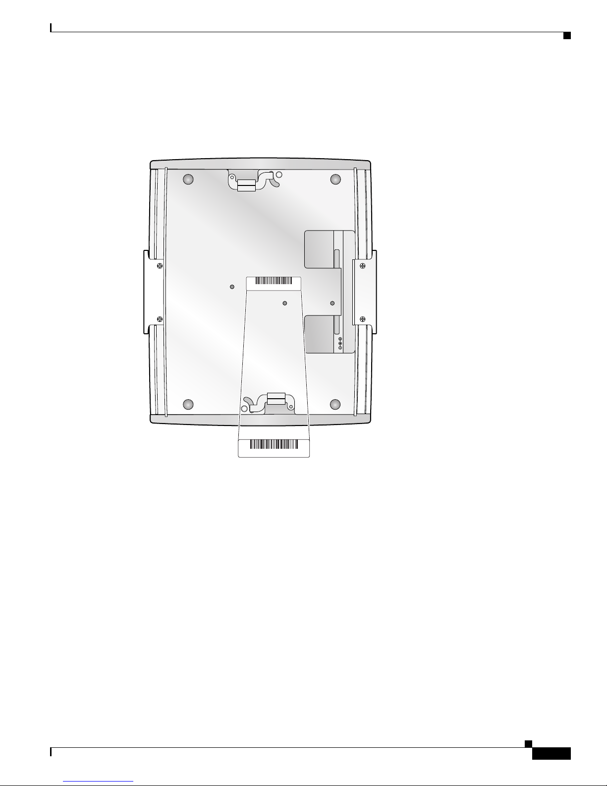
Locating the Product Serial Number
The access point serial number is located on the bottom of the access point case (see Figure 1).
Figure 1 Location of Serial Number Label
Locating the Product Serial Number
OL-8247-03
The access point serial number label contains the following information:
• Model number, such as AIR-AP1252AG-A-k9 or AIR-LAP1252AG-A-k9
• Serial number, such as VDF06367ABC (11 alphanumeric digits)
• Ethernet MAC address, such as 00abc65094f3 (12 hexadecimal digits)
• Location of manufacture, such as Made in Singapore
Cisco Aironet 1250 Series Access Point Hardware Installation Guide
xiii
Obtaining Documentation, Obtaining Support, and Security Guidelines
170544, 781-00461-01 A0
SN: NNNNNNNNN
SN: NNNNNNNNN
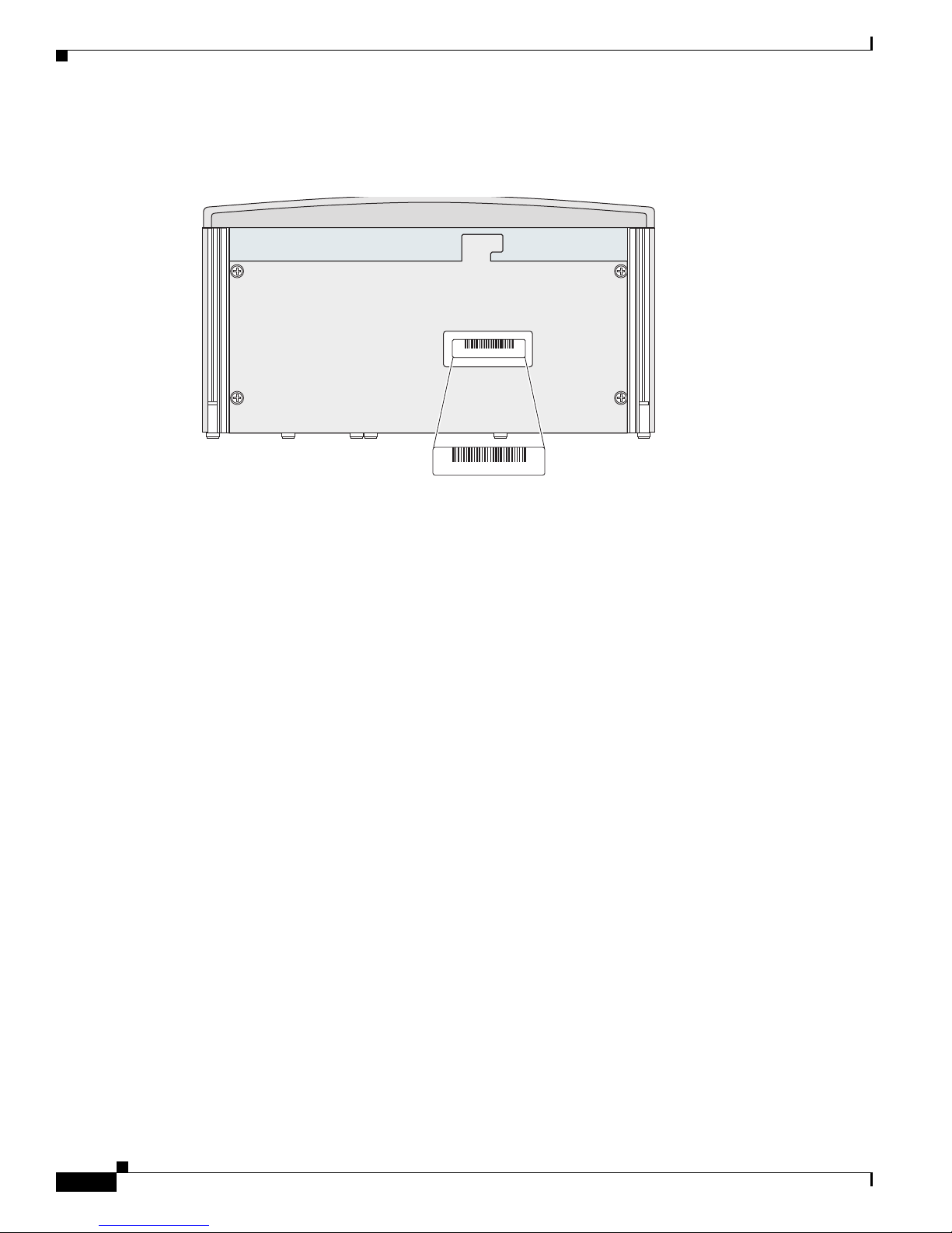
The radio module serial number is located on the bottom of the radio module case (see Figure 2).
Figure 2 Location of Radio Module Serial Number Label
Preface
The radio module serial number label contains the following information:
• Model number, such as AIR-RM1252A-A-K9 or AIR-RM1252G-A-K9
• Serial number, such as VDF06367ABC (11 alphanumeric digits)
• Radio MAC address, such as 00abc65094f3 (12 hexadecimal digits)
• Location of manufacture, such as Made in Singapore
You need your product serial number when requesting support from the Cisco Technical Assistance
Center.
Obtaining Documentation, Obtaining Support, and Security
Guidelines
For information on obtaining documentation, obtaining support, providing documentation feedback,
security guidelines, and also recommended aliases and general Cisco documents, see the monthly
What’s New in Cisco Product Documentation, which also lists all new and revised Cisco technical
documentation, at:
http://www.cisco.com/en/US/docs/general/whatsnew/whatsnew.html
Cisco Aironet 1250 Series Access Point Hardware Installation Guide
xiv
OL-8247-03

Overview
The Cisco Aironet 1250 Series Access Point is available in autonomous and lightweight configurations.
The autonomous access points can support standalone network configurations with all configuration
settings maintained within the access points. The lightweight access points operate in conjunction with
a Cisco wireless LAN controller with all configuration information maintained within the controller.
The 1250 series access point is a Wi-Fi certified, wireless LAN transceiver. The access point supports
two (draft IEEE 802.11n version 2.0) radio modules: a 2.4-GHz radio and a 5-GHz radio.
You can configure the radios separately, using different settings on each. The access point connects
wireless and wired networks or is the center point of a stand-alone wireless network. In large
installations, wireless users within radio range of an access point can roam throughout a facility while
maintaining seamless access to the network.
Product Terminology
CHAP T ER
1
The following terms refer to the autonomous and lightweight products:
• The term access point describes both autonomous and lightweight products.
• The term autonomous access point describes only the autonomous product.
• The term lightweight access point describes only the lightweight product.
• The term access point describes the product when configured to operate as an access point.
• The term bridge describes the product when configured to operate as a bridge.
Autonomous Access Points
Note Bridge mode is not supported for 802.11n or non-802.11n data rates. Also, Cisco does not recommend
configuring bridge mode on the 1250 series access point even though the commands for it are available.
The autonomous access point (model: AIR-AP1252) supports a management system based on Cisco IOS
software. The access point serves as the connection point between wireless and wired networks or as the
center point of a stand-alone wireless network. In large installations, wireless users within radio range
of an access point can roam throughout a facility while maintaining seamless access to the network.You
can configure and monitor the access point using the command-line interface (CLI), the browser-based
management system, or Simple Network Management Protocol (SNMP).
OL-8247-03
Cisco Aironet 1250 Series Access Point Hardware Installation Guide
1-1

Guidelines for Using Cisco Aironet Lightweight Access Points
Lightweight Access Points
The lightweight access point (model: AIR-LAP1252) is part of the Cisco Integrated Wireless Network
Solution and requires no manual configuration before being mounted. The lightweight access point is
automatically configured by a Cisco wireless LAN controller (hereafter called a controller) using the
Lightweight Access Point Protocol (LWAPP).
In the Cisco Centralized Wireless LAN architecture, access points operate in lightweight mode (as
opposed to autonomous mode). The lightweight access points associate to a controller. The controller
manages the configuration, firmware, and controls transactions such as 802.1x authentication. In
addition, all wireless traffic is tunneled through the controller.
LWAPP is an Internet Engineering Task Force (IETF) draft protocol that defines the control messaging
for setup and path authentication and run-time operations. LWAPP also defines the tunneling
mechanism for data traffic.
In an LWAPP environment, a lightweight access point discovers a controller by using LWAPP discovery
mechanisms and then sends it an LWAPP join request. The controller sends the lightweight access point
an LWAPP join response allowing the access point to join the controller. When the access point is
joined, the access point downloads its software if the versions on the access point and controller do not
match. After an access point joins a controller, you can reassign it to any controller on your network.
Chapter 1 Overview
LWAPP secures the control communication between the lightweight access point and controller by
means of a secure key distribution, using X.509 certificates on both the access point and controller.
This chapter provides information on the following topics:
• Guidelines for Using Cisco Aironet Lightweight Access Points, page 1-2
• Hardware Features, page 1-3
• Network Examples with Autonomous Access Points, page 1-10
Guidelines for Using Cisco Aironet Lightweight Access Points
You should keep these guidelines in mind when you use a lightweight access point:
• Lightweight access points can communicate only with Cisco controllers, such as the Cisco 2106 or
4400 series controllers. For other controllers, check with your controller documentation to ensure
your lightweight access points are supported.
• Lightweight access points do not support Wireless Domain Services (WDS) and cannot
communicate with WDS devices. However, the controller provides functionality equivalent to WDS
when the access point associates to it.
• Lightweight access points do not support Layer 2 LWAPP. They must get an IP address and discover
the controller using DHCP, DNS, or IP subnet broadcast.
• The lightweight access point console port is enabled for monitoring and debugging purposes (all
configuration commands are disabled when the access point is associated to a controller).
Cisco Aironet 1250 Series Access Point Hardware Installation Guide
1-2
OL-8247-03
Chapter 1 Overview
ETHERNET STATUS RADIO
230553
5
4
1
6
2
3
Hardware Features
Key hardware features of the access point include:
• Two radio module slots for single or dual-radio operation (see page 1-5)
• Ethernet port (see page 1-7) and console port (see page 1-8)
• LEDs, (see page 1-8)
• Multiple power sources (see page 1-8)
• UL 2043 compliance (see page 1-8)
• Anti-theft features (see page 1-9)
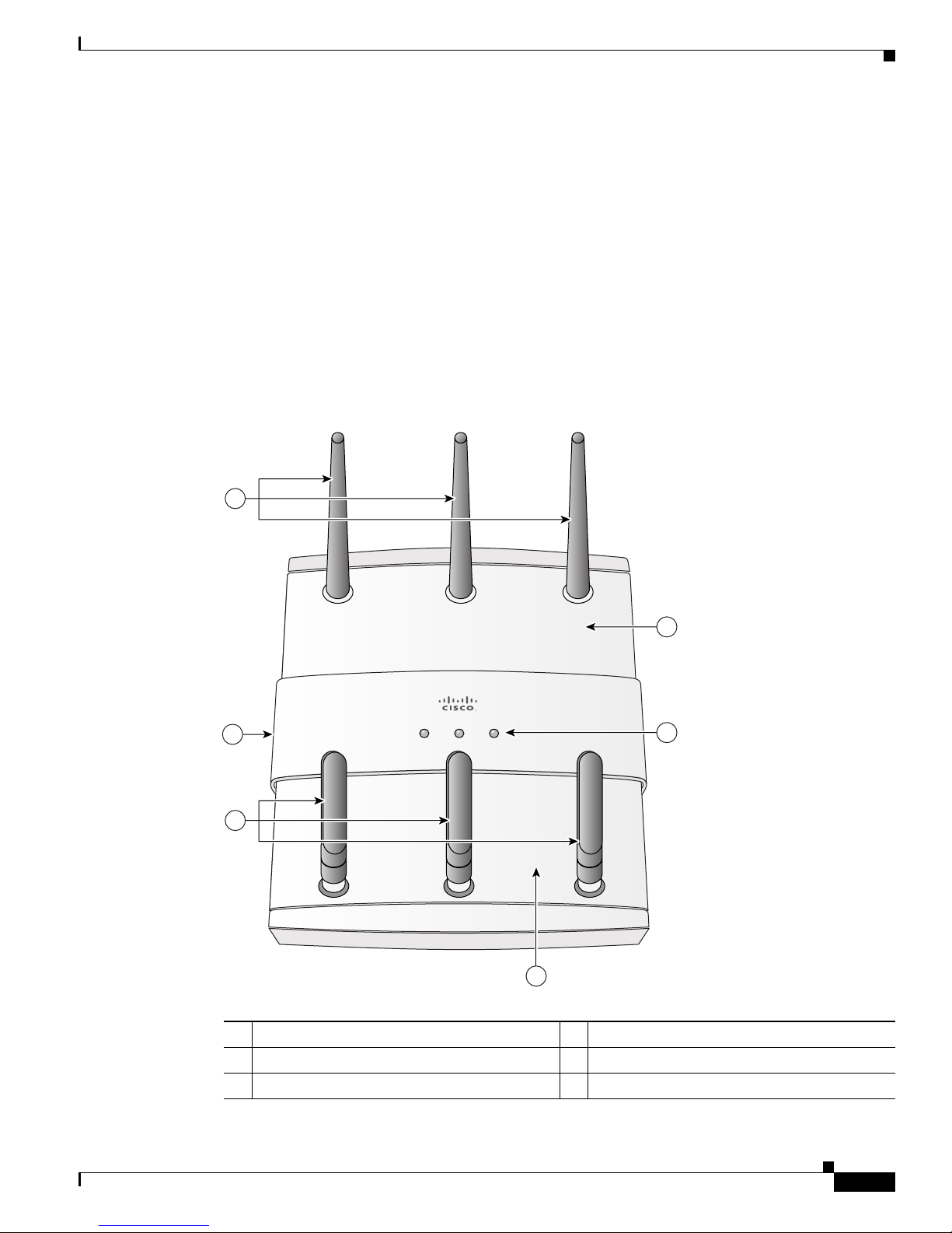
Figure 1-1 shows the access point with two radio modules installed.
Figure 1-1 Access Point with 2.4-GHz and 5-GHz Radio Modules
Hardware Features
1 2.4-GHz radio antenna 4 5-GHz radio antenna
2 Module slot 0 (2.4-GHz radio module shown) 5 Module slot 1 (5-GHz radio module shown)
3 LEDs 6 PC cable security slot
OL-8247-03
Cisco Aironet 1250 Series Access Point Hardware Installation Guide
1-3

Hardware Features
Chapter 1 Overview
Figure 1-2 illustrates a radio module. The access point supports three types of modules:
• 2.4-GHz radio module—contains a 2.4-GHz (draft IEEE 802.11n version 2.0) radio and three
antenna connectors.
• 5-GHz radio module—contains a 5-GHz (draft IEEE 802.11n version 2.0) radio and three antenna
connectors (identified with blue labels).
• Blank module—does not contain a radio or antenna connectors.
Figure 1-2 Radio Module - new pic
1 Radio antenna connector (A-Tx/Rx) 3 Radio antenna connector (B-Tx/Rx)
2 Radio antenna connector (C-Rx)
Note The 5-GHz antennas have a blue dot or blue label to correspond to the blue labels around the antenna
connectors on the 5-GHz radio module.
Cisco Aironet 1250 Series Access Point Hardware Installation Guide
1-4
OL-8247-03

Chapter 1 Overview
Radio Module Slots
The access point has two radio module slots: Slot 0 and Slot 1 (see Figure 1-1). Slot 0 can only be used
with the 2.4-GHz radio module and slot 1 can only be used with the 5-GHz radio module.
New radio configuration changes are associated with the specific module slot in which the radio module
is located. When the default radio settings are changed, the radio modules should not be moved to a
different slot. After configuration changes are made, moving the radio modules to a different modules
slot requires that you re-configuring the radio settings for that slot.
Single or Dual-Radio Operation
The access point supports single or simultaneous dual radio (draft IEEE 802.11n version 2.0) operation
using 2.4-GHz and 5-GHz radio modules. Each radio module contains an integrated radio with three
antenna connectors. A blank module is supported for single radio access point configurations.
The 2.4-GHz radio supports 802.11b, 802.11g, and 802.11n modes of operation. The 2.4-GHz radio also
supports 1 or 2 transmitting antennas and up to 3 receiving antennas.
The 5-GHz radio supports 802.11a and 802.11n modes of operation. The radio supports the Unlicensed
National Information Infrastructure (UNII-1, UNII-2, and UNII-3), and the European
Telecommunications Standards Institute
The 5-GHz radio also supports 1 or 2 transmitting antennas and up to 3 receiving antennas.
Hardware Features
/ industrial, scientific and medical (ETSI/ISM) frequency bands.
Operating Modes
The 2.4-GHz radio module supports four operating modes:
• 802.11b single transmit antenna
• 802.11g single transmit antenna
• 802.11n HT-20 MHz with dual transmit antennas
• 802.11n HT-40 MHz with dual transmit antennas
The 5-GHz radio module supports three operating modes:
• 802.11a single transmit antenna
• 802.11n HT-20 MHz with dual transmit antennas
• 802.11n HT-40 MHz with dual transmit antennas
Spatial Multiplexing
The radio modules can support two transmitters to achieve faster data rates for a given bandwidth. This
technique is called multiple input multiple output (MIMO) and relies on the premise that, via multi-path,
two transmitted signals take different paths to the receivers. Using special data packet features allows
the receivers to distinguish between the two transmitted signals and increases the access point data rate.
OL-8247-03
Cisco Aironet 1250 Series Access Point Hardware Installation Guide
1-5

Hardware Features
Maximum Ratio Combining
The radio modules use three receivers to support maximum ratio combining (MRC) to enhance receiver
performance. MRC is a technique that combines the signals from multiple receivers in a manner to
optimize the signals. MRC can provide up to 3 dB of increased receive signal strength in all modes of
operation.
Antennas Supported
Table 1-1 lists the supported access point antennas.
Chapter 1 Overview
Warning
Note The access point has been designed to operate with the antennas listed below and having a maximum
The access point, antennas, and all interconnected equipment including the associated LAN
connections must be located indoors within the same building.
Statement 375
gain of 10 dBi for 2.4 GHz and 6 dBi for 5 GHz. Antennas not included in this list or having a higher
gain are strictly prohibited for use with the access point. The required antenna impedance is 50 ohms.
Note To reduce potential radio interference to other users, the antenna type and its gain should be chosen so
that the equivalent isotropically radiated power (e.i.r.p.) is not more than required for successful
communication.
Table 1-1 Supported Antennas
AIR-ANT5959
2.4-GHz Antennas
1
diversity ceiling omnidirectional
Gain
(dBi) 5-GHz Antennas
2 AIR-ANT5135DG-R non-articulated omnidirectional 3.5
Gain
(dBi)
AIR-ANT2422DG-R non-articulated dipole 2.2 AIR-ANT5135D-R articulating dipole 3.5
AIR-ANT4941 articulating dipole 2.2 AIR-ANT5140V-R omnidirectional 4
AIR-ANT2430V-R omnidirectional 3 AIR-ANT5145V-R
AIR-ANT1728 ceiling omnidirectional 5.2 AIR-ANT5160V-R
1
diversity ceiling omnidirectional 4.5
1
omnidirectional 6
AIR-ANT2506 mast mount omnidirectional 5.2
AIR-ANT3213 diversity pillar omnidirectional 5.2
AIR-ANT2460P-R
AIR-ANT2465P-R
AIR-ANT2485P-R
AIR-ANT2410Y-R
1. The antenna has an attached UL2043 rated antenna cable.
1
ceiling omnidirectional 6
1
diversity patch directional 6.5
1
patch directional 8.5
yagi directional 10
Cisco Aironet 1250 Series Access Point Hardware Installation Guide
1-6
OL-8247-03
Chapter 1 Overview
230554
ETHERNET CONSOLE MODE+56VDC
1 2 3 4
CAUTION
EXTERNAL DC AND INLINE PoE
POWER SOURCE REQUIREMENTS
DETERMINED BY INSTALLED
RADIO MODULES
REFER TO
PRODUCT DOCUMENTATION
LEDs
Ethernet Port
Hardware Features
The access point has three LEDs (see Figure 1-1) to indicate Ethernet activity, radio activity, and status
indications (refer to the “Checking the Autonomous Access Point LEDs” section on page 3-2 or the
“Checking the Lightweight Access Point LEDs” section on page 4-3 for additional information).
• The Status LED provides general operating status and error indications.
• The Ethernet LED signals Ethernet traffic on the wired Ethernet LAN and provides Ethernet error
indications.
• The Radio LED signals that wireless packets are being transmitted or received over the radio
interface and provides error indications.
The Ethernet port is located on the bottom of the unit in the access point connector area (see Figure 1-3).
The auto-sensing Ethernet port accepts an RJ-45 connector, linking the access point to your 10BASE-T,
100BASE-T, or 1000BASE-T Ethernet LAN. The Ethernet interface supports automatic media
dependent interface crossover (MDIX) detection, which automatically senses cable type
(straight-through or crossover) and adjusts the internal connections appropriately. Also the interface
automatically senses the data rate being received over the connected cable.
The access point can receive power through the Ethernet cable from a 1250 series power injector. The
Ethernet MAC address is printed on the label on the bottom of the access point.
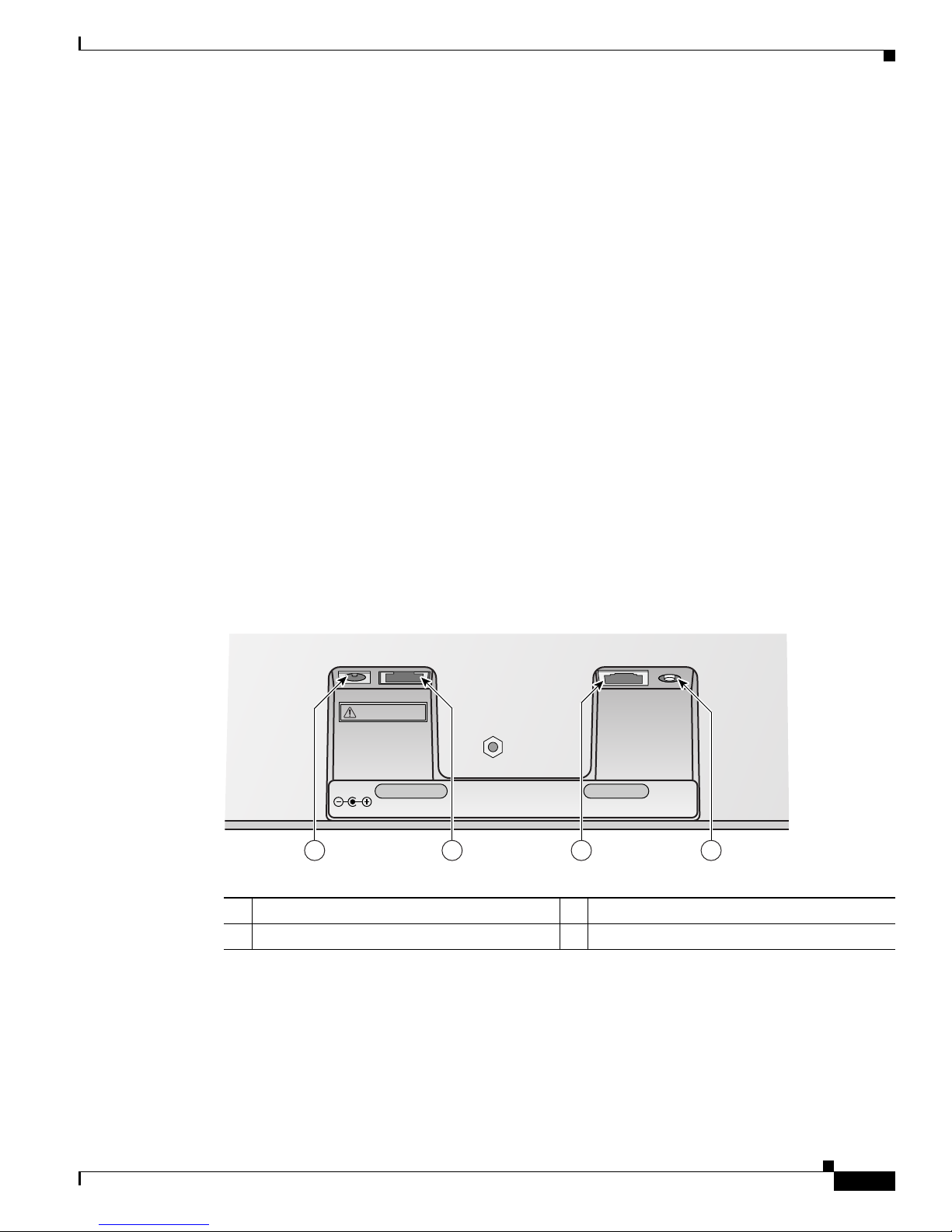
Figure 1-3 Access Point Connector Area
1 DC power connector (+56 VDC) 3 Console port (RJ-45)
2 Ethernet port (RJ-45) 4 MODE button
OL-8247-03
Cisco Aironet 1250 Series Access Point Hardware Installation Guide
1-7

Hardware Features
Console Port
The console port is located on the bottom of the unit in the access point connector area (see Figure 1-3).
The console port provides access to the access point’s command-line interface (CLI) using a terminal
emulator program. Use an RJ-45 to DB-9 serial cable to connect your computer’s COM port to the access
point’s serial console port. Assign the following port settings to a terminal emulator to open the
management system pages: 9600 baud, 8 data bits, no parity, 1 stop bit, and no flow control.
Note After completing your configuration changes, you must remove the serial cable from the access point.
The serial cable can be purchased from Cisco (part number AIR-CONCAB1200) or can be built using
the pinouts in Appendix E, “Console Cable Pinouts.”
Power Sources
The access point can receive power from a 1250 series DC power module or from inline power using the
Ethernet cable. The access point supports the IEEE 802.3af inline power standard and Cisco CDP Power
Negotiation. Using inline power, you do not need to run a power cord to the access point because power
is supplied over the Ethernet cable.
The access point supports the following power sources:
Chapter 1 Overview
• Cisco Aironet 1250 series DC power module (AIR-PWR-SPLY1)
• Inline power:
–
–
Note Current switches and patch panels do not provide enough power to operate the access point with both
2.4-GHz and 5-GHz radios. At power-up, if the access point is unable to determine that the power source
can supply sufficient power, the access point automatically deactivates both radios to prevent an
over-current condition. The access point also activates a Status LED low power error indication and
creates an error log entry (refer to the “Checking the Autonomous Access Point LEDs” section on
page 3-2 or the “Checking the Lightweight Access Point LEDs” section on page 4-3).
UL 2043 Compliance
The access point has adequate fire resistance and low smoke-producing characteristics suitable for
operation in a building's environmental air space, such as above suspended ceilings, in accordance with
Section 300-22(c) of the NEC, and with Sections 2-128, 12-010(3) and 12-100 of the Canadian
Electrical Code, Part 1, C22.1.
Caution The 1250 series power injector (AIR-PWRINJ4), the 1250 series DC power module
(AIR-PWR-SPLY1), and the antennas are not tested to UL 2043 and should not be placed in a building’s
environmental air space, such as above suspended ceilings.
Cisco Aironet 1250 series power injector (AIR-PWRINJ4)
IEEE 802.3af power source (access point with only one radio module installed)
Cisco Aironet 1250 Series Access Point Hardware Installation Guide
1-8
OL-8247-03
Chapter 1 Overview
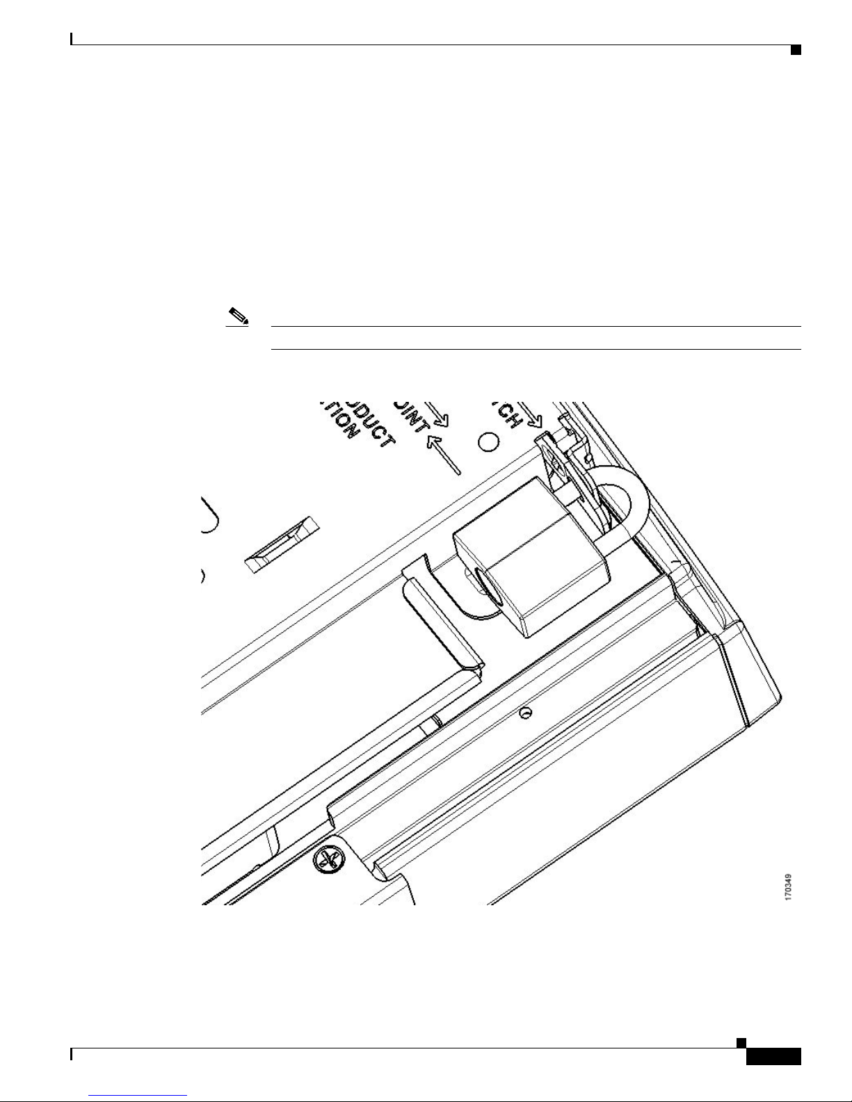
Anti-Theft Features
There are two methods of securing the access point:
• Padlock—You can lock the access point to the mounting plate with a padlock (see Figure 1-4). This
prevents removing the radio modules and blocks access to the access point connector area.
Compatible padlocks are Master Lock models 120T and 121T or equivalent. For additional
information, refer to the “Securing the Access Point” section on page 2-27.
• Security cable keyhole—You can use the security cable slot (see Figure 1-1) to secure the access
point using a standard security cable, like those used on laptop computers (refer to the “Securing the
Access Point” section on page 2-27).
Note The mounting plate and padlock are required to prevent removal of the radio modules.
Figure 1-4 Access Point with Padlock-
Hardware Features
OL-8247-03
Cisco Aironet 1250 Series Access Point Hardware Installation Guide
1-9

Network Examples with Autonomous Access Points
Access point
Access point
135445
Network Examples with Autonomous Access Points
This section describes the access point’s role in three common wireless network configurations. The
access point’s default configuration is as a root unit connected to a wired LAN or as the central unit in
an all-wireless network. The repeater role requires a specific configuration.
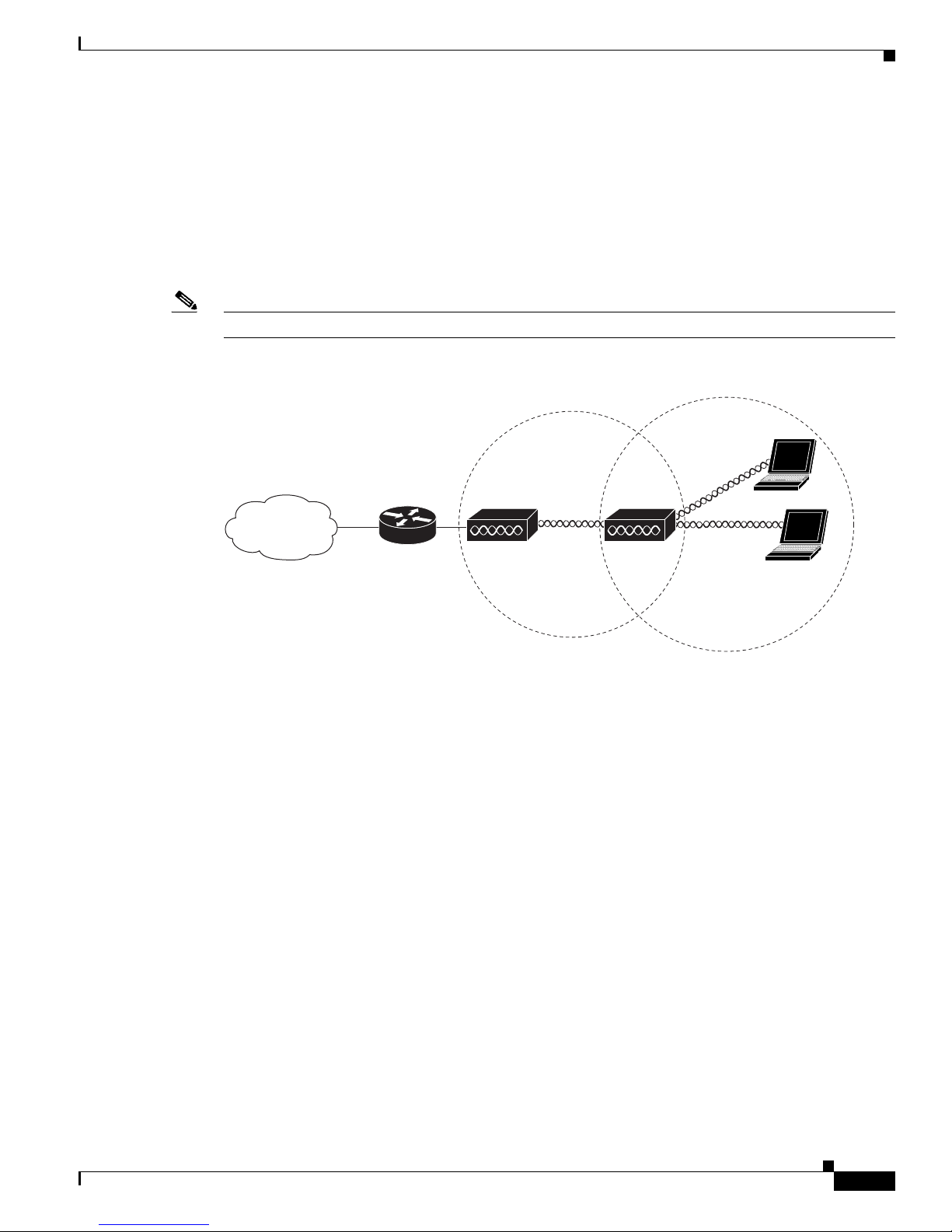
Root Unit on a Wired LAN
An access point connected directly to a wired LAN provides a connection point for wireless users. If
more than one access point is connected to the LAN, users can roam from one area of a facility to another
without losing their connection to the network. Figure 1-5 shows access points acting as root units on a
wired LAN.
Figure 1-5 Access Points as Root Units on a Wired LAN
Chapter 1 Overview
Cisco Aironet 1250 Series Access Point Hardware Installation Guide
1-10
OL-8247-03
Chapter 1 Overview
Access point Repeater
135444
Repeater Unit that Extends Wireless Range
An access point can be configured as a stand-alone repeater to extend the range of your infrastructure or
to overcome an obstacle that blocks radio communication. The repeater forwards traffic between
wireless users and the wired LAN by sending packets to either another repeater or to an access point
connected to the wired LAN. The data is sent through the route that provides the best performance for
the client. Figure 1-6 shows an access point acting as a repeater. Consult the Cisco IOS Software
Configuration Guide for Cisco Aironet Access Points for instructions on setting up the roles.
Note Non-Cisco client devices might have difficulty communicating with repeater access points.
Figure 1-6 Access Point as Repeater
Network Examples with Autonomous Access Points
OL-8247-03
Cisco Aironet 1250 Series Access Point Hardware Installation Guide
1-11
Network Examples with Autonomous Access Points
Access point
135443
Access point
Workgroup bridge
135448
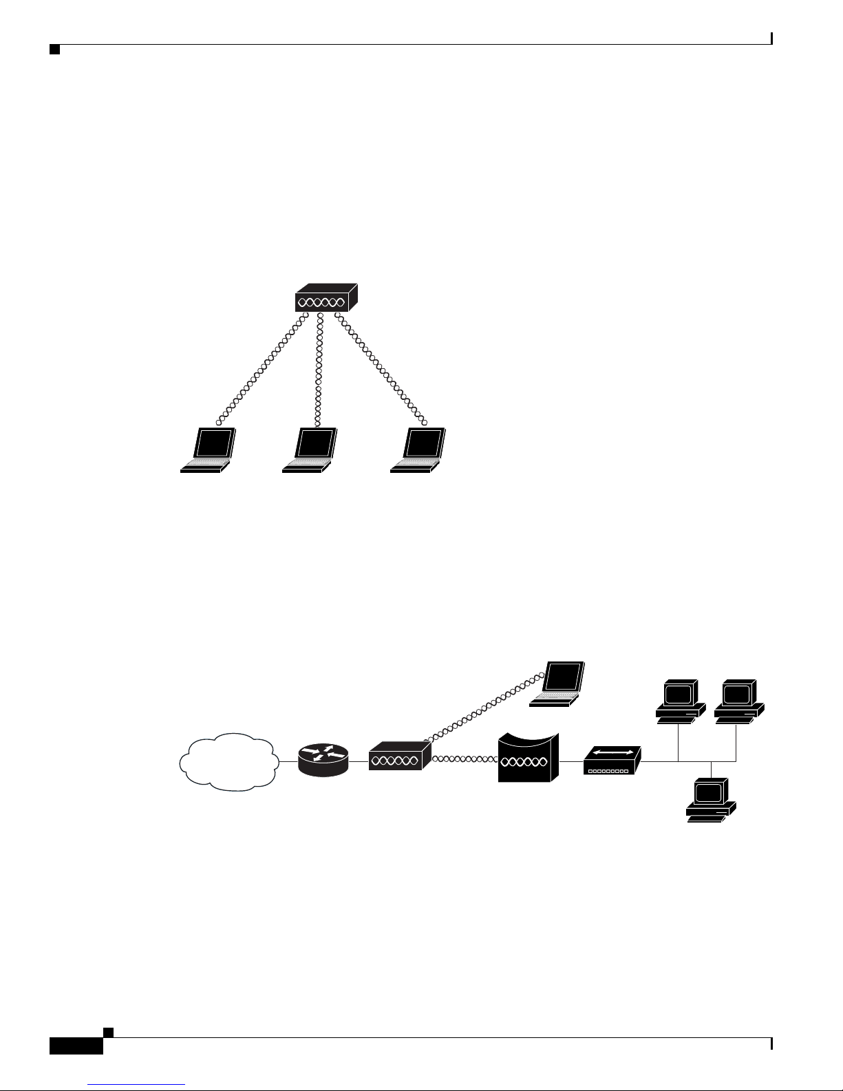
Central Unit in an All-Wireless Network
In an all-wireless network, an access point acts as a stand-alone root unit. The access point is not
attached to a wired LAN; it functions as a hub linking all stations together. The access point serves as
the focal point for communications, increasing the communication range of wireless users. Figure 1-7
shows an access point in an all-wireless network.
Figure 1-7 Access Point as Central Unit in All-Wireless Network
Chapter 1 Overview
Workgroup Bridge Network
The access point supports a workgroup bridge role to interconnect remote Ethernet workstations to the
main LAN. The workgroup bridge can communicate with an access point (see Figure 1-8) or with a
bridge (see Figure 1-9).
Figure 1-8 Workgroup Bridge Communicating with an Access Point
Cisco Aironet 1250 Series Access Point Hardware Installation Guide
1-12
OL-8247-03
Chapter 1 Overview
Bridge Workgroup
bridge
135499
158085
LWAPP
LWAPP
Network Example with Lightweight Access Points
Figure 1-9 Workgroup Bridge Communicating with a Bridge
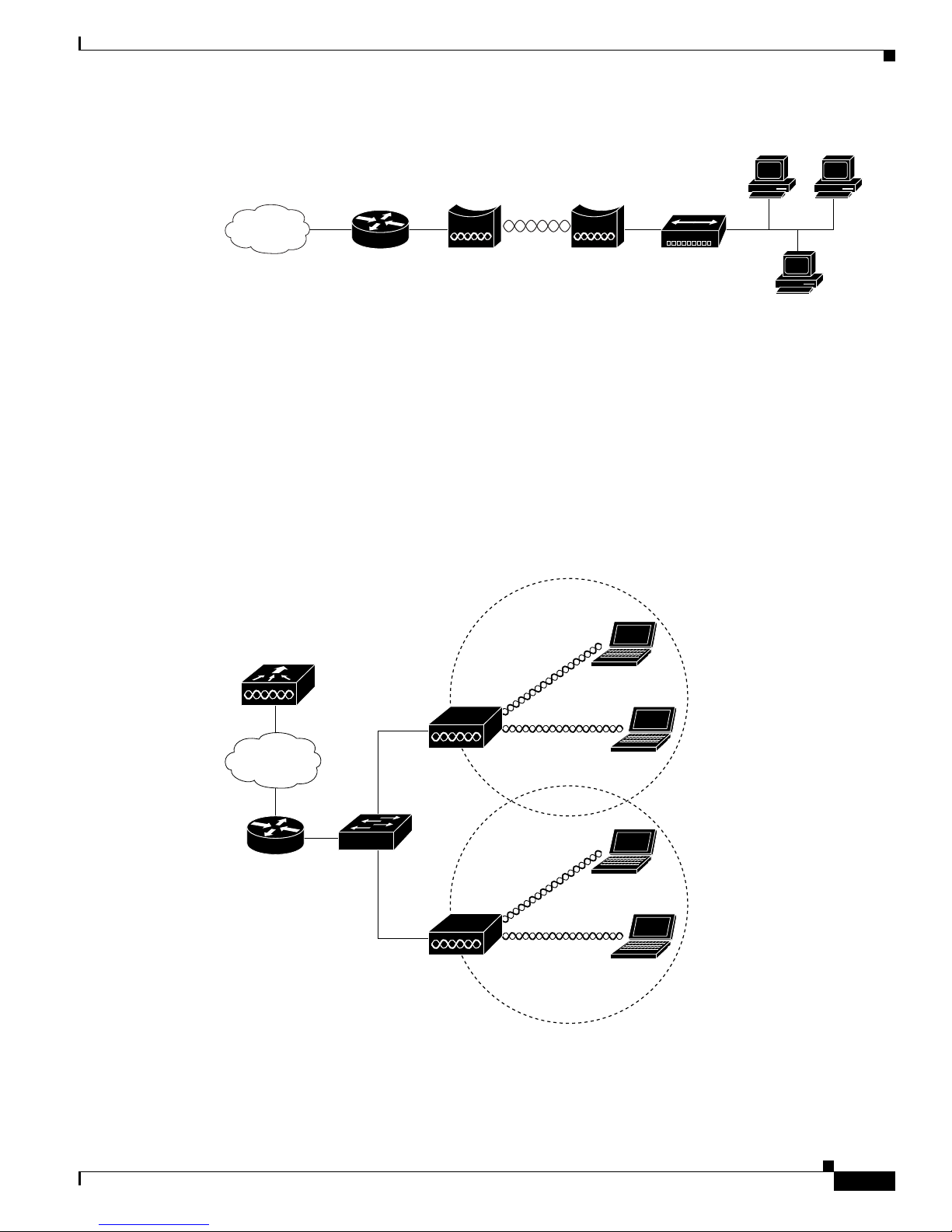
Network Example with Lightweight Access Points
The lightweight access points support Layer 3 network operation. Lightweight access points and
controllers in Layer 3 configurations use IP addresses and UDP packets, which can be routed through
large networks. Layer 3 operation is scalable and recommended by Cisco.
This section illustrates a typical wireless network configuration containing lightweight access points and
a Cisco Wireless LAN Controller (see Figure 1-5). Consult the Cisco Wireless LAN Controller
Configuration Guide for instructions on setting up the lightweight access points.
Figure 1-10 Typical Lightweight Access Point Network Configuration Example
OL-8247-03
Cisco Aironet 1250 Series Access Point Hardware Installation Guide
1-13

Network Example with Lightweight Access Points
Chapter 1 Overview
Cisco Aironet 1250 Series Access Point Hardware Installation Guide
1-14
OL-8247-03

CHAP T ER
2
Installing the Access Point
This chapter describes the installation of the access point and includes these sections:
• Safety Information, page 2-2
• Warnings, page 2-2
• Unpacking the Access Point, page 2-3
• Basic Installation Guidelines, page 2-4
• Before Beginning the Installation, page 2-4
• Installation Summary, page 2-5
• Mounting Overview, page 2-5
• Mounting on a Horizontal or Vertical Surface, page 2-7
• Mounting Below a Suspended Ceiling, page 2-9
• Mounting Above a Suspended Ceiling, page 2-11
• Mounting to a Network Cable Box, page 2-18
• Mounting on a Desktop or Shelf, page 2-19
• Connecting the Ethernet and Power Cables, page 2-20
• Powering Up the Access Point, page 2-22
• Installing the Access Point to the Mounting Plate, page 2-24
• Securing the Access Point, page 2-27
• Removing the Access Point From the Mounting Plate, page 2-30
• Removing a Radio Module, page 2-32
• Inserting a Radio Module, page 2-34
OL-8247-03
Cisco Aironet 1250 Series Access Point Hardware Installation Guide
2-1

Safety Information
Safety Information
Follow the guidelines in this section to ensure proper operation and safe use of the access point.
FCC Safety Compliance Statement
The FCC with its action in ET Docket 96-8 has adopted a safety standard for human exposure to radio
frequency (RF) electromagnetic energy emitted by FCC certified equipment. When used with approved
Cisco Aironet antennas, Cisco Aironet products meet the uncontrolled environmental limits found in
OET-65 and ANSI C95.1, 1991. Proper installation of this radio according to the instructions found in
this manual will result in user exposure that is substantially below the FCC recommended limits.
General Safety Guidelines
Do not hold any component containing a radio so that the antenna is very close to or touching any
exposed parts of the body, especially the face or eyes, while transmitting.
Chapter 2 Installing the Access Point
Warnings
Warning
Warning
Warning
Warning
Translated versions of the following safety warnings are provided in Appendix A, “Translated Safety
Warnings.”
This warning symbol means danger. You are in a situation that could cause bodily injury. Before you
work on any equipment, be aware of the hazards involved with electrical circuitry and be familiar
with standard practices for preventing accidents. Use the statement number provided at the end of
each warning to locate its translation in the translated safety warnings that accompanied this device.
Statement 1071
SAVE THESE INSTRUCTIONS
Read the installation instructions before you connect the system to its power source.
This product relies on the building’s installation for short-circuit (overcurrent) protection. Ensure that
the protective device is rated not greater than: 20A
Do not operate your wireless network device near unshielded blasting caps or in an explosive
environment unless the device has been modified to be especially qualified for such use.
Statement 245B
Statement 1005
Statement 1004
Warning
Cisco Aironet 1250 Series Access Point Hardware Installation Guide
2-2
In order to comply with FCC radio frequency (RF) exposure limits, antennas should be located at a
minimum of 7.9 inches (20 cm) or more from the body of all persons.
Statement 332
OL-8247-03
 Loading...