

Cisco AIR-AP1220B-A-K9 - Aironet 1200 - Wireless Access Point, Aironet AIR-AP1200 Hardware Installation Manual

Corporate Headquarters
Cisco Systems, Inc.
170 West Tasman Drive
San Jose, CA 95134-1706
USA
http://www.cisco.com
Tel: 408 526-4000
800 553-NETS (6387)
Fax: 408 526-4100
Cisco Aironet 1200 Series Access Point
Hardware Installation Guide
Customer Order Number:
Text Part Number: OL-2155-02

THE SPECIFICATIONS AND INFORMATION REGARDING THE PRODUCTS IN THIS M ANUAL ARE SUBJECT TO CHA NGE WITHOUT NO TICE. ALL
STATEMENTS, INFORMATION, AND RECOMMENDATIONS IN THIS MANUAL ARE BELIEVED TO BE ACCURATE BUT ARE PRESENTED WITHOUT
WARRANTY OF ANY KIND, EXPRESS OR IMPLIED. USERS MUST TAKE FULL RESPONSI BILITY FOR THEIR APPLICA TION OF ANY PRODUCT S.
THE SOFTWARE LICENSE AND LIMITED WARRANTY FOR THE ACCOMPANYING PRODUCT ARE SET FORT H IN THE INFORMATION PACKET T HAT
SHIPPED WITH THE PRODUCT AND ARE INCORPORATED HEREIN BY THIS REFERENCE. IF YOU ARE UNABLE TO LOCATE THE SOFTWARE LICENSE
OR LIMITED WARRANTY, CONTACT YOUR CISCO REPRESENTATIVE FOR A COPY.
The following information is for FCC compliance of Class A devices: This equipment has been tested and found to comply with the limits for a Class A digital device, pursuant
to part 15 of the FCC rules. These limits are designed to provide reasonable protection against harmful interference when the equipment is operated in a commercial
environment. This equipment generates, uses, and can radiate radio-frequency energy and, if not installed and used in accor dance with the instruction manual, may cause
harmful interference to radio communications. Operation of this equipment in a residential area is likely to cause harmful interference, in which case users will be required
to correct the interference at their own expense.
The following information is for FCC compliance of Class B devices: The equipment described in this manual generates and may radiate radio-frequency energy. If it is not
installed in accordance with Cisco’s installation instructions, it may cause interference with radio and television reception. This equipment has been tested and found to
comply with the limits for a Class B digital device in accordance with the specifications in part 15 of the FCC rules. These specifications are designed to provide reasonable
protection against such interference in a residential installation. However, there is no guarantee that interference will not occur in a particular installation.
Modifying the equipment without Cisc o’s writ ten author ization m ay resul t in the equi pment no lo nger comp lyi ng with FCC requi rements for Class A or Class B digital
devices. In that event, your right to use the equ ipment may be limit ed by FCC regul ations , and you may be requir ed to correct a ny interference to radio or television
communications at your own expense.
You can determine whether your equipment is causing interference by turning it off. If the interferen ce stops, it was probably caused by the Cisco equipment or one of its
peripheral devices. If the equipment causes interference to radio or television reception, try to correct the interference by using one or more of the followi ng measures:
• Turn the television or radio antenna unt il the int erference st ops.
• Move the equipment to one side or the other of the televisio n or radi o.
• Move the equipment farther away from the te levision or radio.
• Plug the equipment into an outlet that is on a di fferent cir cuit from the televi sion o r radio. (That is, make certain th e equipment and the te levision or radio are on circuit s
controlled by different circuit breaker s or fuses.)
Modifications to this product no t author ized by Cis co Syst ems, Inc. coul d voi d the FCC appro val and ne gate your authorit y to op erate the pr odu ct.
The Cisco implementation of TCP head er compressi on is an adap tation of a program developed by the Universi ty of Ca lifornia, Berk eley (UCB) as part of UCB ’s public
domain version of the UNIX operatin g system. All rights reserved . Copyri ght © 1981 , Rege nts of the Uni versity of Calif ornia.
NOTWITHSTANDING ANY OTHER WARRANTY HEREIN, ALL DOCUMENT FILES AND SOFTWARE OF THE SE SUPPLIERS ARE PROVIDED “AS IS” WITH
ALL FAULTS. CISCO AND THE ABOVE-NAMED SUPPLIERS DISCLAI M ALL WARRANTIE S, EXPRESSED OR IMPLIED, INCLUDING, WITHOUT
LIMITATION, THOSE OF MERCHANTABILITY, FITNESS FOR A PARTICULAR PURPOSE AND NO NINFRINGEM ENT OR ARISING FROM A COURS E OF
DEALING, USAGE, OR TRADE PRACTICE.
IN NO EVENT SHALL CISCO OR ITS SUPPLIERS BE LIABLE FOR ANY INDIRECT, SPECIAL, CONSEQUENTIAL, OR INCIDENTAL DAMAGES, INCLUDING ,
WITHOUT LIMITATION, LOST PROFITS OR LOSS OR DAMAGE TO DATA ARISING OUT OF THE USE OR INABILITY TO USE THIS MANUAL, EVEN IF CISCO
OR ITS SUPPLIERS HAVE BEEN ADVISED OF THE POSSIBILITY OF SUCH DAMAGE S.
Cisco Aironet 1200 Series Access Point Hardware Installation Guide
Copyright © 2002, Cisco Systems, I nc.
All rights reserved.
CCIP, the Cisco Arrow logo, the Cisco Powered Network mark, the Cisco Systems Verified logo, Cisco Unity, Follow Me Browsing, FormShare, Internet Quotient, iQ
Breakthrough, iQ Expertise, iQ FastTrack, the iQ Logo, iQ Net Readiness Scorecard, Networking Academy, ScriptShare, SMARTnet, TransPath, and Voice LAN are trademarks
of Cisco Systems, Inc.; Changing the Way We Work, Live, Play, and Learn, Discover All That’s Possible, The Fastest Way to Increase Your Internet Quotient, and iQuick Study are
service marks of Cisco Systems, Inc.; and Aironet, ASIST, BPX, Catalyst, CCDA, CCDP, CCIE, CCNA, CCNP, Cisco, the Cisco Certified Internetwork Expert logo, Cisco IOS,
the Cisco IOS logo, Cisco Press, Cisco Systems, Cisco Systems Capital, the Cisco Systems logo, Empowering the Internet Generation, Enterprise/Solver, EtherChannel,
EtherSwitch, Fast Step, GigaStack, IOS, IP/TV, LightStream, MGX, MICA, the Networkers logo, Network Registrar, Packet, PIX, Post-Routing, Pre-Routing, RateMUX,
Registrar, SlideCast, StrataView Plus, Stratm, SwitchProbe, TeleRouter, and VCO are registered trademarks of Cisco Systems, Inc. and/or its affiliates in the U.S. and certain other
countries.
All other trademarks mentioned in this document or Web site are the property of their respective owners. The use of the word partner does not imply a partnership relationship
between Cisco and any other company. (0206R)

iii
Cisco Aironet 1200 Series Access Point Hardware Installation Guide
OL-2155-02
CONTENTS
Preface vii
Objectives vii
Audience vii
Organization vii
Conventions viii
Related Publications viii
Obtaining Documentation ix
World Wide Web ix
Documentation CD-ROM ix
Ordering Documentation ix
Documentation Feedback x
Obtaining Technical Assistance x
Cisco.com x
Technical Assistance Center xi
Cisco TAC Web Site xi
Cisco TAC Escalation Center xi
CHAPTER
1 Overview 1-1
Key Features 1-2
Dual-Band Radio Support 1-2
2.4-GHz Mini-PCI Radio Card 1-2
5-GHz Radio Module 1-2
Power 1-3
Antenna Connectors 1-4
2.4-GHz Radio 1-4
Ethernet and Console Ports 1-4
Ethernet Port 1-4
Console Port 1-4
Metal Enclosure 1-4
Indicators 1-5
Security Lock Feature 1-6
Network Configuration Examples 1-7
Root Unit on a Wired LAN 1-7
Repeater Unit That Extends Wireless Range 1-8

Contents
iv
Cisco Aironet 1200 Series Access Point Hardware Installation Guide
OL-2155-02
Central Unit in an All-Wireless Network 1-9
Access Point Specifications 1-10
CHAPTER
2 Installation 2-1
Safety Information 2-2
FCC Safety Compliance Statement 2-2
General Safety Guidelines 2-2
Warnings 2-3
Installation Guidelines 2-4
Basic Guidelines 2-4
Installation Above Suspended Ceilings 2-4
Coverage Options 2-5
Minimal Overlap Coverage Option 2-5
Heavy Overlap Coverage Option 2-5
Site Surveys 2-6
Unpacking the Access Point 2-6
Package Contents 2-7
Before Beginning the Installation 2-7
Installation Summary 2-8
Connecting the 2.4-GHz Antennas 2-8
Connecting the Ethernet and Power Cables 2-9
CHAPTER
3 Basic Configuration 3-1
Before You Start 3-2
Summary of Configuration Steps 3-2
Using the IP Setup Utility 3-3
Obtaining and Installing IPSU 3-3
Finding the Access Point’s IP Address 3-3
Setting the Access Point IP Address and SSID 3-4
Entering Basic Settings 3-6
Using an Internet browser 3-6
Using a Terminal Emulator 3-9
Selecting Pages and Settings 3-9
Applying Changes to the Configuration 3-9
Assigning Basic Settings 3-9
Default Basic Settings 3-13

Contents
v
Cisco Aironet 1200 Series Access Point Hardware Installation Guide
OL-2155-02
CHAPTER
4 Mounting Instructions 4-1
Overview 4-2
Mounting on a Horizontal or Vertical Surface 4-3
Mounting on a Suspended Ceiling 4-4
Attaching the Access Point to the Mounting Bracket 4-5
Securing the Access Point to the Mounting Bracket 4-5
CHAPTER
5 2.4-GHz Radio Upgrade 5-1
Overview 5-2
Unpacking the Radio 5-2
Opening the Access Cover 5-3
Removing a Blank Spacer Card 5-4
Removing a 2.4-GHz Radio 5-5
Installing a 2.4-GHz Radio 5-7
CHAPTER
6 5-GHz Radio Module Upgrade 6-1
Overview 6-2
Unpacking the Radio Module 6-2
Removing the 5-GHz Radio Access Cover 6-2
Removing a 5-GHz Radio Module 6-3
Installing a 5-GHz Radio Module 6-5
CHAPTER
7 Troubleshooting 7-1
Checking the Top Panel Indicators 7-2
Checking Basic Settings 7-3
SSID 7-3
WEP Keys 7-4
Security Settings 7-4
Resetting to the Default Configuration 7-4
APPENDIX
A Translated Safety Warnings A-1
Dipole Antenna Installation Warning A-2
Explosive Device Proximity Warning A-3
Installation and Grounding Warning A-4
Lightning Activity Warning A-6
Installation Warning A-7

Contents
vi
Cisco Aironet 1200 Series Access Point Hardware Installation Guide
OL-2155-02
Circuit Breaker (15A) Warning A-8
APPENDIX
B Declarations of Conformity and Regulatory Information B-1
Manufacturers Federal Communication Commission Declaration of Conformity Statement B-2
Department of Communications—Canada B-3
Canadian Compliance Statement B-3
European Community, Switzerland, Norway, Iceland, and Liechtenstein B-4
Declaration of Conformity with Regard to the R&TTE Directive 1999/5/EC B-4
Declaration of Conformity for RF Exposure B-6
Guidelines for Operating Cisco Aironet Access Points in Japan B-6
Japanese Translation B-6
English Translation B-7
APPENDIX
C Console Cable Pinouts C-1
Overview C-2
Console Port Signals and Pinouts C-2
APPENDIX
D Channels and Antenna Settings D-1
Channels D-2
IEEE 802.11b (2.4 GHz Band) D-2
IEEE 802.11a (5-GHz Band) D-3
Maximum Power Levels and Antenna Gains D-4
IEEE 802.11b (2.4 GHz Band) D-4
IEEE 802.11a (5-GHz Band) D-6
I
NDEX

vii
Cisco Aironet 1200 Series Access Point Hardware Installation Guide
OL-2155-02
Preface
This section describes the objectives, audience, organization, and conventions of the Cisco Aironet 1200
Series Access Point Hardware Installation Guide.
Objectives
This publication explains the steps for initial setup and basic configuration of the single or dual-band
access point supporting 2.4 -GHz an d 5-GHz operation . This pub licatio n also provides trouble shoot ing
information and detailed specifications.
Audience
This publication is fo r the pe rso n in stall ing an d con figuring a C isc o A iron et 1200 Seri es A cce ss Point
for the first time. The installer should be familiar with network structures, terms, and concepts.
Organization
This guide contains the following secti ons:
Chapter 1, “Ove rv i ew,” describes the features and specifications of access points.
Chapter 2, “Inst allati on,” provides basic installation instructions.
Chapter 3, “Bas ic C onfigura tion ,” describes how to enter basic configuration setting s.
Chapter 4, “Mo unting In structi ons,” provides mounting instruc tions for the ac cess point.
Chapter 5, “2.4-GHz Radio Upgrade,” provides instructions for installing, upgrading, and removing the
2.4-GHz mini-PCI radio c ard.
Chapter 6, “5-G Hz Radi o M odule Up gra de,” provides instructions for installing and removing the
5-GHz radio module.
Chapter 7, “Troubleshooti ng,” provides solutions to pot entia l p roblem s e ncoun ter ed du ring se tup.
Appendix A, “Translated Safety Warnings,” lists translations of the safety warnings in this publication.
Appendix B, “Declarations of Conf ormi ty a nd Regula tory I nform at ion, ” describes the regula tory
conventions to which the access point confor ms and provides guidelin es for oper ating acce ss points in
Japan.

viii
Cisco Aironet 1200 Series Access Point Hardware Installation Guide
OL-2155-02
Preface
Conventions
Appendix C, “Console Cable Pinouts,” describes the pinouts for the serial RJ-45 to DB-9 console cable
that connects to the access point’s serial console port.
Appendix D, “Channels and Ant enna Sett ings, ” describes the channels and antenna settings supported
by the regulatory organizations.
Conventions
This publication uses the following conventions to convey instructions and informa tion:
• Commands and keywords are in boldface type.
Note Means reader take note. Notes contain helpful suggestions or references to materials not contained in
this manual.
Caution Means rea der be c are ful. In this situation, you might do something that could result in equipment
damage or loss of data.
Warning
The warning symbol means danger.
Y ou are in a situation that could cause bodily injury . Before you
work on an y equ ipme nt, be aw are of the h aza rds inv olv ed w ith elec tric al cir cuitry and be fa milia r
with standard practi ces f or pr eventing accidents. To see translations of th e warnings that a ppear
in this publication, refer to Appendix A in this manual.
Related Publications
For more information about access points and related products, refer to the following publications:
• Quick Start Guide: Cis co A ironet 1200 Seri es A cce ss Point describes how to attach antennas and
cables, mount the acc ess point , and how to obtain acc ess point docum entat ion. This documen t is
included in the sh ipping bo x with you r acc ess poi nt.
• Cisco Aironet 1200 Series Access Point Software Configuration Guide describes the access point’s
management system and explains how to configure the access point. This doc ument is available on
the Cisco CCO web site at the following URL:
http://www.cisco.com/univercd/cc/td/doc/product/wireless/airo1200/accsspts/index.htm
• Release Notes for Cisco Aironet 1200 Series Access Point describes features and caveats for access
points running firmware rel ease XX .x x. Th i s do cume nt i s available on t he Cisco CC O web site a t
the following URL:
http://www.cisco.com/univercd/cc/td/doc/product/wireless/airo1200/accsspts/index.htm
• Cisco Secure Access Control Server for Windows 2000/NT Servers V ersion 3.0 User Guide provides
complete instruction s for using Cisco Sec ure ACS, including steps for co nfiguring Cisco Se cure
ACS to support acc ess points. This document is av ailable on the Cisco CCO web site at the following
URL:
http://www.cisco.com/univercd/cc/td/doc/product/access/acs_soft/csacs4nt/csnt30/user/index.htm

ix
Cisco Aironet 1200 Series Access Point Hardware Installation Guide
OL-2155-02
Preface
Obtaining Documentation
• Cisco Aironet Wireless LAN Client Adapters Installation and Configuration Guide for Windows
provides hardware features , physica l and perfo rmance charac terist ics, inst allat ion instruc tions for
PC card and PCI card client adapters, and instructions for installing and using the wireless client
adapter utilities running the Windows operating system. This document is available on the Cisco
CCO web site at th e fo llowin g UR L:
http://www.cisco.com/univercd/cc/td/doc/product/wireless/index.htm
• Cisco Aironet Wireless LAN Client Adapters Installation and Configuration Guide for Mac OS
provides hardware features , physica l and perfo rmance charac terist ics, inst allat ion instruc tions for
PC card and PCI card client adapters, and instructions for installing and using the wireless client
adapter utilities running the Apple Mac OS X (version 10.1 or later) or Mac OS 9.x operating
system. This document is available on the Cisco CCO web site at the following URL:
http://www.cisco.com/univercd/cc/td/doc/product/wireless/index.htm
• Cisco Aironet Wireless LAN Adapters Installation and Configuration Guide for Linux provides
hardware feature s, physic al an d per for manc e c ha racte rist ics, in stall ation i nstr ucti on s f or PC ca rd
and PCI card client adapters, and instructions for installing and using the wireless client adapter
utilities running the Linux operating system . This docume nt is a v ailable on the Cisco CCO web si te
at the following URL:
http://www.cisco.com/univercd/cc/td/doc/product/wireless/index.htm
Obtaining Documentation
These sections explain how to obtain docu mentation from Cisco Syste ms.
World Wide Web
You can access the most cur re nt C isco docum e ntatio n on t he World Wide Web at this URL:
http://www.cisco.com
Translated documentation is available at this URL:
http://www.cisco.com/public/countries_languages.shtml
Documentation CD-ROM
Cisco documentation and additional literature are available in a Cisco Documentation CD-ROM
package. The Documentation CD-ROM is updated monthly and may be more current than printed
documentation . The CD -ROM package is available as a single unit or through an a nnu al subscri p tion .
Ordering Documentation
You can order Cisco documentation in these way s:
• Registered Cisco.com users (Cisco direct customers) can order Cisco product documentation from
the Networking Produ cts Market Pla ce:
http://www.cisco.com/cgi-bin/order/order_root.pl

x
Cisco Aironet 1200 Series Access Point Hardware Installation Guide
OL-2155-02
Preface
Obtaining Technical Assistance
• Registered Cisco.com users can order the Documentation CD-ROM through the online Subscription
Store:
http://www.cisco.com/go/subscription
• Nonregistered Cisco.co m u ser s can o rd er docum en tati on th rou gh a l oc al ac count r epre sen tative by
calling Cisco Systems Corpo rate Headqu arter s (Califo rnia, U.S.A. ) at 408 526-7208 or, elsewhere
in North America, by calli ng 800 55 3-NE TS (6387).
Documentation Feedback
You can submit comment s el ect ron ical ly o n C is co.c om. In th e Cisc o Do cum ent ati on home p ag e, c lick
the Fax or Email option in the “Leave Feedback” section at the bottom of th e page.
You can e-mail your comments to bug-doc @cisco. com.
You can submit your comments by mail by using the re sponse card behin d the front cover of your
document or by wri ting t o the fo llowing a ddress:
Cisco Systems
Attn: Document Resour ce Connec tion
170 West Tasman Drive
San Jose, CA 95134- 988 3
We appreciate your co mm ents .
Obtaining Technical Assistance
Cisco provides Cisco.com as a starting point for all technical assistance. Customers and partners can
obtain online documentation, troubleshooting tips, and sample configurations from online tools by using
the Cisco T ech nical Assistance Center (TAC) Web Site. Cisco.com r egistered u sers hav e complete ac cess
to the technical support resources on the Cisco TAC Web Site.
Cisco.com
Cisco.com is the foundation of a suite of interactive, networked services that provides immediate, open
access to Cisco information, networking solutions, service s, pr ogram s, a nd resour ce s at any time , from
anywhere in the wor ld.
Cisco.com is a highly int egrated Interne t applicat ion and a powerf ul, easy- to-use t ool that prov ides a
broad range of f eat ures an d s er vices to hel p you w it h th ese tasks:
• Streamline business processes and improve productivity
• Resolve technical issues with online support
• Download and te st so ft war e pa ck ag es
• Order Cisco learning m ateri als and me rcha ndise
• Register for online skill assessment, training, and certification programs
If you want to obtain customized information and service, you can self-register on Cisco.com. To access
Cisco.com, go to this URL:
http://www.cisco.com

xi
Cisco Aironet 1200 Series Access Point Hardware Installation Guide
OL-2155-02
Preface
Obtaining Technical Assistance
Technical Assistance Center
The Cisco Technical Assistance Center (TAC) is a v ailable to all customer s who need technical a ssistance
with a Cisco product, technology, or solution. Two levels of support are available: the Cisco TAC
We b Site and t h e Ci sco TAC Escalation Cen te r.
Cisco TAC inquiries are cat egorized accor ding to the urgency of the issue :
• Priority level 4 (P4)—You need information or assistance concerning Cisco product capabilities,
product installation, or basi c product configuration.
• Priority level 3 (P3)—Your network performan ce is degraded. Network func tionalit y is notice ably
impaired, but most business operations continue.
• Priority level 2 (P2)—Your production network i s severely degraded, affecting si gnificant aspec ts
of business operations. No workar oun d is available.
• Priority leve l 1 (P1)—Your production network is down, and a critical impact to business operations
will occur if se rv ice is n ot r esto re d qui ck ly. No workaround i s available.
The Cisco TAC resource that you choose is based on the prio rity of the pr oblem an d the condi tions of
service cont rac ts , w h en appl ic ab le .
Cisco TAC Web Site
You can use the Cis co TAC Web Site to resolve P3 and P4 issues yourself, saving both cost and time.
The site provides around-the-clock access to online tools, knowledge bases, and software. To access the
Cisco TAC Web Site, go to this URL:
http://www.cisco.com/tac
All customers, partners, and resellers who have a valid Cisco service contract have complete access to
the technical support resources on the Cisco TAC Web Site. The Cisco TAC Web Site requires a
Cisco.com login I D a nd passwor d. If yo u have a valid servi ce con tra ct but do no t have a login ID or
password, go to this URL to register:
http://www.cisco.com/register/
If you are a Cisco.com registere d user, and you cannot resol ve your tech ni cal issues by using the Cisco
TAC Web Site, you can open a case onl ine by using the TAC C ase Open too l at this URL :
http://www.cisco.com/tac/caseopen
If you have Internet access, we recommend that you open P3 and P4 cases th rough the Cisco TAC
Web Site.
Cisco TAC Escalation Center
The Cisco TAC Escalation Center addresses priority level 1 or priority level 2 issues. These
classifications are assigned when severe network degradation significantly impacts business operations.
When you contact the TAC Escalation Center with a P1 or P2 problem, a Cisco TAC engineer
automatically opens a case.
To ob ta in a d ire ctor y o f t oll- free C isco TAC telephone numbers for yo ur count r y, go to this UR L:
http://www.cisco.com/warp/public/687/Directory/DirTAC.shtml

xii
Cisco Aironet 1200 Series Access Point Hardware Installation Guide
OL-2155-02
Preface
Obtaining Technical Assistance
Before calling, please check with your network operations center to determine the le v el of Cisco suppor t
services to which your company is entitled: for examp le, SMARTnet, SMARTnet Onsite, or Network
Supported Accounts (NSA). When you call the center, please have available your service agreement
number and your product se rial numbe r.

CHAPTER
1-1
Cisco Aironet 1200 Series Access Point Hardware Installation Guide
OL-2155-02
1
Overview
The Cisco Aironet 1200 Series Access Point (hereafter called the access point) delivers a cost-effective,
reliable, secure, an d easily managed wi reless LAN solution for enterpr ise custome rs and fo r small and
medium sized businesses. The access point is designed to incorporate new technology enhancements as
they become available.
The access point can contain one or two wireless LAN transceivers (radios). Each transceiver serves as
the center point of a s tand-al one wire less netw ork or as t he conne ction poin t between wire less and wir ed
networks. In large installations, wireless users within radio range of an access point can roam throughout
a facility while maintaining uninterrupted access to the netwo rk.
The access po int c an suppor t sim ultane ou s d ua l-ba nd (2 .4- G Hz and 5 -G Hz) radi o op er ati on or
single-band (2.4-G Hz only or 5-G Hz only ) r adi o ope rat ion. Singl e-b an d rad io u nit s c an b e
field-upgraded for dual-band radio operation through the addition of a 5-GHz radio module or a 2.4-GHz
radio card.
Note The access po int is I EE E 80 2.1 1b c omp liant wh en c onfigure d wi th th e 2. 4-G Hz r adio and is
IEEE 802.11a com pl ia nt w hen co nfigur ed w ith the 5-GH z radi o mo dul e.
This chapter provides information on the following to pics:
• Key Features, page 1-2
• Network Configuration Examp les, page 1-7
• Access Point Specifications, page 1-10

1-2
Cisco Aironet 1200 Series Access Point Hardware Installation Guide
OL-2155-02
Chapter 1 Overview
Key Features
Key Features
Key features of the access point:
• Single- or dual-band radio operatio n
–
Single band—2.4-G Hz radio or 5-GHz ra dio operat ion
–
Dual band—simult aneous 2.4 -GHz ra dio and 5-GH z radio op eratio n
–
Field-upgrade to suppor t dua l-b an d rad io o pe ratio n
• Power sources
–
Inline power over Etherne t
–
External power module
• Metal enclosure supports installation within environmental air spaces (enclosure complies with
UL 2043 test requirements)
• Industrial temperature rating
• Dual antennas connectors for single or diversity antenna operation
• Backbone LAN
–
10/100 BASE-T Ethernet port
• Access point control using the c onsole port or an Internet browser
• Three status indicators
• Security lock feature
–
Security cable keyhole to secure the access point using a security cable
–
Security hasp to secure the access point to the mounting bracket using a lock
Dual-Band Radio Support
The access point can be initially configured from the factory for single- or dual-band radio operation.
However, a n access point configured fo r single -band radio operat ion can be field-upgrad ed to support
dual-band radio o pera tio n us ing the 5- GHz r ad io m od ule or the 2 .4- GHz mi ni-PC I r adi o ca rd.
2.4-GHz Mini-PCI Radio Card
The 2.4-GHz mini-PCI radio card connects to an internal access point mini-PCI slot. The radio card
contains a wireless LAN transceiver that operates in the 2.4-GHz frequency range to provide the access
point with single- or dual-band radio capability.
5-GHz Radio Module
The 5-GHz radio module connects to the access point’s card bu s connecto r. The module incorporates an
Unlicensed National Information Infrastructure (UNII) radio transceiver operating in two of the UNII
5-GHz frequency bands and support ing up to 8 chann els:
• UNII 1—Frequency range is 5.15 to 5.25 GHz
• UNII 2—Frequency range is 5.25 to 5.35 GHz

1-3
Cisco Aironet 1200 Series Access Point Hardware Installation Guide
OL-2155-02
Chapter 1 Overview
Key Features
The module conta ins dua l int egrated om nidi rect iona l a nte nnas a nd di r ectiona l pa tc h ant enna s for
diversity operation.
Power
The access point can receive power through an external power module or through inline power using the
Ethernet cable. Usi ng inline power, you do not need to run a sepa rate power cord to th e access poi nt.
Plug the Ethernet cable into the Ethernet port on the back of the access point and plug the other end into
one of the inline power sources. The acce ss point suppor ts the foll owing power sources:
• Inline power
–
A 1200 series power injector
–
A switch with inline power, such as the Cisc o C atal yst 3 524-PWR- XL switc h
–
An inline power patch pa nel, s uch a s t he Ci sco C ata lyst Inl ine Power Patch Pa nel
• A 1200 series power module (Universal power supply)
Caution The 1200 series power injectors are designed for use with Cisco Aironet 1200 Series Access Points only.
Using the power injector with other Ethe rnet-r eady devices can da mage th e equipm ent.
Caution The 1200 series power injectors are not tested to UL 2043 and should not be placed in a building ’s
enviro nmental air space, such as above suspended ceilings.
Note Only the 1200 series power injec tor and th e 1200 seri es power module can support oper ation of the
5.0-GHz radio in th e a cce ss po int.
Note If you need to use a power module or power injector to power the acce ss point, you mu st use the 120 0
series power module or p ower inject o r. The 350 series power modul e a nd power inj ect or a re n ot
compatible with the 1200 series access point.
Note When using in-line power from a switch or patch panel do not connect the 1200 series power module to
the access point. U s i ng two power sources on the access point might cause the switch or patch pa nel to
shut down the port to which the access point is conne cted.
Note Both the Ethernet and console ports use RJ-45 connectors. Be careful not to accidently connect the
Ethernet cable to t he cons ole port connect or.

1-4
Cisco Aironet 1200 Series Access Point Hardware Installation Guide
OL-2155-02
Chapter 1 Overview
Key Features
Antenna Connectors
The access point suppor ts two antenn a conn ectors on the back of t he unit for th e 2.4-GH z radio . The
5-GHz radio suppo rts o nly in tegrate d ant enn as.
2.4-GHz Radio
The access point provides two reverse-polarity TNC (R-TNC) connectors that you can use to connect a
single antenna or dual d iversity antenna s t o provi de c overage fo r you r w ire le ss LA N a rea. Diversity
coverage helps maintain a clear ra dio signa l betwee n the acces s point and w ireless cl ient devices. Just
as you can improve signal clarity on your car radio at a stoplight by creeping ahead a few inches, the
access point can improve signal quality by choosing the antenna that is receiving the best signal from a
client device.
Ethernet and Console Ports
Ethernet Port
The Ethernet port acce pts an RJ-45 co nnec tor, linking the access point to your 10BASE-T or
100BASE -T Ethern et LAN. The access point c an recei ve powe r through the Ethe rnet ca ble from a switch
with inline power, from a power patch panel, or from the access point’s 1200 ser ies power injector.
Console Port
The console port provides access to the access point’s management system using a termi nal e mula tor
program. Use an RJ- 4 5 to DB -9 s er ial cable (refer to Appendix C, “Console Cable Pinouts”) to connect
your computer’s COM port to the ac cess point’s serial consol e port. Assi gn the following port settings
to a terminal em ul ato r to op en the mana gem en t syste m p ages: 960 0 b au d, 8 dat a b its, No pa rit y, 1 stop
bit and no flow co ntro l.
Metal Enclosure
The access point uses a me tal encl osure having adequat e fire resistan ce and low smoke-pr oducing
characteristics suitable for oper ati on in a building’s environme nta l ai r s pace in accordance with Section
300-22(c) of the NEC, such as ab ove suspended ceiling s. The a ccess poi nt also suppo rts an indu strial
temperature operating range (refer to Access Point Specifications, page 1-10).
Note If you plan to mount the access point in environmental air space using a 5-GHz radio, Cisco recommends
that you mount the access point horizontally with its antennas pointing down. Doing so results in the
access point complying with regulatory requirements for environmental air space with the 5-GHz radio
installed.
1-5
Cisco Aironet 1200 Series Access Point Hardware Installation Guide
OL-2155-02
Chapter 1 Overview
Key Features
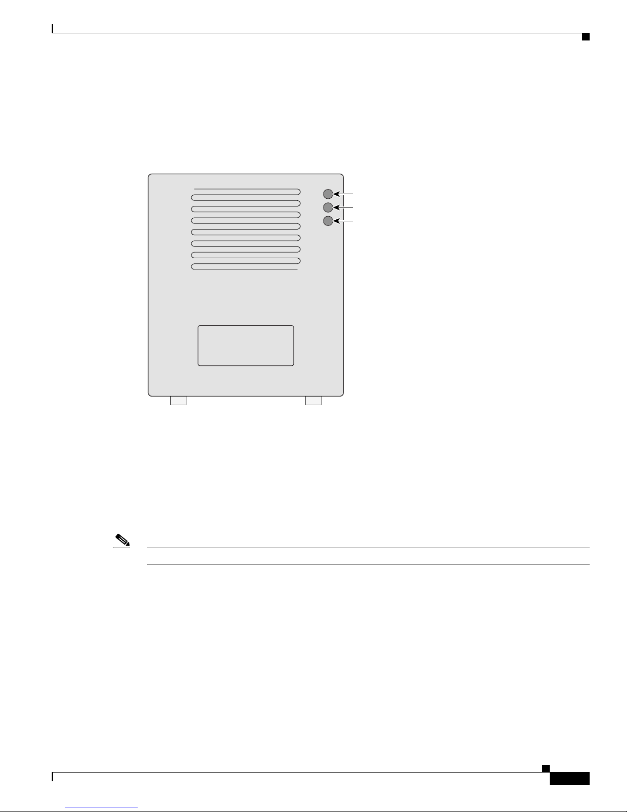
Indicators
The three indicators on top of the access point report Ethernet activity, association status, and radio
activity as shown in Figure 1-1.
Figure 1-1 Indicators on the 1200 Series Access Point
•
The Ethernet indic ator signals Ethernet traffic on the wired LAN. This indicator blinks green when
a packet is received or transmitted over the Ethernet infrastructure. The indicator blinks red when
the Ethernet cable is not connected.
• The association sta tus indic ato r sign als o pe ratio nal s tatus. Blinki ng gree n ind i cates t hat the acc ess
point is operating normally but is not associated with any wireless client devices. Steady green
indicates that the access point is associated with at least one wireless client device.
• The radio indicator blinks green to indicate radio traffic activity. The light is normally off, but it
blinks green whenever a packet is received or transmitted over th e access point radio.
Note The Radio and St at us in dica tor s a re u s ed f or both 2. 4- GHz a nd 5- GHz r a dio o pe rat ion.
Ethernet
Status
Radio
74046
1-6
Cisco Aironet 1200 Series Access Point Hardware Installation Guide
OL-2155-02
Chapter 1 Overview
Key Features
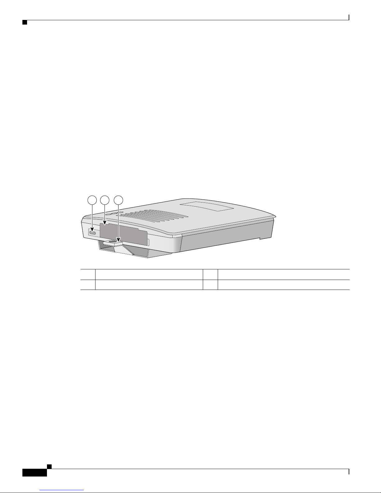
Security Lock Feature
The access point provides two methods of securing the access point to help prevent theft (see
Figure 1-2):
• Security hasp
• Security cable keyhole
The security hasp on the mounting bra cket enables you to lock the access point to the brac k e t to make it
more secure. When the access point is properly installed on the mounting bracket, the holes in th e
security hasps line up so you can install a pa dlock. Compatible padlocks are Master Lock models 120T
or 121T.
When using the security hasp with a lock, the access point is secured to the mounting bracket and the
mounting bracket sc rews alon g w ith th e 2. 4-G Hz radi o a cce ss cover ar e not ac cessib le.
The security cable keyhole allows you to secure the access point using a standard security cable, such as
the security cabl es us ed on l a ptop co mp uter s.
Figure 1-2 Access Point Security Points
1 Security cable keyhole 3 Se curi ty hasp f or padl ock
2 5-GHz module slot access cover
21 3
74344
1-7
Cisco Aironet 1200 Series Access Point Hardware Installation Guide
OL-2155-02
Chapter 1 Overview
Network Configuration Examples
Network Configuration Examples
This section describes the access point ’s role in three commo n wireless networ k configurati ons. The
access point’s default configurati on is as a root unit on a w ired LAN. The other two possi ble roles,
repeater unit and central unit in an all-wireless network, require specific changes to the default
configuration.
Note The following network configurati on examples ap ply to both 2.4 -GH z and 5-GHz wireless LA Ns.
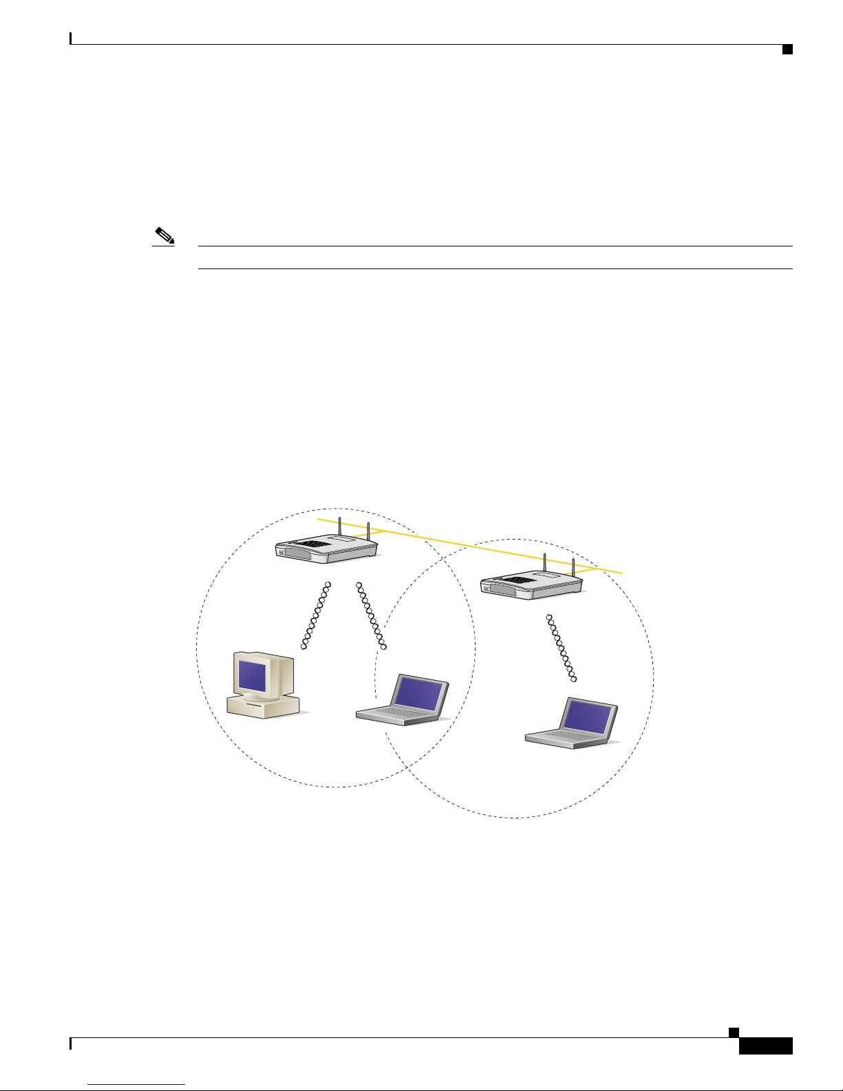
Root Unit on a Wired LAN
An access point connected directly to a wired LAN provides a connection point for wireless users. If
more than one access poi nt is connected to the LAN, users c an roam from one area of a fac ility to another
without losing thei r conn ect ion to t he ne twork. A s users move out o f range o f one a ccess poi nt, they
automatically con nect to the network (assoc iate) th rough anot her acces s point . The roami ng proce ss is
seamless and transparent to th e user. Figure 1-3 shows access points acting as root units on a wired LAN.
Figure 1-3 Access Points as Root Units on a Wired LAN
Access Point
(Root Unit)
Access Point
(Root Unit)
65999
Wired LAN
1-8
Cisco Aironet 1200 Series Access Point Hardware Installation Guide
OL-2155-02
Chapter 1 Overview
Network Configuration Examples
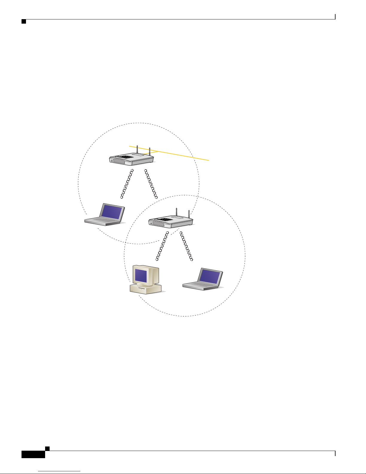
Repeater Unit That Extends Wireless Range
An access point can be configured as a stand alone repeater to extend the range of your infrastructure or
to overcome an obstacle that blocks radio communication. The repeater forwards traffic between
wireless users and the wired LAN by sending packets to ei ther an other repe ater or to an a ccess poi nt
connected to the wired LAN. The data is sent through the route that provides the greatest performance
for the client. Figure 1-4 shows an access point acting as a repeater.
Figure 1-4 Access Point as Repeater
Access Point
(Root Unit)
Access Point
(Repeater)
66000
Wired LAN
1-9
Cisco Aironet 1200 Series Access Point Hardware Installation Guide
OL-2155-02
Chapter 1 Overview
Network Configuration Examples
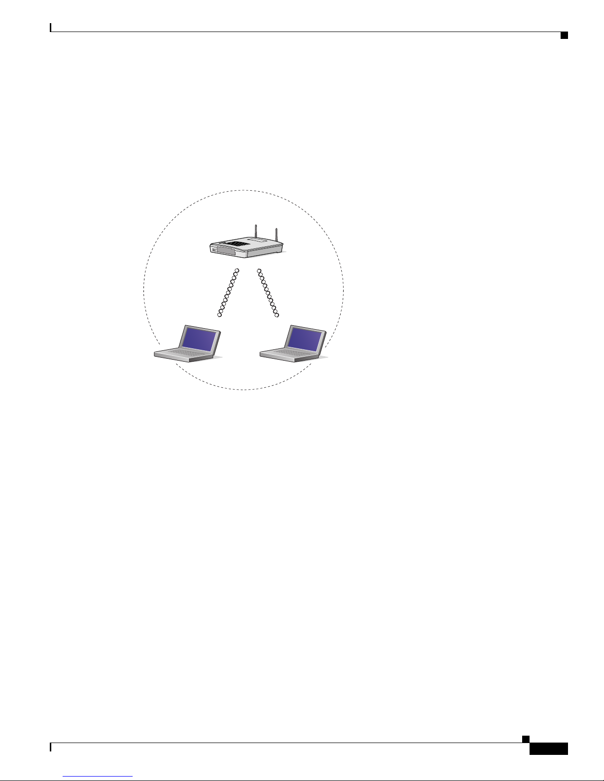
Central Unit in an All-Wireless Network
In an all-wireless network, an access point acts as a stand-alone root unit. The access point is not
attached to a wired LAN; it functions as a hub linking all stations together. The access point serves as
the focal point for communications, increasing the communication range of wireless users. Figure 1-5
shows an access point in an all-wireless network.
Figure 1-5 Access Point as Central Unit in All-Wireless Network
Access Point
(Root Unit)
65998

1-10
Cisco Aironet 1200 Series Access Point Hardware Installation Guide
OL-2155-02
Chapter 1 Overview
Access Point Specifications
Access Point Specifications
The access point specifications are listed in Table 1-1.
Table 1-1 Access Point Specifications
Category Access Point with 2.4-GHz Radio Access Point with 5-GHz Radio Module
Size 6.56 in. W x 7.23 in. D x 1.66 in. H
16.67 cm W x 1 8.36 cm D x 4 .22 cm H
With the 5-GHz antenna in the patch position:
6.56 in. W x 8.04 in. D x 2.21 in. H
16.67 cm W x 20.42 cm D x 5.61
Status Indicators Three indicators on t he top pa nel : E therne t t raffic, status, a nd ra dio tra ffic
Connectors Back panel (left to right): reverse-TNC antenna connector; power connector (for plug-in AC power
module); RJ-45 connector for 10BASE-T or 100BASE-T Ethernet connections; upside down RJ-45
connector for serial connections; reverse-TNC antenna connector.
Front Panel: Card Bus connector used for the 5-GHz radi o module .
Input Volta ge 48 VDC nominal. O pera ti onal up t o 60 V DC . Voltage higher than 60 VDC c an d am age the un it.
Input Current With 2.4 GHz radio:
125 mA (typical)
With 5-GHz radio:
165 mA (typical)
With 2.4-GHz and 5-GHz radios
225 mA (typical)
The access point is capable of drawing 380 mA depending upon the current radios and future radios
installed in the unit.
Operating Temperature Access point:
–4 to 131
o
F (–20 to 55oC)
1200 series power injector:
32 to 104
o
F (0 to 40oC)
Access point (with 2.4-G Hz and 5-G Hz radio) :
–4 to 122
o
F (–20 to 50oC)
1200 series power inje ctor :
32 to 104
o
F (0 to 40oC)
Storage Temperature –40 to 185
o
F (–40 to 85oC) –40 to 185oF (–40 to 85oC)
Weight Without mounting bracket:
1.6 lbs (0.73 kg) wi th 2 .4- GHz ra dio
module
Without mounting bracket:
1.87 lbs (0.85 kg) with 5-Gh z radio mo dule
1.97 lbs (0.89 kg) with 5-GHz radio module and
2.4-GHz radio
Power Output 100, 50, 30, 20, 5, or 1 mW
(Depending on t h e regul ato ry do mai n in
which the access point is installed)
40 mW (16 dBm)
20 mW (13 dBm)
10 mW (10 dBm)
5 mW (7 dBm)
Note These values are based on the FCC peak
measurement method as defined in
FCC 15.407 (A)( 4)
Frequency 2.400 to 2.497 G Hz
(Depending on t h e regul ato ry do mai n in
which the access point is installed)
UNII 1—5.15 to 5.25 GH
UNII 2—5.25 to 5.35 GHz
(Depending on the regulat ory doma in in whic h the
access point is installed)

1-11
Cisco Aironet 1200 Series Access Point Hardware Installation Guide
OL-2155-02
Chapter 1 Overview
Access Point Specifications
Range Indoor:
150 ft at 11 M bps
350 ft at 1 Mbps
Outdoor:
800 ft at 11 M bps
2000 ft at 1 M bp s
Indoor:
170 ft at 6 M bps
130 ft at 18 Mbps
60 ft at 54 M bps
Outdoor:
1000 ft at 6 Mbps
100 ft at 54 Mbps
Modulation Direct Sequence Spread Spectrum (DSSS) Orthogonal Frequency Division Multiplex (OFDM)
Data rates 1, 2, 5.5, and 11 Mbps 6, 9, 12, 18, 24, 36, 48, and 54 Mb ps
Antenna A diversity system with two reverse-TNC
connectors (Cisco antennas are sold
separately).
A diversity system consisting of two integrated
omnidirectional and two integrated di rection al
antennas.
Compliance The 1200 series access point complies with UL 2043 for products installed in a building’s
environmental air handling spaces, such as above suspended ceilings.
Caution The 12 00 se rie s power inje ctor s ar e n ot test ed t o UL 20 43 a nd sh ould n ot be plac ed i n a
building’s environmental air space, such as above suspended ceilings.
Note If you plan to mount the access point in environmental air space using a 5-GHz radio, Cisco
recommends that you mount the access point horizontally with its antennas pointing down.
Doing so results in the access point co mply ing with regula tory requ irement s for
environmental air space with the 5-GHz radio installed.
Safety Designed to meet:
• UL 1950 Third Edition
• CSA 22.2 No. 950- 95
• IEC 60950 Second Edition, inc luding
Amendments 1-4 with all deviations
• EN 60950 Second Edition, including
Amendments 1-4
Designed to meet:
• UL 1950 Third Edition
• CSA 22.2 No. 950-95
• IEC 60950 Second Edition, incl uding
Amendments 1-4 with all deviations
• EN 60950 Second Ed i tion, inc ludi ng
Amendments 1-4
Radio Approvals FCC Part 15.247
Canada RSS-139-1, R SS-21 0
Japan Telec 33B
EN 300.328
FCC Part 15.4 07
Canada RSS-210
Japan ARIB STD-T71
EN 301.893
Table 1-1 Access Point Specifications (continued)
Category Access Point with 2.4-GHz Radio Access Point with 5-GHz Radio Module

1-12
Cisco Aironet 1200 Series Access Point Hardware Installation Guide
OL-2155-02
Chapter 1 Overview
Access Point Specifications
EMI and Susceptibility FCC Part 15.107 and 15.109 Class B
ICES-003 Class B (C anad a)
EN 55022 B
AS/NZS 3548 Class B
VCCI Class B
EN 55024
EN 301.489-1
EN 301.489-17
RF Exposure OET- 65C
RSS-102
ANSI C95.1
Table 1-1 Access Point Specifications (continued)
Category Access Point with 2.4-GHz Radio Access Point with 5-GHz Radio Module

CHAPTER
2-1
Cisco Aironet 1200 Series Access Point Hardware Installation Guide
OL-2155-02
2
Installation
This chapter describes the setup of the access point and includes the following sections:
• Safety Informat ion, p ag e 2-2
• Warn i ngs, p ag e 2-3
• Installation Guidelines, page 2-4
• Unpacking the Access Po int, page 2-6
• Before Beginning the I nsta llat ion, pag e 2-7
• Installation Summary, page 2-8
• Connecting the 2.4-GHz Antennas, page 2-8
• Connecting the Ethernet and Power Cables, page 2-9

2-2
Cisco Aironet 1200 Series Access Point Hardware Installation Guide
OL-2155-02
Chapter 2 Installation
Safety Information
Safety Information
Follow the guidelines in this section to ensure proper operation and safe use of the access point.
FCC Safety Compliance Statement
The FCC, with its action in ET Doc ket 96-8, has adop ted a safe ty standard for human exposur e to RF
electromagnetic energy emitted by FCC-certified equipment. When used with approved Cisco Aironet
antennas, Cisco Aironet products meet the uncontrolled environmental limits found in OET-65 and ANSI
C95.1, 1991. Proper operation of this radio device according to the instructions in this publication results
in user exposure substantially below the FC C recommended limits.
General Safety Guidelines
• Do not touch or move the antenna while the unit is transmitting or receiving.
• Do not hold any component containing a radio such that the antenna is very close to or touching any
exposed parts of the body, especially the face or eyes, while transmitting.
• Do not operate the radio or attempt to transmit data unless the antenna is connected; otherwise, the
radio may be damaged.
• Use in specific environme nts :
–
The use of wireless devices in hazardous locations is limited to the constraints posed by the
local codes, th e national codes and the safety directors of such environments.
–
The use of wir eless d evices on airpl ane s is governed by the Fede ra l Aviation Administrat ion
(FAA).
–
The use of wireless devices in hospitals is restricted to the limits set forth by each hospital.
• Antenna use:
–
High-gain wall-mount or mast-mou nt antenna s are designe d to be professi onally in stalled.
Please contact your professional installer, VAR, or antenna manufacturer for proper installation
requirements.

2-3
Cisco Aironet 1200 Series Access Point Hardware Installation Guide
OL-2155-02
Chapter 2 Installation
Warnings
Warnings
Translated versions of the following safety warnings are provided in Appendix A , “Translated Safe ty
Warn ings. ”
Warning
In order to comply with FCC radio frequency (RF) exposure limits, dipole antennas should be located
at a minimum of 7.9 inches (20 cm) or more from the body of all persons.
Warning
Do not operate your wireless network device near unshielded blasting caps or in an explosive
environment unless the device has been modified to be especially qualified for such use.
Warning
Do not locate the antenna near overhead power lines or other electric light or power circuits, or
where it can come into contact with such circuits. When installing the antenna, take extreme care
not to come into contact with such circuits, as they may cause serious injury or death. For proper
installation and grounding of the antenna, please refer to national and local codes (e.g. U.S.:NFPA 70,
National Electrical Code, Article 810, in Canada: Canadian Electrical Code, Section 54).
Warning
Do not work on the system or connect or disconnect cables during periods of lightning activity.
Warning
Read the installation instructions before you connect the system to its power source.
Warning
This product relies on the building's installation for short-circuit (overcurrent) protection. Ensure that
a fuse or circuit breaker no larger than 120 VAC, 15A U.S. (240 VAC, 10A international) is used on the
phase conductors (all current-carrying conductors).

2-4
Cisco Aironet 1200 Series Access Point Hardware Installation Guide
OL-2155-02
Chapter 2 Installation
Installation Guidelines
Installation Guidelines
This section describes th ings to keep in mind w hen install ing your ac cess point. Sections in clude:
• Basic Guidelines
• Installation Above Suspended Ceilings
• Coverag e Optio ns
• Site Surveys
Basic Guidelines
Because the access point is a radio dev ice, it is susceptible to common causes of interference that can
reduce throughpu t a nd ra nge . Foll ow these b asic gu ide lin es t o ensu re the b es t pos sibl e perfo rm an ce:
• Install the acces s po int i n an a rea wher e lar g e st eel st ructu res s uch a s sh elving units , boo kcase s, an d
filing cabinets do no t ob struc t radi o sign als to a nd from the ac cess point .
• Install the access point away from microwave ovens. Microwave ovens operate on the same
frequency as the access point and can cause signal interference.
Installation Above Suspended Ceilings
The access point uses a me tal encl osure having adequat e fire resistan ce and low smoke-pr oducing
characteristics suitable for operation in a building’s env ironm ental air sp ace i n acco rdanc e wit h
Section 300-22(c) of the NE C, such as above suspende d ceilings. For mo unting inst ruction s refer to
Chapter 4, “Mo unting In structi ons.”
Caution The 1200 series power injectors are not tested to UL 2043 and should not be placed in a building ’s
enviro nmental air space, such as above suspended ceilings.
Note If you plan to mount the access point in environmental air space using a 5-GHz radio, Cisco recommends
that you mount the access point h orizonta lly with i ts antennas p ointing down. Doing so will result in the
access point complying with regulatory requirements for environmental air space with the 5-GHz radio
installed.
2-5
Cisco Aironet 1200 Series Access Point Hardware Installation Guide
OL-2155-02
Chapter 2 Installation
Installation Guidelines
Coverage Options
The network architecture options of wireless stations and access points provide for a variety of coverage
alternatives and flexibility. The network can be designed to provide a wide coverage area with minimal
overlap or a narrow coverage ar ea wit h heavy overla p. A na rrow coverage are a wi th h eavy overla p
improves network performance and pr otec ti on aga inst downtime if a c om ponent fails.
Note The following coverage options apply to both 2.4-GHz and 5-GHz wireless LANs.
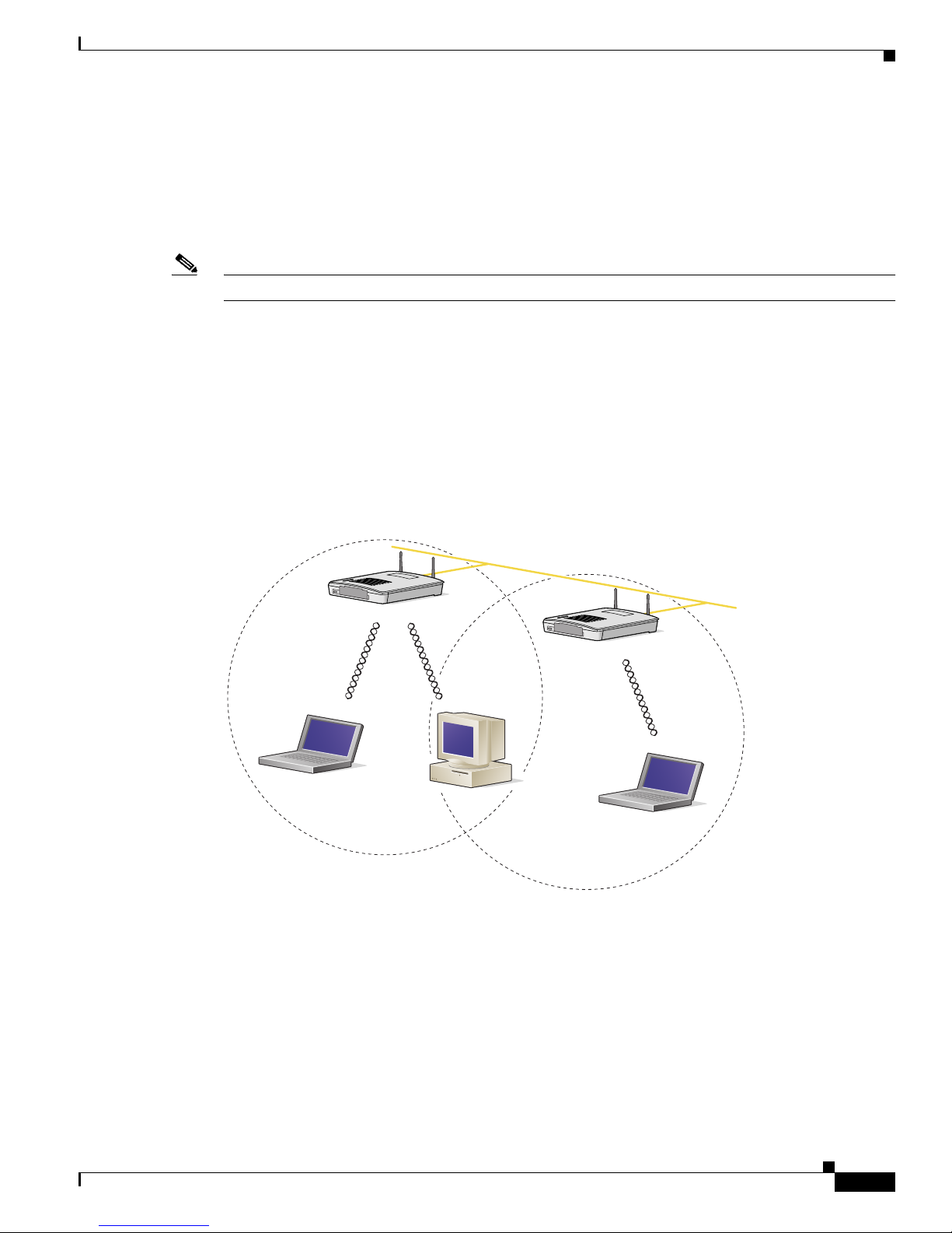
Minimal Overlap Coverage Option
By arranging the access points so that the overlap in a coverage area is minimized, a large area can be
covered with minimal cost (see Figure 2-1 ). The total bandwidth available to each wireless client device
depends on the amount of data ea ch mob ile stat ion ne eds to transfe r an d the num be r of stat ion s loca ted
in each cell. Seamless roaming is supported as a client device moves in and out of range of each access
point, thereby maintai ning a const ant con nection to the wi red LAN. Ea ch device in the ra dio network
must be configured with the same SSID to provide roaming capability.
Figure 2-1 Minimal Overlap Coverage Option
Heavy Overlap Coverage Option
By arranging the access points so the overlap in coverage area is nearly maximized, a large number of
mobile stations c an be supp orted in the sam e w irele ss infra stru ctur e. H owever, devices in overlapping
coverage areas on the same frequency det ect adjac ent cell tr affic and delay transmissi ons that woul d
cause collisions . This co nfigurat ion redu ce s the a ggregate ra dio s ystem throug hpu t . Heavy cell overlap
is not recommende d for m axi mum sy st em t hroug hpu t.
74001
Wired LAN

2-6
Cisco Aironet 1200 Series Access Point Hardware Installation Guide
OL-2155-02
Chapter 2 Installation
Unpacking the Access Point
Because of the redundancy in coverage overlap, network access is not lost if an access point fails. Upon
failure of the access point, the station automatically roams to an operational access point. With this
architecture, eac h device in t he R F net work mu st b e c onfigur ed w it h th e sam e SSID to p rovide the
roaming capability.
Site Surveys
Because of differen ces i n comp one nt co nfigurati on, pla cem ent , an d physi cal environmen t, every
network application is a unique instal lation. Before installing multiple access points, you should perform
a site survey to determine the optimum utilization of networking components and to maximize range,
coverage, and network p erfor ma nce.
When supporting d ual mode 2. 4-GH z a nd 5-G Hz opera ti on, yo u ma y have to pe rfo rm a sit e sur vey for
each of the operating frequenc ies.
Consider the following operating and environmental conditions when performing a site su rvey:
• Frequency—The radio coverage area for the 5-GHz radio is less than the coverage area for the
2.4-GHz radio.
• Single- and dual-band op eration—When suppo rting bo th sing l e- and dua l-b and a cce ss poi nts, you
should perform a site survey for each of th e operat ing freq uencie s.
• Data rates—Sensitivity and range are inversely proportional to data bit rate s. The maxi mum radi o
range is achiev ed at the lo west workable dat a rate. A decrease in rece iver th reshold sensiti vity occurs
as the radio data increases.
• Antenna type and p lacement—Proper antenna configuration is a critical factor in maximizing radio
range. As a general rule, range incre ases in prop ortion to antenn a height.
• Physical environment—C lear or open areas provide better radio range than closed or filled areas.
Also, the less cluttered the work environment, the greater the range.
• Obstructions—A physi cal obstr uctio n su ch a s m eta l sh elvi ng or a stee l p ill ar ca n hi nder
performance of wireless devices. Avoid locating the devices in a location where there is a metal
barrier between the sendi ng and rec eiving antennas.
• Building materials—Radio penetration is greatly influenced by the building material used in
construction. For example, drywall construction allows greater range than concrete blocks. Metal or
steel construction is a barri er to radio signa ls.
Unpacking the Access Point
Follow these steps to unpack the access point:
Step 1 Open the shipping container and carefully remove the contents.
Step 2 Return all pack ing mat erials t o the shi pping cont ai ner a nd save it.
Step 3 Ensure that all items listed in the “Package Contents” section are included in the shipment. Check each
item for damage . If a ny item i s dama ged or m issin g, no tif y y our aut hori zed Cisc o s ale s rep res enta tive.
 Loading...