

Page 1

Cisco Aironet 2.4 GHz and 5 GHz Dual-Band
Polarization-Diverse Directional Array Antenna
(AIR-ANT2566D4M-R)
This document describes the Cisco Aironet 2.4 GHz and 5 GHz Dual-Band Polarization-Diverse
Directional Array Antenna (AIR-ANT2566D4M-R), and provides electrical specifications and
mounting instructions.
The AIR-ANT2566D4M-R antenna is a four-port polarization-diverse array that operates over the
2.4 GHz and 5 GHz Wi-Fi bands. It ships with an articulating mount for use on flat surfaces and masts,
and is adjustable in both horizontal and vertical planes. The radome can be painted using commonly
available non-conductive spray paints, such as Krylon or Rust-Oleum.
The antenna is designed for use in indoor and outdoor environments with an approved Cisco Aironet
access point that requires four dual-band antennas.
The following information is provided in this document:
• Technical Specifications, page 2
• Azimuth and Elevation Radiation Patterns, page 3
• Safety Precautions, page 4
• Installation Notes, page 5
• Contents of the Antenna and Bracket Kit, page 6
• Dimensions of the Antenna and Brackets, page 7
• Installing the Antenna, page 10
• Obtaining Documentation and Submitting a Service Request, page 21
Cisco Systems, Inc.
www.cisco.com
Page 2
Technical Specifications
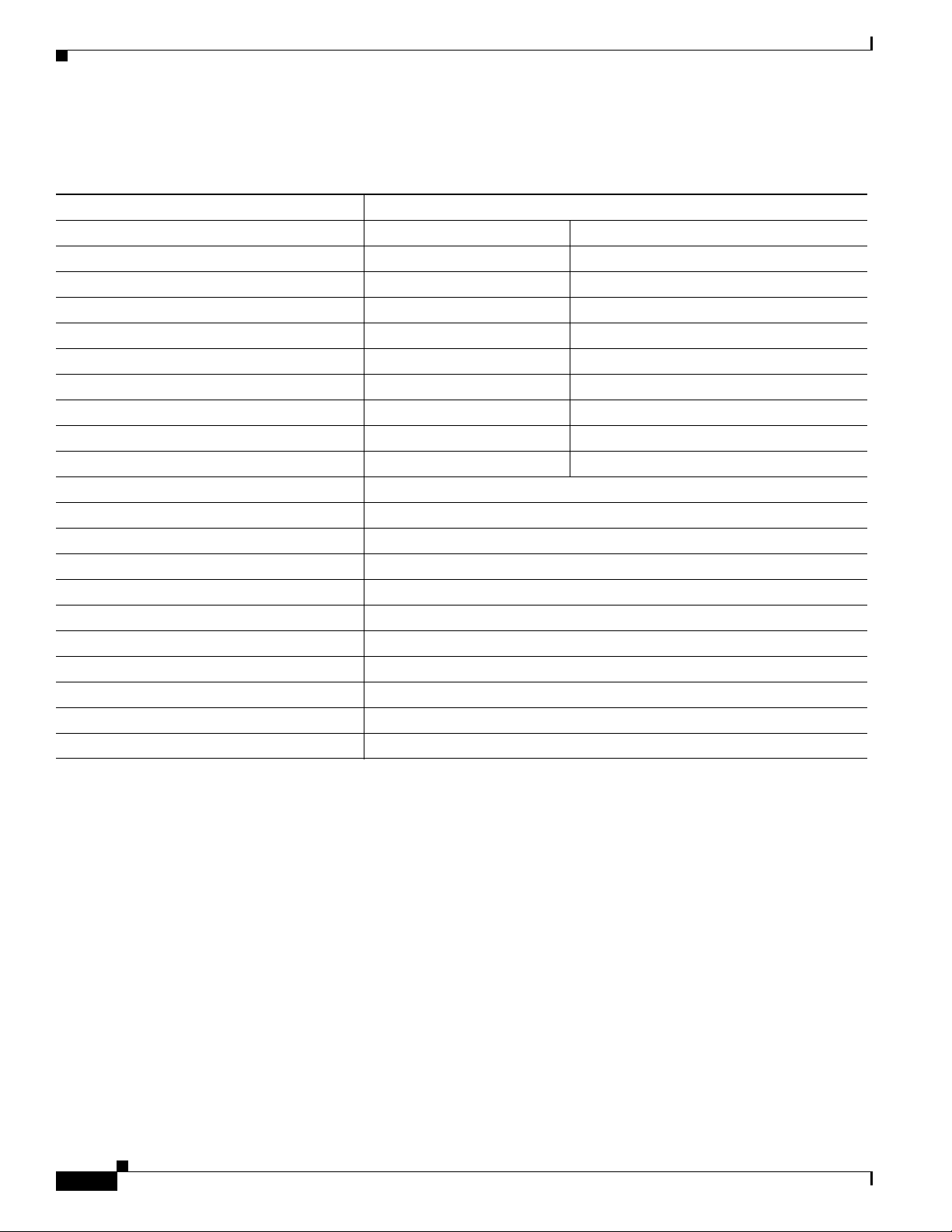
Technical Specifications
Antenna Type Dual-Band Polarization-Diverse Directional Array
Operating Frequency Ranges 2.4–2.5 GHz 5.15–5.925 GHz
Nominal Input Impedance 50 Ohms 50 Ohms
Voltage Standing Wave Ratio (VSWR) 2:1 2:1
Peak Gain 6 dBi 6 dBi
Polarization (Ports A & C) Vertical Vertical
Polarization (Ports B & D) Horizontal Horizontal
Nominal Elevation Plane 3-dB Beamwidth 65° 60°
Nominal Azimuth Plane 3-dB Beamwidth 65° 55°
Front-to-Back Ratio > 12 dB > 20 dB
Port-to-Port Isolation > 30 dB > 30 dB
> or = to 30º Elevation Peak Gain 3 dBi
Connector Type RP-TNC (with coupling ring)
Cable Length 3 ft
Length 10 in. (25.4 cm)
Width 10 in. (25.4 cm)
Height 1.61 in. (4.1 cm)
Weight 2.5 lbs. (1.13 kg)
Water/Foreign Body Ingress IP-67
Operational Wind 100 MPH
Operating Temperature Range -40° C to 70° C
Storage Temperature Range -40° C to 85° C
Cisco Aironet 2.4 GHz and 5 GHz Dual-Band Polarization-Diverse Directional Array Antenna (AIR-ANT2566D4M-R)
2
Page 3
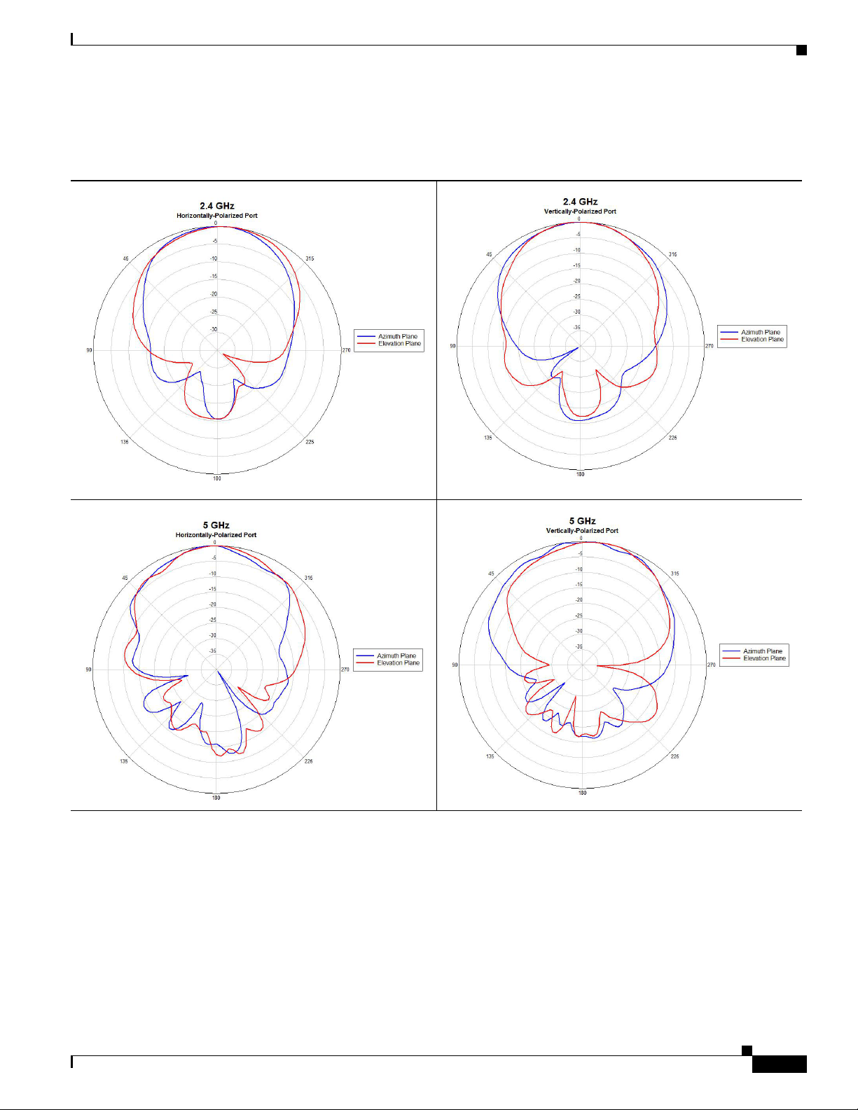
Azimuth and Elevation Radiation Patterns
Azimuth and Elevation Radiation Patterns
Cisco Aironet 2.4 GHz and 5 GHz Dual-Band Polarization-Diverse Directional Array Antenna (AIR-ANT2566D4M-R)
3
Page 4
Safety Precautions
Safety Precautions
Warning
Installation of this antenna near power lines is dangerous. For your safety, follow the installation
directions.
Each year, hundreds of people are killed or injured when attempting to install an antenna. In many of
these cases, the victim was aware of the danger of electrocution, but did not take adequate steps to avoid
the hazard.
For your safety, and to help you achieve a good installation, read and follow these safety precautions.
They may save your life!
• If you are installing an antenna for the first time, for your own safety as well as that of others, seek
professional assistance. Your Cisco sales representative can explain which mounting method to use
for the size and type of antenna you are about to install.
• Select your installation site with safety as well as performance in mind. Remember that electric
power lines and phone lines look alike. For your safety, assume that any overhead line can kill you.
• Call your electric power company. Tell them your plans and ask them to come and look at your
proposed installation. This is a small inconvenience considering your life is at stake.
• Plan your installation carefully and completely before you begin. Successful raising of a mast or
tower is largely a matter of coordination. Each person should be assigned a specific task, and should
know what to do and when to do it. One person should be in charge of the operation to issue
instructions and watch for signs of trouble.
• When installing your antenna, remember:
–
Do not use a metal ladder.
–
Do not work on a wet or windy day.
–
Do dress properly—shoes with rubber soles and heels, rubber gloves, long sleeved shirt or
jacket.
• If the assembly starts to drop, get away from it and let it fall. Remember, the antenna, mast, cable,
and metal guy wires are all excellent conductors of electrical current. Even the slightest touch of any
of these parts to a power line completes an electrical path through the antenna and the installer: You !
• If any part of the antenna system should come in contact with a power line, don’t touch it or try to
remove it yourself. Call your local power company. They will remove it safely.
• If an accident occurs with the power lines, call for qualified emergency help immediately.
For a listing of all the warning statements and their translations, see Translated Safety Warnings for
Cisco Aironet Access Points at:
http://www.cisco.com/c/en/us/td/docs/wireless/access_point/warnings/reference/guide/ap_warn1.html
Cisco Aironet 2.4 GHz and 5 GHz Dual-Band Polarization-Diverse Directional Array Antenna (AIR-ANT2566D4M-R)
4
Page 5
Installation Notes
Antennas transmit and receive radio signals that are susceptible to RF obstructions and common sources
of interference that can reduce throughput and the range of the device to which they are connected.
Follow these guidelines to ensure the best possible performance:
• Install the antenna vertically and mount it with the cables pointing towards the ground.
• Keep the antenna away from metal obstructions such as heating and air-conditioning ducts, large
ceiling trusses, building superstructures, and major power cabling runs. If necessary, use a rigid
conduit to lower the antenna away from these obstructions.
• The density of the materials used in a building’s construction determines the number of walls the
signal can pass through and still maintain adequate signal strength. Consider the following before
choosing the location for your antenna:
–
Signals penetrate paper and vinyl walls with little change to signal strength.
–
Signals penetrate only one or two solid and precast concrete walls without degrading signal
strength.
–
Signals penetrate three or four concrete and wood block walls without degrading signal
strength.
–
Signals penetrate five or six walls constructed of drywall or wood without degrading signal
strength.
–
Signals are likely to reflect off a thick metal wall and may not penetrate it at all.
Installation Notes
–
Signals are likely to reflect off a chain link fence or wire mesh spaced between 1 and 1 1/2 inch.
(2.5 and 3.8 cm). The fence acts as a harmonic reflector that blocks the signal.
• Install the antenna away from microwave ovens and 2-GHz cordless phones. These products can
cause signal interference because they operate in the same frequency range as the device to which
your antenna is connected.
Cisco Aironet 2.4 GHz and 5 GHz Dual-Band Polarization-Diverse Directional Array Antenna (AIR-ANT2566D4M-R)
5
Page 6
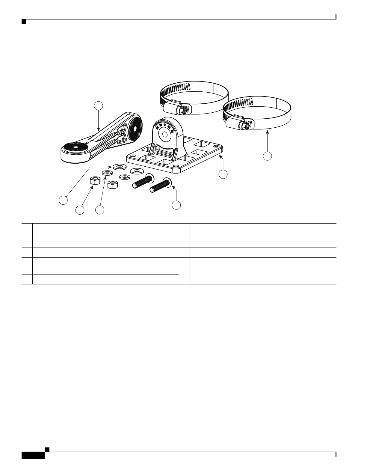
Contents of the Antenna and Bracket Kit
Contents of the Antenna and Bracket Kit
Figure 1 Contents of the Antenna Bracket Kit
2
2X
7
1
4
2X
2X
2X
6
5
1 One of two articulating mount flanges required for the
2X
3
5 1/4-inch split-lock washers. Two are included in the kit.
installation. The other flange comes attached to the back
of the antenna.
2 Articulating mount arm. 6 1/4-20 Hex nuts. Two are included in the kit.
3 1/4 20 x 1.25-inch stainless steel screws. Two are
included in the kit.
7 one of two worm-gear type hose clamps. Each has a range
of 50–135mm
4 1/4 inch flat washers. Two are included in the kit.
353895
Cisco Aironet 2.4 GHz and 5 GHz Dual-Band Polarization-Diverse Directional Array Antenna (AIR-ANT2566D4M-R)
6
Page 7
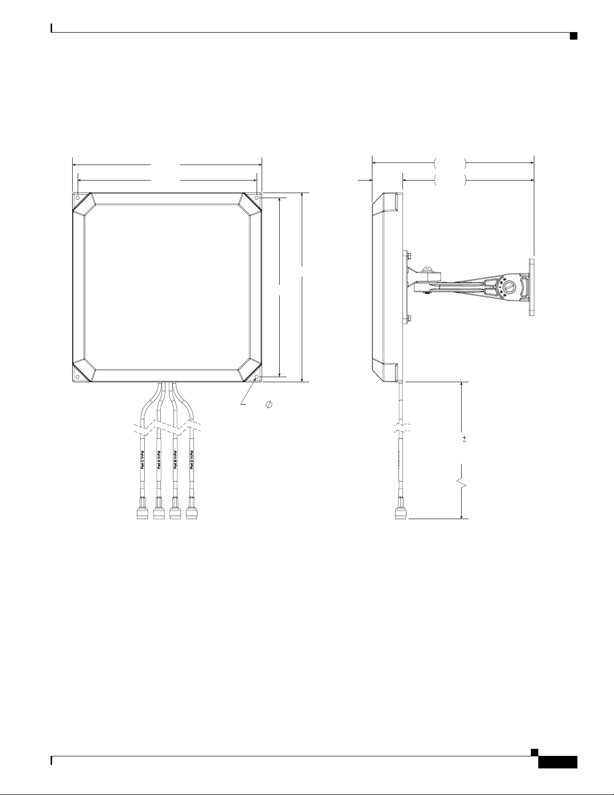
240.0
240.0
254.0
254.0
4X
4.50
THRU ALL
41.0
36"
1"
FROM BOTTOM
EDGE OF RADOME
217.0
176.0
Dimensions of the Antenna and Brackets
The dimensions noted in the following illustrations are all in mm, unless noted otherwise.
Figure 2 Dimensions of the Antenna with Brackets and Cables
Dimensions of the Antenna and Brackets
Cisco Aironet 2.4 GHz and 5 GHz Dual-Band Polarization-Diverse Directional Array Antenna (AIR-ANT2566D4M-R)
7
Page 8

Dimensions of the Antenna and Brackets
Figure 3 Locations of Screw Holes and Pressure Vent at the Back of the Antenna
62.0
C
L
83.1
4X M4x0.7 THREADED
INSERT
C
L
PRESSURE RELEASE
VENT
353894
Cisco Aironet 2.4 GHz and 5 GHz Dual-Band Polarization-Diverse Directional Array Antenna (AIR-ANT2566D4M-R)
8
Page 9

353897
4X
4.50
62.0
83.1
Figure 4 Locations of the Screw Holes on the Articulating Mount Flange
Dimensions of the Antenna and Brackets
Cisco Aironet 2.4 GHz and 5 GHz Dual-Band Polarization-Diverse Directional Array Antenna (AIR-ANT2566D4M-R)
9
Page 10

Installing the Antenna
Installing the Antenna
You can install the antenna on a wall or ceiling (must be a flat surface), or on a pole with a minimum
diameter of 2 inches (5.08 cm) and a maximum diameter of 5 inches (12.7 cm). The antenna and one
mounting flange are connected together when shipped.
To install the antenna:
Step 1 Decide on a mounting location. See the “Deciding on a Mounting Location” section on page 10.
Step 2 Ensure that you have the requisite tools and fasteners ready. See the “Tools and Equipment Required”
section on page 11.
Step 3 Proceed with mounting the antenna. When mounting the antenna, assemble the bracket hardware,
connect the antenna and bracket to the mounting surface, and adjust the antenna orientation.
The mounting options available are:
a. Mounting on a Wall or Ceiling, page 12.
b. Mounting on a Pole or Mast, page 17.
c. Flush Mounting on a Wall Without Mount Brackets, page 19.
Step 4 (Optional) Paint the antenna. See the “Painting the Antenna” section on page 21.
Deciding on a Mounting Location
The antenna should be mounted clear of any obstructions to the side or front of the enclosure, which
contains the radiating elements. Keep in mind that this antenna should be aimed at the intended coverage
area. Therefore, you should mount the antenna such that the desired mechanical tilt is achieved. If
possible, mount the antenna near the access point so that you can use the shortest possible connecting
cables.
Caution For outdoor installations, install the antenna with cables exiting downward. This will help prevent water
from accumulating around the cable exit points.
10
Cisco Aironet 2.4 GHz and 5 GHz Dual-Band Polarization-Diverse Directional Array Antenna (AIR-ANT2566D4M-R)
Page 11

Tools and Equipment Required
Installing the Antenna
Warning
Warning
The fasteners and the mounting surface should be capable of maintaining a minimum pullout force of
150 pounds (68 kg) to support the weight of the antenna and bracket along with the potential wind
loading on the antenna.
The pole or mast must be rigid enough to hold the weight of the antenna along with the associated
forces produced by wind loads. Also, the pole or mast must be structurally strong enough to withstand
the clamping force of the hose clamps.
Before you start with mounting the antenna, go through the mounting procedure for each kind of
installation and ensure that you have all tools and fasteners mentioned therein ready. The following is a
general list of fasteners and tools which are not included in the antenna and brackets kit.
• To loosen and tighten the adjustment bolts on the brackets, you need a flat-blade screwdriver.
• To mount the antenna on a wall or ceiling, you need four mounting 4 mm or #8 screws or bolts and
wall anchors.
• To mount the antenna on a pole or mast, you will need either or both of these supplies:
–
Slotted screwdriver to tighten the screws on the hose clamps
–
A 5/16 inch (8mm) socket or box wrench
• You may also need the following tools and equipment, which are not provided as part of the kit:
–
A drill and drill bit
–
A pencil
–
A small mallet or hammer, to hammer
–
A Phillips screwdriver
Cisco Aironet 2.4 GHz and 5 GHz Dual-Band Polarization-Diverse Directional Array Antenna (AIR-ANT2566D4M-R)
11
Page 12

Installing the Antenna
Mounting on a Wall or Ceiling
Note The fasteners and mounting surface should be capable of maintaining a minimum pullout force of 150
pounds (68 kg) to support the weight of the antenna along with the potential wind loading on the antenna.
Step 1 Determine the mounting location for the antenna.
Step 2 Attach the free articulating mount flange to the wall or ceiling using four 4 mm or #8 screws and
fasteners, through the holes on the bracket.
One of the two required articulating mount flange brackets come attached to the back of the antenna (see
Figure 1). The other flange bracket, included in the kit, is the one used in this step.
Step 3 Assemble the bracket hardware, as shown in Figure 5. Use a flat blade screwdriver to tighten the 1/4 20
x 1.25" screws on the brackets.
Step 4 Orient the antenna correctly (note the arrow on the back of the antenna that indicates the top of the
antenna). Use a flat-blade screwdriver to loosen or tighten the fasteners at the azimuth and elevationadjustment pivots.
Step 5 Adjust the azimuth (side-to-side position) and elevation (up-and-down position) of the antenna. Loosen
the adjustment pivot bolts slightly to allow for adjustment.
The azimuth angle can be adjusted ±90 degrees (Figure 7) and elevation can be adjusted ±55 degrees
(Figure 8).
Use the azimuth and elevation markings on the articulating mounting arm and the flange brackets as a
guide. See Figure 6.
Step 6 After adjusting the antenna position, tighten the pivot bolts. Tighten all the bolts to not more than
30 lbf.in. (3.4 Nm).
Step 7 Connect the antenna cables to the access point. The antenna ports are labeled A through D. Connect the
antenna port A to connector A on the access point, antenna port B to connector B on the access point,
and so on.
For the recommended cable type, see the “Recommended Cable” section on page 21.
12
Cisco Aironet 2.4 GHz and 5 GHz Dual-Band Polarization-Diverse Directional Array Antenna (AIR-ANT2566D4M-R)
Page 13

353896
4
2
3
1
Figure 5 Exploded View of Antenna and Bracket Hardware Assembly
Installing the Antenna
1 The articulating mount flange bracket that comes
attached to the back of the antenna.
2 The azimuth adjustment pivot.
Here, a 1/4 20 x 1.25-inch stainless steel screw, a 1/4-inch
split-lock washer, a 1/4-inch flat washer, and a 1/4-20
Hex nut (in that order) fasten the articulating mount arm
to the flange bracket at the back of the antenna.
3 The end of the articulating mount arm, which attaches to
the flange bracket fixed to the wall or ceiling.
4 The elevation adjustment pivot.
Here, a 1/4 20 x 1.25-inch stainless steel screw, a 1/4-inch
split-lock washer, a 1/4-inch flat washer, and a 1/4-20
Hex nut (in that order) fasten the articulating mount arm
to the flange bracket fixed to the wall or ceiling.
Cisco Aironet 2.4 GHz and 5 GHz Dual-Band Polarization-Diverse Directional Array Antenna (AIR-ANT2566D4M-R)
13
Page 14

Installing the Antenna
353898
ANGULAR DETENTS
EVERY 5
ANGULAR MARKINGS
EVERY 5
, LABELS AT
30
& 60
Figure 6 Close-Up View of the Azimuth and Elevation-Adjustment Pivots
14
Cisco Aironet 2.4 GHz and 5 GHz Dual-Band Polarization-Diverse Directional Array Antenna (AIR-ANT2566D4M-R)
Page 15

Figure 7 Azimuth Adjustment
90°
ADJUSTMENT
Installing the Antenna
MAST
AZIMUTH ADJUSTMENT
353901
Cisco Aironet 2.4 GHz and 5 GHz Dual-Band Polarization-Diverse Directional Array Antenna (AIR-ANT2566D4M-R)
15
Page 16

Installing the Antenna
353899
55°
ADJUSTMENT
ELEVATION ADJUSTMENT
MAST
Figure 8 Elevation Adjustment
16
Cisco Aironet 2.4 GHz and 5 GHz Dual-Band Polarization-Diverse Directional Array Antenna (AIR-ANT2566D4M-R)
Page 17

Mounting on a Pole or Mast
Note The pole or mast must be rigid enough to hold the weight of an antenna along with the associated forces
produced by wind loads. In addition, the mast must be structurally strong enough to withstand the
clamping force of the hose clamps.
Step 1 Determine the mounting location for the antenna on the pole or mast.
Step 2 Position and mount the mounting flange bracket on to the pole or mast using the hose clamps provided
in the kit. The hose clamps should pass through the slots on the free mounting flange bracket.
One of the two required articulating mount flange brackets come attached to the back of the antenna (see
Figure 1). The other flange bracket, included in the kit, is the one used in this step.
Step 3 Tighten the hose clamps only to the extent that they can hold the flange bracket and the antenna in place
until the antenna is positioned at its final position. Use a slotted screwdriver to tighten the screws on the
hose clamps.
Step 4 Assemble the antenna and bracket to the flange bracket. See Figure 5.
Step 5 Position the antenna, mounting bracket, and hose clamps on the mast. See Figure 9 for reference.
Step 6 Tighten the hose clamps until the antenna is fully secure on the mast. Ensure that the antenna cannot
rotate about the mast.
Step 7 After the antenna is secured on the mast, adjust the azimuth (side-to-side position) and elevation
(up-and-down position) of the antenna. Loosen the adjustment pivot bolts slightly to allow for
adjustment.
Installing the Antenna
Azimuth angle can be adjusted ±90 degrees (Figure 7) and elevation can be adjusted ±55 degrees
(Figure 8).
You can use the azimuth and elevation markings on the articulating mounting arm and the flange brackets
as a guide. See Figure 6.
Step 8 After you adjust the antenna position, tighten the adjustment bolts. Tighten all the bolts to not more than
30 lbf.in. (3.4 Nm).
Step 9 Connect the antenna cables to the access point. The antenna ports are labeled A through D. Connect the
antenna port A to connector A on the access point, antenna port B to connector B on the access point,
and so on.
For the recommended cable type, see the “Recommended Cable” section on page 21.
Cisco Aironet 2.4 GHz and 5 GHz Dual-Band Polarization-Diverse Directional Array Antenna (AIR-ANT2566D4M-R)
17
Page 18

Installing the Antenna
Figure 9 Antenna Bracket Hose Clamp Assembly for Pole Mounting
1
2
3
4
353900
5
1 Articulating mount flange attached to the back of the
antenna.
4 Worm-gear-type hose clamp (50–135mm) for mounting
the assembly on a pole or mast.
2 Articulating mount arm. 5 Cables connecting the antenna to an access point.
3 Articulating mount flange that is fastened to the pole or
mast using hose clamps.
18
Cisco Aironet 2.4 GHz and 5 GHz Dual-Band Polarization-Diverse Directional Array Antenna (AIR-ANT2566D4M-R)
Page 19

Flush Mounting on a Wall Without Mount Brackets
You can flush mount the antenna on a wall. For this, you will need to discard the articulating mount
flange brackets from the installation.
Note The following procedure describes how to mount the antenna on a drywall. If you intend to install your
antenna on another surface other than a drywall, the following procedure may vary slightly and you
should procure the necessary hardware.
Step 1 Remove the articulating mount flange bracket that comes attached to the back of the antenna.
Step 2 Determine the location where you will mount the antenna.
Step 3 Use the antenna as a template to mark the location of the four mounting holes. See Figure 10 for the
locations of the holes.
Step 4 Using a drill and #29 drill bit, drill four holes at the locations you have marked in Step 3. For drywall
installations a #29 (0.136 inch or 45 mm) drill bit is enough. Other surfaces may require a different size.
Step 5 Insert 8-inch plastic wall anchors into each hole.
Step 6 Using a mallet or small hammer, properly seat the plastic anchors into the wall.
Step 7 Align the antenna's mounting holes with the anchors.
Installing the Antenna
Step 8 Insert an 8 x 1¼-inch screw, through each mounting hole and into its anchor.
Step 9 Tighten the screws using a Phillips screwdriver. Do not overtighten.
Step 10 Connect the antenna cables to the access point. The antenna ports are labeled A through D. Connect the
antenna port A to connector A on the access point, antenna port B to connector B on the access point,
and so on.
For the recommended cable type, see the “Recommended Cable” section on page 21.
Cisco Aironet 2.4 GHz and 5 GHz Dual-Band Polarization-Diverse Directional Array Antenna (AIR-ANT2566D4M-R)
19
Page 20

Installing the Antenna
Figure 10 Back of the Antenna with Flush Mounting Screw-Holes Locations
1
2
1
3
354039
1 Screw holes for flush mounting on a wall. Each hole takes
an 8 x 1¼-inch screw.
See Figure 2 for the distances between these holes.
2 Spot where the preinstalled articulating flange mount was
removed from.
Cisco Aironet 2.4 GHz and 5 GHz Dual-Band Polarization-Diverse Directional Array Antenna (AIR-ANT2566D4M-R)
20
3 Pressure release vent.
Page 21

Recommended Cable
This antenna comes with four 3-ft long cables with RP-TNC connectors. If you need a longer cable
reach, use AIR-CAB005LL-R= to extend the length by an additional 5 feet.
Note A coaxial cable loses efficiency as the frequency increases, resulting in signal loss. The cable should be
kept as short as possible because cable length also determines the amount of signal loss (the longer the
cable, the greater the loss).
Painting the Antenna
Painting the antenna and the bracket does not affect its performance if you use standard exterior-grade,
oil-based, or latex paint. Do not use metallic or metallic-flake paints, which will degrade antenna
performance.
Note Before painting the antenna, cover the pressure-release vent on the rear, lower-left of the antenna with
masking tape to prevent clogging. Ensure that you remove the tape afterwards.
Obtaining Documentation and Submitting a Service Request
We recommend that you use Krylon Fusion for Plastic or Rust-Oleum for Plastic (which might require
a primer coat). For best results, follow the surface preparation suggestions from the paint manufacturer.
Obtaining Documentation and Submitting a Service Request
For information on obtaining documentation, using the Cisco Bug Search Tool (BST), submitting a
service request, and gathering additional information, see What’s New in Cisco Product Documentation.
To receive new and revised Cisco technical content directly to your desktop, you can subscribe to
the What’s New in Cisco Product Documentation RSS feed. The RSS feeds are a free service.
Cisco and the Cisco logo are trademarks or registered trademarks of Cisco and/or its affiliates in the U.S. and other countries. To view a list of
Cisco trademarks, go to this URL: www.cisco.com/go/trademarks. Third-party trademarks mentioned are the property of their respective owners.
The use of the word partner does not imply a partnership relationship between Cisco and any other company. (1110R)
© 2015 - 2016 Cisco Systems, Inc. All rights reserved.
Cisco Aironet 2.4 GHz and 5 GHz Dual-Band Polarization-Diverse Directional Array Antenna (AIR-ANT2566D4M-R)
21
Page 22

22
Cisco Aironet 2.4 GHz and 5 GHz Dual-Band Polarization-Diverse Directional Array Antenna (AIR-ANT2566D4M-R)
 Loading...