

Page 1

Cisco IOS
IP
Configuration Guide
Release 12.2
Corporate Headquarters
Cisco Systems, Inc.
170 West Tasman Drive
San Jose, CA 95134-1706
USA
http://www.cisco.com
Tel:
408 526-4000
800 553-NETS (6387)
Fax: 408 526-4100
Customer Order Number: DOC-7811741=
Text Part Number: 78-11741-02
Page 2

THE SPECIFICATIONS AND INFORMATION REGARDING THE PRODUCTS IN THIS MANUAL ARE SUBJECT TO CHANGE WITHOUT
NOTICE. ALL STATEMENTS, INFORMATION, AND RECOMMENDATIONS IN THIS MANUAL ARE BELIEVED TO BE ACCURATE BUT ARE
PRESENTED WITHOUT WARRANTY OF ANY KIND, EXPRESS OR IMPLIED. USERS MUST TAKE FULL RESPONSIBILITY FOR THEIR
APPLICATION OF ANY PRODUCTS.
THE SOFTWARE LICENSE AND LIMITED WARRANTY FOR THE ACCOMPANYING PRODUCT ARE SET FORTH IN THE INFORMATION
PACKET THAT SHIPPED WITH THE PRODUCT AND ARE INCORPORATED HEREIN BY THIS REFERENCE. IF YOU ARE UNABLE TO
LOCATE THE SOFTWARE LICENSE OR LIMITED WARRANTY, CONTACT YOUR CISCO REPRESENTATIVE FOR A COPY.
The Cisco implementation of TCP header compression is an adaptation of a program developed by the University of California, Berkeley (UCB) as part of
UCB’s public domain version of the UNIX operating system. All rights reserved. Copyright © 1981, Regents of the University of California.
NOTWITHSTANDING ANY OTHER WARRANTY HEREIN, ALL DOCUMENT FILES AND SOFTWARE OF THESE SUPPLIERS ARE PROVIDED
“AS IS” WITH ALL FAULTS. CISCO AND THE ABOVE-NAMED SUPPLIERS DISCLAIM ALL WARRANTIES, EXPRESSED OR IMPLIED,
INCLUDING, WITHOUT LIMITATION, THOSE OF MERCHANTABILITY, FITNESS FOR A PARTICULAR PURPOSE AND
NONINFRINGEMENT OR ARISING FROM A COURSE OF DEALING, USAGE, OR TRADE PRACTICE.
IN NO EVENT SHALL CISCO OR ITS SUPPLIERS BE LIABLE FOR ANY INDIRECT, SPECIAL, CONSEQUENTIAL, OR INCIDENTAL
DAMAGES, INCLUDING, WITHOUT LIMITATION, LOST PROFITS OR LOSS OR DAMAGE TO DATA ARISING OUT OF THE USE OR
INABILITY TO USE THIS MANUAL, EVEN IF CISCO OR ITS SUPPLIERS HAVE BEEN ADVISED OF THE POSSIBILITY OF SUCH DAMAGES.
AccessPath, AtmDirector, Browse with Me, CCDA, CCDE, CCDP, CCIE, CCNA, CCNP, CCSI, CD-PAC, CiscoLink, the Cisco NetWorks logo, the Cisco
Powered Network logo, Cisco Systems Networking Academy, the Cisco Systems Networking Academy logo, Fast Step, Follow Me Browsing, FormShare,
FrameShare, GigaStack, IGX, Internet Quotient, IP/VC, iQ Breakthrough, iQ Expertise, iQ FastTrack, the iQ Logo, iQ Net Readiness Scorecard, MGX,
the Networkers logo, Packet, PIX, RateMUX, ScriptBuilder, ScriptShare, SlideCast, SMARTnet, TransPath, Unity, Voice LAN, Wavelength Router, and
WebViewer are trademarks of Cisco Systems, Inc.; Changing the Way We Work, Live, Play, and Learn, Discover All That’s Possible, and Empowering
the Internet Generation, are service marks of Cisco Systems, Inc.; and Aironet, ASIST, BPX, Catalyst, Cisco, the Cisco Certified Internetwork Expert logo,
Cisco IOS, the Cisco IOS logo, Cisco Systems, Cisco Systems Capital, the Cisco Systems logo, Enterprise/Solver, EtherChannel, EtherSwitch, FastHub,
FastSwitch, IOS, IP/TV, LightStream, MICA, Network Registrar, Post-Routing, Pre-Routing, Registrar, StrataView Plus, Stratm, SwitchProbe, TeleRouter,
and VCO are registered trademarks of Cisco Systems, Inc. or its affiliates in the U.S. and certain other countries.
All other brands, names, or trademarks mentioned in this document or Web site are the property of their respective owners. The use of the word partner
does not imply a partnership relationship between Cisco and any other company. (0102R)
Cisco IOS IP Configuration Guide
Copyright © 2001–2006, Cisco Systems, Inc.
All rights reserved.
Page 3

About Cisco IOS Software Documentation xxix
Documentation Objectives xxix
Audience xxix
Documentation Organization xxix
Documentation Modules xxix
Master Indexes xxxii
Supporting Documents and Resources xxxii
New and Changed Information xxxiii
Document Conventions xxxiii
Obtaining Documentation xxxv
World Wide Web xxxv
Documentation CD-ROM xxxv
Ordering Documentation xxxv
Documentation Feedback xxxv
Obtaining Technical Assistance xxxvi
Cisco.com xxxvi
Technical Assistance Center xxxvi
Contacting TAC by Using the Cisco TAC Website xxxvi
Contacting TAC by Telephone xxxvii
CONTENTS
Using Cisco IOS Software xxxix
Understanding Command Modes xxxix
Getting Help xl
Example: How to Find Command Options xli
Using the no and default Forms of Commands xliii
Saving Configuration Changes xliv
Filtering Output from the show and more Commands xliv
Identifying Supported Platforms xlv
Using Feature Navigator xlv
Using Software Release Notes xlv
IP Overview IPC-1
IP Addressing and Services IPC-1
IP Routing Protocols IPC-2
Cisco IOS IP Configuration Guide
iii
Page 4

Contents
Determining a Routing Process IPC-2
Interior and Exterior Gateway Protocols IPC-2
Interior Gateway Protocols IPC-3
Exterior Gateway Protocols IPC-3
Multiple Routing Protocols IPC-3
IP Multicast IPC-4
IP ADDRESSING AND SERVICES
Configuring IP Addressing
IPC-7
IP Addressing Task List IPC-7
Assigning IP Addresses to Network Interfaces IPC-7
Assigning Multiple IP Addresses to Network Interfaces IPC-9
Enabling Use of Subnet Zero IPC-9
Disabling Classless Routing Behavior IPC-10
Enabling IP Processing on a Serial Interface IPC-11
Configuring Address Resolution Methods IPC-12
Establishing Address Resolution IPC-12
Defining a Static ARP Cache IPC-13
Setting ARP Encapsulations IPC-14
Enabling Proxy ARP IPC-14
Configuring Local-Area Mobility IPC-15
Mapping Host Names to IP Addresses IPC-15
Assigning Host Names to IP Addresses IPC-16
Specifying the Domain Name IPC-16
Specifying a Name Server IPC-17
Enabling the DNS IPC-17
Using the DNS to Discover ISO CLNS Addresses IPC-17
Configuring HP Probe Proxy Name Requests IPC-18
Configuring the Next Hop Resolution Protocol IPC-18
The Cisco Implementation of NHRP IPC-18
Protocol Operation IPC-20
NHRP Configuration Task List IPC-20
Enabling NHRP on an Interface IPC-21
Configuring a Static IP-to-NBMA Address Mapping for a Station IPC-21
Statically Configuring a Next Hop Server IPC-21
Configuring NHRP Authentication IPC-22
Controlling the Triggering of NHRP IPC-22
Triggering NHRP Based on Traffic Thresholds IPC-23
Controlling the NHRP Packet Rate IPC-25
iv
Cisco IOS IP Configuration Guide
Page 5

Suppressing Forward and Reverse Record Options IPC-26
Specifying the NHRP Responder Address IPC-26
Changing the Time Period NBMA Addresses Are Advertised as Valid IPC-26
Configuring a GRE Tunnel for Multipoint Operation IPC-27
Configuring NHRP Server-Only Mode IPC-27
Enabling IP Routing IPC-27
Routing Assistance When IP Routing Is Disabled IPC-28
Proxy ARP IPC-28
Default Gateway IPC-28
ICMP Router Discovery Protocol IPC-29
Enabling IP Bridging IPC-30
Enabling Integrated Routing and Bridging IPC-30
Configuring a Routing Process IPC-30
Configuring Broadcast Packet Handling IPC-31
Enabling Directed Broadcast-to-Physical Broadcast Translation IPC-31
Forwarding UDP Broadcast Packets and Protocols IPC-32
Establishing an IP Broadcast Address IPC-33
Flooding IP Broadcasts IPC-33
Speeding Up Flooding of UDP Datagrams IPC-34
Contents
Configuring Network Address Translation IPC-35
NAT Applications IPC-35
Benefits IPC-35
NAT Terminology IPC-36
NAT Configuration Task List IPC-36
Translating Inside Source Addresses IPC-37
Configuring Static Translation IPC-38
Configuring Dynamic Translation with an Access List IPC-38
Configuring Dynamic Translation with a Route Map IPC-39
Overloading an Inside Global Address IPC-39
Translating Overlapping Addresses IPC-41
Configuring Static Translation IPC-43
Configuring Dynamic Translation IPC-43
Providing TCP Load Distribution IPC-43
Changing Translation Timeouts IPC-45
Monitoring and Maintaining NAT IPC-46
Deploying NAT Between an IP Phone and Cisco CallManager IPC-46
Monitoring and Maintaining IP Addressing IPC-47
Clearing Caches, Tables, and Databases IPC-47
Specifying the Format of Network Masks IPC-47
Cisco IOS IP Configuration Guide
v
Page 6

Contents
Displaying System and Network Statistics IPC-48
Monitoring and Maintaining NHRP IPC-49
IP Addressing Examples IPC-49
Creating a Network from Separated Subnets Example IPC-50
Serial Interfaces Configuration Example IPC-50
IP Domains Example IPC-51
Dynamic Lookup Example IPC-51
HP Hosts on a Network Segment Example IPC-51
Logical NBMA Example IPC-51
NHRP over ATM Example IPC-53
Changing the Rate for Triggering SVCs Example IPC-55
Applying NHRP Rates to Specific Destinations Example IPC-57
NHRP on a Multipoint Tunnel Example IPC-58
Broadcasting Examples IPC-59
Flooded Broadcast Example IPC-59
Flooding of IP Broadcasts Example IPC-60
Helper Addresses Example IPC-60
NAT Configuration Examples IPC-61
Dynamic Inside Source Translation Example IPC-61
Overloading Inside Global Addresses Example IPC-62
Translating Overlapping Address Example IPC-62
TCP Load Distribution Example IPC-63
ping Command Example IPC-63
vi
Configuring DHCP IPC-65
DHCP Server Overview IPC-65
DHCP Client Overview IPC-67
DHCP Relay Agent Overview IPC-67
DHCP Configuration Task List IPC-68
Enabling the Cisco IOS DHCP Server and Relay Agent Features IPC-68
Configuring a DHCP Database Agent or Disabling DHCP Conflict Logging IPC-69
Excluding IP Addresses IPC-69
Configuring a DHCP Address Pool IPC-69
Configuring the DHCP Address Pool Name and Entering DHCP Pool Configuration Mode IPC-69
Configuring the DHCP Address Pool Subnet and Mask IPC-70
Configuring the Domain Name for the Client IPC-70
Configuring the IP Domain Name System Servers for the Client IPC-70
Configuring the NetBIOS Windows Internet Naming Service Servers for the Client IPC-70
Configuring the NetBIOS Node Type for the Client IPC-71
Configuring the Default Router for the Client IPC-71
Cisco IOS IP Configuration Guide
Page 7

Configuring the Address Lease Time IPC-71
Configuring Manual Bindings IPC-71
Configuring a DHCP Server Boot File IPC-73
Configuring the Number of Ping Packets IPC-73
Configuring the Timeout Value for Ping Packets IPC-73
Enabling the Cisco IOS DHCP Client on Ethernet Interfaces IPC-73
Configuring DHCP Server Options Import and Autoconfiguration IPC-74
Configuring the Relay Agent Information Option in BOOTREPLY Messages IPC-75
Configuring a Relay Agent Information Reforwarding Policy IPC-75
Enabling the DHCP Smart-Relay Feature IPC-75
Monitoring and Maintaining the DHCP Server IPC-75
Configuration Examples IPC-76
DHCP Database Agent Configuration Example IPC-77
DHCP Address Pool Configuration Example IPC-77
Manual Bindings Configuration Example IPC-78
Cisco IOS DHCP Client Example IPC-78
DHCP Server Options Import and Autoconfiguration Example IPC-79
Contents
Configuring IP Services IPC-81
IP Services Task List IPC-81
Managing IP Connections IPC-81
Enabling ICMP Protocol Unreachable Messages IPC-82
Enabling ICMP Redirect Messages IPC-82
Enabling ICMP Mask Reply Messages IPC-83
Understanding Path MTU Discovery IPC-83
Setting the MTU Packet Size IPC-84
Enabling IP Source Routing IPC-84
Configuring Simplex Ethernet Interfaces IPC-85
Configuring a DRP Server Agent IPC-85
Enabling the DRP Server Agent IPC-86
Limiting the Source of DRP Queries IPC-86
Configuring Authentication of DRP Queries and Responses IPC-86
Filtering IP Packets Using Access Lists IPC-87
Creating Standard and Extended Access Lists Using Numbers IPC-88
Creating Standard and Extended Access Lists Using Names IPC-91
Specifying IP Extended Access Lists with Fragment Control IPC-93
Benefits of Fragment Control in an IP Extended Access List IPC-95
Enabling Turbo Access Control Lists IPC-96
Configuring Turbo ACLs IPC-96
Verifying Turbo ACLs IPC-97
Cisco IOS IP Configuration Guide
vii
Page 8

Contents
Applying Time Ranges to Access Lists IPC-97
Including Comments About Entries in Access Lists IPC-98
Applying Access Lists IPC-98
Controlling Access to a Line or Interface IPC-99
Controlling Policy Routing and the Filtering of Routing Information IPC-99
Controlling Dialer Functions IPC-99
Configuring the Hot Standby Router Protocol IPC-100
Enabling HSRP IPC-101
Configuring HSRP Group Attributes IPC-102
Changing the HSRP MAC Refresh Interval IPC-102
Enabling HSRP MIB Traps IPC-103
Enabling HSRP Support for MPLS VPNs IPC-103
Defining VPNs IPC-104
Enabling HSRP IPC-104
Verifying HSRP Support for MPLS VPNs IPC-105
Enabling HSRP Support for ICMP Redirect Messages IPC-105
Redirects to Active HSRP Routers IPC-105
Redirects to Passive HSRP Routers IPC-107
Redirects to Non-HSRP Routers IPC-107
Passive HSRP Router Advertisements IPC-107
Redirects Not Sent IPC-107
Configuring HSRP Support for ICMP Redirect Messages IPC-108
Configuring IP Accounting IPC-108
Configuring IP MAC Accounting IPC-109
Configuring IP Precedence Accounting IPC-110
Configuring TCP Performance Parameters IPC-110
Compressing TCP Packet Headers IPC-111
Expressing TCP Header Compression IPC-111
Changing the Number of TCP Header Compression Connections IPC-112
Setting the TCP Connection Attempt Time IPC-112
Enabling TCP Path MTU Discovery IPC-112
Enabling TCP Selective Acknowledgment IPC-113
Enabling TCP Time Stamp IPC-114
Setting the TCP Maximum Read Size IPC-114
Setting the TCP Window Size IPC-114
Setting the TCP Outgoing Queue Size IPC-115
Configuring IP over WANs IPC-115
Configuring the MultiNode Load Balancing Forwarding Agent IPC-115
MNLB Forwarding Agent Configuration Task List IPC-116
viii
Cisco IOS IP Configuration Guide
Page 9

Enabling CEF IPC-116
Enabling NetFlow Switching IPC-117
Enabling IP Multicast Routing IPC-117
Configuring the Router as a Forwarding Agent IPC-118
Monitoring and Maintaining the IP Network IPC-118
Clearing Caches, Tables, and Databases IPC-118
Monitoring and Maintaining the DRP Server Agent IPC-119
Clearing the Access List Counters IPC-119
Displaying System and Network Statistics IPC-119
Monitoring the MNLB Forwarding Agent IPC-120
Monitoring and Maintaining HSRP Support for ICMP Redirect Messages IPC-120
IP Services Configuration Examples IPC-120
ICMP Services Example IPC-121
Simplex Ethernet Interfaces Example IPC-121
DRP Server Agent Example IPC-122
Numbered Access List Examples IPC-122
Turbo Access Control List Example IPC-123
Implicit Masks in Access Lists Examples IPC-123
Extended Access List Examples IPC-124
Named Access List Example IPC-124
IP Extended Access List with Fragment Control Example IPC-125
Time Range Applied to an IP Access List Example IPC-125
Commented IP Access List Entry Examples IPC-125
IP Accounting Example IPC-126
HSRP Load Sharing Example IPC-126
HSRP MAC Refresh Interval Examples IPC-127
No Switch or Learning Bridge Present Example IPC-127
Switch or Learning Bridge Present Example IPC-127
HSRP MIB Trap Example IPC-128
HSRP Support for MPLS VPNs Example IPC-128
HSRP Support for ICMP Redirect Messages Example IPC-129
MNLB Forwarding Agent Examples IPC-130
Forwarding Agent Configuration for FA2 Example IPC-130
Services Manager Configuration for SM Example IPC-131
Contents
Configuring Server Load Balancing IPC-133
IOS SLB Functions and Capabilities IPC-134
Algorithms for Server Load Balancing IPC-135
Weighted Round Robin IPC-135
Weighted Least Connections IPC-135
Cisco IOS IP Configuration Guide
ix
Page 10

Contents
Port-Bound Servers IPC-136
Client-Assigned Load Balancing IPC-136
Content Flow Monitor Support IPC-136
Sticky Connections IPC-136
Maximum Connections IPC-136
Delayed Removal of TCP Connection Context IPC-137
TCP Session Reassignment IPC-137
Automatic Server Failure Detection IPC-137
Automatic Unfail IPC-137
Slow Start IPC-137
SynGuard IPC-137
Dynamic Feedback Protocol for IOS SLB IPC-138
Alternate IP Addresses IPC-138
Transparent Web Cache Balancing IPC-138
NAT IPC-138
Redundancy Enhancement—Stateless Backup IPC-139
Restrictions IPC-139
IOS SLB Configuration Task List IPC-140
Specifying a Server Farm IPC-141
Specifying a Load-Balancing Algorithm IPC-141
Specifying a Bind ID IPC-142
Specifying a Real Server IPC-142
Configuring Real Server Attributes IPC-142
Enabling the Real Server for Service IPC-143
Specifying a Virtual Server IPC-143
Associating a Virtual Server with a Server Farm IPC-143
Configuring Virtual Server Attributes IPC-143
Adjusting Virtual Server Values IPC-144
Preventing Advertisement of Virtual Server Address IPC-144
Enabling the Virtual Server for Service IPC-144
Configuring IOS SLB Dynamic Feedback Protocol IPC-145
Configuring NAT IPC-145
Implementing IOS SLB Stateless Backup IPC-145
How IOS SLB Stateless Backup Works IPC-145
Configuring IOS SLB Stateless Backup IPC-146
Enabling HSRP IPC-147
Customizing Group Attributes IPC-147
Verifying the IOS SLB Stateless Backup Configuration IPC-147
Verifying IOS SLB IPC-148
Verifying IOS SLB Installation IPC-148
Cisco IOS IP Configuration Guide
x
Page 11

Verifying Server Failure Detection IPC-149
Troubleshooting IOS SLB IPC-150
Monitoring and Maintaining IOS SLB IPC-151
Configuration Examples IPC-151
IOS SLB Network Configuration Example IPC-152
NAT Configuration Example IPC-153
HSRP Configuration Example IPC-155
IOS SLB Stateless Backup Configuration Example IPC-157
Configuring Mobile IP IPC-159
Mobile IP Overview IPC-159
Why is Mobile IP Needed? IPC-159
Mobile IP Components IPC-160
How Mobile IP Works IPC-161
Agent Discovery IPC-161
Registration IPC-162
Routing IPC-162
Mobile IP Security IPC-163
MN-HA IPC-163
MN-FA IPC-164
FA-HA IPC-164
HA-HA IPC-164
Storing Security Associations IPC-164
Storing SAs on AAA IPC-165
Home Agent Redundancy IPC-165
HSRP Groups IPC-165
How HA Redundancy Works IPC-165
Contents
Prerequisites IPC-166
Mobile IP Configuration Task List IPC-167
Enabling Home Agent Services IPC-167
Enabling Foreign Agent Services IPC-168
Configuring AAA in the Mobile IP Environment IPC-168
Configuring RADIUS in the Mobile IP Environment IPC-169
Configuring TACACS+ in the Mobile IP Environment IPC-169
Verifying Setup IPC-169
Monitoring and Maintaining Mobile IP IPC-170
Shutting Down Mobile IP IPC-170
Mobile IP HA Redundancy Configuration Task List IPC-170
Enabling Mobile IP IPC-171
Cisco IOS IP Configuration Guide
xi
Page 12

Contents
Enabling HSRP IPC-171
Configuring HSRP Group Attributes IPC-171
Enabling HA Redundancy for a Physical Network IPC-172
Enabling HA Redundancy for a Virtual Network Using One Physical Network IPC-172
Enabling HA Redundancy for a Virtual Network Using Multiple Physical Networks IPC-173
Enabling HA Redundancy for Multiple Virtual Networks Using One Physical Network IPC-174
Enabling HA Redundancy for Multiple Virtual Networks Using Multiple Physical Networks IPC-174
Verifying HA Redundancy IPC-175
Monitoring and Maintaining HA Redundancy IPC-176
Mobile IP Configuration Examples IPC-176
Home Agent Configuration Example IPC-176
Home Agent Using AAA Server Example IPC-177
Foreign Agent Configuration Example IPC-178
Mobile IP HA Redundancy Configuration Examples IPC-178
HA Redundancy for Physical Networks Example IPC-180
HA Redundancy for a Virtual Network Using One Physical Network Example IPC-182
HA Redundancy for a Virtual Network Using Multiple Physical Networks Example IPC-183
HA Redundancy for Multiple Virtual Networks Using One Physical Network Example IPC-186
HA Redundancy for Multiple Virtual Networks Using Multiple Physical Networks
Example
IPC-189
IP ROUTING PROTOCOLS
Configuring On-Demand Routing
IPC-195
On-Demand Routing Configuration Task List IPC-196
Enabling ODR IPC-196
Filtering ODR Information IPC-197
Redistributing ODR Information into the Dynamic Routing Protocol of the Hub IPC-197
Reconfiguring CDP or ODR Timers IPC-197
Using ODR with Dialer Mappings IPC-198
Configuring Routing Information Protocol IPC-199
RIP Configuration Task List IPC-200
Enabling RIP IPC-200
Allowing Unicast Updates for RIP IPC-201
Applying Offsets to Routing Metrics IPC-201
Adjusting Timers IPC-201
Specifying a RIP Version IPC-202
Enabling RIP Authentication IPC-203
RIP Route Summarization IPC-203
xii
Cisco IOS IP Configuration Guide
Page 13

Restrictions to RIP Route Summarization IPC-205
Configuring Route Summarization on an Interface IPC-205
Verifying IP Route Summarization IPC-205
Disabling Automatic Route Summarization IPC-206
Running IGRP and RIP Concurrently IPC-206
Disabling the Validation of Source IP Addresses IPC-207
Enabling or Disabling Split Horizon IPC-207
Configuring Interpacket Delay IPC-208
Connecting RIP to a WAN IPC-208
RIP Configuration Examples IPC-209
Route Summarization Examples IPC-209
Example 1: Correct Configuration IPC-209
Example 2: Incorrect Configuration IPC-210
Split Horizon Examples IPC-210
Example 1 IPC-210
Example 2 IPC-210
Address Family Timers Example IPC-212
Contents
Configuring IGRP IPC-213
The Cisco IGRP Implementation IPC-213
IGRP Updates IPC-214
IGRP Configuration Task List IPC-214
Creating the IGRP Routing Process IPC-215
Applying Offsets to Routing Metrics IPC-215
Allowing Unicast Updates for IGRP IPC-215
Defining Unequal-Cost Load Balancing IPC-216
Controlling Traffic Distribution IPC-216
Adjusting the IGRP Metric Weights IPC-217
Adjusting Timers IPC-217
Disabling Holddown IPC-218
Enforcing a Maximum Network Diameter IPC-218
Validating Source IP Addresses IPC-218
Enabling or Disabling Split Horizon IPC-219
IGRP Configuration Examples IPC-219
IGRP Feasible Successor Relationship Example IPC-220
Split Horizon Examples IPC-220
Configuring OSPF IPC-223
The Cisco OSPF Implementation IPC-223
OSPF Configuration Task List IPC-224
Cisco IOS IP Configuration Guide
xiii
Page 14

Contents
Enabling OSPF IPC-225
Configuring OSPF Interface Parameters IPC-225
Configuring OSPF over Different Physical Networks IPC-226
Configuring Your OSPF Network Type IPC-226
Configuring Point-to-Multipoint, Broadcast Networks IPC-227
Configuring OSPF for Nonbroadcast Networks IPC-227
Configuring OSPF Area Parameters IPC-228
Configuring OSPF NSSA IPC-229
Implementation Considerations IPC-230
Configuring Route Summarization Between OSPF Areas IPC-230
Configuring Route Summarization When Redistributing Routes into OSPF IPC-230
Creating Virtual Links IPC-231
Generating a Default Route IPC-231
Configuring Lookup of DNS Names IPC-232
Forcing the Router ID Choice with a Loopback Interface IPC-232
Controlling Default Metrics IPC-232
Changing the OSPF Administrative Distances IPC-233
Configuring OSPF on Simplex Ethernet Interfaces IPC-233
Configuring Route Calculation Timers IPC-233
Configuring OSPF over On-Demand Circuits IPC-234
Implementation Considerations IPC-235
Logging Neighbors Going Up or Down IPC-235
Changing the LSA Group Pacing IPC-235
Original LSA Behavior IPC-236
LSA Group Pacing With Multiple Timers IPC-236
Blocking OSPF LSA Flooding IPC-237
Reducing LSA Flooding IPC-238
Ignoring MOSPF LSA Packets IPC-238
Displaying OSPF Update Packet Pacing IPC-239
Monitoring and Maintaining OSPF IPC-240
OSPF Configuration Examples IPC-241
OSPF Point-to-Multipoint Example IPC-241
OSPF Point-to-Multipoint, Broadcast Example IPC-243
OSPF Point-to-Multipoint, Nonbroadcast Example IPC-244
Variable-Length Subnet Masks Example IPC-244
OSPF Routing and Route Redistribution Examples IPC-245
Basic OSPF Configuration Examples IPC-245
xiv
Cisco IOS IP Configuration Guide
Page 15

Basic OSPF Configuration Example for Internal Router, ABR, and ASBRs IPC-246
Complex Internal Router, ABR, and ASBRs Example IPC-246
Complex OSPF Configuration for ABR Examples IPC-249
Route Map Examples IPC-250
Changing OSPF Administrative Distance Example IPC-252
OSPF over On-Demand Routing Example IPC-253
LSA Group Pacing Example IPC-255
Block LSA Flooding Example IPC-255
Ignore MOSPF LSA Packets Example IPC-255
Configuring EIGRP IPC-257
The Cisco EIGRP Implementation IPC-257
EIGRP Configuration Task List IPC-259
Enabling EIGRP IPC-259
Making the Transition from IGRP to EIGRP IPC-260
Logging EIGRP Neighbor Adjacency Changes IPC-260
Configuring the Percentage of Link Bandwidth Used IPC-260
Adjusting the EIGRP Metric Weights IPC-260
Mismatched K Values IPC-261
The Goodbye Message IPC-262
Applying Offsets to Routing Metrics IPC-262
Disabling Route Summarization IPC-262
Configuring Summary Aggregate Addresses IPC-263
Configuring Floating Summary Routes IPC-263
Configuring EIGRP Route Authentication IPC-265
Configuring EIGRP Protocol-Independent Parameters IPC-266
Adjusting the Interval Between Hello Packets and the Hold Time IPC-266
Disabling Split Horizon IPC-267
Configuring EIGRP Stub Routing IPC-268
Dual-Homed Remote Topology IPC-269
EIGRP Stub Routing Configuration Task List IPC-272
Configuring EIGRP Stub Routing IPC-272
Verifying EIGRP Stub Routing IPC-272
Contents
Monitoring and Maintaining EIGRP IPC-272
EIGRP Configuration Examples IPC-273
Route Summarization Example IPC-273
Route Authentication Example IPC-275
Stub Routing Example IPC-276
Cisco IOS IP Configuration Guide
xv
Page 16

Contents
Configuring Integrated IS-IS IPC-277
IS-IS Configuration Task List IPC-277
Enabling IS-IS and Assigning Areas IPC-277
Enabling IP Routing for an Area on an Interface IPC-279
IS-IS Interface Parameters Configuration Task List IPC-279
Configuring IS-IS Link-State Metrics IPC-280
Setting the Advertised Hello Interval IPC-280
Setting the Advertised CSNP Interval IPC-280
Setting the Retransmission Interval IPC-281
Setting the LSP Transmissions Interval IPC-281
Setting the Retransmission Throttle Interval IPC-281
Setting the Hello Multiplier IPC-282
Specifying Designated Router Election IPC-282
Specifying the Interface Circuit Type IPC-282
Assigning a Password for an Interface IPC-282
Limiting LSP Flooding IPC-283
Blocking Flooding on Specific Interfaces IPC-283
Configuring Mesh Groups IPC-283
Miscellaneous IS-IS Parameters Configuration Task List IPC-284
Generating a Default Route IPC-284
Specifying the System Type IPC-284
Configuring IS-IS Authentication Passwords IPC-285
Summarizing Address Ranges IPC-285
Setting the Overload Bit IPC-285
Changing the Routing Level for an Area IPC-286
Tuning LSP Interval and Lifetime IPC-286
Customizing IS-IS Throttling of LSP Generation, SPF Calculation, and PRC IPC-287
Partial Route Computation (PRC) IPC-287
Benefits of Throttling IS-IS LSP Generation, SPF Calculation, and PRC IPC-287
How Throttling of IS-IS LSP Generation, SPF Calculation, and PRC Works IPC-287
Modifying the Output of show Commands IPC-288
Monitoring IS-IS IPC-289
IS-IS Configuration Examples IPC-289
Enabling IS-IS Configuration Example IPC-289
Multiarea IS-IS Configuration for CLNS Network Example IPC-290
IS-IS Throttle Timers Example IPC-291
xvi
Configuring BGP IPC-293
The Cisco BGP Implementation IPC-293
Cisco IOS IP Configuration Guide
Page 17

How BGP Selects Paths IPC-294
BGP Multipath Support IPC-295
Basic BGP Configuration Task List IPC-295
Advanced BGP Configuration Task List IPC-296
Configuring Basic BGP Features IPC-297
Enabling BGP Routing IPC-297
Configuring BGP Neighbors IPC-297
Managing Routing Policy Changes IPC-298
Resetting a Router Using BGP Dynamic Inbound Soft Reset IPC-299
Resetting a Router Using BGP Outbound Soft Reset IPC-300
Configuring BGP Soft Reset Using Stored Routing Policy Information IPC-300
Verifying BGP Soft Reset IPC-301
Configuring BGP Interactions with IGPs IPC-302
Configuring BGP Weights IPC-303
Disabling Autonomous System Path Comparison IPC-303
Configuring BGP Route Filtering by Neighbor IPC-304
Configuring BGP Filtering Using Prefix Lists IPC-304
How the System Filters Traffic by Prefix List IPC-305
Creating a Prefix List IPC-305
Configuring a Prefix List Entry IPC-306
Configuring How Sequence Numbers of Prefix List Entries Are Specified IPC-306
Deleting a Prefix List or Prefix List Entries IPC-307
Displaying Prefix Entries IPC-307
Clearing the Hit Count Table of Prefix List Entries IPC-308
Configuring BGP Path Filtering by Neighbor IPC-308
Disabling Next Hop Processing on BGP Updates IPC-308
Disabling Next Hop Processing Using a Specific Address IPC-309
Disabling Next Hop Processing Using a Route Map IPC-309
Configuring BGP Next Hop Propagation IPC-309
Configuring the BGP Version IPC-310
Configuring the MED Metric IPC-310
Contents
Configuring Advanced BGP Features IPC-311
Using Route Maps to Modify Updates IPC-311
Resetting eBGP Connections Immediately upon Link Failure IPC-311
Configuring Aggregate Addresses IPC-311
Disabling Automatic Summarization of Network Numbers IPC-312
Configuring BGP Community Filtering IPC-312
Specifying the Format for the Community IPC-314
Configuring BGP Conditional Advertisement IPC-314
Cisco IOS IP Configuration Guide
xvii
Page 18

Contents
BGP Conditional Advertisement Configuration Task List IPC-315
Conditional Advertisement of a Set of Routes IPC-315
Verifying BGP Conditional Advertisement IPC-315
BGP Conditional Advertisement Troubleshooting Tips IPC-316
Configuring a Routing Domain Confederation IPC-316
Configuring a Route Reflector IPC-317
Configuring BGP Peer Groups IPC-320
Creating the Peer Group IPC-320
Assigning Options to the Peer Group IPC-321
Making Neighbors Members of the Peer Group IPC-324
Disabling a Peer or Peer Group IPC-324
Indicating Backdoor Routes IPC-325
Modifying Parameters While Updating the IP Routing Table IPC-325
Setting Administrative Distance IPC-325
Adjusting BGP Timers IPC-325
Changing the Default Local Preference Value IPC-326
Redistributing Network 0.0.0.0 IPC-326
Configuring the Router to Consider a Missing MED as Worst Path IPC-327
Selecting Path Based on MEDs from Other Autonomous Systems IPC-327
Configuring the Router to Use the MED to Choose a Path from Subautonomous System
Paths
IPC-327
Configuring the Router to Use the MED to Choose a Path in a Confederation IPC-328
Configuring Route Dampening IPC-328
Minimizing Flapping IPC-328
Understanding Route Dampening Terms IPC-329
Enabling Route Dampening IPC-329
Monitoring and Maintaining BGP Route Dampening IPC-330
xviii
Monitoring and Maintaining BGP IPC-331
Clearing Caches, Tables, and Databases IPC-331
Displaying System and Network Statistics IPC-331
Logging Changes in Neighbor Status IPC-332
BGP Configuration Examples IPC-332
BGP Route Map Examples IPC-333
BGP Neighbor Configuration Examples IPC-336
BGP Prefix List Filtering Examples IPC-337
Route Filtering Configuration Example Using a Single Prefix List IPC-337
Route Filtering Configuration Example Specifying a Group of Prefixes IPC-338
Added or Deleted Prefix List Entries Examples IPC-339
BGP Soft Reset Examples IPC-339
Dynamic Inbound Soft Reset Example IPC-339
Cisco IOS IP Configuration Guide
Page 19

Inbound Soft Reset Using Stored Information Example IPC-339
BGP Synchronization Examples IPC-340
BGP Path Filtering by Neighbor Examples IPC-340
BGP Aggregate Route Examples IPC-341
BGP Community with Route Maps Examples IPC-341
BGP Conditional Advertisement Configuration Examples IPC-343
BGP Confederation Examples IPC-344
BGP Peer Group Examples IPC-345
iBGP Peer Group Example IPC-345
eBGP Peer Group Example IPC-345
TCP MD5 Authentication for BGP Examples IPC-346
Configuring Multiprotocol BGP Extensions for IP Multicast IPC-347
Multiprotocol BGP Configuration Task List IPC-349
Understanding NLRI Keywords and Address Families IPC-350
Configuring a Multiprotocol BGP Peer IPC-350
Configuring a Multiprotocol BGP Peer Group IPC-351
Advertising Routes into Multiprotocol BGP IPC-352
Configuring Route Maps for Multiprotocol BGP Prefixes IPC-353
Redistributing Prefixes into Multiprotocol BGP IPC-353
Configuring DVMRP Interoperability with Multiprotocol BGP IPC-354
Redistributing Multiprotocol BGP Routes into DVMRP IPC-354
Redistributing DVMRP Routes into Multiprotocol BGP IPC-355
Configuring a Multiprotocol BGP Route Reflector IPC-356
Configuring Aggregate Multiprotocol BGP Addresses IPC-356
Verifying Multiprotocol BGP Configuration and Operation IPC-357
Multiprotocol BGP Configuration Examples IPC-358
Multiprotocol BGP Peer Examples IPC-359
Multiprotocol BGP Peer Group Examples IPC-359
Multiprotocol BGP Network Advertisement Examples IPC-360
Multiprotocol BGP Route Map Examples IPC-360
Multiprotocol BGP Route Redistribute Examples IPC-360
Multiprotocol BGP Route Reflector Examples IPC-361
Aggregate Multiprotocol BGP Address Examples IPC-361
Contents
Configuring IP Routing Protocol-Independent Features IPC-363
Protocol-Independent Feature Task List IPC-363
Using Variable-Length Subnet Masks IPC-364
Configuring Static Routes IPC-364
Specifying Default Routes IPC-365
Cisco IOS IP Configuration Guide
xix
Page 20

Contents
Specifying a Default Network IPC-365
Understanding Gateway of Last Resort IPC-366
Changing the Maximum Number of Paths IPC-366
Configuring Multi-Interface Load Splitting IPC-366
Redistributing Routing Information IPC-367
Understanding Supported Metric Translations IPC-369
Filtering Routing Information IPC-370
Preventing Routing Updates Through an Interface IPC-370
Configuring Default Passive Interfaces IPC-371
Controlling the Advertising of Routes in Routing Updates IPC-372
Controlling the Processing of Routing Updates IPC-372
Filtering Sources of Routing Information IPC-372
Enabling Policy Routing (PBR) IPC-373
Preverifying Next-Hop Availability IPC-375
Displaying Route-Map Policy Information IPC-376
Enabling Fast-Switched Policy Routing IPC-376
Enabling Local Policy Routing IPC-377
Managing Authentication Keys IPC-377
Monitoring and Maintaining the IP Network IPC-378
Clearing Routes from the IP Routing Table IPC-378
Displaying System and Network Statistics IPC-378
IP Routing Protocol-Independent Configuration Examples IPC-379
Variable-Length Subnet Mask Example IPC-379
Overriding Static Routes with Dynamic Protocols Example IPC-380
Administrative Distance Examples IPC-380
Static Routing Redistribution Example IPC-381
IGRP Redistribution Example IPC-381
RIP and IGRP Redistribution Example IPC-382
EIGRP Redistribution Examples IPC-382
RIP and EIGRP Redistribution Examples IPC-383
Simple Redistribution Example IPC-383
Complex Redistribution Example IPC-383
OSPF Routing and Route Redistribution Examples IPC-384
Basic OSPF Configuration Examples IPC-384
Internal Router, ABR, and ASBRs Configuration Example IPC-385
Complex OSPF Configuration Example IPC-388
Default Metric Values Redistribution Example IPC-390
Policy Routing (Route Map) Examples IPC-390
Passive Interface Examples IPC-392
xx
Cisco IOS IP Configuration Guide
Page 21

Default Passive Interface Example IPC-393
Policy Routing Example IPC-393
Key Management Examples IPC-394
IP MULTICAST
Contents
Configuring IP Multicast Routing
IPC-399
The Cisco IP Multicast Routing Implementation IPC-400
IGMP IPC-400
IGMP Versions IPC-401
PIM IPC-401
CGMP IPC-402
Basic IP Multicast Routing Configuration Task List IPC-402
Advanced IP Multicast Routing Configuration Task List IPC-402
Enabling IP Multicast Routing IPC-403
Enabling PIM on an Interface IPC-403
Enabling Dense Mode IPC-403
Enabling Sparse Mode IPC-404
Enabling Sparse-Dense Mode IPC-404
Configuring PIM Dense Mode State Refresh IPC-405
Configuring a Rendezvous Point IPC-406
Configuring Auto-RP IPC-406
Setting Up Auto-RP in a New Internetwork IPC-407
Adding Auto-RP to an Existing Sparse Mode Cloud IPC-407
Choosing a Default RP IPC-407
Announcing the RP and the Group Range It Serves IPC-407
Assigning the RP Mapping Agent IPC-407
Verifying the Group-to-RP Mapping IPC-408
Starting to Use IP Multicast IPC-408
Preventing Join Messages to False RPs IPC-408
Filtering Incoming RP Announcement Messages IPC-408
IGMP Features Configuration Task List IPC-409
Configuring a Router to Be a Member of a Group IPC-409
Controlling Access to IP Multicast Groups IPC-409
Changing the IGMP Version IPC-410
Modifying the IGMP Host-Query Message and Query Timeout Intervals IPC-410
Routers That Run IGMP Version 1 IPC-410
Routers That Run IGMP Version 2 IPC-411
Configuring IGMP Version 3 IPC-411
Cisco IOS IP Configuration Guide
xxi
Page 22

Contents
Restrictions IPC-412
Changing the IGMP Query Timeout IPC-413
Changing the Maximum Query Response Time IPC-413
Configuring the Router as a Statically Connected Member IPC-413
Configuring IGMP Leave Latency IPC-414
Configuring the TTL Threshold IPC-415
Disabling Fast Switching of IP Multicast IPC-415
SAP Listener Support Configuration Task List IPC-415
Enabling SAP Listener Support IPC-415
Limiting How Long a SAP Cache Entry Exists IPC-416
Enabling the Functional Address for IP Multicast over Token Ring LANs IPC-416
Configuring PIM Version 2 IPC-417
Prerequisites IPC-418
PIM Version 2 Configuration Task List IPC-418
Specifying the PIM Version IPC-419
Configuring PIM Version 2 Only IPC-419
Configuring PIM Sparse-Dense Mode IPC-419
Defining a PIM Sparse Mode Domain Border Interface IPC-419
Configuring Candidate BSRs IPC-420
Configuring Candidate RPs IPC-420
Making the Transition to PIM Version 2 IPC-421
Deciding When to Configure a BSR IPC-421
Dense Mode IPC-422
Sparse Mode IPC-422
Monitoring the RP Mapping Information IPC-422
xxii
Advanced PIM Features Configuration Task List IPC-422
Understanding PIM Shared Tree and Source Tree (Shortest-Path Tree) IPC-423
Understanding Reverse Path Forwarding IPC-424
Delaying the Use of PIM Shortest-Path Tree IPC-424
Assigning an RP to Multicast Groups IPC-425
Increasing Control over RPs IPC-425
Modifying the PIM Router Query Message Interval IPC-425
Understanding the PIM Registering Process IPC-426
PIM Version 1 Compatibility IPC-426
Limiting the Rate of PIM Register Messages IPC-427
Configuring the IP Source Address of Register Messages IPC-427
Enabling Proxy Registering IPC-427
Enabling PIM Nonbroadcast Multiaccess Mode IPC-428
Configuring an IP Multicast Static Route IPC-429
Cisco IOS IP Configuration Guide
Page 23

Controlling the Transmission Rate to a Multicast Group IPC-430
Configuring RTP Header Compression IPC-430
Enabling RTP Header Compression on a Serial Interface IPC-432
Enabling RTP Header Compression with Frame Relay Encapsulation IPC-432
Changing the Number of Header Compression Connections IPC-432
Enabling Express RTP Header Compression IPC-433
Configuring IP Multicast over ATM Point-to-Multipoint Virtual Circuits IPC-434
Enabling IP Multicast over ATM Point-to-Multipoint VCs IPC-436
Limiting the Number of VCs IPC-436
Idling Policy IPC-437
How the Idling Policy Works IPC-437
Keeping VCs from Idling IPC-437
Configuring an IP Multicast Boundary IPC-438
Configuring an Intermediate IP Multicast Helper IPC-438
Contents
Storing IP Multicast Headers IPC-439
Enabling CGMP IPC-440
Configuring Stub IP Multicast Routing IPC-440
Load Splitting IP Multicast Traffic Across Equal-Cost Paths Configuration Task List IPC-441
Enabling Native Load Splitting IPC-442
Enabling Load Splitting Across Tunnels IPC-442
Configuring the Access Router IPC-443
Configuring the Router at the Opposite End of the Tunnel IPC-443
Configuring Both Routers to RPF IPC-444
Verifying the Load Splitting IPC-445
Monitoring and Maintaining IP Multicast Routing Configuration Task List IPC-445
Clearing Caches, Tables, and Databases IPC-446
Displaying System and Network Statistics IPC-446
Using IP Multicast Heartbeat IPC-447
IP Multicast Configuration Examples IPC-448
PIM Dense Mode Example IPC-448
PIM Sparse Mode Example IPC-448
PIM Dense Mode State Refresh Example IPC-449
Functional Address for IP Multicast over Token Ring LAN Example IPC-449
PIM Version 2 Examples IPC-449
BSR Configuration Example IPC-449
Border Router Configuration Example IPC-450
RFC 2362 Interoperable Candidate RP Example IPC-450
RTP Header Compression Examples IPC-451
Express RTP Header Compression with PPP Encapsulation Example IPC-452
Cisco IOS IP Configuration Guide
xxiii
Page 24

Contents
Express RTP Header Compression with Frame Relay Encapsulation Example IPC-453
IP Multicast over ATM Point-to-Multipoint VC Example IPC-454
Administratively Scoped Boundary Example IPC-455
IP Multicast Helper Example IPC-455
Stub IP Multicast Example IPC-456
Load Splitting IP Multicast Traffic Across Equal-Cost Paths Example IPC-457
IP Multicast Heartbeat Example IPC-458
Configuring Source Specific Multicast IPC-459
SSM Components Overview IPC-459
How SSM Differs from Internet Standard Multicast IPC-460
SSM IP Address Range IPC-460
SSM Operations IPC-460
IGMPv3 Host Signalling IPC-461
IGMP v3lite Host Signalling IPC-461
URD Host Signalling IPC-462
Benefits IPC-464
IP Multicast Address Management Not Required IPC-464
Denial of Service Attacks from Unwanted Sources Inhibited IPC-464
Easy to Install and Manage IPC-464
Ideal for Internet Broadcast Applications IPC-465
Restrictions IPC-465
Legacy Applications Within the SSM Range Restrictions IPC-465
IGMP v3lite and URD Require a Cisco IOS Last Hop Router IPC-465
Address Management Restrictions IPC-465
IGMP Snooping and CGMP Limitations IPC-466
URD Intercept URL Limitations IPC-466
State Maintenance Limitations IPC-466
HSIL Limitations IPC-466
SSM Configuration Task List IPC-467
Configuring SSM IPC-467
Monitoring SSM IPC-467
SSM Configuration Examples IPC-468
SSM with IGMPv3 Example IPC-468
SSM with IGMP v3lite and URD Example IPC-468
SSM Filtering Example IPC-468
xxiv
Configuring Bidirectional PIM IPC-471
Bidir-PIM Overview IPC-471
Cisco IOS IP Configuration Guide
Page 25

DF Election IPC-473
Bidirectional Group Tree Building IPC-474
Packet Forwarding IPC-474
Bidir-PIM Configuration Task List IPC-474
Prerequisites IPC-474
Configuring Bidir-PIM IPC-475
Verifying Bidirectional Groups IPC-475
Monitoring and Maintaining Bidir-PIM IPC-476
Bidir-PIM Configuration Example IPC-476
Configuring Multicast Source Discovery Protocol IPC-477
How MSDP Works IPC-477
Benefits IPC-479
Prerequisites IPC-479
MSDP Configuration Task List IPC-479
Configuring an MSDP Peer IPC-480
Caching SA State IPC-480
Requesting Source Information from an MSDP Peer IPC-481
Controlling Source Information That Your Router Originates IPC-481
Redistributing Sources IPC-481
Filtering SA Request Messages IPC-482
Controlling Source Information That Your Router Forwards IPC-482
Using an MSDP Filter IPC-482
Using TTL to Limit the Multicast Data Sent in SA Messages IPC-483
Controlling Source Information That Your Router Receives IPC-483
Configuring a Default MSDP Peer IPC-484
Configuring an MSDP Mesh Group IPC-485
Shutting Down an MSDP Peer IPC-485
Including a Bordering PIM Dense Mode Region in MSDP IPC-486
Configuring an Originating Address Other Than the RP Address IPC-486
Contents
Monitoring and Maintaining MSDP IPC-487
MSDP Configuration Examples IPC-488
Default MSDP Peer IPC-488
Logical RP IPC-488
Configuring PGM Host and Router Assist IPC-493
PGM Overview IPC-493
PGM Host Configuration Task List IPC-495
Prerequisites IPC-495
Cisco IOS IP Configuration Guide
xxv
Page 26

Contents
Enabling PGM Host IPC-495
Enabling PGM Host with a Virtual Host Interface IPC-496
Enabling PGM Host with a Physical Interface IPC-496
Verifying PGM Host Configuration IPC-496
PGM Router Assist Configuration Task List IPC-498
Prerequisites IPC-498
Enabling PGM Router Assist IPC-498
Enabling PGM Router Assist with a Virtual Host Interface IPC-499
Enabling PGM Router Assist with a Physical Interface IPC-499
Monitoring and Maintaining PGM Host and Router Assist IPC-499
Monitoring and Maintaining PGM Host IPC-499
Monitoring and Maintaining PGM Router Assist IPC-500
PGM Host and Router Assist Configuration Examples IPC-500
PGM Host with a Virtual Interface Example IPC-501
PGM Host with a Physical Interface Example IPC-501
PGM Router Assist with a Virtual Interface Example IPC-502
PGM Router Assist with a Physical Interface Example IPC-502
Configuring Unidirectional Link Routing IPC-505
UDLR Overview IPC-505
UDLR Tunnel IPC-506
IGMP UDLR IPC-506
IGMP Proxy IPC-507
UDLR Tunnel Configuration Task List IPC-508
Prerequisite IPC-508
Configuring UDLR Tunnel IPC-508
IGMP UDLR Configuration Task List IPC-510
Prerequisites IPC-510
Configuring the IGMP UDL IPC-510
Changing the Distance for the Default RPF Interface IPC-511
Monitoring IGMP UDLR IPC-511
IGMP Proxy Configuration Task List IPC-511
Prerequisites IPC-512
Configuring IGMP Proxy IPC-512
Verifying IGMP Proxy IPC-512
UDLR Configuration Examples IPC-513
UDLR Tunnel Example IPC-513
IGMP UDLR Example IPC-514
IGMP Proxy Example IPC-516
xxvi
Cisco IOS IP Configuration Guide
Page 27

Integrated UDLR Tunnel, IGMP UDLR, and IGMP Proxy Example IPC-518
Using IP Multicast Tools IPC-521
Multicast Routing Monitor Overview IPC-521
Benefits IPC-521
Restrictions IPC-522
MRM Configuration Task List IPC-522
Configuring a Test Sender and Test Receiver IPC-522
Monitoring Multiple Groups IPC-523
Configuring a Manager IPC-524
Conducting an MRM Test IPC-524
Monitoring IP Multicast Routing IPC-525
Monitoring and Maintaining MRM IPC-525
MRM Configuration Example IPC-526
Contents
Configuring Router-Port Group Management Protocol IPC-527
IP Multicast Routing Overview IPC-527
RGMP Overview IPC-528
RGMP Configuration Task List IPC-531
Prerequisites IPC-531
Enabling RGMP IPC-532
Verifying RGMP Configuration IPC-532
Monitoring and Maintaining RGMP IPC-533
RGMP Configuration Example IPC-534
Configuring DVMRP Interoperability IPC-537
Basic DVMRP Interoperability Configuration Task List IPC-537
Configuring DVMRP Interoperability IPC-538
Responding to mrinfo Requests IPC-538
Configuring a DVMRP Tunnel IPC-539
Advertising Network 0.0.0.0 to DVMRP Neighbors IPC-540
Advanced DVMRP Interoperability Configuration Task List IPC-540
Enabling DVMRP Unicast Routing IPC-540
Limiting the Number of DVMRP Routes Advertised IPC-541
Changing the DVMRP Route Threshold IPC-541
Configuring a DVMRP Summary Address IPC-541
Disabling DVMRP Automatic summarization IPC-542
Adding a Metric Offset to the DVMRP Route IPC-542
Rejecting a DVMRP Nonpruning Neighbor IPC-543
Configuring a Delay Between DVRMP Reports IPC-544
Cisco IOS IP Configuration Guide
xxvii
Page 28

Contents
Monitoring and Maintaining DVMRP IPC-545
DVMRP Configuration Examples IPC-545
DVMRP Interoperability Example IPC-545
DVMRP Tunnel Example IPC-545
INDEX
xxviii
Cisco IOS IP Configuration Guide
Page 29

About Cisco IOS Software Documentation
This chapter discusses the objectives, audience, organization, and conventions of Cisco IOS software
documentation. It also provides sources for obtaining documentation from Cisco Systems.
Documentation Objectives
Cisco IOS software documentation describes the tasks and commands necessary to configure and
maintain Cisco networking devices.
Audience
The Cisco IOS software documentation set is intended primarily for users who configure and maintain
Cisco networking devices (such as routers and switches) but who may not be familiar with the tasks,
the relationship between tasks, or the Cisco IOS software commands necessary to perform particular
tasks. The Cisco IOS software documentation set is also intended for those users experienced with
Cisco IOS software who need to know about new features, new configuration options, and new software
characteristics in the current Cisco IOS software release.
Documentation Organization
The Cisco IOS software documentation set consists of documentation modules and master indexes. In
addition to the main documentation set, there are supporting documents and resources.
Documentation Modules
The Cisco IOS documentation modules consist of configuration guides and corresponding command
reference publications. Chapters in a configuration guide describe protocols, configuration tasks, and
Cisco IOS software functionality and contain comprehensive configuration examples. Chapters in a
command reference publication provide complete Cisco IOS command syntax information. Use each
configuration guide in conjunction with its corresponding command reference publication.
Cisco IOS IP Configuration Guide
xxix
Page 30

Documentation Organization
Figure 1 shows the Cisco IOS software documentation modules.
Note The abbreviations (for example, FC and FR) next to the book icons are page designators,
which are defined in a key in the index of each document to help you with navigation. The
bullets under each module list the major technology areas discussed in the corresponding
books.
Figure 1 Cisco IOS Software Documentation Modules
About Cisco IOS Software Documentation
Cisco IOS
FC
Configuration
Fundamentals
Configuration
Guide
Cisco IOS
Configuration
Fundamentals
FR
Command
Reference
Module FC/FR:
• Cisco IOS User
Interfaces
• File Management
• System Management
WC
Cisco IOS
Wide-Area
Networking
Configuration
Guide
IPC
Cisco IOS
IP
Configuration
Guide
IP2R
Cisco IOS
IP Command
Reference,
Volume 2 of 3:
Routing
Protocols
Module IPC/IP1R/IP2R/IP3R:
• IP Addressing and Services
• IP Routing Protocols
• IP Multicast
IC
Cisco IOS
Interface
Configuration
Guide
Cisco IOS
IP Command
Reference,
Volume 1 of 3:
Addressing
and Services
Cisco IOS
IP Command
Reference,
Volume 3 of 3:
Multicast
IP1R
IP3R
MWC
Cisco IOS
P2C
AppleTalk and
Novell IPX
Configuration
Guide
P2R
Cisco IOS
Mobile
Wireless
Configuration
Guide
Cisco IOS
AppleTalk and
Novell IPX
Command
Reference
Module P2C/P2R:
• AppleTalk
• Novell IPX
SC
Cisco IOS
P3C
Apollo Domain,
Banyan VINES,
DECnet, ISO
CLNS, and XNS
Configuration
Guide
P3R
Module P3C/P3R:
• Apollo Domain
• Banyan VINES
• DECnet
• ISO CLNS
• XNS
Cisco IOS
Security
Configuration
Guide
Cisco IOS
Apollo Domain,
Banyan VINES,
DECnet, ISO
CLNS, and XNS
Command
Reference
Cisco IOS
Wide-Area
Networking
WR
Command
Reference
Module WC/WR:
• ATM
• Broadband Access
• Frame Relay
• SMDS
• X.25 and LAPB
xxx
Cisco IOS
Interface
Command
IR
Reference
Module IC/IR:
• LAN Interfaces
• Serial Interfaces
• Logical Interfaces
Cisco IOS IP Configuration Guide
Cisco IOS
Mobile
Wireless
MWR
Command
Reference
Module MWC/MWR:
• General Packet
Radio Service
Cisco IOS
Security
Command
SR
Reference
Module SC/SR:
• AAA Security Services
• Security Server Protocols
• Traffic Filtering and Firewalls
• IP Security and Encryption
• Passwords and Privileges
• Neighbor Router Authentication
• IP Security Options
• Supported AV Pairs
47953
Page 31

About Cisco IOS Software Documentation
Documentation Organization
Cisco IOS
DC
Dial
Technologies
Configuration
Guide
Cisco IOS
Dial
DR
Technologies
Command
Reference
Module DC/DR:
• Preparing for Dial Access
• Modem and Dial Shelf Configuration
and Management
• ISDN Configuration
• Signalling Configuration
• Dial-on-Demand Routing
Configuration
• Dial-Backup Configuration
• Dial-Related Addressing Services
• Virtual Templates, Profiles, and
Networks
• PPP Configuration
• Callback and Bandwidth Allocation
Configuration
• Dial Access Specialized Features
• Dial Access Scenarios
TC
Cisco IOS
Terminal
Services
Configuration
Guide
Cisco IOS
TR
Terminal
Services
Command
Reference
Module TC/TR:
• ARA
• LAT
• NASI
• Telnet
• TN3270
• XRemote
• X.28 PAD
• Protocol Translation
BC
Cisco IOS
Bridging and
IBM Networking
Configuration
Guide
B1R
Cisco IOS
Bridging
and IBM
Networking
Command
Reference,
Volume 1 of 2
Module BC/B1R:
• Transparent
Bridging
• SRB
• Token Ring
Inter-Switch Link
• Token Ring Route
Switch Module
• RSRB
• DLSw+
• Serial Tunnel and
Block Serial Tunnel
• LLC2 and SDLC
• IBM Network
Media Translation
• SNA Frame Relay
Access
• NCIA Client/Server
• Airline Product Set
B2R
Cisco IOS
Bridging
and IBM
Networking
Command
Reference,
Volume 2 of 2
Module BC/B2R:
• DSPU and SNA
Service Point
• SNA Switching
Services
• Cisco Transaction
Connection
• Cisco Mainframe
Channel Connection
• CLAW and TCP/IP
Offload
• CSNA, CMPC,
and CMPC+
• TN3270 Server
Cisco IOS
VC
Voice, Video,
and Fax
Configuration
Guide
VR
Cisco IOS
Voice, Video,
and Fax
Command
Reference
Module VC/VR:
• Voice over IP
• Call Control Signalling
• Voice over
Frame Relay
• Voice over ATM
• Telephony Applications
• Trunk Management
• Fax, Video, and
Modem Support
QC
QR
Cisco IOS
Quality of
Service
Solutions
Configuration
Guide
Cisco IOS
Quality of
Service
Solutions
Command
Reference
Module QC/QR:
• Packet Classification
• Congestion Management
• Congestion Avoidance
• Policing and Shaping
• Signalling
• Link Efficiency
Mechanisms
XC
Cisco IOS
Switching
Services
Configuration
Guide
Cisco IOS
Switching
Services
Command
XR
Reference
Module XC/XR:
• Cisco IOS
Switching Paths
• NetFlow Switching
• Multiprotocol Label Switching
• Multilayer Switching
• Multicast Distributed Switching
• Virtual LANs
• LAN Emulation
Cisco IOS IP Configuration Guide
47954
xxxi
Page 32

Documentation Organization
Master Indexes
Two master indexes provide indexing information for the Cisco IOS software documentation set:
an index for the configuration guides and an index for the command references. Individual books also
contain a book-specific index.
The master indexes provide a quick way for you to find a command when you know the command name
but not which module contains the command. When you use the online master indexes, you can click
the page number for an index entry and go to that page in the online document.
Supporting Documents and Resources
The following documents and resources support the Cisco IOS software documentation set:
• Cisco IOS Command Summary (two volumes)—This publication explains the function and syntax
of the Cisco IOS software commands. For more information about defaults and usage guidelines,
refer to the Cisco IOS command reference publications.
• Cisco IOS System Error Messages—This publication lists and describes Cisco IOS system error
messages. Not all system error messages indicate problems with your system. Some are purely
informational, and others may help diagnose problems with communications lines, internal
hardware, or the system software.
About Cisco IOS Software Documentation
• Cisco IOS Debug Command Reference—This publication contains an alphabetical listing of the
debug commands and their descriptions. Documentation for each command includes a brief
description of its use, command syntax, usage guidelines, and sample output.
• Dictionary of Internetworking Terms and Acronyms—This Cisco publication compiles and defines
the terms and acronyms used in the internetworking industry.
• New feature documentation—The Cisco IOS software documentation set documents the mainline
release of Cisco IOS software (for example, Cisco IOS Release 12.2). New software features are
introduced in early deployment releases (for example, the Cisco IOS “T” release train for 12.2,
12.2(x)T). Documentation for these new features can be found in standalone documents called
“feature modules.” Feature module documentation describes new Cisco IOS software and hardware
networking functionality and is available on Cisco.com and the Documentation CD-ROM.
• Release notes—This documentation describes system requirements, provides information about
new and changed features, and includes other useful information about specific software releases.
See the section “Using Software Release Notes” in the chapter “Using Cisco IOS Software” for
more information.
• Caveats documentation—This documentation provides information about Cisco IOS software
defects in specific software releases.
• RFCs—RFCs are standards documents maintained by the Internet Engineering Task Force (IETF).
Cisco IOS software documentation references supported RFCs when applicable. The full text of
referenced RFCs may be obtained on the World Wide Web at http://www.rfc-editor.org/.
• MIBs—MIBs are used for network monitoring. For lists of supported MIBs by platform and
release, and to download MIB files, see the Cisco MIB website on Cisco.com at
http://www.cisco.com/public/sw-center/netmgmt/cmtk/mibs.shtml.
xxxii
Cisco IOS IP Configuration Guide
Page 33

About Cisco IOS Software Documentation
New and Changed Information
The following is new or changed information since the last release of the Cisco IOS IP and IP routing
publications:
• The title of the Cisco IOS IP and IP Routing Configuration Guide has been changed to Cisco IOS
IP Configuration Guide.
• The Cisco IOS IP and IP Routing Command Reference has been divided into three separate
publications with the following titles:
–
Cisco IOS IP Command Reference, Volume 1 of 3: Addressing and Services
–
Cisco IOS IP Command Reference, Volume 2 of 3: Routing Protocols
–
Cisco IOS IP Command Reference, Volume 3 of 3: Multicast
• The following new chapters were added to the Cisco IOS IP Configuration Guide:
–
“Configuring Server Load Balancing”
–
“Configuring Source Specific Multicast”
–
“Configuring Bidirectional PIM”
–
“Configuring Router-Port Group Management Protocol”
• The following new chapter was added to the Cisco IOS IP Command Reference, Volume 1 of 3:
Addressing and Services:
New and Changed Information
–
“Server Load Balancing Commands”
Document Conventions
Within Cisco IOS software documentation, the term router is generally used to refer to a variety of Cisco
products (for example, routers, access servers, and switches). Routers, access servers, and other
networking devices that support Cisco IOS software are shown interchangeably within examples. These
products are used only for illustrative purposes; that is, an example that shows one product does not
necessarily indicate that other products are not supported.
The Cisco IOS documentation set uses the following conventions:
Convention Description
^ or Ctrl The ^ and Ctrl symbols represent the Control key. For example, the key combination ^D or Ctrl-D
means hold down the Control key while you press the D key. Keys are indicated in capital letters but
are not case sensitive.
string A string is a nonquoted set of characters shown in italics. For example, when setting an SNMP
community string to public, do not use quotation marks around the string or the string will include the
quotation marks.
Cisco IOS IP Configuration Guide
xxxiii
Page 34

About Cisco IOS Software Documentation
Document Conventions
Command syntax descriptions use the following conventions:
Convention Description
boldface Boldface text indicates commands and keywords that you enter literally as shown.
italics Italic text indicates arguments for which you supply values.
[x] Square brackets enclose an optional element (keyword or argument).
| A vertical line indicates a choice within an optional or required set of keywords or arguments.
[x | y] Square brackets enclosing keywords or arguments separated by a vertical line indicate an optional
choice.
{x | y} Braces enclosing keywords or arguments separated by a vertical line indicate a required choice.
Nested sets of square brackets or braces indicate optional or required choices within optional or
required elements. For example:
Convention Description
[x {y | z}] Braces and a vertical line within square brackets indicate a required choice within an optional element.
Examples use the following conventions:
Convention Description
screen
boldface screen
Examples of information displayed on the screen are set in Courier font.
Examples of text that you must enter are set in Courier bold font.
< > Angle brackets enclose text that is not printed to the screen, such as passwords.
! An exclamation point at the beginning of a line indicates a comment line. (Exclamation points are also
displayed by the Cisco IOS software for certain processes.)
[ ] Square brackets enclose default responses to system prompts.
The following conventions are used to attract the attention of the reader:
Caution Means reader be careful. In this situation, you might do something that could result in
equipment damage or loss of data.
Note Means reader take note. Notes contain helpful suggestions or references to materials not
contained in this manual.
Timesaver Means the described action saves time. You can save time by performing the action
described in the paragraph.
Cisco IOS IP Configuration Guide
xxxiv
Page 35

About Cisco IOS Software Documentation
Obtaining Documentation
The following sections provide sources for obtaining documentation from Cisco Systems.
World Wide Web
The most current Cisco documentation is available on the World Wide Web at the following website:
http://www.cisco.com
Translated documentation is available at the following website:
http://www.cisco.com/public/countries_languages.html
Documentation CD-ROM
Cisco documentation and additional literature are available in a CD-ROM package, which ships
with your product. The Documentation CD-ROM is updated monthly and may be more current than
printed documentation. The CD-ROM package is available as a single unit or through an
annual subscription.
Obtaining Documentation
Ordering Documentation
Cisco documentation can be ordered in the following ways:
• Registered Cisco Direct Customers can order Cisco product documentation from the Networking
Products MarketPlace:
http://www.cisco.com/cgi-bin/order/order_root.pl
• Registered Cisco.com users can order the Documentation CD-ROM through the online
Subscription Store:
http://www.cisco.com/go/subscription
• Nonregistered Cisco.com users can order documentation through a local account representative by
calling Cisco corporate headquarters (California, USA) at 408 526-7208 or, in North America, by
calling 800 553-NETS(6387).
Documentation Feedback
If you are reading Cisco product documentation on the World Wide Web, you can submit technical
comments electronically. Click Feedback in the toolbar and select Documentation. After you complete
the form, click Submit to send it to Cisco.
You can e-mail your comments to bug-doc@cisco.com.
Cisco IOS IP Configuration Guide
xxxv
Page 36

Obtaining Technical Assistance
To submit your comments by mail, use the response card behind the front cover of your document, or
write to the following address:
Cisco Systems, Inc.
Document Resource Connection
170 West Tasman Drive
San Jose, CA 95134-9883
We appreciate your comments.
Obtaining Technical Assistance
Cisco provides Cisco.com as a starting point for all technical assistance. Customers and partners can
obtain documentation, troubleshooting tips, and sample configurations from online tools. For
Cisco.com registered users, additional troubleshooting tools are available from the TAC website.
Cisco.com
About Cisco IOS Software Documentation
Cisco.com is the foundation of a suite of interactive, networked services that provides immediate, open
access to Cisco information and resources at anytime, from anywhere in the world. This highly
integrated Internet application is a powerful, easy-to-use tool for doing business with Cisco.
Cisco.com provides a broad range of features and services to help customers and partners streamline
business processes and improve productivity. Through Cisco.com, you can find information about Cisco
and our networking solutions, services, and programs. In addition, you can resolve technical issues with
online technical support, download and test software packages, and order Cisco learning materials and
merchandise. Valuable online skill assessment, training, and certification programs are also available.
Customers and partners can self-register on Cisco.com to obtain additional personalized information
and services. Registered users can order products, check on the status of an order, access technical
support, and view benefits specific to their relationships with Cisco.
To access Cisco.com, go to the following website:
http://www.cisco.com
Technical Assistance Center
The Cisco TAC website is available to all customers who need technical assistance with a Cisco product
or technology that is under warranty or covered by a maintenance contract.
Contacting TAC by Using the Cisco TAC Website
xxxvi
If you have a priority level 3 (P3) or priority level 4 (P4) problem, contact TAC by going to the TAC
website:
http://www.cisco.com/tac
Cisco IOS IP Configuration Guide
Page 37

About Cisco IOS Software Documentation
P3 and P4 level problems are defined as follows:
• P3—Your network performance is degraded. Network functionality is noticeably impaired, but
most business operations continue.
• P4—You need information or assistance on Cisco product capabilities, product installation, or basic
product configuration.
In each of the above cases, use the Cisco TAC website to quickly find answers to your questions.
To register for Cisco.com, go to the following website:
http://www.cisco.com/register/
If you cannot resolve your technical issue by using the TAC online resources, Cisco.com registered
users can open a case online by using the TAC Case Open tool at the following website:
http://www.cisco.com/tac/caseopen
Contacting TAC by Telephone
If you have a priority level 1 (P1) or priority level 2 (P2) problem, contact TAC by telephone and
immediately open a case. To obtain a directory of toll-free numbers for your country, go to the following
website:
http://www.cisco.com/warp/public/687/Directory/DirTAC.shtml
P1 and P2 level problems are defined as follows:
Obtaining Technical Assistance
• P1—Your production network is down, causing a critical impact to business operations if service
is not restored quickly. No workaround is available.
• P2—Your production network is severely degraded, affecting significant aspects of your business
operations. No workaround is available.
Cisco IOS IP Configuration Guide
xxxvii
Page 38

Obtaining Technical Assistance
About Cisco IOS Software Documentation
xxxviii
Cisco IOS IP Configuration Guide
Page 39

Using Cisco IOS Software
This chapter provides helpful tips for understanding and configuring Cisco IOS software using the
command-line interface (CLI). It contains the following sections:
• Understanding Command Modes
• Getting Help
• Using the no and default Forms of Commands
• Saving Configuration Changes
• Filtering Output from the show and more Commands
• Identifying Supported Platforms
For an overview of Cisco IOS software configuration, refer to the Cisco IOS Configuration
Fundamentals Configuration Guide.
For information on the conventions used in the Cisco IOS software documentation set, see the chapter
“About Cisco IOS Software Documentation” located at the beginning of this book.
Understanding Command Modes
You use the CLI to access Cisco IOS software. Because the CLI is divided into many different modes,
the commands available to you at any given time depend on the mode you are currently in. Entering a
question mark (?) at the CLI prompt allows you to obtain a list of commands available for each
command mode.
When you log in to the CLI, you are in user EXEC mode. User EXEC mode contains only a limited
subset of commands. To have access to all commands, you must enter privileged EXEC mode, normally
by using a password. From privileged EXEC mode you can issue any EXEC command—user or
privileged mode—or you can enter global configuration mode. Most EXEC commands are one-time
commands. For example, show commands show important status information, and clear commands
clear counters or interfaces. The EXEC commands are not saved when the software reboots.
Configuration modes allow you to make changes to the running configuration. If you later save the
running configuration to the startup configuration, these changed commands are stored when the
software is rebooted. To enter specific configuration modes, you must start at global configuration
mode. From global configuration mode, you can enter interface configuration mode and a variety of
other modes, such as protocol-specific modes.
ROM monitor mode is a separate mode used when the Cisco IOS software cannot load properly. If a
valid software image is not found when the software boots or if the configuration file is corrupted at
startup, the software might enter ROM monitor mode.
Cisco IOS IP Configuration Guide
xxxix
Page 40

Getting Help
Table 1 describes how to access and exit various common command modes of the Cisco IOS software.
It also shows examples of the prompts displayed for each mode.
Table 1 Accessing and Exiting Command Modes
Command
Mode Access Method Prompt Exit Method
User EXEC Log in.
Privileged
EXEC
From user EXEC mode,
use the enable EXEC
Router>
Router#
Use the logout command.
To return to user EXEC mode, use the disable
command.
command.
Global
configuration
From privileged EXEC
mode, use the configure
terminal privileged
Router(config)#
To return to privileged EXEC mode from global
configuration mode, use the exit or end command,
or press Ctrl-Z.
EXEC command.
Interface
configuration
From global
configuration mode,
specify an interface using
an interface command.
ROM monitor From privileged EXEC
mode, use the reload
Router(config-if)#
>
To return to global configuration mode, use the exit
command.
To return to privileged EXEC mode, use the end
command, or press Ctrl-Z.
To exit ROM monitor mode, use the continue
command.
EXEC command. Press
the Break key during the
first 60 seconds while the
system is booting.
Using Cisco IOS Software
For more information on command modes, refer to the “Using the Command-Line Interface” chapter in
the Cisco IOS Configuration Fundamentals Configuration Guide.
Getting Help
Entering a question mark (?) at the CLI prompt displays a list of commands available for each command
mode. You can also get a list of keywords and arguments associated with any command by using the
context-sensitive help feature.
To get help specific to a command mode, a command, a keyword, or an argument, use one of the
following commands:
Command Purpose
help
abbreviated-command-entry?
abbreviated-command-entry<Tab>
?
command ?
Provides a brief description of the help system in any command mode.
Provides a list of commands that begin with a particular character string. (No space
between command and question mark.)
Completes a partial command name.
Lists all commands available for a particular command mode.
Lists the keywords or arguments that you must enter next on the command line.
(Space between command and question mark.)
xl
Cisco IOS IP Configuration Guide
Page 41

Using Cisco IOS Software
Example: How to Find Command Options
This section provides an example of how to display syntax for a command. The syntax can consist of
optional or required keywords and arguments. To display keywords and arguments for a command, enter
a question mark (?) at the configuration prompt or after entering part of a command followed by a space.
The Cisco IOS software displays a list and brief description of available keywords and arguments. For
example, if you were in global configuration mode and wanted to see all the keywords or arguments for
the arap command, you would type arap ?.
The <cr> symbol in command help output stands for “carriage return.” On older keyboards, the carriage
return key is the Return key. On most modern keyboards, the carriage return key is the Enter key. The
<cr> symbol at the end of command help output indicates that you have the option to press Enter to
complete the command and that the arguments and keywords in the list preceding the <cr> symbol are
optional. The <cr> symbol by itself indicates that no more arguments or keywords are available and that
you must press Enter to complete the command.
Table 2 shows examples of how you can use the question mark (?) to assist you in entering commands.
The table steps you through configuring an IP address on a serial interface on a Cisco 7206 router that
is running Cisco IOS Release 12.0(3).
Table 2 How to Find Command Options
Getting Help
Command Comment
Router> enable
Password: <password>
Router#
Enter the enable command and
password to access privileged EXEC
commands. You are in privileged
EXEC mode when the prompt changes
to
Router#.
Router# configure terminal
Enter configuration commands, one per line. End with CNTL/Z.
Router(config)#
Enter the configure terminal
privileged EXEC command to enter
global configuration mode. You are in
global configuration mode when the
prompt changes to
Router(config)# interface serial ?
<0-6> Serial interface number
Router(config)# interface serial 4 ?
/
Router(config)# interface serial 4/ ?
<0-3> Serial interface number
Router(config)# interface serial 4/0
Router(config-if)#
Enter interface configuration mode by
specifying the serial interface that you
want to configure using the interface
serial global configuration command.
Enter ? to display what you must enter
next on the command line. In this
example, you must enter the serial
interface slot number and port number,
separated by a forward slash.
You are in interface configuration mode
when the prompt changes to
Router(config-if)#.
Router(config)#.
Cisco IOS IP Configuration Guide
xli
Page 42

Getting Help
Table 2 How to Find Command Options (continued)
Command Comment
Router(config-if)# ?
Interface configuration commands:
.
.
.
ip Interface Internet Protocol config commands
keepalive Enable keepalive
lan-name LAN Name command
llc2 LLC2 Interface Subcommands
load-interval Specify interval for load calculation for an
interface
locaddr-priority Assign a priority group
logging Configure logging for interface
loopback Configure internal loopback on an interface
mac-address Manually set interface MAC address
mls mls router sub/interface commands
mpoa MPOA interface configuration commands
mtu Set the interface Maximum Transmission Unit (MTU)
netbios Use a defined NETBIOS access list or enable
name-caching
no Negate a command or set its defaults
nrzi-encoding Enable use of NRZI encoding
ntp Configure NTP
.
.
.
Router(config-if)#
Router(config-if)# ip ?
Interface IP configuration subcommands:
access-group Specify access control for packets
accounting Enable IP accounting on this interface
address Set the IP address of an interface
authentication authentication subcommands
bandwidth-percent Set EIGRP bandwidth limit
broadcast-address Set the broadcast address of an interface
cgmp Enable/disable CGMP
directed-broadcast Enable forwarding of directed broadcasts
dvmrp DVMRP interface commands
hello-interval Configures IP-EIGRP hello interval
helper-address Specify a destination address for UDP broadcasts
hold-time Configures IP-EIGRP hold time
.
.
.
Router(config-if)# ip
Enter ? to display a list of all the
interface configuration commands
available for the serial interface. This
example shows only some of the
available interface configuration
commands.
Enter the command that you want to
configure for the interface. This
example uses the ip command.
Enter ? to display what you must enter
next on the command line. This
example shows only some of the
available interface IP configuration
commands.
Using Cisco IOS Software
xlii
Cisco IOS IP Configuration Guide
Page 43

Using Cisco IOS Software
Using the no and default Forms of Commands
Table 2 How to Find Command Options (continued)
Command Comment
Router(config-if)# ip address ?
A.B.C.D IP address
negotiated IP Address negotiated over PPP
Router(config-if)# ip address
Enter the command that you want to
configure for the interface. This
example uses the ip address command.
Enter ? to display what you must enter
next on the command line. In this
example, you must enter an IP address
or the negotiated keyword.
A carriage return (<cr>) is not
displayed; therefore, you must enter
additional keywords or arguments to
complete the command.
Router(config-if)# ip address 172.16.0.1 ?
A.B.C.D IP subnet mask
Router(config-if)# ip address 172.16.0.1
Enter the keyword or argument you
want to use. This example uses the
172.16.0.1 IP address.
Enter ? to display what you must enter
next on the command line. In this
example, you must enter an IP subnet
mask.
A <cr> is not displayed; therefore, you
must enter additional keywords or
arguments to complete the command.
Router(config-if)# ip address 172.16.0.1 255.255.255.0 ?
secondary Make this IP address a secondary address
<cr>
Router(config-if)# ip address 172.16.0.1 255.255.255.0
Enter the IP subnet mask. This example
uses the 255.255.255.0 IP subnet mask.
Enter ? to display what you must enter
next on the command line. In this
example, you can enter the secondary
keyword, or you can press Enter.
A <cr> is displayed; you can press
Enter to complete the command, or
you can enter another keyword.
Router(config-if)# ip address 172.16.0.1 255.255.255.0
Router(config-if)#
In this example, Enter is pressed to
complete the command.
Using the no and default Forms of Commands
Almost every configuration command has a no form. In general, use the no form to disable a function.
Use the command without the no keyword to reenable a disabled function or to enable a function that
is disabled by default. For example, IP routing is enabled by default. To disable IP routing, use the no
ip routing command; to reenable IP routing, use the ip routing command. The Cisco IOS software
command reference publications provide the complete syntax for the configuration commands and
describe what the no form of a command does.
Configuration commands also can have a default form, which returns the command settings to the
default values. Most commands are disabled by default, so in such cases using the default form has the
same result as using the no form of the command. However, some commands are enabled by default and
Cisco IOS IP Configuration Guide
xliii
Page 44

Saving Configuration Changes
have variables set to certain default values. In these cases, the default form of the command enables the
command and sets the variables to their default values. The Cisco IOS software command reference
publications describe the effect of the default form of a command if the command functions differently
than the no form.
Saving Configuration Changes
Use the copy system:running-config nvram:startup-config command to save your configuration
changes to the startup configuration so that the changes will not be lost if the software reloads or a
power outage occurs. For example:
Router# copy system:running-config nvram:startup-config
Building configuration...
It might take a minute or two to save the configuration. After the configuration has been saved, the
following output appears:
[OK]
Router#
Using Cisco IOS Software
On most platforms, this task saves the configuration to NVRAM. On the Class A Flash file system
platforms, this task saves the configuration to the location specified by the CONFIG_FILE environment
variable. The CONFIG_FILE variable defaults to NVRAM.
Filtering Output from the show and more Commands
In Cisco IOS Release 12.0(1)T and later releases, you can search and filter the output of show and more
commands. This functionality is useful if you need to sort through large amounts of output or if you
want to exclude output that you need not see.
To use this functionality, enter a show or more command followed by the “pipe” character (|); one of
the keywords begin, include, or exclude; and a regular expression on which you want to search or filter
(the expression is case-sensitive):
command | {begin | include | exclude} regular-expression
The output matches certain lines of information in the configuration file. The following example
illustrates how to use output modifiers with the show interface command when you want the output to
include only lines in which the expression “protocol” appears:
Router# show interface | include protocol
FastEthernet0/0 is up, line protocol is up
Serial4/0 is up, line protocol is up
Serial4/1 is up, line protocol is up
Serial4/2 is administratively down, line protocol is down
Serial4/3 is administratively down, line protocol is down
xliv
For more information on the search and filter functionality, refer to the “Using the Command-Line
Interface” chapter in the Cisco IOS Configuration Fundamentals Configuration Guide.
Cisco IOS IP Configuration Guide
Page 45

Using Cisco IOS Software
Identifying Supported Platforms
Cisco IOS software is packaged in feature sets consisting of software images that support specific
platforms. The feature sets available for a specific platform depend on which Cisco IOS software
images are included in a release. To identify the set of software images available in a specific release
or to find out if a feature is available in a given Cisco IOS software image, see the following sections:
• Using Feature Navigator
• Using Software Release Notes
Using Feature Navigator
Feature Navigator is a web-based tool that enables you to quickly determine which Cisco IOS software
images support a particular set of features and which features are supported in a particular Cisco IOS
image.
Feature Navigator is available 24 hours a day, 7 days a week. To access Feature Navigator, you must
have an account on Cisco.com. If you have forgotten or lost your account information, e-mail the
Contact Database Administration group at cdbadmin@cisco.com. If you do not have an account on
Cisco.com, go to http://www.cisco.com/register and follow the directions to establish an account.
To use Feature Navigator, you must have a JavaScript-enabled web browser such as Netscape 3.0 or
later, or Internet Explorer 4.0 or later. Internet Explorer 4.0 always has JavaScript enabled. To enable
JavaScript for Netscape 3.x or Netscape 4.x, follow the instructions provided with the web browser. For
JavaScript support and enabling instructions for other browsers, check with the browser vendor.
Feature Navigator is updated when major Cisco IOS software releases and technology releases occur.
You can access Feature Navigator at the following URL:
Identifying Supported Platforms
http://www.cisco.com/go/fn
Using Software Release Notes
Cisco IOS software releases include release notes that provide the following information:
• Platform support information
• Memory recommendations
• Microcode support information
• Feature set tables
• Feature descriptions
• Open and resolved severity 1 and 2 caveats for all platforms
Release notes are intended to be release-specific for the most current release, and the information
provided in these documents may not be cumulative in providing information about features that first
appeared in previous releases.
Cisco IOS IP Configuration Guide
xlv
Page 46

Identifying Supported Platforms
Using Cisco IOS Software
xlvi
Cisco IOS IP Configuration Guide
Page 47

IP Overview
The Internet Protocol (IP) is a packet-based protocol used to exchange data over computer networks. IP
handles addressing, fragmentation, reassembly, and protocol demultiplexing. It is the foundation on
which all other IP protocols (collectively referred to as the IP Protocol suite) are built. A network-layer
protocol, IP contains addressing and control information that allows data packets to be routed.
The Transmission Control Protocol (TCP) is built upon the IP layer. TCP is a connection-oriented
protocol that specifies the format of data and acknowledgments used in the transfer of data. TCP also
specifies the procedures that the networking devices use to ensure that the data arrives correctly. TCP
allows multiple applications on a system to communicate concurrently because it handles all
demultiplexing of the incoming traffic among the application programs.
The Cisco implementation of IP provides most of the major services contained in the various protocol
specifications. Cisco IOS software also provides the TCP and User Datagram Protocol (UDP) services
called Echo and Discard, which are described in RFCs 862 and 863, respectively.
Cisco supports both TCP and UDP at the transport layer, for maximum flexibility in services. Cisco also
supports all standards for IP broadcasts.
This overview chapter provides a high-level description of IP. For configuration information, see the
appropriate chapter in this publication.
The Cisco IOS IP Configuration Guide has the following three parts:
• IP Addressing and Services
• IP Routing Protocols
• IP Multicast
For information on other network protocols, refer to the Cisco IOS AppleTalk and Novell IPX
Configuration Guide and Cisco IOS Apollo Domain, Banyan VINES, DECnet, ISO CLNS, and XNS
Configuration Guide.
IP Addressing and Services
IP addressing features such as Address Resolution Protocol (ARP), Next Hop Resolution Protocol
(NHRP), and Network Address Translation (NAT) are described in the “Configuring IP Addressing”
chapter. Dynamic Host Configuration Protocol (DHCP) is described in the “Configuring DHCP”
chapter.
IP services such as IP access lists, Internet Control Message Protocol (ICMP), Hot Standby Router
Protocol (HSRP), IP accounting, performance parameters, and MultiNode Balancing (MNLB)
Forwarding Agent are described in the “Configuring IP Services” chapter.
Cisco IOS IP Configuration Guide
IPC-1
Page 48

IP Routing Protocols
Server load balancing allows a network administrator to define a virtual server to represent a group of
real servers. For more information on this feature, see the “Configuring Server Load Balancing” chapter.
Mobile IP, which allows users to roam and maintain connectivity beyond their home subnet while
consistently maintaining their IP address, is described in the “Configuring Mobile IP” chapter.
IP Routing Protocols
The Cisco implementation of each IP routing protocol is discussed at the beginning of the individual
protocol chapters in this publication.
With any of the IP routing protocols, you must create the routing process, associate networks with the
routing process, and customize the routing protocol for your particular network. You will need to
perform some combination of the tasks in the respective chapters to configure one or more IP routing
protocols.
Determining a Routing Process
IP Overview
Choosing a routing protocol is a complex task. When choosing a routing protocol, consider at least the
following factors:
• Internetwork size and complexity
• Support for variable-length subnet masks (VLSMs). Enhanced Interior Gateway Routing Protocol
(Enhanced IGRP), Intermediate System-to-Intermediate System (IS-IS), static routes, and Open
Shortest Path First (OSPF) support VLSMs.
• Internetwork traffic levels
• Security needs
• Reliability needs
• Internetwork delay characteristics
• Organizational policies
• Organizational acceptance of change
The chapters in this publication describe the configuration tasks associated with each supported routing
protocol or service. This publication does not provide in-depth information on how to choose routing
protocols; you must choose routing protocols that best suit your needs.
Interior and Exterior Gateway Protocols
IP routing protocols are divided into two classes: Interior Gateway Protocols (IGPs) and Exterior
Gateway Protocols (EGPs). The IGPs and EGPs that Cisco supports are listed in the following sections:
IPC-2
• Interior Gateway Protocols
• Exterior Gateway Protocols
Cisco IOS IP Configuration Guide
Page 49

IP Overview
Note Many routing protocol specifications refer to routers as gateways, so the word gateway often appears
as part of routing protocol names. However, a router usually is defined as a Layer 3 internetworking
device, whereas a protocol translation gateway usually is defined as a Layer 7 internetworking
device. The reader should understand that regardless of whether a routing protocol name contains the
word “gateway,” routing protocol activities occur at Layer 3 of the Open System Interconnection
(OSI) reference model.
Interior Gateway Protocols
Interior gateway protocols are used for routing networks that are under a common network
administration. All IP interior gateway protocols must be specified with a list of associated networks
before routing activities can begin. A routing process “listens” to updates from other routers on these
networks and broadcasts its own routing information on those same networks. Cisco IOS software
supports the following interior routing protocols:
• On-Demand Routing (ODR)
• Routing Information Protocol (RIP)
• Interior Gateway Routing Protocol (IGRP)
• Open Shortest Path First (OSPF)
IP Routing Protocols
• Enhanced IGRP (EIGRP)
• Integrated IS-IS
Exterior Gateway Protocols
Exterior gateway protocols are used to exchange routing information between networks that do not share
a common administration. IP Exterior Gateway Protocols require the following three sets of information
before routing can begin:
• A list of neighbor (or peer) routers with which to exchange routing information
• A list of networks to advertise as directly reachable
• The autonomous system number of the local router
The exterior gateway protocol that is supported by Cisco IOS software is Border Gateway Protocol
(BGP).
Multiprotocol BGP is an enhanced BGP that carries routing information for multiple network-layer
protocols and IP multicast routes. BGP carries two sets of routes, one set for unicast routing and one set
for multicast routing. The routes associated with multicast routing are used by Protocol Independent
Multicast (PIM) to build data distribution trees.
Multiple Routing Protocols
You can configure multiple routing protocols in a single router to connect networks that use different
routing protocols. You can, for example, run RIP on one subnetted network and IGRP on another
subnetted network, and exchange routing information between them in a controlled fashion. The
available routing protocols were not designed to interoperate, so each protocol collects different types
of information and reacts to topology changes in its own way.
Cisco IOS IP Configuration Guide
IPC-3
Page 50

IP Multicast
IP Multicast
IP Overview
For example, RIP uses a hop-count metric and IGRP uses a five-element vector of metric information.
If routing information is being exchanged between different networks that use different routing
protocols, you can use many configuration options to filter the exchange of routing information.
The Cisco IOS software can handle simultaneous operation of up to 30 dynamic IP routing processes.
The combination of routing processes on a router consists of the following protocols (with the limits
noted):
• Up to 30 IGRP routing processes
• Up to 30 EIGRP routing processes
• Up to 30 OSPF routing processes
• One RIP routing process
• One IS-IS process
• One BGP routing process
IP multicast routing provides an alternative to unicast and broadcast transmission. It allows a host to send
packets to a subset of all hosts, known as group transmission. IP multicast runs on top of the other IP
routing protocols.
In addition to IP multicast routing itself, other multicast features are available, each discussed in a
separate chapter, as follows:
• Source Specific Multicast (SSM) is an extension of IP multicast where datagram traffic is forwarded
to receivers from only those multicast sources to which the receivers have explicitly joined.
• Bidirectional PIM is a variant of the PIM suite of routing protocols for IP multicast. In bidirectional
mode, datagram traffic is routed only along a bidirectional shared tree that is rooted at the
rendezvous point (RP) for the multicast group.
• Multicast Source Discovery Protocol (MSDP) is a mechanism for the router to discover multicast
sources in other PIM domains.
• Pragmatic General Multicast (PGM) is a reliable multicast transport protocol for applications that
require ordered, duplicate-free, multicast data delivery from multiple sources to multiple receivers.
The PGM Host feature is the Cisco implementation of the transport layer of the PGM protocol, and
the PGM Router Assist feature is the Cisco implementation of the network layer of the PGM
protocol.
• Unidirectional link routing (UDLR) provides a way to forward multicast packets over a physical
unidirectional interface, such as a satellite link.
• The Multicast Routing Monitor (MRM) feature is a management diagnostic tool that provides
network fault detection and isolation in a large multicast routing infrastructure. This feature is
described in the “Using IP Multicast Tools” chapter.
IPC-4
• Router-Port Group Management Protocol (RGMP) is a Layer 2 protocol that enables a router to
communicate to a switch (or a networking device that is functioning as a Layer 2 switch) the
multicast group for which the router would like to receive or forward traffic.
Cisco IOS IP Configuration Guide
Page 51

IP Addressing and Services
Page 52

Page 53

Configuring IP Addressing
This chapter describes how to configure IP addressing. For a complete description of the IP addressing
commands in this chapter, refer to the “IP Addressing Commands” chapter of the Cisco IOS IP
Command Reference, Volume 1 of 3: Addressing and Services publication. To locate documentation of
other commands that appear in this chapter, use the command reference master index, or search online.
IP Addressing Task List
A basic and required task for configuring IP is to assign IP addresses to network interfaces. Doing so
enables the interfaces and allows communication with hosts on those interfaces using IP. Associated with
this task are decisions about subnetting and masking the IP addresses.
To configure various IP addressing features, perform the tasks described in the following sections. The
task in the first section is required; the tasks in remaining sections are optional.
• Assigning IP Addresses to Network Interfaces (Required)
• Configuring Address Resolution Methods (Optional)
• Enabling IP Routing (Optional)
• Enabling IP Bridging (Optional)
• Enabling Integrated Routing and Bridging (Optional)
• Configuring a Routing Process (Optional)
• Configuring Broadcast Packet Handling (Optional)
• Configuring Network Address Translation (Optional)
• Monitoring and Maintaining IP Addressing (Optional)
At the end of this chapter, the examples in the “IP Addressing Examples” section illustrate how you
might establish IP addressing in your network.
Assigning IP Addresses to Network Interfaces
An IP address identifies a location to which IP datagrams can be sent. Some IP addresses are reserved
for special uses and cannot be used for host, subnet, or network addresses. Table 3 lists ranges of IP
addresses, and shows which addresses are reserved and which are available for use.
Cisco IOS IP Configuration Guide
IPC-7
Page 54

Assigning IP Addresses to Network Interfaces
Table 3 Reserved and Available IP Addresses
Class Address or Range Status
A 0.0.0.0
B 128.0.0.0 to 191.254.0.0
C 192.0.0.0
D 224.0.0.0 to 239.255.255.255 Multicast group addresses
E 240.0.0.0 to 255.255.255.254
The official description of IP addresses is found in RFC 1166, Internet Numbers.
1.0.0.0 to 126.0.0.0
127.0.0.0
191.255.0.0
192.0.1.0 to 223.255.254
223.255.255.0
255.255.255.255
Configuring IP Addressing
Reserved
Available
Reserved
Available
Reserved
Reserved
Available
Reserved
Reserved
Broadcast
To receive an assigned network number, contact your Internet service provider (ISP).
An interface can have one primary IP address. To assign a primary IP address and a network mask to a
network interface, use the following command in interface configuration mode:
Command Purpose
Router(config-if)# ip address ip-address mask
Sets a primary IP address for an interface.
A mask identifies the bits that denote the network number in an IP address. When you use the mask to
subnet a network, the mask is then referred to as a subnet mask.
Note We only support network masks that use contiguous bits that are flush left against the network field.
The tasks to enable or disable additional, optional, IP addressing features are contained in the following
sections:
• Assigning Multiple IP Addresses to Network Interfaces
• Enabling Use of Subnet Zero
• Disabling Classless Routing Behavior
• Enabling IP Processing on a Serial Interface
IPC-8
Cisco IOS IP Configuration Guide
Page 55

Configuring IP Addressing
Assigning IP Addresses to Network Interfaces
Assigning Multiple IP Addresses to Network Interfaces
Cisco IOS software supports multiple IP addresses per interface. You can specify an unlimited number
of secondary addresses. Secondary IP addresses can be used in a variety of situations. The following are
the most common applications:
• There might not be enough host addresses for a particular network segment. For example, suppose
your subnetting allows up to 254 hosts per logical subnet, but on one physical subnet you must have
300 host addresses. Using secondary IP addresses on the routers or access servers allows you to have
two logical subnets using one physical subnet.
• Many older networks were built using Level 2 bridges, and were not subnetted. The judicious use of
secondary addresses can aid in the transition to a subnetted, router-based network. Routers on an
older, bridged segment can easily be made aware that many subnets are on that segment.
• Two subnets of a single network might otherwise be separated by another network. You can create
a single network from subnets that are physically separated by another network by using a secondary
address. In these instances, the first network is extended, or layered on top of the second network.
Note that a subnet cannot appear on more than one active interface of the router at a time.
Note If any router on a network segment uses a secondary address, all other routers on that same segment
must also use a secondary address from the same network or subnet.
To assign multiple IP addresses to network interfaces, use the following command in interface
configuration mode:
Command Purpose
Router(config-if)# ip address ip-address mask
secondary
Note IP routing protocols sometimes treat secondary addresses differently when sending routing updates.
Assigns multiple IP addresses to network interfaces.
See the description of IP split horizon in the “Configuring IP Enhanced IGRP,” “Configuring IGRP,”
or “Configuring RIP” chapters for details.
See the “Creating a Network from Separated Subnets Example” section at the end of this chapter for an
example of creating a network from separated subnets.
Enabling Use of Subnet Zero
Subnetting with a subnet address of 0 is illegal and strongly discouraged (as stated in RFC 791) because
of the confusion that can arise between a network and a subnet that have the same addresses. For
example, if network 131.108.0.0 is subnetted as 255.255.255.0, subnet 0 would be written as
131.108.0.0—which is identical to the network address.
Cisco IOS IP Configuration Guide
IPC-9
Page 56

Assigning IP Addresses to Network Interfaces
You can use the all 0s and all 1s subnet (131.108.255.0), even though it is discouraged. Configuring
interfaces for the all 1s subnet is explicitly allowed. However, if you need the entire subnet space for
your IP address, use the following command in global configuration mode to enable subnet 0:
Command Purpose
Router(config)# ip subnet-zero
Enables the use of subnet zero for interface addresses and routing
updates.
Disabling Classless Routing Behavior
By default, classless routing behavior is enabled on the router. When classless routing is in effect, if a
router receives packets destined for a subnet of a network that has no network default route, the router
forwards the packet to the best supernet route.
In Figure 1, classless routing is enabled in the router. Therefore, when the host sends a packet to
128.20.4.1, instead of discarding the packet, the router forwards the packet to the best supernet route.
Figure 1 IP Classless Routing
Configuring IP Addressing
128.0.0.0/8
128.20.4.1
128.20.0.0
128.20.1.0
128.20.2.0
ip classless
128.20.3.0
128.20.4.1
S3286
Host
If you disable classless routing, and a router receives packets destined for a subnet of a network that has
no network default route, the router discards the packet. Figure 2 shows a router in network 128.20.0.0
connected to subnets 128.20.1.0, 128.20.2.0, and 128.20.3.0. Suppose the host sends a packet to
128.20.4.1. Because there is no network default route, the router discards the packet.
IPC-10
Cisco IOS IP Configuration Guide
Page 57
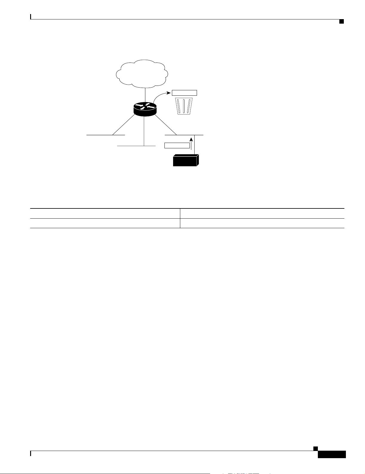
Configuring IP Addressing
Assigning IP Addresses to Network Interfaces
Figure 2 No IP Classless Routing
128.0.0.0/8
128.20.4.1
128.20.0.0
128.20.1.0
128.20.2.0
Bit bucket
128.20.3.0
128.20.4.1
Host
To prevent the Cisco IOS software from forwarding packets destined for unrecognized subnets to the best
supernet route possible, use the following command in global configuration mode:
Command Purpose
Router(config)# no ip classless
Disables classless routing behavior.
Enabling IP Processing on a Serial Interface
You might want to enable IP processing on a serial or tunnel interface without assigning an explicit IP
address to the interface. Whenever the unnumbered interface generates a packet (for example, for a
routing update), it uses the address of the interface you specified as the source address of the IP packet.
It also uses the specified interface address in determining which routing processes are sending updates
over the unnumbered interface. Restrictions are as follows:
S3285
• Serial interfaces using High-Level Data Link Control (HDLC), PPP, Link Access Procedure,
Balanced (LAPB), and Frame Relay encapsulations, as well as Serial Line Internet Protocol (SLIP)
tunnel interfaces, can be unnumbered. Serial interfaces using Frame Relay encapsulation can also
be unnumbered, but the interface must be a point-to-point subinterface. It is not possible to use the
unnumbered interface feature with X.25 or Switched Multimegabit Data Service (SMDS)
encapsulations.
• You cannot use the ping EXEC command to determine whether the interface is up, because the
interface has no IP address. The Simple Network Management Protocol (SNMP) can be used to
remotely monitor interface status.
• You cannot netboot a runnable image over an unnumbered serial interface.
• You cannot support IP security options on an unnumbered interface.
If you are configuring Intermediate System-to-Intermediate System (IS-IS) across a serial line, you
should configure the serial interfaces as unnumbered, which allows you to conform with RFC 1195,
which states that IP addresses are not required on each interface.
Cisco IOS IP Configuration Guide
IPC-11
Page 58

Configuring Address Resolution Methods
Note Using an unnumbered serial line between different major networks requires special care. If, at each
end of the link, different major networks are assigned to the interfaces you specified as unnumbered,
any routing protocols running across the serial line should be configured to not advertise subnet
information.
To enable IP processing on an unnumbered serial interface, use the following command in interface
configuration mode:
Command Purpose
Router(config-if)# ip unnumbered type number
The interface you specify must be the name of another interface in the router that has an IP address, not
another unnumbered interface.
The interface you specify also must be enabled (listed as “up” in the show interfaces command display).
See the “Serial Interfaces Configuration Example” section at the end of this chapter for an example of
how to configure serial interfaces.
Enables IP processing on a serial or tunnel interface without
assigning an explicit IP address to the interface.
Configuring IP Addressing
Configuring Address Resolution Methods
The Cisco IP implementation allows you to control interface-specific handling of IP addresses by
facilitating address resolution, name services, and other functions. The following sections describe how
to configure address resolution methods:
• Establishing Address Resolution
• Mapping Host Names to IP Addresses
• Configuring HP Probe Proxy Name Requests
• Configuring the Next Hop Resolution Protocol
Establishing Address Resolution
A device in the IP can have both a local address (which uniquely identifies the device on its local segment
or LAN) and a network address (which identifies the network to which the device belongs). The local
address is more properly known as a data link address because it is contained in the data link layer
(Layer 2 of the OSI model) part of the packet header and is read by data-link devices (bridges and all
device interfaces, for example). The more technically inclined person will refer to local addresses as
MAC addresses, because the MAC sublayer within the data link layer processes addresses for the layer.
To communicate with a device on Ethernet, for example, the Cisco IOS software first must determine the
48-bit MAC or local data-link address of that device. The process of determining the local data-link
address from an IP address is called address resolution. The process of determining the IP address from
a local data-link address is called reverse address resolution.
IPC-12
Cisco IOS IP Configuration Guide
Page 59

Configuring IP Addressing
Configuring Address Resolution Methods
The software uses three forms of address resolution: Address Resolution Protocol (ARP), proxy ARP,
and Probe (similar to ARP). The software also uses the Reverse Address Resolution Protocol (RARP).
ARP, proxy ARP, and RARP are defined in RFCs 826, 1027, and 903, respectively. Probe is a protocol
developed by the Hewlett-Packard Company (HP) for use on IEEE-802.3 networks.
ARP is used to associate IP addresses with media or MAC addresses. Taking an IP address as input, ARP
determines the associated media address. Once a media or MAC address is determined, the IP address
or media address association is stored in an ARP cache for rapid retrieval. Then the IP datagram is
encapsulated in a link-layer frame and sent over the network. Encapsulation of IP datagrams and ARP
requests and replies on IEEE 802 networks other than Ethernet is specified by the Subnetwork Access
Protocol (SNAP).
RARP works the same way as ARP, except that the RARP request packet requests an IP address instead
of a local data-link address. Use of RARP requires a RARP server on the same network segment as the
router interface. RARP often is used by diskless nodes that do not know their IP addresses when they
boot. The Cisco IOS software attempts to use RARP if it does not know the IP address of an interface at
startup. Also, Cisco routers can act as RARP servers by responding to RARP requests that they are able
to answer. See the “Configure Additional File Transfer Functions” chapter in the Cisco IOS
Configuration Fundamentals Configuration Guide to learn how to configure a router as a RARP server.
The tasks required to set address resolution are contained in the following sections:
• Defining a Static ARP Cache
• Setting ARP Encapsulations
• Enabling Proxy ARP
• Configuring Local-Area Mobility
Defining a Static ARP Cache
ARP and other address resolution protocols provide a dynamic mapping between IP addresses and media
addresses. Because most hosts support dynamic address resolution, generally you need not specify static
ARP cache entries. If you must define them, you can do so globally. Performing this task installs a
permanent entry in the ARP cache. The Cisco IOS software uses this entry to translate 32-bit IP
addresses into 48-bit hardware addresses.
Optionally, you can specify that the software respond to ARP requests as if it were the owner of the
specified IP address. In case you do not want the ARP entries to be permanent, you have the option of
specifying an ARP entry timeout period when you define ARP entries.
The following two tables list the tasks to provide static mapping between IP addresses and a media
address.
Use either of the following commands in global configuration mode to specify that the software respond
to ARP requests:
Command Purpose
Router(config)# arp ip-address hardware-address type
Router(config)# arp ip-address hardware-address type
alias
Globally associates an IP address with a media (hardware)
address in the ARP cache.
Specifies that the software responds to ARP requests as if it
were the owner of the specified IP address.
Cisco IOS IP Configuration Guide
IPC-13
Page 60

Configuring Address Resolution Methods
Use the following command in interface configuration mode to set the length of time an ARP cache entry
will stay in the cache:
Command Purpose
Router(config-if)# arp timeout seconds
Sets the length of time an ARP cache entry will stay in the cache.
To display the type of ARP being used on a particular interface and also display the ARP timeout value,
use the show interfaces EXEC command. Use the show arp EXEC command to examine the contents
of the ARP cache. Use the show ip arp EXEC command to show IP entries. To remove all nonstatic
entries from the ARP cache, use the clear arp-cache privileged EXEC command.
Setting ARP Encapsulations
By default, standard Ethernet-style ARP encapsulation (represented by the arpa keyword) is enabled on
the IP interface. You can change this encapsulation method to SNAP or HP Probe, as required by your
network, to control the interface-specific handling of IP address resolution into 48-bit Ethernet hardware
addresses.
Configuring IP Addressing
When you set HP Probe encapsulation, the Cisco IOS software uses the Probe protocol whenever it
attempts to resolve an IEEE-802.3 or Ethernet local data-link address. The subset of Probe that performs
address resolution is called Virtual Address Request and Reply. Using Probe, the router can
communicate transparently with HP IEEE-802.3 hosts that use this type of data encapsulation. You must
explicitly configure all interfaces for Probe that will use Probe.
To specify the ARP encapsulation type, use the following command in interface configuration mode:
Command Purpose
Router(config-if)# arp {arpa | probe |
snap}
Specifies one of three ARP encapsulation methods for a specified interface.
Enabling Proxy ARP
The Cisco IOS software uses proxy ARP (as defined in RFC 1027) to help hosts with no knowledge of
routing determine the media addresses of hosts on other networks or subnets. For example, if the router
receives an ARP request for a host that is not on the same interface as the ARP request sender, and if the
router has all of its routes to that host through other interfaces, then it generates a proxy ARP reply
packet giving its own local data-link address. The host that sent the ARP request then sends its packets
to the router, which forwards them to the intended host. Proxy ARP is enabled by default.
To enable proxy ARP if it has been disabled, use the following command in interface configuration mode
(as needed) for your network:
Command Purpose
Router(config-if)# ip proxy-arp
Cisco IOS IP Configuration Guide
Enables proxy ARP on the interface.
IPC-14
Page 61

Configuring IP Addressing
Configuring Local-Area Mobility
Local-area mobility provides the ability to relocate IP hosts within a limited area without reassigning
host IP addresses and without changes to the host software. Local-area mobility is supported on Ethernet,
Token Ring, and FDDI interfaces only.
To create a mobility area with only one router, use the following commands in the interface configuration
mode:
Command Purpose
Step 1
Step 2
Router(config-if)# interface type number
Router(config-if)# ip mobile arp [timers keepalive
hold-time] [access-group access-list-number | name]
To create larger mobility areas, you must first redistribute the mobile routes into your Interior Gateway
Protocol (IGP). The IGP must support host routes. You can use Enhanced Interior Gateway Routing
Protocol (IGRP), Open Shortest Path First (OSPF), IS-IS, or RIPv2. To redistribute the mobile routes
into your existing IGP configuration, use the following commands in configuration mode:
Configuring Address Resolution Methods
Enters interface configuration mode.
Enables local-area mobility.
Command Purpose
Step 1
Step 2
Router(config)# router {eigrp autonomous-system |
isis [tag] | ospf process-id | rip}
Router(config)# default-metric number
or
Router(config)# default-metric bandwidth delay
reliability loading mtu
Step 3
Router(config)# redistribute mobile
Mobile routes will always be preferred over a subnet boundary or summarized route because they are
more specific. It is important to ensure that configured or redistributed static routes do not include any
host routes for the potentially mobile hosts; otherwise, a longest match could come up with two routes
and cause ambiguity. Mobile routes will be seen as external routes to the configured routing protocol,
even within a summarization area; therefore, they will not be properly summarized by default. This is
the case even when these routes are advertised at a summarization boundary, if mobile hosts are not on
their home subnet.
Mapping Host Names to IP Addresses
Each unique IP address can have an associated host name. The Cisco IOS software maintains a cache of
host name-to-address mappings for use by the connect, telnet, and ping EXEC commands, and related
Telnet support operations. This cache speeds the process of converting names to addresses.
IP defines a naming scheme that allows a device to be identified by its location in the IP. This is a
hierarchical naming scheme that provides for domains. Domain names are pieced together with periods
(.) as the delimiting characters. For example, Cisco is a commercial organization that the IP identifies
by a com domain name, so its domain name is cisco.com. A specific device in this domain, the File
Transfer Protocol (FTP) system, for example, is identified as ftp.cisco.com.
Enters router configuration mode.
Sets default metric values.
Redistributes the mobile routes.
Cisco IOS IP Configuration Guide
IPC-15
Page 62

Configuring Address Resolution Methods
To keep track of domain names, IP has defined the concept of a name server, whose job is to hold a cache
(or database) of names mapped to IP addresses. To map domain names to IP addresses, you must first
identify the host names, then specify a name server, and enable the Domain Naming System (DNS), the
global naming scheme of the Internet that uniquely identifies network devices. These tasks are described
in the following sections:
• Assigning Host Names to IP Addresses
• Specifying the Domain Name
• Specifying a Name Server
• Enabling the DNS
• Using the DNS to Discover ISO CLNS Addresses
Assigning Host Names to IP Addresses
The Cisco IOS software maintains a table of host names and their corresponding addresses, also called
a host name-to-address mapping. Higher-layer protocols such as Telnet use host names to identify
network devices (hosts). The router and other network devices must be able to associate host names with
IP addresses to communicate with other IP devices. Host names and IP addresses can be associated with
one another through static or dynamic means.
Manually assigning host names to addresses is useful when dynamic mapping is not available.
Configuring IP Addressing
To assign host names to addresses, use the following command in global configuration mode:
Command Purpose
Router(config)# ip host name [tcp-port-number]
address1 [address2...address8]
Statically associates host names with IP addresses.
Specifying the Domain Name
You can specify a default domain name that the Cisco IOS software will use to complete domain name
requests. You can specify either a single domain name or a list of domain names. Any IP host name that
does not contain a domain name will have the domain name you specify appended to it before being
added to the host table.
To specify a domain name or names, use either of the following commands in global configuration mode:
Command Purpose
Router(config)# ip domain name name
Router(config)# ip domain list name
See the “IP Domains Example” section at the end of this chapter for an example of establishing IP
domains.
Defines a default domain name that the Cisco IOS software will use
to complete unqualified host names.
Defines a list of default domain names to complete unqualified host
names.
IPC-16
Cisco IOS IP Configuration Guide
Page 63

Configuring IP Addressing
Specifying a Name Server
To specify one or more hosts (up to six) that can function as a name server to supply name information
for the DNS, use the following command in global configuration mode:
Command Purpose
Router(config)# ip name-server
server-address1
[server-address2...server-address6]
Specifies one or more hosts that supply name information.
Enabling the DNS
If your network devices require connectivity with devices in networks for which you do not control name
assignment, you can assign device names that uniquely identify your devices within the entire
internetwork. The global naming scheme of the Internet, the DNS, accomplishes this task. This service
is enabled by default.
To re-enable DNS if it has been disabled, use the following command in global configuration mode:
Configuring Address Resolution Methods
Command Purpose
Router(config)# ip domain lookup
Enables DNS-based host name-to-address translation.
See the “Dynamic Lookup Example” section at the end of this chapter for an example of enabling the
DNS.
Using the DNS to Discover ISO CLNS Addresses
If your router has both IP and ISO Connectionless Network Service (ISO CLNS) enabled and you want
to use ISO CLNS network service access point (NSAP) addresses, you can use the DNS to query these
addresses, as documented in RFC 1348. This feature is enabled by default.
To disable DNS queries for ISO CLNS addresses, use the following command in global configuration
mode:
Command Purpose
Router(config)# no ip domain-lookup
nsap
Disables DNS queries for ISO CLNS addresses.
Cisco IOS IP Configuration Guide
IPC-17
Page 64

Configuring Address Resolution Methods
Configuring HP Probe Proxy Name Requests
HP Probe Proxy support allows the Cisco IOS software to respond to HP Probe Proxy name requests.
These requests are typically used at sites that have HP equipment and are already using HP Probe Proxy.
Tasks associated with HP Probe Proxy are shown in the following two tables.
To configure HP Probe Proxy, use the following command in interface configuration mode:
Command Purpose
Router(config-if)# ip probe proxy
To configure HP Probe Proxy, use the following command in global configuration mode:
Command Purpose
Router(config)# ip hp-host hostname ip-address
Allows the Cisco IOS software to respond to HP Probe Proxy name
requests.
Enters the host name of an HP host (for which the router is acting as
a proxy) into the host table.
Configuring IP Addressing
See the “HP Hosts on a Network Segment Example” section at the end of this chapter for an example of
configuring HP hosts on a network segment.
Configuring the Next Hop Resolution Protocol
Routers, access servers, and hosts can use Next Hop Resolution Protocol (NHRP) to discover the
addresses of other routers and hosts connected to a nonbroadcast multiaccess (NBMA) network.
Partially meshed NBMA networks are typically configured with multiple logical networks to provide
full network layer connectivity. In such configurations, packets might make several hops over the NBMA
network before arriving at the exit router (the router nearest the destination network). In addition, such
NBMA networks (whether partially or fully meshed) typically require tedious static configurations.
These static configurations provide the mapping between network layer addresses (such as IP) and
NBMA addresses (such as E.164 addresses for SMDS).
NHRP provides an ARP-like solution that alleviates these NBMA network problems. With NHRP,
systems attached to an NBMA network dynamically learn the NBMA address of the other systems that
are part of that network, allowing these systems to directly communicate without requiring traffic to use
an intermediate hop.
The NBMA network is considered nonbroadcast either because it technically does not support
broadcasting (for example, an X.25 network) or because broadcasting is too expensive (for example, an
SMDS broadcast group that would otherwise be too large).
The Cisco Implementation of NHRP
IPC-18
The Cisco implementation of NHRP supports the IETF draft version 11 of NBMA Next Hop Resolution
Protocol (NHRP).
The Cisco implementation of NHRP supports IP Version 4, Internet Packet Exchange (IPX) network
layers, and, at the link layer, ATM, Ethernet, SMDS, and multipoint tunnel networks. Although NHRP
is available on Ethernet, NHRP need not be implemented over Ethernet media because Ethernet is
capable of broadcasting. Ethernet support is unnecessary (and not provided) for IPX.
Cisco IOS IP Configuration Guide
Page 65

Configuring IP Addressing
Configuring Address Resolution Methods
Figure 3 illustrates four routers connected to an NBMA network. Within the network are ATM or SMDS
switches necessary for the routers to communicate with each other. Assume that the switches have virtual
circuit (VC) connections represented by hops 1, 2, and 3 of the figure. When Router A attempts to
forward an IP packet from the source host to the destination host, NHRP is triggered. On behalf of the
source host, Router A sends an NHRP request packet encapsulated in an IP packet, which takes three
hops across the network to reach Router D, connected to the destination host. After receiving a positive
NHRP reply, Router D is determined to be the “NBMA next hop,” and Router A sends subsequent IP
packets for the destination to Router D in one hop.
Figure 3 Next Hop Resolution Protocol
Destination
host
NBMA next hop
Router D
Hop 3
Router C
NBMA network
Router A
Subsequent
IP packets
IP NHRP
Hop 1
Source
host
Hop 2
Router B
S3229
With NHRP, once the NBMA next hop is determined, the source either starts sending data packets to the
destination (in a connectionless NBMA network such as SMDS) or establishes a virtual circuit VC
connection to the destination with the desired bandwidth and quality of service (QoS) characteristics (in
a connection-oriented NBMA network such as ATM).
Other address resolution methods can be used while NHRP is deployed. IP hosts that rely upon the
Logical IP Subnet (LIS) model might require ARP servers and services over NBMA networks, and
deployed hosts might not implement NHRP, but might continue to support ARP variations. NHRP is
designed to eliminate the suboptimal routing that results from the LIS model, and can be deployed with
existing ARP services without interfering with them.
NHRP is used to facilitate building a Virtual Private Network (VPN). In this context, a VPN consists of
a virtual Layer 3 network that is built on top of an actual Layer 3 network. The topology you use over
the VPN is largely independent of the underlying network, and the protocols you run over it are
completely independent of it.
Connected to the NBMA network are one or more stations that implement NHRP, and are known as Next
Hop Servers. All routers running Cisco IOS Release 10.3 or later releases can implement NHRP and,
thus, can act as Next Hop Servers.
Cisco IOS IP Configuration Guide
IPC-19
Page 66

Configuring Address Resolution Methods
Each Next Hop Server serves a set of destination hosts, which might be directly connected to the NBMA
network. Next Hop Servers cooperatively resolve the NBMA next hop addresses within their NBMA
network. Next Hop Servers typically also participate in protocols used to disseminate routing
information across (and beyond the boundaries of) the NBMA network, and might support ARP service.
A Next Hop Server maintains a “next hop resolution” cache, which is a table of network layer address
to NBMA address mappings. The table is created from information gleaned from NHRP register packets
extracted from NHRP request or reply packets that traverse the Next Hop Server as they are forwarded,
or through other means such as ARP and preconfigured tables.
Protocol Operation
NHRP requests traverse one or more hops within an NBMA subnetwork before reaching the station that
is expected to generate a response. Each station (including the source station) chooses a neighboring
Next Hop Server to forward the request to. The Next Hop Server selection procedure typically involves
performing a routing decision based upon the network layer destination address of the NHRP request.
Ignoring error situations, the NHRP request eventually arrives at a station that generates an NHRP reply.
This responding station either serves the destination, is the destination itself, or is a client that specified
it should receive NHRP requests when it registered with its server. The responding station generates a
reply using the source address from within the NHRP packet to determine where the reply should be sent.
Configuring IP Addressing
NHRP Configuration Task List
To configure NHRP, perform the tasks described in the following sections. The tasks in the first section
are required; the tasks in the remaining sections are optional.
• Enabling NHRP on an Interface (Required)
• Configuring a Static IP-to-NBMA Address Mapping for a Station (Optional)
• Statically Configuring a Next Hop Server (Optional)
• Configuring NHRP Authentication (Optional)
• Controlling the Triggering of NHRP (Optional)
• Triggering NHRP Based on Traffic Thresholds (Optional)
• Controlling the NHRP Packet Rate (Optional)
• Suppressing Forward and Reverse Record Options (Optional)
• Specifying the NHRP Responder Address (Optional)
• Changing the Time Period NBMA Addresses Are Advertised as Valid (Optional)
• Configuring a GRE Tunnel for Multipoint Operation (Optional)
• Configuring NHRP Server-Only Mode (Optional)
IPC-20
Cisco IOS IP Configuration Guide
Page 67

Configuring IP Addressing
Enabling NHRP on an Interface
To enable NHRP for an interface on a router, use the following command in interface configuration
mode. In general, all NHRP stations within a logical NBMA network must be configured with the same
network identifier.
Command Purpose
Router(config-if)# ip nhrp network-id number
Enables NHRP on an interface.
See the “Logical NBMA Example” section and the “NHRP over ATM Example” section at the end of
this chapter for examples of enabling NHRP.
Configuring a Static IP-to-NBMA Address Mapping for a Station
To participate in NHRP, a station connected to an NBMA network should be configured with the IP and
NBMA addresses of its Next Hop Servers. The format of the NBMA address depends on the medium
you are using. For example, ATM uses an NSAP address, Ethernet uses a MAC address, and SMDS uses
an E.164 address.
These Next Hop Servers may also be the default or peer routers of the station, so their addresses can be
obtained from the network layer forwarding table of the station.
If the station is attached to several link layer networks (including logical NBMA networks), the station
should also be configured to receive routing information from its Next Hop Servers and peer routers so
that it can determine which IP networks are reachable through which link layer networks.
Configuring Address Resolution Methods
To configure static IP-to-NBMA address mapping on a station (host or router), use the following
command in interface configuration mode:
Command Purpose
Router(config-if)# ip nhrp map ip-address
nbma-address
Configures static IP-to-NBMA address mapping.
Statically Configuring a Next Hop Server
A Next Hop Server normally uses the network layer forwarding table to determine where to forward
NHRP packets, and to find the egress point from an NBMA network. A Next Hop Server may alternately
be statically configured with a set of IP address prefixes that correspond to the IP addresses of the
stations it serves, and their logical NBMA network identifiers.
To statically configure a Next Hop Server, use the following command in interface configuration mode:
Command Purpose
Router(config-if)# ip nhrp nhs nhs-address
[net-address [netmask]]
To configure multiple networks that the Next Hop Server serves, repeat the ip nhrp nhs command with
the same Next Hop Server address, but different IP network addresses. To configure additional Next Hop
Servers, repeat the ip nhrp nhs command.
Statically configures a Next Hop Server.
Cisco IOS IP Configuration Guide
IPC-21
Page 68

Configuring Address Resolution Methods
Configuring NHRP Authentication
Configuring an authentication string ensures that only routers configured with the same string can
communicate using NHRP. Therefore, if the authentication scheme is to be used, the same string must
be configured in all devices configured for NHRP on a fabric. To specify the authentication string for
NHRP on an interface, use the following command in interface configuration mode:
Command Purpose
Router(config-if)# ip nhrp authentication string
Specifies an authentication string.
Controlling the Triggering of NHRP
On any platform, there are two ways to control when NHRP is triggered. These methods are described
in the following sections:
• Triggering NHRP by IP Packets
• Triggering NHRP on a per-Destination Basis
Configuring IP Addressing
Triggering NHRP by IP Packets
You can specify an IP access list that is used to decide which IP packets can trigger the sending of NHRP
requests. By default, all non-NHRP packets trigger NHRP requests. To limit which IP packets trigger
NHRP requests, define an access list and then apply it to the interface.
To define an access list, use the following commands in global configuration mode as needed:
Command Purpose
Router(config)# access-list access-list-number {deny | permit} source
[source-wildcard]
Router(config)# access-list access-list-number {deny | permit}
protocol source source-wildcard destination destination-wildcard
[precedence precedence] [tos tos] [established] [log]
Defines a standard IP access list.
Defines an extended IP access list.
To apply the IP access list to the interface, use the following command in interface configuration mode:
Command Purpose
Router(config-if)# ip nhrp interest access-list-number
Specifies an IP access list that controls
NHRP requests.
IPC-22
Cisco IOS IP Configuration Guide
Page 69

Configuring IP Addressing
Triggering NHRP on a per-Destination Basis
By default, when the software attempts to send a data packet to a destination for which it has determined
that NHRP can be used, it sends an NHRP request for that destination. To configure the system to wait
until a specified number of data packets have been sent to a particular destination before NHRP is
attempted, use the following command in interface configuration mode:
Command Purpose
Router(config-if)# ip nhrp use usage-count
Specifies how many data packets are sent to a destination before NHRP
is attempted.
Triggering NHRP Based on Traffic Thresholds
NHRP can run on Cisco Express Forwarding (CEF) platforms when NHRP runs with BGP over ATM
media. You can configure NHRP to initiate switched virtual circuits (SVCs) once a configured traffic
rate is reached. Similarly, SVCs can be torn down when traffic falls to another configured rate.
Prior to Cisco IOS Release 12.0, a single packet could trigger an SVC. Now you can configure the traffic
rate that must be reached before NHRP sets up or tears down an SVC. Because SVCs are created only
for burst traffic, you can conserve resources.
Configuring Address Resolution Methods
Restrictions
Prerequisites
Cisco IOS releases prior to Release 12.0 implemented NHRP draft version 4. Cisco IOS Release 12.0
and later implements NHRP draft version 11. These versions are not compatible. Therefore, all routers
running NHRP in a network must run the same version of NHRP in order to communicate with each
other. All routers must run Cisco IOS Release 12.0 and later, or all routers must run a release prior to
Release 12.0, but not a combination of the two.
Additional restrictions:
• They work on CEF platforms only.
• They work on ATM media only.
• BGP must be configured in the network where these enhancements are running.
Before you configure the feature whereby NHRP initiation is based on traffic rate, the following
conditions must exist in the router:
• ATM must be configured.
• CEF switching or distributed CEF (dCEF) switching must be enabled.
• BGP must be configured on all routers in the network.
If you have CEF switching or dCEF switching and you want NHRP to work (whether with default values
or changed values), the ip cef accounting non-recursive command must be configured.
Cisco IOS IP Configuration Guide
IPC-23
Page 70

Configuring Address Resolution Methods
NHRP Configuration Task List
To configure the NHRP triggering and teardown of SVCs based on traffic rate, perform the tasks
described in the following sections. The tasks in the first section are required, the tasks in the remaining
section are optional.
• Changing the Rate for Triggering SVCs (Required)
• Applying the Rates to Specific Destinations (Optional)
Changing the Rate for Triggering SVCs
When NHRP runs with BGP over ATM media, there is an additional way to control the triggering of
NHRP packets. This method consists of SVCs being initiated based on the input traffic rate to a given
BGP next hop.
When BGP discovers a BGP next hop and enters this BGP route into the routing table, an NHRP request
is sent to the BGP next hop. When an NHRP reply is received, a subsequent route is put in the NHRP
cache that directly corresponds to the BGP next hop.
A new NHRP request is sent to the same BGP next hop to repopulate the NHRP cache. When an NHRP
cache entry is generated, a subsequent ATM map statement to the same BGP next hop is also created.
Configuring IP Addressing
Aggregate traffic to each BGP next hop is measured and monitored. Once the aggregate traffic has met
or exceeded the configured trigger rate, NHRP creates an ATM SVC and sends traffic directly to that
destination router. The router tears down the SVC to the specified destination(s) when the aggregate
traffic rate falls to or below the configured teardown rate.
By default, NHRP will set up an SVC for a destination when aggregate traffic for that destination is more
than 1 kbps over a running average of 30 seconds. Similarly, NHRP will tear down the SVC when the
traffic for that destination drops to 0 kbps over a running average of 30 seconds. There are several ways
to change the rate at which SVC set or teardown occurs. You can change the number of kbps thresholds,
or the load interval, or both.
To change the number of kbps at which NHRP sets up or tears down the SVC to this destination, use the
following command in interface configuration mode:
Command Purpose
Router(config-if)# ip nhrp trigger-svc trigger-threshold
teardown-threshold
Changes the point at which NHRP sets up or tears
down SVCs.
You can change the sampling time period; that is, you can change the length of time over which the
average trigger rate or teardown rate is calculated. By default, the period is 30 seconds; the range is from
30 to 300 seconds in 30-second increments. This period is for calculations of aggregate traffic rate
internal to Cisco IOS software only, and it represents a worst case time period for taking action. In some
cases, the software will act sooner, depending on the ramp-up and fall-off rate of the traffic.
To change the sampling time period during which threshold rates are averaged, use the following
command in global configuration mode:
Command Purpose
Router(config)# ip cef traffic-statistics [load-interval
seconds]
Changes the length of time in a sampling period
during which trigger and teardown thresholds are
averaged.
Cisco IOS IP Configuration Guide
IPC-24
Page 71

Configuring IP Addressing
If your Cisco hardware has a Virtual Interface Processor, version 2 adapter, you must perform the
following task to change the sampling time. By default, the port adapter sends the traffic statistics to the
Route Processor every 10 seconds. If you are using NHRP in dCEF switching mode, you must change
this update rate to 5 seconds. To do so, use the following command in global configuration mode:
Command Purpose
Router(config)# ip cef traffic-statistics [update-rate
seconds]
Changes the rate at which the port adapter sends
traffic statistics to the RP.
Applying the Rates to Specific Destinations
By default, all destinations are measured and monitored for NHRP triggering. However, you can choose
to impose the triggering and teardown rates on certain destinations. To do so, use the following
commands beginning in global configuration mode:
Command Purpose
Step 1
Router(config)# access-list access-list-number {deny |
permit} source [source-wildcard]
Defines a standard or extended IP access list.
Configuring Address Resolution Methods
or
access-list access-list-number {deny | permit}
protocol source source-wildcard destination
destination-wildcard [precedence precedence] [tos tos]
[log]
Step 2
Step 3
Router(config)# interface type number
Router(interface config)# ip nhrp interest access-list
Enters interface configuration mode.
Assigns the access list created in Step 1 that
determines which destinations are included in or
excluded from the SVC triggering.
For an example of setting the load interval, see the section “Changing the Rate for Triggering SVCs
Example” at the end of this chapter. For an example of applying rates to destinations, see the section
“Applying NHRP Rates to Specific Destinations Example” at the end of this chapter.
Controlling the NHRP Packet Rate
By default, the maximum rate at which the software sends NHRP packets is 5 packets per 10 seconds.
The software maintains a per- interface quota of NHRP packets (whether generated locally or forwarded)
that can be sent. To change this maximum rate, use the following command in interface configuration
mode:
Command Purpose
Router(config-if)# ip nhrp max-send pkt-count every interval
Changes the NHRP packet rate per interface.
Cisco IOS IP Configuration Guide
IPC-25
Page 72

Configuring Address Resolution Methods
Suppressing Forward and Reverse Record Options
To dynamically detect link layer filtering in NBMA networks (for example, SMDS address screens), and
to provide loop detection and diagnostic capabilities, NHRP incorporates a Route Record in request and
reply packets. The Route Record options contain the network (and link layer) addresses of all
intermediate Next Hop Servers between source and destination (in the forward direction) and between
destination and source (in the reverse direction).
By default, Forward Record options and Reverse Record options are included in NHRP request and reply
packets. To suppress the use of these options, use the following command in interface configuration
mode:
Command Purpose
Router(config-if)# no ip nhrp record
Suppresses Forward and Reverse Record options.
Specifying the NHRP Responder Address
If an NHRP requester wants to know which Next Hop Server generates an NHRP reply packet, it can
request that information by including the responder address option in its NHRP request packet. The Next
Hop Server that generates the NHRP reply packet then complies by inserting its own IP address in the
NHRP reply. The Next Hop Server uses the primary IP address of the specified interface.
To specify which interface the Next Hop Server uses for the NHRP responder IP address, use the
following command in interface configuration mode:
Configuring IP Addressing
Command Purpose
Router(config-if)# ip nhrp responder type number
Specifies which interface the Next Hop Server uses to determine
the NHRP responder address.
If an NHRP reply packet being forwarded by a Next Hop Server contains the IP address of that server,
the Next Hop Server generates an error indication of type “NHRP Loop Detected” and discards the reply.
Changing the Time Period NBMA Addresses Are Advertised as Valid
You can change the length of time that NBMA addresses are advertised as valid in positive NHRP
responses. In this context, advertised means how long the Cisco IOS software tells other routers to keep
the addresses it is providing in NHRP responses. The default length of time is 7200 seconds (2 hours).
To change the length of time, use the following command in interface configuration mode:
Command Purpose
Router(config-if)# ip nhrp holdtime seconds
Specifies the number of seconds that NBMA addresses are
advertised as valid in positive NHRP responses.
IPC-26
Cisco IOS IP Configuration Guide
Page 73

Configuring IP Addressing
Configuring a GRE Tunnel for Multipoint Operation
You can enable a generic routing encapsulation (GRE) tunnel to operate in multipoint fashion. A tunnel
network of multipoint tunnel interfaces can be thought of as an NBMA network. To configure the tunnel,
use the following commands in interface configuration mode:
Command Purpose
Step 1
Step 2
Router(config-if)# tunnel mode gre ip multipoint
Router(config-if)# tunnel key key-number
The tunnel key should correspond to the NHRP network identifier specified in the ip nhrp network-id
interface configuration command. See the “NHRP on a Multipoint Tunnel Example” section at the end
of this chapter for an example of NHRP configured on a multipoint tunnel.
Configuring NHRP Server-Only Mode
You can configure an interface so that it cannot initiate NHRP requests or set up NHRP shortcut SVCs
but can only respond to NHRP requests. Configure NHRP server-only mode on routers you do not want
placing NHRP requests.
If an interface is placed in NHRP server-only mode, you have the option to specify the non-caching
keyword. In this case, NHRP does not store information in the NHRP cache, such as NHRP responses
that could be used again. To save memory, the non caching option is generally used on a router located
between two other routers.
To configure NHRP server-only mode, use the following command in interface configuration mode:
Enabling IP Routing
Enables a GRE tunnel to be used in multipoint fashion.
Configures a tunnel identification key.
Command Purpose
Router(config-if)# ip nhrp server-only [non-caching]
Configures NHRP server-only mode.
Enabling IP Routing
IP routing is automatically enabled in the Cisco IOS software. If you choose to set up the router to bridge
rather than route IP datagrams, you must disable IP routing. To re-enable IP routing if it has been
disabled, use the following command in global configuration mode:
Command Purpose
Router(config)# ip routing
When IP routing is disabled, the router will act as an IP end host for IP packets destined for or sourced
by it, whether or not bridging is enabled for those IP packets not destined for the device. To re-enable IP
routing, use the ip routing command.
Enables IP routing.
Cisco IOS IP Configuration Guide
IPC-27
Page 74

Enabling IP Routing
Routing Assistance When IP Routing Is Disabled
The Cisco IOS software provides three methods by which the router can learn about routes to other
networks when IP routing is disabled and the device is acting as an IP host. These methods are described
in the sections that follow:
• Proxy ARP
• Default Gateway (also known as default router)
• ICMP Router Discovery Protocol
When IP routing is disabled, the default gateway feature and the router discovery client are enabled, and
proxy ARP is disabled. When IP routing is enabled, the default gateway feature is disabled and you can
configure proxy ARP and the router discovery servers.
Proxy ARP
The most common method of learning about other routes is by using proxy ARP. Proxy ARP, defined in
RFC 1027, enables an Ethernet host with no knowledge of routing to communicate with hosts on other
networks or subnets. Such a host assumes that all hosts are on the same local Ethernet, and that it can
use ARP to determine their hardware addresses.
Under proxy ARP, if a device receives an ARP request for a host that is not on the same network as the
ARP request sender, the Cisco IOS software evaluates whether it has the best route to that host. If it does,
the device sends an ARP reply packet giving its own Ethernet hardware address. The host that sent the
ARP request then sends its packets to the device, which forwards them to the intended host. The software
treats all networks as if they are local and performs ARP requests for every IP address. This feature is
enabled by default. If it has been disabled, see the section “Enabling Proxy ARP” earlier in this chapter.
Configuring IP Addressing
Proxy ARP works as long as other routers support it. Many other routers, especially those loaded with
host-based routing software, do not support it.
Default Gateway
Another method for locating routes is to define a default router (or gateway). The Cisco IOS software
sends all nonlocal packets to this router, which either routes them appropriately or sends an IP Control
Message Protocol (ICMP) redirect message back, telling the router of a better route. The ICMP redirect
message indicates which local router the host should use. The software caches the redirect messages and
routes each packet thereafter as efficiently as possible. The limitations of this method are that there is
no means of detecting when the default router has gone down or is unavailable, and there is no method
of picking another device if one of these events should occur.
To set up a default gateway for a host, use the following command in global configuration mode:
Command Purpose
Router(config)# ip default-gateway ip-address
To display the address of the default gateway, use the show ip redirects EXEC command.
Sets up a default gateway (router).
IPC-28
Cisco IOS IP Configuration Guide
Page 75

Configuring IP Addressing
ICMP Router Discovery Protocol
The Cisco IOS software provides a third method, called router discovery, by which the router
dynamically learns about routes to other networks using the ICMP Router Discovery Protocol IRDP).
IRDP allows hosts to locate routers. When the device operates as a client, router discovery packets are
generated. When the device operates as a host, router discovery packets are received. The Cisco IRDP
implementation fully conforms to the router discovery protocol outlined in RFC 1256.
The software is also capable of wire-tapping Routing Information Protocol (RIP) and Interior Gateway
Routing Protocol (IGRP) routing updates and inferring the location of routers from those updates. The
client/server implementation of router discovery does not actually examine or store the full routing
tables sent by routing devices, it merely keeps track of which systems are sending such data.
You can configure the four protocols in any combination. We recommend that you use IRDP when
possible because it allows each router to specify both a priority and the time after which a device should
be assumed down if no further packets are received. Devices discovered using IGRP are assigned an
arbitrary priority of 60. Devices discovered through RIP are assigned a priority of 50. For IGRP and RIP,
the software attempts to measure the time between updates, and assumes that the device is down if no
updates are received for 2.5 times that interval.
Each device discovered becomes a candidate for the default router. The list of candidates is scanned and
a new highest-priority router is selected when any of the following events occurs:
Enabling IP Routing
• When a higher-priority router is discovered (the list of routers is polled at 5-minute intervals).
• When the current default router is declared down.
• When a TCP connection is about to time out because of excessive retransmissions. In this case, the
server flushes the ARP cache and the ICMP redirect cache, and picks a new default router in an
attempt to find a successful route to the destination.
Enabling IRDP Processing
Only one task for configuring IRDP routing on a specified interface is required. To enable IRDP
processing on an interface, use the following command in interface configuration mode:
Command Purpose
Router(config-if)# ip irdp
Enables IRDP processing on an interface.
Changing IRDP Parameters
When you enable IRDP processing, the default parameters will apply. To optionally change any of these
IRDP parameters, use the following commands in interface configuration mode, as needed:
Command Purpose
Router(config-if)# ip irdp multicast
Sends IRDP advertisements to the all-systems multicast address
(224.0.0.1) on a specified interface.
Router(config-if)# ip irdp holdtime seconds
Router(config-if)# ip irdp maxadvertinterval
seconds
Router(config-if)# ip irdp minadvertinterval
seconds
Sets the IRDP period for which advertisements are valid.
Sets the IRDP maximum interval between advertisements.
Sets the IRDP minimum interval between advertisements.
Cisco IOS IP Configuration Guide
IPC-29
Page 76

Enabling IP Bridging
Command Purpose
Router(config-if)# ip irdp preference number
Router(config-if)# ip irdp address address
[number]
The Cisco IOS software can proxy-advertise other machines that use IRDP; however, this practice is not
recommended because it is possible to advertise nonexistent machines or machines that are down.
Sets the IRDP preference level of the device.
Specifies an IRDP address and preference to proxy-advertise.
Enabling IP Bridging
To transparently bridge IP on an interface, use the following commands beginning in global
configuration mode:
Command Purpose
Step 1
Step 2
Step 3
Router(config)# no ip routing
Router(config)# interface type number
Router(config-if)# bridge-group group
Disables IP routing.
Specifies an interface and enters interface configuration mode.
Adds the interface to a bridge group.
Configuring IP Addressing
Enabling Integrated Routing and Bridging
With integrated routing and bridging (IRB), you can route IP traffic between routed interfaces and bridge
groups, or route IP traffic between bridge groups. Specifically, local or unroutable traffic is bridged
among the bridged interfaces in the same bridge group, while routable traffic is routed to other routed
interfaces or bridge groups. IRB can be used to switch packets in the following ways:
• From a bridged interface to a routed interface
• From a routed interface to a bridged interface
• Within the same bridge group
For more information about configuring integrated routing and bridging, refer to the “Configuring
Transparent Bridging” chapter in the Cisco IOS Bridging and IBM Networking Configuration Guide.
Configuring a Routing Process
At this point in the configuration process, you can choose to configure one or more of the many routing
protocols that are available, based on your individual network needs. Routing protocols provide topology
information of an internetwork. Refer to subsequent chapters in this document for the tasks involved in
configuring IP routing protocols such as BGP, On-Demand Routing (ODR), RIP, IGRP, OSPF, IP
Enhanced IGRP, Integrated IS-IS, and IP multicast routing. If you want to continue to perform IP
addressing tasks, continue reading the following sections.
IPC-30
Cisco IOS IP Configuration Guide
Page 77

Configuring IP Addressing
Configuring Broadcast Packet Handling
A broadcast is a data packet destined for all hosts on a particular physical network. Network hosts
recognize broadcasts by special addresses. Broadcasts are heavily used by some protocols, including
several important Internet protocols. Control of broadcast messages is an essential responsibility of the
IP network administrator.
The Cisco IOS software supports two kinds of broadcasting: directed broadcasting and flooding. A
directed broadcast is a packet sent to a specific network or series of networks, while a flooded broadcast
packet is sent to every network. A directed broadcast address includes the network or subnet fields.
Several early IP implementations do not use the current broadcast address standard. Instead, they use the
old standard, which calls for all 0s instead of all 1s to indicate broadcast addresses. Many of these
implementations do not recognize an all-1s broadcast address and fail to respond to the broadcast
correctly. Others forward all-1s broadcasts, which causes a serious network overload known as a
broadcast storm. Implementations that exhibit these problems include systems based on versions of
Berkeley Standard Distribution (BSD) UNIX prior to Version 4.3.
Routers provide some protection from broadcast storms by limiting their extent to the local cable.
Bridges (including intelligent bridges), because they are Layer 2 devices, forward broadcasts to all
network segments, thus propagating all broadcast storms.
The best solution to the broadcast storm problem is to use a single broadcast address scheme on a
network. Most modern IP implementations allow the network manager to set the address to be used as
the broadcast address. Many implementations, including the one in the Cisco IOS software, accept and
interpret all possible forms of broadcast addresses.
For detailed discussions of broadcast issues in general, see RFC 919, Broadcasting Internet Datagrams,
and RFC 922, Broadcasting IP Datagrams in the Presence of Subnets. The support for Internet
broadcasts generally complies with RFC 919 and RFC 922; it does not support multisubnet broadcasts
as defined in RFC 922.
Configuring Broadcast Packet Handling
The current broadcast address standard provides specific addressing schemes for forwarding broadcasts.
To enable these schemes, perform the tasks described in the following sections. The task in the first
section is required; the tasks in the remaining sections are optional.
• Enabling Directed Broadcast-to-Physical Broadcast Translation (Required)
• Forwarding UDP Broadcast Packets and Protocols (Optional)
• Establishing an IP Broadcast Address (Optional)
• Flooding IP Broadcasts (Optional)
See the “Broadcasting Examples” section at the end of this chapter for broadcasting configuration
examples.
Enabling Directed Broadcast-to-Physical Broadcast Translation
By default, IP directed broadcasts are dropped; they are not forwarded. Dropping IP directed broadcasts
makes routers less susceptible to denial-of-service attacks.
You can enable forwarding of IP directed broadcasts on an interface where the broadcast becomes a
physical broadcast. If such forwarding is enabled, only those protocols configured using the
ip forward-protocol global configuration command are forwarded.
You can specify an access list to control which broadcasts are forwarded. When an access list is
specified, only those IP packets permitted by the access list are eligible to be translated from directed
broadcasts to physical broadcasts.
Cisco IOS IP Configuration Guide
IPC-31
Page 78

Configuring Broadcast Packet Handling
To enable forwarding of IP directed broadcasts, use the following command in interface configuration
mode:
Command Purpose
Router(config-if)# ip directed-broadcast
[access-list-number]
Enables directed broadcast-to-physical broadcast translation
on an interface.
Forwarding UDP Broadcast Packets and Protocols
Network hosts occasionally use User Datagram Protocol (UDP) broadcasts to determine address,
configuration, and name information. If such a host is on a network segment that does not include a
server, UDP broadcasts normally are not forwarded. You can remedy this situation by configuring the
interface of your router to forward certain classes of broadcasts to a helper address. You can use more
than one helper address per interface.
You can specify a UDP destination port to control which UDP services are forwarded. You can specify
multiple UDP protocols. You can also specify the Network Disk (ND) protocol, which is used by older
diskless Sun workstations, and you can specify the network security protocol, Software Defined
Network Service (SDNS). By default, both UDP and ND forwarding are enabled if a helper address has
been defined for an interface. The description for the ip forward-protocol global configuration
command in the Cisco IOS IPCommand Reference, Volume 1 of 3: Addressing and Services publication
lists the ports that are forwarded by default if you do not specify any UDP ports.
Configuring IP Addressing
If you do not specify any UDP ports when you configure the forwarding of UDP broadcasts, you are
configuring the router to act as a BOOTP forwarding agent. BOOTP packets carry Dynamic Host
Configuration Protocol (DHCP) information, which means that the Cisco IOS software is compatible
with DHCP clients. (DHCP is defined in RFC 1531.)
To enable forwarding and to specify the destination address, use the following command in interface
configuration mode:
Command Purpose
Router(config-if)# ip helper-address address
Enables forwarding and specifies the destination address for
forwarding UDP broadcast packets, such as BOOTP and
DHCP.
To specify which protocols will be forwarded, use the following command in global configuration mode:
Command Purpose
Router(config)# ip forward-protocol {udp [port] | nd
| sdns}
Specifies which protocols will be forwarded over which ports.
See the “Helper Addresses Example” section at the end of this chapter for an example of how to
configure helper addresses.
IPC-32
Cisco IOS IP Configuration Guide
Page 79

Configuring IP Addressing
Establishing an IP Broadcast Address
The Cisco IOS software supports IP broadcasts on both LANs and WANs. There are several ways to
indicate an IP broadcast address. Currently, the most popular way, and the default, is an address
consisting of all 1s (255.255.255.255), although the software can be configured to generate any form of
IP broadcast address. Cisco software can receive and understand any form of IP broadcast.
To set the IP broadcast address, use the following command in interface configuration mode:
Command Purpose
Router(config-if)# ip broadcast-address
[ip-address]
If the router does not have nonvolatile memory, and you need to specify the broadcast address to use
before the software is configured, you must change the IP broadcast address by setting jumpers in the
processor configuration register. Setting bit 10 causes the device to use all 0s. Bit 10 interacts with bit
14, which controls the network and subnet portions of the broadcast address. Setting bit 14 causes the
device to include the network and subnet portions of its address in the broadcast address. Table 4 shows
the combined effect of setting bits 10 and 14.
Establishes a different broadcast address (other than 255.255.255.255).
Configuring Broadcast Packet Handling
Table 4 Configuration Register Settings for Broadcast Address Destination
Bit 14 Bit 10 Address (<net><host>)
Out Out <ones><ones>
Out In <zeros><zeros>
In In <net><zeros>
In Out <net><ones>
Some router platforms allow the configuration register to be set through the software; see the
“Rebooting” chapter of the Cisco IOS Configuration Fundamentals Configuration Guide for details. For
other router platforms, the configuration register must be changed through hardware; see the appropriate
hardware installation and maintenance manual for your system.
Flooding IP Broadcasts
You can allow IP broadcasts to be flooded throughout your internetwork in a controlled fashion using
the database created by the bridging spanning-tree protocol. Turning on this feature also prevents loops.
In order to support this capability, the routing software must include the transparent bridging, and
bridging must be configured on each interface that is to participate in the flooding. If bridging is not
configured on an interface, it still will be able to receive broadcasts. However, the interface will never
forward broadcasts it receives, and the router will never use that interface to send broadcasts received on
a different interface.
Packets that are forwarded to a single network address using the IP helper address mechanism can be
flooded. Only one copy of the packet is sent on each network segment.
Cisco IOS IP Configuration Guide
IPC-33
Page 80

Configuring Broadcast Packet Handling
In order to be considered for flooding, packets must meet the following criteria. (Note that these are the
same conditions used to consider packet forwarding using IP helper addresses.)
• The packet must be a MAC-level broadcast.
• The packet must be an IP-level broadcast.
• The packet must be a Trivial File Transfer Protocol (TFTP), DNS, Time, NetBIOS, ND, or BOOTP
packet, or a UDP protocol specified by the ip forward-protocol udp global configuration
command.
• The time-to-live (TTL) value of the packet must be at least two.
A flooded UDP datagram is given the destination address you specified with the ip broadcast-address
command in the interface configuration mode on the output interface. The destination address can be set
to any desired address. Thus, the destination address may change as the datagram propagates through
the network. The source address is never changed. The TTL value is decremented.
After a decision has been made to send the datagram out on an interface (and the destination address
possibly changed), the datagram is handed to the normal IP output routines and is, therefore, subject to
access lists, if they are present on the output interface.
To use the bridging spanning-tree database to flood UDP datagrams, use the following command in
global configuration mode:
Configuring IP Addressing
Command Purpose
Router(config)# ip forward-protocol
spanning-tree
Uses the bridging spanning-tree database to flood UDP datagrams.
If no actual bridging is desired, you can configure a type-code bridging filter that will deny all packet
types from being bridged. Refer to the “Configuring Transparent Bridging” chapter of the Cisco IOS
Bridging and IBM Networking Configuration Guide for more information about using access lists to
filter bridged traffic. The spanning-tree database is still available to the IP forwarding code to use for the
flooding.
Speeding Up Flooding of UDP Datagrams
You can speed up flooding of UDP datagrams using the spanning-tree algorithm. Used in conjunction
with the ip forward-protocol spanning-tree command in global configuration mode, this feature boosts
the performance of spanning tree-based UDP flooding by a factor of about four to five times. The feature,
called turbo flooding, is supported over Ethernet interfaces configured for Advanced Research Projects
Agency (ARPA) encapsulated, FDDI, and HDLC-encapsulated serial interfaces. However, it is not
supported on Token Ring interfaces. As long as the Token Rings and the non-HDLC serial interfaces are
not part of the bridge group being used for UDP flooding, turbo flooding will behave normally.
To enable turbo flooding, use the following command in global configuration mode:
Command Purpose
Router(config)# ip forward-protocol turbo-flood
Uses the bridging spanning-tree database to speed up flooding of
UDP datagrams.
IPC-34
Cisco IOS IP Configuration Guide
Page 81

Configuring IP Addressing
Configuring Network Address Translation
Two key problems facing the Internet are depletion of IP address space and scaling in routing. Network
Address Translation (NAT) is a feature that allows the IP network of an organization to appear from the
outside to use different IP address space than what it is actually using. Thus, NAT allows an organization
with nonglobally routable addresses to connect to the Internet by translating those addresses into
globally routable address space. NAT also allows a more graceful renumbering strategy for organizations
that are changing service providers or voluntarily renumbering into classless interdomain routing
(CIDR) blocks. NAT is also described in RFC 1631.
Beginning with Cisco IOS Release 12.1(5)T, NAT supports all H.225 and H.245 message types,
including FastConnect and Alerting as part of the H.323 version 2 specification. Any product that makes
use of these message types will be able to pass through a Cisco IOS NAT configuration without any static
configuration. Full support for NetMeeting Directory (Internet Locator Service) is also provided through
Cisco IOS NAT.
NAT Applications
NAT has several applications. Use it for the following purposes:
• You want to connect to the Internet, but not all your hosts have globally unique IP addresses. NAT
enables private IP internetworks that use nonregistered IP addresses to connect to the Internet. NAT
is configured on the router at the border of a stub domain (referred to as the inside network) and a
public network such as the Internet (referred to as the outside network). NAT translates the internal
local addresses to globally unique IP addresses before sending packets to the outside network.
Configuring Network Address Translation
Benefits
• You must change your internal addresses. Instead of changing them, which can be a considerable
amount of work, you can translate them by using NAT.
• You want to do basic load sharing of TCP traffic. You can map a single global IP address to many
local IP addresses by using the TCP load distribution feature.
As a solution to the connectivity problem, NAT is practical only when relatively few hosts in a stub
domain communicate outside of the domain at the same time. When this is the case, only a small subset
of the IP addresses in the domain must be translated into globally unique IP addresses when outside
communication is necessary, and these addresses can be reused when no longer in use.
A significant advantage of NAT is that it can be configured without requiring changes to hosts or routers
other than those few routers on which NAT will be configured. As discussed previously, NAT may not
be practical if large numbers of hosts in the stub domain communicate outside of the domain.
Furthermore, some applications use embedded IP addresses in such a way that it is impractical for a NAT
device to translate. These applications may not work transparently or at all through a NAT device. NAT
also hides the identity of hosts, which may be an advantage or a disadvantage.
A router configured with NAT will have at least one interface to the inside and one to the outside. In a
typical environment, NAT is configured at the exit router between a stub domain and backbone. When a
packet is leaving the domain, NAT translates the locally significant source address into a globally unique
address. When a packet is entering the domain, NAT translates the globally unique destination address
into a local address. If more than one exit point exists, each NAT must have the same translation table.
If the software cannot allocate an address because it has run out of addresses, it drops the packet and
sends an ICMP host unreachable packet.
Cisco IOS IP Configuration Guide
IPC-35
Page 82

Configuring Network Address Translation
A router configured with NAT must not advertise the local networks to the outside. However, routing
information that NAT receives from the outside can be advertised in the stub domain as usual.
NAT Terminology
As mentioned previously, the term inside refers to those networks that are owned by an organization and
that must be translated. Inside this domain, hosts will have addresses in the one address space, while on
the outside, they will appear to have addresses in another address space when NAT is configured. The
first address space is referred to as the local address space and the second is referred to as the global
address space.
Similarly, outside refers to those networks to which the stub network connects, and which are generally
not under the control of the organization. Hosts in outside networks can be subject to translation also,
and can thus have local and global addresses.
To summarize, NAT uses the following definitions:
• Inside local address—The IP address that is assigned to a host on the inside network. The address
• Inside global address—A legitimate IP address (assigned by the NIC or service provider) that
Configuring IP Addressing
is probably not a legitimate IP address assigned by the Network Information Center (NIC) or service
provider.
represents one or more inside local IP addresses to the outside world.
• Outside local address—The IP address of an outside host as it appears to the inside network. Not
necessarily a legitimate address, it was allocated from address space routable on the inside.
• Outside global address—The IP address assigned to a host on the outside network by the owner of
the host. The address was allocated from globally routable address or network space.
NAT Configuration Task List
Before configuring any NAT translation, you must know your inside local addresses and inside global
addresses. To configure NAT, perform the optional tasks described in the following sections:
• Translating Inside Source Addresses (Optional)
• Overloading an Inside Global Address Optional)
• Translating Overlapping Addresses (Optional)
• Providing TCP Load Distribution (Optional)
• Changing Translation Timeouts (Optional)
• Monitoring and Maintaining NAT(Optional)
• Deploying NAT Between an IP Phone and Cisco CallManager (Optional)
IPC-36
Cisco IOS IP Configuration Guide
Page 83

Configuring IP Addressing
Translating Inside Source Addresses
You can translate your own IP addresses into globally unique IP addresses when communicating outside
of your network. You can configure static or dynamic inside source translation as follows:
• Static translation establishes a one-to-one mapping between your inside local address and an inside
global address. Static translation is useful when a host on the inside must be accessible by a fixed
address from the outside.
• Dynamic translation establishes a mapping between an inside local address and a pool of global
addresses. An access-list or a route-map can be specified for dynamic translations. Route maps
allow you to match any combination of access-list, new-hop IP address, and output interface to
determine which pool to use.
Figure 4 illustrates a router that is translating a source address inside a network to a source address
outside the network.
Figure 4 NAT Inside Source Translation
Configuring Network Address Translation
1.1.1.2
1.1.1.1
Inside
SA
1.1.1.1
1
5
DA
1.1.1.1
Inside
interface
2
Inside Local
IP Address
1.1.1.2
1.1.1.1
Outside
NAT table
Inside Global
IP Address
2.2.2.2
Outside
interface
2.2.2.3
2.2.2.2
3
SA
4
DA
2.2.2.2
Internet
Host B
9.6.7.3
The following process describes inside source address translation, as shown in Figure 4:
1. The user at host 1.1.1.1 opens a connection to host B.
2. The first packet that the router receives from host 1.1.1.1 causes the router to check its NAT table:
–
If a static translation entry was configured, the router goes to Step 3.
–
If no translation entry exists, the router determines that Source-Address (SA) 1.1.1.1 must be
translated dynamically, selects a legal, global address from the dynamic address pool, and
creates a translation entry. This type of entry is called a simple entry.
3. The router replaces the inside local source address of host 1.1.1.1 with the global address of the
translation entry and forwards the packet.
S4790
4. Host B receives the packet and responds to host 1.1.1.1 by using the inside global IP Destination-
Address (DA) 2.2.2.2.
5. When the router receives the packet with the inside global IP address, it performs a NAT table
lookup by using the inside global address as a key. It then translates the address to the inside local
address of host 1.1.1.1 and forwards the packet to host 1.1.1.1.
Cisco IOS IP Configuration Guide
IPC-37
Page 84

Configuring Network Address Translation
Host 1.1.1.1 receives the packet and continues the conversation. The router performs Steps 2 through 5
for each packet.
Configuring Static Translation
To configure static inside source address translation, use the following commands in global
configuration mode:
Command Purpose
Step 1
Step 2
Step 3
Step 4
Step 5
Router(config)# ip nat inside source static local-ip
global-ip
Router(config)# interface type number
Router(config-if)# ip nat inside
Router(config)# interface type number
Router(config-if)# ip nat outside
Configuring IP Addressing
Establishes static translation between an inside local
address and an inside global address.
Specifies the inside interface and enters interface
configuration mode.
Marks the interface as connected to the inside.
Specifies the outside interface and enters interface
configuration mode.
Marks the interface as connected to the outside.
The previous steps are the minimum you must configure. You could also configure multiple inside and
outside interfaces.
Configuring Dynamic Translation with an Access List
To configure dynamic inside source address translation with an access list, use the following commands
in global configuration mode:
Command Purpose
Step 1
Step 2
Step 3
Step 4
Step 5
Step 6
Step 7
Router(config)# ip nat pool name start-ip end-ip
{netmask netmask | prefix-length prefix-length}
Router(config)# access-list access-list-number
permit source [source-wildcard]
Router(config)# ip nat inside source list
access-list-number pool name
Router(config)# interface type number
Router(config-if)# ip nat inside
Router(config)# interface type number
Router(config-if)# ip nat outside
Defines a pool of global addresses to be allocated as
needed.
Defines a standard access list permitting those
addresses that are to be translated.
Establishes dynamic source translation, specifying
the access list defined in the prior step.
Specifies the inside interface and enters interface
configuration mode.
Marks the interface as connected to the inside.
Specifies the outside interface and enters interface
configuration mode.
Marks the interface as connected to the outside.
IPC-38
Note The access list must permit only those addresses that are to be translated. (Remember that there is an
implicit “deny all” at the end of each access list.) An access list that is too permissive can lead to
unpredictable results.
Cisco IOS IP Configuration Guide
Page 85

Configuring IP Addressing
Packets that enter the router through the inside interface and packets sourced from the router are
checked against the access list for possible NAT candidates. The access list is used to specify which
traffic is to be translated.
Configuring Dynamic Translation with a Route Map
To configure dynamic inside source address translation with a route map, use the following commands
in global configuration mode:
Command Purpose
Step 1
Step 2
Step 3
Step 4
Step 5
Step 6
Step 7
Router(config)# ip nat pool name start-ip end-ip
{netmask netmask | prefix-length prefix-length}
Router(config)# route-map name permit sequence
Router(config)# ip nat inside source route-map name
pool name
Router(config)# interface type number
Router(config-if)# ip nat inside
Router(config)# interface type number
Router(config-if)# ip nat outside
Configuring Network Address Translation
Defines a pool of global addresses to be allocated as
needed.
Defines a route map permitting those addresses that
are to be translated.
Establishes dynamic source translation, specifying
the route map defined in the prior step.
Specifies the inside interface and enters interface
configuration mode.
Marks the interface as connected to the inside.
Specifies the outside interface and enters interface
configuration mode.
Marks the interface as connected to the outside.
See the “Dynamic Inside Source Translation Example” section at the end of this chapter for examples of
dynamic inside source translation.
Overloading an Inside Global Address
You can conserve addresses in the inside global address pool by allowing the router to use one global
address for many local addresses. When this overloading is configured, the router maintains enough
information from higher-level protocols (for example, TCP or UDP port numbers) to translate the global
address back to the correct local address. When multiple local addresses map to one global address, the
TCP or UDP port numbers of each inside host distinguish between the local addresses.
Figure 5 illustrates NAT operation when one inside global address represents multiple inside local
addresses. The TCP port numbers act as differentiators.
Cisco IOS IP Configuration Guide
IPC-39
Page 86

Configuring Network Address Translation
Figure 5 NAT Overloading Inside Global Addresses
1.1.1.2
1.1.1.1
Inside
5
DA
1.1.1.1
SA
1.1.1.1
1
2
NAT table
Protocol Inside Global IP
Inside Local IP
address:port
address:port
3
SA
2.2.2.2
Internet
Outside Global
IP address:port
Configuring IP Addressing
4
DA
2.2.2.2
Host B
4
DA
2.2.2.2
9.6.7.3
Host C
6.5.4.7
S4791
TCP
TCP
1.1.1.2:1723
1.1.1.1:1024
2.2.2.2:1723
2.2.2.2:1024
6.5.4.7:23
9.6.7.3:23
The router performs the following process in overloading inside global addresses, as shown in Figure 5.
Both host B and host C believe they are communicating with a single host at address 2.2.2.2. They are
actually communicating with different hosts; the port number is the differentiator. In fact, many inside
hosts could share the inside global IP address by using many port numbers.
1. The user at host 1.1.1.1 opens a connection to host B.
2. The first packet that the router receives from host 1.1.1.1 causes the router to check its NAT table:
–
If no translation entry exists, the router determines that address 1.1.1.1 must be translated, and
sets up a translation of inside local address 1.1.1.1 to a legal global address.
–
If overloading is enabled, and another translation is active, the router reuses the global address
from that translation and saves enough information to be able to translate back. This type of
entry is called an extended entry.
3. The router replaces the inside local source address 1.1.1.1 with the selected global address and
forwards the packet.
4. Host B receives the packet and responds to host 1.1.1.1 by using the inside global IP address 2.2.2.2.
5. When the router receives the packet with the inside global IP address, it performs a NAT table
lookup, using the protocol, inside global address and port, and outside address and port as a key;
translates the address to inside local address 1.1.1.1; and forwards the packet to host 1.1.1.1.
Host 1.1.1.1 receives the packet and continues the conversation. The router performs Steps 2 through 5
for each packet.
Step 1
Step 2
IPC-40
To configure overloading of inside global addresses, use the following commands in global
configuration mode:
Command Purpose
Router(config)# ip nat pool name start-ip end-ip
{netmask netmask | prefix-length prefix-length}
Router(config)# access-list access-list-number
permit source [source-wildcard]
Cisco IOS IP Configuration Guide
Defines a pool of global addresses to be allocated as
needed.
Defines a standard access list.
Page 87

Configuring IP Addressing
Command Purpose
Step 3
Step 4
Step 5
Step 6
Step 7
Router(config)# ip nat inside source list
access-list-number pool name overload
Router(config)# interface type number
Router(config-if)# ip nat inside
Router(config)# interface type number
Router(config-if)# ip nat outside
Note The access list must permit only those addresses that are to be translated. (Remember that there is an
Configuring Network Address Translation
Establishes dynamic source translation, specifying
the access list defined in the prior step.
Specifies the inside interface.
Marks the interface as connected to the inside.
Specifies the outside interface.
Marks the interface as connected to the outside.
implicit “deny all” at the end of each access list.) An access list that is too permissive can lead to
unpredictable results.
Packets that enter the router through the inside interface and packets sourced from the router are
checked against the access list for possible NAT candidates. The access list is used to specify which
traffic is to be translated.
See the “Overloading Inside Global Addresses Example” section at the end of this chapter for an
example of overloading inside global addresses.
Translating Overlapping Addresses
The NAT overview discusses translating IP addresses, which could occur because your IP addresses are
not legal, officially assigned IP addresses. Perhaps you chose IP addresses that officially belong to
another network. The case of an address used both illegally and legally is called overlapping. You can
use NAT to translate inside addresses that overlap with outside addresses. Use this feature if your IP
addresses in the stub network are legitimate IP addresses belonging to another network, and you want to
communicate with those hosts or routers.
Figure 6 shows how NAT translates overlapping networks.
Cisco IOS IP Configuration Guide
IPC-41
Page 88

Configuring Network Address Translation
Figure 6 NAT Translating Overlapping Addresses
1.1.1.1
Configuring IP Addressing
DNS request for host C address
SA=2.2.2.2 DA=x.x.x.x
DNS server
x.x.x.x
Internet
DNS request for host C address
SA=1.1.1.1 DA=x.x.x.x
DNS response from x.x.x.x
SA=x.x.x.x DA=1.1.1.1
1.1.1.1 message to host C
SA=1.1.1.1 DA=3.3.3.3
C=3.3.3.3
Inside Local
IP Address
1.1.1.1
DNS response from x.x.x.x
SA=x.x.x.x DA=2.2.2.2
1.1.1.1 message to host C
SA=2.2.2.2 DA=1.1.1.3
NAT table
Inside Global
IP Address
2.2.2.2 1.1.1.3
C=1.1.1.3
Outside Global
IP Address
Host C
1.1.1.3
Outside Local
IP Address
3.3.3.3
S4792
The router performs the following process when translating overlapping addresses:
1. The user at host 1.1.1.1 opens a connection to host C by name, requesting a name-to-address lookup
from a DNS server.
2. The router intercepts the DNS reply and translates the returned address if there is an overlap (that
is, the resulting legal address resides illegally in the inside network). To translate the return address,
the router creates a simple translation entry mapping the overlapping address 1.1.1.3 to an address
from a separately configured, outside local address pool.
The router examines every DNS reply from everywhere, ensuring that the IP address is not in the
stub network. If it is, the router translates the address.
3. Host 1.1.1.1 opens a connection to 3.3.3.3.
4. The router sets up translations mapping inside local and global addresses to each other, and outside
global and local addresses to each other.
IPC-42
5. The router replaces the SA with the inside global address and replaces the DA with the outside
global address.
6. Host C receives the packet and continues the conversation.
7. The router does a lookup, replaces the DA with the inside local address, and replaces the SA with
the outside local address.
8. Host 1.1.1.1 receives the packet and the conversation continues, using this translation process.
Cisco IOS IP Configuration Guide
Page 89

Configuring IP Addressing
Configuring Static Translation
To configure static SA address translation, use the following commands in global configuration mode:
Command Purpose
Step 1
Step 2
Step 3
Step 4
Step 5
Router(config)# ip nat outside source static
global-ip local-ip
Router(config)# interface type number
Router(config-if)# ip nat inside
Router(config)# interface type number
Router(config-if)# ip nat outside
Configuring Dynamic Translation
To configure dynamic outside source address translation, use the following commands in global
configuration mode:
Configuring Network Address Translation
Establishes static translation between an outside local
address and an outside global address.
Specifies the inside interface.
Marks the interface as connected to the inside.
Specifies the outside interface.
Marks the interface as connected to the outside.
Step 1
Step 2
Step 3
Step 4
Step 5
Step 6
Step 7
Command Purpose
Router(config)# ip nat pool name start-ip end-ip
{netmask netmask | prefix-length prefix-length}
Router(config)# access-list access-list-number
permit source [source-wildcard]
Router(config)# ip nat outside source list
access-list-number pool name
Router(config)# interface type number
Router(config-if)# ip nat inside
Router(config)# interface type number
Router(config-if)# ip nat outside
Note The access list must permit only those addresses that are to be translated. (Remember that there is an
Defines a pool of local addresses to be allocated as
needed.
Defines a standard access list.
Establishes dynamic outside source translation,
specifying the access list defined in the prior step.
Specifies the inside interface.
Marks the interface as connected to the inside.
Specifies the outside interface.
Marks the interface as connected to the outside.
implicit “deny all” at the end of each access list.) An access list that is too permissive can lead to
unpredictable results.
See the “Translating Overlapping Address Example” section at the end of this chapter for an example of
translating an overlapping address.
Providing TCP Load Distribution
Another use of NAT is unrelated to Internet addresses. Your organization may have multiple hosts that
must communicate with a heavily used host. Using NAT, you can establish a virtual host on the inside
network that coordinates load sharing among real hosts. DAs that match an access list are replaced with
Cisco IOS IP Configuration Guide
IPC-43
Page 90

Configuring Network Address Translation
addresses from a rotary pool. Allocation is done on a round-robin basis, and only when a new connection
is opened from the outside to the inside. Non-TCP traffic is passed untranslated (unless other translations
are in effect). Figure 7 illustrates this feature.
Figure 7 NAT TCP Load Distribution
Configuring IP Addressing
Inside
B
9.6.7.3
C
6.5.4.7
1
DA
1.1.1.127
Protocol
TCP
TCP
TCP
Intranet
Inside Local IP
address:port
1.1.1.1:23
1.1.1.2:23
1.1.1.3:23
SA
1.1.1.127
2
NAT table
Inside Global IP
address:port
1.1.1.127:23
1.1.1.127:23
1.1.1.127:23
DA
1.1.1.1
3
5
Outside Global
IP address:port
9.6.7.5:3058
6.5.4.7:4371
9.6.7.3:3062
4
SA
1.1.1.1
1.1.1.1
Real
hosts
1.1.1.2
1.1.1.3
Virtual
host
1.1.1.127
The router performs the following process when translating rotary addresses:
1. The user on host B (9.6.7.3) opens a connection to the virtual host at 1.1.1.127.
2. The router receives the connection request and creates a new translation, allocating the next real host
(1.1.1.1) for the inside local IP address.
3. The router replaces the destination address with the selected real host address and forwards the
packet.
S4804
IPC-44
4. Host 1.1.1.1 receives the packet and responds.
5. The router receives the packet, performs a NAT table lookup using the inside local address and port
number, and the outside address and port number as the key. The router then translates the source
address to the address of the virtual host and forwards the packet.
The next connection request will cause the router to allocate 1.1.1.2 for the inside local address.
To configure destination address rotary translation, use the following commands beginning in global
configuration mode. These commands allow you to map one virtual host to many real hosts. Each new
TCP session opened with the virtual host will be translated into a session with a different real host.
Cisco IOS IP Configuration Guide
Page 91

Configuring IP Addressing
Command Purpose
Step 1
Step 2
Step 3
Step 4
Step 5
Step 6
Step 7
Router(config)# ip nat pool name start-ip end-ip
{netmask netmask | prefix-length prefix-length} type
rotary
Router(config)# access-list access-list-number
permit source [source-wildcard]
Router(config)# ip nat inside destination list
access-list-number pool name
Router(config)# interface type number
Router(config-if)# ip nat inside
Router(config)# interface type number
Router(config-if)# ip nat outside
Note The access list must permit only those addresses that are to be translated. (Remember that there is an
Configuring Network Address Translation
Defines a pool of addresses containing the addresses
of the real hosts.
Defines an access list permitting the address of the
virtual host.
Establishes dynamic inside destination translation,
specifying the access list defined in the prior step.
Specifies the inside interface.
Marks the interface as connected to the inside.
Specifies the outside interface.
Marks the interface as connected to the outside.
implicit “deny all” at the end of each access list.) An access list that is too permissive can lead to
unpredictable results.
See the “ping Command Example” section at the end of this chapter for an example of rotary translation.
Changing Translation Timeouts
By default, dynamic address translations time out after some period of nonuse. You can change the
default values on timeouts, if necessary. When overloading is not configured, simple translation entries
time out after 24 hours. To change this value, use the following command in global configuration mode:
Command Purpose
Router(config)# ip nat translation timeout seconds
If you have configured overloading, you have more control over translation entry timeout, because each
entry contains more context about the traffic using it. To change timeouts on extended entries, use the
following commands in global configuration mode as needed:
Command Purpose
Router(config)# ip nat translation udp-timeout seconds
Router(config)# ip nat translation dns-timeout seconds
Router(config)# ip nat translation tcp-timeout seconds
Router(config)# ip nat translation finrst-timeout seconds
Changes the timeout value for dynamic address
translations that do not use overloading.
Changes the UDP timeout value from 5 minutes.
Changes the DNS timeout value from 1 minute.
Changes the TCP timeout value from 24 hours.
Changes the Finish and Reset timeout value from
1 minute.
Cisco IOS IP Configuration Guide
IPC-45
Page 92

Configuring Network Address Translation
Command Purpose
Router(config)# ip nat translation icmp-timeout seconds
Router(config)# ip nat translation syn-timeout seconds
Changes the ICMP timeout value from 1 minute.
Changes the Synchronous (SYN) timeout value from
1 minute.
Monitoring and Maintaining NAT
By default, dynamic address translations will time out from the NAT translation table at some point. To
clear the entries before the timeout, use the following commands in EXEC mode as needed:
Command Purpose
Router# clear ip nat translation *
Router# clear ip nat translation inside global-ip local-ip
[outside local-ip global-ip]
Router# clear ip nat translation outside local-ip global-ip
Router# clear ip nat translation protocol inside global-ip
global-port local-ip local-port [outside local-ip local-port
global-ip global-port]
Clears all dynamic address translation entries from
the NAT translation table.
Clears a simple dynamic translation entry containing
an inside translation, or both inside and outside
translation.
Clears a simple dynamic translation entry containing
an outside translation.
Clears an extended dynamic translation entry.
Configuring IP Addressing
To display translation information, use either of the following commands in EXEC mode:
Command Purpose
Router# show ip nat translations [verbose]
Router# show ip nat statistics
Displays active translations.
Displays translation statistics.
Deploying NAT Between an IP Phone and Cisco CallManager
Cisco IP phones use the Selsius Skinny Station Protocol to connect with and register to the Cisco
CallManager (CCM). Messages flow back and forth that include IP address and port information used
to identify other IP phone users with which a call can be placed.
To be able to deploy Cisco IOS NAT between the IP phone and CCM in a scalable environment, NAT
needs to be able to detect the Selsius Skinny Station Protocol and understand the information passed
within the messages.
When an IP phone attempts to connect to the CCM and it matches the configured NAT translation rules,
NAT will translate the original source IP address and replace it with one from the configured pool. This
new address will be reflected in the CCM and be visible to other IP phone users.
IPC-46
Cisco IOS IP Configuration Guide
Page 93

Configuring IP Addressing
To specify a port other than the default port, use the following command in global configuration mode:
Command Purpose
Router(config)# ip nat service skinny tcp port
number
Displays port number on which the CCM is listening for
skinny messages.
Monitoring and Maintaining IP Addressing
To monitor and maintain your network, perform the tasks described in the following sections. The tasks
in the first section are required; the tasks in the remaining sections are optional.
• Clearing Caches, Tables, and Databases (Required)
• Specifying the Format of Network Masks (Optional)
• Displaying System and Network Statistics (Optional)
• Monitoring and Maintaining NHRP (Optional)
Monitoring and Maintaining IP Addressing
Clearing Caches, Tables, and Databases
You can remove all contents of a particular cache, table, or database. Clearing a cache, table, or database
can become necessary when the contents of the particular structure have become or are suspected to be
invalid.
To clear caches, tables, and databases, use the following commands in EXEC mode, as needed:
Command Purpose
Router# clear arp-cache
Router# clear host {name | *}
Router# clear ip route {network [mask] | *}
Clears the IP ARP cache and the fast-switching cache.
Removes one or all entries from the host name and address
cache.
Removes one or more routes from the IP routing table.
Specifying the Format of Network Masks
IP uses a 32-bit mask, called a netmask, that indicates which address bits belong to the network and
subnetwork fields, and which bits belong to the host field. This is called a netmask. By default, show
commands display an IP address and then its netmask in dotted decimal notation. For example, a subnet
would be displayed as 131.108.11.55 255.255.255.0.
You might find it more convenient to display the network mask in hexadecimal format or bit count format
instead. The hexadecimal format is commonly used on UNIX systems. The previous example would be
displayed as 131.108.11.55 0XFFFFFF00.
The bit count format for displaying network masks is to append a slash (/) and the total number of bits
in the netmask to the address itself. The previous example would be displayed as 131.108.11.55/24.
Cisco IOS IP Configuration Guide
IPC-47
Page 94

Monitoring and Maintaining IP Addressing
To specify the format in which netmasks appear for the current session, use the following command in
EXEC mode:
Command Purpose
Router# term ip netmask-format {bitcount | decimal
| hexadecimal}
Specifies the format of network masks for the current session.
To configure the format in which netmasks appear for an individual line, use the following command in
line configuration mode:
Command Purpose
Router(config-line)# ip netmask-format {bitcount |
decimal | hexadecimal}
Configures the format of network masks for a line.
Displaying System and Network Statistics
Configuring IP Addressing
You can display specific statistics such as the contents of IP routing tables, caches, and databases. The
resulting information can be used to determine resource utilization and to solve network problems. You
also can display information about node reachability and discover the routing path that the packets of
your device are taking through the network.
These tasks are summarized in the table that follows. See the “IP Addressing Commands” chapter in the
Cisco IOS IP Command Reference, Volume 1 of 3: Addressing and Services publication for details about
the commands listed in these tasks. Use the following commands in privileged EXEC mode to display
specific statistics, as needed:
Command Purpose
Router# show arp
Router# show hosts
Displays the entries in the ARP table.
Displays the default domain name, style of lookup service, the
name server hosts, and the cached list of host names and
addresses.
Router# show ip aliases
Router# show ip arp
Router# show ip interface [type number]
Router# show ip irdp
Router# show ip masks address
Displays IP addresses mapped to TCP ports (aliases).
Displays the IP ARP cache.
Displays the usability status of interfaces.
Displays IRDP values.
Displays the masks used for network addresses and the number
of subnets using each mask.
Router# show ip redirects
Router# show ip route [address [mask]
[longer-prefixes]] | [protocol [process-id]]
Router# show ip route summary
Router# ping [protocol] {host | address}
Router# ping [protocol] {host | address}
Displays the address of a default gateway.
Displays the current state of the routing table.
Displays the current state of the routing table in summary form.
Tests network node reachability (privileged mode).
Tests network node reachability using a simple ping facility
(user mode).
IPC-48
Cisco IOS IP Configuration Guide
Page 95

Configuring IP Addressing
Command Purpose
Router# trace [destination]
Router# trace ip destination
Traces packet routes through the network (privileged mode).
Traces packet routes through the network (user mode).
See the “ping Command Example” section at the end of this chapter for an example of pinging.
Monitoring and Maintaining NHRP
To monitor the NHRP cache or traffic, use either of the following commands in EXEC mode:
Command Purpose
Router# show ip nhrp [dynamic | static] [type
number]
Router# show ip nhrp traffic
Displays the IP NHRP cache, optionally limited to dynamic or
static cache entries for a specific interface.
Displays NHRP traffic statistics.
IP Addressing Examples
The NHRP cache can contain static entries caused by statically configured addresses and dynamic
entries caused by the Cisco IOS software learning addresses from NHRP packets. To clear static entries,
use the no ip nhrp map command in interface configuration mode. To clear the NHRP cache of dynamic
entries, use the following command in EXEC mode:
Command Purpose
Router# clear ip nhrp
Clears the IP NHRP cache of dynamic entries.
In a dual hub Dynamic Multipoint VPN (DMVPN) environment, when using the clear ip nhrp command
on the hub, you may see the following error message on the spokes:
%NHRP-3-PAKERROR: Receive Error Indication for our Error Indication, code: protocol
generic error(7), offset: 0, data: 00 01 08 00 00 00 00 00 00 FF 00 44 5F F6 00 34
This is only an informational message generated as a part of the NHRP purge notification processing and
will not cause any other issues.
IP Addressing Examples
The following sections provide IP configuration examples:
• Creating a Network from Separated Subnets Example
• Serial Interfaces Configuration Example
• IP Domains Example
• Dynamic Lookup Example
• HP Hosts on a Network Segment Example
• Logical NBMA Example
• NHRP over ATM Example
Cisco IOS IP Configuration Guide
IPC-49
Page 96
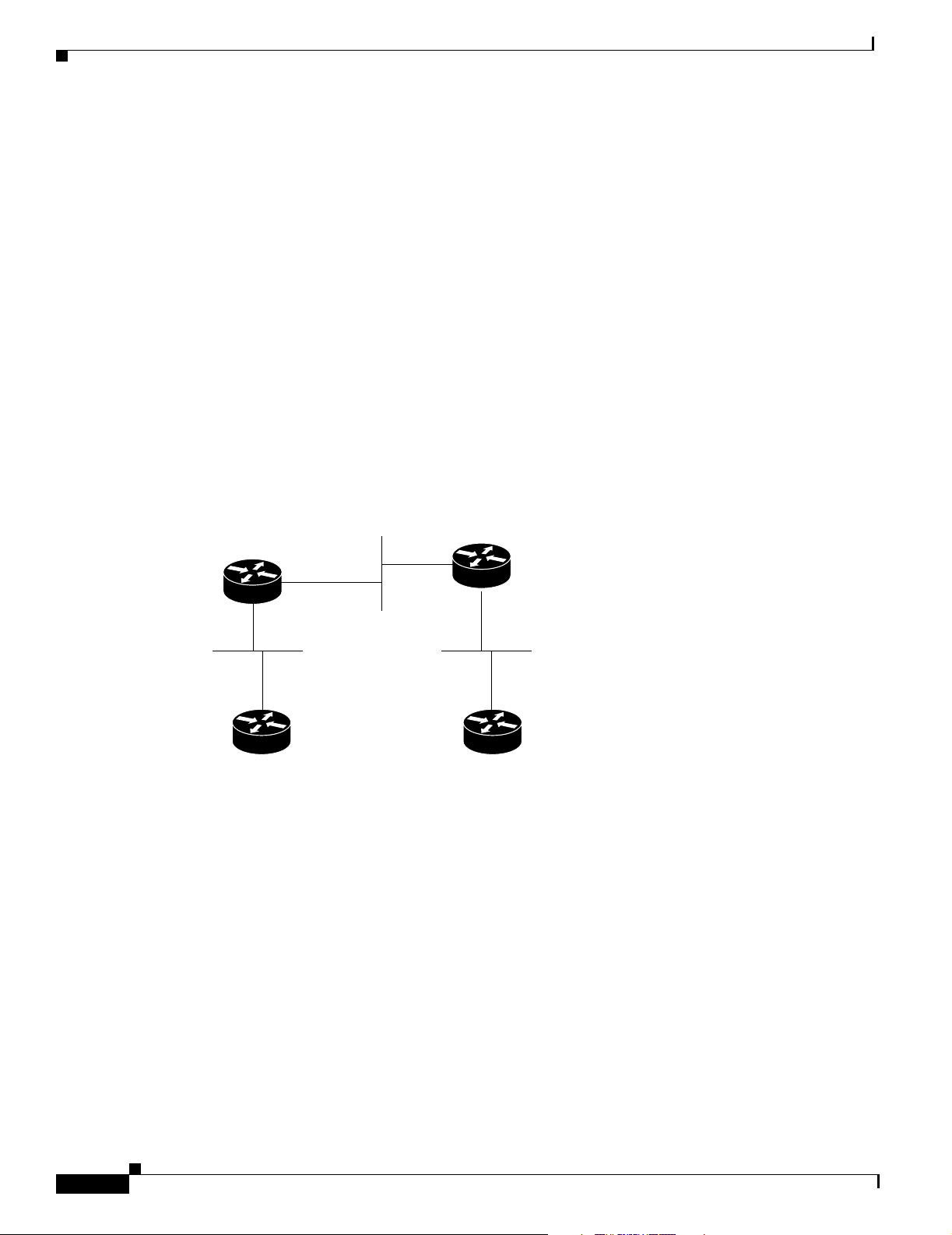
IP Addressing Examples
• Changing the Rate for Triggering SVCs Example
• Applying NHRP Rates to Specific Destinations Example
• NHRP on a Multipoint Tunnel Example
• Broadcasting Examples
• NAT Configuration Examples
• ping Command Example
Creating a Network from Separated Subnets Example
In the following example, subnets 1 and 2 of network 131.108.0.0 are separated by a backbone, as shown
in Figure 8. The two networks are brought into the same logical network through the use of secondary
addresses.
Figure 8 Creating a Network from Separated Subnets
Network 192.5.10.0
Subnet 172.16.3.0
Configuring IP Addressing
Router B
E2
Subnet 172.16.1.0 Subnet 172.16.2.0
Router A
Router C
E1
Router D
S1016a
The following examples show the configurations for routers B and C:
Router B Configuration
interface ethernet 2
ip address 192.5.10.1 255.255.255.0
ip address 131.108.3.1 255.255.255.0 secondary
Router C Configuration
interface ethernet 1
ip address 192.5.10.2 255.255.255.0
ip address 131.108.3.2 255.255.255.0 secondary
Serial Interfaces Configuration Example
In the following example, the second serial interface (serial 1) is given the address of Ethernet interface
0. The serial interface is unnumbered.
interface ethernet 0
Cisco IOS IP Configuration Guide
IPC-50
Page 97

Configuring IP Addressing
ip address 145.22.4.67 255.255.255.0
interface serial 1
ip unnumbered ethernet 0
IP Domains Example
The following example establishes a domain list with several alternate domain names:
ip domain list csi.com
ip domain list telecomprog.edu
ip domain-list merit.edu
Dynamic Lookup Example
A cache of host name-to-address mappings is used by connect, telnet, ping, trace, write net, and
configure net EXEC commands to speed the process of converting names to addresses. The commands
used in this example specify the form of dynamic name lookup to be used. Static name lookup also can
be configured.
IP Addressing Examples
The following example configures the host name-to-address mapping process. IP DNS-based translation
is specified, the addresses of the name servers are specified, and the default domain name is given.
! IP Domain Name System (DNS)-based host name-to-address translation is enabled
ip domain lookup
! Specifies host 131.108.1.111 as the primary name server and host 131.108.1.2
! as the secondary server
ip name-server 131.108.1.111 131.108.1.2
! Defines cisco.com as the default domain name the router uses to complete
! unqualified host names
ip domain name cisco.com
HP Hosts on a Network Segment Example
The following example has a network segment with HP devices on it. The commands in this example
customize the first Ethernet port to respond to Probe name requests for the host name, and to use Probe
and ARP.
ip hp-host bl4zip 131.24.6.27
interface ethernet 0
arp probe
ip probe proxy
Logical NBMA Example
A logical NBMA network is considered the group of interfaces and hosts participating in NHRP and
having the same network identifier. Figure 9 illustrates two logical NBMA networks (shown as circles)
configured over a single physical NBMA network. Router A can communicate with routers B and C
because they share the same network identifier (2). Router C can also communicate with routers D and
E because they share network identifier 7. After address resolution is complete, router A can send IP
packets to router C in one hop, and router C can send them to router E in one hop, as shown by the dotted
lines.
Cisco IOS IP Configuration Guide
IPC-51
Page 98

IP Addressing Examples
Configuring IP Addressing
Figure 9 Two Logical NBMA Networks over One Physical NBMA Network
Destination
host
ip nhrp network-id 7
Router E
ip nhrp network-id 7
ip nhrp network-id 2
ip nhrp
network-id 2
Source
host
= Statically configured tunnel endpoints or permanent virtual circuits
= Dynamically created virtual circuits
Router A
Router C
Router B
ip nhrp network-id 2
Router D
ip nhrp network-id 7
S3230
The physical configuration of the five routers in Figure 9 might actually be that shown in Figure 10. The
source host is connected to Router A and the destination host is connected to Router E. The same switch
serves all five routers, making one physical NBMA network.
IPC-52
Cisco IOS IP Configuration Guide
Page 99

Configuring IP Addressing
IP Addressing Examples
Figure 10 Physical Configuration of a Sample NBMA Network
Source
host
Router A
Router E
Destination
host
Router B
Router C
Router D
S3231
Refer again to Figure 9. Initially, before NHRP has resolved any NBMA addresses, IP packets from the
source host to the destination host travel through all five routers connected to the switch before reaching
the destination. When Router A first forwards the IP packet toward the destination host, Router A also
generates an NHRP request for the IP address of the destination host. The request is forwarded to
Router C, whereupon a reply is generated. Router C replies because it is the egress router between the
two logical NBMA networks.
Similarly, Router C generates an NHRP request of its own, to which Router E replies. In this example,
subsequent IP traffic between the source and the destination still requires two hops to traverse the NBMA
network, because the IP traffic must be forwarded between the two logical NBMA networks. Only one
hop would be required if the NBMA network were not logically divided.
NHRP over ATM Example
The following example shows a configuration of three routers using NHRP over ATM. Subinterfaces and
dynamic routing also are used. Router A obtains an OSPF route that it can use to reach the LIS where
Router B resides. Router A can then initially reach Router B through Router C. Router A and Router B
are able to directly communicate without Router C once NHRP has resolved the respective NSAP
addresses of Router A and Router C.
Cisco IOS IP Configuration Guide
IPC-53
Page 100

IP Addressing Examples
Configuring IP Addressing
The significant portions of the configurations for routers A, B, and C follow:
Router A Configuration
interface ATM0/0
ip address 10.1.0.1 255.255.0.0
ip nhrp network-id 1
map-group a
atm nsap-address 11.1111.11.111111.1111.1111.1111.1111.1111.1111.11
atm rate-queue 1 10
atm pvc 1 0 5 qsaal
router ospf 1
network 10.0.0.0 0.255.255.255 area 0
map-list a
ip 10.1.0.3 atm-nsap 33.3333.33.333333.3333.3333.3333.3333.3333.3333.33
Router B Configuration
interface ATM0/0
ip address 10.2.0.2 255.255.0.0
ip nhrp network-id 1
map-group a
atm nsap-address 22.2222.22.222222.2222.2222.2222.2222.2222.2222.22
atm rate-queue 1 10
atm pvc 2 0 5 qsaal
router ospf 1
network 10.0.0.0 0.255.255.255 area 0
map-list a
ip 10.2.0.3 atm-nsap 33.3333.33.333333.3333.3333.3333.3333.3333.3333.33
Router C Configuration
interface ATM0/0
no ip address
atm rate-queue 1 10
atm pvc 2 0 5 qsaal
interface ATM0/0.1 multipoint
ip address 10.1.0.3 255.255.0.0
ip nhrp network-id 1
map-group a
atm nsap-address 33.3333.33.333333.3333.3333.3333.3333.3333.3333.33
atm rate-queue 1 10
interface ATM0/0.2 multipoint
ip address 10.2.0.3 255.255.0.0
ip nhrp network-id 1
map-group b
atm nsap-address 33.3333.33.333333.3333.3333.3333.3333.3333.3333.33
atm rate-queue 1 10
router ospf 1
network 10.0.0.0 0.255.255.255 area 0
neighbor 10.1.0.1 priority 1
neighbor 10.2.0.2 priority 1
IPC-54
Cisco IOS IP Configuration Guide
 Loading...