

Page 1
CHAPTER
3
Installing the Chassis
This chapter describes how to install and test the Cisco Metro 1500 series system
chassis. The equipment is installed during normal working hours. It is usually
connected to active CPU channels or control units after working hours.
This chapter includes the following sections:
• Before Installing, page 3-1
• Installing the System, page 3-4
• Connecting Power, page 3-8
• Cleaning the System, page 3-18
• Removing the Power Supply Module, page 3-21
• Running Online Tests, page 3-25
• Troubleshooting, page 3-28
Before Installing
Before you install the system, you must complete the following tasks:
• Unpacking and Inspecting the System
• Maintaining a Network Record
• Mounting the System
78-10588-03
Cisco Metro 1500 Series Hardware Installation Guide
3-1
Page 2
Before Installing
Caution Use extreme care when removing or installing connectors so you do
not damage the connector housing or scratch the end-face surfaceof
the fiber. Alwaysinstall protective covers on unused or disconnected
components to prevent contamination. Always clean fiber
connectors before installing them.
Unpacking and Inspecting the System
The Cisco Metro 1500 series system comes with the following standard items:
• Cisco Metro 1500 series hardware
• Substitute power-on key (AC powered version only)
• Mounting set
–
19-in. adapter
–
rack screw
–
washers
• Two power cords for each chassis delivered
• Acrylic cover
• Cisco Metro 1500 Series Hardware Installation Guide
• Cisco Metro 1500 Series Software Configuration Guide
• Release Notes for the Cisco Metro 1500 Series
Chapter 3 Installing the Chassis
3-2
Note The systems are used in pairs. Depending on your order, a total
system package can consist of multiple boxes. All boxes are labeled
with a summary of contents, and they are signed and verified by a
packager.If an order includes more than one box, this summary will
show the number of boxes shipped.
The Cisco Metro 1500 series system is thoroughly inspected before shipment. If
any damage has occurred during transportation or if any item is missing, notify
your Cisco customer service representative immediately.
Cisco Metro 1500 Series Hardware Installation Guide
78-10588-03
Page 3

Chapter 3 Installing the Chassis
Upon receipt, inspect the equipment as follows:
Step 1 Take inventory.
Compare the equipment inside with the packing slip and the equipment list
provided by customer service. If there are any discrepancies, notify the Customer
Service Center.
Step 2 Check for external damage.
Visually check all components and immediately report any shipping damage to
your customer service representative. Have the following information ready:
• Invoice number of shipper (see packing slip)
• Model and serial number of the damaged unit
• Description of damage
• Effect of damage on the installation
Before Installing
Maintaining a Network Record
Fill out all the required information in Appendix E, “Unit Maintenance and
Network Record,”so you will have a record of all of your hardware, configuration
options, and network settings.
Mounting the System
The unit is designed for rack-mounting in a cabinet. We recommend mounting up
to four units in one vertical rack and using chassis runners or telescopic slides.
Use star-type lock washers on the rack screws to ensure a good conductive
connection between the unit and the rack. For further information about installing
the units in a customer cabinet, see the instructions from the
cabinet manufacturer.
78-10588-03
Cisco Metro 1500 Series Hardware Installation Guide
3-3
Page 4
Installing the System
Caution Because of rack mounting, the plugs of the power cables on the rear
side of the unit might not be accessible. Please provide a power
circuit breaker to allow front power access. If you do not use a power
circuit breaker, ensure quick access to the plug-socket combinations
on the rear side of the unit at all times. In this case they serve as the
main means of disconnecting.
Installing the System
Chapter 3 Installing the Chassis
Warning
Only trained and qualifiedpersonnel should be allowed to install,
replace, or service this equipment.
To install, connect, and test the system, follow these steps:
Step 1 Unpack and inspect each unit. Verify completeness against the packing list.
Step 2 Fill out the form in Appendix E, “Unit Maintenance and Network Record.”
Step 3 Mount each unit in a cabinet or a rack.
Step 4 Power up each unit.
Step 5 Run online tests as described in the “Running Online Tests” section on page 3-25.
Step 6 Connect the fiber-optic link between sites using the remote channel.
Step 7 Connect applications using the local channels.
Step 8 Test the system online to verify operation.
Note If a network element management interface (NEMI) is not installed,
you have completed this portion of the installation tasks. If a NEMI
is installed, refer to the Cisco Metro 1500 Series Software
Configuration Guide and continue with Step 9.
Step 9 Connect to the serial port.
3-4
Cisco Metro 1500 Series Hardware Installation Guide
78-10588-03
Page 5
Chapter 3 Installing the Chassis
Step 10 Change default passwords. See Appendix E, “Unit Maintenance and Network
Record.”
Step 11 Log in as root and define network settings. See Appendix E, “Unit Maintenance
and Network Record.”
Step 12 Change the SNMP configuration.
Step 13 Reboot the unit.
Installing the NEMI Module
To install a NEMI module (master and slave, as applicable), follow these steps:
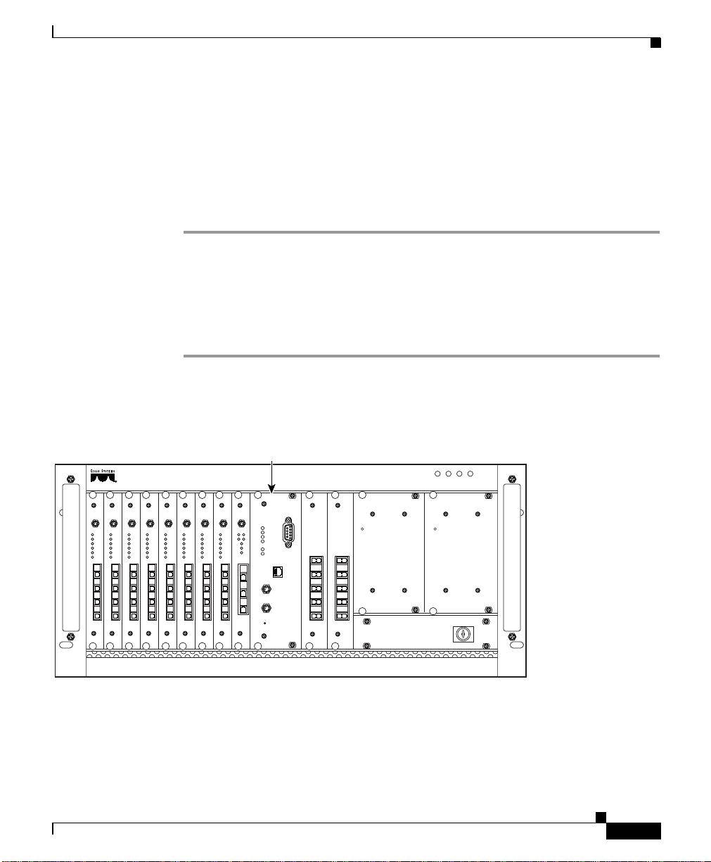
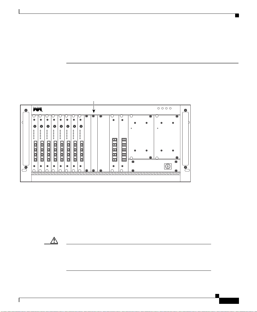
Step 1 Remove the acrylic front cover from the unit in which the module should be
added. (See Figure 3-1.)
Figure 3-1 NEMI Placement in the Primary Chassis and Extension Chassis B.
Installing the System
On/Err
Loop
L/R
L/T
R/R
R/T
L/R
L/R
L/T
L/T
R/R
R/R
R/T
R/T
78-10588-03
NEMI master
OK FAIL
METRO 1500 SERIES
Serial
Power
On/Err
On/Err
On/Err
On/Err
On/Err
On/Err
Loop
Loop
Loop
L/R
L/T
R/R
R/T
L/R
L/T
R/R
R/T
Loop
L/R
L/R
L/R
L/T
L/T
L/T
R/R
R/R
R/R
R/T
R/T
R/T
L/R
L/R
L/R
L/T
L/T
L/T
R/R
R/R
R/R
R/T
R/T
R/T
On/Err
Loop
Loop
Loop
L/R
L/R
L/R
L/T
L/T
L/T
R/R
R/R
R/R
R/T
R/T
R/T
L/R
L/R
L/T
L/T
R/R
R/R
R/T
R/T
OnAL
A/T
A/R
B/T
B/R
T
R
Error
K
Err.Int.BUS
B
Err.Ext.BUS
LKA
LKB
Receive
Auto
Link
MUX
Ch.1-8
Ch.1-8
T/E
Net
BUS 1
BUS 2
2/E
7/8
7/8
5/6
5/6
3/4
3/4
1/2
1/2
110/220V AC
DMX
Power Power
POWER FAN
110/220V AC
OK FAIL
32262
Step 2 Remove the two screws from the blank filler module. Remove the blank filler
panels.
Step 3 Take the new module from the shipping container and use canned, dry, oil-free,
compressed air to blow off any possible dust particles.
Cisco Metro 1500 Series Hardware Installation Guide
3-5
Page 6
Installing the System
Step 4 Insert the NEMI module carefully into the chassis slot while guiding the upper
Caution It is critical to insert the module gently. If you need a force greater
Step 5 Hold the module in position after making full contact and use the two screws on
Step 6 Reset the NEMI modules (both master and slave, if applicable) by inserting a
Step 7 Save the blank filler panels with the packaging material.
Chapter 3 Installing the Chassis
and lower edges of the module in the tracks until its connectors come into contact
with the backplane connectors.
than 1 lb (4.5 newton) to push in the module, stop immediately.
Inspect the electrical connector. If the connector is not damaged,
repeat Step 4.
the front panel of the module to secure it in the housing. When the module is in
contact with the backplane, the green power LED is on.
pointed tool into the small hole on the front panel within the first 30 seconds of
installation. The green power LED comes on and the NEMI module starts up.
3-6
Cisco Metro 1500 Series Hardware Installation Guide
78-10588-03
Page 7
Chapter 3 Installing the Chassis
Installing the DEMI Module
To install a DEMI module, follow these steps:
Step 1 Remove the acrylic front cover from the unit in which the module should be
added. (See Figure 3-2.)
Figure 3-2 DEMI Placement in Extension Chassis A and C
DEMI location
METRO 1500 SERIES
OK FAIL
POWER FAN
Installing the System
OK FAIL
110/220V AC
MUX
DMX
On/Err
On/Err
On/Err
On/Err
On/Err
On/Err
On/Err
Loop
Loop
Loop
Loop
L/R
L/R
L/T
L/T
R/R
R/R
R/T
R/T
L/R
L/R
L/R
L/T
L/T
L/T
R/R
R/R
R/R
R/T
R/T
R/T
Loop
L/R
L/R
L/R
L/T
L/T
L/T
R/R
R/R
R/R
R/T
R/T
R/T
L/R
L/R
L/R
L/T
L/T
L/T
R/R
R/R
R/R
R/T
R/T
R/T
On/Err
Loop
Loop
Loop
L/R
L/R
L/R
L/T
L/T
L/T
R/R
R/R
R/R
R/T
R/T
R/T
L/R
L/R
L/T
L/T
R/R
R/R
R/T
R/T
Ch.9-16
E
15/16
13/14
11/12
9/10
Power Power
Ch.9-16
E
15/16
13/14
11/12
9/10
110/220V AC
32264
Step 2 Remove the two screws from the blank filler module. Remove the blank filler
panel.
Step 3 Take the new module from the shipping container and use canned, dry, oil-free,
compressed air to blow off any possible dust particles.
Step 4 Insert the DEMI module carefully into the chassis slot while guiding the upper
and lower edges of the module in the tracks until its connectors come into contact
with the backplane connectors.
Caution It is critical to insert the module gently. If you need a force greater
than 1 lb (4.5 newton) to push in the module, stop immediately.
Inspect the electrical connector. If the connector is not damaged,
repeat Step 4.
78-10588-03
Cisco Metro 1500 Series Hardware Installation Guide
3-7
Page 8
Connecting Power
Step 5 Hold the module in position after making full contact and use the two screws on
the front panel of the module to secure it in the housing. When the module is in
contact with the backplane, the green power LED is on.
Step 6 Save the blank filler panels with the packaging material.
Connecting Power
The system is equipped with two power supplies and two power cords. The power
must be turned on by the power keyswitch on the AC-powered version only. The
keyswitch is secured against rotation and the key can be removed in either the on
or off position. A key for powering up the system is provided with each system.
When the power is on, all of the green power supply LEDs should be on for each
power supply module (PSM) and wavelength channel module (WCM). The
display panel provides important system information.
Chapter 3 Installing the Chassis
3-8
Warning
Warning
Caution Please use approved extension cords or a power circuit breaker to
The plug-socket combination must be accessible at all times
because it serves as the main disconnecting device.
This unit might have more than one power cord. To reduce the risk
of electric shock, disconnect the two power supply cords before
servicing the unit.
allow front power access.
Cisco Metro 1500 Series Hardware Installation Guide
78-10588-03
Page 9
Chapter 3 Installing the Chassis
Connecting AC Power
To connect AC power, follow these steps:
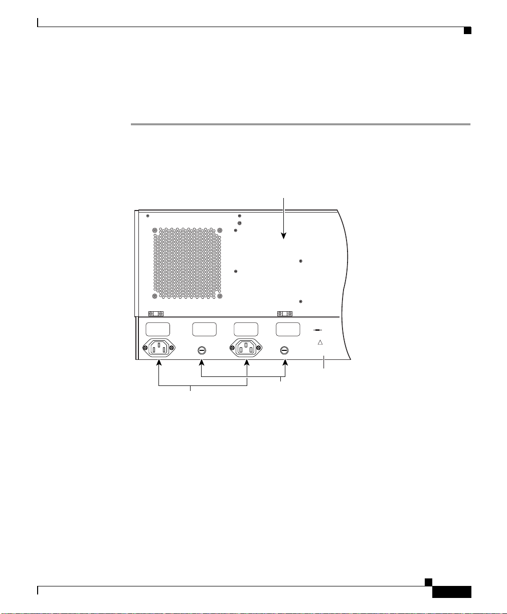
Step 1 Connect the power supply cords to power 1 and power 2 on the rear panel of the
unit. (See Figure 3-3.)
Figure 3-3 Rear Panel of the Cisco Metro 1500 (AC Version)
Connecting Power
Fan module
78-10588-03
115/230 V 50/60 Hz
Voltage:
Max. Current: 2.5 A
Power Consumption
max. 100 W
Fuse: 2
Power 2
Fuse 2 Fuse 1
Power 1
x T 2,5 A / 250 V
For continued protection against risk of fire replace
only with same type and ratings of fuse.
For proper selection of power supply cord refer to
Always remove both
instruction manual.
power cords when dis-
Made in Germany
connecting from power
March 1999
!
source !
Always remove both poewr cords when
disconnecting from a power source.
Instructions for
power supply
50323
AC Power
connectors
Fuse
holders
Step 2 Connect the ends of the power supply cords to the main power supply source.
Step 3 Turn the power on with the keyswitch at the front panel of the unit. (See
Figure 3-4.)
Cisco Metro 1500 Series Hardware Installation Guide
3-9
Page 10

Connecting Power
Figure 3-4 Front Panel of the Cisco Metro 1500
Power
LEDs
Fan
FAIL
OK FAILOK
POWER
LEDs
FAN
PSM1
METRO 1500 SERIES
PSM2
Chapter 3 Installing the Chassis
Serial
Net
MUXM
1-8(32) 1-8(32)
nc
M1
8
8
7
7
6
5
4
3
2
1
D1
7
5
3
1
DMXM
nc
8
6
4
2
Power
on
Power
on
0
I
50322
Keyswitch
(AC version only)
The keyswitch is secured against rotation. The key can be removed in either the
( 0 ) or ( | ) position. A pair of keysfor powering up is supplied with each system.
Warm up the unit for 30 minutes before testing the laser power or connecting
applications.
3-10
Caution If powered down, wait at least 10 seconds before you switch the unit
on again.
Cisco Metro 1500 Series Hardware Installation Guide
78-10588-03
Page 11

Chapter 3 Installing the Chassis
Connecting DC Power
The system is equipped with two PSMs and two DC power cables. There are two
DC powered versions of the Cisco Metro 1500 Series. The European DC version
uses the DC plug-socket conbination. The US version uses terminal blocks.
Depending on the type of connectors on the power distribution unit (PDU), you
have to use the power cables for SELV applications or the power cables for all
other centralized 48-VDC applications.
Installing Terminal Blocks (US Version)
The Cisco Metro 1500 series system is equipped with two PSMs. To connect the
system to the PDU, you need two approved three-core interconnection cables.
To connect the power cables for the US version, follow these steps:
Step 1 Remove the insulation of each wire on both ends of the interconnection cables at
a length of about 5 mm.
Step 2 Connect the wires of the cables to the terminal blocks in the rear panel of the unit.
(See Figure 3-5.)
Connecting Power
78-10588-03
Cisco Metro 1500 Series Hardware Installation Guide
3-11
Page 12

Connecting Power
Figure 3-5 Rear Panel of the PSM (US Version)
Fan module
Voltage:
115/230 V 50/60 Hz
Max. Current: 2.5 A
Power Consumption
max. 100 W
Fuse: 2
Power 2
Fuse 2 Fuse 1
Power 1
x T 2,5 A / 250 V
For continued protection against risk of fire replace
only with same type and ratings of fuse.
For proper selection of power supply cord refer to
Always remove both
instruction manual.
power cords when dis-
Made in Germany
connecting from power
March 1999
!
source !
Always remove both poewr cords when
disconnecting from a power source.
Instructions for
power supply
Terminal blocks
Fuse
holders
Chapter 3 Installing the Chassis
50327
3-12
Caution Do not use damaged terminal blocks. Immediately replace damaged
or defective terminal blocks
Step 3 Take a medium screwdriver and push it into the rectangular hole of the terminal
block. (See Figure 3-6.)At the same time, slide the insulation-free end of the wire
into the respective rectangular hole at the bottom of the power clamp. Repeat this
step for the other wires.
Cisco Metro 1500 Series Hardware Installation Guide
78-10588-03
Page 13

Chapter 3 Installing the Chassis
Figure 3-6 Connecting Wires
Green/yellow wire (ground)
Blue wire (negative)
Brown wire (positive)
Connecting Power
78-10588-03
50328
Step 4 Connect the three wires on the other end to the corresponding high current
connectors of the power distribution unit. Attach the wires to their respective
points in the connectors.
Caution Make sure that the three wires of the power cables are correctly fixed
at the clamps of the PDU connectors.
Caution Never connect blue (negative) or brown (positive) wires to the
ground pin.
Step 5 Turn the power on using the corresponding power switch of the PDU.
Cisco Metro 1500 Series Hardware Installation Guide
3-13
Page 14

Chapter 3 Installing the Chassis
Connecting Power
The chassis powers up as soon as the corresponding power switch of the PDU is
turned on.
Installing the DC Plug-Socket Combination (European Version)
To connect the power cables for the European version, follow these steps:
Step 1 Connect the desired power cables to power 1 and power 2 on the rear panel of the
Cisco Metro 1500 series system and attach the plugs with the screws to the
sockets. (See Figure 3-7.)
Figure 3-7 Rear Panel of the Cisco Metro 1500 (DC Version)
Fan module
3-14
Fuse
holders
Fuse 1 Fuse 2
Power 1 Power 2
DC Power
connectors
Cisco Metro 1500 Series Hardware Installation Guide
115/230 V 50/60 Hz
Voltage:
2.5 A
Max. Current:
max. 100W
Power Consumption:
2x T2.5A / 250V
Fuse:
For continued protection against risk of fire replace
only with same type and ratings of fuse.
For proper selection of power supply cord refer to
instruction manual.
Always remove both
power cords when dis-
Made in Germany
connecting from power
March 1998
!
source 1.
32268
78-10588-03
Page 15

Chapter 3 Installing the Chassis
Caution Tighten the screw of the plug to avoid loss of connection.
Step 2 Choose the appropriate power cable.
Step 3 Connect the plug (the power cable for the SELVapplication is fitted with a special
plug) to the corresponding connector of the PDU. (See Figure 3-8.)
Figure 3-8 SELV Application Power Cable
Connecting Power
78-10588-03
50325
Step 4 Attach the three wires to their respective points in the corresponding connectors
of the PDU as described as follows:
Brown wire life +
Blue wire neutral Green/ Yellow wire ground PE
The power cable for the 48 VDC application has wire ferrules on the other end.
(See Figure 3-9.)
Cisco Metro 1500 Series Hardware Installation Guide
3-15
Page 16

Connecting Power
Figure 3-9 48 VDC Application Power Cable
Blue
Brown
Green/yellow
Ferrules
Chapter 3 Installing the Chassis
3-16
50326
Caution Make sure that the three wires on the power cables are correctly
fixed at the terminal clamps of the unit and at the connectors of the
PDU.
Warning
This warning applies only to units equipped with DC input power
supplies. Wire the DC power supply using the appropriate lugs at
the wiring end. The proper wiring sequence is ground to ground,
positive to positive (line to L), and negative to negative (neutral to
N).Note that the groundwire should alwaysbe connected firstand
disconnected last.
Cisco Metro 1500 Series Hardware Installation Guide
78-10588-03
Page 17

Chapter 3 Installing the Chassis
Step 5 Turn the power on using the corresponding power switch of the PDU.
The chassis powers up as soon as the corresponding power switch of the PDU is
turned on. If the DC power cables are not connected to the PDU, the plug socket
combinations on the rear end of the unit serve as switches.
Power Consumption and Power Supply Fuses
The system power consumption is less than 150 W.
Use the following fuses:
Power Type Fuse Type No. of Fuses
AC version 2.5A at 250V, slow blow, 5 x 20 mm 2
DC version 6.3A at 250V, slow blow, 5 x 20 mm 2
Connecting Power
78-10588-03
Caution Always replace blown fuses with fuses of the same type and size.
Caution Do not use damaged terminal blocks. Immediately replace damaged
or defective terminal blocks.
Note The 115/230V version automatically detects the input voltage. No
further adjustment is necessary.
The Cisco Metro 1500 series system supports the following power sources:
AC 110 to 240V, 50 or 60 Hz
DC -48 to -60V
Cisco Metro 1500 Series Hardware Installation Guide
3-17
Page 18

Cleaning the System
Table 3-1 lists the power requirements in different countries.
Table 3-1 Power Requirements
Region Power Requirements
North America 110 to 120 VAC, 60 Hz or
Europe 210 to 240 VAC, 50 Hz or
Grounding the Chassis
Connecting the power cords to the chassis provides basic grounding. You should
also connect a separate grounding cable for each chassis to the rack. Use the
ground contact on the right side of the chassis to make the grounding connection.
To ground the chassis, follow these steps:
Chapter 3 Installing the Chassis
-48 to -60 VDC
-48 to -60 VDC
Step 1 Connect a wire to the earth contact on the right side of the chassis.
Step 2 Connect the other end of the wire to the rack.
Cleaning the System
This section describes how to clean the chassis and the connectors and includes
the following sections:
• Cleaning the Chassis
• Cleaning the Connectors
Cisco Metro 1500 Series Hardware Installation Guide
3-18
78-10588-03
Page 19

Chapter 3 Installing the Chassis
Cleaning the Chassis
Be very careful with the air flow system when you clean the chassis. If the
cleaning process has to be done while the system is on, be aware that the airflow
system is in operation. Clean the chassis with a damp cloth only and be careful of
the following:
• Do not touch the safety lattice of the airflow system while fans are operating.
• Do not use wet tissues for cleaning the product's outer housing.
• Do not use any harsh or abrasive cleaning agents.
Cleaning the Connectors
Fiber optic connectors are used to connect two fibers together. When these
connectors are used in a communication system, proper connection becomes a
critical factor.
Fiber optic cable connectors can be damaged by improper cleaning and
connection procedures. Dirty or damaged fiber optic connectors can result in not
repeatable or inaccurate communication.
Fiber optic connectors differ from electrical or microwave connectors. In a fiber
optic system, light is transmitted through an extremely small fiber core. Because
fiber cores are often 62.5 microns or less in diameter, and dust particles range
from a tenth of a micron to several microns in diameter, dust and any
contamination at the end of the fiber core can degrade the performance of the
connector interface where the two cores meet. Therefore, the connector must be
precisely aligned and the connector interface must be absolutely free of trapped
foreign material.
Connector,or insertion, loss is a critical performance characteristic of a fiber optic
connector. Return loss is also an important factor. It specifies the amount of
reflectedlight;the lower the reflectionthe better the connection. The best physical
contact connectors have return losses better than -40 dB, although -20 to -30 dB
is more common.
The connection quality depends on two factors; the type of connector and the
proper cleaning and connection techniques.Dirty fiber connectors are a common
source of light loss. Keep the connectors clean at all times and keep the dust cover
installed when not in use.
Cleaning the System
78-10588-03
Cisco Metro 1500 Series Hardware Installation Guide
3-19
Page 20

Cleaning the System
Caution Use extreme care when removing or installing connectors so you do
Step 1 Gently wipe the ferrules and end-face surfaces of the connector with an alcohol
Step 2 Blow dry the connectors with canned, dry, oil-free, compressed air.
Step 3 Use a magnifying glass to inspect the ferrule.
Chapter 3 Installing the Chassis
Before installing any type of cable or connector, use a lint-free alcohol pad from
a cleaning kit to clean the ferrule, the protective white tube around the fiber, and
the end-face surface of the fiber.
As a general rule, whenever there is a significant, unexplained loss of light, clean
the connectors.
not damage the connector housing or scratch the end-face surface of
the fiber.Always install protective covers on unused or disconnected
components to prevent contamination. Always clean fiber
connectors before installing them.
Use a swab saturated with isopropyl alcohol to clean the end-surfaces. Use dry,
oil-free compressed air after applying the isopropyl alcohol.
To clean the optical connectors, follow these steps:
pad from the cleaning kit. Be sure that the pad makes full contact with the
end-face surfaces. Wait five seconds for the surfaces to dry and repeat.
3-20
The connectors used inside the system havebeen cleaned by the manufacturer and
connected to the adapters in the proper manner. The operation of the system
should be error free if the customer provides clean connectors on the application
side, follows the previous directions and ensures the following:
• Clean the connectors using lens tissues before connecting to the adapters. Use
pure alcohol to remove soil.
• Do not clean the inside of the connector adapters.
• Do not use force or quick movements when connecting the fiber optic
connectors in the adapters.
Cisco Metro 1500 Series Hardware Installation Guide
78-10588-03
Page 21

Chapter 3 Installing the Chassis
• Cover the connector adapters to avoid soiling or contaminating the inside of
the adapters while cleaning the chassis.
• Cover the connectors and adapters to avoid the inside of the adapters or the
surface of the connectors from getting dirty when not using the connectors.
Note If the surface is not clean or does not have a uniform shine, repeat
the process using a fresh surface of the alcohol pad.
Removing the Power Supply Module
This section describes how to power on the system, determine whether a power
supply module (PSM) is faulty, and how to replace a PSM, if necessary.
Removing the Power Supply Module
Warning
Power On/Off
Caution If powered off, wait at least 10 seconds before you switch the unit
Only trained and qualifiedpersonnel should be allowed to install,
replace, or service this equipment.
The Cisco Metro 1500 series system has two identical, fully redundant PSMs.
Each PSM can cover the power needs of the entire system. These PSMs provide
5V and 30A to the system. The PSM provides full input-to-output, input-to-case,
and output-to-output isolation.
on again.
Turn the power on or off using the keyswitch on the AC-powered version only.
(See Figure 3-10.) This switch supplies power to the redundant power supplies.
You can only move the switch to the on ( | ) or off ( 0 ) position. Two keys are
shipped with each unit and all units use the same key. You can remove the key in
either the on or off position.
78-10588-03
Cisco Metro 1500 Series Hardware Installation Guide
3-21
Page 22

Removing the Power Supply Module
The display on the front panel of the chassis indicates whether the power is on or
off. You can also monitor power status from the NEMI. For more information
about monitoring the power supply from the NEMI, refer to the
Cisco Metro 1500 series Software Configuration Guide.
Figure 3-10 Power Supply Modules
Chapter 3 Installing the Chassis
MUX
WCM
On/Err
On/Err
On/Err
On/Err
Loop
Loop
L/R
L/R
L/T
L/T
R/R
R/R
R/T
R/T
L/R
L/R
L/R
L/T
L/T
L/T
R/R
R/R
R/R
R/T
R/T
R/T
On/Err
Loop
Loop
Loop
L/R
L/R
L/R
L/T
L/T
L/T
R/R
R/R
R/R
R/T
R/T
R/T
L/R
L/R
L/R
L/T
L/T
L/T
R/R
R/R
R/R
R/T
R/T
R/T
RSM
On/Err
On/Err
Loop
Loop
L/R
L/R
L/T
L/T
R/R
R/R
R/T
R/T
L/R
L/R
L/T
L/T
R/R
R/R
R/T
R/T
NEMI
Serial
L
Power
On/Err
On
k
Error
B
Loop
A
Err.Int.BUS
LA
L/R
k
Err.Ext.BUS
L/T
LB
k
Auto
R/R
Receive
R/T
Link
A/T
A/R
BUS 1
B/T
B/R
BUS 2
M
D
Net
MUX DMX
1-8(32) 1-8(32)
nc
M1
8
8
7
7
6
5
4
3
2
1
DMX
METRO 1500 SERIES
on
nc
D1
8
7
6
5
4
3
2
1
Power 1
Power
Power 2
OK FAILOK
POWER
on
FAIL
FAN
Power
0
I
39943
3-22
Cisco Metro 1500 Series Hardware Installation Guide
78-10588-03
Page 23

Chapter 3 Installing the Chassis
Determining Power Supply Status
If the LED on a power supply is off while the unit is powered on, and the power
cable is plugged in the corresponding power socket, then either the cable is faulty,
a fuse has blown, or the power supply itself has failed. To determine the possible
cause of the failure, follow these steps:
Step 1 Check the power cable to make sure that it is securely plugged into the unit. If the
cable is correctly attached, go to Step 2.
Step 2 Check the fuses by disconnecting the power cord and opening the fuse holder. If
the fuses are okay, swap out the failed power supply module.
Note Check and replace the failed unit as soon as possible.While you
replace the faulty power supply, the redundant power supply
continues to provide uninterrupted service.
Removing the Power Supply Module
78-10588-03
Note The power socket labeled Power 1 supplies current to the left power
supply (Power 1). See Figure 3-11. The power socket labeled
Power 2 supplies current to the right power supply (Power 2).
Cisco Metro 1500 Series Hardware Installation Guide
3-23
Page 24

Removing the Power Supply Module
Figure 3-11 Rear View of Power Supply Module
Fuse
holders
Fuse 1 Fuse 2
Power 1 Power 2
Fan module
Voltage:
Max. Current:
Power Consumption:
Fuse:
For continued protection against risk of fire replace
only with same type and ratings of fuse.
For proper selection of power supply cord refer to
instruction manual.
Made in Germany
March 1998
Chapter 3 Installing the Chassis
115/230 V 50/60 Hz
2.5 A
max. 100W
2x T2.5A / 250V
Always remove both
power cords when disconnecting from power
!
source 1.
32268
3-24
DC Power
connectors
All PSMs are hot-swappable and can be replaced while the system is in service.
To replace a PSM, follow these steps:
Step 1 Remove the power cord associated with the failed power supply and loosen the
four panel screws.
Step 2 Pull out the malfunctioning module.
Step 3 Slide in the spare module.
Step 4 Check that the green LED is on.
Step 5 Reconnect the power cord.
Step 6 Tighten the four panel screws.
Cisco Metro 1500 Series Hardware Installation Guide
78-10588-03
Page 25

Chapter 3 Installing the Chassis
Running Online Tests
Note The power levels cannot be checked without special measurement
equipment because of the automatic laser shutdown (ALS). All
power measurements must be done in-line because of ALS.
System checkout and online testing are usually performed during working hours.
Be sure to coordinate these tasks with the Cisco authorized representative.
Online testing varies from site to site depending on the CPU, operating systems
in use, and the local channels being connected.
Be sure to set up and run your test jobs before installing the unit. Test jobs must
be set up and verifiedby the customer prior to the actual installation of the system.
Fortest purposes, you can force the laser on by means of the network management
system as described in the Cisco Metro 1500 Series Software Configuration
Guide.
Running Online Tests
Note If your test results of the remote link deviate from the results
described in these steps and you cannot correct the problem, contact
your service representative.
Verifying Connections
Although the optical side of the Cisco Metro 1500 series system is designed to be
plug and play, it is common practice to verify input and output levels for the
optical interfaces existing in a typical connection because optical connections are
susceptible to dust and optical cables can be ruined by physical abuse.
Budget measurements should be carried out at points A and F to check whether
the user equipment is correctly interfaced. The budget measurement at point A
should be within the range specified on the Cisco Metro 1500 series label.
Measurement at point E is required to check whether the attenuation over the long
distance is within the power budget. Budget measurements at point C and point
D, measured at the remote side, can be used to calculate loss-levels of the
connecting fiber line. All channel modules leaving the factory are accompanied
by a test report.
78-10588-03
Cisco Metro 1500 Series Hardware Installation Guide
3-25
Page 26

Chapter 3 Installing the Chassis
Running Online Tests
Measuring Channel Outputs and Channel Budgets
Channel module outputs, measured at entry to the MUX, point B, or exit of the
DMX, point E, are practically constant for all channel cards, whereas
measurements at the exit of the BSM (point C) or entry to the BSM (point D) can
exhibit a variation of 0 to 2 dB.
Note All power measurements must be done in-line because of ALS.
All measurements concerning budgets need modulated light. We recommend
using an external modulated light source. Practically any low powered light
source with roughly 100 MHz modulation can be used. If a need for an approved
light source exists, contact your Cisco representative.
You need:
• A Cisco Metro 1500 series system
• Access to two Cisco Metro 1500 series systems under test already connected
through optical fibers and RSMs (or fiber spools) depending on system
configuration
• A short fiber jumper
• Access to ocmstate
• An optical power meter connected in-line through an optical coupler or an
optical in-line power meter
If you have an external 100-MHz modulated light source, follow Steps 1 to 3 to
measure channel output at point F:
3-26
Step 1 Pick a pair of channel modules preferably without clock (or with a clock that can
be disabled with the ocmstate command, since none of the currently delivered
clocks will match).
Step 2 Connect the light source output to the connector labeled L/R (local receiver) of
the local channel module. As a result, the green LED of the local receiver of the
channel module is on and the ALS starts working (every 10 seconds the LED for
remote transmitting blinks shortly). However, the signal does not get looped
back yet.
Cisco Metro 1500 Series Hardware Installation Guide
78-10588-03
Page 27

Chapter 3 Installing the Chassis
Step 3 Use the ocmstate command to switch on the local loop. Now you can measure the
output power at point F. Afterwards, switch off the local loop. To measure at
points B or C, follow Steps 1 and 2 and then Step 4:
Step 4 Use the ocmstate command to switch the remote laser to “forced ON” to overcome
ALS. Then measure at points B and C. If you want to measure the input at points
D or E, follow Steps 1, 2, and 3 and then Step 5.
Step 5 Use ocmstate to activate the remote loopback on the remote side of the link.
The link comes up. All lasers and receivers at the channel module are on and the
remote receiver and the remote transmitter at the channel module on the remote
side of the link are on. The local transmitter at the channel module at the remote
side of the link is also on to allow measurements.
In case you do not have an adequate external modulated light source, you can use
the modulated light (100 MHz) of the pilot laser of the Cisco Metro 1500 series
system’sRSM (only an option if your Cisco Metro 1500 series system is equipped
with an RSM). In this case, in Step 2 you connect the local RSMs B/R (output of
the pilot laser) to the connector labeled L/R (local receiver) of the channel
module. The output of the pilot laser is sent against traffic.
Running Online Tests
78-10588-03
Note Do not forget to set or enable clocks, disable loopback and enable
automatic mode for the RSM before putting the Cisco Metro 1500
series units into service.
Cisco Metro 1500 Series Hardware Installation Guide
3-27
Page 28

Troubleshooting
Troubleshooting
If trouble occurs during installation, check Table 3-2 for a list of troubleshooting
tips. If the solution is not in the table, contact your Cisco service representative.
Table 3-2 Troubleshooting Tips
Problem Probable Cause Solution
No power No power is coming from the
outlet.
Power cables are loose. Check and reseat cables.
Power supply modules are not
engaged.
Power alarm No power is coming from one
outlet.
One power cable is loose. Check and reseat cables.
Power supply fuse is blown. Check and replace fuse.
Not
receiving
local data
Local channel is not online. Place local channel online.
Fiber-optic connectors are loose. Check and reseat connectors.
Tx-Rx connectors are not matched. Switch Tx-Rx connectors.
Connectors are dirty or blown. Clean or replace connectors.
Local cables are not properly
seated.
Local link power exceeds budget. Troubleshoot and retest local link.
Channel card is not connected. Connect all required optical fiber cables to the
Fiber links are dirty or blown. Clean or replace fiber cables.
Turn on power.
Fully engage modules.
Turn on power.
Trace and properly connect cables.
channel card.
Chapter 3 Installing the Chassis
3-28
Cisco Metro 1500 Series Hardware Installation Guide
78-10588-03
Page 29

Chapter 3 Installing the Chassis
Table 3-2 Troubleshooting Tips (continued)
Problem Probable Cause Solution
Not
receiving
remote data
Fiber-optic connectors are loose. Check and reseat connectors.
Tx-Rx connectors are not matched. Switch Tx-Rx connectors.
Remote cables are not properly
Trace and properly connect cable.
seated.
Remote link power exceeds
Troubleshoot and retest remote link.
budget.
Channel card is not connected. Connect all required optical fiber cables to the
channel card.
Fiber links are dirty or blown. Clean or replace fiber cables.
Inactive line
is not in
standby
mode
Link is not connected. Connect all required optical fibercables of the line
to the channel card.
Remote link power exceeds
Troubleshoot and retest remote link.
budget.
Fiber links are dirty or blown. Clean or replace fiber cables.
No password
prompt after
entering a
A non-supported adapter is being
used to connect to the Cisco Metro
1500 series serial port.
Use the supplied DB-9 to RJ-45 adapter or an
adapter that includes DCD/DTR1flow control and
RTS/CTS2 flow control.
proper login
name
1. DCD/DTR = data carrier detect/data terminal ready
2. RTS/CTS = request to send/clear to send
Troubleshooting
78-10588-03
Cisco Metro 1500 Series Hardware Installation Guide
3-29
Page 30

Troubleshooting
Chapter 3 Installing the Chassis
3-30
Cisco Metro 1500 Series Hardware Installation Guide
78-10588-03
 Loading...