

Page 1

Cisco 7500 Series Installation and Configuration Guide
Corporate Headquarters
Cisco Systems, Inc.
170 West Tasman Drive
San Jose, CA 95134-1706
USA
http://www.cisco.com
Tel: 408 526-4000
800 553-NETS (6387)
Fax: 408 526-4100
Customer Order Num b er :
Text Part Number: OL-5008-03 B0
Page 2

THE SPECIFICATIONS AND INFORMATION REGARDING THE PRODUCTS IN THIS M ANUAL ARE SUBJECT TO CHA NGE WITHOUT NO TICE. ALL
STATEMENTS, INFORMATION, AND RECOMMENDATIONS IN THIS MANUAL ARE BELIEVED TO BE ACCURATE BUT ARE PRESENTED WITHOUT
WARRANTY OF ANY KIND, EXPRESS OR IMPLIED. USERS MUST TAKE FULL RESPONSI BILITY FOR THEIR APPLICA TION OF ANY PRODUCT S.
THE SOFTWARE LICENSE AND LIMITED WARRANTY FOR THE ACCOMPANYING PRODUCT ARE SET FORT H IN THE INFORMATION PACKET T HAT
SHIPPED WITH THE PRODUCT AND ARE INCORPORATED HEREIN BY THIS REFERENCE. IF YOU ARE UNABLE TO LOCATE THE SOFTWARE LICENSE
OR LIMITED WARRANTY, CONTACT YOUR CISCO REPRESENTATIVE FOR A COPY.
The following information is for FCC compliance of Class A devices: This equipment has been tested and found to comply with the limits for a Class A digital device, pursuant
to part 15 of the FCC rules. These limits are designed to provide reasonable protection against harmful interference when the equipment is operated in a commercial
environment. This equipment generates, uses, and can radiate radio-frequency energy and, if not installed and used in accor dance with the instruction manual, may cause
harmful interference to radio communications. Operation of this equipment in a residential area is likely to cause harmful interference, in which case users will be required
to correct the interference at their own expense.
The following information is for FCC compliance of Class B devices: The equipment described in this manual generates and may radiate radio-frequency ener gy. If it is not
installed in accordance with Cisco’s installation instructions, it may cause interference with radio and television reception. This equipment has been tested and found to
comply with the limits for a Class B digital device in accordance with the specifications in part 15 of the FCC rules. These specifications are designed to provide reasonable
protection against such interference in a residential installation. However, there is no guarantee that interference will not occur in a particular installation.
Modifying the equipment without Cisc o’s writ ten author ization m ay resul t in the equi pment no lo nger comp lyi ng with FCC requi rements for Class A or Class B digital
devices. In that event, your right to use the equ ipment may be limit ed by FCC regul ations , and you may be requir ed to correct a ny interference to radio or television
communications at your own expense.
You can determine whether your equipment is causing interference by turning it off. If the interferen ce stops, it was probably caused by the Cis co equipm ent or one of its
peripheral devices. If the equipment causes interference to radio or television reception, try to correct the interference by using one or more of the following measures:
• Turn the television or radio antenna unt il the int erference st ops.
• Move the equipment to one side or the other of the televisio n or radi o.
• Move the equipment farther away from the te levision or radio.
• Plug the equipment into an outlet that is on a di fferent cir cuit from the televi sion o r radio. (That is, make certain th e equipment and the te levision or radio are on circuit s
controlled by different circuit breaker s or fuses.)
Modifications to this product no t author ized by Cis co Syst ems, Inc. coul d voi d the FCC appro val and ne gate your authorit y to op erate the pr oduct.
The Cisco implementation of TCP head er compressi on is an adap tation of a program developed by the Universi ty of Ca lifornia, Berk eley (UCB) as part of UCB ’s public
domain version of the UNIX operatin g system. All rights reserved . Copyri ght © 1981 , Rege nts of the Uni versity of Calif ornia.
NOTWITHSTANDING ANY OTHER WARRANTY HEREIN, ALL DOCUMENT FILES AND SOFTWARE OF THE SE SUPPLIERS ARE PROVIDED “AS IS” WITH
ALL FAULTS. CISCO AND THE ABOVE-NAMED SUPPLIERS DISCLAI M ALL WARRANTIE S, EXPRESSED OR IMPLIED, INCLUDING, WITHOUT
LIMITATION, THOSE OF MERCHANTABILITY, FITNESS FOR A PARTICULAR PURPOSE AND NO NINFRINGEM ENT OR ARISING FROM A COURS E OF
DEALING, USAGE, OR TRADE PRACTICE.
IN NO EVENT SHALL CISCO OR ITS SUPPLIERS BE LIABLE FOR ANY INDIRECT, SPECIAL, CONSEQUENTIAL, OR INCIDENTAL DAMAGES, INCLUDING ,
WITHOUT LIMITATION, LOST PROFITS OR LOSS OR DAMAGE TO DATA ARISING OUT OF THE USE OR INABILITY TO USE THIS MANUAL, EVEN IF CISCO
OR ITS SUPPLIERS HAVE BEEN ADVISED OF THE POSSIBILITY OF SUCH DAMAGE S.
CCSP, the Cisco Square Bridge logo, Follow Me Browsing, and StackWise are trademarks of Cisco Systems, Inc.; Changing the Way We Work, Live, Play, and Learn, and iQuick
Study are service marks of Cisco Systems, Inc.; and Access Registrar, Aironet, ASIST, BPX, Catalyst, CCDA, CCDP, CCIE, CCIP, CCNA, CCNP, Cisco, the Cisco Certified
Internetwork Expert logo, Cisco IOS, Cisco Press, Cisco Systems, Cisco Systems Capital, the Cisco Systems logo, Cisco Unity, Empowering the Internet Generation,
Enterprise/Solver, EtherChannel, EtherFast, EtherSwitch, Fast Step, FormShare, GigaDrive, GigaStack, HomeLink, Internet Quotient, IOS, IP/TV, iQ Expertise, the iQ logo, iQ
Net Readiness Scorecard, LightStream, Linksys, MeetingPlace, MGX, the Networkers logo, Networking Academy, Network Registrar, Packet, PIX, Post-Routing, Pre-Routing,
ProConnect, RateMUX, ScriptShare, SlideCast, SMARTnet, StrataView Plus, SwitchProbe, TeleRouter, The Fastest Way to Increase Your Internet Quotient, TransPath, and VCO
are registered trademarks of Cisco Systems, Inc. and/or its affiliates in the United States and certain other countries.
All other trademarks mentioned in this document or Website are the property of their respective owners. The use of the word partner does not imply a partnership relationship
between Cisco and any other company. (0501R)
Cisco 7500 Series Installation and Configu ration Gui de
Copyright © 2005 Cisco Systems, Inc. All rights reserved.
Page 3

Preface xi
Audience xi
Organization xi
Related Documentation xii
Conventions xiii
Safety Warnings xv
Warning Definition xv
Restricted Area Warning xviii
Obtaining Documentation xix
Cisco.com xx
Ordering Documentation xx
Documentation Feedback xx
Obtaining Technical Assistance xx
Cisco Technical Support Website xxi
Submitting a Service Request xxi
Definitions of Service Request Severity xxi
CONTENTS
CHAPTER
Obtaining Additional Publications and Information xxii
1 Cisco 7500 Series Product Overview 1-1
Terms and Acr on y m s 1-2
Cisco 7505 Overview 1-3
Cisco 7505 CyBus Backplane 1-4
Cisco 7505 System Specifications 1-5
Cisco 7507 Overview 1-6
Cisco 7507 Dual CyBus Backplane 1-8
Cisco 7507 System Specifications 1-10
Cisco 7507-MX Overview 1-11
Cisco 7507-MX Dual CyBus Backplane 1-12
Cisco 7507-MX System Specifications 1-14
Cisco 7513 Overview 1-15
Cisco 7513 Dual CyBus Backplane 1-17
Cisco 7513 System Specifications 1-19
Cisco 7513-MX Overview 1-20
OL-5008-03 B0
Cisco 7500 Series Installation and Configuration Guide
iii
Page 4

Contents
Cisco 7513-MX Dual CyBus Backplane 1-22
Cisco 7513-MX System Sp ecifications 1-24
Cisco 7576 Overview 1-25
Cisco 7576 Dual CyBus Backplane 1-27
Identifying Cisco 7576 Independent Routers and CyBuses 1-29
CyBus Slot Number Assignme nts 1-29
Cisco 7576 System Specifications 1-30
Route Switch Processor Overview 1-31
RSP-Specific Hardware Features 1-31
RSP2—Cisco 7505 1-31
RSP4/4+—Cisco7507, Cisco7513, and Cisco7576 1-33
RSP8—Cisco7507-MX and Cisco7513-MX 1-36
RSP16—Cisco 7507, Cisco 7507-MX, Cisco 7513, and Cisco7513-MX 1-39
Common RSP Hardware Features 1-42
RSP LEDs 1-42
RSP DRAM 1-42
RSP SRAM 1-43
RSP NVRAM 1-43
RSP Flash Memory 1-43
RSP EEPROM 1-44
RSP Asynchronous Serial Ports—Console and Auxiliary 1-44
CHAPTER
AC-Input and DC-Input Power Supply Overview 1-46
Arbiter Overview 1-50
Chassis Interface Overview 1-50
Fan Tray and Blower Assembly Overview 1-51
Cisco 7505 Fan Tray Assembly 1-52
Cisco 7507 and Cisco 7507-MX Blower Assembly 1-52
Cisco7513, Cisco 7513-MX, and Cisco7576 Blower Module Assembly 1-53
Interface Processor Overview 1-54
System Software Overview 1-56
2 Preparing for Installation 2-1
Tools and Parts You Ne ed 2-1
Safety Recommendations 2-2
Safety with Electricity 2-2
Chassis Lifting Guidelines 2-3
Preventing Electrostatic Discharge Damage 2-6
AC-Input and DC-Input Power Guidelines 2-7
iv
Cisco 7500 Series Installation and Configuration Guide
OL-5008-03 B0
Page 5

Cisco 7505 Power Considerations 2-7
Cisco 7507 and Cisco 7507-MX Power Considerations 2-8
Cisco 7513, Cisco 7513-MX, and Cisco 7576 Power Considerations 2-9
Plant Wiring Guidelines 2-10
Interference Considerations wit h Cabling 2-10
Distance Limitations of Interface Cabling 2-11
Site Environment, Chassis Temperature, and Airflow Guidelines 2-12
Cisco 7505 Airflow C onsiderations 2-13
Cisco7507 and Cisco 7507-MX Airflow Considerations 2-14
Cisco 7513, Cisco 7513-MX, and Cisco 7576 Airf low Considerations 2-14
Equipment Rack-Moun ting Guidelines 2-15
General Equipment Rack Ventilation Considerations 2-15
Cisco 7505 Rack-Mount Considerations 2-16
Cisco 7507 and Cisco 7507-MX Rack-Mount Considerations 2-18
Cisco 7513, Cisco 7513-MX, and Cisco 7576 Rack-Mount Considerations 2-20
Contents
CHAPTER
Environmental Monitoring and Reporting Overview for the Cisco7500 Series 2-22
Cisco 7500 Series Environmental Monitoring 2-23
Cisco 7500 Series Temperature and Voltage Thresholds 2-24
Cisco 7505 Temperature and Voltage Thresholds 2-24
Cisco 7507 and Cisco 7507-MX Temperature and Voltage Thresholds 2-25
Cisco 7513, Cisco 7513-MX, and Cisco 7576 Temperature and Voltage Thresholds 2-25
Cisco 7500 Series En vironmental Reports 2-26
Cisco 7505 Environmental show Command Examples 2-27
Cisco 7507 and Cisco 7507-MX Environmental show Command Examples 2-29
Cisco7513 and Cisco 7513-MX Environmental show Command Examples 2-31
Cisco7576 Environmental show Command Examples 2-35
3 Installing a Cisco 7500 Series Router 3-1
Cisco 7500 Series Ge neral Installation Consideration s 3-1
Providing a Groun d Connection for the Chassis 3-2
Installing the Cisco 7505 3-4
Cisco 7505 Installation Considerations 3-7
Rack-Mounting the Cisco 750 5 3-7
Attaching th e Ci sco 7505 Cable-Manageme nt Bra ck ets 3-9
Connecting Power t o the Cisco 7505 DC-Inpu t Power Supply 3-9
OL-5008-03 B0
Installing the Cisco 7507 and Cisco 7507-MX 3-11
Cisco 7507 and Cisco 7507-MX Installatio n Considerations 3-14
Installing Cisc o 7507 and Cisco 7507-MX Power Supplies 3-14
Connecting Power t o Cisco 7507 or Cisco 7507-MX DC-Input Power Supplies 3-16
Cisco 7500 Series Installation and Configuration Guide
v
Page 6

Contents
Installing the Ci sco 7513, Cisco 7513-MX, and Cisco 7576 3-19
Cisco 7513, Cisco 7513-MX, and Cisco 7576 Installation Considerations 3-24
Attaching the Cisco 7513, Cisco 7513-MX, and Cisco 7576 Cable-Management Bracket 3-26
Installing Cisc o7513, Cisco 7513-MX, and Cisco 7576 Power Supplies 3-27
Connecting Power to Cisco 7513, Cisco 7513-MX, and Cisco 7576 DC -Input Power Supplies 3-29
Making Cable Connections to the RSP 3-32
Connecting a Consol e Terminal to the RSP 3-32
Connecting to the Auxiliary Port 3-32
Using the Y-Cables for Console and Auxiliary Connections 3-33
What Do I Do Now? 3-33
CHAPTER
4 Performing a Basic Configuration of the System 4-1
Starting the System and Observing Initial Conditions 4-2
Overview of Software Configuration Regi ster Settings at Startup 4-3
Configuring the Software Configuration Register 4-4
Configuratio n Register Bit Meanings 4-5
Changing Configuration Reg ister Settings 4-7
Booting the Cisco 7500 Series Router for the First Time 4-8
Using the Enable Sec ret and the Enable Password 4-8
Recovering a Lost Password 4-9
Configuring the Cisco 7500 Series System 4-11
Performing a Basi c Configuration Using AutoInstall 4-11
Performing a Basic Manual Configuration Using the Setup F acility 4-12
Configuring the Global Parameters 4-12
Configuring Interfaces 4-15
Performing a Basic Configuration Using Configuration Mode 4-18
Checking the Settings 4-19
Saving the Settings to NVRAM and Reviewing Your Configuration 4-19
Implementing Other Configuration Tasks 4-19
vi
What Do I Do Now? 4-20
Using the Flash Memory C ards in the RSPs 4-20
Installing and Remov ing a Flash Memory Card in an RSP 4-20
Formatting a Flash Memory Card 4-24
Copying Files to Flash Memory 4-25
Making a Flash Memory Card Image Bootable 4-25
Enabling Booting from Flash Memory 4-26
Additional Commands Associated with Flash Memory 4-26
Additional Procedures Associated with Flash Memory Cards 4-27
Cisco 7500 Series Installation and Configuration Guide
OL-5008-03 B0
Page 7

Copying a Bootable Image into a Flash Memory Card 4-27
Copying Bootable Images Between Flash Memor y Cards 4-28
Copying Files Betw een RSP Memory and a Flash Memory Card 4-30
Copying a Configuration File from RSP NVRAM to a Flash Memory Card on the RSP 4-30
Copying a Configuration from RSP DRAM to a Flash Memor y Card on the RSP 4-31
Copying a Configuration File from a Flash Me mory Card to RSP NVRAM 4-31
Recovering from Locked Blocks in Flash Memory Cards 4-32
If You Need More Configuration Information 4-32
Contents
CHAPTER
CHAPTER
5 Maintaining Your Cisco 7505 Router 5-1
Tools Required for Maintenance Procedures 5-2
Overview of Maintenance Procedures for the C isco 7505 5-2
Maintenance Procedures for the Cisco 7505 5-3
Removing and Replacing the Cisco7505 Cover Panel 5-3
Removing an d R ep l a cing the Cisco 75 0 5 Fan Tray 5-5
Removing an d R ep l a cing the Cisco 75 0 5 Power Harness Cover 5-7
Removing and Replacing the Cisco 7505 Backplane Cover 5-9
Removing and Replacing the Chassis Interface in the Cisco 7505 5-11
Removing an d R ep l a ci ng the Cisco 750 5 Po w e r Supply 5-13
6 Maintaining Your Cisco 7507 and Cisco 7507-MX Router 6-1
Tools Required for Maintenance Procedures 6-2
Overview of Maintenance Procedures for theCisco7507 and Cisco 7507-MX 6-2
Maintenance Procedures for the Cisco 7507 and
Cisco 7507-MX
6-3
Removing Cisco7507 and Cisco 7507-MX Power Supplies 6-3
Removing an d R ep l a ci ng the Cisco 750 7 an d Cisco 7507-M X Front Chassi s Pa nels 6-6
Cleaning and Replacing the Cisco 7507 and Cisco 7507-MX Air Filter 6-10
Replacing Cisco 7507 and Cisco 7507-MX Int ernal Components 6-11
Removing and Replac ing the Chassis Interface in the Cisco 75 07 and Cisco 7507-MX 6-12
Removing and Replacing the Cisco 7507 and Cisco 7507-MX LED Board 6-13
Removing an d R ep la cing the Cisco 750 7 an d Cisco 7507-M X B lower Assemb ly 6-15
CHAPTER
OL-5008-03 B0
7 Maintaining Your Cisco 75 13, Cisco 7513-MX, and Cisco 7576 Router 7-1
Tools Required for Maintenance Procedures 7-2
Maintenance Procedures for the Cisco7513, Cisco 7513-MX, and Cisco7576 7-2
Removing Cisco7513, Cisco 7513-MX, and Cisco 7576 Power Supplies 7-3
Removing and Replacing the Cisco 7513, Cisco 7513-MX, and Cisco 7576 Card Cage Assembly 7-5
Removing the Card Cage Assembly 7-5
Cisco 7500 Series Installation and Configuration Guide
vii
Page 8

Contents
Exchanging the EEPROM Devices 7-7
Installing the Car d Cage Assembly 7-9
Removing an d R ep la cing the Cisco 75 1 3, Cisco 7513-M X, a nd Ci s c o 75 7 6 Blower Module 7-10
Removing and Replaci ng the Cis co 7513, Cis co 7513-MX, a nd Cisco 757 6 Chassis Cover Panels 7-11
Removing and Replac ing the Cisco7513, Cisco 7513-MX, and Ci sco7576 Backplane Maintenance
Cover
7-13
Removing and Replacing the Chassis Interface in the Cisco7513, Cisco 7513-MX, and
Cisco7576
7-14
CHAPTER
8 Troubleshooting a Cisco 7500 Series Router 8-1
Troubleshooting Overview 8-2
Problem Solving with Cisco 7500 Series Subs ystems 8-3
Troubleshooting Guidelines for the Cisco 7505 8-4
Identifying Cisco 7505 Startup Problems 8-4
Troubleshooting the Cisco 7505 Power Subsystem 8-7
Troubleshooting the Cisco 7505 Cooling Subsystem 8-7
Troubleshooting Guidelines for the Cisco 7507 and
Cisco 7507-MX
8-8
Identifying Cisc o 7507 and Cisco 7507-MX Startup Problems 8-9
Troubleshooting the Cisco 7507 and Cisco 7507-MX Power Subsystem 8-10
Troubleshooting the Cisco 7507 and Cisco 7507-MX Cooling Subsystem 8-11
Troubleshooting Guidelines for the Cisco7513,
Cisco 7513-MX, and Cisco 7576
8-12
Identifying Cisco 7513, Cisco 7513-MX, and Cisco 7576 Startup Problems 8-13
Troubleshooting the Cisco 7513, Cisco 7513-MX, and Cisco 7576 Power Subsystem 8-15
Troubleshooting the Cisco7513, Cisco 7513-MX, and Cisco7576 Cooling Subsys tem 8-16
Troublesho ot in g B lower Operatio n 8-17
viii
Troubleshooting the Cisco7500 Series Processor Subsyst em 8-18
Troubleshooting the RSP 8-18
Troubleshooting the Interface Processors 8-19
Using Cisco 75 0 0 Se ries System LE D s 8-19
Using the Front-P anel System LEDs 8-19
Cisco 7507 and Cisco 7507-MX LEDs 8-20
Cisco 7513, Cisco 7513-MX, and Cisco 7576 LEDs 8-20
Using the RSP LEDs 8-21
RSP2 LEDs—Cisco 7500 Series 8-21
RSP4 and RSP8 LEDs—Cisc o 7500 Series 8-22
Using the Power Supply LEDs 8-23
Cisco 7505 Power Supply LED 8-23
Cisco 7500 Series Installation and Configuration Guide
OL-5008-03 B0
Page 9

Cisco 7507 and Cisco 7507-MX Power Supply LEDs 8-23
Cisco 7513, Cisco 7513-MX, and Cisco 7576 Power Supply LEDs 8-25
Additional Reference Information for Troubleshooting 8-26
Contents
CHAPTER
APPENDIX
9 Replacing DRAM on the Route Switch Processor 9-1
Upgrading or Replacing DRAM SIMMs on the RSP2 9-1
Removing RSP2 SIMMs 9-3
Installing New RSP2 SIMMs 9-4
Upgrading or Replacing DRAM DIMMs on the RSP4 and RSP8 9-5
Removing RSP4 and RSP8 DIMMs 9-9
Installing New RSP4 or RSP8 DIMMs 9-10
A Configuration Register Information A-1
Configuratio n Bit Meanings A-1
Bits 0–3 A-2
Bit 6 A-3
Bit 7 A-3
Bit 8 A-4
Bit 10 and Bit 14 A-4
Bit 11 and Bit 12 A-4
Bit 13 A-4
Bit 15 A-5
I
NDEX
OL-5008-03 B0
Displaying the Configuration Register While Running Cisco IOS A-5
Displaying the Configuration Register While Running ROM Monitor A-5
Setting the Configuration Register While Running Cisco IOS A-6
Setting the Configuration Register Whil e Running ROM Monitor A-6
Cisco 7500 Series Installation and Configuration Guide
ix
Page 10

Contents
Cisco 7500 Series Installation and Configuration Guide
x
OL-5008-03 B0
Page 11

Audience
Preface
This preface descr ibes the audience, or ga nizati on, and conventio ns of this insta llation an d conf iguratio n
guide, and provides i nfor ma tion o n how to ob tai n re lat ed docum en tat ion.
This guide contains specific procedures for the initial hardware installation, and procedures for
performing the basic syste m configurati on of your Cisc o 7500 series rou ter. The Cisco 7500 serie s
includes six router s: t he C is co 7505, Cisco 750 7, Ci sco 7507-MX, Cisco 7513, Cisco 75 13- MX, and
Cisco 7576.
The Cisco 7505 , Cisco 7507, and Cisco 7507-MX route rs ar rive with al l pr oces sor mo dule s i nsta lled ;
however, the Cisco 7513 , Cisco 7513-MX, and Cisc o 7576 routers arrive with p roce ssor mo dule s
individually packaged; yo u need to install these in your syst em. Afte r you install t he hardware and
perform a basic system configuration, you will then use the appropriate software configuration
publications and c om pan ion pub lica tio ns to m ore c om ple tely co nfigure you r syste m and i ts i nte rface s.
Setting up and maintaining a network requires the knowledge and expertise of people with a variety of
skills. In many cases, the people responsible for installing hardware and wiring are not the ones who
configure the software and ad minister the network; there fore, this publ icatio n provides info rmati on
specific to installing the rout er h ardwa re a nd perf or ming a ba sic sys tem configur ation . To use this
publication, you should be familiar with electronic circuitry and wiring practices, and basic network
configuration, and preferably have experience as an electronic or electromechanical technician.
Organization
This guide is organized as follows:
OL-5008-03 B0
Cisco 7500 Series Installation and Configuration Guide
xi
Page 12

Related Documentation
Chapter Title Description
Chapter 1 Cisco 7500 Series Product
Overview
Chapter 2 Preparing for Installation Describes safety considerations, tools required, an
Chapter 3 Installing a Cisco 75 00
Series Router
Chapter 4 Performing a Basic
Configuration of the System
Chapter 5 Maintaining Your Cisco
7505 Router
Chapter 6 Maintaining Your Cisco
7507 and Cisco 7507-MX
Router
Chapter 7 Maintaining Your Cisco
7513, Cisco 7 513-M X, a nd
Cisco 7576 Route r
Chapter 8 Troubleshooting a Cisco
7500 Series Route r
Chapter 9 Replacing DRAM on the
Route Switch Processor
Appendix A Configuration Register
Information
Describes the physical prope rties of each of the Cisco
7500 series routers. T he rem ain ing sect ions of this
chapter describe router components, which are
considered to be standard equipment and ship with each
router.
overview of the installation, and pr oced ure s you shou ld
perform before the actual installation of your Cisco 7500
series router.
Provides information for installing the router hardware.
The chapter includes a section describing generic
installation requirements; it also includes additional
sections for each Ci sco 750 0 seri es r oute r.
Provides simple procedures for completing a basic
system configuration of your Cisco 7500 series router,
and for checking and saving this configuration to system
memory.
Describes th e procedures required to perform routine
maintenance an d to remo ve an d replace f ield- replace able
units (FRUs) in your Cisco 7505 r oute r.
Describes th e procedures required to perform routine
maintenance an d to remo ve an d replace f ield- replace able
units (FRUs) in your Cisco 7507 and Ci sco 7 507 -MX
router.
Describes th e procedures required to perform routine
maintenance an d to remo ve an d replace f ield- replace able
units (FRUs) in your Cisco 7513 , Cisco 75 13- MX, a nd
Cisco 7576 router.
Describes basic troub leshoot ing guid eline s, shoul d you
have difficulty with your Cisco 75 00 ser i es ro ut er
installation.
Describes the procedures required to upgrade the
dynamic random-access memory (DRAM) devices on the
RSPs in your Cisco 7500 series routers.
Provides conf iguration re gister in formation for the Cisco
7500 Series routers.
Preface
Related Documentation
Use the Cisco 7500 Series Routers Documentation Roadmap to access the appropriate installation and
configuration guide fo r your speci fic interface pro cessor. Information is available online or on the
Documentation CD-R OM. Use this infor mation in con junction with t he procedures d escribed in Chapter
4, “Performing a B asic C onfiguration of the System ,” to configure the interface processors in your
router.
Cisco 7500 Series Installation and Configuration Guide
xii
OL-5008-03 B0
Page 13

Preface
Conventions
For comprehensive descriptions and examples of software configuration commands and the procedures
for implementing them, refer to the related software configuration and reference documentation listed in
the “If You Need More Configuration Information” section on page 4-32 and to the Cisco IOS software
release note specific to the release of Cisco IOS softwa re you are ru nning on your system.
For a complete list of related documentation, refer to the Cisco 7500 Series Routers Documentation
Roadmap. Y our router also sh ips with one of th e follo wing Quic k Start Guides, along with the safety an d
compliance documents listed below:
• Cisco 7505 Router Qui ck Start Gui de (D OC-78129 49=)
• Cisco 7507 Router Qui ck Start Gui de (D OC-78130 34=)
• Cisco 7513 and 7576 Routers Quick Start Guide (DOC- 7812954 =)
• Regulatory Compliance and Safety Info rmation for th e Cisco 7500 Se ries Rout ers(D OC- 784194= )
Cisco 7500 series ro u ter s inc lud e ma ny different field-rep lacable units (FRUs), such as power supplies,
rack-mount kits, route switch processors, interface processors, versatile inteface processors, port
adapters, an d so fo rth. The d oc um entat ion fl yer inc lu des links t o these docum en ts .
Information is available online, on the D ocumenta tion CD -ROM, or as printed copies .
Conventions
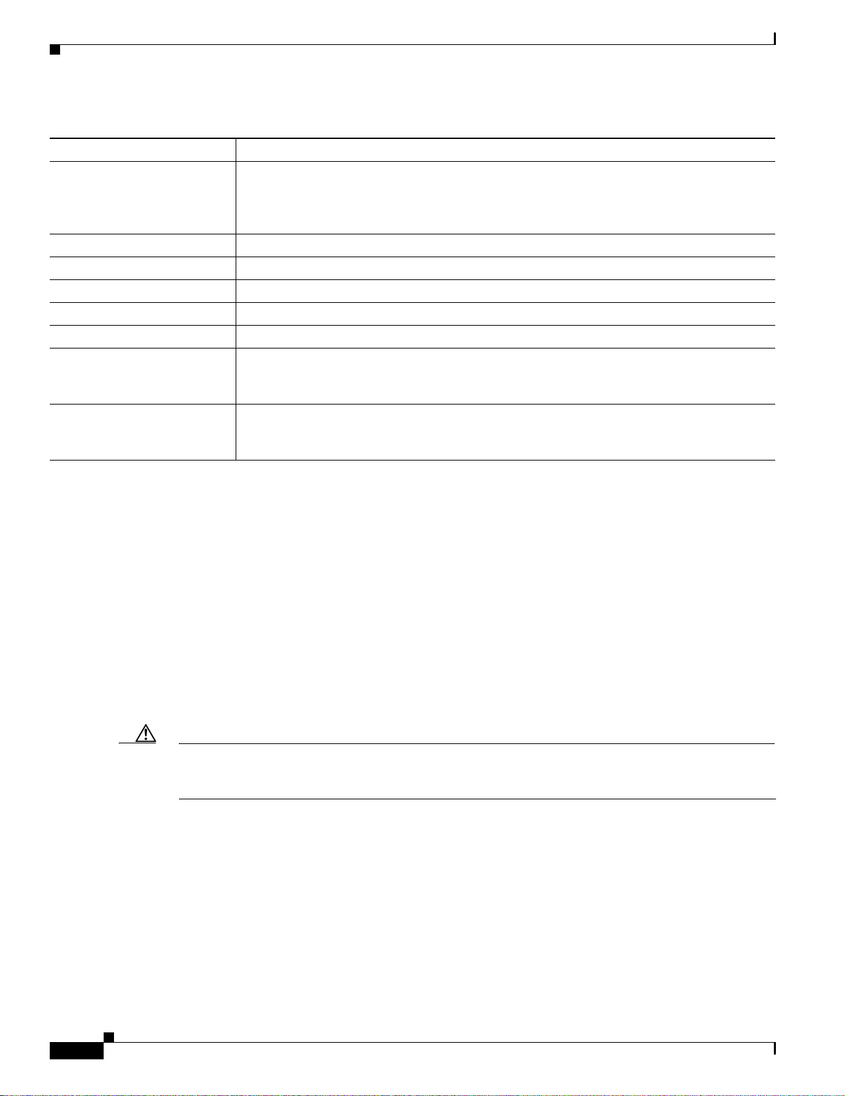
This document uses the conventions listed in Table 1:
Table 1 Conventions
Convention Description
boldface font Commands and keywords a re i n boldface.
italic font Arguments for whi ch y ou supp ly values are in italics.
[ ] Elements in square brackets are optional.
{ x | y | z } Alternative keywords are groupe d in br ace s a nd separ ate d by verti cal
bars.
[ x | y | z ] Optional alternat ive keywords are grouped in brackets an d separ ated
by vert i cal bars.
string A nonquoted set of characters. Do not use quotation marks around the
string or the string will include the quotation marks.
screen font Terminal sessions and information the system displays are in screen
font.
boldface screen font I nformat ion you must enter is in bol dface scre en font .
italic screen font Arguments for whi ch y ou supp ly value s are i n i talic scre en font .
This pointer highlights an important line of text in an
example.
^ The symbol ^ represents the key labeled Control—for example, the
key combination ^D in a screen display means hold down the Control
key while you press the D key.
< > Nonprinting characters, such as passwords, are in angle brackets.
OL-5008-03 B0
Notes use the following conventions:
Cisco 7500 Series Installation and Configuration Guide
xiii
Page 14
Conventions
Note Means reader take note. Notes contain helpful suggestio ns or references to material not covered in the
publication.
Timesavers use the following conventions:
Timesaver Means the described action saves time. You can save time by performing the action described in the
paragraph.
Tips use the following conventions :
Tip Means the following are useful tips.
Cautions use the following conventions:
Caution Means reader be careful. In this situation, you might do som ething th at coul d result in eq uipment
damage or loss of data.
Preface
Warning
Warn ings use the foll owing conventions:
Safety warnings appear throughout this publication in procedures that, if performed incorrectly, may
harm you. A warning symbol precedes each warning statement.
xiv
Cisco 7500 Series Installation and Configuration Guide
OL-5008-03 B0
Page 15

Preface
Safety Warnings
Warning Definition
Safety Warnings
Warning
Waarschuwing
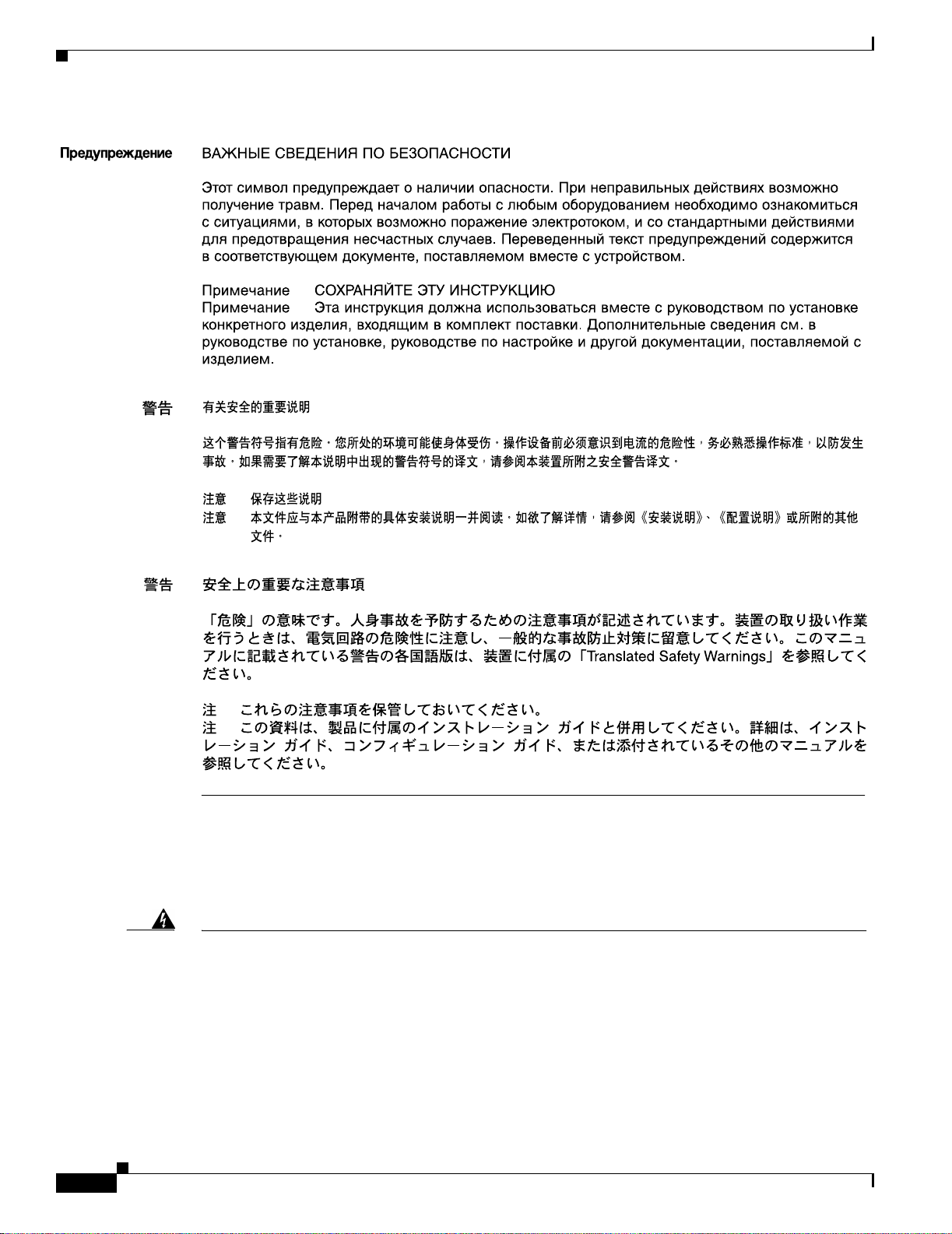
IMPORTANT SAFETY INSTRUCTIONS
This warning symbol means danger. You are in a situation that could cause bodily injury. Before you
work on any equipment, be aware of the hazards involved with electrical circuitry and be familiar
with standard practices for preventing accidents. To see translations of the warnings that appear in
this publication, refer to the translated safety warnings that accompanied this device.
Note: SAVE THESE INSTRUCTIONS
Note: This documentation is to be used in conjunction with t he specific product instal lat ion guide
that shipped with the product. Please refer to the Installation Guide, Configuration Guide, or other
enclosed additional documentation for further details.
BELANGRIJKE VEILIGHEIDSINS TRUC TIE S
Dit waarschuwingssymbool betekent gevaar. U verkeert in een situatie die lichamelijk letsel kan
veroorzaken. Voordat u aan enige apparatuur gaat werken, dient u zich bewust te zijn van de bij
elektrische schakelingen betrokken risico's en dient u op de hoogte te zijn van de standaard
praktijken om ongelukken te voorkomen. Voor een vertaling van de waarschuwingen die in deze
publicatie verschijnen, dient u de vertaalde veiligheidswaarschuwingen te raadplegen die bij dit
apparaat worden geleverd.
Opmerking B EWAAR DEZE INSTRUCTIES.
Opmerking D eze documentatie dient gebruikt te worden in combinatie met de
installatiehandleiding voor het specifieke product die bij het product wordt geleverd. Raadpleeg de
installatiehandleiding, configuratiehandleiding of andere verdere ingesloten documentatie voor
meer informatie.
Varoitus
OL-5008-03 B0
TÄRKEITÄ TURVALLISUUTEEN LIITTYVIÄ OHJEITA
Tämä varoitusmerkki merkitsee vaaraa. Olet tilanteessa, joka voi johtaa ruumiinvammaan. Ennen
kuin työskentelet minkään laitteiston parissa, ota selvää sähkökytkentöihin liittyvist ä vaaroista ja
tavanomaisista onnettomuuksien ehkäisykeinoista. Tässä asiakirjassa esitettyjen varoitusten
käännökset löydät laitteen mukana toimitetuista ohjeista.
Huomautus SÄILYTÄ NÄMÄ OHJEET
Huomautus Tämä asiakirja on tarkoitettu käytettäväksi yhdessä tuotteen mukana tulleen
asennusoppaan kanssa. Katso lisätietoja asennusoppaasta, kokoonpano-oppaasta ja muista
mukana toimitetuista asiakirjoista.
Cisco 7500 Series Installation and Configuration Guide
xv
Page 16

Safety Warnings
Preface
Attention
Warnung
IMPORTANTES INFORMATIONS DE SÉCU RI TÉ
Ce symbole d'avertissement indique un danger . V ous vous trouvez dans un e situation pouvant causer
des blessures ou des dommages corporels. Avant de travailler sur un équipement, soyez cons cient
des dangers posés par les circuits électriques et familiarisez-vous avec les procédures couramment
utilisées pour éviter les accidents. Pour prendre connaissance des traductions d'avertissements
figurant dans cette publication, consultez les consignes de sécurité traduites qui accompagnent cet
appareil.
Remarque CONSERVEZ CES INFORMATIONS
Remarque Cett e documentation doit être utilisée avec le guide spécifique d'installati on du produit
qui accompagne ce dernier. Veuillez vous reporter au Guide d'installation, au Guide de
configuration, ou à toute autre documentation jointe pour de plus amples renseignements.
WICHTIGE SI CHERHE ITSAN WEIS UNGEN
Dieses Warnsymbol bedeutet Gefahr. Sie befinden sich in einer Situation, die zu einer
Körperverletzung führen könnte. Bevor Sie mit der Arbeit an irgendeinem Gerät beginnen, seien Sie
sich der mit elektrischen Stromkreisen verbundenen Gefahren und der Standardpraktiken zur
Vermeidung von Unfällen bewusst. Übersetzungen der in dieser Veröffentlichung enthaltenen
Warnhinweise sind im Lieferumfang des Geräts enthalten.
Hinweis BEWAHREN SIE DIESE SICHERHEITSANWEISUNGEN AUF
Hinweis Dieses Handbuch ist zum Gebrauch in Verbindung mit dem Installationshandbuch für Ihr
Gerät bestimmt, das dem Gerät beiliegt. Entnehmen Sie bitte alle weiteren Informationen dem
Handbuch (Installations- oder Konfigurationshandbuch o. Ä.) für Ihr spezifisches Gerät.
Figyelem!
Avvertenza
FONTOS BIZTONSÁGI ELÕÍRÁSOK
Ez a figyelmezetõ jel veszélyre utal. Sérülésveszélyt rejtõ helyzetben van. Mielõtt bármely
berendezésen munkát végezte, legyen figyelemmel az elektromos áramkörök okozta kockázatokra,
és ismerkedjen meg a szokásos balesetvédelmi eljárásokkal. A kiadványban szereplõ
figyelmeztetések fordítása a készülékhez mellékelt biztonsági figyelmeztetések között található.
Megjegyzés ÕRI ZZE MEG EZEKET AZ UTASÍTÁSOKAT!
Megjegyzés Ezt a dokumentációt a készülékhez mellékelt üzembe helyezési útmutatóval együtt kell
használni. További tudnivalók a mellékelt Üzembe helyezési útmutatóban (Installation Guide),
Konfigurációs útmutatóban (Configuration Guide) vagy más dokumentumban találhatók.
IMPORTANTI ISTRUZIONI SULLA SICUREZZA
Questo simbolo di avvertenza indica un pericolo. La situazione potrebbe causare infortuni alle
persone. Prima di intervenire su qualsiasi apparecchiatura, occorre essere al corrente dei pericoli
relativi ai circuiti elettrici e conoscere le procedure standard per la prevenzione di incidenti. Per le
traduzioni delle avvertenze riportate in questo documento, vedere le avvertenze di sicurezza che
accompagnano questo dispositivo.
Nota CONSERVARE QUESTE ISTRUZIONI
Nota La presente documentazione va usata congiuntamente alla guida di installazione specifica
spedita con il prodotto. Per maggiori informazioni, consultare la Guida all'installazione, la Guida
alla configurazione o altra documentazione acclusa.
xvi
Cisco 7500 Series Installation and Configuration Guide
OL-5008-03 B0
Page 17

Preface
Safety Warnings
Advarsel
Aviso
VIKTIGE SIKKERHETSINSTRUKSJONER
Dette varselssymbolet betyr fare. Du befinner deg i en situasjon som kan forårsake personskade.
Før du utfører arbeid med utstyret, bør du være oppmerksom på farene som er forbundet med
elektriske kretssystemer, og du bør være kjent med vanlig praksis for å unngå ulykker. For å se
oversettelser av advarslene i denne publikasjonen, se de oversatte sikkerhetsvarslene som følger
med denne enheten.
Merk TA VARE PÅ DISSE INSTRUKSJONENE
Merk Denne dokumentasjonen skal brukes i forbindelse med den spesifikke
installasjonsveiledningen som fulgte med produktet. Vennligst se installasjonsveiledningen,
konfigureringsveiledningen eller annen vedlagt tilleggsdokumentasjon for detaljer.
INSTRUÇÕES IMPORTANTES DE SEGURANÇA
Este símbolo de aviso significa perigo. O utilizador encontra-se numa situação que poderá ser
causadora de lesões corporais. Antes de iniciar a utilização de qualquer equipamento, tenha em
atenção os perigos envolvidos no manuseamento de circuitos eléctricos e familiarize-se com as
práticas habituais de prevenção de acidentes. Para ver traduções dos avisos incluídos nesta
publicação, consulte os avisos de segurança traduzidos que acompanham este dispositivo.
Nota GUARDE ESTAS INSTRUÇÕES
Nota Esta documentação destina-se a ser utilizada em conjunto com o manual de instalação
incluído com o produto específico. Consulte o manual de instalação, o manual de configuração ou
outra documentação adicional inclusa, para obter mais informações.
¡Advertencia!
Varning!
INSTRUCCIONES IMPORTANTES DE SEGURIDAD
Este símbolo de aviso indica peligro. Existe riesgo para su integridad física. Antes de manipular
cualquier equipo, considere los riesgos de la corriente eléctrica y familiarícese con los
procedimientos estándar de prevención de accidentes. Vea las traducciones de las advertencias
que acompañan a este dispositivo.
Nota GUARDE ESTAS INSTRUCCIONES
Nota Esta documentación está pensada para ser utilizada con la guía de instalación del producto
que lo acompaña. Si necesita más detalles, consulte la Guía de instalación, la Guía de
configuración o cualquier documentación adicional adjunta.
VIKTIGA SÄKERHETSANVISNINGAR
Denna varningssignal signalerar fara. Du befinner dig i en situation som kan leda till personskada.
Innan du utför arbete på någon utrustning måste du vara medveten om farorna med elkretsar och
känna till vanliga förfaranden för att förebygga olyckor. Se översättningarna av de
varningsmeddelanden som finns i denna publikation, och se de översatta säkerhetsvarningarna som
medföljer denna anordning.
OBS! SPARA DESSA ANVISNINGAR
OBS! Denna dokumentation ska användas i samband med den specifika
produktinstallationshandbok som medföljde produkten. Se installationshandboken,
konfigurationshandboken eller annan bifogad ytterligare dokumentation för närmare detaljer.
OL-5008-03 B0
Cisco 7500 Series Installation and Configuration Guide
xvii
Page 18
Safety Warnings
Preface
Restricted Area Warning
Warning
Waarschuwing
Cisco 7500 Series Installation and Configuration Guide
xviii
This unit is intended for installation in restricted access areas. A restricted access area is where
access can only be gained by service through the use of a special tool, lock and key, or other
means of security, and is controlled by the authority responsible for the location.
Dit toestel is bedoeld voor installatie op plaatsen met beperkte toegang. Een plaats met
beperkte toegang is een plaats waar toegang slechts door servicepersoneel verkregen kan
worden door middel van een speciaal instrument, een slot en sleutel, of een ander
veiligheidsmiddel, en welke beheerd wordt door de overheidsinstantie die
verantwoordelijk is voor de locatie.
OL-5008-03 B0
Page 19

Preface
Obtaining Documentation
Varoitus
Attention
Warnung
Avvertenza
Advarsel
Tämä laite on tarkoitettu asennettavaksi paikkaan, johon pääsy on rajoitettua. Paikka,
johon pääsy on rajoitettua, tarkoittaa paikkaa, johon vain huoltohenkilöstö pääsee jonkin
erikoistyökalun, lukkoon sopivan avaimen tai jonkin muun turvalaitteen avulla ja joka on
paikasta vastuussa olevien toimivaltaisten henkilöiden valvoma.
Cet appareil est à installer dans des zones d'accès réservé. Ces dernières sont des zones
auxquelles seul le personnel de service peut accéder en utilisant un outil spécial, un
mécanisme de verrouillage et une clé, ou tout aut re moyen de sécurité. L 'accès aux zones
de sécurité est sous le contrôle de l'autorité responsable de l'emplacement.
Diese Einheit ist zur Installation in Bereichen mit beschränktem Zutritt vorgesehen. Ein
Bereich mit beschränktem Zutritt ist ein Bereich, zu dem nur Wartungspersonal mit einem
Spezialwerkzeugs, Schloß und Schlüssel oder anderer Sicherheitsvorkehrungen Zugang
hat, und der von dem für die Anlage zuständigen Gremium kontrolliert wird.
Questa unità deve essere installata in un'area ad accesso limitato. Un'area ad accesso
limitato è un'area accessibile solo a personale di assistenza tramite un'attrezzo speciale,
lucchetto, o altri dispositivi di sicurezza, ed è controllata dall'autorità responsabile della
zona.
Denne enheten er laget for installasjon i områder med begrenset adgang. Et område med
begrenset adgang gir kun adgang til servicepersonale som bruker et spesielt verktøy, lås og
nøkkel, eller en annen sikkerhetsanordning, og det kontrolleres av den autoriteten som er
ansvarlig for området.
Aviso
¡Advertencia!
Varning!
Esta unidade foi concebida para instalação em áreas de acesso restrito. Uma área de
acesso restrito é uma área à qual apenas tem acesso o pes soal de serviço autorizado, que
possua uma ferramenta, chave e fechadura especial, ou qualquer outra forma de segurança.
Esta área é controlada pela autoridade responsável pelo local.
Esta unidad ha sido diseñada para instalarse en áreas de acceso restringido. Área de
acceso restringido significa un área a la que solamente tiene acceso el personal de
servicio mediante la utilización de una herramienta especial, cerradura con llave, o algún
otro medio de seguridad, y que está bajo el control de la autoridad responsable del local.
Denna enhet är avsedd för installation i områden med begränsat tillträde. Ett område med
begränsat tillträde får endast tillträdas av servicepersonal med ett speciellt verktyg, lås och
nyckel, eller annan säkerhetsanordning, och kontrolleras av den auktoritet som ansvarar för
området.
Obtaining Documentation
Cisco documentatio n and a dd ition al lite rat ure a r e available on Cisc o.co m. Cisc o al so provide s s everal
ways to obtain technical assista nce an d othe r techni cal re sour ces. Thes e secti ons explain how to obtain
technical information from Cisco Systems.
OL-5008-03 B0
Cisco 7500 Series Installation and Configuration Guide
xix
Page 20

Documentation Feedback
Cisco.com
You can access the most current Cisco documentation at this URL:
http://www.cisco.com/univercd/home/home.h tm
You can access the Cisco website at this URL:
http://www.cisco.com
You can access international Cisco websites at this URL:
http://www.cisco.com/public/countries_languages.shtml
Ordering Documentation
You can find ins truc tio ns for or de ring do cu ment atio n a t t his U RL:
http://www.cisco.com/univercd/cc/td/doc/es_inpck/pdi.htm
You can order Cisco doc umen tation in th ese ways:
• Registered Cisco.com users (Cisco direct customers) can order Cisco product documentation from
the Ordering tool:
http://www.cisco.com/en/US/partner/ordering/index. shtml
Preface
• Nonregistered Cisco.co m u ser s can o rd er docum en tati on th rou gh a l oc al ac count r epre sen tative by
calling Cisco Systems Corporate Headquarters (California, USA) at 408 526-7208 or, elsewhere in
North America, by calling 800 553-NETS (6387).
Documentation Feedback
You can send com ments ab out techni cal docum entat ion to bug-doc@c isco.c om.
You can submit c ommen ts by using the respon se car d (if prese nt) behi nd the front cover of y our
document or by wri ting t o the fo llowing a ddress:
Cisco Systems
Attn: Customer Docume nt Ordering
170 West Tasman Drive
San Jose, CA 95134- 988 3
We appre ciate yo ur co mmen ts.
Obtaining Technical Assistanc e
For all customers, partners, resellers, and distributors who h old valid Cisco serv ice contra cts, Cisco
Technical Support provides 24-hour-a-day, award-winning technic al assist anc e. T he C isco Technical
Support Website on Cisco.com features extensive online support resources. In addition, Cisco Technical
Assistance Center (TAC ) en gi neer s provide t eleph one suppor t. I f y ou do n ot hold a valid Cisc o serv ice
contract, contact your reseller.
xx
Cisco 7500 Series Installation and Configuration Guide
OL-5008-03 B0
Page 21

Preface
Cisco Technical Support Website
The Cisco Technical Support Website provides online docum ents a nd tools fo r tr oub lesho oti ng a nd
resolving technical issues with Cisco products and technologies. The website is available 24 hours a day,
365 days a yea r at thi s UR L:
http://www.cisco.com/techsupport
Access to all tools on the Cisco Technical Support Website requires a Cisco.com user ID and password.
If you have a valid service contract but do not have a user ID or password, you can register at this U R L:
http://tools.cisco.com/RPF/register/register.do
Submitting a Service Request
Using the online TAC Service Req uest Tool is the fastest way to open S3 and S4 service requests. (S3
and S4 service requests are those in which your network is minimally impaired or for which you require
product information. ) After you desc ribe you r situation, the TAC Ser vice Re quest Tool automatically
provides recommended solut ions. If yo ur issue is not resolved usin g the recomm ende d resource s, your
service request will be assigned to a Cisco TAC engineer. The TAC Service Request Tool is located at
this URL:
Obtaining Technical Assistance
http://www.cisco.com/techsupport/servicerequest
For S1 or S2 service requests or if you do not have Internet access, contact the Cisco TAC b y telephone.
(S1 or S2 service requests are t hose in whic h your prod uction net work is down or severely degraded.)
Cisco TAC engine ers ar e assi gned imme diatel y t o S1 a nd S2 ser vice r equ ests to help k eep yo ur b usi ness
operations running smoothly.
To op en a servi ce reque st by telephone , use one of the fo llowing numb ers:
Asia-Pacific: +61 2 8446 7411 (Australia : 1 800 805 227)
EMEA: +32 2 704 55 55
USA: 1 800 553 2447
For a complete list of Cisco TAC contacts, go to this URL:
http://www.cisco.com/techsupport/contacts
Definitions of Service Request Severity
To ensure that all service requests are reported in a standard format, Cisco has established severity
definitions.
Severity 1 (S1)—Your network is “down,” or there is a crit ical impact to your business operatio ns. You
and Cisco will commit all necessary resources around the clock to resolve the situation.
Severity 2 (S2)—Operation of an existing networ k is severely degraded, or signi ficant aspects of your
business operation are negatively affected by inadequate performance of Cisco products. You and Cisco
will commit full-time resources during normal business hours to resolve the situation.
Severity 3 (S3)—Operational performance of your network is impaired, but most business operations
remain functional. You and Cisco will commit resources during normal business hours to restore service
to satisfactory levels.
OL-5008-03 B0
Severity 4 (S4)—You require information or assistance with Cisco product capabilities, installation, or
configuration. There is li ttle or no effect on you r business operations.
Cisco 7500 Series Installation and Configuration Guide
xxi
Page 22

Obtaining Additiona l Publications and Informatio n
Obtaining Additional Publications and Information
Information about Cisco products, technologies, and network solutions is available from various online
and printed sources.
• Cisco Marketplace provides a variety of Cisco books, reference guides, and logo merchandise. Visit
Cisco Marketplace, the company store, at this URL:
http://www.cisco.com/go/marketplace/
• The Cisco Product Catalog describes the networking products offered by Cisco Systems, as well as
ordering and custome r support ser vices. Ac cess the Cisc o Product Ca talog at this URL:
http://cisco.com/univercd/cc/td/doc/pcat/
• Cisco Press publishes a wide range of general networking , training and certif ication titles. Both ne w
and experienced users will benefit from these publications. For current Cisco Press titles and other
information, go to Cisco Press at this URL:
http://www.ciscopress.com
• Pa cket magaz ine is the Ci sco System s techni cal user ma gazine for maximiz ing Intern et an d
networking investments. Each quar ter, Packet delivers coverage of t he l ate st ind ust ry t rend s,
technology breakthrough s, and Cisco product s and soluti ons, as well as networ k deployme nt and
troubleshooting t ips, configu ratio n exa mp les, cust om er c a se studie s, ce rtificat ion an d tr aini n g
information, and links to scores of in-depth online resources. You can access Packe t magazine at this
URL:
http://www.cisco.com/packet
Preface
• iQ Magazine is the quarterly pu bli cat ion fr om C isco System s desig ned t o hel p gr owing comp anies
learn how they can use tec hn ology to i n crea se revenue, stre a mline the ir business , and expand
services. The publication identifies the challenges facing these companies and the technologies to
help solve them, usin g rea l-worl d ca se st ud ies an d business st rategies t o he lp r eade rs make soun d
technology investment decisions. You can access iQ Magazin e at this URL :
http://www.cisco.com/go/iqmagazine
• Internet Protocol Journal is a quarterly journal published by Cisco Systems for engineering
professionals involved in designing, developing, and ope ratin g p ubli c a nd pr ivate internets a nd
intranets. You can access the Internet Protocol Journal at this URL:
http://www.cisco.com/ipj
• Wo rld-cla ss networking training is available from Cisco. You can view current offerings at
this URL:
http://www.cisco.com/en/US/learning/index.html
xxii
Cisco 7500 Series Installation and Configuration Guide
OL-5008-03 B0
Page 23

CHAPTER
1
Cisco 7500 Series Product Overview
The Cisco 7500 se rie s inc lude s th e fo llowing r oute rs: Cisco 7505, Cisco 7507, Cisco 7507-MX ,
Cisco 7513, Cisco 7513-MX, and Cisco 7576. The Cisco 7500 series routers support multiprotocol,
multimedia routi ng and br idgi ng w ith a w ide variet y of pr otoc ols an d any comb in ati on of ATM, BRI,
channel attachment, channelized E1, T1, and T3, Ethernet, Fast Ethernet, FDDI, HSSI, multichannel,
PRI, Packet over SONET, synchronous serial, Token Ring, and voice media.
The first six sections of this chap ter desc ribe the Cisco 7500 series route rs, and inclu de the fol lowing:
• Cisco 7505 Overview, page 1-3
• Cisco 7507 Overview, page 1-6
• Cisco 7507-MX Overview, page 1-11
• Cisco 7513 Overview, page 1-15
• Cisco 7513-MX Overview, page 1-20
• Cisco 7576 Overview, page 1-25
Note The Cisco 7513, Cisco 7513-MX, and the Cisco 7576 are similar in appearance. T o determine which
router you have, look at the slot numbering l abel on the back of the un it. The Cisco 751 3-MX and
Cisco 7576 are identified as such on the slot numbering label.
The remaining secti ons of this chapter descri be components in the Cisc o 7500 series routers, which are
considered to be standa rd equi pment a nd ship with e ach rout er:
• Route Switch Processor Overview, page 1-31
• AC-Input and DC-Input Power Suppl y Overview, page 1-46
• Arbiter Overview, page 1-50
• Chassis Interface Overview, page 1-50
• Fan Tray and Blower Assembly Overview, pa ge 1-51
• Interface Processor O verview, page 1-54
This section provides a general overview of interface processors; for a complete discussion and
description of all interfac e processo rs available for the Cisco 7500 series routers, refer to the
companion publication Interface Processor Installation and Configuration Guide.
• System Software Overview, page 1-56
OL-5008-03 B0
Cisco 7500 Series Installation and Configuration Guide
1-1
Page 24

Terms and Acronyms
Terms and Acronyms
Following is a list of acrony ms, initializations, and terms that identify the Cisco 7500 series system
components and f eature s:
• AIP—Asynchronous Transfer Mode (ATM) Interface Processor.
• Backplane—Single or dual s yst em bus t o wh ich Cisc o in terface p roce ssors a nd syste m pro cesso rs
attach within a Cisco 7500 series router.
• Card cage—Assembly in which the backplane is mounted.
• CIP2—Channel Interface Processor.
• CT3IP—Channe lize d T 3 Inte rface Pr ocesso r.
• CxBus—Cisco Extended Bus, the 533-megabit-per-second (Mbps) data bus in the Cisco 7000 series
routers.
• CyBus—Cisco Extended Bus, the 1.067-gigabit-per-second (Gbps) data bus in the Cisco 7500 series
routers; the Cisco 7505 has one CyBus; the Cisco 7507, Cisco 7507-MX, Cisco 7513, and the Cisco
7513-MX ha ve tw o CyBuses (c alled the dual CyBus) for an aggregate bandwidth of 2.134 Gbps. The
Cisco 7576 has two dual CyBuses on a single split backpla ne creating two independe nt routers. Each
Cisco 7576 indepe nd ent ro ute r has an a gg regate ba nd width of 2 .134 G b ps. (I nt erfac e pr ocesso rs
designed for the CxBus work with the CyBus.)
• dBus—Diagnostic bus for Route Switch Processor diagnostic and control access, system discovery
and control, microco de download, and fault dia gnosis for all processo rs connect ed to the CyBu s.
Chapter 1 Cisco 7500 Series Product Overview
• DIMM—Dual in-line memory module.
• DRAM—Dynamic random- acc ess memory.
• EIP—Ethern et Interfac e Proc essor.
• FEIP—Fast Ethernet Interface Processor.
• FIP—FDDI Interface Processor.
• FSIP—Fast Serial Interfac e Processo r.
• FRU—Field-replaceable unit, defined as any spare part that requires replacement by a
Cisco-certified service provider.
• Gbps—Gigabi ts per secon d.
• HSA—High System Availability.
• HIP— HSSI Interface Processor.
• Interface processor—Printed circuit card attached to a metal carrier that p rovides the electrical
interfaces used by the Cisco 7500 series routers.
• Mbps—Megabits per se c ond.
• MIP—MultiChannel Interface Processor.
• NVRAM—Nonvolatile random-access mem ory.
• POSIP—Packet over OC-3 Interface Processor.
• Processor modules—All interface processors an d main system processors use d in the Cisco 7500
series routers.
1-2
• RSP—Route Switch Processor; the main system processor. In this publication, the term RSP
includes all RSP models (differences between RSP models are clearly noted).
• RSP2—Specific main system RSP for the Cisco 7505.
Cisco 7500 Series Installation and Configuration Guide
OL-5008-03 B0
Page 25

Chapter 1 Cisco 7500 Series Product Overview
• RSP4/4+—Specific main system RSP for the Cisco 7507, Cisco 7513, and Cisco 7576.
• RSP8—Specific main sys tem RSP for t he C i sco 75 07- MX an d C is co 75 13- MX.
• RSP16—Specific main system RSP for the Cisco 7507, Cisco 7507-MX, and Cisco 7513 and Cisco
7513-MX.
• SIMM—Single in-line memory module.
• Spares—Spare parts that do not require replacement by a Cisco-certified service provider.
• SRAM—Static random- acce ss memory.
• TDM bus—Connec tors on the bac kpla ne o f the Cisco 7 507 -M X, Cisco 75 13-MX , a nd Cisc o 7576
that are designed for future time-division multiplexing hardware as it becomes available.
• TRIP—Token Ring Interface Processor.
• VIP2—Second-Generation Versatile Interface Processor: inco rporates interchange able port and
service adapters for flexible interface functionalities.
• VIP4/4+—Fourth-Generation Versatile Interface Processor: incorporates the same features as the
VIP2, but with higher dist ributed swit chi ng, i n crea sed b an dwi dth, and fe atu re s su ch a s h ig h
availability and high service availability, which further reduces system downtime.
• VIP6-80—The VIP6-80 improves performance over previous versatile interface processors.
Cisco 7505 Overview
Cisco 7505 Overview
The Cisco 7505 supports multiprotocol, multimedia routing and bridging with a wide variety of
protocols and any combination of available electrical interfaces and media. Network interfaces reside on
interface processors that provide a direct connection between the CyBus in your Cisco 7505 and external
networks.
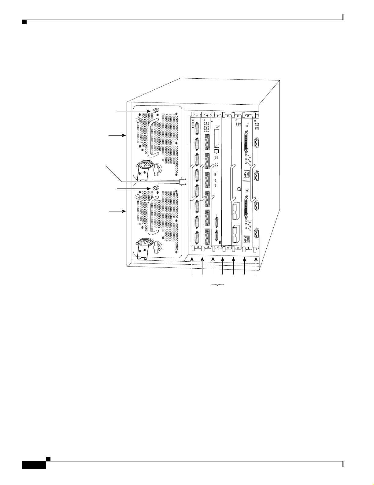
The Cisco 7505 ha s five slots: four in terface pro cessor slots (0 thr ough 3) a nd one slot for the R oute
Switch Processor (RSP2, RSP4/4+, or RSP8). The Cisco 7505 support s 4 VIPs, one for eac h interface
processor slot. T he C is co 7505 uses a sin gle power supp ly, with two models available: DC inp ut o r
AC inpu t.
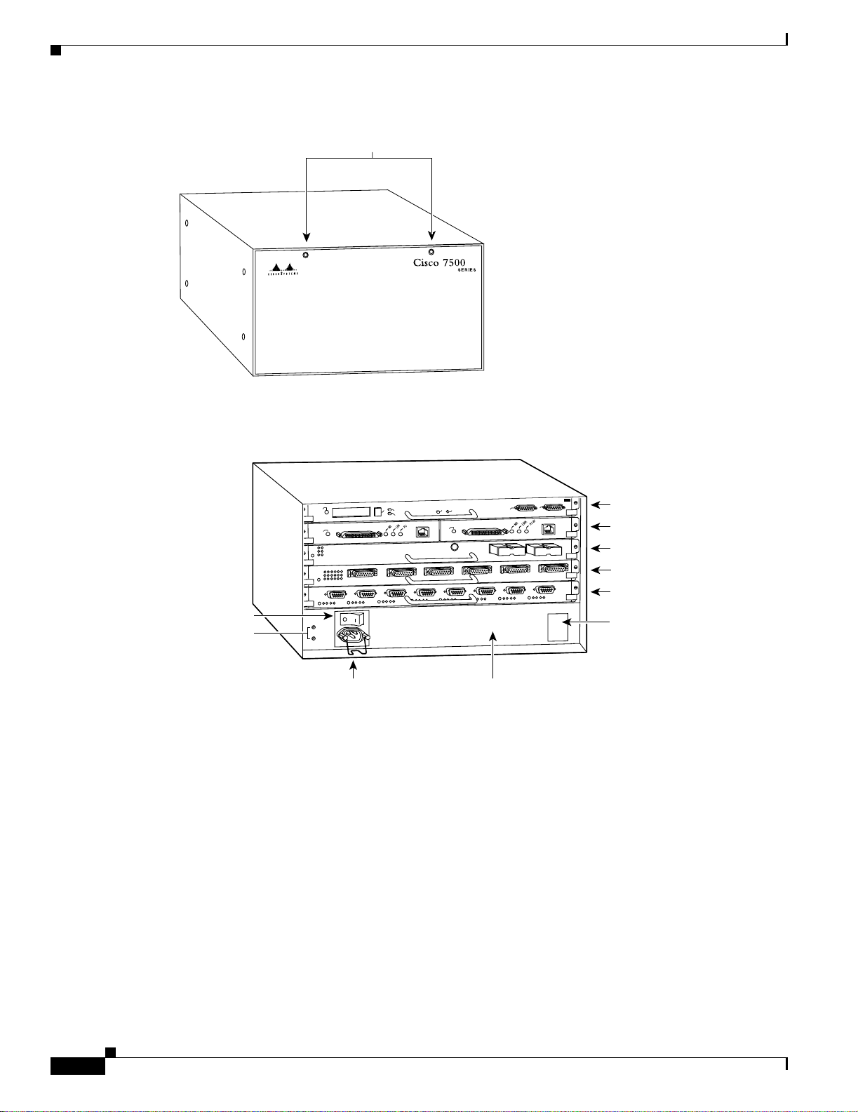
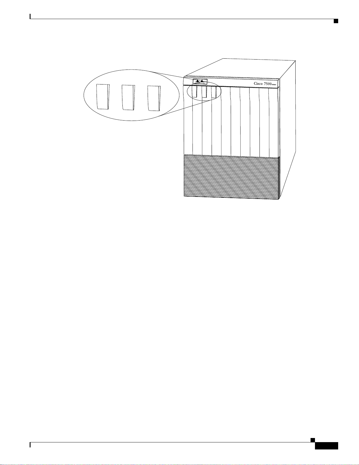
The front, or n oni nte rface proc es sor en d, of t he Cisco 7505 has a r emovable pane l t hat is se cu red w it h
two captive fasteners. See Figure 1-1. Removing the panel provides access to the internal components:
the power supply an d fan t r ay.
OL-5008-03 B0
Cisco 7500 Series Installation and Configuration Guide
1-3
Page 26
Cisco 7505 Overview
Chapter 1 Cisco 7500 Series Product Overview
Captive fasteners
H2009
Figure 1-2 shows details of the r ear, interface-processor end o f the Cisco 7505.
Figure 1-2 Cisco 7505 (Rear View)
R
O
S
S
E
C
O
R
P
H
C
T
I
W
S
E
T
U
O
Figure 1-1 Cisco 7505 (Front View)
R
E
.
L
X
O
U
S
A
N
O
C
RSP slot
Interface processor slot 3
Interface processor slot 2
Interface processor slot 1
Interface processor slot 0
DC OK LED
H2761
Power switch
Chassis
grounding
receptacles
T
L
A
T
C
1
E
T
J
E
L
A
M
R
O
N
E
L
B
A
N
E
O
L
0
S
T
O
L
S
T
H
E
S
U
E
P
R
C
E
L
B
A
N
E
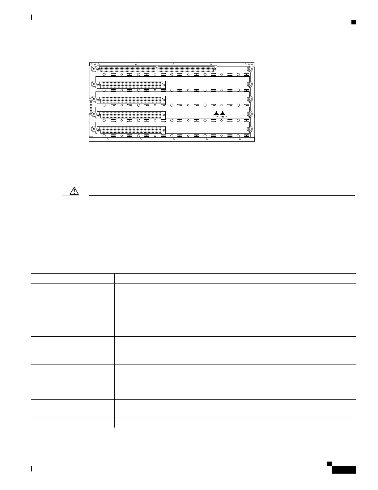
Cisco 7505 CyBus Backplane
The CyBus backplane in the Cisco 7505 provides the physical connections for the RSPs and interface
processors, and t ransfe rs i nf ormat ion a t up to 1. 067 Gbps.
The Cisco 7505 Cy Bus ba ck plan e has five slots: interfa ce p roc essor slot s 0 t hrou gh 3, and one slo t fo r
the RSP (RSP2, RSP4/4+, or RSP8), as shown in Figure 1-3.
Cisco 7500 Series Installation and Configuration Guide
1-4
Power receptacle AC-input power supply
OL-5008-03 B0
Page 27
Chapter 1 Cisco 7500 Series Product Overview
Figure 1-3 Cy Bus Backplane in the Cisco 7505
The backplane slots are keyed so that the processor modules can be installed only in the slots designated
for them. Keys on the backplane fit into two key guides on each module. Although the RSP uses unique
keys, all fo ur int erface processor slots use the same key, so you can install an interface processor in any
interface processor slot, but not in the RSP slot.
Cisco 7505 Overview
SLOT 4
SLOT 3
SLOT 2
SLOT 1
SLOT 0
H2875
Caution When installi ng an RSP, ensure that you are in stalling it in th e appropriat e slot to a v oid damaging the
key guides or the backplane.
Cisco 7505 System Specifications
Table 1-1 lists the specifications for the Cisco 7505 system.
Table 1-1 Cisco 7505 Specifications
Description Specification
High-speed backplan e 1.067 Gbps CyBus, 4 interface processo r slots, and 1 RSP slot
Dimensions (H x W x D) 10.5 x 17.5 x 17.0 in. (26.67 x 44.45 x 43. 18 cm )
Chassis depth including power cord and cable management brackets is
19 in. (48.26 cm )
We ight Chassis only (including power sup ply an d fa n arr ay): 46 lb (20.87 kg )
Chassis fully configured w ith 1 RSP and 4 inte rface proc ess ors: 70 lb (31.75 kg )
Power dissipation 600W maximum configuration with AC-input power supply
600W maximum c on figurati on wi th DC-i np ut p ower supply
Heat dissipation 715W (2440 Btu/hr)
Power distribution 75A maximum @ +5 VDC, 15A maximu m @ +12 VDC,
3A maximum @ –12 VDC, 5A maximum @ +24 VDC
AC-input rating 100 to 240 VAC, wide input with power factor corrector (PFC) ;
9A maximum @ 10 0 VAC, 4A max imum @ 2 40 VAC (at 600 W)
AC-input cable 12 AWG, with 3 leads, an IEC-320 plug on the router end, and a country-dependent plug on
the power source en d
Frequency 50 to 60 Hz
OL-5008-03 B0
Cisco 7500 Series Installation and Configuration Guide
1-5
Page 28
Chapter 1 Cisco 7500 Series Product Overview
Cisco 7507 Overview
Table 1-1 Cisco 7505 Specifications (continued)
Description Specification
DC-input rating –40 VDC minimum in North America (–56 VDC in European Union)
–48 VDC nominal in North America (–60 VDC in European Union)
–52 VDC maximum in North America (–72 VDC in European Union)
20A maximum at –48 V DC and 16A maxi mum @ –60 VDC
DC-input cable 10 AWG, recommended mi nimum w ire gauge (you provide the w ire)
DC-input hold-up time 10 ms of output after the DC input has bee n interrup ted
Airflow Side-to-side thro ugh the cha ssis using a variable- speed , 6-fan array
Temperature 32 to 104°F (0 to 40°C), operat ing; –4 to 149°F (–20 to 65°C), n ono pera ting
Humidity 10 to 90%, noncond en sing
Software requ ire me nt RSP2 – Cis co IO S Relea se 10. 3(6) or a l ater re le ase o f 10.3
RSP4/4+ – Cisco IOS Rele ase 11.1(8)CA or a late r relea se o f 1 1. 1
RSP8 – Cisco IOS Rele ase 12. 0(9)S or a l ater re lease o f 12.0 S
Agency approvals Safety: UL 1950, CSA 22.2-No. 950, EN60950, EN41003, AUSTEL TS001, AS/NZS 3260,
IEC 801-2, 3, 4, 5, and 6 EMI: FCC Class A, VCC I Class II, an d CISPR 22 B (EN 55022)
Conducted Emissions
Cisco 7507 Overview
The Cisco 7507 supports multiprotocol, multimedia routing and bridging with a wide variety of
protocols and any combination of available electrica l interfaces and me dia.
Network interfaces re side on int erfac e pr oc ess ors tha t pr ovide a d ire ct con necti on bet wee n the two
CyBuses in the Cisco 7507 and your external net works. The Cisco 7507 has seven slots: interface
processor slots 0 and 1, Route Switc h Processor (RSP2 , RSP4/4+, RSP8, or RSP16) slots 2 and 3, and
interface processor slots 4 through 6. The Cisco 7507 sup ports 5 VIPs, one for each i nterface processor
slot.
There are bays for up to two AC-input or DC-input power supp lies. Th e chas sis will opera te with one
power supply. Although a second power supply is not re quire d, it al lows load sha rin g a nd inc rea sed
system availability.
Caution Because of agency compliance and saf ety issues, mi xing AC-input and DC- input power supp lies in
the same Cisco 75 07 is no t a sup por ted c onfigura tion a nd shoul d not be a ttemp ted . Do ing so m ight
cause damage.
The Cisco 7507 front panel, shown in Figure 1-4, contains three status indicators and two removable
panels for access to the internal components. The three light emitting diodes (LEDs) on the front panel
indicate normal syste m operat ion and th e current ly active power supplies. On t he back of th e router, a
normal LED on the RSP an d LE Ds on the p ower supplies indi ca te the same sta tus.
1-6
Cisco 7500 Series Installation and Configuration Guide
OL-5008-03 B0
Page 29
Chapter 1 Cisco 7500 Series Product Overview
Figure 1-4 Cisco 7507 (Front View)
U
P
PER
PO
W
E
R
Cisco 7507 Overview
U
P
P
E
R
L
O
W
L
O
W
ER
P
O
W
ER
N
O
R
M
AL
E
R
N
O
R
M
A
L
P
O
W
E
R
P
O
W
E
R
H3135
OL-5008-03 B0
Cisco 7500 Series Installation and Configuration Guide
1-7
Page 30
Cisco 7507 Overview
Chapter 1 Cisco 7500 Series Product Overview
Figure 1-5 shows details on the r ear, interface-processor end o f the Cisco 7 507.
Figure 1-5 Cisco 7507 (Rear View)
Captive
installation screw
Upper
power supply
D
C
F
A
IL
A
C
P
O
W
E
R
NORMAL
E
N
A
B
LE
Chassis
grounding
receptacles
O
Captive
installation screw
D
C
F
A
IL
A
C
P
O
W
E
R
Lower
power supply
O
Cisco 7507 Dual CyBus Backplane
EJECT
SLOT 1
I
I
Slot 0
SLOT 0
MASTER
SLAVE
SLAVE/MASTER
CPU HALT
RESET
AUX.
ROUTE SWITCH PROCESSOR 2
CONSOLE
2
1
34 5 6
E
N
A
B
L
E
H3888
RSP slots
1-8
The dual CyBus backplane provides the physical connections for the RSPs and interface processors, and
transfers informati on a t up to 2. 134 Gbps (1.067 Gb ps pe r C yBu s). T he du al CyBu s h as seven slots:
interface processor slots 0 and 1 (CyBus 0), RSP slots 2 and 3, and interface processor slots 4 through 6
(CyBus 1), as shown in Figure 1-6.
Cisco 7500 Series Installation and Configuration Guide
OL-5008-03 B0
Page 31

Chapter 1 Cisco 7500 Series Product Overview
Figure 1-6 Dual CyBus Backplane in the Cisco 7507
Cisco 7507 Overview
Interface
processor
slots 0 and 1
SLOT 0
SLOT 1
RSP
slots 2
and 3
SLOT 2
SLOT 3
Interface
processor
slots 4–6
SLOT 4
SLOT 5
SLOT 6
H3886
CyBus 0
CyBus 1
An RSP2, RSP4/4+, RSP8, or RSP 16 in either slot 2 or slot 3 controls both CyBus 0 and CyBus 1. The
dual CyBus backplane in the Cisco 7507 ha s an aggregate bandwid th of 2. 134 Gb ps. The two CyBuses
are independent of one another. Interface processors connected to one CyBus are unaffected by the traffic
generated by the i nte rface pr oces sors c onnec ted t o th e othe r.
The backplane slots are keyed so that the processor modules can be installed only in the slots designated
for them. Keys on the backplane fit into two key guides on each module. Although the RSP uses unique
keys, all five interface processor slots use the same key, so you can install an interface processor in any
interface processor slot, but not in the RSP slot.
OL-5008-03 B0
Cisco 7500 Series Installation and Configuration Guide
1-9
Page 32

Chapter 1 Cisco 7500 Series Product Overview
Cisco 7507 Overview
Cisco 7507 System Specifications
Table 1-2 lists the specifications for the Cisco 7507 system.
Table 1-2 Cisco 7507 Specifications
Description Specification
High-speed backp lan e Two 1.0677-Gbps CyB uses, 5 in terfa ce p roce ssor sl ots, 2 RSP slo ts
Dimensions (H x W x D) 19.25 x 17.5 x 25.1 in. (48.90 x 44.45 x 63.75 cm)
Chassis depth includin g p ower cord i s 28 in. (71. 12 cm )
We ight Chassis only: 76 lb ( 34.47 kg)
Chassis fully configured, using all slots and 2 power supplies:
145 lb (65.76 kg)
Power supply 700W maximum (fo r AC-input an d DC- input power supp lies)
Power dissipation 626W maximum configurati on
530W typical with maximum configuration
Heat dissipation 1200W (4100 Btu/hr) with AC-input
300W (1024 Btu/hr) w it h DC -inpu t
AC-input voltage 100 to 240 VAC, wide input with power factor correcto r (PFC)
AC-input cable 12 AWG , w it h 3 le ad s, an I EC- 320 plu g o n the rou ter e nd, a nd a c ou ntry- de pende nt plug on
the power source end
Frequency 50 to 60 Hz autoranging
AC-input ratings 10A maximum @ 100 VAC, 6A maximum @ 240 VAC, chassis fully configured
DC-input ratings –40 VDC minimum, –48 VDC nominal, –72 VDC maximum
Power distribution +5.2 VDC @ 95A, +12 VDC @ 15A, –12 VDC @ 5A, +24 VDC @ 4A
DC-input cable 8 AWG, recommen ded minimu m wire gau ge (you provide thewire)
Airflow 140 cfm through t he syst em blower
Operating temperature 32 to 104°F (0 to 40°C)
Nonoperating tempera ture –4 to 149°F (–20 to 65°C)
Humidity 10 to 90%, noncond en sing
Software requ ire me nt RSP2 – Cisco IO S Relea se 10 .3(6 ) or a la ter re le ase o f 10. 3
RSP4/4+ – Cisco IOS Rele as e 11.1(8)CA or a l ater re lease o f 11. 1
RSP8 – Cisco IOS Re leas e 12 .0( 9)S or a la ter rel ease o f 12. 0 S
RSP16 – Cisco IOS Release 12.1(12)E and later and Cisco IOS 12.0(21.02 )S and later
Agency approvals Safety: UL 1950, CSA 22.2-9 50, EN6095 0: 1992 EM I: FCC Class A, EN 55022 Cla ss B,
VCCI Class 2
1-10
Cisco 7500 Series Installation and Configuration Guide
OL-5008-03 B0
Page 33

Chapter 1 Cisco 7500 Series Product Overview
Cisco 7507-MX Overview
The Cisco 7507-M X suppor t s m ultip rotoc ol, m ultim edi a ro uting an d b ridg in g wit h a wid e variety o f
protocols and any combination of available electrica l interfaces and me dia.
Network interfaces reside on interface processors that provide a direct connection between the two
CyBuses in the Cisco 750 7-MX and yo ur external ne tworks. T he C isco 7507-MX has seven slots:
interface processor slots 0 and 1, Route Swit ch Processor (RSP2 , RSP4/4+, RSP8, or RSP16)
slots 2 and 3, and interface pr ocesso r slots 4 t hrough 6 . The Cisco 75 07-MX supports 5 VIPs, o ne f or
each interface processor slot.
There are bays for up to two AC-input or DC-input power supp lies. Th e chas sis will opera te with one
power supply. Although a second power supply is not re quire d, it al lows load sha rin g a nd inc rea sed
system availability.
Caution Because of agency compliance and saf ety issues, mi xing AC-input and DC- input power supp lies in
the same Cisco 75 07- MX is not a sup por ted configura tion and sho uld not be a ttemp t ed. Do in g so
might cause da mage .
Cisco 7507-MX Overview
The Cisco 7507-MX front panel, shown in Figure 1-7, contains three status indicators and two removable
panels for access to the internal components. The three light emitting diodes (LEDs) on the front panel
indicate normal syste m operat ion and th e curre ntly act ive power supplies. On the back of th e rout er, a
normal LED on the RSP an d LE Ds on the p ower supplies indi ca te the same sta tus.
Figure 1-7 Cisco 7507-MX (Front View)
U
P
PER
PO
W
ER
LO
W
ER
PO
W
ER
N
O
RM
A
L
U
P
P
E
R
L
O
W
E
R
N
O
R
M
A
L
P
O
W
E
R
P
O
W
E
R
122302
OL-5008-03 B0
Cisco 7500 Series Installation and Configuration Guide
1-11
Page 34

Cisco 7507-MX Overview
Chapter 1 Cisco 7500 Series Product Overview
Figure 1-8 shows details on the r ear, interface-processor end o f th e Cisco 7 507 -MX.
Figure 1-8 Cisco 7507-MX (Rear View)
Captive
installation screw
Upper
power supply
D
C
F
A
IL
A
C
P
O
W
E
R
NORMAL
E
N
A
B
L
E
Chassis
grounding
receptacles
I
O
Captive
installation screw
D
C
F
A
IL
A
C
P
O
W
E
R
Lower
power supply
I
O
Cisco 7507-MX Dual CyBus Backplane
Slot 0
1
RSP slots
EJECT
SLOT 1
SLOT 0
MASTER
SLAVE
SLAVE/MASTER
CPU HALT
RESET
AUX.
ROUTE SWITCH PROCESSOR 2
CONSOLE
2
34 5 6
E
N
A
B
LE
H3888
1-12
The dual CyBus backplane provides the physical connections for the RSPs and interface processors, and
transfers informati on a t up to 2. 134 Gbps (1.067 Gb ps pe r C yBu s). T he du al CyBu s h as seven slots:
interface processor slots 0 and 1 (CyBus 0), RSP slots 2 and 3, and interface processor slots 4 through 6
(CyBus 1), as shown in Figure 1-9.
Cisco 7500 Series Installation and Configuration Guide
OL-5008-03 B0
Page 35

Chapter 1 Cisco 7500 Series Product Overview
Figure 1-9 Dual CyBus Backplane in the Cisco 7507-MX
Cisco 7507-MX Overview
Interface
processor
slots 0 and 1
SLOT 0
SLOT 1
RSP
slots 2
and 3
SLOT 2
SLOT 3
Interface
processor
slots 4–6
SLOT 4
SLOT 5
SLOT 6
28928
CyBus 0
CyBus 1
Note The Cisco 7507-MX backplane includes connectors for time-division multiplexing
(TDM)-compatib le h ardwa re. Th ese con ne ctor s a ll ow you to c onn ect th e Cisco 7507-MX to f ut ure
TDM hardware as it beco mes av aila ble. The Cis co 7507- MX also includ es Cisco’s turbo arbiter. The
turbo arbiter, when used in conjunction with other future hardware, significantly increases system
bandwidth. When not used with this future hardware, the turbo arbiter operates in standard CyBus
mode.
An RSP2, RSP4/4+, or R SP8 in eithe r sl ot 2 o r slo t 3 co ntro ls bo th Cy Bus 0 and C yBu s 1. The d ual
CyBus backplane in the Ci sco 7507-M X ha s an a ggr egate bandw idth of 2.1 34 Gbp s. T he two CyBuse s
are independent of one another. Interface processors connected to one CyBus are unaffected by the traffic
generated by the i nte rface pr oces sors c onnec ted t o th e othe r.
The backplane slots are keyed so that the processor modules can be installed only in the slots designated
for them. Keys on the backplane fit into two key guides on each module. Although the RSP uses unique
keys, all five interface processor slots use the same key, so you can install an interface processor in any
interface processor slot, but not in the RSP slot.
OL-5008-03 B0
Cisco 7500 Series Installation and Configuration Guide
1-13
Page 36

Chapter 1 Cisco 7500 Series Product Overview
Cisco 7507-MX Overview
Cisco 7507-MX System Specifications
Table 1-3 lists the specifications for the Cisco 7507-MX system.
Table 1-3 Cisco 7507-MX Specifications
Description Specification
High-speed backplan e Two 1.0677-Gbps CyBu ses, 5 interfac e processor sl ots, 2 RSP slots
Dimensions (H x W x D) 19.25 x 17.5 x 25.1 in. (48.90 x 44.45 x 63.75 cm)
Chassis depth inc luding p ower cord is 28 in. (7 1.1 2 cm )
We ight Chassis only: 76 lb (3 4.4 7 kg)
Chassis fully configured, using all slots and 2 power supplies:
145 lb (65.76 kg)
Power supply 700W m ax imum (for AC-input and DC- input power suppli es)
Power dissipation 626W maximum configura tion
530W typical with maximum configuration
Heat dissipation 1200W (4100 Bt u/hr) with AC-input
300W (1024 Btu /hr) wi th D C-i npu t
AC-input voltage 100 to 240 VAC, wide inp ut w it h power factor cor rect or ( PFC)
AC-input cable 12 AWG, with 3 leads, an IEC-320 plu g o n the r oute r end , a nd a country-depe ndent plu g
on the power source en d
Frequency 50 to 60 Hz a utor angi ng
AC-input ratings 10A maximum @ 100 VAC, 6A ma ximu m @ 240 VAC, chassi s ful ly con figured
DC-input ratings –40 VDC minimum, –48 VDC nomi nal, –72 VDC maximum
Power distribution +5.2 VDC @ 95A, +12 VDC @ 1 5A, –12 VDC @ 5A, +24 VDC @ 4A
DC-input cable 8 AWG, reco mmen ded minimu m wire gaug e (you provide the wire)
Airflow 140 cfm through t he s yst em blower
Operating temperature 32 to 104°F (0 to 40°C)
Nonoperating tempera ture –4 to 149°F (–20 to 65°C)
Humidity 10 to 90%, noncondensin g
Software requ ire me nt RSP2 – Cisco IO S Releas e 10.3(6 ) or a later relea se of 10.3
RSP4/4+ – Cisco IOS Rel ease 1 1.1(8 )CA o r a lat er re leas e of 1 1.1
RSP8 – Cisco IO S Rel eas e 12.0(9 )S or a l ater re lease o f 12. 0 S
RSP16 – Cisco IOS Release 12.1(12)E and later and Cisco IOS 12.0(21.02)S and later
Agency approvals Safety: UL 1950, C SA 22.2- 950, EN 60950: 1 992 E MI : FCC Clas s A , EN 55022 Cl ass B,
VCCI Class 2
1-14
Cisco 7500 Series Installation and Configuration Guide
OL-5008-03 B0
Page 37

Chapter 1 Cisco 7500 Series Product Overview
Cisco 7513 Overview
The Cisco 7513 router suppo rts multiprotoc ol, multimedia routing and br idging with a wide variety of
protocols and any combination of available electrical interfaces and media. Network interfaces reside on
interface processors that provi de a direct connecti on betwee n the two CyBus es in the Cisco 7513 and
your external networks. The Cisco 7513 has 13 slots: interface processor slots 0 through 5, Route Switch
Processor (RSP2, RSP4/4+, RSP8, or RSP16 ) slots 6 a nd 7, an d int erface proc essor sl ots 8 thr oug h 12.
The Cisco 7513 sup por ts 11 VIPs, one for e ach int erfac e pr oc ess or sl ot.
There are bays for up to two AC-input or DC-input power supp lies. Th e chas sis will opera te with one
power supply. Although a second power supply is not re quire d, it al lows load sha rin g a nd inc rea sed
system availability.
Caution Because of agency compliance and safety i ssues, mixi ng AC-input and DC-in put power suppl ies in t he
same Cisco 7513 i s not a sup por ted co nfigurati on a nd shoul d n ot b e at te mpted. D oin g so mig ht c ause
damage.
The Cisco 7513 is shown in Figure 1-10. The three front-panel LEDs indicate system and power supply
status, and LEDs on the RSP, interface processors, and power supplies indicate status.
Cisco 7513 Overview
OL-5008-03 B0
Cisco 7500 Series Installation and Configuration Guide
1-15
Page 38

Cisco 7513 Overview
Chapter 1 Cisco 7500 Series Product Overview
Figure 1-10 Cisco 7513 (Front View)
Front-panel
LEDs
POWER
POWER
A
NORMAL
B
122303
1-16
Cisco 7500 Series Installation and Configuration Guide
OL-5008-03 B0
Page 39

Chapter 1 Cisco 7500 Series Product Overview
Figure 1-11 shows details on the rear, interface-p rocessor en d of the Cisc o 751 3.
Figure 1-11 Cisco 7513 (Rear View)
Blower module
Cable-management
bracket
Card cage and
processor modules
Cisco 7513 Overview
NO
R
MAL
E
JEC
T
SLO
SLO
T 1
T 0
M
SLA
A
S
TE
VE
R
SLAVE
/M
AS
TER
CPU
H
ALT
RE
SET
E
NABLE
ENAB
LE
Air intake vent
P
O
W
E
Power supplies
Chassis grounding
receptacles
R
A
0
Cisco 7513 Dual CyBus Backplane
The dual CyBus backplane, located at the rear of the Cisco 7513 removable card cage, provides the
physical connectio ns for t he R SPs a nd i nter face pr ocesso rs, and t ransfe rs i nform ati on at up t o
2.134 Gbps (1.067 Gb ps per CyBu s).
The dual CyBus ha s 13 sl ots: int erfac e pr ocesso r slots 0 t hroug h 5 (CyBu s 0); two RSP slots (slots
6 and 7); in terface p roce ssor sl ots 8 th rou gh 12 (Cy Bus 1), as shown in Figure 1-12.
AU
X.
R
O
U
T
E
C
ON
S
W
SO
LE
I
T
C
H
P
R
O
C
E
S
S
O
R
2
A
C
F
A
N
O
U
T
P
U
T
O
K
O
K
F
A
IL
I
A
C
F
A
N
O
U
T
P
U
T
O
K
O
K
F
A
IL
P
O
W
E
R
B
I
122373
0
OL-5008-03 B0
Cisco 7500 Series Installation and Configuration Guide
1-17
Page 40

Cisco 7513 Overview
Chapter 1 Cisco 7500 Series Product Overview
Figure 1-12 Dual CyBus Backplane in the Cisco7513
012345RSPRSP89101112
CyBus 0 (slots 0 through 5) CyBus 1 (slots 8 through 12)
H3163
An RSP2, RSP4/4+, or R SP8 in eithe r sl ot 6 o r slo t 7 co ntro ls bo th Cy Bus 0 and C yBu s 1. The d ual
CyBus backplane in the C isco 7513 has an ag gregate b andw idth o f 2.1 34 G bps. Int erface proc esso rs
connected to one CyB u s are unaffected by the traffic generated by the interface processors connected to
the other CyBus. The two CyBuses are independent of one another.
The backplane slots are keyed so that the processor modules can be installed only in the slots designated
for them. Keys on the backplane fit into two key guides on each module. Although the RSP uses unique
keys, all eleven interface processor slots use the same key, so you can install an interface processor in
any interface processor slot, but not in the RSP slot.
Note A spare card cage assembly ships as Pro duct Num ber MAS- 7513CDCAGE=. For maintenanc e
information about the card cage assembly, see the “Removing and Replacing the Cisco 7513, Cisco
7513-MX, and Cisco 7576 Card Cage Assembl y” sect ion on p age 7-5.
1-18
Cisco 7500 Series Installation and Configuration Guide
OL-5008-03 B0
Page 41
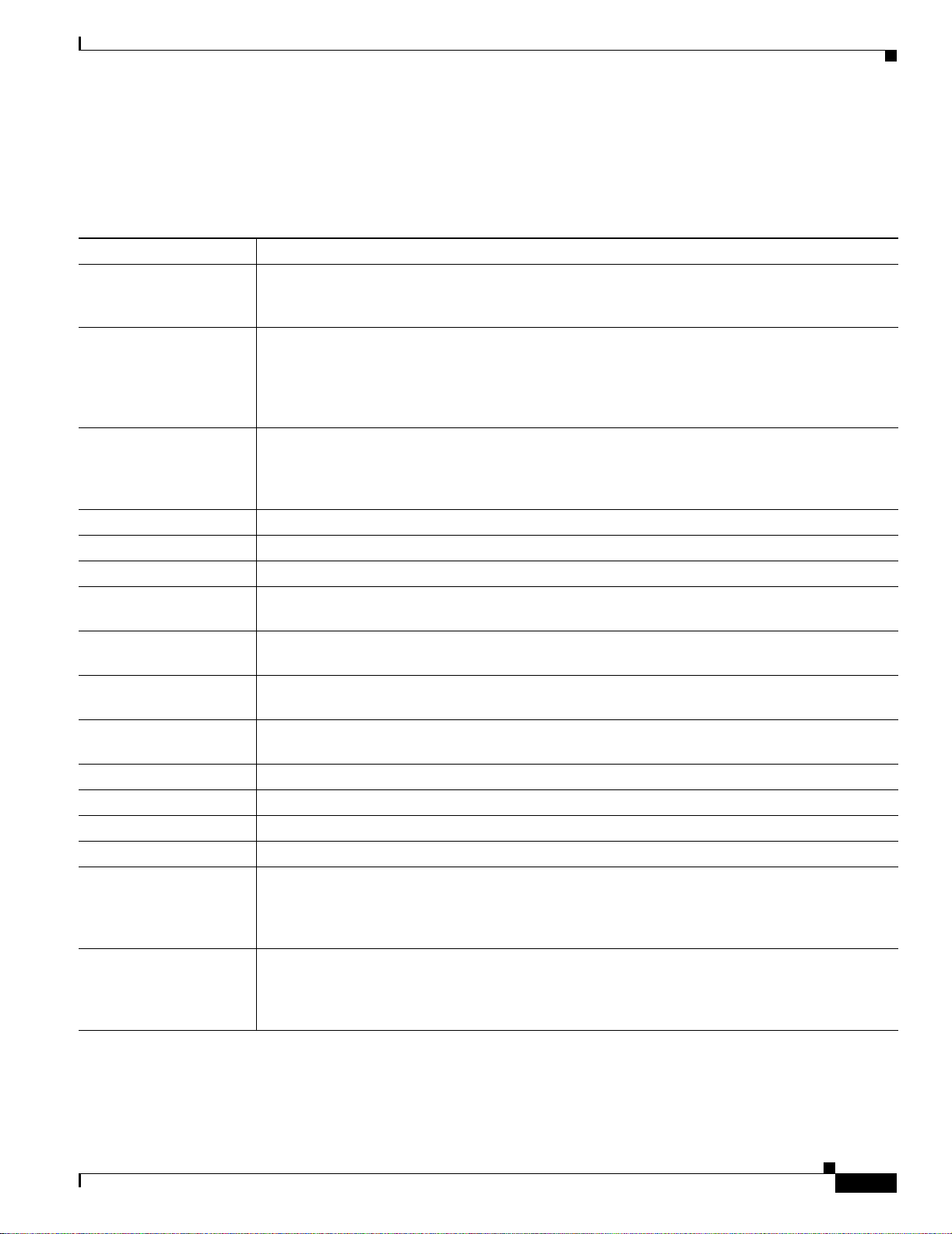
Chapter 1 Cisco 7500 Series Product Overview
Cisco 7513 Overview
Cisco 7513 System Specifications
Table 1-4 lists the specifications for the Cisco 7513 system.
Table 1-4 Cisco 7513 Specifications
Backplane Two 1.0677- Gbps CyBuses , 11 interface processor slots, 2 RSP slots
Dimensions
(H x W x D)
We ight Chassis with blower module: 75 lb (34. 02 kg)
Power dissipation 160 0W with a maximum configuration and 1 AC-input power supply
Heat dissipation 1600W (5461 Btu/hr)
AC-input voltage 100 to 240 VAC
Frequency 50/60 Hz
AC-input cable
1
AC-input voltage
and current
DC-input voltage
and current
DC-input cable 8 AWG (recommended minimum), with 3 leads and rated for at least 194°F (90°C) (you sup ply
Power distribution +5.2 VDC @ 75A, +12 VDC @ 15A, –12 VDC @ 3A, +24 VDC @ 5A
Airflow/noise level Bottom to top th rou gh c has sis by variable- spe ed b lower (6 2 to 70 d BA)
Temperature 32 to 104°F (0 to 40°C), operating; –4 to 149°F (–20 to 65°C), nonopera ting
Relative humidity 10 to 90%, noncondensing
Software requ ire me nt RSP2 – Cisco IOS Release 10.3(6) or a later re lease of 10.3
Agency approvals Safety: UL 1950, CSA 22.2-95 0, EN6095 0, EN4 1003, TS0 01, AS/NZS 3260
1. The Cisco 7513 requires a min imum of 20A service with a 20A receptacle at the power source. The p owe r cab le s up plied w ith the Cisco 7513 uses a 20A
male plug.
33.75 x 17.5 x 2 2 in . (85.73 x 44 .45 x 55.88 cm)
Chassis width includi ng rac k-mou nt flang es is 1 8.9 3 in . (48 .1 cm )
Chassis depth includin g p ower cables a nd ca ble -man agem ent brac ket: 24 in. ( 60.96 cm)
Chassis with blower module an d 1 power sup ply: 1 00 l b (45.36 kg )
Chassis with blower module an d 2 power sup plies: 125 lb (56 .7 kg)
Chassis with blower module, 2 power supplies, and all slots filled: ~160 l b (72.58 kg),
each processor mo dul e w ei ghs ~ 2.5 lb (1. 13 kg )
1600W with a maxim um configura tion a nd 1 DC-inp ut power suppl y
1700W nominal with a m axim um c onfigura tio n and e ith er 2 AC-input o r 2 DC- i nput power
supplies
12 AWG , w it h 3 le ad s, an IE C- 320 plu g o n th e rou ter e nd, a nd a c oun try- de pende nt plug on the
power source end
100 VAC at 16 amps (A) maximum, wide input with power facto r correcto r (PFC)
240 VAC at 7A maximum
–48 VDC nominal at 35A in North America
(–60 VDC at 35A in the Eur opean Un ion)
the cable)
RSP4/4+ – Cisco IOS Release 11.1(8)CA or a later release of 11.1
RSP8 – Cisco IOS Release 12.0( 9)S or a later rel ease of 12.0 S
RSP16 – Cisco IOS Release 12.1(12)E and later and Cisco IOS 12.0(21.02)S and later
EMI: FCC Class A, EN60555-2, EN5502 2 Class B, VDE 087 8 Part 3, 30 Cl ass B Immunit y:
EN55101/2 (ESD), E N551 01/3 (RFI ), E N 55101/ 4 (Bu rst), E N551 01/5 (Su rge), EN 55101 /6
(Conducted), IEC77B (AC Disturbanc e)
OL-5008-03 B0
Cisco 7500 Series Installation and Configuration Guide
1-19
Page 42

Cisco 7513-MX Overview
Cisco 7513-MX Overview
The Cisco 7513-MX router supports multiprotocol, multimedia routing and bridging with a wide variety
of protocols and any combination of available electrical interfaces and media. Network interfaces reside
on interface processors that provide a direct connection between the two CyBuses in the Cisco 7513-MX
and your external n etworks. The Cisc o 7513-MX has 13 sl ots: i nte rface proc essor slot s 0 thr ough 5,
Route Switch Processor (RSP2, RSP4/4+, RSP8, or RSP16) slots 6 and 7, and interface processor slots
8 through 12. The Cisco 7513-MX supports 11 VIPs, one for each interface proce ssor slot.
There are bays for up to two AC-input or DC-input power supp lies. Th e chas sis will opera te with one
power supply. Although a second power supply is not re quire d, it al lows load sha rin g a nd inc rea sed
system availability.
Caution Because of agency compliance and safety i ssues , mi xing AC-input and DC-in put power suppli es in the
same Cisco 7513-MX is not a supporte d configurati on and shoul d not be attempt ed. Doing so might
cause damage.
The Cisco 7513 -MX is sh own in Figu re 1- 13 . The thre e front-p anel LEDs indica te syst em and power
supply status, and LEDs on the RSP, interface processors, and power supplies indicate stat us.
Chapter 1 Cisco 7500 Series Product Overview
1-20
Cisco 7500 Series Installation and Configuration Guide
OL-5008-03 B0
Page 43

Chapter 1 Cisco 7500 Series Product Overview
Figure 1-13 Cisco 7513-MX (Front View)
Cisco 7513-MX Overview
Front-panel
LEDs
POWER
POWER
A
NORMAL
B
122303
OL-5008-03 B0
Cisco 7500 Series Installation and Configuration Guide
1-21
Page 44

Cisco 7513-MX Overview
Chapter 1 Cisco 7500 Series Product Overview
Figure 1-14 shows details on the rear, interface-p rocessor en d of the Cisco 751 3-MX .
Figure 1-14 Cisco 7513-MX (Rear View)
Blower module
Cable-management
bracket
Card cage and
processor modules
NO
R
MA
L
E
JEC
T
SLOT 1
SLO
T 0
M
S
A
LAV
STER
E
SLAVE
/M
AS
TER
CPU
H
ALT
RE
SET
EN
ABLE
ENAB
LE
Air intake vent
A
C
F
A
N
O
U
T
P
U
T
O
K
O
K
F
A
IL
P
O
W
E
Power supplies
Chassis grounding
receptacles
R
A
I
0
Cisco 7513-MX Dual CyBus Backplane
The dual CyBus backp lane, locat ed at the r ear o f the Cisco 7513-MX remov able ca rd ca ge, p ro vides th e
physical connectio ns for t he R SPs a nd i nter face pr ocesso rs, and t ransfe rs i nform ati on at up t o
2.134 Gbps (1.067 Gb ps per CyBu s).
The dual CyBus ha s 13 sl ots: int erfac e pr ocesso r slots 0 t hroug h 5 (CyBu s 0); two RSP slots (slots
6 and 7); in terface p roce ssor sl ots 8 th rou gh 12 (Cy Bus 1), as shown in Figure 1-15.
AUX
.
R
O
U
T
E
C
ON
S
W
SO
LE
I
T
C
H
P
R
O
C
E
S
S
O
R
2
A
C
F
A
N
O
U
T
P
U
T
O
K
O
K
F
A
IL
P
O
W
E
R
B
I
122374
0
1-22
Cisco 7500 Series Installation and Configuration Guide
OL-5008-03 B0
Page 45

Chapter 1 Cisco 7500 Series Product Overview
Figure 1-15 Dual CyBus Backplane in the Cisco 7513-MX
Cisco 7513-MX Overview
012345RSPRSP89101112
CyBus 0 (slots 0 through 5) CyBus 1 (slots 8 through 12)
Note The Cisco 7513-MX backplane includes connectors for time-division multiplexing (TDM)-compatible
28929
hardware. These connec tors all ow you to connect the Cisco 7513-MX to future TDM ha rdware as it
becomes available. The C isco 751 3-M X a lso in clu des the Ci sco tur bo arbi ter. The turbo ar biter, when
used in conjunction with other future hardware, significantly increases system bandwidth. When not
used with this future hardware, the turbo arbiter operates in standard CyBus mode.
An RSP2, RSP4/4+, or R SP8 in eithe r sl ot 6 o r slo t 7 co ntro ls bo th Cy Bus 0 and C yBu s 1. The d ual
CyBus backplane in the Cisco 7513-MX has an aggregate bandwidth of 2.134 Gbps. Interface processors
connected to one CyB u s are unaffected by the traffic generated by the in ter f ace processors connected to
the other CyBus. The two CyBuses are independent of one another.
The backplane slots are keyed so that the processor modules can be installed only in the slots designated
for them. Keys on the backplane fit into two key guides on each module. Although the RSP uses unique
keys, all eleven interface processor slots use the same key, so you can install an interface processor in
any interface processor slot, but not in the RSP slot.
Note A spare card cage assembly ships as Pro duct Num ber MAS- 7513MX- CDCAGE=. For maintenance
information about t he c ard ca ge a ssemb ly, see the “Removing and Replacing the Cisco 7513, Cisco
7513-MX, and Cisco 7576 Card Cage Assembl y” section on page 7-5.
OL-5008-03 B0
Cisco 7500 Series Installation and Configuration Guide
1-23
Page 46

Chapter 1 Cisco 7500 Series Product Overview
Cisco 7513-MX Overview
Cisco 7513-MX System Specifications
Table 1-5 lists the specifications for the Cisco 7513-MX system.
Table 1-5 Cisco 7513-MX Specifications
Description Specification
Backplane Two 1.0677-Gbps CyBuses: 11 interface proc essor slot s, 2 RSP sl ots
Dimensions
(H x W x D)
We ight Chassis with blower module: 75 lb (34.02 kg)
Power dissipation 1600W with a maximum configu ratio n and 1 AC-input power supply
Heat dissipation 1600W (5461 Btu/hr)
AC-input voltage 100 to 240 VAC
Frequency 50/60 Hz
1
AC-input cable
AC-input voltage
and current
DC-input voltage
and current
DC-input cable 8 AWG (recom mended minim um), with 3 leads an d rated for at leas t 194°F (90°C) (you supply the
Power distribution +5.2 VDC @ 75A, +12 VDC @ 15A, –12 VDC @ 3A, +24 VDC @ 5A
Airflow/noise level Bottom to top through chassis by variable-speed blower (62 to 70 dBA)
Temperature 32 to 104°F (0 to 40°C), op erati ng; –4 to 149°F (–20 to 65°C), nonope rating
Relative humidity 10 to 90%, noncondensing
Software requ ire me nt RSP2 – Cisco I OS Re leas e 10 .3( 6) or a l at er r elease of 10. 3
Agency approvals Safety: UL 1950, CSA 2 2. 2-9 50, E N609 50, E N4100 3, TS 001, A S/ NZS 3260
1. The Cisco 7513-MX requires a minimum of 20A service with a 20A receptacle at the power source. The power cable supplied with the Cisco 7513-MX
uses a 20A m ale pl ug.
33.75 x 17.5 x 22 in. (85.73 x 44.4 5 x 55.88 c m)
Chassis width includi ng rac k-mou nt f l anges i s 1 8.93 in . (48 .1 c m)
Chassis depth incl udin g power cabl es a nd cabl e-m an agem ent brac ket is 24 in. ( 60.96 cm)
Chassis with blower module and 1 power supply: 100 lb (45.36 kg)
Chassis with blower module and 2 power supplies: 125 lb (56.7 kg)
Chassis with blower module, 2 powe r supplies, and all slots filled: ~160 lb (72.58 kg),
each processor modu le wei ghs ~2. 5 lb (1 .13 k g)
1600W with a max imum configura tion a nd 1 D C-in put power suppl y
1700W nominal wi th a m aximum c on figurati on an d e it her 2 AC-input o r 2 D C -inpu t power
supplies
12 AWG, with 3 lead s, an IEC-320 plug on th e router end, and a country-depende nt plug on the
power source end
100 VAC at 16 amps (A) maximum, wide input with power factor co rrec tor (PFC)
240 VAC at 7A maximum
–48 VDC nominal at 35A in Nor th Amer ica ( –60 VDC at 35A in the European Union)
cable)
RSP4/4+ – Cisco IOS Rel ea se 11.1(8)CA or a l ater rel ease o f 11. 1
RSP8 – Cisco IOS Rel ease 12.0( 9) S or a l ater rele ase of 12. 0 S
RSP16 – Cisco IOS Release 12.1(12)E and later and Cisco IOS 12.0(21.02)S and later
EMI: FCC Class A, EN60555-2, EN550 22 Class B, VDE 08 78 Part 3, 30 Class B
Immunity: EN55101/2 (E SD), EN55 101/3 (RFI) , EN55101 /4 (Burs t), EN55 101/5 (Surge),
EN55101/6 (Conduc ted ), IE C7 7B (AC Disturb ance)
1-24
Cisco 7500 Series Installation and Configuration Guide
OL-5008-03 B0
Page 47

Chapter 1 Cisco 7500 Series Product Overview
Cisco 7576 Overview
The Cisco 7576 router s upports multipr otocol, multime dia r outing a nd bridging with a wide variety of
protocols and any comb inat ion of available e lec tric al i nte rfac es and me dia . T he Ci sco 7576 consists o f
two independent Cisco 7500 series routers configured on a single split backplane. This system is housed
within the chassis footprint of a Cisco 7513 router.
Network interfaces reside on interface processors that provide a direct connection between the two
independent dual CyBuses located on the backplane of the Cisco 7576 and your external networks. The
two independent dual CyB uses facilitate the configuration of two independent routers on a single
backplane. T hes e r out ers are i de nti fied as rou t er A a nd r oute r B.
The backplane of the Cisco 7576 has 13 slots. Router A uses in ter face proc essor sl ots 0 thro ugh 5 with
a Route Switch Processor (RSP4/4+ or RSP8) in slot 6. Router B uses interface processor slots 8 through
12 with a Route Switch Processor (RSP4/4+ or RSP8) in slot 7. The Ci sco 7576 supports 10 V IPs, one
for each interface processor slot; 6 VIPs are supported in Router A and 5 VIPs are supported in Router B.
There are bays for up to two AC-input or DC-input power supp lies. Th e chas sis will opera te with one
power supply. Although a second power supply is not re quire d, it al lows load sha rin g a nd inc rea sed
system availability.
Cisco 7576 Overview
Caution Because of agency compliance and safety i ssues, mixi ng AC-input and DC-in put power suppl ies in t he
same Cisco 7576 i s not a sup por ted co nfigurati on a nd shoul d n ot b e at te mpted. D oin g so mig ht c ause
damage.
Note The Cisco 7576 is s old as a new unit and as an upgrade kit to the Cisco 7513. When purchased new,
the Cisco 7576 comes standard with two AC-input power supplies and two RSP4/4+s. The
Cisco 7576 upgrade kit includes only the system chassis, which includes the card cage and
backplane. The u pgrad e kit d oes not inc lude p ower suppl ie s, RSPs, or int erfac e pr oc esso rs. T he se
parts are exchanged with the parts from the Cisco 7513 unit that is being upgraded. If you purchased
a Cisco 7576 upgrad e kit, re fer to the d ocument Cisco 7 513 an d Ci sco 7576 Chassis Replacem ent
and Upgrade Instructions.
Figure 1-16 shows the front view of the Cisco 7576. The three front-pa nel LEDs indicate syst em and
power supply status, and LED s o n the RSP, interface processors, and power supplie s ind ica te stat us.
OL-5008-03 B0
Cisco 7500 Series Installation and Configuration Guide
1-25
Page 48

Cisco 7576 Overview
Chapter 1 Cisco 7500 Series Product Overview
Figure 1-16 Cisco 7576 (Front View)
Front-panel
LEDs
POWER
POWER
A
NORMAL
B
122303
1-26
Cisco 7500 Series Installation and Configuration Guide
OL-5008-03 B0
Page 49

Chapter 1 Cisco 7500 Series Product Overview
Figure 1-17 shows details on the rear, interface-p rocessor en d of the Cisc o 757 6.
Figure 1-17 Cisco 7576 (Rear View)
Blower module
Cisco 7576 Overview
Cable-management
bracket
Card cage and
processor modules
Interface processor
slot numbering
scheme
Air intake vent
Power supplies
Chassis grounding
receptacles
N
O
N
RM
O
R
AL
M
A
L
EJEC
E
JEC
T
T
SLO
SLO
S
SLO
LOT
T
T 0
1
T 0
1
M
SLA
AS
M
SL
A
TER
STE
VE
A
VE
R
SLA
S
LA
VE
VE
/M
/M
AST
A
ST
ER
ER
C
PU
CP
H
U
H
ALT
ALT
RE
R
S
ES
ET
ET
AU
AU
X
.
X
.
R
R
O
O
U
U
T
T
E
C
E
O
C
S
NSO
O
S
W
N
W
S
LE
O
I
T
LE
I
T
C
C
H
H
P
P
R
R
O
O
C
C
E
E
S
S
S
S
O
O
R
R
2
2
A
C
F
A
N
O
U
T
P
U
T
O
K
O
K
F
A
IL
P
O
W
E
R
A
I
0
A
C
F
A
N
O
U
T
P
U
T
O
K
O
K
F
A
IL
I
0
E
NAB
LE
EN
AB
LE
P
O
W
E
R
B
14868
Note The Cisco 7513 and Cisco 7576 use the same chassis, power supplies, cover panels, and accessories.
Externally, the two models appear the same . However the backplane and in terfac e processor slot
numbering scheme a r e di fferent. Se e Figur e 1- 19 for an enlarged view of the Cisco 7576 interface
processor slot numbe rin g sc heme . T his a rea visu all y i dent ifies which rou ter mode l yo u h ave.
Cisco 7576 Dual CyBus Backplane
The Cisco 7576 features two dual CyBuses , crea ting two ind epende nt route rs on one split ba ckplan e.
The dual CyBus ba ckpl ane , loca te d at the rear of th e re movable card ca ge, pr ovides th e physic al
connections for the RSPs and interface processors, and transfers information at up to 2.134 Gbps (1.067
Gbps per CyBus) per router.
OL-5008-03 B0
Cisco 7500 Series Installation and Configuration Guide
1-27
Page 50

Cisco 7576 Overview
Chapter 1 Cisco 7500 Series Product Overview
An RSP4/4+ or RSP8 in slot 6 controls rou t er A and both CyBus 0 and CyBus 1. An RSP4/ 4+ or RSP8
in slot 7 controls router B and both CyBus 2 and CyBus 3. The dual CyBus backplane in the Cisco 7576
has an aggregate b andw idt h of 2.1 34 Gbps pe r rou t er. Interface proce ssors con ne cted t o the set of
CyBuses on router A are unaffected by the traffic generated by the interface processors connected to the
set of CyBuses on router B. The dual CyBuses assigned to router A are independent of the dual CyBuses
assigned to router B.
Figure 1-18 shows the details of the du al CyBu s backplane .
Figure 1-18 Cisco 7576 Dual CyBus Backplane
1-28
012345RSPARSPB8 9 10 11 12
Slots 2 and 4 = CyBus 1
Slots 0, 1, 3, and 5 = CyBus 0
Router A
Slots 8, 10, and 12 = CyBus 2
Slots 9 and 11 = CyBus 3
Router B
14867
Note The Cisco 7 576 backplane includes connectors for time-division multiplexing (TDM)-compatible
hardware. These connec tors all ow you to connect the Cisco 7576 to future TDM hardwar e as it
becomes available.
The backplane slots are keyed so that the processor modules can be installed only in the slots designated
for them. Keys on the backplane fit into two key guides on each module. Although the RSP uses unique
keys, all 11 interface processor slots use the same key, so you can install an interface processor in any
interface processor slot, but not in the RSP slot.
For maintenance infor mation ab out the card c age assembly, see the “Removing and Replacing the Cisco
7513, Cisco 7513-MX, and Ci sco 7576 Card Ca ge Assembly ” sec tion on page 7-5.
Cisco 7500 Series Installation and Configuration Guide
OL-5008-03 B0
Page 51

Chapter 1 Cisco 7500 Series Product Overview
6
Identifying Cisco 7576 Independent Routers and CyBuses
The Cisco 7576 dual CyBus backplane includes 13 slots and provides two independent routers on a split
backplane, desi g nate d ro ut er A a nd rout er B.
The interface processor slo t numberin g scheme (se e Figure 1- 19) on the c ard c age of t he Cisc o 7576
provides easy identif ication of the in dependent rout ers, CyBuses, and slot s that make up the Cisco 7576
backplane. The sche me uses c ol or c odin g t o help yo u different iate bet wee n th e in depe ndent rout er a nd
CyBus assignments.
• White text on dark -col ored ba ckgr oun ds iden tifies ro ute r A co mpo nent s:
–
CyBus 0 is assigned interface processor slots 0, 1, 3, and 5 (white on red).
–
CyBus 1 is assigned interface processor slots 2 and 4 (white on blue).
–
The RSP for route r A is assigne d slot 6 ( white o n dark gra y).
• Dark gray text on lig ht-c olor ed ba c kgroun ds i den tifies rout er B c omp one nts:
–
CyBus 2 is assigned i nterfac e proc essor slot s 8 , 10, and 12 ( dark gr ay on ye ll ow).
–
CyBus 3 is assigned int erfac e p roc essor slot s 9 a nd 11 (da rk gray on light gree n).
–
The RSP for route r B is assi gn ed sl ot 7 (dark gr ay o n whi te ).
Cisco 7576 Overview
Figure 1-19 Enlarged View of the Cisco 7576 Interface Processor Slot Numb ering Scheme
3 4 5 6
7576 ROUTER A
Note T o provide a vie w able image, slot numbers 0, 1, 2, 11, and 12 are not shown in Figure 1-19. The slot
numbering scheme u ses c olor codi ng to as sist i n id en tif ying ro uter s and Cy Bus assig nment s.
CyBus Slot Number Assignments
The slot number assignments of the independent router CyBuses are separated by design. This facilit ates
automatic distribution of the system load across the CyBuses as interface processors are added. This
design also provides better el ectr ical flow and impr oves signal timing on th e backpl ane.
Caution If you are only configur ing one of the t wo routers that make up the Cisco 7576, make sure to
configure router A inste ad of ro ut er B . To configure router A, install an RSP4 /4+ or RSP8 in sl ot 6,
and install interface processors in slots 0 through 5.
RSP
RSP 7576 ROUTER B
9 1087
1484
OL-5008-03 B0
Cisco 7500 Series Installation and Configuration Guide
1-29
Page 52

Chapter 1 Cisco 7500 Series Product Overview
Cisco 7576 Overview
Cisco 7576 System Specifications
Table 1-6 lists the specifications for the Cisco 7576 system.
Table 1-6 Cisco 7576 Specifications
Description Specification
Backplane Four 1.0 677-Gbps CyB uses divided into sets of 2 creati ng 2 independ ent ro uters: 6 interfac e
processor slots and 1 RSP slot designa ted as r oute r A, and 5 i nterfac e pro cessor slots and 1 RSP
slot designated as r oute r B
Dimensions
(H x W x D)
Weight Chassis with blower mo dule : 75 lb (34 .02 k g)
Power dissipation 1600W with a maximum co nfiguration and 1 AC-input power supply
Heat dissipation 1 600W ( 546 1 Btu /hr)
AC-input voltage 100 to 240 VAC
Frequency 5 0/60 Hz
AC-input cable
1
AC-input voltage
and current
DC-input voltage
and current
DC-input cab le 8 AWG (recom me nd ed mi n imum ), wi th 3 l eads a nd rat ed fo r at le ast 19 4°F (90°C) (you supply
Power distribution +5.2 VDC @ 75A, +12 V DC @ 15A, –12 VDC @ 3A, +24 VDC @ 5A
Airflow/noise level Bottom to t op t hroug h c hassi s by variable-sp ee d bl ower (62 to 70 dBA)
Temperature 32 to 104 °F (0 to 40°C), operating; –4 to 149°F (–20 to 65°C), nonoperat ing
Relative humidity 1 0 to 90%, noncon densing
Software requ ire me nt RSP4/4+ – Cisco IOS Release 11.1(22 )CC, or a late r relea se of 11.1
Agency approvals Safety: UL 1950, CS A 22.2-950 , EN60950 , EN410 03, TS00 1, AS/NZ S 3 260
1. The Cisco 7576 requires a minimum of 20A service with a 20A receptacle at the power source. The power cable supp lied wit h the Cisco 7576 uses a 20A
male plug.
33.75 x 17.5 x 22 in. ( 85. 73 x 44. 45 x 55. 88 cm)
Chassis width in clud ing ra ck-mo unt fl ange s is 18. 93 in. (48. 1 cm )
Chassis depth inc ludi ng power cabl es and c abl e-ma nage me nt b racke t i s 24 in. (60.96 cm)
Chassis with blower module and 1 power supply: 100 lb (45. 36 kg)
Chassis with blower module and 2 power supplies: 125 lb (56. 7 kg)
Chassis with blower mo dule , 2 p ower suppli es, an d al l slot s filled: ~16 0 lb (7 2. 58 kg),
each processor mod ule weig hs ~2.5 lb (1.13 kg)
1600W with a maximum co nfiguration an d 1 DC-inpu t power supply
1700W nominal with a ma ximum co nfiguration and either 2 AC-input or 2 DC-i nput power
supplies
12 AWG , with 3 lea ds, an IEC-3 20 plug on the router en d, and a country-depen dent plu g on the
power source end
100 VAC at 16 amps (A) ma ximu m, wide inpu t wit h p ower factor corr e ction (PFC)
240 VAC at 7A maximum
–48 VDC nominal at 35A in North Ame rica
(–60 VDC at 35A in the European Union)
the cable)
RSP8 – Cisco IOS Release 12.0(9 )S or a late r releas e of 12.0 S
EMI: FCC Class A, E N6055 5-2 , EN 55 022 Cl ass B , VDE 0 878 Part 3, 30 Class B Immunity:
EN55101/2 (ESD), EN5 5101/3 (RFI) , EN55101 /4 (Burst), EN 5510 1/5 (Surge), EN551 01/6
(Conducted), IEC77B (AC Disturbance)
1-30
Cisco 7500 Series Installation and Configuration Guide
OL-5008-03 B0
Page 53

Chapter 1 Cisco 7500 Series Product Overview
Route Switch Processor Overview
The main system processor in the Cisco 7500 series routers is the R oute Switch Pr ocessor ( RSP). T he
current RSP models sold are: RSP4+, RSP8 and RSP16.. The RSP1, RSP2 and RSP4 are legacy m odels.
For more informat ion on a ny of t he se produ ct s, r ef er t o
http://www.cisco.com/univercd/cc/td/doc/product/core/cis7505/rte_swit/index.htm for additional
information on thes e models . The RSPs have common hardwar e featur es, an d hardware features that
differentiate one fro m the other.
The following sections first describe hardware features that are specific to each RSP model, and then
describe features th at are co mmon to al l RSPs.
RSP-Specific Hardware Features
The following section s describe hardwa re features th at are specif ic to each o f the RSPs used in the Cisco
7500 series. Select the appropriate section based on the RSP and Cisco 7500 series router that you have:
• RSP2—Cisco 7505, pa ge 1 -31
• RSP4/4+—Cisco 750 7, Cisco 7513, and Cisco 75 76, page 1-3 3
Route Switch Processor Overview
RSP2—Cisco 7505
• RSP8—Cisco 7507-M X a nd Cisc o 7513-MX, page 1 -36
• RSP16—Cisco 7507, C isco 7507-MX, Cisco 751 3, an d Cisco 7513-MX, pag e 1-39
The RSP2, shown in Figure 1-20, is the main syste m proc es sor f or the C i sco 7505 router, and provides
switched routing and high-speed switching functions.
The RSP2 is installed in the top slot in the Cisco 7505, which is la beled Slot 4 on the backpl ane and RSP
to the left of the slots. (See Figure 1-3.) An RSP4 can also be used in the Cisco 7505. (See the
“RSP4/4+—Cisco 7507, Cisco 7513, and Cisco 7576” section on page 1-33.) An RSP8 can also be used
in the Cisco 7 505. ( See the “RSP8—Cisco 7507-MX and Cisco 7 513 -MX ” section on page 1-36.)
OL-5008-03 B0
Cisco 7500 Series Installation and Configuration Guide
1-31
Page 54

Route Switch Processor Ove rvi ew
Figure 1-20 Route Switch Processo r (RSP2)
MEMD
SRAM
Bus connector
Chapter 1 Cisco 7500 Series Product Overview
DRAM
SIMMs
CPU
MEMD
SRAM
PC Card slots
slot 0: bottom
slot 1: top
U1
Flash memory
SIMM holder
U33
U21
U12
Auxiliary port
U30
U4
Bank 0
U18
Console port
ROM monitor
(boot ROM)
NVRAM
Bank 1
122375
The RSP2 co nta in s t he s yst em C PU, t he s yst em s oftwa re ( in F la sh me mor y) , th e s yst em me mo ry
components, and two PC Card sl ots, form er ly c al led Pers onal C omput er M emo ry Ca rd In tern at ion al
Association (PCMCIA) slots, and it maintains and executes the management functions that control the
system.
Although no monitoring of ±12V or temperature is done by the RSP2, a comparat or device ensures that
±12V is maintained within the normal operating ranges, and three temperature sen sors on the RSP2 send
temperature information to the chassis interface (CI) card. The C I card reports all voltage and
temperature readin gs, and thes e read ings ar e available through stand ard softwa re comma nds for
environmental monitoring.
The RSP2 uses a s oftware -cont r olled configur ation r egister, so you do not have to rem ove the R SP2 to
configure jumpers. Ther e are no user-configurabl e jumpe rs on the RSP2.
1-32
The RSP2 contains the following co mponent s:
• R4600— Reduced Instruction Set Comp uting (RI SC) pro cessor, used for the CPU. The CPU runs at
an external cloc k sp eed of 50 MH z an d an i nte rna l c loc k s peed of 10 0 MHz .
• Most of the memory components used by the syst em , i n cluding onboard Flash memor y. (A bank of
hardware [MAC-layer] addre sse s fo r t he i nte rfac e po rt s is co nta in ed i n an N V RAM device on t he
backplane.)
• Air-temperature sensors for environmental monitoring. (All of the logic for the environmental
monitoring funct ions is cont ai ned o n t he ch assis i nter face ca r d.)
In addition to the system software, the RSP2 contains and executes the following management functions
that control the system:
• Sending and receiving routing prot ocol updat es.
• Managing tables a nd cache s.
• Monitoring interface and environmental status.
Cisco 7500 Series Installation and Configuration Guide
OL-5008-03 B0
Page 55

Chapter 1 Cisco 7500 Series Product Overview
• Providing Simple Network Management Protocol (SNMP) management and the interface between
the console an d Telnet.
• Combining all of the swi tc hed r outi ng a nd high -spee d switchi ng func tio ns th at c ommu nica te w it h
and control the interfac e processo rs on the dual CyBus. Th is switchin g section dec ides the
destination of a packet and switches it accordingly.
The RSP2 supports high system availability (HSA), which is a feature in Cisco IOS Release 1 1.1(4) or
later, allowing two RSPs to be used i n a Ci sco 7507, Cisco 7507 -MX, C isco 7513, or Cisco 75 13-MX
router.
Note The Cisco 7576 uses only one RSP slot per router, designated router A and router B; therefore, it does
not support HSA. The Cisco 7505 has only one RSP slot; therefore, it also does not support the HSA
feature.
The RSP2 ships as Product Numbers RSP2 and RSP2=.
The RSP2 contains most of the memory components used by the system. Table 1-7 lists the functions of
each type of m emor y o n the RSP2.
Table 1-7 RSP2 Memory Components
Route Switch Processor Overview
Type Size Quantity Description Location
DRAM 16 to 128 M B 2 to 4 8-, 1 6-, or 32- MB SIM Ms (b ased o n m ax imum
DRAM requir ed)
U21 and U33
U12 and U 4
SRAM 1 MB (fixed) – SRAM for packet buffering functions (MEMD) –
512 KB (fixed) – SRAM for secondary CPU cache memory
–
functions
NVRAM 128 KB 1 Nonvolatile SRAM fo r the system configuration
file
1
U18
Flash Memory:
SIMM
PC Cards
8 MB 1 Contains the Cisco IO S images on the RSP2. U1
2
8, 16, and 20 MB
Up to 2 Contains the Cisco IOS images on up to 2
Slot 0 and slot 1
PC Cards
Boot ROM
1. A system configuration file is contained in NVRAM, which allows the Cisco IOS software to control several system variables.
2. Only Intel Series 2 Flash memory cards can be used with the RSP2.
3. With the RSP2, the HSA feature requires boot ROM Version 11.1(2) or later.
3
256 KB 1 EPROM for the ROM monitor program U30
Note For RSP2 DRAM upgrade procedures, see Chapter 9, “Replacing DRA M on th e R oute Swi tch
Processor.”
RSP4/4+—Cisco7507, Cisco7513, and Cisco7576
The RSP4/4+ shown in Figure 1-21, is the m ain syst em pr ocesso r for the C is co 7507, Cisco 751 3, a nd
Cisco 7576 routers. T he RSP4/4 + provi des sw itch ed r outi ng a nd high- speed swit ching fun ction s.
OL-5008-03 B0
Cisco 7500 Series Installation and Configuration Guide
1-33
Page 56

Route Switch Processor Ove rvi ew
You install the RSP4/4+ in slot 2 or slot 3 in the Cisco 7507 (see Figure 1-5), or in slot 6 or slot 7 in the
Cisco 7513 (see Figu re 1-11) and Cisco 7576 (se e Figure 1-17). The RSP4/4+ is also compatible with
the Cisco 7505, w here it i s instal led i n slot 4 ( see Figure 1-2).
Figure 1-21 Route Switch Processo r (RSP 4/4+)
Chapter 1 Cisco 7500 Series Product Overview
1
NORMAL
2
U13
1
T
LO
S
T 0
LO
9
S
8
U10
U5
X
U
A
R
O
U
T
E
S
W
E
I
L
T
O
C
S
N
H
O
P
C
R
O
C
E
S
S
O
R
7
2
6
5
4
1 MEMD SRAM 6 Flash EPROM (ROMmon) U5
2 Bus connecto r 7 Auxiliary port
3 CPU 8 Flash memory SIMM holde r
4 DRAM DIMMs (bank 0: bottom) U10
DRAM DIMMs (bank1: top) U13
9 PC Card slot 0: bott om
PC Card slot 1: top
(For Flash memory cards)
5 Console port
3
122376
1-34
The RSP4/4+ contains the system CPU, the system software (in Flash m emory), the system m emory
components , and two PC Card sl ots, and it maintain s and ex ecutes the manage ment func tions t hat contro l
the system.
Although no monitoring of ± 12V or tem peratu re is done by the RSP4/4 +, a compa rator device ens ures
that ±12V is maintained within the normal operating ranges, and three temperature sensors on the
RSP4/4+ send temperature information to the chassis inter face (CI) card . The CI card reports all v oltage
and temperatu re r ea ding s, an d th ese rea din gs a re available thr ough st anda rd soft ware comm a nds for
environmental monitoring. The RSP4/4+ uses a software-controlled configuration register, so you do not
have to remove the RSP4/4+, to configure jumper s. Ther e are no us er-configurable jumpers on t he
RSP4/4+.
Cisco 7500 Series Installation and Configuration Guide
OL-5008-03 B0
Page 57

Chapter 1 Cisco 7500 Series Product Overview
The RSP4/4+ contains the following components:
• IDT R5000 Reduced Instruction Set Computing (RISC) processor, used for the CPU. The CPU runs
at an external bus clock speed of 100 MHz and an int ernal clock spee d of 200 MHz.
• Up to 256 megabytes (MB ) of pa rity-p rot ec ted, dyna mic r andom -a cce ss mem or y ( DRA M) o n two
dual in-line mem ory m odule s (DIM M s); 3 2 M B of D RA M i s th e de fault sh ippi ng configu ratio n.
• 2 MB of parity-protected, static random-access memory (SRAM) for packet buffering, and 512 KB
of SRAM for secondary CPU cach e memory fu nctio ns. (SRAM is not user- configurable.)
• Most of the ad ditio nal mem ory co mpone nts use d by th e syste m, i ncl uding o nboar d Fla sh memo ry
and up to two PC Cards. (A bank of hardware [MAC-layer] addr esses for the interface port is
contained in an NV RA M device on the r oute r backp l an e.)
• Air-temperature sensors for environmental monitoring. (All of the logic for the environmental
monitoring func tions is c onta ine d on th e rout er int erfac e c ar d.)
In addition to r unni ng the system sof tware fro m DRA M, t he R SP4/ 4+ c onta ins an d executes t h e
following management functions that control the system:
• Sending and receiving routing prot ocol updat es.
• Managing tables a nd cache s.
Route Switch Processor Overview
• Monitoring interface and environmental status.
• Providing Simple Network Management Protocol (SNMP) management and the interface between
the console an d Telnet.
• Combining all of the swi tc hed r outi ng a nd high -spee d switchi ng func tio ns th at c ommu nica te w it h
and control the interfac e processo rs on the dual CyBus. Th is switchin g section dec ides the
destination of a packet and switches it accordingly.
The RSP4/4+ supports high system availability (HSA), which is a feature in Cisco IOS Release 11.1(4)
or later, allowing two RSPs to be used in a Cisco 7507, Cisco 7507-MX, Cisco 7513, or Cisco 7513-MX
router. By default, the system master is the RSP that occupies the first RSP slot in the router: slot 2 in
the Cisco 7507, and slot 6 in the Cisco 7513.
Note The Cisco 7576 uses only one RSP slot per router, designated router A and router B; therefore, it does
not support HSA. The Cisco 7505 has only one RSP slot; therefore, it also does not support the HSA
feature. The RSPs in these models are automatically the system master for their respective routers.
The RSP4/4+ ships as the following product numbers:
• As a spare part , a s P r odu ct N u mber RS P4=
• Bundled with and installed in Cisco 7500 series routers, as the following product numbers:
–
Product Number CISCO75 05/4 (=), a Ci sco 750 5 wit h one ins tall ed RSP4 .
–
Product Number CISCO75 07/4 (=), a Ci sco 750 7 wit h one ins tall ed RSP4 .
–
Product Number CISCO75 13/4 (=), a Ci sco 751 3 wit h one ins tall ed RSP4 .
OL-5008-03 B0
–
Product Number CISCO7507/4 x2(=), a Ci sco 7507 wi th two installed RSP4s.
–
Product Number CISCO7513/4 x2(=), a Ci sco 7513 wi th two installed RSP4s.
–
Product Number CISCO75 76( =) , a Cisc o 7 576 wit h two i nstal led RSP4s. ( This is t he default
configuration when the Cisc o 7576 is purch ased new and not upgra ded from a Cisco 7513.)
The RSP4/4+ contains most of the memory components used by the system. Table 1-8 lists the functi ons
of each type of memory on the RSP4/4+.
Cisco 7500 Series Installation and Configuration Guide
1-35
Page 58

Chapter 1 Cisco 7500 Series Product Overview
Route Switch Processor Ove rvi ew
Table 1-8 RSP4/4+ Memory Components
Type Size Quantity Description Location
DRAM 32
to 256 MB DIMMs
1 or 2 32-, 64-, or 128-MB DIMMs (based on
DRAM require d) fo r ma in C isco IO S ima ge
U10
or U10 and U13
1
functions
2
SRAM
2 MB (fixed) – SRAM for packet buffering functions
–
(MEMD)
512 KB (fixed) – SRAM for secondary CPU cache memory
–
functions
NVRAM 128 KB 1 Nonvolatile SRAM for the system
configuration file
3
Flash memory 8-MB SIMM 1 Contains the Cisco IOS images on the
–
U1
RSP4/4+
4
and 20 MB
16
PC Cards
Flash boot ROM 256 KB 1 Flash EPROM for the ROM monitor program
Up to 2 Contains the Cisco IOS images on up to 2 PC
Card-based F las h m emo ry car ds
5
Slot 0 and slot 1
U5
image
1. 32 MB is the default DRAM configuration for the RSP4/4+.
2. SRAM is not user-configurable or field-replaceable.
3. A system configuration file in NVRAM allows the Cisco IOS software to control several system variables.
4. A 16-MB Flash memory card is the default shipping configuration for the RSP4/4+ products.
5. Type I, Type II, and Type III PC Cards can be used in PC Card slot 1, and Type I and T ype II PC Cards can be u sed in PC Card slot 0.
Note For RSP4/4+ DRAM upgrade proc edure s, see Cha pter 9, “Replacing D RAM on the Rout e Switch
Processor.”
RSP8—Cisco7507-MX and Cisco 7513-MX
The RSP8, shown in Figure 1-22, is the ma in syste m pro cessor for the Cisc o 7507-MX and
Cisco 7513-MX ro uter s. Th e RSP8 pr ovides sw it ched r outing a nd hi gh -spee d swi tc hing funct ion s.
You install the RSP8 in slot 2 or slot 3 in the Cisco 7507-MX (see Figur e 1-8 ) or in slot 6 or slot 7 in the
Cisco 7513-MX (see Figu re 1-14). The RSP8 is also compatible with the Cisco 7505, where it is
installed in slot 4 (see Figure 1-2), the Cisco 7507, where it is installed in slot 2 or slot 3 (see Figure 1-5),
the Cisco 7513, where it is installed in slot 6 or slot 7 (see Figur e 1-11), and the Cisco 7 576 whe re it is
installed in slot 6 or slot 7 (see Figure 1 -17).
1-36
Cisco 7500 Series Installation and Configuration Guide
OL-5008-03 B0
Page 59

Chapter 1 Cisco 7500 Series Product Overview
3
Figure 1-22 Route Switch Processo r (RSP8)
Route Switch Processor Overview
1
NORMAL
2
U15
T 1
LO
S
0
T
O
L
9
S
8
U12
U7
X
U
A
R
O
U
T
E
S
W
IT
E
L
C
O
S
H
N
P
O
C
R
O
C
E
S
S
O
R
1
7
6
6
5
1 MEMD SRAM 6 Flash EPROM (ROMmon)
2 Bus connecto rs 7 Auxiliary port
3 CPU 8 Flash memory SIMM holder
4 DRAM DIMMs (bank 0: bottom)
DRAM DIMMs (bank 1: top)
9
PC Card slot 0: bottom
PC Card slot 1: top
(for Flash Disks or Memory Cards
5 Console port
3
77
122
4
OL-5008-03 B0
The RSP8 conta ins the system CPU, the sy stem softwa re (on a Fl ash Di sk), th e syst em me mory
components , and two PC Card sl ots, and it maintai ns and e xecutes the manage ment func tions t hat contro l
the system.
Although no monitoring of ±12V or temperature is done by the RSP8, a compara t or device ensures that
±12V is maintained within the normal operating ranges, and three temperature sen sors on the RSP8 send
temperature information to the chassis interface (CI) card. The C I card reports all voltage and
temperature readin gs, and thes e read ings ar e available through stand ard softwa re comma nds for
environmental monitoring. Th e RSP8 uses a software -contro lled configurat ion register, so you do not
have to remove the RSP8 to configure jumpers. There are no use r-configurable jump ers on the RSP8.
The RSP8 contains the following co mponent s:
• R7000 Reduced Instru cti on Set Compu tin g ( RISC ) proc essor, used f or the CPU w ith 256 K B
on-chip secondary (L 2) cache . The CPU runs at an external bus clock speed of 100 MHz and an
internal clock sp eed of up to 250 M Hz.
• Up to 256 megabytes (MB ) of pa rity-p rot ec ted, dyna mic r andom -a cce ss mem or y ( DRA M) o n two
dual in-line mem ory m odule s (DIM M s); 6 4 M B of DRA M i s t he de fault sh i pping configu ratio n.
DRAM comes pre con figured as ei the r two 32-M B D IMM s or one 64- MB DIM M.
Cisco 7500 Series Installation and Configuration Guide
1-37
Page 60

Route Switch Processor Ove rvi ew
• 8 MB of parity-protected, static random-access memory (SRAM) for packet buffering, and 2 MB of
SRAM for tertia ry (L3) CPU cac he mem ory fu nct ions (SRA M i s not user-configurable).
• Most of the ad ditio nal mem ory co mpone nts use d by th e syste m, i ncl uding o nboar d Fla sh memo ry
and up to two PC Cards. (A bank of hardware [MAC-layer] addr esses for the interface port is
contained in an NV RA M device on the r oute r backp l an e.)
• Air-temperature sensors for environmental monitoring. (All of the logic for the environmental
monitoring func tions is c onta ine d on th e rout er int erfac e c ar d.)
In addition to running the system software from DRAM, the RSP8 contains and executes the following
management functi ons tha t c ontr ol th e system :
• Sending and receiving routing pr otocol upda tes
• Managing tables a nd cache s
• Monitoring interface and environmental status
• Providing Simple Network Management Protocol (SNMP) management and the interface between
the console an d Telnet
The high-speed s witc hing section of the RSP8 communicates with and controls the interfac e p roce s s ors
on the high-speed CyBus. This swit ching sect ion of the RSP8 deci des the destina tion of a packet and
switches it based on that decision.
Chapter 1 Cisco 7500 Series Product Overview
The RSP8 combines all of the switched routing and high-speed switching functions. The RSP8 supports
the HSA feature, w hic h al lows two RSP8s to b e used in a C isco 750 7, Ci sco 7507- MX , Cisc o 75 13, or
Cisco 7513-MX router . By def a ult, th e system master is the RSP8 that occupi es the first RSP slot in the
router: slot 2 in the Cisco 7507 a nd Cisc o 7507- MX , and slot 6 in the Cisco 75 13 and Ci sco 75 13- MX.
Note The RSP8 only supports the HSA fe atu re when use d wi th ano ther RSP8. Th e Cisco 750 5 and Cisco
7576 routers do no t sup por t t he H SA f eat ure.
The RSP8 is available as follows:
• As a spare part , a s P r odu ct N u mber RS P8=
• Bundled with and installed in Cisco 7500 series routers, as follows:
–
Product Number CISCO7507/8-MX, a Cisco 7507 with a mix-enabled backplane and one
installed RSP8
–
Product Number CISCO7513/8-MX, a Cisco 7513 with a mix-enabled backplane and one
installed RSP8
–
Product Number CISCO 75 07/8x 2- MX, a Ci sco 750 7 wi th a mix- enab l ed ba ckpl ane and two
installed RSP8s
–
Product Number CISCO 75 13/8x 2- MX, a Ci sco 751 3 wi th a mix- enab l ed ba ckpl ane and two
installed RSP8s
The RSP8 contains most of the memory components used by the system. Table 1-9 lists the functions of
each type of m emor y o n the RSP8.
1-38
Cisco 7500 Series Installation and Configuration Guide
OL-5008-03 B0
Page 61

Chapter 1 Cisco 7500 Series Product Overview
Route Switch Processor Overview
Table 1-9 RSP8 Memory Components
Type Size Quantity Description Location
DRAM 64-MB
DIMMs
to 256-MB
1 or 2 Any combination of 32-MB, 64-MB, or 128-MB
DIMMs (based on DRAM required) for main
U12 or U12 and
2
U15
1
Cisco IOS imag e func tio ns
3
SRAM
8 MB (fixed) – SRAM f or pac ket buffering fu nction s (ME M D) –
2 MB (fixed) – SRAM for tertiary (L3) CPU cache memory
–
functions
NVRAM 2 MB 1 Nonv olatile SRAM for the system conf iguration
4
file
–
Flash memory 16-MB SIMM 1 Contains the Cisco IOS images on the RSP8 U1
5
40-MB
16-MB or 20-MB
Flash Disk
6
Flash memory card
1. 64 MB of DRAM is the default DRAM configuration for the RSP8. The board is preconfigured with either two 32-MB DIMMs or one 64-MB DIMM .
2. Note that the larger DRAM DIMM must be placed in the U12 socket.
3. SRAM is not user-configurable or field-upgradable.
4. A system configuration file in NVRAM allows the Cisco IOS software to control several system variables.
5. A 40-MB Flash Disk in slot 0 is the default shipping configuration for RSP8 products.
6. Optional Flash memory.
7. Type I, Type II, and Type III PC Cards can be used in PC Card slot 1, and Type I and Type II PC Cards can be used in slot 0.
Up to 2 Contains the Cisco I OS im ag es o n up to 2 Flash
Up to 2 Contains the Cisco I OS im ag es o n up to 2 Flash
7
Disks
memory cards
7
Slot 0 or slot 0
and slot 1
Slot 0 or slot 0
and slot 1
Note For RSP8 DRAM upgrade procedures, see Chapter 9, “Replacing DRA M on th e R oute Swi tch
Processor.”
RSP16—Cisco 7507, Cisco 7507-MX, Cisco 7513, and Cisco 7513-MX
The RSP16 is the latest-genera tion, main syst em processo r module for the Cisco 7500 series rout ers.
The RSP16 supports the high system availability (HSA) feature, which allows two RSP16s (or an RSP16
and an RSP8) to be u sed in a Cisc o 750 7, Ci sco 7 507 -M X, C isco 75 13, o r C isco 75 13-MX rou ter. The
redundancy increases system availability during planned and unplanned network outages..
The RSP16 also supports high availability (HA), a series of features that operates similarly to HSA, but
which further minimizes system downtime. (HSA is the system default.)
The RSP16 is not available as an u pgr ad e to an existing R SP, but supports the VIP2, VIP4 , an d new
VIP6-80. The RSP16 doe s not su pport legacy inte rface p roce ssors , exce pt f or t he CI P2, GEI P, GEIP+,
FEIP2-DSW-2TX, FEIP2-DSW-2FX, SRPIP, CX-CIP2-ECA1 and E CA2. Th e RSP16 c onta ins the
central processing unit (CPU ) a nd most of t he m e mory c om ponen t s for t he ro ute r. The Cisco IOS
software images reside in Flash memory, located as follows on the RSP16:
• In the form o f a si ngle in- lin e memo ry mo dule ( SIM M) (U 1 in Figure 2)
• Up to two Flash Disks that insert in the two PC Card slots (slot 0 and slot 1)
OL-5008-03 B0
Cisco 7500 Series Installation and Configuration Guide
1-39
Page 62

Route Switch Processor Ove rvi ew
Note For the Cisco IOS releases that are suppor ted on the RSP16 refe r to the So ftware Adv isor at
Storing the IOS soft ware i mage s in Flash m emor y e nabl es y ou to d ownload an d b oot fro m upg rade d
Cisco IOS software images remotely or from software images resident in the RSP16 Flash memory,
without having to re move and r eplac e read -on ly m e mor y (ROM) devices.
Figure 1-23 Route Switch Processo r (RSP16)
11
12
13
Chapter 1 Cisco 7500 Series Product Overview
1
2
3
4
NORMAL
T 1
LO
S
0
T
LO
S
E
IV
T
C
A
Y
B
10
D
N
A
T
S
ACTIVE/STANDBY
LT
A
H
U
P
C
T
E
S
E
R
X
U
A
R
O
U
T
E
S
W
I
E
T
L
C
O
S
H
N
P
O
C
R
O
C
E
S
S
O
R
9
1
6
8
7
6
1 Queues and Accumulators (QA) ASIC (U39) 8
2 MEMD Control (MC) ASIC 9
3 dBus FPGA 10 PC card slot 0: bottom
PC card slot 1: top
(For Flash Disks)
4 Bus connecto rs 11 Boot Flash SIMM
5 CPU 12 MEMD Data ASIC
6 SDRAM DIMMs (bank 0: bott om)
13 NVRAM
SDRAM DIMMs (bank 1: top)
7 Console port
5
70654
1-40
The RSP16 also contains:
• Most of the additio nal memory compone nts used by the syst em, includ ing 16-M B onboard Flash
memory and up t o tw o Fl ash Disks (48 M B, 64 M B, or 1 28 MB per Flas h D isk, wi th the 48- MB
Flash Disk being the shipping def ault).
Cisco 7500 Series Installation and Configuration Guide
OL-5008-03 B0
Page 63

Chapter 1 Cisco 7500 Series Product Overview
• Air-temperature sensors for environmental monitoring. (All of the logic for the environmental
monitoring func tio ns is c onta ine d o n t he rou t er i nte rf ace c ard.)
In addition to running the system software from DRAM, the RSP16 contains and executes the following
management functi ons tha t c ontr ol th e system :
• Sending and recei ving rout ing protoc ol updates
• Managing tables and caches
• Monitoring in terf ac e a nd envi ronm en tal sta tus
• Providing Simple Network Management Protocol (SNMP) management an d the interface between
the console an d Telnet
The high-speed switching sectio n of the RSP16 communic ates with and contr ols the interface processors
on the high-speed CyBus. This switching section of the RSP16 decides the destination of a packet and
switches it based on that decision.
Note A bank of hardware M AC-layer addr esse s for th e in ter face p orts i s cont aine d in a n NV RAM device on
the router backplane.
Route Switch Processor Overview
Following are cha ssis slot require ments fo r ensuring RSP16 compat ibility.
• You have no restrictions on installing an RSP16 in a Cisco 7505, however; the Cisco 7505 does not
support the HSA or t he HA fe atu re s.
• You hav e no restric tions on instal ling an RSP1 6 in a Cisco 7507 or Cisc o 7507-MX provided tha t
you install the RSP16 in slot 2, slot 3, or both. With the HSA or HA features enabled, you will install
an RSP16 (or an RSP8 and an RSP16) in both R SP slots.
• You hav e no restric tions on instal ling an RSP1 6 in a Cisco 7513 or Cisc o 7513-MX provided tha t
you install the RSP16 in slot 6, slot 7, or both. With the HSA or HA features enabled, you will install
an RSP16 (or an RSP8 and an RSP16) in both R SP slots.
• It is assumed that if you install two RSP16s (or an RSP8 and an RSP16) in the Cisco 7507, Cisco
7507-MX, Cisco 7513, or Cisco 7513-MX, you plan to enable and configure the HSA or HA features
Table 1-10 RSP16 Memory Components
Type Size Quantity Description
DRAM 128MB
DIMMs
3
SRAM
8 MB (fixed) – SRAM for packet buffering functions (MEMD) –
to 516MB
1 or 2 128-, 256-, or 516-MB DIM M2 (based on DRAM
required) for main C isco IOS imag e func tions
1
2MB (fixed) – SRAM for tertiary (L3) CPU cache memory
functions
NVRAM 2MB 1 Nonvolatile SRAM for the system configuration
4
file
Flash Memory 16MB SIMM
48MB, 64MB
128MB Flash Disk
5
6
, or
1 Contains the Cisco IOS images on the RSP16 U1
Up to 2 Contains the Cisco I OS imag es on up to two Flash
Disks
Flash Boot ROM 512KB 1 Flash EPROM for the ROM monitor progra m
image
1. 128MB DRAM is the default DRAM configuration for the RSP16.
Location (See
Figure 1-23
U130, or U130
and U180
–
U5
Slot 0, or slot 0
and slot 1
U7
OL-5008-03 B0
Cisco 7500 Series Installation and Configuration Guide
1-41
Page 64

Chapter 1 Cisco 7500 Series Product Overview
Route Switch Processor Ove rvi ew
2. Do not mix memory sizes. If installing 2 DIMMs, both DIMMs must be the same size. If your router includes redundant RSPs, the RSPs should have the same
memory size.
3. SRAM is not user-configurable or field-upgradable.
4. A system co nfiguratio n file is contained in NVRAM, which allows the Cisc o I O S software to control several system variables.
5. This 16-MB SIMM Flash memory is not supported on the RSP2, RSP4/4+, or RSP8.
6. A 64-MB Flash Disk is the default shipping configuration for the RSP16 product.
Common RSP Hardware Features
This section discusses hardware features common to all RSPs. (For convenience, the RSP2, RSP4/4+,
RSP8, and RSP16 are referred to as the RSP with differences clearly noted.)
RSP LEDs
Several LEDs on the RSP indicate system and RSP status, as follows:
• Normal LED—On when the RSP is receiving +5V, this LED indicates a successful boot; however,
it does not indicate the system has reached “normal” opera tion.
• CPU halt LED—Off during normal opera ti on, t his LE D go es on on ly i f the syst em det ect s a
processor hardwa re fai lur e.
The RSP controls the normal and CPU halt LEDs and turns them on in parallel to indicate that the
system is operational.
• Master/slave LEDs—These LEDs indicate whether an RSP2, RSP4/4+, or RSP8 is the master or
slave in a system configured for the high system availability (HSA) feature.
• Slot 0 and slot 1 PC Card LEDs—These LEDs go on when a PC Card-based Flash memory card is
being accessed in the respective PC Card slot.
Note The master/slave LED and the HSA feat ure are not supp orted on t he Cisco 7505 or Cisco 7576.
RSP DRAM
Dynamic random-acc e ss mem ory ( D RAM) stor es rout ing tab les, prot ocol s, a nd ne twork acc ount ing
applications. Table 1-11 lists the RSP DRAM configurations.
Table 1-11 RSP DRAM Configurations
RSP DRAM Description
RSP2 Up to 128 MB available th rou gh SIM M up grade s. DRA M is co ntai ned in u p to 4 SIM M socket s: U2 1 an d
U33 (also cal led bank 0) and U4 an d U1 2 (a lso cal le d ba nk 1)
RSP4/4+ Up to 256 MB available through DIMM upgrades. DRAM is contained in up to 2 DIMM sockets: U10 (also
called bank 0) and U13 (a lso called ba nk 1)
RSP8 Up to 256 MB available through DIMM upgrades. DRAM is contained in up to 2 DIMM sockets: U12 (also
called bank 0) and U15 (also called ba nk 1)
1-42
Cisco 7500 Series Installation and Configuration Guide
OL-5008-03 B0
Page 65

Chapter 1 Cisco 7500 Series Product Overview
Route Switch Processor Overview
Caution To prevent memory problems, DRAM DIMMS must be 3.3V devices. Do not attempt to install
higher-voltage devices (such as those designed for the RSP2) in the RSP4/4+ or RSP8 D IMM
sockets.
RSP SRAM
RSP static random-access memory (SRAM) provides packet buffering and CPU cache memory
functions. Table 1-12 lists the RSP SRAM configurations.
Table 1-12 RSP SRAM Configurations
1
RSP
RSP2 1 MB of SRAM for packet buffering, and 512 KB of secon dary CPU cach e SRAM
RSP4/4+ 2 MB of SRAM for packet buffering, and 512 KB of secondary CPU cache SRA M
RSP8 8 MB of SRA M for packet buffering functions (M EMD)
1. RSP SRAM is not field-replaceable.
SRAM Description
RSP NVRAM
Note Before replacing an RSP, back up the running configuration to a Trivial File Transfer Protocol
RSP Flash Memory
RSP nonvolatile random-access memory (NVRAM) stores the system configuration and the
environmenta l monitorin g logs. It is backed up wit h bu ilt-in lith ium batteri es that retain th e conten ts for
a minimum of 5 years.
(TFTP) file server so that you can later retrieve it. If the configuration is not saved, the entire
configuration will be lost—inside the NVRAM on the remo v ed RSP—and you will ha v e to r eenter it
manually . This proce dure is not necessary if yo u are temporarily rem oving an RSP you will reinstall;
lithium batteries retain the configuration in memory until you replace the RSP in the system.
Flash memory, either on a SIMM or on a Flash memory PC Card or Flash Disk, allows you to remotely
load and store multiple Cisco IOS software and microcode images and to back up configurations on your
Cisco 7500 serie s rout er.
You can download a new image over the network or from a local server and then add the new image to
Flash memory or replace the existing files. You can then boot the routers either manually or
automatically from any of the stored images. Flash memory also functions as a TFTP server to allow
other servers to remotely boot from stored im ages or to copy them into their own Flash memory.
OL-5008-03 B0
Note For specific Flash memory card procedures, see the “Using the Flash Memory Cards in the RSPs”
section on page 4-20.
Cisco 7500 Series Installation and Configuration Guide
1-43
Page 66

Route Switch Processor Ove rvi ew
RSP EEPROM
An electrically erasable programmable read-only memory (EEPROM) component on the RSP stores
board-specific infor mat ion s uch a s the boa rd se ria l nu mb er, part nu mbe r, controlle r t ype, ha rdwar e
revision, and other details unique to each board. This EEPROM is not a spare and cannot be programmed
in the field.
RSP Asynchronous Serial Ports—Console and Auxiliary
Two asyn chron ous EIA/TIA -232 serial ports on th e RSP, the console and auxiliary ports, provide the
means for connecting a ter minal , modem, CSU , DSU, or othe r external device for co nfiguring,
managing, or connectin g to the syst em. A data c ircuit- termina ting eq uipment (D CE) EIA/ TIA-2 32
receptacle con sole po rt o n the RSP p rovid es a dir ec t c onnec ti on fo r a co nsole te rmin al.
Note EIA/TIA-232 was known as recomm ende d standar d RS-23 2 before its a ccept ance as a st andar d by
the Electronic Industries Association (EIA) and Telecommunications Industry Association (TIA).
The adjacent DTE EIA/TIA-232 plug auxiliary port supports flow control and is often used to connect
a modem, a DSU/CSU, or other opt ional eq uipment for Telnet management of the attac hed device.
Chapter 1 Cisco 7500 Series Product Overview
The console and auxiliary por ts suppor t as ynchrono us transmission . Async hrono us tr ansmission uses
control bits to indicate the beginning and end of cha racters, rather tha n precise timing. Serial int erface
ports on serial inte rface p roce ssors a nd port ada pters suppo rt sy nc hro nous t ransm ission, whi ch
maintains precise clocking between the transmitter and receiver by sending frames of informatio n that
consist of separate clock signals along with the data signals.
Note When connecting serial devices, ensure th at the devices suppor t the proper tra nsmissio n timing
methods for the respe ctive port: async hro nou s for t he c onso le and a ux iliary por ts, a nd s ynchr onou s
for the serial ports on serial inte rface proc essors an d port ad apter s.
The following sections describe the pinouts for the console and auxiliary connectors and cables for the
RSPs:
• RSP Console Port Pinout, page 1-4 4
• RSP Auxiliary Port Pinout , pa ge 1-45
• RSP2, RSP4/4+, and RSP8 Consol e and A uxilia ry Y-Cable Pinouts, page 1-45
(Specific differences between RSPs are clearly noted.)
Note The console and auxiliary cables are shown in Figure 3 -22 on p ag e 3-32. These cables can be used
with all RSPs. The con sole Y-cable, CAB- RSP2(4)CON, and auxili ary Y-cable, CAB-RSP2(4)AUX,
are shown in Figure 3-23 on page 3-33 and Figure 3-24 on page 3-33, respectively. These cables can
be used with the RSP2, RSP4 /4+, or R SP8 i n t he C isco 7507 and Cisco 7513 routers.
RSP Console Port Pinout
Cisco 7500 Series Installation and Configuration Guide
1-44
The console port on the RSP is an EIA/TIA-232 DCE DB-25 receptacle. Both the
Data Set Ready (DSR) and Data Carrier Detect (DCD) signals are active when the system is running.
The console port does not s upport har dware flow or modem cont rol. The console port require s a
straight-through EI A/TIA-2 32 cable. Table 1-13 lists the console port pino ut.
OL-5008-03 B0
Page 67

Chapter 1 Cisco 7500 Series Product Overview
Table 1-13 RSP Console Port Pinout
Pin Signal Direction Signal Description
1 – Ground (GND)
2<— Tran s mit D a t a (T x D )
3 —> Receive Data RxD)
6 —> Data Set Ready (DSR); always on
7 – Ground (GND)
8 —> Data Carrier Detect (DCD); always on
RSP Auxiliary Port Pi nout
The auxiliary port on the RSP is an EIA/TIA-232 DTE DB-25 plug to which you can attach external
equipment in or der to access the rout er from the network. The Request To Send (RTS) signal tracks the
state of the Clear To Send (CTS) input. The auxiliary port supports hardware flow control and modem
control. Table 1-14 lists the auxiliary port pinout.
Route Switch Processor Overview
Table 1-14 RSP Auxiliary Port Pinout
Signal
Pin
Direction Signal Description
2 —>Transmit Data (TxD)
3<— Receive Data (RxD)
4 —> Request To Send (RTS); used for hardware flow control
5<— Clea r To Send (CTS); used for hardware flow control
6<— Data Set Ready (DSR)
7 – Signal Ground
8<— Carr ier De tec t (C D ); u s ed for mod em co ntr ol
20 —> D ata Terminal Ready (DTR); used for mod em con trol o nly
RSP2, RSP4/4+, and RS P8 Console and Auxiliary Y-Cable Pinouts
The console and auxiliary Y-cables allow you to simultaneously connect the console or auxiliary ports
on two RSP2s, two RSP4/4+s, two RSP8s or one of each, to one consol e terminal or external auxilia ry
device (such as a modem, and so forth). These are configured as system master and slave in RSP slots 2
and 3 in the Cisco 7507 and Cisco 750 7-MX, a nd RSP slots 6 and 7 in the Cisco 7513 and Cisco
7513-MX.
OL-5008-03 B0
Note The Cisco 7576 does not suppo rt maste r/sl ave configuration. In the Cisco 7576, the RSP in slot 6 is
automatically the system master for router A and the RSP in slot 7 is automatically the system master
for router B. The use of Y-cables is not supported on the Cisco 7576, and they are not incl uded with
the unit.
The two Y-cables ship w ith the Cisco 7507, Cisco 7507-MX, Ci sco 7513, and Cisco 7513-MX ch assis
as Product Numbers CAB-RSP2CON and CAB-RSP2AUX,
Cisco 7500 Series Installation and Configuration Guide
and are available as spare parts (=).
1-45
Page 68

AC-Input and DC-Input Power Supply Overview
Table 1-15 lists the co nsole Y-cable pinout, and Table 1-16 lists the auxiliary Y-cable pinout.
Table 1-15 Console Y-Cable Pinout
Female End
DB-25 Pins Male End DB-25 Pins Description
P1-1 J1-1 and J2-1 Groun d (GND)
P1-2 J1-2 and J2-2 Re ceive Data (RxD)
P1-3 J1-3 and J2-3 Transmit Dat a (TxD)
P1-4 J1-4 and J2-4 Clear To Send (CTS); looped to 5
P1-5 J1-5 and J2-5 Reque st To Send (RT S); looped to 4
P1-6 J1-6 and J2-6 Da ta Set Read y (DSR )
P1-7 J1-7 and J2-7 Groun d (GND)
P1-8 J1-8 and J2-8 Da ta Carri er Detect (D CD)
P1-13 J1-13 and J2-13 YCBL Detect Ground
P1-19 J1-19 and J2-19 YCBL Detect
P1-20 J1-20 and J2-20 Data Terminal Ready (DTR)
Chapter 1 Cisco 7500 Series Product Overview
Table 1-16 Auxiliary Y-Cable Pinout
Male End
DB-25 Pins Female End DB -25 Pins Descr ip tion
P1-1 J1-1 and J2-1 Ground (GND)
P1-2 J1-2 and J2-2 Transmit Data (TxD)
P1-3 J1-3 and J2-3 Receive Data (RxD)
P1-4 J1-4 and J2-4 Request To Send (RTS)
P1-5 J1-5 and J2-5 Clear To Send (CTS)
P1-7 J1-7 and J2-7 Ground (GND)
P1-8 J1-8 and J2-8 Data Car rie r De tect (DC D )
P1-13 J1-13 and J2-13 YCBL Detect
P1-19 J1-19 and J2-19 YCBL Detect Ground
P1-20 J1-20 and J2-20 Data Terminal Ready (DTR)
P1-22 J1-22 and J2-22 Ring
AC-Input and DC-Input Power Supply Overvie w
The Cisco 7500 series routers support AC-input and DC-input power supplies. The Cisco 7505 uses one
AC-input or DC-input power supply, whereas the Cisco 7507, Cisco 7507-MX, Cisco 7513, Cisco
7513-MX, and Cisco 7576 support dual AC-input or DC-input power supplies. Power specifications are
listed in Table 1-1 (Cisco 7505), Table 1-2 (Cisco 750 7), Table 1-3 (Cisco 7507 -MX), Table 1-4
(Cisco 7513), Table 1-5 (Cisco 7513-MX ), and Table 1-6 (Cisco 7576).
1-46
Cisco 7500 Series Installation and Configuration Guide
OL-5008-03 B0
Page 69

Chapter 1 Cisco 7500 Series Product Overview
Caution To prevent system problems, do not mi x power suppl y inpu t type s in the Cisco 7507, Cisco
7507-MX, Cisco 7513 , Cisco 7513 -MX, or Ci sco 75 76 router s. Both power suppli es installe d in a
router must be either AC input or DC i npu t. Do not a tt empt to inst all a DC- in put p ower supply in a
router with one AC-input p ower supply, or vice versa.
The DC-input po wer cable is not a vailable from C isco Systems; ho wev er, it is avail able from commercial
cable vendors. DC-input power cable specificatio ns are liste d in Table 1-1 (Cisco 7505), Table 1-2
(Cisco 7507), Table 1-3 (Cisco 7507-MX ), Table 1-4 (Cisco 7 513), Table 1-5 (Cisc o 7 513 -M X), and
Table 1-6 (Cisco 7576).
For Cisco 7500 serie s r oute rs use d in N orth Ame ric a, the fo llowing AC-input a nd D C- input power
supplies are available:
• Cisco 7505—Product Numbers PWR/5AC(=) (see Figure 1- 24 ) and PWR/5DC(=) (see Figure 1-25)
• Cisco 7507 and Cisco 7 507 -M X—Product Numbers PW R/7-AC(=) (see Figure 1- 26) and
PWR/7-DC(=) (see Figure 1-27)
• Cisco 7513, Cisco 75 13- MX, and Cisc o 757 6—Product Numbers PWR-7513-AC(=) and
PWR-7576-AC(=) (see Figure 1-28 ); and Pro duct Num bers PWR-751 3-D C(=) and
PWR-7576-DC(=) (see Figure 1-29)
AC-Input a nd DC-Input Power Supply Overview
Figure 1-24 AC-Input Power Supply (Cisco 7505)
On/off switch
AC receptacle
Cable retention
clip
Figure 1-25 DC-Input Power Supply (Cisco 7505)
On/off switch
Terminal block
(cover removed)
DC OK LED
H1998
DC OK LED
H9713
OL-5008-03 B0
Cisco 7500 Series Installation and Configuration Guide
1-47
Page 70

AC-Input and DC-Input Power Supply Overview
Figure 1-26 AC-Input Power Supply (Cisco 7507 and Cisco 7507-MX)
Chapter 1 Cisco 7500 Series Product Overview
Captive
installation
screw
D
C
F
A
I
L
A
C
P
O
W
E
R
H1356a
I
0
Figure 1-27 DC-Input Power Supply (Cisco 7507 and Cisco 7507-MX)
DO
N
O
T S
H
IP W
ITH
P
O
W
ER
SU
PPL
Y
INST
ALL
OUT FAIL
INPUT POWER
ED
INPUT VOLTAGE : 40-72 V=
INPUT CURRENT : 24-13A
I
O
F
A
S
T
E
N
E
R
T
O
B
E
F
U
L
L
Y
E
N
G
A
G
E
D
B
E
F
O
R
E
O
P
E
R
A
T
IN
G
P
O
W
E
R
S
U
P
P
L
Y
H2496
N
O
S
E
R
V
IC
E
A
B
L
E
C
O
M
P
O
N
E
N
T
S
I
N
S
I
D
E
1-48
Figure 1-28 AC-Input Power Supply (Cisco 7513, Cisco 7513-MX, and Cisco 7576)
A
C
F
A
N
O
U
T
O
P
K
U
T
O
K
F
A
IL
I
0
Cisco 7500 Series Installation and Configuration Guide
H5267
OL-5008-03 B0
Page 71

Chapter 1 Cisco 7500 Series Product Overview
Figure 1-29 DC-Input Power Supply (Cisco 7513, Cisco 7513-MX, and Cisco 7576)
D
C
F
A
N
O
U
T
P
U
T
O
K
O
K
F
A
IL
I
0
For Cisco 7500 serie s r oute rs use d in t he U nit ed King dom (U ), Aust ral ia (A), It aly (I ), a nd the
continental European (E) countries (exclud ing Italy), the following power supplies are available:
• Cisco 7505
–
AC input: Product Numbers PWR/5-ACU(=), PWR/5-ACA(=), PWR/5-ACI(=),
PWR/5-ACE(=)
AC-Input a nd DC-Input Power Supply Overview
H3030
–
DC-input: Product Numbers PWR/5-DCU(=), PWR/5-DCA(=), PWR/5-DCI(=),
PWR/5-DCE(=)
• Cisco 7507 and Cisco 7 507 -M X
–
AC input: Product Numbers PWR/7-ACU(=), PWR/7-ACA(=), PWR/7-ACI(=),
PWR/7-ACE(=)
–
DC-input: Product Numbers PWR/7-DCU(=), PWR/7-DCA(=), PWR/7-DCI(=),
PWR/7-DCE(=)
• Cisco 7513 and Cisco 7 513 -M X
–
AC input: Product Numbers PWR- 7513 -ACU(=), PWR-75 13-ACA(=), PWR-7 513 -ACI(=),
PWR-7513-ACE(=)
–
DC-input: Product N umbe rs PWR-751 3-DC U( =), PWR- 7513 -DCA (=), PW R-7513 -D CI(=) ,
PWR-7513-DCE(=)
• Cisco 7576
–
AC input: Product Numbers PWR- 7576 -ACU(=), PWR-75 76-ACA(=), PWR-7 576 -ACI(=),
PWR-7576-ACE(=)
–
DC-input: Product N umbe rs PWR-757 6-DC U( =), PWR- 7576 -DCA (=), PW R-7576 -D CI(=) ,
PWR-7576-DCE(=)
The AC-input and DC-input power supplies available for countries outside No rth Ameri ca differ from
the North American po wer supp lies in the following ways: the operating (input) voltages of each power
supply and the AC-input power cables that ship with the power supplies are specific to each country.
For power supply maintenance information, see the following sections as appropriate for your
Cisco 7500 series rout er:
OL-5008-03 B0
• For the Cisco 7505, see the “Rem oving a nd Re pla cing t he C is co 75 05 Power Supply” section on
page 5-13.
• For the Cisco 7507 and Cisco 7507-MX, see the “Removing Cisco 7507 and Cisco 7507-MX Power
Supplies” section on page 6-3.
Cisco 7500 Series Installation and Configuration Guide
1-49
Page 72

Arbiter Overview
• For the Cisco 7513, Ci sco 7 513 -MX, and Cisc o 7576, see t he “Removing Cisco 75 13, Cisc o
7513-MX, and Cisco 7576 Power Supplies” section on page 7-3.
Arbiter Overview
In the Cisco 7500 se rie s r oute rs, a n int erna l prin ted ci rcu it board c alle d th e arbit er arbitrates traffic on
the CyBus and generates the CyBu s cl ock.
The Cisco 7505 has a single ar biter, whereas the Ci sco 7507 and Cisco 7 513 have a dual a rbit er for the
dual CyBuses. The Cisc o 7576 includes t wo dua l a rbit ers, on e for rou ter A and on e for r oute r B. Th e
arbiter is attached dire ctly to the fr ont ( nonin terf ace p roce ssor s ide) o f the system back plan e. It co ntro ls
traffic across each CyBus by prioritizing access requests from interface processors to ensure that each
request is processed and to prevent any interface proc essor from jeo pardiz ing each CyBu s and
interfering with the ability of the other interface processors to access the RSP.
The arbiter provides the following services for the system:
• CyBus clock genera tion—Generates the inter nal system cloc k and provides a private copy of the
clock to th e RS P an d e ach i nte rfac e pr oc essor.
Chapter 1 Cisco 7500 Series Product Overview
• CyBus arbitration—Arbitrates interfac e processo r requests to tra nsmit comm ands on the CyB us.
The arbitration is based on a round-robin priority scheme to ensure that all interface processors have
access to a known portion of each CyBus’s bandwidth.
• Global lock arbitration—Arbitrates interfac e pr oces s or an d R SP r equ es ts fo r th e gl ob al lo ck , a
synchronization primitive used to control RSP and i nterface proc essor acce ss to shared data
structures.
Note The Cisco 7507-MX, Cisco 7513-MX, and some models of the Cisco 7507 and Cisco 7513 ship with
the Cisco turbo arbiter. The turbo arbiter, when used in conjunction with other future hardware,
significantly increa ses system b andwidth . When no t used wit h this f uture ha rdware, the turbo ar biter
operates in standa rd CyBus m ode . Re fer to Re placing the Dual Arbiter or
Turbo Arbiter in Cisco 7500 Series Routers publication for details on how to identif y whether or not your
Cisco 7507 or Cisco 751 3 incl ud es a tu rbo ar bit er.
Chassis Interface Overview
The Cisco 7500 se rie s r outers have an in tern al pr in ted bo ar d c alle d t he chassis interface (CI) that
provides the environmental and p ower supply mo nito ring f unct ions for the rout er. (See Figure 1-30.)
Note The CI is available as a FRU. The Cisco 7576 includes two chassi s interface s, one for ro uter A and
one for router B.
1-50
Cisco 7500 Series Installation and Configuration Guide
OL-5008-03 B0
Page 73

Chapter 1 Cisco 7500 Series Product Overview
Figure 1-30 7500 Series Chassis Interface
Fan Tray and Blower Assembly Overview
Standoff
screw holes
Chassis interface
Standoff
screw holes
H2877
The CI isolates the CPU and sys tem software from chass is-specific variations, and is attached directly
to the front (noninterface processor side) of the system backplane.
The functions of the CI are as follows:
• Report backplane t ype an d ar biter type
• Monitor power supply and fan and blower status
• Monitor the temperature sensors on the RSP
• Provide router power up /down co ntrol and power su pply power-down contro l
Note In the Cisco 7513 and Ci sco 7513-M X, a ha rd s hutdown is ac hieved by disabling the power sou rce.
In the Cisco 757 6, bo th r oute rs sha re t he sam e power source . In t he Ci sco 7576, when one rou ter
senses a problem requiring a hard shutdown, the RSP and all interface processor s install ed in that
router (only) are powered off. In the first 14 tempe rature cycles, the RSP and interface pro cessors are
powered back on once the tem pe rat ure o f th e syst em fall s be low a cert ai n te mper at ure se tpoint . At
the fifteenth temperature cycle, this temperature setpoint is changed to a very low value, pr eventing
the affected router f rom p owering back up .
This achieves a hard shutdown of one router without affecting the other router. The RSP and interface
processors will remain disabled until the power is manually recycled. This allows you to choose a
suitable time to recycle the power when it will not adversely affect your users.
For CI maintenance information, see “Removing and Replacing the Chassis Interface in the Cisco 7505”
section on page 5-11, “Removing and Repl aci ng t he Ch as sis Inte rface in t he C is co 75 07 an d C isco
7507-MX” section on page 6-12, and “Removing and Replac ing the Chassis Interface in the Cisco 7513,
Cisco 7513-MX, and Ci sco 7576” section on page 7-14. (For all Cisco 7500 series routers, a spare CI
ships as Product Numbe r MA S- 7500CI =.)
Fan Tray and Blower Assembly Overview
Blower and fan tray assemblies cool the inter ior o f the Cisco 7505 router chassi s. It m ay be difficult to
determine whethe r or no t the fans or b l owers are o pe ra ting i n noi sy, air-conditioned room s. If you
determine that they are not operating, contact a customer service representative immediately. There are
no installation adjustments th at you should make if the fan or blower assembly does not function
properly at initial startup .
Cisco 7500 Series Installation and Configuration Guide
OL-5008-03 B0
1-51
Page 74

Fan Tray and Blower Assembly Overview
Cisco 7505 Fan Tr ay As sembly
The Cisco 7505 uses a fan tray assembly (see Figure 1 -31) consisting of six fans that supply cooling air
to the chassis interior. The assembly is accessible from behind the chassis front panel.
Figure 1-31 Fan Tray Assembly (Cisco 7505)
Chapter 1 Cisco 7500 Series Product Overview
H9714
All six fans should be operating whenever system power is on. The system autom atic ally shu ts down if
any one or more of t he f ans is op er ati ng ou ts ide th e s p eci fied range. A variable speed featu r e allows the
fans to operate at a slower speed when the internal chas sis temperature is within the normal operating
range, and at a h igher speed if the intern al tempera ture ex ceeds a speci fied temperatur e. (A spare fan tray
ships as Product Number MAS/5-FAN=.) For fan tray m aintenance informat ion, see the “Removing and
Replacing the Cisco 7505 Fan Tray” se ction on page 5-5.
Cisco 7507 and C is co 75 07 -MX Blo wer As semb ly
The Cisco 7507 and Cisco 7507-MX uses a blower assembly (see Figure 1-32) that supplies cooling air
to the chassis interior. (A spare blowe r a sse mbly ships as Product Number MAS-7KFAN=.) For blower
assembly maintenance information, see the “Removing and Replacing the Cisco 7 507 and Cisco
7507-MX Blower Assembly” section on page 6-15.
1-52
Cisco 7500 Series Installation and Configuration Guide
OL-5008-03 B0
Page 75

Chapter 1 Cisco 7500 Series Product Overview
Figure 1-32 Blower Assembly (Cisco 7507 and Cisco 7507-MX)
Fan Tray and Blower Assembly Overview
Blower power
connection
Purple (+24V)
Captive Allen-head screws
Black (ground)
Blower
H1386a
Cisco7513, Cisco 7513-MX, and Cisco7576 Blower Module Assembly
The Cisco 7513, Ci sco 75 13- MX , a nd Cisc o 7576 use a blower modul e a ssem bly th at is l oca ted a t the
top rear-end of the ch ass is (see Figure 1-33 and Figure 1-34). The assembly supplies cooling air to the
chassis interior. The blower module assembly also contains the system LEDs, which are located on a
nonremovable printed circuit card at the rear of the interior of the blower module assembly. (A spare
blower module assembly ships as Product Numbe rs MAS-751 3-FAN= for the Cisco 7513 and Cisco
7513-MX and MAS-75 76- FAN= for the Cisco 7576.) For blower module a ssemb ly m aint ena nce
information, see the “Removing and Replacing the Cisco 7513, Cisco 7513-MX, and Cisco 7576 Blower
Module” section on page 7-10.
OL-5008-03 B0
Figure 1-33 Blower Module Assembly (Partial Rear View of Cisco 7513, Cisco 7513-MX, and
Cisco 7576)
Blower module
Captive installation screws (2)
Cisco 7500 Series Installation and Configuration Guide
H3038
1-53
Page 76

Interface Processor Overv iew
Figure 1-34 Blower Module Assembly (Rear View)
Chapter 1 Cisco 7500 Series Product Overview
H9715
LEDs (3)
Power connector
Interface Processor Overview
Interface processor s fo r t he Cisco 7500 series route rs are se para te pro ce ssor m odu les tha t a re inst al led
in the routers’ interface processor slots and attach to the system backplane.
Note For complete information on each of the interface processors available for the Cisco 7500 series
routers, refer to the co mpanion publication Interface Processor Installation and Configuration
Guide, and to the individual configuration notes that ship with each of the interface processors.
Each interface processor comprises a modular, self-contain ed interface (printed circuit) board and one
or more network interface co nnectors in a single 11 x 14-inch unit . You can install and remov e inter face
processors without openi ng the chassi s (known as online inserti on and removal, or OIR) and withou t
turning off the chassis power.
The microcode on eac h interfa ce p roce ssor cont ain s boa rd-spe cific software instr uct ions. New features
and enhancements to the syste m or inter faces are oft en implem ente d in micr ocode upgr ades.
Each interface processor (and the Cisco 7500 series router in which it is installed) supports
downloadable microc ode, w hic h ena ble s y ou to d ownload new microc od e ima ges r em ote ly a nd stor e
them in Flash memory. You can then use software commands to load a specific microcode image from
Flash memory.
1-54
Each interface p roce ssor has a uniqu e bank of sta tus L E Ds, a nd al l have a co mmo n LED (ca lle d t he
enabled LED) on the interface processo r’s faceplate. The enabled LED lights when the interface
processor has completed its initialization, indicatin g that as a minimum, the interface processor is
correctly connected to the backplane, that it is receiving power, and that it contains a valid microcode
version. If any of these conditions is not met, or if the initialization fails for other reasons, the enabled
LED does not light. Ad dition al LEDs on each interf ac e proces sor ty pe ind icate t he stat e of the interf aces.
The following interface processors are available for the Cisco 7500 series routers:
• AIP—Asynchronous Transfer Mo de (ATM) Interface Processor, with one TAXI 4B/5B,
SONET/SDH (STS-3 or STM-1), E3, or DS3 interface
• CIP2—Channel Inte rface Processo r, with any combination of one or two bus and tag and/ or one or
two Enterprise System Connect ion (ESCON ) interface s
• CT3IP—Channe lized T3 Interface Processo r, with T1 (DS1) and T3 (D S3) int erface s
• EIP—Ethern et Inte rfac e P roc esso r, with two, fo ur, or six AUI interfaces
• FEIP and FEIP2—Fast Ethernet Interface Processors, with up to two 100BaseTX or 100BaseFX or
Media Independen t Interface (MII) inte rface s
Cisco 7500 Series Installation and Configuration Guide
OL-5008-03 B0
Page 77

Chapter 1 Cisco 7500 Series Product Overview
• FIP—Fiber Distributed Data Interface (FDDI) Pro cessor, with one single attachment or dual
attachment single-mode and multimode FDDI
• FSIP—Fast Serial Interface Processor, with four or eight sync hronous seri al interfac es
(EIA/TIA-232, EI A-T IA-44 9, E IA-5 30, X.2 1, V. 35, o r E1 -G. 70 3)
• GEIP—Gigabit Ethernet Inter face Processor (GEIP), a singl e-port , fixed-configuration interface
processor that, when combined with the appropriate optical fiber cable, provides one 1000-Mbps
IEEE 802.3z-com pli ant Giga bit E the rne t ( GE) i nte rface .
• HIP—High-Speed Serial Interface (HSSI) Processor, with a single HSSI
• MIP—MultiChannel Interface Processor, with up to two channelized T1 interfaces
• POSIP—Packet OC-3 Interface Processor, with one SONET/SDH (STS-3c) single-mode or
multimode interface
• TRIP—Token Ring Interface Processor, with two or four high-speed (4- and 16-Mbps) Token Ring
interfaces
• VIP2 & VIP4—Second-Generation and Fourth-Generation Ve rsatile Interface Processor, with many
combinations of the follo wing interfa ces and services (a vailable b y way of up to t wo interchangeable
port adapters and service adapters on each VIP2 or VIP4):
Interface Processor O verview
–
Synchronous serial (por t a dap ter)
–
Token Ri ng (por t adapt er)
–
Ethernet 10BaseFL (port ad apter )
–
Ethernet 10BaseT (port adap ter )
–
Fast Ethernet 100BaseTX and 100 BaseFX (por t adapte r)
–
FDDI (half-duplex and fu ll- duplex port ada pters)
–
HSSI (port adapter)
–
Basic Rate Interface (BRI) port adapter
–
Primary Rate Interface (PRI) port adapter
–
ATM (por t a dap ter )
–
E1-G.703/G.704 (p ort ad apter)
–
E1 (port adapter)
–
E3 (port adapter)
–
T1 (port adapter)
–
T3 (port adapter)
–
100VG AnyLAN (port adap ter)
–
Compression ( ser vi ce ad ap te r)
–
Encryption ( ser vice ada pte r)
OL-5008-03 B0
Note Port and service adapters are not limited to the types indicated in the preceding list.
Cisco 7500 Series Installation and Configuration Guide
1-55
Page 78

System Software Overview
System Software Overview
In Cisco 7500 seri es r oute rs, Fl ash me mory on the RSP cont ain s the defa ult sys tem sof tware. A n
EPROM device on each interfac e proc ess or c onta ins th e l atest inter fa ce pr ocess or micr ocod e v er sion , in
compressed form. At system startup, an inter nal system utility scans f or compatibility probl ems between
the installed interface processor types and the bundled micr ocode images, then decompresse s the images
into running memory (DRAM). The b undled mic rocode images then function the same as images loaded
from the microcode EPROM.
The Cisco 7500 seri es r oute rs supp ort downloadable C isco IOS softwa re a nd inte rface pr ocess or
microcode image s, w hich en abl es yo u to r em otel y downl oad , store , a nd boo t fr om a n ew imag e. The
Cisco IOS image runs from the DRAM on the RSP; interface processor microcode images run from the
DRAM on the specific interface processor.
The publication Upgrading Software and Microcode in the Cisco 7000 Series Routers which is availa ble
online, on the Do cumentation CD-ROM, or as a printed copy, provides instructions for upgrading from
a TFTP server, floppy disk, or Fla sh m e mory ca rd .
Chapter 1 Cisco 7500 Series Product Overview
1-56
Cisco 7500 Series Installation and Configuration Guide
OL-5008-03 B0
Page 79

CHAPTER
2
Preparing for Installation
This chapter includes specific information about required tools and parts, safety guidelines, and
preparatory informa tion requi red to ensure a successfu l installati on of your Cisc o 7500 series rout er.
Do not unpack the Cisco 7500 series router until you are ready to install it. Keep the chassis in the
shipping container to prevent accidental damage until you have de ter mined wher e y ou w an t it in stal led .
Use the appropriate unpa cking doc umen tation inc luded wit h your Cisco 7500 series router.
The Cisco Information Packet provides safety, and service, and support information, and is included in
the shipping cont ain er, together w it h any c omp an ion publi cat ion s y ou speci fied on y our or de r. Inspect
all items for s hippi ng d amag e. I f anythi ng is da mage d, im me diate ly co ntac t a c usto mer ser vice
representative.
Sections in this chapter include the following:
• Tool s and Parts You Need, page 2-1
• Safety Recommenda tions, pa ge 2 -2
• AC-Input and DC-Input Power Guide lin es, p ag e 2- 7
• Plant Wiring Guidelines, page 2- 10
• Site Environment, Chassis Temperature, and A irfl ow Guide lines, p age 2-1 2
• Equipment Rack -M oun ting Gu idel ine s, pa ge 2 -15
• Environmental Monitorin g and Re po rting O verview for t he C i sco 7500 Series, p age 2-2 2
Tools and Parts You Need
Following are the tools and parts generally requir ed to install your Cisco 750 0 series router :
• Number 1 Phillips and 3/16-inch (0.476 cm) flat-blad e screwdrivers; additional tools, parts, and
procedures liste d and disc ussed i n com pani on docu me nta tion
• Rack-mount kit (hardware and accompanying documentation)
If you are installing the Cisco 7500 series router in a rack, you might also need the following tools:
–
Number 2 Phillips screwdriver
–
1/4-inch flat-b lade screwdriver
–
Tape measure
–
Level
OL-5008-03 B0
Cisco 7500 Series Installation and Configuration Guide
2-1
Page 80

Safety Recommendations
Note The Cisco 7513, Cisco 7513-MX, and Cisco 7576 rack-mounting procedure requires two people.
• One interface cable for each physica l interfac e require d
• A 20A circuit breaker and 20A outl et for the Ci sco 7513, Ci sco 7513-MX , and
Cisco 7576 (require d)
• A CSU/DSU for each data term inal eq uipm ent (DT E) seria l interfac e
• Ethernet and Fast Ethernet transceivers (if required)
• Modem for remote c onfiguratio n ( if r e quired)
• Antistatic mat or antistatic foam pad if you plan to remove interface processors or replace
components on the boar d
• Your own ESD grounding strap or the dispo sable ESD str ap included w ith the system
Safety Recommendations
Chapter 2 Preparing for Installation
Warning
Only trained and qualified personnel should be allowed to install, replace, or service this equipment.
Observe the following safety guidelines before installing a Cisco 7500 series router; they will help to
ensure your safety and protec t your equipm ent . This list is not inc lusive of all potentially haz ardous
situations, so be alert.
• Always turn all power suppli es off (O ) and u npl ug a ll power cabl es bef ore ope ning the ch assis.
• Keep the chassis area clear and dust-free during an d after installation.
• Keep tools and chassis components away from walk areas.
• Do not wear loose clothing, jewelry (including rings and chains), or other items that could get caught
in the chassis. Fasten your tie or scar f and sle eves.
Warning
Metal objects heat up when connected to power and ground, and can cause serious burns.
Safety with Electricity
Follow these basic guidelines when working with any electrical equipment:
• Look carefully for po ssible haza rds in your work area, suc h as moist floor s, ungrou nded power
extension cables, and m issin g safety gr oun ds.
• If an electrical accident occurs, proceed as follows:
2-2
–
Use caution; do no t be c ome a vict im yo ursel f. D isc onn ect power to t he syste m.
–
If possible, send another person to get medical aid. O therwise, assess the con dition of the victim
and then call for help.
–
Determine if the person needs rescue breathing or external cardiac compressions; then take
appropriate act ion.
Cisco 7500 Series Installation and Configuration Guide
OL-5008-03 B0
Page 81

Chapter 2 Preparing for Installatio n
• Before beginning any procedures requiring access to the chassis interior, locate the emergency
power-off switch for the room i n whi ch y ou ar e worki ng.
• Disconnect all power and external cables before installing or removing a chassis.
• Never assume that power has been d isco nnecte d from a c ircui t; always check.
Safety Recommendations
Warning
Warning
Warning
See the installation instructions before you connect the system to its power source.
Before working on a chassis or working near power supplies, unplug the power cord on AC units or
disconnect the power at the circuit breaker on DC units.
Do not touch the power supply when the power cord is connected. For systems with a power switch,
line voltages are present within the power supply even when the power switch is off and the power
cord is connected. For systems without a power switch, line voltages are present within the power
supply when the power cord is connected.
• Do not work alone when potentially hazardous conditions exist.
• Do not perform any action that creat es a pot entia l haz ard t o peopl e or ma kes the e quip ment unsafe .
• Never install equipment that appears damaged.
• Carefully examine your work are a f or possib le ha zard s suc h as m oi st fl oors, u ngr ounde d p ower
extension cables, and m issin g safety gr oun ds.
In addition, use the g uidelines that follow when working with any equipment that is disconnected from
a power source, but still connected to telephone or netwo rk wiring:
• Never install telephone wiring during a l ightning storm.
• Never install telephone j acks in w et l oca tio ns un less t he j ac k is spe cifically des ig ned f or we t
locations.
• Never touch uninsulated telephone wir es or termin als unless th e telepho ne line has been
disconnected at t he n etwor k in ter face.
• Use caution when instal ling or modifying t elepho ne lines.
• Do not work alo ne if pote nti ally ha za rdous c ond ition s exist .
• Never assume that power is disconnected from a circuit; always check.
Warning
Ultimate disposal of this product should be handled according to all national laws and regulations.
Chassis Lifting Guidelines
The Cisco 7500 se rie s ch assis a re not in tend ed to be m oved freque ntl y. Before you ins tall t he r oute r,
ensure that your site is properl y prepar ed so you can avoid having to move the chassis later to
accommodate p ower sourc es a nd net work c onn ect ions.
In general, two people are req uire d to li ft a Cisc o 7507, Ci sco 75 07- MX, Cis co 7513, Cisco 7513 -MX ,
or Cisco 7576 chassis. (See Figure 2-1.) Grasp the chassis underneath the lower edge and lift with both
hands. To prevent injury, keep your back straight and lift with your legs, not your bac k.
OL-5008-03 B0
Cisco 7500 Series Installation and Configuration Guide
2-3
Page 82
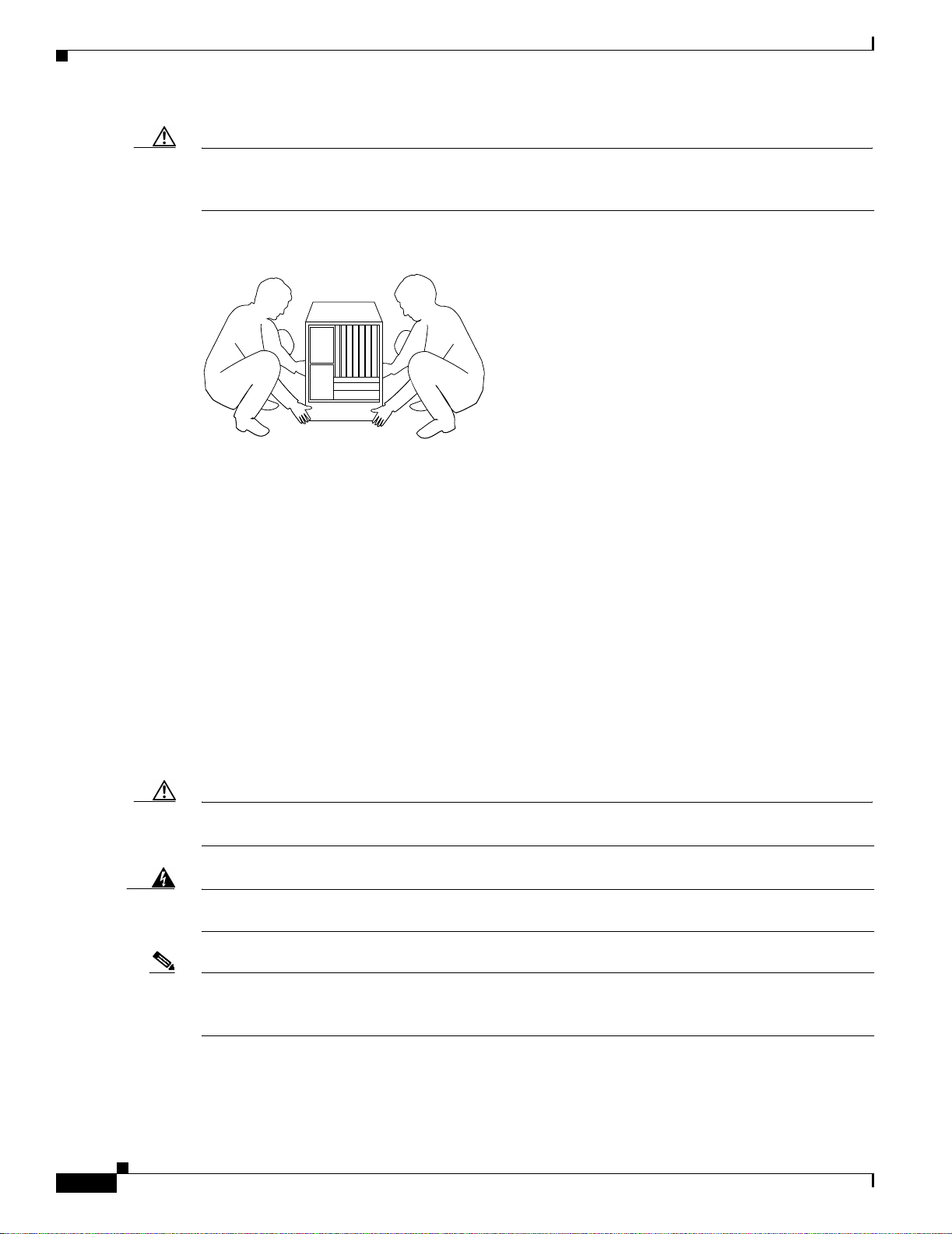
Safety Recommendations
Caution To prevent damage to the chassis and components, never attempt to lift the chassis by the plastic panels
on the front of the chassis, or by the handles on power supplies or processor modules. These panels and
handles were not d esign ed to sup por t the w eig ht o f the ch ass is.
Figure 2-1 Lifting Safe ly (Cisco 7507 Shown)
Chapter 2 Preparing for Installation
H2336
In general, whe never you lift a Cisc o 7500 se rie s c hassis, fo llow the se guid eline s:
• Whenever possible, avoid lifting the chassis alone.
• Ensure that your footing is solid, a nd balance the weight of the objec t betwee n your feet .
• Lift the chassis slowly; never move suddenl y or twis t y our b ody a s yo u lif t.
• Keep your back straight and lift with your l egs, not your back. If you must bend down to lift the
chassis, bend at the knees, not at the waist, to reduce the strain on your lower back muscles.
• Whenever possible, lift a chassi s fro m the bott om; gra sp th e und ersi de of t he c hassi s exteri or w ith
both hands.
• Always disconnect all external cabl es before lift ing or moving the c hassis.
• For the Cisco 7507, Cisco 7507-MX, Cisco 7513, Cisco 7513-MX, and Cisco 7576, we recommend
you lift the chassis with power supplies removed; use both han ds whe n handl ing the chassi s power
supply.
Caution To prevent damage, never attempt to lift or tilt the chassis with the handles on the interface processor
carriers. These handles are not designed to support the weight of the chassis.
Warning
A Cisco 7513 or Cisco 7576 chassis weighs approximately 160 lb (72.6 kg) fully configured. To prevent
injury, have someone help you lift the chassis.
2-4
Note We re commend that you reduc e the weight of the Cisco 751 3, Cisco 7513-M X, or Cisco 7576 by
removing the blower modul e, p roce ssor m odul es, power sup pli es, a nd c ard c age asse mbly be fo re
installation; however, this is not requir ed.
Cisco 7500 Series Installation and Configuration Guide
OL-5008-03 B0
Page 83
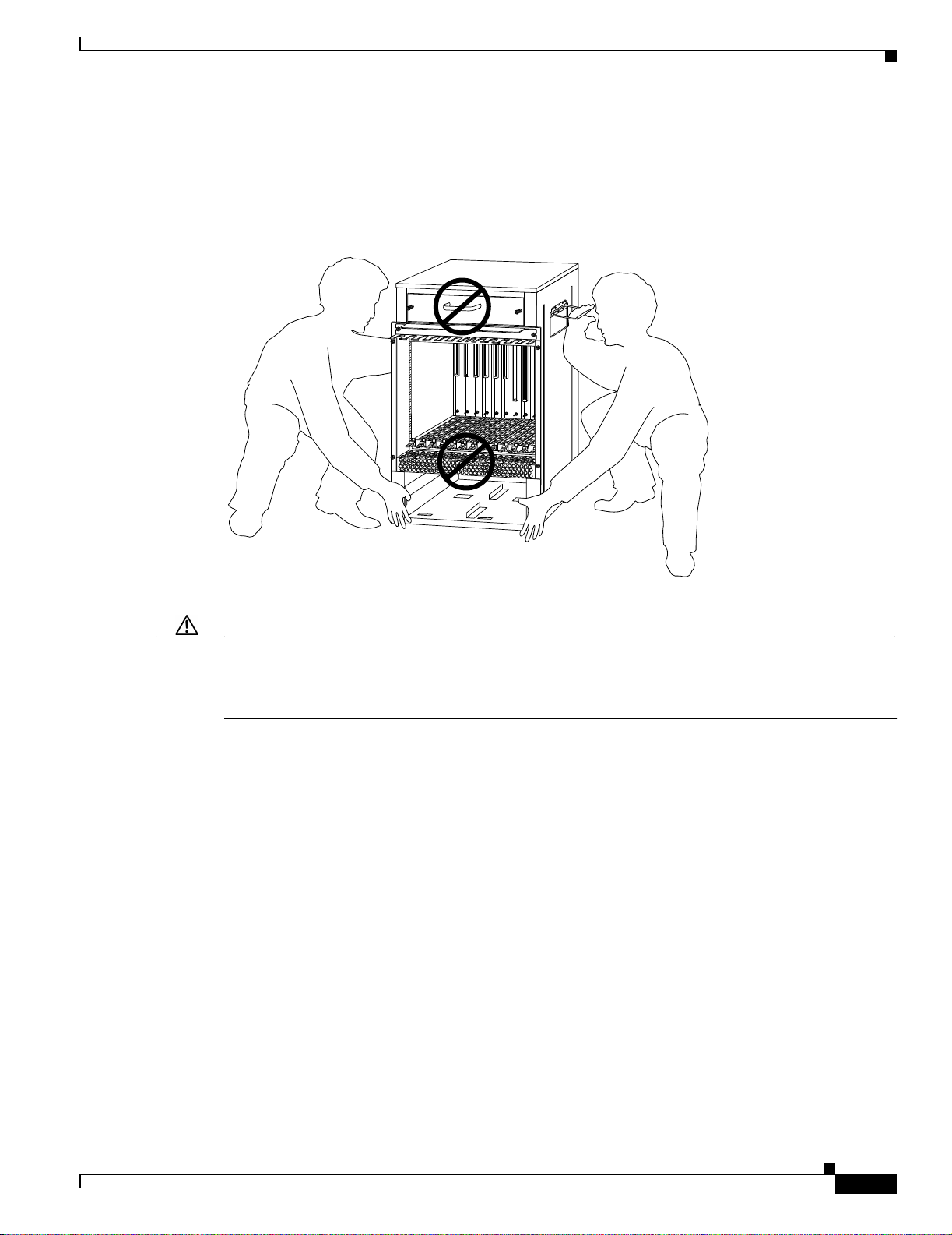
Chapter 2 Preparing for Installatio n
When you get ready to place th e Cisco 7513 , Cisco 7513-MX, or Cisco 75 76 into a rack or onto a
tabletop, each person shou ld lift it by graspin g the side ha ndle wit h one hand an d the bottom of the
chassis with the other , a nd lift the chassi s with your le g s, as sho wn in Figure 2-2. (Do no t lift the chassis
using the blower m odule h andl e or t he a ir in take vent b elow the c ard c a ge.)
Figure 2-2 Correct Way to Lift the Cisco 7513, Cisco 7513-MX, or Cisco 7576
Safety Recommendations
POWER
A
POWER
B
H3118
Caution To pre vent damage to the air intak e vent be low the c ard cage, do not lift the Cisco 7513, Cisco 7513-MX,
or Cisco 7576 by grasping the side handle with one hand and the bottom of the card cage with the other,
as shown in Figur e 2- 3. The air intake vent is not designed to support the weight of the chassis. Lift the
chassis as shown i n Figure 2-2.
OL-5008-03 B0
Cisco 7500 Series Installation and Configuration Guide
2-5
Page 84

Safety Recommendations
Figure 2-3 Incorrect Way to Lift the Cisco 7513, Cisco 7513-MX, or Cisco 7576
Chapter 2 Preparing for Installation
POWER
A
Preventing Electrostatic Discharge Damage
Electrostatic discharge (ESD) can damage equipment and impair electrical circuitry. It occurs when
electronic components are impro perly handled and can result in intermittent or complete failures.
Always ensure that the chassis is electrically connected to earth ground. Wear an ESD-preventive wrist
strap, ensuring that it makes good ski n contac t. To safely channel unwanted ESD voltages to ground,
connect the clip to an unpainted surface of the chassis frame. If no wrist strap is available, ground
yourself to the metal chassis.
Caution For safety, pe riodically check the resistance value of the ESD-preventive wrist strap, which should be
between 1 and 10 megohms.
POWER
B
H3119
2-6
Cisco 7500 Series Installation and Configuration Guide
OL-5008-03 B0
Page 85

Chapter 2 Preparing for Installatio n
AC-Input and DC-Input Power Guidelines
The wide-input AC-input power sup pli es i n the Cisco 75 00 se ries ro ut ers u se a power fact or c orr ect or
(PFC) that allows th e router to operate on input voltage and current within the AC-voltage range of 100
to 240 VAC and 50 to 60 Hz.
In Chapter 1, Table 1-1 (fo r th e Cisco 7505), Table 1-2 (for the Cisco 7507), Table 1-3 (for t he Ci sco
7507-MX), Table 1-4 (for the Cisc o 7513 ), Table 1-5 (for the Cisco 7513-MX), and Table 1-6 (for the
Cisco 7576) list system power specifications, including input voltage and operating frequency ranges.
The power supplies in the Cisco 7507, Cisco 750 7-MX, Cisc o 7513, Cisco 7513-MX, and Cisco 7576
routers have two safety interlock features as shown inFigure 2-4 . A locking device on each power supply
prevents the power supply from bei ng r em oved from t he ch assis w hen the power s upply sw it ch i s o n.
When the switch is in the on (|) position, a metal locking device extends into a slot in the chassis. When
the switch is in the of f (O) positi on, the l ocking d e vic e is raised an d cl ears the slot. Also, a r etention c lip
prevents the AC-input power supply power cable from being accidentally pulled out of the power supply
socket.
For additional po wer supply info rmation, se e the “AC-Input and DC-Input Power Guidelines” section on
page 2-7. Check the power at your site before installation and periodically after installation to ensure
that you are receiving clean p ower; install a power conditioner if necessary. We recommend that you
install a power conditioner b etw ee n the AC power source and the rou t er to help avoid problems cause d
by power spikes and brownouts, and to help protect agains t equipm ent dama ge fro m lightning st rikes.
We al so re c ommen d an un int errup tib le power s ource ( UPS) f or the r oute r to p rote ct agai nst p ower
failures at your site.
AC-Input and DC-Input Power Guidelines
Warning
This equipment is intended to be grounded. Ensure that the host is connected to earth ground during
normal use.
Figure 2-4 Power Supply Safety Interlocks (Cisco 7507 AC-Input Power Supply Shown)
O
Cable-retention clip
Safety interlock
switch
Cisco 7505 Power Considerations
The single 600W wide-inpu t AC-input power supply for the Cisco 7505 router uses a power factor
corrector (PFC) that allows the Cisco 7505 to operate on input voltage and current within the range of
100 to 240 VAC and 50 t o 60 Hz.
I
H1315a
Locking device
in ON and
locked positions
OL-5008-03 B0
Cisco 7500 Series Installation and Configuration Guide
2-7
Page 86

AC-Input and DC-Input Power Guidelines
The 600W DC-input power supply allows the Cisco 7505 to operate between –40 and –52 VDC in North
America (–48 VDC nominal) a nd bet wee n –56 and –72 VDC in the European Union (–60 VDC
nominal). We recommend that y ou use a n 8-AWG, highly flexible str an ded ca bl e fo r th e D C p ower
connections. (See Table 1-1 for a list of Cisco 7505 power specifications.)
Note The Cisco 7505 installation must comply with all applicable codes and is approved for use with copper
conductors only. The ground bond fastening hard ware should be of compati ble mate rial and pr eclude
loosening, deterioration, and electrochemical corrosion of hardware and joined material. Attachment of
the chassis ground t o the cent r al o ffice or other i nte rior ground sys tem sho uld b e made w ith a 6- AWG,
copper ground conductor a t a minimum. Th e Cisco 7505 c hassis employs two threa ded M5 chassi s
grounding receptacle s, whic h are intend ed to be bond ed direc tly to the cen tral office or other interi or
ground system. These receptacles are located on the rear of the chassis. The chassis ground requires M5
screws and locking hardware, w hich are not incl uded .
Cisco 7507 and Cisco 7507-MX Power Considerations
The 700W AC-input power supply for the Cisco 7507 and Cisco 7507-M X routers use s a power factor
corrector (PFC) that allows it to operate on input voltage and current within the range of 100 through
240 VAC and 47 through 63 Hz. The 700 W DC-inpu t power supply allows the Cisco 7507 and Cisco
7507-MX to op erat e b et we en –40 and –72 VDC (–48 VDC nominal). We recommend that you use an
8-AWG , high ly flexibl e str an ded ca ble fo r th e D C p ower conn ect ions. ( See Table 1-2 and Table 1-3for
a list of Cisco 750 7 a nd Cisc o 750 7-M X p ower spec ifications.)
Chapter 2 Preparing for Installation
Note The Cisco 7507 or Cisc o 750 7-MX in stall ation m ust c om ply with a ll ap pl icabl e c odes an d is ap proved
for use with c opp er c on duct ors only. The ground bon d fa steni ng h ar dware sh ould be o f c om pat ible
material and preclu de loose ning, de terio ration, and elec troche mical corrosi on of hard ware and join ed
material. Attac hmen t of the c hassi s grou nd to t h e ce ntr al office or othe r int erio r gro und sy stem sho uld
be made with a 6- AWG, copper ground co ndu cto r a t a mi nimu m. The Cisc o 7507 a nd Cisc o 750 7-MX
chassis employs two thr eade d M5 cha ssis g rou nding r ecept acles, wh ich ar e i nte nded to b e bon ded
directly to the central office or other interior ground system. These receptacles are located on the rear of
the chassis. The chassis gro und req uires M5 screws and lock ing hardwa re, whic h are not incl uded .
A second, identical power supply is also present in routers configured with the redundant power option;
this ensures that power to the chassis co ntin ues uninter r upted if one power supply fails. It also provides
uninterrupted power if the input power line fails, but only if the po wer supplies are c onnected to separate
input lines.
Whenever possible, provide redundant power sources for each power supply installed in the chassis. For
AC-input installations, install an uninterruptible power source where possible. Install proper grounding
to avoid damage from lightning and power surges.
If only one input line is available, and you must connect both power supplies to the same source, the
redundant power supply will provide continuous power if the first power supply fails. It cannot provide
power backup if the input power fails.
Warning
This unit might have more than one power cord. To reduce the risk of electric shock, disconnect the
two power supply cords before servicing the unit.
2-8
Cisco 7500 Series Installation and Configuration Guide
OL-5008-03 B0
Page 87

Chapter 2 Preparing for Installatio n
AC-Input and DC-Input Power Guidelines
Cisco 7513, Cisco 7513-MX, and Cisco 7576 Power Considerations
The 1200W AC-input power supply in the Cisco 7513, Cisco 751 3-MX, an d Cisco 7576 ro uters us es a
power factor corrector (PFC) that allows it to operate on input voltage and current within the range of
100 through 240 VAC and 47 through 63 Hz. Follow these precaution s and rec ommenda tions when
planning power connect ions to t he rou ter. (See Table 1-4 for a l ist of C isco 751 3 power spe cifications,
Table 1-5 for a list of Cisco 7513-MX power specifications, and Table 1-6 for a list of Cisco 7576
power specifications.)
Note Wiring codes prevent 20A plugs from being us ed w ith m ost equ ipme nt ra ck power strips. T he C isco
7513, Cisco 7513-MX, or Cisco 7576 install ation must comp ly with all applicab le codes. Th e ground
bond fastening hardware should be of compa tible ma terial an d preclu de looseni ng, de teriora tion, and
electrochemical corrosion of hardware and joined material. Inst allation is approved for use with copper
conductors only. Attachment of t he c ha ssis gr oun d re cept acl es to t he c ent ral office or oth er i nte rior
ground system should be made with a 6-AWG, copper ground conductor at a minimum. The Cisco 7513,
Cisco 7513-MX, and Cisco 7576 chassis employ two threaded M5 chassis grounding receptacles. These
receptacles ar e int end ed t o be bond ed d irect ly t o the ce nt ral office or oth er int eri or g rou nd syste m an d
are located on the rear of the chassis. The chassis grounding recep tac les requir e M5 screws and locking
hardware, which a r e not incl u ded .
Warning
A second, identical power supply is also present in routers configured with the redundant power option;
this ensures that power to the chassis continues uninterrupted if that one power supply fails. It also
provides uninterrupted power if the input power line fails, but only if the power supplies are connected
to separate input lines.
Whenever possible, provide redundant power sources for each power supply installed in the chassis. For
AC-input installations, install an uninterruptible power source where possible. Install proper grounding
to avoid damage from lightning and power surges.
If only one input line is available, and you must connect both power supplies to the same source, the
redundant power supply will p rovide continuous power if the first power supply fail s . It cannot provide
power backup if the input power fails.
This unit might have more than one power cord. To reduce the risk of electric shock, disconnect the
two power supply cords before servicing the unit.
An AC-input-powered Cisco 7513, Cisco 751 3-M X, or Cisc o 7576 o pe ratin g at 120 VAC requires a
minimum of 20A service, with a 20A rec eptac le at the power source. The power cable supp lied with the
chassis uses a 20A plug. Figure 2 -5 shows cable feature s requir ed to conne ct the 20A plug to your AC
source.
OL-5008-03 B0
Cisco 7500 Series Installation and Configuration Guide
2-9
Page 88

Plant Wiring Guidelines
Chapter 2 Preparing for Installation
Figure 2-5 20A AC-Input Power Cable Connector, Plug, and Receptacle (Cisco 7513,
Cisco 7513-MX, and Cisco 7576)
H3164
IEC 320 20-amp connector
(to the AC power supply)
20-amp plug 20-amp receptacle
The DC-powered chassis requires a minimum 35A dedicated service (at –48 VDC). We recommend that
you use an 8-AWG, highly flexible stranded cable for the DC power connections. Figure 2- 6 shows the
conductor pre para tio ns.
Figure 2-6 DC-Input Pow er Cable Conne ction to Terminal Block (Cisco 7513, Cisco 7513-MX, and
Cisco 7576)
.925
.83
End View
.39
.140
.210
Maximum exposed
conductor surface
.610
Crimp area
Plant Wiring Guidelines
This section provides guidelines for settin g up the plan t wiring an d cabli ng at you r site. When plannin g
the location of the new system, consider wiring issues, distance limitations for signaling,
electromagnetic interference, and connector compatibility, as described in the sections that follow.
Interference Considerations with Cabling
When wires a re r un for a ny signi ficant dist an ce i n an el e ctro ma gn etic field, in te rf eren ce c an oc cur
between the field and the signals on the wires. This fact has two implications for the construction of plant
wiring:
• Bad practices can result in radio interference emanating from the plant wiring.
All measurements in inches
8-AWG conductor
H3814
2-10
• Strong electromagnetic interference (EMI), especially as caused by lightning or radio transmitters,
can destroy the sig nal d ri v ers a nd r ecei v er s in th e route r, and can even cr eate an e lect rical h azar d b y
conducting power surges through lines and into equipment. (Review the safety warnings in the
“Safety Recommendations” section on page 2-2.)
Cisco 7500 Series Installation and Configuration Guide
OL-5008-03 B0
Page 89

Chapter 2 Preparing for Installatio n
Note To predict and remedy st rong EMI, you might ne ed to consult exper ts in radio freq uency
If you use twisted-pair cable in your plant wiring with a good distribution of ground ing conductors, the
plant wiring is unlikely to emit radio interference. When exceeding the recommended distances, use a
high-quality twisted-pair cable with one grou nd c onducto r for each data signa l.
If wires exceed recommen ded distanc es, or if wir es pass betwe en buildings, give special cons iderati on
to the effect o f a lig h tning strike in your vicinity. The electromagnetic puls e (EM P ) ca us e d by lightning
or other high-energy phenomena can easily couple enough energy into unshielded conductors to destroy
electronic devices. If yo u h ave had pro blem s o f t his so rt in the past , yo u m ight wan t t o con sul t expe rts
in electrical surge suppression and shielding.
Most data centers cannot resolve the infrequent but potentially catastro phic problems just described
without pulse meters and other special equipm ent. These problems can cost a great deal of time to
identify and resolve, so take precautions by providing a properly grounded and shielded environment,
with special attention to issues of electrical su rge suppression.
Plant Wiring Guidelines
interference (RFI).
Warning
Warning
Warning
When stranded wiring is required, use approved wiring terminations, such as closed-loop or
spade-type with upturned lugs. These terminations should be the appropriate size for the wires and
should clamp both the insulation and conductor.
T o be installed and maintained by service personnel as defined by AS/NZS 3260. Incorrect connection
of this or connected equipment to a General Purpose Outlet could result in a hazardous situation. The
telecommunication lines must be disconnected before unplugging the main power connection and
while the housing is open.
Never defeat the ground conductor or operate the equipment in the absence of a suitably installed
ground conductor. Contact the appropriate electrical inspection authority or an electrician if you are
uncertain that suitable grounding is availabl e.
Distance Limitations of Interface Cabling
The length of your networks a nd the dista nce betwe en conne ctions depend on the ty pe of signal, the
signal speed, and the transmission media (the type of cabling used to transmit the signals). For example,
standard coaxial cable has a greater channel capacity than twisted-pair cabling.
The distance and rate limits for the a v aila ble elect rical interfac es supported b y Cisco 750 0 series routers
are recommended maxi mum spe eds and dista nces for signal ing. If you unders tand the elec tric al
problems that might arise and can compensate for them, you might get good results with faster rates and
greater distances ; however, do so at your own risk .
OL-5008-03 B0
Note We re co mm end tha t y ou do no t exceed specified transmission rate and distance limits for interface
cabling.
For complete information on recommended maximum speeds and distances for signaling and interface
Cisco 7500 Series Installation and Configuration Guide
2-11
Page 90

Chapter 2 Preparing for Installation
Site Environment, Chassis Temperature, and Airflow Guidelines
specifications for the electrical interfaces supported by the Cisco 7500 series routers, refer to the
companion publication Interface Processor Installation and Configuration Guide .
Site Environment, Chassis Temperature, and Airflow Guidelines
Cisco 7500 series routers can opera te as standal one systems pl aced on a table or as rack-m ounted
systems in a data proc essi ng or l ab e nvironment. (We recommend rack-mounti ng for a ll Ci sco 750 0
series routers.)
The internal fan or blower operates so that it maintains an acceptable operating temperature inside the
chassis. The router requi re s a dry, clean, well-ventilated , and air-conditioned environment. The in ter nal
blower pulls ambien t air thr ough the chassis to cool the internal comp onents. To allow suff icie nt airflo w,
maintain a mini mum of 2 i nch es (5. 08 cm) of cl eara nc e a t bo th t he in let and exha ust openi ng s on the
chassis. If the airflo w is blocked or restricted, or if the inle t air is too warm, an ov ertemperature conditio n
can occur. Under e xtrem e conditions, th e environmental monitoring system will shut down the power to
protect the syst em c om pon en ts.
T o help maintain normal operation and avoid unnecessary maintenance, plan your site configuration and
prepare your site before installation. After installation, make sure that the site maintains an ambient
temperature of 32 through 10 4°F (0 through 40°C), and keep the ar ea around the chassi s as free fro m
dust as is practical. For a description of the environmental monitor and status levels, see the
“Environmental Monitori ng a nd Repor tin g Overv iew for the Cisc o 7500 Series” section on page 2-22.
If the temperature of the air drawn into the chassis is higher than desira ble, the ai r tempe ratur e inside
the chassis m i gh t a l s o be t o o h i g h . T his condition can occur w hen the wiring closet or rack in which the
chassis is mounted is not ventilated properly, when the exhaust of one device is placed so it enters the
air inlet vent of the chassis, or when the chassis is the top unit in an unventilated rack. Any of these
conditions can inhibit airflow and create an overtemperature condition.
Because the inlet air flows into one part of the chassis and out another, other devices can be
rack-mounted with as little as 1 inch (2.54 cm) of clearance abo ve and belo w the cha ssis. Howe ver , whe n
mounting a router in a rack with ot her equipm ent , or when plac ing it on a table w ith other equipme nt
located close by, ensure that the exhaust from other equipment does not blo w into the inlet of the ch assis.
The inlet air is drawn in and exhausted as shown in Figure 2-7 (for the Cisco 7505), Figure 2-8 (for the
Cisco 7507 and Cisco 7507-MX), and Figure 2-9 (for the Cisco 7513, Cisco 7513-MX, and Cisco 7576).
Table 2-1 lists the operating and nonoperating environmental site requirements. To maintain normal
operation and ensure high syste m a v ail ability, maintain an ambient temperat ure a nd clean p o wer at your
site.
The ranges in Table 2-1 are those within which the router will continue to operate; however, a
measurement th at is a ppr oach i ng the min im um or m ax imum o f a ra nge i n dica tes a po ten tial pr oble m.
You can maintain normal operation by anticipating and correcting environmental anomalies before they
approach the maximum operating range.
Table 2-1 Environmental Specifications for the Cisco 7500 Series Routers
Specifications Minimum Maximum
Temperature, ambient op er ati ng 32°F (0°C) 104°F (40°C)
Temperature, ambient nonoper ating and
storage
Humidity, ambient (noncondensing )
operating
–4°F (–20°C) 149°F (65°C)
10% 90%
2-12
Cisco 7500 Series Installation and Configuration Guide
OL-5008-03 B0
Page 91
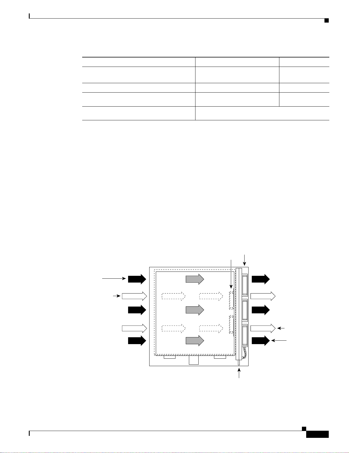
Chapter 2 Preparing for Installatio n
Table 2-1 Environmental Specifications for the Cisco 7500 Series Routers (continued)
Specifications Minimum Maximum
Humidity, ambient (noncondensing )
nonoperating and storage
Altitude, operating and nonoperating Sea level
Vibration, operating 5 to 200 Hz, 0.5 g1 (1 octave per
Vibration, nonoperating 5 to 200 Hz, 1 g (1 octave per minute)
1. g = force of gravity; 32 ft/sec2.
Cisco 7505 Airflow Considerations
In the Cisco 7505, six individual axia l fans draw co oling a ir th rough t he ch as sis int eri or to main tain a n
acceptable temp era ture f or th e int ern al com pone nts. Th e fans dr aw ai r in t hr ough t he inl et vents o n th e
side of the chassis opposite the fans, acro ss the proce ssor modules an d other internal compo nents, an d
through the exhaust vents adjacent to the fans.
Site Environment, Chassis Temperature, and Airflow Guidelines
5% 95%
10,000 ft (3050 m)
–
minute)
200 to 500 Hz, 2 g (1 oc tave per minute) –
The sides of the chassis must remain unobstructed to ensur e adequate airflow and prevent overheating
inside the chassis. A temperature sensor on the RSP monitors the inter nal air temperature. The power
supply has two fans for cooling.
Figure 2-7 shows the chassis fans an d a irf low throug h the Cisco 75 05.
Figure 2-7 Airflow Through the Cisco 7505
Top view of router
Power supply fans
Interface processor end
Chassis
airflow
Power supply
airflow
Chassis fans
Power supply
airflow
Chassis
airflow
OL-5008-03 B0
H2000
Service (noninterface processor) end
Fan tray
Cisco 7500 Series Installation and Configuration Guide
2-13
Page 92

Site Environment, Chassis Temperature, and Airflow Guidelines
Cisco 7507 and Cisco 7507-MX Airflow Considerations
The system blower on t h e Ci sco 7 507 a nd Cisc o 7 507-M X provide s coo l ing a ir fo r th e pro cessor
modules. The blower draws air in through the air filter in the front chassis panel and directs it up through
the floor of t he intern al sl ot co mpar tmen t and o v er t he ca rds. The e x haus t air i s for ced o ut th e re ar o f the
chassis above and to each side of the pro cessor slots. The blo wer needs a clean air f ilte r in order to dra w
in suffic ient amount s of coolin g air; e xcessi ve d ust in the f ilter will restri ct the airf low. Keep the air filt er
clean and replace it when necessary.
Figure 2-8 shows the syst em blower a nd air flow throu gh the Cisc o 7507 a nd Cisc o 7507-M X.
Figure 2-8 Airflow Through the Cisco 7507 and Cisco 7507-MX
Top view of router
System
blower
Front of
chassis
Air dam
Chapter 2 Preparing for Installation
6
5
4
3 (RSP2)
2 (RSP2)
1
0
Air dam
Power
supplies
Rear of
chassis
H3882
Sensors on the RSP2 (for example) monitor the inlet and internal chassis air temperatures. If the air
temperature at ei the r of the se nsors exc eeds a desi red th resho ld, an environmenta l m onitor di splays
warning messages and can interrupt syste m operation to protect the syste m compone nts from possibl e
damage from excessive heat or electrical current.
The power supplies have their own fans. An air dam between th e power supply bays and the process or
module compartment keeps the airflow constant.
Cisco 7513, Cisco 7513-MX, and Cisco 7576 Airflow Considerations
The blower on the Cisco 7513, Cisco 7513- MX, and Cisco 7576 provid es cooling ai r for the processor
modules. The exhaust air is forced out the front of the chassis behind the card cage.
Figure 2-9 shows the syst em blower a nd air flow throu gh the Cisc o 7513 , Ci sco 7513 -M X, a nd Cisc o
7576.
2-14
Cisco 7500 Series Installation and Configuration Guide
OL-5008-03 B0
Page 93

Chapter 2 Preparing for Installatio n
Figure 2-9 Airflow Through the Cisco 7513, Cisco 7513-MX, and Cisco 7576
System blower
Card cage
Equipment Rack-Mounting Guidelines
Intake air Exhaust air
Power supplies
The power supplies have their own fans with airflow that is independent of the chassis airflow. Ensure
that there is minimum front and back clearance of 6 inches (15.24 cm).
Equipment Rack-Mounting Guidelines
This section provides the equipmen t rack-moun ting guidelin es that must be obser ved before installin g a
Cisco 7500 series r out er in a n equi pm ent rac k.
General Equipment Rack Ventilation Considerations
If you plan to i nstal l the rou t er i n an equi p ment r ack, y ou can avoid overtemper a ture cond i tio ns by
observing the following p recaut ion s:
• There must be a t least 2 inches (5.08 cm) of clearan ce between each side of the chassis an d the side
(or inner wall) of an enclosed rack.
H3093
OL-5008-03 B0
• Enclosed racks must have adequate ventilation or an exhaus t fan; use an open rack whenever
possible.
• A ventilation system that is too powerful in a closed rack can also prevent cooling by creating
negative pressure around the chassis and redirecting the air away from the inlet vents. If necessary,
operate the chassis with the rack open.
• The correct us e of baffles in an encl osed rack ca n help to ens ure th at co ol air re aches the ch assis.
Cisco 7500 Series Installation and Configuration Guide
2-15
Page 94

Equipment Rack-Mount ing Guidelines
• Equipment near the bottom of a rack can genera te excessive heat that is drawn upward and into the
inlet ports of equipment above, leading to overtemperature conditions in devices at or near the top
of the rack.
In addition, the following sections contain specific rack-mounting guidelines for the Cisco 7500 series
routers:
• Cisco 7505 Rack-Mou nt Co nside rati ons, p age 2-16
• Cisco 7507 and Cisc o 7507 -M X Ra ck-M ount Consi dera tions, p age 2-18
• Cisco 7513, Cisco 7513- MX , a nd Cisco 757 6 R ack- Mo unt C onsid er ations , pag e 2-20
Cisco 7505 Ra ck-M ou nt Cons ide ra tions
The rack-mountin g hardware included w ith the Cisco 75 05 is suitabl e for most 19- inch (48. 26-cm)
equipment racks o r 2-p ost r acks. Th e r oute r ch as sis mount s to two po sts or r ails i n the rac k w ith two
mounting ears, which attach to the sides of the chassis. Ideally, you should be able to access both the
interface processor a nd n oninte rfac e pr oc es sor en ds of the ro ute r wit ho ut having t o rem ove it from t he
rack. Before using a part icular ra ck, ch eck for obst ructi ons (such as a power stri p) that coul d impair
access to the int erfac e proces sors or ch ass is cover panel .
Chapter 2 Preparing for Installation
As an alternat ive, the r oute r ca n be m oun ted on a n eq ui pment shel f p rovided t hat the r ack dim ens ions
allow the router to be secured to the shelf, and the overall configuration permits safe installation and
access. Figure 2-10 shows the chassis footprint and outer dimensions.
To use the rack-mounting hardware provided with the router, consider the following guidelines:
• To mount the router between two posts or rails using the mounting ears, the inner clearance (the
width between the inner sides of the two posts or rails) must be at least 17.72 inches (45 cm).
• The height of the chassis is 11 inches (27.94 cm) with the chassis feet attached, and 10.5 inches
(26.67 cm) when the chassis feet are removed.
• When mounti ng the r outer i n four -post or 2- post r acks, be sure to use all eight of the scre ws p rovid ed
to secure the chassis ears to the rack posts (use four screws per ear). The ears secure one end of the
chassis to two rack posts; the rest of the chassis is cantilevered off the posts. Using fewer than all
eight screws might not b e sufficient to s uppo rt t h e w eigh t of the c hassi s.
• If the rack has a vertical power strip or other obstacle, ensure that there is sufficient clearance to
install and remove proc es sor modul es, wh ich mu st b e pul le d str aigh t ou t of the ir slot s.
2-16
Cisco 7500 Series Installation and Configuration Guide
OL-5008-03 B0
Page 95

Chapter 2 Preparing for Installatio n
Equipment Rack-Mounting Guidelines
2 in.
(5.08 cm)
Chassis depth
19.0 in. (48.26 cm)
management bracket
Chassis depth with power cord and cable
Fan tray
17.0 in. (43.18 cm)
Chassis foot C
14.25 in. (36.20 cm)
Power supply width
14.60 in. to ears (37.08 cm)
Noninterface processor end
Interface processor end
Interface processor width
14.55 in. (36.96 cm)
Chassis width
17.50 in. (44.45 cm)
1.25 in. (3.18 cm)
Chassis foot C
Power supply depth
11.25 in. (28.58 cm)
Interface processor depth
H2818
13.32 in. (33.83 cm)
12.00 in. (30.48 cm)
Figure 2-10 Chassis Footprint and Outer Dimensions (Cisco 7505)
Caution To prev ent chassis o ver heating, ne v er install the r outer in an enc losed rack that is n ot properly v entilated
or air-conditioned.
When planning your Cisc o 7505 r ack inst alla tio n, c onside r the f oll owing guide line s:
• Install the router in an open rack whenever possible. If installation in an enclosed rack is
unavoidable, ensure that the rack has adequate ventilation.
• Allow sufficient clearance aroun d the rack for maintenance. If the rack is mobile, you can push it
back near a wall or cabinet for normal operation and pull it out when necessary for maintenance
(installing or movin g i nte rface p roce ssor s, conne cti ng ca bles, o r repl aci ng or up gr adin g
components).
• Maintain a minimum clearance of 2 inches (5.08 cm) on each side of the chassis for the cooling air
inlet and exhaust ports. Avoid placing the router in an overly congested rac k or direct ly next to
another equipment rack. Otherwise, the heated exhaust from other equipment can enter the inlet air
vents and cause an overtemp er atur e c ond ition in side th e ro uter.
• Install and use the cable -management b rackets included with the router to ke ep cables or ganiz ed and
out of the way. Consider the equipment and cabling that is already installed in the rack. Ensure that
cables from other equipment will not impair access to the interface processors or require you to
disconnect cables unn ec essar il y to pe rform e qu ipme nt m a inten ance o r u pgrad es.
• Install heavier equipment in the lower half of the rack to maintain a low center of gravity.
OL-5008-03 B0
Cisco 7500 Series Installation and Configuration Guide
2-17
Page 96

Equipment Rack-Mount ing Guidelines
• If you plan to use an equipment shelf, ensure that the shelf is constructed to support the weight and
dimensions of the chassis. Figur e 2-10 shows the chassis footprint, which you will need if you are
designing a customized she lf.
• If you use 2-post racks, be sure that the rack is bolted to the floor and secured. One end of the chassis
mounts to the two rack posts with the chassis ears, and the rest of the chassis is cantilevered off the
posts. Ensure that the weig ht of the chassis does not make the rack unstable. Some 2-post racks are
also secured to ceil ing brackets if warr anted by the we ight of the eq uipm ent i n the ra ck.
In addition to the preced ing guidel ines, we recomm end you review the preca utions for avoiding
overtemperature conditions in the “General Equipment Rack Ventilation Considerations” section on
page 2-15.
Cisco 7507 and Cisco 7507-MX Rack-Mount Considerations
An optional rack-mounting kit is available for mounting the Cisco 7507 or Cisco 7507-MX in a standard
19-inch (48.26 cm) e quipm ent r ack. T he m ountin g k it is no t sui ta ble fo r use w ith 2 -po st e quipm e nt
racks, or those wit h ob struc tions (suc h as a power strip) th at cou l d im pair ac cess to the in terfa ce
processors and power supplies. In telco environments or at installation sites that use nonstandard racks,
the router can be mounte d on an equip ment sh elf, provid ed that the rack dim ensions al low safe
installation and access to the power supplies and interface processors. Figure 2-11 shows the chassis
footprint and outer dime nsions.
Chapter 2 Preparing for Installation
To use the optional rack-mount kit, your equipment rack must meet the following requirements:
• The width of the ra ck, be twee n th e two f ron t m ounti ng str ips or r ail s, must b e 17. 75 inches (45.09
cm).
• The depth of the rack, betw een the front and re ar moun ting strip s, must be at least 19.25 inches
(48.90 cm) but not more than 32 inches (81.28 cm ).
• The height of the chassis is approximately 20 inches (50.08 cm) (19.25 inches [48.90 cm] when the
chassis feet are remo v ed ). Th e rack mus t ha v e sufficient vertical cleara nce t o insert the chass is and,
if required after installation, to remove the chassis feet.
• If the rack has a vertical power strip or other potential obstacle, ensure that it will allow sufficient
clearance to install and re move both interface proc essors (11 inches [27.94 cm] deep) an d power
supplies (16 inc hes [ 40.64 c m] de ep), b oth of whi ch m ust b e pul le d str aig ht o ut of the ch assi s.
2-18
Cisco 7500 Series Installation and Configuration Guide
OL-5008-03 B0
Page 97

Chapter 2 Preparing for Installatio n
Figure 2-11 Chassis Footprint and Outer Dimensions (Cisco 7507 and Cisco 7507-MX)
Equipment Rack-Mounting Guidelines
Power supply/interface processor end
1.220 in.
Foot diameter
1.125 in.
4 places
Foot thread
size 5/16 in.
4 places
10 in. clearance required for
interface processor removal
13 in.
16 in. clearance required
for power supply removal
4 in.
16 in.
(28 in. including
power cord)
5.095 in.
25 in.
16.916 in.
15.060 in.
17.5 in.
Plastic front panel end
H9716
Caution To prevent overheating, never install the router in an enclosed rack that is not properly ventilated or air
conditioned.
When planning your Cisco 7507 or Cisco 7507-MX rack installation, consider the following guidelines:
• Allow at least 3 to 4 feet (0.91 to 1.22 m) of clearance behind the rack for maintenance. If the rack
is mobile, you can push it back w it hin 1 fo ot (0 .3 m ) o f a wal l or cab in et for no rm al o pera tio n an d
pull it out when necessar y for mainte nance (i nstallin g or replac ing inte rface proc essors or power
supplies, or conne cting ne twork c abl es or int erfac e un its) .
• The ports for cooli ng ai r are loca ted on t he fro nt and re ar of the c has sis, so m ul tip le ro uter s ca n be
rack-mounted with little or no vertical clearance. However, avoid placing the router in an overly
congested rack.
• Consider the equipment and cabling that is already installed in the rack. Ensure that cables from
other equipment will not obst ruct the airflow through the chassis or impai r access to the power
supplies or interfac e pr oc essors. Ro ute c ables away f rom field -r eplac eabl e c ompone nts t o avoid
having to disconnect c abl es un nece ssa rily t o pe rf orm equ ipme nt ma inten an ce o r upg ra des.
• Install heavier equipment in the lower half of the rack to maintain a low center of gravity.
OL-5008-03 B0
Cisco 7500 Series Installation and Configuration Guide
2-19
Page 98

Chapter 2 Preparing for Installation
Equipment Rack-Mount ing Guidelines
• If you plan to use an equipment shelf, ensure that the shelf is constructed to support the weight and
dimensions of the chassis . Figure 2- 11shows the chassis footprint, which y ou will need if you are
designing a customized she lf.
• Install the router in an open rack whenever possible. If installation in an enclosed rack is
unavoidable, ensure that the rack has adequate venti lation or an exhaus t fan.
• To p ro per ly in st all t he Ci sco 75 07 or Cisc o 750 7-M X i n a ra ck, use th e instru ct ions in the
configuration note Cisco 7000 and Cisco 7507 Rack-Mount Kit Installation Instructions (Document
Number 78-1058- xx , wh er e xx indic ate s th e lat est do cume nt vers io n) tha t a ccom pa nies t he
rack-mount kit. The ra ck-moun t kit for the Cisco 7507 an d Cisco 7507- MX is the same kit
(ACS-7000RMK=) as the rack- mou nt k i t fo r th e Cisco 7 513, C is co 7513- MX , a nd Cisco 7 576 .
In addition to the preced ing guidel ines, we recomm end you review the preca utions for avoiding
overtemperature conditions in the “General Equipment Rack Ventilation Considerations” section on
page 2-15.
Cisco 7513, Cisco 7513-MX, and Cisco 7576 Rack-Mount Considerations
The rack-mounting hardware included with the Cisco 7513, Cisco 7513-MX, and Cisco 7576 is suitable
for most 19-inch equi p ment r ack s an d 2-p ost r acks. I deall y, you should be abl e t o acce ss bo th t he
interface processor and noni nterface processo r ends of the ro uter wit hout having to remove the chas sis
from the rack.
The router can be mounted in the rear of a rack. Before using a particular rack, check for obstructions
(such as a power strip) that could impair rack-mount installation. If a power strip does impair a rear
rack-mount installation, remove the power strip before installing the router in the rack and then replace
it after the chassis is installed. As an alternative, th e router can be mounted on an equipment shelf
provided that the shelf and rack dimensions allow the router to be secured to the shelf and the overall
configuration permits safe installation and access; however, we recommend rack-mount instal l ation for
the Cisco 7513, Cisco 7513-MX, and Cisco 7576. Figure 2-12 shows the chassis footpri nt and ou ter
dimensions.
2-20
To use the rack-mounting hardware provided with the router, consider the following guidelines:
• To mount the router between two posts or rails using the mounting ears, the inner clearance (the
width between the inner sides of the two posts or rails) must be at least 17.72 inches (45 cm).
• The height of the chassis is 33. 75 inches (85.725 c m).
• When mounting the r out er in fo ur-post or 2-post rac ks, be sur e to use all of the s cr ews provided to
secure the chassis to the rack posts. Using fewer than all the screws provided in the rack-mount kit
might not be sufficient to support the weight o f the chassis.
• If the rack has a vertical power strip or other obstacle, ensure that there is sufficient clearance to
install and remove proc es sor modul es, wh ich mu st b e pul le d str aigh t ou t of the ir slot s.
Cisco 7500 Series Installation and Configuration Guide
OL-5008-03 B0
Page 99

Chapter 2 Preparing for Installatio n
Figure 2-12 Chassis Footprint a nd Out er Dimens ions (Cisco 7513, Cisco 7513-MX, an d Cisco 7576)
19 in. required
for blower removal
18.93
in.
1.75 in. 4 places
12.73 in.
Equipment Rack-Mounting Guidelines
3.94 in.
1.47
in.
14.57
in.
17.50
in.
Plastic front
panel end
18.75
in.
21.23
in.
H3178
Caution To prevent chassis overheating, never install the router in an enclosed rack or room that is not prop erly
ventilated or air-conditioned.
When planning your Cisco 7513, Ci sco 7513-M X, or Cisco 7576 ra ck install ation, co nsider the
following guidelines:
• Install the router in an open rack whenever possible. If installation in an enclosed rack is
unavoidable, ensure that the rack has adequate ventilation.
• If you plan to use an equipment shelf, ensure that the shelf is constructed to support the weight and
dimensions of the chassis . Figure 2-12 shows the chassis footprint, which you will need if you are
designing a customized shelf. We recommend that you use the rack-mount kit designed for the Cisco
7513, Cisco 7513-M X, an d C isco 75 76.
• Allow sufficient clearance aroun d the rack for maintenance. If the rack is mobile, you can push it
back near a wall or cabinet for normal operation and pull it out when necessary for maintenance
(installing or movin g i nte rface p roce ssor s, conne cti ng ca bles, o r repl aci ng or up gr adin g
components). Otherwise, allow 19 inches (48.3 cm) of clearance to remove the blower module,
power supplies, and processor modules.
OL-5008-03 B0
Cisco 7500 Series Installation and Configuration Guide
2-21
Page 100

Environmental Monitorin g and Reporting Overview for the Cis co 7500 Series
• Maintain a minimum clearance of 6 inches (15.24 cm) on the rear and front of the chassis for the
cooling air inlet and exhaust ports, respectively. A v oid placing the router in an overly congested rack
or directly next to another equipment rack. Otherwise, the heated exhaus t air from other equipment
can enter the inlet air vents and cause an overtemperature condition inside the router.
• Install and us e th e ca ble management bracket included with the router to keep cable s o rganized and
out of the way of proce sso r m odul es, p ower suppli es, an d the blower modu l e. Co nside r t he
equipment and c abling t hat is al read y insta lled in the r ack. En sure t ha t cable s fr om oth er eq uipm ent
will not impair access to the interface processors or require you to disconnect cables unnecessarily
to perform equipmen t mainte nance or up grade s.
• Always install he avier equipment in the lower half of a rack to maintain a low center of gravity to
prevent the rack from falling over. If you install one Cisco 7513, Cisco 7513-MX, or Cisco 7576 in
a rack, the chassis bottom should not be higher than 20 inches (50.8 cm) from the floor.
• If you use 2-post racks, be sure that the rack is bolted to the floor and secured. One end of the chassis
mounts to the two rack posts wit h the chassis ears; t he rest of the chassis is c antilev ered off the posts.
Ensure that the weight of the chassis does not make the rack unstable. Some 2-post racks are also
secured to ceiling brackets if warranted by the weight of the equipment in the rack.
• T o properly install the Cisco 7513, Cisco 7513-MX, or Cisco 7576 in a rack, use the instructions in
the configuration note Cisco 7513 and Cisco 75 76 Ra ck-Moun t Kit I nstal lati on In st ructio ns
(Document Num ber 7 8-2 023 -xx , wher e xx i nd ica tes the l atest d ocume nt versi on) , wh ich
accompanies the rack-mount kit. The rack-mount kit is the same for the Cisco 7507,
Cisco 7507-MX, C isco 75 13, Ci sco 751 3-MX , and Cisco 7 576 (ACS-7000RMK=).
Chapter 2 Preparing for Installation
In addition to the preced ing guidel ines, we recomm end you review the preca utions for avoiding
overtemperature conditions in the “General Equipment Rack Ventilation Considerations” section on
page 2-15.
Environmental Monitoring and Reporting Overview for the
Cisco 7500 Series
In the Cisco 7500 series routers, the environmental monitoring and reporting functions are controlled by
the chassis interface (CI) board. These functions enable you to maintain normal system operation by
identifying and resolvi ng advers e conditi ons prior to loss of oper ation. Th e environmental monito ring
functions constantly monitor the inte rnal chassis air temperature and DC supply voltages and currents.
Each power supply monitors its own voltage and temperature and shuts itself down if it detects a critical
condition within the power supply. If conditions reach shu tdown thresholds, the system shuts down to
avoid equipment damage fr om excessive heat. The re por tin g func ti ons pe riod ica lly log t he values of
measured parameters so that you can retrieve them for analysis later, and the reporting functions display
warnings on the con sol e i f any o f th e mo ni tore d pa rame ter s exc eed defined thre shol ds.
In addition to monitoring internal temperature and voltage levels, the system also monitors the fan tray
or blower. If the fan tray or blower fails, the system displays a warning message on th e console . If the
blower is still not operating properly af ter 2 minutes, the system shuts down to protect the internal
components against damag e from excessive heat.
2-22
Cisco 7500 Series Installation and Configuration Guide
OL-5008-03 B0
 Loading...