

Page 1

Cisco 7401ASR Installation and Configuration Guide
Corporate Headquarters
Cisco Systems, Inc.
170 West Tasman Drive
San Jose, CA 95134-1706
USA
http://www.cisco.com
Tel: 408 526-4000
800 553-NETS (6387)
Fax: 408 526-4100
Customer Order Num b er :
Text Part Number: OL-5419-01 B0
Page 2

THE SPECIFICATIONS AND INFORMATION REGARDING THE PRODUCTS IN THIS M ANUAL ARE SUBJECT TO CHA NGE WITHOUT NO TICE. ALL
CCSP, the Cisco Square Bridge logo, Cisco Unity, Follow Me Browsing, FormShare, and StackWise are trademarks of Cisco Systems, Inc.; Changing the Way We Work, Live
STATEMENTS, INFORMATION, AND RECOMMENDATIONS IN THIS MANUAL ARE BELIEVED TO BE ACCURATE BUT ARE PRESENTED WITHOUT
WARRANTY OF ANY KIND, EXPRESS OR IMPLIED. USERS MUST TAKE FULL RESPONSI BILITY FOR THEIR APPLICA TION OF ANY PRODUCT S.
THE SOFTWARE LICENSE AND LIMITED WARRANTY FOR THE ACCOMPANYING PRODUCT ARE SET FORT H IN THE INFORMATION PACKET T HAT
SHIPPED WITH THE PRODUCT AND ARE INCORPORATED HEREIN BY THIS REFERENCE. IF YOU ARE UNABLE TO LOCATE THE SOFTWARE LICENSE
OR LIMITED WARRANTY, CONTACT YOUR CISCO REPRESENTATIVE FOR A COPY.
The following information is for FCC compliance of Class A devices: This equipment has been tested and found to comply with the limits for a Class A digital device, pursuant
to part 15 of the FCC rules. These limits are designed to provide reasonable protection against harmful interference when the equipment is operated in a commercial
environment. This equipment generates, uses, and can radiate radio-frequency energy and, if not installed and used in accor dance with the instruction manual, may cause
harmful interference to radio communications. Operation of this equipment in a residential area is likely to cause harmful interference, in which case users will be required
to correct the interference at their own expense.
The following information is for FCC compliance of Class B devices: The equipment described in this manual generates and may radiate radio-frequency ener gy. If it is not
installed in accordance with Cisco’s installation instructions, it may cause interference with radio and television reception. This equipment has been tested and found to
comply with the limits for a Class B digital device in accordance with the specifications in part 15 of the FCC rules. These specifications are designed to provide reasonable
protection against such interference in a residential installation. However, there is no guarantee that interference will not occur in a particular installation.
Modifying the equipment without Cisc o’s writ ten author ization m ay resul t in the equi pment no lo nger comp lyi ng with FCC requi rements for Class A or Class B digital
devices. In that event, your right to use the equ ipment may be limit ed by FCC regul ations , and you may be requir ed to correct a ny interference to radio or television
communications at your own expense.
You can determine whether your equipment is causing interference by turning it off. If the interferen ce stops, it was probably caused by the Cis co equipm ent or one of its
peripheral devices. If the equipment causes interference to radio or television reception, try to correct the interference by using one or more of the following measures:
• Turn the television or radio antenna unt il the int erference st ops.
• Move the equipment to one side or the other of the televisio n or radi o.
• Move the equipment farther away from the te levision or radio.
• Plug the equipment into an outlet that is on a di fferent cir cuit from the televi sion o r radio. (That is, make certain th e equipment and the te levision or radio are on circuit s
controlled by different circuit breaker s or fuses.)
Modifications to this product no t author ized by Cis co Syst ems, Inc. coul d voi d the FCC appro val and ne gate your authorit y to op erate the pr oduct.
The Cisco implementation of TCP head er compressi on is an adap tation of a program developed by the Universi ty of Ca lifornia, Berk eley (UCB) as part of UCB ’s public
domain version of the UNIX operatin g system. All rights reserved . Copyri ght © 1981 , Rege nts of the Uni versity of Calif ornia.
NOTWITHSTANDING ANY OTHER WARRANTY HEREIN, ALL DOCUMENT FILES AND SOFTWARE OF THE SE SUPPLIERS ARE PROVIDED “AS IS” WITH
ALL FAULTS. CISCO AND THE ABOVE-NAMED SUPPLIERS DISCLAI M ALL WARRANTIE S, EXPRESSED OR IMPLIED, INCLUDING, WITHOUT
LIMITATION, THOSE OF MERCHANTABILITY, FITNESS FOR A PARTICULAR PURPOSE AND NO NINFRINGEM ENT OR ARISING FROM A COURS E OF
DEALING, USAGE, OR TRADE PRACTICE.
IN NO EVENT SHALL CISCO OR ITS SUPPLIERS BE LIABLE FOR ANY INDIRECT, SPECIAL, CONSEQUENTIAL, OR INCIDENTAL DAMAGES, INCLUDING ,
WITHOUT LIMITATION, LOST PROFITS OR LOSS OR DAMAGE TO DATA ARISING OUT OF THE USE OR INABILITY TO USE THIS MANUAL, EVEN IF CISCO
OR ITS SUPPLIERS HAVE BEEN ADVISED OF THE POSSIBILITY OF SUCH DAMAGE S.
Play, and Learn, and iQuick Study are service marks of Cisco Systems, Inc.; and Aironet, ASIST, BPX, Catalyst, CCDA, CCDP, CCIE, CCIP, CCNA, CCNP, Cisco, the Cisco
Certified Internetwork Expert logo, Cisco IOS, Cisco Press, Cisco Systems, Cisco Systems Capital, the Cisco Systems logo, Empowering the Internet Generation,
Enterprise/Solver, EtherChannel, EtherFast, EtherSwitch, Fast Step, GigaDrive, GigaStack, HomeLink, Internet Quotient, IOS, IP/TV, iQ Expertise, the iQ logo, iQ Net Readiness
Scorecard, LightStream, Linksys, MeetingPlace, MGX, the Networkers logo, Networking Academy, Network Registrar, Packet, PIX, Post-Routing, Pre-Routing, ProConnect,
RateMUX, Registrar, ScriptShare, SlideCast, SMARTnet, StrataView Plus, SwitchProbe, TeleRouter, The Fastest Way to Increase Your Internet Quotient, TransPath, and VCO are
registered trademarks of Cisco Systems, Inc. and/or its affiliates in the United States and certain other countries.
All other trademarks mentioned in this document or Website are the property of their respective owners. The use of the word partner does not imply a partnership relationship
between Cisco and any other company. (0406R)
Cisco 7401ASR Installati on an d Configuration Guide
Copyright © 2004 Cisco Systems, Inc. All rights reserved
,
Page 3

Preface ix
Audience ix
Organization x
Document Conventions x
Warning Definition xii
Terms and Acr on y m s xv
Related Documentation xvii
Obtaining Documentation xvii
Cisco.com xvii
Ordering Documentation xvii
Documentation Feedback xviii
Obtaining Technical Assistance xviii
Cisco Technical Support Website xviii
Submitting a Service Request xix
Definitions of Service Request Severity xix
CONTENTS
CHAPTER
Obtaining Additional Publication s and Information xx
1 Overview and Parts Installation 1-1
Hardware Overview 1-1
Front View 1-2
LEDs 1-3
Rear View 1-4
System Board 1-4
System Management Functions 1-5
Checking the Shipping Container Contents 1-5
Installation Checklist 1-6
Installing the CompactFlash Disk, GBIC, and Port Adapter 1-7
Installing and Remov ing the CompactFlash Disk 1-7
Installing and Removing the Gigabit Interface Converter 1-8
Installing and Removing a Port Adapter or Serv ice Adapter 1-10
Replacing the SDRAM DIMM 1-11
Removing the Cover 1-12
Removing and Installing the SDRAM DIMM 1-13
OL-5419-01 B0
Cisco 7401ASR Installation and Configuration Guide
iii
Page 4

Contents
Replacing the Cover 1-14
CHAPTER
2 Rack-Mounting, Tabletop Installation, and Cabling 2-1
Preparing to Install the Cisco 7401ASR Router 2-1
Tools and Parts Required 2-2
Electrical Equipment Guidelines 2-3
Safety Guidelines 2-4
Preventing Electrostatic Discharge Dama ge 2-4
Electrostatic Discharge Prevention 2-4
Site Requirement Guidelines 2-4
Installing the Router 2-5
General Tabletop or Workbench Installa tion 2-5
Rack-Mounting a Cisco 7401A S R Router 2-6
Attaching the Chas sis Rack-Mount and Cable-Management Brackets 2-7
Installing Rack-Mount Brackets on the Front of the Chassis 2-7
Attaching the Cable-Management Bracket 2-8
Installing Rack-Mount Brackets on the Rear of the Chassis 2-8
Installing the Chassis in the Rack 2-9
Two-Post Rack Installation 2-10
Four-Post Rack Installation 2-11
CHAPTER
Attaching a Chassis Ground Connection 2-11
Connecting Port Adapter Cables 2-13
Connecting I/O Cables 2-14
Connecting Consol e and Auxiliary Port Cables 2-14
Connecting Nativ e Gigabit Ethernet and Fast Ethernet/Ethernet Cables 2-16
Attaching the Fas t Ethernet/Ethernet 10/ 100 Cables 2-16
Attaching th e GB I C In te rf ace Cables 2-17
Mode-Conditioning Patch Cord Description 2-19
Attaching the Alarm Port Cable 2-22
Using the Cable-Management Bracket 2-22
Connecting Power 2-23
Connecting AC-Input Power 2-23
Connecting DC-Input Power 2-24
3 Starting and Configuring 3-1
Functional Overview 3-1
Chassis Slot and Logical Interface Numbering 3-1
MAC Address 3-3
iv
Cisco 7401ASR Installation and Configuration Guide
OL-5419-01 B0
Page 5

Online Insertion and Removal 3-3
Environmental Monitoring and Reportin g Functions 3-4
Environmental Monitoring 3-4
Reporting Functions 3-5
Fan Failures 3-8
Checking Conditions Prior to System Startup 3-9
Starting the System and Observing Initial Conditions 3-9
Configuring a Cisco7401ASR Router 3-10
Performing a Basi c Configuration Using AutoInstall 3-11
Performing a Basi c Configuration Using the S etup Facility 3-11
Configuring Global Parameters 3-12
Configuring the Native Gigabit Ethernet and Fast Ethernet/Ethernet Interfaces 3-15
Configuring Port Adapter Interfaces 3-16
Performing a Basic Configuration Using Global Configuration Mode 3-20
Saving the Running Configuration to NVRAM 3-21
Checking the Runni ng Configuration Settings 3-21
Contents
CHAPTER
Performing Other C onfiguration Tasks 3-21
Replacing or Recovering a Lost Password 3-22
Overview of the Pass wo rd Recovery Procedure 3-22
Details of the Password Recovery Procedure 3-23
Viewing Your System Configuration 3-25
Performing Complex Configurations 3-27
4 Configuring the VPN Acceleration Module 4-1
Overview 4-1
Configuratio n Tasks 4-1
Using the EXEC Command Interpreter 4-2
Configuring IKE 4-2
Configuring IPSec 4-3
Creating Crypto Access Lists 4-3
Defining Transform Sets 4-4
Creating Crypto Map Entries 4-5
Verifying the Configuration 4-6
CHAPTER
OL-5419-01 B0
5 Troubleshooting 5-1
Troubleshooting Overview 5-1
Problem Solving Using a Subsystems Approach 5-2
Identifying Startup Problems 5-3
Cisco 7401ASR Installation and Configuration Guide
v
Page 6

Contents
Troubleshooting the Power Subsystem 5-4
Troubleshooting the Cooling Subsystem 5-5
Troubleshooting the I/O Subsystem 5-6
Troubleshooting the Processor Subsystem 5-6
Troubleshooting the Port Adapter or Service Adapter 5-6
Upgrading the Boot Helper (Boot Loader) Image 5-7
PXF Troubleshooting Information 5-8
APPENDIX
APPENDIX
A Specifications A-1
System Specifications A-1
Software Requirements A-2
Processor Specifications A-3
Memory Specifications and Configurations A-3
Gigabit Ethernet GBIC Configurations and Port and Cabling Specifications A-4
GBIC Cabling and Connection Equipment A-4
GBIC-SX or WS-G5484 A-5
GBIC-LX/LH or WS-G5486 A-5
GBIC-ZX or WS- G 5487 A-6
Fast Ethernet/Ethernet RJ-45 Port Pinouts A-6
Console and Auxiliary Port Signals and Pinouts A-8
Alarm Port A-9
Lithium Battery Caution A-9
B PXF Informat io n B-1
Using show Commands B-1
Using the show versi on Command B-2
Using the show c7400 Command B-3
APPENDIX
vi
Using the show pxf Commands B-3
Using the show pxf accounting ? Command and Subcommands B-4
Using the show pxf crash Command B-5
Using the show pxf info Command B-6
Using the show pxf interface Command B-6
Using the show pxf feature ? Command and Subcommands B-6
C Using the CompactFlash Disk C-1
Hardware and Software Requirements C-1
Tools and Parts Required C-1
Cisco 7401ASR Installation and Configuration Guide
OL-5419-01 B0
Page 7

Product Description C-2
Compatibility Requirements C-3
System Memory and Software Image Functions and Interactions C-3
Boot Environment Variables C-4
Sample Upgrade Process C-5
Working with a Co m p ac tFlash Disk C-5
Software Command Overview C-6
Using Software Commands C-7
Using the cd Command C-8
Using the show Command C-8
Using the pwd Command C-9
Using the dir Command C-9
Using the format Comman d C-9
Using the mkdir Command C-10
Using the rmdir Command C-11
Using the delete Command C-11
Enabling Bootin g from a CompactFlash Disk C-12
Making a CompactFlash Disk-Based Software Image the Bootable
Software Image
C-13
Contents
APPENDIX
I
NDEX
D Configuration Register Information D-1
Configuratio n Bit Meanings D-1
Bits 0–3 D-2
Bit 6 D-3
Bit 7 D-3
Bit 8 D-4
Bit 10 and Bit 14 D-4
Bit 11 and Bit 12 D-4
Bit 13 D-4
Bit 15 D-5
Displaying the Configuration Register While Running Cisco IOS D-5
Displaying the Configuration Register While Running ROM Monitor D-5
Setting the Configuration Register While Running Cisco IOS D-6
Setting the Configuration Register While Running ROM Monitor D-6
OL-5419-01 B0
Cisco 7401ASR Installation and Configuration Guide
vii
Page 8

Contents
viii
Cisco 7401ASR Installation and Configuration Guide
OL-5419-01 B0
Page 9

Audience
Preface
This preface describes who sho ul d read the Cisco 7401ASR Installation and Configuration Guide, how
it is organized, and its document conventions.
The following sections are in this preface:
• Audience, page ix
• Organization, page x
• Document Conventions, page x
• Warning Definition, page xii
• Terms and Acronyms, page xv
• Related Document ation , page xvii
• Obtaining Technical Assistance, page xviii
• Obtaining Additional Publications and Information, page xx
OL-5419-01 B0
T o use this publication, you shoul d be familiar not only with Cisco router hardwa re and cabling b u t also
with electron ic circ uit ry a nd w iring pr ac ti ces. You should also have experience as an e le ctro ni c or
electromechanical technician.
This installation guide explains the initial hardware installation and basic configuration procedures for
the Cisco 7401ASR r oute r. It contains proce du res f or un packi ng a nd inst al lin g th e rout er hard ware,
creating a basic software configuration file, and starting up the router. After completing the installation
and basic configuration procedures covered in this guide, you will then use the appropriate companion
publications to m ore com pl ete ly co nfigure you r syst em .
Cisco 7401ASR Installation and Configuration Guide
ix
Page 10

Preface
Organization
Organization
The major sections of this guide are as follows:
Chapter Title Description
1 Overview and Parts Instal lati on This chapter provides a hardware overview as well as preparation and
installation instructions for a Gigabit Interface Converter (GBIC),
CompactFlash Disk, and port adapter or service adapter.
2 Rack-Mounting, Tabletop
Installation, and Cabling
3 Starting a nd C o nfig uring This chapter provides a functional overview of the system, as well as
4 Configuring the VPN Acceleration
Module
5 Troubleshooting This chapter provides basic system startup troubleshooting information.
A Specifications This appendix provides system specifications as well as port and cabling
B PXF Information This appendix contains information about enabling PXF features, and
C U sing the C omp act Fla sh Di sk This appendix con tains i n forma tio n abou t us ing the Co mpac tFlash D isk.
D Configuration Register Information This appendix con t ains configur ation r egister infor ma tion.
This chapter provides preparation and installation instructions for
installing the chassis in a rack and for attaching cables.
startup and configuration instru ction s.
This chapter provides configuration instructions for the VPN
Acceleration Module (VAM).
pinouts and specifications.
PXF show commands.
Document Conventions
Command descriptions use the fo llowing conventions:
boldface font Comm ands an d keywords are in boldface.
italic font Arguments for which you supply values are i n itali cs.
[ ] Elements in square brackets are optional.
{ x | y | z } Alternative keywords are grouped in braces and separated by vertical bars.
[ x | y | z ] Optional alterna tive keywords are grouped in bracke ts and separ ated by
string A nonquoted set of characters. Do not use quotation marks around the string,
Screen examples use the following conventions:
screen font Terminal sessions and info rm ation the sy stem d isplays a re in screen f ont.
boldface screen font In format ion you must enter is in bol dfac e scre en fon t.
italic screen font Arguments for which you supp ly values are in italic screen font.
vertic al b ar s.
or the string will include the quotation marks.
Cisco 7401ASR Installation and Configuration Guide
x
OL-5419-01 B0
Page 11

Preface
Document Conventions
^ The symbol ^ re pres ent s the key lab eled Co ntrol—for example, the key
combination ^D in a screen display means hold down the Control key while
you press the D key.
< > Nonprinting characters, such as passwords, are in angle brackets.
[ ] Default responses to system promp ts a re i n squar e br acket s.
!, # An exclamation point (!) or a pound sign (#) at the beginning of a line of code
indicates a comment line.
Notes, cautionary statements, and safety warnings use these conventions:
Note Means reader take note. Notes contain helpful suggestions or references to materials not contained in
this manual.
Caution Means reader be careful. Y ou a re capab le of doin g som ethin g t hat migh t r esult in eq uipm ent d amag e or
loss of data.
OL-5419-01 B0
Cisco 7401ASR Installation and Configuration Guide
xi
Page 12

Warning Definition
Warning Definition
Preface
Warning
Waarschuwing
IMPORTANT SAFETY INSTRUCTIONS
This warning symbol means danger. You are in a situation that could cause bodily injury. Before you
work on any equipment, be aware of the hazards involved with electrical circuitry and be familiar
with standard practices for preventing accidents. To see translations of the warnings that appear in
this publication, refer to the translated safety warnings that accompanied this device.
Note: SAVE THESE INSTRUCTIONS
Note: This documentation is to be used in conjunction with t he specific product instal lat ion guide
that shipped with the product. Please refer to the Installation Guide, Configuration Guide, or other
enclosed additional documentation for further details.
BELANGRIJKE VEILIGHEIDSINS TRUC TIE S
Dit waarschuwingssymbool betekent gevaar. U verkeert in een situatie die lichamelijk letsel kan
veroorzaken. Voordat u aan enige apparatuur gaat werken, dient u zich bewust te zijn van de bij
elektrische schakelingen betrokken risico's en dient u op de hoogte te zijn van de standaard
praktijken om ongelukken te voorkomen. Voor een vertaling van de waarschuwingen die in deze
publicatie verschijnen, dient u de vertaalde veiligheidswaarschuwingen te raadplegen die bij dit
apparaat worden geleverd.
Opmerking BEWAAR DEZE INSTRUCTIES.
Opmerking Deze documentatie dient gebruikt te worden in combinatie met de
installatiehandleiding voor het specifieke product die bij het product wordt geleverd. Raadpleeg de
installatiehandleiding, configuratiehandleiding of andere verdere ingesloten documentatie voor
meer informatie.
xii
Varoitus
Cisco 7401ASR Installation and Configuration Guide
TÄRKEITÄ TURVALLISUUTEEN LIITTYVIÄ OHJE ITA
Tämä varoitusmerkki merkitsee vaaraa. Olet tilanteessa, joka voi johtaa ruumiinvammaan. Ennen
kuin työskentelet minkään laitteiston parissa, ota selvää sähkökytkentöihin liittyvist ä vaaroista ja
tavanomaisista onnettomuuksien ehkäisykeinoista. Tässä asiakirjassa esitettyjen varoitusten
käännökset löydät laitteen mukana toimitetuista ohjeista.
Huomautus SÄILYTÄ NÄMÄ OHJEET
Huomautus Tämä asiakirja on tarkoitettu käytettäväksi yhdessä tuotteen mukana tulleen
asennusoppaan kanssa. Katso lisätietoja asennusoppaasta, kokoonpano-oppaasta ja muista
mukana toimitetuista asiakirjoista.
OL-5419-01 B0
Page 13

Preface
Warning Definition
Attention
Warnung
IMPORTANTES INFORMATIONS DE SÉCU RI TÉ
Ce symbole d'avertissement indique un danger . V ous vous trouvez dans un e situation pouvant causer
des blessures ou des dommages corporels. Avant de travailler sur un équipement, soyez conscient
des dangers posés par les circuits électriques et familiarisez-vous avec les procédures couramment
utilisées pour éviter les accidents. Pour prendre connaissance des traductions d'avertissements
figurant dans cette publication, consultez les consignes de sécurité traduites qui accompagnent cet
appareil.
Remarque CONSERVEZ CES INFORMATIONS
Remarque Cett e documentation doit être utilisée avec le guide spécifique d'installati on du produit
qui accompagne ce dernier. Veuillez vous reporter au Guide d'installation, au Guide de
configuration, ou à toute autre documentation jointe pour de plus amples renseignements.
WICHTIGE SI CHERHE ITSAN WEIS UNGEN
Dieses Warnsymbol bedeutet Gefahr. Sie befinden sich in einer Situation, die zu einer
Körperverletzung führen könnte. Bevor Sie mit der Arbeit an irgendeinem Gerät beginnen, seien Sie
sich der mit elektrischen Stromkreisen verbundenen Gefahren und der Standardpraktiken zur
Vermeidung von Unfällen bewusst. Übersetzungen der in dieser Veröffentlichung enthaltenen
Warnhinweise sind im Lieferumfang des Geräts enthalten.
Hinweis BEWAHREN SIE DIESE SICHERHEITSANWEISUNGEN AUF
Hinweis Dieses Handbuch ist zum Gebrauch in Verbindung mit dem Installationshandbuch für Ihr
Gerät bestimmt, das dem Gerät beiliegt. Entnehmen Sie bitte alle weiteren Informationen dem
Handbuch (Installations- oder Konfigurationshandbuch o. Ä.) für Ihr spezifisches Gerät.
Figyelem!
Avvertenza
FONTOS BIZTONSÁGI ELÕÍRÁSOK
Ez a figyelmezetõ jel veszélyre utal. Sérülésveszélyt rejtõ helyzetben van. Mielõtt bármely
berendezésen munkát végezte, legyen figyelemmel az elektromos áramkörök okozta kockázatokra,
és ismerkedjen meg a szokásos balesetvédelmi eljárásokkal. A kiadványban szereplõ
figyelmeztetések fordítása a készülékhez mellékelt biztonsági figyelmeztetések között található.
Megjegyzés ÕRIZZE MEG EZEKET AZ UTASÍTÁSOKAT!
Megjegyzés Ezt a dokumentációt a készülékhez mellékelt üzembe helyezési útmutatóval együtt kell
használni. További tudnivalók a mellékelt Üzembe helyezési útmutatóban (Installation Guide),
Konfigurációs útmutatóban (Configuration Guide) vagy más dokumentumban találhatók.
IMPORTANTI ISTRUZIONI SULLA SICUREZZA
Questo simbolo di avvertenza indica un pericolo. La situazione potrebbe causare infortuni alle
persone. Prima di intervenire su qualsiasi apparecchiatura, occorre essere al corrente dei pericoli
relativi ai circuiti elettrici e conoscere le procedure standard per la prevenzione di incidenti. Per le
traduzioni delle avvertenze riportate in questo documento, vedere le avvertenze di sicurezza che
accompagnano questo dispositivo.
Nota CONSERVARE QUESTE ISTRUZIONI
Nota La presente documentazione va usata congiuntamente alla guida di installazione specifica
spedita con il prodotto. Per maggiori informazioni, consultare la Guida all'installazione, la Guida
alla configurazione o altra documentazione acclusa.
OL-5419-01 B0
Cisco 7401ASR Installation and Configuration Guide
xiii
Page 14

Warning Definition
Preface
Advarsel
Aviso
VIKTIGE SIKKERHETSINSTRUKSJONER
Dette varselssymbolet betyr fare. Du befinner deg i en situasjon som kan forårsake personskade.
Før du utfører arbeid med utstyret, bør du være oppmerksom på farene som er forbundet med
elektriske kretssystemer, og du bør være kjent med vanlig praksis for å unngå ulykker. For å se
oversettelser av advarslene i denne publikasjonen, se de oversatte sikkerhetsvarslene som følger
med denne enheten.
Merk TA VARE PÅ DISSE INSTRUKSJONENE
Merk Denne dokumentasjonen skal brukes i forbindelse med den spesifikke
installasjonsveiledningen som fulgte med produktet. Vennligst se installasjonsveiledningen,
konfigureringsveiledningen eller annen vedlagt tilleggsdokumentasjon for detaljer.
INSTRUÇÕES IMPORTANTES DE SEGURANÇA
Este símbolo de aviso significa perigo. O utilizador encontra-se numa situação que poderá ser
causadora de lesões corporais. Antes de iniciar a utilização de qualquer equipamento, tenha em
atenção os perigos envolvidos no manuseamento de circuitos eléctricos e familiarize-se com as
práticas habituais de prevenção de acidentes. Para ver traduções dos avisos incluídos nesta
publicação, consulte os avisos de segurança traduzidos que acompanham este dispositivo.
Nota GUARDE ESTAS INSTRUÇÕES
Nota Esta documentação destina-se a ser utilizada em conjunto com o manual de instalação
incluído com o produto específico. Consulte o manual de instalação, o manual de configuração ou
outra documentação adicional inclusa, para obter mais informações.
¡Advertencia!
Varning!
INSTRUCCIONES IMPORTANTES DE SEGURIDAD
Este símbolo de aviso indica peligro. Existe riesgo para su integridad física. Antes de manipular
cualquier equipo, considere los riesgos de la corriente eléctrica y familiarícese con los
procedimientos estándar de prevención de accidentes. Vea las traducciones de las advertencias
que acompañan a este dispositivo.
Nota GUARDE ESTAS INSTRUCCIONES
Nota Esta documentación está pensada para ser utilizada con la guía de instalación del producto
que lo acompaña. Si necesita más detalles, consulte la Guía de instalación, la Guía de
configuración o cualquier documentación adicional adjunta.
VIKTIGA SÄKERHETSANVISNINGAR
Denna varningssignal signalerar fara. Du befinner dig i en situation som kan leda till personskada.
Innan du utför arbete på någon utrustning måste du vara medveten om farorna med elkretsar och
känna till vanliga förfaranden för att förebygga olyckor. Se översättningarna av de
varningsmeddelanden som finns i denna publikation, och se de översatta säkerhetsvarningarna som
medföljer denna anordning.
OBS! SPARA DESSA ANVISNINGAR
OBS! Denna dokumentation ska användas i samband med den specifika
produktinstallationshandbok som medföljde produkten. Se installationshandboken,
konfigurationshandboken eller annan bifogad ytterligare dokumentation för närmare detaljer.
xiv
Cisco 7401ASR Installation and Configuration Guide
OL-5419-01 B0
Page 15
Preface
Terms and Acronyms
Terms and Acronyms
To fully understa nd the co nten t of this u ser gu ide, yo u shoul d be fam ili ar w it h th e foll owing ter ms an d
acronyms:
• Cache—Memory with fast access and small capacity used to temporarily store recently accessed
data; found either incorporated into the processor or near it.
• DCE—data commun ica tions eq ui pmen t
• DMA—direct memory access
• DTE—data terminal equipm ent
• EPROM—erasable p rog ra mmab le re ad -on ly m em or y
• EEPROM—electric ally eras able progra mmab le re ad-on ly memo ry
OL-5419-01 B0
Cisco 7401ASR Installation and Configuration Guide
xv
Page 16

Terms and Acronyms
Preface
• GB—gigabit
• GBIC—Gigabit Interface Converter
• Gbps—gigabits p er se cond
• Instruction and data cache—Instructions to the processor and data on which the instructions work.
• Integrated cache—Cache that is built into the processor; sometimes referred to as internal cache.
Cache memory that is physically located outside the processor is not integrated, and is sometimes
referred to as external cache.
• MB—megaby te
• Mbps—megabits per se cond
• NVRAM—nonvolatile random-access memory
• OIR—online insertion and re moval
• PCI—Periphera l Componen t Inter connect
• Primary, secondary, tertiary cache—Hierarchical cache memory storage based on the proximity of
the cache to the core of the processor. Primary cache is closest to the processor core and has the
fastest access. Secondary cache has slower access than primary cache, but faster access than tertiary
cache.
• PXF—Parallel eXpress Forwarding: A secondary processor used to accelerate Cisco IOS services
• RFI—radio freque ncy inter fere nce
• RISC—reduced instruction set computing
• SDRAM—synchronous dy nami c r andom -a cce ss mem ory
• SNMP—Simple Network Manage ment Protoc ol
• TFTP—Trivial File Transfer Protocol
• Unified cache—Instr uction c ache an d da ta cach e are co mbin ed. F or ex ampl e, a proces sor ma y ha v e
primary cache wi th se para te inst ru ction a nd dat a ca ch e m em ory, but unified secondary cac he.
• VAM—VPN acceleration modul e
• VPN—Virtual Private Network
xvi
Cisco 7401ASR Installation and Configuration Guide
OL-5419-01 B0
Page 17

Preface
Related Documentation
Yo ur Cisco 7401 ASR route r and the Cisco IOS software running on it contain extensive features and
functionality, which are documented in the following resources:
• Cisco Documentation CD-ROM package (See the “Obtaining Documentation” section on
page xvii.)
• Cisco.com ( See t h e “Cisco.com” section on page xvii.)
• Cisco 7401ASR Router Doc umentation Master Index provides a list of related documents and links
at: http://www.cisco.com/univercd/cc/td/doc/product/core/7401/ol3514.htm
• Cisco 7401ASR Router Port Adapter Documentation Master Index provides a list of related
documents and links at: ht tp://ww w.cisco.com/univercd/cc/td/doc /produc t/core/ 7401/o l3533.ht m
• Cisco 7401ASR Router Troubleshooting Master Index provides links to TAC Tech Notes,
troubleshooting documentation, and troubleshooting tools and utilities at:
http://www.cisco.com/univercd/cc/td/doc/product/core/7401/ol3517.htm
• Cisco IOS software documentation contai ns Cisco IOS software configurati on informa tion and
support. See the modular configuration and modular command reference publications in the set that
corresponds to the software re lease insta lled on your Ci sco hardware .
Related Documentation
• Cisco IOS Enterprise V PN Co nfiguration Guid e at :
http://www.cisco.com/univercd/cc/td/doc/product/core/7100/swcg/index.htm
• Cisco IOS Security Co nfiguration Guide at :
http://www.cisco.com/univercd/cc/td/doc/product/software/ios122/122cgcr/fsecur_c/index.htm
Obtaining Documentation
Cisco documentatio n and a dd ition al lite rat ure a r e available on Cisc o.co m. Cisc o al so provide s s everal
ways to obtain technical assista nce an d othe r techni cal re sour ces. Thes e secti ons explain how to obtain
technical information from Cisco Systems.
Cisco.com
You can access the most current Cisco documentation at this URL:
http://www.cisco.com/univercd/home/home.htm
You can access the Cisco website at this URL:
http://www.cisco.com
You can access international Cisco websites at this URL:
http://www.cisco.com/public/countries_languages.shtml
Ordering Documentation
Yo u can find ins tr uct ions for orde ring do cu me nta tio n at this U RL:
http://www.cisco.com/univercd/cc/td/doc/es_inpck/pdi.htm
OL-5419-01 B0
Cisco 7401ASR Installation and Configuration Guide
xvii
Page 18

Documentation Feedback
Yo u can order Cisco documen tation i n these ways:
• Registered Cisco.com users (Cisco direct customers) can order Cisco product documentation from
the Ordering tool:
http://www.cisco.com/en/US/partner/ordering/index.shtml
• Nonregistered Cisco.co m u ser s can o rd er docum en tati on th rou gh a l oc al ac count r epre sen tative by
calling Cisco Systems Corporate Headquarters (California, USA) at 408 526-7208 or, elsewhere in
North America, by calling 1 800 553-NETS (6387).
Documentation Feedback
Yo u can send com ments ab out tec hnical doc ument ation to bug-doc @cisco.c om.
Yo u can submi t commen ts by using the re sponse car d (if pres ent) beh ind the front cover of your
document or by wri ting t o the fo llowing a ddress:
Cisco Systems
Attn: Customer Docume nt Ordering
170 West Tasma n Dr ive
San Jose, CA 95134- 988 3
We appreciate yo ur co mmen ts.
Preface
Obtaining Technical Assistanc e
For all customers, partners, resellers, and distributors who h old valid Cisco serv ice contra cts, Cisco
Technical Support provides 24-hour-a-day, award-winning technic al assist anc e. T he C isco Technical
Support Website on Cisco.com features extensive online support resources. In addition, Cisco Technical
Assistance Center (TAC) engineers pr ovide te leph one su ppor t. If y ou do n ot ho ld a valid Cisco se rvice
contract, contact your reseller.
Cisco Technical Support Website
The Cisco Technical Support Website provides online docum ent s and tool s fo r t roub lesho oti ng and
resolving technical issues with Cisco products and technologies. The website is available 24 hours a day,
365 days a yea r, at this UR L:
http://www.cisco.com/techsupport
Access to all tools on the Cisco Technical Support Website requires a Cisco.com user ID and password.
If you have a valid service contract but do not have a user ID or password, you can register at this U R L:
http://tools.cisco.com/RPF/register/register.do
Note Use the Cisco Pr oduct Ident ificati on (CPI ) to ol to loc ate your pr odu ct s er ial n umb er b efore su bmitt ing
a web or phone request for service . You can access the CPI tool from t he Cisco Technical Support
Website by clicking the Tools & Resources link under Documentation & T ools. Choose Cisco Product
Identification Tool from the Alphabetical Index drop-down list, or click the Cisco Product
Identification Tool link under Alerts & RMAs. The CPI tool offers three search options: by product ID
xviii
Cisco 7401ASR Installation and Configuration Guide
OL-5419-01 B0
Page 19

Preface
or model name; by t r ee v iew; or f or c ertai n produc ts , by copyin g a nd past ing show comm and ou tput.
Search results show an illu stra tio n o f your p rod uct wi th the s eria l n umb er l abe l l ocati on h ighli ghte d.
Locate the seria l number label on yo ur product and rec o rd the informatio n before placing a se rvice call.
Submitting a Service Request
Using the online TAC Service Request Tool is the fastest way to open S3 and S4 service requests. (S3
and S4 service requests are those in which your network is minimally impaired or for which you require
product information. ) After you desc ribe you r situation, the TAC Service Request Tool provides
recommended s oluti ons. I f your issu e is no t re so lved using t he r ecom me nded re sourc e s, your se rv ice
request is assigned to a Cisco TAC engineer. The TAC Service Request Tool is located at this URL:
http://www.cisco.com/techsupport/servicerequest
For S1 or S2 service requests or if you do not have Internet access, contact the Cisco TAC b y telephone.
(S1 or S2 service requests are t hose in whic h your prod uction net work is down or severely degraded.)
Cisco TAC engineers are a ssign ed im medi atel y to S1 a nd S2 servi ce req uests to help k eep y our b u sines s
operations running smoothly.
To open a service reque st by telephone , use one of the fo llowing numb ers:
Obtaining Technical Assistance
Asia-Pacific: +61 2 8446 7411 (Australia : 1 800 805 227)
EMEA: +32 2 704 55 55
USA: 1 800 553-2447
For a complete list of Cisco TAC contacts, go to this URL:
http://www.cisco.com/techsupport/contacts
Definitions of Service Request Severity
To ensure that all service requests are reported in a standard format, Cisco has established severity
definitions.
Severity 1 (S1)—Your network is “down,” or there is a critical impact to your business operations. You
and Cisco will commit all necessary resources around the clock to resolve the situation.
Severity 2 (S2)—Operation of an existing networ k is severely degraded, or signi ficant aspects of your
business operation are negatively affected by inadequate performance of Cisco products. You and Cisco
will commit full-time resources during normal business hours to resolve the situation.
Severity 3 (S3)—Operational performance of your network is impaired, but most business operations
remain functional. You and Cisco will commit resources during normal business hours to restore service
to satisfactory levels.
Severity 4 (S4)—You require information or assistance with Cisco product capabilities, installation, or
configuration. There is li ttle or no effect on you r business operations.
OL-5419-01 B0
Cisco 7401ASR Installation and Configuration Guide
xix
Page 20

Obtaining Additiona l Publications and Informatio n
Obtaining Additional Publications and Information
Information about Cisco products, technologies, and network solutions is available from various online
and printed sources.
• Cisco Marketplace provides a variety of Cisco books, reference guides, and logo merchandise. Visit
Cisco Marketplace, the company store, at this URL:
http://www.cisco.com/go/marketplace/
• The Cisco Product Catalog describes the networking products offered by Cisco Systems, as well as
ordering and custome r support ser vices. Ac cess the Cisc o Product Ca talog at this URL:
http://cisco.com/univercd/cc/td/doc/pcat/
• Cisco Press publishes a wide range of general networking , training and certif ication titles. Both ne w
and experienced users will benefit from these publications. For current Cisco Press titles and other
information, go to Cisco Press at this URL:
http://www.ciscopress.com
• Packet magazine is the Cisco Sy stems tech nic al user magazi ne for maxi mizing Int ernet and
networking investments. Each quar ter, Packet delivers coverage of t he l ate st ind ust ry t rend s,
technology breakthrough s, and Cisco product s and soluti ons, as well as networ k deployme nt and
troubleshooting t ips, configu ratio n exa mp les, cust om er c a se studie s, ce rtificat ion an d tr aini n g
information, and links to score s of in-dept h online resource s. You can access Packet magazine at
this URL:
http://www.cisco.com/packet
Preface
• iQ Magazine is the quarterly pu bli cat ion fr om C isco System s desig ned t o hel p gr owing comp anies
learn how they can use tec hn ology to i n crea se revenue, stre a mline the ir business , and expand
services. The publication identifies the challenges facing these companies and the technologies to
help solve them, usin g rea l-worl d ca se st ud ies an d business st rategies t o he lp r eade rs make soun d
technology investment decisions. You can access iQ Magazi ne at thi s URL:
http://www.cisco.com/go/iqmagazine
• Internet Protocol Journal is a quarterly journal published by Cisco Systems for engineering
professionals involved in designing, developing, and ope ratin g p ubli c a nd pr ivate internets a nd
intranets. You can access the Internet Protocol Journal at this URL:
http://www.cisco.com/ipj
• World-class networking training is available from Cisco. You can view current offerings at
this URL:
http://www.cisco.com/en/US/learning/index.html
xx
Cisco 7401ASR Installation and Configuration Guide
OL-5419-01 B0
Page 21

CHAPTER
1
Overview and Parts Installation
The Cisco 7401ASR router provides application-specific features for broadband subscriber aggregation
and network application ser vices w ith high proc essing perf orman ce.
This chapter provides a quick ha rdware overview and options inst allati on instruct ions for th e
Cisco 7401ASR route r. For functional inform atio n see Ch apter 3, “Starting and Configuring,” the
“Functional Overview” sect ion on page 3-1. For system specifications a nd por t a nd cabling
specifications, see Appendix A, “Specifications.”
The following sections descri be router hardware an d options installat ion:
• Hardware Overview, page 1-1
• Checking the Shipping Container Con tents, page 1-5
• Installation Checklist, page 1-6
• Installing the CompactFla sh Disk, GBIC, and Port Adapt er, page 1-7
• Replacing the SDRA M D I MM, page 1 -11
Warning
Before you install, operate, or service the system, read the Site Preparation and Safety Guide. This
guide contains important safety information you should know before working with the system.
Hardware Overview
The Cisco 7401ASR ro ut er s uppo rts th e fo llowing f ea ture s:
• Online insertion and removal (OIR)—Allows you to add, re pla ce, or remove port ada pt ers wit hou t
interrupting the system.
• Environmental monitoring and repo rting fun ctions —Allow you to maintain normal system
operation by resolving adverse environmental conditions prior to loss of operation.
• Downloadable software—Allows you to load new images into Flash memory remotely, without
having to physically a cce ss the rou ter, for fast, re liable u pgr ades.
• Small form-fact or—One rack-unit (RU) high with stacking capability:
1.72 in. x 17.3 in. x 11.80 in. (4.37 cm x 43.9 cm x 30 cm). The weight is approxim ately 10 .5 lbs
(4.76 kg).
• Front-to-back airflow—Allows you to m oun t t he rout er f ro m eit her fro nt o r back i nto two p ost or
19-inch racks and 21–23- inch f our-post r acks.
OL-5419-01 B0
Cisco 7401ASR Installation and Configuration Guide
1-1
Page 22
Hardware Overv iew
Front View
Chapter 1 Overview an d Parts Installation
The following sections provide illustrations and a brief overview of the Cisco 7401ASR router:
• Front View, page 1- 2
• LEDs, page 1-3
• Rear View, pa ge 1- 4
• System Board, page 1-4
• System Management Functions, page 1-5
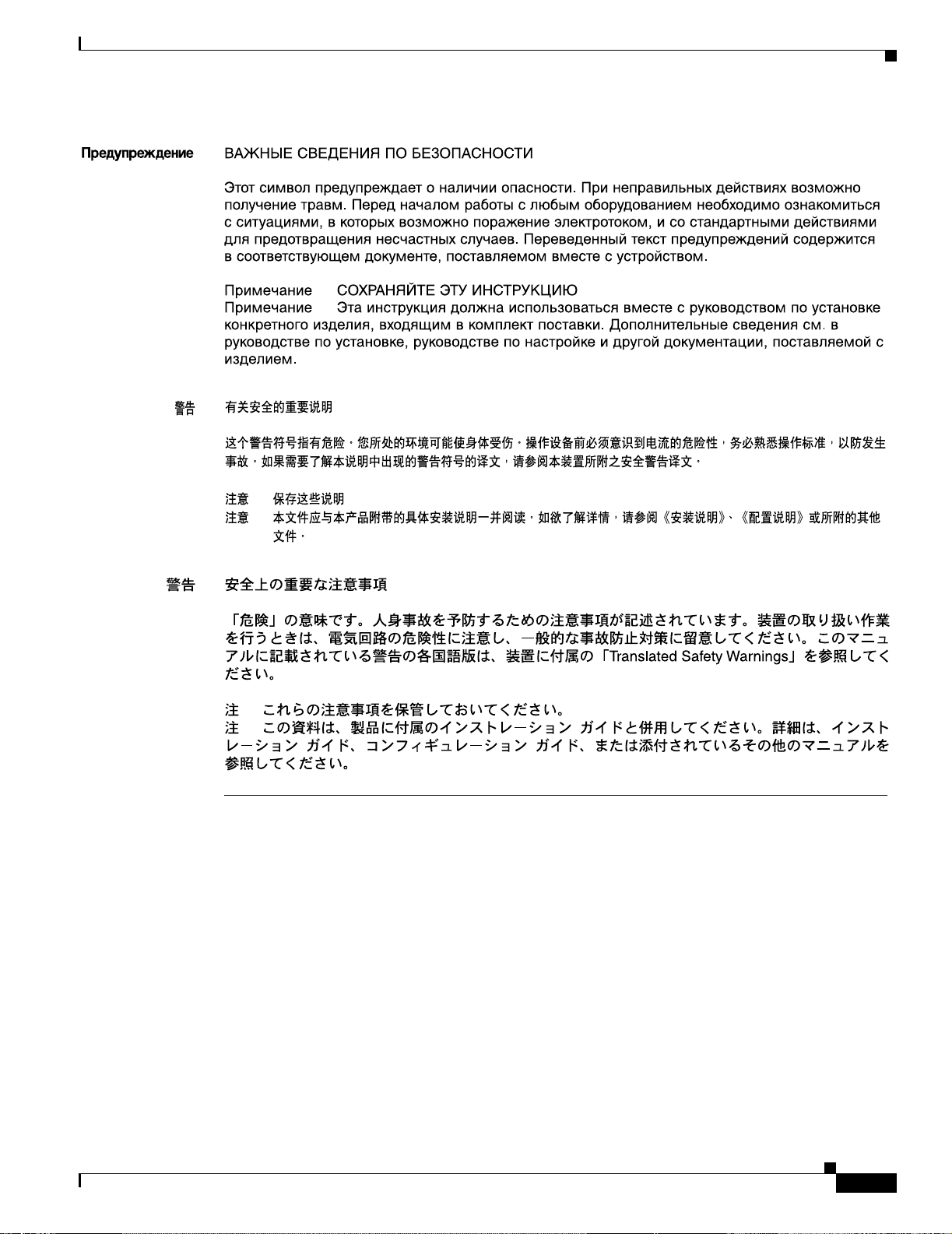
Figure 1-1 Cisco 7401ASR Router—Front View
ENABLED
RX CELLS
RX CARRIER
RX ALARM
TX
RX
E
N
H
A
N
C
E
D
A
T
M
4
5
7
8
10
11
13
1
2
3
6
9
12
57606
1 Port adapter slot (with installed port adapter) 8 Conso le port
2 Port adapter latch 9 Alarm port
3 GBIC port 0 10 Ground for ESD wrist strap banana j ac k
4 FE port 0 11 Power switch
5 FE port 1 12 CompactFlash Disk slot
6 GBIC port 1 13 Power connector
7 Auxiliary port
The Cisco 7401ASR ro ute r s uppo rts:
• Two native Ethernet interfaces—Each interface has two physical ports, a Gigabit Ethernet
(1000-Mbps) port t h at uses a G igab it In terface C onverter (GBIC) and a Fast E ther ne t/Et herne t
(10/100-Mbps) port with an RJ-45 connector. Any two of the four ports are available at any one time.
• Both 25-MHz an d 5 0-MH z port ada pt er ope rat ion.
1-2
• A 64- or 128-MB CompactFlash Disk.
• A single power supply that is available in four options : AC, single –24V DC, single –48V DC, and
dual –48V DC.
Cisco 7401ASR Installation and Configuration Guide
OL-5419-01 B0
Page 23
Chapter 1 Overview and Par ts Ins ta ll at ion
LEDs
LED information is in Figure 1-2 and the table bel ow Figure 1-2.
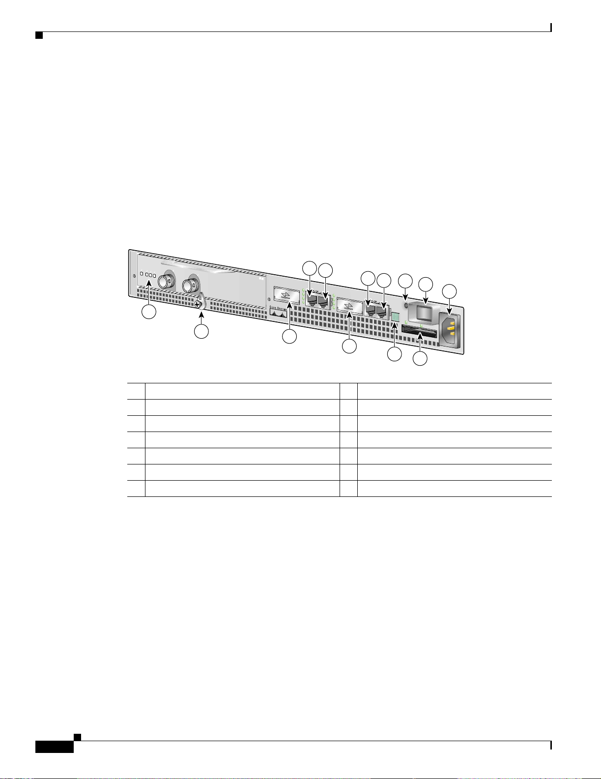
Figure 1-2 LEDs on the Cisco 7401ASR Router
1
2
3
4
Hardware Ov erview
5
6
9
10
57605
7
8
No. LED Label LED Color
In the Power Up
state, the LED is
LED flashes when there is
traffic
1 GBIC 0 ENABLE GBIC 0 ENABLE Green On No, remains constantly on
2 LI NK GBIC LINK 0 Green — Yes
3 FE 0 LINK FE 0 LINK Green — Yes
4 100 Mbps FE 0 Gre en On No, remains constantly on
5 GBIC 1 ENABLE GBIC 1 ENABLE Green — No, remains constantly on
6 LI NK GBIC LINK 1 Green On Yes
7 FE 1 LINK FE 1 LINK Green — Yes
8 100 Mbps FE 1 Gre en On No, remains constantly on
9 STATUS System Status Green On No, remains constantly on
10 COMPACT
FLASH
CompactFlash
Disk
Green On, if the
CompactFlash
Disk is inserted
No, remains constantly on
if the CompactFlash Disk
is inserted and f unc tioni n g
and functioning
OL-5419-01 B0
Cisco 7401ASR Installation and Configuration Guide
1-3
Page 24
Hardware Overv iew
Rear View
Chapter 1 Overview an d Parts Installation
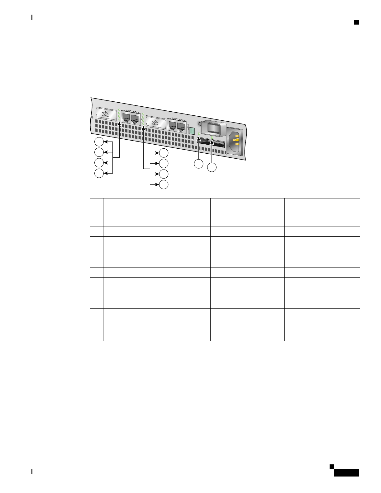
Figure 1-3 Cisco 7401ASR Router—Rear View
System Board
1
50530
2
1 Fan vent 2 Grounding connector
The rear of the Cisco 7401 ASR route r has five fan airflow vents and the chassis groundi ng connec tor
that provides a chassis gro und conn ec tion for ES D e quipm ent or a two-hole gro und ing l ug. (Se e
Figure 1-3.)
Five internal fans draw cooling air into the chassis and across internal components to maintain an
acceptable operating temperature. (See Figure 1-3.) The five fans are located at the rear of the chassis.
Internally, the system board contains the following components:
• SDRAM memory that is available in thre e option s: 128, 256, or 512 MB DIMM
• Processors
–
Reduced instruction set computing (RISC) RM7000 microprocessor that operates at an internal
clock speed of 375 MHz. The RM7 000 processo r maint ains and executes the system
management function s for the Cisco 7401ASR router. The processor also performs some
memory and environmental monitori ng funct ions.
1-4
–
The Parallel eXpress Forwarding (PX F) processo r enab les para llel IP mul tipacket p rocessing
functions, working with the Route Processo r to prov ide acceler ated pack et switching , as well as
accelerated IP Layer 3 feature processing.
• System controller
The system contr oller pro vides hardw are logic to inte rconnect the pr ocessors , SDRAM, and th e PCI
buses. The Cisco 7401A SR ro ut er ha s one s yst em c on troll er t hat p rovid es pr oce ssor a cce ss to the
two PCI buses. The system controller also allows the port adapter access to SDRAM.
• Cache memory
The processor has three levels of cache: primary and secondary cache that are internal to the
microprocessor wit h sec ond ary u ni fied cac he f or dat a an d inst ructi on, a nd ter tiar y, 2-MB external
cache.
• Two environmental sensors for m oni tor ing the in te rnal t emp er atur e of the cha ssis
• Boot ROM for storing sufficient code for booting the Cisco IOS software
Cisco 7401ASR Installation and Configuration Guide
OL-5419-01 B0
Page 25

Chapter 1 Overview and Par ts Ins ta ll at ion
System Manageme nt F unc tions
The Cisco 7401ASR process or perform s the following syste m manageme nt functi ons:
• Sending and receiving routing pr otocol upda tes
• Managing tables, caches, and buffers
• Monitoring interface and environmental status
• Providing Simple Network Managemen t Protocol (SNMP) manage ment throu gh the conso le and
Telnet interface
• Accounting for and switching of data traffic
• Booting and reloading images
• Managing the port adapter (including recognition and initialization during online insertion and
removal)
Note For a chassis footprint, addi tional dime nsio ns, and clear ance requi remen ts for the Ci sco 7401ASR
router, see the “Preparin g to In stall th e Cisco 7 401ASR Ro uter ” section on page 2-1 in Chapter 2 ,
“Rack-Mounting, Ta bletop Installation, and Cabling.”
Checking the Shipping Container Contents
The Cisco 7401ASR router supports multiprotocol, multimedia routing and bridging with a wide variety
of protocols and p ort ad apt ers .
Checking the Shipping Containe r Contents
Use the Cisco 7401ASR Components List to check the contents of the Cisco 7401ASR router shipping
container. Do not discard the shipping container. You need the container if you move or ship the Cisco
7401ASR router in the fu ture.
Table 1-1 Cisco 7401ASR Components List
Component Descri pt i on Received
Chassis Cisco 7401ASR chassis configured with an AC or DC power supply, a port adapter
filler plate, and a CompactFlash Disk
Accessories:
• Rack-mount and
cable-management
kit
• Power cables
• Documentati on
The following accessories might arrive in separate shipping containers:
Two rack-mount brackets, one cable -manage ment brac ket,
four 12-24 x 0.5-in. screws to secure the rack-mount brackets to the chassis, four 8-18
x .37-in. screws to secure the rack-mount brackets to a 19-inch rack, four 8 x .375-in.
screws to secure the rack-mount brackets to a 21–23-inch rack, and one M4 x 20-mm
screw to attach the cable-management bracket to the rack-mount bracket
An AC power cable, if an AC power supply was ordered
If ordered, route r hardware an d so ft ware do cu ment ati on se t a nd the Cisc o
Documentation CD-ROM package
1
Optional Equipment Examples: Network interface cables, transceivers, special connectors
1. Titles and quantities of documents will vary. You must order the type and quantity of documentation sets when you order the hardware.
Cisco 7401ASR Installation and Configuration Guide
OL-5419-01 B0
1-5
Page 26

Installation Checklist
Note We no longer ship the entire router documentation set automatically with each system. You must
specifically order the documentation as part of the sales order. If you ordered documentation and did not
receive it, we will ship the documents to you within 24 hours. To order documents, contact a customer
service representative.
Installation Checklist
This section assumes you will be installing th e CompactFlash Disk, Gigabit I nterface Con v erter (GBIC),
and port adapter or servi ce adapte r befor e powering on the rou ter, or before install ing it in a rack and
powering it on. For complete site requirement information, see Chapter 2, “Rack-Mounting, Tabletop
Installation, and Cabling,” the “Site Requirement Guidelines” section on page 2-4.
To assist you with yo ur insta llat ion an d to pr ovide a hi storic al re co rd of w hat was d one by w ho m,
photocopy the Cisco 7401ASR Router Installati on Checklist, Table 1-2 on page 1-6. Indicate when each
procedure or verification is comp leted . When the ch eckli st is compl eted, place it in your si te log along
with the other records for your new router.
Chapter 1 Overview an d Parts Installation
Table 1-2 Cisco 7401ASR Router Installation Checklist
Task
Date router received
Router and all accessories unpacked
Types and numbe rs of i nte rface s verified
Safety recommendations and guidelines reviewed
Installation Checklist copied
Site log established and background information entered
Site power voltages verified
Site environmental specifications verified
Required passwords, IP ad dresses, device nam es, and so on , available
Required tools available
Network connection eq uipm ent available
Router mounted in rack (optional)
Cable-manageme nt bracket inst alled (opti onal but recomm ended)
AC power cable(s) connected to AC source(s) and router
DC power cable(s) c on nect ed t o DC sour ce (s) a nd ro ute r
Network interface cables and devices connected
ASCII terminal attached to console port
Console port set for 9600 bau d, 8 data bits , no parity, and 2 stop bits (9600 8N2)
System power turned on
System boot comple te (STATUS LED is on )
Verified
By Date
1-6
Cisco 7401ASR Installation and Configuration Guide
OL-5419-01 B0
Page 27
Chapter 1 Overview and Par ts Ins ta ll at ion
Installing the CompactFlash Disk, GBIC, and Port Adapter
Table 1-2 Cisco 7401ASR Router Installation Checklist
Verified
Task
By Date
I/O ports and port adapter are operational (see Figure 1-2 on page 1-3 for specific LED information)
Correct hardware configuration displayed after system banner appears
Installing the CompactFlash Disk, GBIC, and Port Adapter
You may have ordered a CompactFlash Disk, Gigabit Interface Converter (GBIC), and one of a variety
of port adapters or service adapter with your Cisco 74 01ASR router. You must install the Com pactFlash
Disk, GBIC, and port adapter service adapter. Use the installation instructions in the following sections
to install or remove one of these optional parts:
• Installing and R emoving the C omp actF lash Di sk, pa ge 1 -7
• Installing and R em oving t he G igab it In terfa ce C onverter, page 1-8
• Installing and R em oving a Por t Ad apt er or Ser vic e A dap ter, page 1-1 0
Installing and Removing the CompactFlash Disk
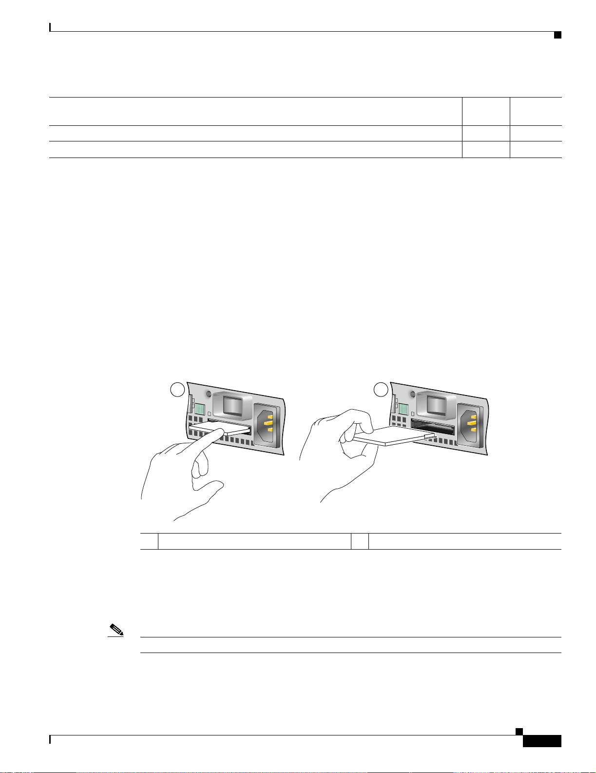
Figure 1-4 Installing and Removing the CompactFlash Disk
1 2
1 CompactFlash Disk insertion 2 CompactFlash Disk removal
Insert the CompactFlash Disk in the CompactFlash Disk slot (1) with the label with the v endor name and
memory size facing up. It protrudes when completely seated. To remove the CompactFlash Disk, grasp
it and pull it from the slot (2).
The CompactFlash Disk is keyed to prevent it being inserted incorrectly.
57604
OL-5419-01 B0
Note Only the CompactFl ash Disk is su ppo rte d in a Cisco 740 1A SR rout er.
Cisco 7401ASR Installation and Configuration Guide
1-7
Page 28
Installing the CompactFl ash Disk, GBIC, and Port Adapter
Information about CompactFlashDisks:
• The larger the Comp actFl ash Disk size, the longe r the sys tem boot time .
• The CompactFlash Disk supports online insertion and removal (OIR).
• Use the CompactFlash Disk t o store your confi gurat ion fi les and Ci sco IOS software image .
For complete information about using a Co mpactFlash Disk, see Appe ndix C, “Using the CompactFlash
Disk.”
For further installation proc edures i ncluding ra ck-moun ting or ge neral workbe nch instal latio n, see
Chapter 2, “Rack-Mounting, Tabletop Installation, and Cabling.”
Installing and Removing the Gigabit Interface Converter
For ease of installation, insert the Gigabit Ethernet Gigabit Interface Converter (GBIC) in the router
while it is powered down and before placing it in a rack. For complete GBIC installation instructions,
see the “Attachi ng the GBIC Inter face Cable s” section on page 2-17 and see the “Gigabit Ethernet GBIC
Configurations and Port and Cabling Specifications” section on page A-4.
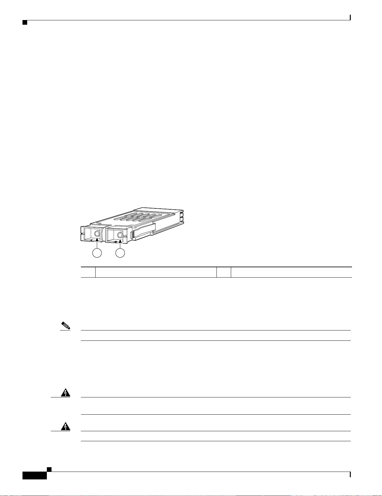
Figure 1-5 Gigabit Interface Converter—GBIC
Chapter 1 Overview an d Parts Installation
57018
1 2
1 Receive 2 Transmit
The Gigabit Ethernet Gigabit Interface Converter (GBIC) port is a 1000-Mbps optical interface in the
form of an SC-type duplex port tha t support s IEEE 802 .3z inter faces compl iant wit h the 1000BASEX
standard. Gigabit Interface Converter models WS-5484 or GBIC-SX, WS-G5486 or GBIC-LX/LH, and
WS-G5487 or GBIC-Z X a re su ppo rted in t he Ci sco 7401ASR router.
Note The GBIC must be installed before you connect the cables to it.
• You can install and remove GBICs with power on to the system.
• Disconnect all c abl es be fo re r em oving or in s tall ing a GBIC. We strongly recomm end th at you do
not install or remove the GBIC with optical fiber cables attached to it.
• GBICs are keyed to prevent incorrect insertion.
Warning
Because invisible laser radiation may be emitted from the aperture of the port when no fiber cable is
connected, avoid exposure to laser radiation and do not stare into open apertures.
1-8
Warning
Cisco 7401ASR Installation and Configuration Guide
Class 1 laser product.
OL-5419-01 B0
Page 29
Chapter 1 Overview and Par ts Ins ta ll at ion
Installing the CompactFlash Disk, GBIC, and Port Adapter
Warning
Class 1 LED product.
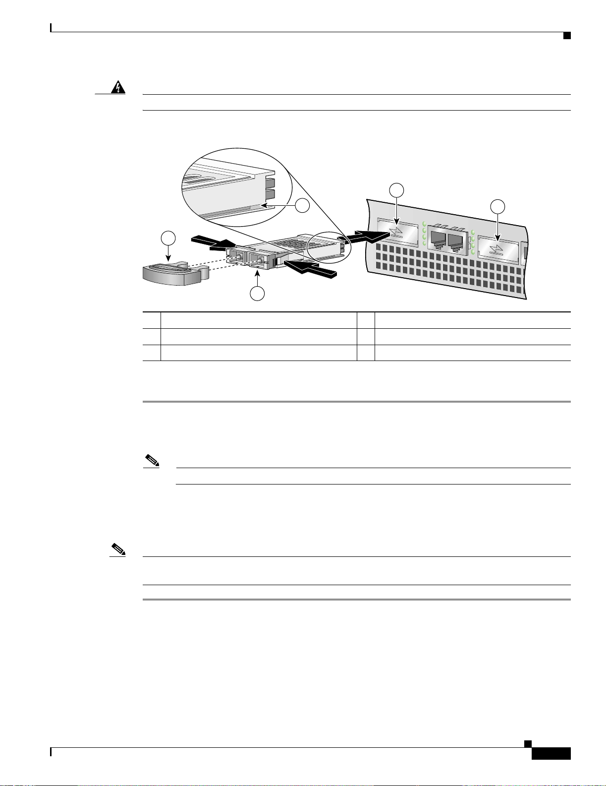
Figure 1-6 Inserting a GBIC into the Cisco 7401ASR Gigabit Ethernet Slot 0
3
2
5
1
1 Gigabit Interface Converter (GBIC) 4 GBIC por t 1
2 Alignment groove 5 Plug
3 GBIC port 0
Use the following procedure to install a GBIC:
4
57603
Step 1 Attach an ESD-preventive wrist strap between you and an unpainted chassis surface.
Step 2 Locate the label on the GBIC and turn the GBIC so the label is on top and the alignment groove is
down.
Note The GBIC is keyed so that it cannot be insert ed inco rrect ly.
Step 3 Insert the GBIC into GBIC slot 0 or 1. The tabs on either side of the GBIC snap into place when you
have completely and properly inserted the GBIC.
Step 4 Repeat Step 2 and Step 3 if you ar e insert ing a seco nd GBIC.
Note Do not remove the plug from the GBIC optica l bor es until you ar e read y to in stall the n etw o r k interf a ce
optical fiber cable. Save the plug for f ut ure use.
This completes the GBIC installation procedure.
OL-5419-01 B0
Cisco 7401ASR Installation and Configuration Guide
1-9
Page 30
Chapter 1 Overview an d Parts Installation
Installing the CompactFl ash Disk, GBIC, and Port Adapter
Installing and Removing a Port Adapter or Service Adapter
The information in this sect ion also applies t o service ada pters. Fo r information a bout conf iguring a port
adapter, see the p o rt ad ap te r do cu ment ati on a t :
http://www.cisco.com/univercd/cc/td/doc/product/core/7200vx/portadpt/index.htm.
Warning
When performing the following procedures, wear a grounding wrist strap to avoid ESD damage to the
card. Some platforms have an ESD connector for attaching the wrist strap. Do not directly touch the
midplane or backplane with your hand or any metal tool, or you could shock yourself.
Before removing any port adapter, gracefully shut down the interface so that thre is no traffic running
through the port ad apter w hen it is removed. Removing a po rt adap ter whe n traffic is flowing through
the ports can cause system disruption .
The Cisco 7401ASR ro ut er s uppo rts OI R o f th e port ada pte r. However, if you choose to power off the
router to remove or install a port adapter, turn the power switch to the off position and then remove the
power cable. After you have replaced the port adapter or inserted afiller panel, replace the power cable
and then turn the power switch to the on position.
Note After powering off the router, wait at l east 3 0 se cond s be fore p owering i t on again.
Follow these steps for inserting and securing a por t adapte r:
Step 1 Attach an ESD wrist strap between you and an unpainted chassis surface. For wrist straps with a banana
jack, insert the bana na ja ck i n it s gr oundi ng ho le lo ca ted on th e front o f th e chas sis, n ear the STATUS
LED and power switch.
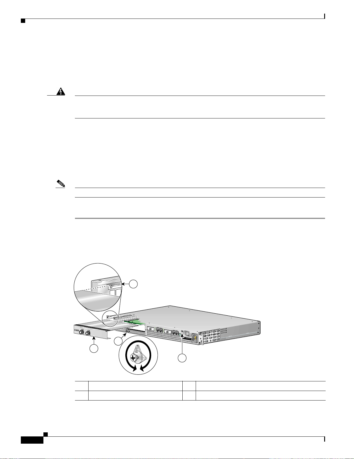
Figure 1-7 Installing a Port Adapter or Service Adapter
1-10
3
D
R
E
S
IE
L
L
M
R
L
B
R
R
E
A
A
A
L
C
N
C
X
X
E
A
X
T
R
X
R
R
X
R
ENHANCED ATM
1
2
1 Port adapter latch 3 Port adapter slot guide
2 Port adapter 4 Ground for ESD wrist strap b anan a j ack
Cisco 7401ASR Installation and Configuration Guide
57579
4
OL-5419-01 B0
Page 31

Chapter 1 Overview and Par ts Ins ta ll at ion
Replacing the SDRAM DIMM
Step 2 Using a Phillips screwdriver, loosen t he scr ew of the port adapter la tch , an d ro tate the p o rt adap ter la tch
until it clears the faceplate of the port adapter. The latch can rotate 360
Step 3 Pull the port adapter about halfway out of the port adapter slot. (If you remove a port adapter filler plate,
o
.
keep the blank por t a dap ter f or use i n t he rout er if y ou shou ld ever remove the p or t ad apt er. The port
adapter slot must always be filled .)
Step 4 With the port ad ap ter ha lfwa y out of t he sl ot, disc on nect al l ca bl es fr om the po rt adapt er. After
disconnecting the cable s, pull the port adapte r from the c hassis slot.
Step 5 Loca te the port adapter sl ot guide s inside th e Cisco 7401A SR router. They are near the top, and are
recessed about one-h alf inch.
Caution The port adapter must slide into the slot guides under the chassis lid. Do not allow the port adapter
components to come in contact with the system board or the port adapter could be damaged.
Note If it is easier to attach the port adapter cables with the port adapter inserted halfway, attach the cables
before seating t he po rt ad ap ter and sec uri ng the po rt a dapt er lat ch.
Step 6 Locate the port adapter slot guides. Carefully slide the por t ad apter in to the por t ad apter slo t an d seat it .
When installed, the port ad apter i nput/o utput pane l should be flu sh with the fac e of the route r.
Step 7 Rotate the port adapter latch to the upright locked position and use a Phillips screwdriver to tighten the
latch screw. Loosen the latch screw, if needed, to be able to rotate the latch over the port adapter. Then
tighten the latch screw.
This completes the port adapter installation procedure.
Caution To ensure the proper flow of cooling air across the internal components, make sure a port adapter filler
panel is installed in the unoccupied port adapter slot.
For further installatio n procedure s, see Chapter 2, “Rack-Mounting, Tabletop Installation, and Cabling.”
Replacing the SDRAM DIMM
The information in this section provides instructions for replacing the SDRAM DIMM and is included
for future use. The memory c onfiguration you ordered is installed in the Cisco 7401ASR rout er.
Warning
Warning
Only trained and qualified personnel should be allowed to install, replace, or service this equipment.
Before working on a chassis or working near power supplies, unplug the power cord on AC units;
disconnect the power at the circuit breaker on DC units.
OL-5419-01 B0
Cisco 7401ASR Installation and Configuration Guide
1-11
Page 32

Replacing the SDRAM DIMM
Chapter 1 Overview an d Parts Installation
Warning
When performing the following procedures, wear a grounding wrist strap to avoid ESD damage to the
card. Some platforms have an ESD connector for attaching the wrist strap. Do not directly touch the
system board with your hand or any metal tool, or you could shock yourself.
To replace or upgrade the SDRAM DIMM, follow these instructions:
Removing the Cover
The Cisco 7401ASR router cover fits tightly on the chassis. Follow these instructions to remove the
cover:
Step 1 Power off the router by turning the power switch to the off position.
Note After powering off the router, wait at least 3 0 sec onds be f ore p owering it on a gain.
Step 2 Remove any cables from the Cisco 7401ASR router, including the power cables. For AC power supplies,
unplug the AC po w er cord fro m the po wer outlet. F or DC po we r supplies, to ensure tha t all po wer is of f,
locate the circuit breaker on the panel board that services the DC circuit, switch the circuit breaker to
the off position, and tape the switch handle of the circuit breaker in the off position.
Figure 1-8 Removing the Screws and Releasing the Cover
1
2
D
E
L
B
A
N
E
TX
RX CELLS
RX CARRIER
RX ALARM
RX
E
N
H
A
N
C
E
D
A
T
M
1 Cover s c r ew s 2 Cover removal slot and flatblade sc rewdriver
Step 3
Step 4 Remove the four screws holding the cover to the chassis.
Remove the Cisco 7401A SR ro ut er from t he ra ck , if it is ra ck-m oun ted.
Note If needed, use a Phillips recess flat-head screw, M3.5 x 6-mm long, type B thread, steel with
black zinc coating, as a replacement.
Step 5 Inser t a fla t-bl ade screwdr iver in each o f th e side cover rem oval slots.
Step 6 Push the screwdriver blade against the cover latches to release the cover, as shown in Figure 1-8. The
cover moves forward about one-quarter inch .
66448
1-12
Cisco 7401ASR Installation and Configuration Guide
OL-5419-01 B0
Page 33

Chapter 1 Overview and Par ts Ins ta ll at ion
Figure 1-9 Removing the Cover
R
S
IE
L
M
R
L
R
R
E
ABLED
A
A
L
C
C
X
X
EN
A
X
T
R
X
R
R
X
R
E
N
H
A
N
C
E
D
A
T
M
Step 7 Slide the cover forward about one-half inch and then lift it from the chassis.
Removing and Installing the SDRAM DIMM
Replacing the SDRAM DIMM
66449
Follow these instructions to remove and replace the SDRAM DIMM:
Figure 1-10 Removing and Replacing the DIMM
3
2
1
66284
OL-5419-01 B0
1 Spring latch on DIMM socket 3 Notch
2 DIMM
Step 1 Attac h an ESD -preventative wrist s trap bet wee n you a nd an u npa int ed r oute r surface.
Step 2 Locate the DIMM.
Cisco 7401ASR Installation and Configuration Guide
1-13
Page 34

Replacing the SDRAM DIMM
Step 3 Press both spring latches outward to release the DIMM. See Figure 1-10.
Step 4 Gently pull the DIMM free from the DIMM socket, taking care not to touch the pins that insert into the
socket. Place the DIMM in an anti-static bag.
Caution Forcing the DIMM into the socket can damage the DIMM. Use the notches on the DIMM to align the
DIMM with the DIMM socket before inserting it.
Step 5 Locate the notches and align the DIMM with the DIMM socket.
Step 6 Gently i nsert the new DIM M, taki ng ca re no t to da mage the p ins o n th e ed ge o f th e DIM M.
Step 7 Press the spring latches to lock the DIMM in place.
Replacing the Cover
Step 1 Repl ace the cover; lower it onto th e chas sis an d push the cover toward th e rear of th e chass is to lock it
in place.
Chapter 1 Overview an d Parts Installation
Step 2 Replac e and tighte n the four cover screws.
Replace the Cisco 7401ASR router in the rack. See Chapter 2, “Rack-Mounting, Tabletop Installation,
and Cabling” for instructi ons.
For memory specifications and configurations, see Appendix A, “Specifications” the “Memory
Specifications and Configurations” section on page A-3.
1-14
Cisco 7401ASR Installation and Configuration Guide
OL-5419-01 B0
Page 35

CHAPTER
2
Rack-Mounting, Tabletop Installation, and Cabling
This chapter explains how to install a Cisco 7401ASR router in a rack in a general tabletop or workbench
installation, how to a tt ach cabl es , a nd how to power on t he r oute r.
This chapter contains the following sections:
• Preparing to Install t he C isco 74 01ASR Rou ter, page 2-1
• Installing the Router, page 2-5
• Attaching a Chassis Ground Conn ection, page 2-11
• Connecting Port Adapter Cables, page 2-13
• Connecting I/O Cables, page 2-14
• Attaching the Alarm Port Cable, pag e 2-22
• Using the Cable-Manag ement Br acket, page 2-22
• Connecting Power, page 2-23
The Cisco 7401 ASR ro ute r ope ra tes as e ither a ta ble top o r a ra ck-m oun ted un it. A r ack -mo unt ki t i s
standard equipmen t include d with the Cisco 740 1ASR route r when it is shipp ed from the factory. The
kit provides the hardware needed to mount the router in a standard 19-inch equipment rack or a two post
rack or a 21–23-inch equi p ment r ack.
If you are not rack-mount ing your Cisco 7401ASR router, place it on a sturdy tabletop or pla tform.
Preparing to Install the Cisco 7401ASR Router
Before installing your Cisco 7401ASR router, you should consider the power and cabling requirements
that must be in place at your installation site, the equipment you need to install the router, and the
environmental conditions your installation site must meet to maintain normal operation. This section
guides you through the proce ss of prep aring for your router install ation and t he installa tion in a rack .
This section contains the following topics:
• Tools and Parts Required, page 2-2
• Electrical Equipment Guidelines, page 2-3
• Preventing Electrostatic Discharge Damage, page 2-4
• Site Requirement Guidelines, page 2-4
OL-5419-01 B0
Cisco 7401ASR Installation and Configuration Guide
2-1
Page 36

Preparing to Install the Cisco 7401ASR Router
Figure 2-1 Dimensions of Cisco 7401ASR Router
Chapter 2 Rack-Mounting, Tabletop Installation, and Cabling
2
1
1 12.875 in. (32.7cm) 3 11.8 in. (30 cm)
2 17.3 in. (43.9 cm)
Table 2-1 provides dimensions and weight information.
Table 2-1 Cisco 7401ASR Dimensions and Weight
Cisco 7401ASR
Dimensions (H x W x D) 1.72 in. x 17.3 i n. x 11 .8 0 in . ( 4. 37 cm x 4 3.9 c m x 30 cm )
Weight Chassis fully configured with a port adapte r ~ 10.5 lb (4. 76 kg)
Tools and Parts Required
3
50537
2-2
Yo ur Cisco 7401 ASR chassis is full y assemble d at the factory; no asse mbly is requ ired. H owever, you
need the following tools and equipment to install the chassis and the rack-mount and cable-management
kit:
• Number 2 Phillips screwdriver
• A 3/16-inch fla t-bla de sc rewdriver
• Tape measure (optional)
• Level (optional)
The rack-mount and ca ble-m anagem ent kit inc ludes t he following par ts:
• Two rack-mount brackets for mounting the chassis in the rack
• One cable-management bracket
• Four 12-24 x 0.5-in. screws to secure the ra ck-m ount brac kets to the cha ssis
• Four 8-18 x .37-in. screws to se cu re t he r ack- mo unt bra ckets to a 19- inc h rac k
• Four 8 x .375-in. screws to secure the ra ck-moun t brac kets to a 21–23-inch rack
• One M4 x 20-mm screw to attach the cable-management bracket to the rack-mount bracket
Cisco 7401ASR Installation and Configuration Guide
OL-5419-01 B0
Page 37

Chapter 2 Rack-Mounting , Tabletop Installation, and Cabling
• Grounding lug and wire s:
–
A grounding lug w ith t wo num be r-10 screw holes with a 0.63- inc h (16. 00 2-m m) spa ci ng
between them
–
A wire receptacle large enough to accept a 6-AWG multistrand, copper wire
–
Two Phillips machine screws with locking washers—M5 (metr ic) , 0.0 31-i nc h ( .08 -mm) pi tc h,
0.315-inch (8-mm) leng th
–
A crimping tool t o fit t he gr ou nding l ug w ire r ecep tacl e
–
One grounding wi re—6-AWG, 0.162-inch (4.115-mm) dia meter, with app rox ima tel y
0.108-inch (2.743-m m) insula tion, for a t otal wir e diamet er of approx imatel y 0.27 in ches
(6.858 mm). The wire len gth depe nds on your rou ter locati on and sit e environment.
In addition, you might nee d the foll owing external eq uipmen t:
• Data service unit (DSU) to connect each serial port to an external network
• T1 channel service unit/data service unit (CSU/DSU) that converts the High-Level Data Link
Control (HDLC) synchronous serial data stream into a T1 data stream with the correct fram ing and
ones density to connec t a serial port to a T1 network. (Some telephone systems require a mini mum
number of 1 bits per time un it in a data st rea m, ca lled ones density.) Several T1 CSU/DSU device s
are available as additional equipment, and most provide a V .35, EIA/TIA-449, or EIA-530 electrical
interface.
Preparing to Install the Cisco 7401ASR Router
• Ethernet transceiver
• Token Ring multistation access unit (MSAU)
• ESD-preventative wrist strap
• Power cord
• Appropriate cables to connect the router to the console and auxiliary ports
Electrical Equipment Guidelines
The port adapter is designe d to be removed and re place d while th e system is op erating without
presenting an el ectri cal ha zard or dama ge to th e syste m.
Follow these basic guidelines when working with any electrical equipment:
• Before beginning any procedures requiring access to the chassis interior, locate the emergency
power-off switch for the room i n whi ch y ou ar e worki ng.
• Disconnect all power and external cables before moving a chassis.
• Do not work alone when potentially hazardous conditions exist.
• Never assume that power has been d isco nnecte d from a c ircui t; always check.
• Do not perform any action that creates a potential hazard or makes the equipment unsafe.
• Carefully examine your work are a f or possib le ha zard s suc h as m oi st fl oors, u ngr ounde d p ower
extension cables, and mis sing saf ety groun ds.
OL-5419-01 B0
Cisco 7401ASR Installation and Configuration Guide
2-3
Page 38

Safety Guidelines
Safety Guidelines
Following are safety guidelines that you should follow when working with any equipment that connects
to electrical power, or which might be sensit ive to electro stati c disc harge ( ESD) dama ge.
Preventing Electrostatic Discharge Damage
Electrostatic discharge (ESD) damage, which occurs when electronic cards or components are
improperly handled, can result in complete o r intermitt ent system f ail ures. Eac h port adap ter con sists of
a printed circuit board that is fixed in a metal carrier. Electromagnetic interference (EMI) shielding,
connectors, and a handl e are integral c omponent s of the carrie r. Although the carrier helps prot ect the
boards, use an antistat ic str ap whenever handling the po rt ad apter. Handle the carriers by the handle and
the carrier edg es on ly; never touch t he boa rd s or c on nect or p in s.
Electrostatic Discharge Prevention
Electrostatic discharge (ESD) damage, which can occur when electronic cards or components are
improperly handled, results in complete or intermittent failures.
Chapter 2 Rack-Mounting, Tabletop Installation, and Cabling
Use the following guidelines for preventing ESD damage:
• Always use an ESD wrist or ankle strap and ensure that it makes good skin contact; connect the
equipment end of the strap to an un finished cha ssis surface.
• Avoid contact betwe en t h e pri nte d cir cuit boa rd s and c lothi ng. T he wr ist stra p o nly pro tec ts
components from ESD voltages on the body ; ESD voltages on clo thing ca n still cause damage.
Caution For safety, periodically check the resistance value of the antistatic strap. The measurement should be
between 1 and 10 megaohms ( Mo hms).
Site Requirement Guidelines
Warning
Before you install, operate, or service the system, read the Site Preparation and Safety Guide. This
guide contains important safety information you should know before working with the system.
The environmental moni toring f unc tiona lity i n th e Cisc o 7401 ASR r oute r prote ct s the syst em and
components from potential damage from overvoltage and overtemperature conditions. To ensure normal
operation and avoid unnecessary maintenance, plan your site configuration and prepare your site before
installation. After installation, make sure the site maintains an ambient temperature of 32°F through
104°F (0°C throu gh 40°C ), a nd keep t h e ar ea ar ound th e cha ssis as free f ro m d ust a s is prac ti cal .
2-4
Planning a proper location for the Cisco 7401ASR router and the layout of your equipment rack or wiring
closet is essential for successful system operation. Equipment placed too close together or inadequately
ventilated can cause system overtemperature conditions. In addition, chassis panels made inaccessible
by poor equipment placement can make system maintenance difficult. Following are precautions that can
help avoid problems during i nstall atio n and on goin g o pe ratio n.
Cisco 7401ASR Installation and Configuration Guide
OL-5419-01 B0
Page 39

Chapter 2 Rack-Mounting , Tabletop Installation, and Cabling
Figure 2-2 Airflow Through the Chassis
D
R
E
E
S
I
L
L
M
R
L
B
R
R
E
A
A
A
C
L
N
C
A
X
X
E
X
T
R
X
R
R
X
R
E
N
H
A
N
C
ED
A
T
M
When you plan the location and layout of your eq uipmen t rack or wi ring cl oset, you need to con sider
how air flows through your router. The Cisco 7401ASR router draws cooling air in throug h the int ake
vents on the front of the chassis a nd moves the air across the i nterna l compon ents and out the exhaust
vents on the rear of the chassis. Figu re 2-2 shows airflow through the router.
Temperature sensors on the system board monitor the internal air temperature and send warning
messages when the internal a ir tempe rature ap proache s a specified threshold. If the inte rnal temperatu re
exceeds the specified threshold, the system environmental monitor shuts down all internal power to
prevent equipment damage from excessive heat. (See the “Environmental Monitoring and Re portin g
Functions” section on pa ge 3- 4 for temperature threshold information.)
Installing the Router
50533
Installing the Router
This section expla ins how to inst all a Cisco 7 401 ASR ro uter in a gene ra l ta ble top or work benc h
installation and in a rack, and how to attach I/O, port adapter, and power cables. This section contains
the following topics:
• General Tabletop or Workbench Installa tion, page 2-5
• Rack-Mounting a Cisco 74 01A SR Rou t er, page 2-6
• Attaching the Chassis Rack -Mount and Ca ble-Ma nagement Brackets, pa ge 2-7
• Installing the Chassis in the Rack, page 2-9
General Tabletop or Workbench Installation
The router should alr eady be in the area where you will inst all it, and yo ur install atio n locatio n should
already be determined. If not, see the “Preparing to Install the Cisco 7401ASR Route r” section on
page 2-1, the “Site Requirement Guidelines” section on pa ge 2-4, and the “Site Preparation and Safety”
section of the Cisco 74 01ASR Regulatory Comp lia nce and Sa fety I nformat ion do cu me nt.
When installing a Cisco 7401ASR router on a workbench or tabletop, ensure that the surface is clean and
in a safe location and that you have considered the following:
• The router require s at leas t 3 inc hes (7.62 cm ) of clea ranc e at the in let an d exhaust vents (the fron t
and rear of t he rou ter ).
• The router sh ould be i nsta ll ed off th e floo r. (Dust that a ccu mula tes on the f loor is drawn in to the
interior of the router by the cooling fans. Excessive dust inside the router can cause overtemperature
conditions and co mpone nt failu re s.)
• There must be approximately 19 inches (48.3 cm) of clearance at the front and rear of the router for
installing and replacing router parts—such as the port adapter, GBIC, or CompactFlash Disk—or
accessing network ca ble s o r eq ui pment .
OL-5419-01 B0
Cisco 7401ASR Installation and Configuration Guide
2-5
Page 40

Installing the Router
Step 1 Remove any debris and dust from the tabletop or workbench, as well as the surrounding area. Also make
Step 2 On the chassis, ensure that the port adapter latch is in the locked position.
Step 3 Lift the chassis by placi ng you r hands a round t he cha ssis sides an d liftin g th e chas sis fr om unde rnea th.
Chapter 2 Rack-Mounting, Tabletop Installation, and Cabling
• A port adapter filler panel is installed if a port adapter or service adapter is not in place.
• The router will receive adequate ventilation (it is not being installed in an enclosed cabinet where
ventilation is inadequate).
• If you plan to install the cable- man ag e men t br ac k et, unpack and have handy the cable-management
bracket and one M4 x 20 -m m screw.
• An adequate chassis ground (ear th) conne ction exists for your rout er chassis.
Note W e strongly recommend that you provide a chassis ground connection. See the “Attach ing a
Chassis Ground Connec ti on” section on pag e 2-11 for instructions.
Following are the steps for installing a Cisco 7401A SR router on a workbenc h or tabletop :
sure your path be tw een t he ro ut er a nd its new loca ti on is un obst ruc ted.
To prevent injury, avoid sudden twists or moves.
Step 4 Place the rout er on the ta bletop o r wo rkben ch .
Step 5 Ensure that there is at least 3 inches (7.62 cm) of clearance at the inlet and exhaust vents of the router
and no exhaust air from other equipment will be drawn into the chassis. Also, ensure that there is
approximately 19 inches (48.3 cm) of clearance at the front and rear of the chassis.
This completes the general tabletop or workbench installation.
Rack-Mounting a Ci sco 7 40 1ASR R oute r
The chassis mounts to two rack posts with brackets that attach to either the front or the rear sides of the
chassis. The in side widt h b etwe en t he t wo po sts or m oun tin g str ips (l eft and ri ght) mu st b e at l east
17.3 inches (4 3. 9 cm) .
Some equipment rack s provide a power strip al ong the len gth of one of the mount ing str ip s. Fi gure 2-7
shows a typical four-post equipment rack with a power strip along one of the back posts. If your rack has
this feature, consider the position of the strip when planning fastener points to ensure that you will be
able to pull the port adapter, a GBIC, or CompactFlash Disk straight out of their respective slots.
The inlet and exhaust por t s for cool ing a ir a re l ocate d on the fro nt an d re ar of the ch assis, respe ctively,
so multiple routers can be stacked in a rack with little or no vertical clearance.
Before beginning the installation, determine the type of rack you are using and whether or not you want
the chassis front- or rear-mounted.
2-6
Note If you are rear-mounting the chassis and want to use the cable-management bracket, you must purchase
a second rack-mount kit. Y ou need another rack-mount bracket to attach to the front of the chassis. After
it is attached to the chassis, install the cable-management bracket to the rack-mount bracket.
Cisco 7401ASR Installation and Configuration Guide
OL-5419-01 B0
Page 41

Chapter 2 Rack-Mounting , Tabletop Installation, and Cabling
Installing the Router
Attaching the Chassis Ra ck-M ou nt and C abl e-Ma n agemen t Br ac ke ts
This section explains how to install the rac k-m ou n t and cable- m an ag em en t brackets at the front and the
rear of a Cisco 7401ASR router. Before installing the chassis in the rack, you must install a rack-mount
bracket on each side of the fr ont or rea r of the chas sis.
The parts and t oo ls r equi red f or in sta lling the rack -mo unt bra cket s and c able-m a nag eme nt br acket ar e
listed in the “To ols a nd Parts Requ ired ” section on page 2-2.
Installing Rack-Mount Brackets on the Front of the Chassis
Figure 2-3 Attaching the Rack-Mount Brackets to the Front of the Chassis
D
R
E
E
S
I
L
L
M
R
L
B
R
R
E
A
A
A
C
L
N
C
A
X
X
E
X
T
R
X
R
R
X
R
E
N
H
A
N
C
E
D
A
T
M
50531
1 2
1 Rack-mount bracke t 2 4 screws, 8-18 x .37 in., for use with a 19-inch
rack
4 screws, 8 x .375 in ., fo r use wi th a
21–23- inch rack
Determine whether you want the chassis to be flush-mounted or recessed. Figure 2- 3 shows the brackets
being attached for a front rack-mount. De pending on the bracket hole s you use, the router will protrude
or be recessed in t he r ack.
To install the rack-mount and cable-management brackets on a Cisco 7401ASR router for a front
rack-mount configuration, complete the following steps:
Step 1 Locate the threaded holes in the front sides of the chassis.
Step 2 Align the rack-mount bracket (1) to the side of the router. Depending on which set of rack-mount bracket
holes you choose to use to attach the ra ck-moun t bracke t to the router, the chassis will either be recessed
in the rack or p rot r ude f ro m t h e rack .
Step 3 Inser t and tighten two screws (2).
Step 4 Repeat Step 1 through Step 3 on the other side of t he router.
OL-5419-01 B0
This completes the steps for att aching the ra ck-m ount brackets to the Cisco 7401ASR router.
To install the cable-management bracket, go to “Attaching the Cable-Management Bracket” section on
page 2-8. If you are not installing th e cab le-m anagem ent bra cke t, go to the “Installing the Chassis in the
Rack” section on page 2-9.
Cisco 7401ASR Installation and Configuration Guide
2-7
Page 42

Installing the Router
Attaching the Cable-Management Bracket
Figure 2-4 Installing the Cable-Management Bracket
1
Chapter 2 Rack-Mounting, Tabletop Installation, and Cabling
ENABLED
RX CELLS
RX CARRIER
RX ALARM
TX
2
1 Cable-managem ent bra cket 2 M4 x 20-mm screw
Step 1 Align the ca ble-m anagem ent bracket to the rack-mou nt bracket on the left side of the Cisco 740 1ASR
router.
Step 2 Using a Phillips screwdriver and the M4 x 20-mm screw, thread and tighten the screw to the
cable-management bracket.
This completes the proce dure fo r instal ling t he c abl e-ma nage ment b racket on a Ci sco 740 1ASR r oute r
for a front rack-mount configuration. Go to the “Installing the Chassis in the Rack” section on page 2-9.
Installing Rack-Mount Brackets on the Rear of the Chassis
Figure 2-5 Attaching the Rack-Mount Brackets to the Rear of the Chassis
RX
57578
2-8
D
R
E
E
S
I
L
L
M
R
L
B
R
R
E
A
A
A
C
L
N
C
A
X
X
E
X
T
R
X
R
R
X
R
E
N
H
A
N
C
E
D
A
T
M
1 Rack-mount bracke t 2 4 screws, 8-18 x .37 in., for use with a 19-inch
To install the rack-mount and cable-management brackets on a Cisco 7401ASR router for a rear
rack-mount configuration, complete the following steps:
Step 1 Locate the threaded holes in the rear sides of the chassis.
Cisco 7401ASR Installation and Configuration Guide
2
1
rack
4 screws, 8 x .375 in ., fo r use wi th a
21–23- inch ra ck
OL-5419-01 B0
50532
Page 43

Chapter 2 Rack-Mounting , Tabletop Installation, and Cabling
Step 2 Alig n the rack -mount bra cket to the side of the rout er. Depending on which set of hole s on the
rack-mount bracket that you use, the router will either be recesse d in the rack or protrude f rom the rack.
Step 3 Insert and tighten the screws.
Step 4 Repeat Step 1 through Step 3 on the other side of t he router.
Note T o use the cable-management bracket with the Cisco 7401ASR router rear-mounted, you must purchase
a second rack-moun t kit, atta ch a rack- mount b racket to the l eft front of t he chassi s, and attac h the
cable-management brack et to it. See the “Attaching the Cable-Management Bracket” section on page 2-8
for cable-management bracket installation instructions.
This completes t he pro cedur e for in stall ing the r ack- mou nt o n a C isco 74 01ASR rou ter f or a re a r
rack-mount configurati on. Go to t he “In stalling the Chassis in the Rack” section on page 2-9.
Installing the Chassis in the Rack
Installing the Router
Caution To prevent injury, review the safety precautions in this chapter before installing the router in a rack.
After installing the brackets on the chassis, you mount the router by securing the rack-mount brackets to
two posts or mounting strips in the ra ck using th e four scr ews provided. Because the brac kets support
the weight of the entire chassis, be sure to use all four screws to fasten the two rack-mount brackets to
the rack posts. Figure 2-6 on page 2-10 and Figure 2-7 on page 2-11 show typical installations in
two-post and four-post equip me nt r acks.
We recommend that you allow at least 1 or 2 inches (2.54 or 5.08 cm) of vertical clearance between the
router and any equipment di rectly ab ove and below it.
To install the chassis in the rack, complete the following steps:
Step 1 On the chassis, ensure that the port adapter latch is in the locked position and tightened, and that the
CompactFlash Disk and any GBICs are installed.
Step 2 Make sure that your path to the rack is unobstructed. If the rack is on wheels, ensure that the brakes are
engaged or that the rack is otherwise stabilized.
Step 3 Position the chassis so that the front end is closest to you. Lift the chassis and move it to the rack. To
prevent injury, avoid sudden twists or moves.
Step 4 Slide the chassis into the rack, pushing it back until the brackets (installed at the front or rear of the
chassis) meet th e mou nt ing stri ps or po sts on bo th sid es of the equ ip ment r ack.
OL-5419-01 B0
For two-post rack installation, go to the “Two-Post Rack Installation” section on page 2-10.
For four-post rack installation, go to the “Four-Post Rack Installation” section on page 2-11.
Cisco 7401ASR Installation and Configuration Guide
2-9
Page 44

Installing the Router
Two-Post Rack Installation
Figure 2-6 Installing the Cisco 7401ASR Router in a Two-Post Rack
D
E
L
RIER
B
A
N
E
RX CELLS
X ALARM
RX CAR
R
Chapter 2 Rack-Mounting, Tabletop Installation, and Cabling
1
TX
RX
E
N
H
A
N
C
E
D
A
T
M
2
3
57572
1 Two-post or four-post rack 3 Four 12-24 x 0.5-inch screws
2 Screw hole for the cable-management
bracket
Step 1 Make sure that the port adapter latch is in the locked position and the screw is tightened.
Step 2 Make sure the rack brakes are locked or the rack is stabilized.
Step 3 Position the router so the front is closest to you and lift it car efully into the rac k. To prevent injury , a v oid
any sudden twists or moves.
Step 4 Slide the chassis into the rack, pushing it back until the brackets meet the mounting strips or posts on
both sides of the rac k.
Step 5 Keeping the brackets flush against the posts or mounting strips, align the holes in the brackets with the
holes on the rack or mounti ng strip.
Step 6 For each bra cket, inser t and tighten two 12-24 x 0.5-inc h screws to the rack .
2-10
This completes the procedure for installing the chassis in the rack. Proceed to the “Attaching a Chassis
Ground Connection” section on page 2-11 to continue the installation.
Cisco 7401ASR Installation and Configuration Guide
OL-5419-01 B0
Page 45

Chapter 2 Rack-Mounting , Tabletop Installation, and Cabling
Four-Post Rack Installation
Figure 2-7 Installing the Cisco 7401ASR Router in a Four-Post Rack
1
D
E
L
B
A
N
E
TX
RX CELLS
RX CARRIER
RX ALARM
RX
2
Attaching a Chassis Ground Connection
E
N
H
A
N
C
E
D
A
TM
3
50534
1 Four-post rack 3 Four 12-24 x 0.5-inch screws
2 Screw hole for the cable-management bracket
Step 1 Make sure that the port adapter latch is in the locked position and the screw is tightened.
Step 2 Make sure the rack brakes are locked or the rack is stabilized.
Step 3 Position the router so the front is closest to you and lift it car efully into the rac k. To prevent injury , a v oid
any sudden twists or moves.
Step 4 Slide the chassis into the rack, pushing it back until the brackets meet the mounting strips or posts on
both sides of the rac k.
Step 5 Keeping the brackets flush against the posts or mounting strips, align the holes in the brackets with the
holes on the rack or mounti ng strip.
Step 6 For each bra cket, inser t and tighten two 12-24 x 0.5-inc h screws to the rack .
This completes the procedure for installing the chassis in the rack. Proceed to the “Attaching a Chassis
Ground Connection” section on page 2-11 to continue the installation.
Attaching a Chassis Ground Connection
OL-5419-01 B0
Before you connect power or turn on power to your router, we strongly recommend that you provide an
adequate chassis gro und (earth) connect ion for the ro uter chassis. Chassis g roundin g connector s are
provided on each Cisco 7401ASR router chassis. (See Figure 2-8 on page 2-12.)
To ensure the chassis grounding connection that you provide is adequate, you will need the following
parts and tools:
Cisco 7401ASR Installation and Configuration Guide
2-11
Page 46

Attaching a Chassis Ground Connection
• One grounding lug—Must have two number-10 screw holes tha t have a 0.6 3-inc h (16.0 02- mm )
spacing between t he m, a nd a w ire r ece ptacl e l arge e noug h to a cce pt a 6-AWG multistrand, c opper
wire. This grounding lug is not available from Cisco Systems; electrical-connector vendors provide
this type of groun ding l ug.
• Two Phillips machine screws with locking washers—M5 (metr ic) , 0.0 31- inc h ( 0. 8-m m) pi tc h,
0.315-inch (8-mm) leng th. These screws are not available from Cisco Syst ems; they are available
from a commercial hardware vendor.
• One grounding wi re—6-AWG, 0.162-inch (4.115-mm) dia meter, with app rox ima tel y 0.1 08- inc h
(2.743-mm) insulation, for a total wire diameter of approximately 0.27 inches (6.858 mm). The wire
length is dependent on you r router location and si te environment. Th is wire is not available from
Cisco Systems; it is available from a commercial cable vendor.
• Number 2 Phillips screwdriver
• Crimping tool large enough to accommodate the diameter of the wire receptacle on your grounding
lug
• Wire stripper
Figure 2-8 Locating the Chassis Grounding Connector
Chapter 2 Rack-Mounting, Tabletop Installation, and Cabling
1
2
1 Fan vents 2 Ground connector
Use the following procedure to at tach the grounding lug to the ch assis groun ding conne ctor on you r
router chassis:
Step 1 Locat e t he c hassi s g roundi ng c onn ect or on y our ro uter c hassi s.
50530
2-12
Cisco 7401ASR Installation and Configuration Guide
OL-5419-01 B0
Page 47

Chapter 2 Rack-Mounting , Tabletop Installation, and Cabling
Figure 2-9 Attaching a Grounding Lug to the Chassis Grounding Connector
Connecting Port Adapter Cables
3
4
2
50536
1
1 Chassis grounding c onn ect or 3 Screws
2 Grounding lug 4 Wire
Step 2
Step 3 Insert the 6-AWG wire into the wire receptacle on the grounding lug.
Step 4 Use the crimping tool to carefully crimp the wire receptacle around the wire; this step is required to
Use the wire st r ippe r to st rip on e end of th e 6- AWG wire approximat ely 0. 75 i nc hes (19. 05 mm).
ensure a proper mech anica l connec tion.
Step 5 Inser t the two screws through the holes in the gr oundi ng lug. (See Figure 2-9.)
Step 6 Use the Number 2 Phillips screwdriver to carefully tighten the screws until the grounding lug is held
firmly to the chassis. Do not overtighten the screws.
Step 7 Connect the opposite end of the grounding wire to the appropriate grounding point at your site to ensure
an adequate chassi s g round.
This completes t he pro cedur e fo r at ta ch ing a chassi s gro und c onn ect ion. Go t o th e foll owing c ablin g
sections for informat ion on atta ching ca bles.
Connecting Port Adapter Cables
The instructions for connecting the cables for the port adapter installed in the Cisco 7401ASR router are
contained in the re spective configuration note for each port adapter. For example, if you are conn ecting
the optical fiber cables for the PA-POS-OC3 port adapter, refer to the configuration note PA-POS-OC3
Packet OC3 Port Adapter Installation and Configuration at
http://www.cisco.com/univercd/cc/td/doc/product/core/7206/port_adp/sonet_pa/paposoc3/index.htm.
Port adapter do cu me nts ar e als o available o n th e D ocu ment a tio n C D -ROM.
Note There are no c ab le co nne c tio ns t o th e V PN A cce l era ti o n M od ul e (.
OL-5419-01 B0
Cisco 7401ASR Installation and Configuration Guide
2-13
Page 48

Connecting I/O Cables
Connecting I/O Cables
This section contains connection equipment information for the Fast Ethernet/Ethernet, Gigabit
Ethernet, console, and auxiliary ports.
Connecting Console and Auxiliary Port Cables
The Cisco 7401ASR ro ut er h as a D CE -mode co ns ole po rt f or conne ct ing a consol e t erm in al, and a
DTE-mode auxiliary po rt for co nnectin g a modem or ot her DCE device (suc h as a CSU/D SU or other
router) to your ro ut er.
Note Both the console and the auxiliary ports are asynchronous serial ports; any devices connected to these
ports must be capable of asynchronous transmission. (Asynchronous is the most common type of serial
device; for example, most mo dem s a r e asy nc hro nou s devices.)
The Cisco 7401ASR ro ute r u ses RJ- 45 port s f or bot h the aux ilia ry and co nsole p orts.
Chapter 2 Rack-Mounting, Tabletop Installation, and Cabling
Before connecting a te rminal to the console port, conf i gure t he termin al to match the ro uter co nsole p ort
as follows: 9600 baud, 8 data bits, no parit y, 2 stop bits (9600 8N2). After you establi sh normal router
operation, you can disconn ect the te rmina l.
Table 2-2 Pinouts for the RJ-45-to-DB-25 Adapters
Adapter DTE M/F Pins
1
DCE M/F Pins MMOD Pins
2
1455
22068
3233
4777
5777
6322
7 6 20 20
8544
1. The female data terminal equipment (FDTE) adapter that is available from Cisco is labeled “Terminal”.
2. The MMOD adapter that is available from Cisco is labeled “Modem”.
Refer to Table 2-2 for a list o f the pins used on the RJ-45-to-DB- 25 adapters, used with an RJ-45 cable,
to connect terminals and modems to the Cisco7200 series routers. The cable you use may be a roll-over
cable or a straight cable.
A roll-over cable can be detecte d by compar ing the t wo modular ends of the cabl e. Hold ing the cab les
in your hand, side-by-side, with the tab at the back, the wire connected to the pin on the outside of the
left plug should be the same color as the pin on the outside of the right plug. If your cable was purchased
from Cisco, pin 1 will be white on one connector, and pin 8 will be white on the other (a roll-over cable
reverses pins 1 and 8, 2 and 7, 3 and 6, and 4 and 5). (Se e Figure 2-10.)
2-14
Cisco 7401ASR Installation and Configuration Guide
OL-5419-01 B0
Page 49

Chapter 2 Rack-Mounting , Tabletop Installation, and Cabling
Figure 2-10 Identifying a Roll-Over Cable
1 3
Connecting I/O Cables
2
84532
1 Pin 1 3 Pin 8
2 Pin 1 and pin 8 should be the same color
The Cisco 7200 series routers ships w ith a rolled cable . Connection to a terminal or a modem will require
an RJ-45-to-DB-25 adapter, and possibly a DB-25-to-DB9 adapter. Refer to Table 2-3 for the cable and
adapter configuratio ns th at c a n be used t o con ne ct ter minal s and mo de ms to the Cisco 72 00 se ries
routers.
Table 2-3 Asynchronous Device Cabling Options
Access Serv er Port RJ-45 Cable Type DB-25 Adapt er End Device
Console or auxiliary Rolled FDTE
1
Terminal
Console or auxiliary Straight FDCE Terminal
Auxiliary or console Rolled MMOD
1. The FDTE RJ-45-to-DB-25 adapter is labeled “Terminal”.
2. The MMOD RJ-45-to-DB-25 adapter is labeled “Modem”.
2
Modem
Both ports are configured as asynchr onous ser ial ports. Figure 2 -11 shows the R J-45 conso l e an d
auxiliary port connections.
For console and auxiliary port pinouts for the RJ-45 connector, see Appendix A , “Specifications,” the
uckers3cat.
OL-5419-01 B0
Cisco 7401ASR Installation and Configuration Guide
2-15
Page 50

Connecting I/O Cables
Chapter 2 Rack-Mounting, Tabletop Installation, and Cabling
Figure 2-11 Console and Auxiliary Port RJ-45 Connectors
1
2
3
57577
4 5
1 Auxiliary port 4 Cable to modem or DCE
2 Console port 5 Cable to console terminal or DTE
3 RJ-45 connector
Connecting Native Gigabit Ethernet and Fast Ethernet/Ethernet Cables
Note See Chapter 3, “Starting a nd Configuring,” the “Configuring the N ative Gigabit Ethern et and Fast
Ethernet/Ethernet Inter f a ces” section on page 3-15, for information on configuring and troubleshooting
the Gigabit Ethernet and Fast Ethernet/Ethernet interfaces.
The Cisco 7401 ASR ro ute r h as two Ethe rn et int erfaces an d f our physi cal E t herne t p orts, two RJ-4 5
(10/100 Mbps) ports a nd two Gi gabit E ther net (10 00 Mbp s) po rts. On ly two of the fou r port s can be in
use at any one time.
There are two PCI buses. O n e Gigabi t E the rnet (100 0) por t a nd one Fast E the rnet R J-45 (10/ 10 0) po rt
are on the PCI bus 1. The port adapter slot, one Gigabit Ethernet (1000) port, and one Fast Ethernet RJ-45
(10/100) port ar e on PCI bus 0.
Attaching the Fast Ethernet/Ethernet 10/100 Cables
The RJ-45 ports sup port IE EE 802.3 (Ethe rnet ) an d I EE E 802.3u (Fast Et hern et) i nte rface s c om pliant
with 10BASET and 100BASETX specifications.
The RJ-45 port supports standa rd straight- throu gh and crossover Category 5 unshielded twisted-p air
(UTP) cables wi th R J-45 c onnec tors . Ci sco Syst ems do es not supp ly C ategory 5 UTP cabl es; the se
cables are available commercially.
See Appendix A, “Specifications,” for Fast Ethernet RJ-45 port specifications.
Intra-Building Lightning Protection
Shielded cables, which are grounded at both ends are required to be used on the 10/100 Ethernet port in
order to be in comp lia nce wi th r equi reme nt R4- 11 in G R-108 9-C ore f or a Cent r al Office environment.
This is not a requirement for customer premise installations.
Cisco 7401ASR Installation and Configuration Guide
2-16
OL-5419-01 B0
Page 51
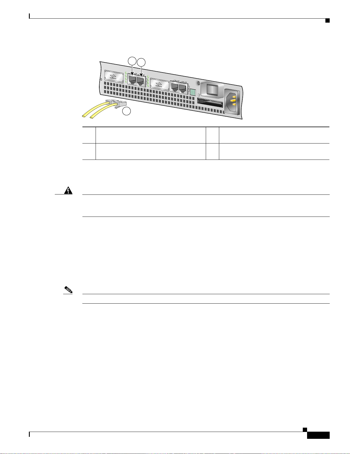
Chapter 2 Rack-Mounting , Tabletop Installation, and Cabling
Figure 2-12 Attaching the Fast Ethernet/Ethernet Cables
1
2
3
Connecting I/O Cables
57696
1 Fast Ethernet/Ethernet port 0 (R J-45
connector)
2 Fast Etherne/Ethernett por t 1 (R J-45
connector)
Attach either o ne o r two Fast Et her net /E ther net 10 /100 cab les to the Fast E the rnet /Ethe rn et port 0 or
port 1.
Warning
T o avoid electric shock, do not connect safety extra-low voltage (SELV) circuits to telephone-network
voltage (TNV) circuits. LAN ports contain SELV circuits, and WAN ports contain TNV circuits. Some
LAN and WAN ports both use RJ-45 connectors. Use caution when connecting cables.
Attaching the GBIC Interface Cables
The GBIC ports su ppo rt I EE E 80 92. 3z ( opt ical Gi gabit E thern et) i n terface s com pl ian t w ith
1000BASESX and 1000BASELX specifications.
After you install the GBIC in the Gigabit Ethernet port, you must attach the cables to the GBIC. The
instructions that follow apply to all supported platforms.
See Appendix A, “Specifications,” for more information on GBIC cabling and cabling specifications.
3 Fast Ethernet cables
Note Optical fiber cables are commercially available; they are not available from Cisco Systems.
Attaching Multimode and Single-Mode Opti cal Fib er Cables
If you ordered a Gigabit Interface Converter (GBIC) with your Cisco 7401ASR router, it is one of three
types listed in Table 2-4:
OL-5419-01 B0
Cisco 7401ASR Installation and Configuration Guide
2-17
Page 52

Connecting I/O Cables
Chapter 2 Rack-Mounting, Tabletop Installation, and Cabling
Table 2-4 GBIC Products, Description, and Operating Distance
Product
Number GBIC De scr ipti on O per atin g Dis ta nc e
GBIC-SX=
or
WS-G5484=
GBIC-LX/LH=
or
WS-G5486=
GBIC-ZX= or
WS-G5487=
Short wavelength
(1000BASESX)
Long wavelength/
long haul
(1000BASELX/LH)
Extended distanc e
(1000BASEZX)
Contains a Class 1 laser of
850 nm for 1000BASESX
(short wavelength)
applications.
Contains a Class 1 laser of
1300 nm for
1000BASELX/LH (long
wavelength) applications.
Contains a Class 1 laser of
1550 nm for 1000BASEZX
(extended wavelength)
applications.
Operates on standard
multimode fiber-optic link
spans of up to 1804 ft
(550 m).
Operates on si ngle-m ode a nd
multimode fiber-optic link
spans of up to 6.2 miles
(10 km).
Operates on ordinary
single-mode fiber-optic link
spans of up to 43.5 miles
(70 km). Link spans of up to
62.1 miles (100 km) are
possible using premium
single-mode fiber or
dispersion-shifted
single-mode fiber.
For cabling specifications, including specific cable maximum distances, see Appendix A,
“Specifications.”.
Caution If you plan to use a GBIC-LX/LH or WS-G5486 at distances greater than 984.25 feet (300 meters) over
50/125-micron or 62.5/125-micron mul timode fiber, you must use the mode-conditioning patch cord to
prevent data tr ansmission pro blems. (See the “Attaching the Mode-Conditioning Patch Cord” section on
page 2-21.)
Warning
Warning
Class 1 laser product.
Class 1 LED product.
2-18
Cisco 7401ASR Installation and Configuration Guide
OL-5419-01 B0
Page 53

Chapter 2 Rack-Mounting , Tabletop Installation, and Cabling
Figure 2-13 GBIC Port Connections
Connecting I/O Cables
1
5
6
7
3
2
4
57580
1 To external 1000BASEX ne twor k 5 TX (G E port 0)
2 1 duplex connector ( TX a nd RX) 6 RX (GE port 0)
3 To external 1000BASEX ne twor k 7 GE p o rt 1
4 2 simplex connect ors
Step 1 Remove the plug from the GBIC so that you can insert the cables. Keep the plug for use should you ever
disconnect the o pti cal fibe r ca ble s.
Warning
Step 2 Attach the appropriate optical fiber cable directly to the SC-type receptacle on the GBIC. You can use
Because invisible laser radiation may be emitted from the aperture of the port when no fiber cable is
connected, avoid exposure to laser radiation and do not stare into open apertures.
either simplex or duplex connectors for most devices. (Figure 2-13 shows a GBIC installed in GE
port 0.)
• For simple x con necto rs, tw o cab les a re requ ire d, one c abl e for tra nsm it (TX) an d a se cond cab le fo r
receive (RX).
• For duplex connectors, only one cab le that ha s both TX and RX connec tors is requ ired.
A mode-conditioning patch c ord can be used with the GBIC-LX/LH or WS-G5486 to allo w reliabl e laser
transmission between the sing le-mode laser source on the GBIC and a multimode optical fiber c able. See
the “Attaching the M od e-Con ditio ning Patch C ord ” section on page 2-2 1 for installation instructions.
Mode-Conditioning Patch Cord Description
A mode-conditioning patch c ord can be used with the GBIC-LX/LH or WS-G5486 to allo w reliabl e laser
transmission between the single-mode laser source on the GBIC and a multimode optical fiber cable.
When an unconditioned laser source designed for operation on single-mode optical fiber is directly
coupled to a multimode optical fiber cable, an effect known as differential mode delay (DMD) might
result in a degradat ion of the moda l b an dwi dth of the op tic al fiber ca ble.
OL-5419-01 B0
Cisco 7401ASR Installation and Configuration Guide
2-19
Page 54

Connecting I/O Cables
Note The mode-conditioning patch cord is requir ed to comply with IEEE standa rds. The IEEE found that lin k
Chapter 2 Rack-Mounting, Tabletop Installation, and Cabling
This degradation results in a dec rease in the link span (the distance between a transmitte r and a recei ver )
that can be supported reliably. The effect of DMD can be overcome by conditioning the launch
characteristics of a laser source. A practica l means of perf orming t his condi tioning is to use a device
called a mode-conditioning patch cord.
A mode-conditioning patch cord is an o ptical f iber cable assembly th at consists o f a pair of optical fiber s
terminated with connector hardware. Specifically, the mode-conditioning patch cord is composed of a
single-mode optical fiber p erma ne ntl y coup led o ff-cente r ( see Offset in Figu re 2-14) to a graded- index
multimode optical fiber. Figure 2-14 shows a diagram of the mo de-c ond ition ing pa tch co rd a ssem bly.
A mode-conditio ning pat ch c ord asse mbly is com pos ed of dupl ex op tica l fibers, i ncl uding a
single-mode-to-multimode offset launch fiber connected to the transmitter, and a second conventional
graded-index multimode optical fiber connected to the receiver. The use of a plug-to-plug patch cord
maximizes the power budget of m ultim ode 1000 BASELX and 1000BASELH links.
distances could not be met with certain types of fiber-optic cable cores. The solution is to launch light
from the laser at a precise offset from the center, which is accomplished by using the mode-conditioning
patch cord. At the output of the patch cord, the GBIC is compliant with the IEEE 802.3z standard for
1000BASELX.
2-20
Cisco 7401ASR Installation and Configuration Guide
OL-5419-01 B0
Page 55

Chapter 2 Rack-Mounting , Tabletop Installation, and Cabling
Attaching the Mode-Conditioning Patch Cord
Figure 2-14 GBIC Mode-Conditioning Patch Cord
Connecting I/O Cables
6
2
RX
TX
3
4 5
1 1
/ / / /
/ /
Offset
87 6
9
1
57011
1 Beige co lor id en tifie r 6 Multimode bar
2 To GE interface 7 Single-mode bar
3 RX 8 Offset
4 TX 9 To cable plant
5 Blue color identifier
To use the mode-conditioning patch cord, follow these steps:
Step 1 Attach the patch cord to the SC-type receptacle on the GBIC. (See Figure 2-13.)
Step 2 Attach the network ends of yo ur patch cord to the appropriate 1000BASEX equipment in your building
cable plant.
Ensure that you connec t the TX and RX ports on one e nd of the patc h cord to the RX and TX por ts
(respectively) on the other en d. Connect TX to RX an d RX to TX.
OL-5419-01 B0
This completes the procedures for connecting the I/O cables.
Cisco 7401ASR Installation and Configuration Guide
2-21
Page 56

Attaching the Alarm Port Cabl e
Attaching the Alarm Port Cable
Figure 2-15 Connecting the Alarm Port Cable
1
57725
1 Alarm port
Chapter 2 Rack-Mounting, Tabletop Installation, and Cabling
If you have an alarm system, attach the alarm cable to the Cisco 7401ASR router alarm port. The alarm
port cable is not provided by Cisco Systems. Insert the cable connector into the alarm port. The cable
connector cann ot be in corr ect ly ins erted into th e ala rm po rt.
The alarm port is used to monitor fatal or severe errors that cause Cisco IOS to crash. The alarm port is
connected to a normally closed solid state relay. Cisco IOS writes to a hardware port and the relay
contact opens. If th e system en ters into a R OMmon o r watch dog reset sta te, the re lay contac ts close. The
closing contac ts al ert the a la rm a nnun cia tor or m onit or t ha t a C isco IOS crash ha s occur re d.
If interfaces fail or other non-fatal errors occur, the alarm port does not respond. Continue to use SNMP
to manage these types of er rors.
For alarm port specifications, see Appendix A, “Specifications,” the “Alarm Port” secti on o n page A-9.
Using the Cable-Management Bracket
Figure 2-16 Securing Interface Cables through the Cable-Management Bracket
2
D
R
E
E
S
I
L
L
M
R
L
B
R
R
E
A
A
A
C
L
N
C
A
X
X
E
X
T
R
X
R
R
X
R
ENHANCED ATM
1
1 Input/output cables 2 Cable-ma nage ment b racket
Secure port adapter in terface ca bles and i nput/o utput cabl es by placin g them thr ough the
cable-management bracket.
Cisco 7401ASR Installation and Configuration Guide
2-22
57581
OL-5419-01 B0
Page 57

Chapter 2 Rack-Mounting , Tabletop Installation, and Cabling
Proceed to the “Connecting Power” section on page 2-23 to complete the installation.
Connecting Power
This section provides the pr ocedure s for conn ecting AC-input and DC -input power to your Cisco
7401ASR router.
Connecting Power
Warning
Warning
This unit might have more than one power cord. To reduce the risk of electric shock, disconnect the
two power supply cords before servicing the unit.
The AC power supply has double pole/neutral fusing.
Connecting AC-Input Power
Figure 2-17 Connecting AC -Inp ut Power
1 AC power connector 2 Power switch
2
57576
1
OL-5419-01 B0
Connect an AC-input power suppl y as fo llows:
Step 1 At the front of the router, check that the power switch is in the off (O) position.
Step 2 Plug the power cabl e into the AC connector on the ro uter.
Step 3 Plug the AC power supply cable into the AC power source.
Note After powering off the router, wait at l east 3 0 se cond s be fore p owering i t on again.
This completes the pr ocedure for connecting AC-input power. Your installation is complete. Proceed to
Chapter 3, “Starting and Configuring,” to start the router and to perform a basi c configurati on.
Cisco 7401ASR Installation and Configuration Guide
2-23
Page 58

Connecting Power
Connecting DC-Input Power
Note The color coding of the DC-inpu t power supply leads d epends on th e color c oding of the DC power
source at your site. Make ce rtain th e lead co lor codi ng you cho ose for the D C-input power supply
matches lead color co ding used at t he DC power source.
Chapter 2 Rack-Mounting, Tabletop Installation, and Cabling
Warning
Warning
When you install the unit, the ground connection must always be made first and disconnected last.
Before completing any of the following steps, and to prevent short-circuit or shock hazards, ensure
that power is removed from the DC circuit. To ensure that all power is OFF, locate the circuit breaker
on the panel board that services the DC circuit, switch the circuit breaker to the OFF position, and
tape the switch handle of the circuit breaker in the OFF position.
Connect a DC-input power supply as follows:
Step 1 At the front of the router, check that the power switch is in the off (O) position.
Step 2 Ensure that no cu rrent is flowing through the D C power supply leads. To ensure that all power is OFF,
locate the circuit breaker on the panel board that services the DC circuit, switch the circuit breaker to
the OFF position, and tape the switch handle of the circuit breaker in the OFF position.
Step 3 Using a w ire stripp er, strip a ppr ox imat el y 0.5 5 i n ch (14 mm) f rom th e –V and +V leads.
Figure 2-18 Attaching the Leads to the DC Plug and the DC Plug to the
DC Connector
2-24
BA
4
3
1
2
1 DC plug 4 Sing le DC power c onn ector
2 Lead 5 Dual DC power connector
3 + and – embossed on connector
Step 4
Insert the –V and +V leads into the DC plug that ships with the Cisco 7401ASR router. The plug allows
you to unplug the DC wires from the power supply without having to unscrew the leads.
a. Orient the plug (1) to the connector (4) as shown in Figure 2-18. The plug inserts only one way.
Notice the symbols, + A – , embossed on the connector (3). Use the symbols a nd the orientation of
the plug to guide you when inserting the leads into the plug.
Cisco 7401ASR Installation and Configuration Guide
BA
50538
5
OL-5419-01 B0
Page 59

Chapter 2 Rack-Mounting , Tabletop Installation, and Cabling
b. Insert the +V lead (2) into the plug as shown in Figure 2-18, a nd tight en t he sc rew to hold th e le ad
to the plug.
c. Insert the –V into the plug as shown in Figure 2-18, and tighten the scre w to hold the lead to the plug.
Step 5 If yo u have a dual D C p ower suppl y, repeat Step 4 fo r t h e sec on d p lug.
Step 6 Inser t the DC plug int o the DC power conne ctor on th e chassis. If you have a dual DC power supply,
insert the second DC plug into the DC power connector.
Step 7 Sw itch the c ircu i t brea ker t o th e on po siti on .
Note After powering off the router, wait at l east 3 0 se cond s be fore p owering i t on again.
This completes the procedure for connec tin g DC-inpu t power . Your installation is complete. Proceed to
Chapter 3, “Starting and Configuring,” to start the router and to perform a basi c configurati on.
Connecting Power
OL-5419-01 B0
Cisco 7401ASR Installation and Configuration Guide
2-25
Page 60

Connecting Power
Chapter 2 Rack-Mounting, Tabletop Installation, and Cabling
2-26
Cisco 7401ASR Installation and Configuration Guide
OL-5419-01 B0
Page 61

CHAPTER
3
Starting and Configuring
This chapter describes how to start the syst em and per form a basi c configurati on for your
Cisco 7401ASR rout er. The chapter co ntai n s the f ollowing sec ti ons:
• Functional Overview, page 3-1
• Checking Conditions Prior to System Startup, page 3-9
• Starting the System and Observing Initial Conditions, page 3-9
• Configuring a Cisco 740 1ASR Rout er, page 3-10
• Performing Other Configurati on Tasks, page 3-21
• Replacing or Rec overing a L ost Password, page 3-22
• Viewing Your System Configuration, page 3-25
• Performing Complex Configurations, page 3-27
This chapter guides you through a basic router co nfigur ation, which is sufficient for you to access your
network. Complex configurat ion pr oced ure s are beyond the sco pe of thi s pub lica tio n and c an b e fou nd
in the modular configuration and modular command reference publications in the Cisco IOS software
configuration docu ment ation se t th at c or res ponds to the software r eleas e in stall ed o n your C isco
hardware.
To configure a Ci sco 74 01A SR ro uter f rom a c on sole , you ne e d to c onn ect a t erm in al to t h e rou t er
console port.
Functional Overview
This section provides a functional overview of the Cisco 7401ASR router. It describes the numbering
and addressing scheme of the port ada pter for th e router, the environmental monit oring and reporti ng
functions, and onli ne insert ion and removal (OIR). Thes e descr ipti ons help you be come fami liar wi th
the capabilities of the Cisco 7401ASR router.
Chassis Slot and Logical Interface Numbering
In the Cisco 7401ASR router, the port-adapter-slot-number is the chassis slot in which a port adapter is
installed, whereas the logical-interface-number is the physical location of the interface port on a port
adapter.
The port adapter slot in the Cisc o 7401ASR router is num bered slot 1. Port adapte r slot 0 is always
reserved for logical slots 10 |10 0|1000 on the sy stem bo ard.
OL-5419-01 B0
Cisco 7401ASR Installation and Configuration Guide
3-1
Page 62

Functional Overview
Chapter3 Starting and Configuring
The Media Acce ss Co ntro l (M AC) or hardwar e ad dress i s a stand ardi zed da ta link la yer a ddr es s tha t i s
required for certain net work inter face types. Th ese ad dresses are n ot used by other devices in the
network; they are specific and unique to each port. The Cisco 7401ASR router uses a specific method to
assign and control the MAC addresses of its port adapters. For a description of the MAC address, see the
“MAC Address” section on page 3-3.
Yo u can iden tify port a dapter slots by using sof tware comm ands. To display information about all port
adapter slot s, us e th e sh ow inte rfaces command. To display information about a specific port adapter
slot, use the show interfaces command with the port adapter type and slot number in the format
show interfaces port-adapter-type slot-n umbe r/port-number. If you abbreviate the command (sh int)
and do not specify port adapter type and slot number (or arguments), the system interprets the command
as show interfaces and displays the status of all port adapt ers and port s.
The following exam pl e s h ows how the show interfaces command, used w ithout argument s, d isp lay s
status information (includ ing the phys ica l port adapt er num ber) for ea ch port adapte r in a Cisco
7401ASR router.
In the following example, most of the status information for each interface is omitted.
Router# show interfaces
GigabitEthernet0/0 is up, line protocol is down
Hardware is i82543 (Livengood), address is 0000.0000.0000 (bia 0000.0000.0000)
Internet address is 1.1.1.2
MTU 1500 bytes, BW 1000000 Kbit, DLY 10 usec,
reliability 255/255, txload 1/255, rxload 1/255
(display text omitted)
GigabitEthernet0/1 is administratively down, line protocol is down
Hardware is i82543 (Livengood), address is 0000.0000.0000 (bia 0000.0000.0000)
MTU 1500 bytes, BW 1000000 Kbit, DLY 10 usec,
reliability 255/255, txload 1/255, rxload 1/255
(display text omitted)
Serial1/0:0 is down, line protocol is down
Hardware is Multichannel T1
MTU 1500 bytes, BW 1536 Kbit, DLY 20000 usec,
reliability 255/255, txload 1/255, rxload 1/255
(display text omitted)
alarm present
Timeslot(s) Used:1-24, subrate:64Kb/s, transmit delay is 0 flags
Yo u can also use argume nts such as the int erfac e t ype ( Ethe rn et, Token Ring, ATM, and so for th) an d
the port address (slot-number/port-number) to display information about a specific interface only.
The following example shows the display for the first port on the Gigabit Ethernet port adapter in the
port adapter slot (1):
Router# show interface g1/0
GigabitEthernet1/0 is up, line protocol is down
Hardware is i82543 (Livengood), address is 0000.0000.0000 (bia 0000.0000.0000)
Internet address is 1.1.1.2
MTU 1500 bytes, BW 1000000 Kbit, DLY 10 usec,
reliability 255/255, txload 1/255, rxload 1/255
Encapsulation ARPA, loopback not set
Keepalive set (10 sec)
Full-duplex mode, link type is autonegotiation, media type is SX
output flow-control is off, input flow-control is off
ARP type:ARPA, ARP Timeout 04:00:00
3-2
Cisco 7401ASR Installation and Configuration Guide
OL-5419-01 B0
Page 63

Chapter 3 Starting and Configuring
For complete descriptions and inst ructions of the commands used to configure your C isco 7401ASR
router, refer to the Cisco IOS Configuration Fundamental s Co nfiguration Gu id e a nd Cisco IOS
Configuration Fundamental s Co mma nd Re ference pu bli cati ons, whi ch ar e available o nli ne, o n th e
Documentation CD-ROM, and in print.
MAC Address
All LAN interfaces (por ts) require unique MA C addresses, also known as hardware addresses. T ypically ,
the MAC address of an interface is stored on a memory component that resides dire ctly on the interface
circuitry; however, the OIR feature r e quire s a di fferen t me thod . (For a d escri ptio n of O I R, see the
“Online Insertion and Removal” section on page 3-3.)
Using OIR you can remove a port adapter and replace it with another identically configured one. If the
new port adapter matches the port adapter you removed, the system immediately brings it online. In order
to enable OIR, an address all oc ato r with un iqu e MAC addresses is sto re d in an EEPROM on the system
board. Each add re ss is re ser ved for a sp eci fic port an d sl o t in th e rout er regardle ss o f wh ethe r a po rt
adapter resides in t hat slot. T he M AC address fo r the po rt a da pte r slo t i n th e Cisc o 7401 A SR is slo t 0.
Yo u can remove a port adap ter and inse rt it into ano ther route r without ca using the MAC addresses to
move around the network or be a ssign ed to mu ltipl e d evices.
Functional Overview
Note that if the M AC addresses wer e sto re d on ea c h po rt a dapt er, OIR would not funct ion be cause yo u
could never replace one port adapter wit h an identica l one; the MAC addresses would always be
different. Also, each time a port adapter was replaced, other devices on the network would have to update
their data structures with the new addre ss. If the other devices did not update qu ic kly enough, the same
MAC address could appear in more than one device at the same time.
Note Storing the MAC addresses for every slot in one central location means the addresses stay with the
memory device on which they are stored.
Online Insertion and Removal
All port adapters a nd se rv ice a dapt ers in t he C isco 74 01ASR rou ter s su pport onl ine i nsert ion and
removal (OIR). This function allows you to install and replace port adapters and service adapters while
the router is ope rat ing; you do n ot ne ed to not ify the sof twar e or shu t down the sy stem power. This
provides a method that is seamless to end users on the network, maintains all routing information, and
preserves sessions.
The following is a functional des cript ion of OIR for bac kgroun d informa tion only; for specific
procedures for installing and replacing a port adapter or service adapter in a Cisco 7401ASR router, refer
to the configuration note that ships with each port adapter or service adapter.
Each port or service adapter has a bus connector that connects it to the router. The connector has a set
of tiered pins in three lengths that send specific signals to the system as they make contact with the port
adapter or service adapter. The system assesses the signals it receives and the order in which it receives
them to determine if a port adapter or service adapter is being remo ved or inserte d into the system. From
these signals, the system determines whether to reinitialize a new interface or shut down a removed
interface.
OL-5419-01 B0
For example, when you insert a port adapte r or service ad apt er, the longest pins make conta ct with t he
port adapter or service adapter first, and the shortest pins make contact last. The system recognizes the
signals and the sequence in which it receives them.
Cisco 7401ASR Installation and Configuration Guide
3-3
Page 64

Functional Overview
When you remove or insert a port adapte r or servic e adap ter in a Cisc o 7401ASR router, the pins send
signals to notify the system, which then performs as follows:
1. Rapidly scans the system for co nfiguration cha nges.
2. Initializes all newly inserted port adapter or service adapter, noting any removed interfaces and
placing them in the administratively shutdown state.
3. Brings all previously configured interfaces on the port adapter back to the state they were in when
they were remo ved. Any newly inserted interface is put in the administratively sh u tdown state, as if
it was present (but not configured) at boot time. If a similar port adapter type is reinserted into a slot,
its ports are configured and brough t online up t o the port coun t of the origi nal port ad apter. (A
service adapter has no co nfigurable ports.)
Environmental Monitoring and Reporting Functions
Environmental monitoring and repor ting fun ctions al low you to maintain norm al syste m operati on by
identifying and resolvi ng advers e conditi ons prior to loss of oper ation. Th e environmental monito ring
functions constantly monitor the internal chassis air temperature and DC supply voltages and currents.
If conditions reac h s hutdown th resh olds, the sy stem shut s d own to avoid equipm ent da mage f rom
excessive heat. The reporting functions peri odically l og the values of measu red para meters so tha t you
can retrieve them for analysis later, and the reporting functions display warnings on the console if any
of the monitored pa ram eters exceed defined th re sholds.
Chapter3 Starting and Configuring
Environmental Monitoring
The environmental monitoring functions use two sensors, Sensor 1 near the processor, and Sensor 2, near
the power supply. If the air temperature exceeds a defined threshold, the system controller displays
warning messages on the console terminal, and if the temperature exceeds the shutdown threshold, the
system controller shuts down the system. The system stores the present parameter measurements for both
temperature and DC voltage in NVR AM so you ca n ret rieve them lat er a s a repor t of th e la st shut d own
parameters.
If an internal power supply tem p eratu re or voltage reaches a critical level, the power supply shuts do w n
without any interaction with the system processor.
The environmental monitoring functions use the following levels of status conditions to monitor the
system:
• Normal—All monitored parameters are within normal tolerances.
• Warning—The system has exceeded a specified threshold. The system continues to operate, but
operator action is recommended to bring the system back to a normal state.
• Critical—An out-of-to ler ance te mp erat ur e or voltag e co nditi on exists. The sy stem c on tinu es t o
operate; however, the system is approaching shutdown. Immediate operat or action i s require d.
• Shutdown—The processor has detected a temperature condition that could result in physical damage
to system components and has disabled DC power to all internal components. This condition
requires immediate operator action. All DC power remains disabled until you toggle the power
switch. Before any shutdown, the system logs the status of monitored parameters in NVRAM so you
can retrieve it later to help determine the cause of the problem.
• Power supply shutdown—The power supply detected an internal out-of-tolerance overvoltage,
overcurrent, or temperature condition and shut itself down. All DC power remains disabled until you
toggle th e power s wit ch.
3-4
Cisco 7401ASR Installation and Configuration Guide
OL-5419-01 B0
Page 65

Chapter 3 Starting and Configuring
Table 3-1 lists the typical temperature thresholds for the Cisco 7401ASR router, and Table 3-2 lists the
DC power thresholds for the normal, warning, and critical (power supply -monitore d) levels.
Table 3-1 Typical Processor-Monitored Temperature Thresholds
Parameter High Warning High Critical Shutdown
Sensor 1 (near processor) 122
Sensor 2 (near power supply) 107
Note Table 3-2 shows output from the show environment table co mman d.
Table 3-2 Typical Power Supply-Monitored DC-Voltage Thresholds
Parameter Low Critical Low Warning High Warning High Critical
+1.8V (PXF) +1.61 +1.66 +1.93 +1.98
+1.8V (CPU) +1.61 +1.66 +1.93 +1.97
+2.50V +2.24 +2.31 +2.68 +2.75
+3.30V +2.96 +3.04 +3.54 +3.62
+5.0V +4.50 +4.62 +5.36 +5.50
+5.20V +4.68 +4.80 +5.58 +5.72
+12.25V +11.03 +11.32 +13.16 +13.49
–12.00V –10.82 –11.10 –12.91 –13.20
o
F (50oC) 140oF (60oC) 149oF (65oC)
o
F (42oC) 125oF (52oC) 134oF (57oC)
Functional Overview
Reporting Functions
The Cisco 7401ASR router displays warning messages on the console if chassis interface-monitored
parameters exceed a de sire d th reshol d . You can also retrieve and display environmental sta tus r eport s
with the show environment, show environment all, show environment last, and show environment
table commands. Parame ters are measur ed and reporti ng functi ons are updat ed eve ry 60 second s. A brief
description of each of the se comm ands foll ows.
Caution To prevent overheating the chassis, ensure that your system is drawing cool inlet air. Overtemperature
conditions can occur if th e system is drawing in the exhaust air of other eq uipmen t. Ensure adequat e
clearance around the si des of the ch assis so that co oling air can flow through the cha ssis inter ior
unimpeded and exhaust air exits the chassis and is not drawn into the inlet vent of another device.
The show environment comm a nd di spla ys repor ts of the c urre nt e nvironmental s yst em stat us. T he
report displays parameters that are out of the normal values. No parameters are displayed if the system
status is normal. The example that follows shows the display for a system in which all monitored
parameters are within normal range:
Router# show environment
All measured values are normal
OL-5419-01 B0
Cisco 7401ASR Installation and Configuration Guide
3-5
Page 66

Functional Overview
Chapter3 Starting and Configuring
If the environmental status is no t normal, the system reports the worst-case status level. Following is a
sample overvoltage warning:
Router# show environment
Warning:+3.45 V measured at +3.27 V
The show environment last command retrieves and displays the NVRAM log, which shows the reason
for the last system shutdown (if the shutdown was related to voltage or temperature) and the
environmental status at that time. Air temperature is measured and displayed, and the DC voltage
supplied by the power supply is also displayed.
Following is sample output of the show environment last command:
Router# show environment last
chassis inlet previously measured at 30C/86F
chassis outlet 1 previously measured at 28C/82F
chassis outlet 2 previously measured at -1C/31F
chassis outlet 3 previously measured at -1C/31F
+3.45 V previously measured at +3.27
+5.15 V previously measured at +5.01
+12.15 V previously measured at +12.34
-11.95 V previously measured at -12.41
last shutdown reason - power supply shutdown
The show environment tabl e command displays the temperature and voltage thresholds for each
temperature sensor and for each monitored status level. These thresholds are related to those listed in
Table 3-1 and Table 3-2. The display also lists the shutdown threshold for the system.
Following is sample output of the show environment table command for a Cisco 7401ASR router:
Router# show environment table
Sample Point LowCritical LowWarning HighWarning HighCritical
chassis inlet 40C/104F 50C/122F
chassis outlet 1 43C/109F 53C/127F
chassis outlet 2 75C/167F 75C/167F
chassis outlet 3 50C/122F 60C/140F
+3.45 V +3.26 +3.34 +3.55 +3.63
+5.15 V +4.86 +4.99 +5.31 +5.43
+12.15 V +11.39 +11.67 +12.62 +12.91
-11.95 V -9.52 -10.73 -13.16 -14.38
System shutdown for chassis outlet 1 58C/136F
System shutdown for chassis outlet 3 65C/149F
Note Temperature ranges and values are subject to change.
The sho w environment all command displays an extended report that includes temperature readings and
voltage readings. The show environment all command also displays a re por t showing w hic h power
supply slots are occ upie d and w h ich are empt y.
Following is sample output of the show environment all command.
3-6
With AC power supply installed:
Router# show environment all
Power Supplies:
Power supply 1 is Internal AC Power Supply. Unit is on.
Power supply 2 is unmeasured.
Cisco 7401ASR Installation and Configuration Guide
OL-5419-01 B0
Page 67

Chapter 3 Starting and Configuring
Temperature readings:
chassis inlet measured at 29C/84F
chassis outlet measured at 26C/78F
Voltage readings:
+1.8 V (PXF) measured at +1.79 V
+1.8 V (CPU) measured at +1.77 V
+2.50 V measured at +2.47 V
+3.30 V measured at +3.28 V
+5.00 V measured at +4.98 V
+5.20 V measured at +5.18 V
+12.25 V measured at +12.21 V
-12.00 V measured at -12.15 V
Fans:
Fan 1 is believed to be working
Fan 2 is believed to be working
Fan 3 is believed to be working
Fan 4 is believed to be working
Fan 5 is believed to be working
With a single 24V DC power supply installed:
Router# show environment all
Functional Overview
Power Supplies:
Power supply 1 is Internal 24VDC Power Supply. Unit is on.
Power supply 2 is unmeasured.
Temperature readings:
chassis inlet measured at 35C/95F
chassis outlet measured at 29C/84F
Voltage readings:
+1.8 V (PXF) measured at +1.79 V
+1.8 V (CPU) measured at +1.77 V
+2.50 V measured at +2.47 V
+3.30 V measured at +3.28 V
+5.00 V measured at +4.98 V
+5.20 V measured at +5.18 V
+12.25 V measured at +12.36 V
-12.00 V measured at -12.15 V
Fans:
Fan 1 is believed to be working
Fan 2 is believed to be working
Fan 3 is believed to be working
Fan 4 is believed to be working
Fan 5 is believed to be working
With a single 48V DC power supply installed:
Router# show environment all
Power Supplies:
Power supply 1 is Internal 48VDC Power Supply. Unit is on.
Power supply 2 is empty.
OL-5419-01 B0
Temperature readings:
chassis inlet measured at 34C/93F
chassis outlet measured at 28C/82F
Voltage readings:
+1.8 V (PXF) measured at +1.79 V
+1.8 V (CPU) measured at +1.77 V
Cisco 7401ASR Installation and Configuration Guide
3-7
Page 68

Functional Overview
Chapter3 Starting and Configuring
+2.50 V measured at +2.47 V
+3.30 V measured at +3.28 V
+5.00 V measured at +4.98 V
+5.20 V measured at +5.18 V
+12.25 V measured at +12.36 V
-12.00 V measured at -12.15 V
Fans:
Fan 1 is believed to be working
Fan 2 is believed to be working
Fan 3 is believed to be working
Fan 4 is believed to be working
Fan 5 is believed to be working
With dual 48V DC power supplies installed:
Router# show environment all
Power Supplies:
Power supply 1 is Redundant 48VDC Power Supply. Unit is on.
Power supply 2 is empty.
Temperature readings:
chassis inlet measured at 34C/93F
chassis outlet measured at 28C/82F
Fan Failures
Voltage readings:
+1.8 V (PXF) measured at +1.79 V
+1.8 V (CPU) measured at +1.77 V
+2.50 V measured at +2.47 V
+3.30 V measured at +3.28 V
+5.00 V measured at +4.98 V
+5.20 V measured at +5.18 V
+12.25 V measured at +12.26 V
-12.00 V measured at -12.15 V
Fans:
Fan 1 is believed to be working
Fan 2 is believed to be working
Fan 3 is believed to be working
Fan 4 is believed to be working
Fan 5 is believed to be working
When the system power is o n, al l five fans should be o pe rat iona l. T he s ystem con tin ue s to ope rat e if a
fan fails. When a fan fails, the system displays the following message:
router: 00:03:46:%ENVM-3-BLOWER:Fan 2 may have failed
If the air tempera ture excee ds a de fined thre sho ld, the s yst em c ontr oller di splays wa rnin g m essages on
the console terminal, and if the temperature exceeds the shutdown threshold, the system controller shuts
down the system.
3-8
If the system d oes shut down bec au se the t empe r atur e exce ed ed the shut down th r esh old, th e s y st em
displays the following message on the c onsole scr een and in the environment display wh en the system
restarts:
Queued messages:
%ENVM-1-SHUTDOWN: Environmental Monitor initiated shutdown
Cisco 7401ASR Installation and Configuration Guide
OL-5419-01 B0
Page 69

Chapter 3 Starting and Configuring
Checking Conditions Prior to System Startup
For complete descriptions and instructions for the environmental monitor commands, refer to the Cisco
IOS Configuration Fund amen t als Co nfiguration Guid e a nd Cisco IOS Configuration Fundamentals
Command Reference publications, w hic h a re available on line, on the Do cu me ntat ion CD- ROM, and i n
print.
Checking Conditions Prior to System Startup
Check the following cond itio ns b efore y ou st ar t yo ur ro uter :
• The port adapter is inserted in its slot and the port adapter latch is in the locked position.
• The network interface cable is connected to the port adapter.
• A CompactFlash Disk is installed.
• The console terminal is turned on.
You are now ready to start your router. Proceed to the section “Starting the System and Observing Initial
Conditions.”
Starting the System and Observing Initial Conditions
After installing you r C isco 7401ASR router a nd co nne ct ing c abl es, star t t he r oute r as fol lows:
Step 1 At the fron t of the route r, place the power switch on the power supply in the on (|) positio n.
Step 2 Listen for the fans; y ou shou l d im medi atel y hear the m opera ting.
Step 3 During the boot proce ss, ob se rve the sy st em L EDs. T he L EDs on the po rt a dapt er go on a nd off in
irregular sequence. Th ey ma y g o o n, go ou t , an d g o o n aga in f or a sho rt tim e. On t he r out er, the gr een
STATUS LED com es on a nd st ays o n.
Step 4 Observe the initialization process. When the system boot is complete (a few seconds), the processor
begins to initialize the port adapter and the I/O subsystem. During this initialization, the LEDs on the
port adapter probably will flash on and off.
The enabled LED on the port adapter goes on when initialization is completed, and the console screen
displays a script a nd sys tem bann er simi la r to the f ollowing:
Cisco Internetwork Operating System Software
IOS (tm) 7400 Software (C7400-JS-M), Version 12.2(V99.1)Copyright (c) 1986-2001 by cisco
Systems, Inc.
Compiled Sat 19-May-01 11:31 by
Image text-base:0x60008960, data-base:0x617CA000
OL-5419-01 B0
Cisco 7401ASR Installation and Configuration Guide
3-9
Page 70

Configuring a Cisco 7401ASR Router
Step 5 When you start up the router for the first time, the system automatically enters the setup facility, which
determines which port ada pter is inst alled and prompts you fo r configurat ion informa tion. On the
console terminal, af ter the system di splay s the syste m ba nner a nd hardwa re co nfigurat ion, you will see
the following System Co nfigurati on D ial og pr om pt:
At any point you may enter a questions mark ‘?’ for help.
Use ctrl-c to abort configuration dialog at any prompt.
Default settings are in square brackets ‘[]’.
continue with configuration dialog? [yes]:
Yo u have the opt ion of proc ee ding wi th t he setu p facility to configure the interfaces, or exiting from
setup and using con figurati on co mman ds t o c onfigu re glo bal (sys tem -wi de) a nd int erfac e-spe ci fic
parameters. You do not have to configure the inte rfaces immedi ately; however, you cannot enable the
interfaces or connect them to any networks until you have configured them.
Many of the port adapte r LED s do no t go on un t il yo u have configured the int erfac es. To verify correct
operation of each interface, complete the first-time startup procedures and configuration, and then refer
to the configurati on no te for t he p ort ad apte r fo r LE D de sc ripti ons a nd t o c hec k th e stat us of t he
interfaces.
Chapter3 Starting and Configuring
--- System Configuration Dialog ---
If the system does not complete each of the steps in the startup procedure, proceed to Chapter 5,
“Troubleshooting,” for t r oublesho ot ing reco mm en datio ns a nd proc e dures.
Configuring a Cisco 7401ASR Router
Yo u can co nfigure you r C isco 7401ASR rout er usi n g one of th e pro cedu re s d escribe d in t h e fol lowing
sections:
• Performing a Basic C onfiguratio n U sing A utoI nstall , pa ge 3-1 1
• Performing a Basic C onfiguration U sing the Set up Facility, page 3-11
• Performing a Basic C onfigurati on U si ng G loba l Co nfigurati on Mode , page 3-20
Follow the procedure tha t best fits the n eeds of yo ur ne twork configura tio n.
Note Yo u need to ac quir e t he c orre ct n etwo rk ad dre sses f ro m y our sy stem a dm inistr ato r or co nsult y our
network plan to determ ine corr ect addr esses be fore you can compl ete the ro uter configurat ion.
Before continuing th e configurati on process, check th e current state of the router by entering the show
version command. The show version command displays the release of Cisco IOS software that is
available on the router. Sample output of the show version command appears in the “Viewing Your
System Configuration” section on page 3-25.
3-10
Cisco 7401ASR Installation and Configuration Guide
OL-5419-01 B0
Page 71

Chapter 3 Starting and Configuring
Performing a Basic Configuration Using AutoInstall
The AutoInstall process is designed to configure the Cisco 7401ASR router automatically after
connection to yo ur WAN. For AutoInstall to work proper ly, a TCP/IP host on yo ur net work m ust be
preconfigured to provide t h e re quir ed configur ation files. T he T CP/ IP host may exist anywher e on t he
network as long as the following two conditions are maintained:
1. The host must be on the remo te side of the rout er synchr onous seri al conne ction to the WAN.
2. User Datagram Protocol (UDP) broadcasts to and from the router and the TCP/IP h ost are enabled.
This functionality is coordinated by your system administrator at the site where the TCP/IP host is
located. You should not use AutoInstall unless the requ ired files are av a ilable o n the T CP/IP host. Ref er
to the publications Cisco IOS Configuration Fundamental s C onfiguration Gu ide and Cisco IOS
Configuration Fundamental s Co mma nd Re ference for i nformat ion about how AutoIn stall works.
Complete the fo llowing steps to prep ar e yo ur Cisc o 7 401 ASR r outer f or the Auto Inst all proc ess:
Step 1 Attac h the ap pro pria te synchr ono us ser ial c a ble to sync hrono us s er ial i n terface 0 on the rou ter.
Step 2 Turn the power switch on the power supply to the on (|) po sition. (This action turns on AC power to the
router.)
Configuring a Cisco7401ASR Router
Note After powering off the router, wait at least 3 0 sec onds be f ore p owering it on a gain.
The router loads the operating system image from Flash memory. If the remote end of the WAN
connection is connec ted and pro perly co nfigured , the AutoIn stall process begins .
Once the AutoInstall process is completed, use the copy running-config startup-config command to
write the configuration data to the router’s nonvolatile random-access memory (NVRAM). Perform the
following step to complete this task.
Step 3 At the # prompt, enter the following command:
Hostname# copy running-config startup-config
Note Completing Step 3 saves the configuration settings that the AutoInstall process created to NVRAM. If
you fail to do this, your configuration will be lost the next time you reload the router.
Performing a Basic Configuration Using the Setup Facility
If you do not pl an to use Aut o Insta ll, d o n ot c on ne ct the ro uter ’s serial (WAN) cable to the channel
service unit/data service unit (CSU/DSU). If the WAN cable is not connected, the router boots from
Flash memory and goes automatically into the setup facility.
OL-5419-01 B0
Note You can run the setup facility any time you ar e a t th e e nabl e p rom pt (# ) by e nte ri ng the setup command.
Cisco 7401ASR Installation and Configuration Guide
3-11
Page 72

Configuring a Cisco 7401ASR Router
If the serial (WAN) cable is connected to the CSU/DSU and the router does not have a configuration
stored in NVRAM, the router attemp ts to run AutoInstall at sta rtup. The router may tak e se vera l minutes
to determine that AutoInstall is not set up to a remote TCP/IP host. Once the router determines that
AutoInstall is not configured, it defaults to the setup facility.
Configuring Global Parameters
When you first start the setup program, you must configure the global parameters. These parameters are
used for controlling system-wide settings. Complete the following steps to enter the global parameters:
Step 1 Conne ct a consol e termin al to the console port, and t hen boot th e router.
The system boots from Flash memory. The following information appears after about 30 seconds. When
you see this information, you have successfull y booted yo ur router :
Restricted Rights Legend
Use, duplication, or disclosure by the Government is
subject to restrictions as set forth in subparagraph
(c) of the Commercial Computer Software - Restricted
Rights clause at FAR sec. 52.227-19 and subparagraph
(c) (1) (ii) of the Rights in Technical Data and Computer
Software clause at DFARS sec. 252.227-7013.
Chapter3 Starting and Configuring
cisco Systems, Inc.
170 West Tasman Drive
San Jose, California 95134-1706
Cisco Internetwork Operating System Software
IOS (tm) 7400 Software (C7400-JS-M) Version 12.2
Copyright (c) 1986-2001 by cisco Systems, Inc.
Compiled Fri 19-May-01 13:12 by Biff
Image text-base:0x60008960, data-base:0x617CA000
cisco 7401ASR (NSE) processor (revision A) with 245760K/16384K bytes of memory.
Processor board ID 4294967295
R7000 CPU at 375Mhz, Implementation 39, Rev 3.3, 256KB L2, 2000KB L3 Cache
1 slot ASR midplane, Version 2.0
Last reset from power-on
Bridging software.
X.25 software, Version 3.0.0.
SuperLAT software (copyright 1990 by Meridian Technology Corp).
TN3270 Emulation software.
PXF processor tmc has been reset.
8 Ethernet/IEEE 802.3 interface(s)
2 Gigabit Ethernet/IEEE 802.3 interface(s)
509K bytes of non-volatile configuration memory.
64256K bytes of ATA PCMCIA card at slot 0 (Sector size 512 bytes).
8192K bytes of Flash internal SIMM (Sector size 256K).
Press RETURN to get started!
3-12
The first two sections of the co nfigurati on script (t he ban ne r an d the i nsta lled ha rdware ) appe a r only a t
initial system startup. On subsequent uses of the setup facility, the script begins with a System
Configuration Dialog as shown in the following example.
Cisco 7401ASR Installation and Configuration Guide
OL-5419-01 B0
Page 73

Chapter 3 Starting and Configuring
--- System Configuration Dialog ---
At any point you may enter a question mark '?' for help.
Use ctrl-c to abort configuration dialog at any prompt.
Default settings are in square brackets '[]'.
Step 2 When asked if you want to enter the initial configuration dialog and see the current interface summary,
enter yes or press Return:
Would you like to enter the initial configuration dialog? [yes]:
First, would you like to see the current interface summary? [yes]:
In the following exampl e, t he summ ar y shows a Ci sco 7401ASR router at first- time star t up; th at is,
nothing is configured .
Any interface listed with OK? value "NO" does not have a valid configuration
Interface IP-Address OK? Method Status Protocol
ATM1/0 unassigned NO unset down down
FastEthernet2/0 unassigned NO unset down down
Step 3 Choose which protocols to support on your interfaces. For Internet Protocol (IP)-only installations, you
can accept the d efa ult values fo r mo st of t he q ue stio ns. A t ypi cal configu rat ion u si ng IP, IPX, and
AppleTalk follows and continues through Step 8:
Configuring global parameters:
Configuring a Cisco7401ASR Router
Enter host name [Router]:
Step 4 Enter enable secret, enable, and virtual terminal passwords:
The enable secret password is a one-way cryptographic secret
password used instead of the enable password when it exists.
Enter enable secret: barney
The enable password is used when there is no enable secret
password and when using older software and some boot images.
Enter enable password: betty
Enter virtual terminal password: fred
Step 5 The Simpl e Network Managemen t Protocol (SNMP) is the most w idely suppor ted open st andard for
network managemen t. I t pr ovides a mean s to ac cess a nd se t co nfigurat ion a nd ru n-t ime par am eters of
routers and communica tion servers. SNMP defines a set of func tions that ca n be used to mon itor and
control network elem ent s.
Enter yes or press Return to accept SNMP management; enter no to refuse it:
Configure SNMP Network Management? [yes]:
Community string [public]:
Step 6 For the following queries, do not enable VINES, LAT, DECnet, CLNS, bridging, XNS, or Apollo:
Configure Vines? [no]:
Configure LAT? [no]:
Configure DECnet? [no]:
Configure CLNS? [no]:
Configure bridging? [no]:
Configure XNS? [no]:
Configure Apollo? [no]:
OL-5419-01 B0
Cisco 7401ASR Installation and Configuration Guide
3-13
Page 74

Configuring a Cisco 7401ASR Router
Step 7 For the following queries, enable routing on AppleTalk and IPX:
Configure AppleTalk? [no]: yes
Multizone networks? [no]: yes
Configure IPX? [no]: yes
Step 8 In most cas es you use IP rou ting. If you ar e using IP rout ing, you must also select an in terior rou ting
protocol. Y ou can specify only one of two interior routing protocols to operate on your system using the
setup facility: Interior Gateway Routing Protocol (IGRP) or Routing Information Protocol (RIP).
To configure IP routing, enter yes (the default) or press Return, and then select an interior routing
protocol:
Configure IP? [yes]:
Configure IGRP routing? [yes]:
Your IGRP autonomous system number [1]: 15
The following sample display includ es a continuo us listing of all configuration parameters se lected in
Step 3 through Step 8. Only I P, IPX, and AppleTalk are the selected prot ocol s f or t his exampl e.
Configuring global parameters:
Enter host name [Router]: router
Chapter3 Starting and Configuring
The enable secret is a one-way cryptographic secret used
instead of the enable password when it exists.
Enter enable secret: barney
The enable password is used when there is no enable secret
and when using older software and some boot images.
Enter enable password: betty
Enter virtual terminal password: fred
Configure SNMP Network Management? [yes]:
Community string [public]:
Configure Vines? [no]:
Configure LAT? [no]:
Configure AppleTalk? [no]: yes
Multizone networks? [no]: yes
Configure DECnet? [no]:
Configure IP? [yes]:
Configure IGRP routing? [yes]:
Your IGRP autonomous system number [1]: 15
Configure RIP routing? [no]:
Configure CLNS? [no]: n
Configure bridging? [no]:
Configure IPX? [no]: yes
Configure XNS? [no]:
Configure Apollo? [no]:
Step 9 Save your settings to NVRAM. (See the “Saving the Running Configuration to NVRAM” section on
page 3-21.) If you do not save the configuratio n settings you cre ated in the rou ter usin g configurati on
mode and the setup facility, your configuration will be lost th enext time yuou load the router.
3-14
Cisco 7401ASR Installation and Configuration Guide
OL-5419-01 B0
Page 75

Chapter 3 Starting and Configuring
Configuring a Cisco7401ASR Router
Configuring the Native Gigabit Ethernet and Fast Ethernet/Ethernet Interfaces
The Cisco 7401ASR router reports both the Fast Ethernet/Ethernet and the Gigabit Ethernet ports as GE
0/0 and GE 0/1. Before configuring eit her port typ e, you must first use the media-type interface
command to select the media type, either Gigabit Ethernet (gbic) or Fast Ethernet/Eth ernet (rj45).
Changing the Media Type
Step 1 To be able to use a particular me dia port, use Ci sco IOS to select the m ed ia t ype. This i s don e by usin g
the media-type interface command:
media-type { gbic | rj45 }
Example:
interface GigabitEthernet 0/0
media-type rj45
end
Step 2 After changing the media type, co nf ig ure the s peed an d du plex to app ropri ately m atch the new interface
characteristics. Changing the speed and duplex of a Cisco 7401ASR router Gigabit Ethernet interface is
done using the speed and duplex interface commands.
Note These commands are only applicable when using the RJ-45 media.
speed { 10 | 100 | 1000 | auto }
duplex { full | half | auto }
The following speed/duplex settings are supported:
Media Type Speed Duplex
-----------------------------------------------------RJ45 10, 100, auto full, half, auto
GBIC ignored (1000) ignored (full) (By default on this interface)
-------------------------------------------------------
When using the GBIC media, there is also the additional negotiation auto command that is used to
enable the IEEE 801. 1z Gigabi t Etherne t (1000 Mbps) auton egotiation pr otocol .
Step 3 To turn thi s autone got iation f eature o f f (it is on by d efau lt), issue the i nterf ace com mand no negotiation
auto. This is u sef ul f or c onn ect ing to o th er G igab i t Eth er ne t e quipm en t t hat do es not sup port 80 2.1 z
autonegotiation.
Note The negotiation auto feature is not supported when usin g the media type rj-45 and will be
ignored if implementation is attempted.
If you change from the gbic to rj-45 media, you must set speed and duplex after you have executed the
media-type command to ensure the interface will operate in the correct mode.
OL-5419-01 B0
The media type GBIC mode will always default to 1000-Mbps, ful l-duplex operation as this is the only
configuration that is supported in this mode. Any speed or duplex commands are ignored while using
this media type, even if it is present in the configuration (for example, in the show running-config
output).
Cisco 7401ASR Installation and Configuration Guide
3-15
Page 76

Configuring a Cisco 7401ASR Router
Debugging
Cisco IOS provides two comm a nds t o provid e i nfo rmati on on yo ur int erfaces: show interface
GigabitEthernet 0/X (where X is either 0 or 1) and show controllers GigabitEthernet 0/X (where X
is either 0 or 1).
The output of the show interface command is useful for determining the current operating mode of the
interface (speed/duplex/media-type) and the current interface statistics.
The output of the show controller command displays more information specific to the Cisco 7401ASR
router Gigabit Ethernet inte rf ace . For example, it sho ws the de tec ted lin k sta tus, spe ed, and dup le x , and
also determines the current status of autonegotiation and the link partners’ abilities (if it is an
autonegotiation-capable interface).
The show con trolle r comm an d also displays the current operating state of the driver and the Ethernet
controller hardwa re. The show controller command is a very powerful debugging a id, es peci a lly fo r
Cisco engineers sho uld you ne ed h elp in de bugging a p roble m. I f you h ave any prob lems wi th y our
Gigabit Ethernet interfaces, you will need to provide this information to Cisco for analysis.
Resetting the Interface
Should you have a problem wit h y our i nte rface and yo u want to try and re set it, use t he c om mand :
clear interface GigabitEthernet 0/X (where X is either 0 or 1)
Chapter3 Starting and Configuring
Clearing Counters
Interface counters may be cleared (reset) by using the command:
clear counters GigabitEthernet 0/X (where X is either 0 or 1)
Note Using this command will not reset the interface.
Configuring Port Adapter Interfaces
Following are the steps f or c onfiguri ng in ter faces t o al low commun i catio n over a L AN or WAN. To
configure the interface param eters, you nee d your int erface network addresses an d subnet mas k
information. Consult with your network administrator for this information.
Note See Chapter 4, “Configuri ng the VPN Acceler ation Module, ” for instruct ions on configuring VAM.
Configuring ATM Inter faces
In the following example, an ATM interface in slot 1 is configured for an ATM LAN using IP. Follow
these steps to configur e an ATM interface:
Step 1 Using you r own addresses and mask at the setup pro mpts, respond to the promp ts as follows:
Configuring interface parameters:
3-16
Configuring interface ATM1/0:
Is this interface in use? [yes]:
Configure IP on this interface? [yes]:
IP address for this interface: 1.1.1.10
Cisco 7401ASR Installation and Configuration Guide
OL-5419-01 B0
Page 77

Chapter 3 Starting and Configuring
Number of bits in subnet field [0]:
Class C network is 1.1.1.0, 0 subnet bits; mask is /24
Step 2 Determ in e if you are go ing to e na ble I PX on t his in ter face; i f yo u ar e, ent er t h e uni qu e IPX netwo rk
number:
Configure IPX on this interface? [no]: yes
IPX network number [2]:
Step 3 If yo u are usi ng Appl eTalk on the in terface , e nter yes . Enter yes to configure for extended AppleTalk
networks, and then ent er the cabl e range nu mber. Enter the zone name and any other add itional zones
that are associated with your local zone:
Configure AppleTalk on this interface? [no]: yes
Extended AppleTalk network? [no]: yes
AppleTalk starting cable range [0]:
Step 4 Save your settings to NVRAM. (See the “Saving the Running Configuration to NVRAM” section on
page 3-21.) If you do not save the configuratio n settings you created i n the router using configura tion
mode and the setup facility, your configuration will be lost th enext time yuou load the router.
Configuring a Cisco7401ASR Router
Note If additional ATM interfaces are available in your system , you ar e p rom pte d fo r the ir c on figurat ions a s
well.
Configuring Fast Ethernet Interfaces
In the following example, a Fast Ethernet interface in slot 1 is configured for a Fast Ethernet LAN using
IP. Follow these steps to configure Fast Ethernet interfaces:
Step 1 Using you r own addresses and mask at the setup pro mpts, respond to the promp ts as follows:
Configuring interface parameters:
Configuring interface FastEthernet1/0:
Is this interface in use? [yes]:
Use the 100 Base-TX (RJ-45) connector? [yes]:
Operate in full-duplex mode? [no]:
Configure IP on this interface? [yes]:
IP address for this interface: 1.1.1.20
Number of bits in subnet field [0]:
Class C network is 1.1.1.0, 0 subnet bits; mask is /24
Step 2 Determ in e if you are go ing to e na ble I PX on t his in ter face; i f yo u ar e, ent er t h e uni qu e IPX netwo rk
number:
Configure IPX on this interface? [no]: yes
IPX network number [2]:
OL-5419-01 B0
Step 3 If yo u are usi ng Appl eTalk on the in terface , e nter yes . Enter yes to configure for extended AppleTalk
networks, and then ent er the cabl e range nu mber. Enter the zone name and any other add itional zones
that are associated with your local zone:
Configure AppleTalk on this interface? [no]: yes
Extended AppleTalk network? [no]: yes
AppleTalk starting cable range [0]:
Cisco 7401ASR Installation and Configuration Guide
3-17
Page 78

Configuring a Cisco 7401ASR Router
Step 4 Save your settings to NVRAM. (See the “Saving the Running Configuration to NVRAM” section on
page 3-21.) If you do not save the configuratio n settings you cre ated in the rou ter usin g configurati on
mode and the setup facility, your configuration will be lost th enext time yuou load the router.
Note If additional Fast E ther ne t i nte rface s a re available i n y our sy stem , you a re p rompt ed for t heir
configurations as well.
Configuring Synchronous Serial Interfaces
Synchronous serial interfaces are configured to allow connect ion to WANs through a CSU/DSU. In the
followin g example, a synchrono us serial inter face in slot 1 is configured for a WAN connection using IP.
Follow these steps to configure synchronous serial int erfaces:
Step 1 Using you r own addresses and mask at the setup pro mpts, respond to the promp ts as follows:
Configuring interface parameters:
Chapter3 Starting and Configuring
Configuring interface serial 1/0:
Is this interface in use? [yes]:
Configure IP on this interface? [yes]:
IP address for this interface: 1.1.1.30
Number of bits in subnet field [0]:
Class A network is 1.1.1.0, 0 subnet bits; mask is /24
Step 2 Dete rmin e if you are go ing to e na ble I PX on this in terfa ce ; if yo u a re, e nte r th e uniqu e IPX ne twork
number:
Configure IPX on this interface? [no]: yes
IPX network number [2]:
Step 3 If yo u are usi ng Appl eTalk on the in terface , e nter yes . Enter yes to configure for extended AppleTalk
networks, and then enter the cable range nu mber. Enter the zone name and a ny other addi tional zo nes
that are associated with your local zone:
Configure AppleTalk on this interface? [no]: yes
Extended AppleTalk network? [no]: yes
AppleTalk starting cable range [0]:
Step 4 Save your settings to NVRAM. (See the “Saving the Running Configuration to NVRAM” section on
page 3-21.) If you do not save the configuratio n settings you cre ated in the rou ter usin g configurati on
mode and the setup facility, your configuration will be lost th enext time yuou load the router.
3-18
Note If additional sync hro nou s seri al inte rfac es a re available i n y our sy st em, you a re p rom pted f or the ir
configurations as well.
Cisco 7401ASR Installation and Configuration Guide
OL-5419-01 B0
Page 79

Chapter 3 Starting and Configuring
The following sample displ ay i ncl ud es a c ontinuo us listi ng of a ll inte rfac e c onfiguratio n p ar amete rs
selected for ATM, Fast Ethernet, and synchronous serial interfaces.
Configuring interface parameters:
Configuring interface ATM1/0:
Is this interface in use? [yes]:
Configure IP on this interface? [yes]:
IP address for this interface: 1.1.1.10
Number of bits in subnet field [0]: 0
Class C network is 1.1.1.0, 0 subnet bits; mask is /24
Configure IPX on this interface? [yes]:
IPX network number [2]:
Configure AppleTalk on this interface? [no]: yes
Extended AppleTalk network? [no]: yes
AppleTalk starting cable range [0]:
Configuring interface FastEthernet1/0:
Is this interface in use? [yes]:
Use the 100 Base-TX (RJ-45) connector? [yes]:
Operate in full-duplex mode? [no]:
Configure IP on this interface? [yes]:
IP address for this interface: 1.1.1.20
Number of bits in subnet field [0]:
Class C network is 1.1.1.0, 0 subnet bits; mask is /24
Configure IPX on this interface? [yes]:
IPX network number [2]:
Configure AppleTalk on this interface? [no]: yes
Extended AppleTalk network? [no]: yes
AppleTalk starting cable range [0]:
Configuring a Cisco7401ASR Router
Configuring interface Serial1/0:
Is this interface in use? [no]: yes
Configure IP on this interface? [no]: yes
Configure IP unnumbered on this interface? [no]:
IP address for this interface: 1.1.1.30
Number of bits in subnet field [0]:
Class A network is 1.0.0.0, 0 subnet bits; mask is 255.0.0.0
Configure IPX on this interface? [no]: yes
IPX network number [2]:
Configure AppleTalk on this interface? [no]: yes
Extended AppleTalk network? [no]:
AppleTalk network number [1]:
The following configuration command script was created:
hostname Router
enable secret 5 $1$u8z3$PMYY8em./8sszhzk78p/Y0
enable password betty
line vty 0 4
password fred
snmp-server community public
!
ip routing
no vines routing
ipx routing
appletalk routing
no apollo routing
no decnet routing
no xns routing
no clns routing
no bridge 1
! Turn off IPX to prevent network conflicts.
interface ATM1/0
OL-5419-01 B0
Cisco 7401ASR Installation and Configuration Guide
3-19
Page 80

Configuring a Cisco 7401ASR Router
ip address 1.1.1.10 255.0.0.1
appletalk cable-range 0-0 0.0
appletalk discovery
!
interface FastEthernet1/0
media-type 100BaseX
half-duplex
ip address 1.1.1.20 255.0.0.2
appletalk cable-range 0-0 0.0
appletalk discovery
!
interface serial3/0
ip address 1.1.1.30 255.0.0.3
ip route-cache cbus
no keepalive
!
!
router igrp 15
network 1.0.0.0
!
end
Use this configuration? [yes/no]: yes
Building configuration...
Use the enabled mode ‘configure’ command to modify this configuration.
Chapter3 Starting and Configuring
Press RETURN to get started!
Your router is now minimally configured and ready to use. You can use the setup command if you want
to modify the parameters after the initial configuration. To perform more complex configurations, use
the configure command.
For information on additional interface configuration and specific system configurations, refer to the
modular configuration and mod ular com mand refe rence publicati ons in the Cisc o IO S software
configuration docu ment ation se t th at c or res ponds to the software r eleas e in stall ed o n your C isco
hardware.
Performing a Basic Config uratio n Using Global C onfig ur ation M ode
You can configure a Cisco 7401ASR router manually if you prefer not to use the setup facility or
AutoInstall. Complete the following steps to configure the router manually:
Step 1 Connect a console terminal to the console port.
Step 2 When asked if you want to enter the initial dialog, answer no to go into the normal operating mode of
the router:
Would you like to enter the initial dialog? [yes]: no
Step 3 After a few seconds the user EXEC prompt (Router>) is displayed. Type enable to enter enable mode
(configuration changes can on ly be made in enabl e mode):
Router> enable
3-20
The prompt changes to the privileged EXE C prompt:
Router#
Cisco 7401ASR Installation and Configuration Guide
OL-5419-01 B0
Page 81

Chapter 3 Starting and Configuring
Step 4 Enter the config terminal command at the enable prompt to enter configuration mode from the terminal:
Router# config terminal
Enter configuration commands, one per line. End with CNTL/Z.
Router(config)#
At the Router(config)# prompt, enter the interface type slot/port command to enter the interface
configuration mode:
Router(config)# interface serial slot/port
Router(config-int)#
In either configura tion m ode , yo u ca n now ente r any cha ng es to the co nfigurati on. Pr ess Ctrl-Z (hold
down the Control ke y while you press Z) or enter end to exit config uration mode and return to the EXEC
command inte rp re ter.
Step 5 Save your settings to NVRAM. (See the “Saving the Running Configuration to NVRAM” section on
page 3-21.) If you do not save the configuratio n settings you created i n the router using configura tion
mode and the setup facility, your configuration will be lost th enext time yuou load the router.
Yo ur ro ute r is now minimall y configur ed and wil l boot with th e configur ation you have entere d. To see
a list of the configuration commands available to you, enter ? at the prompt while in configuration mode.
Performing O t her Configuration Tasks
Saving the Running Configuration to NVRAM
To store the configuration or change s to your star tup configurat ion in NVRAM , enter the copy
running-config startup-config command at the
Router# copy running-config startup-config
Router# prompt:
Using this com mand saves the con figurat ion set tings th at you c rea ted i n the ro uter u sing co nfigurat ion
mode and the setup facility. If you fail to do this, your configuration will be lost the next time you reload
the router.
Checking the Running Configuration Settings
To check the value of the setti ngs you have entered, ent er the show running-config command at th e
Router#
Router# show running-config
prompt:
To review changes you make to the configurat ion , use the E XEC mode show startup-config command
to display the information stored in NVRAM.
Performing Other Configuration Tasks
To make advanced configurati on ch an ge s aft er you est ablish t he b asic sta rtup configu ratio n f or yo ur
router, refer to the modular configuration and modular command reference publications in the Cisco IOS
software configuration documentation set that corresponds to the software release installed on your
Cisco hardware. Th ese p ubl ic ation s c onta in a dd ition al i nforma ti on on usi ng the configure command.
OL-5419-01 B0
The configuration publications also provide information about the following tasks:
Cisco 7401ASR Installation and Configuration Guide
3-21
Page 82

Replacing or Recovering a Lost Password
• Understanding and wor king wi th t he use r in terfa ce o n you r r oute r
• Booting and rebooti ng t he r oute r
• Setting the configuration register—see the Cisco IOS Configuration F undam ent als C onfiguration
Guide
• Loading configurati on files or system i mag es using r em ote copy p rot ocol (rcp) or Trivial File
Transfer Protocol (TFTP)
• Reloading the op erat ing syste m
Replacing or Recovering a Lost Password
This section describes how to recover a lost enable or console login password, and how to replace a lost
enable secret password on your Ci sco 7 401ASR router.
Note It is possible to recover the enable or console login password. The enable secret pa ssword is encrypted,
however, and must be replaced with a new enable secret password.
Chapter3 Starting and Configuring
Overview of the Pa sswo rd R eco ve ry Pr oc ed ur e
Following is an overview of the steps in the password recovery procedure:
Step 1 If you can log in to the router, ente r the show version command to determine the existing configuration
register value.
Step 2 Press the Break key to get to the boo tstr ap pr ogram p rom pt ( ROM monitor ). You might need to reload
the system image by power cycling the router.
Step 3 Chang e the configurati on register so th e following func tions ar e enable d:
a. Break
b. Ignore star tup configurat ion
c. Boot from Fl as h m emor y
Note The key to recovering a lost pa ssword is to set the con figurati on regi ster bi t 6 ( 0x0040 ) so tha t
the startup configuration (usually in NVRAM) is ignored. This allows you to log in without
using a password and to display the startup configuration passwords.
Step 4 Power cycle the ro uter by t urn ing power off and th en ba ck on .
Note After powering off the router, wait at least 3 0 sec onds be f ore p owering it on a gain.
3-22
Step 5 Log in to the router and enter the privileged EXEC mode.
Step 6 Ente r t he show startup-config command to display the passwords.
Cisco 7401ASR Installation and Configuration Guide
OL-5419-01 B0
Page 83

Chapter 3 Starting and Configuring
Step 7 Recover or replace the disp layed passwords.
Step 8 Change the configuration register back to its original setting.
Note T o rec ov e r a lo st passw or d if the B reak func tion is d isab led o n the r out er, you must ha v e ph ysic al acc ess
to the router.
Details of the Password Reco very Pr oc edu re
Complete the following steps to recover or replace a lost enable, enable secret, or console login
password:
Step 1 Attach an ASCII terminal to the console port on your router.
Step 2 Configure the term ina l to operate a t 9600 baud, 8 data bits, no parity, and 2 stop bits (9600 8N2).
Replacing or Recovering a Lost Password
Step 3 If you ca n log in to the router as a nonprivileged us er, enter the sh ow ver s io n command to display the
existing configuration register value. Note the value for use later and proceed to Step 6. If you cannot
log in to the router at all, go to th e next step.
Step 4 Press the Break key or send a Break from the console terminal. If Break is enabled, the router enters the
ROM monitor, indicated by the ROM monitor prompt (
rommon1>). Proceed to Step 6. If Break is disabled,
power cycle the router (turn the router off or unplug the power cord, and then rest ore power). Then
proceed to Step 5.
Step 5 Within 60 seco nds of rest or in g the power to the rou ter, press the Break key or s end a Break. T his action
causes the rout er to en ter t he ROM monitor a nd disp lay the ROM monit or pr omp t (
Step 6 Set the configuration register using the configuration register utility; enter the confreg command at th e
rommon1>).
ROM monitor prompt as follows:
rommon1> confreg
Step 7 Answer yes to the e nab le “i gnor e system co nfig info?” question, and no te the curr en t c onfigura tion
register settings.
Step 8 Initialize the router by entering the rese t command as follows:
rommon2> reset
The router initializes, the configuration register is set to 0x142, and the router boots the system image
from Flash memory and enters the System Configuration Dialog prompt as follows:
--- System Configuration Dialog --
Step 9 Ente r no in res pons e to the System C onfiguration Dialog p rompts until the f ollowing message is
displayed:
Press RETURN to get started!
OL-5419-01 B0
Step 10 Press Return. The user EXEC prompt is displayed as fol lows:
Router>
Step 11 Enter t he enable command to enter privileged EXEC mode. Then enter the show startup-config
command to disp lay th e pa sswords in t h e co nfigurat ion file as fol lows:
Cisco 7401ASR Installation and Configuration Guide
3-23
Page 84

Replacing or Recovering a Lost Password
Router# show startup-config
Step 12 Scan the configuration file display looking for the passwords (the enable passwords are usually near the
beginning of the file, an d t he co nsole lo gi n o r use r E XEC pa ssword is nea r the en d). T he p ass words
displayed look something like this:
enable secret 5 $1$ORPP$s9syZt4uKn3SnpuLDrhuei
enable password 23skiddoo
.
.
line con 0
password onramp
The enable secret password is encrypted and cannot be recovered; it must be replaced. The enable and
console login pass word s m ay be enc ry pte d o r cl ear text . Proc e ed t o th e next ste p to r epla ce an ena ble
secret, console logi n, or e na ble passwo rd. I f ther e is n o ena ble se cre t pa ssword, no te the e nabl e an d
console login password s, if they are not en crypte d, and proc eed to Step 17.
Caution Do not execute the next step unless you have determ ined you must change or replace the enable, enable
secret, or cons ole login pa sswords. Failur e to f ol low the steps as shown might cause y ou t o er ase your
router configuratio n
Chapter3 Starting and Configuring
Step 13 Enter the configure memory command to load th e sta rtup c onfiguration file into r unn ing me mory. This
action allows you to modify or replac e passwords in the configuration.
Router# configure memory
Step 14 Enter the privileged EXEC command configure terminal to enter c onfiguration mode:
Hostname# configure terminal
Step 15 Change all three pa sswords using th e following command s:
Hostname(config)# enable secret newpassword1
Hostname(config)# enable password newpassword2
Hostname(config)# line con 0
Hostname(config-line)# password newpassword3
Change only the passwords n eces sar y for you r c onfigurati on. You can remove individual passwords by
using the no form of the ab ove comm an ds . For ex am ple , en teri n g t h e no enable secret command
removes the enable secret password.
Step 16 You must configure all interface s to be not admi nistratively shut down as follows:
Hostname(config)# interface fastethernet 0/0
Hostname(config-int)# no shutdown
Enter the equivalent commands for all interfaces that were originally configured. If you omit this step,
all interfaces ar e admi nist ratively shu t down and unavailable wh en th e router is res tarte d.
Step 17 Use the config-register command to set the configuration register to the original value noted in Step 3
or Step 8, or to the factory default value 0x2102 as follows:
Hostname(config)# config-register 0x2102
3-24
Step 18 Press Ctrl-Z (hold down the Control key while you press Z) or enter end to exit configuration mode
and return to the EXEC command interpreter.
Cisco 7401ASR Installation and Configuration Guide
OL-5419-01 B0
Page 85

Chapter 3 Starting and Configuring
Caution Do not execute the next step unless you have changed or repl aced a pa ssword. If you skippe d Step 13
through Step 16, skip to Step 20. Failure to observe this caution ca uses you to er ase your rout er
configuration file.
Step 19 Enter the copy running-config startup-config command to save the new configuration to NVRA M.
Step 20 Enter t he reload command to reb oot the ro uter.
Step 21 Log in to the ro ut er w it h the new or r ecovered pa sswords.
This completes the steps for recovering or replacing a lost enable, enable secret, or console login
password.
Viewing Your System Configuration
Yo u can use the show vers ion, show hardware, and the show diag commands to vi ew information
specific to the hardware configuration of your Ci sco 7401ASR router.
Viewing Your System Configuration
Use the show version (or show hardware) command to display the system hardware, processor and the
number of interfaces insta lled, the soft ware version, the names and sour ces of co nfiguration files, and
the boot imag es.
The following sample output of the show version command shows
a Cisco 7401ASR running Cisco IOS
Release 12.2(1)DD:
Router# show version
Cisco Internetwork Operating System Software
IOS (tm) 7400 Software (C7400-JS-M), Version 12.2(V99.1)
Copyright (c) 1986-2001 by cisco Systems, Inc.
Compiled Sat 19-May-01 11:31 by
Image text-base:0x60008960, data-base:0x617CA000
ROM:System Bootstrap, Version 12.2(1r)DD1, RELEASE SOFTWARE (fc1)
BOOTFLASH:7400 Software (C7400-KBOOT-M),
12.2(20010427:125)
router uptime is 17 hours, 2 minutes
System returned to ROM by reload at 01:09:49 UTC Sat Jan 1 2000
System image file is "tftp://000.000.000.000//tftpboot/biff/122_1_DX/c7400mz.V122_1_DX.5.19.01"
cisco 7401ASR (NSE) processor (revision A) with 245760K/16384K bytes of memory
Processor board ID 4294967295
R7000 CPU at 375Mhz, Implementation 39, Rev 3.3, 256KB L2, 2000KB L3 Cache
1 slot ASR midplane, Version 2.0
Last reset from power-on
Bridging software.
X.25 software, Version 3.0.0.
SuperLAT software (copyright 1990 by Meridian Technology Corp).
TN3270 Emulation software.
PXF processor tmc is running.
8 Ethernet/IEEE 802.3 interface(s)
2 Gigabit Ethernet/IEEE 802.3 interface(s)
509K bytes of non-volatile configuration memory.
OL-5419-01 B0
Cisco 7401ASR Installation and Configuration Guide
3-25
Page 86

Viewing Your System Configuration
64256K bytes of ATA PCMCIA card at slot 0 (Sector size 512 bytes).
8192K bytes of Flash internal SIMM (Sector size 256K).
Configuration register is 0x100
Use the show diag command to determine what type of Fas t Ethernet/Eth ernet port is activ e or what type
of port adapter is installed in your Cisco 7401ASR router. You can also use the show diag slot command
to display information about the port adapter slot.
The following example shows the show diag command output from a Cisco 7401ASR router. Note that
slot 0 is reserved for the native Gigabit Ethernet and Fast Ethernet/Ethernet ports:
Note Both native Gigabit Ethernet and Fast Ethernet/Ethernet ports are reported as Gigabit Ethernet ports. To
select either Gigab it Ethern et or Fast Ethern et/E therne t ports, use the media-type co mman d. See th e
“Configuring the Native Gigabit Ether net and Fast Ethe rnet/Ethe rnet Int erface s” section on page 3-15.
Router# show diag
pxf:tmc type TMC ASIC revision 3
ucode:filename 'system:pxf/ucode0' revision 1.1
state: is running, number of starts 1
uptime:2d04h
Memory Configuration:
Bank Name Total Reserved In-use Free
tmc internal memory column 0 16 Kb 6656 bytes 0 bytes 9728 bytes
tmc column 0 memory bank 0 32 Mb 26 Mb 0 bytes 5703 Kb
tmc internal memory column 1 16 Kb 512 bytes 0 bytes 15 Kb
tmc column 1 memory bank 0 32 Mb 480 Kb 352 Kb 31 Mb
tmc internal memory column 2 16 Kb 1536 bytes 512 bytes 14 Kb
tmc column 2 memory bank 0 32 Mb 23 Kb 32 Kb 31 Mb
tmc internal memory column 3 16 Kb 10 Kb 0 bytes 5632 bytes
tmc column 3 memory bank 0 32 Mb 471 Kb 0 bytes 31 Mb
Slot 0:
C7401 GigabitEthernet I/O Controller Port adapter, 2 ports
Port adapter is analyzed
Port adapter insertion time 2d04h ago
EEPROM contents at hardware discovery:
Hardware Revision :0.0
EEPROM format version 4
EEPROM contents (hex):
0x00:04 FF 40 02 80 41 00 00 FF FF FF FF FF FF FF FF
0x10:FF FF FF FF FF FF FF FF FF FF FF FF FF FF FF FF
0x20:FF FF FF FF FF FF FF FF FF FF FF FF FF FF FF FF
0x30:FF FF FF FF FF FF FF FF FF FF FF FF FF FF FF FF
0x40:FF FF FF FF FF FF FF FF FF FF FF FF FF FF FF FF
0x50:FF FF FF FF FF FF FF FF FF FF FF FF FF FF FF FF
0x60:FF FF FF FF FF FF FF FF FF FF FF FF FF FF FF FF
0x70:FF FF FF FF FF FF FF FF FF FF FF FF FF FF FF FF
Chapter3 Starting and Configuring
3-26
Slot 1:
Channelized T1 (CSU) Port adapter, 8 ports
Port adapter is analyzed
Port adapter insertion time 00:29:09 ago
EEPROM contents at hardware discovery:
Hardware revision 1.0 Board revision A0
Serial number 21713084 Part number 73-2488-07
Test history 0x0 RMA number 00-00-00
EEPROM format version 1
EEPROM contents (hex):
0x20:01 72 01 00 01 4B 50 BC 49 09 B8 07 00 00 00 00
0x30:50 00 00 00 00 09 23 00 FF FF FF FF FF FF FF FF
Cisco 7401ASR Installation and Configuration Guide
OL-5419-01 B0
Page 87

Chapter 3 Starting and Configuring
For specific information on the show version, show diag, and other sof t war e co mm an ds , re fe r to th e
modular configuration and mod ular com mand refe rence publicati ons in the Cisc o IO S software
configuration docu ment ation se t th at c or res ponds to the software r eleas e in stall ed o n your C isco
hardware.
Performing Complex Configurations
After you have installed your Cisco 7401ASR router hardware, checked all external connections, turned
on the system power, allowed the system to boo t up, a nd m ini mal ly c onfigured t he syste m, you might
need to perform m ore co mpl ex con figurat ions, whi ch ar e beyond the scop e of thi s publi cati on .
For information on configuring VPN on the VPN Acceleration Module, see Chapter 4, “Configuring the
VPN Acceleration Module.” Fo r ot her spec ific information on system and interface configuration, refer
to the modular configuration and modular command reference publications in the Cisco IOS software
configuration docu ment ation se t th at c or res ponds to the software r eleas e in stall ed o n your C isco
hardware.
Performing Complex Configuration s
OL-5419-01 B0
Cisco 7401ASR Installation and Configuration Guide
3-27
Page 88

Performing Complex Configurations
Chapter3 Starting and Configuring
3-28
Cisco 7401ASR Installation and Configuration Guide
OL-5419-01 B0
Page 89

Overview
Note There are no inte rfaces to co nfigure on t he VAM.
CHAPTER
4
Configuring the VPN Acceleration Module
This chapter con tains the informati on and pr ocedures needed to conf igure the VPN Accelera tion Modu le
(VAM) in Cisco 7401ASR routers. This chapter contains the following sections:
• Overview, page 4-1
• Configuration Tasks, page 4-1
The VAM p rovides en cr yption se rv ices for Ci sco 7401ASR routers. You must configure IPSec on the
router for the VAM to provide encryption se rvice s.
This chapter contai ns basic co nfiguration in format ion for en ablin g encry ption an d IPSec tunne ling
services. Refer to the Cisco Enterprise VPN Configuration Guide, the VPN Acceleration Mo dule
Installation and Configuration Guide, the “IP Security and Encryption” part of the Security
Configuration Guide and the Security C omma nd Ref erence for detaile d configuratio n informat ion on
IPSec, IKE, and CA.
Configuration Tasks
If the ENABLE LED i s o n o n p ower up, t he VAM is fully functional and do es not requi re any
configuration commands. However, for the VAM to provide encryption services, you must complete the
steps in the following sections:
• Configuring IKE, page 4 -2 (r equire d)
• Configuring IPSec, page 4 -3 (r equire d)
Note You can configure a static crypto map, create a dynamic crypto map, or add a dynamic crypto map into
a static crypto map. Refer to Chapter 3, “Site-to-Site and Extranet VPN Business Scenarios,” of the
online publication Cisco IOS Enterprise VPN Configuration Guide.
Optionally, you can configure Certification Authority (CA) interoperability (refer to the “Configuring
Certification Authority Interoperability” chapter in th e Secu rity Configuration Guide ).
OL-5419-01 B0
Cisco 7401ASR Installation and Configuration Guide
4-1
Page 90

Configuration Tasks
Using the EXEC Command Interpreter
You modify the configuration of your router through the software command interpreter called the EXEC
(also called enable mode). You must enter the privileged level of the EXEC command interpreter with
the enable command before you can use the configure command to conf i gure a n e w in terf ace o r chan ge
the existing configuration of an interface . The syste m prompts you for a password if one has been set.
The system prompt for the privileged level ends with a pound sign (#) in stead of an angle bracke t (>).
At the console terminal, use the following procedure to enter the privileged level:
Step 1 At the user-level EXEC prompt , enter the enabl e c om mand . The EX EC prom pt s you for a
privileged-level password as follows:
Router> enable
Password:
Step 2 Enter the password (the password is case sensitive). For security purposes, the password is not displayed.
When you enter the correct password, the system displays the privileged-level system prompt (#):
Router#
Chapter 4 Configuring the VPN Acceleration Module
This completes the procedure for entering the privileged level of the EXEC command interpreter.
Configuring IKE
If you do not spe cify a value for a p ar amete r, the default value i s a ssign ed. For in for mat ion o n default
values, refer to th e “IP Security and Encryption” chapter of the Security Command Reference
publication.
To configure a poli cy, use the following c om mands, s tart ing in gl ob al c on figurati on mode:
Step 1
Step 2
Step 3
For detailed information on creating IKE policies, refer to the “Configuring Internet Key Exchange
Security Protocol” chapter in the Security Configuration Guide publication.
Command Purpose
crypto isakmp policy priority Identifies the policy to create, and enters config-isakmp
command mode.
encryption {des | 3des} Specifies the encryption algorithm.
group {1 | 2} Specifies the Diffie-Hellman group identifier.
4-2
Cisco 7401ASR Installation and Configuration Guide
OL-5419-01 B0
Page 91

Chapter 4 Configuring the VPN Acceleration Module
Configuring IPSec
After you have completed IKE configuration , configure IPSe c at eac h particip ating IPSe c peer. This
section contains basic steps to configure IPSec and includes the tasks discussed in the following sections:
• Creating Crypto Ac cess Li sts, pa ge 4-3
• Defining Transform Sets, page 4-4
• Creating Crypto Ma p E ntr ies, pa ge 4-5
• Veri f ying the Configur ation, p age 4- 6
For detailed information on configuring IPSec, refer to the “Configuring IPSec Network Secur ity”
chapter in the Security Configuration Guide publication.
Creating Crypto Access Lists
Crypto access lists define which IP traffic will be protected by encryption.
Note IKE uses UDP port 50 0. The IPSe c E nc apsul ation Se cu rity Prot ocol (E SP) a nd A uthe nti cat ion He ad er
(AH) protocol s us e pro t ocol nu mb ers 50 a nd 51 . Ens ure t h at y our int erfa ce ac cess l ist s ar e configur ed
so that protocol number s 50, 51, and UD P port 500 tra ffic are not blocked at interfac es used by IPSec.
In some cases you might need to add a statem ent to your access lists to explicitly perm it this traffic.
Configuratio n Tasks
To create crypt o acc ess l ist s, use t he fol lowing c omm an ds in g loba l c onfigura tion mode :
Step Comm and Purpose
Step 1
access-list access-list-number {deny |
permit} protocol source
source-wildcard destination
destination-wildcard [log]
or
ip access-list extended name
Specifies conditions to determine which IP
packets are protected.
1
(Enable or disable
encryption for traffic that matches these
conditions.)
We recommen d th at y ou co nfigur e “mirror
image” crypto access lists fo r use b y IPSe c and
that you avoid using the any keyword.
Step 2
Add permit and deny statements as
Adds permit or deny statements to access list s.
appropriate.
Step 3
1. You specify conditions using anIP access list designated by either a number or a name. The access-list command designates
a numbered extended access list; the ip access-list extended command designates a named access list.
end Exits the configuration command mode.
For detailed informatio n o n con figuring access lists, refer to the “Configuring IPSec Network Security”
chapter in the Security Configuration Guide publication.
OL-5419-01 B0
Cisco 7401ASR Installation and Configuration Guide
4-3
Page 92

Configuration Tasks
Defining Transform Sets
A transform set is a combination of security protocols and algorithms. During the IPSec security
association negotiation, peers agree to use a specific transform set to protect a particular data flow.
To define a transform set, use t he following com mand s, startin g in glob al configur ation mo de:
Step1
Step2
Step3
Step4
Chapter 4 Configuring the VPN Acceleration Module
Command Purpose
crypto ipsec transform-set
transform-set-name transform1 [transform2
[transform3]]
Defines a transform set and enters crypto
transform configurati on mode.
Note Complex rules define which en tri es
you can use for the transform
arguments. These rules are explained
in the command descript ion for the
crypto ipsec transform-set
command, and Table 4-1 provides a
list of allowed transform
combinations.
mode [tunnel | transport] Changes the mode associated with the
transform set. The mode setting is applicable
only to traffic whose source and destination
addresses are the IPSec peer addresses; it is
ignored for all other traffic. (All other traffic
is in tunnel mode only.)
end Exits the crypto transform configuration
mode to enable d mode .
clear crypto sa
or
clear crypto sa peer {ip-address |
peer-name}
or
clear crypto sa map map-name
or
clear crypto sa spi destination-address
protocol spi
Clears existing IPSec secur ity associations so
that any changes to a transform set take ef fect
on subsequently establi shed secur ity
associations (SAs). (Manually established
SAs are reesta blis hed imm edia tely.)
Using the clear crypto sa command without
parameters clears out the full SA database,
which clears out active sec urity sessions. You
may also specify the peer, map, or ent ry
keywords to clear out only a subset of the SA
database.
Table 4-1 shows allowed transform combinations.
Table 4-1 Allowed Transform Combinations
AH Transform
Transform Description Transform Description Transform Description
ah-md5-hmac AH with MD5
1
(HMAC variant)
authentication
ESP Encryption Transform
esp-3des ESP with 168-bit Triple
DES encryption
algorithm
algorithm
Cisco 7401ASR Installation and Configuration Guide
1
ESP Authentication Transform
esp-md5-hmac ESP with MD5
(HMAC variant)
authentic a tio n
algorithm
4-4
2
OL-5419-01 B0
Page 93

Chapter 4 Configuring the VPN Acceleration Module
Table 4-1 Allowed Transform Combinations (continued)
Configuratio n Tasks
AH Transform
1
ah-sha-hmac AH with SHA
(HMAC variant)
ESP Encryption Transform
esp-des ESP with 56-bit DES
encryption algorithm
1
authentication
algorithm
esp-null ESP transform without
cipher
1. Pick one transform option.
2. Pick one transform option, but only if you se le ct ed esp-null or ESP encrypting transform.
Creating Crypto Map Entries
To create crypto map entries that use IKE to establish the security associations, use the following
commands, starti ng in g loba l c onfigura tion mode :
Command Purpose
Step 1
Step 2
Step 3
Step 4
Step 5
Step 6
crypto map map-name seq-num
ipsec-isakmp
match address access-list-id Specifies an extended access list. This access
set peer {hostname | ip-address} Specif ies a re mote IPSec peer. This is the peer
set transform-set transform-set-name1
[transform-set-name2...transform-set-na
me6]
end Exits crypto map configuration mode.
Repeat these steps to create additional crypto map entries as required.
ESP Authentication Transform
2
esp-sha-hmac ESP with SHA
(HMAC variant)
authentic a tio n
algorithm
Creates the crypto map and en ters crypto map
configuration mode.
list determines which traffic is protected by
IPSec and which is not.
to which IPSec-protected traffic can be
forwarded.
Repeat for multiple remote peers.
Specifies whi ch tr ans form se ts ar e allowed for
this crypto map entry . Lists multip le transform
sets in order of priority (highest priority first).
OL-5419-01 B0
Cisco 7401ASR Installation and Configuration Guide
4-5
Page 94

Configuration Tasks
Verifying the Configuration
Some configuration c hange s ta ke effect o nly af ter sub seq ue nt se curi ty a ssociat ions are negoti ated. For
the new settings to take effect immediately, clear the existing security associations.
To clear (and reinitialize) IPSec security associations, use one of the commands in Table 4-2 in gl obal
configuration mode:
Table 4-2 Commands to Clear IPSec Security Associations
Command Purpose
clear crypto sa
or
clear crypto sa peer {ip-address | peer-name}
or
clear crypto sa map map-name
or
clear crypto sa spi destination-address protocol
spi
Chapter 4 Configuring the VPN Acceleration Module
Clear IPSec secu rity associ atio ns (SAs ).
Using the clear crypto sa command without
parameters clears out the full SA database, which
clears out active security sessions. You may also
specify the peer, map, or spi keywords to clear
out only a subset of the SA databa se.
The following steps provide inform ation on verifying you r configurati ons:
Step 1 Ente r t he show crypto ipsec transform-set command t o view your transfor m set configurat ion:
Router# show crypto ipsec transform-set
Transform set combined-des-md5: {esp-des esp-md5-hmac}
will negotiate = {Tunnel,},
Transform set t1: {esp-des esp-md5-hmac}
will negotiate = {Tunnel,},
Transform set t100: {ah-sha-hmac}
will negotiate = {Transport,},
Transform set t2: {ah-sha-hmac}
will negotiate = {Tunnel,},
{esp-des}
will negotiate = {Tunnel,},
Step 2 Ente r t he show crypto map [interface interface | tag map-name] c omma nd to view your crypto ma p
configuration:
Router# show crypto map
Crypto Map: "router-alice" idb: Ethernet0 local address: 172.21.114.123
Crypto Map "router-alice" 10 ipsec-isakmp
Peer = 172.21.114.67
Extended IP access list 141
access-list 141 permit ip
source: addr = 172.21.114.123/0.0.0.0
dest: addr = 172.21.114.67/0.0.0.0
Current peer: 172.21.114.67
Security-association lifetime: 4608000 kilobytes/120 seconds
PFS (Y/N): N
Transform sets={t1,}
4-6
Step 3 Ente r t he show crypto ipsec sa [map ma p-nam e | address | identity | detail | interface] command to
view information about IPSec securi ty associa tions.
Router# show crypto ipsec sa
interface: Ethernet0
Crypto map tag: router-alice, local addr. 172.21.114.123
local ident (addr/mask/prot/port): (172.21.114.123/255.255.255.255/0/0)
Cisco 7401ASR Installation and Configuration Guide
OL-5419-01 B0
Page 95

Chapter 4 Configuring the VPN Acceleration Module
remote ident (addr/mask/prot/port): (172.21.114.67/255.255.255.255/0/0)
current_peer: 172.21.114.67
PERMIT, flags={origin_is_acl,}
#pkts encaps: 10, #pkts encrypt: 10, #pkts digest 10
#pkts decaps: 10, #pkts decrypt: 10, #pkts verify 10
#send errors 10, #recv errors 0
local crypto endpt.: 172.21.114.123, remote crypto endpt.: 172.21.114.67
path mtu 1500, media mtu 1500
current outbound spi: 20890A6F
inbound esp sas:
spi: 0x257A1039(628756537)
transform: esp-des esp-md5-hmac,
in use settings ={Tunnel,}
slot: 0, conn id: 26, crypto map: router-alice
sa timing: remaining key lifetime (k/sec): (4607999/90)
IV size: 8 bytes
replay detection support: Y
inbound ah sas:
outbound esp sas:
spi: 0x20890A6F(545852015)
transform: esp-des esp-md5-hmac,
in use settings ={Tunnel,}
slot: 0, conn id: 27, crypto map: router-alice
sa timing: remaining key lifetime (k/sec): (4607999/90)
IV size: 8 bytes
replay detection support: Y
outbound ah sas:
interface: Tunnel0
Crypto map tag: router-alice, local addr. 172.21.114.123
local ident (addr/mask/prot/port): (172.21.114.123/255.255.255.255/0/0)
remote ident (addr/mask/prot/port): (172.21.114.67/255.255.255.255/0/0)
current_peer: 172.21.114.67
PERMIT, flags={origin_is_acl,}
#pkts encaps: 10, #pkts encrypt: 10, #pkts digest 10
#pkts decaps: 10, #pkts decrypt: 10, #pkts verify 10
#send errors 10, #recv errors 0
local crypto endpt.: 172.21.114.123, remote crypto endpt.: 172.21.114.67
path mtu 1500, media mtu 1500
current outbound spi: 20890A6F
inbound esp sas:
spi: 0x257A1039(628756537)
transform: esp-des esp-md5-hmac,
in use settings ={Tunnel,}
slot: 0, conn id: 26, crypto map: router-alice
sa timing: remaining key lifetime (k/sec): (4607999/90)
IV size: 8 bytes
replay detection support: Y
inbound ah sas:
outbound esp sas:
spi: 0x20890A6F(545852015)
OL-5419-01 B0transform: esp-des esp-md5-hmac,
in use settings ={Tunnel,}
slot: 0, conn id: 27, crypto map: router-alice
sa timing: remaining key lifetime (k/sec): (4607999/90)
IV size: 8 bytes
replay detection support: Y
outbound ah sas:
Configuratio n Tasks
OL-5419-01 B0
For a detai led des cri pti on o f the i nf orm atio n dis pl aye d b y t he show commands, refer to the “IP Securi ty
and Encryption” chapter of th e Security Command Reference publication. For more information on the
VAM, s ee th e VPN Accele ration Module Install ation and Configuration Guide.
Cisco 7401ASR Installation and Configuration Guide
4-7
Page 96

Configuration Tasks
Chapter 4 Configuring the VPN Acceleration Module
4-8
Cisco 7401ASR Installation and Configuration Guide
OL-5419-01 B0
Page 97

CHAPTER
5
Troubleshooting
Yo ur Cisc o 7 401 ASR route r went th rough extensive testing befor e leaving the facto ry. However, if you
encounter problems starting the router , use the i nformation in th is chapter to h elp isolate the cause of th e
problems. This cha pte r co ntains the following sect ions:
• Troubleshooting Overview, page 5-1
• Problem Solving Usin g a Su bsys tems Appr oa ch, pa ge 5- 2
• Upgrading the Boot Hel per (Boot Loade r) Image , page 5-7
• PXF Troubleshooting Inform ation, p age 5-8
The procedures in thi s chapte r assume that you a re trouble shoot ing the ini tial syst em startup , and tha t
your router is i n the o rigi nal fact ory c on figurat ion. I f you have removed o r re plac e d co mpo ne nts o r
changed any default settings, the recommendati ons in this chapter might not apply. Make sure to review
the safety warnings listed in the publication Cisco 7401ASR R egulatory Complian ce and Safet y
Informa t ion that accompanied your Cisco 7401ASR router before using the troubleshooting procedures
in this chapter.
Troubleshooting Overview
This section describes th e troubl eshooti ng metho ds used in this ch apter a nd descri bes how the
Cisco 7401ASR router is divided into subsystems for more efficient problem solving. If you are unable
to easily solve the problem, contact a customer service representative for assistance and further
instructions. Provide the representative with the following information:
• Date you rece ived the r ou te r
• Chassis serial number
• Type of software a nd r ele ase num be r
• Brief description of the prob lem you are having
• Brief explanation of the step s you have taken to isolate and resolve the pr oblem
• Maintenance agreement or warranty information
The following table shows the general troubleshooting strategy d escribed in this a ppend ix. Refer to th is
table, as necessary, to follow the steps to isolate problems to a specific subsystem; resolve the problem
if possible.
OL-5419-01 B0
Cisco 7401ASR Installation and Configuration Guide
5-1
Page 98

Problem Solving Using a Subsyst em s Approach
Action Yes No
Step 1
Step 2
Step 3
Step 4
Step 5
Step 6
Step 7
Step 8
Step 9
Step 10
Turn power on. Go to Step 2. ——
Green STATUS LED on? Go to Step 4. Troubleshoot power system, and g o
Green STATUS LED on? Go to Step 4. Obtain technical assistance.
Fans operating? Go to Step 6. Troubleshoot cooling subsyst em,
Fans operating? Go to Step 6. Obtain technical assistance.
GBIC ENABLE LEDs and FE (100 Mbps) LEDs on? Go to Step 8. Check all cable connections and
GBIC ENABLE LEDs and FE (100 Mbps) LE Ds on? Go to Step 8. Obtain technical assistance
Port adapter ENABLE LEDs on? Go to Step 10. Reseat port adapters and restart
Port adapter ENABLE LEDs on? Go to Step 10. Obtain technical assistance.
System startup successful. ——
Chapter5 Troubleshooting
to Step 3 .
and go to Step 5.
restart system. Check that the GBIC
is fully seated. Go to Step 7.
system. Go t o St e p 9 .
In addition to following the subsystem s approach to troubleshootin g, Cisco Registered Direct users can
access troubleshooting tools at http://www.cisco.com/kobayashi/support/tac/tools_az.shtml.
Problem Solving Using a Subsystems Approach
The key to solving problems with the system is isolating the problem to a specific subsystem. The first
step in solving startup problems is to compare what the system is doing to what it should be doing.
Because a startup problem is usually caused by a single component, it is more efficient to first isolate
the problem to a subsy stem r ather tha n tr oub lesho ot e ach com pone nt in t he syste m. For the se
troubleshooting pr oced ur es, cons ider t he f oll owing subs ystem s:
• Power subsystem—This subsystem comprises the power supply, the external power cable, and the
system board.
• Cooling subsystem—T he fans should be operati ng whenever system power is on. Contact you r
customer service represe ntat ive if you determine a fan is not funct ioni ng properl y.
• Processor subsystem—This subsystem includes the processing and input/output functions, the port
adapter or servic e ada pt er, and system memo ry a nd man ag emen t f unct ions. The ENABLE LE D on
the port adapter indicates if the port adapter is initialized. A port adapter that is partially installed
can cause the syst em to pau se inde finitel y and re load .
The following section s h elp you is ola te a pr oble m to o ne of t h ese su bsys tems a nd dire ct you t o the
appropriate trou bleshoo ting sectio n.
5-2
Cisco 7401ASR Installation and Configuration Guide
OL-5419-01 B0
Page 99

Chapter 5 Troubleshooting
Identifying Startup Problems
Startup problems are commonly due to the source power or to a port adapter or service adapter that is
dislodged from the system board. Although an over temperature condition is unlikely at initial startup,
the environmental monitoring functions are included in this chapter because they also monitor internal
voltages.
When you start up the router for the first time, you should observe the startup sequence described in the
“Starting the System and Observing Initial Conditions” section on page 3-9 in Chapter 3, “Starting and
Configuring.” This section co nt ain s a m ore deta il ed desc ript ion of the n orm al star tup seq uen ce an d
describes the steps to take if the system d oes not perform th at seq uence as expe cted.
LEDs indicate all system states in the startup sequence. By checking the state of the LEDs, you can
determine when and where the system failed in the startup sequence. Use the following descriptions to
isolate the problem to a subsystem, and then proceed to the appropriate sections to try to resolve the
problem.
When you start up the system by turning on the power supply switch, the following should occur:
• You should immediately hear the fans operating. If not, proceed to the “Troubleshooting the Cooling
Subsystem” section on page 5-5. If you determine that the power supply is functioning normally and
that a fan is faulty, contact a custome r servi ce r ep res ent ative. If a fan doe s no t func ti on pr oper ly at
initial startup, there are no installation adjustments that you should make.
Problem Solving Using a Subsystems Approach
• The STATUS LED should come on. As the system boots to ROM monitor state, the STATUS LED
is amber. The STATUS LED turns green when the system boots to the Cisco IOS state. If the system
does not boot properly, call your local service representa tive.
• The native GBIC ENABLE and 100 Mbps LEDs should come on as follows:
–
The 100 Mbps LE D co me s on and in dic ate s tha t a Fast Ethernet port ( 0 o r 1 ) is in itia l ized a nd
enabled for operati on by the system. Thi s LED come s on during a suc cessful router boot an d
remains on duri ng nor ma l op er ati on of t h e rou t er. If this LE D r em ains off when yo u start t he
router, it is probably a problem with the Fast Ether net port . Consult the table on page 5-2.
–
The GBIC ENABLE LED comes on and indicates that a GBIC port (0 or 1) is initialized and
enabled for operati on by the system. Thi s LED come s on during a suc cessful router boot an d
remains on during normal operati on of the rou ter.
If this LED remains off when you start the ro uter, it is probably a probl em with t he Gigabi t
Ethernet port. Cons ul t the ta ble on page 5-2 .
–
The GBIC LINK LED comes on only when a router Gigabit Ethernet port (0 or 1) is receiving
a carrier signal fro m the net work. This LE D rem a ins off during nor ma l ope rat ion o f the ro uter
unless there is an incoming carrier signal, and does not indicate startup problems.
–
The FE LINK LED comes on only when a router Fast Ethernet port (0 or 1) is receiving a carrier
signal from the network. Thi s LED rem ains off durin g n orm al ope rat ion of t he r out er unle ss
there is an incoming carrier signal, and does not indicate startup problems.
• The ENAB LED L ED o n the por t ad apter o r s ervice a dapter com es on w hen th e pr ocess or c ompl etes
its initialization of the adapter for operation. The ENABLED LED indicates that the adapter is
receiving power and has been re cogni zed by th e p roce ssor ; it do es not indic ate the s tate of the
individual interfaces on the adapt ers. If an ENABLED LE D fails to come on, proc eed to the
“Upgrading the Boot Helper (Boot Loader) Image” section on page 5-7.
OL-5419-01 B0
• When all LEDs come on to indicate that the system has booted successfully, the initial system
banner should be displayed on the console scree n. If it is not disp layed, see Appendix A,
“Specifications,” the “Console and Auxiliary Port Signals an d Pinouts” section on page A-8 to
verify that the terminal is set correctly and that it is properly connected to the console port.
Cisco 7401ASR Installation and Configuration Guide
5-3
Page 100

Problem Solving Using a Subsyst em s Approach
Troubleshooting the Power Subsystem
Check the following to help isolate a problem with the power subsystem:
Note If the system po wers off, wait at least o ne m inute b efore m anu ally r ebo ot ing the sy stem , or it will pause
indefinitely.
Table 5-1 Troubleshooting the Power Subsystem
Symptom Possible Cause Possible Solution
System begins power on,
amber STATUS LED
comes on.
System do es no t power
on.
System powers off, no
STATUS LED, and no
operating fans.
System has failed to boot Cisco IOS,
turning the STATUS LED green.
Power off, and reboot the sy stem . Chec k to be sure
you are usin g th e co rr ect Ci sc o IOS rele as e. If
Cisco IOS does not boo t, a nd t he g reen STATUS
LED is not displayed, contact a service
representative.
AC power cable not fully seated at system
or at the wall outlet (power source).
Turn the router power switch to the off position and
reseat the AC power cable at the system or at the
wall outlet (power source).
DC power cable not turned on at the panel
board of the cir cuit bre a ker.
Turn the router power switch to the off position and
locate the circuit breaker on the panel board that
services the DC circuit, switch the circuit breaker
to the on position.
Power source is faulty. Turn the switch off, connect the power cable to
another power source, if available, and turn th e
router power switch back on.
Faulty power cable. Turn the switch to the off position, remove the
cable and replace it.
Faulty power supply. If the system still fails to come up when the power
supply is connected to a di fferent power source
with a new power cable, the power suppl y i s
probably faulty. Contact a service representative.
Power supply failure. Contact a servic e re pr es entat ive.
Chapter5 Troubleshooting
5-4
Cisco 7401ASR Installation and Configuration Guide
OL-5419-01 B0
 Loading...