

Page 1

CHA PTER
3
Starting and Configuring
This chapter describes how to start the system and perform a basic configuration for your Cisco 7304
router. The chapter contains the following sections:
• Functional Overview, page 3-1
• Checking Conditions Prior to System Startup, page 3-12
• Starting the System and Observing Initial Conditions, page 3-13
• Configuring a Cisco 7304 Router, page 3-14
• Performing Other Configuration Tasks, page 3-20
• Replacing or Recovering a Lost Password, page 3-20
• Viewing Your System Configuration, page 3-23
• Performing Complex Configurations, page 3-24
This chapter guides you through a basic router configuration, which is sufficient for you to access your
network. Complex configuration procedures are beyond the scope of this publication and can be found
in the modular configuration and modular command reference publications in the Cisco IOS software
configuration documentation set that corresponds to the software release installed on your Cisco
hardware.
To configure a Cisco 7304 router from a console, you need to connect a terminal to the router console
port.
Functional Overview
This section provides a functional overview of the Cisco 7304 router. It describes the numbering and
addressing scheme of the line cards for the router, the environmental monitoring and reporting functions,
and online insertion and removal (OIR). These descriptions help you become familiar with the
capabilities of the Cisco 7304 router.
Chassis Slot and Logical Interface Numbering
In the Cisco 7304 router, the slot-number is the chassis slot in which a line card, NPE-G100, NSE-100,
or NSE-150 is installed, whereas the interface-port-number is the physical location of the interface port
on a line card.
78-13279-01 B0
Cisco 7304 Installation and Configuration Guide
3-1
Page 2
Functional Overview
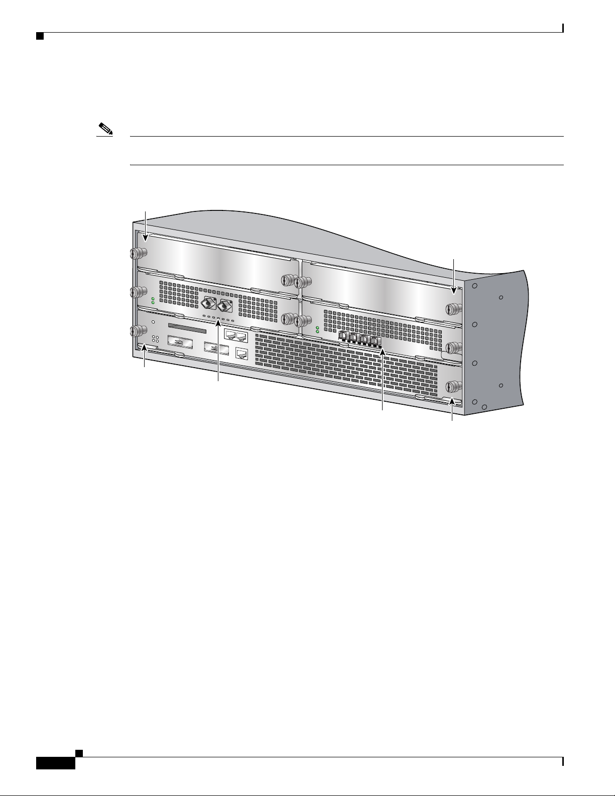
Note When a card is dual-wide (such as the NSE-100, NSE-150, or NPE-G100), the command-line interface
Chapter 3 Starting and Configuring
The line card and carrier card slots in the Cisco 7304 router are numbered slot 0 to slot 5. Slot 0 and slot
1 are reserved for the processing engine, NSE-100, NSE-150, or NPE-G100. Figure 3-1 shows the slot
numbering for a Cisco 7304 with an NSE-100 installed in slot 0.
(CLI) will reference the card in the left-side slot number.
Figure 3-1 Cisco 7304 Slot Numbering
Slot 4
Slot 5
9K-10C48
T
OIR
STATUS
1-PORT OC48 POS w/ SM
SR
X
R
X
9K
-4
0C
3/P
O
S
-M
M
OIR
OIR
STATUS
Slot 0
Slot 2
STATUS
4-PORT OC3 POS w/ MM
0
1
2
CARRIER/
ALARM
3
ACTIVE/
LOOPBACK
57905
Slot 3
Slot 1
The Media Access Control (MAC) or hardware address is a standardized data link layer address that is
required for certain network interface types. These addresses are not used by other devices in the
network; they are specific and unique to each port. The Cisco 7304 router uses a specific method to
assign and control the MAC addresses of its line cards. For a description of the MAC address, see the
“MAC Address” section on page 3-5.
You can identify which line cards are present with the show c7300 command.
Router> show c7300
Slot Card Type Status Insertion time
---- --------- ------ -------------0,1 NSE100 Active 1d17h ago
5 POS OC3 Active 1d17h ago
System is compliant with hardware configuration guidelines.
Network IO Interrupt Throttling:
throttle count=2, timer count=2
active=0, configured=1
netint usec=3999, netint mask usec=200
3-2
You can identify line card slots by using software commands. To display information about all line card
slots, use the show interfaces command. To display information about a specific line card slot, use the
show interfaces command with the line card type and slot number in the format show interfaces
Cisco 7304 Installation and Configuration Guide
78-13279-01 B0
Page 3

Chapter 3 Starting and Configuring
slot-number/interface-port number. If you abbreviate the command (sh int) and do not specify line card
type and slot number (or arguments), the system interprets the command as show interfaces and displays
the status of all line cards and ports.
The following example shows how the show interfaces command, used without arguments, displays
status information (including the physical line card number) for each line card in a Cisco 7304 router
with an NSE-100.
In the following example, most of the status information for each interface is omitted.
Router# show interfaces
FastEthernet0/0 is up, line protocol is up
Hardware is Mistral EOBC, address is 0060.2f86.0d20 (bia 0060.2f86.0d20)
Internet address is 10.0.0.0/0
MTU 1500 bytes, BW 100000 Kbit, DLY 100 usec,
reliability 255/255, txload 1/255, rxload 1/255
Encapsulation ARPA, loopback not set
Half-duplex, 100Mb/s, MII
ARP type: ARPA, ARP Timeout 04:00:00
Last input 00:00:00, output 00:00:02, output hang never
Last clearing of "show interface" counters 15:45:55
Input queue: 0/75/0/0 (size/max/drops/flushes); Total output drops: 0
Queueing strategy: fifo
Output queue :0/40 (size/max)
5 minute input rate 1000 bits/sec, 2 packets/sec
5 minute output rate 0 bits/sec, 0 packets/sec
193906 packets input, 15705972 bytes
Received 193776 broadcasts, 0 runts, 0 giants, 0 throttles
0 input errors, 0 CRC, 0 frame, 0 overrun, 0 ignored
0 watchdog
0 input packets with dribble condition detected
866 packets output, 76916 bytes, 0 underruns
0 output errors, 0 collisions, 0 interface resets
0 babbles, 0 late collision, 0 deferred
0 lost carrier, 0 no carrier
0 output buffer failures, 0 output buffers swapped out
GigabitEthernet0/0 is up, line protocol is up
Hardware is Pinnacle GE, address is 0060.2f86.0d00 (bia 0060.2f86.0d00)
Internet address is 10.0.0.0/0
MTU 1500 bytes, BW 1000000 Kbit, DLY 10 usec,
reliability 255/255, txload 1/255, rxload 1/255
Encapsulation ARPA, loopback not set
Full-duplex mode, link type is force-up, media type is unknown 25
output flow-control is unsupported, input flow-control is unsupported
ARP type: ARPA, ARP Timeout 04:00:00
Last input never, output 15:45:44, output hang never
Last clearing of "show interface" counters 15:46:04
Input queue: 0/75/0/0 (size/max/drops/flushes); Total output drops: 0
Queueing strategy: fifo
Output queue :0/40 (size/max)
5 minute input rate 0 bits/sec, 0 packets/sec
5 minute output rate 0 bits/sec, 0 packets/sec
0 packets input, 0 bytes, 0 no buffer
Received 0 broadcasts, 0 runts, 0 giants, 0 throttles
0 input errors, 0 CRC, 0 frame, 0 overrun, 0 ignored
0 watchdog, 0 multicast, 0 pause input
0 input packets with dribble condition detected
0 packets output, 0 bytes, 0 underruns
0 output errors, 0 collisions, 0 interface resets
0 babbles, 0 late collision, 0 deferred
0 lost carrier, 0 no carrier, 0 pause output
0 output buffer failures, 0 output buffers swapped out
GigabitEthernet0/1 is up, line protocol is up
Hardware is Pinnacle GE, address is 0060.2f86.0d01 (bia 0060.2f86.0d01)
Functional Overview
78-13279-01 B0
Cisco 7304 Installation and Configuration Guide
3-3
Page 4

Functional Overview
Chapter 3 Starting and Configuring
Internet address is 10.0.0.0/0
MTU 1500 bytes, BW 1000000 Kbit, DLY 10 usec,
reliability 255/255, txload 1/255, rxload 1/255
Encapsulation ARPA, loopback not set
Full-duplex mode, link type is force-up, media type is unknown 25
output flow-control is unsupported, input flow-control is unsupported
ARP type: ARPA, ARP Timeout 04:00:00
Last input never, output 15:45:49, output hang never
Last clearing of "show interface" counters 15:46:08
Input queue: 0/75/0/0 (size/max/drops/flushes); Total output drops: 0
Queueing strategy: fifo
Output queue :0/40 (size/max)
5 minute input rate 0 bits/sec, 0 packets/sec
5 minute output rate 0 bits/sec, 0 packets/sec
0 packets input, 0 bytes, 0 no buffer
Received 0 broadcasts, 0 runts, 0 giants, 0 throttles
0 input errors, 0 CRC, 0 frame, 0 overrun, 0 ignored
0 watchdog, 0 multicast, 0 pause input
0 input packets with dribble condition detected
0 packets output, 0 bytes, 0 underruns
0 output errors, 0 collisions, 0 interface resets
0 babbles, 0 late collision, 0 deferred
0 lost carrier, 0 no carrier, 0 pause output
0 output buffer failures, 0 output buffers swapped out
POS4/0 is up, line protocol is up
Hardware is Packet over Sonet
Internet address is 10.0.0.0/0
MTU 4470 bytes, BW 2488000 Kbit, DLY 100 usec,
reliability 255/255, txload 53/255, rxload 50/255
Encapsulation HDLC, crc 16, loopback not set
Keepalive not set
Scramble disabled
Last input 15:39:24, output 15:39:23, output hang never
Last clearing of "show interface" counters 15:46:20
Input queue: 0/75/0/0 (size/max/drops/flushes); Total output drops: 0
Queueing strategy: fifo
Output queue :0/40 (size/max)
5 minute input rate 492305000 bits/sec, 1538508 packets/sec
5 minute output rate 525842000 bits/sec, 43878 packets/sec
1201804187 packets input, 827532624 bytes, 0 no buffer
Received 0 broadcasts, 0 runts, 0 giants, 0 throttles
0 parity
0 input errors, 0 CRC, 0 frame, 0 overrun, 0 ignored, 0 abort
2486540100 packets output, 1100263868 bytes, 0 underruns
0 output errors, 0 applique, 0 interface resets
0 output buffer failures, 0 output buffers swapped out
0 carrier transitions
POS5/0 is up, line protocol is up
Hardware is Packet over Sonet
Internet address is 10.0.0.0/0
MTU 4470 bytes, BW 155520 Kbit, DLY 100 usec,
reliability 255/255, txload 1/255, rxload 1/255
Encapsulation HDLC, crc 16, loopback not set
Keepalive not set
Scramble disabled
Last input never, output 15:46:02, output hang never
Last clearing of "show interface" counters 15:46:22
Input queue: 0/75/0/0 (size/max/drops/flushes); Total output drops: 0
Queueing strategy: fifo
Output queue :0/40 (size/max)
5 minute input rate 0 bits/sec, 0 packets/sec
5 minute output rate 0 bits/sec, 0 packets/sec
3-4
(display text omitted)
Cisco 7304 Installation and Configuration Guide
78-13279-01 B0
Page 5

Chapter 3 Starting and Configuring
POS5/1 is up, line protocol is up
Hardware is Packet over Sonet
Internet address is 10.0.0.0/0
MTU 4470 bytes, BW 155520 Kbit, DLY 100 usec,
reliability 255/255, txload 1/255, rxload 1/255
Encapsulation HDLC, crc 16, loopback not set
Keepalive not set
Scramble disabled
Last input never, output never, output hang never
Last clearing of "show interface" counters 15:46:23
Input queue: 0/75/0/0 (size/max/drops/flushes); Total output drops: 0
Queueing strategy: fifo
Output queue :0/40 (size/max)
5 minute input rate 0 bits/sec, 0 packets/sec
5 minute output rate 0 bits/sec, 0 packets/sec
(display text omitted)
POS5/2 is administratively down, line protocol is down
Hardware is Packet over Sonet
MTU 4470 bytes, BW 155520 Kbit, DLY 100 usec,
reliability 255/255, txload 1/255, rxload 1/255
Encapsulation HDLC, crc 16, loopback not set
Keepalive set (10 sec)
Scramble disabled
Last input never, output never, output hang never
Last clearing of "show interface" counters 15:46:39
Input queue: 0/75/0/0 (size/max/drops/flushes); Total output drops: 0
Queueing strategy: fifo
Output queue :0/40 (size/max)
Functional Overview
MAC Address
(display text omitted)
POS5/3 is administratively down, line protocol is down
Hardware is Packet over Sonet
MTU 4470 bytes, BW 155520 Kbit, DLY 100 usec,
reliability 255/255, txload 1/255, rxload 1/255
Encapsulation HDLC, crc 16, loopback not set
Keepalive set (10 sec)
Scramble disabled
Last input never, output never, output hang never
Last clearing of "show interface" counters 15:46:42
Input queue: 0/75/0/0 (size/max/drops/flushes); Total output drops: 0
Queueing strategy: fifo
Output queue :0/40 (size/max)
(display text omitted)
For complete descriptions and instructions of the commands used to configure your Cisco 7304 router,
refer to the Cisco IOS Configuration Fundamentals Configuration Guide and Cisco IOS Configuration
Fundamentals Command Reference publications, which are available online, on the Documentation
CD-ROM, and in print.
All LAN interfaces (ports) require unique MAC addresses, also known as hardware addresses. Typically,
the MAC address of an interface is stored on a memory component that resides directly on the interface
circuitry; however, the OIR feature requires a different method. (For a description of OIR, see the
“Online Insertion and Removal” section on page 3-6.)
78-13279-01 B0
Cisco 7304 Installation and Configuration Guide
3-5
Page 6

Functional Overview
Using OIR you can remove a line card and replace it with another identically configured one. If the new
line card matches the line card you removed, the system immediately brings it online. In order to enable
OIR, an address allocator with unique MAC addresses is stored in an EEPROM on the midplane. Each
address is reserved for a specific port and slot in the router regardless of whether a line card resides in
that slot. You can remove a line card and insert it into another router without causing the MAC addresses
to move around the network or be assigned to multiple devices.
Note that if the MAC addresses were stored on each line card, OIR would not function because you could
never replace one line card with an identical one; the MAC addresses would always be different. Also,
each time a line card was replaced, other devices on the network would have to update their data
structures with the new address. If the other devices did not update quickly enough, the same MAC
address could appear in more than one device at the same time.
Note Storing the MAC addresses for every slot in one central location means the addresses stay with the
memory device on which they are stored.
Online Insertion and Removal
Chapter 3 Starting and Configuring
All line cards in the Cisco 7304 routers support online insertion and removal (OIR). The term “line
cards” include line cards, PCI port adapters, SPAs, MSCs, and the inactive and redundant processing
engine. This function allows you to install and replace line cards while the router is operating. This
provides a method that is seamless to end users on the network, maintains all routing information, and
preserves sessions.
You can remove line cards from the Cisco 7304 router without disrupting data flow by using the
hw-module slot slot-number stop | start command. The hw-module slot slot-number stop command
stops traffic, shuts down all line card interfaces, and deactivates the line card. The hw-module slot
slot-number start command restarts the line card and shuts off the OIR LED, putting the card back
online.
The following is a functional description of OIR for background information only; for specific
procedures for installing and replacing a line card in a Cisco 7304 router, refer to the online
configuration note for each line card, PCI port adapter, SPA, MSC, or (redundant) processing engine.
Each line card has a bus connector that connects it to the router. The connector has a set of tiered pins
that send specific signals to the system as they make contact with the line card. The system assesses the
signals it receives and the order in which it receives them to determine if a line card is being removed or
inserted into the system. From these signals, the system determines whether to reinitialize a new
interface or shut down a removed interface.
For example, when you insert a line card, the longest pins make contact with the line card first, and the
shortest pins make contact last. The system recognizes the signals and the sequence in which it receives
them.
When you remove or insert a line card in a Cisco 7304 router, the pins send signals to notify the system,
which then performs as follows:
3-6
1. Rapidly scans the system for configuration changes.
2. Initializes all newly inserted line cards, noting any removed interfaces.
3. Brings all previously configured interfaces on the line card back to the state they were in when they
were removed. Any newly inserted interface is put in the administratively shutdown state, as if it
was present (but not configured) at boot time. If a similar line card type is reinserted into a slot, its
ports are configured and brought online up to the port count of the original line card.
Cisco 7304 Installation and Configuration Guide
78-13279-01 B0
Page 7

Chapter 3 Starting and Configuring
Environmental Monitoring and Reporting Functions
Environmental monitoring and reporting functions are controlled by the processing engine and allow you
to maintain normal system operation by identifying and resolving adverse conditions prior to loss of
operation. The environmental monitoring functions constantly monitor the internal chassis air
temperature and DC supply voltages and currents. Each power supply monitors its own voltage and
temperature and shuts itself down if it detects a critical condition within the power supply. If conditions
reach shutdown thresholds, the system shuts down to avoid equipment damage from excessive heat. The
reporting functions periodically log the values of measured parameters so that you can retrieve them for
analysis later, and the reporting functions display warnings on the console if any of the monitored
parameters exceed defined thresholds.
Environmental Monitoring
The environmental monitoring functions use three sensors on the processing engine, one sensor on the
CPU daughter board, and the sensors on the line cards to monitor the temperature of the cooling air as
it moves through the chassis. The environmental monitoring functions also monitor power supply and
fan failure events and online insertion and removal (OIR) events.
If the air temperature exceeds a defined threshold, the system controller displays warning messages on
the console terminal, and if the temperature exceeds the shutdown threshold, the system controller shuts
down the system. The system stores the present parameter measurements for both temperature and DC
voltage in NVRAM so you can retrieve them later as a report of the last shutdown parameters.
In addition, the power supplies monitor internal power supply temperature and voltages. A power supply
is either within tolerance (normal) or out of tolerance (critical). If an internal power supply temperature
or voltage reaches a critical level, the power supply shuts down without any interaction with the system
processor.
Functional Overview
The environmental monitoring functions use the following levels of status conditions to monitor the
system:
• Normal—All monitored parameters are within normal tolerances.
• Warning—The system has exceeded a specified threshold. The system continues to operate, but
operator action is recommended to bring the system back to a normal state.
• Critical—An out-of-tolerance temperature or voltage condition exists. The system continues to
operate; however, the system is approaching shutdown. Immediate operator action is required.
• Shutdown—The processor has detected a temperature condition that could result in physical damage
to system components and has disabled DC power to all internal components. This condition
requires immediate operator action. All DC power remains disabled until you toggle the power
switch. Before any shutdown, the system logs the status of monitored parameters in NVRAM so you
can retrieve it later to help determine the cause of the problem.
• Power supply shutdown—The power supply detected an internal out-of-tolerance overvoltage,
overcurrent, or temperature condition and shut itself down. All DC power remains disabled until you
toggle the power switch.
Table 3-1 lists the typical temperature thresholds for the NSE-100, and Table 3-2 lists the DC power
thresholds for the normal, warning, and critical (power supply-monitored) levels.
78-13279-01 B0
Cisco 7304 Installation and Configuration Guide
3-7
Page 8

Functional Overview
Chapter 3 Starting and Configuring
Table 3-1 Typical Processor-Monitored Temperature Thresholds
Parameter High Warning High Critical Shutdown
NSE-100
Chassis inlet 119°F (48°C) 145°F (63°C) 154°F (68°C)
Chassis outlet 1 119°F (48°C) 145°F (63°C) 154°F (68°C)
Chassis outlet 2 119°F (48°C) 145°F (63°C) 154°F (68°C)
Table 3-2 Typical Power Supply-Monitored DC-Voltage Thresholds
Parameter Low Critical Low Warning High Warning High Critical
+3.45V +3.26V +3.34V +3.55V +3.63V
+5.15V +4.86V +4.99V +5.31V +5.43V
+12.15V +11.39V +11.67V +12.62V +12.91V
–11.95V –9.52V –10.73V –13.16V –14.38V
Reporting Functions
The Cisco 7304 router displays warning messages on the console if chassis interface-monitored
parameters exceed a desired threshold. You can also retrieve and display environmental status reports
with the show environment, show environment all, show environment last, and show environment
table commands. Parameters are measured and reporting functions are updated every 60 seconds. A brief
description of each of these commands follows.
Caution To prevent overheating the chassis, ensure that your system is drawing cool inlet air. Overtemperature
conditions can occur if the system is drawing in the exhaust air of other equipment. Ensure adequate
clearance around the sides of the chassis so that cooling air can flow through the chassis interior
unimpeded and exhaust air exits the chassis and is not drawn into the inlet vent of another device.
The show environment command displays reports of the current environmental system status. The
report displays parameters that are out of the normal values. No parameters are displayed if the system
status is normal. The example that follows shows the display for a system in which all monitored
parameters are within normal range:
Router# show environment
NSE board:
Line card slot 3:
Line card slot 4:
Line card slot 5:
Voltage information:
NSE board:
Line card slot 3:
Line card slot 4:
Line card slot 5:
All measured values are normal
3-8
Router# show environment all
Power Supplies:
Power supply 1 is AC power supply. Unit is on.
Power supply 2 is empty.
Cisco 7304 Installation and Configuration Guide
78-13279-01 B0
Page 9

Chapter 3 Starting and Configuring
Fans:
Fan 1 is on.
Fan 2 is on.
Temperature readings:
NSE board:
nse outlet measured at 34C/93F
nse inlet measured at 30C/86F
nse hotspot measured at 38C/100F
nse db measured at 32C/89F
Line card slot 4:
pos_oc48 measured at 41C/105F
Line card slot 5:
pos_oc48 measured at 41C/105F
Voltage readings:
NSE board:
nse outlet 1.8 V measured at 1692 mV
nse outlet 2.5 V measured at 2483 mV
nse outlet 3.3 V measured at 3285 mV
nse outlet 5 V measured at 5044 mV
nse outlet 12 V measured at 11625 mV
nse inlet 1.8 V measured at 1776 mV
nse inlet 3.3 V measured at 3371 mV
nse hotspot 1.8 V measured at 1748 mV
nse db 1.65 V measured at 1635 mV
nse db 1.8 V measured at 1790 mV
Line card slot 4:
pos_oc48 1.8 V measured at 1790 mV
pos_oc48 2.5 V measured at 2483 mV
pos_oc48 3.3 V measured at 3285 mV
pos_oc48 5 V measured at 5044 mV
pos_oc48 12 V measured at 11750 mV
Line card slot 5:
pos_oc48 1.8 V measured at 1790 mV
pos_oc48 2.5 V measured at 2483 mV
pos_oc48 3.3 V measured at 3285 mV
pos_oc48 5 V measured at 5044 mV
pos_oc48 12 V measured at 11750 mV
Envm stats saved 7 time(s) since reload.
Functional Overview
78-13279-01 B0
If the environmental status is not normal, the system reports the worst-case status level. Following is a
sample overvoltage warning:
Router# show environment
Warning: +3.45 V measured at +3.83 V
The show environment last command retrieves and displays the NVRAM log, which shows the reason
for the last system shutdown (if the shutdown was related to voltage or temperature) and the
environmental status at that time. Air temperature is measured and displayed, and the DC voltage
supplied by the power supply is also displayed.
Following is sample output of the show environment last command:
Router# show environment last
Temperature information:
NSE board:
nse outlet previously measured at 34C/93F
nse inlet previously measured at 30C/86F
nse hotspot previously measured at 37C/98F
nse db previously measured at 33C/91F
Line card slot 3:
pos_oc48 previously measured at 39C/102F
Line card slot 4:
pos_oc48 previously measured at 39C/102F
Cisco 7304 Installation and Configuration Guide
3-9
Page 10

Functional Overview
Chapter 3 Starting and Configuring
Line card slot 5:
pos_oc48 previously measured at 39C/102F
Voltage information:
NSE board:
nse outlet 1.8 V previously measured at 1.692 V
nse outlet 2.5 V previously measured at 2.483 V
nse outlet 3.3 V previously measured at 3.285 V
nse outlet 5 V previously measured at 5.044 V
nse outlet 12 V previously measured at 11.625 V
nse inlet 1.8 V previously measured at 1.776 V
nse inlet 3.3 V previously measured at 3.371 V
nse hotspot 1.8 V previously measured at 1.748 V
nse db 1.65 V previously measured at 1.635 V
nse db 1.8 V previously measured at 1.790 V
Line card slot 3:
pos_oc48 1.8 V previously measured at 1.790 V
pos_oc48 2.5 V previously measured at 2.496 V
pos_oc48 3.3 V previously measured at 3.285 V
pos_oc48 5 V previously measured at 5.044 V
pos_oc48 12 V previously measured at 11.750 V
Line card slot 4:
pos_oc48 1.8 V previously measured at 1.790 V
pos_oc48 2.5 V previously measured at 2.496 V
pos_oc48 3.3 V previously measured at 3.285 V
pos_oc48 5 V previously measured at 5.044 V
pos_oc48 12 V previously measured at 11.750 V
Line card slot 5:
pos_oc48 1.8 V previously measured at 1.790 V
pos_oc48 2.5 V previously measured at 2.496 V
pos_oc48 3.3 V previously measured at 3.285 V
pos_oc48 5 V previously measured at 5.044 V
pos_oc48 12 V previously measured at 11.750 V
Last shutdown reason: power supply shutdown
The show environment table command displays the temperature and voltage thresholds for each
temperature sensor and for each monitored status level. These thresholds are related to those listed in
Table 3-1 and Tab le 3 -2. The display also lists the shutdown threshold for the system.
Following is sample output of the show environment table command for a Cisco 7304 router that has
an installed NSE-100:
Router# show environment table
Temperature tables:
NSE board:
Sample Point HighWarning HighCritical HighShutdown
nse outlet 48C/118F 63C/145F 68C/154F
nse inlet 48C/118F 63C/145F 68C/154F
nse hotspot 48C/118F 63C/145F 68C/154F
nse db 48C/118F 63C/145F 68C/154F
Line card slot 3:
Sample Point HighWarning HighCritical HighShutdown
pos_oc48 48C/118F 63C/145F 68C/154F
Line card slot 4:
Sample Point HighWarning HighCritical HighShutdown
pos_oc48 48C/118F 63C/145F 68C/154F
Line card slot 5:
Sample Point HighWarning HighCritical HighShutdown
pos_oc48 48C/118F 63C/145F 68C/154F
Voltage tables:
NSE board:
Sample Point LowShut LowCrit LowWarn HighWarn HighCrit HighShut
nse outlet 1.8 V 1.620 V 1.710 V 1.728 V 1.872 V 1.890 V 1.980 V
nse outlet 2.5 V 2.275 V 2.375 V 2.400 V 2.600 V 2.625 V 2.725 V
nse outlet 3.3 V 3.003 V 3.152 V 3.185 V 3.415 V 3.448 V 3.597 V
3-10
Cisco 7304 Installation and Configuration Guide
78-13279-01 B0
Page 11

Chapter 3 Starting and Configuring
nse outlet 5 V 4.500 V 4.750 V 4.800 V 5.200 V 5.250 V 5.500 V
nse outlet 12 V 9.960 V 10.440 V 10.800 V 13.200 V 13.560 V 14.040 V
nse inlet 1.8 V 1.620 V 1.710 V 1.728 V 1.872 V 1.890 V 1.980 V
nse inlet 3.3 V 3.003 V 3.152 V 3.185 V 3.415 V 3.448 V 3.597 V
nse hotspot 1.8 V 1.620 V 1.710 V 1.728 V 1.872 V 1.890 V 1.980 V
nse db 1.65 V 1.485 V 1.601 V 1.604 V 1.696 V 1.699 V 1.815 V
nse db 1.8 V 1.620 V 1.710 V 1.728 V 1.872 V 1.890 V 1.980 V
Line card slot 3:
Sample Point LowShut LowCrit LowWarn HighWarn HighCrit HighShut
pos_oc48 1.8 V 1.620 V 1.710 V 1.728 V 1.872 V 1.890 V 1.980 V
pos_oc48 2.5 V 2.250 V 2.375 V 2.400 V 2.600 V 2.625 V 2.750 V
pos_oc48 3.3 V 2.970 V 3.135 V 3.168 V 3.432 V 3.465 V 3.630 V
pos_oc48 5 V 4.500 V 4.750 V 4.800 V 5.200 V 5.250 V 5.500 V
pos_oc48 12 V 9.960 V 10.440 V 10.800 V 13.200 V 13.560 V 14.040 V
Line card slot 4:
Sample Point LowShut LowCrit LowWarn HighWarn HighCrit HighShut
pos_oc48 1.8 V 1.620 V 1.710 V 1.728 V 1.872 V 1.890 V 1.980 V
pos_oc48 2.5 V 2.250 V 2.375 V 2.400 V 2.600 V 2.625 V 2.750 V
pos_oc48 3.3 V 2.970 V 3.135 V 3.168 V 3.432 V 3.465 V 3.630 V
pos_oc48 5 V 4.500 V 4.750 V 4.800 V 5.200 V 5.250 V 5.500 V
pos_oc48 12 V 9.960 V 10.440 V 10.800 V 13.200 V 13.560 V 14.040 V
Line card slot 5:
Sample Point LowShut LowCrit LowWarn HighWarn HighCrit HighShut
pos_oc48 1.8 V 1.620 V 1.710 V 1.728 V 1.872 V 1.890 V 1.980 V
pos_oc48 2.5 V 2.250 V 2.375 V 2.400 V 2.600 V 2.625 V 2.750 V
pos_oc48 3.3 V 2.970 V 3.135 V 3.168 V 3.432 V 3.465 V 3.630 V
pos_oc48 5 V 4.500 V 4.750 V 4.800 V 5.200 V 5.250 V 5.500 V
pos_oc48 12 V 9.960 V 10.440 V 10.800 V 13.200 V 13.560 V 14.040 V
Functional Overview
Note Temperature and voltage ranges and values are subject to change.
The show environment all command displays an extended report that includes temperature readings and
voltage readings. The show environment all command also displays a report showing which power
supply slots are occupied and which are empty.
Following is sample output of the show environment all command:
Router# show environment all
Power Supplies:
Power supply 1 is AC power supply. Unit is on.
Power supply 2 is empty.
Fans:
Fan 1 is on.
Fan 2 is on.
Temperature readings:
NSE board:
nse outlet measured at 34C/93F
nse inlet measured at 30C/86F
nse hotspot measured at 37C/98F
nse db measured at 33C/91F
Line card slot 3:
pos_oc48 measured at 39C/102F
Line card slot 4:
pos_oc48 measured at 39C/102F
Line card slot 5:
pos_oc48 measured at 39C/102F
Voltage readings:
NSE board:
nse outlet 1.8 V measured at 1.770 V
nse outlet 2.5 V measured at 2.483 V
nse outlet 3.3 V measured at 3.285 V
78-13279-01 B0
Cisco 7304 Installation and Configuration Guide
3-11
Page 12

Checking Conditions Prior to System Startup
nse outlet 5 V measured at 5.044 V
nse outlet 12 V measured at 11.625 V
nse inlet 1.8 V measured at 1.776 V
nse inlet 3.3 V measured at 3.371 V
nse hotspot 1.8 V measured at 1.748 V
nse db 1.65 V measured at 1.635 V
nse db 1.8 V measured at 1.790 V
Line card slot 3:
pos_oc48 1.8 V measured at 1.790 V
pos_oc48 2.5 V measured at 2.496 V
pos_oc48 3.3 V measured at 3.285 V
pos_oc48 5 V measured at 5.044 V
pos_oc48 12 V measured at 11.750 V
Line card slot 4:
pos_oc48 1.8 V measured at 1.790 V
pos_oc48 2.5 V measured at 2.496 V
pos_oc48 3.3 V measured at 3.285 V
pos_oc48 5 V measured at 5.044 V
pos_oc48 12 V measured at 11.750 V
Line card slot 5:
pos_oc48 1.8 V measured at 1.790 V
pos_oc48 2.5 V measured at 2.496 V
pos_oc48 3.3 V measured at 3.285 V
pos_oc48 5 V measured at 5.044 V
pos_oc48 12 V measured at 11.750 V
Envm stats saved 1 time(s) since reload
Chapter 3 Starting and Configuring
Fan Failures
Each power supply has a fan module. The environmental monitoring system treats each module as a
power supply and a fan at the same location. The system requires two fans. The Cisco 7304 can either
have two power supplies if power supply redundancy is required or one power supply and one fan
module.
When the system power is on, both fans should be operational. The system continues to operate if a fan
fails; however, if the air temperature exceeds a defined threshold, the system controller displays warning
messages on the console terminal, and if the temperature exceeds the shutdown threshold, the system
controller shuts down the system.
If the system does shut down because the temperature exceeded the shutdown threshold, the system
displays the following message on the console screen and in the environment display when the system
restarts:
Queued messages:
%ENVM-1-SHUTDOWN: Environmental Monitor initiated shutdown
For complete descriptions and instructions for the environmental monitor commands, refer to the
Cisco IOS Configuration Fundamentals Configuration Guide and Cisco IOS Configuration
Fundamentals Command Reference publications, which are available online, on the Documentation
CD-ROM, and in print.
Checking Conditions Prior to System Startup
3-12
Check the following conditions before you start your router:
• The line cards are inserted in their slots and the line card locking levers are in the locked position.
• The network interface cables are connected to the line cards.
Cisco 7304 Installation and Configuration Guide
78-13279-01 B0
Page 13

Chapter 3 Starting and Configuring
Starting the System and Observing Initial Conditions
• A CompactFlash Disk is installed.
• The console terminal is turned on.
You are now ready to start your router. Proceed to the section “Starting the System and Observing Initial
Conditions.”
Starting the System and Observing Initial Conditions
After installing your Cisco 7304 router and connecting cables, start the router as follows:
Step 1 Make sure the power cables are connected to the router.
Step 2 Plug the AC power supply cable into the AC power source, or make sure the circuit breaker at the DC
panel is turned to the on position. Turn the power switch on.
Step 3 Listen for the fans; you should immediately hear them operating.
Step 4 During the boot process, observe the system LEDs. The LEDs on the line card go on and off in irregular
sequence. They may go on, go out, and go on again for a short time.
Step 5 Observe the initialization process. When the system boot is complete (a few seconds), the processor
begins to initialize the line card and the I/O subsystem. During this initialization, the LEDs on the line
card probably will flash on and off.
The STATUS LED on each line card goes on when initialization is completed, and the console screen
displays a script and system banner similar to the following:
Cisco Internetwork Operating System Software
IOS (tm) 7300 Software (C7300-JS-M), Version 12.1(9), CISCO RELEASED VERSION
Copyright (c) 1986-2001 by cisco Systems, Inc.
Compiled Tue 17-Jul-01 01:51 by biff
Image text-base:0x40008970, data-base:0x40BF8000
Step 6 When you start up the router for the first time, the system automatically enters the setup command
facility, which determines which line cards are installed and prompts you for configuration information
for each one. On the console terminal, after the system displays the system banner and hardware
configuration, you will see the following System Configuration Dialog prompt:
--- System Configuration Dialog ---
At any point you may enter a questions mark ‘?’ for help.
Use ctrl-c to abort configuration dialog at any prompt.
Default settings are in square brackets ‘[]’.
continue with configuration dialog? [yes]:
You have the option of proceeding with the setup facility to configure the interfaces, or exiting from
setup and using configuration commands to configure global (system-wide) and interface-specific
parameters. You do not have to configure the interfaces immediately; however, you cannot enable the
interfaces or connect them to any networks until you have configured them.
Many of the line card LEDs do not go on until you have configured the interfaces. To verify correct
operation of each interface, complete the first-time startup procedures and configuration, and then refer
to the configuration note for each line card for LED descriptions and to check the status of the interfaces.
78-13279-01 B0
Cisco 7304 Installation and Configuration Guide
3-13
Page 14

Configuring a Cisco 7304 Router
If the system does not complete each of the steps in the startup procedure, proceed to Chapter 4,
“Troubleshooting,” for troubleshooting recommendations and procedures.
Configuring a Cisco 7304 Router
You can configure your Cisco 7304 router using one of the procedures described in the following
sections:
• Performing a Basic Configuration Using AutoInstall, page 3-14
• Performing a Basic Configuration Using the Setup Facility, page 3-15
Follow the procedure that best fits the needs of your network configuration.
Note You need to acquire the correct network addresses from your system administrator or consult your
network plan to determine correct addresses before you can complete the router configuration.
Before continuing the configuration process, check the current state of the router by entering the show
version command. The show version command displays the release of Cisco IOS software that is
available on the router. Sample output of the show version command appears in the “Viewing Your
System Configuration” section on page 3-23.
Chapter 3 Starting and Configuring
Performing a Basic Configuration Using AutoInstall
The AutoInstall process is designed to configure the Cisco 7304 router automatically after connection
to your WAN. For AutoInstall to work properly, a TCP/IP host on your network must be preconfigured
to provide the required configuration files. The TCP/IP host may exist anywhere on the network as long
as the following two conditions are maintained:
1. The host must be on the remote side of the router synchronous serial connection to the WAN.
2. User Datagram Protocol (UDP) broadcasts to and from the router and the TCP/IP host are enabled.
This functionality is coordinated by your system administrator at the site where the TCP/IP host is
located. You should not use AutoInstall unless the required files are available on the TCP/IP host. Refer
to the publications Cisco IOS Configuration Fundamentals Configuration Guide and Cisco IOS
Configuration Fundamentals Command Reference for information about how AutoInstall works.
Complete the following steps to prepare your Cisco 7304 router for the AutoInstall process:
Step 1 Plug the AC power supply cable into the AC power source. Turn the power switch on.
The router loads the operating system image from Flash memory. If the remote end of the WAN
connection is connected and properly configured, the AutoInstall process begins.
Once the AutoInstall process is completed, use the copy running-config startup-config command to
write the configuration data to the router’s nonvolatile random-access memory (NVRAM). Perform the
following step to complete this task.
Step 2 At the # prompt, enter the following command:
Hostname# copy running-config startup-config
3-14
Cisco 7304 Installation and Configuration Guide
78-13279-01 B0
Page 15

Chapter 3 Starting and Configuring
Note Completing Step 2 saves the configuration settings that the AutoInstall process saved to NVRAM. If you
fail to do this, your configuration will be lost the next time you reload the router.
Performing a Basic Configuration Using the Setup Facility
Note You can run the setup facility any time you are at the enable prompt (#) by entering the setup command.
If the router does not have a configuration stored in NVRAM, the router attempts to run AutoInstall at
startup. The router may take several minutes to determine that AutoInstall is not set up to a remote
TCP/IP host. Once the router determines that AutoInstall is not configured, it defaults to the setup
facility.
Configuring Global Parameters
When you first start the setup program, you must configure the global parameters. These parameters are
used for controlling system-wide settings. Complete the following steps to enter the global parameters:
Configuring a Cisco 7304 Router
Step 1 Connect a console terminal to the console port, and then boot the router.
The system boots from Flash memory. The following information appears after about 30 seconds. When
you see this information, you have successfully booted your router:
Restricted Rights Legend
Use, duplication, or disclosure by the Government is
subject to restrictions as set forth in subparagraph
(c) of the Commercial Computer Software - Restricted
Rights clause at FAR sec. 52.227-19 and subparagraph
(c) (1) (ii) of the Rights in Technical Data and Computer
Software clause at DFARS sec. 252.227-7013.
cisco Systems, Inc.
170 West Tasman Drive
San Jose, California 95134-1706
Cisco Internetwork Operating System Software
IOS (tm) 7300 Software (C7300-JS-M), Version 12.1(9), CISCO RELEASED VERSION
Copyright (c) 1986-2001 by cisco Systems, Inc.
Compiled Tue 17-Jul-01 01:51 by biff
Image text-base:0x40008970, data-base:0x40BF8000
Downloading default microcode:system:pxf/ucode1
.Successfully downloaded the production microcode.
updating timeout values directly
Currently running ROMMON from OTP ROM
cisco 7300 (NSE100) processor (revision B) with 114688K/16384K bytes of memory.
Processor board ID
R7000 CPU at 350Mhz, Implementation 39, Rev 3.2, 256KB L2, 1024KB L3 Cache
4 slot midplane, Version 65.48
78-13279-01 B0
Last reset from watchdog nmi
X.25 software, Version 3.0.0.
PXF processor tmc0 is running.
Cisco 7304 Installation and Configuration Guide
3-15
Page 16

Configuring a Cisco 7304 Router
PXF processor tmc1 is running.
1 FastEthernet/IEEE 802.3 interface(s)
2 Gigabit Ethernet/IEEE 802.3 interface(s)
9 Packet over SONET network interface(s)
509K bytes of non-volatile configuration memory.
16064K bytes of ATA compact flash disk at bootdisk (Sector size 512 bytes).
31369K bytes of ATA compact flash disk at disk 0 (Sector size 512 bytes).
Press RETURN to get started!
Note The first two sections of the configuration script (the banner and the installed hardware) appear
--- System Configuration Dialog --At any point you may enter a question mark '?' for help.
Use ctrl-c to abort configuration dialog at any prompt.
Default settings are in square brackets '[]'.
Step 2 When asked if you want to enter the initial configuration dialog and see the current interface summary,
enter yes or press Return:
Would you like to enter the initial configuration dialog? [yes/no]:
Chapter 3 Starting and Configuring
only at initial system startup. On subsequent uses of the setup facility, the script begins with a
System Configuration Dialog as shown in the following example.
First, would you like to see the current interface summary? [yes]:
In the following example, the summary shows a Cisco 7304 router at first-time startup; that is, nothing
is configured.
Any interface listed with OK? value "NO" does not have a valid configuration
Interface IP-Address OK? Method Status Protocol
GigabitEthernet0/0 unassigned NO unset down down
GigabitEthernet0/1 unassigned NO unset down down
FastEthernet0/0 unassigned NO unset down down
Step 3 Choose which protocols to support on your interfaces. For Internet Protocol (IP)-only installations, you
can accept the default values for most of the questions. A typical configuration using IP, IPX, and
AppleTalk follows and continues through Step 8:
Configuring global parameters:
Enter host name [Router]:
Step 4 Enter enable secret, enable, and virtual terminal passwords:
The enable secret password is a one-way cryptographic secret
password used instead of the enable password when it exists.
The enable secret password is a one-way cryptographic secret
password used instead of the enable password when it exists.
Enter enable secret: barney
3-16
Cisco 7304 Installation and Configuration Guide
78-13279-01 B0
Page 17

Chapter 3 Starting and Configuring
The enable password is used when there is no enable secret
password and when using older software and some boot images.
Enter enable password: betty
Enter virtual terminal password: fred
Step 5 The Simple Network Management Protocol (SNMP) is the most widely supported open standard for
network management. It provides a means to access and set configuration and run-time parameters of
routers and communication servers. SNMP defines a set of functions that can be used to monitor and
control network elements.
Enter yes or press Return to accept SNMP management; enter no to refuse it:
Configure SNMP Network Management? [yes]:
Community string [public]:
Step 6 For the following queries, do not enable VINES, LAT, DECnet, CLNS, bridging, XNS, or Apollo:
Configure Vines? [no]:
Configure LAT? [no]:
Configure DECnet? [no]:
Configure CLNS? [no]:
Configure bridging? [no]:
Configure XNS? [no]:
Configure Apollo? [no]:
Configuring a Cisco 7304 Router
Step 7 For the following queries, enable routing on AppleTalk and IPX:
Configure AppleTalk? [no]: yes
Multizone networks? [no]: yes
Configure IPX? [no]: yes
Step 8 In most cases you use IP routing. If you are using IP routing, you must also select an interior routing
protocol. You can specify only one of two interior routing protocols to operate on your system using the
setup facility: Interior Gateway Routing Protocol (IGRP) or Routing Information Protocol (RIP).
To configure IP routing, enter yes (the default) or press Return, and then select an interior routing
protocol:
Configure IP? [yes]:
Configure IGRP routing? [yes]:
Your IGRP autonomous system number [1]: 15
The following sample display includes a continuous listing of all configuration parameters selected in
Step 3 through Step 8. Only IP, IPX, and AppleTalk are the selected protocols for this example.
Configuring global parameters:
Enter host name [Router]: router
The enable secret is a one-way cryptographic secret used
instead of the enable password when it exists.
Enter enable secret: barney
78-13279-01 B0
The enable password is used when there is no enable secret
and when using older software and some boot images.
Enter enable password: betty
Enter virtual terminal password: fred
Configure SNMP Network Management? [yes]:
Community string [public]:
Configure Vines? [no]:
Cisco 7304 Installation and Configuration Guide
3-17
Page 18

Configuring a Cisco 7304 Router
Configure LAT? [no]:
Configure AppleTalk? [no]: yes
Multizone networks? [no]: yes
Configure DECnet? [no]:
Configure IP? [yes]:
Configure IGRP routing? [yes]:
Your IGRP autonomous system number [1]: 15
Configure RIP routing? [no]:
Configure CLNS? [no]: n
Configure bridging? [no]:
Configure IPX? [no]: yes
Configure XNS? [no]:
Configure Apollo? [no]:
Step 9 Save your settings to NVRAM. (See the “Saving the Running Configuration to NVRAM” section on
page 3-19.) If you do not save the configuration settings that you created in the router using
configuration mode and the setup facility, your configuration will be lost the next time you reload the
router.
Configuring the Fast Ethernet Interface
Chapter 3 Starting and Configuring
Debugging
Configure the speed and duplex transmission mode to appropriately match the new interface
characteristics. Changing the speed and duplex of a Cisco 7304 router Fast Ethernet interface is done
using the speed and duplex interface commands.
Note These commands are only applicable when using the RJ-45 media.
speed { 10 | 100 | auto }
duplex { full | half | auto }
The following speed/duplex settings are supported.
Media Type Speed Duplex
------------------------------------------------------RJ45 10, 100, auto full, half, auto
GBIC ignored (1000) ignored (full)(By default on this interface)
-------------------------------------------------------
When using the GBIC media, there is also the additional negotiation auto command, which is used to
enable the IEEE 801.1z Gigabit Ethernet (1000 Mbps) autonegotiation protocol.
Cisco IOS provides two commands to provide information on your interfaces: show interface
GigabitEthernet 0/X (where X is either 0 or 1) and show controllers GigabitEthernet 0/X (where X
is either 0 or 1).
The output of the show interface command is useful for determining the current operating mode of the
interface (speed/duplex/media-type) and the current interface statistics.
The output of the show controller command displays more information specific to the Cisco 7304 router
Gigabit Ethernet interface. For example, it shows the detected link status, speed, and duplex, and also
determines the current status of autonegotiation and the link partners’ abilities (if it is an
autonegotiation-capable interface). (Speed and duplex are always full duplex, 1000-Mbps.)
3-18
Cisco 7304 Installation and Configuration Guide
78-13279-01 B0
Page 19

Chapter 3 Starting and Configuring
The show controller command also displays the current operating state of the driver and the Ethernet
controller hardware. The show controller command is a very powerful debugging aid, especially for
Cisco engineers should you need help in debugging a problem. If you have any problems with your
Gigabit Ethernet interfaces, you will need to provide this information to Cisco for analysis.
Resetting the Interface
Should you have a problem with your interface and you want to try and reset it, use the command:
clear interface GigabitEthernet 0/X (where X is either 0 or 1)
Clearing Counters
Interface counters may be cleared (reset) by using the command:
clear counters GigabitEthernet 0/X (where X is either 0 or 1)
Note Using this command will not reset the interface.
Configuring a Cisco 7304 Router
Configuring Line Card Interfaces
Following are the steps for configuring interfaces to allow communication over a LAN or WAN. To
configure the interface parameters, you need your interface network addresses and subnet mask
information. Consult with your network administrator for this information.
Step 1 Enter the config terminal command at the enable prompt to enter configuration mode from the terminal:
Router# config terminal
Enter configuration commands, one per line. End with CNTL/Z.
Router(config)#
At the Router(config)# prompt, enter the interface type slot/port command to enter the interface
configuration mode:
Router(config)# interface pos slot/port
In either configuration mode, you can now enter any changes to the configuration. Press Ctrl-Z (hold
down the Control key while you press Z) or enter end to exit configuration mode and return to the EXEC
command interpreter.
Step 2 Save your settings to NVRAM. (See the “Saving the Running Configuration to NVRAM” section on
page 3-19.) If you do not save the configuration settings that you created in the router using
configuration mode and the setup facility, your configuration will be lost the next time you reload the
router.
Your router is now minimally configured and will boot with the configuration you have entered. To see
a list of the configuration commands available to you, enter ? at the prompt while in configuration mode.
Saving the Running Configuration to NVRAM
To store the configuration or changes to your startup configuration in NVRAM, enter the copy
running-config startup-config command at the
78-13279-01 B0
Router# prompt:
Cisco 7304 Installation and Configuration Guide
3-19
Page 20

Performing Other Configuration Tasks
Router# copy running-config startup-config
Using this command saves the configuration settings that you created in the router using configuration
mode and the setup facility. If you fail to do this, your configuration will be lost the next time you reload
the router.
Checking the Running Configuration Settings
To check the value of the settings you have entered, enter the show running-config command at the
Router#
Router# show running-config
To review changes you make to the configuration, use the EXEC mode show startup-config command
to display the information stored in NVRAM.
prompt:
Performing Other Configuration Tasks
Chapter 3 Starting and Configuring
To make advanced configuration changes after you establish the basic startup configuration for your
router, refer to the modular configuration and modular command reference publications in the Cisco IOS
software configuration documentation set that corresponds to the software release installed on your
Cisco hardware. These publications contain additional information on using the configure command.
The configuration publications also provide information about the following tasks:
• Understanding and working with the user interface on your router
• Booting and rebooting the router
• Setting the configuration register
• Loading configuration files or system images using remote copy protocol (rcp) or Trivial File
Transfer Protocol (TFTP)
• Reloading the operating system
Replacing or Recovering a Lost Password
This section describes how to recover a lost enable or console login password, and how to replace a lost
enable secret password on your Cisco 7304 router.
Note It is possible to recover the enable or console login password. The enable secret password is encrypted,
however, and must be replaced with a new enable secret password.
Overview of the Password Recovery Procedure
Following is an overview of the steps in the password recovery procedure:
Step 1 If you can log in to the router, enter the show version command to determine the existing configuration
register value.
Cisco 7304 Installation and Configuration Guide
3-20
78-13279-01 B0
Page 21

Chapter 3 Starting and Configuring
Step 2 Press the Break key to get to the bootstrap program prompt (ROM monitor). You might need to reload
the system image by power cycling the router.
Step 3 Change the configuration register so the following functions are enabled:
a. Break
b. Ignore startup configuration
c. Boot from Flash memory
Note The key to recovering a lost password is to set the configuration register bit 6 (0x0040) so
Note When powering off the router, wait a minimum of 30 seconds before power it on or off again.
Step 4 Power cycle the router by turning power off and then back on.
Step 5 Log in to the router and enter the privileged EXEC mode.
Step 6 Enter the show startup-config command to display the passwords.
Step 7 Recover or replace the displayed passwords.
Replacing or Recovering a Lost Password
that the startup configuration (usually in NVRAM) is ignored. This allows you to log in
without using a password and to display the startup configuration passwords.
Step 8 Change the configuration register back to its original setting.
Note To recover a lost password if the Break function is disabled on the router, you must have physical access
to the router.
Details of the Password Recovery Procedure
Complete the following steps to recover or replace a lost enable, enable secret, or console login
password:
Step 1 Attach an ASCII terminal to the console port on your router.
Step 2 Configure the terminal to operate at 9600 baud, 8 data bits, no parity, and 2 stop bits (9600 8N2).
Step 3 If you can log in to the router as a nonprivileged user, enter the show version command to display the
existing configuration register value. Note the value for use later and proceed to Step 6. If you cannot
log in to the router at all, go to the next step.
Note When powering off the router, wait a minimum of 30 seconds before power it on or off again.
78-13279-01 B0
Step 4 Press the Break key or send a Break from the console terminal. If Break is enabled, the router enters the
ROM monitor, indicated by the ROM monitor prompt (
rommon1>). Proceed to Step 6. If Break is disabled,
power cycle the router (turn the router off or unplug the power cord, and then restore power). Then
proceed to Step 5.
Cisco 7304 Installation and Configuration Guide
3-21
Page 22

Replacing or Recovering a Lost Password
Step 5 Within 60 seconds of restoring the power to the router, press the Break key or send a Break. This action
causes the router to enter the ROM monitor and display the ROM monitor prompt (
Step 6 Set the configuration register using the configuration register utility; enter the confreg command at the
ROM monitor prompt as follows:
rommon1> confreg
Step 7 Answer yes to the enable “ignore system config info?” question, and note the current configuration
register settings.
Step 8 Initialize the router by entering the reset command as follows:
rommon2> reset
The router initializes, the configuration register is set to 0x142, and the router boots the system image
from Flash memory and enters the System Configuration Dialog as follows:
--- System Configuration Dialog --
Step 9 Enter no in response to the System Configuration Dialog prompts until the following message is
displayed:
Press RETURN to get started!
Step 10 Press Return. The user EXEC prompt is displayed as follows:
Router>
Step 11 Enter the enable command to enter privileged EXEC mode. Then enter the show startup-config
command to display the passwords in the configuration file as follows:
Router# show startup-config
Step 12 Scan the configuration file display looking for the passwords (the enable passwords are usually near the
beginning of the file, and the console login or user EXEC password is near the end). The passwords
displayed look something like this:
enable secret 5 $1$ORPP$s9syZt4uKn3SnpuLDrhuei
enable password 23skiddoo
.
.
line con 0
password onramp
The enable secret password is encrypted and cannot be recovered; it must be replaced. The enable and
console login passwords may be encrypted or clear text. Proceed to the next step to replace an enable
secret, console login, or enable password. If there is no enable secret password, note the enable and
console login passwords, if they are not encrypted, and proceed to Step 17.
Chapter 3 Starting and Configuring
rommon1>).
3-22
Caution Do not execute the next step unless you have determined you must change or replace the enable, enable
secret, or console login passwords. Failure to follow the steps as shown might cause you to erase your
router configuration.
Step 13 Enter the copy startup-config running config command to load the startup configuration file into
running memory. This action allows you to modify or replace passwords in the configuration.
Step 14 Enter the privileged EXEC command configure terminal to enter configuration mode:
Hostname# configure terminal
Step 15 Change all three passwords using the following commands:
Cisco 7304 Installation and Configuration Guide
78-13279-01 B0
Page 23

Chapter 3 Starting and Configuring
Hostname(config)# enable secret newpassword1
Hostname(config)#
Hostname(config-line)# password newpassword2
Change only the passwords necessary for your configuration. You can remove individual passwords by
using the no form of the above commands. For example, entering the no enable secret command
removes the enable secret password.
Step 16 You must configure all interfaces to be not administratively shut down as follows:
Hostname(config)# interface fastethernet 0/0
Hostname(config-int)#
Enter the equivalent commands for all interfaces that were originally configured. If you omit this step,
all interfaces are administratively shut down and unavailable when the router is restarted.
Step 17 Use the config-register command to set the configuration register to the original value noted in Step 3
or Step 8, or to the factory default value 0x2102 as follows:
Hostname(config)# config-register 0x2102
Step 18 Press Ctrl-Z (hold down the Control key while you press Z) or enter end to exit configuration mode
and return to the EXEC command interpreter.
Viewing Your System Configuration
line con 0
no shutdown
Caution Do not execute the next step unless you have changed or replaced a password. If you skipped Step 13
through Step 16, skip to Step 20. Failure to observe this caution causes you to erase your router
configuration file.
Step 19 Enter the copy running-config startup-config command to save the new configuration to NVRAM.
Step 20 Enter the reload command to reboot the router.
Step 21 Log in to the router with the new or recovered passwords.
This completes the steps for recovering or replacing a lost enable, enable secret, or console login
password.
Viewing Your System Configuration
You can use the show version, show hardware, and the show c7300 commands to view information
specific to the hardware configuration of your Cisco 7304 router.
Use the show version (or show hardware) command to display the system hardware, processor and the
number of interfaces installed, the software version, the names and sources of configuration files, and
the boot images.
The following sample output of the show version command shows
Release 12.1 E:
Router# show version
Cisco Internetwork Operating System Software
IOS (tm) 7300 Software (C7300-JS-M), Version 12.1(9)RELEASED, CISCO N
Copyright (c) 1986-2001 by cisco Systems, Inc.
Compiled Fri 20-Apr-01 01:53 by biff
Image text-base: 0x40008970, data-base: 0x40BF2000
a Cisco 7304 running Cisco IOS
78-13279-01 B0
ROM: System Bootstrap, Version 12.1(20010129:192135) [biff-ws10 104], RELEASED
Cisco 7304 Installation and Configuration Guide
3-23
Page 24

Performing Complex Configurations
WStar_TOP uptime is 15 hours, 20 minutes
System returned to ROM by power-on
System restarted at 23:49:08 UTC Thu Apr 26 2001
System image file is "disk0:c7300-JS-Mz.121-99.DAILY_BUILD_20010419"
cisco 7300 (NSE100) processor (revision A) with 114688K/16384K bytes of memory.
Processor board ID
R7000 CPU at 350Mhz, Implementation 39, Rev 3.2, 256KB L2, 1024KB L3 Cache
4 slot midplane, Version 65.48
Last reset from power-on
X.25 software, Version 3.0.0.
PXF processor tmc0 is running.
PXF processor tmc1 is running.
1 FastEthernet/IEEE 802.3 interface(s)
2 Gigabit Ethernet/IEEE 802.3 interface(s)
10 Packet over SONET network interface(s)
509K bytes of non-volatile configuration memory.
16064K bytes of ATA compact flash disk at bootdisk (Sector size 512 bytes).
31369K bytes of ATA compact flash disk at disk 0 (Sector size 512 bytes).
Configuration register is 0x100
Chapter 3 Starting and Configuring
Use the show c7300 command to determine what type of line card is installed in your Cisco 7304 router.
Following is an example of the show c7300 command for an OC3 POS line card in slot 5 of a Cisco 7304
router:
Router# show c7300
Slot Card Type Status Insertion time
---- --------- ------ -------------0,1 NSE100 Active 1d17h ago
5 POS OC3 Active 1d17h ago
System is compliant with hardware configuration guidelines.
Network IO Interrupt Throttling:
throttle count=2, timer count=2
active=0, configured=1
netint usec=3999, netint mask usec=200
For specific information on the show version, show c7300, and other commands, refer to the modular
configuration and modular command reference publications in the Cisco IOS software configuration
documentation set that corresponds to the software release installed on your Cisco hardware. These
documents contain additional information on using the configure command.
Performing Complex Configurations
After you have installed your Cisco 7304 router hardware, checked all external connections, turned on
the system power, allowed the system to boot up, and minimally configured the system, you might need
to perform more complex configurations, which are beyond the scope of this publication.
For specific information on system and interface configuration, refer to the modular configuration and
modular command reference publications in the Cisco IOS software configuration documentation set
that corresponds to the software release installed on your Cisco hardware.
If you have a system with the NSE-100 or NSE-150 installed, also see Appendix B, “PXF Information.”
3-24
Cisco 7304 Installation and Configuration Guide
78-13279-01 B0
 Loading...