

Page 1

Clear Channel 6-Port T3 (DS3) Line Card Installation and Configuration
Product Numbers: 7300-6T3
Platform Supported: Cisco 7304
Corporate Headquarters
Cisco Systems, Inc.
170 West Tasman Drive
San Jose, CA 95134-1706
USA
http://www.cisco.com
Tel: 408 526-4000
800 553-NETS (6387)
Fax: 408 526-4100
Text Part Number: OL-3449-02
Page 2

THE SPECIFICATIONS AND INFORMATION REGARDING THE PRODUCTS IN THIS M ANUAL ARE SUBJECT TO CHA NGE WITHOUT NO TICE. ALL
STATEMENTS, INFORMATION, AND RECOMMENDATIONS IN THIS MANUAL ARE BELIEVED TO BE ACCURATE BUT ARE PRESENTED WITHOUT
WARRANTY OF ANY KIND, EXPRESS OR IMPLIED. USERS MUST TAKE FULL RESPONSI BILITY FOR THEIR APPLICA TION OF ANY PRODUCT S.
THE SOFTWARE LICENSE AND LIMITED WARRANTY FOR THE ACCOMPANYING PRODUCT ARE SET FORT H IN THE INFORMATION PACKET T HAT
SHIPPED WITH THE PRODUCT AND ARE INCORPORATED HEREIN BY THIS REFERENCE. IF YOU ARE UNABLE TO LOCATE THE SOFTWARE LICENSE
OR LIMITED WARRANTY, CONTACT YOUR CISCO REPRESENTATIVE FOR A COPY.
The following information is for FCC compliance of Class A devices: This equipment has been tested and found to comply with the limits for a Class A digital device, pursuant
to part 15 of the FCC rules. These limits are designed to provide reasonable protection against harmful interference when the equipment is operated in a commercial
environment. This equipment generates, uses, and can radiate radio-frequency energy and, if not installed and used in accor dance with the instruction manual, may cause
harmful interference to radio communications. Operation of this equipment in a residential area is likely to cause harmful interference, in which case users will be required
to correct the interference at their own expense.
The following information is for FCC compliance of Class B devices: The equipment described in this manual generates and may radiate radio-frequency ener gy. If it is not
installed in accordance with Cisco’s installation instructions, it may cause interference with radio and television reception. This equipment has been tested and found to
comply with the limits for a Class B digital device in accordance with the specifications in part 15 of the FCC rules. These specifications are designed to provide reasonable
protection against such interference in a residential installation. However, there is no guarantee that interference will not occur in a particular installation.
Modifying the equipment without Cisc o’s writ ten author ization m ay resul t in the equi pment no lo nger comp lyi ng with FCC requi rements for Class A or Class B digital
devices. In that event, your right to use the equ ipment may be limit ed by FCC regul ations , and you may be requir ed to correct a ny interference to radio or television
communications at your own expense.
You can determine whether your equipment is causing interference by turning it off. If the interferen ce stops, it was probably caused by the Cis co equipm ent or one of its
peripheral devices. If the equipment causes interference to radio or television reception, try to correct the interference by using one or more of the following measures:
• Turn the television or radio antenna unt il the int erference st ops.
• Move the equipment to one side or the other of the televisio n or radi o.
• Move the equipment farther away from the te levision or radio.
• Plug the equipment into an outlet that is on a di fferent cir cuit from the televi sion o r radio. (That is, make certain th e equipment and the te levision or radio are on circuit s
controlled by different circuit breaker s or fuses.)
Modifications to this product no t author ized by Cis co Syst ems, Inc. coul d voi d the FCC appro val and ne gate your authorit y to op erate the pr oduct.
The Cisco implementation of TCP head er compressi on is an adap tation of a program developed by the Universi ty of Ca lifornia, Berk eley (UCB) as part of UCB ’s public
domain version of the UNIX operatin g system. All rights reserved . Copyri ght © 1981 , Rege nts of the Uni versity of Calif ornia.
NOTWITHSTANDING ANY OTHER WARRANTY HEREIN, ALL DOCUMENT FILES AND SOFTWARE OF THE SE SUPPLIERS ARE PROVIDED “AS IS” WITH
ALL FAULTS. CISCO AND THE ABOVE-NAMED SUPPLIERS DISCLAI M ALL WARRANTIE S, EXPRESSED OR IMPLIED, INCLUDING, WITHOUT
LIMITATION, THOSE OF MERCHANTABILITY, FITNESS FOR A PARTICULAR PURPOSE AND NO NINFRINGEM ENT OR ARISING FROM A COURS E OF
DEALING, USAGE, OR TRADE PRACTICE.
IN NO EVENT SHALL CISCO OR ITS SUPPLIERS BE LIABLE FOR ANY INDIRECT, SPECIAL, CONSEQUENTIAL, OR INCIDENTAL DAMAGES, INCLUDING ,
WITHOUT LIMITATION, LOST PROFITS OR LOSS OR DAMAGE TO DATA ARISING OUT OF THE USE OR INABILITY TO USE THIS MANUAL, EVEN IF CISCO
OR ITS SUPPLIERS HAVE BEEN ADVISED OF THE POSSIBILITY OF SUCH DAMAGE S.
CCIP, CCSP, the Cisco Arrow logo, the Cisco Powered Network mark, Cisco Unity, Follow Me Browsing, FormShare, and StackWise are trademarks of Cisco Systems, Inc.;
Changing the Way We Work, Live, Play, and Learn, and iQuick Study are service marks of Cisco Systems, Inc.; and Aironet, ASIST, BPX, Catalyst, CCDA, CCDP, CCIE, CCNA,
CCNP, Cisco, the Cisco Certified Internetwork Expert logo, Cisco IOS, the Cisco IOS logo, Cisco Press, Cisco Systems, Cisco Systems Capital, the Cisco Systems logo,
Empowering the Internet Generation, Enterprise/Solver, EtherChannel, EtherSwitch, Fast Step, GigaStack, Internet Quotient, IOS, IP/TV, iQ Expertise, the iQ logo, iQ Net
Readiness Scorecard, LightStream, MGX, MICA, the Networkers logo, Networking Academy, Network Registrar, Packe t, PIX, Post-Routing, Pre-Routing, RateMUX, Registrar,
ScriptShare, SlideCast, SMARTnet, StrataView Plus, Stratm, SwitchProbe, TeleRouter, The Fastest Way to Increase Your Internet Quotient, TransPath, and VCO are registered
trademarks of Cisco Systems, Inc. and/or its affiliates in the U.S. and certain other countries.
All other trademarks mentioned in this document or Web site are the property of their respective owners. The use of the word partner does not imply a partnership relationship
between Cisco and any other company. (0304R)
Clear Channel 6-Port T3 (DS3) Line Card Installation and Configuration
Copyright © 2003, Cisco Systems, I nc.
All rights reserved.
Page 3

Preface vii
Objectives vii
Organization vii
Related Documentation viii
Obtaining Documentation viii
Cisco.com viii
Documentation CD-ROM ix
Ordering Documentation ix
Documentation Feedback ix
Obtaining Technical Assistance x
Cisco.com x
Technical Assistance Center x
Cisco TAC Website xi
Cisco TAC Escalation Center xi
CONTENTS
CHAPTER
Obtaining Additional Publications and Information xi
1 Overview 1-1
Line Card Overview 1-1
Features 1-2
Interoperability Guidelines for 6T3 Line Card DSUs 1-3
Maintenance Data Link Messages 1-3
LEDs 1-3
T3 SMB Cables 1-4
Ordering Cables 1-6
Building Your Own Cables 1-6
Management Information Base 1-7
Line Card Slot Locations on the Supported Platform 1-7
Cisco 7304 Router Slot Numbering 1-8
Identifying Interface Addresses 1-9
Cisco 7304 Router Interface Addresses 1-9
CHAPTER
OL-3449-02
2 Preparing for Installation 2-1
Required Tools and Equipment 2-1
Clear Channel 6-Port T3 (DS3) Line Card Installation and Configuration
iii
Page 4

Contents
Software and Hardware Requirements 2-2
75-Ohm In-Line Coaxial Attenuator (Optional) 2-2
Safety Guidelines 2-2
Safety Warnings 2-2
Warning Definition 2-3
Electrical Equipment Guidelines 2-7
Telephone Wiring Guidelines 2-8
Preventing Electrostatic Discharge Damage 2-8
CHAPTER
CHAPTER
3 Removing and Installing Line Cards 3-1
Installation Overview 3-1
Handling Line Cards 3-2
Online Insertion and Removal 3-2
Warnings and Cautions 3-3
Line Card Removal and Installation 3-3
Cisco 7304—Removing and Installing a Line Card 3-4
Connecting a T3 SMB Cable 3-5
4 Configuring the 6T3 Line Card 4-1
Using the EXEC Command Interpreter 4-1
Configuring the Interfaces 4-2
Shutting Down an Interface 4-2
Performing a Basic Configuration 4-4
Customizing the 6T3 Line Card Configuration 4-6
Verifying Local and Remote DS3 Port Settings 4-6
Selecting a DSU Mode 4-6
Setting the Sending and Receiving Rate 4-7
Configuring th e DSU Bandwidth Range 4-7
Enabling Payload Scrambling 4-7
Configuring Cyclic Redundancy Check s 4-7
Configuring the Clock Source 4-8
Defining the DSU Mode 4-8
Enabling T3 Scrambling 4-9
Specifying T3 Fra m ing 4-9
Setting the Cable Length 4-9
iv
Checking the Configuration 4-9
Using show Commands to Ver ify the New Interface Status 4-10
Using the show versi on or show hardware Commands 4-11
Clear Channel 6-Port T3 (DS3) Line Card Installation and Configuration
OL-3449-02
Page 5

Using the show diag Command 4-12
Using the show interfaces Command 4-13
DS3 Alarm and Event Detection 4-14
Using the ping Command to Verify Network Conne ctivity 4-15
Using loopback Commands 4-15
Bit Error Rate Te st in g 4-17
CLI-Controlled OIR 4-17
Line Card Crash Recovery 4-17
Contents
OL-3449-02
Clear Channel 6-Port T3 (DS3) Line Card Installation and Configuration
v
Page 6

Contents
vi
Clear Channel 6-Port T3 (DS3) Line Card Installation and Configuration
OL-3449-02
Page 7

Preface
This preface desc rib es t he ob j ect ives and organiza tio n o f th is docu me nt a nd expla ins how to find
additional information on related products and services. This preface contains the following sections:
• Objectives, pagevii
• Organization, page vii
• Related Document ation , page vii i
• Obtaining Documentation, page viii
• Obtaining Technical Assistance, page x
Objectives
This document describ es how to install and co nfigure the clear chan nel 6-por t T3 (DS3) lin e card
(7300-6T3[=]), hereafter referred to as the 6T3 line card, which is used in the Cisco 7304 router.
Organization
This document contains the following chapters:
Section Title Description
Chapter 1 Overview Describes the 6T3 line card and its LED
Chapter 2 Preparing for Installation Describes safety considerations, tools required,
Chapter 3 Removing and Installing Li ne Cards Describes the procedures for installing and
Chapter 4 Configuring t he 6T3 Line Car d Provides instructions for configuring the 6T3
• Obtaining Additional Publications and Information, page xi
displays, cables, and recept acles.
and procedures you sh ould pe rform before the
actual installation.
removing the 6T3 line card in the supp orted
platform.
line card on the supp orte d p lat form .
OL-3449-02
Clear Channel 6-Port T3 (DS3) Line Card Installation and Configuration
vii
Page 8

Related Documentation
Related Documentation
Your router and the Cisco IOS software running on it contain extensive features and functionality, which
are document ed in t he f ollowin g r es our ces :
• Cisco IOS software:
For configuration inform at ion and sup por t, r efer to the m odu lar configurat ion a nd modul ar
command refere nc e pub lic atio ns i n the Cisc o IOS software con figuratio n d ocum enta ti on set tha t
corresponds to the software re lease insta lled on your Ci sco h ardware.
Note You can access Cisc o IO S software configur ation and ha rdware instal latio n
and maintenance doc umenta tion on the World Wide Web at
http://www.cisco.com. Translated documentation is available at the following
URL: http://www.cisco.com/public/countries_languages.shtml.
• Cisco 7304 route r:
–
For hardware installation and maintenance information, refer to the Cisco 7304 Rou ter
Installation and Configuration Guide that shipped with your Cisc o 7304 router.
Preface
–
Cisco 7304 Router Qui ck Start Gui de
• For international agency compliance, safety, and statutory information for WAN interfaces:
–
Site Preparation and Safety Guide
–
Regulatory Compliance and Safety Inform ation for Cisco 7304 Routers
• To vi ew Cisco do cu ment ati on or o bt ain ge nera l i n forma tio n ab out t he doc um en tati on, r ef er t o the
following sources:
–
“Obtaining Documentation” section on page viii.
–
“Obtaining Technical Assistance” section on page x.
–
“Obtaining Additional Publications and Information” section on page xi
–
Customer service at 800 553-6 387 or 408 526-7208. Customer servic e hours ar e 5:00 a .m. to
6:00 p.m. Pacific time, Monda y through Fri day (exclu ding Cisco-o bserved holida ys).
The Cisco Information Packet that shipped with your rou ter.
Obtaining Documentation
Cisco provides several ways to obtain documentation, techn ical assistance , and other tec hnical
resources. These se ction s expl ain how to obt ai n tec hnic al infor mati on from Cisc o Sy stem s.
Cisco.com
Clear Channel 6-Port T3 (DS3) Line Card Installation and Configuration
viii
You can acc ess t he m ost c ur rent C isco doc um ent ation on the World Wide Web at thi s UR L:
http://www.cisco.com/univercd/home/home.htm
You can access the Cisco website at this URL:
http://www.cisco.com
OL-3449-02
Page 9

Preface
International Cisco websites can be accessed from this URL:
http://www.cisco.com/public/countries_languages.shtml
Documentation CD-ROM
Cisco documentation and additional literature are available in a Cisco Documentation CD-ROM
package, which may have shipped with your product. The Documentation CD-ROM is updated regularly
and may be more curre nt than printed do cumentati on. The CD-R OM packag e is av ailable as a single unit
or through an an nua l o r q uart erly subsc rip tio n.
Registered Cisco.com u sers c a n orde r a sing l e Do cume nta tio n CD- ROM (product num be r
DOC-CONDOCCD=) through the Cisco Ordering tool:
http://www.cisco.com/en/US/partner/ordering/ordering_plac e_order_or dering_ tool_launch. html
All users can order monthly or qua rterly subscri ptions thr ough the onli ne Subscript ion Store:
http://www.cisco.com/go/subscription
Obtaining Documentation
Ordering Documentation
You can find ins tr uct ions for orde ring do cu me nta tion a t t his U RL:
http://www.cisco.com/univercd/cc/td/doc/es_in pck/pdi.htm
You can order Cisc o documen tation in th ese ways:
• Registered Cisco.com users (Cisco direct customers) can order Cisco product documentation from
the Networking Produ cts Market Pla ce:
http://www.cisco.com/en/US/partner/ordering/index.shtml
• Nonregistered Cisco.co m u ser s can o rd er docum en tati on th rou gh a l oc al ac count r epre sen tative by
calling Cisco Systems Corpo rate Headqu arter s (Califo rnia, U.S.A. ) at 408 526-7208 or, elsewhere
in North America, by calli ng 800 55 3-NE TS (6387).
Documentation Feedback
You can submit co mm ents el ec troni call y on Cisc o.com . On the Cisco D ocume nta tio n home pag e, click
Feedback at the top of the page.
You can e-ma il your co mmen ts to bug-doc@c isco.c om.
You can submit c ommen ts by using the respon se card (if prese nt) behind t he front cover of your
document or by wri ting t o the fo llowing a ddress:
Cisco Systems
Attn: Customer Docume nt Ordering
170 West Tasman Drive
San Jose, CA 95134- 988 3
OL-3449-02
We appre ciat e your co mmen ts.
Clear Channel 6-Port T3 (DS3) Line Card Installation and Configuration
ix
Page 10

Obtaining Technical As sistance
Obtaining Technical Assistanc e
Cisco provides Cisco.com , w hich incl udes the Ci sco Technical Assistance Cent er ( TAC) website, as a
starting point for all technical assistance. Customers and partners can obtain online documentation,
troubleshooting tips, and sampl e configurations fro m the Cisco TAC website. Cisco.com registered
users have complete access to the tec hnical su pport resources on th e Cisco TAC website, including TAC
tools and utilities.
Cisco.com
Cisco.com offers a suite of in tera ct ive, networked serv ices t hat le t y ou acc ess Ci sco in for mat ion,
networking solutions, services, pr ogram s, and re sources at any time, from anywhe re in the world.
Cisco.com provides a br oad r ange of fea tur es an d s er vice s to h elp you wi th th ese ta sks:
• Streamline business processes and improve productivity
• Resolve technical issues with online support
• Download and te st so ft war e pa ck ag es
• Order Cisco learning m ateri als and me rcha ndise
Preface
• Register for online skill assessment, training, and certification programs
To obtain customized information and service, you can self-register on Cisco.com at this URL:
http://tools.cisco.com/RPF/register/register.do
Technical Assistance Center
The Cisco TAC is available to all customers who need technical assistan ce with a Cisco product,
technology, or solution. Two types of support are available: the Ci sco TAC website and the Cisco TAC
Escalation Center. The type of support that you choose depends on t he priorit y of the proble m and the
conditions stated in service contracts, when applicable.
We ca tegoriz e Ci sco TAC inquiries according to urgency:
• Priority level 4 (P4)—You need information or assistance concerning Cisco product capabilities,
product installation, or basic produc t con figuration. There is little or no imp act to yo ur business
operations.
• Priority level 3 (P3)—Operational performanc e of t he ne twork i s im pai red , but mo st business
operations remain functional. You and Cisco are willing to commit resources during normal
business hours to restore service to satisfactory levels.
• Priority level 2 (P2)—Operation of an existing network is severely degraded, or significant aspects
of your business operations are negatively impacted by inadeq ua te pe rform an ce of Cisc o pro duct s.
You and Cisco will co mmit ful l-tim e resource s during nor mal business hours to resolve the
situation.
• Priority level 1 (P1)—An existing network is “down,” or there is a critical impact to your business
operations. You and Cisco will commit all necessary resources around the clock to resolve the
situation.
Clear Channel 6-Port T3 (DS3) Line Card Installation and Configuration
x
OL-3449-02
Page 11

Preface
Cisco TAC Website
The Cisco TAC website provides online documents and tools to help troubleshoot and resolve technical
issues with Cisco products and technologies. To access the Cisco TAC website, go to this URL:
http://www.cisco.com/tac
All customers, partners, and resellers who have a valid Cisco service contract have complete access to
the technical support resources on the Cisco TAC website. Some services on the Cisco TAC website
require a Cisco.co m login ID and password. If you have a valid service contract but do not have a login
ID or password, go t o th is URL to register :
http://tools.cisco.com/RPF/register/register.do
If you are a Cisco.com registere d user, and you cannot resol ve your tech ni cal issues by using the Cisco
TAC website, you can open a case online at this URL:
http://www.cisco.com/tac/caseopen
If you have Internet acc ess , we re com mend tha t y ou open P3 and P4 case s onl ine so that y ou ca n fu lly
describe the situation and attach any necessary files.
Cisco TAC Escalation Center
Obtaining Additional Publications and Information
The Cisco TAC Escalation Center addresses priority level 1 or priority level 2 issues. These
classifications are assigned when severe network degradation significantly impacts business operations.
When you contact the TAC Escalation Center with a P1 or P2 problem, a Cisco TAC engineer
automatically opens a case.
To obt a in a dir ect or y o f t oll- free C isco TAC telephone numbers for yo ur co unt r y, go to this UR L:
http://www.cisco.com/warp/public/687/Directory/DirTAC.shtml
Before calling, please check with your network operations center to d etermine the Cisco support services
to which your company is entitled: for example, SMARTnet, SMARTn et Onsite, o r Ne tw ork Supp orte d
Accounts (NSA). When you call the center, please have available your service agreement number and
your product seria l nu mb er.
Obtaining Additional Publications and Information
Information about Cisco products, technologies, and network solutions is available from various online
and printed sources.
• The Cisco Product Catalog describes the networking products offered by Cisco Systems, as well as
ordering and custome r support ser vices. Access the Cisco Product Catalog at this URL:
http://www.cisco.com/en/US/products/products_catalog_links_launch.html
• Cisco Press publishes a wid e ran ge of n etworki ng pub l icatio ns. Cisco suggest s the se t itle s for new
and experienced users: Internetworking Terms and Acronyms Dictionary, Internetworking
Technology Hand boo k, I ntern etwo rkin g Troubleshooting Guide, and the Inter netw ork ing D esign
Guide. For current Cisco Press titles and other information, go to Cisco Press online at this URL:
http://www.ciscopress.com
OL-3449-02
Clear Channel 6-Port T3 (DS3) Line Card Installation and Configuration
xi
Page 12

Obtaining Additiona l Publications and Informatio n
• Packet magazine is the Cisco quarte rly public ation that provides the la test networking trends,
technology breakthrough s, and Cisco products an d solutions t o help ind ustry professi onals ge t the
most from their networking investment. Included are networking depl oyment an d troublesho oting
tips, configuration e xamples, customer case studies, tutorials and train ing, certificatio n information,
and links to numerous in-de pth online resour ces. You can access Packet ma gazine at this U RL:
http://www.cisco.com/go/packet
• iQ Magazine is the Cisco bimonthl y publica tion that de livers the latest informat ion about Int ernet
business strategies for executives. You can access iQ M agazin e at th is URL :
http://www.cisco.com/go/iqmagazine
• Internet Protocol Journa l is a quarterly jour nal publ ished by Cisco Systems for engineering
professionals involved in designing, developing, and ope ratin g p ubli c a nd pr ivate internets a nd
intranets. You can access the Internet Protocol Journal at this URL:
http://www.cisco.com/en/US/about/ac123/ac147/about_cisco_the_internet_protocol_journal.html
• Training—Cisco offers world-class networking training. C urrent offerings in ne twork traini ng are
listed at this URL:
http://www.cisco.com/en/US/learning/le31/learning_recommended_training_list.html
Preface
xii
Clear Channel 6-Port T3 (DS3) Line Card Installation and Configuration
OL-3449-02
Page 13
CHAPTER
Overview
This chapter describes the 6T3 line card and contains the following sections:
• Line Card Overview, page 1-1
• Features, page 1-2
• Interoperability Gui del ine s f or 6T3 L i ne Ca rd DSU s, pa ge 1 -3
• LEDs, page 1-3
• T3 SMB Cables, page 1-4
• Management Informat ion Base, page 1-7
• Line Card Slot Loc ation s on the Su ppo rted Pl at form, page 1-7
• Identifying Interface Addresse s, page 1-9
1
Line Card Overview
The 6T3 line card provides a full-duplex operation at T3 (45 Mbps) speed. It supports both 16- and 32-bit
cyclic redundancy checks (CRCs); the default is 16-bit CRC. You can change the default setting with
software commands.
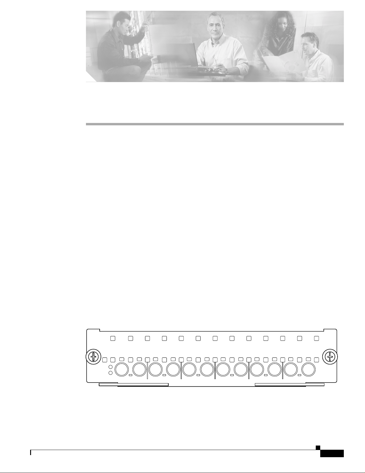
The 6-port 6T3 line card , shown in Figure 1-1, provides up to 24 network interfaces per Cisco 7304
router.
Figure 1-1 6T3 Line Card
7300-6T3
OIR
STATUS
6-PORT T3 DSU
TX
LNK
RX
0
TX
LNK
RX
1
TX
LNK
RX
2
TX
LNK
RX
3
TX
LNK
RX
4
TX
RX
5
LNK
66771
OL-3449-02
Clear Channel 6-Port T3 (DS3) Line Card Installation and Configuration
1-1
Page 14

Features
Features
Chapter 1 Overview
The 6T3 line card provides the following features:
• Single-wide line ca rd for t he Cisco 73 04 ro uter
• Full-duplex synchronous serial DS 3 interface
• High-Level Data Link Control (HDLC) data
• Integrated data serv i ce u nit (DS U) fu nctio na lity
• Support for 16- and 32-bit cyclic redundancy ch ecks (CR Cs)
• Support for Frame Relay, HDLC, and PPP serial encapsulations
• Support for DS3 MIB (RFC 1407)
• Support for remote and local loopb acks
• Six independent T3 port s
• Subrate DS3 support for Cisco , Kentrox, Larsco m, and Di gital Link format s along wit h the
associated scrambling. In so me m ode s, the scram bling is op tional.
• Clear-channel DS 3 (f rame d but un ch an neli z ed)
• M23 and C-bit-pari ty DS3 fr ame fo rmats
• Extraction of BOCs on the C -bit far-end a la rm a nd co ntro l (FE AC) code
• Detects and co un ts r e mote a lar m indi cati on (R AI ), par ity e rro rs, far-en d b lo ck err or (FE BE ), li ne
code violation (LCV), loss of light (LOL), out of frame (OOF), framing errors, loss of frame (LOF),
loss of signal (LOS)
• One-second perform ance mon itoring co unters
• Generates AIS and FEAC
• Generates F-, X-, P-, and M-bit errors; LCVs; all zeros; RAI; and FEBE f or testing
• Line, payload, and d iagn osti c l oop backs
• One bicolor LED per T 3 por t
• Drives up to 900 feet of 7 5-o hm c oaxi al cabl e RG - 59U or eq uivalent, 450 feet to D SX -3
demarcation point (DSX)
• 75-ohm SMB-type coa xia l c onn ect ions over ATT 734/728, 75-ohm coaxial ca ble
• B3ZS line coding
• Maintenance data link ( MDL) messages
• Bit error rate testing
1-2
Clear Channel 6-Port T3 (DS3) Line Card Installation and Configuration
OL-3449-02
Page 15
Chapter 1 Overview
Interoperability Guidelines for 6T3 Line Card DSUs
Interoperability Guidelines for 6T3 Line Card DSUs
The 6T3 line card support s several types of integrated data ser vice unit s (DSUs). Table 1-1 lists the
feature compatibilities of 6T3 line card DSUs.
Table 1-1 Feature Compatibilities of 6T3 Line Card DSUs
Full Rate
DSU
Support
Adtran Yes No Yes No
DL3100 Yes Yes Yes No
Kentrox Yes Yes
Larscom Yes Yes Yes No
1. MDL (Maintenance Data Link)
2. The 6T3 line card supports scrambling and Kentrox subrate at the same time.
Maintenance Data Link Messages
T3 maintenance data link (MDL) messages are used to communicate iden tific ation informati on between
local and remote ports. T he type of in format ion inclu ded in MDL me ssages inc ludes the eq uipmen t
identification co de (EIC) , loc ation iden tification code (LIC), frame identification code (FIC), unit, Path
Facility Identificati on (PFI ), po rt n umb er, and G ene ra tor Ide ntifica tio n num be rs. T he values f or ea ch
piece of MDL message identification can be defined only by a network administ rator and are discussed
in ANSI T1.107.
For information on transporting M DL messag es betwee n source and destinat ion T3 ports on a Cisco
7304 router, refer to T3 Maintenanc e Data Link Message s on the Cisco 7304 Router.
Scrambling
Support
2
Subrate
Support MDL1 Support
2
Yes
No
LEDs
OL-3449-02
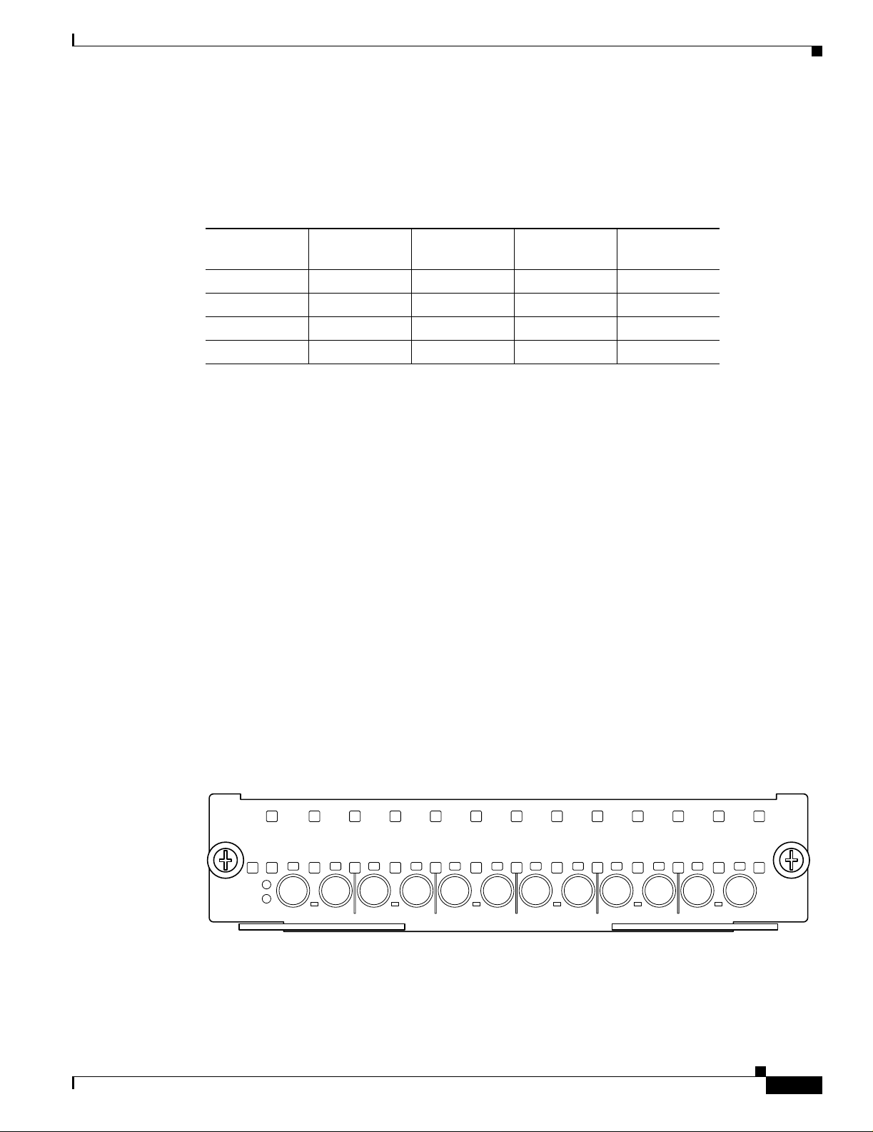
The 6-port 6T3 line card has six LNK LEDs , one for each port, as well as one OI R LED and one
STATUS LED. (See Figure 1-2.)
Figure 1-2 LEDs on t he 6T3 Line Card
7300-6T3
TX
OIR
STATUS
6-PORT T3 DSU
LNK
RX
0
TX
LNK
RX
1
TX
LNK
RX
2
TX
LNK
RX
3
TX
LNK
RX
4
TX
RX
5
LNK
After system initialization, the STATUS LED goes on to indicate that power is received and that the
6T3 line card is enabled for operation.
Clear Channel 6-Port T3 (DS3) Line Card Installation and Configuration
1-3
66771
Page 16

T3 SMB Cables
Chapter 1 Overview
The following conditions must all be met before the 6T3 line card is enabled:
• The 6T3 line card is correctly connected and receiving power.
• The Network Services Eng ine 100 (N SE-100 ) recogni zes the 6T 3 line card .
• The Cisco IOS image on the NSE- 100 is runnin g.
If any one of th ese conditions is not met, or if the initialization fails, the STATUS LED does not go on.
Table 1-2 lists 6T3 line card LED co lors and indications.
Table 1-2 6T3 Line Card LEDs
LED Label Color State Meaning
OIR Green On Line card is ready to be removed in
CLI-controlled OIR.
Off Line card is online.
STATUS Green/Yellow Green Indicates line card is online.
Yellow Indicates line card bootstrapping is in progress.
Off Indicates lin e card is offlin e or deactivated.
LNK Green/Yellow Green Line card port is enabled.
Yellow Line card port is in loopback m ode or i s r eceiving
or transmitting alarms.
Off Line card por t i s disab led.
T3 SMB Cables
The cables used to connect the 6T3 line card are presented in the following sections:
• Ordering Cables, pa ge 1 -6
• Building Your O wn Cabl es, p ag e 1- 6
We re comme nd usin g six T3 SMB cab les. The cables are 10 feet (3.0 48 meter s) long and have two
female SMB connectors on one end, and two female or male bayonet coupling (BNC) connectors on the
other end. Use the female SMB cable connectors to connect the local line card RX and TX ports. Use
the BNC cable connectors to connect the line card RX and TX ports to other devices. See Figure 3-2.
Note Cisco does not automatically provide the six T3 SMB cables recommended for your 6T3
line card.
1-4
Clear Channel 6-Port T3 (DS3) Line Card Installation and Configuration
OL-3449-02
Page 17
Chapter 1 Overview
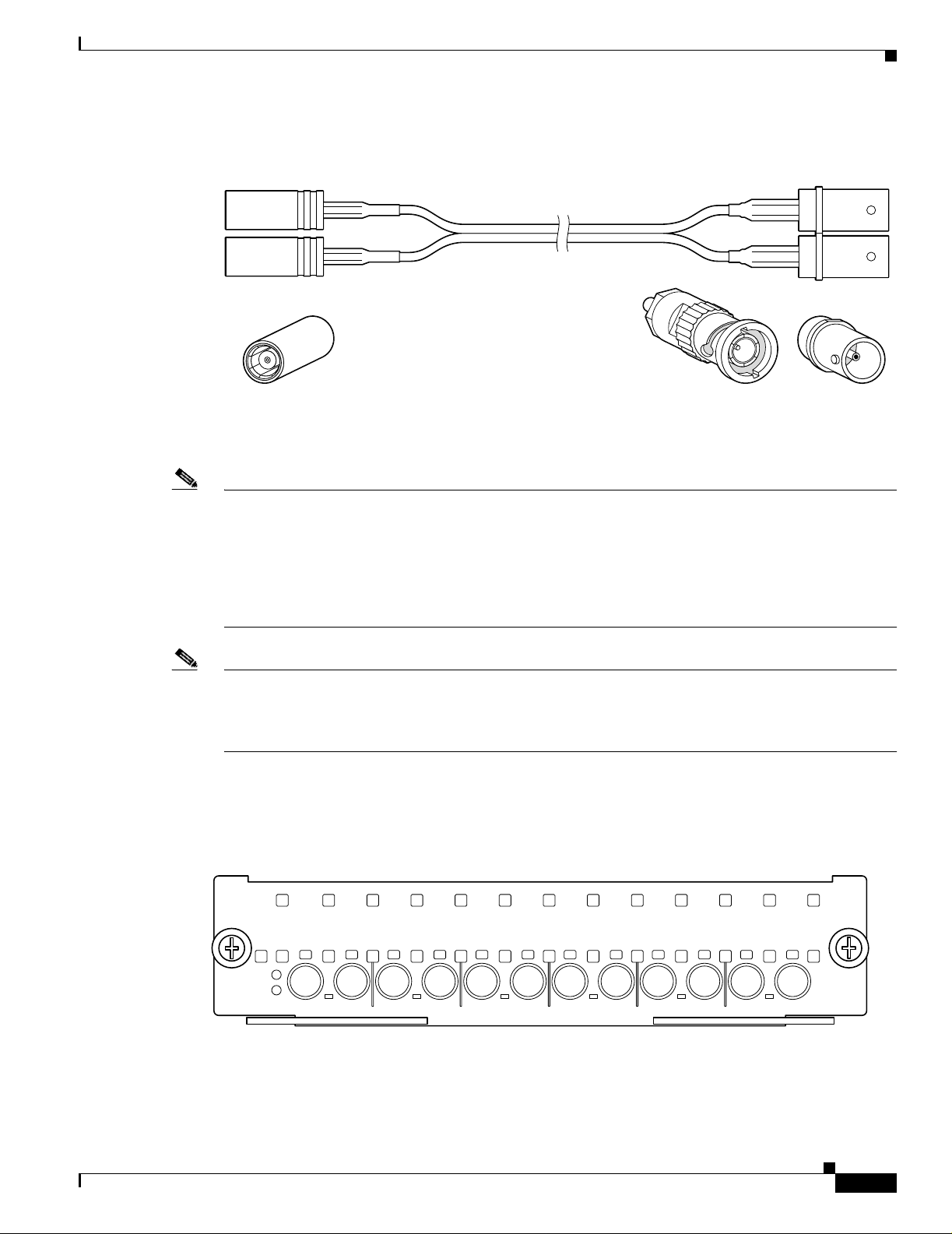
T3 SMB Cables
Figure 1-3 T3 SMB Cables (SMB Terminates into BNC)
70005
SMB connector Female BNC
Male BNC
connector
connector
Note Electromagnetic compliance (EMC) was verified with the 10-foot (3.048 meters) shielded cables that
are orderable thr ough Cisc o. We recommend tha t you u se only the 1 0-f oot (3.048 m ete rs) shie lde d T3
SMB cables; othe rwi se, E M C is not gua rant eed .
If you use cables other than those ordered from Cisco, it is your responsibility to ensure that you ha ve a
compliant system that meets local EMC requirements. To order additional cables, use the product
numbers: 2CBLE-SMB-BNC-M (ma le) and 2CBLE-SMB-BN C-F (female).
Note When you connect the 10-foot (3.048 meters) shielded T3 SMB cables to the 6T3 line card,
be careful not to be nd the m ale ca ble conn ec tor pi n w he n you c onn ect or dis con nect the
cables. Observe the receive (RX) and tra nsmit (T X) cabling re lation ship shown in
Figure 1-4.
Figure 1-4 Connecting T3 SMB Cables
OL-3449-02
7300-6T3
OIR
STATUS
6-PORT T3 DSU
TX
LNK
RX
0
TX
LNK
RX
1
TX
LNK
RX
2
TX
LNK
RX
3
TX
LNK
RX
4
TX
RX
5
LNK
66771
Clear Channel 6-Port T3 (DS3) Line Card Installation and Configuration
1-5
Page 18

T3 SMB Cables
After you connect the cables to a config ured port on the line card, it takes up to 35 seconds to initialize
the line card and light the green LNK LED.
Ordering Cables
You must order cables separately with the 6T3 line card when you order a Cisco 7304 router. Cables are
not automatically incl uded with the 6T3 line car d. Be su re t o speci fy the type of cable y ou w ant sh ippe d
with your card (2CB LE -SMB-B NC -M [ ma le] or 2 CBL E-SMB- BNC-F [f ema le]) .
Building Your Own Cables
You can build your own cables for the 6T3 line card by using the cable components listed in Table 1-3.
All three cables have an SMB connec tor at one end to conn ect to the 6T3 line ca rd. Th e two
SMB-to-BNC cables in Table 1-3 differ only in that one terminates in a male BN C connector, while the
other terminates in a fe ma le BNC co nnecto r. You can use the back-to-back cable for di re ctly con necti ng
two closely-spaced 6T3 line cards back-to-back . These cables should be shielded and have SMB
connectors on both ends.
Chapter 1 Overview
Note Back-to-back configurati ons, (6T 3 line car d serial-t o-6T3 line card serial port
configurations) require a specially built SMB-to-SMB cable. Table 1-3 provides cable
connector specifications. Or you can use the 2CBLE-SMB-BNC-M 10-foot (3.048 meters)
shielded cabl e and the 2C BLE -SM B-B NC -F 10 -foo t (3 .04 8 mete rs ) shi elde d cab le
connected together.
You can ord er the SMB- to-BN C cable s f rom Cisc o as pr odu ct num bers 2 CBL E-SMB -BN C-F (f e male)
or 2CBLE-SMB-BNC-M (male) BNC terminations, respectively. Cisco does not sell the SMB-to-SMB
cable.
Table 1-3 Cable Connector Specifications
Cable Configuration Line Card End Remote End RG-179 Cable
SMB-to-BNC Male ITT-Cannon
051-124-9859-C9A
SMB-to-BNC Female ITT-Cannon
051-124-9859-C9A
SMB-to-SMB
Back-to-Back
ITT-C annon
051-124-9859-C9A
Radial R142076000
(or equivalent)
Amp 41360-4
(or equivalent)
Amp 413760-8
(or equivalent)
ITT-Ca nnon
051-124-9859-C9A
Double-shielded
Harbour Ind. H6233- 1
(or equivalent)
Double-shielded
Harbour Ind. H6233- 1
(or equivalent)
Double-shielded
Harbour Ind. H6233- 1
(or equivalent)
1-6
Clear Channel 6-Port T3 (DS3) Line Card Installation and Configuration
OL-3449-02
Page 19

Chapter 1 Overview
Caution Cisco assumes no responsibility for system operation with other than Cisco-supplied
Management Inform ation Base
adapter cables. The customer is responsible for ensuring that any customer-built cables
meet all of the applicable compliance requirements (see the “Re lated Doc umentat ion”
section on page viii).
T3 systems are designed for cable lengths of 450 feet (137 meters) between the transmitter and the
DSX-3 demarcation point where the standa rd pulse mas k must be met . From the DS X-3 point, another
run of 450 feet (137 meters) is allowed to the receiver, making a total of 900 f ee t (274 meters) between
transmitter and receiver. This limitation is due to signal attenuation in the cable.
Although the American National Standards Institute (ANSI) sta ndard T 1.404 -1994 stipulates th e
Western Electric or equivalent 728A SMB cable, it has been replaced by the Lucent (formerly AT&T)
734A cable. Cisco tested more tha n 900 feet (27 4 meters) of 734 A SMB cable fr om transmitt er to
receiver including the SM B-to- BN C a dapt er ca ble s to veri fy hig h sig na l at te nuat ion.
Table 1-4 lists some approximate attenuation values from the ANSI standar d, and shows the RG-179
attenuation. RG-179 has a much higher attenuation, so take this information into account if you plan long
runs of RG-179 ca ble.
Table 1-4 ANSI Standard Cable-Attenuation Values
Approximate Cable Attenuatio n, dB1 from ANSI Stan dard T1.404-1 9 94
Frequency 100 ft (30 meters) DSX-3 Point
450 ft (137 meters) 900 ft (274 meters) 100 ft (30 meters)
1 MHz 0.27 1.2 2.4 3.0
10 MHz 0.80 3.6 7.2 5.3
50 MHz 1.82 8.2 16.4 8.5
100 MHz 2.64 11.9 23.8 10.0
1. dB = decibels
Management Information Base
Management Information Base (MIB) attributes are readable and writable across Integrated Local
Management Interfa ce ( ILMI ) thro ugh use of the Simp le Network Ma nage ment Pr otocol (S NMP) .
The 6-port 6T3 line card supports the DS 3 i nterface MIB (RFC 1407) .
Transmitter-to-receiver
distance (max) RG-179
Line Card Slot Locations on the Supported Platform
This section discusses line card slot locations on the supported platfo rm. The illustration that follows
summarizes slot loc a tion conventions o n th e Cisco 7 304 ro uter :
• Cisco 7304 Router Sl ot Numb er ing, pa ge 1 -8
Clear Channel 6-Port T3 (DS3) Line Card Installation and Configuration
OL-3449-02
1-7
Page 20

Line Card Slot Locations on the Supported Platform
Cisco 7304 Router Slot Numbering
Figure 1-5 shows a Cisco 7304 with the network se r vices eng ine (NSE ) in stall ed in slot s 0 and 1 and
line cards installed in slots 2 through 4. In the Cisco 7304, slot 0 is in the lower left position, and slot 5
is in the upper right position.
Figure 1-5 Slots in the Cisco 7304 Router
Slot 4
7300-6T3
Chapter 1 Overview
S
T
6-PORT T3 DSU
9K-10C48
S
T
A
1
-
P
O
R
T
Slot 0
TX
RX
O
IR
0
A
T
U
S
O
I
R
T
U
S
O
C
4
8
P
O
TX
RX
1
LNK
S
w
/
S
M
S
R
TX
RX
2
LNK
TX
RX
3
LNK
T
X
TX
RX
4
LNK
R
X
TX
RX
5
LNK
LNK
9
K
-4
0
C
3
/P
O
S
-M
M
O
O
I
I
R
R
S
S
T
T
A
A
T
T
U
U
S
S
4
-
P
O
R
T
O
C
3
0
1
P
O
S
w
/
M
M
C
A
R
A
2
R
I
E
R
/
L
A
R
M
3
A
C
T
I
V
E
/
L
O
O
P
B
A
C
K
Slot 2
Slot 5
66944
Slot 3
Slot 1
1-8
Clear Channel 6-Port T3 (DS3) Line Card Installation and Configuration
OL-3449-02
Page 21

Chapter 1 Overview
Identifying Interface Addresses
Identifying Interface Addresses
This section describes how to identify interface addresses for the 6T3 line card in the Cisco 7304 router.
Interface addresses specify the actual physical location of each interface on a router or switch.
Interfaces on the 6T3 line card installed in a router maintain the same address rega rdless of whether other
line cards are installed or removed. However, when you move a line card to a different slot, the first
number in the interface address changes to reflect the new slot number.
Table 1-5 explains how to identify interface addresses.
Table 1-5 Identifying Interface Addresses
Platform Interface Addr ess Form at Numbers Syntax
Cisco 7304 rou ter Slot-number/inte rface -po rt-n umb er Slot—2 through 5
Interface port— 0 through 5)
1. Slot 0 and slot 1 are reserved for the dual-width network services engine (NSE).
1
4/0
Cisco 7304 Router Interface Addresses
This section describes how to identify the interface addresses used for the 6T3 line card in the
Cisco 7304 router. The interface address is composed of a two-part number in the format
slot-number/interface-port- number. See Table 1-5 for the inte rfac e a ddr ess fo rm at .
In the Cisco 7304 router, slots are numbered from the lower left to the upper right, beginning with slot 0
and continuing through slot 5. (Slot 0 and slot 1 are reserved for the NSE.)
The interface address of the interfaces on a 6- port 6T3 line card in slot 2 are 2/0 through 2/5 (slot 2 a nd
interfaces 0 through 5). If the 6T3 line card was in sl ot 4, these same interfaces would be numbered 4/ 0
through 4/5 (slo t 4 an d in terfa ces 0 thr oug h 5).
OL-3449-02
Clear Channel 6-Port T3 (DS3) Line Card Installation and Configuration
1-9
Page 22

Identifying Interfac e Addresses
Chapter 1 Overview
1-10
Clear Channel 6-Port T3 (DS3) Line Card Installation and Configuration
OL-3449-02
Page 23

Preparing for Installation
This chapter describes the general equipme nt, safety, and site preparation requirements for installing the
6T3 line card. This chapter contains the following sections:
• Required Tools and Equipment, page 2-1
• Software and H ardwa re Req u ire men ts, p age 2-2
• 75-Ohm In-Line Coa xia l A tten uat or ( O pti onal ), pa ge 2-2
• Safety Guidelines, page 2-2
Required Tools and Equipment
You need the following tools and parts to install a line card. If you need additional equipment, contact
a service representa tive for ordering inform atio n.
CHAPTER
2
• 6T3 line card
• T3 SMB interface cables
• Number 2 Phillips screwdriver
• Your own electrosta tic disch arge (ESD)-pr evention equipme nt or the dispo sable gro undin g wrist
strap included wi th a ll u pgrad e kit s, field-r epl ace able u nit s ( FRUs), and spa res
• Antistatic mat
• Antistatic container
• Attenuator kit (optional)
OL-3449-02
Clear Channel 6-Port T3 (DS3) Line Card Installation and Configuration
2-1
Page 24

Software and Hardwar e Requirements
Software and Hardware Requirements
Table 2-1 lists the recommended minimum Cisco IOS software release required to use the 6-port 6T3
line card in the 7304 router platform.
Table 2-1 6T3 Line Card Software Requirements
Router Platform Recommended Minim u m Cis co IOS Release
Cisco 7304 Router
1. The 6T3 line card requires a Network Services Engine 100 (NSE-100) to operate.
1
Cisco IOS Rele ase 12 .1(10)EX or a later re lease of Cisco IOS Release 12.1 EX
75-Ohm In-Line Coaxial Attenuator (Opt ional)
A 75-ohm in-line c oaxi al atte nu ator m ay be requi red t o tu ne t he si g nal bet wee n the 6T3 l ine card a nd
the far-end equipmen t if the line card is exper iencing lin e code viol ations (L CVs). LCVs o ccur when th e
far-end equipment transmit signal satur ates the front -end rec eiver of the 6T3 line card.
Cisco offers an attenuator kit (ATTEN-KIT-PA=) that contains five attenuators with fixed values
ranging from 3 dB to 20 dB. For more information on the attenuator kit, go to the following URL:
http://www.cisco.com/univercd/cc/td/doc/product/core/7206/fru/12884att.htm
Chapter 2 Preparing for Installation
Safety Guidelines
This section provides safety guidelines that you should follow when working with any equipment that
connects to el ect ric al power or te leph one wi rin g.
Caution The 6T3 lin e card is n ot intend ed for dir ect con nection to outside t elecommuni cation lines. If connected
to an outside telecommunication line, suitable protection devices need to be provided.
Safety Warnings
Safety warnings app ear thro ugh out thi s pu bli cati on in p roce dur es t hat, if per for med in corre ct ly, might
harm you. A warn ing symb ol p re cede s each wa rnin g state men t.
2-2
Clear Channel 6-Port T3 (DS3) Line Card Installation and Configuration
OL-3449-02
Page 25

Chapter 2 Preparing for Installatio n
Warning Definition
Safety Guidelines
Warning
Waarschuwing
IMPORTANT SAFETY INSTRUCTIONS
This warning symbol means danger. You are in a situation that could cause bodily injury. Before you
work on any equipment, be aware of the hazards involved with electrical circuitry and be familiar
with standard practices for preventing accidents. To see translations of the warnings that appear in
this publication, refer to the translated safety warnings that accompanied this device.
Note: SAVE THESE INSTRUCTIONS
Note: This documentation is to be used in conjunction with t he specific product instal lat ion guide
that shipped with the product. Please refer to the Installation Guide, Configuration Guide, or other
enclosed additional documentation for further details.
BELANGRIJKE VEILIGHEIDSINS TRUC TIE S
Dit waarschuwingssymbool betekent gevaar. U verkeert in een situatie die lichamelijk letsel kan
veroorzaken. Voordat u aan enige apparatuur gaat werken, dient u zich bewust te zijn van de bij
elektrische schakelingen betrokken risico's en dient u op de hoogte te zijn van de standaard
praktijken om ongelukken te voorkomen. Voor een vertali ng van de waarschuwingen die in deze
publicatie verschijnen, dient u de vertaalde veiligheidswaarschuwingen te raadplegen die bij dit
apparaat worden geleverd.
Opmerking BEWAAR DEZE INSTRUCTIES.
Opmerking D eze documentatie dient gebruikt te worden in combinatie met de
installatiehandleiding voor het specifieke product die bij het product wordt geleverd. Raadpleeg de
installatiehandleiding, configuratiehandleiding of andere verdere ingesloten documentatie voor
meer informatie.
OL-3449-02
Varoitus
TÄRKEITÄ TURVALLISUUTEEN LIITTYVIÄ OHJEITA
Tämä varoitusmerkki merkitsee vaaraa. Olet tilanteessa, joka voi johtaa ruumiinvammaan. Ennen
kuin työskentelet minkään laitteiston parissa, ota selvää sähkökytkentöihin liittyvist ä vaaroista ja
tavanomaisista onnettomuuksien ehkäisykeinoista. Tässä asiakirjassa esitettyjen varoitusten
käännökset löydät laitteen mukana toimitetuista ohjeista.
Huomautus SÄILYTÄ NÄMÄ OHJEET
Huomautus Tämä asiakirja on tarkoitettu käytettäväksi yhdessä tuotteen mukana tulleen
asennusoppaan kanssa. Katso lisätietoja asennusoppaasta, kokoonpano-oppaasta ja muista
mukana toimitetuista asiakirjoista.
Clear Channel 6-Port T3 (DS3) Line Card Installation and Configuration
2-3
Page 26

Safety Guidelines
Chapter 2 Preparing for Installation
Attention
Warnung
IMPORTANTES INFORMATIONS DE SÉCU RI TÉ
Ce symbole d'avertissement indique un danger . V ous vous trouvez dans un e situation pouvant causer
des blessures ou des dommages corporels. Avant de travailler sur un équipement, soyez conscient
des dangers posés par les circuits électriques et familiarisez-vous avec les procédures couramment
utilisées pour éviter les accidents. Pour prendre connaissance des traductions d'avertissements
figurant dans cette publication, consultez les consignes de sécurité traduites qui accompagnent cet
appareil.
Remarque CONSERVEZ CES INFORMATIONS
Remarque Cette documentation doit être utilisée avec le guide spécifique d'install ation du produit
qui accompagne ce dernier. Veuillez vous reporter au Guide d'installation, au Guide de
configuration, ou à toute autre documentation jointe pour de plus amples renseignements.
WICHTIGE SI CHERHE ITSAN WEIS UNGEN
Dieses Warnsymbol bedeutet Gefahr. Sie befinden sich in einer Situation, die zu einer
Körperverletzung führen könnte. Bevor Sie mit der Arbeit an irgendeinem Gerät beginnen, seien Sie
sich der mit elektrischen Stromkreisen verbundenen Gefahren und der Standardpraktiken zur
Vermeidung von Unfällen bewusst. Übersetzungen der in dieser Veröffentlichung enthaltenen
Warnhinweise sind im Lieferumfang des Geräts enthalten.
Hinweis BEWAHREN SIE DIESE SICHERHEITSANWEISUNGEN AUF
Hinweis Dieses Handbuch ist zum Gebrauch in Verbindung mit dem Installationshandbuch für Ihr
Gerät bestimmt, das dem Gerät beiliegt. Entnehmen Sie bitte alle weiteren Informationen dem
Handbuch (Installations- oder Konfigurationshandbuch o. Ä.) für Ihr spezifisches Gerät.
Figyelem!
Avvertenza
FONTOS BIZTONSÁGI ELÕÍRÁSOK
Ez a figyelmezetõ jel veszélyre utal. Sérülésveszélyt rejtõ helyzetben van. Mielõtt bármely
berendezésen munkát végezte, legyen figyelemmel az elektromos áramkörök okozta kockázatokra,
és ismerkedjen meg a szokásos balesetvédelmi eljárásokkal. A kiadványban szereplõ
figyelmeztetések fordítása a készülékhez mellékelt biztonsági figyelmeztetések között található.
Megjegyzés ÕRIZZE MEG EZEKET AZ UTASÍTÁSOKAT!
Megjegyzés Ezt a dokumentációt a készülékhez mellékelt üzembe helyezési útmutatóval együtt kell
használni. További tudnivalók a mellékelt Üzembe helyezési útmutatóban (Installation Guide),
Konfigurációs útmutatóban (Configuration Guide) vagy más dokumentumban találhatók.
IMPORTANTI ISTRUZIONI SULLA SICUREZZA
Questo simbolo di avvertenza indica un pericolo. La situazione potrebbe causare infortuni alle
persone. Prima di intervenire su qualsiasi apparecchiatura, occorre essere al corrente dei pericoli
relativi ai circuiti elettrici e conoscere le procedure standard per la prevenzione di incidenti. Per le
traduzioni delle avvertenze riportate in questo documento, vedere le avvertenze di sicurezza che
accompagnano questo dispositivo.
Nota C ONSERVARE QUESTE ISTRUZIO NI
Nota La presente documentazione va usata congiuntamente alla guida di install azione specifica
spedita con il prodotto. Per maggiori informazioni, consultare la Guida all'installazione, la Guida
alla configurazione o altra documentazione acclusa.
2-4
Clear Channel 6-Port T3 (DS3) Line Card Installation and Configuration
OL-3449-02
Page 27

Chapter 2 Preparing for Installatio n
Safety Guidelines
Advarsel
Aviso
VIKTIGE SIKKERHETSINSTRUKSJONER
Dette varselssymbolet betyr fare. Du befinner deg i en situasjon som kan forårsake personskade.
Før du utfører arbeid med utstyret, bør du være oppmerksom på farene som er forbundet med
elektriske kretssystemer, og du bør være kjent med vanlig praksis for å unngå ulykker. For å se
oversettelser av advarslene i denne publikasjonen, se de oversatte sikkerhetsvarslene som følger
med denne enheten.
Merk TA VARE PÅ DISSE INSTRUKSJONENE
Merk D enne dokumentasjonen skal brukes i forbindelse med den spesifikke
installasjonsveiledningen som fulgte med produktet. Vennligst se installasjonsveiledningen,
konfigureringsveiledningen eller annen vedlagt tilleggsdokumentasjon for detaljer.
INSTRUÇÕES IMPORTANTES DE SEGURANÇA
Este símbolo de aviso significa perigo. O utilizador encontra-se numa situação que poderá ser
causadora de lesões corporais. Antes de iniciar a utilização de qualquer equipamento, tenha em
atenção os perigos envolvidos no manuseamento de circuitos eléctricos e familiarize-se com as
práticas habituais de prevenção de acidentes. Para ver traduções dos avisos incluídos nesta
publicação, consulte os avisos de segurança traduzidos que acompanham este dispositivo.
Nota GUARDE ESTAS INSTRUÇÕES
Nota Esta documentação destina-se a ser utilizada em conjunto com o manual de instalação
incluído com o produto específico. Consulte o manual de instalação, o manual de configuração ou
outra documentação adicional inclusa, para obter mais informações.
¡Advertencia!
Varning!
INSTRUCCIONES IMPORTANTES DE SEGURIDAD
Este símbolo de aviso indica peligro. Existe riesgo para su integridad física. Antes de manipular
cualquier equipo, considere los riesgos de la corriente eléctrica y familiarícese con los
procedimientos estándar de prevención de accidentes. Vea las traducciones de las advertencias
que acompañan a este dispositivo.
Nota GUARDE ESTAS INSTRUCCIONES
Nota Est a documentación está pensada para ser utilizada con la guía de instalación del producto
que lo acompaña. Si necesita más detalles, consulte la Guía de instalación, la Guía de
configuración o cualquier documentación adicional adjunta.
VIKTIGA SÄKERHETSANVISNINGAR
Denna varningssignal signalerar fara. Du befinner dig i en situation som kan leda till personskada.
Innan du utför arbete på någon utrustning måste du vara medveten om farorna med elkretsar och
känna till vanliga förfaranden för att förebygga olyckor. Se översättningarna av de
varningsmeddelanden som finns i denna publikation, och se de översatta säkerhetsvarningarna som
medföljer denna anordning.
OBS! SPARA DESSA ANVISNINGAR
OBS! Denna dokumentation ska användas i samband med den specifika
produktinstallationshandbok som medföljde produkten. Se installationshandboken,
konfigurationshandboken eller annan bifogad ytterligare dokumentation för närmare detaljer.
OL-3449-02
Clear Channel 6-Port T3 (DS3) Line Card Installation and Configuration
2-5
Page 28

Safety Guidelines
Chapter 2 Preparing for Installation
2-6
Clear Channel 6-Port T3 (DS3) Line Card Installation and Configuration
OL-3449-02
Page 29

Chapter 2 Preparing for Installatio n
Safety Guidelines
Electrical Equipment Guidelines
Follow these basic guidelines when working with any electrical equipment:
• Before beginning any procedure requiring access to the chassis interior, locate the emergency
power-off switch for the room i n whi ch y ou ar e worki ng.
• Disconnect all power and external cables before moving a chassis.
• Do not work alone when potentially hazardous conditions exist.
• Never assume that power has been d isco nnecte d from a c ircui t; always check.
OL-3449-02
Clear Channel 6-Port T3 (DS3) Line Card Installation and Configuration
2-7
Page 30

Safety Guidelines
• Do not perform any action that create s a poten tia l hazar d to people or mak es the eq uipm en t unsafe;
carefully examine y our wor k ar ea for po ssi ble haz ards such as moist f loor s, ung rou nded power
extension cables, and m issin g safety gr oun ds.
Telephone Wiring Guidelines
Use the following guidelines when working with any equipment that is connected to telephone wiring
or to other network cabling:
• Never install telephone wiring during a l ightning storm.
• Never install telephone jacks in wet locations unless the jack is specifically designed for wet
locations.
• Never touch uninsulated telephone wir es or termin als unless th e telepho ne line has been
disconnected at t he n etwor k in ter face.
• Use caution when instal ling or modifying t elepho ne lines.
Preventing Electrostatic Discharge Damage
Chapter 2 Preparing for Installation
Electrostatic dis charge (ESD) damage, which can occur when electronic cards or components are
improperly handled, results in complete or intermittent failures. Line cards and processor modules
consist of printed circuit boards that are fixed in metal carriers. Electromagnetic interference (EMI)
shielding and connectors are integral components of the carrier. Although the metal carrier helps to
protect the board from ES D, use a preventive antistatic strap duri ng handling .
Following are guidelines for preventing ESD damage:
• Always use an ESD w ris t o r ank l e st rap a nd ensu re tha t i t m akes go od skin co nta ct.
• Connect the equipmen t end of the strap t o an unfinished chassis surface .
• When installing a component, use any available ejector levers or captive installation screws to
properly seat the bus connectors in the backplane or midplane. These devices prevent accidental
removal, provide proper grou ndi ng f or the syste m, and he lp to e nsu re t ha t bus co nnec tors ar e
properly seated.
• When removing a component, use any available ejector levers or captive installation screws to
release the bus connectors from the backplane or midplane.
• Handle carriers by available handl es or e dg es on ly ; avoid touchi ng the pri nted ci rcui t b oar ds or
connectors.
• Place a removed board component-side-up on an antistatic surface or in a static shielding container.
If you plan to return the component to the factory, immediately place it in a static shielding
container.
• Avoid contact between the printed circuit boards and clothing. The wrist strap protects components
from ESD voltages on the body only; ESD voltages on clothing can still cause damage.
• Never attempt to remove the printed circuit board from the metal carrier.
2-8
Caution For safety, periodically check the resistance value of the antistatic strap. The measurement should be
between 1 and 10 megohms (M ohms) .
Clear Channel 6-Port T3 (DS3) Line Card Installation and Configuration
OL-3449-02
Page 31

Removing and Installing Line Cards
This chapter describes ho w to remo ve the 6 T3 line card from su pported platforms and a lso how to install
a new or replaceme nt l ine ca rd. Thi s c hap te r co nt ain s t he f ol lowing sec ti ons:
• Installation Overview, page 3-1
• Handling Line C ards, page 3 -2
• Online Insertio n and R em oval, page 3- 2
• Warn ings an d Cautio ns, page 3-3
• Line Card Removal and Installation, pa ge 3-3
• Connecting a T3 SMB Cable, page 3- 5
Installation Overview
CHAPTER
3
Each line card circuit board is mounted to a metal ca rrier and is sensiti v e to electrost atic discharg e (ESD)
damage.
Note When a line card slot is not in use, a blank lin e card must fill the empty slot to allo w the router to conform
to electromagnet ic interferen ce (EMI) emissio ns requireme nts and to allo w proper air flow acr oss the line
cards. If you plan to install a new line card in a slot that is not in use, you must first remove the blank
line card.
OL-3449-02
Clear Channel 6-Port T3 (DS3) Line Card Installation and Configuration
3-1
Page 32

Handling Line Cards
Handling Line Cards
Caution Always handle the line car d by the ca rr ier edge s and han dle; never tou ch t he l ine ca rd co mpone nts or
connector pins. (See Figure 3-1.)
Figure 3-1 Handling a Line Card
Chapter 3 Removing and Installing Line Cards
Printed circuit board
70006
Metal carrier
GND
Online Insertion and Removal
The Cisco 7304 router sup por ts onl ine inser ti on and r em oval (OIR) of line card s; the ref ore , you do not
have to power down the router when removing and replacing a 6T3 line card on a Cisco 7304 router. The
Cisco 7304 router al so suppor ts CLI-c ontrolled OIR (see the “CLI-Con trolled OIR ” section on
page 4-17), which allows for the completion of data traffic before the active interfaces are shut down.
Note CLI-controlled O IR i s the re comm en de d way of pe rf or ming OIR on thi s p lat form .
Note As you disengage the line card from the router, online insertion and removal (OIR) administratively
shuts down all active inter faces on the line card.
Note Before you begin installation, read Chapte r 2, “Preparing for Insta llation, ” fo r a list of parts and too ls
required for installation.
3-2
Clear Channel 6-Port T3 (DS3) Line Card Installation and Configuration
OL-3449-02
Page 33

Chapter 3 Removing and Installin g Line Cards
Warnings and Cautions
Observe the following warnings and cautions when installing or removing line cards.
Caution Do not slide a line card all the way into the slot until you have connected all required cables. Trying to
do so disrupts normal operation of the router or sw itch.
Note If a line card lever or other retaining mechanism does not move to the locked position, the line card is
not completely seated in the backplane. Carefully pull the line card halfway out of the slot, reinsert it,
and move the line card levers to the locked position.
Caution To prevent ja mming t he carr ier betwe en the u pper and the lo wer edges of the line card slot, an d to ens ure
that the edge connector at the rear of the line card mates with the connection at the rear of the line card
slot, make certain that the carrier is positioned correctly, as s hown in the cutaway in the following
illustrations.
Warnings and Cautions
Warning
When performing the following procedures, wear a grounding wrist strap to avoid ESD damage to the
card. Some platforms have an ESD connector for attaching the wrist strap. Do not directly touch the
midplane or backplane with your hand or any metal tool, or you could shock yourself.
Line Card Removal and Installation
In this section, the illustrations that follow give step-by-step instructions on how to remove and install
line cards. This section contains the following illustrations:
• Cisco 7304—Rem oving and Instal ling a Lin e Card, pag e 3-4
OL-3449-02
Clear Channel 6-Port T3 (DS3) Line Card Installation and Configuration
3-3
Page 34

Chapter 3 Removing and Installing Line Cards
Line Card Removal and Instal lation
Cisco 7304—Removing and Installing a Line Card
1. To remove the line card, loosen the locking thumbscrews on both sides of the line card.
2. Pull out the line card levers and carefully slide the line card halfway out of the slot. If you are removing a
blank line card, pull the blank line card completely out of the chassis slot.
3. With the line card halfway out of the slot, disconnect all cables from the line card. After disconnecting the
cables, pull the line card out of the chassis slot.
4. To insert the line card, carefully align the edges of the carrier or printed circuit board between the upper
and the lower edges of the chassis slot.
5. Carefully slide the new line card halfway into the line card slot and connect all required cables.
6. With the cables connected, carefully slide the line card into the slot until the line card makes contact with
the backplane.
NOTE: The line card levers must be positioned at a 45-degree angle before the line card makes contact
with the backplane.
7. Push the line card levers in until the line card is fully seated in the router backplane.
NOTE: When the chassis is fully populated, seating a new line card may be difficult. In order to properly
seat the line card and avoid physical damage, loosen the thumbscrews on the neighboring line cards.
CAUTION: Use of excessive force to seat the line card may damage the router or line card.
8. Tighten the locking thumbscrews on both sides of the line card.
Clear Channel 6-Port T3 (DS3) Line Card Installation and Configuration
3-4
57891
OL-3449-02
Page 35

Chapter 3 Removing and Installin g Line Cards
Connecting a T3 SMB Cable
On a 6T3 line c ard, y ou ca n use si x T3 SM B cabl es ( one for e ach T3 link) .
Each T3 link requires sep arate rec eive and transmit conn ecti ons to your externa l T3 equi pment.
To connect the T3 SMB cables to the 6T3 line card, follow these steps:
Step 1 Attach the T3 SMB cables directly to the SMB ports on the 6T3 line card. Attach the SMB ends of the
cable to the p orts label ed T X a nd RX. (Se e Fi gure 3-2.)
Note If you build your own cables, we strongly recommend that you fasten together your transmit and receive
cables along their entire length, as shown in Figure 3-2. Doi ng so re du ce s th e effects of E MI . You can
use shielded jacketing or tubing for this p urpose.
Figure 3-2 Attaching T3 SMB Cables to a 6T3 Line Card
7300-6T3
Connecting a T3 SMB Cable
TX
R
X
0
LN
K
TX
R
X
1
LN
K
TX
R
X
2
LN
K
TX
R
X
3
LN
K
T
X
R
X
4
LN
K
TX
R
X
5
LN
K
To RX
OIR
STATUS
6-PORT T3 DSU
66946
To TX
Caution To prevent syste m prob lems and to mai ntain t he prop er ca ble co nnec tion se quen ces, co nne ct the rece i v e
and transmit ports on your 6T 3 line card as indicated in Step 2.
Step 2 Attach the BNC ends of your T3 SMB cables to your external T3 equipment as follows:
• Attach the T3 cable fro m the 6T3 line card TX po rt to the RX por t on your externa l T3 equip ment.
• Attach the T3 cable fro m the 6T3 line card RX por t to the TX por t on your exter nal T3 equip ment .
OL-3449-02
Clear Channel 6-Port T3 (DS3) Line Card Installation and Configuration
3-5
Page 36

Connecting a T3 SMB Cable
Chapter 3 Removing and Installing Line Cards
3-6
Clear Channel 6-Port T3 (DS3) Line Card Installation and Configuration
OL-3449-02
Page 37

Configuring the 6T3 Line Card
To c on tin ue yo ur 6T3 line card insta ll ation, y ou mu st configure the seri al int erfac es.
This chapter contains the following sectio ns:
• Using the EXEC Comma nd Interp reter, page 4-1
• Configuring the Interfaces, page 4-2
• Checking the Configurati on, p ag e 4- 9
• CLI-Controlled OIR, page 4-17
• Line Card Crash Recovery, page 4-17
Using the EXEC Command Interpreter
You modify the configuration of your router through the software command interpreter called the EXEC
(also called enable mode). You must enter the privileged level of the EXEC command interpreter with
the enable command before you can use the configure command to conf i gur e a new interface or change
the existing configuration of an interface . The syste m prompts you for a password if one has been set.
The system prompt for the privileged level ends with a pound sign (#) in stead of an angle bracke t (>).
At the console terminal, use the following procedure to enter the privileged level:
CHAPTER
4
OL-3449-02
Step 1 At the user-level EXEC prompt, e nter the enable co mma nd . The EXEC pr om pts y ou for a
privileged-level password as follows:
Router> enable
Password:
Step 2 Enter the password (the password is case sensitive). For security purposes, the password is not displayed.
When you enter the correct password, the system displays the privileged-level sy stem prompt (#):
Router#
To configure the new interfaces, proceed to the “Configuring the Interfaces” section on page 4-2.
Clear Channel 6-Port T3 (DS3) Line Card Installation and Configuration
4-1
Page 38

Configuring the Interfaces
Configuring the Interfaces
After you verify that the new 6 T3 line card is installed correctly (the STATUS LED goes on), use the
privileged-level configure command to configure the new interfaces. Have the following information
available:
• T3 information such as clock source and framing type
• Protocols you plan to route on each new interface
• IP addresses, if you plan to configure the in terfaces for IP routing
• Bridging protocols you plan to use
• Timing source for each new interface
If you installed a new 6T3 l ine car d or if yo u wa nt to c han ge the co nfigurati on o f an exi stin g in te rface,
you must enter configuration mode to configure t he new interfaces. If you replaced a 6T3 line card that
was prev iously configured, the system recognizes the ne w in terf aces and br ings ea ch of them up in their
existing configuration.
For a summary of the configuration options available and instructions for configuring interfaces on a
6T3 line card, refer to the ap p ropri ate c o nf iguration publications listed in the “Related Documentation”
section on page viii.
You execute configurati on comm ands fro m the privileged level of the EXEC co mmand in terpre ter,
which usually requ ires pa ssword ac cess. C ont act you r sy stem adm i nistra tor, if necessa ry, to obtain
password access. (See the “Using the EXEC Command Interpreter” section on page 4-1 for an
explanation of the privileged level of the EXEC.)
Chapter 4 Configuring the 6T3 Line Card
This section conta ins th e fo llowing su bse ctions :
• Shutting Down an Interface, page 4-2
• Performing a Basic C onfiguratio n, page 4- 4
• Customizing the 6T 3 L ine Card Co nfigurati on , pag e 4-6
Shutting Down an Interface
Before you remove an interface that you will not repla ce, or repla ce line ca rds, use the shutdown
command to shut down (disable) the interface s to prevent anomalies when you reinstall the new or
reconfigured interfac e pr oces sor. When you sh ut down a n inter face, it i s desi gnat ed ad ministratively
down in the show command displa ys.
Follow these steps to shut down an interface:
Step 1 Enter the privileged level of the EXEC command interpreter (also called enab le m ode) . (See th e “Using
the EXEC Command Interp reter ” sect ion on page 4-1 for instructi ons.)
Step 2 At the privileged- level prompt, en ter c onfigurat ion m ode a nd sp eci fy t ha t the c on sole t ermi nal is th e
source of the configuratio n su bcomm a nds, a s fol lows:
Router# configure terminal
Enter configuration commands, one per line. End with CNTL/Z.
Router(config)#
4-2
Step 3 Shut down interfaces by entering the interface seri al subc omma nd (f ollowed by the int erfa ce a dd ress
of the interface), and then enter the shutdown command. Table 4-1 shows the command syntax.
Clear Channel 6-Port T3 (DS3) Line Card Installation and Configuration
OL-3449-02
Page 39

Chapter 4 Configuring the 6T 3 Line Card
When you have finished, press Ctrl-Z—hold down the Control key while you press Z—or enter end or
exit to exit configuration mode and return to the EXEC command interpreter.
Table 4-1 Syntax of the shutdown Command
Platform Command Example
Cisco 7304 rou ter s interface, foll owe d by th e type
(serial) and slot/port (slot-number/
interface-port- num ber)
Note If you need to shut down additional interfaces, enter the interface serial command (followed by
the interface address of the interface) for each of the interfaces on your line card. Use the no
shutdown command to enable the interface.
The example is for interface 0 and interface 1 on a
6T3 line card in sl ot 2.
Router(config-if)# interface serial 2/0
Router(config-if)# shutdown
Router(config-if)# interface serial 2/1
Router(config-if)# shutdown
Ctrl-Z
Router#
Configuring the Interfaces
Step 4 Write the new configuration to NVRAM as follows:
Router# copy running-config startup-config
[OK]
Router#
The system displays an OK message when the c onfiguration has bee n stored in NVRAM.
Step 5 Verify that new interfaces are now in the correct state (shut down) using the
show interfaces command (followed by the interface type and interface address of the interface) to
display the specific interface. Table 4-2 provides examples.
Table 4-2 Examples of the show interfaces serial Command
Platform Command Exam pl e
Cisco 7304 rou ter show interfaces serial, followed
by slot/port (slot-number/
interface-port- num ber)
The example is for interface 0 on a
6T3 line card i n slot 2.
Router# show interfaces serial 2/0
Serial 2/0 is administratively down,
line protocol is down
[Additional display text omitted from
this example]
OL-3449-02
Clear Channel 6-Port T3 (DS3) Line Card Installation and Configuration
4-3
Page 40

Configuring the Interfaces
Step 6 Reenable interfaces by doing the following:
a. Repeat Step 3 to reenable an interface. Substitute the no shutdown command for the shutdown
command.
b. Repeat Step 4 to write the new configurat ion to memor y.
Use the copy running-config startup-config comm an d.
c. Repeat Step 5 to verify that the i nter faces ar e in th e corr ect state. Use the
show interfaces command followed by the interface type and interface address of the interface.
For complete descriptions of software configuration commands, refer to the pu blications listed in the
“Related Documentation” section on page viii.
Performing a Basic Config uratio n
Following are instructions for a basic con figuration: en abling an interface an d specify ing IP routin g.
You might also need to enter other configuration subcommands, depending on the requirements for your
system configuration and the pro toco ls you p lan t o rout e on t he i nte rface . For compl ete de sc ripti ons o f
configuration subcommands and the configuration options available for serial interfaces, refer to the
appropriate soft ware documen tati on.
In the following procedure, press th e Return key after each step unless otherwise noted. At any time
you can exit the pri vile ged le v e l and return to the user l e vel b y entering disable a t th e pr ompt as f oll o w s:
Router# disable
Chapter 4 Configuring the 6T3 Line Card
Router>
Step 1 Enter configuration mode and specify that the console terminal is the source of the configuration
subcommands, as follows:
Router# configure terminal
Enter configuration commands, one per line. End with CNTL/Z.
Router(config)#
Step 2 Specify the first interface to config ure by entering the interface serial subcommand, followed by the
interface address of the int erface you plan to co nfigure. Table 4-3 provides an example.
Table 4-3 Examples of the interface serial Subcommand
Platform Command Example
Cisco 7304 router interface serial, followed by
slot/port (slot-number/
interface-port- num ber)
Step 3 Assign an I P ad dress a nd s ubnet mask to t he in terface ( if IP r outing is enabl ed o n the syste m) by usin g
The example is for the first interface of a
6T3 line card in sl ot 4.
Router(config)# interface serial 4/0
Router(config-if)#
the ip address subcommand, as in the following example:
Router(config-if)# ip address 10.0.0.0 10.255.255.255
4-4
Step 4 Add any additional configuration subcommands required to enable routing protocols and set the
interface ch arac teri stic s.
Clear Channel 6-Port T3 (DS3) Line Card Installation and Configuration
OL-3449-02
Page 41

Chapter 4 Configuring the 6T 3 Line Card
Step 5 Reenable the interfaces using the no shutdown command. (See the “Shutting Down an Interface”
section on page 4-2.)
Step 6 Configure all additional line card interfaces as required.
Step 7 After including all of the configuration subcommands to complete your configuration, press
Ctrl-Z—hold down the Control key while you press Z—or enter end or exit to exit configuration mode
and return to the EXEC command interpreter prompt.
Step 8 Write the new configuration to NVRAM as follows
Router# copy running-config startupup-config
[OK]
Router#
This completes the pro cedure for crea ting a basi c configurat ion.
Table 4-4 shows the default values for the 6T3 line card serial interfaces.
Table 4-4 6T 3 Line Card Serial Interface Default Values
Parameter Configuration Command Default Value
Clock source clock source [internal | line] line
Cyclic redundancy check crc [16 | 32] 16
DSU mode [no] dsu mode [adtran | cisco | digital-link | kentrox|
DSU subrate bandwidth [no] dsu bandwidth kbps 44210
Encapsulation encapsulation [hdlc | ppp] hdlc
Far-end DSU bandwidth [no] dsu remote fullrate subrate
Framing mode [no] framing [c-bit | m23] c-bit
Idle character mode [no] idle-character [flags | marks] flags
Invert data [no] inver t data No invert data
Keepalive [no] keepalive [seconds] keepalive 10
Loopback mode [no] loopback [local | network line | network payload
Maximum transmission
unit
Payload scrambling [no] scramble no scramble
Remote requests [no] dsu remote accept accept
Transmitter delay [no] tr ansmit te r-delay # of id le cha ract ers 0–255
Cable length cable length {0–450}50
Configuring the Interfaces
cisco
larscom]
no loopback
| remote | dte]
[no] mtu bytes 4470 bytes
OL-3449-02
Clear Channel 6-Port T3 (DS3) Line Card Installation and Configuration
4-5
Page 42

Chapter 4 Configuring the 6T3 Line Card
Configuring the Interfaces
Customizing the 6T3 Line Card Configuration
There are two sides to the network, a local network side and a remote customer side, or near and far ends.
The 6T3 line card supports third-party data service units (DSUs), Internet Service Provider
(ISP)-provided DS3 lin es, a nd so o n. You can change the configuration p ar amete r default values i n t he
6T3 line card port in terfa ce s to m atch t h e remo te D SU s on you r ne twork. Table 4-5 shows the
configuration param ete rs.
Table 4-5 6T3 Line Card Serial Interface DSU Modes
Default
Parameter Configuration Command
DSU mode [no] dsu mode [adtran | cisco |
digital-link | kentrox| larscom]
DSU subrate bandwidth [no] dsu bandwidth kbps 44210 Router(confi g-i f) # dsu bandwidth
Far-end DSU bandwidth [no] dsu remote fullrate subrate Router(confi g-i f) # dsu remote
Payload scrambling [no] scramble
1
Remote requests [no] dsu remote accept accept Router(confi g-i f) # dsu remote
Cyclic red und an cy ch ec k crc [16 | 32] 16 R ou te r(c on fi g-i f) # crc 16
1. Adtran DSU mode does not support payload scrambling.
Value Command
cisco
no
Router(confi g-i f) # dsu mode ci sco
44210
fullrate
Router(confi g-i f) # scramble
scramble
accept
Note The local port and the remo te port must have matching con figuration.
Verifying Local and Remote DS3 Port Settings
You can use telnet to determine the DS U mode sett ings on the remote DS3 p ort. Once you verify the
remote DS3 port s etti ngs, y ou ca n negot iate ch ang ing co nfigurat ion pa rame ter s so tha t D SU mode
settings are the same on both the local and remote DS3 ports. You can set the DSU bandwidth to accept
or reject the incoming remote requests from the local DS3 port by entering the dsu remot e accept
interface configuration command.
Selecting a DSU Mode
The DSU mode supports several third-pa rty DSU vendors—Adtran, Digital Link, Kentrox, and
Larscom—an d the defaul t DSU mod e, Cisco. If you use a DSU to make the connect ion betw een the
Cisco 7304 router and another device, the local DS3 port configuration must match the remote DS3 port
configuration. There fo re, if th e re mo te DS3 po rt uses the Kentrox vend or, a requ est is se nt to the lo ca l
DS3 port to change the D S U mode to Kentrox, either by manually entering the dsu mode co nfigurati on
command and specifyi ng the Kentrox DSU or by using the Cisco Remo te Connec tion Ma nagement
(CRCM) feature to remotely configure t h e remote DS3 port. If you make a direct connection between a
Cisco 7304 router a nd a noth er device, you c an use th e Cisco DS U m ode.
4-6
Clear Channel 6-Port T3 (DS3) Line Card Installation and Configuration
OL-3449-02
Page 43

Chapter 4 Configuring the 6T 3 Line Card
Setting the Sending and Receiving Rate
The local and rem ot e D S3 por ts m ust al so agr e e on w he ther to use a s ubr ate or fu llra te sen di ng a nd
receiving rate, because the speed of the sending and receiving rate is regulated by the DSU mode. If the
sending and receiving rates do not match, they will not work. Subrates are specific to DSU modes and
must be configured appropria tely. The subrate sending a nd receiving rate is slower and less expensive
than the faster, m ore expensive, fullrate. You can synchronize the local and remote DS3 ports sending
and receiving rates by ent ering the dsu remote interface configuration command.
Configuring the DSU Bandwidth Range
The DSU bandwidth range is from 0 to 44210 kbp s. The loca l port an d the re mote por t must have
matching configuration. Therefore, if yo u reduce the effective bandwidth to 3000 on the local port, you
must do the same on the remote port by entering the dsu bandwidth interface configuration com mand.
In interface configuration mode, reduce effective bandwidth (range of 0 to 44210 kbps) by entering t h e
dsu bandwidth configuration subcommand, as in the following example:
Router(config-if)# dsu bandwidth 3000
Use the no form of this command to return to the default, 44210.
Configuring the Interfaces
Note The local port configuration must match th e remo te port configura tion.
Enabling Payload Scrambling
Payload (data) scrambling converts the data received by the local or remote DS3 ports from the Digital
Link, Kentrox, and Larscom third- party DSU vendor modes as w ell as the default , Cisco mod e. The
Adtran DSU mode does not support payload scrambli ng.
T o enable payload scrambling on the local and remote DS3 ports, you must enter the scramble interface
configuration comma nd. If y ou do no t e nter the scramble command, payload scrambling remains
disabled by default on the local an d remote DS 3 ports.
Configuring Cyclic Redundancy Checks
Table 4-6 summarizes cyclic redundan cy check (CR C) co mman ds. For more inform ation , see th e
remainder of this secti on.
Table 4-6 CRC Commands
Purpose Command Example Further Information
Enable 32-bit CRC. crc size The example enables 32-bit CRC on a serial
interface:
Router(config)# interface serial 3/0
Router(config-if)# crc 32
Return to default
16-bit CRC.
no crc size The example disables 32-bit CRC on a serial
interface and returns to the default 16-bit
CRC:
Router(config)# interface serial 3/0
Router(config-if)# no crc 32
“Selecting a DSU Mode”
“Selecting a DSU Mode”
OL-3449-02
Clear Channel 6-Port T3 (DS3) Line Card Installation and Configuration
4-7
Page 44

Configuring the Interfaces
Chapter 4 Configuring the 6T3 Line Card
CRC is an error-checking technique that uses a calculated numeric value to detect errors in transmitted
data. All interfaces use a 16-bit CRC (CRC-CITT) by def ault b ut also support a 32-bit CRC. The send er
of a data frame calculates t he fra me chec k sequen ce ( F CS). Bef ore it s ends a frame, the sender appends
the FCS value to the messag e. The rece iv er r ecalculat es the FCS and co mpares i ts calculati on to th e FCS
from the sender. If there is a difference between the two calculations, the receiver assumes that a
transmission error occurred and sends a request to the sender to resend the frame.
Enable 32-bit CRC u s ing the crc 32 co mman d. Befo re you can en able 3 2-bit CRC , you must us e the
interface seri a l command (followed by the interface address of the interface) to select the interface on
which you want to enable 32-bit CRC. This command functions in the same way on all supported
platforms.
In the example that follows, 32-bit CRC is specified:
Router(config-if)# crc 32
The preceding co mman d example appl ies to all sys tems in wh ich the 6T 3 line card is supp orted.
Use the no crc 32 command to disable CRC-32 and return the interface to the default C RC-16
(CRC-CITT) setting.
When you have finished, press Ctrl-Z—hold down the Control key while you press Z—or enter end or
exit to exit configuration mode and return to the EXEC command interpreter prom pt. Then write t he new
configuration to NVRAM using the copy running-config startup-config command.
Note When enabling a 16-bit or 32-b it CRC on a local interface, e nsure that the remote device
is also configured for a 16-bit or 3 2-bit CRC.
For command descriptio ns, refe r to the Configuration Fundamentals Co nfiguration G u ide pub licatio n.
For more information, see the “Obtaining Documentation” section on page viii and t he “Obtaining
Technical Assistance” section on page x .
Configuring the Clock Source
The only exception for matching local and remote DS3 port configurations is that the clock sources must
be set opposite each other. Therefore, if you enter the clock source internal
port, you must ent er clock source line for the remote DS3 port.
Defining the DSU Mode
In interface configuration mode, define the DSU interoperability mode by entering the
dsu mode [adtran |[cisco | digital-link | kentrox | larscom ] configuration subcommand, as in the
following example :
Router(config-if)# dsu mode cisco
Use the no form of this command to return to the default, 0.
command for the local DS3
4-8
Note The local port configuration must matc h the remo te port configuration . For example, if you define th e
DSU interoperability mode as cisco on the local port, you must do the same on the remote port. Y ou need
to know what type of DSU is at the remote p ort to find out if it interoperates with the 6T3 line card. For
T3 serial interfaces, specify cisco for connecti o n f ro m a 6T3 line car d t o an other 6T3 line card. Specify
Clear Channel 6-Port T3 (DS3) Line Card Installation and Configuration
OL-3449-02
Page 45

Chapter 4 Configuring the 6T 3 Line Card
adtran for connection from a 6T3 line card to an Adtran DSU. Specify digital-link for connection to a
Digital Link DSU (DL3100). Specify ke n t rox for connection from a 6T 3 li ne card to a Kentrox DSU.
Specify larscom for connection from a 6T3 line card to a Larscom DSU.
Also see the “Interoperability Guidelines fo r 6T3 Li ne Car d DSUs ” section on page 1-3 for information
regarding DSU feature compatibilities.
Enabling T3 Scrambling
In interface configuration mode, enable T3 scrambling by entering the scramble configuration
subcommand, as in the foll owing example:
Router(config-if)# scramble
Use the no form of this command to restore the default value, disabled.
Note The local port configuration must matc h the remo te port configura tion. For example, if you enabl e
scrambling on the local port, you must do the same on the remote port.
Checking the Configuration
Also see the “Interoperability Guidelines fo r 6T3 Li ne Car d DSUs ” section on page 1-3 for information
regarding DSU feature compatibilities.
Specifying T3 Framing
In interface configuration mode, specify T3 framing by enterin g the framing {c-bit | m23}
configuration subcommand, as in the following example:
Router(config-if)# framing c-bit
Use the no form of this command to return to the default, C-bit framing.
Setting the Cable Length
In interface configuration mode, set the cable length (0 to 450 feet), as in the following example:
Router(config-if)# cablelength 250
Use the no form of this command to return to the default, which is 50 feet.
Checking the Configuration
After configuring the new interface, use the show commands to display the status of the new interface
or all interfaces, and use the ping and loopback commands to check connec tivity. This section inclu d es
the following subsections:
• Using show Commands to Verify the New Interface Status, page 4-1 0
OL-3449-02
• DS3 Alarm and Event Dete cti on, p ag e 4- 14
• Using the ping Comman d to Verify Network Connectivity, page 4-15
• Using loopback Commands , pag e 4-15
• Bit Error Rate Testing, page 4-17
Clear Channel 6-Port T3 (DS3) Line Card Installation and Configuration
4-9
Page 46

Chapter 4 Configuring the 6T3 Line Card
Checking the Configuration
Using show Commands to Verify the New Interface Status
Table 4-7 demonstrates how you can use t he show commands to verify that new interfaces are
configured and operating correctly and that the 6T3 line card appears in them correctly. Sample displays
of the output of selec ted show commands appear in the sections that follow. For complete com mand
descriptions and examples, refer to the publications listed in th e “Related Documentation” section on
page viii.
Note The outputs tha t a pp ear i n th is do cume nt m ay no t m atc h th e out put yo u rece ive when r unn ing these
commands. The ou tput s in thi s docum en t are exam ple s o nly.
Table 4-7 Using show Commands
Command Function Example
show version or
show hardware
Displays system hardware
configuration, the number of
each interface type installed,
Cisco IOS software version,
names and sources of
configuration files, and boot
images
show controllers Displays all the current inter face
processors and the ir in terfa ce s
show diag slot Displays types of line cards
installed in your system and
information about a specific
chassis slot
show interfaces type slot-number/
interface-port-number
Displays status information
about a specific type of interfa ce
(for example, serial) in a
Cisco 7304 rou ter
show protocols Displays protocols configured
for the entire system and for
specific interfaces
show running-config Displays t he running
configuration file
show startup-config Displays the configuration
stored in NVRAM
Router# show version
Router# show controllers
Router# show diag 2
Router# show interfaces serial 2/0
Router# show protocols
Router# show running-config
Router# show startup-config
4-10
If an interface is shut down and you configured it as up, or if the displ ays indica te that the hardware is
not functioning properly, ensure that the interface is properly connected a nd terminated. If y ou still hav e
problems bringing up the interface, contact a service representative for assistance. This section includes
the following subsections:
• Using the show version or show hardware Commands, page 4- 11
• Using the show diag Command, page 4-12
• Using the show interfaces Command, page 4-13
Clear Channel 6-Port T3 (DS3) Line Card Installation and Configuration
OL-3449-02
Page 47

Chapter 4 Configuring the 6T 3 Line Card
Choose the subsection appropriate for your system. Proceed to the “Using the ping Command to Verify
Network Connectivity” se cti on on pa ge 4-15 when yo u have finished u sing t he show comm ands.
Using the show version or show hardware Commands
Display the configuration of the system hardw are, the num ber of eac h int erf ace ty pe in stalled , the C isco
IOS software version, the names and s ources of co nfiguration files, and the bo ot image s by using the
show ve rsi o n (or show hardware) command.
Note The outputs tha t a pp ear i n th is do cume nt m ay no t m atc h th e out put yo u rece ive when r unn ing these
commands. The ou tput s in thi s docum en t are exam ple s o nly.
Cisco 7304 Routers
Following is a n e xampl e of the show ver sion command from a Cisco 7304 router with the 6T3 line card:
Router# show version
Cisco Internetwork Operating System Software
IOS (tm) 7300 Software (C7300-JS-M), Version 12.1(1.23.139), CISCO DEVELOPMENT VERSION
Copyright (c) 1986-2001 by cisco Systems, Inc.
Compiled Thu 20-Dec-01 03:25 by cva
Image text-base:0x40008970, data-base:0x41796000
Checking the Configuration
ROM:System Bootstrap, Version 12.1(20011026:021245) [hih-rommon_1_1 101], DEVELOPMENT
SOFTWARE
Currently running ROMMON from ROM 1
BOOTLDR:7300 Software (C7300-BOOT-M), Version 12.1(1.23.87), CISCO DEVELOPMENT VERSION
nag-ws1 uptime is 10 minutes
System returned to ROM by reload
System image file is "disk0:c7300-js-mz.121-10.EX"
cisco 7300 (NSE100) processor (revision A) with 114688K/16384K bytes of memory.
Processor board ID
R7000 CPU at 350Mhz, Implementation 39, Rev 3.2, 256KB L2, 1024KB L3 Cache
4 slot midplane, Version 65.48
Last reset from software reset or reload
Bridging software.
X.25 software, Version 3.0.0.
SuperLAT software (copyright 1990 by Meridian Technology Corp).
TN3270 Emulation software.
PXF processor tmc0 running 'system:pxf/ucode1' v1.4 is active
PXF processor tmc1 running 'system:pxf/ucode1' v1.4 is active
1 FastEthernet/IEEE 802.3 interface(s)
2 Gigabit Ethernet/IEEE 802.3 interface(s)
6 Serial network interface(s)
509K bytes of non-volatile configuration memory.
16064K bytes of ATA compact flash in bootdisk (Sector size 512 bytes).
31360K bytes of ATA compact flash in disk0 (Sector size 512 bytes).
Configuration register is 0x0
OL-3449-02
Clear Channel 6-Port T3 (DS3) Line Card Installation and Configuration
4-11
Page 48

Checking the Configuration
Using the show diag Command
Display the types of line cards installed in your system (and specific information about each) using the
show diag slot command.
Note The outputs tha t a pp ear i n th is do cume nt m ay no t m atc h th e out put yo u rece ive when r unn ing these
commands. The ou tput s in thi s docum en t are exam ple s o nly.
Cisco 7304 Routers
Following is a n exam ple of the show di ag slot command that shows the 6T3 line card in slot 5 of a Cisco
7304 router:
Router# show diag 5
Slot 5:
T3 Line Card, 6 ports
Line Card state:Active
Insertion time:00:02:10 ago
Bandwidth points:30
EEPROM contents at hardware discovery:
Hardware Revision :2.1
Unknown Field (type 0046):00 00
PCB Serial Number :CAB0541KUZ4
Part Number :73-5938-02
Board Revision :A0
Fab Version :02
RMA Test History :00
RMA Number :0-0-0-0
RMA History :00
Deviation Number :0-0
Product Number :7300-6T3
Top Assy. Part Number :68-0000-00
Manufacturing Test Data :00 00 00 00 00 00 00 00
Field Diagnostics Data :00 00 00 00 00 00 00 00
Calibration Data :Minimum:0 dBmV, Maximum:0 dBmV
Calibration values :
EEPROM format version 4
EEPROM contents (hex):
0x00:04 FF 40 02 E8 41 02 01 46 00 00 C1 8B 43 41 42
0x10:30 35 34 31 4B 55 5A 34 82 49 17 32 02 42 41 30
0x20:02 02 03 00 81 00 00 00 00 04 00 80 00 00 00 00
0x30:CB 94 37 33 30 30 2D 36 54 33 20 20 20 20 20 20
0x40:20 20 20 20 20 20 87 44 00 00 00 C4 08 00 00 00
0x50:00 00 00 00 00 C5 08 00 00 00 00 00 00 00 00 C8
0x60:09 00 00 00 00 00 00 00 00 00 C7 7C F6 44 3F 30
0x70:00 00 00 00 00 00 00 00 00 00 00 00 07 08 64 32
0x80:28 37 26 09 C4 64 32 28 32 DD 0C E4 64 32 28 43
0x90:24 2E E0 AA 82 64 F4 24 00 00 00 00 00 00 00 00
0xA0:00 00 00 00 00 00 F4 C8 FF FF FF FF FF FF FF FF
0xB0:FF FF FF FF FF FF FF FF FF FF FF FF FF FF FF FF
0xC0:FF FF FF FF FF FF FF FF FF FF FF FF FF FF FF FF
0xD0:FF FF FF FF FF FF FF FF FF FF FF FF FF FF FF FF
0xE0:FF FF FF FF FF FF FF FF FF FF FF FF FF FF FF FF
0xF0:FF FF FF FF FF FF FF FF FF FF FF FF FF FF FF FF
This linecard has not crashed since its insertion
Chapter 4 Configuring the 6T3 Line Card
4-12
Clear Channel 6-Port T3 (DS3) Line Card Installation and Configuration
OL-3449-02
Page 49

Chapter 4 Configuring the 6T 3 Line Card
Using the show interfaces Command
The show interfaces command display s st at us in for mat ion ( inc ludi ng t he p hysi cal sl o t an d inter face
address) for the interfaces you specify. The example that follows specifies serial interfaces.
Note The outputs tha t a pp ear i n th is do cume nt m ay no t m atc h th e out put yo u rece ive when r unn ing these
commands. The ou tput s in thi s docum en t are exam ple s o nly.
Cisco 7304 Routers
Following is an exa mpl e o f th e show interfaces command for Cisco 7304 r oute rs. I n t his exam ple, th e
serial interfaces (0 to 5) are on a 6T3 line card in slot 5; also, the status information for interfaces 1
through 5 is omitted. (In terfaces ar e administ ratively shut down until you enabl e them.)
Router# show interfaces serial 5/0
Serial5/0 is up, line protocol is up
Hardware is Packet over DS3
Internet address is 50.1.1.2/8
MTU 9216 bytes, BW 44210 Kbit, DLY 200 usec,
reliability 255/255, txload 1/255, rxload 1/255
Encapsulation HDLC, crc 16, loopback not set
Keepalive not set
Scramble enabled
Last input 15:00:13, output 15:00:13, output hang never
Last clearing of "show interface" counters never
Input queue: 0/75/0/0 (size/max/drops/flushes); Total output drops: 0
Queueing strategy: fifo
Output queue :0/40 (size/max)
30 second input rate 0 bits/sec, 0 packets/sec
30 second output rate 0 bits/sec, 0 packets/sec
5 packets input, 520 bytes, 0 no buffer
Received 0 broadcasts, 101 runts, 0 giants, 0 throttles
0 parity
0 input errors, 0 CRC, 0 frame, 0 overrun,, 42 abort
5 packets output, 520 bytes, 0 underruns
0 output errors, 0 applique, 4 interface resets
0 output buffer failures, 0 output buffers swapped out
4 carrier transitions
[Additional display text omitted from this example]
Checking the Configuration
OL-3449-02
Clear Channel 6-Port T3 (DS3) Line Card Installation and Configuration
4-13
Page 50

Checking the Configuration
DS3 Alarm and Event Detection
This section assumes that you are familiar with DS3 alarms and line states. The 6T3 line card does not
have an LED for alarm and event detection. However, you can enter the show controllers serial
slot/port EXEC comma nd to verify wh eth er the alarm an d event detectio n mess ages are act ive or
inactive. Most alarm and event detection messages are short-lived, because if problems occur, the line
card clears the error condition, but records the event to verify line card operation status.
The output from t he show controllers serial slot/port EXEC command sends messages about the
following types of alarms and events:
• AIS (Alarm Indication Signal)
• LOF (Loss of Frame)
• LOS (Loss of Signal)
• OOF (Out of Frame)
• RAI (Remote Alarm Indication)
Cisco 7304 Routers
Chapter 4 Configuring the 6T3 Line Card
The output also indicates whether the alarm or event originates from the local end connector or the
remote end connector, as shown in the following example:
Router# show controllers serial 5/0
Interface Serial5/0 (DS3 port 0)
Line state is up
rxLOS inactive, rxLOF inactive, rxAIS inactive
txAIS inactive, rxRAI inactive, txRAI inactive
Current configurable parameter settings:
Loopback is none, Framing is c-bit
Clock source is internal, Cable length is 50
DSU mode is cisco, DSU bandwidth limit is 44210
Payload scrambling is disabled, CRC is 16
Transmitter delay is 0, Encapsulation is HDLC
Idle character is flags, Invert data is disabled
Remote fullrate has no request outstanding
Remote accept is enabled, MTU is 9216
MIB information:
Data in current interval (127 seconds elapsed):
0 Line Code Violations, 0 P-bit Coding Violations
0 C-bit Coding Violations
0 P-bit Err Secs, 0 P-bit Sev Err Secs
0 Sev Err Framing Secs, 8 Unavailable Secs
0 Line Errored Secs, 0 C-bit Errored Secs, 0 C-bit Sev Err Secs
No alarms detected.
0 AIS, 1 LOF, 2 RAI, 118 FEBE
Last FEAC code received:AIS
Interface 5/0 counters:
Total input packets = 0, bytes = 0, drops = 0
Total output packets = 0, bytes = 0, drops = 0
PXF i/f number = 0x1E
PXF Hdr lo = 0x300001E, PXF Hdr hi = 0x30000000
4-14
Clear Channel 6-Port T3 (DS3) Line Card Installation and Configuration
OL-3449-02
Page 51

Chapter 4 Configuring the 6T 3 Line Card
Using the ping Command to Verify Network Connectivity
Using the ping command, you can verify that an interface port is functioning properly. This section
provides a brief description of this command. Refer to the publications listed in the “Related
Documentation” section on page viii for detailed command de scripti ons and examples .
The ping command sends echo request packets out to a remote device at an IP address that you specify.
After sending an echo r equest, the system waits a specified time for the remote device to re ply. Each
echo reply is di spla yed a s a n excla mat ion poi nt (!) o n th e co nsole te rm inal ; eac h r eq ues t th at is not
returned before the specified timeout is displayed as a period (.). A series of exclamation points (!!!!!)
indicates a good c on nect ion; a se ries of per iod s (.. ...) o r th e messa ge s [tim ed ou t] o r [faile d] indi cate a
bad connection.
Followin g is an example of a successful ping command to a remote se rver wit h the addr es s 10 .0 .0. 10:
Router# ping 10.0.0.10 <Return>
Type escape sequence to abort.
Sending 5, 100-byte ICMP Echoes to 10.0.0.10, timeout is 2 seconds:
!!!!!
Success rate is 100 percent (5/5), round-trip min/avg/max = 1/15/64 ms
Router#
Checking the Configuration
If the connection f ails, verify that you have the correct IP address for the de stin atio n an d that the device
is active (powered on), and repeat the ping command.
Proceed to the next sectio n, “Using loopback Com mands ,” to finish c hec king ne twork conn ec tivity.
Using loopback Commands
With the loopback test, you can detect and is olate equ ipment malf uncti ons by testing the conn ection
between the 6T 3 line card int erfac e and a remo te de vice su ch as a modem o r a CSU/DSU. Th e loopback
command places an interface in loopback mode, which enables test packets that are generated from the
ping command to loop thr ough a remote device or compact s erial cabl e. If the pack ets comp lete the loop,
the connection is good. If not, you can isolate a fault to the remote device or compact serial cable in the
path of the loopback test.
Table 4-8 provides examples of the loopback {dte | local | network {line | payload} | remote}
command. The exampl es given are for in terface 0 of a 6T3 line card in slo t 2 of a Cisc o 730 4 route r:
Table 4-8 Using loopback Commands
Command Function Example
loopback local Sets the interface into local loopback
mode. Local loopb ac k loop s the rout er
output data back toward the router at the
framer.
Router(config)# interface serial 2/0
Router(config-if)# loopback local
loopback network line Sets the interface into network line
loopback mode. Network line loopback
loops the data back toward the network
(before the framer).
Clear Channel 6-Port T3 (DS3) Line Card Installation and Configuration
OL-3449-02
Router(config)# interface serial 2/0
Router(config-if)# loopback network
line
4-15
Page 52

Checking the Configuration
Table 4-8 Using loopback Commands (continued)
Command Function Example
loopback network payload Sets the interface into network payload
loopback mode. Ne twork payl o ad
loopback loops just the payload data back
toward the network at the T3 framer.
Router(config)# interface serial 2/0
Router(config-if)# loopback network
payload
Chapter 4 Configuring the 6T3 Line Card
loopback remote
1
Sets the interface into remote loopback
mode. Remote loopback loop s the data
Router(config)# interface serial 2/0
Router(config-if)# loopback remote
back toward the network (before the
framer at the remote T3 device).
loopback dte Sets the interface into loopback data
terminal equipm ent (DT E). Loopb ack
Router(config)# interface serial 2/0
Router(config-if)# loopback dte
DTE loops the r oute r out put d ata ba ck
toward the router (after the LIU).
1. Remote loopback mode works with C-bit framing only. The other loopback modes listed above work with C-bit and M23 framing. Refer to the
“Specifying T3 Framing” section on page 4-9 for information on configuring C-bit framing.
Figure 4-1 shows the dat a f low for thre e loo pback c onfigura tio n p ath s, in clu di ng no l oopba ck .
Figure 4-1 DS3 Loopback Paths
LIU
Tx DS3 framer
Rx DS3 framer
QJET
No loopbacks
Tx/Rx
HDLC
LIU
Tx DS3 framer
Rx DS3 framer
QJET
Diagnostic or local loopback
Tx/Rx
HDLC
4-16
LIU
Tx DS3 framer
Rx DS3 framer
Tx/Rx
HDLC
QJET
Line loopback Payload loopback
Remote
host
Cable
Tx DS3 framer
QJETLIU
Rx DS3 framer
Remote loopback
Clear Channel 6-Port T3 (DS3) Line Card Installation and Configuration
LIU
LIU
Tx DS3 framer
Rx DS3 framer
QJET
Tx DS3 framer
Rx DS3 framer
QJET
DTE loopback
Tx/Rx
HDLC
Tx/Rx
HDLC
695
OL-3449-02
Page 53

Chapter 4 Configuring the 6T 3 Line Card
Bit Error Rate Testing
The ratio of received bits on an interface that contain errors is called the bit error rate (BER). A bit error
rate test (BERT) is used to check the BER. T3 bit error rate testin g is used on the Cisco 7304 router to
check communication between loc al and remote DS3 ports. If traf f ic is not being transm itted or recei v ed
on a DS3 port, or if t he qua lity of th e li ne sim ply needs to be tested, T3 bit error rate testing can be u sed
to test the port.
For information on performin g bit error ra te testing, refer to T3 Bit Error Rate Testing on the Cisco 7304
Router.
CLI-Controlled OIR
Line cards can b e removed fr om t he Ci sco 730 4 r oute r w ithout disrup tin g dat a f low by using t he
hw-module slot slot # stop/start command in EXEC mode. The hw-module slot slot # stop command
will stop traff i c, shut do wn al l line card in terfa ces, and de acti v ate the line card. T he hw-module slot slot
# start command resets the line card, puts the line card back online and turns off the OIR LED.
CLI-Controlled OIR
Note Upon insertion of a line card, the system will automatically activate the card. The hw-module slot slot
# start command is only necessary when reactivating an installed line card that has been deactivated
with the hw-module slot slot # stop command.
To remove and install an active line card in slot 2 proceed as follows:
Router# hw-module slot 2 stop
When the OIR LED turns green, the line card in slo t 2 has been deact ivated and can be physically
removed and replaced with a new line card (see the “Line Card Removal and Installation” section on
page 3-3.)
When the new line card is inserted in slot 2 it is automatically reset, put online, and the OIR LED is
turned off.
Line Card Crash Recovery
The 6T3 line card automatically recovers from the following catastrophic errors:
• Fatal serial lin k errors
• Line card local proc essor firmware crash
• Loss of keepalive packets from line card local processor
• Hardware errors re po rted by l ine c ard device s
• Too many line card error interrupts ( more than 60 interrupts within 10 processor ticks)
OL-3449-02
If the 6T3 line card encounters more than fi ve fatal er rors within one hour , recovery will not be attem pted
and the line card will be deactivated. To reactivate the line card use the hw-module slot slot # start
command, or phy si cal ly r em ove and re pl ace th e lin e ca rd .
The 6T3 line card crash history may be viewed by using the show diag slot command. The crash history
is saved as long as the line card is physically pre sent in the chassis. Physic ally re moving the
6T3 line card from the chassis or performing a CLI-controlled OIR will clear the crash history.
Clear Channel 6-Port T3 (DS3) Line Card Installation and Configuration
4-17
Page 54

Line Card Crash Recovery
Chapter 4 Configuring the 6T3 Line Card
The following mess ages are ass ocia ted with li ne ca rd rec overy:
Error Message 00:00:06:% LC-3-RECOVERY: Line card (slot <x>) recovery in progress
Error Message 00:00:06:% LC-3-EXCESSERRORS: Noof errors seen on the line card
(slot <x>) exceed the threshold
When the 6T3 line card encounters any of the non-recoverable err ors listed below, the line card is
deactivated and must be restarted by performing a CLI-contro lled OIR or physi cally re moving and
installing the line card.
• Line card hardware fai lur es
• Line card local processor boot code/firmware initialization failure (failure to boot or boot code
exceptions, firmware downlo ad fai lu re)
• Environmental critical conditions (voltage and temperature)
• Insufficient system memory to allocate critical line card driver data structures during line card
initialization
The following example s sh ow non re coverable fatal err or messa ge s:
Error Message 00:00:06% SERIAL-0-DLL_OUTOFLOCK: T3 HW DLLS failed to lock in line
card at slot <x>
Error Message 00:00:06% SERIAL-0-860_BOOT_NOTOK: T3 Line card local processor at
slot <x> failed to boot
Error Message 00:00:06% SERIAL-3-FW_CHECKSUM_FAILED: T3 line card in slot <x>,
firmware integrity check failed (section <x>, expected checksum: <x>, calculated
checksum: <x>)
Error Message 00:00:06% ENVM-0-SHUTDOWN: Environmental Monitor initiated shutdown
due to <voltage/temperature/power supply> in slot <x>
Error Message 00:00:06% SERIAL-1-ALLOCFAIL: T3 (slot <x>) line card plugin structure
allocation failure
4-18
Clear Channel 6-Port T3 (DS3) Line Card Installation and Configuration
OL-3449-02
 Loading...