

Page 1

Introduction
Note This document may be copied in its entirety and without modification. All copies must include the
Cisco 7206 VXR Router with ISA Security Policy
This nonproprietary Cryptographic Module Security Policy describes how the 7206 VXR NPE-400
routers meet the security requirements of Federal Information Processing Standards (FIPS) 140-1, and
how they operate in a secure FIPS 140-1 mode. The policy was prepared as part of the Level 2 FIPS
140-1 certification of the 7206 VXR NPE-400 router.
copyright notice and statements on the last page.
The FIPS 140-1 publication, "Security Requirements for Cryptographic Modules" details the U.S.
Government requirements for cryptographic modules. More information about the FIPS 140-1 standard
and validation program is available at the following National Institute of Standards and Technology
(NIST) website:
http://csrc.nist.gov/cryptval/
This document contains the following sections:
• Introduction, page 1
• The 7206 VXR NPE-400 Router, page 2
• Secure Operation of the Cisco 7206 VXR NPE-400 Router, page 11
• Obtaining Documentation, page 13
• Obtaining Technical Assistance, page 14
Corporate Headquarters:
Cisco Systems, Inc., 170 West Tasman Drive, San Jose, CA 95134-1706 USA
Copyright © 2001. Cisco Systems, Inc. All rights reserved.
Page 2

The 7206 VXR NPE-400 Router
References
Terminology
This document deals with operations and capabilities of the 7206 VXR NPE-400 router in the technical
terms of a FIPS 140-1 cryptographic module security policy. For more information on Cisco 7206 VXR
NPE-400 router and the entire 7200 series, check the following sources:
• The Cisco Systems website contains information on the full line of Cisco Systems products. Refer
to the following website:
www.cisco.com.
• The 7200 series product descriptions can be found at the following website:
www.cisco.com/warp/public/cc/pd/rt/7200/
• For answers to technical or sales related questions, please refer to the contacts listed on the
following website:
www.cisco.com.
In this document, the cryptographic module is referred to as the 7206 VXR router, the router, or the system.
Document Organization
The security policy document is part of the complete FIPS 140-1 Submission Package. In addition to this
document, the complete submission package contains:
• Vendor evidence document
• Finite state machine
• Module software listing
• Other supporting documentation as additional references
This document provides an overview of the 7206 VXR NPE-400 router and explains the secure
configuration and operation of the cryptographic module. It also explains the general features and
functionality of the 7206 VXR NPE-400 routers and addresses the required configuration for the FIPS
mode of operation.
Note This security policy and other certification submission documentation was produced by Corsec
Security, Inc. under contract to Cisco Systems. With the exception of this nonproprietary security
policy, the FIPS 140-1 Certification Submission documentation is Cisco-proprietary and can be
released only under appropriate nondisclosure agreements. For access to these documents, please
contact Cisco Systems.
The 7206 VXR NPE-400 Router
Cisco 7200 VXR routers are designed to support gigabit capabilities and to improve data, voice, and
video integration in both service provider and enterprise environments. Cisco 7200 VXR routers support
a high-speed network services engine (NSE) as well as the high-speed network processing engine,
NPE-400, and all other available network processing engines.
Cisco 7206 VXR Router with ISA Security Policy
2
Page 3
The 7206 VXR NPE-400 Router
Cisco 7200 VXR routers accommodate a variety of network interface port adapters and an I/O controller.
A Cisco 7200 VXR router equipped with an NPE-400 can support up to six high-speed port adapters and
can also support higher-speed port adapter interfaces including Gigabit Ethernet and OC-12 ATM.
Cisco 7200 VXR routers also contain bays for up to two AC-input or DC-input power supplies.
Cisco 7200 VXR routers support the following features:
• Online insertion and removal (OIR)—Add, replace, or remove port adapters without interrupting the
system.
• Dual hot-swappable, load-sharing power supplies—Provide system power redundancy; if one power
supply or power source fails, the other power supply maintains system power without interruption.
Also, when one power supply is powered off and removed from the router, the second power supply
immediately takes over the router power requirements without interrupting normal operation of the
router.
• Environmental monitoring and reporting functions—Maintain normal system operation by resolving
adverse environmental conditions prior to loss of operation.
• Downloadable software—Load new images into Flash memory remotely, without having to
physically access the router.
The 7206 VXR NPE-400 Cryptographic Module
Cisco 7206 VXR routers support multiprotocol routing and bridging with a wide variety of protocols and
port adapter combinations available for Cisco 7200 series routers. The metal casing that fully encloses
the module establishes the cryptographic boundary for the router. All the functionality discussed in this
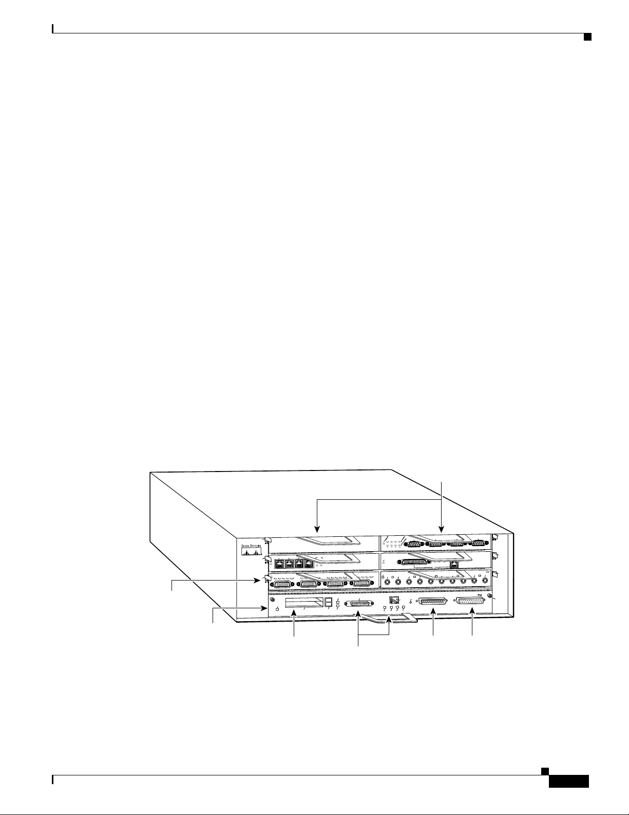
document is provided by components within the casing. Cisco 7206 VXR routers have six slots for port
adapters, one slot for an input/output (I/O) controller, and one slot for a network processing engine or
network services engine.
Figure 1 The 7206 VXR NPE-400 Router
5
3
2
1
Port adapter
lever
I/O controller
Cisco 7200
Series
0
ENABLED
3
EN
RC
RD
TC
TD
1
ENABLED
PC card slots
LINK
3
1
2
0
CD
LB
RC
RD
TC
TD
CD
LB
PCMCIA
TD
CD
LB
RC
RD
TC
TD
SLOT 1
EJECT
SLOT 0
Optional Fast Ethernet port
(MII receptacle and RJ-45 receptacle)
TC
FE MII
ETHERNET 10BT
FAST SERIAL
RC
RD
Port adapters
TOKEN RING
6
3
2
1
0
T
E
N
R
E
H
T
E
T
S
A
F
5
K
4
N
J
II
I
R
L
X
X
T
R
1
ESET
R
U
CP
Auxiliary
M
0
X
X
X
R
T
R
2
FAST ETHERNET INPUT/OUTPUT CONTROLLER
port
X
T
3
Console
port
ENABLED
N
E
CD
LB
X
X
T
R
0
RJ-45
MII
RJ45
RJ45
EN
OK
EN
1O PWR
LINK
ETHERNET-10BFL
X
R
4
TX
2
4
0
H5997
Cisco 7206 VXR NPE-400 uses an RM7000 microprocessor that operates at an internal clock speed of
350 MHz. The NPE-400 uses SDRAM for storing all packets received or sent from network interfaces.
The SDRAM memory array in the system allows concurrent access by port adapters and the processor.
Cisco 7206 VXR Router with ISA Security Policy
3
Page 4
The 7206 VXR NPE-400 Router
The NPE-400 has three levels of cache: a primary and a secondary cache that are internal to the
microprocessor, and a tertiary 4-MB external cache that provides additional high-speed storage for data
and instructions.
Cisco 7206 VXR routers come equipped with one 280W AC-input power supply. (A 280W DC-input
power supply option is available.) A power supply filler plate is installed over the second power supply
bay. A fully configured Cisco 7206 VXR router operates with only one installed power supply; however,
a second, optional power supply of the same type provides hot-swappable, load-sharing, redundant
power.
Module Interfaces
Input/Output Controller
The interfaces for the router are located on the front panel Input/Output (I/O) Controller, with the
exception of the power switch and power plug. The module has two Fast Ethernet (10/100 RJ-45)
connectors for data transfers in and out. The module also has two other RJ-45 connectors for a console
terminal for local system access and an auxiliary port for remote system access or dial backup using a
modem.
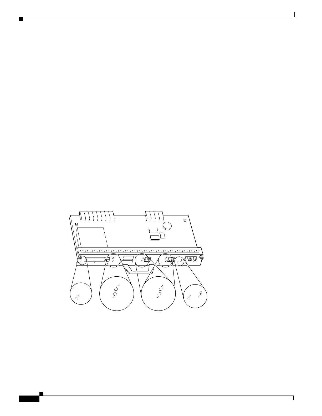
Figure 2 shows the front panel LEDs, which provide overall status of the router operation. The front
panel displays whether or not the router is booted, if the redundant power is attached and operational,
and overall activity/link status.
Figure 2 I/O Controller
C7200-I/O-2FE/E
ENABLED
ENABLED
SLOT 1
SLOT 0
EJECT
PCMCIA
SLOT 1
SLOT 0
LINK
FE/E 0
100 Mbps
100 Mbps
DUAL FAST ETHERNET INPUT/OUTPUT CONTROLLER
LINK
IO PW
FE/E 1
100 Mbps
LINK
R
OK
CPU
AUX
RESET
CONSOLE
IO PWR
OK
CPU
RESET
33444
Table 1 provides detailed information conveyed by the LEDs on the front panel of the I/O Controller.
Cisco 7206 VXR Router with ISA Security Policy
4
Page 5

The 7206 VXR NPE-400 Router
.
Table 1 Front Panel LEDs and Descriptions
LED Indication Description
Enabled Green Indicates that the network processing engine or network
services engine and the I/O controller are enabled for
operation by the system; however, it does not mean that the
Fast Ethernet port on the I/O controller is functional or
enabled. This LED goes on during a successful router boot
and remains on during normal operation of the router.
IO POWER OK Amber Indicates that the I/O controller is on and receiving DC power
from the router midplane. This LED comes on during a
successful router boot and remains on during normal
operation of the router.
Off Powered off or failed.
Slot 0
Slot 1
Green These LEDs indicate which PC Card slot is in use by coming
on when either slot is being accessed by the system. These
LEDs remain off during normal operation of the router.
Link Green Indicates that the Ethernet RJ-45 receptacle has established a
valid link with the network.
Off This LED remains off during normal operation of the router
unless there is an incoming carrier signal
100 Mbps Green Indicates that the port is configured for 100-Mbps operation
(speed 100), or if configured for autonegotiation (speed
auto), the port has detected a valid link at 100 Mbps.
Off If the port is configured for 10-Mbps operation, or if it is
configured for autonegotiation and the port has detected a
valid link at 10 Mbps, the LED remains off.
All of these physical interfaces are separated into the logical interfaces from FIPS as described in
Table 3.
Integrated Service Adapter
The ISA is a single-width service adapter. It provides high-performance, hardware-assisted tunneling
and encryption services suitable for VPN applications. The ISA off-loads IPSec and MPPE processing
from the main processor of the Cisco 7200 series router, thus freeing resources on the network processor
engine.
The ISA has one enabled LED and two status LEDs. After system initialization, the enabled LED goes
on to indicate that the ISA has been enabled for operation. If the initialization fails for any reason, the
enabled LED does not go on.
Figure 3 shows the LEDs for the ISA Crypto Card with one enabled LED and two status LEDs.
Cisco 7206 VXR Router with ISA Security Policy
5
Page 6

The 7206 VXR NPE-400 Router
Figure 3 LEDs for ISA Crypto Card
ENCRYPT/COMP
ENABLE
BOOT
ERROR
SA-ISA
17607
Refer to Ta b le 2 for further description of the ISA LEDs
Table 2 ISA LEDs and Descriptions
LED Indication Description
ENABLED Green Indicates the ISA is powered up. After system initialization,
the enabled LED goes on to indicate that power is received
and that the ISA is enabled for operation. All the following
conditions must be met before the enabled LED goes on:
• The ISA is correctly connected to the backplane and
receiving power.
• The system bus recognizes the ISA.
If either of these conditions is not met, or if the router
initialization fails, the enabled LED does not go on.
BOOT Amber Indicates the ISA is booting. This amber LED remains on
while the ISA is in the boot process or when a packet is being
encrypted or decrypted.
Pulse Amber Indicates the ISA is operating. After successfully booting, the
boot LED pulses in a "heartbeat" pattern to indicate that the
ISA is operating. As crypto traffic increases, the nominal
level of this LED increases in proportion to the traffic level.
ERROR Amber Indicates an error has occurred. This amber LED goes on to
indicate that an error was found in either the encryption
function or the compression function. It is normally off.
All of these physical interfaces are separated into the logical interfaces from FIPS as described in
Table 3.
Cisco 7206 VXR Router with ISA Security Policy
6
Page 7

Table 3 FIPS 140-1 Logical Interfaces
Router Physical Interface FIPS 140-1 Logical Interface
10/100BASE-TX LAN Port
Data Input Interface
Port Adapter Interface Service
Module Interface
Console Port
Auxiliary Port*
PCMCIA Slot*
10/100BASE-TX LAN Port
Data Output Interface
Port Adapter Interface Service
Module Interface
Console Port
Auxiliary Port*
PCMCIA Slot*
Power Switch
Control Input Interface
Console Port
The 7206 VXR NPE-400 Router
Auxiliary Port*
10/100BASE-TX LAN Port
LEDs
Pwr LED
Sys Rdy LED
Console Port
Auxiliary Port*
Power Plug Power Interface
* Disabled in FIPS mode. See the “Secure Operation of the Cisco 7206 VXR NPE-400 Router”section in this document for more
information.
In addition to the built-in interfaces, the router also has additional port adapters that can optionally be
placed in an available slot. These port adapters have many embodiments, including multiple Ethernet,
token ring, and modem cards to handle frame relay, ATM, and ISDN connections.
Roles and Services
There are two main roles in the router (as required by FIPS 140-1) that operators can assume: crypto
officer or administrator role and user role. The administrator of the router assumes the crypto officer role
in order to configure and maintain the router using crypto officer services, while the users exercise only
the basic user services.
Status Output Interface
Cisco 7206 VXR Router with ISA Security Policy
7
Page 8

The 7206 VXR NPE-400 Router
Cryptographic Officer Services
During initial configuration of the router, a cryptographic officer (crypto officer) password (the “enable”
password) is defined and all management services are available from this role. The crypto officer
connects to the router through the console port through the terminal program. A crypto officer can assign
permission to access the crypto officer role to additional accounts, thereby creating additional crypto
officers.
At the highest level, crypto officer services include the following:
• Configure the router: define network interfaces and settings, create command aliases, set the
protocols the router will support, enable interfaces and network services, set system date and time,
and load authentication information.
• Define rules and filters: create packet filters that are applied to user data streams on each interface.
Each filter consists of a set of rules, which define a set of packets to permit or deny based on
characteristics such as protocol ID, addresses, ports, TCP connection establishment, or packet
direction.
• Status functions: view the router configuration, routing tables, and active sessions; view SNMP MIB
II statistics, health, temperature, memory status, voltage, and packet statistics; review accounting
logs, and view physical interface status.
• Manage the router: log off users, shut down or reload the router, manually back up router
configurations, view complete configurations, manager user rights, and restore router
configurations.
• Set encryption/bypass: set up the configuration tables for IP tunneling. Set keys and algorithms to
be used for each IP range or allow plaintext packets to be set from specified IP addresses.
• Change port adapters: insert and remove adapters in port adapter slots as described in the “Initial
User Services
A user enters the system by accessing the console port with a terminal program. The IOS prompts the
user for their password. If it matches the plaintext password stored in IOS memory, the user is allowed
entry to the IOS executive program. At the highest level, user services include the following:
• ·Status Functions: view state of interfaces, state of layer 2 protocols, version of IOS currently
• Network Functions: connect to other network devices through outgoing telnet or PPP, and initiate
• Terminal Functions: adjust the terminal session (that is, lock the terminal and adjust flow control)
• ·Directory Services: display directory of files kept in flash memory
Physical Security
The router is entirely encased by a thick steel chassis. The front of the router provides 4 port adapter
slots, on-board LAN connectors, PC Card slots, and Console/Auxiliary connectors. The power cable
connection, a power switch, and the access to the Network Processing Engine are at the rear of the router.
Setup” section on page 11 in this document.
running
diagnostic network services (for example, ping or mtrace)
Cisco 7206 VXR Router with ISA Security Policy
8
Page 9

The 7206 VXR NPE-400 Router
Once the router has been configured to meet FIPS 140-1 Level 2 requirements, the router cannot be
accessed without signs of tampering. To seal the system, apply serialized tamper-evidence labels as
follows:
• Clean the cover of any grease, dirt, or oil before applying the tamper evidence labels. Alcohol-based
cleaning pads are recommended for this purpose. The ambient air must be above 10C, otherwise the
labels may not properly cure.
• The tamper evidence label should be placed so that the one half of the label covers the enclosure and
the other half covers the 7206 VXR NPE-400 Input/Output Controller.
• The tamper evidence label should be placed over the Flash PC Card slots on the Input/Output
Controller.
• The tamper evidence label should be placed so that one half of the label covers the enclosure and
the other half covers the port adapter slot 1.
• The tamper evidence label should be placed so that one half of the label covers the enclosure and
the other half covers the port adapter slot 2.
• The tamper evidence label should be placed so that one half of the label covers the enclosure and
the other half covers the port adapter slot 3.
• The tamper evidence label should be placed so that one half of the label covers the enclosure and
the other half covers the port adapter slot 4.
• The tamper evidence label should be placed so that one half of the label covers the enclosure and
the other half covers the port adapter slot 5.
• The tamper evidence label should be placed so that one half of the label covers the enclosure and
the other half covers the port adapter slot 6.
• The tamper evidence label should be placed so that one half of the label covers the enclosure and
the other half covers the network processing engine.
• The tamper evidence label should be placed so that one half of the label covers the enclosure and
the other half covers the power supply plate.
• The tamper evidence label should be placed so that one half of the label covers the enclosure and
the other half covers the redundant power supply plate.
The labels completely cure within five minutes.
Cisco 7206 VXR Router with ISA Security Policy
9
Page 10

The 7206 VXR NPE-400 Router
Figure 4 shows the tamper evidence label placements.
Figure 4 Tamper Evidence Label Placement
Port adapter
lever
I/O controller
Blank port adapter
5
0
ENABLED
3
EN
RC
RD
TC
TD
1
Cisco 7200
Series VXR
ENABLED
PC Card slots
3
2
1
LINK
3
1
2
0
TC
TD
CD
LB
RC
RD
TC
TD
CD
LB
EJECT
PCMCIA
SLOT 0
ETHERNET 10BT
ENABLED
IAL
ST SER
FA
N
E
CD
LB
RC
X
RD
TC
TD
CD
LB
RC
RD
SLOT 1
R
0
FE MII
MII
RJ45
RJ45
EN
EN
LINK
Optional Fast Ethernet port
(MII receptacle and RJ-45 receptacle)
Port adapters
0
X
X
R
T
1
T
ESE
R
5
PU
C
J-4
R
OK
1O PWR
Auxiliary
1
K
I
I
IN
L
M
0
X
X
X
T
R
T
2
FAST ETHERNET INPUT/OUTPUT CONTROLLER
port
5
4
J
R
X
R
TOKEN RING
2
T
S
A
F
ETHERNET-10BFL
X
X
R
T
3
Console
port
6
3
T
E
N
R
E
H
T
E
4
X
T
2
4
0
61228
Chassis
grounding
receptacles
Power supply
filler plate
Network processing engine
or network services engine
AC-input
receptacle
AC-input
power supply
NETW
ORK PROCESSING ENGINE-150
Internal fans
61229
Power switch
The tamper evidence seals are produced from a special thin gauge vinyl with self-adhesive backing. Any
attempt to remove port adapters or service modules will damage the tamper evidence seals or the painted
surface and metal of the module cover. Since the tamper evidence labels have nonrepeated serial
numbers, the labels can be inspected for damage and compared against the applied serial numbers to
verify that the module has not been tampered with. Tamper evidence labels can also be inspected for
signs of tampering, which include the following: curled corners, bubbling, crinkling, rips, tears, and
slices. The word “Opened” can appear if the label was peeled back.
10
Note The Cisco 7206 router supports the following FIPS-approved algorithms: DES, 3DES, and SHA-1.
These algorithms received certification numbers 74, 17, and 26 respectively.
Cisco 7206 VXR Router with ISA Security Policy
Page 11

Cryptographic Key Management
The router securely administers both cryptographic keys and other critical security parameters such as
passwords. The tamper evidence seals provide physical protection for all keys. Keys are also password
protected and can be zeroized by the crypto officer. Keys are exchanged manually and entered
electronically via manual key exchange or Internet Key Exchange (IKE).
Self-Tests
In order to prevent any secure data from being released, it is important to test the cryptographic
components of a security module to insure all components are functioning correctly. The router includes
an array of self-tests that are run during startup and periodically during operations. The self-test run at
power-up includes a cryptographic known answer test (KAT) on the FIPS-approved cryptographic
algorithms (DES, 3DES), on the message digest (SHA-1), and on the Diffie-Hellman algorithm. Also
performed at startup are software integrity test using an EDC, and a set of Statistical Random Number
Generator (RNG) tests. The following tests are also run periodically or conditionally: a bypass mode test
performed conditionally prior to executing IPSec, a software load test for upgrades, and the continuous
random number generator test. If any of these self-tests fail, the router transitions into an error state.
Within the error state, all secure data transmission is halted and the router outputs status information
indicating the failure.
Secure Operation of the Cisco 7206 VXR NPE-400 Router
Secure Operation of the Cisco 7206 VXR NPE-400 Router
Cisco 7206 VXR NPE-400 router meets all the Level 2 requirements for FIPS 140-1. Follow the setting
instructions provided below to place the module in FIPS mode. Operating this router without
maintaining the following settings will remove the module from the FIPS approved mode of operation.
Initial Setup
• The crypto officer must apply tamper evidence labels as described in the “Physical Security” section
of this document. The crypto officer must securely store tamper evidence labels before use, and any
tamper evidence labels not used should also be stored securely.
• Only a crypto officer can add and remove port adapters. When removing the tamper evidence label,
the crypto officer should remove the entire label from the router and clean the cover of any grease,
dirt, or oil with an alcohol-based cleaning pad. The crypto officer must reapply tamper evidence
labels on the router as described in the “Physical Security” section in this document.
System Initialization and Configuration
• The crypto officer must perform the initial configuration. The IOS version shipped with the router,
version 12.1(9)E, is the only allowable image. No other image can be loaded.
• The value of the boot field must be 0x0101 (the factory default). This setting disables the break from
the console to the ROM monitor and automatically boots the IOS image. From the configure
terminal command line, the crypto officer enters the following syntax:
config-register 0x0101
Cisco 7206 VXR Router with ISA Security Policy
11
Page 12

Secure Operation of the Cisco 7206 VXR NPE-400 Router
• The crypto officer must create the “enable” password for the crypto officer role. The password must
be at least 8 characters and is entered when the crypto officer first engages the enable command.
The crypto officer enters the following syntax at the “#” prompt:
enable secret [PASSWOR D]
• The crypto officer must always assign passwords (of at least 8 characters) to users. Identification
and authentication of the console port is required for users. From the configure terminal command
line, the crypto officer enters the following syntax:
line con 0
password [PASS WO RD ]
login local
• The crypto officer shall only assign users to a privilege level 1 (the default).
• The crypto officer shall not assign a command to any privilege level other than its default.
• The PCMCIA Flash memory card slot is not configured in FIPS mode. Its use is restricted via tamper
evidence labels. See the “Physical Security” section for more details.
Non FIPS-Approved Algorithms
• The following algorithms are not FIPS approved and should be disabled:
–
RSA for encryption
–
MD-5 for signing
–
AH-SHA-HMAC
–
ESP-SHA-HMAC
–
HMAC SHA-1
Protocols
• The following network services affect the security data items and must not be configured: NTP,
TACACS+, RADIUS, Kerberos.
• SNMP v3 over a secure IPSec tunnel can be employed for authenticated, secure SNMP Gets and
Sets. Since SNMP v2C uses community strings for authentication, only gets are allowed under
SNMP v2C.
Remote Access
• Auxiliary terminal services must be disabled, except for the console. The following configuration
disables login services on the auxiliary console line.
12
line aux 0
no exec
Cisco 7206 VXR Router with ISA Security Policy
Page 13

• Telnet access to the module is only allowed via a secure IPSec tunnel between the remote system
and the module. The crypto officer must configure the module so that any remote connections via
telnet are secured through IPSec.
Obtaining Documentation
The following sections provide sources for obtaining documentation from Cisco Systems.
World Wide Web
You can access the most current Cisco documentation on the World Wide Web at the following sites:
• http://www.cisco.com
• http://www-china.cisco.com
• http://www-europe.cisco.com
Obtaining Documentation
Documentation CD-ROM
Cisco documentation and additional literature are available in a CD-ROM package, which ships
with your product. The Documentation CD-ROM is updated monthly and can be more current than
printed documentation. The CD-ROM package is available as a single unit or as an annual subscription.
Ordering Documentation
Cisco documentation is available in the following ways:
• Registered Cisco Direct Customers can order Cisco Product documentation from the Networking
Products MarketPlace:
http://www.cisco.com/cgi-bin/order/order_root.pl
• Registered Cisco.com users can order the Documentation CD-ROM through the online Subscription
Store:
http://www.cisco.com/go/subscription
• Nonregistered Cisco.com users can order documentation through a local account representative by
calling Cisco corporate headquarters (California, USA) at 408 526-7208 or, in North America, by
calling 800 553-NETS(6387).
Documentation Feedback
If you are reading Cisco product documentation on the World Wide Web, you can submit technical
comments electronically. Click Feedback in the toolbar and select Documentation. After you complete
the form, click Submit to send it to Cisco.
You can e-mail your comments to bug-doc@cisco.com.
Cisco 7206 VXR Router with ISA Security Policy
13
Page 14

Obtaining Technical Assistance
To submit your comments by mail, use the response card behind the front cover of your document, or
write to the following address:
Attn Document Resource Connection
Cisco Systems, Inc.
170 West Tasman Drive
San Jose, CA 95134-9883
We appreciate your comments.
Obtaining Technical Assistance
Cisco provides Cisco.com as a starting point for all technical assistance. Customers and partners can
obtain documentation, troubleshooting tips, and sample configurations from online tools. For Cisco.com
registered users, additional troubleshooting tools are available from the TAC website.
Cisco.com
Cisco.com is the foundation of a suite of interactive, networked services that provides immediate, open
access to Cisco information and resources at anytime, from anywhere in the world. This highly
integrated Internet application is a powerful, easy-to-use tool for doing business with Cisco.
Cisco.com provides a broad range of features and services to help customers and partners streamline
business processes and improve productivity. Through Cisco.com, you can find information about Cisco
and our networking solutions, services, and programs. In addition, you can resolve technical issues with
online technical support, download and test software packages, and order Cisco learning materials and
merchandise. Valuable online skill assessment, training, and certification programs are also available.
Customers and partners can self-register on Cisco.com to obtain additional personalized information and
services. Registered users can order products, check on the status of an order, access technical support,
and view benefits specific to their relationships with Cisco.
To access Cisco.com, go to the following website:
http://www.cisco.com
Technical Assistance Center
The Cisco TAC website is available to all customers who need technical assistance with a Cisco product
or technology that is under warranty or covered by a maintenance contract.
Contacting TAC by Using the Cisco TAC Website
If you have a priority level 3 (P3) or priority level 4 (P4) problem, contact TAC by going to the TAC
website:
http://www.cisco.com/tac
14
Cisco 7206 VXR Router with ISA Security Policy
Page 15

P3 and P4 level problems are defined as follows:
• P3—Your network performance is degraded. Network functionality is noticeably impaired, but most
business operations continue.
• P4—You need information or assistance on Cisco product capabilities, product installation, or basic
product configuration.
In each of the above cases, use the Cisco TAC website to quickly find answers to your questions.
To register for Cisco.com, go to the following website:
http://www.cisco.com/register/
If you cannot resolve your technical issue by using the TAC online resources, Cisco.com registered users
can open a case online by using the TAC Case Open tool at the following website:
http://www.cisco.com/tac/caseopen
Contacting TAC by Telephone
If you have a priority level 1 (P1) or priority level 2 (P2) problem, contact TAC by telephone and
immediately open a case. To obtain a directory of toll-free numbers for your country, go to the following
website:
http://www.cisco.com/warp/public/687/Directory/DirTAC.shtml
P1 and P2 level problems are defined as follows:
Obtaining Technical Assistance
• P1—Your production network is down, causing a critical impact to business operations if service is
not restored quickly. No workaround is available.
• P2—Your production network is severely degraded, affecting significant aspects of your business
operations. No workaround is available.
AccessPath, AtmDirector, Browse with Me, CCIP, CCSI, CD-PAC, CiscoLink, the Cisco Powered Network logo, Cisco Systems Networking
Academy, the Cisco Systems Networking Academy logo, Fast Step, Follow Me Browsing, FormShare, FrameShare, GigaStack, IGX, Internet
Quotient, IP/VC, iQ Breakthrough, iQ Expertise, iQ FastTrack, the iQ Logo, iQ Net Readiness Scorecard, MGX, the Networkers logo, Packet,
RateMUX, ScriptBuilder, ScriptShare, SlideCast, SMARTnet, TransPath, Unity, Voice LAN, Wavelength Router, and WebViewer are trademarks
of Cisco Systems, Inc.; Changing the Way We Work, Live, Play, and Learn, Discover All That’s Possible, and Empowering the Internet Generation,
are service marks of Cisco Systems, Inc.; and Aironet, ASIST, BPX, Catalyst, CCDA, CCDP, CCIE, CCNA, CCNP, Cisco, the Cisco Certified
Internetwork Expert logo, Cisco IOS, the Cisco IOS logo, Cisco Press, Cisco Systems, Cisco Systems Capital, the Cisco Systems logo,
Enterprise/Solver, EtherChannel, EtherSwitch, FastHub, FastSwitch, IOS, IP/TV, LightStream, MICA, Network Registrar, PIX, Post-Routing,
Pre-Routing, Registrar, StrataView Plus, Stratm, SwitchProbe, TeleRouter, and VCO are registered trademarks of Cisco Systems, Inc. and/or its
affiliates in the U.S. and certain other countries.
By printing or making a copy of this document, the user agrees to use this information for product evaluation purposes only. Sale of this information
in whole or in part is not authorized by Cisco Systems.
All other trademarks mentioned in this document or Web site are the property of their respective owners. The use of the word partner does not imply
a partnership relationship between Cisco and any other company. (0108R)
Cisco 7206 VXR Router with ISA Security Policy
Copyright © 2001, Cisco Systems, Inc.
All rights reserved.
Cisco 7206 VXR Router with ISA Security Policy
15
Page 16

Obtaining Technical Assistance
16
Cisco 7206 VXR Router with ISA Security Policy
 Loading...