

Page 1

Cisco 7204 Installation and Configuration Guide
Corporate Headquarters
Cisco Systems, Inc.
170 West Tasman Drive
San Jose, CA 95134-1706
USA
http://www.cisco.com
Tel: 408 526-4000
800 553-NETS (6387)
Fax: 408 526-4100
Customer Order Num b er :
Text Part Number: OL-5101-02
Page 2

THE SPECIFICATIONS AND INFORMATION REGARDING THE PRODUCTS IN THIS M ANUAL ARE SUBJECT TO CHA NGE WITHOUT NO TICE. ALL
STATEMENTS, INFORMATION, AND RECOMMENDATIONS IN THIS MANUAL ARE BELIEVED TO BE ACCURATE BUT ARE PRESENTED WITHOUT
WARRANTY OF ANY KIND, EXPRESS OR IMPLIED. USERS MUST TAKE FULL RESPONSI BILITY FOR THEIR APPLICA TION OF ANY PRODUCT S.
THE SOFTWARE LICENSE AND LIMITED WARRANTY FOR THE ACCOMPANYING PRODUCT ARE SET FORT H IN THE INFORMATION PACKET T HAT
SHIPPED WITH THE PRODUCT AND ARE INCORPORATED HEREIN BY THIS REFERENCE. IF YOU ARE UNABLE TO LOCATE THE SOFTWARE LICENSE
OR LIMITED WARRANTY, CONTACT YOUR CISCO REPRESENTATIVE FOR A COPY.
The following information is for FCC compliance of Class A devices: This equipment has been tested and found to comply with the limits for a Class A digital device, pursuant
to part 15 of the FCC rules. These limits are designed to provide reasonable protection against harmful interference when the equipment is operated in a commercial
environment. This equipment generates, uses, and can radiate radio-frequency energy and, if not installed and used in accor dance with the instruction manual, may cause
harmful interference to radio communications. Operation of this equipment in a residential area is likely to cause harmful interference, in which case users will be required
to correct the interference at their own expense.
The following information is for FCC compliance of Class B devices: The equipment described in this manual generates and may radiate radio-frequency ener gy. If it is not
installed in accordance with Cisco’s installation instructions, it may cause interference with radio and television reception. This equipment has been tested and found to
comply with the limits for a Class B digital device in accordance with the specifications in part 15 of the FCC rules. These specifications are designed to provide reasonable
protection against such interference in a residential installation. However, there is no guarantee that interference will not occur in a particular installation.
Modifying the equipment without Cisc o’s writ ten author ization m ay resul t in the equi pment no lo nger comp lyi ng with FCC requi rements for Class A or Class B digital
devices. In that event, your right to use the equ ipment may be limit ed by FCC regul ations , and you may be requir ed to correct a ny interference to radio or television
communications at your own expense.
You can determine whether your equipment is causing interference by turning it off. If the interferen ce stops, it was probably caused by the Cis co equipm ent or one of its
peripheral devices. If the equipment causes interference to radio or television reception, try to correct the interference by using one or more of the following measures:
• Turn the television or radio antenna unt il the int erference st ops.
• Move the equipment to one side or the other of the televisio n or radi o.
• Move the equipment farther away from the te levision or radio.
• Plug the equipment into an outlet that is on a di fferent cir cuit from the televi sion o r radio. (That is, make certain th e equipment and the te levision or radio are on circuit s
controlled by different circuit breaker s or fuses.)
Modifications to this product no t author ized by Cis co Syst ems, Inc. coul d voi d the FCC appro val and ne gate your authorit y to op erate the pr oduct.
The Cisco implementation of TCP head er compressi on is an adap tation of a program developed by the Universi ty of Ca lifornia, Berk eley (UCB) as part of UCB ’s public
domain version of the UNIX operatin g system. All rights reserved . Copyri ght © 1981 , Rege nts of the Uni versity of Calif ornia.
NOTWITHSTANDING ANY OTHER WARRANTY HEREIN, ALL DOCUMENT FILES AND SOFTWARE OF THE SE SUPPLIERS ARE PROVIDED “AS IS” WITH
ALL FAULTS. CISCO AND THE ABOVE-NAMED SUPPLIERS DISCLAI M ALL WARRANTIE S, EXPRESSED OR IMPLIED, INCLUDING, WITHOUT
LIMITATION, THOSE OF MERCHANTABILITY, FITNESS FOR A PARTICULAR PURPOSE AND NO NINFRINGEM ENT OR ARISING FROM A COURS E OF
DEALING, USAGE, OR TRADE PRACTICE.
IN NO EVENT SHALL CISCO OR ITS SUPPLIERS BE LIABLE FOR ANY INDIRECT, SPECIAL, CONSEQUENTIAL, OR INCIDENTAL DAMAGES, INCLUDING ,
WITHOUT LIMITATION, LOST PROFITS OR LOSS OR DAMAGE TO DATA ARISING OUT OF THE USE OR INABILITY TO USE THIS MANUAL, EVEN IF CISCO
OR ITS SUPPLIERS HAVE BEEN ADVISED OF THE POSSIBILITY OF SUCH DAMAGE S.
CCSP, the Cisco Square Bridge logo, Cisco Unity, Follow Me Browsing, FormShare, and StackWise are trademarks of Cisco Systems, Inc.; Changing the Way W e Work, Live,
Play, and Learn, and iQuick Study are service marks of Cisco Systems, Inc.; and Aironet, ASIST, BPX, Catalyst, CCDA, CCDP, CCIE, CCIP, CCNA, CCNP, Cisco, the Cisco
Certified Internetwork Expert logo, Cisco IOS, Cisco Press, Cisco Systems, Cisco Systems Capital, the Cisco Systems logo, Empowering the Internet Generation,
Enterprise/Solver, EtherChannel, EtherFast, EtherSwitch, Fast Step, GigaDrive, GigaStack, HomeLink, Internet Quotient, IOS, IP/TV, iQ Expertise, the iQ logo, iQ Net Readiness
Scorecard, LightStream, Linksys, MeetingPlace, MGX, the Networkers logo, Networking Academy, Network Registrar, Packet, PIX, Post-Routing, Pre-Routing, ProConnect,
RateMUX, Registrar, ScriptShare, SlideCast, SMARTnet, StrataView Plus, SwitchProbe, TeleRouter, The Fastest Way to Increase Your Internet Quotient, TransPath, and VCO are
registered trademarks of Cisco Systems, Inc. and/or its affiliates in the United States and certain other countries.
All other trademarks mentioned in this document or Website are the property of their respective owners. The use of the word partner does not imply a partnership relationship
between Cisco and any other company. (0406R)
Cisco 7204 Installation an d Configuratio n Guide
Copyright © 1996, 1997, 1998 , 2004 Cisco System s, Inc. All r ights reserv ed. Print ed in USA.
Page 3

Preface vii
Document Objectives vii
Audience vii
Document Organization vii
Document Conventions viii
Safety Warnings ix
Terms and Acr on y m s xiii
Related Documentation xiii
Obtaining Documentation xiv
Cisco.com xiv
Ordering Documentation xiv
Documentation Feedback xiv
Obtaining Technical Assistance xv
Cisco Technical Support Website xv
Submitting a Service Request xv
Definitions of Service Request Severity xv
CONTENTS
CHAPTER
Obtaining Additional Publications and Information xvi
1 Product Overview 1-1
Physical Description 1-2
System Specifications 1-5
Software Requirements 1-6
Field-Repl a c ea ble Units 1-6
Network Processing Engine 1-6
Input/Output Controller 1-11
Port Adapters and Service Adapters 1-17
Power Supplies 1-18
Fan Tray 1-20
Chassis 1-21
PCMCIA Flash Disks and Flash Memory Cards 1-22
Rack-Mount and Cable-Management Kit 1-23
Functional Overview 1-23
Port Adapter Slot and Logical Interface Numbering 1-23
MAC Address 1-25
OL-5101-02
Cisco 7204 Installation and Configuration Guide
iii
Page 4

Contents
Online Insertion and Removal 1-25
Environmental Monitoring and Reporting Functions 1-26
Environmental Monitoring 1-26
Reporting Functions 1-28
Fan Failures 1-30
CHAPTER
2 Preparing for Installation 2-1
Safety Recommendations 2-1
Lifting Safely 2-2
Safety with Electricity 2-3
Preventing Electrostatic Discharge Damage 2-3
Site Requirements 2-4
AC and DC Power 2-4
Plant Wiring 2-4
Interferenc e Considerations 2-5
Distance Limitations and Interface Specifications 2-5
Equipment Racks 2-6
Site Environment 2-8
Preventive Sit e Configuration: Maintaining Normal Op eration 2-9
General Precautions 2-9
Power Considerations 2-10
Tools for Installation 2-10
Initial Configuration Information 2-11
Cisco 7204 Installation Checklist 2-11
CHAPTER
iv
Checking the Shipping Container Contents 2-13
Site Log 2-14
3 Installing the Cis co7204 3-1
Rack-Mounting the Cisco 720 4 3-1
Installing the Brackets on the Chassis 3-5
Installing the Brackets on the Front of the Chassis 3-6
Installing Brackets on the Rear of the Chassis 3-7
Installing the Chassis in the Rack 3-8
General Instal lation 3-9
Providing a Chassis Ground Connection for the Router Chassis 3-11
Connecting Port Adapter Cables 3-13
Connecting I/O Con troller Cables 3-13
Console and Auxiliary Port Connection Equipment 3-14
Cisco 7204 Installation and Configuration Guide
OL-5101-02
Page 5

Console Port Signals 3-15
Auxiliary Port S ignals 3-16
Fast Ethernet Con nection Equipment 3-16
Fast Ethernet MII C onnection Equipment 3-16
Fast Ethernet RJ- 45 Connection Equipment 3-18
Connecting Power 3-20
Connecting AC-Input Power 3-20
Connecting DC-Input Power 3-21
Starting the Cisco 7204 3-23
Contents
CHAPTER
CHAPTER
4 Performing a Basic Configuration of the Cisco7204 4-1
Using the Enable Sec ret and the Enable Password 4-1
Configuring the Cisco7204 4-2
Configuring the Cisco7204 Using AutoInstall 4-2
Configuring the Cisco7204 Manually Using the Setup Facility 4-4
Configuring Global Parameters 4-4
Configuring Interfaces 4-7
Configuring the Cisco7204 Using Configuration Mode 4-10
Saving Your Settings to NVRAM 4-10
Checking Your Settings and Reviewing Your Configuration Changes 4-11
Implementing Other Configuration Tasks 4-11
What Do I Do Now? 4-11
5 Troubleshooting the Installation 5-1
Troubleshooting Overview 5-2
Problem Solving with Subsystems 5-3
Identifying Startup Problems 5-3
Troubleshooting the Power Subsystem 5-5
CHAPTER
OL-5101-02
Troubleshooting the Processor Subsystem 5-6
Troubleshooting the I/O Controller 5-6
Troubleshooting the Network Processing Engine 5-6
Troubleshooti ng the Port Adapters and Service Adapters 5-7
Troubleshooti ng the Cooling Subsystem 5-7
6 Maintaining the Cisco7204 6-1
Viewing Your System Configuration 6-1
Replacing a Port Ad apter or Service Adapter 6-3
Installing and Remov ing a Flash Memory Card 6-7
Cisco 7204 Installation and Configuration Guide
v
Page 6

Contents
Formatting a New Flash Memor y Card 6-8
Copying a Bootable Image onto a Flash Memory Car d 6-9
Copying Bootable Images between Flash Memory Cards 6-11
Reformatting a Flash Memory Card 6-12
Replacing or Recovering a Lost Password 6-13
Overview of the Pass wo rd Recovery Procedure 6-14
Details of the Password Recovery Procedure 6-14
APPENDIX
APPENDIX
I
NDEX
A Industry-Standard Wi ring Plans A-1
B Configuration Register Information B-5
Configuratio n Bit Meanings B-5
Bits 0–3 B-6
Bit 6 B-7
Bit 7 B-7
Bit 8 B-8
Bit 10 and Bit 14 B-8
Bit 11 and Bit 12 B-8
Bit 13 B-8
Bit 15 B-9
Displaying the Co nfiguration Register While Running Cisco IOS B-9
Displaying the Configuration Register While Running ROM Monitor B-9
Setting the Configuration Register While Running Cisco IOS B-10
Setting the Configuration Register Whil e Running ROM Monitor B-10
vi
Cisco 7204 Installation and Configuration Guide
OL-5101-02
Page 7

Preface
This section explains the objectives, intended audience, and organization of the Cisco 7204 Installation
and Configuration Guide, and defines the conventions used to convey instructions and information.
Document Objectives
This installation guide explains the initial hardware installation and basic configuration procedures for
the Cisco 7204 ro ut er. It contains pro cedur e s for unpac king a nd in s tall ing t he rou ter h ar dware , star tin g
up the router , and creatin g a basic softwar e configur ation fil e. After complet ing the installatio n and basic
configuration proced ures covered in th is guide, you will th en use the a ppropr iate comp ani on
publications to m ore co mpl ete ly co nfigure you r system .
For comprehensive descriptions and examples of software configuration commands and the procedures
for implementing them, refer to the related software configuration and reference documentation listed in
the section “Related Documentation” section on page xiii.
Audience
To use this publication, you should be familiar with Cisco router hardware and cabling, electronic
circuitry and w iri ng pr act ice s, and pr ef er ab ly h ave experi en ce as an e l ect ron ic or ele c trom ec ha nic al
technician.
Document Organization
This installation guide is organized into the following chapters and appendix.
OL-5105-02
Cisco 7204 Installation and Configuration Guide
vii
Page 8

Preface
Document Conventions
Chapter Title Description
Chapter 1 Product Overview Chapter 1 describes the physical prope rties of
the Cisco 7204 a nd provide s a f unc tiona l
overview of the router.
Chapter 2 Preparing for Installation Chapter 2 is a preparatory chapter that
describe s safe ty consi dera tions, tools requir ed,
an overvie w of the installatio n, and procedures
you should perform before the actual
installation.
Chapter 3 Installing the Cisco 7204 Chapter 3 provides instructions for installing
the hardware and connecting the external
network interface cables.
Chapter 4 Performing a Basic Configurat ion of t he C isco 7204 Chapter 4 provides simple procedures for
completing a basic system configuration and
for checking and savi ng t his c onfigura tion t o
system memory.
Chapter 6 Troubleshooting the Installati on Chapter 5 provides gui deli nes for
troubleshooting the har dware insta llati on.
Chapter 5 Maintaining the Cisco 7204 Chapter 6 provides simple maintenance
procedures that yo u migh t need to pe rf orm
after you have installed your Cisco 72 04.
Appendix A Industry-Standard Wiring Plans Appendix A lists t he t elep hon e indu stry
color-code scheme for 25-pair wires including
the pin numbers.
Appendix B C onfiguration R egister I nf ormat ion Appendix B provides configuration register
information.
Document Conventions
This publication uses the following conventions:
• In screen displays, the sym bol ^ repr esents th e key labeled Control. For example, the key
combinatio n ^z means hold down the Control key while you press the z key.
Command descriptions use these conventions:
• Examples that c onta in system p rom pts denot e i nte ractive sessions , indi cat ing the com ma nds t hat
you should enter at the prom pt. The syst em promp t indic ates the cu rren t level of the EXEC
command inte rp re ter. For example , th e promp t
level, and the prompt
privileged level usually requires a password. Refer to the relate d software configu ration and
reference documentation listed in th e “Related Documentation” section on page xiii, for additional
information.
• Commands and keywords are in boldface font.
• Arguments for which you supply values are in italic font.
• Elements in sq uare br acket s ([ ]) a re op tiona l.
• Alternative but required keywords are grouped in braces ({ }) and separated by vertical bars (|).
Cisco 7204 Installation and Configuration Guide
viii
router> indicates that you shou ld be at the user
router# indicates that you should be at the privileged level. Access to the
OL-5105-02
Page 9

Preface
Examples use th ese conventions:
• Terminal sessions and sample console screen displays ar e in screen fo nt.
• Information you ent er is in b oldface sc reen f ont .
• Nonprinting char ac te rs, suc h as pa sswords, a re i n a ngle b racket s (< > ).
• Default responses to system prompts are in square brackets ([ ]).
• Exclamation poi nts (! ) at th e beginning of a lin e indi cat e a c om ment lin e.
Caution Means reader be care ful. In this situation, you might do something that could result in equipment
damage or loss of data.
Note Means reader take note. Notes contain helpful suggestions or references to materials not contained in
this manual.
Safety Warnings
Document Conventions
Warning
Waarschuwing
IMPORTANT SAFETY INSTRUCTIONS
This warning symbol means danger. You are in a situation that could cause bodily injury. Before you
work on any equipment, be aware of the hazards involved with electrical circuitry and be familiar
with standard practices for preventing accidents. To see translations of the warnings that appear in
this publication, refer to the translated safety warnings that accompanied this device.
Note: SAVE THESE INSTRUCTIONS
Note: This documentation is to be used in conjunction with t he specific product instal lat ion guide
that shipped with the product. Please refer to the Installation Guide, Configuration Guide, or other
enclosed additional documentation for further details.
BELANGRIJKE VEILIGHEIDSINS TRUC TIE S
Dit waarschuwingssymbool betekent gevaar. U verkeert in een situatie die lichamelijk letsel kan
veroorzaken. Voordat u aan enige apparatuur gaat werken, dient u zich bewust te zijn van de bij
elektrische schakelingen betrokken risico's en dient u op de hoogte te zijn van de standaard
praktijken om ongelukken te voorkomen. Voor een vertaling van de waarschuwingen die in deze
publicatie verschijnen, dient u de vertaalde veiligheidswaarschuwingen te raadplegen die bij dit
apparaat worden geleverd.
Opmerking BEWAAR DEZE INSTRUCTIES.
Opmerking Deze documentatie dient gebruikt te worden in combinatie met de
installatiehandleiding voor het specifieke product die bij het product wordt geleverd. Raadpleeg de
installatiehandleiding, configuratiehandleiding of andere verdere ingesloten documentatie voor
meer informatie.
OL-5105-02
Cisco 7204 Installation and Configuration Guide
ix
Page 10

Document Conventions
Preface
Varoitus
Attention
TÄRKEITÄ TURVALLISUUTEEN LIITTYVIÄ OHJEITA
Tämä varoitusmerkki merkitsee vaaraa. Olet tilanteessa, joka voi johtaa ruumiinvammaan. Ennen
kuin työskentelet minkään laitteiston parissa, ota selvää sähkökytkentöihin liittyvist ä vaaroista ja
tavanomaisista onnettomuuksien ehkäisykeinoista. Tässä asiakirjassa esitettyjen varoitusten
käännökset löydät laitteen mukana toimitetuista ohjeista.
Huomautus SÄILYTÄ NÄMÄ OHJEET
Huomautus Tämä asiakirja on tarkoitettu käytettäväksi yhdessä tuotteen mukana tulleen
asennusoppaan kanssa. Katso lisätietoja asennusoppaasta, kokoonpano-oppaasta ja muista
mukana toimitetuista asiakirjoista.
IMPORTANTES INFORMATIONS DE SÉCU RI TÉ
Ce symbole d'avertissement indique un danger . V ous vous trouvez dans un e situation pouvant causer
des blessures ou des dommages corporels. Avant de travailler sur un équipement, soyez conscient
des dangers posés par les circuits électriques et familiarisez-vous avec les procédures couramment
utilisées pour éviter les accidents. Pour prendre connaissance des traductions d'avertissements
figurant dans cette publication, consultez les consignes de sécurité traduites qui accompagnent cet
appareil.
Remarque CONSERVEZ CES INFORMATIONS
Remarque Cette documentation doit être utilisée avec le guide spécifique d'installati on du produit
qui accompagne ce dernier. Veuillez vous reporter au Guide d'installation, au Guide de
configuration, ou à toute autre documentation jointe pour de plus amples renseignements.
Warnung
WICHTIGE SI CHERHE ITSAN WEIS UNGEN
Dieses Warnsymbol bedeutet Gefahr. Sie befinden sich in einer Situation, die zu einer
Körperverletzung führen könnte. Bevor Sie mit der Arbeit an irgendeinem Gerät beginnen, seien Sie
sich der mit elektrischen Stromkreisen verbundenen Gefahren und der Standardpraktiken zur
Vermeidung von Unfällen bewusst. Übersetzungen der in dieser Veröffentlichung enthaltenen
Warnhinweise sind im Lieferumfang des Geräts enthalten.
Hinweis BEWAHREN SIE DIESE SICHERHEITSANWEISUNGEN AUF
Hinweis Di eses Handbuch ist zum Gebrauch in Verbindung mit dem Installationshandbuch für Ihr
Gerät bestimmt, das dem Gerät beiliegt. Entnehmen Sie bitte alle weiteren Informationen dem
Handbuch (Installations- oder Konfigurationshandbuch o. Ä.) für Ihr spezifisches Gerät.
Cisco 7204 Installation and Configuration Guide
x
OL-5105-02
Page 11

Preface
Document Conventions
Avvertenza
Advarsel
IMPORTANTI ISTRUZIONI SULLA SICUREZZA
Questo simbolo di avvertenza indica un pericolo. La situazione potrebbe causare infortuni alle
persone. Prima di intervenire su qualsiasi apparecchiatura, occorre essere al corrente dei pericoli
relativi ai circuiti elettrici e conoscere le procedure standard per la prevenzione di incidenti. Per le
traduzioni delle avvertenze riportate in questo documento, vedere le avvertenze di sicurezza che
accompagnano questo dispositivo.
Nota CONSERVARE QUESTE IS TRUZIONI
Nota La presente documentazione va usata congiuntamente alla guida di installazione specifica
spedita con il prodotto. Per maggiori informazioni, consultare la Guida all'installazione, la Guida
alla configurazione o altra documentazione acclusa.
VIKTIGE SIKKERHETSINSTRUKSJONER
Dette varselssymbolet betyr fare. Du befinner deg i en situasjon som kan forårsake personskade.
Før du utfører arbeid med utstyret, bør du være oppmerksom på farene som er forbundet med
elektriske kretssystemer, og du bør være kjent med vanlig praksis for å unngå ulykker. For å se
oversettelser av advarslene i denne publikasjonen, se de oversatte sikkerhetsvarslene som følger
med denne enheten.
Merk TA VARE PÅ DISSE INSTRUKSJONENE
Merk Denne dokumentasjonen skal brukes i forbindelse med den spesifikke
installasjonsveiledningen som fulgte med produktet. Vennligst se installasjonsveiledningen,
konfigureringsveiledningen eller annen vedlagt tilleggsdokumentasjon for detaljer.
Aviso
¡Advertencia!
INSTRUÇÕES IMPORTANTES DE SEGURANÇA
Este símbolo de aviso significa perigo. O utilizador encontra-se numa situação que poderá ser
causadora de lesões corporais. Antes de iniciar a utilização de qualquer equipamento, tenha em
atenção os perigos envolvidos no manuseamento de circuitos eléctricos e familiarize-se com as
práticas habituais de prevenção de acidentes. Para ver traduções dos avisos incluídos nesta
publicação, consulte os avisos de segurança traduzidos que acompanham este dispositivo.
Nota GUARDE ESTAS INSTRUÇÕES
Nota Esta documentação destina-se a ser utilizada em conjunto com o manual de instalação
incluído com o produto específico. Consulte o manual de instalação, o manual de configuração ou
outra documentação adicional inclusa, para obter mais informações.
INSTRUCCIONES IMPORTANTES DE SEGURIDAD
Este símbolo de aviso indica peligro. Existe riesgo para su integridad física. Antes de manipular
cualquier equipo, considere los riesgos de la corriente eléctrica y familiarícese con los
procedimientos estándar de prevención de accidentes. Vea las traducciones de las advertencias
que acompañan a este dispositivo.
Nota GUAR DE ESTAS INSTRUCCIONES
Nota Esta documentación está pensada para ser utilizada con la guía de instalación del producto
que lo acompaña. Si necesita más detalles, consulte la Guía de instalación, la Guía de
configuración o cualquier documentación adicional adjunta.
OL-5105-02
Cisco 7204 Installation and Configuration Guide
xi
Page 12
Document Conventions
Preface
Varning!
VIKTIGA SÄKERHETSANVISNINGAR
Denna varningssignal signalerar fara. Du befinner dig i en situation som kan leda till personskada.
Innan du utför arbete på någon utrustning måste du vara medveten om farorna med elkretsar och
känna till vanliga förfaranden för att förebygga olyckor. Se översättningarna av de
varningsmeddelanden som finns i denna publikation, och se de översatta säkerhetsvarningarna som
medföljer denna anordning.
OBS! SPARA DESSA ANVISNINGAR
OBS! Denna dokumentation ska användas i samband med den specifika
produktinstallationshandbok som medföljde produkten. Se installationshandboken,
konfigurationshandboken eller annan bifogad ytterligare dokumentation för närmare detaljer.
xii
Cisco 7204 Installation and Configuration Guide
OL-5105-02
Page 13

Preface
Terms and Acronyms
To fully understand the content of this installation and configuration guide, you should be familiar with
the following terms and acronyms:
• DCE—Data communic ation s equipme nt
• DMA—Direct memory ac cess
• DRAM—Dynamic random- acc ess memory
• DTE—Data terminal equipment
• EPROM—Erasable p rog ra mmab le re ad -on ly mem ory
• FRU—Field-replaceable unit (rou ter comp onents that do not requir e replace ment by a
Cisco-certified service provider)
• Gbps—Gigabi ts per secon d
• MB—Megabyte
• NVRAM—Nonvolatile random-access mem ory
• OIR—Online insertion and removal
• PCI—Periphera l compone nt interc onnect
Terms and Acronyms
• PCMCIA—Personal Compute r Memory Card Inter nationa l Associati on
• RFI—Radio f reque ncy i nte rf eren ce
• RISC—Reduced instruction set computing
• SIMM—Single in-line memory module
• SNMP—Simple Network Manage ment Protoc ol
• SRAM—Static random- acce ss memory
• TFTP—Trivial File Transfer Protocol
Related Documentation
Your Cisco 7204 router and th e Cisco IOS sof tware running on it contain exte nsive features and
functionality, which are documented in the following resources:
• Cisco 7200 Series R outers D o cume ntation R oad map at
http://www.cisco.com/univercd/cc/td/doc/product/core/720 0vx/ol3512 .htm f or a list of a ll Cisco
7200 series rout er s docu me nta tio n and tro uble shoo tin g to ol s and inf orm ati on .
• Cisco 7200 Series R outers P ort Ad apte r Doc ume ntati on Roadm ap at
http://www.cisco.com/univercd/cc/td/doc/product/core/720 0vx/ol3530 .htm f or a list of a ll Cisco
7200 series routers-sup ported port adapte r docum entati on.
• Cisco 7200 Series R outers Troubleshooting Documentat ion Ro admap at
http://www.cisco.com/univercd/cc/td/doc/product/core/720 0vx/ol3518 .htm for links to
troubleshooting tools, utilities, and Tech Notes.
OL-5105-02
Cisco 7204 Installation and Configuration Guide
xiii
Page 14

Obtaining Docume ntation
Obtaining Documentation
Cisco documentatio n and a dd ition al lite rat ure a r e available on Cisc o.co m. Cisc o al so provide s s everal
ways to obtain technical assista nce an d othe r techni cal re sour ces. Thes e secti ons explain how to obtain
technical information from Cisco Systems.
Cisco.com
You can access the most current Cisco documentation at this URL:
http://www.cisco.com/univercd/home/home.htm
You can access the Cisco website at this URL:
http://www.cisco.com
You can access international Cisco websites at this URL:
http://www.cisco.com/public/countries_languages.shtml
Preface
Ordering Documentation
You can find ins tr uct ions for or deri ng do cu me nta tio n at thi s URL:
http://www.cisco.com/univercd/cc/td/doc/es_inpck/pdi.htm
You can order Cisco documen tation i n these ways:
• Registered Cisco.com users (Cisco direct customers) can order Cisco product documentation from
the Ordering tool:
http://www.cisco.com/en/US/partner/ordering/index.shtml
• Nonregistered Cisco.co m u ser s can o rd er docum en tati on th rou gh a l oc al ac count r epre sen tative by
calling Cisco Systems Corporate Headquarters (California, USA) at 408 526-7208 or, elsewhere in
North America, by calling 800 553-NETS (6387).
Documentation Feedback
You can send com ments ab out tec hnical doc ument ation to bug-doc @cisco.c om.
You can submi t commen ts by using the re sponse car d (if pres ent) beh ind the front cover of your
document or by wri ting t o the fo llowing a ddress:
Cisco Systems
Attn: Customer Docume nt Ordering
170 West Tasman Drive
San Jose, CA 95134- 988 3
We appre ciat e your co mmen ts .
xiv
Cisco 7204 Installation and Configuration Guide
OL-5105-02
Page 15

Preface
Obtaining Technical Assistanc e
For all customers, partners, resellers, and distributors who h old valid Cisco serv ice contra cts, Cisco
Technical Support provides 24-hour-a-day, award-winning technic al assist anc e. T he C isco Technical
Support Website on Cisco.com features extensive online support resources. In addition, Cisco Technical
Assistance Center (TAC) engineers provide te leph one su ppor t. If y ou do n ot ho ld a valid Cisco se rvic e
contract, contact your reseller.
Cisco Technical Support Website
The Cisco Technical Support Website provides online docum ents a nd tools fo r tr oub lesho oti ng a nd
resolving technical issues with Cisco products and technologies. The website is available 24 hours a day,
365 days a yea r at thi s UR L:
http://www.cisco.com/techsupport
Access to all tools on the Cisco Technical Support Website requires a Cisco.com user ID and password.
If you have a valid service contract but do not have a user ID or password, you can register at this U R L:
http://tools.cisco.com/RPF/register/register.do
Obtaining Technical Assistance
Submitting a Service Request
Using the online TAC Service Request Tool is the fastest way to open S3 and S4 service requests. (S3
and S4 service requests are those in which your network is minimally impaired or for which you require
product information. ) After you desc ribe you r situation, the TAC Service Request Tool automatically
provides recommended solut ions. If yo ur issue is not resolved usin g the recomm ende d resource s, your
service request will be assigned to a Cisco TAC engineer. The TAC Service Request Tool is located at
this URL:
http://www.cisco.com/techsupport/servicerequest
For S1 or S2 service requests or if you do not have Internet access, contact the Cisco TAC b y telephone.
(S1 or S2 service requests are t hose in whic h your prod uction net work is down or severely degraded.)
Cisco TAC engineer s are a ssi gned im medi atel y t o S1 and S2 ser vice r eques ts to h elp k eep your bu sin ess
operations running smoothly.
To open a service request by telep hone, use one of the following number s:
Asia-Pacific: +61 2 8446 7411 (Australia : 1 800 805 227)
EMEA: +32 2 704 55 55
USA: 1 800 553 2447
For a complete list of Cisco TAC contacts, go to this URL:
http://www.cisco.com/techsupport/contacts
Definitions of Service Request Severity
OL-5105-02
To ensure that all service requests are reported in a standard format, Cisco has established severity
definitions.
Severity 1 (S1)—Your network is “down,” or there is a critical impact to your business operat ions. Yo u
and Cisco will commit all necessary resources around th e clock to resolve the situation.
Cisco 7204 Installation and Configuration Guide
xv
Page 16

Obtaining Additiona l Publications and Informatio n
Severity 2 (S2)—Operation of an exis ting n etwor k is severely degrad ed, o r s ignificant aspe c ts of yo ur
business operation are negatively affected by inadequate performance of Cisco products. You and Cisco
will commit full-time resources during normal business hours to resolve the situation.
Severity 3 (S3)—Operational performance of your network is impaired, but most business operations
remain functional. You and Cisco will commit resources during normal business hours to restore service
to satisfactory levels.
Severity 4 (S4)—You require information or assistance with Cisco product capabilities, installation, or
configuration. There is littl e or no effect on you r business operations.
Obtaining Additional Publications and Information
Information about Cisco products, technologies, and network solutions is available from various online
and printed sources.
• Cisco Marketplace provides a variety of Cisco books, reference guides, and logo merchandise. Visit
Cisco Marketplace, the company store, at this URL:
http://www.cisco.com/go/marketplace/
Preface
• The Cisco Product Catalog describes the networking products offered by Cisco Systems, as well as
ordering and custome r support ser vices. Ac cess the Cisc o Product Ca talog at this URL:
http://cisco.com/univercd/cc/td/doc/pcat/
• Cisco Press publishes a wide range of general networking , training and certif ication titles. Both ne w
and experienced users will benefit from these publications. For current Cisco Press titles and other
information, go to Cisco Press at this URL:
http://www.ciscopress.com
• Packet magazine is the Cisco System s techni cal user ma gazine for maximiz ing Intern et an d
networking investments. Each quar ter, Packet delivers coverage of t he l ate st ind ust ry t rend s,
technology breakthrough s, and Cisco product s and soluti ons, as well as networ k deployme nt and
troubleshooting t ips, configu ratio n exa mp les, cust om er c a se studie s, ce rtificat ion an d tr aini n g
information, and links to scores of in-depth online resources. You can access Packet maga zine at this
URL:
http://www.cisco.com/packet
• iQ Magazine is the quarterly pu bli cat ion fr om C isco System s desig ned t o hel p gr owing comp anies
learn how they can use tec hn ology to i n crea se revenue, stre a mline the ir business , and expand
services. The publication identifies the challenges facing these companies and the technologies to
help solve them, usin g rea l-worl d ca se st ud ies an d business st rategies t o he lp r eade rs make soun d
technology investment decisions. You can access iQ Magazin e at this URL :
http://www.cisco.com/go/iqmagazine
• Internet Protocol Journal is a quarterly journal published by Cisco Systems for engineeri ng
professionals involved in designing, developing, and ope ratin g p ubli c a nd pr ivate internets a nd
intranets. You can access the Internet Protocol Journal at this URL:
xvi
http://www.cisco.com/ipj
• Wo rld-cl ass networki ng traini ng is available from Cisco. You can view current offerings at
this URL:
http://www.cisco.com/en/US/learning/index.html
Cisco 7204 Installation and Configuration Guide
OL-5105-02
Page 17

CHAPTER
1
Product Overview
This chapter provides physical and fun ctional overviews of the Cisco 7204 router. It contains physical
descriptions of th e r oute r ha rdware an d m ajo r c om ponen t s, and f unc ti onal d esc ripti on s o f
hardware-related features. Descriptions and examples of software commands are included only when
they are necessary for rep lac ing, inst al ling , co nfigurin g, or m aint ai ning t he r oute r hardware .
The Cisco 7204 i s p art of the C isco 7200 series routers, wh ich co nsi sts of t he 2- slot Cisco 7202, 4-slot
Cisco 7204 and Cisco 7204VXR, and 6-slot Cisco 7206 and Cisco 7206VXR. The Cisco 7204 supports
multiprotocol, multimedia routing and bridging over a wide variety of LAN and WAN interface types.
Network interfaces reside on port adapters that provide the connection between the router’s three
Peripheral Compone nt I nte rconn ec t ( PCI) buses and exter nal net works. Th e Cisc o 7 204 has fou r s lot s
(slot 1 through slot 4) for the port adapters, one slot for an Input/Output (I/O) controller, and one slot for
a network processing engine. You can place the port adapters or service adapters in any of the four
available slots.
There are bays for up to two AC-input or DC- input power supplie s. The Ci sco 7 204 wil l operat e with
one power supply. While a second power supply i s n ot r equi red, it a llows loa d sha ring a nd i ncre ased
system availability.
OL-5101-02
Note The Ci sco 7204 does not sup por t a mi x ture of AC- and DC-i nput p ower.
The Cisco 7204 provide s the following features :
• Online insertion and removal (OIR)—Allows you to add, repl ace , or re move port a dap te rs wit ho ut
interrupting the syste m or enter ing any cons ole comm ands.
• Dual hot-swappable, load-sharing power supplies—Provide system power redundancy; if one power
supply or power source fails, the other power supply maintains system power without interruption.
Also, when one power supply is powered off and removed from the router, the second power supply
immediately takes o ver the router’s power requirements without interrupting normal operation of th e
router.
• Environmental monitoring and repo rting fun ctions —Allow you to maintain normal system
operation by resolving adverse environment al con dit ions befor e any lo ss of o pe ratio n.
• Downloadable software—Allows you to load new images into Flash memory remotely, without
having to physically acc ess t he Cisco 7204 router, for fast, rel iab le upg rade s.
Cisco 7204 Installation and Configuration Guide
1-1
Page 18
Physical Descriptio n
Physical Description
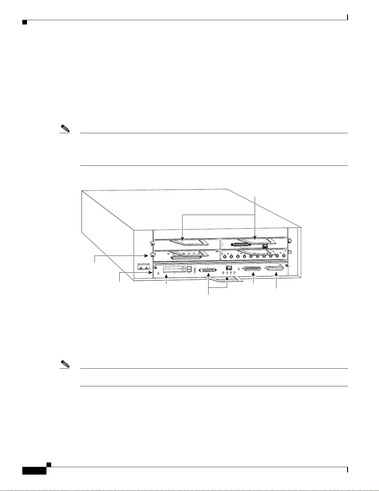
The front of the Cisco 7204 provides access to an I/O controll er and up to fo ur network interface port
adapters (see Figure 1-1). The I/O controller contains the following: a local console port for connecting
a data terminal (or data terminal equipment [DTE]) and an auxiliary port for connectin g a modem (or
other data communications equipment [DCE]) or other devices for configuring and managing the router;
two Personal Computer Memory Card International Association (PCMCIA) slots for Flash memory
cards; an option al Fast Et herne t p ort . T he Fast Ethe r net por t pr ovides a 100 -Mbps c onnec tio n to the
network.
Note The I/O controller is available with or without a Fast Ethernet port. The I/O controller with a Fast
Ethernet port is equi pped with eit her a sing le MII port or an MII port a nd an RJ-45 port (only one por t
can be used at a time). Although still supported by Cisco Systems, the I/O controller equipped with the
single MII port was discontinued as an order able produc t in May 1998.
Figure 1-1 Cisco 7204 Router—F ront View
Chapter 1 Product Overview
Port adapters
SERIES
Port adapter
lever
I/O controller
3
N
E
1
0
1
ENABLED
PCMCIA
PC Card slots
D
E
L
B
A
N
E
N
SERIAL-EIA/TIA-232
E
X
7
6
5
4
3
2
SLOT 1
EJECT
SLOT 0
R
0
FE MII
MII
RJ45
RJ45
EN
EN
LINK
Optional Fast Ethernet port
X
T
-
J
R
OK
1O PWR
5
4
X
X
T
R
1
T
E
S
E
R
U
P
C
Auxiliary
Cisco 7200
5
K
4
I
J
I
IN
R
L
M
0
X
X
X
R
T
R
2
FAST ETHERNET INPUT/OUTPUT CONTROLLER
port
E
T
S
A
F
T
E
N
R
E
H
T
E
X
X
R
T
4
3
Console
port
T
E
N
R
E
H
T
4
L
F
B
0
1
-
X
T
2
0
H7398
(MII receptacle and RJ-45 receptacle)
The port adapters installed in the Cisco 7204 are of the same type as those installed on the
second-generation V ersatile Interface Processors (VIP2s) in the Cisco 7500 series routers, in Cisco 7000
series routers using the 7000 Ser ies Route Swit ch Process or (RSP7000) and 7000 series Chassi s
Interface (RSP7000CI), and in the Cisco uBR72 00 series routers. T he port ada pters inst alled in the
Cisco 7204 support OIR. For an explanation of OIR, refer to the section “Online Insertion and Removal”
section on page 1-25.
Note The I/O controller does not support OIR. Y ou must power down the Cisco 7204 before removing the I/O
controller from the router.
Port adapter slots in the Cisco 7204 router are numbered from left to right, beginning with port adapter
slot 1 and continuing through port adapter slot 4. Port adapter sl ot 0 is the Fast Ethernet port on the I/O
controller (r efer to Figure 1-2).
1-2
Cisco 7204 Installation and Configuration Guide
OL-5101-02
Page 19
Chapter 1 Product Overview
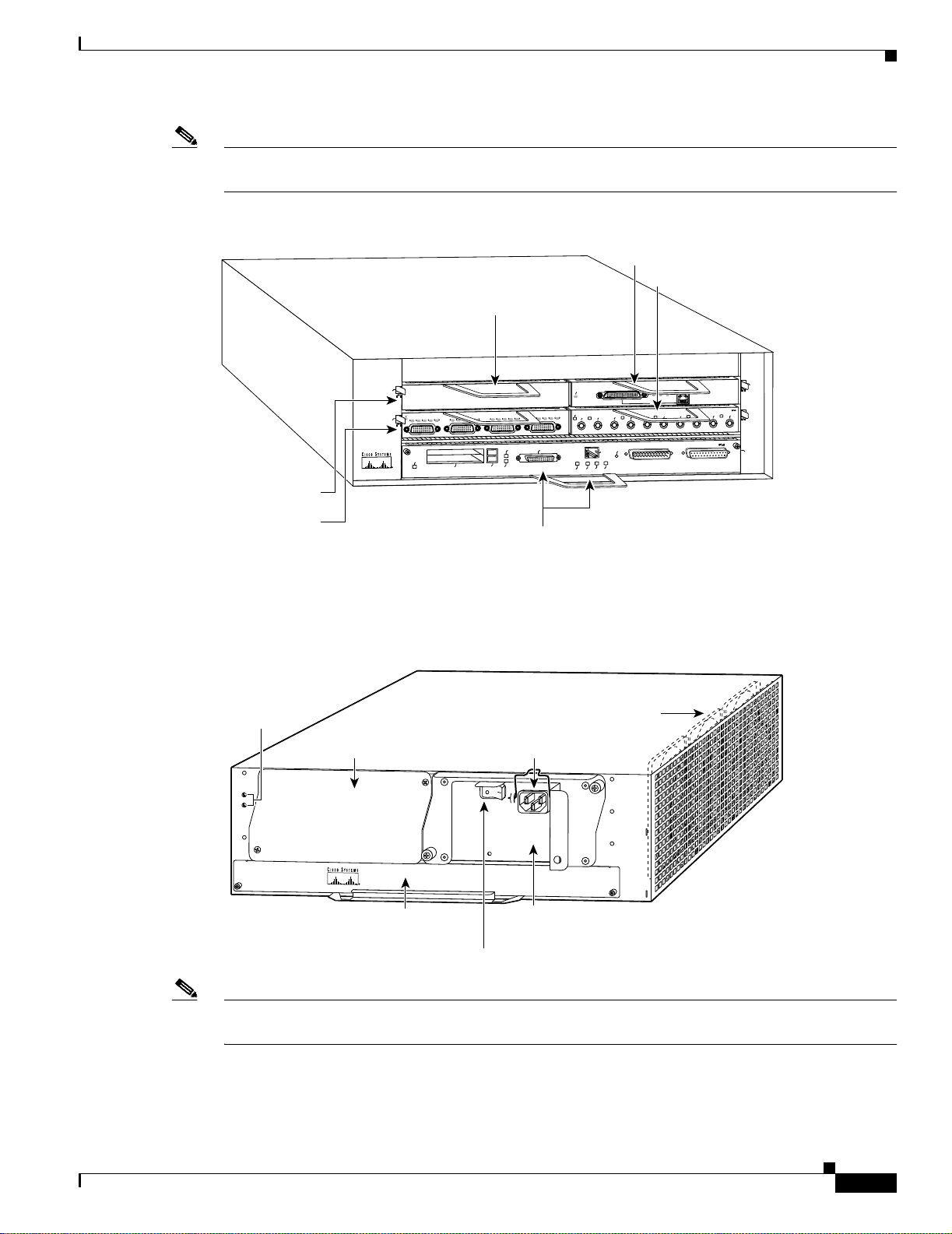
Note In Figure 1-1 and Figure 1- 2, a blank port adapter is installed in slot 3. To ensure adequate airflow across
the port adapters, each port adapter slot must be filled with either a port adapter or a blank port adapter.
Figure 1-2 Port Adapter Slot Numbering
Port adapter slot 3
Physical Description
Port adapter slot 4
Port adapter slot 2
Blank port adapter
SERIES
Cisco 7200
K
D
E
L
B
A
3
N
E
N
E
D
T
1
3
2
1
0
C
D
C
R
R
T
ENABLED
IN
L
3
1
2
0
C
D
D
C
B
D
C
D
D
B
C
L
PCMCIA
T
T
C
L
R
R
T
T
EJECT
SLOT 0
ETHERNET 10BT
ENABLED
L
A
I
R
E
S
T
S
A
F
N
E
D
C
B
D
C
D
D
C
B
D
R
R
SLOT 1
C
L
R
R
T
T
C
L
FE MII
X
X
X
R
T
R
1
0
E
S
E
R
U
5
4
P
-
C
J
R
MII
RJ45
RJ45
EN
OK
EN
1O PWR
LINK
0
X
X
R
T
T
FAST ETHERNET INPUT/OUTPUT CONTROLLER
5
K
4
J
II
IN
R
L
M
X
X
R
T
2
T
E
N
R
E
H
T
E
T
S
A
F
4
L
F
B
0
1
-
T
E
N
R
E
H
T
E
X
X
X
T
R
T
3
2
4
0
H7399
Port adapter slot 1
Port adapter slot 0
The rear of the Cisco 7204 router provides access to the network processing engine and up to two power
supplies (refer to Figure 1-3).
Figure 1-3 Cisco 7204 Router—Rear View
Chassis
grounding
receptacles
Power supply
filler plate
Network processing engine
or network services engine
Power switch
AC-input
receptacle
AC-input
power supply
N
E
T
W
O
R
K
P
R
O
Internal fans
C
E
S
S
IN
G
E
N
G
IN
E
-1
5
0
H6423
OL-5101-02
Note The net work process ing engi ne does not supp ort OIR. You must power down the Cisco 7 204 befo re
removing the network pr oces sin g engi ne fr om the r oute r.
The network processing engine has no external connectors or LEDs. There is a handle for removing and
installing the network processing en gine and two capti ve insta llation scre ws for securing it to the ch assis.
Cisco 7204 Installation and Configuration Guide
1-3
Page 20

Physical Descriptio n
Caution Do not mix power suppli es in t he Ci sco 7204. In dual power s upply ro ute r con figurati ons, b ot h power
Chapter 1 Product Overview
The Cisco 7204 router comes equipped with one 280W AC-input or one 280W DC-input power supply.
A fully configured Cisco 7204 router operates with only one installed power supply; however , a second,
optional power supply of the same type provides hot- swappable, load -sharin g, redunda nt power.
Figure 1-3 shows the re ar of a C isco 7204 router configu red w it h a si ngle AC-input power su pply. (A
power supply filler plate is installed over the second power supply bay.)
supplies must be of the same type (two AC-input power supplies or two DC-inpu t power supplies).
The power supply has the router’s main power switch and either an AC-input power receptacle or a
hardwired DC-input power cabl e (depend ing on the type of installe d power supply).
Adjacent to the power supply bays there are two chassis ground receptacles that provide a chassis ground
connection for ES D eq uipm en t or a two- hole g roundi ng lug ( refe r to Figu re 1 -3).
Three internal fans draw cooling air into chassis and across internal components to maintain an
acceptable operatin g temperature. (Refer to Figure 1-3.) The three fans are enclosed in a tray that is
located in the subchassis.
Caution To ensure the proper flow of cooling air across the internal components, make sure blank port adapters
are installed in unoccupied port adapter slot s, and power supply filler plates are installed in unoccupied
power supply bays.
The I/O controller, port adap ters, power suppli es, an d network proc essing engine slid e into thei r
respective chassis slots and connect directly to the router’s midplane; there are no internal cables to
connect. The midplane distributes DC power from the power supplies to the I/O controller, port adapters,
fan tray, and network processing engine.
The midplane also identifies OIR of the port adapters, bridges the PCI buses from the port adapters to
packet static random-access memory (SRAM) on the network processing engine, arbitrates traffic across
the PCI buses, and gene rates the c lock sign als for the por t ad ap ter s on ea ch PCI bus.
The Cisco 7204 op er ate s a s eit her a tab let op or r ack -mou nt ed u ni t. A ra c k-moun t kit is st anda rd
equipment included with all Cisco 7204 routers when they are shipped from the factory. The kit provides
the hardware needed to mo unt the ro uter in a sta ndard 19-inch eq uipment ra ck or a 2-p ost rack. Steps
for installing the Cisco 7204 router in an equipment rack are explained in Chap ter 3, “Installing the
Cisco 7204.” I f you a re no t rac k-mou nt ing you r C isco 7204, place it on a stur dy t able top or p lat fo rm.
A fully configured Cisco 7204, with two installed power supplies and all chassis slots filled, weighs
approximately 50 pounds (22.7 kilograms [kg]). For clearance requirements and rack-mount installation
considerations, refer to the section “Site Environment” in Chapter 2, “Preparing for Installation.”
1-4
Cisco 7204 Installation and Configuration Guide
OL-5101-02
Page 21

Chapter 1 Product Overview
Physical Description
System Specifications
Table 1-1 lists the Cisco 7204 router physical specifications and power requirements.
Table 1- 1 Cisco 7204 Physical Specifications
Description Specification
Midplane Two primary PCI buses and one secondary PCI bus with an aggregate bandwi dth of 600 Mbps
Dimensions (H x W x D) 5.25 in. x 16.8 in. x 17 in. ( 13.34 c m x 4 2. 67 cm x 43.18 c m)
Weight Chassis fully configured wit h a ne twork proc essi ng en gi ne, I/O cont rol ler, 4 port ada pte rs,
2 power supplies, and a fa n tr ay : ~ 50 lb (2 2.7 kg )
2
Heat dissipation 370W (1262 Btu
AC-input voltage rating 100-240 VAC3 wide input with power factor correction
AC-input current rating 5A4 at 100-240 VAC with the cha ssis f ull y co nfigured
AC-input frequency rating 50/60 Hz
5
AC-input cable 18 AWG6 three-wire cable, with a three-lead IEC-320 receptacle on the power supply end, and
a country-depen den t plug o n th e power s our ce e nd
DC-output power 280W maximum (wit h ei the r a sing le or a du al power supply c onfiguration )
DC-input voltage rating –48 VDC
7
)
nominal in North Amer ica
1
–60 VDC nomi nal i n the Eur ope an C omm uni ty
DC-input curren t rating 13A at –48 VDC (370W/–48 VDC = 7 .7A typi cal draw)
8A at –60 VDC (370W/–60 VDC = 6. 2A typi cal d raw)
DC voltages supplied and
maximum, steady-state
current ratings
+5.2V @ 30A
+12.2V @ 9A
–12.0V @ 1.5A
+3.5V @ 13A
DC-input cab le In accordance wi th loca l a nd na tiona l w iri ng r egulati ons
Airflow ~80 cfm
8
Temperature 32 to 104°F (0 to 40°C) oper at in g; –4 to 149°F (–20 to 65°C) nonoperatin g
Humidity 10 to 90% noncondensing
1. Mbps = megabits per second.
2. Btu = British thermal units.
3. VAC = volts alternating current.
4. A = ampe r e s .
5. Hz = her t z .
6. AWG = American Wire Gauge.
7. VDC = volts direct current.
8. cfm = cubic feet per minute.
OL-5101-02
Note For a chassis footprint, additional dimensions, and clearance requirements for the Cisco 7204 perimeter,
refer to the section “Site Requirements” section on page 2-4 in Chapter 2, “Site Requirements.”
Cisco 7204 Installation and Configuration Guide
1-5
Page 22

Physical Descriptio n
Software Requirements
Below are the recommended minimum software requirements for the Cisco 7204:
• Cisco IOS Release 1 1.1(17 )CA or a late r relea se of C isco IOS 11.1 CA
• Cisco IOS Release 11.2(12)P or a later release of Cisco IOS 11.2 P
• Cisco IOS Release 11.3(2)T or a later release of Cisco IOS 11.3 T
• Cisco IOS Release 12.0(3)T or a later release of 12.0 T
Note For softwa re infor amti on for the Cisco AS5800 Universa l Access Serv er, refe r to the Cisco AS5800
Universal Access Server documentation listed on Cisco.com at
http://www.cisco.com/univercd/cc/td/doc/product/access/acs_serv/as5800/index.htm.
Field-Replaceable Units
The Cisco 7204 router is easy to service; all its major components are field replaceable units (FRUs).
The following Cisco 7204 components are FRUs:
Chapter 1 Product Overview
• Network processing engine
• Input/Output control ler
• Port adapters and servic e ada pters
• Power supplies
• Fan tray
• Chassis
• PCMCIA Flash Disks and Flash memory cards
• Rack-mount and cable-management kit
The following sections provide brief overviews of each FRU.
Instructions for removing and replacing FRUs are contained in separate documents. For example, if you
need to replace th e I/O c ontr oll er i n your Ci sco 7204 router, refer to t he Inpu t/Out put Cont roller
Replacement Instructions document. The document is available on Cisc o.co m.
For ordering information, contact a customer service representative.
Network Processing Engine
The network processing engine maintains and executes the system management functions for the
Cisco 7204 router. The network processing engine also shares the system me mory and environmen tal
monitoring functions with the I/O controller.
1-6
Note Detaile d instru ct ions fo r removin g and r ep lacin g the ne twork proc ess ing e ng ine are c onta ine d in the
Network Processing Engine or Network Services Engine Installation and Configuration. This document
is available on Cisco.com.
The network proc ess ing e ng i ne i s available i n four versio ns: the NPE -100, N PE -15 0, N PE- 200 , and
NPE-300.
Cisco 7204 Installation and Configuration Guide
OL-5101-02
Page 23

Chapter 1 Product Overview
Network processing engin es have the same functionality; however, their performance differs because of
the microprocess o r ty pe and the typ e of mem o ry fo r p acket data (SRAM and DRAM, or SDRAM) each
network processing e ng ine pr ovides.
Note The Cisco 7204 supports all versions of the netwo rk processing en gine except the NPE-3 00; ther efore,
the NPE-300 is not explained in this publication. (The NPE-300 is keyed so that it can only be installed
in Cisco 7200 VXR ro uters.) For i nfor matio n a bo ut the NPE-3 00 and i ts use in the Cisc o 7200 VXR
routers, refer to the Cisco 7200 VXR Installati on and Co nfiguration G uid e publ icatio n.
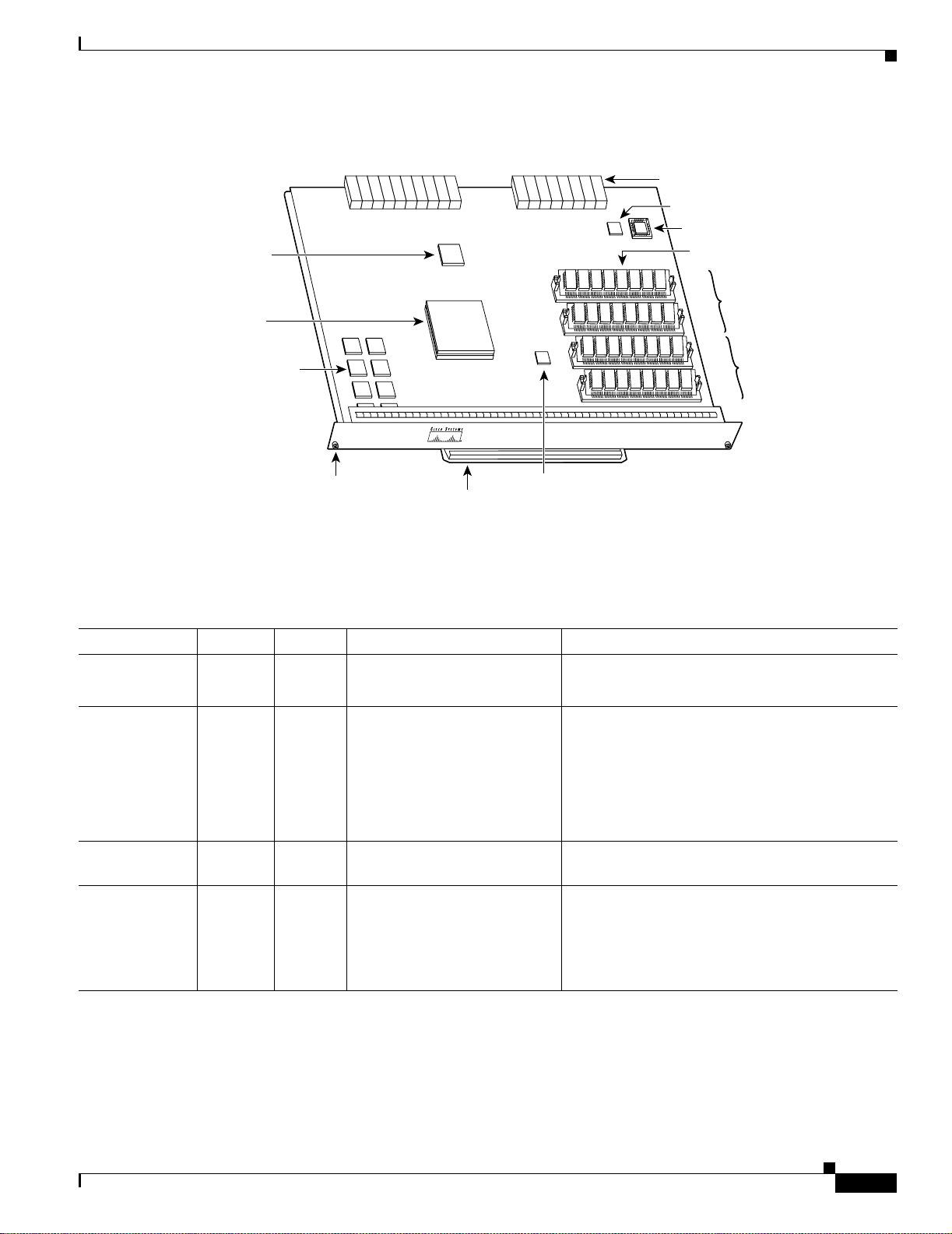
The NPE-100, N PE -150, a nd N PE- 200 c onsist of t he fo l lowing com pon en ts:
• Reduced instructio n set compu tin g ( RISC ) m icr oproc ess or
• System controller that uses direct memory access (DMA) to transfer data between DRAM and
Physical Description
–
The NPE-100 and the NPE-150 have an R4700 microprocessor that operates at an internal clock
speed of 150 megahertz (MHz).
–
The NPE-200 has an R5000 mic ropro cessor tha t operate s at an inte rnal cloc k speed of
200 MHz.
packet SRAM on the n etwork pro cessi ng e ngine .
• DRAM for storing rout ing tab les, prot ocols, ne twork a cco unti ng a ppli cations, p ackets of
information in prepara tion for proc ess switch ing, and packe t buffering for SRAM overflow. The
standard configuration is 32 megabytes (MB), with up to 128 MB available through single in-line
memory module ( SIM M) u pgrad es.
• Packet SRAM for storing packets of informat ion in prepa ration for fast switching.
–
The NPE-100 does not have SRAM.
–
The NPE-150 has 1 MB of SRA M.
–
The NPE-200 has 4 MB of SRA M.
• Unified cache SRAM that functions as the secondary cache for the microprocessor. (The primary
cache is within the microprocessor.)
• Two environmental sensors for m onitor ing t he c ooling a ir a s it l eaves the Cisc o 7204 chassis.
• Boot ROM for storing sufficient code for booting the Cisco IOS software. (This comp onent is only
available on the NPE-200.)
The network proc ess ing e ng ines pe rfor m t he fol lowing sys te m ma na geme nt fun ction s :
• Sending and receiving routing pr otocol upda tes
• Managing tables, caches, and buffers
• Monitoring interface and environmental status
• Providing Simple Network Management Protocol (SNMP) management and the console/Telnet
interface
OL-5101-02
• Accounting and switc hing of data tra ffic
• Booting and reloading images
• Managing port ad ap ters (r ecog ni ti on an d i n itia liz atio n d uri ng OIR )
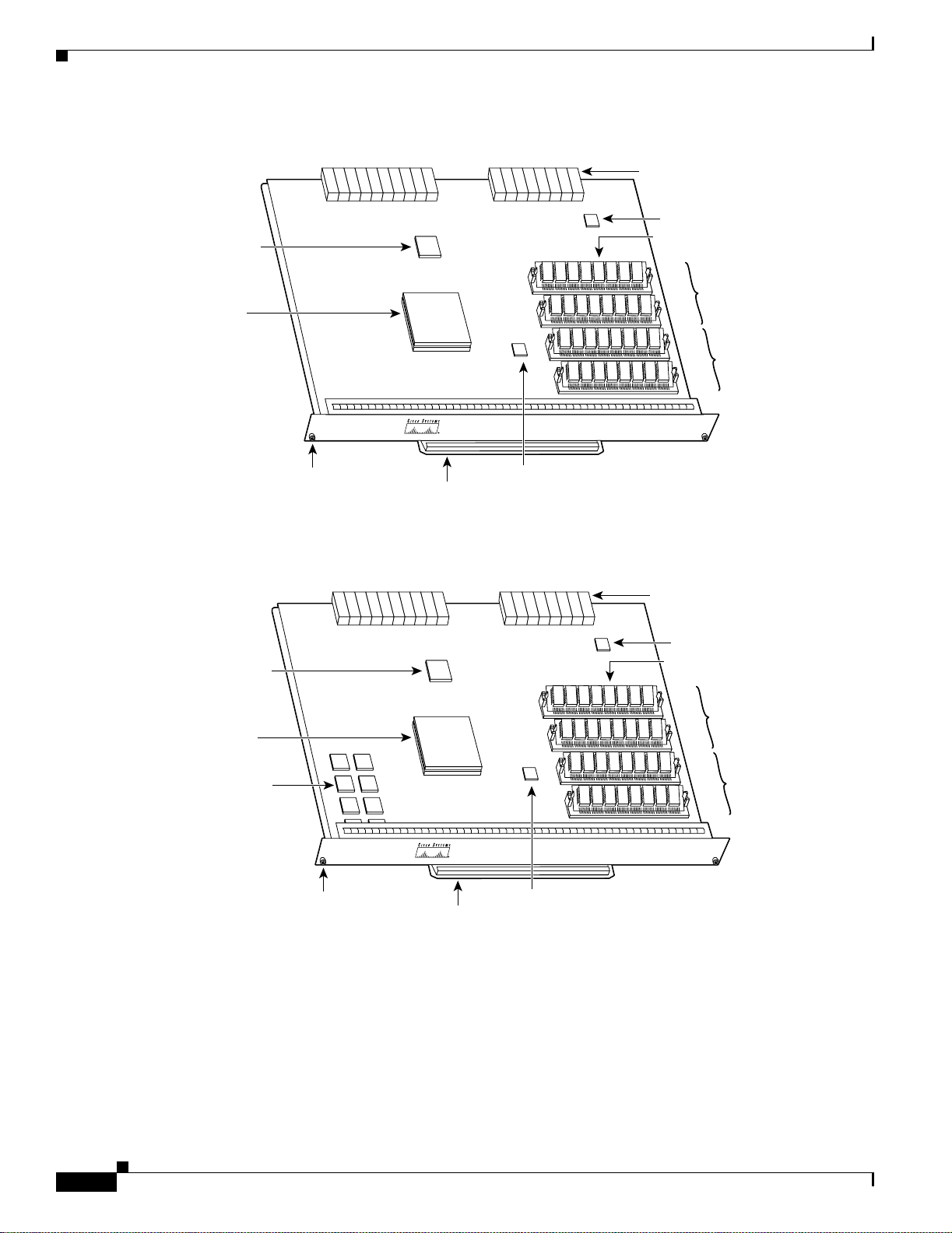
Figure 1-4 shows the NPE-100, Figu re 1-5 shows the NPE-150, and Figure 1-6 shows the NPE-200.
Cisco 7204 Installation and Configuration Guide
1-7
Page 24
Physical Descriptio n
Figure 1-4 Network Processing Engine—100
System
controller
R4700
microprocessor
Midplane
connectors
Temperature
sensor
DRAM SIMMs
U12
U4
U25
U18
N
ET
W
OR
K PR
O
C
ES
SIN
G
E
Chapter 1 Product Overview
Bank 1
Bank 0
N
GIN
E-100
H8822
Captive
installation
Handle
Temperature
screw
Figure 1-5 Network Processing Engine—150
System
controller
R4700
microprocessor
1-MB SRAM
U700 through U703
U800 through U803
Captive
installation
screw
Handle
sensor
Temperature
sensor
Midplane
connectors
Temperature
sensor
DRAM SIMMs
U12
U4
U25
U18
N
E
T
W
O
R
K
P
R
O
C
ESS
IN
G
E
Bank 1
N
G
IN
E
-150
Bank 0
H5999
1-8
Cisco 7204 Installation and Configuration Guide
OL-5101-02
Page 25
Chapter 1 Product Overview
Figure 1-6 Network Processing Engine—200
System
controller
R5000
microprocessor
4-MB SRAM
U6, U10, U13,
U14, U28, U29,
U38, and U39
Midplane
connectors
Temperature
sensor
Boot ROM U92
DRAM SIMMs
U52
U42
U25
U11
N
ET
W
O
R
K PR
O
CE
SSIN
G
Physical Description
Bank 1
Bank 0
EN
G
IN
E-200
H10310
Captive
installation
Handle
Temperature
sensor
screw
Table 1-1 lists the network processing engine memory components.
Table 1-2 Network Processing Engine Memory Components (NPE-100, NPE-150, and NPE-200)
Memory Typ e Size Quantity Description Location
DRAM 32 MB to
128 MB
3
SRAM
NPE-150
NPE-200
1 MB
4 MB
2 or 4 16- or 32-MB SIMMs (based
on maximum DRAM required)
8
8 chips, each being 128K words
x 9 bits wide
8
8 chips, each being 512K words
Bank 0: U18 and U25 or U11 and U25
Bank 1: U4 and U12 or U42 and U52
U700 through U 703
U800 through U 803
U6, U10, U13, U14, U28, U29, U38, and U39
x 8 bits wide
Boot ROM
(NPE-200 only)
Unified cache 512 KB 4 Secondary cache for the R4700
4
256 KB 1 PLCC-type integrated circuit
Socket U92
for the ROM monitor program
NPE-100 and NPE -150
and R5000 RISC processors
U2, U10, U14, and U26
1
2
NPE-200
U16, U9, U109, and U10 7
1. The sockets for bank 0 on the NPE-100 and the NPE-150 are numbered U18 and U25. The same sockets on the NPE-200 are numbered U11 and U25.
2. The sockets for bank 1 on the NPE-100 and the NPE-150 are numbered U4 and U12. The same sockets on the NPE-200 are numbered U42 and U52.
3. The NPE-100 does not have SRAM.
4. ROM = read-only memory.
Cisco 7204 Installation and Configuration Guide
OL-5101-02
1-9
Page 26

Physical Descriptio n
Note To prevent DRAM errors and to ensure your system initializes correctly at startup, DRAM bank 0
Chapter 1 Product Overview
(socket U18 and U25, or U11 an d U25) must contain no fewer than t wo SIMMs of the same type . You
may also install two SIMMs of the same type in bank 1 (socket U4 and U12, or U42 and U52); however,
bank 0 must always contain the two largest SIMM s.
Table 1-3 lists the network processing engine factory-installed DRAM configurations and their product
numbers.
Table 1-3 DRAM SIMM Configurations (NPE-100, NPE-150, and NPE-200)
Total DRAM DRAM Bank 0 Quantity DRAM Bank 1 Qu antity Product Number
32 MB U18 and U25
or
2 16-MB
SIMMs
U4 and U12 or
U42 and U52
– MEM-NPE-32MB
1
U11 and U25
64 MB U18 and U25
or
2 32-MB
SIMMS
U4 and U12 or
U42 and U52
– MEM-NPE-64MB
1
U11 and U25
128 MB U18 and U25
or
2 32-MB
SIMMs
U4 and U12 or
U42 and U52
2 32-MB
SIMMs
MEM-NPE-128MB
1
U11 and U25
1. These products are also available as DRAM upgrades. For example, to upgrade a network processing engine from 32 MB to
64 MB of DRAM, order produ ct nu mber MEM-NPE- 32MB=. A 16 MB-op tion (p roduct number ME M-NPE-16 MB=) , whi ch
consists of two 8-MB SIMMs, is also available from the factory as a DRAM upgrade.
Use the show version command to identify the network processing engine installed in your Cisco 7204
router. The following example shows an installed NPE-150:
Router> show version
Cisco Internetwork Operating System Software
IOS (tm) 7200 Software (C7200-J-M), Released Version 11.1(17)CA
Copyright (c) 1986-1996 by cisco Systems, Inc.
Compiled Sun 04-Aug-96 06:00 by rmontino
Image text-base: 0x60010890, data-base: 0x605F0000
(display text omitted)
cisco 7204 (NPE 150) processor with 12288K/4096K bytes of memory.
R4700 processor, Implementation 33, Revision 1.0 (Level 2 Cache)
Last reset from power-on
Bridging software.
(display text omitted)
1-10
Cisco 7204 Installation and Configuration Guide
OL-5101-02
Page 27

Chapter 1 Product Overview
Input/Output Controller
The Input/Output co ntrolle r shares the syst em memor y functi ons and the environmental monito ring
functions for the Cisc o 7204 router with the n etwork pro cessing e ngine.
Note Detailed instructions for removing and replacing the I/O controller are contained in the co nfiguration
note Input/Output Co nt roller Replacem ent I nst ructi ons. The configuration note is also available on
Cisco.com.
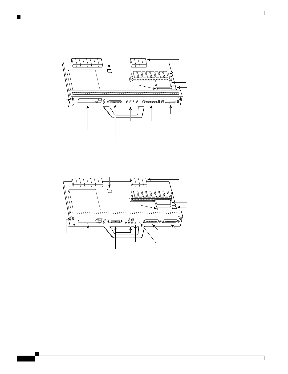
The I/O controller consists of the following components:
• Dual EIA/TIA-232 channels for local console and auxiliary ports. The console port has full DCE
functionality and a DB-25 port. The auxiliary port has full DTE functionality and a DB-25 plug.
• An optional Fast E th erne t po rt , eq ui pp ed w ith e ith er a singl e M II po rt ( see Figure 1-7) or an MII
port and an RJ-45 po rt ( se e Figur e 1-8 ), tha t i s co nfigurable f or use a t 1 00 megab its pe r sec on d
(Mbps) full-duplex or half-duplex (half-duplex is the default). The I/O controller without the Fast
Ethernet port is shown in Figure 1-9.
Physical Description
Note When you use the I/O contr oller that is equipped with an MII port and an RJ-45 port , only one port can
be configured for use at a time. Although still supported by Cisco Systems, the I/O c ontroller equipped
with the single MII por t was d iscon t inue d as an or dera ble pr odu ct in M ay 1 998 .
• NVRAM for storing the system configurat ion and environmental mo nitoring logs. NVR AM uses
lithium batteries to maintain its contents when disconnected from power.
• Flash memory SIMM for stor ing th e bo ot help er ima ge.
• Two PCMCIA slots for Flash Disks or Flash memory cards, w hich contai n the default Ci sco IOS
software imag e.
• Boot ROM for storing sufficient code for booting the Cisco IOS software.
• Two environmental sensors for m on itor ing the cool ing a ir a s it en t ers a nd leaves the Cisc o 7 204
chassis.
OL-5101-02
Cisco 7204 Installation and Configuration Guide
1-11
Page 28
Physical Descriptio n
Chapter 1 Product Overview
Figure 1-7 I/O Controller—with Fast Ethernet Port (Single MII Port)
Temperature
sensor
Midplane
connectors
Flash SIMM [U99]
D
E
L
B
A
N
E
Captive
installation
screw
PC Card slots
Boot ROM [U20]
1
T
I
I
O
L
M
S
E
F
T
A
I
C
M
C
P
0
T
C
E
O
J
L
E
S
T
E
K
K
E
L
O
N
S
I
B
I
5
E
I
R
A
L
4
R
M
J
N
E
W
K
R
N
F
E
P
U
N
E
I
P
E
L
IO
F
C
ER
TH
E
ST
A
F
X
U
A
R
T
N
CO
T
PU
T
U
/O
T
U
P
IN
T
E
N
E
L
O
S
N
O
C
Console
LEDs and
CPU reset
Auxiliary
port
port
button
ER
L
L
O
NVRAM [U41]
Temperature
sensor
H6000
Optional Fast Ethernet
port (MII receptacle)
Figure 1-8 I/O Controller—with Fast Ethernet Port (MII and RJ-45 Ports)
Temperature
sensor
Midplane
connectors
Flash SIMM [U99]
R
E
L
L
O
R
port
NVRAM [U41]
Temperature
sensor
H11293
Captive
Boot ROM [U20]
1
I
T
I
O
M
L
E
S
D
E
L
B
A
N
E
P
T
A
C
I
E
C
M
C
O
J
L
E
S
F
5
4
II
0
T
J
R
M
R
N
N
E
E
S
5
4
E
-
R
J
R
U
P
C
5
R
4
J
W
K
P
IN
K
L
IO
O
E
H
T
E
T
S
A
F
T
E
X
U
A
Auxiliary
N
R
P
IN
T
E
T
U
P
T
U
/O
T
U
L
O
S
N
O
C
Console
T
N
O
C
E
port
installation
screw
PC Card slots
Optional Fast Ethernet port
LEDs CPU reset button
(MII receptacle and RJ-45 receptacle)
1-12
Cisco 7204 Installation and Configuration Guide
OL-5101-02
Page 29
Chapter 1 Product Overview
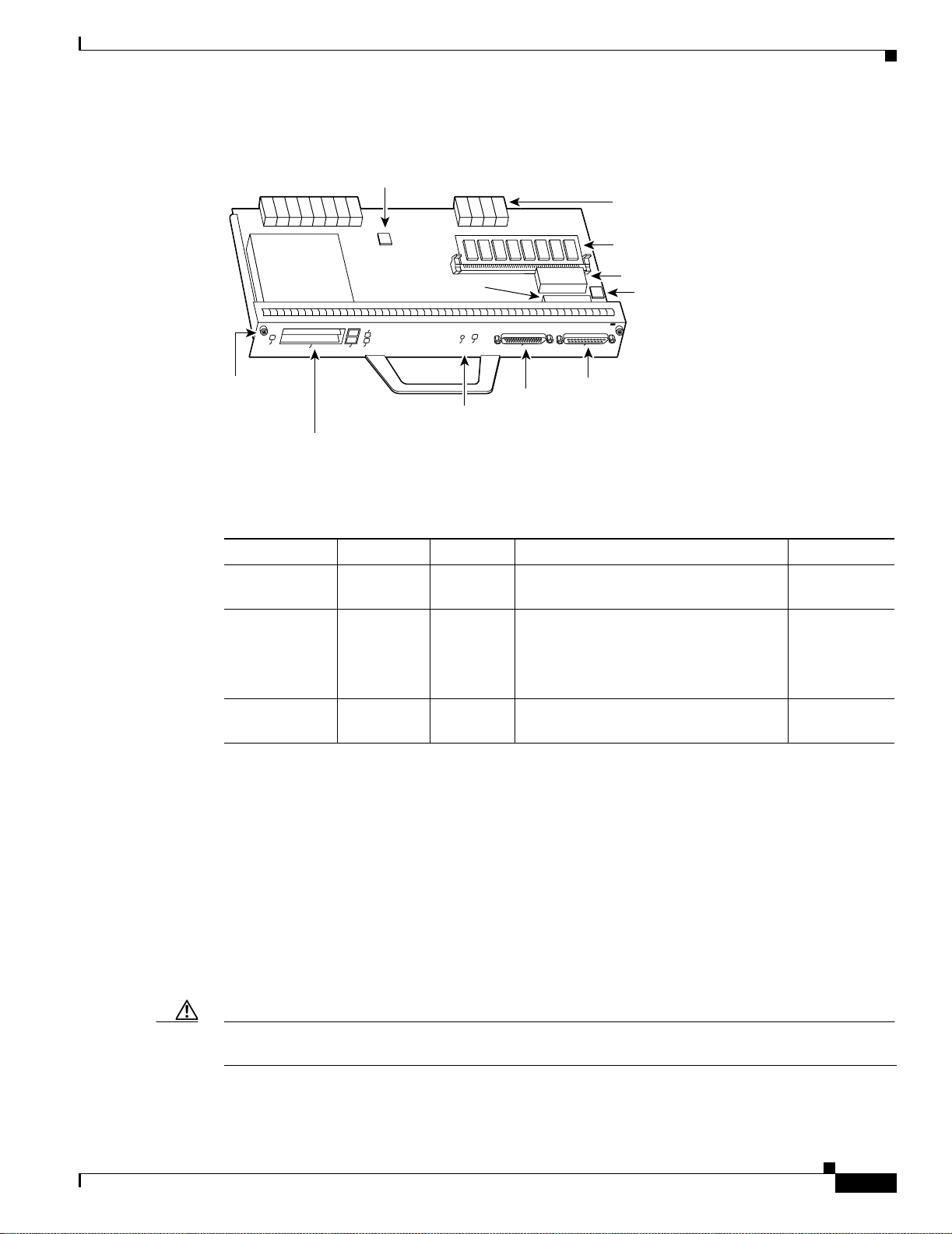
Figure 1-9 I/O Controller—without Fast Ethernet Port
Physical Description
Temperature
sensor
Midplane
connectors
Flash SIMM [U99]
NVRAM [U41]
D
E
L
B
A
N
E
Captive
installation
screw
PC Card slots
Boot ROM [U20]
1
T
O
L
S
T
0
T
C
IA
E
C
M
C
P
O
J
L
E
S
T
R
E
E
S
W
E
O
R
K
P
U
O
P
IO
C
X
U
A
N
T CO
PU
T
U
/O
T
U
P
IN
E
L
O
S
N
O
C
Console
port
LED and
Auxiliary
port
CPU reset
button
R
E
L
L
O
R
T
Temperature
sensor
H7400
Table 1-3 lists the I/O controller memory components.
Table 1-4 I/O Controller Memory Components
Memory Typ e Size Quantity Description Location
Boot ROM 256 KB 1 DIP-type integrated circuit for the ROM
U20
monitor program
Flash SIMM
Flash memory
card
4 MB
8 to 20 MB1Up to 2
Contains the default boot helpe r image
Contains the default Cisco IOS image
U99
PCMCIA
slot 0 and
slot 1
NVRAM 128 KB 1 Nonvolatile EPROM for the system
U41
configuration file
OL-5101-02
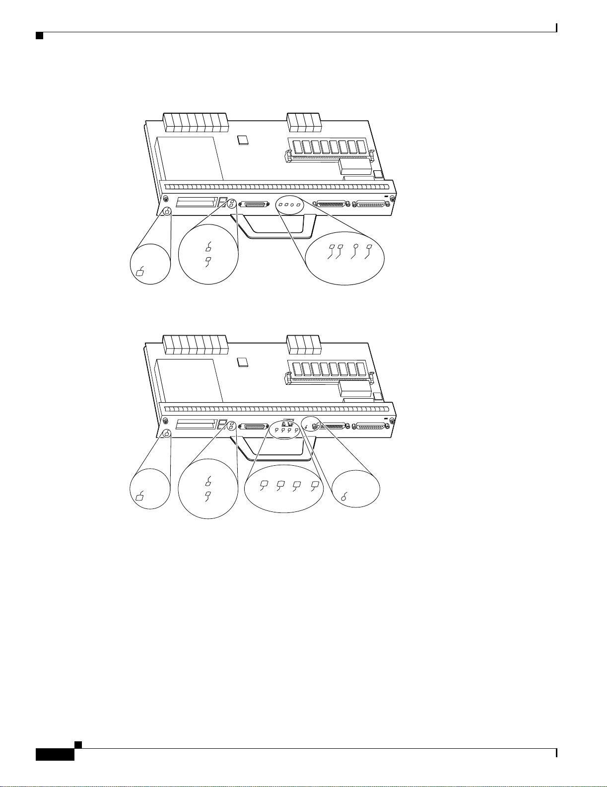
Depending on whether the Fast Ethernet port is present, up to five LEDs on the I/O controller faceplate
indicate system stat us; two ad diti onal LEDs in dic ate the sta tus of the Flas h mem ory c ards i nstal led in
either PCMCIA slot.
Figure 1-10 shows the LEDs on the I/O controller with the Fast Ethernet port that is equipped with a
single MII port. Figu re 1-11 shows the LEDs on the I/O controller with the Fast Ethernet port that is
equipped with an MII port and an RJ-45 port. Figure 1-12 shows the LEDs on the I/O co ntroll er without
the Fast Ethernet port. Table 1-5 l ists I/O control ler LE Ds and the ir functi ons. To use the LEDs for
troubleshooting the I/O controller, refer to the “Identifying Startup Problems” section on page 5-3 in
“Chapter 5, “Troubleshootin g th e Insta llat ion. ”.”
A CPU reset button is located next to the IO power OK LED or the auxiliary port on the I/O controller
faceplate. The CPU reset button resets the entire system.
Caution To prevent system errors an d p robl ems , use the CPU re set button only at the dir ecti on of yo ur se rvice
representative.
Cisco 7204 Installation and Configuration Guide
1-13
Page 30
Physical Descriptio n
Chapter 1 Product Overview
Figure 1-10 I/O Controller LEDs and CPU Reset Button—with Fast Ethernet
Port (Single MII Port)
D
E
L
B
A
N
E
FAST ETHERNET INPUT/OUTPUT CONTROLLER
H6523
SLOT 1
D
E
L
B
A
N
E
SLOT 0
FE
FE LINK
ENABLE
CPU RESET
IO POWER OK
Figure 1-11 I/O Controller LEDs and CPU Reset Bu tton—with Fast Ethernet Port (MII and RJ-45 Por ts)
FAST ETHERNET INPUT/OUTPUT CONTROLLER
T
E
S
5
4
E
-
R
J
R
U
D
E
L
B
A
N
E
D
E
L
B
A
N
E
SLOT 1
4
II
J
R
M
N
N
E
E
MII
RJ45
EN
EN
SLOT 0
P
C
5
5
R
4
J
W
K
R
P
IN
K
L
IO
RJ45
LINK
O
IO PWR
PU RESET
OK
C
H11294
1-14
Cisco 7204 Installation and Configuration Guide
OL-5101-02
Page 31

Chapter 1 Product Overview
Figure 1-12 I/O Controller LEDs and CPU Reset Button—without Fast Ethernet Port
Physical Description
1
T
O
L
D
E
L
B
A
N
E
IA
C
M
C
P
D
E
L
B
A
N
E
SLOT 0
E
J
E
SLOT 1
S
T
0
T
C
O
L
S
IO POWER
OK
R
E
S
W
E
O
R
P
K
U
O
O
P
I
C
CPU RESET
T
E
IN
X
U
A
R
E
L
L
O
TR
N
O
C
T
PU
T
U
/O
T
U
P
E
L
O
S
N
O
C
H7401
I
Table 1-5 I/O Controller LEDs
LED Function
IO Power OK Indicates that the I/O controller is on and receiving DC power from the router
midplane. T his LED c omes on during a s uccessfu l route r boot an d remain s on
during normal opera tion of the ro uter.
Enabled Indicates that the network processing engine and the I/O controller are
enabled for operation by the system; however, it does not mean that the Fast
Ethernet port on the I/O controller is func tiona l or en ab led. Th is LE D come s
on during a successful router boot and remains on during normal operation of
the router.
FE Enable Indicates that the Fast Ethernet port on the I/O controller is initialized and
enabled for operation by the system. This LED comes on after the I/O
controller has been enab led and rema ins on duri ng normal o peration of the
router.
FE Link Indicates that the Fast Ethernet port on the I/O controller has established a
valid link with the netw ork. This LED remains of f during normal operat ion of
the router, unless there is an incoming carrier signal.
MII EN Indicates that the Fast Ethernet port’s MII ports is initialized and enabled by
the system, and configured for operation. This LED comes on after the I/O
controller has been enabled and the MII port has been configured as the media
type for the Fast E the rnet p ort (the RJ- 45 po rt is t he de fault me dia type for
the Fast Eth er n et po rt). This LED re mains on during normal operat io n of the
router.
RJ45 EN Indicates that the Fast Etherne t port’s RJ-45 port ( the de fault m ed ia typ e for
the Fast Ethernet port) is initialized and enabled by the system. This LED
comes on after the I/O contro ller has been en abled and remains on dur ing
normal operation of t he rout er.
OL-5101-02
Cisco 7204 Installation and Configuration Guide
1-15
Page 32

Physical Descriptio n
Note The I/O controller without the Fast Ethernet port does not have the FE enabled LED and the FE link LED.
Note An MI I L INK L ED is n ot pr ovide d on t he I/O co nt ro ller be ca use t h e LE D is provid ed on exter na l
Chapter 1 Product Overview
Table 1-5 I/O Controller LEDs (continued)
LED Function
RJ45 LINK Indicates that th e Fast Ethernet port ’s RJ-45 port has established a valid link
with the network. Th is L E D re mai ns off du ring n orm al opera ti on of t he
router, unless there is an incoming carrier signal.
Slot 0 Slot 1 Goes on to indicate which PCMCIA slot is in use when either slot is being
accessed by the syst em . Th ese L EDs re mai n off during no rmal opera tio n of
the router.
The I/O controller without the Fast Ethernet port and the I/O controller that is equipped with a single
MII port do not have the MII enabled, RJ-45 ena bled, and RJ- 45 link LE Ds.
transceivers that are required for connecting to the MII port on the I/O controller. Refer to the section
“Fast Ethernet Connection Equipment” section on page 3-16 inChapter 3, “Installing the Cisco 7204”
for Fast Ethernet M II conn ec tion re quir emen ts.
Use the show di ag 0 command to identify the I/O controller (with or without the Fast Ethernet port)
installed in your Cisco 7204 router.
Note Slot 0 in Cisco 7200 series routers is always reserved for the Fast Ethernet port on the I/O controller—if
present. If the I/O controller without the Fast Ethernet port is installed in your Cisco 7200 series router,
the system software will not display output for the show diag 0 command.
Note Refer to t he s ec tion ““Port Adapter Slot and Logical Interface Numbering” section on page 1-23 for
information about port adapter slot numbering and logical interface numbering for the Cisco 7204 router.
The following sample output fr om the show diag 0 comma nd is from a Ci sco 7204 I/O control ler with
the Fast Ethernet por t th at is eq uippe d with a n MI I p ort an d RJ-4 5 p ort:
Router> show diag 0
Slot 0:
Fast-ethernet on C7200 I/O with MII or RJ45 port adapter, 1 port
Port adapter is analyzed
Port adapter insertion time 00:10:42 ago
Hardware revision 2.0 Board revision A0
Serial number 3511336 Part number 73-1537-03
Test history 0x0 RMA number 00-00-00
EEPROM format version 1
EEPROM contents (hex):
0x20: 01 14 02 00 00 35 94 28 49 06 01 03 00 00 00 00
0x30: 50 0000 00 FF FF FF FF FF FF FF FF FF FF FF FF
1-16
Cisco 7204 Installation and Configuration Guide
OL-5101-02
Page 33

Chapter 1 Product Overview
The RJ-45 port is the default medi a ty pe for t he I/O c ontro l ler tha t is eq uippe d w ith an M II po rt and an
RJ-45 port. Use th e media-ty pe comm and to cha nge the
I/O controller ’s media type a nd t he show in terfac es comm and to verify the ch ange . The following
example configures the MII port as the media type fo r the I/O con troll er:
Router# config t
Enter configuration commands, one per line. End with CNTL/Z.
Router(config)# int fastethernet 0/0
Router(config-if)# media-type mii
Router(config-if)# no shutdown
Router(config-if)# exit
Router(config)#
%LINEPROTO-5-UPDOWN: Line protocol on Interface FastEthernet0/0, changed
state to up
%LINK-3-UPDOWN: Interface FastEthernet0/0, changed state to up
Router# sh int fastethernet 0/0
FastEthernet0/0 is administratively up, line protocol is up
Encapsulation ARPA, loopback not set, keepalive not set, hdx, MII
Physical Description
(display text omitted)
(display text omitted)
Use the media-type 100X command to return the media type to the RJ-45 port.
The default transmission mode for the Fast Ethernet port on the I/O controller is half-duplex. Use the
full-duplex command to change the Fast Ethernet port’s transmission mode and the show interf aces
command to verify the change as follows:
Router# config t
Enter configuration commands, one per line. End with CNTL/Z.
Router(config)# int fastethernet 0/0
Router(config-if)# full-duplex
Router(config-if)# no shutdown
Router(config-if)# exit
Router(config)#
%LINEPROTO-5-UPDOWN: Line protocol on Interface FastEthernet0/0, changed
state to up
%LINK-3-UPDOWN: Interface FastEthernet0/0, changed state to up
Router# sh int fastethernet 0/0
FastEthernet0/0 is administratively up, line protocol is up
(display text omitted)
Encapsulation ARPA, loopback not set, keepalive not set, fdx, 100BaseTX
(display text omitted)
Use the no full-duplex command to return the Fast Et her net po rt o n the I/O c on trol ler to hal f- duplex
transmission mode.
Port Adapters and Service Adapters
The Cisco 7204 is shipped from the factory with up to four installed port adapters and service adapters.
Port adapters provide a variety of net work me dia type s (b ased on yo ur or de r) for t he rout er a nd ser vic e
adapters provide hardware-based services (such as data compression and encryption) for the port adapter
media types. The port and service adapters connect directly to the router’s midplane. Port and service
adapters instal led in th e Ci sco 7204 router suppo rt O I R.
OL-5101-02
Cisco 7204 Installation and Configuration Guide
1-17
Page 34

Physical Descriptio n
Caution To ensure adequate airflow across the router’s port adapters, a port adapter or a blank port adapter must
Note Detai led instru ctions for removing, re placi ng, and co nfigurin g the port and ser vice ad apter types
Power Supplies
Chapter 1 Product Overview
For a description of OIR, refer to “Online Insertion and Removal” section on page 1-25. For general
instructions about how to replace a port or service ad apter , refer to the section “Replacing a Port Adapter
or Service Adapter” section on page 6-3 in “Chapter 6, “Maintaining the Cisco 7204.”
be installed in each port adapter slot.
supported by the Cisco 7206 are containe d in the configura tion note for each port and service a dapter.
For example, if you p lan t o re plac e a PA-A3 enhanced ATM port adapter in your Cisc o 7206 router,
PA-A3 Enha nc ed ATM Port Adapter Installation and Co nfiguration. This document is available on
Cisco.com.
The Cisco 7204 comes equipped w ith one 280W AC-input power supply or one 280W DC-input power
supply. You must order the se cond power sup ply sep arate ly.
Caution Do not mix power supplies in the Cisco 7204. In dual power supply configurations, both power supplies
must be of the same type (two AC-input p ower suppl ies or two DC -inp ut p ower suppli es).
Note Detaile d instru ctions for handling a nd replaci ng the Cisco 7204 power supplies are containe d in the
configuration notes 280-W att AC-Input Power Supply Replacement Instructions and 280-Watt DC-Input
Power Supply Replacement Instructi ons. This doc ument is available on Cisco.co m.
A handle on the AC and DC power supplies provides a grip point for removing and replacing the power
supply. (Figure 1-13 shows the faceplate of the AC-input power supply. Figure 1-14 shows the f acep late
of the DC-input power supp ly.) Two captive installation screws secur e t he power suppl y to the cha ssis
and seat the power supply in the rout er midpla ne. A power OK LED indicat es that the power supply is
delivering +5 VDC to t he ro ut er m i dpla ne.
The AC-input power supply has a receptacle for an AC-input power cable. A modular power cable
connects the AC-input power supply to the site AC power source. A cable- retention clip secures the
power cable to the AC-input p ower supply.
The DC-input power supply has DC-input power leads that are hardwired to a DC-input terminal block.
A cable tie is shipped with each DC-input power supply to secure the leads to the power supply faceplate
and provide strain relief for the leads.
1-18
Cisco 7204 Installation and Configuration Guide
OL-5101-02
Page 35

Chapter 1 Product Overview
Figure 1-13 AC-Input P ower Supply
Captive
installation
Figure 1-14 DC-Input Power Supply
screw
OK LED
Power
switch
Power
switch
Physical Description
H6432
AC-input
receptacle
Handle
H8618
DC-input
receptacle
Handle
Captive
installation
screw
Power
switch
guard
OK LED
Power
switch
Caution To ensure adequate airflow across the router’s power supplies, a power supply or a power supply filler
plate must be installed in each power supply bay. Figure 1-13 shows a Cisco 7204 with an installed
power supply filler plate.
Table 1-1 li sts the AC-input an d D C-i npu t power supp ly syst em power spec ification s, inc ludi ng inpu t
voltage and operating f reque ncy range s.
Note Each AC-input power supply operati ng at 120 VAC requires a minimum of 5A service. We recommend
powering the Cisco 7204 fro m a 15A re ceptac le at the power sour ce.
Note Each DC-input power supply operatin g at –48 VDC in North America requires a minimum of 13A
service. Each D C-in put p ower supply op er ati ng at –60 VDC in the European Community requires a
minimum of 8A service.
OL-5101-02
Cisco 7204 Installation and Configuration Guide
1-19
Page 36

Physical Descriptio n
Fan Tray
Chapter 1 Product Overview
This product relies on the bu ildin g’s installation for short-circuit (overcurre nt ) prote ction . En sure th at a
listed and ce rti fied fu se or cir cui t br ea ker, 20A min imum 60 V DC , i s u sed o n a ll cu rre nt -car ry ing
conductors.
The power OK LED goes off and the power supply will shut itself down when the internal DC voltages
exceed allowable tolerances or the internal temperature of the power supply exceeds allowable
tolerances. The power supply will remain in a shut down state until it is disconnected and reconnected
to the source po wer, and then restarted with the power switch. The power switch turns the power supply
on and starts the system. For a description of power-supply shutdown conditions and thresholds, refer to
the ““Environmental Monitori ng and Repor ting Function s” se ction on p age 1-26”.
The fan tray, shown in Figure 1-15, consists of three fans that are enclosed in a metal case. The fan tray
is located in the subchass is and re ceives –12 VDC through a DC power harness that connects directly to
the router midplane. You must remove the subchassis to access the fan tray.
Figure 1-15 Cisco 7204 Fan Tray
DC power
harness
Alignment
tabs
H6430
The fan tray draws cooling air in through the intake vent on the right sid e of the chassi s (whe n viewing
the router from the front), and moves the air across the internal components and out the exhaust vent on
the left side of the chassis.
Figure 1-16 shows the air flow through the router.
1-20
Cisco 7204 Installation and Configuration Guide
OL-5101-02
Page 37

Chapter 1 Product Overview
Figure 1-16 Internal Air Flow—Top View
Physical Description
Power supply end
Chassis
Exhaust
air
Inlet
airflow
H6237
Port adapter end
The left and right sides of the chassis must remain unobstructed to ensure adequate air flow and prevent
overheating inside the chassis; we recommend at least three inches of clearance. (See the “Site
Requirements” secti on on page 2-4 in the chapter Chapter 2, “Preparing for Installation.”)
Temperature sensors on the network proc essi ng en gi ne a nd I/O con trol le r mon ito r th e int erna l a ir
temperature and send warning messages when the internal air temperature approaches a specified
threshold. If the inte rnal te mperatur e e xceed s the spec if ied threshold, the sy stem en v ironmental monitor
shuts down all internal power to prevent equipment damage from excessive heat.
The Cisco 7204 chassis, shown in Figure 1-17, has four slots for the port adapters , one slot for t he I/O
controller, and one bay for the subchassis. To replace the chassis, you must remove all of the internal
components, incl uding the subc hassi s.
OL-5101-02
Note Because you must rem ove all the internal components w hen repl acing the chassis, re fer to the
configuration notes tha t expl ain how to re move and repl ace the i nte rn al c om ponen t s. T he se doc um en ts
are available on Cisco.com.
Cisco 7204 Installation and Configuration Guide
1-21
Page 38

Physical Descriptio n
Chapter 1 Product Overview
Figure 1-17 Cisco 7204 Chassis
3
5
PCMCIA Flash Disks and Flash Memory Cards
The Cisco 7204 suppor ts up t o two in stall ed PCM CIA Fla sh Di sks or two Flash me mory c ards.
Note To avoid potential problems when inser ting sp ar e Fl ash Disks or Flas h m emor y c ards in you r
Cisco 7204, we re comme nd tha t y ou refor mat al l of y our Fl ash D isks or Fla sh m emor y card s on a
Cisco 7 204 running one of the recommended Cisco IOS software releases. The chapter Chapter 6,
“Maintaining the Cisco 7204” contains instructions that explain how to reformat a Flash memory card.
Flash memory (Flash Disks or cards and the Flash SIMM on the I/O controller) allows you to remotely
load and store mul tiple sys tem and b oot helpe r images. You can do wnload a ne w image o v er the netwo rk
and then add the new image to Flash me mory or re place existi ng files. You can also transfer images
between Flash Disks or cards and the onboard Flash memory SIMM. You can then boot the router either
manually or automat ically fro m any of the store d images. Flash memo ry can also function as a TFTP
server to allow other routers to boot remote ly from stor ed imag es or copy them i nto their own Flash
memory.
Cisco 7200
SERIES
4
2
0
H7402
1-22
Note For procedures that explain the use of the PCMCIA Flash Disk, refer to the Using the Flash Disk
document .
For proced ures that e xpl ain h o w t o re place ma in, Flas h, and ROM monitor memory in Cisco 7200 series
routers, refer to the Memory Replac ement Instru ction s for the Network Processing Engine and
Input/Output Controller docum ent .
The preceding docum ents are available on Cisco.com. Ins truct ions for instal ling and removing a Flash
memory card are also contained in the “Installing and Removing a Fla sh Me mo ry Card” section on
page 6-7 in Chapter 6, “Maintaining the Cisco 7204” of th is guide.
Cisco 7204 Installation and Configuration Guide
OL-5101-02
Page 39

Chapter 1 Product Overview
Table 1-6 list s the Flash memory c ard options supp orted by the Cisco 7204.
Table 1-6 Flash Memory Card Options
Memory Size Product Number
16 MB MEM-I/O-FLC1 6M
20 MB MEM-I/O-FLC2 0M
1. These products are also availa ble as Flash car d upgrades . To order an upgrade, ad d an equal sign (=) a fter the product number,
Table 1-7 lists the Flash Disk options supp orted by the Cisco 7204.
Table 1-7 Flash Disk Options
Memory Size Product Number
40 MB MEM-I /O- FLD4 0M
110 MB MEM-I/O-FLD110M
1. These products are also available as Flas h Disk up grades. To order an u pgrade, add an equa l sign (= ) after the product n umber,
Functional Overview
1
1
for example, MEM-I/O-FLC16M=.
1
1
for example, MEM-I/O-FLD110M=.
Rack-Mount and Cable-Management Kit
The rack-mount and ca ble-m anagem ent kit for t he Cisco 7204 consists of rack-mo unt and
cable-managemen t br ac kets th at ar e de signe d for m oun t ing y our rout er i n 1 9-inc h, 4 -po st or 2 -po st
equipment racks and for relieving strain on port adapter interface cables that are installed on port
adapters in the router. The kit is shipped with each Cisco 7204 and is also available as a single FRU.
For detailed instructio ns about how to install the rack-mount and cable-management brackets on your
Cisco 7204, refer to the “Rack-Mounting the Cisco 7204” section on pa ge 3-1” and the “General
Installation” section on page 3-9” in Chapter 3, “Installing the Cisco 720 4.”
Functional Overview
This section provides a functi onal overview of the Cisco 7204. It describes the numberi ng and
addressing of the port adapters for the router, the environmental monitoring and reporting functions, and
online insertion and removal (OIR). These de scripti ons will he lp you beco me familia r with the
capabilities of the Cisco 7204 router.
Port Adapter Slot and Logica l Inter fac e Numb ering
In the Cisco 720 4, the p ort ad apte r sl ot n um ber i s the cha ssis sl ot in w hic h a por t or se rv ice a dapt er is
installed, whil e t he log ica l i nte rfac e nu mbe r is t h e physi cal loca ti on of t he int erfa ce p ort on a po rt
adapter (service adapters do not have interface ports). Port adapter slots are numbered from 1 through 4;
port adapter slot 0 is reserved for the optional Fast Ether net port on the I/O controller—if prese nt. (Refer
to Figure 1-2 for the num bering scheme of the port adapter s lots.) The nu mber of logical int erfaces
depends on the typ e of po rt a da pte r.
OL-5101-02
Cisco 7204 Installation and Configuration Guide
1-23
Page 40

Functional Overview
Chapter 1 Product Overview
The Media Acce ss Control (MAC) or hardware address is a standardized data link layer address that is
required for certain net work inter face types. Th ese ad dresses are n ot used by other devices in the
network; they are specific and unique to each port. The Cisco 7204 uses a specific method to assign and
control the MAC addresses of its port adapters. For a description of the MAC-layer address, see the
section “MAC Address ” section on page 1-25 in this chapter.
Port adapter slots maintain the same slot number regardless of whether other port or service adapters are
installed or removed. However, when you move a port adapter to a different slot, the port adapter’s slot
number changes to refle ct the new slot numbe r.
You can identify port adapter slots by using software commands to display information about a specific
port or service adapter or for all port and service adapters in the Cisco 7204. To display information
about all port adapte r slot s, use th e sh ow in terf ac es command. To display information about a specific
port adapter slot, use the show interfaces command with the port adapte r type and slot num ber in the
format show interfaces (port adapter type and slo t nu mber/port number). If you abbreviate the
command (sh int) and do not specify port adapter type and slot number (or arguments), the system
interprets the command as show interfaces and displays the status of all port adapters and ports.
Following is an example of how the show interfaces command, used without arguments, displays status
information (inc lu din g th e physi cal por t ada pter n umb er ) for e ach po rt a da pte r in a C is co 7204.
In the following example, most of the status information for each interface is omitted.
Router# sh int
FastEthernet0/0 is administratively up, line protocol is up
Hardware is DEC21140, address is 0000.0000.0000 (bia 0000.0000.0000)
Internet address is 1.1.1.3
MTU 1500 bytes, BW 100000 Kbit, DLY 100 usec, rely 255/255, load 1/255
(display text omitted)
Fddi1/0 is administratively down, line protocol is down
Hardware is MIF68840_MM, address is 0000.0000.0000 (bia 0000.0000.0000)
Internet address is 1.1.1.0
MTU 4470 bytes, BW 100000 Kbit, DLY 100 usec, rely 255/255, load 1/255
(display text omitted)
Ethernet2/0 is administratively up, line protocol is up
Hardware is AmdP2, address is 0000.0000.0000 (bia 0000.0000.0000)
Internet address is 1.1.1.7
MTU 1500 bytes, BW 100000 Kbit, DLY 1000 usec, rely 255/255, load 1/255
(display text omitted)
You can also use arguments such as the interface type (Ethernet, TokenRing, Fddi, and so forth) and the
port address (slo t/p ort) to displ ay i nfor ma tion ab out a specific i nter face onl y.
The following example shows the display for the first port on the T oken Ring port adapter in port adapter
slot 3:
Router# sh int tokenring 3/0
TokenRing3/0 is administratively down, line protocol is down
Hardware is IBM2692, address is 0000.0000.0000 (bia 0000.0000.0000)
Internet address is 1.1.1.8
MTU 4464 bytes, BW 1600 Kbit, DLY 630 usec, rely 255/255, load 1/255
Encapsulation SNAP, loopback not set, keepalive set (10 sec)
ARP type: SNAP, ARP Timeout 04:00:00
Ring speed: 16 Mbps
(display text omitted)
1-24
For complete descriptions a nd instruct ions for th e comm ands used to configure your Ci sco 7 204, re fer
to the Configuration Fundamentals Co nfiguration Gu ide and Configuration Fu ndament als Comman d
Reference publications, w hic h are available o n C is co.c om.
Cisco 7204 Installation and Configuration Guide
OL-5101-02
Page 41

Chapter 1 Product Overview
MAC Address
Functional Overview
LAN interfac es (ports) require un ique MA C a ddresses, also kno wn as hardware addresses. T ypically , the
MAC address of an interface is stored on a memo ry compone nt that re sides dir ectly on th e interfac e
circuitry; however, the OIR feature requires a different met hod. For a descr iption of O IR, refer to the
section ““O nline Insert ion and Removal” se ction on p age 1-25”.
The OIR feature allows you to remove a port or service adapter and replace it with another identically
configured one. If the new port or ser vice ad apter ma tches the adapt er you removed, th e system
immediately brings it on line. In order to allow OIR, an address allocator with a unique MAC addresses
is stored in an EEPROM on the router midplane. Each address is reserved for a specific port and slot in
the router regardless of whether a port or service adapter resides in that slot. The MAC addresses are
assigned to the slots in sequence. The first address is assigned to slot 0, and the last address is assigned
to slot 6. This address scheme allows you to remove port and service adapters and insert them into other
routers without causin g the MAC addresses to move around the ne twork or be assig ned to mul tiple
devices.
Note that if the MAC addresses were stored on eac h port or servi ce ada pter, OIR would not function
because you could never replace one adapter with an identical one; the MAC addresses would always be
different. Also, each t ime a por t or serv ice ada pte r was re place d, othe r devices on the net work wo uld
have to update their data structures with the new address, and, if they did not do so quickly enough, could
cause the same MAC address to appear in more than one device at the same time.
Note Storing the MAC addresses for every slot in one central location means the addresses stay with the
memory device on which they are stored.
Online Insertion and Removal
All port and service adapters in the Cisco 7204 support online insertion and remo val (OIR).This functio n
allows you to install and r eplace por t and service adapter s while the rou ter is operati ng; you do not nee d
to notify the software or shut down the system power. This provides a method that is seamless to end
users on the network, mai ntain s al l ro uting info rm ati on, a nd e nsu res se ssion prese rvation.
The following is a functional des cript ion of OIR for bac kgroun d informa tion only; for specific
procedures for installing and replacing a port or service adapter in a Cisco 7204 router, refer to the
configuration note that was shipped with the port or service adapter hardware.
Caution The network processin g engine a nd the I/O con trolle r are requi red system compone nts that cannot be
removed if the router is operat ing. Removing the network processing engine or the I/O c ontroller while
the router is operating w ill c ause the router t o shut d o wn o r crash , and might dam age or d estroy m emory
files.
Each port and service adapter has a bus connector that connects it to the router’s midplane. Each
midplane connector has a set of tiered pins in three lengths that send specific sig nals to the system as
they make contact with the port adapter. The system assesses the signals it receives and the order in
which it receives them to determine if a port or service adapter is being removed or inserted into the
midplane. From these signals, the system det ermines whether to reinitia lize a new in terface or shut do wn
a remove d int erfac e. Fo r ex ample, when ins erting an port a dapter , the lon gest pins make contact wit h the
port adapter first, and the sh orte st pin s m ake conta ct last. Th e syste m re cogni ze s the sig na ls a nd th e
sequence in wh ich it re c eives them.
OL-5101-02
Cisco 7204 Installation and Configuration Guide
1-25
Page 42

Functional Overview
When you remove or inse rt a port o r s ervi ce ad apt er in a Cisco 7204 router, the midpla ne p ins s end
signals to notify the system, which then performs as follows:
1. Rapidly sca ns the midpla ne for configur ation cha nges.
2. Initializes all newly inserted port and service adapters, noting any removed port adapter interfaces
and placing them in the adm inistra tively shut down state.
3. Brings all previously configured interfaces on the port adapter back to the state they were in when
they were removed (ser vice adapters do not have interfaces). Any newly inserted interfaces are put
in the administratively shut down state, as if they were present (but not configured) at boot time. If
a similar port adapter type is reinserted in to a slot, it s ports are conf igured and brought on line up to
the port count of the original port adapter.
Environmental Monitoring and Reporting Functions
Environmental monitoring and reporting functions are controlled by the network processing engine and
allow you to maintain normal system oper ati on by identifying and resolving adver se co nditi ons prior to
loss of operation. The environmental monit oring fun ctions constantly mon itor th e interna l chassis air
temperature and DC supply voltages and currents. Each power supply monitors its own voltage and
temperature and shuts itself down if it detects a critical condition within the power supply. If conditions
reach shutdown thresholds, the system shuts down to avoid equipment damage from excessive heat. The
reporting functions periodic ally log th e values of measured parameters so that you c an r etr ieve them for
analysis later, and the reporti ng functio ns disp lay warnin gs on the consol e if any of the moni tored
parameters exceed de fined thr eshol ds.
Chapter 1 Product Overview
Environmental Monitoring
The environmental monitoring functions use four sensors, two on the network processing engine and two
on the I/O controller, to monitor the temperature of the cooling air as it moves through the chassis.
Table 1-8 lists the temperature thresholds for the processor-monitored leve ls of a Cisco 7204 router that
has an installed NPE-100, NPE-150, or NPE-200 .
Note Refer to the Cisco 7200 VXR Installation and Co nfiguration Guide publication for the temperature
thresholds and pr ocess or-moni tored l evels of a Cisco 7200 VXR router th at has a n instal le d NP E-3 00.
The Cisco 7204 does no t support the NPE-300 .
Table 1-8 Typical Processor-Monitored Temperature Thresholds (NPE-100, NPE-150, and NPE-200)
Parameter High Warning High Critical Shutdown
NPE-100 or NPE-200
Chassis inlet 104°F (40°C) 122°F (50°C) –
Chassis outlet 1 109°F (43°C) 127°F (53°C) 136°F (58°C)
Chassis outlet 2 167°F (75°C) 167°F (75°C) –
Chassis outlet 3 122°F (50°C) 140°F (60°C) 149°F (65°C)
NPE-150
Chassis inlet 104°F (40°C) 122°F (50°C) –
1-26
Cisco 7204 Installation and Configuration Guide
OL-5101-02
Page 43

Chapter 1 Product Overview
Table 1-8 Typical Processor-Monitored Temperature Thresholds (NPE-100, NPE-150, and NPE-200)
Parameter High Warning High Critical Shutdown
Table 1-9 lists the DC power thresholds for the normal, warning, and critical (power supply-monitored)
levels.
• Normal—All monitored parameters are within normal tolerances.
• Warning—The system has exceeded a specified threshold. The system will continue to operate, but
• Critical—An out-of-tolerance temperature or voltage condition exists. The system will continue to
• Shutdown—The processor has detected a temperature condition that could result in physical damage
Functional Overview
(continued)
Chassis outlet 1 109°F (43°C) 127°F (53°C) 136°F (58°C)
Chassis outlet 2 167°F (75°C) 167°F (75°C) –
Chassis outlet 3 131°F (55°C) 149°F (65°C) 158°F (70°C)
operator action is recommended to bring the system back to a normal state.
operate; however, the system is approaching shutdown. Immediate operat or action i s require d.
to system compon ents an d h as disa ble d DC power to a ll i nterna l c omp onent s. Re qu ires imm edia te
operator action. All DC power will remain disab led until you toggl e the power switch. Bef ore any
shutdown, the system logs the status of monitored parameters in NVRAM so you can retrieve it later
to help determine th e caus e of the probl em.
• Power supply shutdown—The power supply detected an internal out-of-tolerance overvoltage,
overcurrent, or tem perature condi tion and shut itself do wn. All DC power will rem ain disabled until
you toggle the power switch.
Table 1-9 Typical Power Supply-Monitored DC-Voltage Thresholds
Parameter Low Critical Low Warning High Warning High Critical
+3.45V +3.26V +3.34V +3.55V +3.63V
+5.15V +4.86V +4.99V +5.31V +5.43V
+12.15V +11.39V +11.67 +12.62V +12.91V
–11.95V –9.52V –10.73 –13.16V –14.38V
If the air tempera ture excee ds a de fined thre sho ld, the s yst em c ontr oller di splays wa rnin g m essages on
the console terminal and, if the temperature exceeds the shutdown threshold, it s huts down the system.
The system stores the present parameter measurements for both temperature and DC voltage in
NVRAM, so that you can retrieve them later as a report of the last shutdown parameters.
The power supplies monitor in ternal power supply tempe ratur e and voltage s. A power supply is either
within tolerance or out of tolerance (Critical), as shown in Table 1-9. If an in terna l power supply
temperature or voltag e reaches a critical le vel, the po wer supply shuts do wn without any interaction with
the system processor.
OL-5101-02
Cisco 7204 Installation and Configuration Guide
1-27
Page 44

Functional Overview
Reporting Functions
The Cisco 7204 displays wa rning message s on the console if chassis interfa ce-monit ored par ameters
exceed a defined threshold. You can also retrieve and display environmental status reports with the show
environment, show environment al l, show environment last, and show environment table
commands. Paramete rs a re m ea sured a nd repo rt ing fun ction s a re u pda ted every 60 se cond s. A b rief
description of each of the se comm ands foll ows.
Note Refer to the Cisco 7200 VXR Installation and Configuration Guide publication for sample outputs of the
show environment, show environment all, show environment last, and show environment table
commands from a Cisco 7200 VXR route r t hat ha s an inst all ed N PE -300. T he Ci sco 7204 does not
support the NPE-300.
Caution To prevent overheating the chassis, ensure that your system is drawing cool inlet air. Overtemperature
conditions can occur if th e system is drawing in the exhaust air of other eq uipmen t. Ensure adequat e
clearance around the si des of the ch assis so that co oling air can flow through the cha ssis inter ior
unimpeded and exhaust air exits the chassis and is not drawn into the inlet vent of other device.
Chapter 1 Product Overview
The show environment command display reports the current environmental status of the system. The
report displays parameters that are out of the normal values. No parameters are displayed if the system
status is normal. The example that follows shows the display for a system in which all monitored
parameters are within normal range:
Router# show env
All measured values are normal
If the environ menta l statu s is not normal, the system reports the worst-case status level. F ol lowing is an
example overvoltage warning:
Router# show env
Warning: +3.45 V measured at +3.83 V
The show environment last command retrieves and displays the NVRAM log, which shows the reason
for the last system shutdown (if the shutdown was related to voltage or temperature) and the
environmental status at that time. Air temperature is measured and displayed, and the DC voltage
supplied by the power supply is also displayed.
Following is sample output of the show env last command:
Router# show env last
Temperature readings:
chassis inlet previously measured at 27C/80F
chassis outlet 1 previously measured at 31C/87F
chassis outlet 2 previously measured at 37C/98F
chassis outlet 3 previously measured at 45C/113F
1-28
Voltage readings:
+3.45 V previously measured at +3.51 V
+5.2 V previously measured at +5.19 V
+12.2 V previously measured at +12.42 V
-12.2 V previously measured at -12.14 V
Cisco 7204 Installation and Configuration Guide
OL-5101-02
Page 45

Chapter 1 Product Overview
Reason for last shutdown:
The show environment tabl e command displays the temperature and voltage thresholds for each
temperature sensor and for each monitored status level, which are related to those thresholds listed in
Table 1-8 a nd Table 1-9. The display also lists the shutdown threshold for the system.
Following is sample output of the show env table co mm an d for a Cisc o 7204 that has an in stall ed
NPE-150:
Router# show env table
Sample Point LowCritical LowWarning HighWarning HighCritical
chassis inlet 40C/104F 50C/122F
chassis outlet 1 43C/109F 53C/127F
chassis outlet 2 75C/167F 75C/167F
chassis outlet 3 55C/131F 65C/149F
+3.45 V +3.26 +3.34 +3.55 +3.63
+5.15 V +4.86 +4.99 +5.31 +5.43
+12.15 V +11.39 +11.67 +12.62 +12.91
-11.95 V -9.52 -10.73 -13.16 -14.38
System shutdown for chassis outlet 1 58C/136F
System shutdown for chassis outlet 3 70C/158F
Functional Overview
power supply
Following is sample output of the show env table co mm an d for a Cisc o 7204 that has an in stall ed
NPE-100 or NPE-200:
Router# show env table
Sample Point LowCritical LowWarning HighWarning HighCritical
chassis inlet 40C/104F 50C/122F
chassis outlet 1 43C/109F 53C/127F
chassis outlet 2 75C/167F 75C/167F
chassis outlet 3 50C/122F 60C/140F
+3.45 V +3.26 +3.34 +3.55 +3.63
+5.15 V +4.86 +4.99 +5.31 +5.43
+12.15 V +11.39 +11.67 +12.62 +12.91
-11.95 V -9.52 -10.73 -13.16 -14.38
System shutdown for chassis outlet 1 58C/136F
System shutdown for chassis outlet 3 65C/149F
Note Temperature ranges and values are subject to change.
The sho w envir onment all command displays an extended report that includes temperature readings and
voltage readings. The show environment all comman d al so di spla ys a re port showing whi ch power
supply slots are oc cupi ed an d wh ich ar e e mpty.
Following is sample output of the show env all command:
Router# show env all
Power Supplies:
Power supply 1 is Zytek AC Power Supply. Unit is on.
Power supply 2 is Zytek AC Power Supply. Unit is on.
OL-5101-02
Temperature readings:
chassis inlet measured at 47C/116F:Temperature in Warning range!
chassis outlet 1 measured at 49C/120F:Temperature in Warning range!
chassis outlet 2 measured at 55C/131F
chassis outlet 3 measured at 58C/136F:Temperature in Warning range!
Voltage readings:
+3.45 V measured at +3.51 V
Cisco 7204 Installation and Configuration Guide
1-29
Page 46

Functional Overview
Fan Failures
Chapter 1 Product Overview
+5.2 V measured at +5.19 V
+12.2 V measured at +12.42 V
-12.2 V measured at -12.14 V
When the system power is on, all thre e fan s shoul d be ope rat iona l. Th e syste m wi ll cont inue to ope rat e
if a fan fails; ho wever, if the air temperature exceeds a defined threshold, the system controller displays
warning messages on the co nsole te rm ina l a nd, i f t he t empe rat ure exceed s t he s hut down th reshol d, it
shuts down the system.
If the system does shutdown because the tempera ture exceeded the shutdown threshold, the system will
display the following m essage o n th e c onso le s cr een an d in the e nvironment displa y when t he s yst em
restarts:
Queued messages:
%ENVM-1-SHUTDOWN: Environmental Monitor initiated shutdown
For complete descript ions a nd in struc tions of the environmen tal m onit or c om mands, r efe r to the
Configuration Fundamentals Configuratio n Gu ide and Configuration Funda mentals Command
Reference publications, w hic h are available o n C is co.c om.
1-30
Cisco 7204 Installation and Configuration Guide
OL-5101-02
Page 47

CHAPTER
2
Preparing for Installation
This chapter describes the equipment and si te requirem ents for inst alling the Cisco 7204. The chapter
contains the fol lowing se ctions:
• Safety Recommenda tions, pa ge 2 -1
• Site Requirements, page 2-4
• Tools for Installation, pa ge 2 -1 0
• Initial Configuration Infor mation, pa ge 2-11
• Cisco 7204 Instal la tion C he cklis t, pa ge 2-11
• Checking the Shipping Container Con tents, page 2-13
• Site Log, page 2-14
Before installing your Cisco 7204 you should consider the power and cabling requirements that must be
in place at your insta llation si te, th e equipm ent you w ill nee d to install the r outer, and the environmenta l
conditions your installation site must meet to maintain normal operation. This chapter guides you
through the process of preparing for your router installation.
Safety Recommendations
The following guidelines will help to ensure your safety and protect the equipment. This list does not
cover all potentially hazardou s situa tions, so be a lert .
• The installation of your Cisco 7204 should be in compliance with national and local electrical codes.
In the United States, National Fire Protection Association (NFPA) 70, United States National
Electrical Code. In Cana da, Can adian Ele ctrica l Code, pa rt I, CC2 2.1. In ot her count ries,
International Ele ctrotec hnica l Commission (IEC) 364 , part 1 through part 7.
• Review the safety warnings listed in the document Regulatory Compliance and Safety Information
for the Cisco 7200 Series Routers that accompanied your Cisco 7204, before installing, configuring,
or maintaining the router.
• Never attempt to lift an object that might be too heavy for you to lift by yourself.
• Always turn all power suppli es off (O ) and u nplug a ll power cabl es b ef ore openi ng the cha ssis.
• Always unplug the power cabl e befor e i nstalli ng or r emoving a c hassi s.
• Keep the chassis area clear and dust free during and after installation.
• Keep tools and chassis components away from walk areas.
OL-5101-02
Cisco 7204 Installation and Configuration Guide
2-1
Page 48

Safety Recommendations
Lifting Safely
Chapter 2 Preparing for Installation
• Do not wear loose clothing, jewelry (including rings and chains), or other items that could get caught
in the chassis. Fasten your tie or scar f and sle eves.
• The Cisco 7204 with installed AC-input power supplies ships with a three-wire electrical
grounding-type plug, which will only fit into a grounding-type power outlet. This is a safety feature.
The equipment gr ounding sho uld be in accorda nce wi th loca l and nati onal elec tric al codes .
• The Cisco 7204 with installed DC-input power supplies ships without the necessary wiring to
connect the router to a DC power source. Input, return, and earth (ground) wiring must be provided
by the installation site and installed and protected in accordance with local and national wiring
regulations.
• The Cisco 7204 operates safely when it is used in accordance with its marked electrical ratings and
product usage inst ru ctio ns .
A fully configured Cisco 7204 weighs approximately 50 pounds. The chassis is not intended to be moved
frequently. Before you insta ll th e ro uter, ensure tha t y our sit e is p ro per ly p re pare d so you c an avoid
having to move the chassis later to accommoda te power sources an d network co nnectio ns.
Whenever you lift the chassis or any heavy object, fol low these guideli nes (see Figure 2-1):
• Always disconnect all external cabl es before lift ing or moving the c hassis.
• Do not attempt to lift the chassis by yourself; have someone assist you.
• Ensure that your footing is solid, a nd balance the weight of the objec t betwee n your feet .
• Lift the chassis slowly; never move suddenl y or twis t y our b ody a s yo u lif t.
• Keep your back straight and lift with your l egs, not your back. If you must bend down to lift the
chassis, bend at the knees, not at the waist, to reduce the strain on your lower back muscles.
• Lift the chassis from the bottom; grasp the underside of the chassis exterior with both hands.
Figure 2-1 Lifting the Chassis
SERIES
0
0
2
7
o
c
is
C
ETHERNET 10BT
D
2
1
0
E
L
B
A
N
E
N
E
D
C
D
D
B
C
D
T
C
L
R
R
T
T
D
E
K
3
L
N
I
B
L
A
N
3
1
E
2
0
FAST SERIAL
D
C
D
D
C
D
D
C
D
B
C
D
B
C
D
B
C
C
L
R
R
T
T
C
L
R
R
T
T
C
L
R
R
T
ENABLED
FAST ETHERNET
RJ45
LINK
MII
0
FAST ETHERNET MEDIA ADAPTER
5
4
J
R
LINK
MII
0
2-2
H7403
Cisco 7204 Installation and Configuration Guide
OL-5101-02
Page 49

Chapter 2 Preparing for Installat ion
Safety with Electricity
The port adapters and power supplies are designed to be removed and replaced while the system is
operating without pre senti ng an elec trical hazard or damage t o the system. H owever, you must power
down the system before r em oving or r eplac ing the I/ O c ont roll er a nd n etwor k p roce ssing engi ne.
Follow these basic guidelines when working with any electrical equipment:
• Before beginning any procedures requiring access to the chassis interior, locate the emergency
power-off switch for the room i n whi ch y ou ar e worki ng.
• Disconnect all power and ex ternal cables before installing or removing a chassis.
• Do not work alone when potentially hazardous conditions exist.
• Never assume that power has been d isco nnecte d from a c ircui t; always check.
• Do not perform any action that creat es a pot entia l haz ard t o peopl e or ma kes the e quip ment unsafe .
• Never install equipment that appears damaged.
• Carefully examine your work are a f or possib le ha zard s suc h as m oi st fl oors, u ngr ounde d p ower
extension cables, and m issin g safety gr oun ds.
In addition, use the guidelines that follow when working with any equipment that is disconnected from
a power source, but still connected to telephone wiring or other network cabling.
Safety Recommendations
• Never install telephone wiring during a l ightning storm.
• Never install telephone j acks in w et l oca tio ns un less t he j ac k is spe cifically des ig ned f or we t
locations.
• Never touch uninsulated telephone wir es or termin als unless th e telepho ne line has been
disconnected at t he n etwor k in ter face.
• Use caution when instal ling or modifying t elepho ne lines.
Preventing Electrostatic Discharge Damage
Electrostatic dis charge (ESD) damage, which occurs when electronic cards or components are
improperly handled, can result in complete or intermittent system failures. The network processing
engine, I/O controller, and each port adapter consists of a printed circuit board that is fixed in a metal
carrier . Electro magnetic inte rference (E MI) shielding, co nnectors, an d a handle are in tegral c omponents
of the carrier. Although the carrier helps protect the boards, use an antistatic strap whenever handling
the network processing engine, I/O controller, and port adapters. Handle the carriers by the handle and
the carrier edg es on ly; never touc h th e boa rd s or c on ne ctor pin s.
Caution Always tighten the captive installation screws on the network processing engine and I/O controller. (See
Figure 1-4 and Figure 1-9.) These screws prevent accidental removal, provide prope r grounding for the
system, and help ensure that the bus connectors are properly seated in the midplane.
OL-5101-02
Following are guidelines for preventing ESD damage:
• Always use an ESD w rist st r ap or ankl e st rap and e nsur e tha t i t ma kes goo d skin con tac t.
• When handling a removed network processing engine, I/O controller, or port adapter, make sure the
equipment end of your ESD strap is atta ched to an unfinished chassis surface of the router; do not
touch the print ed ci rcui t bo ar d, a nd avoid contac t be tw een th e pr in ted ci rcui t bo ar d an d y our
Cisco 7204 Installation and Configuration Guide
2-3
Page 50

Site Requirements
clothing. Always pl ace the n etwor k pro ce ssing engi ne, I/ O c on troll er, or port ada pter com pon en t
side up on an antistatic surface or in a static shielding bag. If you are returning the item to the
factory, immediately place it in a static shielding bag.
• Ensure the I/O con troller an d networ k processi ng engin e are fully inse rted in the ir respecti ve chassis
slots and their captive installation screws are tightened. The captive installation screws prevent
accidental removal, provide proper groundi ng for the syst em, and he lp ensure that th e bus
connectors are seated in the midplane.
• Ensure that each p ort adapter is f ully inse rted in its ch assis sl ot an d the res pecti v e por t ada pter l e v er
is in the locked position.
Caution For safety, periodically check the resistance value of the antistatic strap. The measurement should be
between 1 and 10 megohms.
Site Requirements
The environmenta l monitoring functionality in the Cisco 7204 protects the system and components from
potential damage from overvoltage and overtempe rat ur e co ndit ions . To assure normal o pera tio n and
avoid unnecessary maintenance, pl an your site co nfiguration a nd prepare your site before installation.
After installation, make sure the site maintains an ambient temperature of 32°F through 104°F (0°C
through 40°C), and keep the area around the chassis as free from dust as is practical.
The following sections address the site environment requirements for the Cisco 7204.
Chapter 2 Preparing for Installation
AC and DC Power
The AC-input power supply uses a power factor corrector that allows the Cisco 7204 to operate on input
voltage and frequency wi thin t he r anges of 1 00 to 2 40 VAC and 50/ 60 Hz.
Note We recommend attaching dual power supplies to independent power sources for full redundancy. W e also
recommend an un int errup tabl e p ower so urce to pro tec t a gai ns t power fai lure s at y our si te . Each
AC-input power supply operating at 120 VAC requires a minimum of 5A service. We recommend
powering the Cisco 7204 fro m a 15A re ceptac le at the power sour ce.
The DC-input power supply allows the Cisc o 7 204 route r to opera te at –48 VDC nominal in N orth
America and –60 VDC in Europe.
Refer to Table 1-1 in “Chapter 1, “Product Overview”” for system power specifications, including input
voltage and operating f re quency ra nges.
Plant Wiring
Following are guidelines for setting up the plant wiring and cabling at your site. When planning the
location of the new system, consider the distance limitations for signaling, EMI, and connector
compatibility, as described in the following sections.
2-4
Cisco 7204 Installation and Configuration Guide
OL-5101-02
Page 51

Chapter 2 Preparing for Installat ion
Interference Considerations
When wires a re r un for a ny signi ficant dist an ce i n an el e ctro ma gn etic field, i nte rf eren ce c an oc cur
between the field and the signals on the wires. This fact has two implications for the construction of plant
wiring:
• Bad wiring practice can result in radio interference emanating from the plant wiring.
• Strong EMI, especi al ly whe n it i s ca use d by ligh tni ng or ra dio tra nsm itters, c an d estroy the sign al
drivers and receivers in the Cisc o 7204, and can even create a n el ec tri cal haz ar d by conduc ti ng
power surges through lines and into equipment. (Review the safety warnings in the section “Safety
with Electricity” section on page 2-3”.)
Note T o predict and remedy strong EMI, you may also need to consult experts in radio frequency
If you use twisted-pair cable in your plant wiring with a good distribution of ground ing conductors, the
plant wiring is unl ikel y to e mit rad io i n terf er en ce. If y ou exce ed t he re co mmend ed di sta nces, u se a
high-quality twisted-pair cable with one ground c onducto r for e ach data signal when applicable.
Site Requirements
interference (RFI).
Warning
A readily accessible two-poled disconnect device must be incorporated in the fixed wiring.
If wires exceed recommen ded distanc es, or if wir es pass betwe en buildings, give special cons iderati on
to the effect of a lightn ing strike in your vicinity. The electromagnetic pulse caused by ligh tning or other
high-energy phenomena ca n easily cou ple enough energy into unsh ielde d condu ctors to de stroy
electronic devices. If you have had problems of this sort in the pa st, you may want to consult experts in
electrical surge suppression and shielding.
Distance Limitations and Interface Specifications
The size of your networks and the distances between connections depend on the type of signal, the signal
speed, and the transmission media (the type of cabling used to transmit the signals). For example,
standard coaxial cable has a greater channel capacity than twisted-pair cabling. The distance and rate
limits in the following descriptions are the IEEE recommended maximum speeds and distances for
signaling; however, you can usually get good results at speeds and distances far greater than these. For
example, the re co mm en de d max i mum rat e for V.35 is 2 Mbps, but it is c omm only us ed at 4 Mbps
without any problems. If you understand the electrical problems that might arise and can compensate for
them, you should get g ood re sults wit h rates a nd di stan ce s gre ate r t han those sh own here; however, do
so at your own risk.
Note We recommend that you do not exceed specified transmission rate and distance limits.
When preparing your site for network conn ections t o the Cisco 7204, you must consider a numb er of
factors related to each type of interface:
• The type of cabling required for each type (fiber, thick or thin coaxial, shielded twiste d-pair, or
unshielded twisted- pair ca bling)
OL-5101-02
• Distance limitations for each signal type
• The specific cables you need to connect each interface
Cisco 7204 Installation and Configuration Guide
2-5
Page 52

Site Requirements
• Any additional interface equipment you need, such as transceivers, hubs, switches, modems,
channel service units (CSUs) , or data servic e units (DSU s)
• Cable pinouts if yo u plan t o build your c able s
Before installing the Cisco 7204, have all additional extern al eq uipment and cabl es on han d. The
information listed above is contained in the documentation that is shipped with each port adapter. For
example, if you need ATM distance limit ations and pinouts, re fer to th e configurat ion note PA-A3
Enhanced ATM Port Adapter Installation and Configuration. This configurati on not e acco mpanies each
PA-A3 enhanced A T M p ort ad apter tha t is shippe d from the f a ctor y as an insta lle d item in a Cisco 7204
and as a FRU.
For ordering information, contact a customer service representative.
Equipment Racks
The rack-mounting hardware included with the Cisco 7204 is suitable for most 19-inch equipment racks
and telco-type racks. To easily access FRUs while th e router is installed in a rack, mak e certain yo u hav e
access to the front and rea r of the rout er.
Before using a particula r rack, ch eck for obstruct ions (such as a power strip) tha t could impa ir
rack-mount installation. If a power strip does impair a rear rack-mount installation, remove the power
strip before installing the Cisco 7204 in the rack, then replace it after the chassis is installed. As an
alternative, you can mount the Cisc o 7 204 on an eq uipment she lf provided that the rack dim ensions
allow you to secure the router to the shel f, and th e overall configuration pe rmits safe installat ion and
access. However, we recommend rack-mounting the Cisco 720 4. shows the Cisco 72 04 footpri nt and
outer dimensions.
Chapter 2 Preparing for Installation
To use the rack-mounting hardware provided with the Cisco 7204, consider the following guidelines:
• To mount the router bet ween two po sts or r ails using the b rackets, the in ne r cle aran ce ( the wi dth
between the inner sides of the two posts or rails) must be at least 17 inches (43.18 cm ).
• The height of the chassis is 5.2 5 in ches (13 .34 c m).
• When mounting the r outer in 4-po st or t elco- type r acks, be sur e t o us e a ll the screws and br ac kets
provided to secure the chassis to the rack po sts.
2-6
Cisco 7204 Installation and Configuration Guide
OL-5101-02
Page 53

Chapter 2 Preparing for Installat ion
Figure 2-2 Cisco 7204 Footprint and Outer Dimensions
Site Requirements
Network processing engine width
13.8 in. (35.05 cm)
(40.16 cm)
Fan tray depth 15.81 in.
Chassis depth 17.0 in. (43.18 cm)
and port adapter cables) 26 in. (66.04 cm)
Chassis depth (including cable service loop
Card cage and I/O
controller width
13.5 in. (34.29 cm)
Chassis width
16.8 in. (42.67 cm)
H6238
When planning your rack installation, consider the following guidelines:
• Install the Cisco 7204 in an open rack whenever possible. If installation in an enclosed rack is
unavoidable, ensure that the rack has adequate ve ntilation.
Caution To prevent chassis overheating, never install the Cisco 7 204 in an enclosed rack or room that is not
properly ventilated o r ai r condi ti oned.
• If you plan to use an equipment shelf, ensure that the shelf is constructed to support the weight and
dimensions of the chassis. shows the chassis footprint, which you will need if you are designing a
customized shelf . We recommend that yo u use t he r ack- mo unt k it desi gned fo r th e Cisco 7204.
OL-5101-02
• Allow sufficient clearance around the rack for maintenance. If the rack is mobile, you can push it
back near a wall or cabinet f or normal operation and pull it out for maintenance (instal ling or moving
port adapters, connec ting ca bles, or re placin g or upgra ding compo nent s). Othe rwise , allow 19
inches (48.3 cm) of clearance to remove Cisco 7204 FRUs.
Cisco 7204 Installation and Configuration Guide
2-7
Page 54

Site Requirements
Chapter 2 Preparing for Installation
• Maintain a minimum clearance of three inches on the right and left of the chassis for the cooling air
inlet and exhaust ports, respe ctively. Avoid placing the Cisco 7204 in an overly congested rack or
directly next to another equipment rack; otherwise, the heated exhaust air from other equipment can
enter the inlet air vents and cause an overtemperature condition inside the router.
• Always install heavier equipment in the lower ha lf of a rack to maint ain a low center of gravity and
prevent the rack from falling over.
• If you use telco-t ype ra ck s, be sur e tha t th e r ack i s bolt ed t o the floor and sec ur ed bec a use in these
types of installations only one end of the chassis mounts to the two rack posts with the brackets.
Ensure that the weight of the chassis doe s not make the rack un stable .
• Install and use the c able-manage ment brack et included wi th the Cisco 7204 to keep cables orga nized
and out of the way of the port adapte rs and I/O contro ller. Consider the equipment a nd cabling that
is already installed in the rack. Ensure that cables from other equipment will not impair access to
the port adapters, o r r equi re y ou to disco nne ct cable s unne cess ar ily t o perfo rm equi pm ent
maintenance or upgrade s.
• If you are planning to install th e cable -man agemen t bracket s on a Cisco 7204 tha t you are
rack-mounting from the front, you must install the cabl e-management bracke ts and the rack-mount
brackets before you install the chassis in the rack.
• Provide an adequate c hassi s g round (e art h) co nnec tio n for yo ur ro uter cha ssis.
In addition to the preceding guidelin es, review the precautions for avoidi ng overtemperature conditions
in the following section “Site Environment.” To properly install the Cisco 7204 chassis in a rack, refer
to the instructions in the “Rack-Mounting the Cisco 7204” section on page 3-1 in Chapter 3, “Installing
the Cisco 7204.”
Site Environment
Table 2-1 lists the operating and nonoperating environmental site requirements. The ranges listed are
those within which the Cisco 7204 will continue to operate; ho we ver , a measuremen t that is approaching
the minimum or maximum of a range indicates a potential problem. You can maintain normal operation
by anticipating and correcting environmental anomalies before they approach a maximum operating
range.
Note We strongly recommend that you provide a ch assis ground connecti o n. Refer to the section
“Providing a Chassis Ground Connection for the Router Chassis” section on page 3 -11 in
“Chapter 3, “Installing the Cisco 7204”” fo r instruct ions.
2-8
Cisco 7204 Installation and Configuration Guide
OL-5101-02
Page 55

Chapter 2 Preparing for Installat ion
Table 2-1 Specifications for Operating and Nonoperating Environments
Specification Minimum Maximum
Temperature, ambient op er ati ng 32°F (0°C) 104°F (40°C)
Temperature, ambient nonoperat ing and st orage –4°F (–20°C) 149°F (65°C)
Humidity, ambient (noncondensing ) o pera tin g 10% 90%
Humidity, ambient (noncondensing )
5% 95%
nonoperating and st orag e
Altitude, operating and nonoperating Sea level 10,000ft. (3050 m)
Vibration, operating 5–200 Hz, 0.5 g (1 oct./min.) –
Vibration, nonoperating 5–200 Hz, 1 g (1 oct./min.)
200–500 Hz, 2 g (1 oct./m in. )
Preventive Site Configuration: Maintaining Normal Operation
Site Requirements
–
Planning a proper location for the Cisco 7204 and the layout of your equipment rack or wiring closet are
essential for successful system operation. Equipment placed too close together or inadequately
ventilated can cause system overtemperature conditions. In addition, chassis panels made inaccessible
by poor equipment placement can make system maintenance difficult. Following are precautions that can
help avoid problems during i nstall atio n and on goin g o pe ratio n.
General Precautions
Follow these general precautions when plan ning yo ur equipm ent loc ations and connect ions:
• Use the show environment command regularly to check th e internal system status. The
• We reco mm end keepi ng the Ci sco 7204 off the floor and ou t of a ny ar ea that tend s to c ollec t du st.
• Follow ESD prevention procedures to avoid dama ge t o eq ui pm ent. Da mage f rom static discharge
• Ensure that the network processin g engine , I/O contr oller, port adapte rs, any blank port adapters,
environmenta l monitor continually c hecks the interior ch assis en vironment; it pro vides warnings for
high temperature an d m axi mum a nd m inimum volta ges a nd cre ate s rep orts on any o ccur ren ces. I f
warning messages are displayed, take immediate action to identify the cause and correct the
problem.
can cause immediate or intermittent equipment failure.
power supplies, and any p ower su pply filler plat es a re in pla c e an d s ecur e. The fan s d irec t c oo lin g
air throughout the cha ssis i nte rior ; a loo se c omp onent or em pt y sl ot c an r ed ire ct th e ai r f low away
from active components.
OL-5101-02
Cisco 7204 Installation and Configuration Guide
2-9
Page 56

Tools for Installation
Power Considerations
Follow these precautions and reco mmend ation s when pla nning power connec tions to the Cisco 7204:
• Check the power at your site before installation and periodically after installation to ensure that you
• Install proper grounding t o avoid damage from lightni ng and power surges.
Chapter 2 Preparing for Installation
are receiving clean power. Install a power cond ition er i f nec essary.
Note The Cisco 7204 inst al lati on must com pl y wi th a ll ap pl icabl e c odes a nd is ap proved for use
with copper conductors onl y. The ground bond fastening hardware should be of compatible
material and preclude loosening, deterioration, and electro-chemical corrosion of hardware
and joined materia l. Atta chment of the chass is groun d to a cent ral office or other interior
ground system should be made with a 6-AWG, copper ground conductor at a minimum. The
Cisco 7204 chassis employs two threaded M5 chassis grounding receptacles, located on the
rear of the c has sis, w h ich are int ende d to b e bon ded d i rect ly to t he ce ntra l o ffices or ot her
interior ground system. The chassis ground requires M5 screws and locking hardware, which
are not include d. (Fo r in struc tio ns on how to prop er ly grou nd the c has sis , re fer t o the
“Providing a Chassis Ground Connection for the Router Chassis” section on page 3 -11 in
Chapter 3, “Inst al ling t h e Ci sco 7204.”)
Tools for Installation
Your Cisco 7204 chassis is fully assembled at the factory; no assembly is required. However, yo u will
need the following tools and equipment to install the chassis and the rack-mount and cable-management
kit:
• Number 2 Phillips screwdriver
• 3/16-inch flat-blad e screwdriver
• Tape measure (optional)
• Level (optional)
The rack-mount and ca ble-m anagem ent kit inc ludes t he following par ts:
• Two rack-mount brackets for mounting the chassis in the rack
• Four M4 x 8-mm Phillips flathead screws to secure the rack-mount brackets to the chassis
• Six 10-32 x 3/8-i nch slot ted bind er head sc rews to secu re the r ack- mount brac kets t o th e rac k r ails
• Two cable-management brackets to relieve the strain on installed port adapter interface cables
• Four M4 x 8-mm Phillips flathead screws to secure the cable-management brackets to the chassis or
the rack-mount br a ckets
In addition, you might nee d the foll owing external eq uipmen t:
• Data service unit (DSU) to connect each serial port to an external network.
• One serial port adapter cable for each serial port to connect the port with the remote device or
network.
2-10
• To connect a serial port to a T1 network, you need a T1 channel service unit/data service unit
(CSU/DSU) that converts the High-Level Data Link Control (HDLC) synchronous serial data stream
into a T1 data stream with the correc t fr amin g and ones density . (S ome telephone systems require a
Cisco 7204 Installation and Configuration Guide
OL-5101-02
Page 57

Chapter 2 Preparing for Installat ion
minimum number of 1 bits per time unit in a data str eam, called ones density .) Se v eral T1 CSU/DSU
devices are available as addi tion al equi pmen t, and most provide ei the r a V.3 5, EI A/TI A-449 , or
EIA-530 electrical interface.
• Ethernet transceiver.
• Token Ring media attac hm ent uni t (M AU).
• Optical bypass switch or concentrator for multimode Fiber Distributed Data Interface (FDDI)
connections.
Initial Configuration Information
After you install the ch assis and verify t hat all the ha rdware is operating proper ly, you must configure
the system and individual interfaces befo re you can connect your system to external networks. You can
use the setup com mand faci lity or sta ndard c onfiguration c omma nds to en ter the configu rat ion
information.
Before you begin, y ou sho ul d be pr ep ar ed w it h g loba l (s yst em-w ide ) pa rame ter s su ch as h ost n ames,
passwords, and routin g p roto cols, a nd wi th c onfigurat ion info rma tion fo r e ach inte rfac e su ch as
addresses, rates or sp ee ds of op er ati on, rou ting p rotocol specifics, a nd so on .
Initial Configuration Information
Following is some of the inf or matio n y ou are l ikely t o nee d, depe ndin g o n y our con figurat ion:
• Host name for t h e rout er.
• Passwords to prevent unauthorized privileged-level access to the EXEC command interpreter and
for individual virtual terminal lines.
• Protocols you plan to route.
• Bridging configurati on (i f you pl an to use b ri dgin g an d, if so , on whi ch inte rfac es).
• Internet Protocol (IP) add resses and subnet masks if you are routing IP.
• Zone names, networ k n umbe rs, or no de n umb ers f or the new inte rface s if re qu ired .
• Operating speeds for specific interfaces—for example, Token Ring interfaces operate at either
4 or 16 Mbps, and serial interfaces operate at speeds of up to 2 Mbps. The speed of an interface
often depends on the speed of the rem ote device to which it is att ached.
For complete configuration instructions, refer to the Configuration Fundamentals Configuration Guide
and the Configuration Fund amen tal s Co mma nd Reference, which are available on Cisco.com.
Cisco 7204 Installation Checklist
To assist you with yo ur insta llat ion an d to pr ovide a hi stori cal re co rd of w hat was d one, by w hom, use
the Cisco 7204 Installation Checklist in Table 2-2. Make a copy of this checklist and indicate when each
procedure or verification is completed. When the checklist is completed, place it in your site log
(described at the end of th is ch apte r) al ong wi th th e othe r reco rds fo r y our new route r.
OL-5101-02
Cisco 7204 Installation and Configuration Guide
2-11
Page 58

Cisco 7204 Installation Checklist
Table 2-2 Cisco 7204 Installation Checklist
Task Verified by Date
Date router received
Router and all accessories unpacked
Types and numbers of i nte rface s verified
Safety recommendations and guidelines reviewed
Installation Checklist copied
Site log established and background information entered
Site power voltages verified
Site environmental specifications verified
Required passwords, IP ad dresses, device name s, and so on, available
Required tools available
Network connection eq uipm ent available
Router mounted in rack (optional)
Cable-manageme nt brackets i nstalled (op tional but recommende d)
AC power cable(s) connected to AC source(s) and router; re tention clip
secured
DC power cable(s) c on necte d to D C source (s) and ro ute r
Captive installation screws on I/O controller and network processing engine
checked
Network interface cables and devices connected
ASCII terminal attached to console port
Console port set for 9600 bau d, 8 data bit s, no parit y, and 2 stop bits (9600
8N2)
System power turned on (DC OK LED is on)
System boot complete (I/O controller enabled LED is on)
I/O controller, network processing engine, and all por t and serv ice ada pters
operational (enabled LEDs on the adapters and the I/O controller are on)
Console screen displa ys corre ct hardwar e configuratio n (displ ayed aft er
system banner)
System ready for global and interface-specific configuration
Chapter 2 Preparing for Installation
2-12
Cisco 7204 Installation and Configuration Guide
OL-5101-02
Page 59

Chapter 2 Preparing for Installat ion
Checking the Shipping Containe r Contents
Once you receive your Cisc o 7204 router, use the following proc ed ure to che ck the co nt ents of the
shipping cont ainer. Use the “Cisco 7 204 Installation Checklist” in Table 2-2 and the “Cisco 7204
Component List” in Table 2-3 to ensure you rec eived all the component s you ordere d.
Note Do not dis card t he sh ippi ng cont ai ner. You w il l ne ed t he con tai ner i f you m ove or ship the Cisc o 7204
in the future.
Step 1 Verify tha t the following are included in the shipping container (the accessories box might be separate):
• One Cisco 7204 route r, fully assembled (except th e rack-m ount and ca ble-m anagem ent kit)
• One or more acc esso ries bo xes (some o r all may be shi pped se para tely)
Step 2 Check the contents of the accessories box against the Installation Checklist and the packing slip to verify
that you received all listed equipment, which shou ld include th e following:
• One modular power cable for each AC-input power supply
Checking the Shipping Container Contents
• One rack-mount and c able -ma nag eme nt ki t (fo ur brac kets and 1 4 m oun tin g s crews)
• Optional equipment that you ordered, such as network interface cables, transceivers, or special
connectors
• Cisco 7204 hard ware a nd software d ocume nta tion, if or dere d
Note We no longer ship the entire router documentation set automatically with each system. Y ou must
specifically order the documentation as part of the sales order. If you ordered documentation and
did not receive it, we will ship the documents to you within 24 hours. To order documents,
contact a custo mer se rvice re prese nta tive.
Step 3 Verify that the port adapters installed in your Cisco 7204 match the port adapter types on the packing list.
Step 4 Proceed to the ““Site Log” section on page 2-14 ” in this chapter, then to Chapter 3, “Installing the
Cisco 7204”,” to begin the installation.
OL-5101-02
Cisco 7204 Installation and Configuration Guide
2-13
Page 60

Site Log
Chapter 2 Preparing for Installation
Table 2-3 Cisco 7204 Component List
Component Description Received
Chassis Cisco 720 4 chassi s con figured w ith a networ k proc essing
engine, I/O controlle r, up to two AC or DC power supplies, up
to four port and service adapters (blank adapters should be
installed in empt y port adap t er sl ots) , an d u p to t wo Flash
memory cards
Accessories:
• Rack-mount and
cable-management
kit
• Power cables
The following accessories might arrive in separate shipping
containers:
Two rack-mount brackets, two cable-management brackets,
eight M4 x 8-mm Phillips flathead screws, and six 10-32 x
3/8-inch slotted binder head screws
Site Log
• Documentati on
Up to two power cables
Router hardware a nd software docum en tat ion
A site log provides a historical re cord of a ll actions re levant to the Cisco 7 204 oper ation and
maintenance. Keep your site log in a common place near the chassis where anyone who performs tasks
has access to it. Site log entries might include the following:
• Installation progress—Make a copy of the Cisco 7204 Installation Checklist and insert it into the
site log. Make entries on the Installation Checklist as each procedure is completed.
• Upgrades and removal/replacement procedures—Use the site log as a record of system m aintenance
and expansion history. Each time a procedure is perform ed on th e system, upda te the sit e log to
reflect the following :
–
Port and service adap ters insta lled, rem oved, or replaced
–
I/O controller removed and replaced
–
Network processing engine re moved and replaced
–
Subchassis removed and replaced
–
Fan tray removed and replaced
–
Power supply removed or replaced
–
Chassis replaced
2-14
–
Configuration change d; port or ser vice ad apte rs moved
–
Software upgrad ed
–
Corrective maintenance proced ures per forme d
–
Intermittent problems
–
Related comments
Table 2-4 sh ows a sample site log page. Make copies of the sample or design your own site log to meet
the needs of your site and equipment.
Cisco 7204 Installation and Configuration Guide
OL-5101-02
Page 61

Chapter 2 Preparing for Installat ion
Table 2-4 Site Log Example
Date Description of Action Performed or Symptom Observed Initials
Site Log
OL-5101-02
Cisco 7204 Installation and Configuration Guide
2-15
Page 62

Site Log
Chapter 2 Preparing for Installation
2-16
Cisco 7204 Installation and Configuration Guide
OL-5101-02
Page 63

CHAPTER
3
Installing the Cisco 7204
This chapter e x plain s the p roc edur es for installi ng and s ta rting the Cis co 7204. The chapter contai ns the
following sections:
• Rack-Mounting th e Cisco 7204, page 3- 1
• General Installation, page 3-9
• Providing a Chassis Ground Connectio n for the Route r Chassis, page 3-11
• Connecting Port Adapter Cables, page 3-13
• Connecting I/O Cont rol ler Cable s, pa ge 3- 13
• Connecting Power, page 3-20
• Starting the Cisco 7204, page 3- 23
A rack-mount and cable-management kit is included in the shipping container. The rack-mount brackets
in the kit are for mounting the Cisco 7204 in standard, 19-inch-wide, 4-post equipment racks or
telco-type equipm ent r acks. The r ack- mou nt b racket s are no t sui ta ble fo r u se w ith o ther rac ks, su ch a s
23-inch 2-post r ac ks. The cable-ma nagement brackets are designed to relieve the strain on port adapter
interface cables that are installed on port adapters in a Cisco 7204. If you are installing an equipment
shelf or using mounting hardware other than that supplied with the chassis, review the guidelines in the
“Equipment Racks” section on page 2-6 in the chapter “Preparing for Installation”, then proceed to the
“General Installation” section on page 3-9.
If you do not plan to install your Cisco 7204 in an equipment rack, pr oceed to the secti on “General
Installation” section on page 3-9.
Rack-Mounting the Cisco7204
The chassis mounts to two rack posts with brackets that attach to either the front or the rear sides of the
chassis. The in side widt h b etwe en t he t wo po sts or m oun tin g str ips (l eft and ri ght) mu st b e at l east
17 inches (43. 18 cm ).
Some equipment rack s provide a power strip al ong the len gth of one of the mount ing str ip s. Fi gure 3-2
shows a typical 4-post e qu ipment rack w ith a p ower strip al ong on e of the b ack posts. I f you r r a ck ha s
this feature, consi der the position of the strip when planning fastener points and ensure that you w i ll be
able to pull port adapters and other FRUs straight out of their respective slots.
The inlet an d exhaus t port s f or co oling ai r a re lo ca ted on the ri ght an d le ft of the c hassi s, respe ctively,
so multiple routers can be stacked in a rack with little or no vertical clearance.
OL-5101-02
Cisco 7204 Installation and Configuration Guide
3-1
Page 64

Chapter 3 Installing the Cisco 7204
Rack-Mounting the Cisco 7204
(DRAFT LABEL) ALPHA DRAFT - CISCO CONFIDENTIAL
Figure 3-1 Typical 4-post Equipment Rack Posts and Mounting Strips
Rack posts
18.31 in.
(46.48 cm)
hole
center-to-center
Mounting strips
17.5 in.
(44.45 cm)
min.
110 VAC
outlets
10327
If you want the po rt ada pte r en d (t he fr ont ) of t he ch assi s re ce ssed in t he ra ck , instal l t he ra ck -mo unt
brackets at the front or rear of the chassis in the orientation shown in Figure 3-2. If you wan t the f ront
of the chassis protruding out of the rack, install the rack-mount brackets at the front or rear of the chassis
in the orientation shown in Figure 3-3.
3-2
Cisco 7204 Installation and Configuration Guide
OL-5101-02
Page 65

Chapter 3 Installing the Cisco 7204
Figure 3-2 Installing the Chassis in a 4-post Rack—Front Installation Shown
Rack-Mounting the Cisco7204
D
E
L
B
A
N
3
N
E
1
0
1
ENABLED
PCMCIA
6
5
4
3
2
SLOT 1
EJECT
SLOT 0
E
2
3
2
-
A
I
/T
A
I
E
-
L
A
I
R
E
S
EN
7
RX
0
FE MII
MII
RJ45
RJ45
EN
EN
1O PWR
LINK
M
0
RX
TX
RX
TX
2
1
ET
S
A
F
ES
U R
P
C
RJ-45
OK
FAST ETHERNET
5
K
J4
II
R
LIN
RX
TX
3
U
P
T
U
O
/
T
U
P
N
I
T
E
N
R
E
H
T
E
T
4
FL
B
-10
T
RNE
E
TH
E
TX
RX
TX
2
4
R
E
L
L
O
R
T
N
O
C
T
0
Rack-mount bracket
Figure 3-3 Installing the Chassis in a Telco-Type Rack—Front Installation Shown
H9156
OL-5101-02
3
1
Rack-mount bracket
D
E
L
B
A
N
E
N
E
ENABLED
3
2
1
0
PCMCIA
SERIAL-EIA/TIA-232
7
6
5
4
SLOT 1
EJECT
SLOT 0
N
E
X
X
X
R
T
R
0
5
4
FE MII
-
J
R
MII
RJ45
RJ45
EN
OK
EN
1O PWR
LINK
X
T
1
T
E
S
E
R
U
P
C
K
N
II
I
L
M
0
X
X
T
R
2
FAST ETHERNET INPUT/OUTPUT CONTROLLER
FAST ETHERNET
5
4
J
R
X
X
T
R
3
4
L
F
B
0
1
-
T
E
N
R
E
H
T
E
X
X
T
R
2
4
0
H9157
Cisco 7204 Installation and Configuration Guide
3-3
Page 66

Chapter 3 Installing the Cisco 7204
Rack-Mounting the Cisco 7204
(DRAFT LABEL) ALPHA DRAFT - CISCO CONFIDENTIAL
If you plan to install the ca ble-m anag ement brackets on a Cisc o 7204 that you are ra ck-m ountin g, you
must install the cable- management b rackets a nd the rack-mou nt brackets on the chassis before you install
the chassis in the rack.
There are two cabl e-m an agem en t br ac ket c on figuratio ns when r ack- mou nti ng the Cisc o 7204 from the
front. In the first configuratio n, the ca ble-m anag ement brackets ar e instal led over the rack- mount
brackets, and f our s cre w s secu re bo th s ets of br ackets to the c hass is. (R efer to Figure 3-4.) In the second
configuration, two screws se cure ea ch r ac k-mou nt bra cket to t he ch assis, a nd t wo add itio na l sc rews
secure each cable-management bracket to a rack-mount bracket. (Refer to Figure 3-5.)
Figure 3-4 Rack-Mounting the Chassis in a Telco-Type Rack with Installed Cable-Management
Brackets—Front Installation Shown
3
1
Rack-mount bracket
D
Cisco 7200
E
L
B
A
N
E
N
SERIAL-EIA/TIA-232
N
E
1
0
ENABLED
PCMCIA
6
5
4
3
2
SLOT 1
EJECT
SLOT 0
E
X
X
T
7
R
0
FE MII
-4
J
R
MII
RJ45
RJ45
EN
OK
EN
1O PWR
LINK
I
I
M
0
X
X
X
R
T
R
2
1
T
E
S
ST ETHER
FA
E
R
U
5
P
C
FAST ETHERNET
5
K
4
N
J
I
R
L
X
X
T
R
T
3
UTPUT CO
T/O
NET INPU
4
ETHERNET-10BFL
X
X
X
T
R
2
4
OLLER
NTR
0
S
IE
R
E
S
H9239
Cable-management bracket
3-4
Cisco 7204 Installation and Configuration Guide
OL-5101-02
Page 67

Chapter 3 Installing the Cisco 7204
Figure 3-5 Rack-Mounting the Chassis in a 4-post Rack with Installed Cable-Management
Rack-Mounting the Cisco7204
Brackets—Front Installation Shown
3
N
E
2
1
0
1
ENABLED
PCMCIA
Rack-mount
bracket
Cable-management bracket
If you are rack-mounting a Cisco 7200 series router from the rear, the rack-mount brackets are installed
at the rear of the chas sis, an d the ca ble-man agement brack ets are install ed at th e fro nt of th e chassi s. You
must install both sets of brackets before you install the chassis in the rack.
Installing the Brackets on the Chassis
This section explains how to install the rack-mount and cable- m an agem en t br ackets at the front and the
rear of the Cisco 7204. Before installing the chassis in the rack, you must install a rack-mount bracket
on each side of the front or rear of the chassis. If you ar e rack-m ount ing the ch assis from t he front and
you plan to use the ca ble -mana ge ment b rackets , you must i nsta ll the c ab le-ma na geme nt br ac kets w he n
you install the rack-mount brackets on the chassis.
D
E
L
B
A
N
E
2
3
2
-
N
A
I
T
/
A
I
E
-
L
A
I
R
E
S
E
X
R
7
6
5
4
3
SLOT 1
EJECT
SLOT 0
0
FE MII
MII
RJ45
RJ45
EN
EN
LINK
0
X
X
X
X
R
T
R
T
1
SET
S
A
F
CPU RE
RJ-45
OK
1O PWR
FAST ETHERNET
5
K
4
I
N
J
I
I
R
L
M
X
X
R
T
3
2
PU
T
U
/O
T
U
P
IN
T
E
N
R
E
H
T
E
T
4
L
ET-10BF
N
HER
ET
X
X
X
T
R
T
2
4
R
E
L
L
O
R
T
N
O
C
T
0
H9238
OL-5101-02
Warning
If you are rack-moun ting the cha ssis from t he rear, you may install the rack-mou nt and
cable-managemen t br acket s separ ate ly; however, both sets of bra ckets must be i n stalled o n the chassi s
before the chassis is installed in the rack.
The parts and t oo ls re quir ed fo r in stal ling t he ra c k-mou nt and ca ble -man ag emen t br ac kets a re l ist ed i n
the “Tools for Installation” secti on on page 2-10 in Chapter 2, “Preparing for Installation” of this guide.
After attaching the brackets, and to avoid injury, we recommend that two people install the chassis
in the rack. (One person should support the chassis in the rack while the second person installs the
fasteners.)
Cisco 7204 Installation and Configuration Guide
3-5
Page 68

Rack-Mounting the Cisco 7204
(DRAFT LABEL) ALPHA DRAFT - CISCO CONFIDENTIAL
Installing the Brackets on the Front of the Chassis
To install the rack-mount and cable-management brackets on a Cisco 7204 for a front rack-mount
configuration, complete the following steps:
Step 1 Locate the threaded holes in the front sides of the chassis. If you plan to use the cable-management
brackets in your rack-m ount configurat ion, pro ceed with Step 2. If you do not pla n to use the
cable-managemen t br ac kets, skip to Step 3.
Step 2 If you want the front of the chassis protruding out of the rack, align the first rack-mount bracket and the
first cable-management bracket to the threaded holes in the right side of the chassis as shown in
Figure 3-6.
If you want the front of the cha ssis recessed in the rack, a lign the first r ack-mount brack et to the threaded
holes in the right side of the chassis as shown in Figure 3-7.
Figure 3-6 Installing the Rack-Mo unt Brac kets on the Fr ont of the Cha ssis so the F ront P rotr udes Out
of the Rack
Chapter 3 Installing the Cisco 7204
S
IE
R
E
S
Rack-mount
bracket
D
E
L
B
A
N
SERIAL-EIA/TIA-232
FE MII
E
N
E
X
X
T
R
0
5
-4
J
R
MII
RJ45
RJ45
EN
OK
EN
1O PWR
LINK
3
N
E
2
1
0
1
ENABLED
PCMCIA
7
6
5
4
3
SLOT 1
EJECT
SLOT 0
X
R
1
T
E
S
E
R
U
P
C
II
M
0
X
X
R
T
2
FAST ETHERNET INPUT/OUTPUT CONTROLLER
Cable-management
Cisco 7200
FAST ETHERNET
5
K
4
J
IN
R
L
X
X
R
T
3
4
ETHERNET-10BFL
X
X
X
T
R
T
2
4
0
H9159
bracket
Figure 3-7 Installing the Rack-Mou nt Brack ets o n the Fr ont of the Chassis so the Fr ont is Recessed in
the Rack
SERIES
D
Cisco 7200
E
L
B
A
N
3
N
E
1
0
1
ENABLED
6
5
4
3
2
SLOT 1
EJECT
SLOT 0
PCMCIA
E
/TIA-232
SERIAL-EIA
EN
X
X
T
7
R
0
FE MII
MII
RJ45
RJ45
EN
EN
LINK
MII
0
X
X
X
R
T
R
2
1
SET
A
F
PU RE
C
RJ-45
OK
1O PWR
FAST ETHERNET
RJ45
LINK
X
X
R
T
3
U
P
T
U
O
/
T
U
P
N
I
T
E
N
R
E
H
T
E
T
S
4
L
F
B
0
1
-
T
E
N
R
E
H
T
E
X
X
TX
R
T
2
4
R
E
L
L
O
R
T
N
O
C
T
0
3-6
Rack-mount bracket
Cisco 7204 Installation and Configuration Guide
Cable-management bracket
H9158
OL-5101-02
Page 69

Chapter 3 Installing the Cisco 7204
Step 3 If you aligned the first rack-mount bracket and cable-management bracket to the right side of the chassis,
thread two M4 x 8 -mm Ph i llips fla the ad sc rews thr ough bot h brac kets a nd i nto the si de of the chassi s.
Use a number 2 Phillips screwdriver to tighten the screws. (Refer to Figure 3-6.)
If you aligned only the first rack -mo unt bra cket to th e ri gh t side o f the ch ass is, t hre ad two M4 x 8-mm
Phillips flathead screws through the bracket into the side of the chassis and use a number 2 Phillips
screwdriver to tighten the screws. Then align the first cable-management bracket to the rack-mount
bracket and threa d two M4 x 8-m m Phillip s fl at head sc rews throug h t h e t wo bra ckets. Us e a n um ber 2
Phillips screwdriver to tighten the screws. (Refer to Figure 3-7.)
Step 4 Repeat Step 1 through St ep 3 fo r the othe r cable-m anag ement bracket (if re quired) and rack-m ount
bracket.
This completes the pro cedur e fo r inst alli ng the rac k-mou nt a nd cab le-m ana ge ment bra ckets on a
Cisco 7204 for a front rack-mo unt co nfiguration.
Installing Brackets on the Rear of the Chassis
To install the rack-mount and cable-management brackets on a Cisco 7204 for a rear rack-mount
configuration, complete the following steps:
Rack-Mounting the Cisco7204
Step 1 Locate the threaded holes in the rear sides of the chassis.
Step 2 Align the first rack-m ount brac ket to the th read ed ho les in t he right side of t he c hassi s.
If you want the front of the chassis protruding out of the rack, align the rack-mount bracket to the chassis
as shown in Figur e 3-8. If you want the front of the chassis rece ssed in the rack, align the ra ck-m ount
bracket to the chassis as shown in Figure 3-9.
Figure 3-8 Installing the Rack-Mount Brackets on the Rear of the Chassis so the Front
Protrudes Out of the Rack
S
IE
R
E
S
Rack-mount
bracket
D
E
L
B
A
N
3
EN
1
2
1
0
ENABLED
PCMCIA
7
6
5
4
3
SLOT 1
EJECT
SLOT 0
E
2
3
2
-
A
I
T
/
A
I
E
-
L
A
I
R
E
S
EN
TX
RX
0
5
4
FE MII
-
J
R
MII
RJ45
RJ45
EN
OK
EN
1O PWR
LINK
I
I
M
0
RX
TX
RX
2
1
T
E
S
T
E
T
S
A
F
E
R
U
P
C
Cable-management
bracket
Cisco 7200
FAST ETHERNET
5
K
4
N
J
I
R
L
TX
RX
TX
3
O
C
T
U
P
T
U
O
/
T
U
P
N
I
T
E
N
R
E
H
4
L
F
B
0
1
-
T
E
N
R
E
H
T
E
TX
RX
2
4
R
E
L
L
O
R
T
N
0
H9154
OL-5101-02
Cisco 7204 Installation and Configuration Guide
3-7
Page 70

Chapter 3 Installing the Cisco 7204
Rack-Mounting the Cisco 7204
(DRAFT LABEL) ALPHA DRAFT - CISCO CONFIDENTIAL
Figure 3-9 Installing the Rack-Mount Brackets on the Rear of the Chassis so the Front
is Recessed in the Rack
SERIES
Cisco 7200
MII
0
X
X
X
R
T
R
2
1
T
E
S
FAST ETH
E
R
U
P
C
Rack-mount
bracket
3
EN
1
2
1
0
ENABLED
PCMCIA
7
6
5
4
3
SLOT 1
EJECT
SLOT 0
ENABLED
-232
N
IA
/T
-EIA
L
IA
ER
S
E
X
X
T
R
0
5
FE MII
-4
J
R
MII
RJ45
RJ45
EN
OK
EN
1O PWR
LINK
Cable-management
bracket
Step 3 Thread two M4 x 8-mm Phillips flathead scre ws through the rack- mount bracke t and into the side of the
chassis. Use a number 2 Phillips screwdriver to tighten the screws.
Step 4 Repeat Step 1 through Step 3 for the ot her rack -moun t bracket .
Step 5 If you plan to include the cable-management brackets in your rear rack-mount configuration, align the
first cable-management to the threaded holes in the front sides of the chassis. (Refer to Figure 3-8 and
Figure 3-9.)
FAST ETHERNET
RJ45
LINK
L
F
B
0
-1
T
E
N
R
E
H
T
E
X
X
X
X
X
T
PUT/OUTPU
ERNET IN
T
R
T
R
4
3
T CONTROLLER
0
4
2
H9155
Step 6 Thread two M4 x 8-mm Phillips flathead screws through the bracket and into the chassis. Use a number
2 Phillips screwdriver to tighten the screws .
Step 7 Repeat Step 5 and Step 6 for the other cable-management brackets.
This completes the procedure for installin g the rack-moun t brack ets and cable- manage ment bracke ts on
the Cisco 7204. Proceed to the following section “Installing the Chassis in the Rack.”
Warning
To prevent injury, review the safety precautions in Chapter2, “Preparing for Installation” before
installing the router in a rack.
Installing the Chassis in the Rack
After installing the brac kets o n the c hassis, mou nt the ro uter b y sec uring the rack- mount bra ckets to tw o
posts or mounting strips i n the rack using the six slotted screws provided. Because the brac kets s upport
the weight of the entire chassis, be sure to use all six slotted screws to fasten the two rack-mount brackets
to the rack posts. Figure 3-2, Figur e 3-3, Figure 3-4, and Figure 3 -5 show typical installations in
19-inch, 4-post an d 2 -po st e quipm ent racks.
W e recommend that you allow at least one or two inches of vertical clearance between the router and any
equipment dire ct ly a bove and be low it.
3-8
Warning
To maintain a low center of gravity, ensure that heavier equipment is installed near the bottom of the
rack.
Cisco 7204 Installation and Configuration Guide
OL-5101-02
Page 71

Chapter 3 Installing the Cisco 7204
General Installation
Warning
To prevent the rack from tipping when installing the router in telco-type racks, ensure that the rack
is bolted to the floor and, if necessary, anchored with appropriate fixtures.
To install the chassis in the rack, complete the following steps:
Step 1 On the chassis, ensure that all captive screws on the network processing engine, the I/O controller, and
each power supply are tightened and the port adapter levers are in the locked position.
Step 2 Make sure that your path to the rack is unobstructed. If the rack is on wheels, ensure that the brakes are
engaged or that the rack is otherwise stabilized.
Warning
Step 3 Position the chassis so that the front end is closest to you; then lift the chassis and move it to the rack.
To prevent damage to the chassis or personal injury, never attempt to lift or tilt the Cisco 7204 using
the port adapter handles or the I/O controller handle; they are not designed to support the weight of
the router. Always have someone help you when installing the Cisco 7204.
Note Two people should perform Step 3 through Step 6.
To prevent injury, avoid sudden twists or moves.
Step 4 Slide the chassis into the rack, pushing it back until the brackets (installed at the front or rear of the
chassis) meet th e mou nt ing stri ps or po sts on bo th sid es of the equ ip ment r ack.
Step 5 While keeping the brackets flush against the posts or mounting strips, position the router so the holes in
the brackets are aligned with those in the mounting strips.
Step 6 Insert all six 10-32 x 3/8 slotted screws (three on each side) through the brackets and into the mounting
strip (use the top and bottom bracket hole s, as shown in Figure 3-2, Figure 3-3, Figure 3-4, and
Figure 3-5). Using a 1/4-inch, flat-blade screwdriver, tighten all the screws.
This completes the procedure for installing the chassis in the rack. Proceed to the “Connecting Port
Adapter Cables” section on page 3-13 in this chapter to continue the installation.
General Installation
The router should alr eady be in the area where you will inst all it, and yo ur install atio n locatio n should
already be determ ined. If not, refe r to the “Site Requirements” section on page 2-4 in Chapter 2,
“Preparing for Inst allation. ”
When installing the Cisco 7204 on a workbench or tabletop, ensure that the surface is clean and in a safe
location and that you have considered the following:
• The router requires at lea st thre e inche s of clea rance at the i nlet a nd e xhaust ven ts (the r ight an d left
sides of the router).
• The router sh ould be i nsta ll ed off th e floo r. (Dust that a ccu mula tes on the f loor is drawn in to the
interior of the router by the cooling fans. Excessive dust inside the router can cause overtemperature
conditions and co mpone nt failu re s.)
OL-5101-02
Cisco 7204 Installation and Configuration Guide
3-9
Page 72

Chapter 3 Installing the Cisco 7204
General Installation
(DRAFT LABEL) ALPHA DRAFT - CISCO CONFIDENTIAL
• There must be approximately 19 inches of clearance at the fr on t an d re ar o f the router for ins talling
and replacing ro ut er FRUs, or a cce ssing net work c abl es or e quipm en t.
• Port adapter and power supply filler panels are installed.
• The router will receive adequate ventilation (it is not being installed in an enclosed cabinet where
ventilation is inadequate).
• If you plan to install the cable-management brackets on the front of the chassis, you have unpacked
and set aside the two cable-management brackets and four M4 x 8-mm Phillips flath ead screws.
• Provide an adequate c hassi s g round (e art h) co nnec tio n for yo ur ro uter cha ssis.
Note We strongly rec ommend that you provide a chassis ground co nnec tion. Refe r to the
following section “Providing a Chassis Ground Connection for the Route r Chassis” for
instructions.
Following are the steps for installing the Cis co 72 04 on a workbenc h or tabletop :
Step 1 Remove any debris and dust from the tabletop or workbench, as well as the surrounding area. Also make
sure your path be tw een t he ro ut er a nd its new loca ti on is un obst ruc ted.
Step 2 On the chassis, ensure that all captive screws on the network processing engine, the I/O controller, and
each power supply are tightened and the port adapter levers are in the locked position.
Warning
To prevent damage to the chassis or personal injury, never attempt to lift or tilt the Cisco 7204 using
the port adapter handles or the I/O controller handle; they are not designed to support the weight of
the router. Always have someone help you when installing the Cisco 7204.
Step 3 Lift the chassis by placing your hands arou nd the chassis sid es and lif tin g the ch as sis from underne at h.
To prevent injury, avoid sudden twists or moves.
Step 4 Place the router on t he t ablet op o r workb ench .
Step 5 Ensure that there is at least three inches of clearance at the inlet and exhaust vents of the router and no
exhaust air from other equipment will be drawn into the chassis. Also, ensure that there is approximately
19 inches of clearance at the front and rear of the chassis.
This completes the general installation.
To install the ca ble -mana gem ent br ac kets o n th e Cisco 7204, complete th e fo llowing ste ps:
Step 1 Locate the threaded holes in the front sides of the chassis.
Step 2 Align the fi rs t c ab le- management bracket to the threaded holes in the right side o f th e c ha ss is . ( Re fe r to
Figure 3-9.)
3-10
Step 3 Thread two M4 x 8-mm Phillips flathead screws through the bracket and into the chassis. Use a number
2 Phillips screwdriver to tighten the screws .
Step 4 Repeat Step 1 through St ep 3 fo r the othe r cable-m anag ement bracket.
This completes the steps for inst alling the cable-mana gement bra ckets on the Cisco 7204.
Cisco 7204 Installation and Configuration Guide
OL-5101-02
Page 73

Chapter 3 Installing the Cisco 7204
To secure port adapter interface ca bles to the cable-management brackets , co mp le te th e f o llowing steps:
Note The eight removabl e tie wrap s ins talled o n the cable- mana geme nt brack ets sec ure p ort adap ter in terf ace
cables to the brackets. We recommend that you use the tie wraps that shipped with the cable-management
brackets. You can use standard tie wraps; however, you will have to cut and replace them with new tie
wraps when you want to release or secure an interface cable to a bracket.
Step 1 Select a tie wrap and release its locking mechanism.
Step 2 Carefully lace the interface cables from a port adapter installed in the chassis between the two ends of
the unlocked tie wrap.
Note Be sure to leave a small service loop in the interface cable before securing it to th e
Step 3 With th e inter face ca bles betwe en the end s of the ti e wrap and the interf ace cables ’ service loop in place,
tighten the cable tie down around the interface cables until they are secured against the
cable-manag emen t br acket . (R ef er to Figur e 3-10.)
Providing a Chassis Ground Connection for the Router Chassis
cable-management bracket.
Step 4
Figure 3-10 Securing Interface Cables to the Cable-Management Brackets
2
3
-2
IA
/T
IA
-E
L
IA
R
E
S
7
6
5
4
X
X
X
R
T
R
3
2
T
U
P
T
U
/O
T
U
P
IN
T
E
N
R
E
H
T
E
ST
FA
4
L
F
B
0
1
-
T
E
N
R
E
H
T
E
X
X
X
T
R
T
2
4
R
E
L
L
O
R
T
N
O
C
0
3
K
J45
II
R
LIN
ENABLED
1
ENABLED
M
0
SLOT 1
EJECT
SLOT 0
PCMCIA
FAST ETHERNET
FE MII
EN
N
E
X
R
MII
RJ45
EN
EN
3
2
1
0
X
X
X
T
R
T
1
0
T
E
S
E
R
U
P
C
J-45
R
RJ45
OK
1O PWR
LINK
H9237
Service loop
Repeat Step 1 throu gh Step 3 for any other port adapter inter face cables installed in the rout er.
This completes the procedure for securing port adapter interface cables to the cable-management
brackets. Proceed to the following section, “Providing a Chassis Ground Co nne ctio n for the Rout er
Chassis,” to continue the installation.
Providing a Chassis Ground Conne ction for th e Router Chassis
Before you connect power or turn on power to your router, we strongly recommend that you provide an
adequate chassis ground (earth) connection for your router’s chassis. Chassis gr ou n ding re cep tacles are
provided on each Cisco 7204 router chassis. (Refer to Figure 1-3.)
Cisco 7204 Installation and Configuration Guide
OL-5101-02
3-11
Page 74

Chapter 3 Installing the Cisco 7204
Providing a Chassis Ground Connect ion for the Router Chassis
(DRAFT LABEL) ALPHA DRAFT - CISCO CONFIDENTIAL
Note Older Cisco 720 4 router c hassis do not have the grounding re ceptac les.
To ensure the chassis grounding connection that you provide is adequate, you will need the following
parts and tools:
• 1 grounding lug—Must have two number-10 screw holes that have a 0.63-inch (16.002-mm) spacing
between them, and a wire receptac le large eno ugh to accept a 6-AWG multistrand, copper wire . (See
Figure 3-11.) This grounding lug is not available from Cisco Systems; electrical-connector vendors
provide this type o f g roundi n g lug .
• 2 Phillips-head machine scr ews with locking washers—M5 (metric), 0.031-inch (0.8-mm ) pitch ,
0.315-inch (8-mm) leng th. These screws are not available from Cisco Syst ems; they are available
from any commercial hardware vendor.
• 1 grounding wire—6 AWG, 0.162-inch (4.1 15- mm) d iam et er, with a ppr oxim ate ly 0 .10 8-i nch
(2.743-mm) insu lat ion, fo r a tot al wi re di ame t er o f ap pro xima tely 0. 27 inches (6.858 mm). T he
wire’s length is dependent on your router location and site environment. This wire is not available
from Cisco Systems; it i s available from any co mme rcia l c able vendor.
• Number 2 Phillips screwdriver.
• Crimping tool large enough to accommodate the diameter of the wire receptacle on your grounding
lug.
• Wire stripping tool.
Use the following procedure to at tach the grounding lug to the chas sis groun ding recept acles on you r
router chassis:
Figure 3-11 Attaching a Grounding Lug to the Chassis Grounding Receptacles
Chassis
grounding
receptacles
Screws
Grounding lug
Wire
3-12
H10749
Cisco 7204 Installation and Configuration Guide
OL-5101-02
Page 75

Chapter 3 Installing the Cisco 7204
Step 1 Use the wire stripping tool to str ip one end of the 6-AWG wire approximately 0.75 inches (19.05 mm).
Step 2 Insert the 6-AWG wire into the wire r eceptacle on the grounding lug. (See Figure 3-11.)
Step 3 Use the crimping tool to carefully crimp the wire receptacle around the wire; this step is required to
ensure a proper mech anica l connec tion.
Step 4 Locate the chassis grounding receptacles on your router chassis (refer to Figure 1-3 in Chapter 1,
“Product Overview.”)
Step 5 Insert the two screws through the holes in the gr oundi ng lug. (See Figure 3-11.) Ensure that the
grounding lug does not interf ere with other route r hardware, suc h as power supplies or t he network
processing engine.
Step 6 Use the Phillips screwdriver to carefully tighten the screws until the grounding lug is held firmly to the
chassis. Do not overtighte n th e screws. (S ee Figure 3-11.)
Step 7 Connect the opposite end of the grounding wire to the appropriate grounding point at your site to ensure
an adequate chassi s g round.
This completes the proce dur e fo r providi ng a c hassis gr ound c on necti on .
Connecting Port Adapter Cables
Connecting Port Adapter Cables
The instructions for connecting the cables for each port adapter installed in the Cisco 7204 are contained
in the respective configuration note for each port adapter (service adapters do not have cables). For
example, if you ar e co nnec tin g t he ca ble s f or a PA-A3 enhanced ATM port adapter, refer the
configuration note PA-A3 Enhanced ATM Port Adapter Instal lation and Configuration. This do cument
is available on Cisco.com.
Instructions for securing port adapter interface cables to the cable-management brackets are contained
in the section ““General Installation” section on page 3-9” earlier in this chapter.
Connecting I/O Controller Cables
The console and auxiliary ports for the Cisco 7204 are located on the I/O controller. The
I/O controller al so ha s a n opt iona l Fast E the rne t po rt (refe r to Figure 3-12). This section co ntai ns
connection equipment and pinout information for the console, auxiliary, and Fast Ethernet ports on the
I/O controller.
OL-5101-02
Cisco 7204 Installation and Configuration Guide
3-13
Page 76

Chapter 3 Installing the Cisco 7204
Connecting I/O Controller Cables
(DRAFT LABEL) ALPHA DRAFT - CISCO CONFIDENTIAL
Figure 3-12 Cisco 7204 I/O Controller Connections
K
D
E
L
B
A
3
N
E
N
E
D
T
1
ENABLED
3
2
N
1
0
C
D
C
R
R
T
I
L
3
1
2
0
D
D
C
B
D
C
D
D
B
C
L
T
C
L
R
R
T
T
EJECT
PCMCIA
ETHERNET 10BT
ENABLED
FAST SERIAL
N
E
D
C
B
D
C
D
D
C
B
D
C
R
R
T
SLOT 1
SLOT 0
C
L
R
X
R
T
T
C
L
R
FE MII
MII
RJ45
EN
EN
Optional Fast Ethernet port
(MII receptacle and RJ-45 receptacle)
Console and Auxiliary Port Connection Equipment
The I/O controller has t wo EIA/TIA -232 ports: a DCE-mo de conso le port and a D TE-mode auxilia ry
port. (Refer to Figure 3-13.) The console port is a DCE DB-25 port for c onnecting a data te rminal, which
you will use to configure the interfaces and bring u p th e ro ut er. The auxiliary port i s a DTE DB-25 plug
for connecting a mode m or ot her DC E device (such a s a C SU/ DSU o r ot her rou ter) t o the Cisco 7204.
Note Both the console and auxiliary ports are asynchronous serial ports; any de vices connec ted to these ports
must be capable of asynchronous transmission. (Asynchronous is the most common type of serial device;
for example, most m ode ms a re a sync hrono us devices.)
FAST ETHERNET
5
K
4
J
II
IN
R
L
M
0
X
X
X
X
T
0
R
RJ45
OK
1O PWR
LINK
R
T
R
1
T
E
S
E
R
U
5
4
P
-
C
J
X
X
X
Auxiliary
port
T
R
T
3
2
FAST ETHERNET INPUT/OUTPUT CONTROLLER
Console
port
4
L
F
B
0
1
-
T
E
N
R
E
H
T
E
X
X
T
R
2
4
0
H7407
3-14
Before connecting a te rminal to the console port, conf i gure t he termin al to match the ro uter co nsole p ort
as follows: 9600 baud, 8 data bits, no pari ty, 2 stop bits (9600 8N2). You need an EIA/TIA-232 D CE
console cable to conne ct the termi nal to the console po rt. Aft er you esta blish nor mal route r operat ion,
you can discon nect the ter mi nal .
You must supp ly y our own inte rface cab le betw een the au xi liary po rt a nd the equ ipme nt you a re
connecting. For console and auxiliary port pinouts, refer to the following sections “Console Port
Signals” and “Auxiliary Port Signals.”
Cisco 7204 Installation and Configuration Guide
OL-5101-02
Page 77

Chapter 3 Installing the Cisco 7204
Figure 3-13 Console and Auxiliary Port Connections
Connecting I/O Controller Cables
ENABLED
PCMCIA
EJECT
SLOT 0
SLOT 1
FE MII
Modem
MII
RJ45
RJ45
EN
EN
LINK
Auxiliary
port
T
E
S
E
R
U
5
4
P
-
C
J
R
OK
1O PWR
Console terminal
Console
port
ER
LL
O
TR
N
O
T C
TPU
U
T/O
PU
IN
ET
N
ER
TH
ST E
FA
H6539
Console Port Signals
Table 3-1 lists the signals used on the console port. The console port does not support modem control or
hardware flow control. Both Data Set Ready (DSR) and Data Carrier Detect (DCD) signals are active
when the system is running. The Request To Send (RTS) signal tracks the state of the Clear to Send
(CTS) input. The con sol e po rt r eq uire s a stra ight -thr oug h EIA /T IA-23 2 cabl e.
Table 3-1 Console Port Signals
Pin Signal Direction Description
1 GND – Groun d
2TxD <— Transmit Data
3RxD —> Receive Data
6DSR —> Data Set Read y (always on )
7 GND – Groun d
8DCD —> Data Carrier Det ect (alway s on)
OL-5101-02
Cisco 7204 Installation and Configuration Guide
3-15
Page 78

Connecting I/O Controller Cables
(DRAFT LABEL) ALPHA DRAFT - CISCO CONFIDENTIAL
Auxiliary Port Signals
Table 3-2 lists the signals used on the auxiliary port. The auxiliary port supports hardware flow control
and modem control.
Table 3-2 Auxiliary Port Signals
Pin Signal Direction Description
2TxD —>Transmit Data
3RxD <— Receive Data
4RTS —> Request To Send ( used f or hard war e flow
5CTS <— Clear To Send (used for hardware flow control)
6DSR <— Data Set Ready
7 Signal
8CD <— Carrier Detect (used for modem control)
20 DTR —> Data Terminal Ready (used for modem control
Chapter 3 Installing the Cisco 7204
control)
– Signal Ground
Ground
only)
Fast Ethernet Connection Equipment
The I/O controller is available with or without a Fast Ethernet port. The I/O controller with a Fast
Ethernet port is equi pped with eit her a sing le MII port or an MII port a nd an RJ-45 port (only one por t
can be used at a time). Although still supported by Cisco Systems, the I/O controller equipped with the
single MII port was di scont inu ed as an or dera ble pro duct in M ay 1 998 . T he fo llowing se ctio ns explain
Fast Ethernet MII and RJ -45 connec tion eq uipmen t.
Fast Ethernet MII Connection Equipment
The MII port on the I/O contr oller is a 40-pin, D-sh ell typ e connect or that is con figurable for 100
megabits per second (Mbps) full-dup lex or half-dupl ex (half-d uplex is the defau lt). The MII port
supports IEEE 802. 3u inte rfaces comp liant with the 100BASE-X and 100BASE-T standa rds. Th e MII
connection requires an e xternal transcei ver that permits connection to multim ode fiber for 100B ASE-FX
or 100BASE-T4 physical med i a (r ef er to Figure 3-14).
3-16
Cisco 7204 Installation and Configuration Guide
OL-5101-02
Page 79

Chapter 3 Installing the Cisco 7204
Figure 3-14 Fast Ethernet Port Connection
Connecting I/O Controller Cables
Optional Fast Ethernet port
(MII receptacle and RJ-45 receptacle)
1
T
O
L
D
E
L
B
A
N
E
A
I
C
M
C
P
S
T
0
C
T
E
J
O
L
E
S
I
I
M
E
F
II
J45
M
J45
K
R
N
N
R
E
E
LIN
T
E
S
E
R
U
5
4
P
-
C
J
R
OK
1O PWR
S
A
F
/O
T
U
P
IN
T
E
N
R
E
H
T
E
T
R
E
L
L
O
R
T
N
O
C
T
U
P
T
U
H6853
MII connector
To transceiver,
repeater, or DTE
or
RJ-45 connector
To repeater
or DTE
Depending on the type of media you use between the MII connection and your switch or hub, the network
side of your 100BASE-T tra nsce iver should be appr opr iate ly e quip ped wit h ST-type connectors (for
optical fiber), BNC connectors, and so forth.
Figure 3-15 shows the pin orienta tion of the M II port on th e I/O contr oller.
The MII port us es 2-5 6 scr e w-typ e lock s, call ed jac ksc re ws, to secur e the cable or tran sce i v er to the MII
port. MII cables and transce i ver s hav e kn urled thu mbscre ws that you fas ten to the jac kscre ws on the MII
connector and t igh t en w ith y our finge rs. U se the jack screws to sec ur e yo ur MI I cabl e t o the MII po rt.
Figure 3-15 M II Port
Pin 1
OL-5101-02
H6538
Jackscrew Pin 21
Table 3-2 lists the pinouts and signals for the I/O controller MII port.
Table 3-3 MII Port Pinout
1
Pin
In Out I/O Description
14–17 – Yes – Transmit Data (TxD)
12 Yes ––Transmit Clock (T x_CLK)
11 – Yes – Transmit Error (Tx_ER)
13 – Yes – Transmit Enable (Tx_EN)
3 – Yes – MII Data Clock (MDC)
4–7Yes––Receive Data (RxD)
9Yes––Receive Clock (Rx_CLK)
10 Yes ––Receive Error (Rx_ER)
Cisco 7204 Installation and Configuration Guide
2
3-17
Page 80

Connecting I/O Controller Cables
(DRAFT LABEL) ALPHA DRAFT - CISCO CONFIDENTIAL
Table 3-3 MII Port Pinout (continued)
1
Pin
In Out I/O Description
8Yes––Receive Data Valid (Rx_DV)
18 Yes ––Co llision (COL)
19 Yes ––Carrier Sense (CRS)
2 –– Yes MII Data Input/Output (MDI O)
22–39 –– – Common (ground)
1, 20, 21, 40 –– – +5.0 volts (V)
1. Any pins not indicated are not used.
2. Tx_CLK and Rx_CLK are provided by the external transceiver.
Fast Ethernet RJ-45 Connection Equipment
The RJ-45 port on the I/O cont roller i s configurable fo r 100 Mbps full- duplex or
half-duplex (half-duplex is the default) and supports IEEE 802.3, Et hernet, and IEEE 802.3u interfaces
complaint with 10BASE-T and 100BASE-TX specifications.
Chapter 3 Installing the Cisco 7204
Warning
The RJ-45 port supports standa rd straight -throu gh and crossover Category 5 UTP cabl es (refer to
Figure 3-14). Ci sco Syst ems does not supp ly Category 5 UTP cabl es; the se c abl es are available
commercial ly.
Figure 3-16 shows the RJ-4 5 co nnecto r. Table 3-4 lists the pinouts and signals for the RJ-45 port.
Figure 3-16 RJ-45 Port and Plug
8 7 6 5 4 3 2 1
RJ-45 connector
H2936
T o avoid electric shock, do not connect safety extra-low voltage (SELV) circuits to telephone-network
voltage (TNV) circuits. LAN ports contain SELV circuits, and WAN ports contain TNV circuits. Some
LAN and WAN ports both use RJ-45 connectors. Use caution when connecting cables.
Table 3-4 RJ-45 Port Pinout
Pin D escription
1 Receive Data + (RxD+)
2RxD–
3 Transmi t Data + (T xD+)
6TxD–
3-18
Cisco 7204 Installation and Configuration Guide
OL-5101-02
Page 81

Chapter 3 Installing the Cisco 7204
Note Referring to the RJ-45 pinout in Figu re 3-17, proper common-mode line terminations should be used for
the unused Category 5, UTP cable pairs 4/ 5 and 7/8. Com mon-m ode ter minatio n reduces
electromag net ic i nte rf er en ce ( EM I ).
Depending on your I/ O c ontr oller RJ- 45 i nte rface cab lin g req uire ment s, us e t he pino uts sh own in
Figure 3-17 and Figure 3-18 for straight-through an d crossover twisted -pair cable connecti ons.
Figure 3-17 Straight-Thr ough Cab le Pinou t, I/O Co ntro ller RJ-45 Connection t o an End Station or DTE
3 TxD+
6 TxD–
Connecting I/O Controller Cables
End stationEthernet port
3 RxD+
6 RxD–
1 RxD+
2 RxD–
1 TxD+
2 TxD–
H10416
Figure 3-18 Crossover Cable Pinout, I/O Controller RJ-45 Connection to an End Station or DTE
Ethernet port
3 TxD+
6 TxD–
1 RxD+
2 RxD–
Hub
3 TxD+
6 TxD–
1 RxD+
2 RxD–
H10417
To identify the RJ-4 5 ca bl e t ype, ho ld t he two e nds of the cabl e next to e ach othe r so you c an see the
colored wires in side t h e en ds, a s sh own in Figur e 3- 19.
Figure 3-19 RJ-45 Cable Identification
OL-5101-02
H5663
Cisco 7204 Installation and Configuration Guide
3-19
Page 82

Connecting Power
(DRAFT LABEL) ALPHA DRAFT - CISCO CONFIDENTIAL
Examine the sequence of colored wires to determine the type of RJ-45 cable as follows:
• Straight-through—The colored wires are in the same sequence at both ends of the cable.
• Crossover—The first (far left) colored wire at one end of the cable is the third colored wire at the
other end of the cable, and the second colored wire at one end of the cable is the sixth colored wire
at the other end of the cable.
Connecting Power
Chapter 3 Installing the Cisco 7204
Warning
Note Detaile d instru ctions for handling a nd replaci ng the Cisco 7204 power supplies are containe d in the
Warning
Read the installation instructions before you connect the system to its power source.
This section provides th e pro ce dures for c onn ect ing AC-input a nd DC-i nput power to y our Cisc o 7204.
configuration notes 280-W att AC-Input Power Supply Replacement Instructions and 280-Watt DC-Input
Power Supply Replacement Instructi ons. These documents are available on Cisco.com.
Only trained and qualified personnel should be allowed to install or replace this equipment.
Connecting AC-Input Power
Connect a 280W AC-input power suppl y a s f oll ows:
Step 1 At the rear of the router, check that the power switch on the power supply is in the OFF (O) position.
Step 2 Slide the cable-retention clip up, away from the AC receptacle, and plug in the power cable.
Step 3 Secure the cable in the power supply AC receptacle by sliding the cable-retention clip up until it fits
around the connect or. The cable-retent ion clip pr ovides str ain relie f for the AC power cable (refe r to
Figure 3-20).
3-20
Note For additional AC power cable strain relief, secure the cable to the power supply handle by
inserting a nylon cable tie throu gh the hole in the handle and a round the cab le.
Cisco 7204 Installation and Configuration Guide
OL-5101-02
Page 83

Chapter 3 Installing the Cisco 7204
Figure 3-20 Connecting AC-Input Power
Power switch
PWR OK LED
AC power cable
Connecting Power
H6848
Hole for nylon
cable tie
Cable-retention
clip
Step 4
Step 5 Repeat Step 1 through Step 4 for the second power supply (if pre sent).
Plug the AC powe r supply cable into the AC power source.
This completes t he pro cedur e fo r co nne cti ng AC-input p ower.
Connecting DC-Input Power
Connect a 280W DC-input power supply as fol lows:
Note The co lor codi ng of the DC-i nput power supply leads depen ds on the col or coding of the DC power
source at your site. Typically, green or green/yellow is used for ground, black is used for +48V (return),
and red or white is used for –48V. Make certain the lead color coding you choose for the DC-input power
supply matches lead color coding used at the DC power source.
Warning
Before completing any of the following steps, and to prevent short-circuit or shock hazards, ensure
that power is removed from the DC circuit. To ensure that all power is OFF, locate the circuit breaker
on the panel board that services the DC circuit, switch the circuit breaker to the OFF position, and
tape the switch handle of the circuit breaker in the OFF position.
OL-5101-02
Warning
Step 1 Ensure that th e –48V and +48V le a ds ar e disco nnec ted fr om the power so urce .
Step 2 Using a wire stri pp er, strip appr ox im ate ly 0.5 5 in ch (1 4 mm) f rom th e –48V, +48V, and ground leads
When installing the unit, the ground connection must always be made first and disconnected last.
(refer to Fi gure 3-21).
Cisco 7204 Installation and Configuration Guide
3-21
Page 84

Chapter 3 Installing the Cisco 7204
Connecting Power
(DRAFT LABEL) ALPHA DRAFT - CISCO CONFIDENTIAL
Figure 3-21 Stripping the DC-Input Leads
0.55 in.
(14 mm)
H8624
Step 3
At the rear of the router, check that the power switch on the power supply is in the OFF (O) position
(refer to Fi gure 3-22).
Step 4 Insert the stripped end of the ground lead all the way into the ground lead receptacle on the DC-input
power supply and tighten the recep tacle scr ew using a 3/16-inch fla t-blade screwdriver (refer to
Figure 3-22).
Figure 3-22 Connecting DC-Input Power
Power switch
H8622
Cable tie
Ground lead
service loop
DC power leads
3-22
Step 5
Insert the stripped end of the +48V lead all the way into the +48V lead receptacle and tighten the
receptacle screw usi ng t he sa me 3/ 16-in ch f lat-b lade scr ewdriver. Repeat this step for the -48V lead.
Note Make sure the entire stripped end of each lead is inserted all the way into its receptacle. If any
exposed wire at the stripped end of a lead is visible after inserting the lead into its receptacle,
remove the lead from the receptacle, use the wire stripper to cut the stripped end of the lead, and
repeat Step 2 through Step 5.
Step 6 After tightening the re cept ac le sc rew for the gr ound , +48V, and –48V DC-input leads, use the cable tie
you saved earlier in this procedure to secure the three leads to the power supply faceplate.
Cisco 7204 Installation and Configuration Guide
OL-5101-02
Page 85

Chapter 3 Installing the Cisco 7204
Note When securing the ground, +48V, and –48V DC-input leads to the power supply faceplate, leave
Step 7 Connect the ground, +48V, and –48V leads to the power source.
Note Each DC-input power supply operatin g at –48 VDC in North America requires a minimum of 13A
service. Each D C-in put p ower supply op er ati ng at –60 VDC in the European Community requires a
minimum of 8A service.
This product relies on the bu ildin g’s installation for short-circuit (overcurre nt ) prote ction . En sure th at a
listed and certified fuse or circuit breaker, 20A minimum 60 VDC, is used on all current-carrying
conductors.
This completes the pro cedure fo r connect ing DC- input power. Proceed to the following section ,
“Starting the Cisco 7204,” to start the router.
Starting the Cisco 7204
a small service loop in the ground lead to ensure that th e ground lead is the last lead to disconnect
from the power supply if a great deal of strain is placed on all three leads (refer to Figure 3- 22).
Starting the Cisco 7204
After installing your Cisco 7204 and connecting cables, start the router as follows:
Step 1 Check for the following:
• Each port adapter is inserted in its slot and its respective port adapter lever is in the lock e d posit ion.
• The network processin g engine a nd the I/O con troll er are i nserted in their slo ts and their captive
installation screws are tightened.
• All network interface cables are connected to the port adapters.
• A Flash memory card is installed in its PCMCIA slot.
• Each power cable is connected and secured with the cable-retention clip.
• The console terminal is turned on.
Step 2 At the rear of the router, place the power switch on the power supply in the ON (|) position. Repeat this
if a second power supply is installed. The green OK LED on the power supply turns on.
Step 3 Listen for the fans; y ou shou ld im me dia tely he ar t hem ope rati ng.
Step 4 During the boot process, observe the system LEDs. The LEDs on most of the port adapters go on and off
in irregular sequen ce. So me ma y g o on , go out, an d go on agai n f or a sh ort ti me. O n th e I /O c on trol ler,
the IO power OK LED comes on immediately.
OL-5101-02
Cisco 7204 Installation and Configuration Guide
3-23
Page 86

Chapter 3 Installing the Cisco 7204
Starting the Cisco 7204
(DRAFT LABEL) ALPHA DRAFT - CISCO CONFIDENTIAL
Step 5 Observe the initializatio n process. When the system boot is complete (a few seconds), the network
processing engine begins to initialize the port adapters and the I/O controller. During this initialization,
the LEDs on each port adapter behave differently (most flash on and off). The enabled LED on each port
adapter goes on when ini tializa tion is comp lete d, and the c onsole scr een displa ys a script and syst em
banner similar to the following:
Cisco Internetwork Operating System Software
IOS (tm) 7200 Software (C7200-J-M), Version 11.1(17)CA
Copyright (c) 1986-1996 by cisco Systems, Inc.
Compiled Sun 21-Apr-96 04:10 by
Step 6 When you start up the Cisco 7204 for the first time, the system au toma tica lly ente rs t he setup co mmand
facility, which determines which port adapters are installed and prompts you for configuration
information for each one. On the console terminal, after the system displays the system banner and
hardware configuration, you will see the following Syste m Configuration Di alog promp t:
--- System Configuration Dialog ---
At any point you may enter a questions mark ‘?’ for help.
Use ctrl-c to abort configuration dialog at any prompt.
Default settings are in square brackets ‘[]’.
continue with configuration dialog? [yes]:
You have the option of proceeding with the setup command facility to co nfigure the in terfaces, o r exiting
from setup and using configuration commands to configure global (system-wide) and interface-specific
parameters. You do not have to configure the interfac es immed iate ly; however, you cannot enable the
interfaces or connect them to any networks until you have configured them.
Many of the port adapter LEDs will not go on until you h a ve co nf igured th e interf aces. To verify correct
operation of each interface, complete the first-time startup procedures and configuration, then refer to
the configuration note for each port adapter for LED descriptions and to check the status of the
interfaces.
Your installation is complete. Proceed to Chapter 4, “Performing a Ba sic Co nfigurat ion of t he
Cisco 7204” to per form a basic c onfiguration for your Ci sco 72 04.
If the system does not complete each of the steps in the startup procedure, proceed to Chapter 5,
“Troubleshooting the Instal lation ” fo r tr ouble shoot ing re comm en datio ns a nd p roc edur es.
3-24
Cisco 7204 Installation and Configuration Guide
OL-5101-02
Page 87

CHAPTER
4
Performing a Basic Configuration of the
Cisco 7204
This chapter d escribes how to perform a basic configuration for your Cisco 7204. The chapter contains
the following sections:
• Using the Enable Secret and the Enable Password, page 4-1
• Configuring the Cisco 7204, page 4-2
• Implementing Other Configuration Tasks, page 4-11
• Chapter 4, “What Do I Do Now?”
This chapter guides you through a basic Cisco 7204 configuration, which is sufficient for you to a ccess
your network. Complex configurati on proced ures ar e beyond the scope of this public ation and can be
found in the configuration publicati ons listed in the “Re lated Doc umentat ion” section on page xiii” in
the Preface.
T o configure the Cisco 7204 from a console, you need to connect a terminal to the router’s consol e por t.
Configuration requires access to th e console port on the route r’s I/O control ler.
Using the Enable Secret and the Enab le Passwo rd
The Cisco 7204 is administered using the Cisco command interpreter, called the EXEC. You must boot
and log in to the router before you can enter an EXEC command. For security purposes the EXEC has
two levels of access to comman ds, user E XEC mod e a nd privileged E XEC mo de .
The commands av aila bl e at the u ser level are a subset of those available at the privileged level. Because
many privileged-level EXEC commands are used to set operat ing parame ters, you should
password-protect these co mman ds to prevent unauthoriz ed use.
There are two co mm ands y ou ca n use t o set the p assword pr otec ti on:
• enable secret password (which is a very secure, encr ypted pa ssword).
• enable password (which is a less se cu re, or no nenc rypted , p assword) .
You must enter the correct password to gain access to privileged-level commands. The passwords should
be different for maxim um s ecur ity. If you enter the s am e p assword for bot h duri ng the set up scr ipt, the
system will accept it, but you will rec eiv e a warning message indicating that y ou should enter a dif ferent
password.
Cisco 7204 Installation and Configuration Guide
OL-5101-02
4-1
Page 88

Configuring the Cisco 7204
An enable secret password can contain from 1 to 25 uppercase and lowercase alphanumeric characters;
an enable password can contain any number of uppercase and lowercase alphanumeric characters. In
both cases, a number cannot be the first character. Spaces are also valid password characters; for
example, “two words” is a valid password. Lea ding spaces are igno red; trai ling space s are re cogniz ed.
Configuring the Cisco 7204
You can configure the Cisco 7204 using one of the procedu res desc ribed in th e following secti ons:
• Configuring the Cisco 7204 Using AutoIns tall
• Configuring the Cisco 7204 Manually Using the Setup Facility
• Configuring the Cisco 7204 Using Configuration Mod e
Follow the procedure tha t best fits the n eeds of your ne twork configura tio n.
Note You need to ac quir e t he c orr ect n etwo rk ad dre sses f ro m y our sy stem a dm inistr ato r or co nsult y our
network plan to determ ine corr ect addr esses be fore you can compl ete the ro uter configurat ion.
Chapter 4 Performing a Basic Configuration of the Cisco 7204
Before continuing th e configurati on process, check th e current state of the router by entering the show
version command. The show version command displays the release of Cisco IOS software that is
available on the router.
Configuring the Cisco 7204 Using AutoInstall
The AutoInstall process is designed to configure the Cisco 7204 automatically after connection to your
WAN. For AutoInstall to work p roperly, a Transmission Control Protocol/Internet Protocol (TCP/IP)
host on your network must be preconfigured to provide the required configuration files. The TCP/IP host
may exist anywhere on the network as long as the following two conditions are maintained:
1. The host mu st be on the remo te side of the router’s synchrono us s erial con ne ction to the WAN.
2. User Da tagram Protocol (UDP) broadcasts to and fr om the router and the TCP/IP host are enabled.
This functionality is coordinated by your system administrator at the site where the TCP/IP host is
located. You should not use AutoInstall unless the required files are available on the TCP/IP host. See
the publications Configuration Fundamentals Configuration G u ide and Configuratio n Fun dam ent als
Command Reference for detailed information about how AutoInstall works.
Complete th e foll owing ste ps to prepar e your Ci sco 7204 for the AutoI nst all pro cess :
Step 1 Attach the appro pria te sync hr onous ser ial ca ble to sync hr ono us s erial in terfa ce 0 on the router.
4-2
Note When powering on or power off the router, wait 30 seconds before powering it on or powering it off again.
Step 2 Turn the power switch on each power supply to the ON (|) position. (This action turns on AC power to
the router.)
The router loads the operating system image from Flash memory. If the remote end of the WAN
connection is connec ted and pro perly co nfigured , the AutoIn stall process begins .
Cisco 7204 Installation and Configuration Guide
OL-5101-02
Page 89

Chapter 4 Performing a Basic Configuration of the Cisco 7204
Once the AutoInstall process is completed, use th e copy running-config startup-config command to
write the configuration data to the router’s nonvolatile random-access memory (NVRAM). Perform the
following step to complete this task.
Configuring the Cisco7204
OL-5101-02
Cisco 7204 Installation and Configuration Guide
4-3
Page 90

Chapter 4 Performing a Basic Configuration of the Cisco 7204
Configuring the Cisco 7204
Step 3 At the # prompt enter the following comm and:
Hostname# copy running-config startup-config
Note Completing this step saves the configuration settings that the AutoInstall process created to
NVRAM. If you fail t o do this, your conf iguration will be lost the ne xt time you reload th e router .
Configuring the Cisco 7204 Manually Using the Setup Facility
If you do not pl an to use Aut o Insta ll, d o n ot c on ne ct the ro uter ’s serial (WAN) cable to the channel
service unit/data service unit (CSU/DSU). If the serial (WAN) cable is connected to the CSU/DSU an d
the router does not h av e a conf igurati on stored in NV RAM, the r outer attempts to run AutoIn stall at st art
up. The router may take several minutes to determine that AutoInstall is not set up to a remote TCP/IP
host.
Once the router determines that AutoInstall is not configured, it will default to the setup facility. If the
serial (WAN) cable is not connected, the router will boot from Flash memory and go automatically into
the setup facility.
Note Y ou can run the setup facility any time you are at the enable prompt (#) by entering the command setup.
Configuring Global Parameters
When you first start the setup program, you must configure the global parameters. These parameters are
used for controlling system-wide settings. Complete the followin g steps to enter the global parameters:
Step 1 Connect a console termin al to the co nsole port on the I/O control ler, and then boot the rout er.
The system boots from Flash memory. The following information appears after about 30 seconds. When
you see this information, you have successfull y booted yo ur router :
Restricted Rights Legend
Use, duplication, or disclosure by the Government is
subject to restrictions as set forth in subparagraph
(c) of the Commercial Computer Software - Restricted
Rights clause at FAR sec. 52.227-19 and subparagraph
(c) (1) (ii) of the Rights in Technical Data and Computer
Software clause at DFARS sec. 252.227-7013.
cisco Systems, Inc.
170 West Tasman Drive
San Jose, California 95134-1706
Cisco Internetwork Operating System Software
IOS (tm) 7200 Software (C7200-J-M), Released Version 11.1(17)CA
Copyright (c) 1986-1996 by cisco Systems, Inc.
Compiled Sun 21-Apr-96 04:10 by
Image text-base: 0x60010890, data-base: 0x605F0000
4-4
ROM: System Bootstrap, Version 11.1(17)CA, RELEASED SOFTWARE
ROM: 7200 Software (C7200-J-M), Released Version 11.1(17)CA
router uptime is 8 minutes
Cisco 7204 Installation and Configuration Guide
OL-5101-02
Page 91

Chapter 4 Performing a Basic Configuration of the Cisco 7204
System restarted by reload
System image file is "c7200-j-mz", booted via tftp from 1.1.10
cisco 7204 (NPE 150) processor with 12288K/4096K bytes of memory.
R4700 processor, Implementation 33, Revision 1.0 (Level 2 Cache)
Last reset from power-on
Bridging software.
SuperLAT software copyright 1990 by Meridian Technology Corp).
X.25 software, Version 2.0, NET2, BFE and GOSIP compliant.
TN3270 Emulation software (copyright 1994 by TGV Inc).
4 Ethernet/IEEE 802.3 interfaces.
2 FastEthernet/IEEE 802.3 interfaces.
4 Token Ring/IEEE 802.5 interfaces.
4 Serial network interfaces
125K bytes of non-volatile configuration memory.
1024K bytes of packet SRAM memory.
20480K bytes of Flash PCMCIA card at slot 0 (Sector size 128K).
4096K bytes of Flash internal SIMM (Sector size 256K).
Configuration register is 0x0
Note The first two sections of the configuration script (the banner and the installed hardware) appear
only at initial system startup. On subseq uent uses of the setup command fac ility , the script be gins
with a System Config uration Dialog as shown in the following example.
Configuring the Cisco7204
--- System Configuration Dialog ---
At any point you may enter a questions mark ‘?’ for help.
Use ctrl-c to abort configuration dialog at any prompt.
Default settings are in square brackets ‘[]’.
continue with configuration dialog? [yes]:
Step 2 When asked if you wa nt to enter the initial configuration dialog and see the current interface summary,
enter yes or press Return:
Would you like to enter the initial configuration dialog? [yes]:
First, would you like to see the current interface summary? [yes]:
In the following example, the su mm ary shows a Cisco 7204 at first-time sta rtup ; t hat is, no thing i s
configured.
Any interface listed with OK? value "NO" does not have a valid configuration.
Interface IP-Address OK? Method Status Protocol
Ethernet0/0 unassigned NO not set down down
Ethernet0/1 unassigned NO not set down down
Step 3 Choose which protocols to support on your interfaces. For Internet Protocol (IP)-only installations, you
can accept the d efa ult values fo r mo st of t he q ue stio ns. A t ypi cal configu rat ion u si ng IP, IPX, and
AppleTalk follows and continues through Step 9:
Configuring global parameters:
Enter host name [Router]:
OL-5101-02
Step 4 Enter the enable secret password and the enable password:
The enable secret password is a one-way cryptographic secret
password used instead of the enable password when it exists.
Cisco 7204 Installation and Configuration Guide
4-5
Page 92

Configuring the Cisco 7204
Enter enable secret: barney
The enable password is used when there is no enable secret
password and when using older software and some boot images.
Enter enable password: betty
Step 5 The Simple Network Managemen t Protocol (S NMP) is the most w idely suppor ted open sta ndard for
network managemen t. I t pr ovides a mean s t o acc ess a nd set co nfigurat ion and ru n-t ime p ar ame ters of
routers and communica tion servers. SNM P defines a set of func tions that ca n be used to mon itor and
control network elem ent s.
Enter yes to accept SNMP management; enter no to refuse it:
Community string [public]:
Step 6 For the following query, do not enable CLNS:
Configure CLNS? [no]:
Step 7 For the following queries, enable routing on AppleTalk and IPX:
Configure AppleTalk? [no]: yes
Multizone networks? [no]: yes
Chapter 4 Performing a Basic Configuration of the Cisco 7204
Configure SNMP Network Management? [yes]:
Configure IPX? [no]: yes
Step 8 For the following queries , do not ena ble Vines, XNS, DE Cnet , or br idgi ng:
Configure Vines? [no]:
Configure XNS? [no]:
Configure DECnet? [no]:
Configure bridging? [no]:
Step 9 In most cases you will use IP routing. If you are using IP routing, you must also select an interior routing
protocol. You can specify o nly o ne o f two i nte rior ro uting pr otoc ols t o op er ate o n y our sy stem usin g
setup: Interior Gateway Routing Protocol (IGRP) or Routing Information Protocol (RIP).
To configure IP routing, enter yes (the default) or press Return, and then select an interior routing
protocol:
Configure IP? [yes]:
Configure IGRP routing? [yes]:
Your IGRP autonomous system number [1]: 15
In the following examp le, r outi ng is e na ble d o n Appl eTalk and IPX; IP i s a lre ad y sel ect ed :
Configure AppleTalk? [no]: yes
Multizone networks? [no]: yes
Configure IPX? [no]: yes
The following sample display includ es a continuo us listing of all configuration parameters se lected in
Step 3 through Step 9. These param eters are shown in the orde r in which they appe ar on your con sole
terminal. Only IP, IPX, and AppleTa lk are t he selec ted prot ocols for this example.
Configuring global parameters:
4-6
Enter host name [Router]: router
The enable secret is a one-way cryptographic secret used
instead of the enable password when it exists.
Enter enable secret: barney
Cisco 7204 Installation and Configuration Guide
OL-5101-02
Page 93

Chapter 4 Performing a Basic Configuration of the Cisco 7204
The enable password is used when there is no enable secret
and when using older software and some boot images.
Enter enable password: betty
Enter virtual terminal password: fred
Configure SNMP Network Management? [yes]:
Community string [public]:
Configure IP? [yes]:
Configure IGRP routing? [yes]:
Your IGRP autonomous system number [1]: 15
Configure Vines? [no]:
Configure IPX? [no]: y
Configure AppleTalk? [no]: y
Multizone networks? [no]: y
Configure Apollo? [no]:
Configure DECnet? [no]:
Configure XNS? [no]:
Configure CLNS? [no]:
Configure bridging? [no]:
Step 10 Save your settings to NVRAM. (Refer to the “Saving Your Settings to NVRAM” section on page 4-10”
later in this chapter.)
Configuring the Cisco7204
Configuring Interfaces
Following are the steps f or c onfiguri ng in ter faces t o al low commun i catio n over a L AN or WAN. To
configure the interface param eters, you nee d your int erface network addresses an d subnet mas k
information. Consult with your network administrator for this information.
Configuring Ethernet Interfaces
Step 1 In the following example, the system is being configured for an Ethernet LAN using IP. Respond to the
prompts as follows, using your own addresses and mask at the setup pr ompts:
Configuring interface parameters:
Configuring interface Ethernet0/0:
Is this interface in use? [yes]:
Use the 100 Base-TX (RJ-45) connector? [yes]:
Configure IP on this interface? [no]: yes
IP address for this interface: 1.1.1.10
Number of bits in subnet field [0]:
Class A network is 1.0.0.0, 0 subnet bits; mask is 255.0.0.0
Step 2 Determine if you a re go i ng t o en abl e I PX on thi s inter face; if yo u a re, e nte r th e uniqu e IPX ne twork
number:
Configure IPX on this interface? [no]: yes
IPX network number [2]:
OL-5101-02
Step 3 If you will be using Ap pleTalk on the interface, enter yes. Enter yes to configure for extended AppleTalk
networks, and then ent er the cabl e range nu mber. Enter the zone name and any other add itional zones
that will be associated with your lo cal zone:
Configure AppleTalk on this interface? [no]: yes
Extended AppleTalk network? [no]: yes
AppleTalk starting cable range [0]:
Cisco 7204 Installation and Configuration Guide
4-7
Page 94

Configuring the Cisco 7204
Step 4 Save your settings to NVRAM. (Re fe r to the “Saving Your Settings to NVRAM” section on page 4-10”
later in this chapter.)
Note If addit iona l E the rnet in terfa ces a r e available in you r system , you are p ro mpte d for t hei r
configurations as well.
Configuring Synchronous Serial Interfaces
The synchronous serial inter faces are co nfigured to al low connecti on to WANs through a CSU/DSU.
Complete the following steps to configure the serial ports:
Step 1 To configure serial port 0 enter yes:
Configuring interface Serial1/0:
Is this interface in use? [no]: yes
Chapter 4 Performing a Basic Configuration of the Cisco 7204
Step 2 Determine which p rotoc ols you want on t h e synchr ono us seri al i n terface a nd ent er th e ap pr opr iate
responses:
Configure IP unnumbered on this interface? [no]:
IP address for this interface: 1.1.1.20
Number of bits in subnet field [0]:
Class A network is 1.0.0.0, 0 subnet bits; mask is 255.0.0.0
Configure IPX on this interface? [no]: yes
IPX network number [2]:
Configure AppleTalk on this interface? [no]: yes
Extended AppleTalk network? [no]:
AppleTalk network number [1]:
Step 3 Save your settings to NVRAM. (Refer to the section “Saving Your Sett ings to NV RAM ” later in this
chapter.)
Note If addit iona l sy nchro nou s se ria l i nte rface s a re available in y our sy stem , you are p rompt ed for
their configuration as well.
The following sample display includes a continuous listing of all interface configuration parameters
selected for Ethernet and synchronous serial interfaces. These parameters are shown in the order in
which they appear on your console terminal. Only one Ethernet and one synchronous serial interface are
configured for t his exa mpl e.
Configuring interface parameters:
4-8
Configuring interface Ethernet0/0:
Is this interface in use? [no]: yes
Configure IP on this interface? [no]: yes
IP address for this interface: 1.1.1.10
Number of bits in subnet field [0]:
Class A network is 1.0.0.0, 0 subnet bits; mask is 255.0.0.0
Configure IPX on this interface? [no]: yes
IPX network number [2]: 10
Configure AppleTalk on this interface? [no]: yes
Extended AppleTalk network? [no]: yes
Cisco 7204 Installation and Configuration Guide
OL-5101-02
Page 95

Chapter 4 Performing a Basic Configuration of the Cisco 7204
AppleTalk starting cable range [0]:
Configuring interface Serial1/0:
Is this interface in use? [no]: yes
Configure IP on this interface? [no]: yes
Configure IP unnumbered on this interface? [no]:
IP address for this interface: 1.1.1.20
Number of bits in subnet field [0]:
Class A network is 1.0.0.0, 0 subnet bits; mask is 255.0.0.0
Configure IPX on this interface? [no]: yes
IPX network number [2]:
Configure AppleTalk on this interface? [no]: yes
Extended AppleTalk network? [no]:
AppleTalk network number [1]:
The following configuration command script was created:
hostname Router
enable secret 5 $1$u8z3$PMYY8em./8sszhzk78p/Y0
enable password wilma
line vty 0 4
password s
snmp-server community public
!
ip routing
no vines routing
ipx routing
appletalk routing
no apollo routing
no decnet routing
no xns routing
no clns routing
no bridge 1
! Turn off IPX to prevent network conflicts.
interface Ethernet0/0
no ipx network
!
interface Ethernet0/0
ip address 1.1.1.10 255.0.0.0
appletalk cable-range 0-0 0.0
appletalk discovery
no mop enabled
!
interface serial1/0
ip address 1.1.1.20 255.0.0.0
ip route-cache cbus
no keepalive
!
!
router igrp 15
network 1.0.0.0
!
end
Configuring the Cisco7204
OL-5101-02
Use this configuration? [yes/no]: yes
[OK]
Use the enabled mode ‘configure’ command to modify this configuration.
Press RETURN to get started!
Your Cisco 7204 is now minimally configured and is ready to use.
Cisco 7204 Installation and Configuration Guide
4-9
Page 96

Chapter 4 Performing a Basic Configuration of the Cisco 7204
Configuring the Cisco 7204
You can use the setup command if you want to modify the paramete rs af ter the ini tial con figuration. To
perform more com pl ex con figurat ions, use th e configure command.
For information on additional interface configuration and specific system configurations, refer to the
“Related Documentation” section on page xiii in the Pr efac e.
Configuring the Cisco 7204 Using Configuration Mode
You can co nfigu re the Cisco 7204 manually if y ou pr ef er no t to use the s etup faci lity or Aut oI nsta ll.
Complete the following steps to configure the Cisco 7204 manually:
Step 1 Connect a console term inal to the console port on the I/ O cont roller.
Step 2 When asked if you want to enter the initial dialog, answer no to go into the normal operating mode of
the router:
Would you like to enter the initial dialog? [yes]: no
Step 3 After a few seconds the user EXEC prompt (Router>) is di sp layed. Type enable to enter enab le mode
(configuration changes can on ly be made in enabl e mode):
Router> enable
The prompt changes to the privileged EXE C prompt:
Router#
Step 4 Enter the config terminal command at the enable pr ompt to ente r conf igurat ion mode fr om the terminal :
Router# config terminal
Enter configuration commands, one per line. End with CNTL/Z.
Router(config)#
At the Router(config)# prompt, en ter the interface type slot/port command to enter interface
configuration mode:
Router(config)# interface serial slot/port
Router(config-int)#
In either configura tion m ode , yo u ca n now ente r any cha nge s t o the co nfiguration. Pr ess Ctrl-Z (hold
down the Control ke y while you press Z) or enter end to exit config uration mode and return to the EXEC
command inte rp re ter.
Step 5 Save your settings to NVRAM. (Refer to the “Saving Your Settings to NVRA M” section on page 4- 10
later in this chapter.)
Your Cisco 7204 is now minimally configured and will boot with the co nfig uration you ha ve entere d. To
see a list of the configuration commands available to you, enter ? at the prompt or press the help key
while in configuration mode.
Saving Your Settings to NVRAM
To store the configuration or changes to your startup co nfiguration i n NVRAM, ent er the copy
running-config startup-config command at the
Hostname# copy running-config startup-config
Cisco 7204 Installation and Configuration Guide
4-10
Hostname# prompt:
OL-5101-02
Page 97

Chapter 4 Performing a Basic Configuration of the Cisco 7204
Implementing Other Configuration Tasks
Using this comma nd saves the c onfigurat ion sett ings tha t yo u cre at ed in the Cisc o 7 204 u sing
configuration mode and the setup facility. If you fail to do this, your configuration will be lost the next
time you reload t he r oute r.
Checking Your Settings and Reviewing Your Configuration Changes
You can chec k your sett ings and review any changes to your configurat ion us ing various software
commands.
To check the value of the settings you h ave entered, enter t he show running-config command a t t h e
Router#
Router# show running-config
.
.
.
To review changes you make to the configur ati on, use the EX EC show startup-config command to
display the informati on stored in NVRAM.
prompt:
Implementing Other Configuration Tasks
To make advanced configuration chan ge s aft er you es tablis h t he b asic sta rtup configu ratio n f or your
Cisco 7204, refer to the publications listed in the “Related Documentation” section on page -xiii of the
Preface. These publi cati ons co nt ain addi ti onal i n forma tio n on usi ng t he configure command.
The configuration publications also provide information about the following tasks:
• Understanding and wor king wi th t he use r in terfa ce o n you r r oute r
• Booting and rebooti ng t he r oute r
• Setting the configuration register
• Loading configuration files or system images using remote copy (rcp) or Trivial File Transfer
Protocol (TFTP)
• Reloading the op erat ing syste m
What Do I Do Now?
After you have installed the C isco 7204 hardware, c hecked a ll external co nnec tio ns, t urn ed on t he
system power, allowed the system to boot up, a nd mi nima lly c onfigure d the syste m, y ou m ight nee d to
perform more co mpl ex con figurat ions, whi ch a r e beyond t he sc op e of t his publ ic ation .
For specific information on system and interface configuration, refer to the publications listed in the
“Related Documentation” section on page xiii in the Pr efac e.
OL-5101-02
Cisco 7204 Installation and Configuration Guide
4-11
Page 98

What Do I Do Now?
Chapter 4 Performing a Basic Configuration of the Cisco 7204
4-12
Cisco 7204 Installation and Configuration Guide
OL-5101-02
Page 99

CHAPTER
5
Troubleshooting the Installation
Your Cisco 7204 router went through extensive testing before leaving the fact ory. However, if you
encounter problems starting the router , use the i nformation in th is chapter to h elp isolate the cause of th e
problems. This cha pte r co ntains the following sect ions:
• Troubleshooting Overview, page 5-2
• Troubleshooting the Power Subsystem, page 5-5
• Troubleshooting the Processor Subsystem, page 5-6
• Troubleshooting the Cooling Subs ystem , pa ge 5 -7
The procedures in thi s chapte r assume that you a re trouble shoot ing the ini tial syst em startup , and tha t
the Cisco 7204 is in the or igi nal fact ory configurat ion. If you have removed or replaced c omp onent s or
changed any default settings, the recommendati ons in this chapter might not apply. Make sure to review
the safety warnings listed in the publication Regulatory Compliance and Safety Information for the
Cisco 7200 Series R oute rs that ac comp anied yo ur Cisco 7204 before using the trou blesh ooting
procedures in this chapter.
If you are unable to easily solve the problem, contact a customer service representative for assistance
and further instructions. Provide the representative with the following information:
• Date you rece ived the r ou te r
• Chassis serial number
• Type of software and rele ase num be r
• Brief description of the prob lem you are having
• Brief explanation of the step s you have taken to isolate and resolve the pr oblem
• Maintenance agreement or warranty information
Figure 5-1 shows the general troubleshooting strategy described in this chapter. Refer to this chart, as
necessary, to follow the steps to isolate problems to a specific subsystem; then resolve the problem if
possible.
OL-5101-01
Cisco 7204 Installation and Configuration Guide
5-1
Page 100

Troubleshooting Overview
Figure 5-1 Troubleshooting Strategy for Startup Problems
Chapter 5 Troubleshooting the Installation
Turn on
system power
DC OK
LED on
?
Yes
Fans
operating
?
Yes
Check system
state with I/O
controller LEDs
I/O
controller
LEDs
OK?
Yes
Check system
state with port
adapter LEDs
Troubleshoot
No
No
No
power
subsystem
Troubleshoot
cooling
subsystem
Reseat
NPE-G1
and restart
or or
Reseat I/O
controller
and restart
DC OK
LED on
?
Yes
Fans
operating
?
Yes
NPE-G1
LEDs
OK?
I/O
controller
LEDs
OK?
Yes
No
No
No
Port
adapter
enabled
LEDs on
?
Yes
System
startup
successful
Troubleshooting Overview
This section describes th e troubl eshooti ng metho ds used in this chapte r and descr ibes how the
Cisco 7204 is d ivided into subsyst ems for m ore efficient probl em solvi ng.
No
Reseat port
adapters
and restart
Port
adapter
enabled
LEDs on
?
No
Yes
H6595
Obtain
technical
assistance
5-2
Cisco 7204 Installation and Configuration Guide
OL-5101-01
 Loading...