

Page 1

QUICK START GUIDE
Cisco 7201 Router
1 Documentation and Resources
2 Prepare for Installation
3 Rack-Mount the Router
4 Connect the Router to the Network
5 Start the System
6 Configure the Router
7 After Installation
Page 2

1 Documentation and Resources
Documentation for the Cisco 7201 router is online. For detailed hardware installation instructions, refer to the online Cisco
7201 Installation and Configuration Guide. Refer to the following online documents for titles and links to related
documentation for installation and replacement of parts (including port adapters), and for troubleshooting information and
tools.
• All Cisco 7201 documentation—See the Cisco 7201 Router Documentation Roadmap at
http://www.cisco.com/en/US/docs/routers/7200/roadmaps/7201_doc_roadmap/11365r.html
• Port adapter documentation—See the Cisco 7201 Router Port Adapter Documentation Roadmap at
http://www.cisco.com/en/US/docs/routers/7200/roadmaps/7201_port_adaper_doc_roadmap/11366pr.html
• Troubleshooting documentation and tools—See the Cisco 7201 Router Troubleshooting Documentation Roadmap at
http://www.cisco.com/en/US/docs/routers/7200/roadmaps/7201_trblshoot_doc_roadmap/11367tr.html
Documentation Survey
Is Cisco documentation helpful? Click here or go to http://www.cisco.com/warp/public/732/docsurvey/rtg/ to give us your
feedback.
Obtaining Documentation, Obtaining Support, and Security Guidelines
For information on obtaining documentation, obtaining support, providing documentation feedback, security guidelines, and
also recommended aliases and general Cisco documents, see the monthly What’s New in Cisco Product Documentation, which
also lists all new and revised technical documentation at: http://www.cisco.com/en/US/docs/general/whatsnew/whatsnew.html.
Document Revision History
The Document Revision History table below records technical changes to this document.
Document Version Date Change Summary
OL-11363-02 November, 2008 Revised rack-mount bracket installation instructions.
OL-11363-01 April, 2007 This is the first version of this document.
2
Page 3

2 Prepare for Installation
This section contains information about tools and parts, warnings, site preparation information, and information for
workbench or tabletop installation and rack-mount installation.
Warning
Warning
Before beginning this router installation, read the Regulatory Compliance and Safety Information for Cisco 7200 Series Routers
document.
Only trained and qualified personnel should be allowed to install, replace, or service this equipment.
1030
The ports labeled “Ethernet,” “10BaseT,” “Token Ring,” “Console,” and “AUX” are safety extra-low voltage (SELV)
circuits. SELV circuits should only be connected to other SELV circuits. Because the BRI circuits are treated like
telephone-network voltage, avoid connecting the SELV circuit to the telephone network voltage (TNV) circuits.
Statement 22
Statement
Site Preparation and Unpacking
• Lift the router safely out of the packing container.
• Ensure the power service at the site is suitable for the router you are installing.
• Check the packing slip to ensure that all the proper components are present.
• Locate and have accessible the Site Log for recording information about this installation.
Tools and Parts
Use the following list of tools and parts as a checklist for preparing to install the Cisco 7201 router:
• ESD-preventative wrist strap
• Power cord
• Appropriate cables to connect the router to the network, console port, and auxiliary port
• Tape measure and level (optional)
• Screwdrivers: Number 2 Phillips screwdriver and 3/16-inch flat-blade screwdriver
• Wire stripper
• Chassis grounding lug and wires:
–
A grounding lug with two number-10 screw holes with a 0.63-inch (16.002-mm) spacing between them
–
A wire receptacle large enough to accept a 6-AWG multistrand, copper wire
–
Two Phillips machine screws with locking washers—M5 (metric), 0.031-inch (.08-mm) pitch, 0.315-inch (8-mm) length
–
A crimping tool to fit the grounding lug wire receptacle
–
One grounding wire—6-AWG, 0.162-inch (4.115-mm) diameter, with approximately 0.108-inch (2.743-mm)
insulation, for a total wire diameter of approximately 0.27 inches (6.858 mm). The wire length depends on your router
location and site environment.
• The rack-mount and cable-management kit:
–
Two rack-mount brackets and one cable-management bracket
–
Screws: Four 6-32 x 0.25-inch screws, two M3 x 8-mm screws, four 10-32 or 12-24 screws, and one M4 x 20-mm screw
3
Page 4

• (Optional) Any modules or disks not ordered with the chassis:
–
Cisco USB Flash memory module or Aladdin USB eToken Pro key
–
SFP module
–
CompactFlash Disk
Prepare for Workbench or Tabletop Installation
For a workbench or tabletop installation, verify the following before installing the router:
• The router is off the floor and has adequate ventilation.
• An adequate chassis ground (earth) connection exists for the router.
• The router has at last 3 inches (7.62 cm) of clearance at the inlet and exhaust vents (front and back of router).
• The router has 19 inches (48.26 cm) of clearance at the front and rear to allow for CompactFlash Disk, SFP module, USB
module and port adapter replacement or installation, or to access cables or equipment.
• The port adapter blank panel is installed if a port adapter is not installed. The slot must not be empty.
Prepare for Rack-Mount Installation
Before you begin the rack-mounting tasks, decide whether or not you want to front- or rear-mount the chassis, decide whether
or not you want to attach the cable-management bracket, and determine the type of rack—four-post or two-post—that you will
be using. Also determine if you have any optional field-replaceable units to install, particularly if you are using SFP modules,
port adapters, or CompactFlash Disks that are at your site and have not been ordered with the router. See the “After
Installation” section on page 42 for instructions on installing these units.
If you ordered a port adapter, CompactFlash Disk, or SFP module with the router, they ship installed. If you ordered a USB Flash
memory module or Aladdin USB eToken Pro key, go to the “After Installation” section on page 42 for installation information.
4
Page 5
3 Rack-Mount the Router
This section provides information for rack-mounting the router.
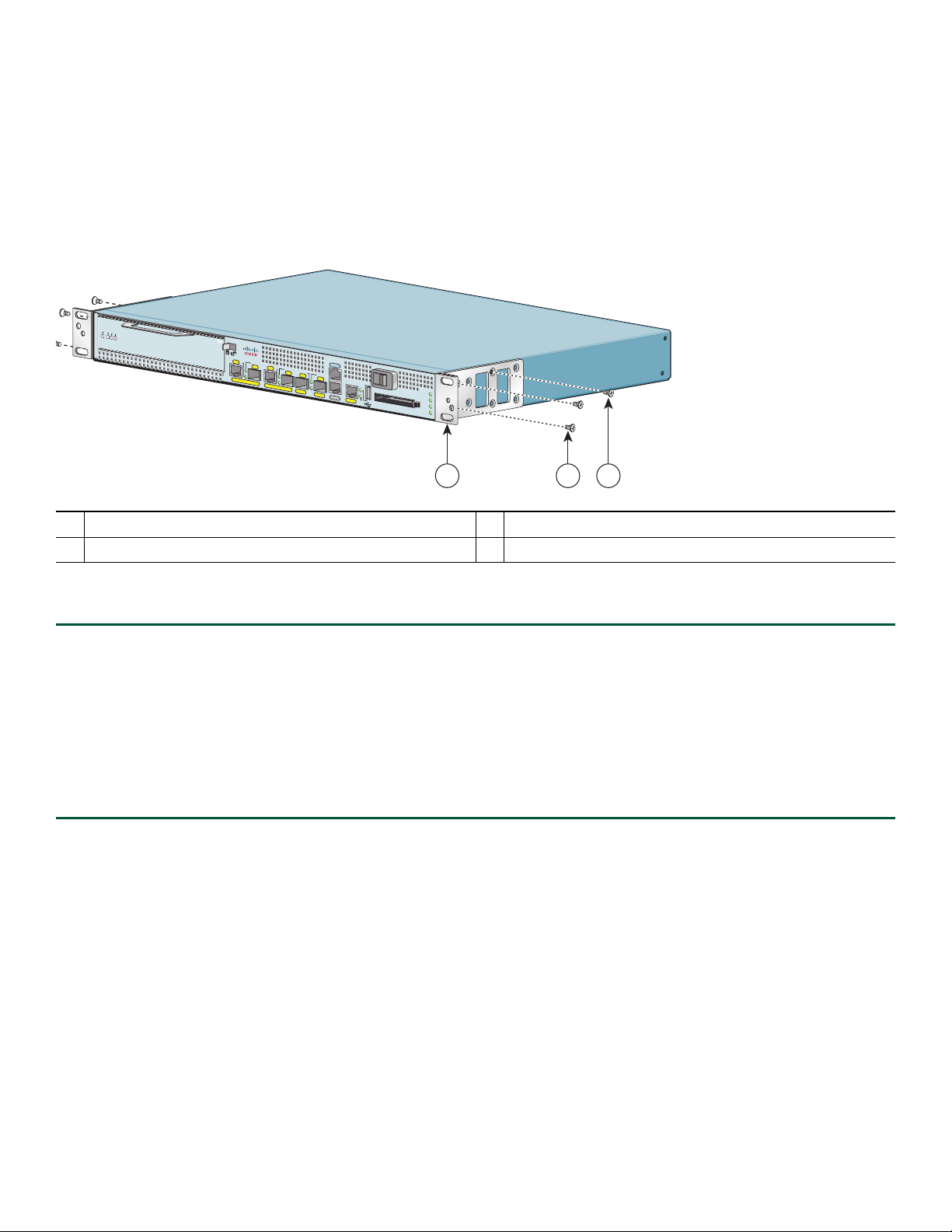
Attach the Rack-Mount Brackets—Chassis Front-Mounted
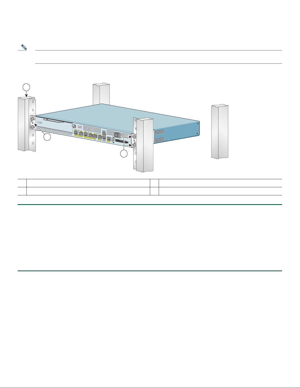
Figure 1 Attaching the Rack-Mount Brackets to the Front of the Chassis
LED
B
A
N
E
RX CELLS
RX CARRIER
RX ALARM
ATM
C
is
c
o
72
0
1
R
J45
EN
LINK
/ACTV
SFP
RJ45
EN
PA
SLOT 1
TX
GE 0/0
GE
0/1
CO
NSO
LINK/ACTV
SFP
LE
LINK
/ACTV
RX
LINK/ACTV
SFP
TX
SFP
RX
MNGM
NT USE ONL
G
E 0/2
Y
GE 0/3
AU
X
FE 0/0
0
FE
LINK
A
LARM
PW
R O
K
STATUS
CO
MPA
CT FLASH
CF
A
CT
V
2 31
281124
Rack-mount bracket
1
Four 6-32 x 0.25-in. screws
2
Two M3 x 8-mm screws
3
To install the rack-mount brackets on a Cisco 7201 router for a front rack-mount configuration, complete the following steps:
Step 1 Locate the threaded holes in the front sides of the chassis.
Step 2
Step 3
Align the rack-mount bracket to the rack-mount bracket holes on the side of the router.
Remove any existing cover screws from the front sides of the chassis that align with the rack-mount bracket holes and
then realign the bracket. (You should have to remove one cover screw from each side of the chassis.)
Step 4 Insert and tighten two 6-32 x 0.25-in. screws in the two holes nearest the front of the chassis.
Step 5 Insert and tighten the longer M3 x 8-mm screw in the hole nearest the rear of the chassis. (This screw replaces the cover
screw that you removed in Step 3.)
Step 6 Repeat Step 1 through Step 5 on the other side of the router.
To install the cable-management bracket, see page 7. If you are not installing the cable-management bracket, skip to the
“Two-Post Rack Installation” section on page 8 or the “Four-Post Rack Installation” section on page 9 for rack-mount
instructions.
5
Page 6
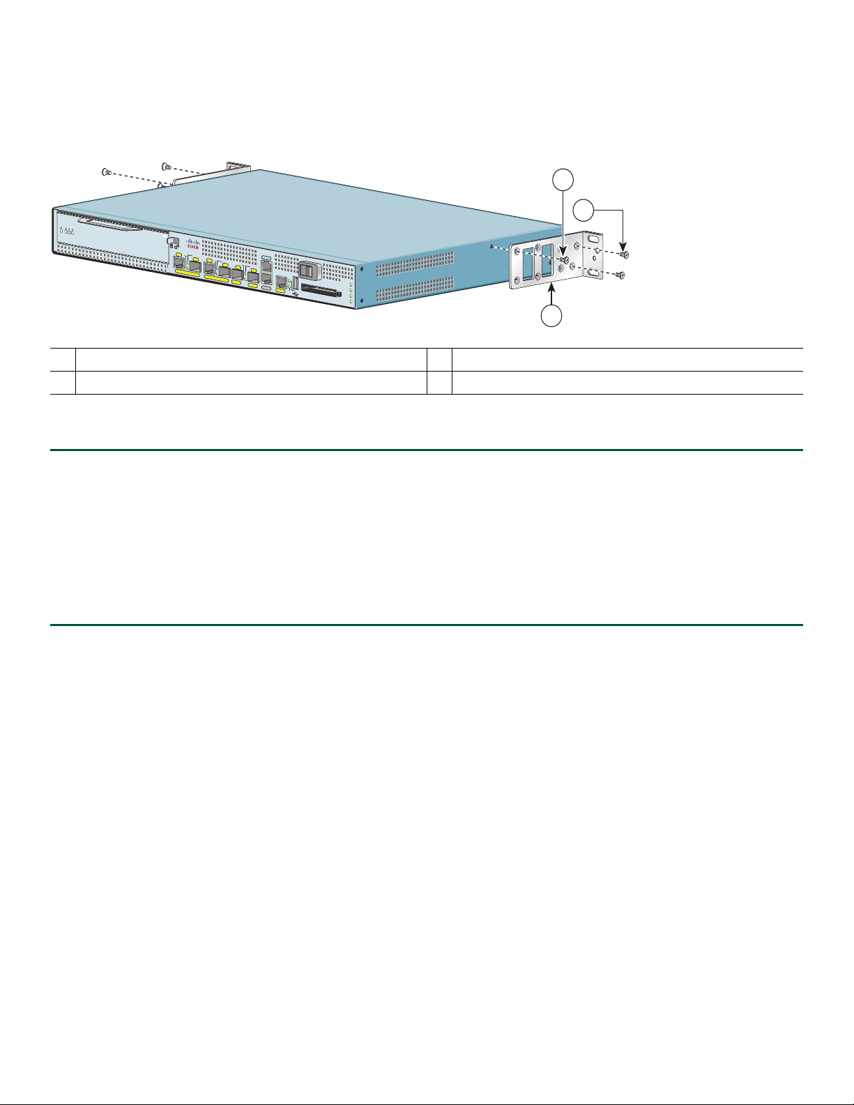
Attach the Rack-Mount Brackets—Chassis Rear-Mounted
Figure 2 Attaching the Rack-Mount Brackets to the Rear of the Chassis
3
R
S
IE
L
M
R
L
R
R
E
A
A
L
C
C
X
ENABLED
A
X
R
X
R
R
Rack-mount bracket
1
Four 6-32 x 0.25-in. screws
2
A
TM
R
P
A
S
L
O
T
1
Cisco 7201
J
4
5
E
N
L
IN
K
/A
C
T
V
S
F
P
R
J
4
5
E
N
T
G
E
0
/0
G
E
0
/1
C
O
N
S
O
L
L
IN
K
/A
C
X
S
F
P
E
T
V
L
IN
K
/A
C
T
V
R
X
L
IN
S
K
F
/A
P
C
T
V
T
X
S
F
P
R
X
M
N
G
M
N
T
U
S
E
O
N
L
G
E
0
/2
Y
G
E
0
/3
A
U
X
F
E
0
0
/0
F
E
L
IN
K
A
L
A
R
M
P
W
R
O
K
S
T
A
T
U
S
C
O
M
P
A
C
T
FL
A
SH
C
F
A
C
T
V
Two M3 x 8-mm screws
3
2
1
281125
To install the rack-mount brackets on a Cisco 7201 router for a rear rack-mount configuration, complete the following steps:
Step 1 Locate the threaded holes in the rear sides of the chassis.
Step 2
Step 3
Align the rack-mount bracket to the rack-mount bracket holes on the side of the router.
Remove any existing cover screws from the sides of the chassis that align with the rack-mount bracket holes and then
realign the bracket. (You should have to remove one cover screw from each side of the chassis.)
Step 4 Insert and tighten two 6-32 x 0.25-in. screws in the two holes nearest the rear of the chassis.
Step 5 Insert and tighten the longer M3 x 8-mm screw in the hole nearest the front of the chassis. (This screw replaces the cover
screw that you removed in Step 3.)
Step 6 Repeat Step 1 through Step 5 on the other side of the router.
To install the cable-management bracket, see page 7. If you are not installing the cable-management bracket, skip to the
“Two-Post Rack Installation” section on page 8 or the “Four-Post Rack Installation” section on page 9 for rack-mount
instructions.
6
Page 7
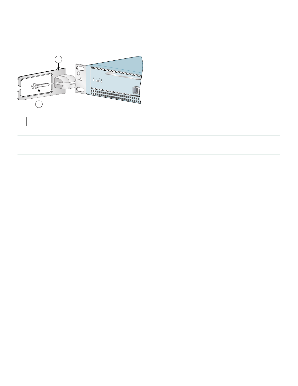
Attach the Cable-Management Bracket
Figure 3 Installing the Cable-Management Bracket
1
ENABLED
RX CELLS
RX CARRIER
RX ALARM
2
170862
1 Cable-management bracket 2 M4 x 20-mm screw
Step 1 Align the cable-management bracket to the rack-mount bracket on the left side of the Cisco 7201 router.
Step 2 Using a Phillips screwdriver and the
M4 x 20-mm screw, thread and tighten the screw to the cable-management bracket.
This completes the procedure for installing the cable-management bracket on a Cisco 7201 router. Go to the “Two-Post Rack
Installation” section on page 8 or the “Four-Post Rack Installation” section on page 9.
7
Page 8
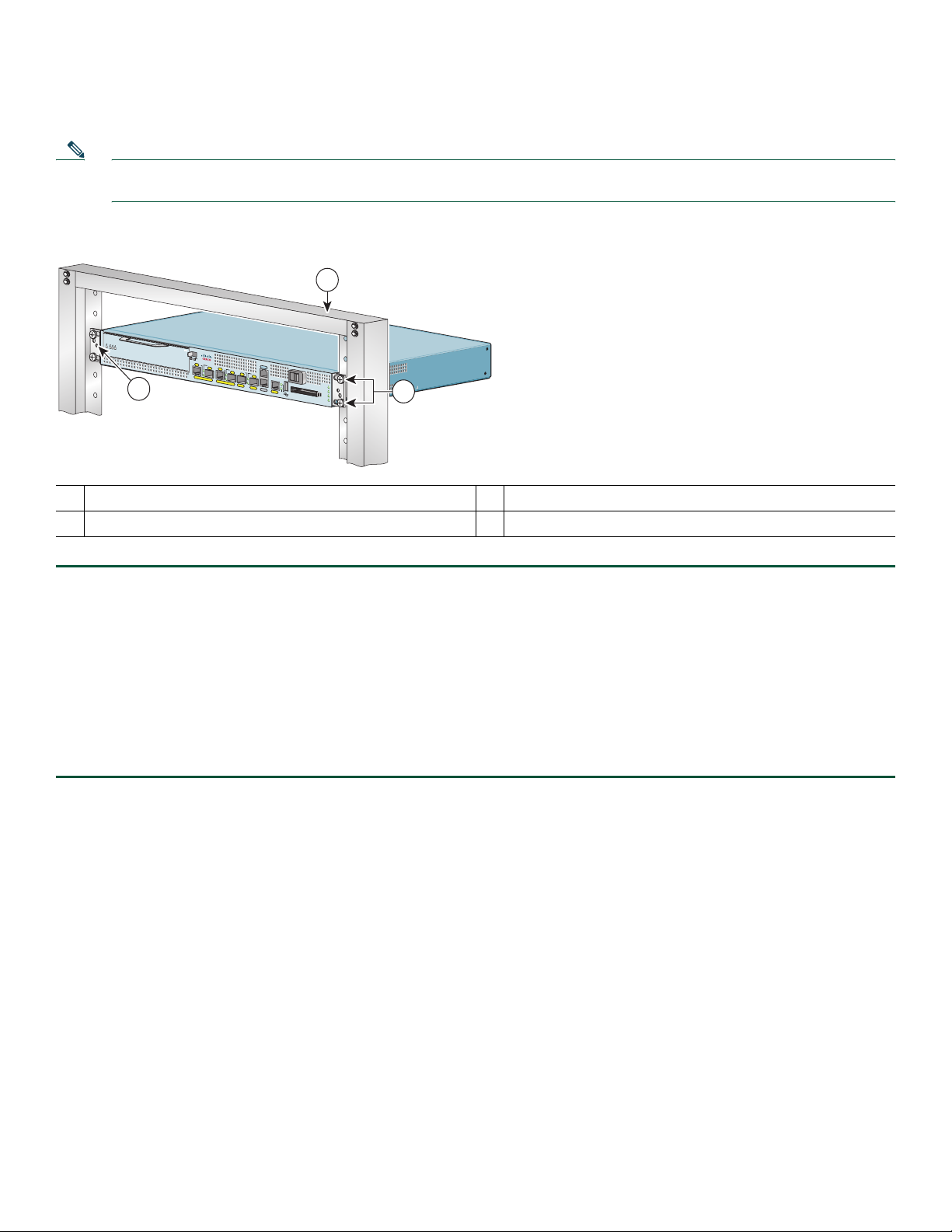
Two-Post Rack Installation
Note Inner clearance (the width between the inner sides of the two posts or rails) must be at least 19 inches (48.26 cm). The
height of the chassis is 1.73 inches (4.39 cm). Airflow through the chassis is from front to back.
Figure 4 Installing the Cisco 7201 Router in a Two-Post Rack
1
IER
M
CELLS
ENABLED
X CARR
RX
X ALAR
R
R
ATM
C
is
c
o
7
2
0
1
R
J
4
5
E
N
L
I
N
K
/A
C
T
V
S
F
P
P
A
S
LO
T
1
G
E
0
/0
2
C
O
N
S
O
L
R
E
J
4
5
E
N
L
I
N
K
/A
C
T
V
L
IN
K
T
/A
X
C
S
F
T
P
V
R
X
L
I
N
S
K
F
/A
P
C
T
V
T
X
S
F
P
R
X
M
N
G
M
N
T
U
S
E
O
N
L
G
E
0
/1
Y
G
E
0
/2
G
E
0
/3
A
U
X
F
E
0
A
L
A
R
M
P
W
R
O
K
0
/0
F
E
L
IN
K
S
T
A
T
U
S
C
O
M
P
A
C
T
F
L
A
S
H
C
F
A
C
T
V
3
281126
Two-post rack
1
Screw hole for the cable-management bracket
2
Four 10-32 or 12-24 screws
3
Step 1 Make sure that the port adapter lever is in the locked position.
Step 2 Make sure the rack brakes are locked or the rack is stabilized.
Step 3 Position the router so the front is closest to you and lift it carefully into the rack. To prevent injury, avoid any sudden
twists or moves.
Step 4 Slide the chassis into the rack, pushing it back until the brackets meet the mounting strips or posts on both sides of the
rack.
Step 5 Keeping the brackets flush against the posts or mounting strips, align the holes in the brackets with the holes on the
rack or mounting strip.
Step 6 For each bracket, insert and tighten two 10-32 or 12-24 screws to the rack.
This completes the procedure for installing the chassis in the rack. Proceed to the “Chassis Ground Connection Installation”
section on page 10 to continue the installation.
8
Page 9
Four-Post Rack Installation
Note Inner clearance (the width between the inner sides of the two posts or rails) must be at least 19 inches (48.26 cm). The
height of the chassis is 1.73 inches (4.39 cm). Airflow through the chassis is from front to back.
Figure 5 Installing the Cisco 7201 Router in a Four-Post Rack
1
D
E
L
B
ARRIER
CELLS
LARM
NA
C
X
E
R
X A
RX
R
2
A
T
M
Cisco 7201
R
J4
5
E
N
L
IN
K
/A
C
TV
S
FP
R
J4
5
P
A
S
LO
EN
T 1
G
E
0
/0
G
E
0/1
C
O
N
SO
LE
L
IN
K
/A
C
TV
LIN
K
T
/A
X
C
S
FP
TV
R
X
LIN
S
K
F
/AC
P
TV
TX
S
F
P
R
X
M
N
GM
N
T U
S
E
ON
L
G
E
0/2
Y
G
E 0
/3
A
U
X
FE
0/0
0
F
E
LIN
K
COMPACT FLASH
A
LA
R
M
P
W
R
O
K
ST
A
TU
S
C
F
A
C
T
V
3
281127
Four-post rack
1
Screw hole for the cable-management bracket
2
Four 10-32 or 12-24 screws
3
Step 1 Make sure that the port adapter lever is in the locked position.
Step 2 Make sure the rack brakes are locked or the rack is stabilized.
Step 3 Position the router so the front is closest to you and lift it carefully into the rack. To prevent injury, avoid any sudden
twists or moves.
Step 4 Slide the chassis into the rack, pushing it back until the brackets meet the mounting strips or posts on both sides of the
rack.
Step 5 Keeping the brackets flush against the posts or mounting strips, align the holes in the brackets with the holes on the
rack or mounting strip.
Step 6 For each bracket, insert and tighten two 10-32 or 12-24 screws to the rack.
This completes the procedure for installing the chassis in the rack. Proceed to the “Chassis Ground Connection Installation”
section on page 10 to continue the installation.
9
Page 10
Chassis Ground Connection Installation
Before you connect power or turn on power to your router, you must provide an adequate chassis ground (earth) connection
for the router chassis. A chassis ground connector is provided on each Cisco 7201 router chassis.
Figure 6 Locating the Chassis Ground Connector
T
H
IS
U
N
IT
M
A
Y
H
A
V
E
M
O
R
E
T
H
A
N
O
N
E
P
O
W
E
R
S
U
P
P
L
Y
C
O
N
N
E
C
T
IO
N
. A
L
L
C
O
N
N
E
C
T
IO
N
S
M
U
S
T
B
E
R
E
M
O
V
E
D
T
O
D
E
-E
N
E
R
G
IZ
E
T
H
E
U
N
IT
PWR
SLOT 1 OK
PWR
SLOT 2 OK
PWR
SLOT 1
PWR
1
2
1 Fan vents 2 Chassis ground connector
Step 1 Use the wire stripper to strip one end of the 6-AWG wire approximately 0.75 inches (19.05 mm).
Step 2 Insert the 6-AWG wire into the wire receptacle on the grounding lug.
Step 3 Use the crimping tool to carefully crimp the wire receptacle around the wire; this step is required to ensure a proper
mechanical connection.
SLOT 2
170934
Figure 7 Attaching the Grounding Lug
T
H
IS
U
N
IT
M
A
Y
H
A
V
E
M
O
R
E
T
H
A
N
O
N
E
P
O
W
E
R
S
U
P
P
L
Y
C
O
N
N
E
C
T
IO
N
. A
L
L
C
O
N
N
E
C
T
I
O
N
S
M
U
S
T
B
E
R
E
M
O
V
E
D
T
O
D
E
-E
N
E
R
G
I
Z
E
T
H
E
U
N
IT
PWR
SLOT 1 OK
PWR
SLOT 2 OK
PWR
SLOT 1
PWR
1
SLOT 2
230031
1 Grounding lug
Step 4 Attach the grounding lug with the wire on the left so the grounding wire does not overlap the power supply.
10
Page 11
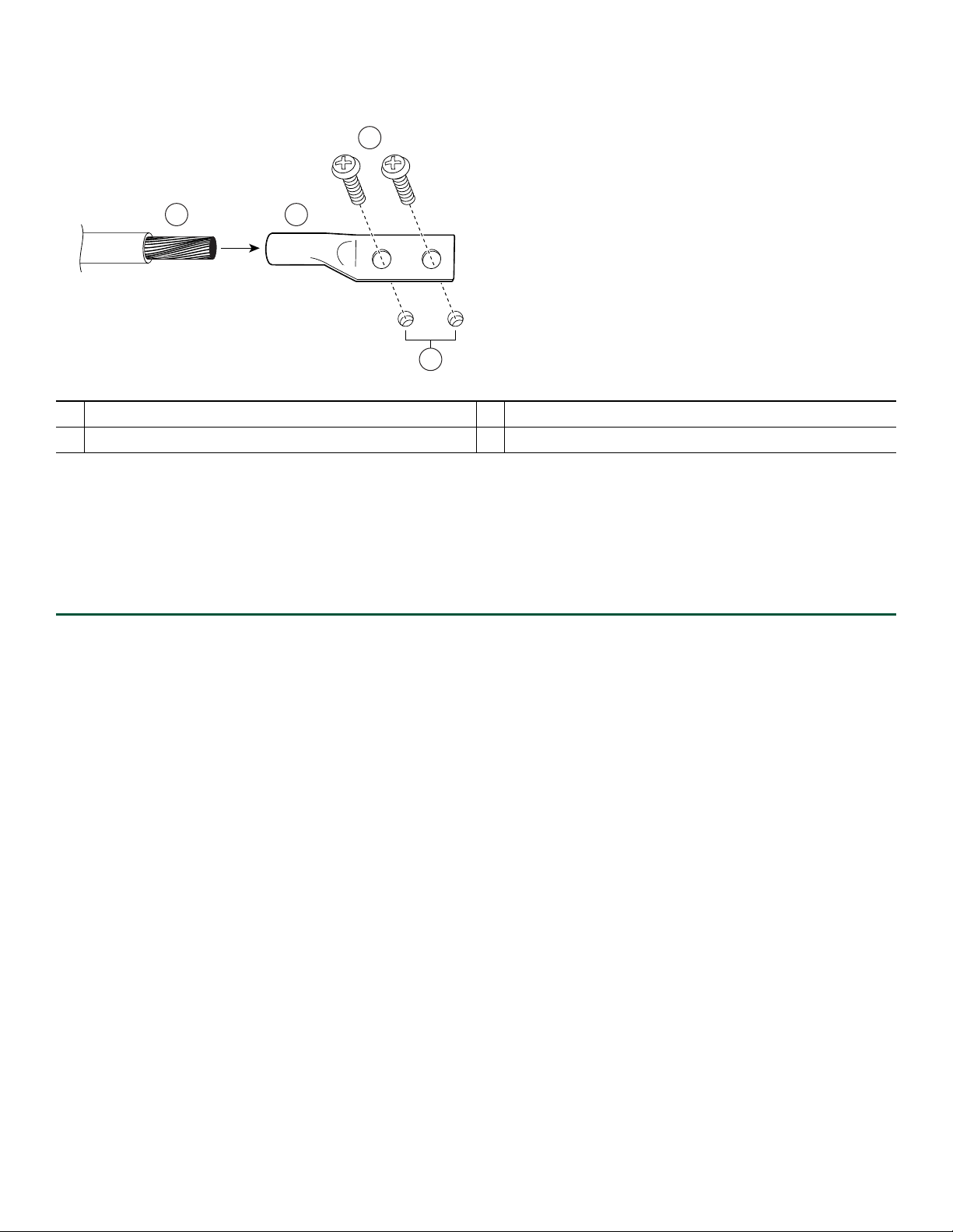
Figure 8 Attaching a Grounding Lug to the Chassis Ground Connector
3
4
2
50536
1
1 Chassis ground connector 3 Screws
2 Grounding lug 4 Wire
Step 5 Locate the chassis ground connector on the rear of your router chassis.
Step 6 Insert the two screws through the holes in the grounding lug.
Step 7 Use the Number 2 Phillips screwdriver to carefully tighten the screws until the grounding lug is held firmly to the
chassis. Do not overtighten the screws.
Step 8 Connect the opposite end of the grounding wire to the appropriate grounding point at your site to ensure an adequate
chassis ground.
This completes the procedure for attaching a chassis ground connection. Go to the “Connect the Router to the Network” section
on page 12 for information on attaching cables.
11
Page 12
4 Connect the Router to the Network
This section provides information about cables and ports and attaching the router to the network.
• Console and Auxiliary Port Cable Connections, page 12
• Connect the Fast Ethernet Management Port Cable, page 14
• Connect Native Gigabit Ethernet Cables, page 14
• Connect the Port Adapter Cables, page 18
• Install the Cables in the Cable-Management Bracket, page 19
Warning
The ports labeled “Ethernet,” “10BaseT,” “Token Ring,” “Console,” and “AUX” are safety extra-low voltage (SELV)
circuits. SELV circuits should only be connected to other SELV circuits. Because the BRI circuits are treated like
telephone-network voltage, avoid connecting the SELV circuit to the telephone network voltage (TNV) circuits.
Statement 22
Console and Auxiliary Port Cable Connections
Figure 9 Console and Auxiliary Port RJ-45 Connectors
2
Cisco
7201
RJ45
EN
LINK/A
CTV
SFP
G
E 0/0
Auxiliary port
1
Console port
2
RJ-45 connector
3
RJ45
EN
LIN
K/ACTV
LINK/A
TX
CTV
SFP
RX
SFP
G
E 0/1
G
4
E 0/2
5
CO
NSO
LE
LINK/A
CTV
TX
SFP
RX
M
N
G
M
NT U
SE O
N
LY
GE
0/3
AU
X
FE 0/0
0
3
FE
LIN
K
COMPACT FLASH
1
A
PW
STATUS
LARM
AC
R O
K
CF
TV
170866
4
5
Cable to console terminal or DTE
Cable to modem or DCE
Step 1 Before connecting a terminal to the console port, configure the terminal to match the router console port as follows:
9600 baud, 8 data bits, no parity, 1 stop bits (9600 8N1).
Step 2 After you establish normal router operation, you can disconnect the terminal.
The Cisco 7201 router uses RJ-45 ports for both the auxiliary port and the console port.
Note You must supply your own interface cable between the auxiliary port and the equipment you are connecting. For
console and auxiliary port pinouts, see Appendix A, “Specifications,” of the online Cisco 7201 Installation and
Configuration Guide.
12
Page 13
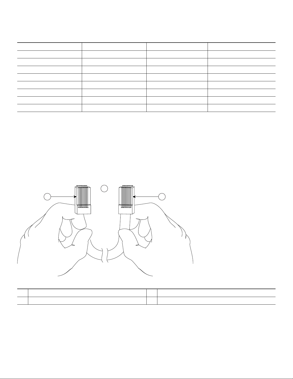
Table 1 Pinouts for the RJ-45-to-DB-25 Adapters
Adapter DTE M/F Pins
1
DCE M/F Pins MMOD Pins
2
1455
22068
3233
4777
5777
6322
762020
8544
1. The female data terminal equipment (FDTE) adapter that is available from Cisco is labeled “Terminal”.
2. The MMOD adapter that is available from Cisco is labeled “Modem”.
Refer to Table 1 for a list of the pins used on the RJ-45-to-DB-25 adapters, used with an RJ-45 cable, to connect terminals and
modems to the Cisco 7201 router. The cable you use may be a roll-over cable or a straight-through cable.
A roll-over cable can be detected by comparing the two modular ends of the cable. Holding the cables in your hand, side-by-side,
with the tab at the back, the wire connected to the pin on the outside of the left plug should be the same color as the pin on the
outside of the right plug. If your cable was purchased from Cisco, pin 1 will be white on one connector, and pin 8 will be white
on the other (a roll-over cable reverses pins 1 and 8, 2 and 7, 3 and 6, and 4 and 5). (See Figure 10.)
Figure 10 Identifying a Roll-Over Cable
2
1 3
84532
Pin 1
1
Pin 1 and pin 8 should be the same color
2
Pin 8
3
The Cisco 7201 router ships with a roll-over cable. Connection to a terminal or a modem will require an RJ-45-to-DB-25
adapter, and possibly a DB-25-to-DB9 adapter. Refer to Table 2 for the cable and adapter configurations that can be used to
connect terminals and modems to the Cisco 7201 router.
13
Page 14
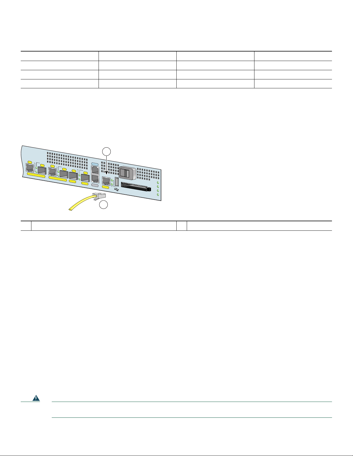
Table 2 Asynchronous Device Cabling Options
Access Server Port RJ-45 Cable Type DB-25 Adapter End Device
Console or auxiliary Roll-over FDTE
1
Termina l
Console or auxiliary Straight-through FDCE Terminal
Auxiliary or console Roll-over MMOD
1. The FDTE RJ-45-to-DB-25 adapter is labeled “Terminal”.
2. The MMOD RJ-45-to-DB-25 adapter is labeled “Modem”.
2
Modem
Connect the Fast Ethernet Management Port Cable
Figure 11 Installing the Fast Ethernet Management Port Cable
1
R
J4
5
E
N
L
IN
K
/A
C
T
V
S
F
P
R
J45
E
N
L
IN
K
/A
C
T
V
L
IN
K
/A
T
X
C
S
F
P
R
X
S
G
E
0/0
G
FP
E
0/1
G
E
0/2
C
O
N
S
O
L
T
V
E
L
IN
K
/A
C
T
V
T
X
S
F
P
R
X
M
N
G
M
N
T
U
S
E
O
N
L
Y
G
E
0/3
A
U
X
F
E
0/0
0
F
E
LIN
K
COMPACT FLASH
A
L
A
R
M
P
W
R
O
K
S
T
A
T
U
S
C
F
A
C
T
V
170868
2
Fast Ethernet Management port
1
RJ-45 Fast Ethernet cable
2
When using the Fast Ethernet Management port in the default mode (speed-auto and duplex-auto) the port operates in
auto-MDI/MDI-X mode. The port automatically provides the correct signal connectivity through the Auto-MDI/MDI-X feature.
The port automatically senses a crossover or straight-through cable and adapts to it.
However, when the Fast Ethernet Management port is configured to a fixed speed (10 or 100 Mbps) through command-line
interface (CLI) commands, the port is forced to MDI mode.
When in a fixed-speed configuration and MDI mode:
• Use a crossover cable to connect to an MDI port
• Use a straight-through cable to connect to an MDI-X port
Connect Native Gigabit Ethernet Cables
The Cisco 7201 router native Gigabit Ethernet ports use either optical fiber or RJ-45 Ethernet cables. For installation
information see:
• Install the SFP Module Optical Fiber Cables, page 15
• Install the Native Gigabit RJ-45 Ethernet Cables, page 18
The SFP port is a 1000-Mbps optical interface in the form of an LC-type duplex port that supports IEEE 802.3z interfaces
compliant with the 1000BASEX standard. (See Figure 13.)
Appendix A, “Specifications” of the online Cisco 7201 Installation and Configuration Guide, provides cabling specifications
and configuration information for the SFP modules that you install in the Gigabit Ethernet SFP ports.
Warning
14
Because invisible laser radiation may be emitted from the aperture of the port when no cable is connected, avoid
exposure to laser radiation and do not stare into open apertures.
Statement 70
Page 15
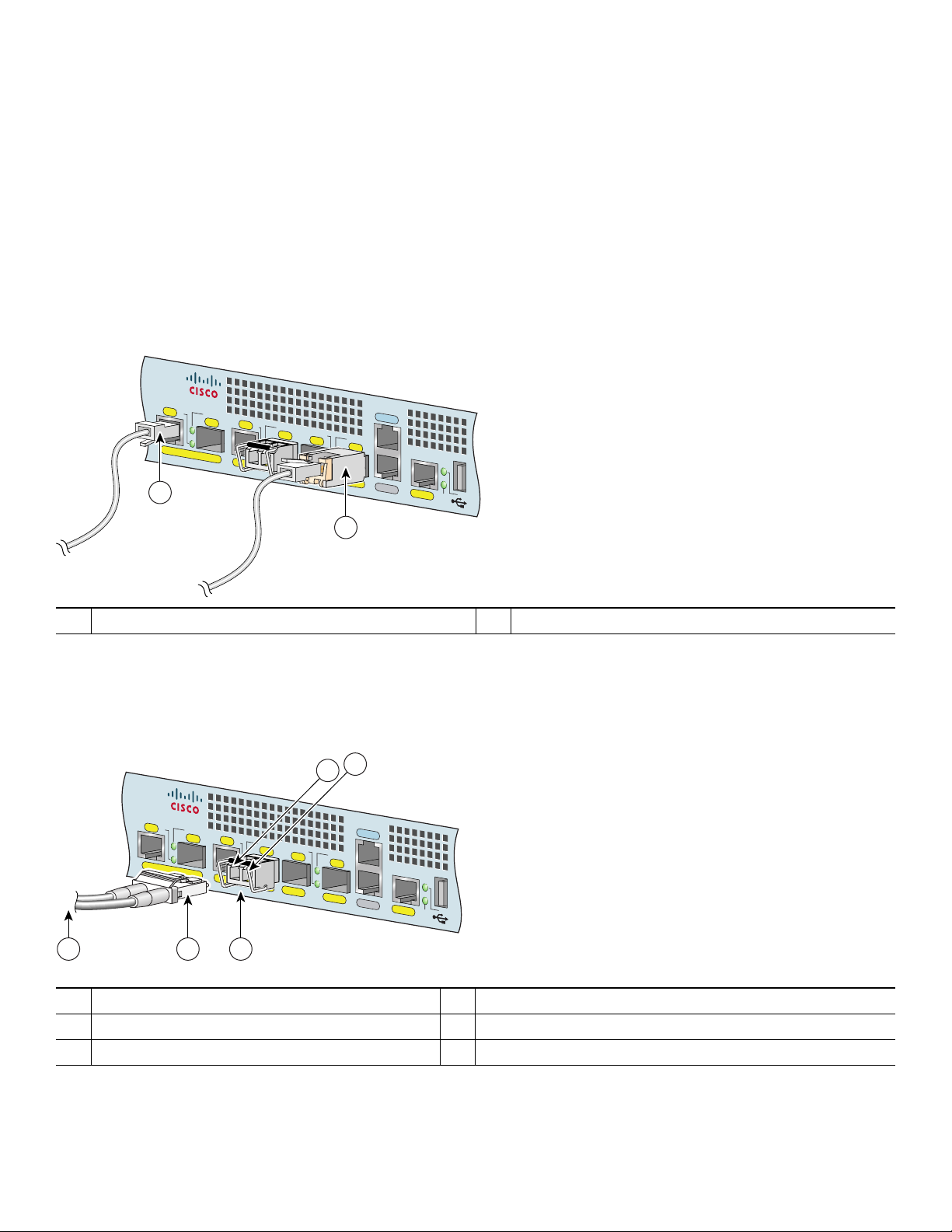
Figure 13 shows the duplex LC-type connectors on your multimode or single-mode optical fiber cables. For simplex connectors,
two cables are required, one cable for transmit (TX) and a second cable for receive (RX). For duplex connectors, only one cable
that has both TX and RX connectors is required. You can use either simplex or duplex connectors to the SFP ports on the
Cisco 7201 router.
Install the SFP Module Optical Fiber Cables
The SFP module ports support IEEE 802.3z (optical Gigabit Ethernet) interfaces compliant with 1000BASESX and
1000BASELX specifications.
SFP modules ordered with the Cisco 7201 router come installed in the system. Optical fiber cables are commercially available;
they are not available from Cisco.
Figure 12 Optical SFP Modules and Copper SFP Modules
Cisco
7201
RJ45
EN
LINK/ACTV
SFP
RJ45
EN
LINK/ACTV
LINK/ACTV
TX
SFP
RX
GE 0/0
GE 0/1
SFP
GE 0/2
1
TX
2
LINK/ACTV
SFP
GE 0/3
RX
CONSOLE
AUX
MNGMNT USE ONLY
FE 0/0
LINK
0
FE
230316
1 RJ-45 cable 2 Copper SFP module RJ-45 connector
The optical SFP modules can occupy any of the four optical Gigabit Ethernet ports, 0/0 through 0/3. However, the copper SFP
modules can occupy only optical Gigabit Ethernet ports 0/2 and 0/3.
Figure 13 SFP Port Connections
5
4
Cisco
7201
RJ45
EN
GE 0/0
LINK/ACTV
SFP
RJ45
EN
GE 0/1
TX
LINK/ACTV
SFP
LINK/ACTV
RX
SFP
GE 0/2
TX
LINK/ACTV
SFP
GE 0/3
CONSOLE
RX
MNGMNT USE ONLY
AUX
FE 0/0
0
FE
LINK
170869
1 32
To external 1000BASEX network
1
Duplex connector (TX and RX)
2
SFP module
3
TX (SFP port 0/1)
4
RX (SFP port 0/1)
5
15
Page 16

Note We strongly recommend cleaning optical fiber connections before attaching cables to equipment. For information about
cleaning fiber-optic cable connectors and receptacles, see the Inspection and Cleaning Procedures for Fiber-Optic
Connections document. It provides detailed illustrations and photos of procedures and equipment required to properly clean
fiber-optic connections. Also see the Compressed Air Cleaning Issues for Fiber-Optic Connections document.
Warning
Warning
Step 1 Remove the plug from the SFP module so that you can insert the optical fiber cables. Keep the plug for use should you
Warning
Step 2 Attach the appropriate optical fiber cable directly to the SFP module. You can use either simplex or duplex connectors
Caution If you plan to use a SFP-GE-L at distances greater than 984.25 feet (300 meters) over 50/125-micron or
Class 1 laser product.
Class 1 LED product.
ever disconnect the optical fiber cables.
Invisible laser radiation may be emitted from disconnected fibers or connectors. Do not stare into beams or view
directly with optical instruments.
for most devices. (Figure 13 shows an SFP module with a duplex connector being installed in SFP port 0/1.)
• For simplex connectors, two cables are required, one cable for transmit (TX) and a second cable for receive (RX).
• For duplex connectors, only one cable that has both TX and RX connectors is required.
62.5/125-micron multimode fiber, you must use the mode-conditioning patch cord to prevent data transmission
problems.
Statement 1008
Statement 1027
Statement 1051
Mode-Conditioning Patch Cord Description
A mode-conditioning patch cord can be used with the SFP-GE-L= (SFP module) to allow reliable laser transmission between the
single-mode laser source on the SFP module and a multimode optical fiber cable.
When an unconditioned laser source designed for operation on single-mode optical fiber is directly coupled to a multimode
optical fiber cable, an effect known as differential mode delay (DMD) might result in a degradation of the modal bandwidth of
the optical fiber cable.
This degradation results in a decrease in the link span (the distance between a transmitter and a receiver) that can be supported
reliably. The effect of DMD can be overcome by conditioning the launch characteristics of a laser source. A practical means of
performing this conditioning is to use a device called a mode-conditioning patch cord.
A mode-conditioning patch cord is an optical fiber cable assembly that consists of a pair of optical fibers terminated with
connector hardware. Specifically, the mode-conditioning patch cord is composed of a single-mode optical fiber permanently
coupled off-center (see Offset in Figure 14) to a graded-index multimode optical fiber. Figure 14 shows a diagram of the
mode-conditioning patch cord assembly.
16
Page 17
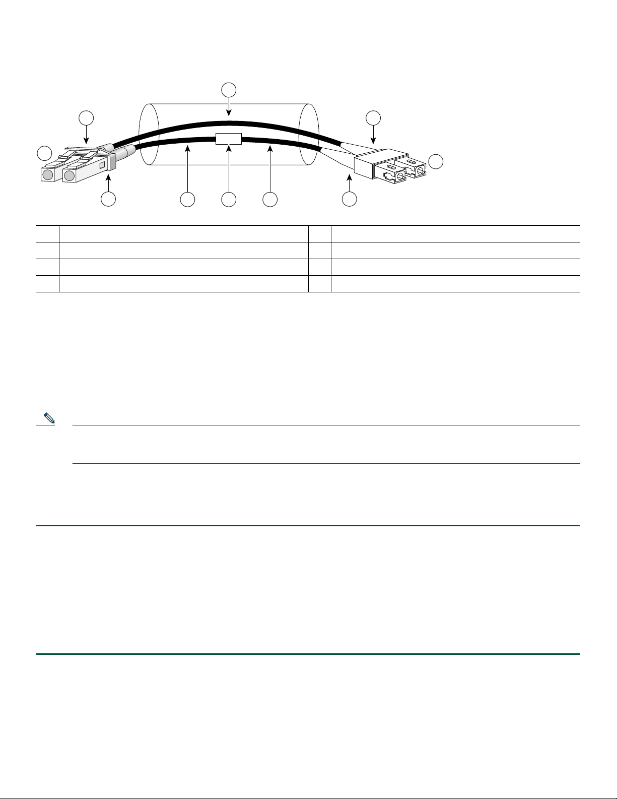
Figure 14 Mode-Conditioning Patch Cord Assembly for an SFP Module
4
1 7
/ /
/ / / /
2
TX
RX
3 7
Gray color identifier
1
To Gigabit Ethernet interface
2
Blue color identifier
3
Multimode bar
4
The mode-conditioning patch cord assembly is composed of duplex optical fibers, including a single-mode-to-multimode offset
launch fiber connected to the transmitter, and a second conventional graded-index multimode optical fiber connected to the
receiver. The use of a plug-to-plug patch cord maximizes the power budget of multimode 1000BASE-LX and 1000BASE-LH
links.
The mode-conditioning patch cord is required to comply with IEEE standards. The IEEE found that link distances could not be
met with certain types of fiber-optic cable cores. The solution is to launch light from the laser at a precise offset from the center,
which is accomplished by using the mode-conditioning patch cord. At the output of the patch cord, the SFP-GE-L= is compliant
with the IEEE 802.3z standard for 1000BASE-LX.
Offset
65 4
Single-mode bar
5
Offset
6
Beige color identifier
7
To cable plant
8
8
84159
Note We strongly recommend cleaning optical fiber connections before attaching cables to equipment. See the Inspection and
Cleaning Procedures for Fiber-Optic Connections document and the Compressed Air Cleaning Issues for Fiber-Optic
Connections document. Figure 14 shows one type of mode-conditioning patch cord.
Attach the Mode-Conditioning Patch Cord
To use a mode-conditioning patch cord, follow these steps:
Step 1 If you have not already done so, and the mode-conditioning patch cord has been in use, we strongly recommend
cleaning optical fiber connections before attaching cables to equipment. For information about cleaning fiber-optic cable
connectors and receptacles, see the Inspection and Cleaning Procedures for Fiber-Optic Connections document and the
Compressed Air Cleaning Issues for Fiber-Optic Connections document.
Step 2 Attach a mode-conditioning patch cord to the SFP module. (See Figure 14.)
Step 3 Attach the network ends of your mode-conditioning patch cord to the appropriate 1000BASEX equipment in your
building cable plant.
Ensure that you connect the TX and RX ports on one end of the patch cord to the RX and TX ports (respectively) on
the other end. Connect TX to RX and RX to TX.
17
Page 18
Install the Native Gigabit RJ-45 Ethernet Cables
This section provides information about installing the native Gigabit Ethernet RJ-45 cables.
Intra-Building Lightning Protection
Shielded cables, which are grounded at both ends, are required to be used on the 10/100/1000 Gigabit Ethernet RJ-45 ports in
order to be in compliance with requirement R4-11 in GR-1089-Core for a Central Office environment. This is not a requirement
for customer premises installations.
Warning
To avoid electric shock, do not connect safety extra-low voltage (SELV) circuits to telephone-network voltage
(TNV) circuits. LAN ports contain SELV circuits, and WAN ports contain TNV circuits. Some LAN and WAN ports
both use RJ-45 connectors. Use caution when connecting cables.
Statement 1021
Connect the Cables
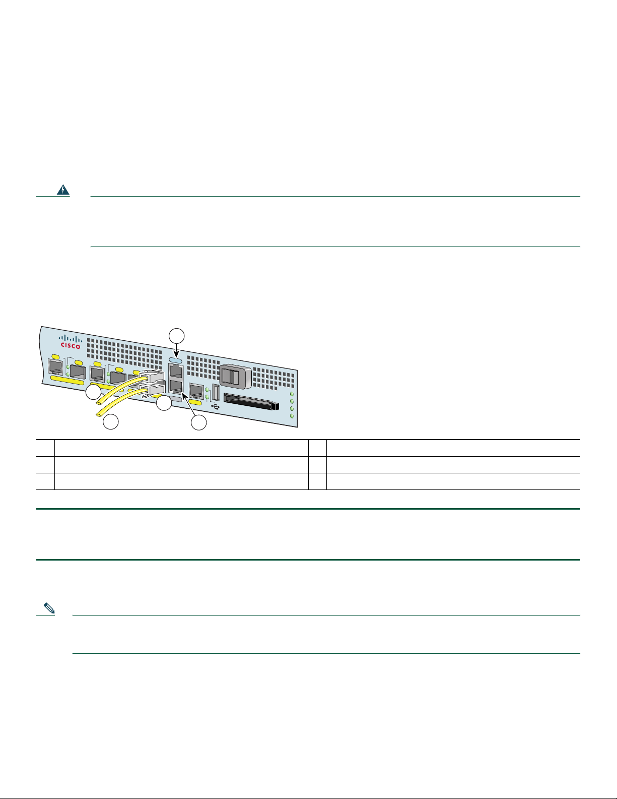
Figure 15 RJ-45 Port and Copper SFP RJ-45 Gigabit Ethernet Port Cabling
Cisco
7201
RJ45
EN
LINK/ACTV
SFP
RJ45
EN
LINK/ACTV
LINK/ACTV
TX
SFP
RX
GE 0/0
GE 0/1
SFP
GE 0/2
1
LINK/ACTV
TX
GE 0/3
CONSOLE
SFP
RX
MNGMNT USE ONLY
AUX
FE 0/0
0
FE
LINK
230316
2
1 RJ-45 connector 2 Copper SFP module
Step 1 Insert an Gigabit Ethernet RJ-45 cable into Gigabit Ethernet RJ-45 ports 0/0 and 0/1 if you are not using Gigabit
Ethernet SFP optical ports 0/0 and 0/1.
Step 2 Insert an Gigabit Ethernet RJ-45 cable into a copper SFP module in Gigabit Ethernet ports 0/2 and 0/3.
.
Connect the Port Adapter Cables
The instructions for connecting the cables for the port adapter installed in the Cisco 7201 router are contained in the respective
configuration notes for each port adapter. For example, if you are connecting the optical fiber cables for the PA-GE port adapter,
refer to the PA-GE Gigabit Ethernet Port Adapter Installation and Configuration document at
http://www.cisco.com/en/US/docs/interfaces_modules/port_adapters/install_upgrade/ethernet/pa-ge_gigabit_ethernet_install_c
onfig/pa_ge.html.
Port adapter documents are also available on the Cisco Documentation DVD.
18
Page 19

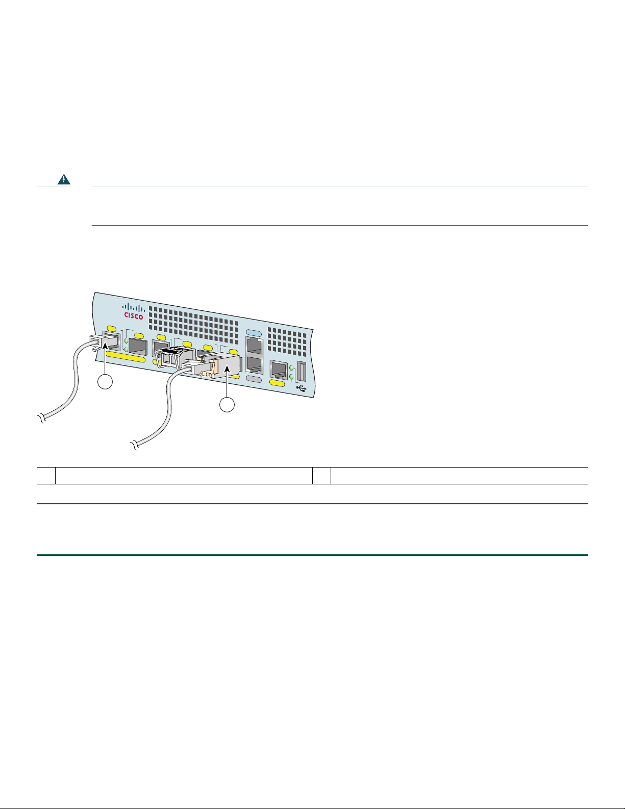
Install the Cables in the Cable-Management Bracket
Figure 16 Securing Interface Cables Through the Cable-Management Bracket
2
R
IE
LS
M
R
L
R
R
E
A
A
L
C
C
X
ENABLED
A
X
R
X
R
R
1 Input/output cables 2 Cable-management bracket
Secure port adapter interface cables and I/O cables by placing them through the cable-management bracket.
Proceed to the “Start the System” section on page 20 to complete the installation.
A
TM
Cisco
7201
RJ45
EN
LINK/ACTV
SFP
RJ45
PA
SLOT 1
EN
GE 0/0
GE 0/1
CONSOLE
LINK/ACTV
LINK/ACTV
TX
SFP
RX
LINK/ACTV
SFP
TX
SFP
RX
MNGMNT USE ONLY
GE 0/2
GE 0/3
AUX
FE 0/0
0
FE
LINK
ALARM
PWR OK
STATUS
C
O
M
PACT
F
LAS
H
CF
ACTV
170870
1
19
Page 20

5 Start the System
Before you start the system, you must connect power to it.
Connect Power to the Router
• If you have AC power supplies, go to the “Connect AC-Input Power” section on page 20.
• If you have DC power supplies, go to the “Connect DC-Input Power” section on page 22.
Warning
Warning
Warning
Warning
Installation of the equipment must comply with local and national electrical codes.
Never install an AC power module and a DC power module in the same chassis.
Statement 1074
Statement 1050
This unit might have more than one power supply connection. All connections must be removed to de-energize the
unit.
Statement 1028
This product relies on the building’s installation for short-circuit (overcurrent) protection. Ensure that the
protective device is rated not greater than: 120 VAC, 20A U.S. (240 VAC, 10A international).
Statement 1005
Connect AC-Input Power
This section provides instructions for installing the AC power supply.
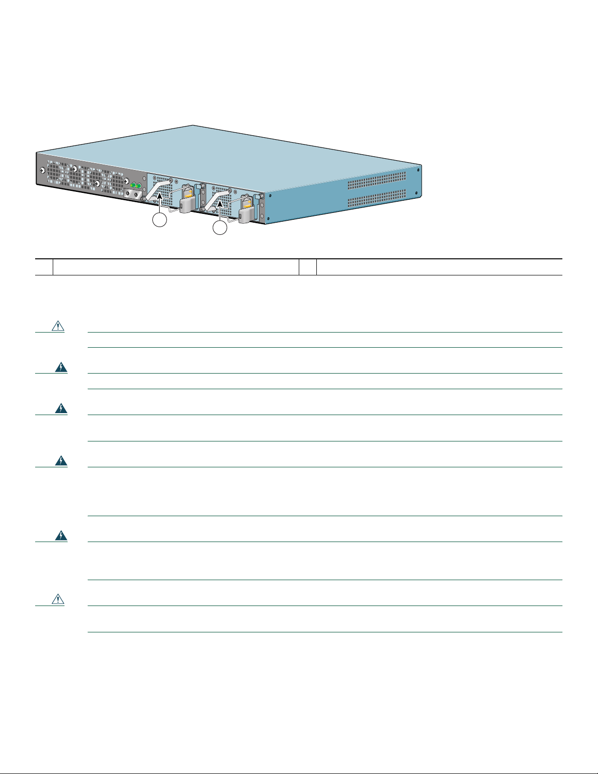
The Cisco 7201 router has two of the same type of power supplies in power supply slot 1 and power supply slot 2. (See
Figure 17.) The power supply slot numbers are on the chassis to the left of the left power supply, and to the right of the right
power supply.
Figure 17 Power Supply Slot 1 and Slot 2
T
H
IS
U
N
IT
M
A
Y
H
A
V
E
M
O
R
E
T
H
A
N
O
N
E
P
O
W
E
R
S
U
P
P
L
Y
C
O
N
N
E
C
T
I
O
N
. A
L
L
C
Power supply slot 1
1
20
O
N
N
E
C
T
I
O
N
S
M
U
S
T
B
E
R
E
M
O
V
E
D
T
O
D
E
E
N
E
R
G
IZ
E
T
H
E
U
N
IT
PWR
SLOT 1 OK
PWR
SLOT 2 OK
PWR
SLOT 1
PWR
1
SLOT 2
230086
2
Power supply slot 2
2
Page 21
Connect an AC-input power supply as follows:
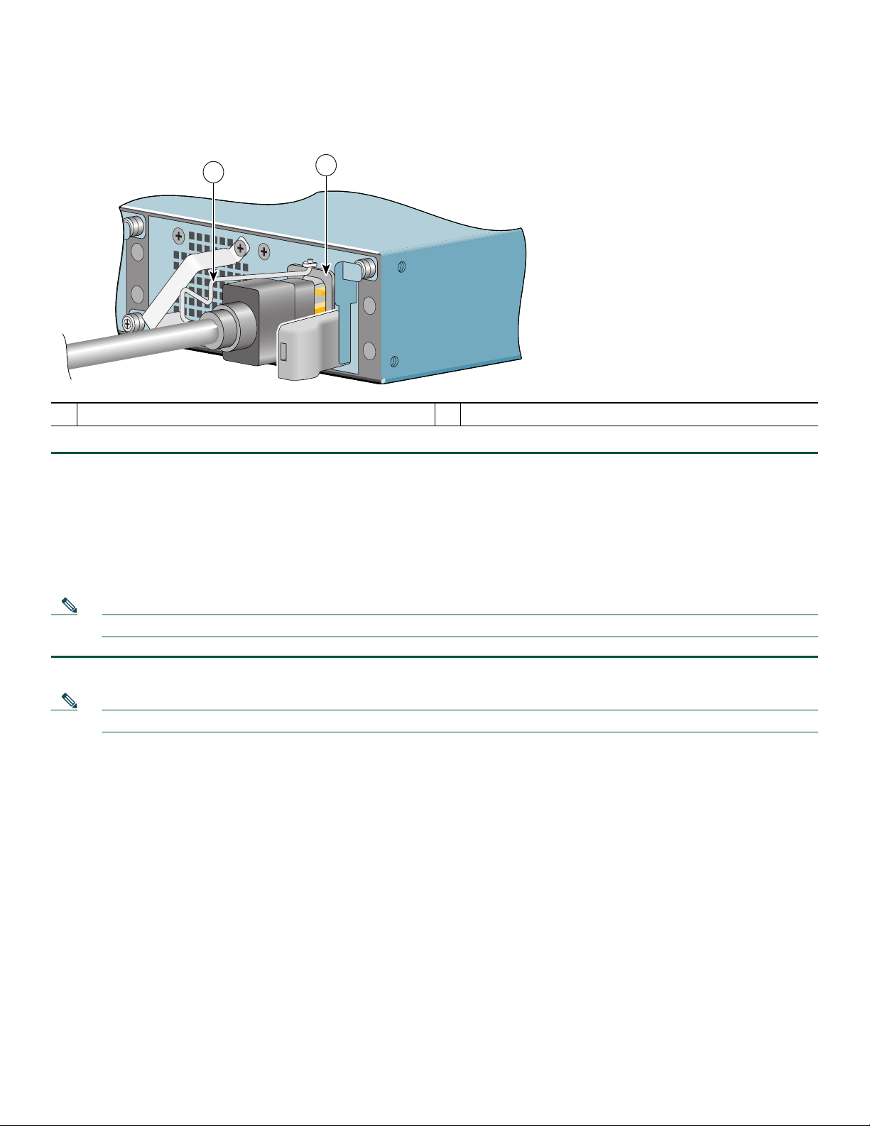
Figure 18 Connecting AC-Input Power
1
PWR
SLOT 2
Adjustable AC power cable-retention clip
2
158677
AC power receptacle
1
2
Step 1 At the front of the router, check that the power switch is in the standby (|) position.
Step 2 Swing the wire cable-retention clip to the left.
Step 3 Plug the power cable into the AC connector of the power supply.
Step 4 Slide the cable-retention clip to the right, so that the power cable is held by the cable-retention clip.
Step 5 Plug the AC power supply cable into the AC power source. Repeat these steps if you have a dual-AC power supply.
Step 6 On the front of the router, place the power switch in on (O) the router to turn on the router.
Note After powering off the router, wait a minimum of 30 seconds before powering it on again.
Note If required, use Sinewave Output UPS (uninterruptable power supply), not Ferro-resonant type UPS.
This completes the procedure for connecting AC-input power. Your installation is complete. Proceed to the “Start the Router”
section on page 29 to start the router and to perform a basic configuration.
21
Page 22
Connect DC-Input Power
This section provides instructions for installing the DC power supply ground leads and installing the DC-input power leads.
Figure 19 Power Supply Slot 1 and Slot 2
T
H
IS
U
N
IT
M
A
Y
H
A
V
E
M
O
R
E
T
H
A
N
O
N
E
P
O
W
E
R
S
U
P
P
L
Y
C
O
N
N
E
C
T
I
O
N
.
A
L
L
C
O
N
N
E
C
T
IO
N
S
M
U
S
T
B
E
R
E
M
O
V
E
D
T
O
D
E
E
N
E
R
G
IZ
E
T
H
E
U
N
I
T
PWR
SLOT 1 OK
PWR
SLOT 2 OK
PWR
SLOT 1
PWR
1
SLOT 2
2
1 Power supply slot 1 2 Power supply slot 2
The Cisco 7201 has two of the same type of power supplies in power supply slot 1 and power supply slot 2. (See Figure 19.)
The power supply slot numbers are on the chassis to the left of the left power supply, and to the right of the right power supply.
Caution Before you connect DC-input power, you must install the DC power ground leads to the DC power supply.
230086
Warning
Warning
Never install an AC power module and a DC power module in the same chassis.
Statement 1050
When installing or replacing the unit, the ground connection must always be made first and disconnected last.
Statement 1046
Warning
Before connecting or disconnecting ground or power wires to the chassis, ensure that power is removed from the
DC circuit. To ensure that all power is OFF, locate the circuit breaker on the panel board that services the DC
circuit, switch the circuit breaker to the OFF position, and tape the switch handle of the circuit breaker in the OFF
Warning
position.
This equipment must be grounded. Never defeat the ground conductor or operate the equipment in the absence of
Statement 140
a suitably installed ground conductor. Contact the appropriate electrical inspection authority or an electrician if
you are uncertain that suitable grounding is available.
Statement 1024
Caution To make sure that the equipment is reliably connected to earth ground, follow the grounding procedure
instructions, and use a UL-listed lug suitable for 6-AWG wire and M5 screws.
Obtain these necessary tools and equipment:
• Ratcheting torque screwdriver with a Phillips head that exerts up to 15 pound force-inches (lbf in.) or 240 ounce
force-inches (ozf in.) of pressure
• Panduit crimping tool with optional controlled cycle mechanism
• 18-gauge copper ground wire (insulated or noninsulated)
22
Page 23

• Four leads of 18-gauge copper wire
• Wire-stripping tool for stripping 18-gauge wire
Install the DC Grounding Leads
To install the DC grounding leads on the DC power supply, follow these instructions.
The DC power supply ships with the DC power supply ground lugs, star washers, and nut attached to the grounding stud on
the DC power supply.
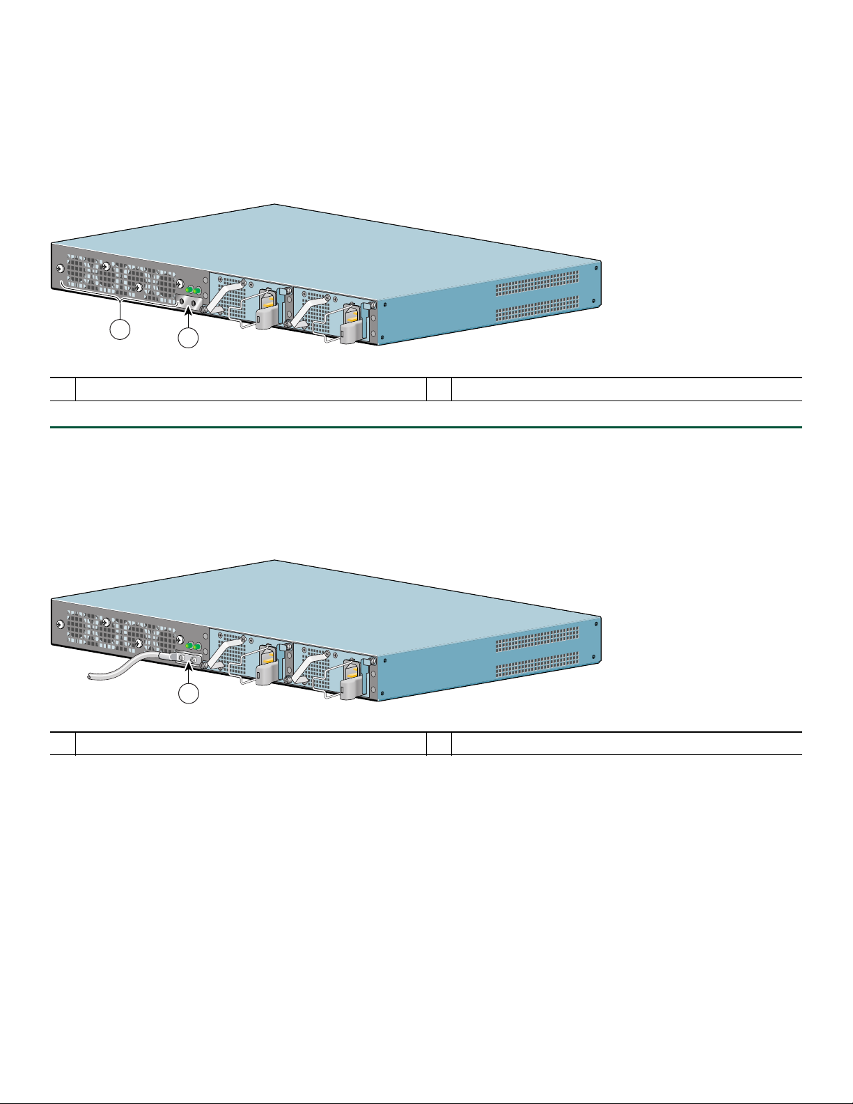
Figure 20 Locating the DC Grounding Stud and Grounding Materials
A
B
PWR
SLOT 2
170976
Step 1 Locate the grounding stud on the DC power supply.
Step 2 Remove the nut, ground lug, star washer, and second ground lug and star washer from the grounding stud.
Figure 21 Stripping the DC-Input Power Ground Wire
1
57019
1 0.5 inch (12.7 mm) + 0.02 inch (0.5 mm)
Step 3 If your ground wire is insulated, use a wire stripping tool to strip the 18-gauge (or 16-gauge, but not smaller than the
supply conductor) ground wire to 0.5 inch (12.7 mm)+ 0.02 inch (0.5 mm) as shown in Figure 21.
Step 4 Slide the open end of the ground lug over the exposed area of the 18-gauge wire.
Step 5 Use a crimping tool to crimp the ground wire to a ground lug.
23
Page 24
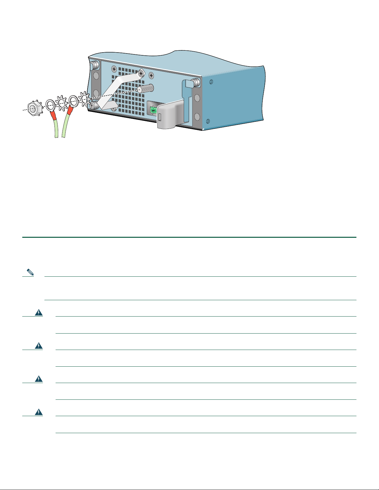
Figure 22 Placing the Ground Lugs, Star Washers, and Nut
A
B
PWR
SLOT 2
170970
Step 6 Place the ground lugs, star washers, and nut on the grounding stud in this order:
a. Star washer
b. Ground lug
c. Star washer
d. Ground lug
e. Nut
Step 7 Tighten the nut to complete the installation.
Step 8 Attach the other end of the ground wires to an appropriate grounding point at your site.
Step 9 Repeat Step 1 through Step 8 on the second DC power supply.
Wire the DC-Input Power Source
Note The color coding of the DC-input power supply leads depends on the color coding of the DC power source at your site.
Make certain the lead color coding you choose for the DC-input power supply matches lead color coding used at the
DC power source.
Warning
Warning
Warning
Warning
When installing or replacing the unit, the ground connection must always be made first and disconnected last.
Statement 1046
This product relies on the building’s installation for short-circuit (overcurrent) protection. Ensure that the
protective device is rated not greater than: 120 VAC, 20A U.S. (240 VAC, 10A international).
Statement 1005
Before performing any of the following procedures, ensure that power is removed from the DC circuit.
Statement 1003
Only trained and qualified personnel should be allowed to install, replace, or service this equipment.
Statement 1030
24
Page 25
Use these instructions to wire the DC-input power source:
Step 1 At the front of the router, make sure the power switch is in the standby (|) position.
Step 2 Move the circuit-breaker switch handle to the off position, and apply tape to hold it in the off position.
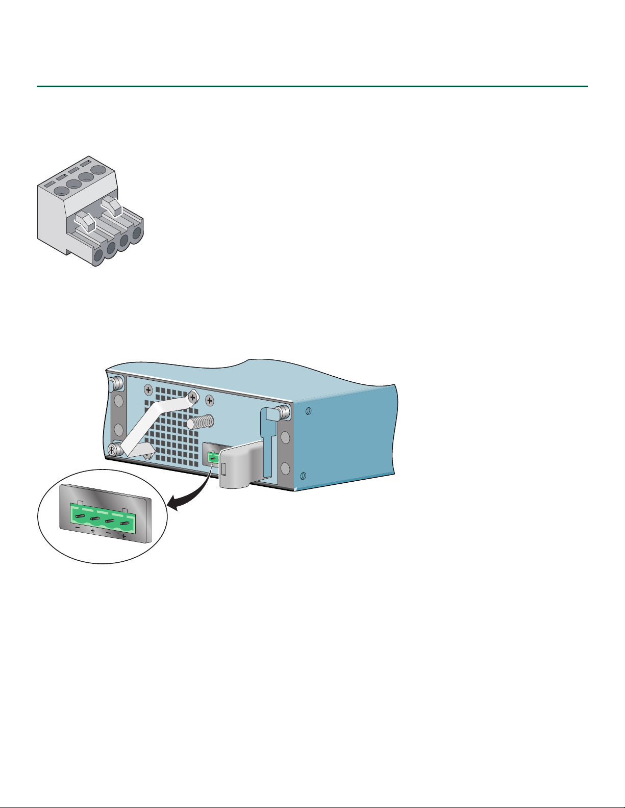
Figure 23 Terminal Block Plug
60530
Step 3 Locate and remove the terminal block plug.
Step 4 Identify the positive and negative feed positions for the terminal block connection. The wiring sequence is positive to
positive and negative to negative for both the A and B feed wires.
Figure 24 Positive and Negative Positions
A
B
A
B
PWR
SLOT 2
170971
The rear panel of the power supply unit identifies the positive and negative positions for both the A and B feed wires.
See Figure 24.
25
Page 26

Figure 25 Stripping the DC-Input Power Source Wire
1
57019
1 0.25 inch (6.3 mm) + 0.02 inch (0.5 mm)
Step 5 Using an 18-gauge wire-stripping tool, strip each of the four wires coming from the DC-input power source to
0.25 inch (6.3 mm) +
0.02 inch (0.5 mm). Do not strip more than 0.29 inch (7.4 mm) of insulation from the wire.
Stripping more than the recommended amount of wire can leave exposed wire from the terminal block plug after
installation.
Warning
Figure 26 Inserting Wires into the Terminal Block Plug
An exposed wire lead from a DC-input power source can conduct harmful levels of electricity. Be sure that no
exposed portion of the DC-input power source wire extends from the terminal block plug.
1
A
2
3
B
4
170975
Statement 122
1 Negative( –) 3 Negative (–)
2 Return (+) 4 Return (+)
Step 6 Insert the exposed wire of one of the four DC-input power source wires into the terminal block plug, as shown in
Figure 26. Make sure that you cannot see any wire lead. Only wire with insulation should extend from the terminal
block.
26
Page 27
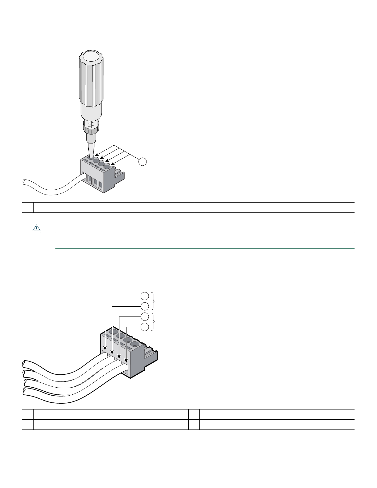
Figure 27 Torquing the Terminal Block Plug Captive Screws
1
170974
1 Torque is from 0.5 Nm (4.425 lbf in.) to 0.6 Nm (5.310 lbf in.)
Caution Do not overtorque the terminal block plug captive screws. The recommended maximum torque is from 0.5 Nm
(4.425 lbf in.) to 0.6 Nm (5.310 lbf in.).
Step 7 Use a ratcheting torque screwdriver to torque the terminal block plug captive screw (above the installed wire lead) to
from 0.5 Nm (4.425 lbf in.) to 0.6 Nm (5.310 lbf in.), as shown in Figure 27.
Figure 28 Completed Wiring of Terminal Block Plug
1
A
2
3
B
4
170972
1 Negative (–) 3 Negative (–)
2 Return (+) 4 Return (+)
Step 8 Repeat Step 6 and Step 7 for the remaining three DC-input power source wires. Figure 28 shows the completed wiring
of a terminal block plug.
27
Page 28

Note Each DC power supply accepts two power feeds, but works with only one. You may choose to install only one power
B
A
feed per power supply. For example, DC power feed A to the power supply in power supply slot 1 and DC power feed
B to the power supply in power supply slot 2.
Figure 29 Inserting the Terminal Block Plug in the Block Header
A
B
PWR
SLOT 2
170973
2
1
1
Tie wrap
Terminal block plug
2
Caution Secure the wires coming in from the terminal block plug so that they cannot be disturbed by casual contact.
Step 9 Use a tie wrap to secure the wires to the rack, so that the wires are not pulled from the terminal block plug by casual
contact. Make sure the tie wrap allows for some slack in the ground wire.
Step 10 Insert the terminal block plug in the terminal block header on the DC power supply panel, as shown in Figure 29.
Step 11 Repeat Step 1 through Step 10 on the second DC power supply.
Step 12 Remove the tape from the circuit-breaker switch handle, and move the circuit-breaker switch handle to the on position.
Step 13 Switch the circuit breaker to the on position.
Step 14 On the front of the router, place the power switch in on (O) the router to turn on the router.
Note After powering off the router, wait a minimum of 30 seconds before powering it on again.
This completes the procedure for connecting DC-input power. Your installation is complete. Proceed to the “Start the Router”
section on page 29 to start the router.
28
Page 29

Start the Router
Check the following conditions before you start your router:
• The port adapter is inserted in its slot and the port adapter lever is in the locked position.
• The network interface cable is connected to the port adapter.
• A CompactFlash Disk is installed.
• SFP modules and their optical-fiber or copper cables are installed.
• The optional USB Flash memory module or Aladdin eToken Pro key is installed.
• The optional Fast Ethernet Management port cable is installed.
• The console terminal is turned on.
Step 1 Place the power switch in the on (O) position.
Step 2 Listen for the fans; they should be operating as soon as power is turned on. The following table provides information
about the LEDs as the system starts.
Figure 30 Cisco 7201 Router—Faceplate LEDs
Cisco
7201
RJ45
EN
LINK/ACTV
SFP
RJ45
EN
LINK/ACTV
LINK/ACTV
TX
SFP
RX
GE 0/0
1
2
GE 0/1
1
2
SFP
GE 0/2
1
1
TX
LINK/ACTV
SFP
GE 0/3
RX
CONSOLE
AUX
MNGMNT USE ONLY
3
FE 0/0
0
FE
LINK
COMPACT FLASH
4
ALARM
PW
STATUS
ACTV
R OK
5
6
CF
7
8
170859
In the Power Up State
No. LED Label LED
1
LINK/ACTV
SFP and RJ-45 ports Solid green Link with no activity
(Link/Active) (0/0, 0/1,
0/2, 0/3)
Color-Activityr Behavior Description
Flashing green Link with activity
Off No link
EN (Enable) (0/0, 0/1) RJ-45 ports only Solid green RJ-45 port is selected.
2
Off SFP port is selected.
USB USB port Flashing green Activity
3
Off No activity
FE 0/0 Fast Ethernet Management
4
port
Solid green Link with no activity
Flashing green Link with activity
Off No link
ALARM Alarm port Solid red
5
On if Cisco IOS has crashed, and a reset
has happened, and remains on until Cisco
IOS is reloaded.
Off Off, the system is normal.
29
Page 30

In the Power Up State
No. LED Label LED
PWR OK Power Solid green The power-on is successful and the system
6
STATUS System status Solid green Cisco IOS has successfully booted.
7
CF ACTV CompactFlash Disk Flashing green Activity
8
Step 3 During the boot process, observe the system LEDs. The STATUS LED comes on immediately as amber, then turns to
green when the Cisco IOS is booted. Port adapter LEDs go on and off irregularly.
Step 4 Observe the initialization process. The port adapter ENABLED LEDs go on when initialization is completed and the
console screen displays a script and system banner.
Proceed to the “Configure the Router” section on page 31 to configure the router.
Color-Activityr Behavior Description
is attempting to boot software, or has
booted software.
Off Off, the router is in standby mode.
Blinking amber ROMmon is loading.
Blinking green Cisco IOS is loading.
Off No activity
30
Page 31

6 Configure the Router
Use this section for information on configuring the Cisco 7201 router.
Perform a Basic Configuration Using AutoInstall
The AutoInstall process is designed to configure the Cisco 7201 router automatically after connection to your WAN. For
AutoInstall to work properly, a TCP/IP host on your network must be preconfigured to provide the required configuration files.
The TCP/IP host may exist anywhere on the network as long as the following two conditions are maintained:
1. The host must be on the remote side of the router synchronous serial connection to the WAN.
2. User Datagram Protocol (UDP) broadcasts to and from the router and the TCP/IP host are enabled.
This functionality is coordinated by your system administrator at the site where the TCP/IP host is located. You should not use
AutoInstall unless the required files are available on the TCP/IP host. Refer to the Cisco IOS Configuration Fundamentals
Configuration Guide and Cisco IOS Configuration Fundamentals Command Reference publications for information about how
AutoInstall works.
Complete the following steps to prepare your Cisco 7201 router for the AutoInstall process:
Step 1 Attach the appropriate synchronous serial cable to synchronous serial interface 0 on the router.
Step 2 Turn the power switch on the power supply to the on (O) position. (This action turns on AC power to the router.)
The router loads the operating system image from flash memory. If the remote end of the WAN connection is connected
and properly configured, the AutoInstall process begins.
Step 3 Once the AutoInstall process is completed, use the copy running-config startup-config command to write the
configuration data to the router’s nonvolatile random-access memory (NVRAM). Perform the following step to
complete this task.
Step 4 At the # prompt, enter the following command:
Hostname# copy running-config startup-config
Note Completing Step 3 saves the configuration settings that the AutoInstall process created to NVRAM. If you fail to do
this, your configuration will be lost the next time you reload the router.
Perform a Basic Configuration Using the Setup Facility
If you do not plan to use AutoInstall, do not connect the router’s serial (WAN) cable to the channel service unit/data service unit
(CSU/DSU). If the WAN cable is not connected, the router boots from flash memory and goes automatically into the setup
facility.
Note You can run the setup facility any time you are at the enable prompt (#) by entering the setup command.
If the serial (WAN) cable is connected to the CSU/DSU and the router does not have a configuration stored in NVRAM, the
router attempts to run AutoInstall at startup. The router may take several minutes to determine that AutoInstall is not set up
to a remote TCP/IP host. Once the router determines that AutoInstall is not configured, it defaults to the setup facility.
31
Page 32

Configure Global Parameters
When you first start the setup program, you must configure the global parameters. These parameters are used for controlling
system-wide settings. Complete the following steps to enter the global parameters:
Step 1 Connect a console terminal to the console port, and then boot the router.
The system boots from flash memory. The following information appears after about 30 seconds. When you see this
information, you have successfully booted your router:
Restricted Rights Legend
Use, duplication, or disclosure by the Government is
subject to restrictions as set forth in subparagraph
(c) of the Commercial Computer Software - Restricted
Rights clause at FAR sec. 52.227-19 and subparagraph
(c) (1) (ii) of the Rights in Technical Data and Computer
Software clause at DFARS sec. 252.227-7013.
cisco Systems, Inc.
170 West Tasman Drive
San Jose, California 95134-1706
Cisco IOS Software, 7200 Software (C7200P-ADVENTERPRISEK9-M), Version 12.4(TAZ3XD.2006-12-03), INTERIM
SOFTWARE
Copyright (c) 1986-2006 by Cisco Systems, Inc.
Compiled Sun 03-Dec-06 00:44 by
Image text-base: 0x0000A3F8, data-base: 0x0327A000
This product contains cryptographic features and is subject to United
States and local country laws governing import, export, transfer and
use. Delivery of Cisco cryptographic products does not imply
third-party authority to import, export, distribute or use encryption.
Importers, exporters, distributors and users are responsible for
compliance with U.S. and local country laws. By using this product you
agree to comply with applicable laws and regulations. If you are unable
to comply with U.S. and local laws, return this product immediately.
A summary of U.S. laws governing Cisco cryptographic products may be found at:
http://www.cisco.com/wwl/export/crypto/tool/stqrg.html
If you require further assistance please contact us by sending email to
export@cisco.com
Cisco 7201 (c7201) processor (revision A) with 917504K/65536K bytes of memory.
Processor board ID 4294967295
MPC7448 CPU at 1666Mhz, Implementation 0, Rev 2.1
1 slot midplane, Version 2.255
Last reset from power-on
1 FastEthernet interface
4 Gigabit Ethernet interfaces
4 Channelized T1/PRI ports
2045K bytes of NVRAM.
250200K bytes of ATA PCMCIA card at slot 0 (Sector size 512 bytes).
65536K bytes of Flash internal SIMM (Sector size 512K).
Press RETURN to get started!
.
The first two sections of the configuration script (the banner and the installed hardware) appear only at initial system
startup. On subsequent uses of the setup facility, the script begins with a System Configuration Dialog as shown in the
following example.
--- System Configuration Dialog ---
Step 2 When asked if you would like to enter the initial configuration dialog, enter yes.
32
Would you like to enter the initial configuration dialog? [yes/no] yes
Page 33

At any point you may enter a question mark '?' for help.
Use ctrl-c to abort configuration dialog at any prompt.
Default settings are in square brackets '[]'.
Basic management setup configures only enough connectivity for management of the system, extended setup
will ask you to configure each interface on the system.
Step 3 When asked if you want to enter the basic management setup, enter no.
Would you like to enter the basic management setup [yes/no]: no
Step 4 When asked if you want to enter the initial configuration dialog and see the current interface summary, enter yes or
press Return:
First, would you like to see the current interface summary? [yes]:
In the following example, the summary shows a Cisco 7201 router at first-time startup; that is, nothing is configured.
Interface IP-Address OK? Method Status Protocol
FastEthernet0/0 unassigned NO unset up up
GigabitEthernet0/0 unassigned NO unset up up
GigabitEthernet0/1 unassigned NO unset up up
GigabitEthernet0/2 unassigned NO unset up up
GigabitEthernet0/3 unassigned NO unset up up
Step 5 Choose which protocols to support on your interfaces. For Internet Protocol (IP)-only installations, you can accept the
default values for most of the questions. A typical configuration using IP,
IPX, and AppleTalk follows and continues
through Step 10:
Configuring global parameters:
Enter host name [Router]:
Step 6 Enter enable secret, enable, and virtual terminal passwords:
The enable secret is a password used to protect access to privileged EXEC and configuration modes. This
password, after entered, becomes encrypted in the configuration.
Enter enable secret: barney
The enable password is used when you do not specify an
enable secret password, with some older software versions, and
some boot images.
Enter enable password: betty
The virtual terminal password is used to protect access to the router over a network interface.
Enter virtual terminal password: fred
Step 7 When asked whether you want to configure System Management, enter no.
Configure System Management? [yes/no]: no
Step 8 The Simple Network Management Protocol (SNMP) is the most widely supported open standard for network
management. It provides a means to access and set configuration and run-time parameters of routers and
communication servers. SNMP defines a set of functions that can be used to monitor and control network elements.
Enter yes or press Return to accept SNMP management; enter no to refuse it:
Configure SNMP Network Management? [yes]: no
Community string [public]:
33
Page 34

Step 9 For the following queries, do not enable LAT, IP, RIP routing, bridging, AppleTalk, DECnet, CLNS, or IPX:
Configure LAT? [no]:
Configure IP? [yes]:
Configure RIP routing? [no]:
Configure bridging? [no]:
Configure AppleTalk? [no]:
Configure DECnet? [no]:
Configure CLNS? [no]:
Configure IPX? [no]:
Step 10 In most cases, you use IP routing. If you are using IP routing, you must also select an interior routing protocol. You can
specify only one of two interior routing protocols to operate on your system using the setup facility: Interior Gateway
Routing Protocol (IGRP) or Routing Information Protocol (RIP).
To configure IP routing, enter yes (the default) or press Return, and then select an interior routing protocol:
Do you want to configure FastEthernet0/0 interface? [yes]:
Use the 100 Base-TX (RJ-45) connector? [yes]:
Operate in full-duplex mode? [no]: yes
Configure IP on this interface? [yes]:
IP address for this interface: 10.2.2.1
Subnet mask for this interface [255.0.0.0] : 255.255.255.0
Class A network is 10.0.0.0, 24 subnet bits; mask is /24
Do you want to configure GigabitEthernet0/0 interface? [yes]:
Configure IP on this interface? [yes]:
IP address for this interface: 25.2.4.10
Subnet mask for this interface [255.0.0.0] : 255.255.0.0
Class A network is 25.0.0.0, 16 subnet bits; mask is /16
Do you want to configure GigabitEthernet0/1 interface? [yes]:
Configure IP on this interface? [yes]:
IP address for this interface: 70.1.1.2
Subnet mask for this interface [255.0.0.0] : 255.255.255.0
Class A network is 70.0.0.0, 24 subnet bits; mask is /24
Do you want to configure GigabitEthernet0/2 interface? [yes]: no
Do you want to configure GigabitEthernet0/3 interface? [yes]: no
Would you like to go through AutoSecure configuration? [yes]: no
AutoSecure dialog can be started later using "auto secure" CLI
The following sample display includes a continuous listing of all configuration parameters selected in Step 5 through
Step 10. Only IP is the selected protocol for this example.
Configuring global parameters:
Enter host name [Router]: router
The enable secret is a one-way cryptographic secret used instead of the enable password when it exists.
Enter enable secret: barney
The enable password is used when there is no enable secret and when using older software and some boot
images.
Enter enable password: betty
line vty 0 4
password cisco
no snmp-server
!
ip routing
no bridge 1
no appletalk routing
no decnet routing
no clns routing
34
Page 35

no ipx routing
!
interface FastEthernet0/0
media-type 100BaseX
full-duplex
ip address 10.2.2.1 255.255.255.0
no mop enabled
!
interface GigabitEthernet0/0
ip address 25.2.4.10 255.255.0.0
no mop enabled
!
interface GigabitEthernet0/1
ip address 70.1.1.2 255.255.255.0
no mop enabled
!
interface GigabitEthernet0/2
shutdown
no ip address
!
interface GigabitEthernet0/3
shutdown
no ip address
!
end
Step 11 If you choose not to save your configuration, go directly into the router command structure by choosing 0, or choose
1 from the menu to go back to the start of the setup menu. See the following output for options 0, 1, and 2. Choose
option 2 to save your settings to NVRAM. (See the “Check the Running Configuration Settings” section on page 40,
and then the “Save the Running Configuration to NVRAM” section on page 40.) If you do not save the configuration
settings that you created in the router using configuration mode and the setup facility, your configuration will be lost
the next time you reload the router.
[0] Go to the IOS command prompt without saving this config.
[1] Return back to the setup without saving this config.
[2] Save this configuration to nvram and exit.
Enter your selection [2]: 2
media-type 100BaseX
Building configuration...
Use the enabled mode 'configure' command to modify this configuration.
Press RETURN to get started!
Configure the Native Gigabit Ethernet Interfaces
The Cisco 7201 router reports the Gigabit Ethernet SFP ports as GigabitEthernet 0/0, GigabitEthernet 0/1, GigabitEthernet 0/2,
and GigabitEthernet 0/3. The Cisco 7201 router reports the RJ-45 ports as GigabitEthernet 0/0 and Gigabit Ethernet 0/1. Before
configuring either the GigabitEthernet 0/0 or Gigabit Ethernet 0/1 interfaces, you must first use the media-type interface
command to select the media type, sfp or rj45.
Changing the Media Type
To be able to use a particular media type, use Cisco IOS to select the media type. This is done by using the media-type interface
command:
media-type { sfp | rj45 }
Example:
interface GigabitEthernet 0/0
media-type rj45
end
35
Page 36

Configuring the Interface Transmission and Speed Modes
After changing the media type, configure the speed and duplex transmission modes to appropriately match the new interface
characteristics. Changing the speed and duplex of a Cisco 7201 router Gigabit Ethernet interface is done using the speed and
duplex interface commands.
Table 3 Supported Speed and Duplex Settings
Media Type Speed Duplex
SFP 1000, auto full, half, auto
1
RJ-45 10, 100, 1000, auto full, half, auto
1. GE 0/3 only supports full duplex mode.
When using the sfp media type, there is also the additional negotiation auto command that is used to enable the IEEE 802.1z
Gigabit Ethernet (1000 Mbps) autonegotiation protocol.
To turn this negotiation auto feature off (it is on by default), issue the interface command
no negotiation auto. This is useful for connecting to other Gigabit Ethernet equipment that does not support IEEE 802.1z
autonegotiation. We recommended that a fixed speed and duplex setting should be used.
When the interface is configured for negotiation auto, the interface advertises all modes of which it is capable. The link only
comes up if the negotiation process succeeds in finding a common mode between the Cisco 7201 SFP media type and its link
partner.
The sfp media type always defaults to 1000-Mbps, full-duplex operation. The only available speed in this mode is 1000 Mbps;
there is no difference whether 1000 or auto is selected. GE 0/0, GE 0/1 and GE 0/2 support half and full duplex mode; GE 0/3
only supports full duplex mode.
Note Copper SFP modules are considered to be SFP media types, not RJ-45 media types. GE 0/2 and GE 0/3 are optical ports,
whether or not a copper SFP module with an RJ-45 connector, or a standard SFP module is installed.
Note The negotiation auto feature is not supported when using the rj-45 media type and will be ignored if implementation
is attempted. (Auto negotiation is always on in RJ-45 mode.)
When an RJ-45 interface is enabled, it advertises all modes of which it is capable. The link only comes up if the negotiation
process succeeds in finding a common mode between the Cisco 7201 RJ-45 media type and its link partner.
If you change from the sfp to the rj-45 media type, you must set speed and duplex after you have executed the media type
command to ensure the interface operates in the correct mode.
For information on flow control, see the Cisco 7201 Installation and Configuration Guide, Appendix A, “Gigabit Ethernet Flow
Control Information” section.
Debug Information
Cisco IOS provides two commands to provide information on your interfaces: show interface GigabitEthernet 0/X (where X is
0, 1, 2, or 3) and show controllers GigabitEthernet 0/X (where X is 0, 1, 2, or 3).
The output of the show interface command is useful for determining the current operating mode of the interface
(speed/duplex/media type) and the current interface statistics.
The output of the show controllers command displays more information specific to the Cisco 7201 router Gigabit Ethernet
interface. For example, it shows the detected link status, speed, and duplex, and also determines the current status of
autonegotiation and the link partners’ abilities (if it is an autonegotiation-capable interface).
The show controllers command also displays the current operating state of the driver and the Ethernet controller hardware. The
show controllers command is a very powerful debugging aid, especially for Cisco engineers should you need help in debugging
a problem. If you have any problems with your Gigabit Ethernet interfaces, you will need to provide this information to Cisco
for analysis.
36
Page 37

Reset the Interface
Should you have a problem with your interface and you want to try and reset it, use the command:
clear interface GigabitEthernet 0/X (where X is 0, 1, 2, or 3)
Clear Counters
Interface counters may be cleared (reset) by using the command:
clear counters GigabitEthernet 0/X (where X is 0, 1, 2, or 3)
Note Using this command will not reset the interface.
Configure Port Adapter Interfaces
Following are the steps for configuring interfaces to allow communication over a LAN or WAN. To configure the interface
parameters, you need your interface network addresses and subnet mask information. Consult with your network administrator
for this information.
Note Only one port adapter can be installed in the Cisco 7201 router. Following are three examples of three different
interfaces that might be used.
Configure ATM Interfaces
In the following example, an ATM interface in slot 1 is configured for an ATM LAN using IP. Follow these steps to configure
an ATM interface:
Step 1 Using your own addresses and mask at the setup prompts, respond to the prompts as follows:
Configuring interface parameters:
Configuring interface ATM1/0:
I this interface in use? [yes]:
Configure IP on this interface? [yes]:
IP address for this interface: 1.1.1.10
Number of bits in subnet field [0]:
Class C network is 1.1.1.0, 0 subnet bits; mask is /24
Step 2 Determine if you are going to enable IPX on this interface; if you are, enter the unique IPX network number:
Configure IPX on this interface? [no]: yes
IPX network number [2]:
Step 3 If you are using AppleTalk on the interface, enter yes. Enter yes to configure for extended AppleTalk networks, and
then enter the cable range number. Enter the zone name and any other additional zones that are associated with your
local zone:
Configure AppleTalk on this interface? [no]: yes
Extended AppleTalk network? [no]: yes
AppleTalk starting cable range [0]:
Step 4 Save your settings to NVRAM. (See the “Check the Running Configuration Settings” section on page 40, and then the
“Save the Running Configuration to NVRAM” section on page 40.) If you do not save the configuration settings that
you created in the router using configuration mode and the setup facility, your configuration will be lost the next time
you reload the router.
37
Page 38

Note If additional ATM interfaces are available in your system, you are prompted for their configurations as well.
Configure Fast Ethernet Interfaces
In the following example, a Fast Ethernet interface in slot 1 is configured for a Fast Ethernet LAN using IP. Follow these steps
to configure Fast Ethernet interfaces:
Step 1 Using your own addresses and mask at the setup prompts, respond to the prompts as follows:
Configuring interface parameters:
Configuring interface FastEthernet1/0:
Is this interface in use? [yes]:
Use the 100 Base-TX (RJ-45) connector? [yes]:
Operate in full-duplex mode? [no]:
Configure IP on this interface? [yes]:
IP address for this interface: 1.1.1.20
Numbr of bits in subnet field [0]:
Class C network is 1.1.1.0, 0 subnet bits; mask is /24
Step 2 Determine if you are going to enable IPX on this interface; if you are, enter the unique IPX network number:
Configure IPX on this interface? [no]: yes
IPX network number [2]:
Step 3 If you are using AppleTalk on the interface, enter yes. Enter yes to configure for extended AppleTalk networks, and
then enter the cable range number. Enter the zone name and any other additional zones that are associated with your
local zone:
Configure AppleTalk on this interface? [no]: yes
Extended AppleTalk network? [no]: yes
AppleTalk starting cable range [0]:
Step 4 Save your settings to NVRAM. (See the “Check the Running Configuration Settings” section on page 40 and then the
“Save the Running Configuration to NVRAM” section on page 40.) If you do not save the configuration settings that
you created in the router using configuration mode and the setup facility, your configuration will be lost the next time
you reload the router.
Note If additional Fast Ethernet interfaces are available in your system, you are prompted for their configurations as well.
Configure Synchronous Serial Interfaces
Synchronous serial interfaces are configured to allow connection to WANs through a CSU/DSU. In the following example, a
synchronous serial interface in slot 1 is configured for a WAN connection using IP. Follow these steps to configure synchronous
serial interfaces:
Step 1 Using your own addresses and mask at the setup prompts, respond to the prompts as follows:
Configuring interface parameters:
Configuring interface serial 1/0:
Is this interface in use? [yes]:
Configure IP on this interface? [yes]:
IP address for this interface: 1.1.1.30
Number of bits in subnet field [0]:
Class A network is 1.1.1.0, 0 subnet bits; mask is /24
Step 2 Determine if you are going to enable IPX on this interface; if you are, enter the unique IPX network number:
38
Page 39

Configure IPX on this interface? [no]: yes
IPX network number [2]:
Step 3 If you are using AppleTalk on the interface, enter yes. Enter yes to configure for extended AppleTalk networks, and
then enter the cable range number. Enter the zone name and any other additional zones that are associated with your
local zone:
Configure AppleTalk on this interface? [no]: yes
Extended AppleTalk network? [no]: yes
AppleTalk starting cable range [0]:
Step 4 Save your settings to NVRAM. (See the “Check the Running Configuration Settings” section on page 40 and then the
“Save the Running Configuration to NVRAM” section on page 40.) If you do not save the configuration settings that
you created in the router using configuration mode and the setup facility, your configuration will be lost the next time
you reload the router.
Note If additional synchronous serial interfaces are available in your system, you are prompted for their configurations as
well.
The following example display lists the ATM configuration parameters:
Configuring interface ATM1/0:
Is this interface in use? [yes]:
Configure IP on this interface? [yes]:
IP address for this interface: 1.1.1.10
Number of bits in subnet field [0]: 0
Class C network is 1.1.1.0, 0 subnet bits; mask is /24
Configure IPX on this interface? [yes]:
IPX network number [2]:
Configure AppleTalk on this interface? [no]: yes
Extended AppleTalk network? [no]: yes
AppleTalk starting cable range [0]:
The following configuration command script was created:
hostname Router
enable secret 5 $1$u8z3$PMYY8em./8sszhzk78p/Y0
enable password betty
line vty 0 4
password fred
snmp-server community public
!
ip routing
no vines routing
ipx routing
appletalk routing
no apollo routing
no decnet routing
no xns routing
no clns routing
no bridge 1
! Turn off IPX to prevent network conflicts.
interface ATM1/0
ip address 1.1.1.10 255.0.0.1
appletalk cable-range 0-0 0.0
appletalk discovery
!
router igrp 15
network 1.0.0.0
!
end
39
Page 40

Use this configuration? [yes/no]: yes
Building configuration...
Use the enabled mode ‘configure’ command to modify this configuration.
Press RETURN to get started!
Your router is now minimally configured and ready to use. You can use the setup command if you want to modify the parameters
after the initial configuration. To perform more complex configurations, use the configure command.
For information on additional interface configuration and specific system configurations, refer to the modular configuration
and modular command reference publications in the Cisco IOS software configuration documentation set that corresponds to
the software release installed on your Cisco hardware.
Check the Running Configuration Settings
To check the value of the settings you have entered, enter the show running-config command at the Router# prompt:
Router# show running-config
To review changes you make to the configuration, use the EXEC mode show startup-config command to see the changes and
copy run-start stored in NVRAM.
Save the Running Configuration to NVRAM
To review changes you make to the configuration, use the EXEC mode show startup-config command to display the information
stored in NVRAM.
To store the configuration or changes to your startup configuration in NVRAM, enter the copy running-config startup-config
command at the
Router# copy running-config startup-config
Router# prompt:
Using this command saves the configuration settings that you created in the router using configuration mode and the setup
facility. If you fail to do this, your configuration will be lost the next time you reload the router.
Perform Other Configuration Tasks
To make advanced configuration changes after you establish the basic startup configuration for your router, refer to the modular
configuration and modular command reference publications in the Cisco IOS software configuration documentation set that
corresponds to the software release installed on your Cisco hardware. These publications contain additional information on
using the configure command.
The configuration publications also provide information about the following tasks:
• Understanding and working with the user interface on your router
• Booting and rebooting the router
• Setting the configuration register
• Loading configuration files or system images using remote copy protocol (rcp) or Trivial File Transfer Protocol (TFTP)
• Reloading the operating system
Replace or Recover a Lost Password
See the Cisco 7201 Installation and Configuration Guide, Chapter 3, “Starting and Configuring the Router,” for instructions
on replacing or recovering a lost password. It is possible to recover the enable or console login password. The enable secret
password is encrypted and must be replaced with a new enable secret password.
40
Page 41

Troubleshoot a Problem
For system start-up troubleshooting information, see the online Cisco 7201 Router Troubleshooting Module accessed from the
Cisco 7201 Router Troubleshooting Documentation Roadmap.
41
Page 42

7 After Installation
Follow the instructions in this section to replace field-replaceable units (FRUs) after installation. Use the installation and
removal information in this section to power off the router, remove the cover, replace the FRU, replace the cover, and power on
the router. The following topics are covered in this section:
• Power Off the Cisco 7201 Router, page 42
• Replace the CompactFlash Disk, page 43
• Replace the USB Flash Memory Module, page 44
• Remove and Replace an SFP Module, page 44
• Remove and Replace a Power Supply, page 46
• Replace the Port Adapter or Service Adapter, page 53
• Replace the DIMM, page 54
Warning
Warning
Warning
Warning
Warning
Only trained and qualified personnel should be allowed to install, replace, or service this equipment.
Statement 1030
Before working on a chassis or working near power supplies, unplug the power cord on AC units; disconnect the
power at the circuit breaker on DC units.
During these procedures, wear grounding wrist straps to avoid ESD damage to the card. Do not directly touch the
backplane with your hand or any metal tool, or you could shock yourself.
Before opening the chassis, disconnect the telephone-network cables to avoid contact with telephone-network
voltages.
Do not work on the system or disconnect cables during periods of lightning activity.
Statement 2
Statement 12
Power Off the Cisco 7201 Router
Step 1 Place the chassis power switch in the standby (|) position.
Step 2 Remove any power cables from the Cisco 7201 router.
a. For AC power supplies, unplug the AC power cord from the power outlet.
b. For DC power supplies, locate the circuit breaker on the panel board that services the DC circuit, switch the circuit
breaker to the off position, and tape the switch handle of the circuit breaker in the off position. Then remove the terminal
block plug from the DC power supply.
Statement 94
Statement 1001
Note After powering off the router, wait a minimum of 30 seconds before powering it on again.
42
Page 43

Replace the CompactFlash Disk
Figure 31 Installing and Removing a CompactFlash Disk
21
MNGMNT USE ONLY
FE 0/0
ALARM
0
FE
LINK
COMPACT FLASH
PWR OK
STATUS
ACTV
CF
MNGMNT USE ONLY
FE 0/0
ALARM
0
FE
LINK
COMPACT FLASH
PWR OK
STATUS
ACTV
CF
170871
1 Inserting the CompactFlash Disk 2 Pressing the ejector button to release the CompactFlash
Disk
Step 1 To remove the CompactFlash Disk, press the ejector button, grasp the CompactFlash Disk and pull it from the slot.
Note The CompactFlash Disk is keyed and cannot be seated the wrong way. The ejector button does not pop out if the
CompactFlash Disk is not completely inserted.
Step 2 Insert the CompactFlash Disk into the CompactFlash Disk slot with the label with the vendor name and memory size
facing up, until it completely seats in the connector, and the ejector button for the slot pops out toward you.The
CompactFlash Disk protrudes when completely inserted.
Note Only the CompactFlash Disk is supported in a Cisco 7201 router. Other types of Flash Disks are not supported.
• The larger the CompactFlash Disk size, the longer the system boot time.
• The CompactFlash Disk supports online insertion and removal (OIR).
• Use the CompactFlash Disk to store your configuration files and Cisco IOS software image.
For more information on the CompactFlash Disk, see Appendix B, “Using the CompactFlash Disk,” in the Cisco 7201
Installation and Configuration Guide.
43
Page 44

Replace the USB Flash Memory Module
Figure 32 Installing a USB Flash Memory Module
CONSOLE
LINK/ACTV
TX
SFP
RX
MNGMNT USE ONLY
GE 0/3
AUX
FE 0/0
FE
LINK
0
170873
Note For detailed information about the Cisco IOS commands that support USB Flash memory modules, see the USB Storage
document.
Caution Do not remove a USB Flash memory module when a read or write operation to the USB Flash memory module is
in progress. The router might reload, or the USB Flash memory module can be damaged.
Step 1 To remove a USB Flash memory module or Aladdin eToken Pro key, pull it from the USB port.
Note Only Cisco USB Flash memory modules and the Aladdin USB eToken Pro key are supported by Cisco routers.
Step 2 Insert a Cisco USB Flash memory module or the Aladdin USB eToken Pro key into the Cisco 7201 USB port as shown
in Figure 32. The USB Flash memory module can be inserted in only one way, and can be inserted or removed regardless
of whether the router is powered on or not.
Remove and Replace an SFP Module
Warning
Warning
Warning
Warning
44
Invisible laser radiation may be emitted from disconnected fibers or connectors. Do not stare into beams or view
directly with optical instruments.
Class 1 laser product.
Class 1 LED product.
Statement 1008
Statement 1027
Statement 1051
During these procedures, wear grounding wrist straps to avoid ESD damage to the card. Do not directly touch the
backplane with your hand or any metal tool, or you could shock yourself.
Statement 94
Page 45

For general information about SFP modules, see the Chapter 4 of the Cisco 7201 Installation and Configuration Guide, the
“Removing and Installing an SFP Module” section.
Figure 33 Optical SFP Module and Copper SFP Module
Cisco 7201
RJ45
EN
GE 0/0
1 2
LINK/ACTV
T
X
SFP
R
X
3 4
RJ45
EN
GE 0/1
LINK/ACTV
TX
SFP
LINK/ACTV
RX
SFP
GE 0/2
LINK/ACTV
TX
GE 0/3
SFP
RX
CONSOLE
AUX
MNGMNT USE ONLY
FE 0/0
FE
LINK
0
230304
1 Optical SFP module plug 3 Copper SFP module RJ-45 connector
2 Optical SFP module 4 Copper SFP module
The optical SFP modules can occupy any of the four optical Gigabit Ethernet ports, 0/0 through 0/3. However, the copper SFP
modules can occupy only optical Gigabit Ethernet ports 0/2 and 0/3.
Figure 34 Inserting an SFP Module into the Cisco 7201 Gigabit Ethernet Port 0/1
Cisco 7201
RJ45
EN
LINK/ACTV
SFP
RJ45
EN
LINK/ACTV
SFP
LINK/ACTV
RX
SFP
GE 0/2
1
TX
T
X
GE 0/0
R
X
GE 0/1
2
LINK/ACTV
TX
GE 0/3
SFP
RX
CONSOLE
AUX
MNGMNT USE ONLY
FE 0/0
FE
LINK
0
170860
1 Gigabit Ethernet port 0/1—SFP port 2 SFP module
Use the following procedure to remove an SFP module:
Step 1 Attach an ESD-preventive wrist strap between you and an unpainted chassis surface.
Step 2 Make sure there is no traffic flowing through the native Gigabit Ethernet port.
Step 3 Remove the optical fiber cable, taking care not to touch the connector.
Step 4 Pull gently to detach the SFP module from the chassis.
Step 5 Insert a plug into the SFP module.
45
Page 46

Use the following procedure to install an SFP module:
Step 1 Attach an ESD-preventive wrist strap between you and an unpainted chassis surface.
Step 2 Locate the label on the SFP module and turn the SFP module so the label is on top and the alignment groove is on the
bottom.
Note The SFP module is keyed so that it cannot be inserted incorrectly.
Step 3 Insert the SFP module into Gigabit Ethernet port 0/0, 0/1, 0/2, or 0/3. The SFP module snaps into place when you have
completely and properly inserted it.
Step 4 Repeat Step 2 and Step 3 if you are inserting a second, third, or fourth SFP module.
Note Do not remove the plug from the SFP optical bores until you are ready to install the network interface optical fiber
cable. Save the plug for future use.
Step 5 Clean the optical fiber cable before attaching it to the SFP module. For information, see the
Inspection and Cleaning
Procedures for Fiber-Optic Connections document and the Compressed Air Cleaning Issues for Fiber-Optic Connections
document.
Remove and Replace a Power Supply
This section provides information about removing and replacing an AC or DC power supply. Because of the power supply
redundancy, there is no need to power off the Cisco 7201 router before removing one of the AC or DC power supplies.
The Cisco 7201 has two of the same type of power supplies in power supply slot 1 and power supply slot 2. (See Figure 35.)
Figure 35 Power Supply Slot 1 and Slot 2
T
H
I
S
U
N
IT
M
A
Y
H
A
V
E
M
O
R
E
T
H
A
N
O
N
E
P
O
W
E
R
S
U
P
P
L
Y
C
O
N
N
E
C
T
IO
N
.
A
L
L
C
O
N
N
E
C
T
IO
N
S
M
U
S
T
B
E
R
E
M
O
V
E
D
T
O
D
E
E
N
E
R
G
IZ
E
T
H
E
U
N
IT
PWR
SLOT 1 OK
PWR
SLOT 2 OK
PWR
SLOT 1
PWR
1
SLOT 2
2
230086
Power supply slot 1
1
Remove the AC Power Supply
Step 1 Unplug the power cable from the power source.
46
Power supply slot 2
2
Page 47

Figure 36 Removing the AC Power Cable
1
PWR
SLOT 2
AC power receptacle
1
2
Step 2 Swing the cable-retention clip to the left.
Step 3 Unplug the AC power cable from the power supply.
Figure 37 Removing the AC Power Supply
L
Y
C
O
N
N
E
C
T
IO
N
. A
L
L
C
O
N
N
E
C
T
IO
N
S
M
U
S
T
B
E
R
E
M
O
V
E
D
T
O
D
E
-E
N
E
R
G
IZ
E
T
H
E
U
N
IT
PWR
SLOT 1 OK
PWR
SLOT 2 OK
PWR
SLOT 1
158677
AC power cable-retention clip
2
PWR
1
Power up restrictor
1
Upper power supply captive installation screw
2
2
SLOT 2
Lower power supply captive installation screw
3
170934
Step 4 Move the power up restrictor to the left to gain access to the upper power supply captive installation screw.
Step 5 Unscrew the upper power supply captive installation screw while holding the power up restrictor to the left, then release
the power up restrictor.
Step 6 Unscrew the lower power supply captive installation screw.
Step 7 Grasping the captive installation screws, pull the power supply from the chassis.
Caution To ensure adequate airflow across the router power supplies, a power supply must be installed in each power supply
bay.
47
Page 48
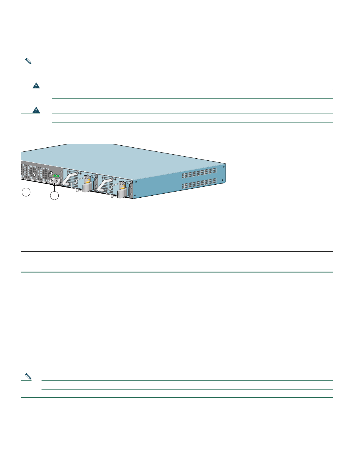
Install the AC Power Supply
This section provides information about installing an AC power supply in the Cisco 7201 router.
Note At first customer ship, the power supply may or may not have a handle; later power supplies will have a handle.
Warning
Warning
Never install an AC power module and a DC power module in the same chassis.
Installation of the equipment must comply with local and national electrical codes.
Figure 38 Installing the AC Power Supply
L
Y
C
O
N
N
E
C
T
IO
N
. A
L
L
C
O
N
N
E
C
T
I
O
N
S
M
U
S
T
B
E
R
E
M
O
V
E
D
T
O
D
E
-
E
N
E
R
G
I
Z
E
T
H
E
U
N
I
T
PWR
SLOT 1 OK
PWR
SLOT 2 OK
PWR
SLOT 1
1
Power up restrictor
1
Upper power supply captive installation screw
2
2
Statement 1050
.
Statement 1074
PWR
SLOT 2
Lower power supply captive installation screw
3
170934
Step 1 Insert an AC power supply in power supply slot 1 or power supply slot 2 until it is fully seated.
Step 2 Tighten the captive installation screws.
a. Tighten the lower power supply captive installation screw.
b. Push the power up restrictor to the left to allow you to tighten the upper power supply captive installation screw. Tighten
the upper power supply captive installation screw.
c. Release the power up restrictor so that it again covers the upper power supply captive installation screw.
Step 3 Slide the wire cable-retention clip to the left.
Step 4 Insert the AC power cable.
Step 5 Slide the wire cable-retention clip to the right, over the power supply cable.
Step 6 Plug the power supply cable into the power source.
Step 7 On the front of the router, place the power switch in on (O) the router to turn on the router.
Note After powering off the router, wait a minimum of 30 seconds before powering it on again.
48
Page 49

Remove the DC Power Supply
Because of the power supply redundancy, there is no need to power off the Cisco 7201 router before removing one of the DC
power supplies.
Warning
Before performing any of the following procedures, ensure that power is removed from the DC circuit.
Statement 1003
Warning
Only trained and qualified personnel should be allowed to install, replace, or service this equipment.
Statement 1030
Warning
Installation of the equipment must comply with local and national electrical codes.
Figure 39 Removing the Ground Lugs
Statement 1074
A
B
PWR
SLOT 2
170970
Caution The DC return connection to this system is to remain isolated from the system frame and chassis (DC-I).
Step 1 Switch the circuit breaker to the off position, and tape the switch handle to the off position.
Step 2 Pull the terminal block plug from the terminal block.
Step 3 Locate the DC power supply grounding stud.
Step 4 Remove the nut, ground lug, star washer, ground lug, and star washer and save for reuse on the new DC power supply.
Step 5 Move the power up restrictor to the left to gain access to the upper power supply captive installation screw.
Step 6 Use a Number 2 Phillips screwdriver to unscrew the upper power supply captive installation screw.
Step 7 Unscrew the lower power supply captive installation screw on the lower left of the power supply.
Step 8 Grasping the captive installation screws, pull the power supply from the chassis.
49
Page 50
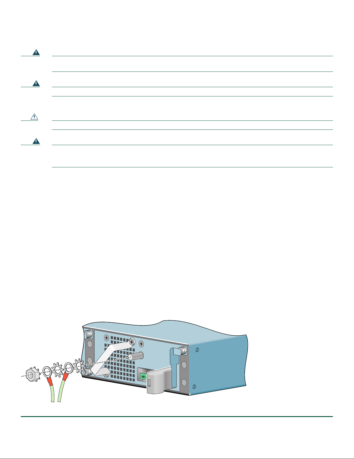
Install the DC Power Supply
Warning
Warning
This product relies on the building’s installation for short-circuit (overcurrent) protection. Ensure that the
protective device is rated not greater than: 120 VAC, 20A U.S. (240 VAC, 10A international).
Never install an AC power module and a DC power module in the same chassis.
Statement 1050
Statement 1005
This section provides instructions for installing the DC power supply ground leads and installing the DC-input power leads.
Caution Before you connect DC-input power, you must install the DC power ground leads to the DC power supply.
Warning
This equipment must be grounded. Never defeat the ground conductor or operate the equipment in the absence of
a suitably installed ground conductor. Contact the appropriate electrical inspection authority or an electrician if
you are uncertain that suitable grounding is available.
Statement 1024
Obtain these necessary tools and equipment:
• Ratcheting torque screwdriver with a Phillips head that exerts up to 15 pound force-inches (lbf in.) or 240 ounce
force-inches (ozf in.) of pressure
• Panduit crimping tool with optional controlled cycle mechanism
• 18-gauge copper ground wire (insulated or noninsulated)
• Four leads of 18-gauge copper wire
• Wire-stripping tool for stripping 18-gauge wire
Install the DC Grounding Leads
To install the DC grounding leads on the DC power supply, follow these instructions.
The DC power supply ships with the DC power supply ground lugs, star washers, and nut attached to the grounding stud on
the DC power supply.
• If you are going to use the new ground lug and attach it to new ground wire, see the “Install the DC Grounding Leads”
section on page 23.
• If you are going to use the current ground lug and ground wire with the new DC power supply, follow the instructions below.
Figure 40 Locating the DC Grounding Stud and Grounding Materials
A
B
PWR
SLOT 2
170970
Step 1 Locate the grounding stud on the DC power supply.
50
Page 51

Step 2 Using the ground lugs from the previous power supply, replace them and the star washers and nut in the following order.
If you are using the new lugs that came with the new DC power supply, see the “Install the DC Grounding Leads”
section on page 23 for instructions on wiring the ground lugs and ground wires.
Place the ground lugs, star washers, and nut on the grounding stud in this order:
a. Star washer
b. Ground lug with ground wire
c. Star washer
d. Ground lug with ground wire
e. Nut
Step 3 Tighten the nut to complete the installation.
Wire the DC-Input Power Source
Note The color coding of the DC-input power supply leads depends on the color coding of the DC power source at your site.
Make certain the lead color coding you choose for the DC-input power supply matches lead color coding used at the
DC power source.
Warning
Warning
Warning
Warning
Step 1 Check to make sure the power supply LEDs are off and the Cisco 7201 power switch is in the standby (|) position.
Step 2 If you have not already done so when removing the ground lugs, move the circuit-breaker switch handle to the
When installing or replacing the unit, the ground connection must always be made first and disconnected last.
Statement 1046
This product relies on the building’s installation for short-circuit (overcurrent) protection. Ensure that the
protective device is rated not greater than: 120 VAC, 20A U.S. (240 VAC, 10A international).
Before performing any of the following procedures, ensure that power is removed from the DC circuit.
Statement 1003
Only trained and qualified personnel should be allowed to install, replace, or service this equipment.
Statement 1030
off position, and apply tape to hold it in the off position.
Statement 1005
51
Page 52
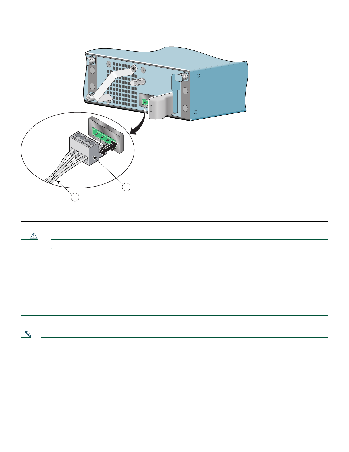
Figure 41 Inserting the Terminal Block Plug in the Block Header
B
A
A
B
2
1
PWR
SLOT 2
170973
1
Tie wrap
Terminal block plug
2
Caution Secure the wires coming in from the terminal block plug so that they cannot be disturbed by casual contact.
Step 3 Use a tie wrap to secure the wires to the rack, so that the wires are not pulled from the terminal block plug by casual
contact.
Step 4 Insert the terminal block plug in the terminal block header on the DC power supply panel, as shown in Figure 41.
Step 5 Repeat Step 1 through Step 4 if you are replacing a second DC power supply.
Step 6 Remove the tape from the circuit-breaker switch handle, and move the circuit-breaker switch handle to the on position.
Step 7 Turn the router power switch to the on (O) position.
Step 8 Switch the circuit breaker to the on position.
Note After powering off the router, wait a minimum of 30 seconds before powering it on again.
52
Page 53

Replace the Port Adapter or Service Adapter
The port adapter or service adapter ships installed. These instructions are provided for future use. Cabling information is
included with the specific port adapter documentation.
Figure 42 Removing and Installing the Port Adapter
3
G
IG
A
B
S
IT
L
O
E
T
T
1
H
E
R
N
E
T
0
/0
R
J4
5
E
N
G
IG
A
B
I
T
E
L
IN
T
H
K
E
R
N
E
T
R
S
IE
L
M
R
L
R
R
E
A
A
L
C
C
X
ENABLED
A
X
R
X
R
R
ATM
1
2
0/1
R
J4
5
TX
E
N
G
B
IC
G
IG
R
AB
X
IT
L
IN
E
K
Cisco 7201
R
J
4
5
E
N
C
IS
C
O
730
G
E
1
T
HE
RN
E
T
0
/
2
R
J4
T
X
5
G
E
B
N
IC
R
X
L
IN
A
U
K
L
I
N
K
/
A
C
T
V
S
F
P
R
J
4
0
/
0
X
C
O
N
C
S
O
O
N
L
S
E
O
T
L
X
E
G
B
IC
R
X
5
E
N
L
IN
K
/
A
C
T
V
L
IN
K
/
T
A
X
C
S
T
F
V
P
R
X
L
IN
S
K
F
/
A
P
C
T
V
T
X
S
F
P
R
X
M
G
E
0
/1
G
E
0
/2
G
E
0
/3
A
U
X
1
0
0
-2
4
0
V
,
2
A
,
5
0/
6
0
H
24
z
V
=
9
A
, 4
8
-
6
0
V
=
A
5
L
A
A
R
M
N
G
M
N
T
U
C
S
O
E
M
O
P
A
N
C
L
T
Y
FL
A
S
H
S
T
A
T
U
S
A
L
A
R
M
P
W
R
O
F
E
0
/0
L
K
0
F
E
I
N
K
S
T
A
T
U
S
COMPACT FLASH
C
F
A
C
T
V
170872
Port adapter lever
1
Port adapter
2
Warning
During these procedures, wear grounding wrist straps to avoid ESD damage to the card. Do not directly touch the
backplane with your hand or any metal tool, or you could shock yourself.
Port adapter slot guide
3
Statement 94
Before removing any port adapter, gracefully shut down the interface so that there is no traffic running through the port adapter
when it is removed. Removing a port adapter while traffic is flowing through the ports can cause system disruption.
Step 1 Attach an ESD-preventative wrist strap between you and an unpainted chassis surface.
Step 2 Disconnect all cables from the port adapter.
Step 3 Remove the port adapter from the chassis slot by sliding the port adapter lever to the unlocked position.
Step 4 Grasp the handle and pull the port adapter or port adapter blank panel from the router.
Step 5 Locate the port adapter slot guides inside the Cisco 7201 router. They are near the top, and are recessed about one-half
inch.
Caution The port adapter must slide into the slot guides under the chassis lid. Do not allow the port adapter components to come
in contact with the system board or the port adapter could be damaged.
Step 6 Carefully slide the port adapter into the port adapter slot and seat it. When installed, the port adapter input/output
panel should be flush with the face of the router.
Step 7 Move the port adapter lever to the locked position.
Step 8 Reconnect any cables, including the port adapter and power cables, and place the cables through any cable-management
bracket or power cable-retention clip.
Step 9 Power on the router by turning the power switch to the on (O) position.
53
Page 54

Note If the port adapter fails to come up, reseat or reinsert the port adapter: do not use excessive force.
Replace the DIMM
This section provides information about replacing the DIMM.
Power Off the Router and Remove the Cover
This section provides information for powering off the router and removing the cover.
Warning
During these procedures, wear grounding wrist straps to avoid ESD damage to the card. Do not directly touch the
backplane with your hand or any metal tool, or you could shock yourself.
Statement 94
Warning
This unit might have more than one power supply connection. All connections must be removed to de-energize the
unit.
Statement 1028
Step 1 Attach an ESD-preventative wrist or ankle strap, connecting the equipment end of the strap to an unfinished chassis
surface.
Step 2 Power off the router by turning the power switch to the standby (|) position.
Note After powering off the router, wait a minimum of 30 seconds before powering it on again.
Step 3 Remove any power and input/output cables from the Cisco 7201 router. For AC power supplies, unplug the AC power
cord from the power outlet. For DC power supplies, to ensure that all power is off, locate the circuit breaker on the
panel board that services the DC circuit, switch the circuit breaker to the off position, tape the switch handle of the
circuit breaker in the off position, and remove the DC connector.
Step 4 Remove the ground cable.
Step 5 Remove the Cisco 7201 router from the rack, if it is rack-mounted.
Figure 43 Removing the Cover
T
H
IS
U
N
IT
M
A
Y
H
A
V
E
M
O
R
E
T
H
A
N
O
N
E
P
O
W
E
R
S
U
P
P
L
Y
C
O
N
N
E
C
T
IO
N
. A
L
L
C
O
N
N
E
C
T
IO
N
1 Cover screws
54
1
S
M
U
S
T
B
E
R
E
M
O
V
E
D
T
O
D
E
E
N
E
R
G
IZ
E
T
H
E
U
N
IT
PWR
SLOT 1 OK
PWR
SLOT 2 OK
PWR
SLOT 1
PWR
SLOT 2
170954
Page 55
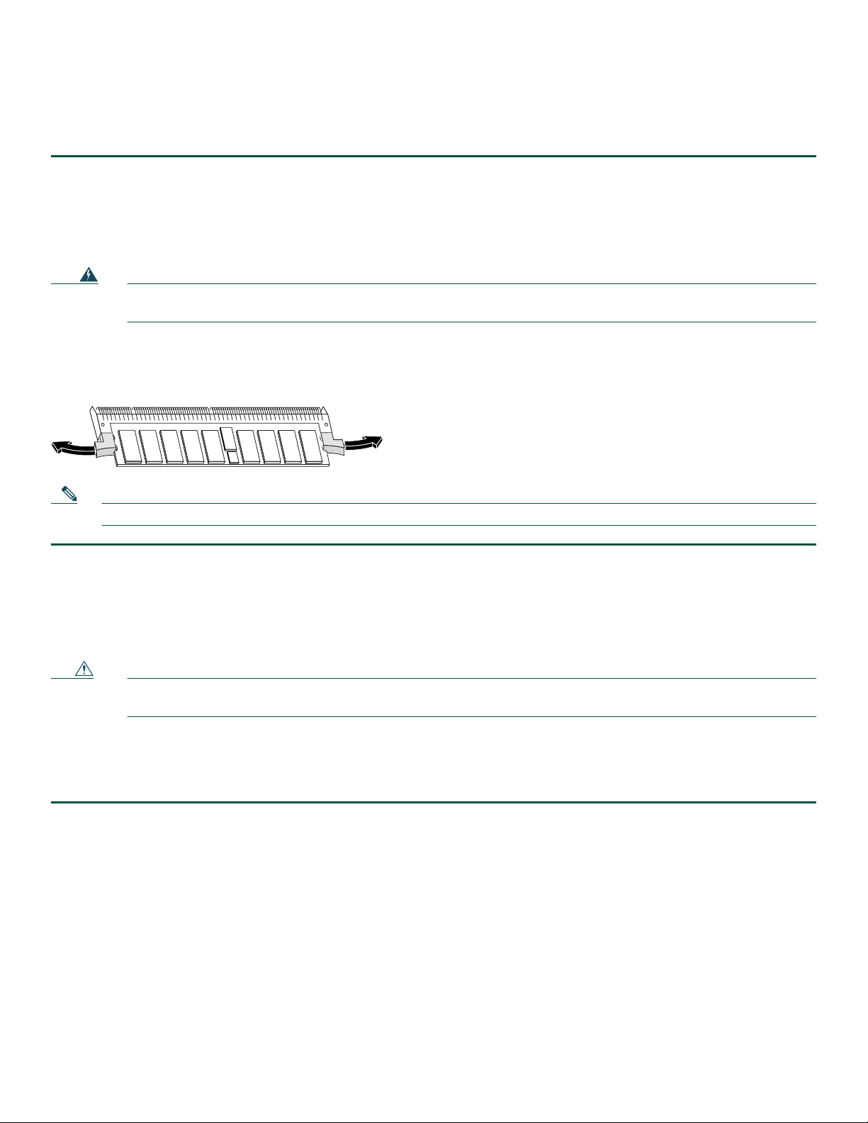
Step 6 Turn the Cisco 7201 so that the back is facing you.
Step 7 Using a Phillips screwdriver, loosen the fifteen cover screws holding the cover to the chassis.
Step 8 Lift the cover off the router.
Remove and Install the DIMM
The information in this section provides instructions for replacing the DDR-SDRAM DIMM. The memory configuration you
ordered is installed in the Cisco 7201 router.
Warning
During these procedures, wear grounding wrist straps to avoid ESD damage to the card. Do not directly touch the
backplane with your hand or any metal tool, or you could shock yourself.
Statement 94
To replace or upgrade the DIMM, follow these instructions:
Figure 44 Removing and Replacing the DIMM
170953
Note Use only a DIMM purchased from Cisco.
Step 1 Attach an ESD-preventative wrist strap between you and an unpainted router surface.
Step 2 Locate the DIMM on the system board.
Step 3 Press both spring latches outward to release the DIMM.
Step 4 Gently pull the DIMM free from the DIMM socket, taking care not to touch the pins that insert into the socket. Place
the DIMM in an anti-static bag.
Caution Forcing the DIMM into the socket can damage the DIMM. Use the notches on the DIMM to align the DIMM in
the DIMM socket before inserting it.
Step 5 Locate the notches and align the DIMM with the socket before inserting it.
Step 6 Gently insert the new DIMM, taking care not to damage the pins on the edge of the DIMM.
Step 7 Press down on the DIMM until the spring latches lock the DIMM in place.
For memory specifications and configurations, see Appendix A, “Specifications,” of the online Cisco 7201 Installation and
Configuration Guide.
55
Page 56
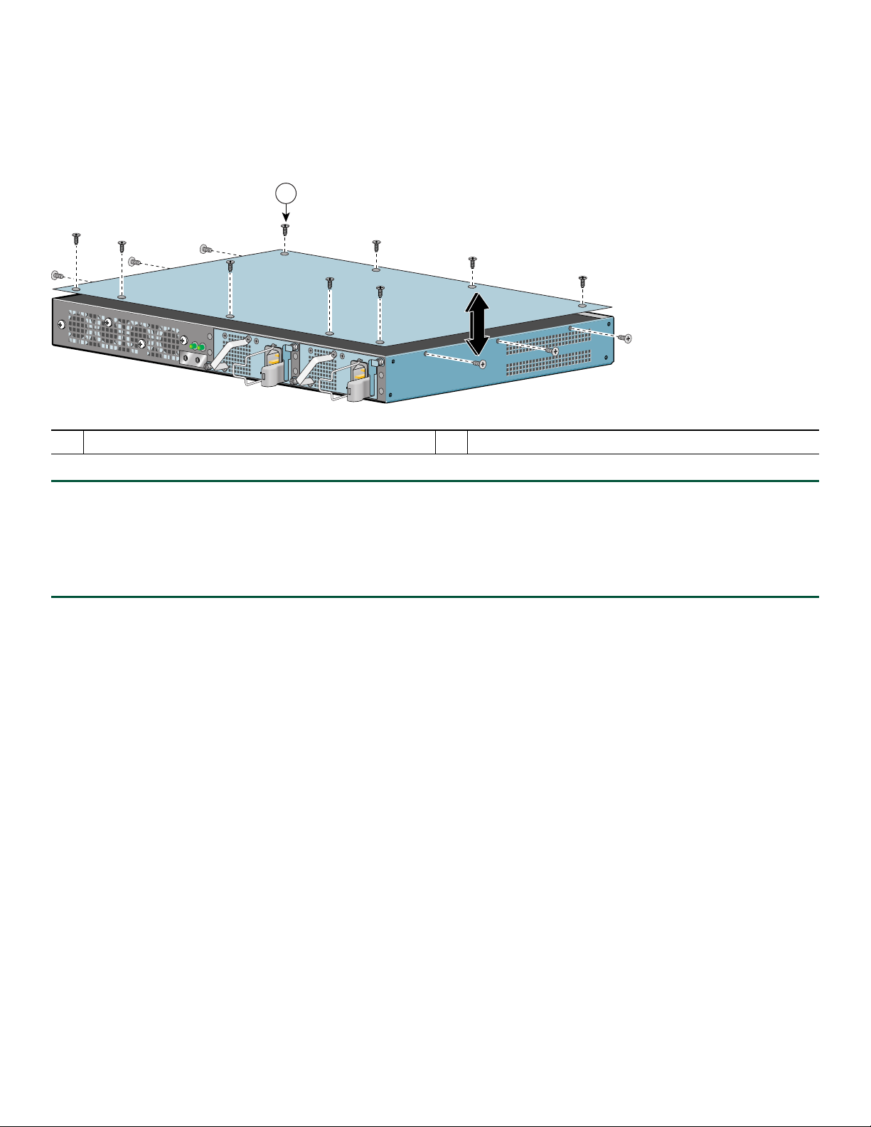
Replace the Cover and Power On the Router
Follow these instructions to replace the cover and power on the router:
Figure 45 Inserting the Screws and Replacing the Cover
1
T
H
IS
U
N
I
T
M
A
Y
H
A
V
E
M
O
R
E
T
H
A
N
O
N
E
P
O
W
E
R
S
U
P
P
L
Y
C
O
N
N
E
C
T
IO
N
.
A
L
L
C
O
N
N
E
C
T
IO
N
S
M
U
S
T
B
E
R
E
M
O
V
E
D
T
O
D
E
-E
N
E
R
G
I
Z
E
T
H
E
U
N
IT
PWR
SLOT 1 OK
PWR
SLOT 2 OK
PWR
SLOT 1
PWR
SLOT 2
1 Cover screws
Step 1 Place the cover on the top of the router with the four-screw edge aligned with the front of the router, and the five-screw
edge aligned with the rear of the router.
Step 2 Insert and tighten the fifteen cover screws with a Phillips screwdriver.
Step 3 Return the router to its installation site, attach the ground cable, and input/output and power cables.
Step 4 Power on the router by turning the power switch to the on position.
170954
56
Page 57

57
Page 58

Americas Headquarters
r,
,
t
o
Cisco Systems, Inc.
170 West Tasman Drive
San Jose, CA 95134-1706
USA
www.cisco.com
Tel: 408 526-4000
800 553-NETS (6387)
Fax: 408 527-0883
Asia Pacific Headquarters
Cisco Systems, Inc.
168 Robinson Road
#28-01 Capital Tower
Singapore 068912
www.cisco.com
Tel: +65 6317 7777
Fax: +65 6317 7799
Europe Headquarters
Cisco Systems International BV
Haarlerbergpark
Haarlerbergweg 13-19
1101 CH Amsterdam
The Netherlands
www-europe.cisco.com
Tel: 31 0 800 020 0791
Fax: 31 0 20 357 1100
Cisco has more than 200 offices worldwide. Addresses, phone numbers, and fax numbers are listed on the
Cisco Website at www.cisco.com/go/offices.
CCVP, the Cisco logo, and Welcome to the Human Network are trademarks of Cisco Systems, Inc.; Changing the Way We Work, Live, Play, and Learn is a service mark of Cisco Systems, Inc.; and Access Registra
Aironet, Catalyst, CCDA, CCDP, CCIE, CCIP, CCNA, CCNP, CCSP, Cisco, the Cisco Certified Internetwork Expert logo, Cisco IOS, Cisco Press, Cisco Systems, Cisco Systems Capital, the Cisco Systems logo
Cisco Unity, Enterprise/Solver, EtherChannel, EtherFast, EtherSwitch, Fast Step, Follow Me Browsing, FormShare, GigaDrive, HomeLink, Internet Quotient, IOS, iPhone, IP/TV, iQ Expertise, the iQ logo, iQ Ne
Readiness Scorecard, iQuick Study, LightStream, Linksys, MeetingPlace, MGX, Networkers, Networking Academy, Network Registrar, PIX, ProConnect, ScriptShare, SMARTnet, StackWise, The Fastest Way t
Increase Your Internet Quotient, and TransPath are registered trademarks of Cisco Systems, Inc. and/or its affiliates in the United States and certain other countries.
All other trademarks mentioned in this document or Website are the property of their respective owners. The use of the word partner does not imply a partnership relationship between Cisco and any other company.
(0711R)
© 2008 Cisco Systems, Inc. All rights reserved.
Printed in the USA on recycled paper containing 10% postconsumer waste.
OL-11363-02
 Loading...