

Page 1

Cisco 7201 Installation and Configuration Guide
Americas Headquarters
Cisco Systems, Inc.
170 West Tasman Drive
San Jose, CA 95134-1706
USA
http://www.cisco.com
Tel: 408 526-4000
800 553-NETS (6387)
Fax: 408 527-0883
Customer Order Number:
Text Part Number: OL-11364-04
Page 2

THE SPECIFICATIONS AND INFORMATION REGA RDING THE P RODUCTS IN THIS MANUAL ARE SUBJECT TO CHANGE W ITH OUT NOT ICE. A LL
STATEMENTS, INFORMATION, AND RECOMMENDATIONS IN THIS MANUAL ARE BELIEVED TO BE ACCURATE BUT ARE PRESENTED WITHOUT
WARRANTY OF ANY KIND, EXPRESS OR IMPLIED. USERS MUST TAKE FULL RESPONSIBILIT Y FOR THEIR APPLICATION OF ANY PRODUCTS.
THE SOFTWARE LICENSE AND LIMITED WARRA NTY FO R THE A CCOMPA NYING PRODUCT A RE SET FORTH IN T HE INFORM ATION P ACKET THAT
SHIPPED WITH THE PRODUCT AND ARE INCORPORATED HEREIN BY THIS REFERENCE. IF YOU ARE UNABLE TO LOCATE THE SOFTWARE LICENSE
OR LIMITED WARRANTY, CONTACT YOUR CISCO REPRESENTATIVE FOR A COPY.
The following information is for FCC compliance of Class A devices: This equipment has been tested and found to comply with the limits for a Class A di gital device, pursuant
to part 15 of the FCC rules. These limits are designed to provide reasonable protection against harmful interference when the equipment is operated in a commercial
environment. This equipment generates, uses, and can radiate radio-frequency energy and, if not installed and used in accordance with the instruction manual, may cause
harmful interference to radio communications. Operation of this equipment in a residential area is likely to cause harmful interference, in which case users will be required
to correct the interference at their own expense.
The following information is for FCC compliance of Class B devices: The equipment described in this manual generates and may radiate radio-frequency energy. If it is not
installed in accordance with Cisco’s installation instructions, it may cause interference with radio and television reception. This equipment has been tested and found to
comply with the limits for a Class B digital device in accordance with the specifications in part 15 of the FCC rules. These specifications are designed to provide reasonable
protection against such interference in a residential installation. However, there is no guarantee that interference will not occur in a particular installation.
Modifying the equipment without Cisco’s written authorization may result in the equipment no longer complying with FCC requirements for Class A or Class B digital
devices. In that event, your right to use the equipment may be limited by FCC regulations, and you may be required to correct any interference to radio or television
communications at your own expense.
You can determine whether your equipment is causing interference by turning it off. If the interference stops, it was pr obabl y caused by the Cisco equipment or one of its
peripheral devices. If the equipment causes interference to radio or television reception, try to correct the interference by using one or more of the following measures:
• Turn the television or radio antenna until the interference stops.
• Move the equipment to one side or the other of the television or radio.
• Move the equipment farther away from the television or radio.
• Plug the equipment into an outlet that is on a different circuit from the television or radio. (That is, make certain the equipment and the television or radio are on circuits
controlled by different circuit breakers or fuses.)
Modifications to this product not authorized by Ci sco Systems, Inc. could void the FCC approval and negate your auth ority to op erate the product.
The Cisco implementation of TCP header compression is an adaptation of a program developed by the University of California, Berkeley (UCB) as part of UCB’s public
domain version of the UNIX operating system. All rights reserved. Copyright © 1981, Regents of the University of California.
NOTWITHSTANDING ANY OTHER WARRANTY HEREIN, ALL DO CUMENT FILES AND SOFTW ARE OF THESE SUPPL IERS ARE PROVIDED “AS IS” WITH
ALL FAULTS. CISCO AND THE ABOVE-NAMED SUPPLIERS DISCLAIM AL L WARRANTIES, EX PRESSED OR
LIMITATION, THOSE OF MERCHANTABILITY, FITNESS FOR A PARTICUL AR PURPOSE AND NON INFRINGEMENT OR ARISIN G FROM A COURSE OF
DEALING, USAGE, OR TRADE PRACTICE.
IN NO EVENT SHALL CISCO OR ITS SUPPLIERS BE LIABLE FOR ANY INDIRECT, SPECIAL, CONSEQUENTIAL, OR INCIDENTAL DAMAGES, INCLUDING,
WITHOUT LIMITATION, LOS T PROFITS OR LOSS OR DAMAGE TO DATA ARISIN G OUT OF THE US E OR INABILI TY TO USE THIS MA NUAL, EVEN I F CISCO
OR ITS SUPPLIERS HAVE BEEN ADVISED OF THE POSSIBILITY OF SU CH DAMA GES.
CCDE, CCENT, Cisco Eos, Cisco Lumin, Cisco Nexus, Cisco StadiumVision, Cisco TelePresence, Cisco WebEx, the Cisco logo, DCE, and Welcome to the Human Network
are trademarks; Changing the Way We Work, Live, Play, and Learn and Cisco Store are service marks; and Access Registrar, Aironet, AsyncOS, Bringing the Meeting To
You, Catalyst, CCDA, CCDP, CCIE, CCIP, CCNA, CCNP, CCSP, CCVP, Cisco, the Cisco
Cisco
Systems Capital, the Cisco Systems logo, Cisco Unity, Collaboration Without Limitation, EtherFast, EtherSwitch, Event Center, Fast Step, Follow Me Browsing,
FormShare, GigaDrive, HomeLink, Internet Quotient, IOS, iPhone, iQuick Study, IronPort, the IronPort
MeetingPlace Chime Sound, MGX, Networkers, Networking Academy, Network Registrar, PCNow, PIX, PowerPanels, ProConnect, ScriptShare, SenderBase, SMARTnet,
Spectrum Expert, StackWise, The Fastest Way to Increase Your Internet Quotient, TransPath, WebEx, and the WebEx
and/or its affiliates in the United States and certain other countries.
All other trademarks mentioned in this document or website are the property of their respective owners. The use of the word partner does not impl y a partner ship relati onshi p
between Cisco and any other company. (0809R)
Any Internet Protocol (IP) addresses us ed in this docu ment ar e not i ntend ed to be ac tual address es. A ny ex amples, comma nd d ispl ay outp ut, and figu res included in the
document are shown for illustrative purposes only. Any use of actual IP addresses in illustrative content is unintentional and coincidental.
Cisco 7201 Installation and Configuration Guide
© 2008 Cisco Systems, Inc. All rights reserved.
Certified Internetwork Expert logo, Cisco IO S, Cisco Press, Cisco Systems,
logo, LightStream, Linksys, MediaTone, MeetingPlace,
IMPLIED, INCLUDING, WITHOUT
logo are registered trademarks of Cisco Systems, Inc.
Page 3

CONTENTS
Preface ix
Document Revision History i-ix
Document Objectives i-ix
Audience i-x
Document Organization i-x
Safety Warnings and Cautions i-x
Warning Definition i-xi
Lithium Battery Caution i-xvi
Related Documentation i-xvii
Obtaining Documentation, Obtaining Support, and Security Guidelines i-xviii
CHAPTER
CHAPTER
1 Cisco 7201 Features 1-2
Cisco 7201 Hardware Overview 1-3
Front View 1-3
Faceplate LEDs 1-4
SFP Module Information 1-5
USB Port Information 1-6
CompactFlash Disk Information 1-7
Rear View 1-7
Power Supply LEDs 1-8
Interior View 1-9
System Board 1-9
System Management Functions 1-10
Checking the Shipping Container Contents 1-11
Cisco 7201 Router Installation Checklist 1-11
2 Preparing to Install the Cisco 7201 Router 2-1
Site Preparation and Unpacking 2-2
Tools and Parts Required 2-3
Electrical Equipment Guidelines 2-4
Preventing Electrostatic Discharge Damage 2-4
Site Requirement Guidelines 2-4
OL-11364-04
Installing the Router 2-5
General Tabletop or Workbench Installation 2-5
Cisco 7201 Installation and Configuration Guide
iii
Page 4

Contents
Rack-Mounting a Cisco 7201 Router 2-6
Attaching the Chassis Rack-Mount and Cable-Management Brackets 2-7
Installing Rack-Mount Brackets on the Front of the Chassis 2-7
Attaching the Cable-Management Bracket 2-8
Installing Rack-Mount Brackets on the Rear of the Chassis 2-8
Installing the Chassis in the Rack 2-9
Two-Post Rack Installation 2-10
Four-Post Rack Installation 2-11
Attaching a Chassis Ground Connection 2-12
Installing a Port Adapter, USB Flash Memory Module, or SFP Module That Did Not Ship in the
System 2-14
Connecting Port Adapter Cables 2-14
Connecting I/O Cables 2-14
Connecting Console and Auxiliary Port Cables 2-15
Connecting the Fast Ethernet Management Port Cable 2-17
Connecting Native Gigabit Ethernet Cables 2-18
Gigabit Ethernet SFP Connection Equipment 2-18
Installing the SFP Module Optical Fiber Cables 2-19
Mode-Conditioning Patch Cord Description 2-21
Attaching the Mode-Conditioning Patch Cord 2-22
Attaching the Gigabit Ethernet RJ-45 Cables 2-22
CHAPTER
Using the Cable-Management Bracket 2-23
Connecting Power 2-24
Connecting AC-Input Power 2-24
Connecting DC-Input Power 2-26
Installing the DC Grounding Leads 2-27
Wiring the DC-Input Power Source 2-29
3 Functional Overview 3-1
Chassis Slot and Logical Interface Numbering 3-2
MAC Address 3-3
Online Insertion and Removal 3-4
Environmental Monitoring and Reporting Functions 3-4
Environmental Monitoring 3-5
Reporting Functions 3-6
Fan Failures 3-8
Checking Conditions Prior to System Startup 3-8
Starting the System and Observing Initial Conditions 3-8
iv
Cisco 7201 Installation and Configuration Guide
OL-11364-04
Page 5

Configuring a Cisco 7201 Router 3-9
Performing a Basic Configuration Using AutoInstall 3-10
Performing a Basic Configuration Using the Setup Facility 3-10
Configuring Global Parameters 3-11
Configuring the Native Gigabit Ethernet Interfaces 3-15
Configuring Port Adapter Interfaces 3-17
Performing a Basic Configuration Using Global Configuration Mode 3-20
Checking the Running Configuration Settings 3-21
Saving the Running Configuration to NVRAM 3-21
Performing Other Configuration Tasks 3-22
Upgrading ROMmon on the Cisco 7201 3-22
Using the show rom-monitor Command and showmon Command 3-23
Using the upgrade rom-monitor Command 3-23
Changing Preferences to Change the ROMmon Image 3-24
Contents
CHAPTER
Troubleshooting the Upgrade 3-24
ROMmon Upgrade Error Messages 3-24
Upgrading FPGA 3-25
Replacing or Recovering a Lost Password 3-26
Overview of the Password Recovery Procedure 3-26
Details of the Password Recovery Procedur e 3-27
Viewing Your System Configuration 3-29
Performing Complex Configurations 3-30
4 Removing and Installing an SFP Module 4-2
Removing an SFP Module 4-2
Installing an SFP Module 4-2
Removing and Installing the CompactFlash Disk 4-3
Removing and Installing a USB Flash Memory Module or
USB eToken Pro Key 4-4
Removing and Installing a Port Adapter or Service Adapter 4-5
Removing and Installing an AC Power Supply 4-7
Removing the AC Power Supply 4-7
Installing the AC Power Supply 4-9
OL-11364-04
Removing and Installing a DC Power Supply 4-10
Removing the DC Power Supply 4-10
Installing the DC Power Supply 4-11
Installing the DC Grounding Leads 4-12
Wiring the DC-Input Power Source 4-13
Cisco 7201 Installation and Configuration Guide
v
Page 6

Contents
Removing and Installing a DIMM 4-15
Powering Off the Router and Removing the Cover 4-15
Removing and Installing the DIMM 4-16
Replacing the Cover and Powering On the Router 4-18
CHAPTER
APPENDIX
5 Troubleshooting Overview 5-1
Online Troubleshooting Resources 5-2
Problem Solving Using a Subsystems Approach 5-3
Identifying Startup Problems 5-3
Troubleshooting the Power Subsystem 5-4
Troubleshooting the Cooling Subsystem 5-6
Troubleshooting the I/O Subsystem 5-7
Troubleshooting the Processor Subsystem 5-7
Troubleshooting the Port Adapter or Service Adapter 5-8
Upgrading the Boot Helper (Boot Loader) Image 5-8
Boot Prompt: (boot)# 5-9
ROMmon Prompt: rommon > 5-10
Complete Boot Prompt and ROMmon Prompt Example 5-11
Cleaning the Fiber-Optic Connections 5-14
A Specifications A-1
Cisco 7201 Router Specifications A-1
Power Supply Product Numbers A-2
APPENDIX
vi
Software Requirements A-3
Processor and Memory Specifications A-3
SFP Module Specifications and Configurations A-4
Gigabit Ethernet RJ-45 Port Pinouts A-6
Gigabit Ethernet Flow Control Information A-9
Console Port and Auxiliary Port Signals and Pinouts A-10
B Using the CompactFlash Disk B-1
Product Description B-1
Hardware and Software Requirements B-2
Tools and Parts Required B-2
Compatibility Requirements B-2
System Memory and Software Image Functions and Interactions B-3
Boot Environment Variables B-3
Cisco 7201 Installation and Configuration Guide
OL-11364-04
Page 7

Sample Upgrade Process B-5
Working with a CompactFlash Disk B-5
Software Command Overview B-6
Using Software Commands B-7
Using the cd Command B-8
Using the show Command B-8
Using the pwd Command B-9
Using the dir Command B-9
Using the format Command B-9
Using the mkdir Command B-10
Using the rmdir Command B-11
Using the delete Command B-11
Enabling Booting from a CompactFlash Disk B-12
Making a CompactFlash Disk-Based Software Image the Bootable
Software Image B-13
Contents
APPENDIX
I
NDEX
C Configuration Register Information C-1
Configuration Bit Meanings C-1
Bits 0–3 C-2
Bit 6 C-3
Bit 7 C-3
Bit 8 C-4
Bit 10 and Bit 14 C-4
Bit 11 and Bit 12 C-4
Bit 13 C-4
Bit 15 C-5
Displaying the Configuration Register While Running Cisco IOS C-5
Displaying the Configuration Register While Running ROM Monitor C-5
Setting the Configuration Register While Running Cisco IOS C-6
Setting the Configuration Register While Running ROM Monitor C-6
OL-11364-04
Cisco 7201 Installation and Configuration Guide
vii
Page 8

Contents
viii
Cisco 7201 Installation and Configuration Guide
OL-11364-04
Page 9

Preface
This preface discusses the objectives, audience, and organization of this publication. The following
sections are in this preface:
• Document Revision History, page ix
• Document Objectives, page ix
• Audience, page x
• Document Organization, page x
• Safety Warnings and Cautions, page x
• Related Documentation, page xvii
• Obtaining Documentation, Obtaining Support, and Security Guidelines, page xviii
Document Revision History
The Document Revision History table below records technical changes to this document.
Document
Version
OL-11364-04 Novemb er, 2 00 8 Revised rack-mount bracket installation instructions.
OL-11364-03 August, 2008 Added information about SFP-GE-F module.
OL-11364-02 June, 2007 Added additional software support information.
OL-11364-01 April, 2007 This is the first version of this document.
Document Objectives
This publication describes the installation and configuration of the Cisco 7201 router, replacement or
upgrading of field replaceable units (FRUs), and troubleshooting of the Cisco 7201 hardware. The
purpose of this guide is to enable the safe and efficient installation of the Cisco 7201 router.
OL-11364-04
Date Change Summary
Cisco 7201 Installation and Configuration Guide
ix
Page 10

Preface
Audience
Audience
This publication is primarily designed for the person responsible for installing, maintaining, and
troubleshooting the Cisco 7201 router. The users of this guide should be familiar with electronic
circuitry and wiring practices and have experience as electronic or electromechanical technicians. Users
of this guide should also have experience in installing high-end networking equipment. Certain
procedures described in this guide require a certified electrician.
For configuration applications, refer to the Ci sco IOS configuration guides and com mand references and
to the documents listed in the
“Related Documentation” section on page xvii.
Document Organization
The major sections of this installation and configuration guide are as follows:
Chapter and Appendix Number and Title Description
Chapter 1, “Overview” This chapter provides an overview of the Cisco 7201.
Chapter 2, “Installing the Cisco 7201 Router” This chapter provides preparation and installation
instructions for installing the chassis in a rack and for
attaching cables.
Chapter 3, “Starting and Configuring the Rout er” This chapter provides a functional overview of the
system as well as startup and configuration instructions.
Chapter 4, “Replacing Cisco 7201 Field-Replaceable Units” This chapter provides instructions for removing and
replacing power supplies, SDRAM, CompactFlash
disks, USB memory, SFP modules, and port adapters
and service adapters.
Chapter 5, “Troubleshooting Initial Startup Problems” This chapter provides basic system startup
troubleshooting information.
Appendix A, “Specifications” This appendix provides system specifications as well as
port and cabling pinouts and specifications.
Appendix B, “Using the CompactFlash Disk” This appendix provides instructions for using the
CompactFlash Disk.
Appendix C, “Configuration Register Information” This appendix provides configuration register
information.
Safety Warnings and Cautions
Most safety warnings for the Cisco 7201 router are placed in rele v ant sections througho ut the document.
For translated safety warnings, see the
Series Routers. Below is Statement 1071, the Warning Definition statement, complete with translated
warnings.
Translated warning statement numbers are listed at the end of each warning. They correspond to the
translated safety warning statement numbers found in translated warning statement headings in the
Regulatory Compliance and Safety Information for Cisco 7200 Series Routers document.
Cisco 7201 Installation and Configuration Guide
x
Regulatory Compliance and Safety Information for Cisco 7200
OL-11364-04
Page 11

Preface
Warning Definition
Safety Warnings and Cautions
Warning
Waarschuwing
Varoitus
IMPORTANT SAFETY INSTRUCTIONS
This warning symbol means danger. You are in a situ ation that could cau se bodily inju ry. Before you
work on any equipment, be aware of the hazards involved with electrical circuitry and be familiar
with standard practices for preventing accidents. Use the statement number provided at the end of
each warning to locate its translation in the translated safety warnings that accompanied this
device.
SAVE THESE INSTRUCTIONS
BELANGRIJKE VEILIGHEIDSINSTRUCTIES
Dit waarschuwingssymbool betekent gevaar. U verkeert in een situatie die lichamelijk letsel kan
veroorzaken. Voordat u aan enige apparatuur gaat werken, dient u zich bewust te zijn van de bij
elektrische schakelingen betrokken risico's en dient u op de hoogte te zijn van de standaard
praktijken om ongelukken te voorkomen. Gebruik het nummer van de verklaring onderaan de
waarschuwing als u een vertaling van de waarschuwing die bij het apparaat wordt geleverd, wilt
raadplegen.
BEWAAR DEZE INSTRUCTIES
TÄRKEITÄ TURVALLISUUSOHJEITA
Tämä varoitusmerkki merkitsee vaaraa. Tilanne voi aiheuttaa ruumiillisia vammoja. Ennen kuin
käsittelet laitteistoa, huomioi sähköpiirien käsittelemiseen liittyvät riskit ja tutustu
onnettomuuksien yleisiin ehkäisytapoihin. Turvallisuusvaroitusten käännökset löytyvät laitteen
mukana toimitettujen käännettyjen turvallisuusvaroitusten joukosta varoitusten lopussa näkyvien
lausuntonumeroiden avulla.
Statement 1071
OL-11364-04
Attention
SÄILYTÄ NÄMÄ OHJEET
IMPORTANTES INFORMATIONS DE SÉCURITÉ
Ce symbole d'avertissement indique un danger. Vous vous trouvez dans une situation pouvant
entraîner des blessures ou des dommages corporels. Avant de travailler sur un équipement, soyez
conscient des dangers liés aux circuits électriques et familiarisez-vous avec les procédures
couramment utilisées pour éviter les accidents. Pour prendre connaissance des traductions des
avertissements figurant dans les consignes de sécurité traduites qui accompagnent cet appareil,
référez-vous au numéro de l'instruction situé à la fin de chaque avertissement.
CONSERVEZ CES INFORMATIONS
Cisco 7201 Installation and Configuration Guide
xi
Page 12

Safety Warnings and Cautions
Preface
Warnung
Avvertenza
Advarsel
WICHTIGE SICHERHEITSHINWEISE
Dieses Warnsymbol bedeutet Gefahr . Sie be finden sich in einer Situation, die zu V erletzungen führen
kann. Machen Sie sich vor der Arbeit mit Geräten mit den Gefahren elektrischer Schaltungen und
den üblichen Verfahren zur Vorbeugung vor Unfällen vertraut. Suchen Sie mit der am Ende jeder
Warnung angegebenen Anweisungsnummer nach der jeweiligen Übersetzung in den übersetzten
Sicherheitshinweisen, die zusammen mit diesem Gerät ausgeliefert wurden.
BEWAHREN SIE DIESE HINWEISE GUT AUF.
IMPORTANTI ISTRUZIONI SULLA SICUREZZA
Questo simbolo di avvertenza indica un pericolo. La situazione potrebbe causare infortuni alle
persone. Prima di intervenire su qualsiasi apparecchiatura, occorre essere al corrente dei pericoli
relativi ai circuiti elettrici e conoscere le procedure standard per la prevenzione di incidenti.
Utilizzare il numero di istruzione presente alla fine di ciascuna avvertenza per individuare le
traduzioni delle avvertenze riportate in questo documento.
CONSERVARE QUESTE ISTRUZIONI
VIKTIGE SIKKERHETSINSTRUKSJONER
Dette advarselssymbolet betyr fare. Du er i en situasjon som kan føre til skade på person. Før du
begynner å arbeide med noe av utstyret, må du være oppmerksom på farene forbundet med
elektriske kretser , og kjenn e til standardprosedyrer for å forhindre u lykker. Bruk nummeret i slutten
av hver advarsel for å finne oversettelsen i de oversatte sikkerhetsadvarslene som fulgte med denne
enheten.
Aviso
¡Advertencia!
TA VARE PÅ DISSE INSTRUKSJONENE
INSTRUÇÕES IMPORTANTES DE SEGURANÇA
Este símbolo de aviso significa perigo. Você está em uma situação que poderá ser causadora de
lesões corporais. Antes de iniciar a utilização de qualquer equipamento, tenha conhecimento dos
perigos envolvidos no manuseio de circuitos elétricos e familiarize-se com as práticas habituais de
prevenção de acidentes. Utilize o número da instrução fornecido ao final de cada aviso para
localizar sua tradução nos avisos de segurança traduzidos que acompanham este dispositivo.
GUARDE ESTAS INSTRUÇÕES
INSTRUCCIONES IMPORTANTES DE SEGURIDAD
Este símbolo de aviso indica peligro. Existe riesgo para su integridad física. Antes de manipular
cualquier equipo, considere los riesgos de la corriente eléctrica y familiarícese con los
procedimientos estándar de prevención de accidentes. Al final de cada advertencia encontrará el
número que le ayudará a encontrar el texto traducido en el apartado de traducciones que acompaña
a este dispositivo.
GUARDE ESTAS INSTRUCCIONES
xii
Cisco 7201 Installation and Configuration Guide
OL-11364-04
Page 13
Preface
Safety Warnings and Cautions
Varning!
VIKTIGA SÄKERHETSANVISNINGAR
Denna varningssignal signalerar fara. Du befinner dig i en situation som kan leda till personskada.
Innan du utför arbete på någon utrustning måste du vara medveten om farorna med elkretsar och
känna till vanliga förfaranden för att förebygga olyckor. Använd det nummer som finns i slutet av
varje varning för att hitta dess översättning i de översatta säkerhetsvarningar som medföljer denna
anordning.
SPARA DESSA ANVISNINGAR
OL-11364-04
Cisco 7201 Installation and Configuration Guide
xiii
Page 14
Safety Warnings and Cautions
Preface
Aviso
Advarsel
INSTRUÇÕES IMPORTANTES DE SEGURANÇA
Este símbolo de aviso significa perigo. Você se encontra em uma situação em que há risco de lesões
corporais. Antes de trabalhar com qualquer equipamento, esteja ciente dos riscos que envolvem os
circuitos elétricos e familiarize-se com as práticas padrão de prevenção de acidentes. Use o
número da declaração fornecido ao final de cada aviso para localizar sua tradução nos avisos de
segurança traduzidos que acompanham o dispositivo.
GUARDE ESTAS INSTRUÇÕES
VIGTIGE SIKKERHEDSANVISNINGER
Dette advarselssymbol betyder fare. Du befinder dig i en situation med risiko for
legemesbeskadigelse. Før du begynder arbejde på udstyr, skal du være opmærksom på de
involverede risici, der er ved elektriske kredsløb, og du skal sætte dig ind i standardprocedurer til
undgåelse af ulykker. Brug erklæringsnummeret efter hver advarsel for at finde oversættelsen i de
oversatte advarsler, der fulgte med denne enhed.
GEM DISSE ANVISNINGER
xiv
Cisco 7201 Installation and Configuration Guide
OL-11364-04
Page 15
Preface
Safety Warnings and Cautions
OL-11364-04
Cisco 7201 Installation and Configuration Guide
xv
Page 16
Safety Warnings and Cautions
Preface
Warning
Warning
Only trained and qualified personnel should be allowed to install, replace, or service this equipment.
Statement 1030
Ultimate disposal of this product should be handled according to all national laws and regulations.
T o see translations of the warnings that appear in this publication, refer to the Regulatory Compliance
and Safety Information document that accompanied the equipment.
Lithium Battery Caution
Caution Danger of explosion if battery is incorrectly replaced.
Replace only with the same or equivalent type recommended by the manufacturer. Dispose of
used batteries according to the manufacturers instructions.
ADVARSEL!
VAROITUS
Lithiumbatteri - Eksplosionsfare ved fejlagtig håndtering. Udskiftning må kun ske med
batteri af samme fabrikat og type. Levér det brugte batteri tilbage tilleverandøren.
Paristo voi räjähtää, jos se on virheellisesti asennettu. Vaihda paristo ainoastaan
valmistajan suosittelemaan tyyppiin. Hävitä käytetty paristo valmistajan ohjeiden
mikaisesti.
Statement 1040
xvi
Cisco 7201 Installation and Configuration Guide
OL-11364-04
Page 17

Preface
Related Documentation
ADVARSEL
Eksplosjonsfare ved feilaktig skifte av batteri. Benytt samme batteri type elle r en
tilsvarende type anbefait av apparatfabrikanten. Brukte batterier kasseres i henhold til
fabrikantens instruksjoner.
VARNING
Eksplosionsfara vid felaktigt batteribyte. Använd samma batterityp eller en ekvivalent typ
som rekommenderas av apparattillverkaren. Kassera använt batteri enligt fabrikantens
instruktion.
Related Documentation
Your Cisco 7201 router and the Cisco IOS software running on it contain extensive features and
functionality, which are documented in the following resources:
• All documentation related to the Cisco 7201 router is listed in the online Cisco 7201 Router
Documentation Roadmap. Information in this master index includes troubleshooting tools and
documentation, regulatory compliance and safety information, and installation and replacement
information. Also see the Cisco 7201 Port Adapter Documentation Roadmap for specific port
adapters supported on the Cisco 7201 and the Cisco 7201 Troubleshooting Documentation
Roadmap.
Some of the Cisco 7201 documentation that is listed on the Cisco 7201 Router Documentation
Roadmap includes:
–
The Cisco 7201 Router Quick Start Guide contains installation and configuration information
and is online. It contains quick reference information about chassis or parts installation.
–
The Regulatory Compliance and Safety Information for Cisco 7200 Series Routers document
provides international agency compliance, safety, and statutory information for wide-area
network (WAN) interfaces for the Cisco 7201 router.
–
The Cisco 7201 Port Adapter Documentation Roadmap contains listings and links to port
adapter and service adapter documentation. See the documentation guide that ships with the
port adapter or service adapter for the customer order number.
–
The Cisco 7201 Troubleshooting Documentation Roadmap document contains a link to the
Cisco 7201 Troubleshooting Module, and other troubleshooting documentation to help you
troubleshoot problems with the Cisco 7201 router.
• Cisco IOS software documentation contains Cisco IOS software configuration information and
support. See the modular configuration and modular co mmand reference publication s in the set that
corresponds to the software release installed on your Cisco hardware.
• T o ch eck the minimum soft ware requir ements of Cisco IOS softw are with the h ardware inst alled on
your router, Cisco maintains the Software Advisor tool on Cisco.com. This tool does not verify
whether modules within a system are compatible, but it does provide the minimum Cisco IOS
requirements for individual hardware modules or components.
To access Software Advisor, go to Cisco.com. From the top of the page, choose Support. From the
support drop-down menu, choose Tools & Resources, and then click the Software Advisor link.
Note Access to this tool is limited to users with Cisco.com login accounts.
• Cisco Documentation DVD (See the “Obtaining Documentation, Obtaining Support, and Security
Guidelines” section on page xviii.)
OL-11364-04
Cisco 7201 Installation and Configuration Guide
xvii
Page 18

Obtaining Documentation, Obtaining Support, and Security Guidelines
Obtaining Documentation, Obtaining Support, and Security
Guidelines
For information on obtaining documentation, obtaining support, providing documentation feedback,
security guidelines, and also r ecommended aliases and general Cisco documents, see the monthly What’s
New in Cisco Product Documentation, which also lists all new and revised technical documentation at:
http://www.cisco.com/en/US/docs/general/whatsnew/whatsnew.html.
Preface
xviii
Cisco 7201 Installation and Configuration Guide
OL-11364-04
Page 19

CHAPTER
1
Overview
The Cisco 7201 router provides application-specific features for broadband subscriber aggregation and
network application services with high processing performance.
This chapter provides a quick hardware and features overview and options installation instructions for
the Cisco 7201 router . For functional information, see
the “Functional Overview” section on page 3-1. For system specifications and port and cabling
specifications, see Appendix A, “Specifications.”
This chapter includes the following sections:
• Cisco 7201 Features, page 1-2
• Cisco 7201 Hardware Overview, page 1-3
• Checking the Shipping Container Co ntents, pa ge 1-11
• Cisco 7201 Router Installation Checklist, page 1-11
Chapter 3, “Starting and Configur ing the Router ,”
Warning
Warning
This warning symbol means danger. You are in a situation that could cause bodily injury. Before you
work on any equipment, be aware of the hazards involved with electrical circuitry and be familiar
with standard practices for preventing accidents. Use the statement number provided at the end of
each warning to locate its translation in the translated safety warnings that accompanied this device.
Statement 1071
Before you install, operate, or service the system, read the Regulatory Compliance and Safety
Information for Cisco 7200 Series Routers publication. This document provides important safety
information you should know before working with the system.
Statement 200
OL-11364-04
Cisco 7201 Installation and Configuration Guide
1-1
Page 20

Cisco 7201 Features
Cisco 7201 Features
The Cisco 7201 router consists of the following features:
• Small form-factor—One rack-unit (RU) high with stacking capability:
1.73 in. x 17.3 in. x 16.2 in. (4.39 cm x 43.94 cm x 41.20 cm) (H x W x D). The weight is
approximately 16.5 lb (7.48 kg).
• Four native Gigabit Ethernet interfaces—Six physical access ports:
–
Four optical fiber Gigabit Ethernet (1000 Mbps) ports that use small form-factor pluggable
(SFP) modules with LC connectors. Gigabit Ethernet ports 0, 1, and 2 support 10/100/1000
Mbps, and ports 2 and 3 support only 1000 Mbps.
–
T wo Gigabit Ethernet (10/10 0/1000 Mbps) ports with RJ-45 connectors ( The us e o f a n R J-4 5 p ort
or SFP port on a common Gigabit Ethernet interface is mutually exclusive at any one time.)
• One 10/100-Mbps Fast Ethernet Management port—To be used only as a management port; not to
be used as a Fast Ethernet interface port
• Both 25-MHz and 50-MHz port adapter operation
• A 256-MB CompactFlash Disk
• One USB port for data storage, supporting 64-, 128-, and 256-MB data storage modules, and
supporting the 32-Kb Aladdin USB eToken Pro Key for VPN applications
Chapter 1 Overview
• SFP modules: Four Gigabit Ethernet SX, LH/LX, ZX , and FX module options supported on all four
Gigabit Ethernet ports, and one 1000BASE-T SFP (copper) module supporte d only on ports GE 0/2
and GE
• Dual AC power or dual DC power supplies
• Freescale 7448 processor that operates at an internal clock speed of 1.67 G Hz
• Two levels of cache memory: primary and secondary cache that are internal to the microprocessor
0/3
with secondary unified cache for data and instruction
• One system controller that provides the connectivity between the processor and surrounding subsystems,
including PCI busses, the DDR-SDRAM DIMM, the native Gigabit Ethernet interfaces , and the local bus
with the various slow speed control and interface logic
• 3-MB Boot ROM for storing the ROMmon images
• Internal flash memory for storing the boot helper (boot loader) image and the Cisco IOS image
• Two SDRAM memory options: 1 GB and 2 GB
• 2-MB NVRAM for storing the system configuration and environmental monitoring logs
• Auxiliary port with full data terminal equipment (DTE) functionality
• Console port with full data communications equipment (DCE) functionality
• Online insertion and removal (OIR)—Allows you to add, replace, or remove port adapters with
minimal interruption of the system
• Software support: Cisco IOS Release 12.4(4)XD7, Cisco IOS Release 12.2(31)SB5, and
Cisco IOS Release 12.4(15)T1
• Environmental monitoring and reporting functions—Allow you to maintain normal system
operation by resolving adverse environmental conditions prior to loss of operation
1-2
Cisco 7201 Installation and Configuration Guide
OL-11364-04
Page 21
Chapter 1 Overview
• Downloadable software—Allows you to load new images into flash memory remotely, without
having to physically access the router, for fast, reliable upgrades
• Front-to-back airflow—Allows you to mount the router from either front or back into 19-inch
equipment racks and 23-inch equipment racks
Cisco 7201 Hardware Overview
This section provides an overview of the hardware, including LEDs, front and rear views, and interior
component identification.
• Front View, page 1-3
• Rear View, page 1-7
• Interior View, page 1-9
Front View
Cisco 7201 Hardware Overview
The faceplate of the Cisco 7201 router is described in this section.
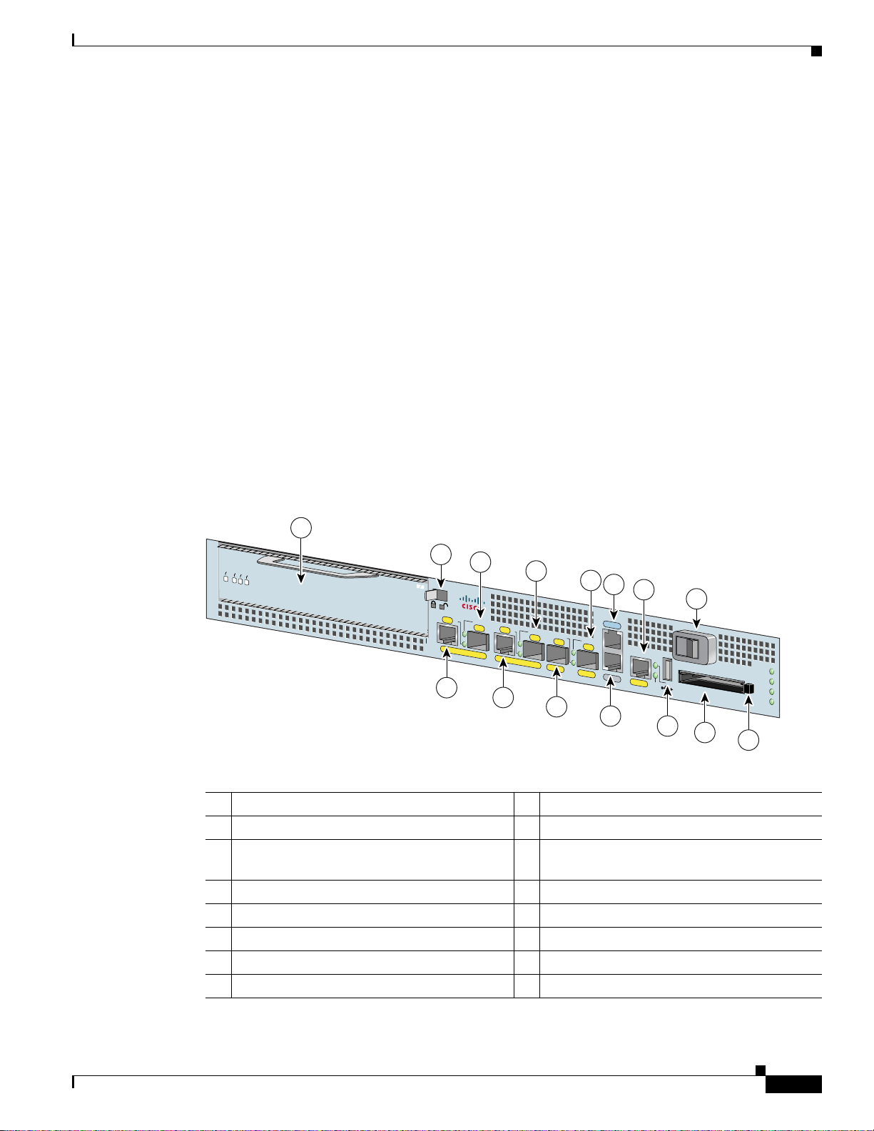
Figure 1-1 Cisco 7201 Router—Front View
1
2
ENABLED
RX CELLS
RX CARRIER
RX ALARM
ATM
PA
SLOT 1
4
Cisco
7201
RJ45
EN
LINK/ACTV
SFP
GE 0/0
3
6
RJ45
EN
LINK/ACTV
TX
SFP
RX
GE 0/1
5
LINK/ACTV
GE 0/2
7
8
9
11
CONSOLE
LINK/ACTV
SFP
TX
SFP
RX
MNGMNT USE ONLY
GE 0/3
AUX
FE 0/0
10
13
0
FE
LINK
12
COMPACT FLASH
14
1 Port adapter slot (with installed port adapter) 9 Console port
2 Port adapter lever 10 Auxiliary port
3 Gigabit Ethernet 0/0—RJ-45 port 11 Fast Ethernet 0/0—Fast Ethernet
Management port
4 Gigabit Ethernet 0/0—SFP port 12 USB port
5 Gigabit Ethernet 0/1—RJ-45 port 13 Power switch
6 Gigabit Ethernet 0/1—SFP port 14 CompactFlash Disk slot
7 Gigabit Ethernet 0/2—SFP port 15 CompactFlash Disk ejector button
8 Gigabit Ethernet 0/3—SFP port
15
ALARM
PWR OK
STATUS
CF
ACTV
170858
OL-11364-04
Cisco 7201 Installation and Configuration Guide
1-3
Page 22
Cisco 7201 Hardware Overview
Faceplate LEDs
The Cisco 7201 router LEDs and behaviors are described in this section.
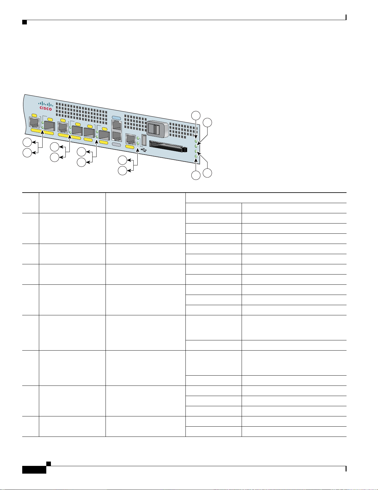
Figure 1-2 Cisco 7201 Router—Faceplate LEDs
Cisco
7201
RJ45
EN
LINK/ACTV
SFP
RJ45
EN
LINK/ACTV
LINK/ACTV
TX
SFP
RX
GE 0/0
1
2
GE 0/1
1
2
SFP
GE 0/2
1
1
LINK/ACTV
TX
GE 0/3
CONSOLE
SFP
RX
MNGMNT USE ONLY
AUX
FE 0/0
0
FE
LINK
3
4
COMPACT FLASH
ALARM
PWR OK
STATUS
CF
ACTV
Chapter 1 Overview
5
6
7
8
170859
In the Power Up State
No. LED Label LED
1 LINK/ACTV
(Link/Active)
SFP and RJ-45 ports Solid green Link with no activity
(0/0, 0/1, 0/2, 0/3)
Color—Activity Behavior Description
Flashing green Link with activity
Off No link
2 EN (Enable) (0/0, 0/1) RJ-45 ports only Solid green RJ-45 port is selected.
Off SFP port is selected.
3 USB USB port Flashing green Activity
Off No activity
4 FE 0/0 Fast Ethernet Management
port
Solid green Link with no activity
Flashing green Link with activity
Off No link
5 ALARM Alarm port Solid red On if Cisco IOS has crashed, and a
reset has happened, and remains on
until Cisco IOS is reloaded.
Off Off, the system is normal.
6 PWR OK Power Solid green The power-on is successful and the
system is attempting to boot software,
or has booted software.
Off Off, the router is in standby mode.
7 STATUS System status Solid green Cisco IOS has successfully booted.
Blinking amber ROMmon is loading.
Blinking green Cisco IOS is loading.
8 CF ACTV CompactFlash Disk Flashing green Activity
Off No activity
1-4
Cisco 7201 Installation and Configuration Guide
OL-11364-04
Page 23
Chapter 1 Overview
SFP Module Information
You may have ordered a small form-factor pluggable (SFP) module with your Cisco 7201 router. You
must install the SFP module. It is shipped separately to prevent damage during shipment. After reading
this section, use the installation instructions in the
page 4-2 to install the SFP modules.
For ease of installation, insert the SFP module in the router while it is powered down and before placing
it in a rack.
The SFP port is a 1000-Mbps optical interface in the form of an LC-type duplex port that supports IEEE
802.3z interfaces compliant with the 1000BASEX standard. Gigabit Ethernet SFP models SFP-GE-S,
SFP-GE-L, SFP-GE-Z, and SFP-GE-Fare supported in the Cisco
The cabling information is the same for all optical SFP modules.
Also see the “SFP Module Specifications and Configurations” section on page A-4, and the Gigabit
Interface Converter (GBIC) Module and S mall Form-Factor Pluggable (SFP) GBIC Module Installation
Information and Specifications document.
For optical connection cleaning information, see the Inspection and Cleaning Pr ocedures for Fiber-Optic
Connections document and the Compressed Air Cleaning Issues for Fiber-Optic Connections document.
Cisco 7201 Hardware Overview
“Removing and Installing an SFP Module” section on
7201 router, as well as the SFP-GE-T.
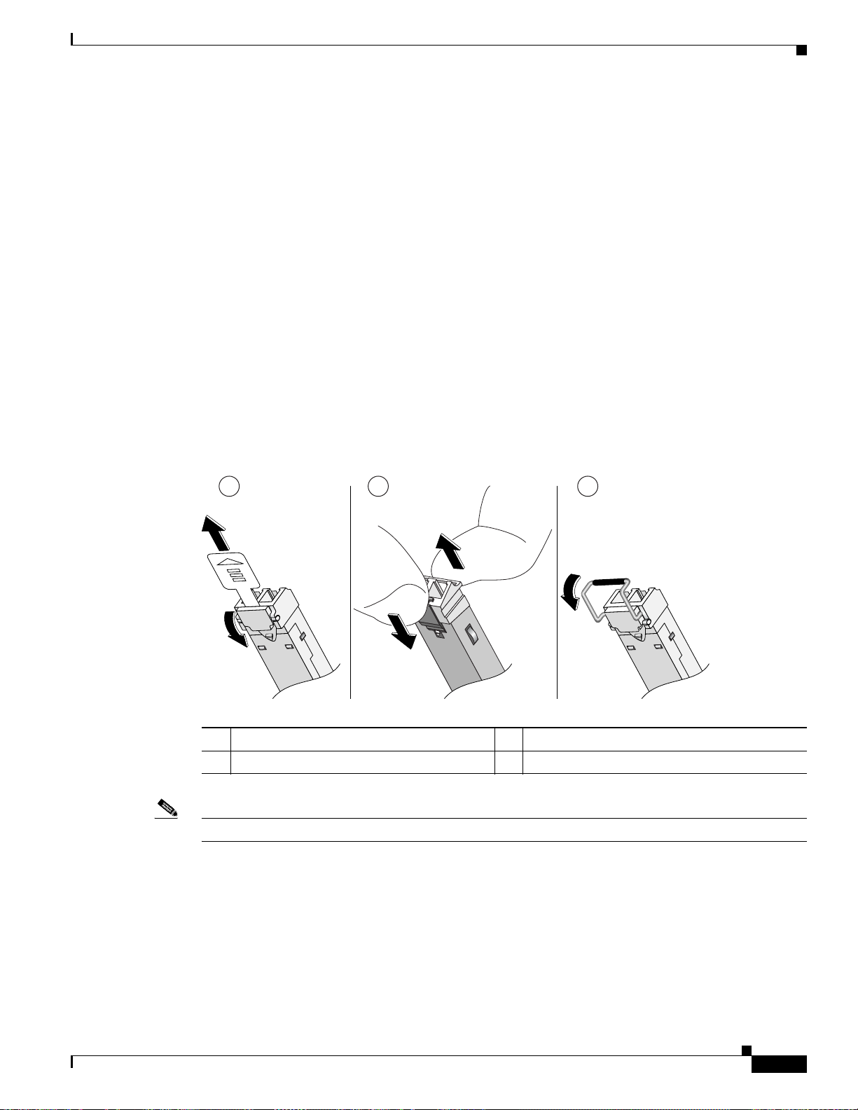
Figure 1-3 Types of SFP Module Latches
1 2 3
1 Sliding latch 3 Sw ing la tch
2 Swing and slide latch
Note The SFP module must be installed before you connect the cables to it.
80755
OL-11364-04
• The SPF module has three types of latches, which are also the removal mechanism. See Figure 1-3.
There is no correlation of the type of latch to the model (such as SX or LH/LX) or technology type
(such as Gigabit Ethernet) of SFP modules.
Always read the label on the SFP module to determine
the technology type and model.
• You can install and remove Gigabit Ethernet SFP modules with power on to the system.
Cisco 7201 Installation and Configuration Guide
1-5
Page 24

Cisco 7201 Hardware Overview
Chapter 1 Overview
Warning
Warning
Warning
Invisible laser radiation may be emitted from disconnected fibers or connectors. Do not stare into
beams or view directly with optical instruments.
Class 1 laser product.
Class 1 LED product.
• Disconnect all cables before removing or installing a Gigabit Ethernet SFP module. We strongly
• SFP modules are keyed to prevent incorrect insertion.
USB Port Information
The Cisco 7201 provides a USB port that can be used with a USB Flash memory module as secondary
storage, and can be used to store Cisco IOS images, data, and configuration files. The Cisco 720 1 USB
port can also be used with the Aladdin USB eToken Pro key. This USB device can be used for the
following functions:
• The Cisco USB Flash memory module can be used to store an image or configuration file like a
• The USB eToken Pro key by Aladdin Knowledge Systems provides a secure means to store and
Statement 1051
Statement 1008
Statement 1027
recommend that you do not install or remove t he SFP module with optical f iber cables attached t o it.
CompactFlash Disk. Unlike the Aladdin USB eToken Pro key, the Cisco USB Flash memory module
is nonsecure. See
Table A-5 on page A-4 for available USB token configurations and product
numbers.
deploy information, such as a bootstrap configuration or VPN credentials, separate from the router
chassis. The Aladdin USB eToken Pro key uses smart card technology to protect a small area of
memory and grants access using a personal identification number (PIN). When IP Security (IPSec)
VPN credentials are stored on the Aladdin USB eToken Pro key, they are safely external to the
router. When the USB eToken is inserted in a USB port, the router can pass the PIN and unlock it,
retrieving the credentials and copying them into running memory. When the Aladdin USB eToken
Pro key is removed, the router erases the credentials from running memory, ensuring that they
cannot be retrieved from the router itself.
1-6
Note For more information about the eToken Pro key by Aladdin Knowledge Systems, see the
Aladdin website at www.aladdin.com/etoken/cisco.
Note The Cisco USB Flash memory module cannot be used to boot the router. The USB drivers
exist only in Cisco IOS software, not ROM Monitor mode (ROMmon). As a result, a Cisco
IOS image must be booted to load the drivers; only then can files be copied to and from the
USB Flash memory module.
Cisco 7201 Installation and Configuration Guide
OL-11364-04
Page 25
Chapter 1 Overview
CompactFlash Disk Information
The Cisco 7201 router has one CompactFlash Disk slot that uses CompactFlash Disks. The device in this
slot is always addressed as disk0: when using Cisco
CompactFlash Disks are smaller in size than Type 2 Flash Disks but provide the same AT Attachment
(ATA) interface and equivalent functionality. This interface complies with the ANSI ATA Interface
Document X3T13.1153 D Rev.
The CompactFlash Disk has controller circuitry that allows it to emulate a hard disk and automatically
maps out bad blocks and performs automat ic block e rasure. The CompactFlash Disk also provides the
capability to allocate noncontiguous sectors, which eliminates the need for the squeeze command (which
was required with older-style linear flash memory cards to recover the space used by deleted files).
The CompactFlash Disk also supports the Cisco IOS File System feature, which provides a single
interface to all of the router’s file systems, including the Flash Disks and flash memory, as well as
network file systems such as File Transfer Protocol (FTP) and Trivial FTP (TFTP) servers.
Table A -4 on page A-3 lists the CompactFlash Disk options. Also see Appendix B, “Using the
CompactFlash Disk.”
Cisco 7201 Hardware Overview
IOS command-line interface (CLI) commands.
9 specification. CompactFlash Disks provide from 256 MB of storage.
Rear View
This section provides information about the power supp lies and fans on the rear of the Cisco 7201 router.
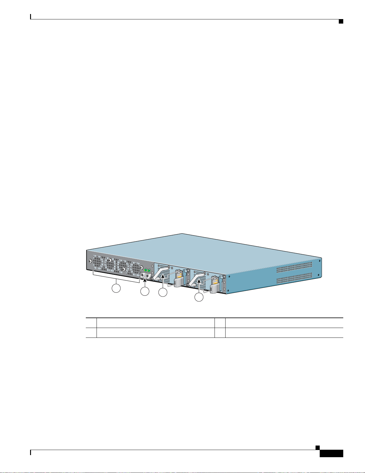
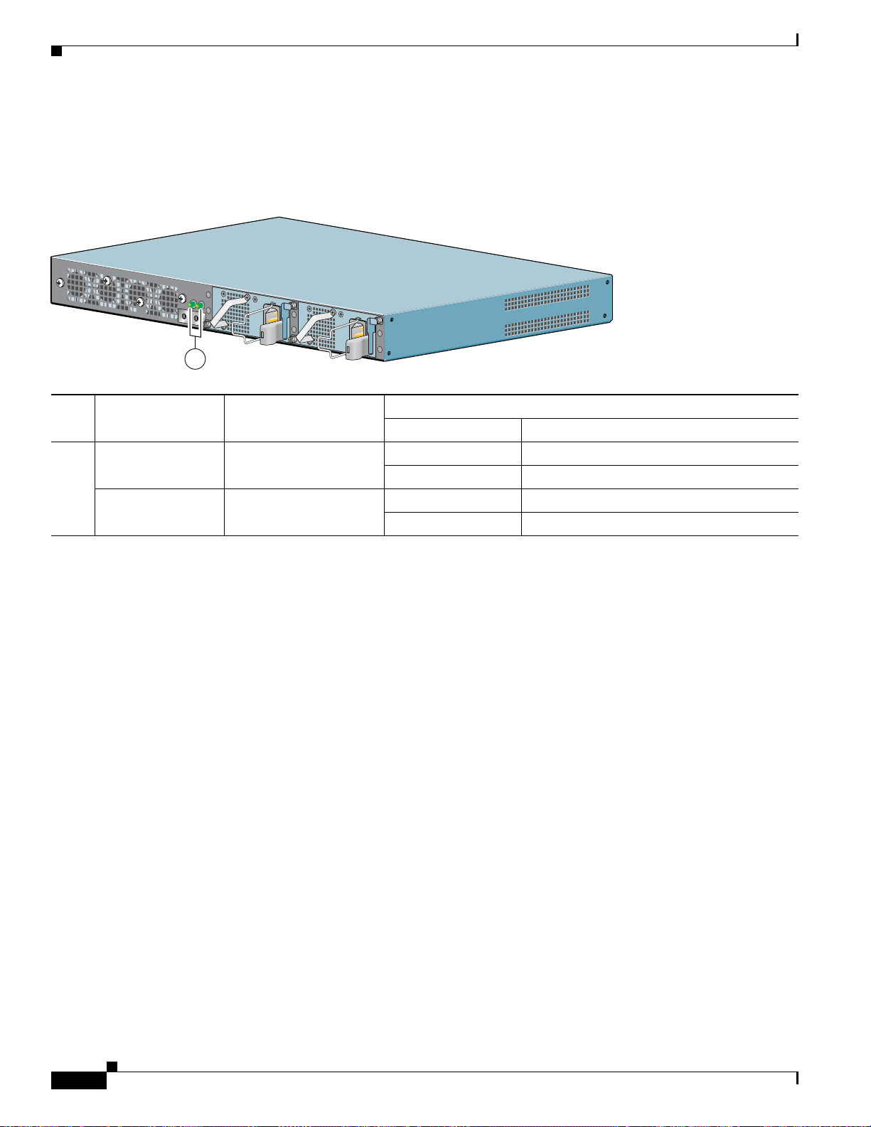
Figure 1-4 Cisco 7201—Rear V i ew
T
H
IS
U
N
IT
M
A
Y
H
A
V
E
M
O
R
E
T
H
A
N
O
N
E
P
O
W
E
R
S
U
P
P
L
Y
C
O
N
N
E
C
T
IO
N
. A
L
L
C
O
N
N
E
C
T
IO
N
S
M
U
S
T
B
E
R
E
M
O
V
E
D
T
O
D
E
-
E
N
E
R
G
IZ
E
T
H
E
U
N
IT
PWR
SLOT 1 OK
PWR
SLOT 2 OK
PWR
SLOT 1
PWR
1
2
3
SLOT 2
158675
4
1 Fans 3 Power supply slot 1
2 Chassis ground connector 4 Power supply slot 2
Four internal fans draw cooling air into the chassis and across internal components to maintain an
acceptable operating temperature. (See
Figure 1-4.) The four fans are located at the rear of the chassis,
as is the chassis grounding connector that provides a chassis ground connection for ESD equipment or
a two-hole grounding lug. Two power supplies, either two AC po wer supplies or tw o DC power supplies,
are accessed from the rear of the router.
OL-11364-04
Cisco 7201 Installation and Configuration Guide
1-7
Page 26
Cisco 7201 Hardware Overview
Power Supply LEDs
The power supply LEDs are to the left of the power supplies on the rear of the chassis.
Figure 1 -5 Power Supply LEDs
T
H
I
S
U
N
I
T
M
A
Y
H
A
V
E
M
O
R
E
T
H
A
N
O
N
E
P
O
W
E
R
S
U
P
P
L
Y
C
O
N
N
E
C
T
IO
N
. A
L
L
C
O
N
N
E
C
T
I
O
N
S
M
U
S
T
B
E
R
E
M
O
V
E
D
T
O
D
E
-
E
N
E
R
G
I
Z
E
T
H
E
U
N
I
T
PWR
SLOT 1 OK
PWR
SLOT 2 OK
PWR
SLOT 1
PWR
SLOT 2
1
In the Power Up State
No. LED Label LED
1 PWR Slot 1 Power supply activity Green Active
PWR Slot 2 Power supply activity Green Active
Color—Activity Behavior Description
Off Off; the router is in standby mode.
Off Off; the router is in standby mode.
Chapter 1 Overview
158674
1-8
Cisco 7201 Installation and Configuration Guide
OL-11364-04
Page 27
Chapter 1 Overview
Interior View
Cisco 7201 Hardware Overview
This section describes the Cisco 7201 interior components and their locations.
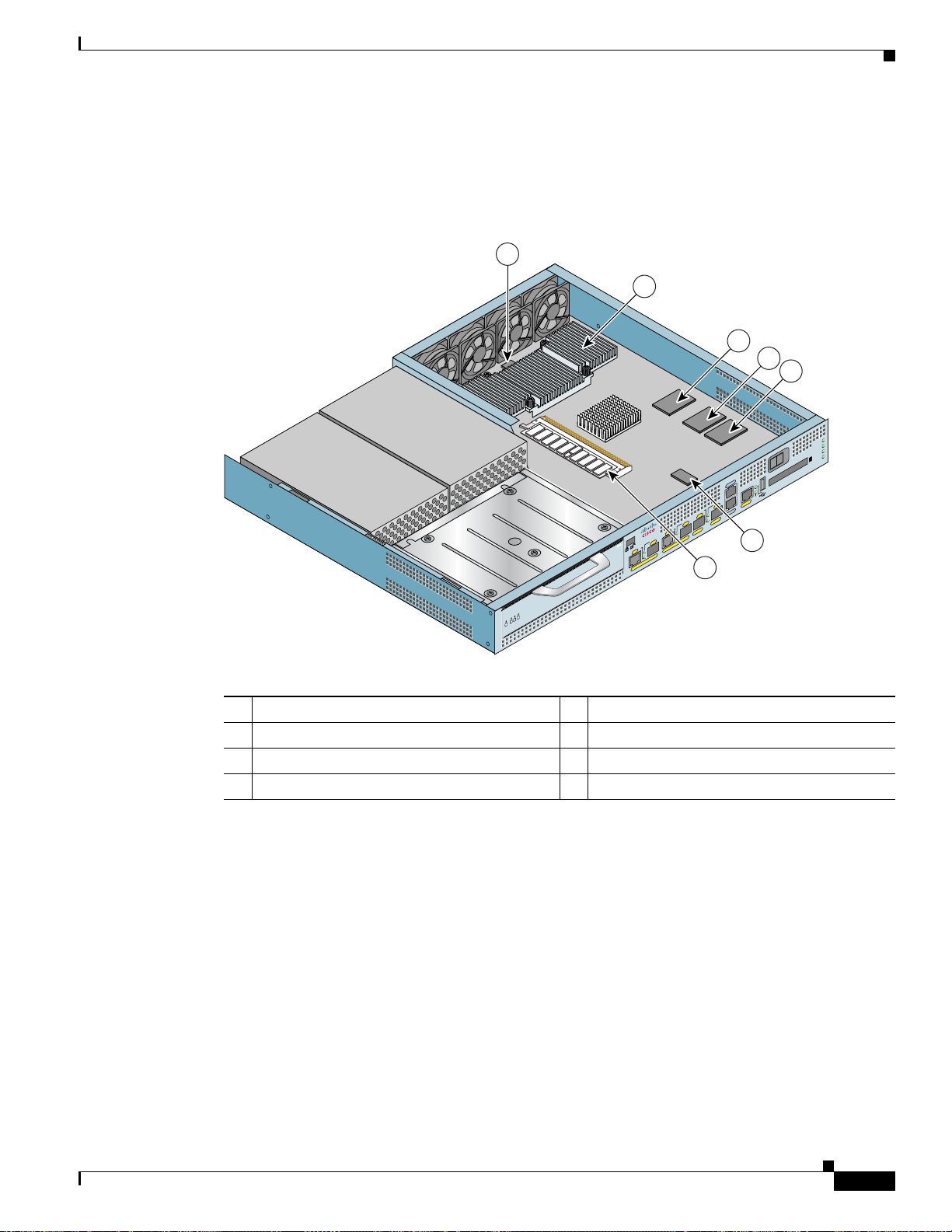
Figure 1-6 Cisco 7201 Router—Interior View
1
2
0
T
E
N
R
E
H
T
IN
E
L
IT
B
A
IG
G
X
T
N
E
5
4
J
R
CTV
/1
R
0
T
E
LINK/A
N
R
SFP
E
X
H
K
R
T
IN
E
L
TX
IT
IC
B
B
A
G
IG
G
CTV
X
T
K/A
LIN
SFP
N
E
5
J4
R
0
/
X
0
K/ACTV
T
R
E
N
R
E
X
H
K
R
T
IN
E
L
IT
IC
B
B
A
G
IG
G
X
T
N
E
5
4
J
R
1
7201
T
LO
S
LINK/ACTV
Cisco
SFP
ATM
N
ATM
E
RJ45
O 7301
GE 0/0
CISC
PA
T 1
SLO
GE 0/3
LIN
SFP
TX
EN
E 0/2
45
G
RJ
E 0/1
G
7
3
4
5
z
H
/60
0
A
5
, 5
=
A
V
0
, 2
V
- 6
40
8
-2
, 4
0
0
A
1
9
=
V
24
M
BA
ALAR
K
R O
PW
S
STATU
CF
TV
AC
M
R
A
L
A
E
L
O
S
N
O
C
X
U
A
OLE
NS
/2
CO
SE O
U
NT
X
K
R
M
IC
MNG
B
G
X
FE 0/0
UX
A
H
S
S
A
U
L
T
T
A
T
C
F
S
A
T
P
M
C
O
A
C
H
P
S
A
M
L
F
O
C
NLY
0
FE
K
LIN
170955
6
System Board
RM
RRIER
D
E
ED
RX ALARM
L
RX ALA
L
B
CELLS
RX CARRIER
RX CA
B
A
RX CELLS
A
RX
N
N
E
E
1 Temperature sensor (outlet—U20) 5 Flash memory (U13)
2 Freescale 7448 processor 6 Temperature sensor (inlet—U12)
3 Boot ROM (U24) 7 DIMM (U16)
4 Flash memory (U19)
On the underside of the board is NVRAM (U77) and flash memory (U67, U70).
Internally, the system board contains the following components:
• One DDR-SDRAM memory module (DIMM) for providing code, data, and packet storage
• The Freescale 7448 processor
• Marvel Discovery III—Hardware logic to interconnect the processor, double data rate synchronous
dynamic random-access memory (DDR-SDRAM), dual PCI /PCI-X buses, three direct-interface
Gigabit Ethernet interfaces, and a generic device bus
OL-11364-04
Cisco 7201 Installation and Configuration Guide
1-9
Page 28

Cisco 7201 Hardware Overview
• Cache memory
• Four Gigabit Ethernet interfaces (six ports: four SFP [optical] and two RJ-45s [copper]). Only four
• One Fast Ethernet Management port
• A CompactFlash Disk for storing the default Cisco IOS software image
• Auxiliary port with full data terminal equipment (DTE) functionality
• Console port with full data communications equipment (DCE) functional ity
• Boot ROM for storing sufficient code for booting the Cisco IOS software
• Flash memory for storing the boot helper (boot loader) image
• NVRAM for storing the system configuration and environmental monitoring logs. NVRAM uses
• Two environmental sensors for monitoring the internal temperature of the chassis
Chapter 1 Overview
The processor system has two levels of cache: primary and secondary cache that are internal to the
microprocessor with secondary unified cache for data and instruction.
ports are available at the same time.
lithium batteries to maintain its contents when disconnected from power.
System Management Functions
The Cisco 7201 processor system performs the following system management functions:
• Sending and receiving routing protocol updates
• Managing tables, caches, and buffers
• Monitoring interface and environmental status
• Providing Simple Network Management Protocol (SNMP) management through the console and
Telnet interface
• Accounting for and switching of data traffic
• Booting and reloading images
• Managing the port adapter (including recognition and initialization during online insertion and
removal)
The Cisco 7201 router supports multiprotocol, multimedia routing and bridging with a wide variety of
protocols and port adapters.
1-10
Cisco 7201 Installation and Configuration Guide
OL-11364-04
Page 29

Chapter 1 Overview
Checking the Shipping Container Contents
Checking the Shipping Container Contents
Use the Cisco 7201 components list to check the contents of the Cisco 7201 router shipping container.
Do not discard the shipping container. You need the container if you move or ship the Cisco 7201 rout er
in the future.
Tab l e 1-1 Cisco 7201 Components List
Component Description Received
Chassis Cisco 7201 chassis configured with dual AC or dual DC power supplies and a port
adapter blank panel if a port adapter has not been ordered.
Accessories:
• Rack-mount and
cable-management kit
The following accessories might arriv e in separate shipping containers or might sh ip
installed:
Two rack-mount brackets, one cable-management bracket, four 6-32 x 0.25-in.
screws to secure the rack-mount brackets to th e ch assis, four 10 -32 or 12- 24 screws
to secure the rack-mount brackets to a 19-inch rack, or a 21–23-inch rack, and one
M4 x 20-mm screw to attach the cable-management bracket to the rack-mount
bracket
• Power cables
• Documentation
Optional Equipment
Note Most Cisco documentation is online or on the Cisco Documentation DVD. Documentation that ships
with your Cisco 7201 router includes the Re gulat ory Compliance and Safety I nformation for Cisco
Series Routers document, and the Cisco 7201 Router Documentation Roadmap that contains
documentation titles and the URLs to them online. See also the
page xvii.
An AC power cable, if an AC power supply was ordered
Router hardware and software documentation a nd the Cisco D ocument ation DVD
package
An optional Cisco USB Flash memory module, if ordered
Exam ples : Port adapter , SFP modules, CompactFlash Disk, network interface cables,
USB memory modules, transceivers, special connectors, and so on
Cisco 7201 Router Installation Checklist
To assist you with your installation and to provide a historical record of what was done by whom,
photocopy the Cisco 7201 Router Installation Checklist,
procedure or verification is completed. When the checklist is completed, place it in your site log along
with the other records for your new router.
Information on replacing internal field-repl aceable units (FRUs) is found in Chapter 4, “Replacing Cisco
7201 Field-Replaceable Units.”
7200
“Related Documentation” section on
Table 1- 2 on pa ge 1-12. Indicate when each
OL-11364-04
Cisco 7201 Installation and Configuration Guide
1-11
Page 30

Cisco 7201 Router Installation Checklist
Tab l e 1-2 Cisco 7201 Router Installation Checklist
Task
Date router received
Router and all accessories unpacked
Types and numbers of interfaces verified
Safety recommendations and guidelines reviewed
Installation Checklist copied
Site log established and background information entered
Site power voltages verified
Site environmental specifications verified
Required passwords, IP addresses, device names, and so on, available
Required tools available
Network connection equipment available
Router mounted in rack (optional)
Cable-management bracket installed (optional but recommended)
AC power cable(s) connected to AC source(s) and router; AC cable-retention clip secured
DC power cable(s) connected to DC source(s) and router
Network interface cables and devices connected
ASCII terminal attached to console port
Console port set for 9600 baud, 8 data bits, no parity, and 1 stop bits (9600 8N1)
System power turned on
System boot complete (STATUS LED is on)
I/O ports and port adapter are operational (see Figure 1-2 for specific LED information)
Correct hardware configuration displayed after system banner appears
Chapter 1 Overview
Verified
By
Date
1-12
Cisco 7201 Installation and Configuration Guide
OL-11364-04
Page 31

CHAPTER
2
Installing the Cisco 7201 Router
This chapter explains how to install a Cisco 7201 router in a rack in a general tabletop or workbench
installation, how to attach cables, and how to power on the router.
This chapter contains the following sections:
• Preparing to Install the Cisco 7201 Router, page 2-1
• Installing the Router, page 2-5
• Attaching a Chassis Ground Connection, page 2-12
• Installing a Port Adapter, USB Flash Memory Module, or SFP Module That Did Not Ship in the
System, page 2-14
• Connecting Port Adapter Cables, page 2-14
• Connecting I/O Cables, page 2-14
• Using the Cable-Management B racket, page 2-23
• Connecting Power, page 2-24
The Cisco 7201 router operates as either a tabletop or a rack-mounted unit. A rack-mount kit is standard
equipment included with the Cisco 7201 router when it is shipped from the factory. The kit provides the
hardware needed to mount the router in a 19-inch equipment rack or a 23-inch equipment rack.
If you are not rack-mounting your Cisco 7201 router, place it on a sturdy tabletop or platform.
Preparing to Install the Cisco 7201 Router
Before installing your Cisco 7201 router, you should consider the power and cabling requirements that
must be in place at your installation site, the equipment you need to install the router, and the
environmental conditions your installation site must meet to maintain normal operation. This section
guides you through the process of preparing for your router installation and the installation in a rack.
This section contains the following topics:
• Site Preparation and Unpacking, page 2-2
• Tools and Parts Required, page 2-3
• Electrical Equipment Guidelines, page 2-4
• Preventing Electrostatic Discharge Damage, page 2-4
• Site Requirement Guidelines, page 2-4
Cisco 7201 Installation and Configuration Guide
OL-11364-04
2-1
Page 32

Preparing to Install the Cisco 7201 Router
Figure 2-1 Dimensions of Cisco 7201 Router
Chapter 2 Installing the Cisco 7201 Router
2
1
3
230623
1 19.17 in. (48.69 cm) 3 16.2 in. (41.20 cm)
2 17.3 in. (43.94 cm)
Table 2-1 provides dimensions and weight information.
Tab l e 2-1 Cisco 7201 Router Dimensions and Weight
Cisco 7201
Dimensions Height—1.73 in. (4.39 cm)
Width—17.3 in. (43.94 cm)
Depth—16.2 in. (41.20 cm)
Weight Chassis fully configured with a port adapter ~ 16.5 lb (7.48 kg)
Site Preparation and Unpacking
• Lift the router safely out of the packing container.
• Ensure the power service at the site is suitable for the router you are installing.
• Check the packing slip to ensure that all the proper components are present.
• Locate and have accessible the Site Log for recording information about this installation.
Cisco 7201 Installation and Configuration Guide
2-2
OL-11364-04
Page 33

Chapter 2 Installing the Cisco 7201 Router
Tools and Parts Required
Your Cisco 7201 chassis is fully assembled at the factory; no assem bly is required. However, you need
the following tools and equipment to install the chassis and the rack-mount and cable-management kit,
and the DC power supplies:
• Number 2 Phillips screwdriver
• A 3/16-inch flat-blade screwdriver
• Tape measure (optional)
• Level (optional)
• Chassis grounding lug and wires:
–
A grounding lug with two number-10 screw holes with a 0.63-inch (16.002-mm) spacing
between them
–
A wire receptacle large enough to accept a 6-AWG multistrand, copper wire
–
Two Phillips machine screws with locking washers—M5 (metric), 0.031-inch (.08-mm) pitch,
0.315-inch (8-mm) length
–
A crimping tool to fit the grounding lug wire receptacle
Preparing to Install the Cisco 7201 Router
–
A wire stripper
–
One grounding wire—6-AWG, 0.162-inch (4.115-mm) diameter, with approximately
0.108-inch (2.743-mm) insulation, for a total wire diameter of approximately 0.27 inches
(6.858
mm). The wire length depends on your router location and site environment.
• The rack-mount and cable-management kit (RCKMNT-7201) includes the following parts:
–
Two rack-mount brackets for mounting the chassis in the rack
–
One cable-management bracket
–
Four 6-32 x 0.25-in. screws to secure the rack-mount brackets to the chassis
–
Two M3 x 8-mm screws to secure the rack-mount brackets to the chassis
–
Four 10-32 or 12-24 screws to secure the rack-mount brackets to a 19-inch or 21–23-inch rack
–
One M4 x 20-mm screw to attach the cable-management bracket to the rack-mount bracket
• For DC power supplies installation, the following parts:
–
Ratcheting torque screwdriver with a Phillips head that exerts up to 15 pound force-inches
(lbf in.) or 240 ounce force-inches (ozf in.) of pressure
–
Panduit crimping tool with optional controlled cycle mechanism
–
18-gauge copper ground wire (insulated or noninsulated)
–
Four leads of 18-gauge copper wire
–
Wire-stripping tool for stripping 18-gauge wire
In addition, you might need the following external equipment:
• Ethernet transceiver
OL-11364-04
• Token Ring multistation access unit (MSAU)
• ESD-preventative wrist strap
• Power cords
• Appropriate cables to connect the router to the network, console, and auxiliary ports
Cisco 7201 Installation and Configuration Guide
2-3
Page 34

Preparing to Install the Cisco 7201 Router
• Optional Cisco USB Flash memory module or Aladdin USB eToken Pro key
• Straight-through or roll-over cable for use with Fast Ethernet Management port
Electrical Equipment Guidelines
The port adapter is designed to be removed and replaced while t he system is o perating w ithout
presenting an electrical hazard or damage to the system.
Preventing Electrostatic Discharge Damage
Electrostatic discharge (ESD) damage, which occurs when electronic cards or components are
improperly handled, can result in complete or inter mittent system failures. Each por t adapter consists of
a printed circuit board that is fixed in a metal carrier. Electromagnetic interference (EMI) shielding,
connectors, and a handle are integral components of the carrier. Although the carrier helps protect the
boards, use an antistatic strap whenever handling the port adapter. Handle the carriers by the handle and
the carrier edges only; never touch the boards or connector pins.
Chapter 2 Installing the Cisco 7201 Router
Site Requirement Guidelines
Warning
Before you install, operate, or service the system, read the Regulatory Compliance and Safety
Information for Cisco 7200 Series Routers publication. This document provides important safety
information you should know before working with the system
The environmental monitoring functionality in the Cisco 7201 router protects the system and
components from potential damage from overvoltage and overtemperature conditions. To ensure normal
operation and avoid unnecessary maintenance, plan your site configuration and prepare your site befo re
installation. After installation, make sure the site maintains an ambient temperature of 32•F through
104•F (0•C through 40•C), and keep the area around the chassis as free from dust as is practical.
Planning a proper location for the Cisco 7201 router and the layout of your equipment rack or wiring
closet is essential for successful system operation. Equipment placed too close together or inadequately
ventilated can cause system overtemperature conditions. In addition, chassis panels made inaccessible
by poor equipment placement can make system maintenance dif ficult. F ollowing are precauti ons that can
help avoid problems during installation and ongoing operation.
Figure 2-2 Airflow Through the Chassis
D
LE
B
A
N
E
RX CELLS
RX CARRIER
RX ALARM
ATM
RJ45
PA
SLOT 1
. Statement 200
Cisco
7201
EN
LINK/ACTV
SFP
RJ45
EN
GE 0/0
GE 0/1
CONSOLE
LINK/ACTV
LINK/ACTV
TX
SFP
RX
LINK/ACTV
SFP
TX
SFP
RX
MNGMNT USE ONLY
GE 0/2
GE 0/3
AUX
FE 0/0
0
FE
LINK
COMPACT FLASH
ALARM
PWR OK
STATUS
CF
ACTV
170875
2-4
Cisco 7201 Installation and Configuration Guide
OL-11364-04
Page 35

Chapter 2 Installing the Cisco 7201 Router
When you plan the location and layout of your equipment rack or wiring closet, you need to consider
how air flows through your router. The Cisco 7201 router draws cooling air in through the intake vents
on the front of the chassis and moves the air across the internal components and out the exhaust vents
on the rear of the chassis.
Temperature sensors on the system board monitor the internal air temperature and send warning
messages when the internal air temperature approaches a specified threshold. If the internal temperature
exceeds the specified threshold, the system environmental monitor shuts down all internal power to
prevent equipment damage from excessive heat. (See the
Functions” section on page 3-4 for temperature threshold information.)
Installing the Router
This section explains how to install a Cisco 7201 ro uter in a g eneral ta bletop o r workbenc h inst allat ion
and in a rack, and how to attach I/O, port adapter, and power cables. This sect ion contains the following
topics:
• General Tabletop or Work bench Ins tallation , page 2-5
• Rack-Mounting a Cisco 7201 Router, page 2-6
Installing the Router
Figure 2-2 shows airflow through the router.
“Environmental Monitoring and Reporting
• Attaching the Chassis Rack-Mount and Cable-Management Brackets, page 2-7
• Installing the Chassis in the Rack, page 2-9
General Tabletop or Workbench Installation
The router should already be in the area where you will install it, and your installation location s hould
already be determined. If not, see the
and the “Site Requirement Guidelines” section on page 2-4.
When installing a Cisco 7201 router on a workbench or tabletop, ensure that the surface is clean and in
a safe location and that you have considered the following:
• The router requires at least 3 inches (7.62 cm) of clearance at the inlet and exhaust vents (the front
and back sides of the router).
• The router should be installed off the floor. (Dust that accumulates on the floor is drawn into the
interior of the router by the cooling fans. Ex cessiv e dust inside the router can cause ov ertemperature
conditions and component failures.)
• There must be approximately 19 inches (48.26 cm) of clearance at the front and rear of the router
for installing and replacing router parts—such as the port adapter, SFP module, USB module, or
CompactFlash Disk—or accessing network cables or equipment.
• A port adapter blank panel is installed if a port adapter or service adapter is not in place.
• The router will receive adequate ventilation (it is not being installed in an enclosed cabinet where
ventilation is inadequate).
“Preparing to Install the Cisco 7201 Router” section on page 2-1,
OL-11364-04
• If you plan to install the cable-management bracket, unpack and ha v e handy the cable-management
bracket and one M4 x 20-mm screw.
• An adequate chassis ground (earth) connection exists for your router chassis.
Cisco 7201 Installation and Configuration Guide
2-5
Page 36

Installing the Router
Chapter 2 Installing the Cisco 7201 Router
Warning
This product relies on the building’ s installation for short-circuit (overcurrent) protection. Ensure that
the protective device is rated not greater than: 120 VAC, 20A U.S. (240 VAC, 10A international).
Statement 1005
Following are the steps for installing a Cisco 7201 router on a workbench or tabletop:
Step 1 Remove any debris and dust from the tabletop or workbench, as well as the surrounding area. Also make
sure your path between the router and its new location is unobstructed.
Step 2 On the chassis, ensure that the port adapter lever is in the locked position.
Step 3 Lift the chassis by placing your hands around the chassis sides and lifting the chassis from underneath.
To prevent injury, avoid sudden twists or moves.
Step 4 Place the router on the tabletop or workbench.
Step 5 Ensure that there is at least 3 inches (7.62 cm) of clearance at the inlet and exhaust vents of the router
and no exhaust air from other equipment will be drawn into the chassis. Also, ensure that there is
approximately 19 inches (48.26 cm) of clearance at the front and rear of the chassis.
This completes the general tabletop or workbench installation. Go to the “Attaching a Chassis Ground
Connection” section on page 2-12 for the next step in installing the Cisco 7201 router.
Rack-Mounting a Cisco 7201 Router
The chassis mounts to two rack posts with brackets that attach to either the front or the rear sides of the
chassis. The inside width between the two posts or mounting strips (left and right) must be at least
19 inches (48.26 cm).
Some equipment racks provide a power strip along the length of one of the mounting strips. Figure 2-7
shows a typical four-post eq uipment rack with a po wer strip along one of the back post s. If your rack has
this feature, consider the position of the strip when planning fastener points to ensure that you will be
able to pull the port adapter, SFP module, USB module, or CompactFlash Disk straight out of their
respective slots.
The inlet and exhaust ports for cooling air are located on the front and rear of the chassis, respectively,
so multiple routers can be stacked in a rack with little or no vertical clearance.
Before beginning the installation, determine the type of rack yo u are u sing and wh ether o r not you w ant
the chassis front- or rear-mounted.
Note To use the cable-management bracket with the Cisco 7201 router rear-mounted, you must purchase a
second rack-mount kit, attach a rack-mount bracket to the left front of the chassis, and attach the
cable-management bracket to it. See the
“ Attaching the Cable-Management Bracket” section on page 2-8
for cable-management bracket installation instructions.
2-6
Cisco 7201 Installation and Configuration Guide
OL-11364-04
Page 37

Chapter 2 Installing the Cisco 7201 Router
Installing the Router
Attaching the Chassis Rack-Mount and Cable-Management Brackets
This section explains how to install the rack-mount and cable-management brackets at the front and the
rear of a Cisco 7201 router. Before installing the chassis in the rack, you must install a rack-mount
bracket on each side of the front or rear of the chassis.
The parts and tools required for installing the rack-mount brackets and cable-management bracket are
listed in the
Installing Rack-Mount Brackets on the Front of the Chassis
Figure 2-3 Attaching the Rack-Mount Brackets to the Front of the Chassis
“Tools and Parts Required” section on page 2-3.
D
R
E
IE
L
LS
M
R
L
B
R
R
E
A
A
LA
C
N
C
X
E
A
X
R
X
R
R
A
T
M
Cisco 7201
RJ45
EN
L
INK
/ACT
V
SF
P
RJ45
EN
LINK
PA
SLO
T 1
TX
G
E
0/0
G
E 0/1
CO
NSO
/A
CT
V
S
FP
LE
LINK
/A
C
TV
R
X
LIN
S
K/A
FP
C
TV
T
X
S
FP
R
X
M
N
G
M
N
T U
S
E O
N
G
E 0/2
LY
G
E
0/3
AU
X
FE 0/0
0
F
E
L
INK
ALAR
M
PW
R O
K
STATUS
C
O
M
PA
CT FLASH
CF
AC
T
V
281124
2 31
1 Rack-mount bracket 3 Two M3 x 8-mm screws
2 Four 6-32 x 0.25-in. screws
Figure 2-3 shows the brackets being attached for a front rack-mount.
T o install the rack-mount and cable-management brackets on a Cisco 7201 r outer for a front rack-mount
configuration, complete the following steps:
Step 1 Locate the threaded holes in the front sides of the chassis.
Step 2 Align the rack-mount bracket to the rack-mount bracket holes on the side of the router.
Step 3 Remove any existing cover screws from the front sides of the chassis that align with the rack-mount
bracket holes and then realign the bracket. (You should have to remove one cover screw from each side
of the chassis.)
Step 4 Insert and tighten two 6-32 x 0.25-in. screws in the two holes nearest the front of the chassis.
Step 5 Insert and tighten the longer M3 x 8-mm screw in the hole nearest the rear of the chassis. (This screw
replaces the cover screw that you removed in Step 3.)
Step 6 Repeat Step 1 through Step 5 on the other si de of the router.
OL-11364-04
This completes the steps for attaching the rack-mount brackets to the Cisco 7201 router.
Cisco 7201 Installation and Configuration Guide
2-7
Page 38

Installing the Router
To install the cable-management bracket, go to the “Attaching the Cable-Management Bracket” section
on page 2-8. If you are not installing the cable-management bracket, go to the “Installing the Chassis in
the Rack” section on page 2-9.
Attaching the Cable-Management Bracket
Figure 2-4 Installing the Cable-Management Bracket
1
ENABLED
RX CELLS
RX CARRIER
Chapter 2 Installing the Cisco 7201 Router
RX ALARM
2
1 Cable-management bracket 2 M4 x 20-mm screw
Step 1 Align the cable-management bracket to the rack-mount bracket on the left side of the Cisco 72 01 router.
Step 2 Using a Phillips screwdriver and the M4 x 20-mm screw, thread and tighten the screw to the
cable-management bracket.
This completes the procedure for installing the cable-management bracket on a Cisco 7201 router for a
front rack-mount configuration. Go to the
“Installing the Chassis in the Rack” section on page 2-9.
Installing Rack-Mount Brackets on the Rear of the Chassis
Figure 2-5 Attaching the Rack-Mount Brackets to the Rear of the Chassis
ENABLED
RX CELLS
RX CARRIER
RX ALARM
ATM
Cisco 7201
R
J
4
5
E
N
L
IN
K
/A
C
T
V
S
F
P
R
J4
5
E
N
T
P
A
S
L
O
T
1
X
G
E
0
/0
G
E
0/1
C
O
N
S
O
L
L
IN
K
/A
C
T
S
F
P
E
V
L
IN
K
/A
C
T
V
R
X
L
IN
S
K
F
/A
P
C
T
V
T
X
S
F
P
R
X
M
N
G
M
N
T
U
S
E
O
N
G
E
0
/2
LY
G
E
0
/3
A
U
X
F
E
0
0
/0
F
E
L
IN
K
COMPACT FLASH
170862
3
2
A
L
A
R
M
P
W
R
O
K
S
T
A
T
U
S
C
F
A
C
T
V
1
281125
2-8
1 Rack-mount bracket 3 Two M3 x 8-mm screws
2 Four 6-32 x 0.25-in. screws
Cisco 7201 Installation and Configuration Guide
OL-11364-04
Page 39

Chapter 2 Installing the Cisco 7201 Router
To install the rack-mount and cable-management brackets on a Cisco 7201 router for a rear rack-mount
configuration, complete the following steps:
Step 1 Locate the threaded holes in the rear sides of the chassis.
Step 2 Align the rack-mount bracket to the rack-mount bracket holes on the side of the router.
Step 3 Remove any existing cover screws from the front sides of the chassis that align with the rack-mount
bracket holes and then realign the bracket. (You should have to remove one cover screw from each side
of the chassis.)
Step 4 Insert and tighten two 6-32 x 0.25-in. screws in the two holes nearest the rear of the chassis.
Step 5 Insert and tighten the longer M3 x 8-mm screw in the hole nearest the front of the chassis. (This screw
replaces the cover screw that you removed in Step 3.)
Step 6 Repeat Step 1 through Step 5 on the other si de of the router.
Note To use the cable-management bracket with the Cisco 7201 router rear-mounted, you must purchase a
second rack-mount kit, attach a rack-mount bracket to the left front of the chassis, and attach the
cable-management bracket to it. See the
for cable-management bracket installation instructions.
Installing the Router
“ Attaching the Cable-Management Bracket” section on page 2-8
This completes the procedure for installing the rack-mo unt brack ets and cable-management brack ets on
a Cisco 7201 router for a rear rack-mount configuration. Go to the
section on page 2-9.
Installing the Chassis in the Rack
After installing the brackets on the chassis, you mount the router b y securing the rack-mount brackets to
two posts or mounting strips in the rack using the four screws provided. Because the brackets support
the weight of the entire chassis, be sure to use all four screws to fasten the two rack-mount brackets to
the rack posts.
two-post and four-post equipment racks.
We recommend that you allow at least 1 or 2 inches (2.54 or 5.08 cm) of vertical clearance between the
router and any equipment directly above and below it.
To install the chassis in the r ack, comp lete th e following steps:
Step 1 On the chassis, ensure that the port adapter lever is in the locked position, and that the CompactFlash
Disk, USB module, and any SFP modules are installed.
Step 2 Make sure that your path to the rack is unobstructed. If the rack is on wheels, ensure that the brakes are
engaged or that the rack is otherwise st abilized .
Step 3 Position the chassis so that the front end is closest to you. Lift the chassis and move it to the rack. To
prevent injury, avoid sudden twists or moves.
Step 4 Slide the chassis into the rack, pushing it back until the brackets (installed at the front or rear of the
chassis) meet the mounting strips or posts on both sides of the equipment rack.
Figure 2-6 on page 2-10 and Figure 2-7 on page 2-11 show typical inst allations i n
“Installing the Chassis in the Rack”
OL-11364-04
Cisco 7201 Installation and Configuration Guide
2-9
Page 40

Installing the Router
For two-post rack installation, go to the “Two-Post Rack Installation” section on page 2-10.
For four-post rack installation, go to the “Four-Post Rack Installation” section on page 2-11.
Two-Post Rack Installation
Note Inner clearance (the width between the inner sides of the two posts or rails) must be at least 19 inches
(48.26
cm). The height of the chassis is 1.73 inches (4.39 cm). Airflow through the chassis is from front
to back.
Figure 2-6 Installing the Cisco 7201 Router in a Two-P ost Rack
BLE
A
EN
Chapter 2 Installing the Cisco 7201 Router
1
D
RX CELLS
RX CARRIER
RX ALARM
2
ATM
Cisco 7201
R
J
4
5
E
N
L
IN
K
/A
C
T
V
S
F
P
R
J
4
5
E
N
P
A
S
L
O
T
1
G
E
0
/0
G
C
O
N
S
O
L
L
T
X
E
0
/1
E
IN
K
/A
C
T
V
L
IN
K
/A
S
C
F
T
P
V
R
X
L
IN
S
K
F
/A
P
C
T
V
T
X
S
F
P
R
X
M
N
G
M
N
T
U
S
E
O
N
L
G
E
0
/2
Y
G
E
0
/
3
A
U
X
F
E
0
/0
F
E
L
IN
K
A
L
A
R
M
P
W
R
O
0
K
S
T
A
T
U
S
C
O
M
P
A
C
T
F
L
A
S
H
C
F
A
C
T
V
3
281126
1 Two-post rack 3 Four 10-32 or 12-24 screws
2 Screw hole for the cable-management
bracket
Step 1 Make sure that the p ort adapte r lever is in the locked position .
Step 2 Make sure the rack brakes are locked or the rack is stabilized.
Step 3 Position the router so the front is closest to you and lift it carefully into the rack. To prevent injury , a v oid
any sudden twists or moves.
Step 4 Slide the chassis into the rack, pushing it back until the brackets meet the mounting strips or posts on
both sides of the rack.
Step 5 Keeping the brackets flush against the posts or mounting strips, align the holes in the brackets with the
holes on the rack or mounting strip.
Step 6 For each bracket, insert and tighten two 10-32 or 12-24 screws to the rack.
This completes the procedure for installing the chassis in the rack. Proceed to the “Attaching a Chassis
Ground Connection” section on page 2-12 to continue the installation.
2-10
Cisco 7201 Installation and Configuration Guide
OL-11364-04
Page 41

Chapter 2 Installing the Cisco 7201 Router
Four-Post Rack Installation
Note Inner clearance (the width between the inner sides of the two posts or rails) must be at least 19 inches
(48.26
cm). The height of the chassis is 1.73 inches (4.39 cm). Airflow through the chassis is from front
to back.
Figure 2-7 Installing the Cisco 7201 Router in a Four-Post Rack
1
D
E
L
B
C
NA
E
RX
Installing the Router
M
R
ELLS
ARRIER
LA
C
A
X
R
RX
2
ATM
C
isco
7201
R
J
4
5
E
N
L
IN
K
/A
C
T
V
S
F
P
R
J
4
5
E
P
A
S
L
N
O
T
1
G
E
0
/0
G
E
0
C
O
N
S
O
L
L
IN
T
X
/1
E
K
/A
C
T
V
L
IN
K
/A
C
S
F
T
P
V
R
X
L
IN
S
K
F
/A
P
C
T
V
T
X
S
F
P
R
X
M
N
G
M
N
T
U
S
E
O
N
L
G
E
0
/2
Y
G
E
0
/3
A
U
X
F
E
0
0
/0
F
E
L
IN
K
CO
MPACT FLASH
A
L
A
R
M
P
W
R
O
K
S
T
A
T
U
S
C
F
A
C
T
V
3
1 Four-post rack 3 Four 10-32 or 12-24 screws
2 Screw hole for the cable-management bracket
Step 1 Make sure that the p ort adapte r lever is in the locked position .
Step 2 Make sure the rack brakes are locked or the rack is stabilized.
Step 3 Position the router so the front is closest to you and lift it carefully into the rack. To prevent injury , a void
any sudden twists or moves.
Step 4 Slide the chassis into the rack, pushing it ba ck until the brackets meet the mounti ng strips or posts on
both sides of the rack.
Step 5 Keeping the brackets flush against the posts or mounting strips, align the holes in the brackets with the
holes on the rack or mounting strip.
Step 6 For each bracket, insert and tighten two 10-32 or 12-24 screws to the rack.
This completes the procedure for installing the chassis in the rack. Proceed to the “Attaching a Chassis
Ground Connection” section on page 2-12 to continue the installation.
281127
OL-11364-04
Cisco 7201 Installation and Configuration Guide
2-11
Page 42

Attaching a Chassis Ground Connection
Attaching a Chassis Ground Connection
Chapter 2 Installing the Cisco 7201 Router
Warning
This equipment must be grounded. Never defeat the ground conductor or operate the equipment in the
absence of a suitably installed ground conductor. Contact the appropriate electrical inspection
authority or an electrician if you are uncertain that suitable grounding is available.
Statement 1024
Before you connect power o r turn on po wer t o your router, you must provide an adequate chassis grou nd
(earth) connection for the router chassis. A chassis ground connector is provided on each Cisco 7201
router chassis. (See
Figure 2-8.)
To ensure the chassis ground connection that you prov ide i s adeq uate, you wi ll need the following parts
and tools:
• One grounding lug—Ships on the chassis along with two M5 grounding screws
• One grounding wire—6-AWG, 0.162-inch (4.115-mm) diameter multistrand, copper wire, with
approximately 0.108-inch (2.743-mm) insulation, for a total wire diameter of approximately
0.27
inches (6.858 mm). The wire length is dependent on your router locati on and site environment.
This wire is not available from Cisco; it is available from a commercial cable vendor.
• Number 2 Phillips screwdriver
• Crimping tool large enough to accommodate the diameter of the wire receptacle on your grounding
lug
• Wire stripper
Figure 2-8 Locating the Chassis Ground Connector
T
H
IS
U
N
IT
M
A
Y
H
A
V
E
M
O
R
E
T
H
A
N
O
N
E
P
O
W
E
R
S
U
P
P
L
Y
C
O
N
N
E
C
T
IO
N
.
A
L
L
C
O
N
N
E
C
T
IO
N
S
M
U
S
T
B
E
R
E
M
O
V
E
D
T
O
D
E
-
E
N
E
R
G
IZ
E
T
H
E
U
N
IT
PWR
SLOT 1 OK
PWR
SLOT 2 OK
PWR
SLOT 1
PWR
1
2
SLOT 2
1 Fan vents 2 Chassis ground connector
170934
2-12
Cisco 7201 Installation and Configuration Guide
OL-11364-04
Page 43

Chapter 2 Installing the Cisco 7201 Router
Use the following procedure to attach the grounding lug to the chassis ground connector on your router
chassis:
Step 1 Use the wire stripper to strip one end of the 6-AWG wire approximately 0.75 inches (19.05 mm).
Step 2 Insert the 6-AWG wire into the wire receptacle on the grounding lug.
Step 3 Use the crimping tool to carefully crimp the wire receptacle around the wire; this step is required to
ensure a proper mechanical connection.
Figure 2-9 Attaching the Grounding Lug
T
H
I
S
U
N
IT
M
A
Y
H
A
V
E
M
O
R
E
T
H
A
N
O
N
E
P
O
W
E
R
S
U
P
P
L
Y
C
O
N
N
E
C
T
I
O
N
. A
Attaching a Chassis Ground Connection
L
L
C
O
N
N
E
C
T
IO
N
S
M
U
S
T
B
E
R
E
M
O
V
E
D
T
O
D
E
-E
N
E
R
G
I
Z
E
T
H
E
U
N
IT
PWR
SLOT 1 OK
PWR
SLOT 2 OK
PWR
SLOT 1
PWR
1
SLOT 2
230031
1 Grounding lug
Step 4 Attach the grounding lug with the wire on the left to avoid having the grounding wire overlapping the
power supply. See
Figure 2-9.
Figure 2-10 Attaching a Groun ding Lu g to the Chassis Ground Connector
3
4
2
50536
1
1 Chassis ground connector 3 Screws
2 Grounding lug 4 Wire
OL-11364-04
Step 5 Locate the chassis ground connector on the rear of your router chassis.
Step 6 Insert the two screws through the holes in the grounding lug.
Cisco 7201 Installation and Configuration Guide
2-13
Page 44

Chapter 2 Installing the Cisco 7201 Router
Installing a Port Adapter, USB Flash Memory Module, or SFP Module That Did Not Ship in the System
Step 7 Use the Number 2 Phillips screwdriver to carefully tighten the screws until the grounding lug is held
firmly to the chassis. Do not overtighten the screws.
Step 8 Connect the opposite end of the grounding wire to the appropriate grounding point at your site to ensure
an adequate chassis ground.
This completes the procedure for attaching a chassis ground connection. Go to the following cabling
sections for information on attaching cables.
Installing a Port Adapter, USB Flash Memory Module, or SFP
Module That Did Not Ship in the System
For information on installing a port adapter that did not ship in the system, see the “Removing and
Installing a Port Adapter or Service Adapter” section on page 4-5. Also see the Cisco 7201 Port Adapter
Documentation Roadmap for a linked listing to all online port adapter documentation.
For information on installing a USB Flash memory module that did not ship in the system, see the
“Removing and Installing a USB Flash Memory Module or USB eToken Pro Key” section on page 4-4.
For information on installing an SFP module that did not ship in the system, see the “Removing and
Installing an SFP Module” section on page 4-2.
Connecting Port Adapter Cables
The instructions for connecting the cables for the port adapter installed in the Cisco 7201 router are
contained in the respective configuration notes for each port adapter . F or example, if you are connecting
the optical fiber cables for the PA-P OS-OC3 port adapter, refer to the PA-POS-OC3 Packet OC-3 Port
Adapter Installation and Configuration guide at
http://www.cisco.com/en/US/docs/interfaces_modules/port_adapters/install_upgrade/pos/pa-pos-oc3_i
nstall_config/paposoc3.html .
Port adapter documents are also available on the Cisco Documentation DVD.
Connecting I/O Cables
This section contains input/output (I/O) connection equipment information for the native Gigabit
Ethernet, Fast Ethernet Management, console, and auxiliary ports.
Warning
The ports labeled “Ethernet,” “10BaseT,” “Token Ring,” “Console,” and “AUX” are safety extra-low
voltage (SELV) circuits. SELV circuits should only be connected to other SELV circuits. Because the
BRI circuits are treated like telephone-network voltage, avoid connecting the SELV circuit to the
telephone network voltage (TNV) circuits.
Statement 22
2-14
Cisco 7201 Installation and Configuration Guide
OL-11364-04
Page 45

Chapter 2 Installing the Cisco 7201 Router
Connecting Console and Auxiliary Port Cables
Note The console cable kit product number is ACS-2500ASYN.
The Cisco 7201 router has a DCE-mode console port for connecting a console terminal, and a DTE-mode
auxiliary port for connecting a modem or other DCE de vice (such as a CSU/DSU or other router) to your
router.
Note Both the console and the auxiliary ports are asynchronous serial ports; any devices connected to these
ports must be capable of asynchronous transmission. (Asynchronous is the most common type of serial
device; for example, most modems are asynchronous devices.)
The Cisco 7201 router uses RJ-45 ports for both the auxiliary port and the console port.
For console and auxiliary port pinouts for the RJ-45 connector, see Appendix A, “Specifications.”
Tab l e 2-2 Pinouts for the RJ-45-to-DB-25 Adapters
Connecting I/O Cables
Adapter DTE M/F Pins
1
DCE M/F Pins MMOD Pins
2
1 4 5 5
2 20 6 8
3 2 3 3
4 7 7 7
5 7 7 7
6 3 2 2
7 6 20 20
8 5 4 4
1. The female data terminal equipment (FDTE) adapter that is available from Cisco is labeled “Terminal”.
2. The MMOD adapter that is available from Cisco is labeled “Modem”.
Refer to Table 2-2 for a list of the pins used on the RJ-45-to-DB-25 adapters, used with an RJ-45 cable,
to connect terminals and modems to the Cisco 720 1 router. The cable you use may be a roll-over cable
or a straight-through cable.
A roll-over cable can be detected by comparing the two modular ends of the cable. Holding the cables
in your hand, side-by-side, with the tab at the back, the wire connected to the pin on the outside of the
left plug should be the same color as the pin on the outside of the right plug. If your cable was purchased
from Cisco, pin 1 will be white on one connector, and pin 8 will be white on th e other (a roll-over cable
reverses pins 1 and 8, 2 and 7, 3 and 6, and 4 and 5). (See
Figure 2-11.)
OL-11364-04
Cisco 7201 Installation and Configuration Guide
2-15
Page 46

Connecting I/O Cables
Chapter 2 Installing the Cisco 7201 Router
Figure 2-11 Identifying a Roll-Over Cable
2
1 3
84532
1 Pin 1 3 Pin 8
2 Pin 1 and pin 8 should be the same color
The Cisco 7201 router ships with a roll-o v er cab le. Connection to a termin al or a modem wil l requir e an
RJ-45-to-DB-25 adapter, and possibly a DB-25-to-DB9 adapter. Refer to
Table 2-3 for the cable and
adapter configurations that can be used to connect terminals and modems to the Cisco 7201 router.
Tab l e 2-3 Asynchronous Device Cabling Options
Access Server Port RJ-45 Cable Type DB-25 Adapter End Device
Console or auxiliary Roll-over FDTE
1
Terminal
Console or auxiliary Straight-through FDCE Terminal
Auxiliary or console Roll-over MMOD
1. The FDTE RJ-45-to-DB-25 adapter is labeled “Terminal”.
2. The MMOD RJ-45-to-DB-25 adapter is labeled “Modem”.
2
Modem
Both ports are configured as asynchronous serial ports. Figure 2-12 shows the RJ-45 console and
auxiliary port connections.
2-16
Cisco 7201 Installation and Configuration Guide
OL-11364-04
Page 47

Chapter 2 Installing the Cisco 7201 Router
Figure 2-12 Console and Auxiliary Port RJ-45 Connectors
Cisco 7201
R
J45
E
N
L
IN
K
/A
C
T
V
S
F
P
G
E
0/0
4
1 Auxiliary port 4 Cable to console terminal or DTE
2 Console port 5 Cable to modem or DCE
3 RJ-45 connector
Connecting I/O Cables
2
C
O
N
S
O
R
J4
5
EN
L
IN
K
/A
C
T
V
LIN
K
/A
T
X
C
S
T
F
V
P
R
X
SF
P
G
E
0/1
G
E
0/2
5
LE
L
IN
K
/A
C
T
V
T
X
S
F
P
R
X
M
N
G
M
N
T
U
S
E
O
N
LY
G
E
0/3
A
U
X
FE
0/0
0
F
3
E
LIN
K
COMPACT FLASH
1
A
L
A
R
M
P
W
R
O
K
ST
A
TU
S
C
F
A
C
T
V
170866
Step 1 Before connecting a terminal to the console port , conf igure the terminal to match the rou ter console port
as follows: 9600 baud, 8 data bits, no parity, 1 stop bits (9600 8N1).
Step 2 After you establish normal router operation, you can disconnect the terminal.
Connecting the Fast Ethernet Management Port Cable
Figure 2-13 Installing the Fast Ethernet Management Port Cable
1
R
J45
E
N
L
IN
K
/A
C
T
V
S
F
P
R
J45
E
N
L
IN
K
/A
C
T
V
L
IN
K
/A
T
X
C
S
F
P
R
X
S
F
G
E
0/0
G
E
P
0/1
G
E
0/2
1 Fast Ethernet Management port 2 Fast Ethern et RJ-45 cab le
C
O
N
S
O
T
V
LE
L
IN
K
/A
C
T
V
T
X
S
F
P
R
X
M
N
G
M
N
T
U
S
E
O
N
L
Y
G
E
0/3
A
U
X
F
E
0/0
0
F
E
L
IN
K
COMPACT FLASH
A
L
A
R
M
PW
R
O
K
S
T
A
T
U
S
C
F
A
C
T
V
170868
2
OL-11364-04
When using the Fast Ethernet Management port in the default mode (speed-auto and duplex-auto) the
port operates in auto-MDI/MDI-X mode. The port automatically provides the correct signal connectivity
through the Auto-MDI/MDI-X feature. The port automati cally sens es a crossover or straight-through
cable and adapts to it.
However, when the Fast Ethernet Management port is configured to a fixed speed (10 or 100 Mbps)
through command-line interface (C LI) comma nds, the port is forced to MDI mode.
Cisco 7201 Installation and Configuration Guide
2-17
Page 48

Connecting I/O Cables
When in a fixed-speed configuration and MDI mode:
• Use a crossover cable to connect to an MDI port
• Use a straight-through cable to connect to an MDI-X port
Connecting Native Gigabit Ethernet Cables
The Cisco 7201 router has four native Gigabit Ethernet interfaces and six physical Gi gabit Ethernet
ports, four SFP ports (optical) and two RJ-45 ports (copper). The use of an RJ-45 port or SFP port on a
common Gigabit Ethernet interface is mutually exclusive at any one time.
Gigabit Ethernet SFP Connection Equipment
The SFP port is a 1000-Mbps optical interface in the form of an LC-type duplex port that supports
IEEE 802.3z interfaces compliant with the 1000BASEX standard. (See Figure 2-16.)
Chapter 2 Installing the Cisco 7201 Router
Warning
Because invisible laser radiation may be emitted from the aperture of the port when no cable is
connected, avoid exposure to laser radiation and do not stare into open apertures.
Statement 70
Figure 2-14 shows the Class 1 warning label that appears on the Gigabit Ethernet optical ports.
Figure 2-14 Laser Class 1 Warning Label
CLASS 1 LASER PRODUCT
LASERPRODUKT DER KLASSE 1
PRODUIT LASER DE CLASSE 1
PRODUCTO LASER CLASE 1
11772
Figure 2-16 shows the duplex LC-type connectors on your multimode or single-mode optical fiber
cables. For simplex connectors, two cables are required, one cable for transmit (TX) and a second cable
for receive (RX). For duple x connectors, only one cable that has both TX and RX connectors is requ ired.
You can use either simplex or duplex connectors to the SFP ports on the Cisco 7201 router.
Appendix A, “Specifications, ” provides cabling specifications and conf iguration information for the SFP
modules that you install in the Gigabit Ethernet SFP ports.
The following SFP modules are supported on the Cisco 7201:
• 100BASE-FX SFP—The SFP-GE-F=,100BASE-FX SFP module is a hot-swappable device that
plugs into a Gigabit Ethernet SFP port. It provides full-duplex 100-Mbps connectivity over
multimode fiber (MMF) infrastructures. The 100BA SE-FX SFP operates on ordinary MMF optical
link spans of up to 2 kilometers (km) in length.
• 1000BASE-LH/LX SFP module—The SFP-GE-L= (1000BASE-LH/LX SFP module) operates on
ordinary single-mode fiber-optic link spans of up to 32,808 feet (10,000 meters) in length.
• 1000BASE-SX SFP module—The SFP-GE-S= (1000BASE-SX SFP module) operates on ordinary
multimode fiber-optic link spans of up to 1804 feet (550 meters) in length.
2-18
1000BASE-ZX SFP module—The SFP-GE-Z= (1000BASE-ZX SFP module) operates on ordinar y
single-mode fiber-optic link spans of up to 43 miles (70 kilometers) in length. Link spans of up to
100 km are possible using premium single-mode fiber or dispersion-shifted single-mode fiber. The
SFP module provides an optical link budget of 23 dB—the precise link span length depends on
multiple factors, such as fiber quality, number of splices, and connectors.
Cisco 7201 Installation and Configuration Guide
OL-11364-04
Page 49

Chapter 2 Installing the Cisco 7201 Router
When shorter distances of single-mode fiber are used, it may be necessary to insert an inline optical
attenuator in the link to avoid overloading the receiver. A 5-decibel (dB) or 10-dB inline optical
attenuator should be inserted between the fiber-optic cable plant and the receiving port on the
SFP-GE-Z= at each end of the link whenever the fiber-optic cable span is less than 25 km.
• 1000 BASET SFP module—The SFP-GE-T (1000B ASET copper SFP module) provides full-duple x
Gigabit Ethernet connectivity to high-end w orkstations and between wir ing closets ov er an e xisting
copper network infrastructure. The SFP-GE-T maximum cabling distance is 328 feet (100 m).
Note Optical fiber cables are commercially available; they are not available from Cisco.
Installing the SFP Module Optical Fiber Cables
SFP modules ordered with the Cisco 7201 router come installed in the system. Optical fiber cables are
commercially available; they are not available from Cisco
Figure 2-15 Optical SFP Module and Copper SFP Modules
Connecting I/O Cables
Cisco 7201
RJ45
EN
GE 0/0
1 2
LINK/ACTV
T
X
SFP
R
X
3 4
RJ45
EN
GE 0/1
LINK/ACTV
TX
SFP
LINK/ACTV
RX
SFP
GE 0/2
LINK/ACTV
TX
GE 0/3
SFP
RX
CONSOLE
AUX
MNGMNT USE ONLY
FE 0/0
FE
LINK
0
230304
1 Optical SFP module plug 3 Copper SFP module RJ-45 connector
2 Optical SFP module 4 Copper SFP module
The optical SFP modules can occupy any of the four optical Gigabit Ethernet ports, 0/0 through 0/3.
However, the copper SFP modules can occupy only optical Gigabit Ethernet ports 0/2 and 0/3.
OL-11364-04
Cisco 7201 Installation and Configuration Guide
2-19
Page 50

Connecting I/O Cables
Chapter 2 Installing the Cisco 7201 Router
Figure 2-16 SFP Port Connections
5
4
Cisco
7201
RJ45
EN
GE 0/0
LINK/ACTV
SFP
RJ45
EN
GE 0/1
TX
LINK/ACTV
SFP
LINK/ACTV
RX
SFP
GE 0/2
LINK/ACTV
TX
GE 0/3
CONSOLE
SFP
RX
MNGMNT USE ONLY
AUX
FE 0/0
0
FE
LINK
170869
1 32
1 To external 1000BASEX network 4 TX (SFP port 0/1)
2 Duplex connector (TX and RX) 5 RX (SFP port 0/1)
3 SFP module
Note W e strongly recommend cleani ng optical fiber conn ections before attaching cables to equipm ent. See the
“Cleaning the Fiber-Optic Connections” section on page 5-14 for information.
Warning
Warning
Step 1 Check to be sure that either the SFP optical port or the RJ-45 port is used on ports 0/0 and 0/1. Only o ne
Class 1 laser product.
Class 1 LED product.
Statement 1008
Statement 1027
of the pair can be chosen.
Step 2 Remove the plug from the SFP module so that you can insert the cables. Keep the plug for use should
you ever disconnect the optical fiber cables.
Warning
Step 3 Attach the appropriate optical fiber cable directly to the SFP module. You can use either simplex or
Invisible laser radiation may be emitted from disconnected fibers or connectors. Do not stare into
beams or view directly with optical instruments.
duplex connectors for most devices. (
Figure 2-16 shows an SFP module with a duplex connector being
Statement 1051
installed in SFP port 0/1.)
• For simplex connectors, two cables are required, one cable for transmit (TX) and a second cable for
receive (RX).
• For duplex connectors, only one cable that has both TX and RX connectors is required.
2-20
Cisco 7201 Installation and Configuration Guide
OL-11364-04
Page 51

Chapter 2 Installing the Cisco 7201 Router
Caution If you plan to use a S FP-GE-L at d istances greater than 984.2 5 feet (300 meter s) over 50/125-micron or
62.5/125-micron multimode fiber, you must use the mode-conditioning patch cord to prevent data
transmission problems.
Mode-Conditioning Patch Cord Description
A mode-conditioning patch cord can be used with the SFP-GE-L= (SFP module) to allow reliable laser
transmission between the single-mode laser source on the SFP module and a multimode optical fiber
cable.
When an unconditioned laser source designed for operation on single-mode optical fiber is directly
coupled to a multimode optical fiber cable, an effect known as differential mode delay (DMD) might
result in a degradation of the modal bandwidth of the optical fiber cable.
This degradation results in a decrease in the link span (the distance between a transmitter and a receiver)
that can be supported reliably. The effect of DMD can be overcome by conditioning the launch
characteristics of a laser source. A practical means of performing this conditioning is to use a device
called a mode-conditioning patch cord.
A mode-conditioning patch cord is an optical fiber cable assembly that consists of a p air of optical fibers
terminated with connector hardware. Specifically, the mode-conditioning patch cord is composed of a
single-mode optical fiber permanently coupled off-center (see Offset in
multimode optical fiber. Figure 2-17 shows a diagram of the mode-conditioning patch cord assembly.
Connecting I/O Cables
Figure 2-17) to a graded-index
Figure 2-17 Mode-Conditioning Patch Cord Assembly for an SFP Module
4
1 7
/ /
/ / / /
2
TX
RX
3 7
1 Gray color identifier 5 Single-mode bar
2 To Gigabit Ethernet interface 6 Offset
3 Blue color identifier 7 Beige color id entifier
4 Multimode bar 8 To cable plant
The mode-conditioning patch cord assembly is composed of duplex optical fibers, including a
single-mode-to-multimode offset launch fiber connected to the transmitter, and a second conventional
graded-index multimode optical fiber connected to the receiver. The use of a plug-to-plug patch cord
maximizes the power budget of multimode 1000BASE-LX and 1000BASE-LH links.
Offset
65 4
8
84159
OL-11364-04
Cisco 7201 Installation and Configuration Guide
2-21
Page 52

Connecting I/O Cables
The mode-conditioning patch cord is required to comply with IEEE standards. The IEEE found that link
distances could not be met with certain types of fiber-optic cable cores. The solution is to launch light
from the laser at a precise offset from the center, which i s accomplished by usin g the mode-conditioni ng
patch cord. At the output of the mode-conditioning patch cord, the SFP-GE-L= is complian t with t he
IEEE 802.3z standard for 1000BASE-LX.
Note W e strongly recommend cleani ng optical fiber conn ections before attaching cables to equipm ent. See the
“Cleaning the Fiber-Optic Connections” section on page 5-14 for information.
Attaching the Mode-Conditioning Patch Cord
To use a mode-conditioning patch cord, follow these steps:
Step 1 If you have not already done so, and the mode-conditioning patch cord has been in use, we strongly
recommend cleaning optical fiber connections before attaching cables to equipment. See the
the Fiber-Optic Connections” section on page 5-14 for information.
Step 2 Attach a mode-conditioning patch cord to the SFP module. (See Figure 2-17.)
Step 3 Attach the network ends of your mode-conditioning patch cord to the appropriate 1000BASEX
equipment in your building cable plant.
Ensure that you connect the TX and RX ports on one end of the patch cord to the RX and TX ports
(respectively) on the other end. Connect TX to RX and RX to TX.
Chapter 2 Installing the Cisco 7201 Router
“Cleaning
Note See Chapter 3, “Starting and Configuring the Router,” the “Configuring the Native Gigabit Ethernet
Interfaces” section on page 3-15, for information on configuring and troubleshooting the Gigabit
Ethernet interfaces.
Attaching the Gigabit Ethernet RJ-45 Cables
The RJ-45 ports support IEEE 802.u (Fast Ethernet) and 802.3ab (Gigabit Ethernet) twisted-pair
interfaces compliant with 1000BASETX and 1000BASET specifications.
Note RJ-45 ports GE/00 and GE/01 are always set to MDI mode.
The RJ-45 ports support standard straight-through and crossover Category 5 unshielded twisted-pair
(UTP) cables with RJ-45 connectors. Cisco does not supply Category 5 UTP cables; these cables are
available commercially.
See Appendix A, “Specifications,” for Gigabit Ethernet RJ-45 port spec ifications.
Intra-Building Lightning Protection
Shielded cables, which are grounded at both ends, are required to be used on the 10/100/1000 Gigabit
Ethernet RJ-45 ports in order to be in compliance with requirement R4-11 in GR-1089-Core for a Central
Office environment. This is not a requirement for customer premises installations.
2-22
Cisco 7201 Installation and Configuration Guide
OL-11364-04
Page 53

Chapter 2 Installing the Cisco 7201 Router
Figure 2-18 RJ-45 Port and Copper SFP RJ-45 Gigabit Ethernet Port Cabling
1 RJ-45 connector 2 Copper SFP module RJ-45 connector
Using the Cable-Management Bracket
Cisco
7201
RJ45
EN
LINK/ACTV
SFP
RJ45
EN
LINK/ACTV
LINK/ACTV
TX
SFP
RX
GE 0/0
GE 0/1
SFP
GE 0/2
1
TX
LINK/ACTV
SFP
GE 0/3
CONSOLE
RX
MNGMNT USE ONLY
AUX
FE 0/0
0
FE
LINK
230316
2
Step 1 Insert an Gigabit Ethernet RJ-45 cable into Gigabit Ethernet RJ-45 ports 0/0 and 0/1 if you are not using
Gigabit Ethernet SFP optical ports 0/0 and 0/1.
Step 2 Insert an Gigabit Ethernet RJ-45 cable into a copper SFP module in Gigabit Ethernet ports 0/2 and 0/3.
.
Warning
T o avoid electric shock, do not connect safety extra-low voltage (SELV) circuits to telephone-network
voltage (TNV) circuits. LAN ports contain SELV circuits, and WAN ports contain TNV circuits. Some
LAN and WAN ports both use RJ-45 connectors. Use caution when connecting cables.
This completes the procedures for connecting the I/O cables.
Using the Cable-Management Bracket
Figure 2-19 Securing Inte rface Cables Through the Cable-Manag e men t Bracket
2
R
S
IE
L
M
R
L
R
R
E
A
A
L
C
C
X
ENABLED
A
X
R
X
R
R
ATM
Cisco
7201
RJ45
EN
LINK/ACTV
SFP
RJ45
PA
SLOT 1
EN
GE 0/0
GE 0/1
CONSOLE
LINK/ACTV
LINK/ACTV
TX
SFP
RX
LINK/ACTV
SFP
TX
SFP
RX
GE 0/2
GE 0/3
1
Statement 1021
MNGMNT USE ONLY
AUX
FE 0/0
0
FE
LINK
ALARM
PWR OK
STATUS
C
O
M
PA
C
T FLA
S
H
CF
ACTV
170870
OL-11364-04
1 Input/output cables 2 Cable-management bracket
Cisco 7201 Installation and Configuration Guide
2-23
Page 54

Connecting Power
Secure port adapter interface cables and I/O cables by placing them through the cable-management
bracket.
Proceed to the “Connecting Power” section on page 2-24 to complete the installation.
Connecting Power
This section provides the procedures for connecting AC-input and DC-input power to your Cisco 7201
router.
• Connecting AC-Input Power, page 2-24
• Connecting DC-Input Power, page 2-26
Chapter 2 Installing the Cisco 7201 Router
Warning
Warning
Warning
Warning
Installation of the equipment must comply with local and national electrical codes.
Never install an AC power module and a DC power module in the same chassis.
This unit might have more than one power supply connection. All connections must be removed to
de-energize the unit.
This product relies on the building’ s installation for short-circuit (overcurrent) protection. Ensure that
the protective device is rated not greater than: 120 VAC, 20A U.S. (240 VAC, 10A international).
Statement 1005
Connecting AC-Input Power
This section provides instructions for connecting AC -input power.
The Cisco 7201 router has two of the same type of power supplies in power supply slot 1 and power
supply slot 2. The power supply slot numbers are on the chassis to the left of the left power supply, and
to the right of the right power supply. See
Statement 1074
Statement 1050
Statement 1028
Figure 2-20
2-24
Cisco 7201 Installation and Configuration Guide
OL-11364-04
Page 55

Chapter 2 Installing the Cisco 7201 Router
Figure 2-20 Power Supply Slot 1 and Slot 2
T
H
I
S
U
N
I
T
M
A
Y
H
A
V
E
M
O
R
E
T
H
A
N
O
N
E
P
O
W
E
R
S
U
P
P
L
Y
C
O
N
N
E
C
T
IO
1 Power supply slot 1 2 Power supply slot 2
Connecting Power
N
. A
L
L
C
O
N
N
E
C
T
IO
N
S
M
U
S
T
B
E
R
E
M
O
V
E
D
T
O
D
E
-
E
N
E
R
G
I
Z
E
T
H
E
U
N
IT
PWR
SLOT 1 OK
PWR
SLOT 2 OK
PWR
SLOT 1
PWR
1
SLOT 2
230086
2
Warning
Never install an AC power module and a DC power module in the same chassis.
Statement 1050
Connect an AC-input power supply as follows:
Figure 2-21 Connecting AC-Input Power
2
1
PWR
SLOT 2
158677
1 AC power receptacle 2 Adjustable AC power cable-retention clip
OL-11364-04
Step 1 At the front of the router, check that the power switch is in the standby (|) position.
Step 2 Swing the wire cable-retention clip to the left.
Step 3 Plug the power cable into the AC connector of one of the power supplies.
Step 4 Slide the cable-retention clip to the right, so that the power cable is held by the cable-retention clip.
Step 5 Plug the AC power supply cable into the AC power source. Repeat these steps for the second AC power
supply.
Step 6 On the front of the router, place the power switch in the on (O) position to turn on the router.
The power supply LEDs light when power is supplied to the router.
Cisco 7201 Installation and Configuration Guide
2-25
Page 56

Connecting Power
Note After powering off the router, wait a minimum of 30 seconds before powering it on again.
If required, use Sinewave Output UPS (uninterruptable power supply), not Ferro-resonant type UPS.
This completes the procedure for connecting AC-input power. Your installation is complete. Proceed to
Chapter 3, “Starting and Configuring the Router, ” to start the router and to perform a basic conf iguration.
Connecting DC-Input Power
This section provides instructions for installing the DC power supply ground leads and installing the
DC-input power leads.
Figure 2-22 Power Supply Slot 1 and Slot 2
Chapter 2 Installing the Cisco 7201 Router
T
H
IS
U
N
I
T
M
A
Y
H
A
V
E
M
O
R
E
T
H
A
N
O
N
E
P
O
W
E
R
S
U
P
P
L
Y
C
O
N
N
E
C
T
IO
N
. A
L
L
C
O
N
N
E
C
T
IO
N
S
M
U
S
T
B
E
R
E
M
O
V
E
D
T
O
D
E
-E
N
E
R
G
IZ
E
T
H
E
U
N
IT
PWR
SLOT 1 OK
PWR
SLOT 2 OK
PWR
SLOT 1
PWR
1
SLOT 2
230086
2
1 Power supply slot 1 2 Power supply slot 2
The Cisco 7201 has two of the same type of power supplies in power supply slot 1 and power supply
slot 2. See Figure 2-22. The power supply slot numbers are on the chassis to the left of the left power
supply, and to the right of the right power supply.
Warning
Caution Before you connect DC-input power, you must install the DC power ground leads to the DC power
Never install an AC power module and a DC power module in the same chassis.
Statement 1050
supply.
2-26
Warning
When installing or replacing the unit, the ground connection must always be made first and
disconnected last.
Statement 1046
Cisco 7201 Installation and Configuration Guide
OL-11364-04
Page 57

Chapter 2 Installing the Cisco 7201 Router
Connecting Power
Warning
Before connecting or disconnecting ground or power wires to the chassis, ensure that power is
removed from the DC circuit. To ensure that all power is OFF, locate the circuit breaker on the panel
board that services the DC circuit, switch the circuit breaker to the OFF position, and tape the switch
Warning
handle of the circuit breaker in the OFF position.
This equipment must be grounded. Never defeat the ground conductor or operate the equipment in the
Statement 140
absence of a suitably installed ground conductor. Contact the appropriate electrical inspection
authority or an electrician if you are uncertain that suitable grounding is available.
Statement 1024
Note To make sure that the equipment is reliably connected to earth ground, follow the grounding procedure
instructions, and use a UL-listed lug suitable for 6-AWG wire and two M5 screws.
Obtain these necessary tools and equipment:
• Ratcheting torque screwdriver with a Phillips head that exerts up to 15 pound force-inches (lbf in.)
or 240 ounce force-inches (ozf in.) of pressure
• Panduit crimping tool with optional controlled cycle mechanism
• 18-gauge copper ground wire (insulated or noninsulated)
• Four leads of 18-gauge copper wire
• Wire-stripping tool for stripping 18-gauge wire
Installing the DC Grounding Leads
To install the DC grounding leads on the DC power supply, follow these instructions.
The DC power supply ships with the DC po wer supp ly ground lugs, star w ashers, and nut attached to the
grounding stud on the DC power supply.
Figure 2-23 Locating the DC Grounding Stud and Grounding Materials
Step 1 Locate the grounding stud on the DC power supply.
Step 2 Remove the nut, ground lug, star washer, and the second ground lug and star washer from the groundin g
stud.
A
B
PWR
SLOT 2
170976
OL-11364-04
Cisco 7201 Installation and Configuration Guide
2-27
Page 58

Connecting Power
Step 3 If your ground wire is insulated, use a wire stripping tool to strip the 18-gauge wire, (or 16-gauge, but
Step 4 Slide the open end of the ground lug over the exposed area of the 18-gauge wire.
Step 5 Use a crimping tool to crimp each ground wire to a ground lug.
Chapter 2 Installing the Cisco 7201 Router
Figure 2-24 Stripping the DC-Input Power Gr ound Wire
1
57019
1 0.5 inch (12.7 mm) + 0.02 inch (0.5 mm)
not smaller than the supply conductor) ground wire to 0.5 inch (12.7 mm)
in
Figure 2-24.
+ 0.02 inch (0.5 mm) as shown
Figure 2-25 Placing the Ground Lugs, Star Washers, and Nut
A
B
PWR
SLOT 2
Step 6 Place the ground lugs, star washers, and nut on the grounding stud in this order:
a. Star washer
b. Ground lug
c. Star washer
d. Ground lug
e. Nut
Step 7 Tighten the nut to complete the installation.
170970
2-28
Cisco 7201 Installation and Configuration Guide
OL-11364-04
Page 59

Chapter 2 Installing the Cisco 7201 Router
Step 8 Attach the other end of the ground wires to an appropriate grounding point at your site.
Step 9 Repeat Step 1 through Step 8 on the second DC power supply.
Wiring the DC-Input Power Source
Note The color coding of the DC-input power supply leads depends on the color coding of the DC power
source at your site. Make certain the lead color coding you choose for the DC-input power supply
matches lead color coding used at the DC power source.
Connecting Power
Warning
Warning
When installing or replacing the unit, the ground connection must always be made first and
disconnected last.
Statement 1046
StatThis product relies on the building’s installation for short-circuit (overcurrent) protection. Ensure
that the protective device is rated not greater than: 120 VAC, 20A U.S. (240 VAC, 10A international).
Statement 1005
Warning
Before performing any of the following procedures, ensure that power is removed from the DC circuit.
Statement 1003
Warning
Only trained and qualified personnel should be allowed to install, replace, or servic e this equipment.
Statement 1030
Use the information in this section to wire the DC-input power source.
Step 1 At the front of the router, make sure the power switch is in the standby (|) position.
Step 2 Move the circuit-breaker switch handle to the off position, and apply tape to hold it in the off position.
Step 3 Check to make sure the power supply LEDs are off.
OL-11364-04
Figure 2-26 Terminal Block Plug
60530
Step 4 Locate and remove the terminal block pl ug.
Cisco 7201 Installation and Configuration Guide
2-29
Page 60

Connecting Power
Step 5 Identify the positive and negative feed positions for the terminal block connection. The wiring sequence
Chapter 2 Installing the Cisco 7201 Router
is positive to positive and negative to negative for both the A and B feed wires.
Figure 2-27 Positive and Negative Positions
A
B
PWR
SLOT 2
170971
A
B
The rear panel of the power supply unit identi fies the positive and negative positions for both the A and
B feed wires. See
Figure 2-28 Stripping the DC-Input Power Source Wire
Figure 2-27.
1
57019
1 0.25 inch (6.3 mm) + 0.02 inch (0.5 mm)
Step 6 Using an 18 gauge wire-stripping tool, strip each of the four wires coming from the DC-input power
source to 0.25 inch (6.3 mm)
+ 0.02 inch (0.5 mm). Do not strip more than 0.29 inch (7.4 mm) of
insulation from the wire. Stripping more th an the recommended amount of wire can leave exposed wire
from the terminal block plug after installation.
2-30
Warning
An exposed wire lead from a DC-input power source can conduct harmful levels of electricity . Be sure
that no exposed portion of the DC-input power source wire extends from the terminal block plug.
Statement 122
Cisco 7201 Installation and Configuration Guide
OL-11364-04
Page 61

Chapter 2 Installing the Cisco 7201 Router
Figure 2-29 Inserting Wires into the Terminal Block Plug
1 Negative (–) 3 Negative (–)
2 Return (+) 4 Return (+)
Connecting Power
1
A
2
3
B
4
170975
Step 7 Insert the exposed wire of one of the four DC-input power source wires into the terminal block plug, as
shown in
Figure 2-29. Make sure that you cannot see any wire lead. Only wire with insulation should
extend from the terminal block.
Figure 2-30 Torquing the Terminal Block Plug Captive Screws
1
OL-11364-04
170974
1 Torque is from 0.5 Nm (4.425 lbf in. to 0.6 Nm (5 .310 lbf in.)
Caution Do not overtorque the terminal block plug captive screws. The recommended maximum torque is from
0.5 Nm (4.425 lbf in.) to 0.6 Nm (5.310 lbf in.).
Cisco 7201 Installation and Configuration Guide
2-31
Page 62

Connecting Power
Step 8 Use a ratcheting torque screwdriver to torque the terminal block plug captive screw (above the installed
Chapter 2 Installing the Cisco 7201 Router
wire lead) to from 0.5 Nm (4.425 lbf in. to 0.6 Nm (5.310 lbf in.), as shown i n
Figure 2-31 Completed Wiring of Terminal Block Plug
1
A
2
3
B
4
170972
Figure 2-30.
1 Negative (–) 3 Negative (–)
2 Return (+) 4 Return (+)
Step 9 Repeat Step 6 and Step 7 for the remaining three DC-input power source wires. Figure 2-31 shows the
completed wiring of a terminal block plug.
Note Each DC power supply accepts two power feeds, but works with only one. You may choose to
install only one power feed per power supply. For example, DC power feed A to the power
supply in power supply slot 1 and DC power feed B to the power supply in power supply slot 2.
2-32
Cisco 7201 Installation and Configuration Guide
OL-11364-04
Page 63

Chapter 2 Installing the Cisco 7201 Router
B
A
Figure 2-32 Inserting the Terminal Block Plug in the Block Header
Connecting Power
A
B
PWR
SLOT 2
170973
2
1
1 Tie wrap 2 Terminal block plug
Caution Secure the wires coming in from the terminal block plug so that they cannot be disturbed by casual
contact.
Step 10 Use a tie wrap to secure the wires to the rack, so that the wires are not pulled from the terminal block
plug by casual contact. Make sure the tie wrap allows for some slack in the ground wire.
Step 11 Insert the terminal block plug in the terminal bl ock header o n the DC power supply pa nel, as shown
in
Figure 2-32.
Step 12 Repeat Step 1 through Step 10 for the second DC power supply.
Step 13 Remove the tape from the circuit-breaker switch handle, and move the circuit-breaker switch handle to
the on
position.
Step 14 On the front of the router, place the power switch in the on position (O) to turn on the router.
The power supply LEDs light when power is supplied to the router.
Note After powering off the router, wait a minimum of 30 seconds before powering it on again.
OL-11364-04
This completes the procedure for connecting DC-input power. Your installation is complete. Proceed to
Chapter 3, “Starting and Configuring the Router , ” to start the router and to perform a basic configu ration.
Cisco 7201 Installation and Configuration Guide
2-33
Page 64

Connecting Power
Chapter 2 Installing the Cisco 7201 Router
2-34
Cisco 7201 Installation and Configuration Guide
OL-11364-04
Page 65

CHAPTER
3
Starting and Configuring the Router
This chapter describes how to start the system and perform a basic configuration for your Cisco 7201
router. The chapter contains the following sections:
• Functional Overview, page 3-1
• Checking Conditions Prior to System Start up, page 3-8
• Starting the System and Observing Initial Conditions, page 3-8
• Configuring a Cisco 7201 Router, page 3-9
• Checking the Running Configuration Sett ings, page 3-21
• Saving the Running Configuration to NVRAM, page 3-21
• Performing Other Configuration Tasks, page 3-22
• Upgrading ROMmon on the Cisco 7201, page 3-22
• Troubleshooting the Upgrade, page 3-24
• Upgrading FPGA, page 3-25
• Replacing or Recovering a Lost Password, page 3-26
• Viewing Your System Configuration, page 3-29
• Performing Complex Configurations, page 3-30
This chapter guides you through a basic router configuration, which is sufficient for you to access your
network. Complex configuration procedures are beyond the scope of this publication and can be found
in the modular configuration and modular command reference publications in the Cisco
configuration documentation set that corresponds to the software release installed on your Cisco
hardware.
To configure a Cisco 7201 router from a console, you need to connect a terminal to the router console
port.
Functional Overview
This section provides a functional overview of the Cisco 7201 router. It describes the numbering and
addressing scheme of the port adapter for the router, the environmental monitoring and reporting
functions, and online insertion and removal (OIR). These descriptions help you become familiar with
the capabilities of the Cisco
OL-11364-04
IOS software
7201 router.
Cisco 7201 Installation and Configuration Guide
3-1
Page 66

Functional Overview
Chassis Slot and Logical Interface Numbering
In the Cisco 7201 router, the port-adapter-slot-number is the chassis slot in which a port adapter is
installed, whereas the logical-interface-number is the physical location of the inte rface port on a port
adapter.
The port adapter slot in the Cisco 7201 router is numbered slot 1. Port adapter slot 0 is always reserved
for logical port 10/100/1000.
The Media Access Control (MAC) or hardware address is a standardized data link layer address that is
required for certain network interface types. These addresses are not used by other devices in the
network; they are specific and unique to each port. The Cisco 7201 router uses a specific method to
assign and control the MAC addresses of its port adapters. F or a description of the MAC address, see the
“MAC Address” section on page 3-3.
You can identify port adapter slots by using software commands. To display information about all port
adapter slots, use the show interfaces command. To display information about a specific port adapter
slot, use the show interfaces command with the port adapter type and slot number in the format
show
interfaces port-adapter-type slot-number/port-number. If you abbreviate the command (sh int)
and do not specify port adapter type and slot number (or ar guments), the system interpr ets the command
as show interfaces and displays the status of all port adapters and ports.
Chapter 3 Starting and Configuring the Router
The following example shows how the show interfaces command, used without arguments, displa ys
status information (including the physical port adapter number) for the port adapter in a Cisco 7201
router.
In the following example, most of the status information for each interface is omitted.
Router# show interfaces
GigabitEthernet0/0 is up, line protocol is up
Hardware is MV64460 Internal MAC, address is 0019.56c5.2adb (bia
0019.56c5.2adb)
Internet address is 209.165.200.225
MTU 1500 bytes, BW 1000000 Kbit, DLY 10 usec,
reliability 255/255, txload 1/255, rxload 45/255
Encapsulation ARPA, loopback not set
Keepalive set (10 sec)
Full-duplex, 1000Mb/s, media type is RJ45
output flow-control is XON, input flow-control is XON
ARP type: ARPA, ARP Timeout 04:00:00
Last input 00:07:03, output 00:00:07, output hang never
Last clearing of "show interface" counters 00:00:04
Input queue: 0/75/0/0 (size/max/drops/flushes); Total output drops: 0
Queueing strategy: fifo
Output queue: 0/40 (size/max)
5 minute input rate 180240000 bits/sec, 430965 packets/sec
5 minute output rate 0 bits/sec, 0 packets/sec
2222975 packets input, 133378500 bytes, 0 no buffer
Received 0 broadcasts, 0 runts, 0 giants, 0 throttles
0 input errors, 0 CRC, 0 frame, 0 overrun, 0 ignored
0 watchdog, 0 multicast, 0 pause input
0 input packets with dribble condition detected
0 packets output, 0 bytes, 0 underruns
0 output errors, 0 collisions, 0 interface resets
0 babbles, 0 late collision, 0 deferred
0 lost carrier, 0 no carrier, 0 pause output
0 output buffer failures, 0 output buffers swapped out
3-2
You c an also use arguments such as the interface type (Ethernet, Token Ring, ATM, and so forth) and
the port address (slot-number/port-number) to display information about a specific interface only.
Cisco 7201 Installation and Configuration Guide
OL-11364-04
Page 67

Chapter 3 Starting and Configuring the Router
The following example shows the display for the first port on the Gigabit Ethernet port:
Router# show interfaces g0/0
GigabitEthernet0/0 is up, line protocol is up
Hardware is MV64460 Internal MAC, address is 0019.56c5.2adb (bia0019.56c5.2adb)
Internet address is 11.1.1.1/16
MTU 1500 bytes, BW 1000000 Kbit, DLY 10 usec,
reliability 255/255, txload 1/255, rxload 45/255
Encapsulation ARPA, loopback not set
Keepalive set (10 sec)
Full-duplex, 1000Mb/s, media type is RJ45
output flow-control is XON, input flow-control is XON
ARP type: ARPA, ARP Timeout 04:00:00
Last input 00:07:03, output 00:00:07, output hang never
Last clearing of "show interface" counters 00:00:04
Input queue: 0/75/0/0 (size/max/drops/flushes); Total output drops: 0
(display text omitted)
For complete descriptions and instructions of the commands used to configure your Cisco 7201 router,
refer to the Cisco IOS Configuration Fundamentals Configuration Guide and Cisco IOS Configuration
Fundamentals Command Reference publications at the following URL:
http://www.cisco.com/web/psa/products/index.html?c=268438303
Functional Overview
MAC Address
Note Storing the MAC addresses for every slot in one central location means the addresses stay with the
All LAN interfaces (ports) require unique MAC addresses, also known as hardware addresses. T ypically,
the MAC address of an int e rface is stored on a memory component that resides directly on the interface
circuitry; however, the OIR feature requires a different method. (For a description of O IR, see the
“Online Insertion and Removal” section on page 3-4.)
Using OIR, you can remove a port adapter and replace it with another identically configured one. If the
new port adapter matches the port adapter you removed, the system immed iately brings it online. In order
to enable OIR, an address allocator with unique MAC addresses is stored in an EEPROM on the system
board. Each address is reserved for a specific port and slot in the router regardless of whether or not a
port adapter resides in that slot. The MAC address for the port adapter slot in the Cisco 7201 is
designated slot 0. You can remove a port adapter and insert it into another router without causing the
MAC addresses to move around the network or be assigned to multiple devices.
Note that if the MAC addresses were stored on each port adapter, OIR would not function because you
could never replace one port adapter with an identical one; the MAC addresses would always be
different. Also, each time a port adapter w as replaced, other devices on the netw ork would ha ve to update
their data structures with the new address. If the other devices did not update quickly enough, the same
MAC address could appear in more than one device at the same time.
memory device on which they are stored.
OL-11364-04
Cisco 7201 Installation and Configuration Guide
3-3
Page 68

Functional Overview
Online Insertion and Removal
All port adapters and service adapters in the Cisco 7201 router support online insertion and removal
(OIR). However, it is wise to shut down the interface before removing a port adapter that has active
traffic moving through it. Removing a port adapter while traffic is flowing through the ports can cause
system disruption. Once the port adapter is inserted, the ports can be brought back up.
Caution As you disengage the port adapter from the router or switch, online insertion and removal (OIR)
administratively shuts down all active interfaces in the port adapter.
OIR allows you to install and replace port adapters and service adapters while the router is operating;
you do not need to notify the software or shut do wn the system po wer , although you should not run traf fic
through the port adapter you are removing while it is being removed. OIR is a method that is seamless
to end users on the network, maintains all routing information, and preserves sessions.
The following is a functional description of OIR for background information only; for specific
procedures for installing and replacing a port adapter or service adapter in a Cisco 7201 router, refer to
the online configuration note for each port adapter or service adapter.
Chapter 3 Starting and Configuring the Router
Each port adapter or service adapter has a bus connector that connects it to the router . The con nector has
a set of tiered pins in three lengths that send specific signals to the system as they make contact with the
port adapter or service adapter. The system assesses the signals it receives and the order in which it
receives them to determine if a port adapter or service adapter is being removed or inserted into the
system. From these signals, the system determines whether to reinitialize a new interface or shut down
a removed interface.
For example, when you insert a port adapter or service adapter, the longest pins make contact with the
port adapter or service adapter first, and the shortest pins make contact last. The system recognizes the
signals and the sequence in which it receives them.
When you remove or insert a port adapter or service adapter in a Cisco 7201 router , t he pins send signal s
to notify the system, which then performs as follows:
1. Rapidly scans the system for co nfiguration changes.
2. Initializes all newly inserted port adapters or service adapters, noting any removed interfaces and
placing them in the administratively shutdown state.
3. Brings all previously configured interfaces on the port adapter back to the state they were in when
they were removed. Any newly inserted interface is put in the administrati v ely shutdown state, as if
it was present (but not conf igured) at bo ot time. If a similar port adapter ty pe is reinserted into a sl ot,
its ports are configured and brought online up to the port count of the original port adapter. (A
service adapter has no configurable ports.)
Environmental Monitoring and Reporting Functions
3-4
Environmental monitoring and reporting functions allow you to maintain normal system operation by
identifying and resolving adverse conditions prior to loss of operation. The environmental monitoring
functions constantly monitor the internal chassis air temperature and DC supply voltages and currents.
If conditions reach shutdown thresholds, the system shuts down to avoid equipment damage from
excessive heat. The reporting functions periodically log the values of measured parameters so that you
can retrieve them for analysis later, and the reporting functions display warnings on the console if any
of the monitored parameters exceed defined thresholds.
Cisco 7201 Installation and Configuration Guide
OL-11364-04
Page 69

Chapter 3 Starting and Configuring the Router
Environmental Monitoring
The environmental monitoring functions use two sensors, Sensor 1 (U12) on the underneath front edge
of the system board, and Sensor 2 (U20), near the fans. If the air temperature exceeds a defi ned threshold,
the system controller displays warning messages on the console terminal, and if the temperature exceeds
the shutdown threshold, the system controller shuts down the system. The system stores the present
parameter measurements for both temperature and DC voltage in NVRAM so you can retrieve them later
as a report of the last shutdown parameters.
If an internal power supply temperature or voltage reaches a critical level, the power supply shuts do wn
without any interaction with the system processor.
The environmental monitoring functions use the following levels of status conditions to monitor the
system:
• Normal—All monitored parameters are within normal tolerances.
• Warning—The system has exceeded a specified threshold. The system continues to operate, but
operator action is recommended to bring the system back to a normal state.
• Critical—An out-of-tolerance temperature or voltage condition exists. The system continues to
operate; however, the syste m is approaching shutdown. Immediate operator action is required.
• Shutdown—The processor has detected a tem perature condition that could result in physical damage
to system components and has disabled DC power to all internal components. This condition
requires immediate operator action. All DC power remains disabled until you toggle the power
switch. Before any shutdown, the system logs the status of monitored parameters in NVRAM so you
can retrieve it later to help determine the cause of the problem.
Functional Overview
• Power supply shutdown—The power supply detected an internal out-of-tolerance overvoltage,
overcurrent, or temperature cond ition and shut itself do wn. All DC po wer remains disabled until you
toggle the power switch.
Table 3-1 lists the typical temperature thresholds for the Cisco 7201 router, and Table 3-2 lists the DC
power thresholds for the normal, warning, and critical (power supply-monitored) levels.
Tab l e 3-1 Typical Processor-Monitored Temperature Thresholds
Parameter High Warning High Critical Shutdown
Sensor 1: Inlet (U12, at the front edge
111oF (44oC) 138oF (59oC) 176oF (80oC)
of the board, top of the system board)
Sensor 2: Outlet (U20, near the fans,
120oF (49oC) 147oF (64oC) 183oF (84oC)
top of system board)
CPU die 194oF (90oC) 221oF (105oC) 230oF (110oC)
Table 3-2 shows typical power supply-monitored DC-voltage thresholds.
Tab l e 3-2 Typical Power Supply-Monitored DC-Voltage Thresholds
Parameter Low Critical Low Warning High Warning High Critical
+12.15V +11.39V +11.67V +12.62V +12.91V
OL-11364-04
Cisco 7201 Installation and Configuration Guide
3-5
Page 70

Functional Overview
Reporting Functions
The Cisco 7201 router displays warning messages on the console if chassis interface-monitored
parameters exceed a desired threshold. You can also retrieve and display environmental status reports
with the show environment, show environment all, show environment last, and show environment
table commands. Parameters are measured and reporting functions are updated every
60 seconds. A brief description of each of these commands follows.
Caution To prevent overheating the chassis, ensure that your system is drawing cool inlet air. Overtemperature
conditions can occur if the system is drawing in the exhaust air of other equipment. Ensure adequate
clearance around the sides of the chassis so that cooling air can flow through the chassis interior
unimpeded and exhaust air exits the chassis and is not drawn into the inlet vent of another device.
The show environment command displays reports of the current environmental system status. The
report displays parameters that are out of the normal values. No parameters are displayed if the system
status is normal. The example that follows shows the display for a system in which all monitored
parameters are within normal range:
Router# show environment
All measured values are normal
Chapter 3 Starting and Configuring the Router
If the environmental status is not normal, the system reports the worst-case status level. Following is a
sample overvoltage warning:
Router# show environment
Warning:+3.45 V measured at +3.27 V
The show environment last command retrieves and displays the NVRAM log, which shows the reason
for the last system shutdown (if the shutdown was related to voltage or temperature) and the
environmental status at that time. Air temperature is measured and displayed, and the DC voltage
supplied by the power supply is also displayed.
Following is sample output of the show environment last command:
Router# show environment last
NPE Inlet previously measured at 28C/82F
NPE Outlet previously measured at 30C/86F
CPU Die previously measured at 42C/107F
+3.30 V previously measured at +3.24
+1.50 V previously measured at +1.48
+2.50 V previously measured at +2.46
+5.15 V previously measured at +4.96
+1.20 V previously measured at +1.17
VDD_CPU previously measured at +1.25
-11.95 previously measured at -12.04
VTT previously measured at +1.23
last shutdown reason - power supply shutdown 7201_creg6#
The show environment table command displays the temperature and voltage thresholds for each
temperature sensor and for each monitored status level. These thresholds are related to those listed in
Table 3-1 and Table 3-2. The display also lists the shutdown threshold for the system.
3-6
Cisco 7201 Installation and Configuration Guide
OL-11364-04
Page 71

Chapter 3 Starting and Configuring the Router
Following is sample output of the show environment table command for a Cisco 7201 router:
Router# show environment table
Sample Point LowShut LowCrit LowWarn HighWarn HighCrit HighShut
NPE Inlet 44C/111F 59C/138F
NPE Outlet 49C/120F 64C/147F
CPU Die 90C/194F 105C/221F
System shutdown for NPE Inlet is 80C/176F System shutdown for NPE Outlet is 84C/183F
System shutdown for CPU Die is 110C/230F
+3.30 V +2.30 +3.12 +3.47 +4.29
+1.50 V +1.05 +1.40 +1.56 +1.95
+2.50 V +1.71 +2.34 +2.61 +3.28
+5.15 V +3.63 +4.84 +5.46 +6.75
+1.20 V +0.82 +1.13 +1.28 +1.56
VDD_CPU +0.89 +1.21 +1.36 +1.71
-11.95 -7.22 -9.63 -14.45 -16.30
VTT +0.85 +1.17 +1.32 +1.64
Note Temperature ranges and values are subject to change.
The show environment all command displays an extended repor t that includes temperature readings and
voltage readings. The show environment all command also displays a report sh owing which power
supply slots are occupied and which are empty.
Following is sample output of the show environment all command with an AC power supply installed:
Router# show environment all
Power Supplies:
Power Supply 1 is C7201 AC Power Supply. Unit is on.
Power Supply 2 is empty.
Functional Overview
Temperature readings:
NPE Inlet measured at 31C/87F
NPE Outlet measured at 34C/93F
CPU Die measured at 48C/118F
Voltage readings:
+3.30 V measured at +3.28 V
+1.50 V measured at +1.50 V
+2.50 V measured at +2.48 V
+5.15 V measured at +5.07 V
+1.20 V measured at +1.20 V
VDD_CPU measured at +1.27 V
-11.95 measured at -12.04 V
VTT measured at +1.25 V
Fans:
Fan 1 is believed to be working
Fan 1 RPM is 10070
Fan 2 is believed to be working
Fan 2 RPM is 10600
Fan 3 is believed to be working
Fan 3 RPM is 10600
Fan 4 is believed to be working
Fan 4 RPM is 10600
Envm stats saved 0 time(s) since reload
OL-11364-04
Cisco 7201 Installation and Configuration Guide
3-7
Page 72

Checking Conditions Prior to System Startup
Fan Failures
When the system power is on, all five fans should be operational. The system continues to operate if a
fan fails. When a fan fails, the system displays the following message:
router: 00:03:46:%ENVM-3-BLOWER:Fan 2 may have failed
If the air temperature exceeds a defined threshold, the system controller displays warning messages on
the console terminal, and if the temperature exceeds the shutdown threshold, the system controller shuts
down the system.
If the system does shut down because the temperature exceeded the shutdown threshold, the system
displays the following message on the console screen and in the environment display when the system
restarts:
Queued messages:
%ENVM-1-SHUTDOWN: Environmental Monitor initiated shutdown
For complete descriptions and instructions for the environmental monitor commands, refer to the Cisco
IOS Configuration Fundamentals Configuration Guide and Cisco IOS Configuration Fundamentals
Command Reference publications, which are available online.
Chapter 3 Starting and Configuring the Router
Checking Conditions Prior to System Startup
Check the following conditions before you start your router:
• The port adapter is inserted in its slot and the port adapter lever is in the locked position.
• The network interface cable is connected to the port adapter.
• A CompactFlash Disk is installed.
• SFP modules and their optical-fiber cables are installed.
• The optional USB Flash memory module or Aladdin USB eToken Pro key is installed.
• The optional Fast Ethernet Management port cable is installe d.
• The console terminal is turned on.
You a re now ready to start your router. Proceed to the “Starting the System and Observing Initial
Conditions” section on page 3-8.
Starting the System and Observing Initial Conditions
After installing your Cisco 7201 router and connecting cables, start the router as follows:
Step 1 At the front of the router, place the power switch on the power supply in the on (O) position.
Step 2 Listen for the fans; you should immediately hear them operating.
Step 3 During the boot process, observe the system LEDs. The LEDs on the port adapter go on and off in
irregular sequence. They may go on, go out, and go on again for a short time. On the router, the green
STATUS LED comes on and stays on.
Step 4 Observe the initialization process. When the system boot is complete (a few seconds), the processor
begins to initialize the port adapter and the I/O subsystem. During this initialization, the LEDs on the
port adapter probably will flash on and off.
3-8
Cisco 7201 Installation and Configuration Guide
OL-11364-04
Page 73

Chapter 3 Starting and Configuring the Router
The ENABLED LED on the port adapter goes on when initialization is completed, and the console
screen displays a script and system banner similar to the following:
Cisco IOS Software, 7200 Software (C7200P-ADVENTERPRISEK9-M), Version
12.4(7201XD.2006-12-03), INTERIM SOFTWARE
Copyright (c) 1986-2006 by Cisco Systems, Inc.
Compiled Sun 03-Dec-06 00:44 by biff
Image text-base: 0x0000A3F8, data-base: 0x0327A000
Step 5 When you start up the router for the first time, the system automatically enters the setup facility, which
determines which port adapter is installed and prompts you for configuration information. On the
console terminal, after the system displays the system banner and hardware configuration, you will see
the following System Configuration Dialog prompt:
--- System Configuration Dialog ---
At any point you may enter a questions mark ‘?’ for help.
Use ctrl-c to abort configuration dialog at any prompt.
Default settings are in square brackets ‘[]’.
continue with configuration dialog? [yes]:
Configuring a Cisco 7201 Router
You have the option of proceeding with the setup facility to configure the interfaces, or exiting from
setup and using configuration commands to configure global (system-wide) and interface-specific
parameters. You do not have to configure the interfaces immediately; however, you cannot enable the
interfaces or connect them to any networks until you have configured them.
Many of the port adapter LEDs do not go on until you have configured the interfaces. To verify correct
operation of each interface, complete the first- time startu p procedures and configuration, and then refer
to the configuration note for the port adapter for LED descriptions and to check the status of the
interfaces.
If the system does not complete each of the steps in the startup procedure, proceed to Chapter 5,
“Troubleshooting Initial Startup Problems” for troubleshooting recommendations and procedures.
Configuring a Cisco 7201 Router
Yo u can configure your C isco 7201 router using one of the procedures described in the following
sections:
• Performing a Basic Configuration Using AutoInstall, page 3-10
• Performing a Basic Configuration Using the Setup Facility, page 3-10
• Performing a Basic Configuration Using Global Configuration Mode, page 3-20
Follow the procedure that best fits the needs of your network configuration.
OL-11364-04
Note You need to acquire the correct network addresses from your system administrator or consult your
network plan to determine corre ct addresses before you can complete the router configuration.
Before continuing the configuration process, check the current state of the router by entering the show
version command. The show version command displays the release of Cisco IOS software that is
available on the router. Sample output of the show version command appears in the
“Viewing Your
System Configuration” section on page 3-29.
Cisco 7201 Installation and Configuration Guide
3-9
Page 74

Configuring a Cisco 7201 Router
Performing a Basic Configuration Using AutoInstall
The AutoInstall process is designed to configure the Cisco 7201 router automatically after connection
to your WAN. For AutoInstall to work properly, a TCP/IP host on your network must be preconfigured
to provide the required conf i gurat ion files. The TCP/IP host may exist an ywhere on the netw ork as long
as the following two conditions are maintained:
1. The host must be on the remote side of the router synchronous serial connection to the WAN.
2. User Datagram Protocol (UDP) broadcasts to and from the router and the TCP/IP host are enabled.
This functionality is coordinated by your system administrator at the site where the TCP/IP host is
located. You should not use AutoInstall unless the required files are available on the TCP/IP host. Refer
to the Cisco IOS Configuration Fundamentals Configuration Guide and Cisco IOS Configuration
Fundamentals Command Reference publications for information about how AutoInstall works.
Complete the following steps to prepare your Cisco 7201 router for the AutoInstall process:
Step 1 Attach the appropriate synchronous serial cable to synchronous serial interface 0 on the router.
Step 2 Turn the power switch on the power supply to the on (O) position. (This action t urns on AC power to the
router.)
The router loads the operating system image from flash memory. If the remote end of the WAN
connection is connected and properly configured, the AutoInstall process begins.
Chapter 3 Starting and Configuring the Router
Step 3 Once the AutoInstall process is completed, use the copy running-config startup-config command to
write the configuration data to the router’s nonvolatile random-access memory (NVRAM). Perform the
following step to complete this task.
Step 4 At the # prompt, enter the following command:
Hostname# copy running-config startup-config
Note Completing Step 3 saves the configuration settings that the AutoInstall process created to NVRAM. If
you fail to do this, your configuration will be lost the next time you reload the router.
Performing a Basic Configuration Using the Setup Facility
If you do not plan to use AutoInstall, do not connect the router’s serial (WAN) cable to the channel
service unit/data service unit (CSU/DSU). If the WAN cable is not connected, the router boots from flash
memory and goes automatically into the setup facility.
Note You can run the setup facility any time you are at the enab le prompt (#) by entering the setup command.
If the serial (WAN) cable is connecte d to the CSU/DSU and the router does not have a configuration
stored in NVRAM, the router attempts to run AutoInstall at startup. The router may take several minutes
to determine that AutoInstall is n ot set up to a remote TCP/IP host. O nce the rou ter determ ines that
AutoInstall is not configured, it defaults to the setup facility.
3-10
Cisco 7201 Installation and Configuration Guide
OL-11364-04
Page 75

Chapter 3 Starting and Configuring the Router
Configuring Global Parameters
When you first start the setup program, you must configure the global parameters. These paramet ers ar e
used for controlling system-wide settings. Complete the following steps to enter the global parameters:
Step 1 Connect a console terminal to the console port, and then boot the router.
The system boots from flash memory. The following information appears after about 30 seconds. When
you see this information, you have successfully booted your router:
Restricted Rights Legend
Use, duplication, or disclosure by the Government is
subject to restrictions as set forth in subparagraph
(c) of the Commercial Computer Software - Restricted
Rights clause at FAR sec. 52.227-19 and subparagraph
(c) (1) (ii) of the Rights in Technical Data and Computer
Software clause at DFARS sec. 252.227-7013.
cisco Systems, Inc.
170 West Tasman Drive
San Jose, California 95134-1706
Configuring a Cisco 7201 Router
Cisco IOS Software, 7200 Software (C7200P-ADVENTERPRISEK9-M), Version
12.4(TAZ3XD.2006-12-03), INTERIM SOFTWARE
Copyright (c) 1986-2006 by Cisco Systems, Inc.
Compiled Sun 03-Dec-06 00:44 by
Image text-base: 0x0000A3F8, data-base: 0x0327A000
This product contains cryptographic features and is subject to United
States and local country laws governing import, export, transfer and
use. Delivery of Cisco cryptographic products does not imply
third-party authority to import, export, distribute or use encryption.
Importers, exporters, distributors and users are responsible for
compliance with U.S. and local country laws. By using this product you
agree to comply with applicable laws and regulations. If you are unable
to comply with U.S. and local laws, return this product immediately.
A summary of U.S. laws governing Cisco cryptographic products may be found at:
http://www.cisco.com/wwl/export/crypto/tool/stqrg.html
If you require further assistance please contact us by sending email to
export@cisco.com.
Cisco 7201 (c7201) processor (revision A) with 917504K/65536K bytes of memory.
Processor board ID 4294967295
MPC7448 CPU at 1666Mhz, Implementation 0, Rev 2.1
1 slot midplane, Version 2.255
Last reset from power-on
1 FastEthernet interface
4 Gigabit Ethernet interfaces
4 Channelized T1/PRI ports
2045K bytes of NVRAM.
250200K bytes of ATA PCMCIA card at slot 0 (Sector size 512 bytes).
65536K bytes of Flash internal SIMM (Sector size 512K).
OL-11364-04
Press RETURN to get started!
Cisco 7201 Installation and Configuration Guide
3-11
Page 76

Configuring a Cisco 7201 Router
The first two sections of the configuration script (the banner and the installed hardware) appear only at
initial system startup. On subsequent uses of the setup facility, the script begins with a System
Configuration Dialog as shown in the following example.
--- System Configuration Dialog ---
Step 2 When asked if you would like to enter the initial configuration dialog, enter yes.
Would you like to enter the initial configuration dialog? [yes/no] yes
At any point you may enter a question mark '?' for help.
Use ctrl-c to abort configuration dialog at any prompt.
Default settings are in square brackets '[]'.
Basic management setup configures only enough connectivity for management of the system,
extended setup will ask you to confiuure each interface on the system.
Step 3 When asked if you want to enter the basic management setup, enter no.
Would you like to enter the basic management setup [yes/no]: no
Step 4 When asked if you want to enter the initial configuration dialog and see the current interface summary,
enter yes or press Return:
Chapter 3 Starting and Configuring the Router
First, would you like to see the current interface summary? [yes]:
In the following example, the summary shows a Cisco 7201 router at first-time startup; that is, nothing
is configured.
Interface IP-Address OK? Method Status Protocol
FastEthernet0/0 unassigned NO unset up up
GigabitEthernet0/0 unassigned NO unset up up
GigabitEthernet0/1 unassigned NO unset up up
GigabitEthernet0/2 unassigned NO unset up up
GigabitEthernet0/3 unassigned NO unset up up
Step 5 Choose which protocols to support on your interfaces. For Internet Protocol (IP)-only inst al lations, yo u
can accept the default values for most of the questions. A typical configuration using IP, IPX, and
AppleTalk follows and continues throug h
Configuring global parameters:
Enter host name [Router]:
Step 6 Enter enable secret, enable, and virtual terminal passwords:
The enable secret is a password used to protect access to privileged EXEC and
configuration modes. This password, after entered, becomes encrypted in the configuration.
Enter enable secret: barney
The enable password is used when you do not specify an
enable secret password, with some older software versions, and
some boot images.
Enter enable password: betty
Step 10:
3-12
The virtual terminal password is used to protect access to the router over a network
interface.
Enter virtual terminal password: fred
Cisco 7201 Installation and Configuration Guide
OL-11364-04
Page 77

Chapter 3 Starting and Configuring the Router
Step 7 When asked whether you want to configure System Management, enter no.
Configure System Management? [yes/no]: no
Step 8 The Simple Network Management Protocol (SNMP) is the most widely supported open standard for
network management. It provides a means to access and set configuration and run-time parameters of
routers and communication servers. SNMP defines a set of functions that can be used to monitor and
control network elements.
Enter yes or press Return to accept SNMP management; enter no to refuse it:
Configure SNMP Network Management? [yes]: no
Community string [public]:
Step 9 For the following queries, do not enable LAT , I P, RIP routing, bridging, AppletTalk, DECnet, CLNS, or
IPX:
Configure LAT? [no]:
Configure IP? [yes]:
Configure RIP routing? [no]:
Configure bridging? [no]:
Configure AppleTalk? [no]:
Configure DECnet? [no]:
Configure CLNS? [no]:
Configure IPX? [no]:
Configuring a Cisco 7201 Router
Step 10 In most cases you use IP routing. If you are using IP routing, you must also select an interior routing
protocol. You can specify only one of two interior routing protocols to operate on your syst em using t he
setup facility: Interior Gateway Routing Protocol (IGRP) or Routing Information Protocol (RIP).
To configure IP routing, enter yes (the default) or press Return, and then select an interior routing
protocol:
Do you want to configure FastEthernet0/0 interface? [yes]:
Use the 100 Base-TX (RJ-45) connector? [yes]:
Operate in full-duplex mode? [no]: yes
Configure IP on this interface? [yes]:
IP address for this interface: 10.2.2.1
Subnet mask for this interface [255.0.0.0] : 255.255.255.0
Class A network is 10.0.0.0, 24 subnet bits; mask is /24
Do you want to configure GigabitEthernet0/0 interface? [yes]:
Configure IP on this interface? [yes]:
IP address for this interface: 25.2.4.10
Subnet mask for this interface [255.0.0.0] : 255.255.0.0
Class A network is 25.0.0.0, 16 subnet bits; mask is /16
Do you want to configure GigabitEthernet0/1 interface? [yes]:
Configure IP on this interface? [yes]:
IP address for this interface: 70.1.1.2
Subnet mask for this interface [255.0.0.0] : 255.255.255.0
Class A network is 70.0.0.0, 24 subnet bits; mask is /24
OL-11364-04
Do you want to configure GigabitEthernet0/2 interface? [yes]: no
Cisco 7201 Installation and Configuration Guide
3-13
Page 78

Configuring a Cisco 7201 Router
Do you want to configure GigabitEthernet0/3 interface? [yes]: no
Would you like to go through AutoSecure configuration? [yes]: no
AutoSecure dialog can be started later using "auto secure" CLI
The following sample display includes a listing of configuration parameters selected in Step 5 through
Step 10. Only IP is the selected protocol for this example.
Configuring global parameters:
Enter host name [Router]: router
The enable secret is a one-way cryptographic secret used instead of the enable password
when it exists.
Enter enable secret: barney
The enable password is used when there is no enable secret and when using older software
and some boot images.
Enter enable password: betty
line vty 0 4
password cisco
no snmp-server
!
ip routing
no bridge 1
no appletalk routing
no decnet routing
no clns routing
no ipx routing
!
interface FastEthernet0/0
media-type 100BaseX
full-duplex
ip address 10.2.2.1 255.255.255.0
no mop enabled
!
interface GigabitEthernet0/0
ip address 25.2.4.10 255.255.0.0
no mop enabled
!
interface GigabitEthernet0/1
ip address 70.1.1.2 255.255.255.0
no mop enabled
!
interface GigabitEthernet0/2
shutdown
no ip address
!
interface GigabitEthernet0/3
shutdown
no ip address
!
end
Chapter 3 Starting and Configuring the Router
3-14
Cisco 7201 Installation and Configuration Guide
OL-11364-04
Page 79

Chapter 3 Starting and Configuring the Router
Step 11 If you choose not to save your configur at ion, go d irectly i nto t he ro uter command str uctur e by choosing
0, or choose one from the menu to go back to the start of the setup menu. See the following output for
options 0, 1, and 2. Choose option 2 to save your settings to NVRAM. (See the
Configuration Settings” section on page 3-21, and then the “Saving the Running Configuration to
NVRAM” section on page 3-21.) If you do not save the configuration settings that you created in the
router using configuration mode an d the setup facility, your configuration will be lost the next time you
reload the router.
[0] Go to the IOS command prompt without saving this config.
[1] Return back to the setup without saving this config.
[2] Save this configuration to nvram and exit.
Enter your selection [2]: 2
media-type 100BaseX
Building configuration...
Use the enabled mode 'configure' command to modify this configuration.
Press RETURN to get started!
Configuring a Cisco 7201 Router
“Checking the Running
Configuring the Native Gigabit Ethernet Interfaces
The Cisco 7201 router reports the Gigabit Ethernet SFP ports as GigabitEthernet 0/0, GigabitEthernet
0/1, GigabitEthernet 0/2, and GigabitEthernet 0/3. The Cisco 7201 router reports the RJ-45 ports as
GigabitEthernet 0/0 and Gigabit Ethern et 0/1. Befo re configuring eith er the GigabitEt hernet 0/ 0 or
Gigabit Ethernet 0/1 interfaces, you must first use the media-type interface command to select the media
type, sfp or rj45.
Changing the Media Type
To be able to use a particular media type, use Cisco IOS to select the media type. This is done by using
the media-type interface command:
media-type { sfp | rj45 }
Example:
interface GigabitEthernet 0/0
media-type rj45
end
Configuring the Interface Transmission and Speed Modes
After changing the media type, configure the speed and duplex transmission modes to appropriately
match the new interface characteristics. Changing the speed and duplex of a Cisco 7201 router Gigabit
Ethernet interface is done using th e speed and duplex interface commands.
OL-11364-04
Tab l e 3-3 Supported Speed and Duplex Settings
Media Type Speed Duplex
SFP 1000, auto full, half, auto
RJ-45 10, 100, 1000, auto full, half, auto
1. GE 0/3 only supports full duplex mode.
Cisco 7201 Installation and Configuration Guide
1
3-15
Page 80

Configuring a Cisco 7201 Router
When using the sfp media type, there is also the additional negotiation auto command that is used to
enable the IEEE 802.1z Gigabit Ethernet (1000 Mbps) autonegotiation protocol.
To turn this negotiation auto feature off (it is on by default), issue the interface command
no negotiation auto. This is useful for connecting to other Gigabit Ethernet equipment that does not
support IEEE 802.1z autonegotiation. We recommend that a fixed speed and duplex setting should be
used.
When the interface is configured for negotiation auto, the interface advertises all modes of which it is
capable. The link only comes up if the negotiation process succeeds in finding a common mode between
the Cisco 7201 SFP media type and its link partner.
The sfp media type always defaults to 1000-Mbps, full-duplex operation. The only available speed in
this mode is 1000 Mbps; there is no difference whether 1000 or auto is selected. GE 0/0, GE 0/1 and GE
0/2 support half and full duplex mode; GE 0/3 only supports full duplex mode.
Note Copper SFP modules are considered to be SFP media types, not RJ-45 media types. GE 0/2 and GE 0/3
are optical ports, whether or not a copper SFP module with an RJ-45 connector, or a standard SFP
module is installed.
Chapter 3 Starting and Configuring the Router
Debugging
Note The negotiation auto feature is not supported when using the rj-45 media type and will be
ignored if implementation is attempted. (Autonegotiation is always on in RJ-45 mode.)
When an RJ-45 interface is enabled, it advertises all modes of which it is cap able. Th e li nk on ly co mes
up if the negotiation process succeeds in finding a common mode between the Cisco 7201 RJ-45 media
type and its link partner.
If you change from the sfp to the rj-45 media type, you must set speed and duplex after you have
executed the media type command to ensure the interface operates in the correct mode.
For information on flow control, see the “Gigabit Ethernet Flow Control Information” section on
page A-9.
Cisco IOS provides two commands to provide information on your interfaces: show interface
GigabitEthernet 0/X (where X is 0, 1, 2, or 3) and show controllers GigabitEthernet 0/X (where X is
0, 1, 2, or 3).
The output of the show interface command is useful for determining the current operating mode of the
interface (speed/duplex/media type) and the current interface statistics.
The output of the show controllers command displays more information specific to the Cisco 7201
router Gigabit Ethernet interface. For e xample, it shows the detected link status, speed, and duplex, and
also determines the current status of autonegotiation and the link partners’ abilities (if it is an
autonegotiation-capable interface).
3-16
The show controllers command also displays the current operating state of the driver and the Ethernet
controller hardware. The show controllers command is a very powerful debugging aid, especially for
Cisco engineers should you need help in debugging a problem. If you have any problems with your
Gigabit Ethernet interfaces, you will need to provide this information to Cisco for analysis.
Cisco 7201 Installation and Configuration Guide
OL-11364-04
Page 81

Chapter 3 Starting and Configuring the Router
Resetting the Interface
Should you have a problem with your interface and you want to try and reset it, use the command:
clear interface GigabitEthernet 0/X (where X is 0, 1, 2, or 3)
Clearing Counters
Interface counters may be cleared (reset) by using the command:
clear counters GigabitEthernet 0/X (where X is 0, 1, 2, or 3)
Note Using this command will not reset the interface.
Configuring Port Adapter Interfaces
Following are the steps for configuring interfaces to allow communication over a LAN or WAN. To
configure the interface parameters, you need your interface network addresses and subnet mask
information. Consult with your network administrator for this information.
Configuring a Cisco 7201 Router
Note Only one port adapter can be installed in the Cisco 7201 router. Following are three examples of three
different interfaces that might be used.
Configuring ATM Interfaces
In the following example, an ATM interface in slot 1 is configured for an ATM LAN using IP. Follow
these steps to configure an ATM interface:
Step 1 Using your own addresses and mask at the setup prompts, respond to the prompts as follows:
Configuring interface parameters:
Configuring interface ATM1/0:
Is this interface in use? [yes]:
Configure IP on this interface? [yes]:
IP address for this interface: 1.1.1.10
Number of bits in subnet field [0]:
Class C network is 1.1.1.0, 0 subnet bits; mask is /24
Step 2 Determine if you are going to enable IPX on this interface; if you are, enter the unique IPX network
number:
Configure IPX on this interface? [no]: yes
IPX network number [2]:
Step 3 If you are using AppleTalk on the interface, enter yes. Enter yes to configure for extended AppleTalk
networks, and then enter the cable range number. Enter the zone name and any other additional zones
that are associated with your local zone:
Configure AppleTalk on this interface? [no]: yes
Extended AppleTalk network? [no]: yes
AppleTalk starting cable range [0]:
OL-11364-04
Cisco 7201 Installation and Configuration Guide
3-17
Page 82

Configuring a Cisco 7201 Router
Step 4 Save your settings to NVRAM. (See the “Checking the Running Configuration Settings” section on
page 3-21, and then the “Saving the Running Configuration to NVRAM” section on page 3-21.) If you
do not save the configuration settings that you created in the router using configuration mode and the
setup facility, your configuration will be lost the next time you reload the router.
Note If additional ATM interfaces are available in your system, you are prompted for their configurations as
well.
Configuring Fast Ethernet Interfaces
In the following example, a Fast Ethernet interf ace in slot 1 is configured for a F ast Ethernet LAN usin g
IP. Follow these steps to configure Fast Ethernet interfaces:
Step 1 Using your own addresses and mask at the setup prompts, respond to the prompts as follows:
Configuring interface parameters:
Chapter 3 Starting and Configuring the Router
Configuring interface FastEthernet1/0:
Is this interface in use? [yes]:
Use the 100 Base-TX (RJ-45) connector? [yes]:
Operate in full-duplex mode? [no]:
Configure IP on this interface? [yes]:
IP address for this interface: 1.1.1.20
Number of bits in subnet field [0]:
Class C network is 1.1.1.0, 0 subnet bits; mask is /24
Step 2 Determine if you are going to enable IPX on this interface; if you are, enter the unique IPX network
number:
Configure IPX on this interface? [no]: yes
IPX network number [2]:
Step 3 If you are using AppleTalk on the interface, enter yes. Enter yes to configure for extended AppleTalk
networks, and then enter the cable range number. Enter the zone name and any other additional zones
that are associated with your local zone:
Configure AppleTalk on this interface? [no]: yes
Extended AppleTalk network? [no]: yes
AppleTalk starting cable range [0]:
Step 4 Save your settings to NVRAM. (See the “Checking the Running Configuration Settings” section on
page 3-21, and then the “Saving the Running Configuration to NVRAM” section on page 3-21.) If you
do not save the configuration settings that you created in the router using configuration mode and the
setup facility, your configuration will be lost the next time you reload the router.
3-18
Note If additional Fast Ethernet interfaces are available in your system, you are prompted for their
configurations as well.
Cisco 7201 Installation and Configuration Guide
OL-11364-04
Page 83

Chapter 3 Starting and Configuring the Router
Configuring Synchronous Serial Interfaces
Synchronous serial interfaces are configured to allow connection to WANs through a CSU/DSU. In the
following example, a syn chronous serial interface in slo t
Follow these steps to configure synchronous serial interfaces:
Step 1 Using your own addresses and mask at the setup prompts, respond to the prompts as follows:
Configuring interface parameters:
Configuring interface serial 1/0:
Is this interface in use? [yes]:
Configure IP on this interface? [yes]:
IP address for this interface: 1.1.1.30
Number of bits in subnet field [0]:
Class A network is 1.1.1.0, 0 subnet bits; mask is /24
Step 2 Determine if you are going to enable IPX on this interface; if you are, enter the unique IPX network
number:
Configure IPX on this interface? [no]: yes
IPX network number [2]:
Configuring a Cisco 7201 Router
1 is configured for a WAN connection using IP .
Step 3 If you are using AppleTalk on the interface, enter yes. Enter yes to configure for extended AppleTalk
networks, and then enter the cable range number. Enter the zone name and any other additional zones
that are associated with your local zone:
Configure AppleTalk on this interface? [no]: yes
Extended AppleTalk network? [no]: yes
AppleTalk starting cable range [0]:
Step 4 Save your settings to NVRAM. (See the “Checking the Running Configuration Settings” section on
page 3-21, and then the “Saving the Running Configuration to NVRAM” section on page 3-21.) If you
do not save the configuration settings that you created in the router using configuration mode and the
setup facility, your configuration will be lost the next time you reload the router.
Note If additional synchronous serial interfaces are available in your system, you are prompted for their
configurations as well.
The following example display lists the ATM configuration parameters:
Configuring interface ATM1/0:
Is this interface in use? [yes]:
Configure IP on this interface? [yes]:
IP address for this interface: 1.1.1.10
Number of bits in subnet field [0]: 0
Class C network is 1.1.1.0, 0 subnet bits; mask is /24
Configure IPX on this interface? [yes]:
IPX network number [2]:
Configure AppleTalk on this interface? [no]: yes
Extended AppleTalk network? [no]: yes
AppleTalk starting cable range [0]:
OL-11364-04
The following configuration command script was created:
hostname Router
Cisco 7201 Installation and Configuration Guide
3-19
Page 84

Configuring a Cisco 7201 Router
enable secret 5 $1$u8z3$PMYY8em./8sszhzk78p/Y0
enable password betty
line vty 0 4
password fred
snmp-server community public
!
ip routing
no vines routing
ipx routing
appletalk routing
no apollo routing
no decnet routing
no xns routing
no clns routing
no bridge 1
! Turn off IPX to prevent network conflicts.
interface ATM1/0
ip address 1.1.1.10 255.0.0.1
appletalk cable-range 0-0 0.0
appletalk discovery
!
router igrp 15
network 1.0.0.0
!
end
Chapter 3 Starting and Configuring the Router
Use this configuration? [yes/no]: yes
Building configuration...
Use the enabled mode ‘configure’ command to modify this configuration.
Press RETURN to get started!
Your router is now minimally configured and ready to use. You can use the setup command if you want
to modify the parameters after the initial configuration. To perform more complex configurations, use
the configure command.
For information on additional interface configuration and specific system configurations, refer to the
modular configuration and modular command reference publications in the Cisco
IOS software
configuration documentation set that corresponds to the software release installed on your Cisco
hardware.
Performing a Basic Configuration Using Global Configuration Mode
You can configure a Cisco 7201 router manually if you prefer not to use the setup facility or AutoInstall.
Complete the following steps to configure the router manually:
Step 1 Connect a console terminal to the console port.
Step 2 When asked if you want to enter the initial dialog, answer no to go into the normal operating mode of
the router:
Would you like to enter the initial dialog? [yes]: no
3-20
Cisco 7201 Installation and Configuration Guide
OL-11364-04
Page 85

Chapter 3 Starting and Configuring the Router
Step 3 After a few seconds the user EXEC prompt (Router>) is displayed. Type enable to enter enable mode
(configuration changes can only be made in enable mode):
Router> enable
The prompt changes to the privileged EXEC prompt:
Router#
Step 4 Enter the configure terminal command at the enable prompt to enter configuration mode from the
terminal:
Router# configure terminal
Enter configuration commands, one per line. End with CNTL/Z.
Router(config)#
At the Router(config)# prompt, enter the interface type slot/port command to enter the interface
configuration mode:
Router(config)# interface serial 0/1
Router(config-int)#
In either configuration mode, you can now enter any changes to the configuration. Press Ctrl-Z (hold
down the Control key while you press Z) or enter end to exit co nfiguration mode and r eturn to the EXEC
command interpreter.
Step 5 Save your settings to NVRAM. (See the “Checking the Running Configuration Settings” section on
page 3-21, and then the “Saving the Running Configuration to NVRAM” section on page 3-21.) If you
do not save the configuration settings that you created in the router using configuration mode and the
setup facility, your configuration will be lost the next time you reload the router.
Checking the Running Configuration Settings
Your router is now minimally configured and will boot with the configuration you have entered. To see
a list of the configuration comm ands a v ailable to you, en ter ? at the prompt whi le in conf iguration mode.
Checking the Running Configuration Settings
To check the value of the settings you have entered, enter the show running-config command at the
Router#
Router# show running-config
prompt:
To review changes you make to the configuration, use the EXEC mode show startup-config command
to display the information sto red in NVRA M.
Saving the Running Configuration to NVRAM
To review changes you make to the configuration, use the EXEC mode show startup-config command
to display the information sto red in NVRA M.
To store the configuration or changes to your startup configuration in NVRAM, enter the copy
running-config startup-config command at the
Router# copy running-config startup-config
Router# prompt:
OL-11364-04
Cisco 7201 Installation and Configuration Guide
3-21
Page 86

Performing Other Configuration Tasks
Using this command saves the configuration settings that you created in the router using configuration
mode and the setup facility . If you fa il to do this, your config uration will be lost the ne xt time you reload
the router.
Performing Other Configuration Tasks
To make advanced configuration changes after you establish the basic startup configuration for your
router, refer to the modular conf iguration and modular command reference publ ications in the Cisco
software configuration documentation set that corresponds to the software release installed on your
Cisco hardware. These publications contain additional information on using the configure command.
The configuration publications also provide information about the following tasks:
• Understanding and working with the user interface on your router
• Booting and rebooting the router
• Setting the configuration register
• Loading configuration files or system images using remote copy protocol (rcp) or Trivial File
Transfer Protocol (TFTP)
• Reloading the operating system
Chapter 3 Starting and Configuring the Router
IOS
Upgrading ROMmon on the Cisco 7201
Upgrading the rewriteable ROM monitor (ROMmon) allows you to download a new ROMmon image
instead of having to replace hardware (Cisco 7201) to get a new image.
There are two ROMmon images: the ReadOnly image that ships with your system (and is always
available if you have Cisco 7201 hardware EPROM Version 1.4 and software C7201:Rommon version is
12.3(4r)T2 o r later), and the upgradable ROMmon image that is downloaded from a specified TFTP file
location. Y o u can choose to configure the system to point to the upgradable R OMmo n image. At bootup,
the system starts with the ReadOnly image and then, if configured, jumps to the upgradable ROMmon
image. If the upgradable ROMmon image fails to boot, the router marks this ROMmon image as invalid and
reverts to the ReadOnly ROMmon image.
The first time a new ROMmon image is executed, you must allow the system to boot ROMmon before
doing any additional resets or power cycling. If the ROMmon-executing process is interrupted, the
system interprets this as a bootup failure of the ne w R OMmon image. The router rev erts to the ReadOnly
image.
Note The ROMmon upgradable image is marked as invalid if it fails to boot. Do not reset the router when it
is doing an initial bootup.
3-22
Cisco 7201 Installation and Configuration Guide
OL-11364-04
Page 87

Chapter 3 Starting and Configuring the Router
Upgrading ROMmon on the Cisco 7201
Using the show rom-monitor Command and showmon Command
Use the show rom-monitor command if you are in Cisco IOS, or the showmon command if you are in
ROMmon, to determine which ROMmon images are available. See the following examples for
information shown in the output of the show rom-monitor or showmon commands:
• If you are in Cisco IOS, use the show rom-monitor command:
Router> show rom-monitor
ReadOnly ROMMON version:
System Bootstrap, Version 12.2(20031011:151758)
Copyright (c) 1994-2003 by cisco Systems, Inc.
Upgrade ROMMON version:
System Bootstrap, Version 12.2(20031011:151758)
Copyright (c) 1994-2003 by cisco Systems, Inc.
Currently running ROMMON from Upgrade region
ROMMON from Upgrade region is selected for next boot
• If you are in ROMmon, use the showmon command:
rommon 1 > rommon CLI showmon
ReadOnly ROMMON version is:
System Bootstrap, Version 12.4(4r)XD5, RELEASE SOFTWARE (fc1) Technical Support:
http://www.cisco.com/techsupport
Copyright (c) 2006 by cisco Systems, Inc.
No upgrade ROMMON version present
ReadOnly ROMMON currently running
ReadOnly ROMMON is selected for next boot rommon 3 >
Using the upgrade rom-monitor Command
Use the upgrade rom-monitor file file_id command to program the ROMmon.
See the following example of the upgrade rom-monitor command:
Router# upgrade rom-monitor file tftp://00.0.00.0/biff/C7200_c7200p-kboot-mz
Loading pgettner/C7200_NPEG2_RMFUR.srec from 00.0.00.0 (via GigabitEthernet0/1):
!!!!!!!!!!!!!!!!!!!!!!!!!!!!!!!!!!!!!!!!!!!!!!!!!!!!!
[OK - 392348 bytes]
This command will reload the router. Continue? [yes/no]:yes
ROMMON image upgrade in progress.
Erasing boot flash eeeeeeeeeeeeeeeeee
Programming boot flash ppppp
Now Reloading via hard watchdog timeout
OL-11364-04
Unexpected exception, CP
System Bootstrap, Version 12.2(20031011:151758) [biff]
Copyright (c) 1994-2003 by cisco Systems, Inc.
Running new upgrade for first time
Cisco 7201 Installation and Configuration Guide
3-23
Page 88

Troubleshooting the Upgrade
System Bootstrap, Version 12.2(20031011:151758) [biff]
Copyright (c) 1994-2003 by cisco Systems, Inc.
ROM:Rebooted by watchdog hard reset
C7201 platform with 1048576 Kbytes of main memory
Upgrade ROMMON initialized
rommon 1 >
Note Loading a known good Cisco IOS image after a ROMmon upgrade is advisable.
Changing Preferences to Change the ROMmon Image
To change the ROMmon image (readonly or upgrade), use one of the following commands to make the
change depending on whether you are in Cisco IOS or i n ROMmon:
• In Cisco IOS, use the upgrade rom-monitor preference command to change the ROMmon image:
upgrade rom-monitor preference [readonly | upgrade]
Chapter 3 Starting and Configuring the Router
Example:
Router: upgrade rom-monitor preference readonly
You are about to mark ReadOnly region of ROMMON for the highest boot preference.
Proceed? [confirm]
Done! Router must be reloaded for this to take effect.
In ROMmon, use the ROMmon CLI rommon-pref [readonly | upgrade] command to change the
ROMmon image:
Example:
rommon 2 > rommon-pref readonly
Troubleshooting the Upgrade
This section contains sample error messages that appear if an u pgrade fai ls, or if an upgrade is successful
but the upgrade image is corrupted.
ROMmon Upgrade Error Messages
One if these error message appears when the upgrade has failed or if the upgrade image is corrupted:
• ROMmon image is not compatible with ReadOnly image:
Router: upgrade rom-monitor file tftp://00.0.00.0/biff/c7200p-kboot-mz
Loading biff/C7200_NPEG2_RMFUR.srec from 00.0.00.0 (via GigabitEthernet0/1):
!!!!!!!!!!!!!!!!!!!!!!!!!!!!!!!!!!!!!!!!!!!!!!!!!!!!!!
[OK - 392348 bytes]
3-24
ROMMON upgrade aborted; new ROMMON image version is not compatible with ReadOnly
Cisco 7201 Installation and Configuration Guide
OL-11364-04
Page 89

Chapter 3 Starting and Configuring the Router
• ROMmon upgrade image is too big:
Router: upgrade rom-monitor file tftp://00.0.00.0/biff/c7200p-kboot-mz
Loading biff/C7200_NPEG2_RMFUR.srec from 00.0.00.0 (via GigabitEthernet0/1):
!!!!!!!!!!!!!!!!!!!!!!!!!!!!!!!!!!!!!!!!!!!!!!!!!!!!!!
[OK - 392348 bytes]
ROMMON upgrade aborted; new ROMMON is too big
• Hardware does not support ROMmon upgrade:
Router: upgrade rom-monitor file tftp://00.0.00.0/biff/c7200p-kboot-mz
Loading biff/C7200_NPEG2_RMFUR.srec from 00.0.00.0 (via GigabitEthernet0/1):
!!!!!!!!!!!!!!!!!!!!!!!!!!!!!!!!!!!!!!!!!!!!!!!!!!!!!!
[OK - 392348 bytes]
ROMMON upgrade aborted; Current ROMMON does not support upgrade capability
• Upgrade command with incorrect file type:
Router# upgrade rom-monitor file tftp://00.0.00.0/biff/c7200p-kboot-mz
from 00.0.00.0 (via GigabitEthernet0/1):!!!!!!!!!!!!!!!
!!!!!!!!!!!!!!!!!!!!!!!!!!!!!!!!!!!!!!!!!!!!!!!!!!!!
[OK - 524288 bytes]
Upgrading FPGA
%Error:not srec file
Router#
• A boot of a corrupted upgrade image:
System Bootstrap, Version 12.2(20031011:151758) [pgettner-npeg1-fur 135], DEVELOPMENT
SOFTWARE
Copyright (c) 1994-2003 by cisco Systems, Inc.
Upgrade ROMMON corrupted.
Falling to ReadOnly ROMMON
ROM:Rebooted by watchdog hard reset
C7201 platform with 1048576 Kbytes of main memory
Readonly ROMMON initialized
rommon 1 >
Upgrading FPGA
A field-programmable gate array (FPGA) device exists on the Cisco 7201. FPGA devices are a type of
field-programmable device (FPD) that support separate software upgrades. Whenever a Cisco image is
released that supports the FPD feature, a companion FPD image package is also released for that
Cisco IOS software release. The FPD image package is available from Cisco.com and is accessible from
the Cisco Software Center page where you go to download your Cisco IOS software image.
OL-11364-04
For FPGA upgrade information and procedures, see the Field-Programmable Device Upgrades
document at
http://www.cisco.com/en/US/docs/routers/7200/configuration/feature_guides/fpd.html
Cisco 7201 Installation and Configuration Guide
3-25
Page 90

Replacing or Recovering a Lost Password
Replacing or Recovering a Lost Password
This section describes how to recover a lost enable or console login password, and how to replace a lost
enable secret password on your Cisco
Note It is possible to recover the enable or console login password. The enable secret password is encrypted,
however, and must be replaced with a new enable secret password.
Overview of the Password Recovery Procedure
Following is an overview of the steps in the password recovery procedure:
Step 1 If you can log in to the router, enter the show version command to determine the existing configuration
register value.
Step 2 Press the Break key to get to the bootstrap program prompt (ROM monitor). You might need to reload
the system image by power cycling the router.
7201 router.
Chapter 3 Starting and Configuring the Router
Note T o reco v er a lost password if the Break function is disabled on the router , you must ha ve physical access
to the router.
Step 3 Change the configuration register so the following functions are enabled:
a. Break
b. Ignore startup configuration
c. Boot from flash memory
Note The key to recovering a lost password is to set the configuration register bit 6 (0x0040) so that
the startup configuration (usually in NVRAM) is ignored. This allows you to log in without
using a password and to display the startu p configuration passwords.
Note When powering off the router, wait 30 seconds before powering it on again.
Step 4 Power cycle the router by turning power off and then back on.
Step 5 Log in to the router and enter the privileged EXEC mode.
Step 6 Enter the show startup-config command to display the passwords.
Step 7 Recover or replace the displayed passwords.
Step 8 Change the configuration register back to its original setting.
3-26
Cisco 7201 Installation and Configuration Guide
OL-11364-04
Page 91

Chapter 3 Starting and Configuring the Router
Details of the Password Recovery Procedure
Complete the following steps to recover or replace a lost enable, enable secret, or console login
password:
Step 1 Attach an ASCII terminal to the console port on your router.
Step 2 Configure the terminal to operate at 9600 baud, 8 data bits, no parity, and 1 stop bit (9600 8N1).
Step 3 If you can log in to the router as a nonprivileged user, enter the show version command to display the
existing configuration register value. Note the value for use later and proceed to
log in to the router at all, go to the next step.
Step 4 Press the Break key or send a Break from the console terminal. If Break is enabled, the router enters the
ROM monitor , indicated by the R OM monitor prompt (
power cycle the router (turn t he router of f or unplug the po wer cord, and t hen restore po wer after waiti ng
30 seconds). Then proceed to
Step 5 Within 60 seconds of restoring the power to the router, press the Break key or send a Br eak. This action
causes the router to enter the ROM monitor and display the ROM monitor prompt (
Step 6 Set the configuration register using the configuration register utility; enter the confreg command at the
ROM monitor prompt as follows:
rommon1> confreg
Step 5.
Replacing or Recovering a Lost Password
Step 6. If you cannot
rommon1>). Proceed to Step 6. If Break is disabled,
rommon1>).
Step 7 Answer yes to the enable “ignore system config info?” question, and note the current configuration
register settings.
Step 8 Initialize the router by entering the reset command as follows:
rommon2> reset
The router initializes, the configuration register is set to 0x142, and the router boots the system image
from flash memory and enters the System Configuration Dialog prompt as follows:
--- System Configuration Dialog --
Step 9 Enter no in response to the System Configuration Dialog prompts until the following message is
displayed:
Press RETURN to get started!
Step 10 Press Return. The user EXEC pro mpt is disp layed as foll ows:
Router>
Step 11 Enter the enable command to enter privileged EXEC mode. Then enter the show startup-config
command to display the passwords in the configuration file as follows:
Router# show startup-config
Step 12 Scan the configuration file display looking for the passwords (th e enable passw ords are usuall y near the
beginning of the file, and the console login or user EXEC password is near the end). The passwords
displayed look something like this:
enable secret 5 $1$ORPP$s9syZt4uKn3SnpuLDrhuei
enable password 23skiddoo
.
.
line con 0
password onramp
OL-11364-04
Cisco 7201 Installation and Configuration Guide
3-27
Page 92

Replacing or Recovering a Lost Password
The enable secret password is encrypted and cannot be recovered; it must be replaced. The enable and
console login passwords may be encrypted or clear text. Proceed to the next step to replace an enable
secret, console login, or enable password. If there is no enable secret password, note the enable and
console login passwords, if they are not encrypted, and proceed to
Caution Do not ex ecu te the next step unless you have determined y ou must change or replace the enable, enable
secret, or console login passwords. Failure to follow the steps as shown might cause you to erase your
router configuration.
Step 13 Enter the configure memory command to load the startup conf igurati on f il e into running memory. This
action allows you to modify or replace passwords in the configuration.
Router# configure memory
Step 14 Enter the privileged EXEC configure terminal command to enter configuration mode:
Hostname# configure terminal
Step 15 Change all three passwords using the following commands:
Hostname(config)# enable secret newpassword1
Hostname(config)# enable password newpassword2
Hostname(config)# line con 0
Hostname(config-line)# password newpassword3
Chapter 3 Starting and Configuring the Router
Step 17.
Change only the passwords necessary for your configuration. You can remove individual passwords by
using the no form of the above commands. For example, entering the no enable secret command
removes the enable secret password.
Step 16 You must configure all interfaces to be not administratively shut down as follows:
Hostname(config)# interface gigabitethernet 0/0
Hostname(config-int)# no shutdown
Enter the equivalent commands for all interfaces that were originally configured. If you omit this step,
all interfaces are administratively shut down and unavailable when the router is restarted.
Step 17 Us e the config-register command to set the configuration register to the original value noted in Step 3
or Step 8, or to the factory default value 0x2102 as follows:
Hostname(config)# config-register 0x2102
Step 18 Press Ctrl-Z (hold down the Control key while you press Z) or enter end to exit configuration mode
and return to the EXEC command interpreter.
Caution Do not execute the next step unless you have changed or replaced a password. If you skipped Step 13
through Step 16, skip to Step 20. Failure to observe this caution causes you to erase your router
configuration file.
Step 19 Enter the copy running-config startup-config command to save the new configuration to NVRAM.
Step 20 Enter the reload command to reboot the router.
Step 21 Log in to the router with the new or recovered passwords.
3-28
This completes the steps for recovering or replaci ng a lost enable, enable secret, or console login
password.
Cisco 7201 Installation and Configuration Guide
OL-11364-04
Page 93

Chapter 3 Starting and Configuring the Router
Viewing Your System Configuration
Yo u can use the sh ow ve rs io n, show hardware, and the show diag commands to view information
specific to the hardware configuration of your Cisco
Use the show version (or show hardware) command to display the system hardware, processor and the
number of interfaces installed, the software version, the names and sources of configuration files, and
the boot images.
The following is Cisco 7201 sample output of the show version command:
Router# show version
Cisco IOS Software, 7200 Software (C7200P-ADVENTERPRISEK9-M), Version
12.4(biffDEV.061001), INTERIM SOFTWARE Copyright (c) 1986-2006 by Cisco Systems, Inc.
Compiled Sun 01-Oct-06 23:42 by biff
ROM: System Bootstrap, Version 12.4(4r)XD5, RELEASE SOFTWARE (fc1)
BOOTLDR: Cisco IOS Software, 7200 Software (C7200P-KBOOT-M), Version 12.4(TAZ3DEV.060927),
INTERIM SOFTWARE
c7201alpha1 uptime is 5 days, 18 hours, 32 minutes System returned to ROM by power-on
System image file is "disk0:c7200p-adventerprisek9-mz.2006-10-01.biffdev"
This product contains cryptographic features and is subject to United States and local
country laws governing import, export, transfer and use. Delivery of Cisco cryptographic
products does not imply third-party authority to import, export, distribute or use
encryption.
Importers, exporters, distributors and users are responsible for compliance with U.S. and
local country laws. By using this product you agree to comply with applicable laws and
regulations. If you are unable to comply with U.S. and local laws, return this product
immediately.
A summary of U.S. laws governing Cisco cryptographic products may be found at:
http://www.cisco.com/wwl/export/crypto/tool/stqrg.html
If you require further assistance please contact us by sending email to export@cisco.com.
Cisco 7201 (c7201) processor (revision A) with 917504K/65536K bytes of memory.
Processor board ID 2222222222222
MPC7448 CPU at 1666Mhz, Implementation 0, Rev 2.2
1 slot midplane, Version 2.255
Last reset from power-on
1 FastEthernet interface
4 Gigabit Ethernet interfaces
2045K bytes of NVRAM.
62443K bytes of USB Flash usbflash0 (Read/Write)
250880K bytes of ATA PCMCIA card at slot 0 (Sector size 512 bytes).
65536K bytes of Flash internal SIMM (Sector size 512K).
Configuration register is 0x2
Viewing Your System Configuration
7201 router.
OL-11364-04
Use the show diag command to determine what type of Gigabit Ethernet port is active or what type of
port adapter is installed in your Cisco
7201 router. You can also use the show diag slot command to
display information about the port adapter slot.
The following example sho ws the show diag co mmand output from a Cisco 7201 router. Note that slot 0
is reserved for the native Gigabit Ethernet ports:
Note Both native SFP and RJ-45 Gigabit Ethernet ports are reported as Gigabit Ethernet ports. To select either
optical Gigabit Ethernet or copper Gigabit Ethernet ports, u se the media-type command. See the
“Configuring the Native Gigabit Ethernet Interfaces” section on page 3-15.
Router# show diag
Slot 1:
Dual OC3 POS Port adapter, 2 ports
Port adapter is analyzed
Port adapter insertion time 00:02:19 ago
Cisco 7201 Installation and Configuration Guide
3-29
Page 94

Performing Complex Configurations
EEPROM contents at hardware discovery:
Hardware Revision : 1.0
PCB Serial Number : JAE07520DYL
Part Number : 73-8220-02
Board Revision : A0
RMA Test History : 00
RMA Number : 0-0-0-0
RMA History : 00
Deviation Number : 0
Product (FRU) Number : PA-POS-2OC3
Top Assy. Part Number : 800-21857-02
EEPROM format version 4
EEPROM contents (hex):
0x00: 04 FF 40 03 E3 41 01 00 C1 8B 4A 41 45 30 37 35
0x10: 32 30 44 59 4C 82 49 20 1C 02 42 41 30 03 00 81
0x20: 00 00 00 00 04 00 88 00 00 00 00 CB 94 50 41 2D
0x30: 50 4F 53 2D 32 4F 43 33 20 20 20 20 20 20 20 20
0x40: 20 C0 46 03 20 00 55 61 02 FF FF FF FF FF FF FF
0x50: FF FF FF FF FF FF FF FF FF FF FF FF FF FF FF FF
0x60: FF FF FF FF FF FF FF FF FF FF FF FF FF FF FF FF
0x70: FF FF FF FF FF FF FF FF FF FF FF FF FF FF FF FF
For specific information on the show ver sio n , show hardware, show diag, and other software
commands, refer to the modular configuration and modular command reference publications in the
Cisco
IOS software configuration documentation set that corresponds to the software release installed
on your Cisco hardware.
Chapter 3 Starting and Configuring the Router
Performing Complex Configurations
After you have installed your Cisco 7201 router hardware, checked all external connections, turned on
the system power, allowed the system to boot up, and minim ally con figured the system, you might need
to perform more complex configurations, which are beyond the scope of this publication.
For specific information on system and interface configuration, refer to the modular configuration and
modular command reference publications in the Cisco
that corresponds to the software release installed on your Cisco hardware.
IOS software configuration documentation set
3-30
Cisco 7201 Installation and Configuration Guide
OL-11364-04
Page 95

CHAPTER
4
Replacing Cisco 7201 Field-Replaceable Units
This chapter provides information on removing and replacing field-replaceable units. The following
information is in this chapter:
• Removing and Installing an SFP Module, page 4-2
• Removing and Installing the CompactFlash Disk, page 4-3
• Removing and Installing a USB Flash Memory Module or USB eToken Pro Key, page 4-4
• Removing and Installing a Port Adapter or Service Adapter, page 4-5
• Removing and Installing an AC Power Supply, page 4-7
• Removing and Installing a DC Power Supply, page 4-10
• Removing and Installing a DIMM, page 4-15
Warning
Warning
Warning
Warning
Warning
Only trained and qualified personnel should be allowed to install, replace, or service this equipment.
Statement 1030
Before working on a chassis or working near power supplies, unplug the power cord on AC units;
disconnect the power at the circuit breaker on DC units.
During these procedures, wear grounding wrist straps to avoid ESD damage to the card. Do not
directly touch the backplane with your hand or any metal tool, or you could shock yourself.
Statement 94
Before opening the chassis, disconnect the telephone-network cables to avoid contact with
telephone-network voltages.
Do not work on the system or disconnect cables during periods of lightning activity.
Statement 2
Statement 12
Statement 1001
OL-11364-04
Cisco 7201 Installation and Configuration Guide
4-1
Page 96

Removing and Installing an SFP Module
Removing and Installing an SFP Module
For SFP module specifications and product numbers, see Appendix A, “Specifications.”
Chapter 4 Replacing Cisco 7201 Field-Replaceable Units
Warning
Invisible laser radiation may be emitted from disconnected fibers or connectors. Do not stare into
beams or view directly with optical instruments.
Warning
Warning
Class 1 laser product.
Class 1 LED product.
For general information about SFP modules, see the “SFP Module Information” section on page 1-5.
Removing an SFP Module
Use the following procedure to remove an SFP module:
Step 1 Make sure there is no traffic flowing through the native Gigabit Ethernet port.
Step 2 Remove the optical fiber cable, taking care not to touch the connector.
Step 3 Pull gently to detach the SFP module from the chassis.
Step 4 Insert a plug into the SFP module.
Statement 1051
Statement 1008
Statement 1027
Installing an SFP Module
Use the following procedure to install an SFP module:
Figure 4-1 Inserting an SFP Modul e into the Cisco 7201 Gigabit Ethernet Port 0/1
Cisco 7201
RJ45
EN
LINK/ACTV
SFP
T
X
GE 0/0
R
X
2
1 Gigabit Ethernet port 0/1—SFP port 2 SFP module
Cisco 7201 Installation and Configuration Guide
4-2
RJ45
EN
GE 0/1
LINK/ACTV
TX
SFP
CONSOLE
LINK/ACTV
RX
GE 0/2
SFP
1
LINK/ACTV
TX
GE 0/3
SFP
RX
AUX
MNGMNT USE ONLY
FE 0/0
FE
LINK
0
170860
OL-11364-04
Page 97

Chapter 4 Replacing Cisco 7201 Field-Replaceable Units
Step 1 Attach an ESD-preventive wrist strap between you and an unpainted chassis surface.
Step 2 Locate the label on the SFP module and turn the SFP module so the label is on top and the alignment
groove is on the bottom.
Note The SFP module is keyed so that it cannot be inserted incorrectly.
Step 3 Insert the SFP module into Gigabit Ethernet port 0/0, 0/1, 0/2, or 0/3. The SFP module snaps into place
when you have completely and properly inserted it.
Step 4 Repeat Step 2 and Step 3 if you are inserting a second, third, or fourth SFP module.
Note Do not remove the plug from the SFP optical bores until you are ready to install the network interface
optical fiber cable. Save the plug for future use.
Step 5 Clean the optical fiber cable before attaching it to the SFP module. For information, see the Inspection
and Cleaning Procedur es for Fiber -Optic Connections document and the Compressed Air Cleaning Issues for
Fiber-Optic Connections document.
Removing and Installing the CompactFlash Disk
This completes the SFP module installation procedure.
Removing and Installing the CompactFlash Disk
For CompactFlash Disk specifications and product n umbers, see Appendix A, “Specifications.” For use
of the CompactFlash Disk, also see Appendix B, “Using the CompactFlash Disk.”
Figure 4-2 Installing and Removing a CompactFlash Disk
21
MNGMNT USE ONLY
FE 0/0
ALARM
0
FE
LINK
COMPACT FLASH
PWR OK
STATUS
CF
ACTV
MNGMNT USE ONLY
FE 0/0
0
FE
LINK
COMPACT FLASH
ALARM
PWR OK
STATUS
ACTV
CF
170871
OL-11364-04
1 Inserting the CompactFlash Disk 2 Pressing the ejec tor button to release the
CompactFlash Disk
Cisco 7201 Installation and Configuration Guide
4-3
Page 98

Chapter 4 Replacing Cisco 7201 Field-Replaceable Units
Removing and Installing a USB Flash Memory Module or USB eToken Pro Key
To install a CompactFlash Disk in the CompactFlash Disk slot, complete the following steps.
Step 1 Orient the CompactFlash Disk so that its connector end faces the appropriate slot.
Step 2 Carefully insert the CompactFlash Disk into the slot until it completely seats in the connector, and the
ejector button for the slot pops out toward you.
Note The CompactFlash Disk is keyed and cannot be seated the wrong way. T he eje ctor button does not pop
out if the CompactFlash Disk is not completely inserted.
This completes the CompactFlash Disk instal lation pr ocedure. Also see Appendix B, “Using the
CompactFlash Disk.”
Removing and Installing a USB Flash Memory Module or
USB eToken Pro Key
For USB specifications and product numbers, see Appendix A, “Specifications. ” Also see the “USB Port
Information” section on page 1-6.
Note Only Cisco USB Flash memory modules and the Aladdin USB eToken Pro key are supported by Cisco
routers.
Figure 4-3 Connecting a USB Flash Memory Module to a Router USB Port
LINK/ACTV
TX
GE 0/3
SFP
RX
CONSOLE
AUX
MNGMNT USE ONLY
FE 0/0
FE
LINK
0
170873
4-4
Caution Do not remove a USB Flash memory module when a read or write operation to the USB Flash memory
module is in progress. The router might reload, or the USB Flash memory module can be damaged
Step 1 To remove a USB Flash memory module or Alladin USB eToken Pro key, pull it from the USB port.
Cisco 7201 Installation and Configuration Guide
OL-11364-04
Page 99

Chapter 4 Replacing Cisco 7201 Field-Replaceable Units
Removing and Installing a Port Adapter or Service Adapter
Step 2 Insert a Cisco USB flash memory module or the Aladdin USB eT ok en Pro k e y into the Ci sco 7201 USB
port as shown in
Figure 4-3. The USB Flash memory module can be inserted in only one way, and can
be inserted or removed regardless of whether the router is powered on or not.
This completes the USB Flash me mory or Aladdin USB eToken Pro key installation procedure.
Note For detailed information about the Cisco IOS commands that support USB Flash memory modules, see
the USB Sto rage document.
Removing and Installing a Port Adapter or Service Adapter
The information in this section also applies to service adapters.
Warning
During these procedures, wear grounding wrist straps to avoid ESD damage to the card. Do not
directly touch the backplane with your hand or any metal tool, or you could shock yourself.
Statement 94
Before removing any port adapter, gracefully shut down the interface so that there is no traffic running
through the port adapter when it is removed. Removing a port adapter while traffic is flowing through
the ports can cause system disruption.
The Cisco 7201 router supports OIR of the port adapter. However, if you ch oose to power off the router
to remove or install a port adapter, turn the power switch to the stand b y (|) po sitio n and th en remove the
power cable. After you hav e replaced th e port adapte r or insert ed a port ad apter blank pane l, replace the
power cable and then turn the power switch to the on (O) position.
Note After powering off the router, wait at least 30 seconds before powering it on again.
OL-11364-04
Cisco 7201 Installation and Configuration Guide
4-5
Page 100

Removing and Installing a Port Adapter or Service Adapter
Figure 4-4 Installing a Port Adapter or Service Adapter
3
R
S
IE
L
M
R
L
R
R
E
A
A
L
C
C
X
ENABLED
A
X
R
X
R
R
ATM
1
2
1 Port adapter lever 3 Port adapter slot guide
2 Port adapter
Chapter 4 Replacing Cisco 7201 Field-Replaceable Units
G
IG
A
B
S
IT
L
O
E
T
T
1
H
E
R
N
E
T
0
/0
R
J4
5
E
N
G
IG
A
B
I
T
E
L
IN
T
H
K
E
R
N
E
T
0/1
R
J
4
5
TX
E
N
G
BI
C
G
IG
R
AB
X
IT
L
I
E
N
K
Cisco 7201
R
J
4
5
E
N
C
ISC
O
730
G
E
1
T
HE
R
N
E
T
0
/
2
R
J4
T
X
5
G
E
B
N
IC
R
X
L
IN
A
U
K
L
I
N
K
/A
C
T
V
S
F
P
0
/
0
X
C
O
N
C
S
O
O
N
L
S
E
O
T
L
X
E
G
B
IC
R
X
R
J
4
5
E
N
L
IN
K
/
A
C
T
V
L
IN
K
/
T
A
X
C
S
T
F
V
P
R
X
L
IN
S
K
F
/
A
P
C
T
V
T
X
S
F
P
R
X
G
E
0
/1
G
E
0
/
2
G
E
0
/
3
A
U
X
1
0
0
-
24
0
V
,
2
A
,
5
0/
6
0
H
2
4V
z
=
9
A
, 4
8
- 6
0
V
=
A
5
L
A
A
R
M
M
N
G
M
N
T
U
C
S
O
E
M
O
P
A
N
C
L
T
Y
FL
A
S
H
S
T
A
T
U
S
A
L
A
R
M
P
W
R
O
F
E
0
/
0
K
0
F
E
L
IN
K
S
T
A
T
U
S
CO
MPACT FLASH
C
F
A
C
T
V
170872
Follow these steps for inserting and securing a port adapter:
Step 1 Attach an ESD-preventative wrist strap between you and an unpainted chassis surface.
Step 2 Disconnect all cables from the port adapter.
Step 3 Remove the port adapter from the chassis slot by sliding the port adapter lever to the right, in the
unlocked position.
Step 4 Grasp the handle and pull the port adapter or port adapter blank panel from the router.
Step 5 Locate the port adapter slot guides inside t he Cisco 7201 router. They are near the top, and are recessed
about one-half inch.
Caution The port adapter must slide into the slot guides under the chassis lid. Do not allow the port adapter
components to come in contact with the system board or the port adapter could be damaged.
Step 6 Carefully slide the port adapter into the port adapter slot and seat it. When installed, the port adapter
input/output panel should be flush with the face of the router.
Step 7 Slide the port adapter lever left to the locked position.
Step 8 Reconnect any cables, including the port adapter and power cables, and place the cables through any
cable-management bracket or power cable-retention clip.
Step 9 Power on the router by turning the power switch to the on (O) position.
4-6
Note If the port adapter fails to come up, reseat or reinsert the port adapter: do not use excessive force.
Cisco 7201 Installation and Configuration Guide
OL-11364-04
 Loading...