

Page 1

Cisco 7200 VXR Routers
1 Documentation and Resources
2 Prepare for Installation
3 Rack-Mount the Router
4 Connect the Router to the Network
5 Start and Configure the Router
6 After Installation
7 Cisco Product Security Overview
8 Obtaining Technical Assistance
Quick Start Guide
Page 2

1 Documentation and Resources
This section contains information to help you prepare for installing the Cisco 7200 VXR router. It contains a list of online
documentation and resources.
Document Revision History
The document revision history is in Table 1.
Ta b le 1 D o cu m e nt R e vision History
Document Version Date Notes
OL-5012-05 May, 2006 This version of the document adds NPE-G2 information.
OL-5012-04 March, 2006 This revision of the document adds Port Adapter Jacket Card information
OL-5012-03 October, 2005 This revision of the document contains warning statement numbers and
optical-fiber cleaning information.
Documentation Survey
Is Cisco documentation helpful? Click here or go to
http://forums.cisco.com/eforum/servlet/viewsflash?cmd=showform&pollid=rtgdoc01!rtgdoc to give us your feedback.
Related Documentation
For detailed hardware installation instructions, refer to the online Cisco 7200 VXR Installation and Configuration Guide at
http://www.cisco.com/en/US/docs/routers/7200/install_and_upgrade/7200vxr_install_config/72vxicg.html.
For other documentation, see the following online documentation roadmaps for a listing of all documents related to this
product:
For other documentation, see the following online documentation roadmaps for a listing of all documents related to this
product:
• Cisco 7200 Series Routers Documentation Roadmap at:
http://www.cisco.com/en/US/docs/routers/7200/roadmaps/7200_series_doc_roadmap/3512.html
• Cisco 7200 Series Routers Port Adapter Documentation Roadmap at:
http://www.cisco.com/en/US/docs/routers/7200/roadmaps/7200_series_port_adapter_doc_roadmap/3530.html
For troubleshooting information, see the following online documentation roadmap:
• Cisco 7200 Series Routers Troubleshooting Documentation Roadmap at:
http://www.cisco.com/en/US/docs/routers/7200/roadmaps/7200_series_trblshoot_doc_roadmap/3518.html
• For Cisco IOS Configuration documentation including release notes and feature modules, see:
http://www.cisco.com/web/psa/products/index.html
Obtaining Documentation
Cisco documentation and additional literature are available on Cisco.com. Cisco also provides several ways to obtain technical
assistance and other technical resources. These sections explain how to obtain technical information from Cisco Systems.
Cisco.com
You can access the most current Cisco documentation at this URL:
http://www.cisco.com/techsupport
2
Page 3

You can access the Cisco website at this URL:
http://www.cisco.com
You can access international Cisco websites at this URL:
http://www.cisco.com/public/countries_languages.shtml
Product Documentation DVD
The Product Documentation DVD is a comprehensive library of technical product documentation on a portable medium. The
DVD enables you to access multiple versions of installation, configuration, and command guides for Cisco hardware and
software products. With the DVD, you have access to the same HTML documentation that is found on the Cisco website
without being connected to the Internet. Certain products also have .PDF versions of the documentation available.
The Product Documentation DVD is available as a single unit or as a subscription. Registered Cisco.com users (Cisco direct
customers) can order a Product Documentation DVD (product number DOC-DOCDVD= or DOC-DOCDVD=SUB) from Cisco
Marketplace at this URL:
http://www.cisco.com/go/marketplace/
Ordering Documentation
Registered Cisco.com users may order Cisco documentation at the Product Documentation Store in the Cisco Marketplace at
this URL:
http://www.cisco.com/go/marketplace/
Nonregistered Cisco.com users can order technical documentation from 8:00 a.m. to 5:00 p.m. (0800 to 1700) PDT by calling
1 866 463-3487 in the United States and Canada, or elsewhere by calling 011 408 519-5055. You can also order documentation
by e-mail at tech-doc-store-mkpl@external.cisco.com or by fax at 1 408 519-5001 in the United States and Canada, or
elsewhere at 011 408 519-5001.
Documentation Feedback
You can rate and provide feedback about Cisco technical documents by completing the online feedback form that appears with
the technical documents on Cisco.com.
You can submit comments about Cisco documentation by using the response card (if present) behind the front cover of your
document or by writing to the following address:
Cisco Systems
Attn: Customer Document Ordering
170 West Tasman Drive
San Jose, CA 95134-9883
We appreciate your comments.
Cisco Product Security Overview
Cisco provides a free online Security Vulnerability Policy portal at this URL:
http://www.cisco.com/en/US/products/products_security_vulnerability_policy.html
From this site, you will find information about how to:
• Report security vulnerabilities in Cisco products.
• Obtain assistance with security incidents that involve Cisco products.
• Register to receive security information from Cisco.
A current list of security advisories, security notices, and security responses for Cisco products is available at this URL:
http://www.cisco.com/go/psirt
3
Page 4

To see security advisories, security notices, and security responses as they are updated in real time, you can subscribe to the
Product Security Incident Response Team Really Simple Syndication (PSIRT RSS) feed. Information about how to subscribe to
the PSIRT RSS feed is found at this URL:
http://www.cisco.com/en/US/products/products_psirt_rss_feed.html
Reporting Security Problems in Cisco Products
Cisco is committed to delivering secure products. We test our products internally before we release them, and we strive to correct
all vulnerabilities quickly. If you think that you have identified a vulnerability in a Cisco product, contact PSIRT:
• For Emergencies only— security-alert@cisco.com
An emergency is either a condition in which a system is under active attack or a condition for which a severe and urgent
security vulnerability should be reported. All other conditions are considered nonemergencies.
• For Nonemergencies— psirt@cisco.com
In an emergency, you can also reach PSIRT by telephone:
• 1 877 228-7302
• 1 408 525-6532
Tip We encourage you to use Pretty Good Privacy (PGP) or a compatible product (for example, GnuPG) to encrypt any
sensitive information that you send to Cisco. PSIRT can work with information that has been encrypted with PGP
versions 2.x through 9.x.
Never use a revoked or an expired encryption key. The correct public key to use in your correspondence with PSIRT is
the one linked in the Contact Summary section of the Security Vulnerability Policy page at this URL:
http://www.cisco.com/en/US/products/products_security_vulnerability_policy.html
The link on this page has the current PGP key ID in use.
If you do not have or use PGP, contact PSIRT at the aforementioned e-mail addresses or phone numbers before sending
any sensitive material to find other means of encrypting the data.
Obtaining Additional Publications and Information
Information about Cisco products, technologies, and network solutions is available from various online and printed sources.
• The Cisco Product Quick Reference Guide is a handy, compact reference tool that includes brief product overviews, key
features, sample part numbers, and abbreviated technical specifications for many Cisco products that are sold through
channel partners. It is updated twice a year and includes the latest Cisco offerings. To order and find out more about the
Cisco Product Quick Reference Guide, go to this URL:
http://www.cisco.com/go/guide
• Cisco Marketplace provides a variety of Cisco books, reference guides, documentation, and logo merchandise. Visit Cisco
Marketplace, the company store, at this URL:
http://www.cisco.com/go/marketplace/
• Cisco Press publishes a wide range of general networking, training and certification titles. Both new and experienced users
will benefit from these publications. For current Cisco Press titles and other information, go to Cisco Press at this URL:
http://www.ciscopress.com
• Packet magazine is the Cisco Systems technical user magazine for maximizing Internet and networking investments. Each
quarter, Packet delivers coverage of the latest industry trends, technology breakthroughs, and Cisco products and solutions,
as well as network deployment and troubleshooting tips, configuration examples, customer case studies, certification and
training information, and links to scores of in-depth online resources. You can access Packet magazine at this URL:
http://www.cisco.com/packet
4
Page 5

• iQ Magazine is the quarterly publication from Cisco Systems designed to help growing companies learn how they can use
technology to increase revenue, streamline their business, and expand services. The publication identifies the challenges
facing these companies and the technologies to help solve them, using real-world case studies and business strategies to help
readers make sound technology investment decisions. You can access iQ Magazine at this URL:
http://www.cisco.com/go/iqmagazine
or view the digital edition at this URL:
http://ciscoiq.texterity.com/ciscoiq/sample/
• Internet Protocol Journal is a quarterly journal published by Cisco Systems for engineering professionals involved in
designing, developing, and operating public and private internets and intranets. You can access the Internet Protocol Journal
at this URL:
http://www.cisco.com/ipj
• Networking products offered by Cisco Systems, as well as customer support services, can be obtained at this URL:
http://www.cisco.com/en/US/products/index.html
• Networking Professionals Connection is an interactive website for networking professionals to share questions, suggestions,
and information about networking products and technologies with Cisco experts and other networking professionals. Join
a discussion at this URL:
http://www.cisco.com/discuss/networking
• World-class networking training is available from Cisco. You can view current offerings at this URL:
http://www.cisco.com/en/US/learning/index.html
5
Page 6

2 Prepare for Installation
Warning
Warning
Warning
Before beginning this router installation read the Regulatory Safety and Compliance Information for Cisco 7200 Series Routers
document including the section “Site Preparation and Safety Information.”
Only trained and qualified personnel should install, replace, or service this equipment.
Read the installation instructions before you connect the system to its power source.
This unit is intended for installation in restricted access areas. A restricted access area is where access can only
be gained by service personnel through the use of a special tool, lock and key, or other means of security, and is
controlled by the authority responsible for the location.
Statement 37
Statement 1030
Statement 10
Site Preparation and Unpacking
• Lift the router safely out of the packing container.
• Ensure the power service at the site is suitable for the router you are installing.
• Check the packing slip to ensure that all the proper components are present.
• Locate and have accessible the Site Log for recording information about this installation.
Tools and Parts
Part Part
• Grounding lug and wires: • Power cord
–
A grounding lug with two number-10 screw holes with a 0.63-inch
(16.002-mm) spacing between them
–
A wire receptacle large enough to accept a 6-AWG multistrand,
copper wire
–
Two Phillips machine screws with locking washers—M5 (metric),
0.031-inch (.08-mm) pitch, 0.315-inch (8-mm) length
–
A crimping tool to fit the grounding lug wire receptacle • Tape measure
–
One grounding wire—6-AWG, 0.162-inch (4.115-mm) diameter,
with approximately 0.108-inch (2.743-mm) insulation, for a total
wire diameter of approximately 0.27 inches (6.858 mm). The wire
length depends on your router location and site environment.
• The rack-mount and cable-management kit: • Number 2 Phillips screwdriver
–
Two rack-mount brackets and two cable-management brackets • 3/16-inch flat-blade screwdriver
–
Four M4 x 8-mm Phillips flathead screws • Wire stripper
–
Six 10-32 x 3/8-inch slotted binderhead screws • ESD-preventative wrist strap
• Appropriate cables to connect the router to
the network and console terminal
• Level
• Data service unit (DSU) to connect each
serial port to an external network
• One serial port adapter cable for each serial
port to connect the port with the remote
device or network Ethernet transceiver
6
Page 7

Part Part
• Port adapter documentation for configuring the interfaces • AC power cable-retention clip
• T1 channel service unit/data service unit (CSU/DSU) that converts the High-Level Data Link Control (HDLC) synchronous
serial data stream into a T1 data stream with the correct framing and ones density to connect a serial port to a T1 network.
(Some telephone systems require a minimum number of 1 bits per time unit in a data stream, called ones density.) Several
T1 CSU/DSU devices are available as additional equipment, and most provide a V.35, EIA/TIA-449, or EIA-530 electrical
interface.
Prepare for Workbench or Tabletop Installation
For a workbench or tabletop installation, verify the following before installing the router:
• The router is off the floor and has adequate ventilation.
• An adequate chassis ground (earth) connection exists for the router.
• The router has at least 3 inches (7.62 cm) of clearance at the inlet and exhaust vents (sides of router).
• The router has 19 inches (48.3 cm) clearance at the front and rear to allow for field-replaceable unit (FRU) replacement or
installation, or to access cables or equipment.
• Port adapter and power supply filler panels are installed if port adapters and a second power supply are not installed. There
must be no empty slots.
For cable-management bracket installation instructions, see page 8 and 9.
Prepare for Rack-Mount Installation
Make these decisions before you begin the rack-mounting tasks:
• Decide whether or not you want to front- or rear-mount the chassis.
• Decide whether or not you want to attach cable-management brackets.
• Determine the type of rack—four-post or two-post—that you will be using.
Install the CompactFlash Disk, GBICs, and SFPs on the NPE-G1 or NPE-G2
Note The NPE-G1 and NPE-G2 shis with the CompactFlash Disk, GBICS, and SFPs installed.
If you need to install CompactFlash Disks, GBICs or SFPs into the NPE-G1 or NPE-G2, do so before you rack-mount the router.
If you do not have an NPE-G1 or NPE-G2 in the router, skip to the “Rack-Mount the Router” section on page 10.
7
Page 8
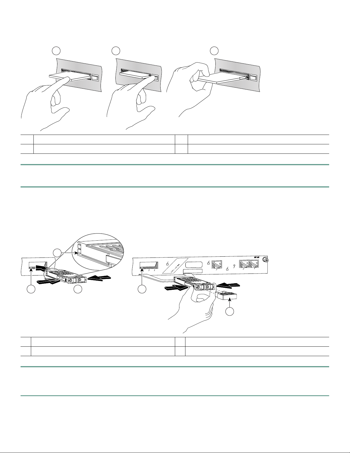
Figure 1 Installing a CompactFlash Disk
1 3
ORK PROCESSING ENGINE - G1
C
O
M
P
A
C
T
FL
AS
H
2
ORK PROCESSING ENGINE - G1
C
O
M
P
A
C
T
FLA
S
H
ORK PROCESSING ENGINE - G1
C
O
M
P
A
C
T
FL
AS
H
66776
1 Inserting the CompactFlash Disk 3 Removing the CompactFlash Disk
2 Releasing the CompactFlash Disk
Step 1 Turn the CompactFlash Disk so that the label is facing down. It is keyed and cannot be inserted incorrectly.
Step 2 Slide the CompactFlash Disk into the CompactFlash Disk slot.
See the Network Processing Engine and Network Services Engine Installation and Configuration document for more
information about using the NPE-G1 or NPE-G2.
Figure 2 Installing the GBIC in an NPE-G1
2
3 3
1
D
1
L
E
E
LINK
S
LE
D
1
T
T
LA
E
N
C
S
C
A
U
S
E
Y
D
A
O
D
L
O
V
D
R
K
C
P
E
IT
LE
1
D
V
O
E
M
A
T
T
S
LE
C
K
S
IT
1
U
A
U
U
L
S
D
D
D
S
O
O
C
O
A
R
E
R
R
L
TX
RX
GE 0
P
C
P
P
D
ETHERNET GIGABIT ETHERNET INPUT/OUTPUT CONTROLLER
LINK
E 0
IO PW
R
OK
CPU
AUX
RESET
CONSOLE
57017
4
GBIC
1
Alignment groove
2
3
4
GBIC slot
Plug
Step 1 Insert the Gigabit Ehternet Gigabit Interface Converter (GBIC) in a GBIC slot on the NPE-G1. The GBIC is keyed so
that it can only be inserted correctly.
Step 2 Repeat Step 1 until the GBICs you ordered are installed.
8
Page 9
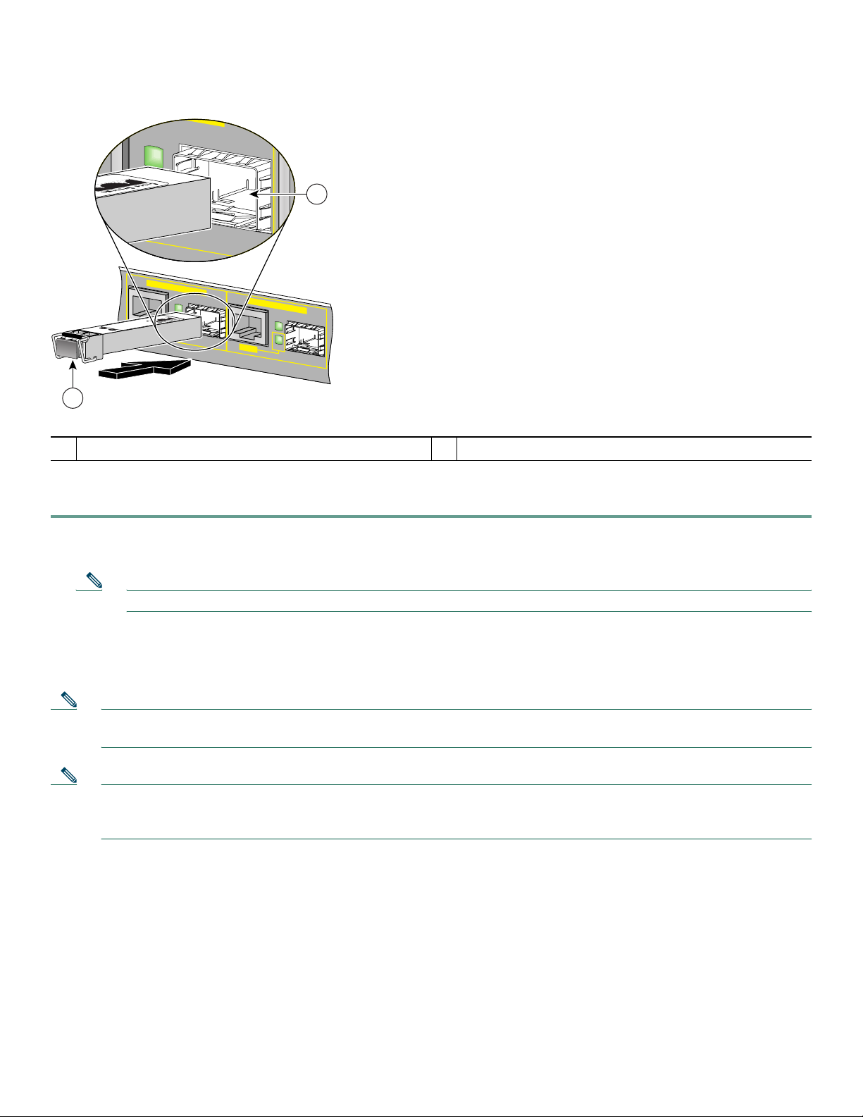
Figure 3 Inserting an SFP Module into the NPE-G2 Gigabit Ethernet Port 0/1
LINK
ACTV
EN
GIGABIT ETHERNET 0 / 1
LINK
ACTV
TX
RX
RJ45
EN
GIGABIT ETHERNET 0 / 2
LINK
ACTV
EN
RJ45
149065
2
1
SFP port 0/1
1
SFP module
2
Use the following procedure to install an SFP module in the NPE-G2:
Step 1 Attach an ESD-preventive wrist strap between you and an unpainted chassis surface.
Step 2 Locate the label on the SFP module and turn the SFP module so the label is on top and the alignment groove is down.
Note The SFP module is keyed so that it cannot be inserted incorrectly.
Step 3 Insert the SFP module into SFP port 0/1, 0/2, or 0/3. The SFP module snaps into place when you have completely and
properly inserted it.
Step 4 Repeat Step 2 if you are inserting a second or third SFP module.
Note Do not remove the plug from the SFP module optical bores until you are ready to install the network interface optical
fiber cable. Save the plug for future use.
Note We strongly recommend cleaning all optical fiber connections before connecting optical cables to equipment. For
information about cleaning optical connectors, see the Inspection and Cleaning Procedures for Fiber-Optic
Connections document and the Compressed Air Cleaning Issues for Fiber-Optic Connections document.
See the Cisco 7200 VXR Installation and Configuration Guide for more information.
9
Page 10
3 Rack-Mount the Router
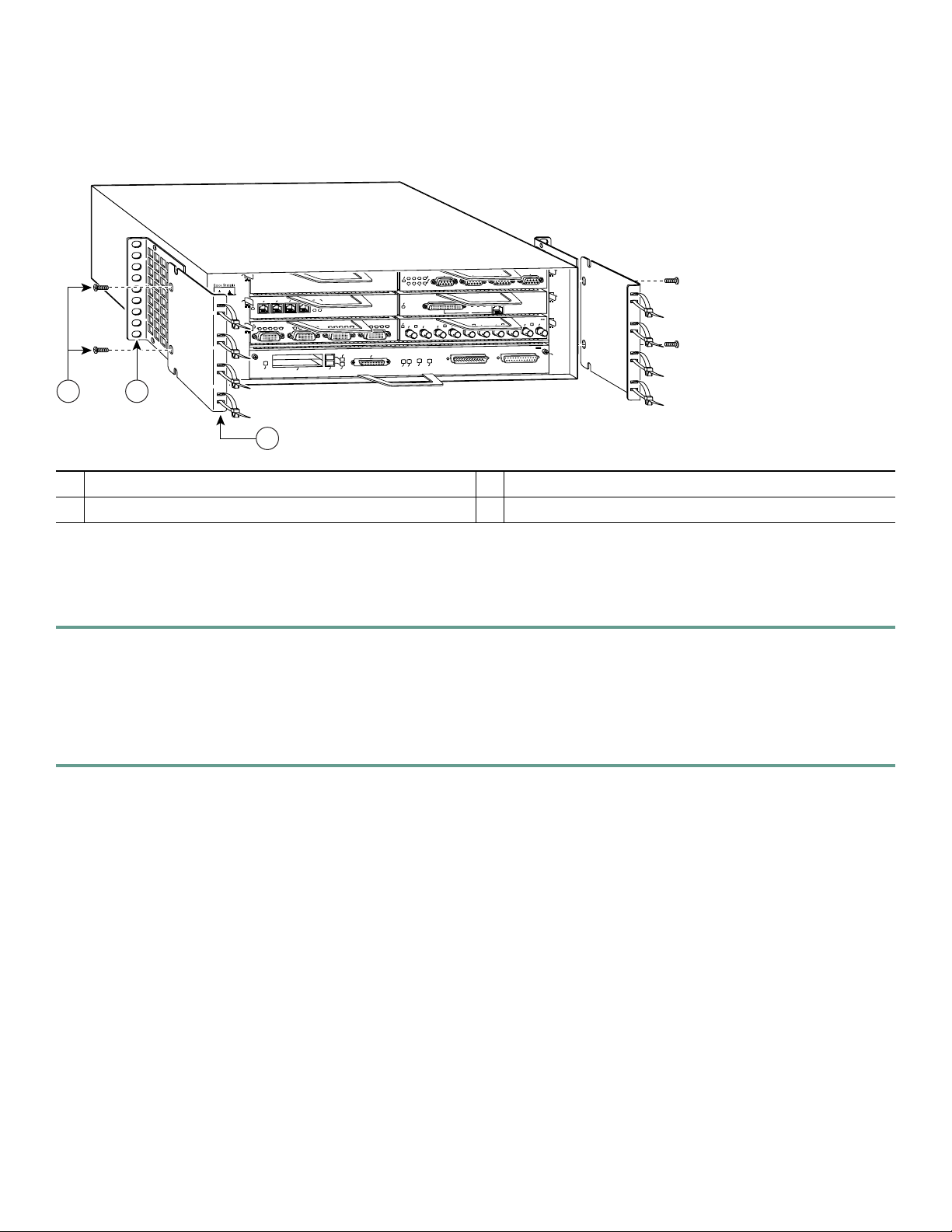
Figure 4 Attaching the Rack-Mount Brackets to the Front of the Chassis
G
IN
R
EN
K
O
G
D
IN
BLE
s
-R
1
0
A
bp
IN
N
5
K
3
D
2
1
0
E
L
B
A
3
N
E
N
E
D
C
D
R
T
T
1
Cisco 7200
Series
ENABLED
3
1
IN
L
3
1
2
0
D
C
B
D
C
D
D
C
B
D
C
D
D
C
R
T
T
C
LB
R
PCMCIA
C
L
R
R
T
T
C
L
R
SLOT 1
EJECT
SLOT 0
E
4/16 M
10BT
ET
N
ER
TH
E
ENABLED
L
AST SERIA
F
D
EN
B
C
C
D
L
C
D
R
R
T
T
FE MII
TX
RX
0
FE
FE LINK
ENABLE
OK
CPU RESET
1O POWER
RX
1
II
M
0
RX
TX
2
FAST ETHERNET INPUT/OUTPUT CONTROLLER
IN
L
T
3
2
T
E
N
R
E
H
T
E
T
S
A
F
5
K
4
J
R
ETHERNET-10BFL
TX
RX
TX
RX
TX
4
3
6
4
2
0
Rack-mount bracket
1
Cable-management bracket
2
2
M4 x 8-mm Phillips flathead screws
3
53498
Brackets Front-Mounted—Chassis Protrudes from the Rack
Locate the rack-mount and cable-management brackets and screws and a Number 2 Phillips screwdriver.
Step 1 Align the rack-mount bracket (1)—as shown above—to the side of the router. Insert and tighten the screws (3) if you
are not adding the cable-management brackets. Repeat this step on the other side of the router.
Go to the “Two-Post or Four-Post Rack Installation” section on page 16.
Step 2 If you are using the cable-management brackets, align the rack-mount bracket (1) to the side of the router, align the
cable-management bracket (2) over the rack-mount bracket—as shown above—and insert the screws (3) through both.
Tighten the screws. Repeat this step on the other side of the router.
If you have an NPE-G1 or NPE-G2 installed, go to the “NPE-G1 and NPE-G2 Rear Cable-Management Brackets on a
Front-Mounted Router” section on page 12.
If you do not have an NPE-G1 or NPE-G2 installed, go to the “Two-Post or Four-Post Rack Installation” section on page 16.
10
Page 11
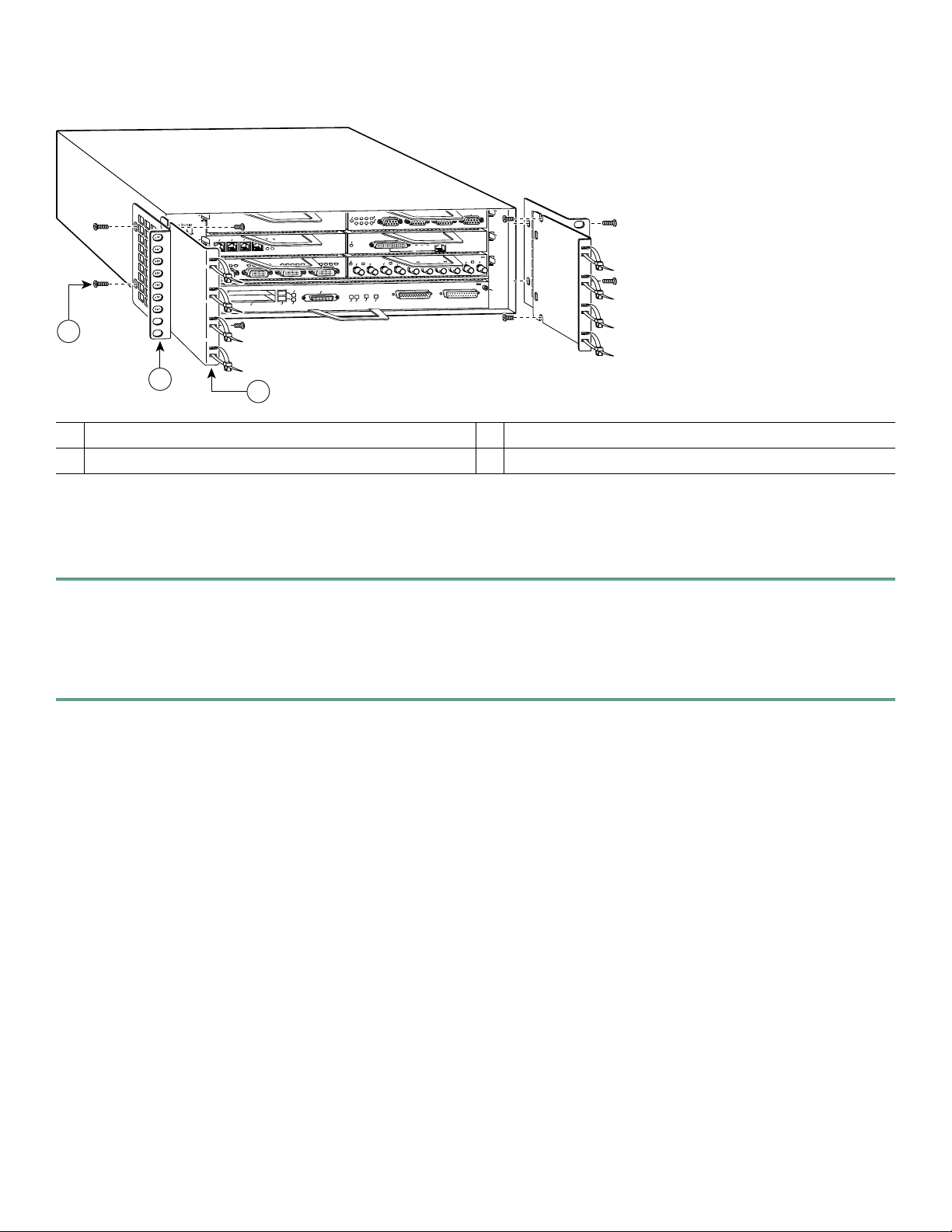
Figure 5 Attaching the Rack-Mount Brackets to the Front of the Chassis—Chassis Recessed
TOKEN RING
3
6
T
E
N
R
E
H
T
E
T
S
A
F
4
L
0BF
NET-1
ETHER
X
X
X
T
R
T
2
4
0
Cisco 7200
Series
5
K
3
D
2
N
1
0
E
L
B
A
3
N
E
N
EN
E
C
D
T
T
1
ENABLED
I
L
3
1
2
0
D
C
B
D
C
D
D
C
B
C
D
L
R
C
R
D
D
C
B
D
C
L
R
R
T
T
C
L
R
R
T
T
SLOT 1
EJECT
SLOT 0
PCMCIA
ENABLED
4/16 Mbps
D
ETHERNET 10BT
E
L
B
A
N
E
L
IA
R
E
S
T
S
FA
N
D
E
B
C
C
D
L
C
D
R
R
T
T
FE MII
X
X
T
R
0
FE
FE LINK
ENABLE
OK
CPU RESET
1O POWER
K
J45
II
IN
R
L
M
0
X
X
X
X
X
R
1
R
T
R
T
2
FAST ETHERNET INPUT/O
3
UTPUT CONTROLLER
2
1
0
IN-RING
3
2
Cable-management bracket
1
Rack-mount bracket
2
1
M4 x 8-mm Phillips flathead screws
3
53499
Brackets Front-Mounted—Chassis Recessed in Rack
Locate the rack-mount and cable-management brackets and screws and a Number 2 Phillips screwdriver.
Step 1 Align the cable-management bracket (1) to the side of the router. Align the rack-mount bracket over it—as shown
above—and insert and tighten the screws (3).
Go to the “Two-Post or Four-Post Rack Installation” section on page 16.
Step 2 If you are not using the cable-management brackets, align the rack-mount brackets (2)—as shown above—to the router
and insert and tighten the screws.
If you have an NPE-G1 or NPE-G2 installed, go to the “NPE-G1 and NPE-G2 Rear Cable-Management Brackets on a
Front-Mounted Router” section on page 12.
If you do not have an NPE-G1 or NPE-G2 installed, go to the “Two-Post or Four-Post Rack Installation” section on page 16.
11
Page 12
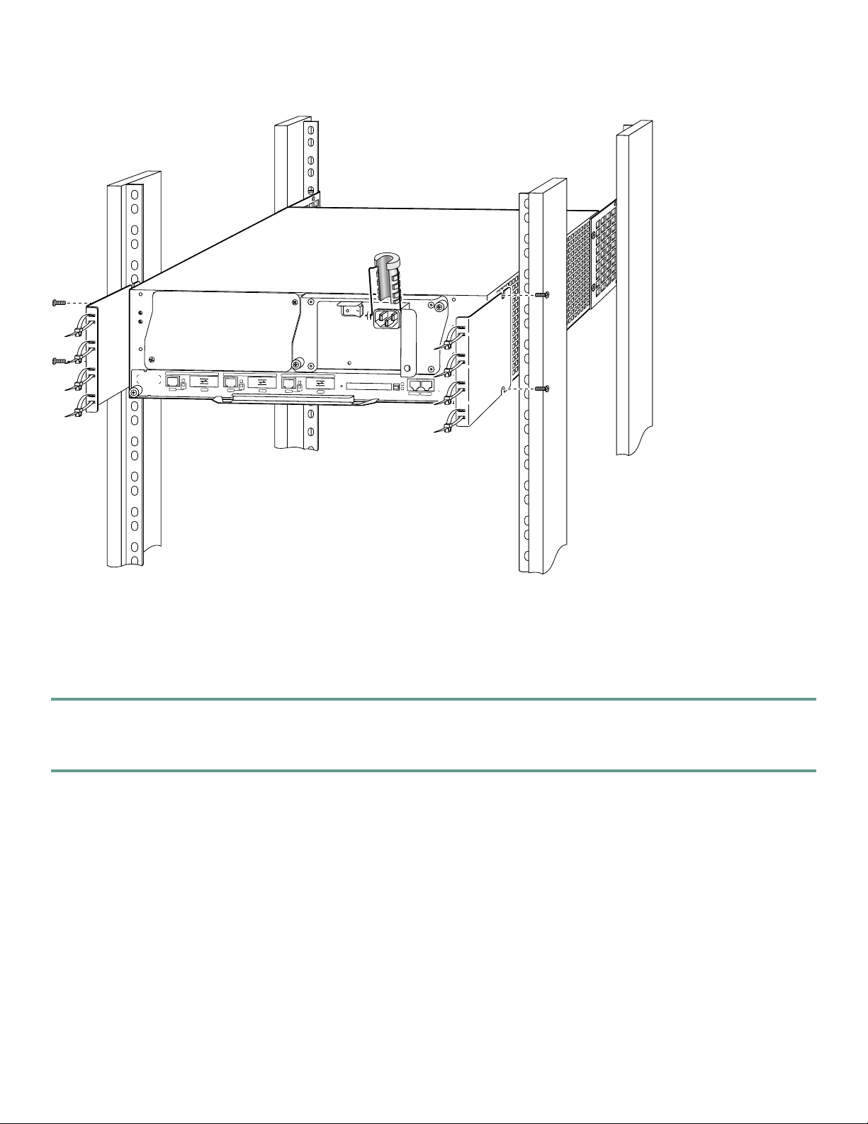
Figure 6 Installing the Rear Cable-Management Brackets with an NPE-G1 or NPE-G2 Installed—Router Front-Mounted
H6423
GIGABIT ETHERNET 0/1
L
IN
K
E
N
R
J
4
5
GIGABIT ETHERNET 0/1
L
I
N
K
E
R
X
N
G
B
I
C
T
X
R
J
4
5
R
GIGABIT ETHERNET 0/1
X
G
B
IC
T
X
R
J
4
5
N
E
TW
O
R
K PR
OC
E
SS
IN
G
EN
G
IN
E - G
1
S
L
O
L
IN
K
C
P
U
R
E
S
E
E
N
T
R
X
G
B
IC
T
X
T
A
C
T
IV
E
P
O
W
E
C
R
O
M
P
A
C
T
F
L
A
S
H
C
O
N
S
O
L
E
O
K
A
U
X
84399
NPE-G1 and NPE-G2 Rear Cable-Management Brackets on a Front-Mounted Router
If you have an NPE-G1 or NPE-G2 installed, install cable-management brackets on the rear of the router as well as on the front
of the router.
Step 1 If the back of the router protrudes from the rack, place the cable-management brackets against the router as shown in
Figure 6.
Step 2 Insert two screws into each bracket, and tighten them to the router.
Go to the “Two-Post or Four-Post Rack Installation” section on page 16.
12
Page 13
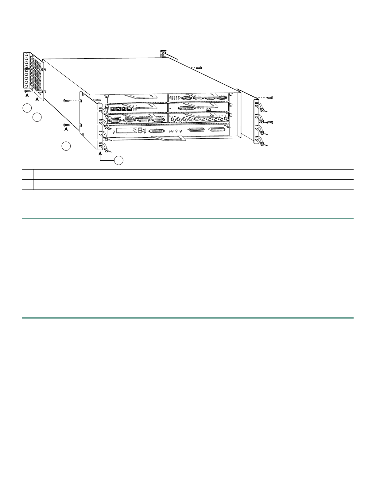
Figure 7 Attaching the Rack-Mount Brackets to the Rear of the Chassis—Front Protrudes from the Rack
TOKEN RING
3
FAST ETHERNET
ETHERN
X
R
6
4
ET-10BFL
X
T
2
4
0
5
K
D
E
L
B
A
3
N
Cisco 7200
Series
E
N
E
D
T
1
ENABLED
2
1
3
2
1
0
D
C
R
T
IN
L
3
1
2
0
D
C
B
D
C
D
D
C
B
D
C
D
D
C
B
R
T
T
C
L
R
PCMCIA
C
L
R
R
T
T
C
L
R
SLOT 1
EJECT
SLOT 0
ENABLED
4/16 Mbps
D
ETHERNET 10BT
E
L
B
A
N
E
FAST SERIAL
N
D
E
B
C
C
D
L
C
D
R
R
T
T
FE MII
X
X
X
R
T
R
0
FE
FE LINK
ENABLE
OK
CPU RESET
1O POWER
X
T
1
RJ45
LINK
MII
0
X
X
X
R
T
R
3
2
FAST ETHERNET INPUT/OUTPUT CONTROLLER
X
T
2
1
0
IN-RING
4
Rack-mount bracket
1
M4 x 8-mm Phillips flathead screws
2
3
Cable-management bracket
3
M4 x 8-mm Phillips flathead screws
4
53500
Brackets Rear-Mounted—Front Protrudes from the Rack
Step 1 Locate the threaded screw holes in the rear sides of the chassis.
Step 2 Align a rack-mount bracket (1) to the threaded holes in the right side of the chassis.
Step 3 Using a Number 2 Phillips screwdriver and two M4 x 8-mm Phillips flathead screws (2), attach the rack-mount bracket
to the router.
Step 4 Repeat Steps 2 and 3 for the bracket on the other side of the router. If you are not installing cable-management brackets,
skip to the “Two-Post or Four-Post Rack Installation” section on page 16 for rack-mount instructions. Otherwise,
continue with Step 5.
Step 5 Align a cable-management bracket (3) to the threaded holes in the front of the chassis.
Step 6 Using two M4 x 8-mm Phillips flathead screws (4), thread and tighten the screws through the cable-management
bracket and into the chassis.
Step 7 Repeat Step 5 and Step 6 on the other side of the router.
If you have an NPE-G1 or NPE-G2 installed, go to the “NPE-G1 or NPE-G2 Rear Cable-Management Brackets on a
Rear-Mounted Router” section on page 15, or the “NPE-G1 or NPE-G2 Optical Cable-Management Bracket” section on
page 16.
If you do not have an NPE-G1 or NPE-G2 installed, go to the “Two-Post or Four-Post Rack Installation” section on page 16.
13
Page 14
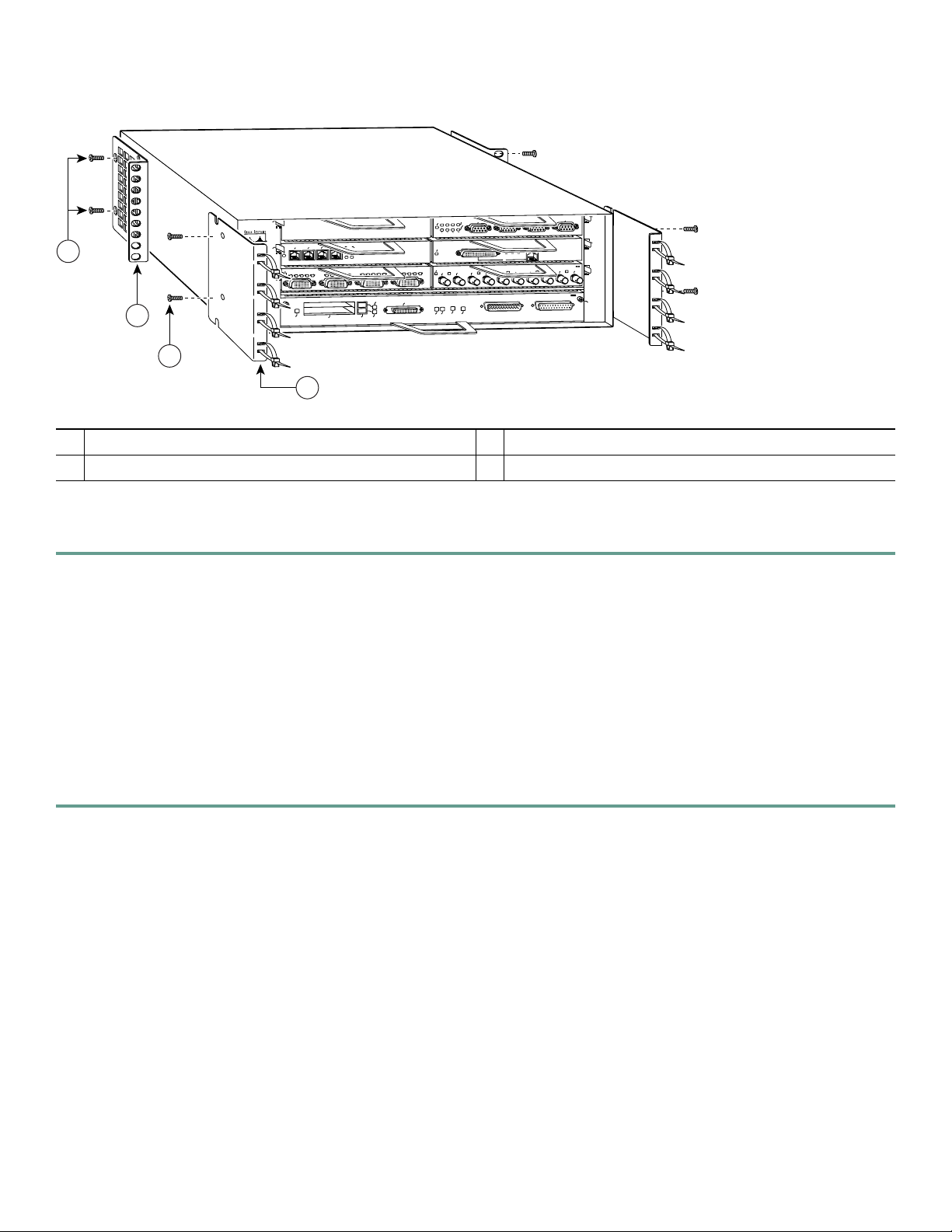
Figure 8 Attaching the Rack-Mount Brackets to the Rear of the Chassis—Front Recessed
G
N RIN
OKE
G
D
IN
BLE
-R
1
0
A
bps
IN
N
5
K
D
E
L
B
A
3
N
Cisco 7200
Series
E
N
E
TD
1
ENABLED
2
1
3
2
1
0
C
RD
T
IN
L
3
1
2
0
D
D
R
TC
T
CD
LB
RC
PCMCIA
CD
LB
RC
RD
TC
TD
CD
LB
RC
SLOT 1
EJECT
SLOT 0
E
6 M
/1
4
T
T 10B
E
RN
E
H
ET
ENABLED
FAST SERIAL
D
EN
C
LB
RC
RD
TC
TD
FE MII
TX
RX
0
FE
FE LINK
ENABLE
OK
CPU RESET
1O POWER
LINK
MII
0
RX
TX
RX
2
1
T
S
A
F
T
3
2
RJ45
TX
RX
TX
3
PU
T
U
/O
T
PU
IN
T
E
N
R
E
H
ET
6
FAST ETHERNET
4
L
F
B
10
-
T
E
N
R
E
H
T
E
TX
RX
2
4
R
LE
L
O
R
T
N
O
T C
0
4
3
57003
Rack-mount bracket
1
M4 x 8-mm Phillips flathead screws
2
Cable-management bracket
3
M4 x 8-mm Phillips flathead screws
4
Brackets Rear-Mounted—Front Recessed in the Rack
Step 1 Locate the threaded screw holes in the rear sides of the chassis.
Step 2 Align a rack-mount bracket (1) to the threaded holes in the right side of the chassis.
Step 3 Using a Number 2 Phillips screwdriver and two M4 x 8-mm Phillips flathead screws (2), attach the rack-mount bracket
to the router.
Step 4 Repeat Step 2 and Step 3 for the bracket on the other side of the router. If you are not installing cable-management
brackets, skip to the “Two-Post or Four-Post Rack Installation” section on page 16 for rack-mount instructions.
Otherwise continue with Step 5.
Step 5 Align a cable-management bracket (3) to the threaded holes in the front of the chassis.
Step 6 Using two M4 x 8-mm Phillips flathead screws (4), thread and tighten the screws through the cable-management
bracket and into the chassis.
Step 7 Repeat Step 5 and Step 6 on the other side of the router.
If you have an NPE-G1 or NPE-G2 installed, go to the “NPE-G1 or NPE-G2 Rear Cable-Management Brackets on a
Rear-Mounted Router” section on page 15, or the “NPE-G1 or NPE-G2 Optical Cable-Management Bracket” section on
page 16.
If you do not have an NPE-G1 installed, go to the “Two-Post or Four-Post Rack Installation” section on page 16.
14
Page 15
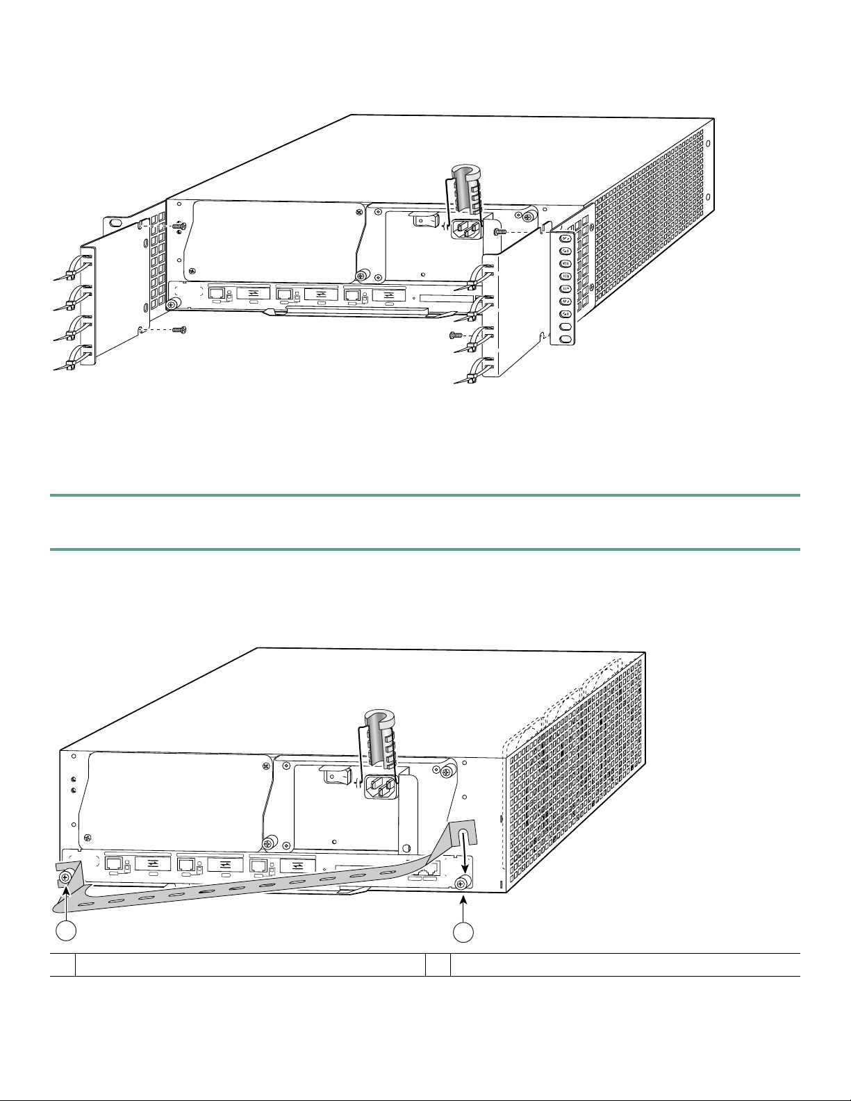
Figure 9 Installing the Rear Cable-Management Brackets with the NPE-G1 or NPE-G2—Router Rear-Mounted
84400
N
E
GIG
ABIT
R
J
4
5
ETHERNET 0/1
L
I
N
K
E
N
R
XT
G
IG
ABIT ET
HERNE
T 0/1
GIG
ABIT ETHE
RNET 0/1
L
IN
K
E
G
B
IC
N
X
R
J
4
5
R
X
G
L
IN
K
E
B
IC
N
T
X
R
J
4
5
R
X
G
B
NETWORK PROCESSING ENGINE - G1
C
P
U
R
E
S
IC
T
X
S
L
O
T
A
C
T
I
V
E
T
C
O
M
P
A
E
P
O
W
E
R
C
T
F
L
A
S
H
C
O
N
S
O
L
E
O
N
A
U
X
NPE-G1 or NPE-G2 Rear Cable-Management Brackets on a Rear-Mounted Router
If you have an NPE-G1 or NPE-G2 installed, install cable-management brackets on the rear of the router as well as on the front
of the router.
Step 1 Align the cable-management brackets with the rack-mount brackets.
Step 2 Insert and tighten two screws for each bracket. The screws come with the cable-management brackets.
Go to the “Two-Post or Four-Post Rack Installation” section on page 16.
Figure 10 Installing the Optical Cable-Management Bracket
80680
G
IGABIT ETHER
NET 0/1
LINK
EN
RJ45
RX
GIG
ABIT ETHERNET 0/1
LINK
GBIC
EN
TX
RJ45
RX TX
GIG
ABIT ETHERNET 0/1
LINK
GBIC
EN
RJ45
RX
GBIC
TX
NETW
ORK PROCESSING ENG
CPU
RESET
NETWORK PROCESSING ENGINE-300
INE - G1
COMPACT FLASH
SLOT
ACTIVE
POWER
C
O
N
S
O
LE
OK
A
U
X
1
Left captive installation screw
1
2
Right captive installation screw
2
15
Page 16

NPE-G1 or NPE-G2 Optical Cable-Management Bracket
Step 1 Loosen the left and right captive installation screws.
Step 2 Hold the cable-management bracket so that it is positioned as shown in Figure 10.
Step 3 Place the left end of the cable-management bracket over the screw.
Step 4 Rotate the cable-management bracket down, until it slides behind the right captive installation screw.
Step 5 Tighten both captive installation screws.
Go to the “Two-Post or Four-Post Rack Installation” section on page 16.
Figure 11 Installing the 7200 VXR in a Two-Post and Four-Post Rack
1
G
IN
R
EN
K
O
T
3
6
2
1
0
IN-RING
5
3
D
2
1
0
E
L
B
A
3
N
Cisco 7200
Series
E
N
E
D
C
D
D
C
B
D
RC
C
R
D
T
T
C
L
R
R
T
T
1
PCMCIA
ENABLED
5
Cisco 7200
Series
G
IN
R
N
E
K
O
T
3
6
X
R
0
1
0
X
X
R
T
2
1
5
K
4
J
II
IN
R
L
M
X
X
R
T
3
2
FAST ETHERNET INPUT/OUTPUT CONTROLLER
FAST ETHERNET
4
L
F
B
0
-1
T
E
N
R
E
H
T
E
X
X
X
T
R
T
2
4
0
-RING
ABLED
bps
IN
5
3
D
2
1
0
INK
E
L
ABL
3
1
3
1
N
E
2
0
EN
TC
TD
ENABLED
TC
D
TD
CD
D
LB
RC
RD
TC
TD
C
LB
RC
R
EJECT
SLOT 0
PCMCIA
EN
4/16 M
D
T
T 10B
NE
ER
ETH
E
L
B
A
N
E
FAST SERIAL
N
E
C
CD
LB
R
RD
TC
X
TD
X
CD
LB
RC
RD
SLOT 1
T
R
0
FE MII
FE
FE LINK
ENABLE
OK
1O POWER
CPU RESET
2
3
6
ENABLED
4/16 Mbps
T
B
10
T
E
N
R
E
H
T
E
K
N
I
L
3
1
2
0
D
B
C
L
LED
ENAB
L
IA
ER
S
ST
FA
N
D
E
B
C
C
D
L
C
D
D
C
B
D
D
R
R
TC
T
SLOT 1
EJECT
SLOT 0
X
R
R
T
X
T
X
C
L
R
T
R
1
0
FE MII
FE
FE LINK
ENABLE
OK
CPU RESET
1O POWER
T
E
N
R
E
H
T
E
T
S
A
F
5
K
4
I
4
N
J
I
I
R
L
M
0
L
F
B
0
1
T
E
N
R
E
H
T
E
X
X
X
X
T
X
X
R
T
X
R
T
R
T
2
4
3
2
R
E
L
L
O
R
T
N
O
C
T
U
P
T
U
/O
T
U
P
IN
T
E
N
R
E
H
T
E
T
S
A
F
0
4
57108
Two-post rack
1
Rack-mount bracket
2
10-32 x 3/8-inch slotted binderhead screws
3
Four-post rack
4
Rack-mount bracket
5
10-32 x 3/8-inch slotted binderhead screws
6
Two-Post or Four-Post Rack Installation
Note Inner clearance (the width between the inner sides of the two posts or rails) must be at least 17.00 inches (43.18 cm).
The height of the chassis is 5.25 inches (13.34 cm).
Step 1 Make sure that all chassis screws holding the network processing engine or network services engine, I/O controller, and
power supply are tightened and that any port adapter levers are in a locked position.
Step 2 Make sure the rack brakes are locked or the rack is stabilized.
Step 3 With the router front closest to you, lift it carefully into the rack. To prevent injury, avoid any sudden twists or moves.
Step 4 Slide the chassis into the rack, until the brackets meet the mounting strips or posts on both sides of the rack.
Step 5 Keeping the brackets flush against the posts or mounting strips, align the holes in the brackets with the holes on the
rack or mounting strip.
Step 6 For each bracket, insert and tighten three 10-32 x 3/8-inch slotted binderhead screws, using the top, bottom, and one
other location on the bracket.
16
Page 17

Figure 12 Installing the Chassis Ground Connection
1
3
2
57006
4
Chassis ground connector
1
Grounding lug
2
NE
3
4
TW
ORK
PRO
CESSING ENGINE-300
Screws
Wire
Install the Chassis Ground
Note The grounding lug and Phillips screws are not available from Cisco Systems. Get the grounding lug from an
electrical-connector vendor and the screws from a hardware vendor. See “Tools and Parts” section on page 6 for the
parts needed.
Step 1 Locate the chassis ground connector (1) on the rear of your router chassis.
Step 2 Insert the two screws (3) through the holes in the grounding lug (2).
Step 3 Ensure that the grounding lug does not interfere with other router hardware, such as power supplies or the network
processing engine (NPE) or network services engine (NSE).
Step 4 Use the Number 2 Phillips screwdriver to carefully tighten the screws until the grounding lug is held firmly to the
chassis. Do not overtighten the screws.
Step 5 Use the wire stripper to strip one end of the 6-AWG wire approximately 0.75 inches (19.05 mm).
Step 6 Insert the 6-AWG wire (4) into the wire receptacle on the grounding lug.
Step 7 Use the crimping tool to carefully crimp the wire receptacle around the wire; this step is required to ensure a proper
mechanical connection.
Step 8 Connect the opposite end of the grounding wire to the appropriate grounding point at your site to ensure an adequate
chassis ground.
17
Page 18

4 Connect the Router to the Network
Figure 13 Connecting the Console and Auxiliary Port Cables
1
FE MII
ENABLED
PCMCIA
Auxiliary port-DTE-mode; EIA/TIA-232, DTE-DB-25
1
SLOT 1
EJECT
SLOT 0
RJ-45
MII
RJ45
RJ45
EN
OK
EN
1O PWR
LINK
CPU RESET
FAST ETHERNET INPUT/OUTPUT CONTROLLER
2
57007
3
3
4
Modem
connector (for modem, CSU/DSU, and so on.)
Console port-DCE-mode; EIA/TIA-232, DCE-DB-25
2
Console terminal
4
connector (for data terminal)
I/O Controller and NPE-G1 or NPE-G2 Console and Auxiliary Port Cable Connections
Note Both the console and auxiliary ports are asynchronous serial ports; any devices connected to these ports must be capable
of asynchronous transmission.
Step 1 Before connecting a terminal to the console port, configure the terminal to match the router console port as follows:
9600 baud, 8 data bits, no parity, 2 stop bits (9600 8N2).
Step 2 Use an EIA/TIA-232 DCE console cable to connect the terminal to the console port. After you establish normal router
operation, you can disconnect the terminal.
Note You must supply your own interface cable between the auxiliary port and the equipment you are connecting.
For console and auxiliary port pinouts, see the online Cisco 7200 VXR Installation and Configuration Guide,
Chapter 3, “Console Port Signals and Auxiliary Port Signals.”
Note When connecting to an auxiliary port on a Cisco 7200 VXR router, the port will not function at baud rates
higher than 19.2kb. If the baud rate on the connecting device is set higher than 19.2kb, garbled text or nothing
will be displayed on the screen.
18
Page 19

Depending on the I/O controller installed in your Cisco 7200 VXR router, you may have a Gigabit Ethernet port, RJ-45 ports,
or no Ethernet port. The following table provides information about the types of ports on different I/O controller models.
Table 2 I/O Controller Port Information
Product Number Description
C7200-I/O-GE+E 1 Gigabit Ethernet and 1 Ethernet port; equipped with a GBIC receptacle for 1000 megabits per
second (Mbps) operation and an RJ-45 receptacle for 10-Mbps operation.
C7200-I/O-2FE/E 2 autosensing Ethernet/Fast Ethernet ports; equipped with 2 RJ-45 receptacles for 10/100-Mbps
operation.
C7200-I/O Has no Ethernet port.
Ethernet Port Connections
I/O controllers have the possibility of one or two of three types of Ethernet connections: MII connections and RJ-45 connections
for 10/100-Mbps operation, and a Gigabit Interface Converter (GBIC) connection for 1000-Mbps operation. For more
information about Ethernet ports, see the online Cisco 7200 VXR Installation and Configuration Guide.
RJ-45 Connections
Warning
To avoid electric shock, do not connect safety extra-low voltage (SELV) circuits to telephone-network voltage
(TNV) circuits. LAN ports contain SELV circuits, and WAN ports contain TNV circuits. Some LAN and WAN ports
both use RJ-45 connectors. Use caution when connecting cables.
Statement 1021
To identify the RJ-45 cable type, hold the two ends of the cable next to each other so you can see the colored wires inside the
ends. The straight-through wire type has colored wires in the same sequence at both ends.
In the crossover wire type, the first colored wire at the far left is the third colored wire at the other end. The second colored
wire at the far left is the sixth colored wire at the other end.
Attach any RJ-45 Ethernet cables to the appropriate connector.
Figure 14 Connecting Optical Fiber Cables
5 6
LINK
PORT
GE 0
TX
PRODUCTO LED DE CLASE 1
CLASS 1 LED PRODUCT
PRODUKT MIT KLASSE 1 LED
PRODUIT AVEC VOYANT DEL
DE CLASSE 1
57010
RX
2
4
1
3
To external 1000BASEX network
1
1 duplex connector (TX and RX)
2
To external 1000BASEX network
3
2 simplex connectors
4
RX
5
TX
6
19
Page 20

SFP and GBIC Interface Cables Installation
For more information on cables, specifications, or product numbers, see the Cisco 7200 VXR Installation and Configuration
Guide or the Network Processing Engine or Network Services Engine Installation and Configuration.
Note All SFPs have LC type connectors. All GBIC ports have SC-type connectors.
After the GBIC or SFP is installed in the Gigabit Ethernet port, you must attach the optical fiber cables to the SFP or GBIC.
Optical fiber cables are commercially available; they are not available from Cisco Systems.
Warning
Warning
Note The 1000BASEZX SFP or GBIC provides an optical power budget of 21.5 dB. Measure your cable plant with an optical
Class 1 laser product.
Because invisible laser radiation may be emitted from the aperture of the port when no cable is connected, avoid
exposure to laser radiation and do not stare into open apertures.
loss test set to verify that the optical loss of the cable plant (including connectors and splices) is less than or equal to
21.5 dB. The optical loss measurement must be performed with a 1550-nm light source.
Statement 1008
Statement 70
Attach the Multimode and Single-Mode Optical Fiber Cables
Note We strongly recommend cleaning all optical fiber connections before reconnecting optical cables to equipment. For
information about cleaning optical connectors, see the Inspection and Cleaning Procedures for Fiber-Optic
Connections document and the Compressed Air Cleaning Issues for Fiber-Optic Connections document.
Attach the appropriate optical fiber cable directly to the LC-type connector on the SFP, or the SC-type receptacle on the GBIC.
You can use either simplex or duplex connectors for most devices.
• Two cables are required for simplex connectors, one cable for transmit (TX) and one for receive (RX).
• One cable that has both TX and RX connectors is required for duplex connectors.
Caution If you plan to use a WS-G5486 or GBIC-LX/LH or SFP-GE-L at distances greater than 984.25 feet (300 meters)
over 50/125-micron or 62.5/125-micron multimode fiber, you must use the mode-conditioning patch cord to
prevent data transmission problems.
Attach the Mode-Conditioning Patch Cord
A mode-conditioning patch cord can be used with GBIC WS-G5486 or GBIC-LX/LH or SFP-GE-L to allow reliable laser
transmission between the single-mode laser source on the GBIC or SFP and a multimode optical fiber cable. To use the
mode-conditioning patch cord, follow these steps:
Step 1 Attach the patch cord. For a GBIC on the NPE-G1, use a patch cord with an SC-type connector. For the SFP on the
NPE-G2, use a patch cord with an LC-type connector.
Step 2 Attach the network ends (beige/beige) of your patch cord to the appropriate 1000BASEX equipment in your building
cable plant.
20
Page 21

Note Ensure that you connect the TX and RX ports on one end of the patch cord to the RX and TX ports (respectively) on
the other end. Connect TX to RX and RX to TX.
Port Adapter Cable Connections
The instructions for connecting the cables for each port adapter installed in the Cisco 7200 VXR routers are in the respective
online note for each port adapter. The documents are available on the Documentation DVD and on Cisco.com. Reference them
from the Cisco 7200 Series Routers Documentation Roadmap at:
http://www.cisco.com/en/US/docs/routers/7200/roadmaps/7200_series_doc_roadmap/3512.html
Placing the Cables in the Cable-Management Brackets
Figure 15 Placing Cables in the Cable-Management Brackets
H6423
GIGABIT ETHERNET 0/1
L
IN
K
E
N
R
J
4
5
GIGABIT ETHERNET 0/1
L
IN
K
E
R
X
N
G
B
IC
T
X
R
J
4
5
R
GIGABIT ETHERNET 0/1
X
G
B
IC
T
X
R
J
4
5
N
E
TW
O
R
K
P
R
O
C
E
S
S
IN
G
E
N
G
IN
E
- G
1
S
L
O
L
IN
K
C
P
U
R
E
S
E
E
N
T
R
X
G
B
IC
T
X
T
A
C
T
IV
E
P
O
W
E
C
R
O
M
P
A
C
T
F
L
A
S
H
C
O
N
S
O
L
E
O
K
A
U
X
84399
Step 1 Place the GBIC cables, RJ-45 cables, or SFP cables through the NPE-G1 or NPE-G2 optical cable-management brackets.
Step 2 Place any cables from port adatpers, auxiliary and console ports, through the cable mangement brackets and secure.
21
Page 22

5 Start and Configure the Router
Power Cable Connections
Caution This unit might have more than one power cord. To reduce the risk of electric shock, disconnect the two power
supply cords before servicing the unit. Statement 83
Warning
The AC power supply has double pole/neutral fusing.
Statement 188
Connect AC-Input Power
Note When powering off the router, wait a minimum of 30 seconds before powering it on again.
Figure 16 Connecting the AC Power Cable
1
84398
2
3
54
Power switch
1
AC power cable
2
PWR OK LED
3
Step 1 At the rear of the router, check that the power switch (1) is in the off (O) position.
Step 2 Slide the cable-retention clip (4) up, away from the AC port, and plug in the power cable (2).
Step 3 If you are installing the adjustable power cable-retention clip shown in Figure 16, follow these steps:
a. Remove the retention-clip wire and replace it with the new cable-retention clip wire.
b. Insert the plastic portion of the clip, and adjust it to the desired length.
Step 4 Secure the cable in the power supply AC port by sliding the cable-retention clip down until it fits around the connector.
The cable-retention clip provides strain relief for the AC power cable.
Step 5 If you require additional AC power cable strain relief, secure the cable to the power supply handle by inserting a nylon
cable tie through the hole (5) in the handle and around the cable.
22
AC power cable-retention clip
4
Hole for nylon cable tie
5
Page 23

Step 6 Plug the AC power supply cable into the AC power source. Repeat Step 1 through Step 6 for the second power supply
(if present).
Connect DC-Input Power
Note The color coding of the DC-input power supply leads depends on the color coding of the DC power source at your
site. Typically, green or green/yellow is used for ground. Make certain the lead color coding you choose for the
DC-input power supply matches lead color coding used at the DC power source.
Warning
Caution The DC return connection to this system is to remain isolated from the system frame and chassis (DC-I).
Figure 17 Attaching the DC Power Cables
When you install the unit, the ground connection must always be made first and disconnected last.
Statement 42
4
57013
1
3
2
Ground lead service loop
1
DC power leads
2
Step 1 At the rear of the router, check that the power switch is in the off (O) position.
Step 2 Ensure that the –V and +V leads are disconnected from the power source.
Step 3 Using a wire stripper, strip approximately 0.55 inch (14 mm) from the –V, +V, and ground leads (2).
Step 4 Insert the stripped end of the ground lead (1) all the way into the ground lead receptacle on the DC-input power supply,
and tighten the receptacle screw using a 3/16-inch flat-blade screwdriver.
Step 5 Insert the stripped end of the +V lead all the way into the +V lead receptacle and tighten the receptacle screw using the
same 3/16-inch flat-blade screwdriver. Repeat this step for the –V lead.
Cable tie
3
Power switch
4
23
Page 24

Note Make sure the entire stripped end of each lead is inserted all the way into its receptacle. If any exposed wire at
the stripped end of a lead is visible after inserting the lead into its receptacle, remove the lead from the
receptacle, use the wire stripper to cut the stripped end of the lead, and repeat Step 3 through Step 5.
Step 6 Use a cable tie to secure the leads to the power supply.
When securing the ground, +V, and –V DC-input leads to the power supply faceplate, leave a small service loop in the
ground lead to ensure that the ground lead is the last lead to disconnect from the power supply if a great deal of strain
is placed on all three leads.
Step 7 Connect the ground, +V, and –V leads to the power source.
Important NPE-G1 and NPE-G2 Information
Following is some important NPE-G1 information that you need to know before you power on the router:
• The NPE-G2 has its own Cisco IOS software image with the prefix “c7200p-” in the software images file names, including
the boot image. The NPE-G2 does not boot up with a software image with the prefix “c7200-”. Previous network processing
engines, or the network services engine, do not boot up with the “c7200p-” boot image. They use the prefix “c7200-”.
The RJ-45 ports and GBIC ports or SFP ports are both reported in software as GigabitEthernet 0/1, GigabitEthernet 0/2, and
•
GigabitEthernet 0/3. Only one of the pair of interface ports can be used at a time, for example, GE 0/2 or RJ-45 0/2.
• The I/O controller GE/E interface reports GE 0/0, and the I/O controller 2FE/E interface reports FE 0/0.
• If the RJ-45 port is in use, the EN (enabled) LED is on. If the GBIC or SFP is in use, the EN (enabled) LED is off.
• With the NPE-G1 or NPE-G2 and an I/O controller both installed, the I/O controller functionality on the NPE-G1 or NPE-G2
is shared with that of the I/O controller.
• The console and auxiliary ports on the NPE-G1 or NPE-G2 are disabled by Cisco IOS when an I/O controller is present; the
console and auxiliary ports on the I/O controller are active.
• Console port messages can be routed to the auxiliary port on either the NPE-G1 or NPE-G2 or on the I/O controller.
• The default media is the RJ-45 port. To change the media type, use the media-type command.
• Only the port selected by the media-type command is active. A cable attached to the other of the RJ-45 and GBIC or SFP pair
will be ignored. For example, if GBIC GigabitEthernet 0/2 is selected using the media-type command, RJ-45 GigabitEthernet
0/2 is ignored, even if a cable is attached to GBIC GigabitEthernet 0/2.
• The NPE-G1 or NPE-G2 uses no bandwidth points. If The NPE-G1 or NPE-G2 is in the router with an I/O controller, the I/O
controller also uses no bandwidth points. None of the Gigabit Ethernet interfaces on the NPE-G1 or NPE-G2 use bandwidth
points.
• The CompactFlash Disk on the NPE-G1 or NPE-G2 is available at all times, with or without an I/O controller installed.
• The USB ports on the NPE-G2 are available at all times, with our without an I/O controller installed.
Note The Gigabit Ethernet interfaces on the NPE-G1 or NPE-G2 do not support the Inter-Switch Link (ISL) VLAN
encapsulation protocol. We recommend that you use the IEEE 802.1Q VLAN encapsulation protocol as an alternative.
Where an application requires the use of ISL, this can be provided by the Fast Ethernet or Gigabit Ethernet port adapters
or I/O controllers.
24
Page 25

Start the System and Perform a Basic Configuration
Step 1 Check that all hardware parts and cables are securely attached to the chassis.
Step 2 Check that a CompactFlash Disk, Flash Disk, or PC Card or Flash memory card is installed.
Step 3 Check that the console terminal is turned on.
Caution If you have just installed an NPE-G1 or NPE-G2 in place of an older NPE, you must save your configuration to a
Flash Disk, PC Card, Flash memory card, or TFTP server before you power on the router with the new NPE-G1 or
NPE-G2 installed, or you will lose your configuration.
file, see the onlin
e Network Processing Engine and Network Services Engine Installation and Configuration
document, Chapter 6, “Copying the Configuration File.”
Step 4 Place the power switch in the on (|) position. Repeat this action if there is a second power supply.
Note When powering on the router, wait a minimum of 30 seconds before powering it off again.
Step 5 Listen for the fans; they should be operating as soon as power is turned on.
Step 6 During the boot process, observe the system LEDs. The power LED on the I/O controller comes on immediately. Port
adapter LEDs go on and off irregularly.
Step 7 Observe the initialization process. The LEDs on each port adapter behave differently (most flash on and off). The
ENABLED LED on each port adapter goes on when initialization is completed and the console screen displays a script
and system banner.
For instructions on copying and saving your configuration
Note For more information on LEDs, refer to the “LED Description” section in Chapter 1 of the Cisco7200VXR
Installation and Configuration Guide.
Before configuring the router, determine whether or not you want to use a management tool such as Cisco Security Device
Manager.
Cisco Security Device Manager (SDM), version 1.1, is an optional Java-based device-management tool that allows you to
configure LAN interfaces, routing, Network Address Translation (NAT), firewalls, Virtual Private Networks (VPNs), and other
features without knowledge of the Cisco command-line interface (CLI). You can configure features such as Access Control Lists
(ACLs), routing protocols, and other options using SDMs advanced mode.
Note You will need to use CLI commands to configure several features that SDM does not support. SDM does not support
the following features: WAN configuration, Gigabit Ethernet (GE) interfaces, AA client, EZ VPN server, QoS,SSHv2,
DHCP server configuration options, and usability enhancements.
SDM is preinstalled on your routers Flash Disk or CompactFlash Disk when it is ordered as part of a VPN bundle or as part of
a 7xxx VPN bundle. If your router did not ship with SDM preinstalled, you can download a free copy from the Software Center
at Cisco.com at http://ww.cisco.com/kobayashi/sw-center/index.shtm. Because SDM uses a GUI, it requires that you access it
from a PC using a supported web browser. Go to the Cisco Router and Security Device Manager (SDM) User Guide for the
Cisco 7200 VXR and Cisco 7301 Routers for more information.
Configure the Router
When you start up the router for the first time, the system automatically enters the setup facility, which determines which port
adapters are installed and prompts you for configuration information for each one. On the console terminal, after the system
displays the system banner and hardware configuration, you will see the following System Configuration Dialog prompt:
--- System Configuration Dialog ---
25
Page 26

At any point you may enter a questions mark ‘?’ for help.
Use ctrl-c to abort configuration dialog at any prompt.
Default settings are in square brackets ‘[]’.
continue with configuration dialog? [yes]:
Step 1 Enter yes or press Return to enter the initial configuration dialog.
You have the option of proceeding with the setup facility to configure the interfaces, or exiting from setup and using
configuration commands to configure global (system-wide) and interface-specific parameters. You do not have to
configure the interfaces immediately; however, you cannot enable the interfaces or connect them to any networks until
you have configured them.
Many of the port adapter LEDs do not go on until you have configured the interfaces. To verify correct operation of
each interface, complete the first-time startup procedures and configuration, and then refer to the configuration note
for each port adapter for LED descriptions and to check the status of the interfaces.
If the system does not complete each of the steps in the startup procedure, refer to the online Cisco 7200 VXR
Installation and Configuration Guide, Appendix A, “Troubleshooting the Installation,” for troubleshooting
recommendations and procedures.
Note You need to acquire the correct network addresses from your system administrator or consult your network
plan to determine correct addresses before you can complete the router configuration.
Perform a Basic Configuration Using the Setup Facility
If you do not plan to use AutoInstall, do not connect the router’s serial (WAN) cable to the channel service unit/data service unit
(CSU/DSU). If the WAN cable is not connected, the router boots from Flash memory and goes automatically into the setup
facility.
Note You can run the setup facility any time you are at the enable prompt (#) by entering the setup command.
If the serial (WAN) cable is connected to the CSU/DSU and the router does not have a configuration stored in NVRAM, the
router attempts to run AutoInstall at startup. The router may take several minutes to determine that AutoInstall is not set up
to a remote TCP/IP host. Once the router determines that AutoInstall is not configured, it defaults to the setup facility.
Configure Global Parameters
When you first start the setup program, you must configure the global parameters. These parameters are used for controlling
system-wide settings. Complete the following steps to enter the global parameters:
Step 1 Connect a console terminal to the console port on the I/O controller, NPE-G1, or NPE-G2.
Step 2 Power on the router.
The system boots from Flash memory. After startup, the console screen displays a script and a system banner—after
about 30 seconds—similar to the following. When you see this information, you have successfully booted your router:
Restricted Rights Legend
Use, duplication, or disclosure by the Government is
subject to restrictions as set forth in subparagraph
(c) of the Commercial Computer Software - Restricted
Rights clause at FAR sec. 52.227-19 and subparagraph
(c) (1) (ii) of the Rights in Technical Data and Computer
Software clause at DFARS sec. 252.227-7013.
26
Page 27

cisco Systems, Inc.
170 West Tasman Drive
San Jose, California 95134-1706
Cisco Internetwork Operating System Software
IOS (tm) 7200 Software (C7200-JS-M), Released Version 12.0(19980705:021501)Copyright(c) 1986-1998 by
cisco Systems, Inc.
Compiled Thu 15-Oct-98 02:20 by xxxxx
Image text-base: 0x600088C4, data-base: 0x60FA6000
cisco 7206VXR (NPE300) processor with 61440K/20480K bytes of memory.
R7000 CPU at 262Mhz, Implementation 39, Rev 1.0, 256KB L2, 2048KB L3 Cache
Six slot VXR midplane, Version 2.0
Last reset from power-on
Bridging software.
X.25 software, Version 3.0.0.
SuperLAT software (copyright 1990 by Meridian Technology Corp).
TN3270 Emulation software.
8 Ethernet/IEEE 802.3 interface(s)
3 FastEthernet/IEEE 802.3 interface(s)
125K bytes of non-volatile configuration memory.
20480K bytes of Flash PCMCIA card at slot 0 (Sector size 128K).
8192K bytes of Flash PCMCIA card at slot 1 (Sector size 128K).
4096K bytes of Flash internal SIMM (Sector size 256K).!!
Press RETURN to get started!
The first two sections of the configuration script (the banner and the installed hardware) appear only at initial system
startup. On subsequent uses of the setup facility, the script begins with a System Configuration Dialog as shown in the
following example:
--- System Configuration Dialog ---
At any point you may enter a question mark '?' for help.
Use ctrl-c to abort configuration dialog at any prompt.
Default settings are in square brackets '[]'.
Step 3 When asked if you want to enter the initial configuration dialog and see the current interface summary, enter yes or
press Return:
Would you like to enter the initial configuration dialog? [yes]:
First, would you like to see the current interface summary? [yes]:
In the following example, the summary shows a Cisco 7200 VXR router at first-time startup; that is, nothing is
configured:
Any interface listed with OK? value "NO" does not have a valid configuration
Interface IP-Address OK? Method Status Protocol
ATM1/0 unassigned NO unset down down
FastEthernet2/0 unassigned NO unset down down
Step 4 Choose which protocols to support on your interfaces. For Internet Protocol (IP)-only installations, you can accept the
default values for most of the questions. A typical configuration using IP, IPX, and AppleTalk follows and continues
through Step 9:
Configuring global parameters:
Enter host name [Router]:
Step 5 Enter enable secret, enable, and virtual terminal passwords:
The enable secret password is a one-way cryptographic secret password used instead of the enable password
when it exists.
27
Page 28

Enter enable secret: barney
The enable password is used when there is no enable secret password and when using older software and
some boot images.
Enter enable password: betty
Enter virtual terminal password: fred
Step 6 The Simple Network Management Protocol (SNMP) is the most widely supported open standard for network
management. It provides a means to access and set configuration and run-time parameters of routers and
communication servers. SNMP defines a set of functions that can be used to monitor and control network elements.
Enter yes or press Return to accept SNMP management; enter no to refuse it:
Configure SNMP Network Management? [yes]:
Community string [public]:
Step 7 For the following queries, do not enable VINES, LAT, DECnet, CLNS, bridging, XNS, or Apollo:
Configure Vines? [no]:
Configure LAT? [no]:
Configure DECnet? [no]:
Configure CLNS? [no]:
Configure bridging? [no]:
Configure XNS? [no]:
Configure Apollo? [no]:
Step 8 For the following queries, enable routing on AppleTalk and IPX:
Configure AppleTalk? [no]: yes
Multizone networks? [no]: yes
Configure IPX? [no]: yes
Step 9 In most cases, you use IP routing. If you are using IP routing, you must also select an interior routing protocol. You can
specify only one of two interior routing protocols to operate on your system using the setup facility: Interior Gateway
Routing Protocol (IGRP) or Routing Information Protocol (RIP). To configure IP routing, enter yes (the default) or press
Return, and then select an interior routing protocol:
Configure IP? [yes]:
Configure IGRP routing? [yes]:
Your IGRP autonomous system number [1]:
The following sample display includes a continuous listing of all configuration parameters selected in Step 4 through
Step 9. Only IP, IPX, and AppleTalk are the selected protocols for this example.
Configuring global parameters:
Enter host name [Router]: router
The enable secret is a one-way cryptographic secret used instead of the enable password when it exists.
Enter enable secret: barney
The enable password is used when there is no enable secret and when using older software and some boot
images.
Enter enable password: betty
Enter virtual terminal password: fred
Configure SNMP Network Management? [yes]:
Community string [public]:
Configure Vines? [no]:
Configure LAT? [no]:
Configure AppleTalk? [no]: yes
Multizone networks? [no]: yes
Configure DECnet? [no]:
Configure IP? [yes]:
28
Page 29

Configure IGRP routing? [yes]:
Your IGRP autonomous system number [1]: 15
Configure RIP routing? [no]:
Configure CLNS? [no]: n
Configure bridging? [no]:
Configure IPX? [no]: yes
Configure XNS? [no]:
Configure Apollo? [no]:
Step 10 Save your settings to NVRAM. (See the “Save the Running Configuration to NVRAM” section on page 34.) Save the
configuration settings that you created in the router using the configuration mode and the setup facility. If you fail to
do this, your configuration will be lost the next time you reload the router.
Configuration Information for the NPE-G1 or NPE-G2
If the NPE-G1 or NPE-G2 and an I/O controller are both installed in the same system, the console and auxiliary ports on the
I/O controller are used and the console and auxiliary ports on the NPE-G1 or NPE-G2 are disabled by Cisco IOS.
Note Both the NPE-G1 or NPE-G2 and the I/O controller console ports are available from the ROM monitor (ROMmon),
however, the console port on the NPE-G1or NPE-G2 will be disabled once the system has completed loading the Cisco
IOS image.
If the NPE-G1 or NPE-G2 is used without an I/O controller, the console and auxiliary ports on the NPE-G1 or NPE-G2 are used.
Configure an Auxiliary Port to Receive Console Port Messages for the NPE-G1 or NPE-G2
If you choose to have console port messages routed to the auxiliary port, use the Cisco IOS command terminal monitor on the
auxiliary port on which you desire to receive console messages.
Router# terminal monitor
Configure the Native Gigabit Ethernet Interfaces on the NPE-G1 or NPE-G2
The NPE-G1or NPE-G2 reports both the RJ-45 and GBIC interface ports as GigabitEthernet 0/1, GigabitEthernet 0/2, and
GigabitEthernet 0/3. Before configuring either port type, you must first use the media-type interface command to select the
media type, either the GBIC (gbic) for NPe-G1, SFP (sfp) for NPE-G2, or RJ-45 (rj45) port.
Note The Gigabit Ethernet interfaces on the NPE-G1 or NPE-G2 do not support the Inter-Switch Link (ISL) VLAN
encapsulation protocol. We recommend that you use the IEEE 802.1Q VLAN encapsulation protocol as an alternative.
Where an application requires the use of ISL, this can be provided by the Fast Ethernet or Gigabit Ethernet port adapters
or I/O controllers.
Note The RJ-45 port is the default media.
Change the Media Type of the Native Gigabit Ethernet SFP, GBIC, or RJ-45 Ports
To be able to use a particular media port for the NPE-G1 or NPE-G2 or I/O Controller GE/E, use Cisco IOS to select the media
type. This is done by using the media-type interface command:
media-type { sfp | gbic | rj45 }
Example:
interface GigabitEthernet 0/1
media-type rj45
end
29
Page 30

Configure the Interface Transmission and Speed Modes for the NPE-G1 or NPE-G2
Step 1 After changing the media type, configure the speed and transmission modes to appropriately match the new interface
characteristics. Changing the speed and duplex of an NPE-G1 Gigabit Ethernet interface is done using the speed and
duplex interface commands.
Note These commands are only applicable when using the RJ-45 media.
speed { 10 | 100 | 1000 | auto }
duplex { full | half | auto }
The following speed/duplex settings are supported:
Media Type Speed Duplex
------------------------------------------------------RJ45 10, 100, 1000, auto full, half, auto
GBIC(1) 1000, auto(2) full, half, auto
-------------------------------------------------------
a. If you are using the no negotiation auto command, the speed and duplex should be set to a value other than auto for
correct operation.
b. The only available speed in this mode is 1000 Mbps; there is no difference whether 1000 or auto is selected.
When using the GBIC or SFP media, there is also the additional negotiation auto command that is used to enable the
IEEE 802.1z Gigabit Ethernet (1000 Mbps) autonegotiation protocol.
Step 2 To turn the autonegotiation feature off (it is on by default), issue the interface command no negotiation auto. This is
useful for connecting to other Gigabit Ethernet equipment that does not support 802.1z autonegotiation.
Note The autonegotiation feature is not supported when using the media type rj-45 and will be ignored if implementation is
attempted.
If you change from the GBIC or SFP to the RJ-45 media type, you must set speed and duplex after you have executed
the media-type command to ensure the interface will operate in the correct mode.
The media-type GBIC or media-type SFP mode will always default to 1000 Mbps. Both full-duplex and half-duplex
operation are supported in this mode.
Debug the NPE-G1 or NPE-G2
Cisco IOS provides two commands to provide information on your interfaces: show interface GigabitEthernet 0/X (where X is
1, 2, or 3) and show controllers GigabitEthernet 0/1.
The output of the show interface command is useful for determining the current operating mode of the interface
(speed/duplex/media-type) and the current interface statistics.
The output of the show controllers command displays more information specific to the I/O controller interface. For example, it
shows the detected link status, speed, and duplex, and also determines the current status of autonegotiation and the link
partners’ abilities (if it is an autonegotiation-capable interface).
The show controllers command also displays the current operating state of the driver and the Ethernet controller hardware. The
show controllers command is a very powerful debugging aid, especially for Cisco engineers should you need help in debugging
a problem. If you have any problems with your Gigabit Ethernet interfaces, you will need to provide this information to Cisco
for analysis.
30
Page 31

Reset the Interface on the NPE-G1 or NPE-G2
Should you have a problem with your NPE-G1 or NPE-G2 interface and wish to try and reset it, use the command:
clear interface GigabitEthernet 0/X (where X is 1, 2, or 3)
Clear Counters on the NPE-G1 or NPE-G2
NPE-G1 or NPE-G2 interface counters may be cleared (reset) by using the command:
clear counters GigabitEthernet 0/X (where X is 1, 2, or 3)
This will not reset the interface.
Configure Interfaces
Following are the steps for configuring interfaces to allow communication over a LAN or WAN. To configure the interface
parameters, you need your interface network addresses and subnet mask information.
Configure ATM Interfaces
In the following example, an ATM interface in slot 1 is configured for an ATM LAN using IP. Follow these steps to configure
an ATM interface:
Step 1 Using your own addresses and mask at the setup prompts, respond to the prompts as follows:
Configuring interface parameters:
Configuring interface ATM1/0:
Is this interface in use? [yes]:
Configure IP on this interface? [yes]:
IP address for this interface: 1.1.1.10
Number of bits in subnet field [0]:
Class C network is 1.1.1.0, 0 subnet bits; mask is /24
Step 2 Determine if you are going to enable IPX on this interface; if you are, enter the unique IPX network number:
Configure IPX on this interface? [no]: yes
IPX network number [2]:
Step 3 If you are using AppleTalk on the interface, enter yes. Enter yes to configure for extended AppleTalk networks, and
then enter the cable range number. Enter the zone name and any other additional zones that are associated with your
local zone:
Configure AppleTalk on this interface? [no]: yes
Extended AppleTalk network? [no]: yes
AppleTalk starting cable range [0]:
Note If additional ATM interfaces are available in your system, you are prompted for their configurations as well.
Step 4 Save your settings to NVRAM. (See the “Save the Running Configuration to NVRAM” section on page 34.) Save the
configuration settings that you created in the router using configuration mode and the setup facility. If you fail to do
this, your configuration will be lost the next time you reload the router.
31
Page 32

Configure Fast Ethernet Interfaces
In the following example, a Fast Ethernet interface in slot 2 is configured for a Fast Ethernet LAN using IP. Follow these steps
to configure Fast Ethernet interfaces:
Step 1 Using your own addresses and mask at the setup prompts, respond to the prompts as follows:
Configuring interface parameters:
Configuring interface FastEthernet2/0:
Is this interface in use? [yes]:
Use the 100 Base-TX (RJ-45) connector? [yes]:
Operate in full-duplex mode? [no]:
Configure IP on this interface? [yes]:
IP address for this interface: 1.1.1.20
Number of bits in subnet field [0]:
Class C network is 1.1.1.0, 0 subnet bits; mask is /24
Step 2 Determine if you are going to enable IPX on this interface; if you are, enter the unique IPX network number:
Configure IPX on this interface? [no]: yes
IPX network number [2]:
Step 3 If you are using AppleTalk on the interface, enter yes. Enter yes to configure for extended AppleTalk networks, and
then enter the cable range number. Enter the zone name and any other additional zones that are associated with your
local zone:
Configure AppleTalk on this interface? [no]: yes
Extended AppleTalk network? [no]: yes
AppleTalk starting cable range [0]:
Step 4 Save your settings to NVRAM. (See the “Save the Running Configuration to NVRAM” section on page 34.) Save the
configuration settings that you created in the router using configuration mode and the setup facility. If you fail to do
this, your configuration will be lost the next time you reload the router.
Note If additional Fast Ethernet interfaces are available in your system, you are prompted for their configurations as well.
Configure Synchronous Serial Interfaces
Synchronous serial interfaces are configured to allow connection to WANs through a CSU/DSU. In the following example, a
serial interface in slot 3 is configured for a WAN connection using IP. Follow these steps to configure synchronous serial
interfaces:
Step 1 Using your own addresses and mask at the setup prompts, respond to the prompts as follows:
Configuring interface parameters:
Configuring interface serial 3/0:
Is this interface in use? [yes]:
Configure IP on this interface? [yes]:
IP address for this interface: 1.1.1.30
Number of bits in subnet field [0]:
Class A network is 1.1.1.0, 0 subnet bits; mask is /24
Step 2 Determine if you are going to enable IPX on this interface; if you are, enter the unique IPX network number:
Configure IPX on this interface? [no]: yes
IPX network number [2]:
32
Page 33

Step 3 If you are using AppleTalk on the interface, enter yes. Enter yes to configure for extended AppleTalk networks, and
then enter the cable range number. Enter the zone name and any other additional zones that are associated with your
local zone:
Configure AppleTalk on this interface? [no]: yes
Extended AppleTalk network? [no]: yes
AppleTalk starting cable range [0]:
Step 4 Save your settings to NVRAM. (See the “Save the Running Configuration to NVRAM” section on page 34.) Save the
configuration settings that you created in the router using configuration mode and the setup facility. If you fail to do
this, your configuration will be lost the next time you reload the router.
Note If additional synchronous serial interfaces are available in your system, you are prompted for their configurations as
well.
The following sample display includes a continuous listing of all interface configuration parameters selected for ATM,
Fast Ethernet, and serial interfaces.
Configuring interface parameters:
Configuring interface ATM1/0:
Is this interface in use? [yes]:
Configure IP on this interface? [yes]:
IP address for this interface: 1.1.1.10
Number of bits in subnet field [0]: 0
Class C network is 1.1.1.0, 0 subnet bits; mask is /24
Configure IPX on this interface? [yes]:
IPX network number [2]:
Configure AppleTalk on this interface? [no]: yes
Extended AppleTalk network? [no]: yes
AppleTalk starting cable range [0]:
Configuring interface FastEthernet2/0:
Is this interface in use? [yes]:
Use the 100 Base-TX (RJ-45) connector? [yes]:
Operate in full-duplex mode? [no]:
Configure IP on this interface? [yes]:
IP address for this interface: 1.1.1.20
Number of bits in subnet field [0]:
Class C network is 1.1.1.0, 0 subnet bits; mask is /24
Configure IPX on this interface? [yes]:
IPX network number [2]:
Configure AppleTalk on this interface? [no]: yes
Extended AppleTalk network? [no]: yes
AppleTalk starting cable range [0]:
Configuring interface Serial3/0:
Is this interface in use? [no]: yes
Configure IP on this interface? [no]: yes
Configure IP unnumbered on this interface? [no]:
IP address for this interface: 1.1.1.30
Number of bits in subnet field [0]:
Class A network is 1.0.0.0, 0 subnet bits; mask is 255.0.0.0
Configure IPX on this interface? [no]: yes
IPX network number [2]:
Configure AppleTalk on this interface? [no]: yes
Extended AppleTalk network? [no]:
AppleTalk network number [1]:
The following configuration command script was created:
hostname Router
enable secret 5 $1$u8z3$PMYY8em./8sszhzk78p/Y0
33
Page 34

enable password betty
line vty 0 4
password fred
snmp-server community public
ip routing
no vines routing
ipx routing
appletalk routing
no apollo routing
no decnet routing
no xns routing
no clns routing
no bridge 1
! Turn off IPX to prevent network conflicts.
interface ATM1/0
ip address 1.1.1.10 255.0.0.1
appletalk cable-range 0-0 0.0
appletalk discovery
!
interface FastEthernet2/0
media-type 100BaseX
half-duplex
ip address 1.1.1.20 255.0.0.2
appletalk cable-range 0-0 0.0
appletalk discovery
!
interface serial3/0
ip address 1.1.1.30 255.0.0.3
ip route-cache cbus
no keepalive
!
router igrp 15
network 1.0.0.0
!
end
Use this configuration? [yes/no]: yes
Building configuration...
Use the enabled mode ‘configure’ command to modify this configuration.
Press RETURN to get started!
Your router is now minimally configured and ready to use. You can use the setup command if you want to modify the
parameters after the initial configuration. To perform more complex configurations, use the configure command.
For information on additional interface configuration and specific system configurations, refer to the modular
configuration and modular command reference publications in the Cisco IOS software configuration documentation
set that corresponds to the software release installed on your Cisco hardware.
Save the Running Configuration to NVRAM
To store the configuration or changes to your startup configuration in NVRAM, enter the copy running-config startup-config
command at the
Router# copy running-config startup-config
Using this command saves the configuration settings that you created in the router using configuration mode and the setup
facility. If you fail to do this, your configuration will be lost the next time you reload the router.
Router# prompt:
34
Page 35

Check the Running Configuration Settings
To check the value of the settings you have entered, enter the show running-config command at the Router# prompt:
Router# show running-config
To review changes you make to the configuration, use the EXEC mode show startup-config command to display the information
stored in NVRAM.
View Your System Configuration
You can use the show version (or show hardware) and the show diag commands to display the system hardware (the network
processing engine or network services engine and the number of interfaces installed), the software version, the names and
sources of configuration files, and the boot images. Use the show diag command to determine what type of port adapters and
I/O controller are installed.
For specific information on the show version, show diag, and other commands, refer to the modular configuration and modular
command reference publications in the Cisco IOS software configuration documentation set that corresponds to the software
release installed on your Cisco hardware.
Perform Complex Configurations
After you have installed your Cisco 7200 VXR router hardware and minimally configured the system, you might need to
perform more complex configurations, which are beyond the scope of this publication.
For specific information on system and interface configuration, refer to the modular configuration and modular command
reference publications in the Cisco IOS software configuration documentation set that corresponds to the software release
installed on your Cisco hardware. These publications contain additional information on using the configure command.
Replace or Recover a Lost Password
See the Cisco 7200 VXR Installation and Configuration Guide, Chapter 4, “Observing System Startup and Performing a Basic
Configuration” for instructions. It is possible to recover the enable or console login password. The enable secret password is
encrypted and must be replaced with a new enable secret password.
35
Page 36

6 After Installation
This section contains hardware replacement instructions. The PC card or Flash memory card, CompactFlash Disk, Flash Disk,
GBIC, SFP, and port adapters support online insertion and removal (OIR).
These topics are covered in this section:
• Replace the Network Processing Engine or Network Services Engine, page 36
• Replace the I/O Controller, page 37
• Replace the PC Card, Flash Memory Card, Flash Disk, CompactFlash Disk, or USB Token, page 38
• Replace the Gigabit Interface Converter, page 39
• Replace a Port Adapter or Service Adapter, page 41
• Replace the Port Adapter Jacket Card, page 42
• Replace the Power Supply, page 44
Note When powering off or powering on the router, wait a minimum of 30 seconds before powering it on or off again.
Replace the Network Processing Engine or Network Services Engine
Figure 18 Replacing the Network Processing Engine or Network Services Engine
57014
NETWORK PROCESSING ENGINE-300
2
2
1
Network processing engine or network services engine
1
Caution If you are installing an NPE-G1, you must copy your saved configuration to a Flash Disk or PC Card or to a TFTP
server before you install the NPE-G1. If you have a C7200-I/O-2GE/E or C7200- I/O-2FE/E I/O controller installed,
copy the saved configuration only to a Flash Disk or TFTP server.
Step 1 Power down the router.
Step 2 Disconnect the router from the power source.
Step 3 If you have an NPE-G1 installed, remove the cables and cable-management brackets. See Figure 6 and Figure 9.
Step 4 On the network processing engine (NPE) or network services engine (NSE) (1), unscrew the captive installation
screws (2).
Captive installation screws
2
36
Page 37

Note If you have difficulty installing a processing engine or I/O controller in the lowest slot of a Cisco 7200 VXR
router that is rack-mounted, remove the port adapters, processing engine and I/O controller from the chassis
and reinstall them. Install the processing engine and I/O controller in the lowest slots first, then populate the
slots above them, in a bottom-to-top order.
Step 5 Grasp the handle and pull the NPE or NSE from the chassis.
Step 6 Insert the NPE or NSE and tighten the captive installation screws.
Step 7 If you are replacing an NPE-G1, install the cable-management brackets and cables. See Figure 6 and Figure 9.
Step 8 Connect the router to the power source and power up the router.
See the Network Processing Engine or Network Services Engine Installation and Configuration publication at
http://www.cisco.com/en/US/docs/routers/7200/install_and_upgrade/network_process_engine_install_config/npense.html.
Replace the I/O Controller
Figure 19 Replacing the I/O Controller
TOKEN RING
3
T
S
A
F
ETHERNET-10BFL
RX
6
T
E
N
R
E
H
T
E
4
TX
2
4
0
57015
Cisco 7200
Series
5
K
D
E
L
B
A
3
N
E
EN
TD
1
ENABLED
3
2
N
1
0
RC
RD
TC
I
L
3
1
2
0
CD
LB
RC
RD
TC
TD
CD
LB
RC
RD
TC
TD
CD
LB
SLOT 1
EJECT
PCMCIA
SLOT 0
ENABLED
4/16 M
D
ETHERNET 10BT
E
L
B
A
N
E
L
FAST SERIA
EN
CD
LB
RC
RD
TC
TD
FE MII
FE
ENABLE
RX
TX
RX
1
0
FE LINK
OK
CPU RESET
1O POWER
MII
0
RX
TX
2
FAST ETHERNET INPUT/OUTPUT CONTROLLER
RJ45
LINK
TX
RX
TX
3
2
1
0
bps
IN-RING
12 2
I/O controller
1
Captive installation screws
2
Note Before powering down the router, use the copy running-config tftp command to save the router’s running configuration
to a TFTP file server.
Step 1 Power off the router.
Step 2 Disconnect the router from the power source.
Step 3 Remove any I/O controller cables.
Step 4 On the I/O controller (1), unscrew the captive installation screws (2), grasp the handle, and pull the I/O controller from
the chassis.
37
Page 38

Note If you have difficulty installing a processing engine or I/O controller in the lowest slot of a Cisco 7200 VXR
router that is rack-mounted, remove the port adapters, processing engine and I/O controller from the chassis
and reinstall them. Install the processing engine and I/O controller in the lowest slots first, then populate the
slots above them, in a bottom-to-top order.
Step 5 Insert the I/O controller and tighten the captive installation screws.
Step 6 Connect any I/O controller cables.
Step 7 Connect the router to the power source and power on the router.
Step 8 Retrieve and restore the configuration from the TFTP server and copy it to NVRAM. Use the copy tftp running-config
command to copy the saved configuration from the TFTP file server.
Step 9 Enter the show running-config command to display the currently running configuration on the terminal. Review the
display and ensure that the configuration information is complete and correct.
Step 10 When you have verified that the currently running configuration is correct, enter the copy running-config startup-config
command to save the retrieved configuration in NVRAM. Otherwise, the new configuration will be lost.
See the Input/Output Controller Replacement Instructions publication at:
http://www.cisco.com/en/US/docs/routers/7200/install_and_upgrade/7200_i.o_controller_install/4447io.html
Replace the PC Card, Flash Memory Card, Flash Disk, CompactFlash Disk, or USB Token
Figure 20 Replacing the PC Card, Flash Memory Card, Flash Disk, or CompactFlash Disk
1 2 3
SLOT 1
EJECT
ENABLED
Insert the PC Card or Flash memory card, CompactFlash
1
SLOT 0
ENABLED
SLOT 1
EJECT
SLOT 0
3
ENABLED
Press the ejector button
SLOT 1
EJECT
SLOT 0
57016
Disk or Flash Disk
Insertion complete—PC Card or Flash memory card,
2
CompactFlash Disk or Flash Disk protrudes
Note PC Cards or Flash memory cards, Flash Disks, and CompactFlash Disks are replaceable while the system is operating.
Step 1 Remove the PC Card or Flash memory card, CompactFlash disk or Flash Disk by pushing the ejector button (3).
Step 2 Insert the new PC Card or Flash memory card, Flash Disk, or CompactFlash Disk (1 and 2). The PC Card or Flash
memory card or Flash Disk protrudes from the I/O controller when it is completely inserted.
38
Page 39

To replace the CompactFlash Disk in the NPE-G1, see the “Prepare for Installation” section on page 6.
Also see Using the Flash Disk at
http://www.cisco.com/en/US/docs/routers/7200/install_and_upgrade/flash_disk_install_config/6452fd.html, and Memory
Replacement Instructions for the Network Processing Engine or Network Services Engine and I/O Controller at
http://www.cisco.com/en/US/docs/routers/7200/install_and_upgrade/npe-nse_memory_install/memory.html.
Replace the Gigabit Interface Converter
Figure 21 Replacing the GBIC
2
D
1
L
E
E
LINK
S
LE
D
T
T
LA
E 1
N
C
S
C
A
U
S
E
Y
D
O
D
LA
O
V
D
R
C
P
E
IT K
LE
1
D
V
O
E
M
A
T
T
S
LE
C
K
S
IT
1
U
U
U
LA
S
D
D
D
S
O
O
C
O
R
E
R
R
LA
TX
RX
GE 0
P
C
P
P
D
ETHERNET GIGABIT ETHERNET INPUT/OUTPUT CONTROLLER
LINK
E 0
IO PW
R
OK
CPU
AUX
RESET
CONSOLE
57017
3 3
1
4
GBIC
1
Alignment groove
2
3
4
GBIC slot
Plug
Step 1 Remove the Gigabit Ethernet Gigabit Interface Converter (GBIC) cables from the GBIC slot on the I/O controller or on
the NPE-G1.
Step 2 Remove the GBIC from the I/O controller or the NPE-G1.
Step 3 Locate the alignment groove (2)on the GBIC. (The label faces up.)
The GBIC is keyed so that it cannot be inserted incorrectly.
Step 4 Insert the GBIC into the slot on the I/O controller or the NPE-G1.
Step 5 Attach the GBIC cables. Also see the “SFP and GBIC Interface Cables Installation” section on page 20.
39
Page 40

Replace the SFP–NPE-G2
Figure 22 Inserting an SFP Module into the NPE-G2 Gigabit Ethernet Port 0/1
LINK
ACTV
EN
GIGABIT ETHERNET 0 / 1
LINK
ACTV
T
X
R
X
RJ45
EN
GIGABIT ETHERNET 0 / 2
LINK
ACTV
EN
RJ45
149065
2
1
SFP port 0/1
1
SFP module
2
Use the following procedure to install an SFP module in the NPE-G2:
Step 1 Attach an ESD-preventive wrist strap between you and an unpainted chassis surface.
Step 2 Locate the label on the SFP module and turn the SFP module so the label is on top and the alignment groove is down.
Note The SFP module is keyed so that it cannot be inserted incorrectly.
Step 3 Insert the SFP module into SFP port 0/1, 0/2, or 0/3. The SFP module snaps into place when you have completely and
properly inserted it.
Step 4 Repeat Step 2 if you are inserting a second or third SFP module.
Installing a USB Flash Memory Module or eToken—NPE-G2
Figure 23 Connecting a USB Flash Memory Module to a Router USB Port
FE
40
AUX
FE 0/2
FOR MANAGEMENT
USE ONLY
LINK
USB
U
S
B
138993
Page 41

To connect a Cisco USB Flash memory module or the Aladdin USB eToken Pro key to the NPE-G2 USB port, simply insert the
module into the port as shown in Figure 23. The Flash memory module can be inserted in only one way, and can be inserted or
removed regardless of whether the router is powered up or not.
Caution Do not remove a USB Flash memory module when a read or write operation to the USB Flash memory module is
in progress. The router might reload, or the USB Flash memory module card can be damaged.
Note Only Cisco USB Flash memory modules and the Aladdin USB eToken Pro key are supported by Cisco routers.
Note For detailed information about the Cisco IOS commands that support USB Flash memory modules, see the USB Storage
document at
http://www.cisco.com/en/US/docs/ios/fundamentals/configuration/guide/usb_flash_keys_ps6922_TSD_Products_Confi
guration_Guide_Chapter.html#wp1027188
Replace a Port Adapter or Service Adapter
Figure 24 Replacing a Port Adapter
5
G
IN
R
N
E
K
O
0
T
D
B
0
1
T
E
N
R
E
H
T
E
E
L
B
A
N
E
FAST SERIAL
D
C
B
D
C
D
C
L
R
R
T
T
5
4
-
C
J
R
FE MII
MII
RJ45
RJ45
1O PWR
EN
OK
EN
LINK
FAST ETHERNET
K
45
J
II
IN
R
L
M
0
T
LL
TRO
N
T CO
TPU
U
T/O
PU
E
IN
ET
ERN
ST ETH
FA
S
E
R
U
P
Cisco 7200
Series
5
K
3
D
2
N
1
0
I
E
L
L
B
A
3
1
3
N
E
2
0
N
E
D
C
D
R
T
T
1
ENABLED
D
C
B
D
C
D
D
C
B
C
D
L
R
C
R
D
T
D
T
C
B
C
L
R
R
T
T
C
L
R
SLOT 1
EJECT
SLOT 0
PCMCIA
T
2
1
1
Port adapter in place
1
Port adapter lever in unlocked position
2
Port adapter partially removed or installed
3
6
3
4
2
ER
0
4
Cisco 7200
Series
5
K
3
D
2
N
1
0
I
E
L
L
B
A
3
1
3
N
E
2
0
1
SLOT 1
ENABLED
EJECT
SLOT 0
PCMCIA
2
Slot guide
4
Port adapter lever in locked position
5
0
T
D
B
0
1
T
E
N
R
E
H
T
E
E
L
B
A
N
E
T
E
S
E
R
U
5
4
P
-
FE MII
C
J
R
MII
RJ45
RJ45
1O PWR
EN
OK
EN
LINK
3
G
N
I
R
N
E
K
O
T
6
3
2
1
ET
RN
E
ST ETH
FA
5
K
4
N
4
J
II
I
R
L
M
0
ST
A
F
2
57037
R
E
L
L
O
R
T
N
O
C
T
U
P
T
U
/O
T
U
P
IN
T
E
N
R
E
H
T
E
Note Before removing a port adapter, shut down the interface so that there is no traffic running through the port adapter
when it is removed.
Step 1 To remove a port adapter, place the port adapter lever in the unlocked position (2).
Note If you have difficulty installing a processing engine or I/O controller in the lowest slot of a Cisco 7200 VXR
router that is rack-mounted, remove the port adapters, processing engine and I/O controller from the chassis
and reinstall them. Install the processing engine and I/O controller in the lowest slots first, then populate the
slots above them, in a bottom-to-top order.
Step 2 Grasp the handle and pull the port adapter from the router, about halfway out of its slot (3). If you are removing a
blank port adapter, pull the blank port adapter completely out of the chassis slot.
41
Page 42

Step 3 With the port adapter halfway out of the slot, disconnect all cables from the port adapter. After disconnecting the
ENCRYPTION/COMPRESSION
SA-VAM2+
cables, pull the port adapter from its chassis slot.
Step 4 To insert the port adapter, carefully align the port adapter carrier between the upper and the lower edges of the port
adapter slot guide (4) and slide the new port adapter halfway into the port adapter slot (3).
Step 5 Connect all required cables to the port adapter. After connecting all required cables, carefully slide the port adapter all
the way into the slot until the port adapter is seated in the router midplane.
Step 6 After the port adapter is properly seated, lock the port adapter lever (5).
For port adapter documentation, see the Cisco 7200 Series Routers Port Adapter Documentation Documentation Roadmap.
Replace the Port Adapter Jacket Card
Note Online insertion and removal (OIR) is not supported on the Port Adapter Jacket Card. OIR is supported on the port
adapter.
Figure 25 Removing a Port Adapter
TOKEN RING
6
3
2
1
ENABLED
0
T
E
N
R
E
H
T
E
T
S
A
F
P
T
R
E
ETHERNET-10BFL
X
R
K
C
A
J
4
X
T
2
4
D
R
A
C
T
E
RJ45
LINK
MII
0
X
X
X
X
T
R
0
R
T
R
1
X
X
X
X
T
R
T
3
2
A
D
A
T
R
O
P
0
138885
Cisco 7200
Series VXR
5
3
2
1
0
3
ENABLED
EN
RC
RD
TC
TD
1
D
E
L
B
A
N
E
R
W
P
LINK
3
1
2
0
TC
TD
CD
LB
RC
RD
TC
TD
CD
LB
ETHERNET 10BT
L
FAST SERIA
N
E
CD
LB
RC
RD
TC
TD
CD
LB
RC
RD
1
1 Port adapter lock lever
Step 1 Power down the router.
Step 2 Disconnect the router from the power source.
Step 3 Disconnect any port adapter cable.
Step 4 Remove the port adapter by pressing the lock lever until the port adapter releases.
Step 5 Pull the port adapter from the Port Adapter Jacket Card.
42
Page 43

Figure 26 Removing the Port Adapter Jacket Card
5
3
2
1
0
3
ENABLED
EN
RC
RD
TC
TD
1
LINK
3
1
2
0
TC
TD
CD
LB
RC
RD
TC
TD
CD
LB
ETHERNET 10BT
ST SERIA
FA
RC
RD
TC
TD
CD
LB
RC
RD
TOKEN RING
6
3
2
1
0
T
E
N
R
E
H
T
E
T
S
A
F
ETHERNET-10BFL
X
R
4
X
T
2
4
RJ45
LINK
ENABLED
L
N
E
CD
LB
X
X
T
R
0
MII
0
X
X
X
X
X
X
R
T
R
1
T
R
T
3
2
Cisco 7200
Series VXR
0
138888
PORT ADAPTER JACKET CARD
D
BLE
NA
E
R
W
P
Note If you have difficulty removing the Port Adapter Jacket Card from the lowest slot of a Cisco 7200 VXR router that is
rack-mounted, remove the port adapters, and processing engine from the chassis., then remove the Port Adapter Jacket
Card.
Step 6 Loosen the captive installation screws found at the top left and right corners of the Port Adapter Jacket Card and, using
the handles on the Port Adapter Jacket Card, pull the Port Adapter Jacket Card from the chassis.
Step 7 Replace the Port Adapter Jacket Card with an I/O controller blank panel or another Port Adapter Jacket Card to ensure
proper airflow through the router.
Step 8 If the Port Adapter Jacket Card has been replaced, insert a port adapter or a port adapter blank panel into the Port
Adapter Jacket Card to ensure proper airflow through the router.
Step 9 Tighten the captive installation screws.
Step 10 If you removed the processing engine or port adapters from the chassis, replace them in a bottom-to-top order.
43
Page 44

Replace the Power Supply
Figure 27 Replacing the Power Supply
2
4
Power switch
1
PWR OK LED
2
AC/DC power input connection
3
Caution Do not mix power supplies in Cisco 7200 VXR routers. In dual power supply configurations, both power supplies
must be of the same type (two AC-input power supplies or two DC-input power supplies).
Caution To ensure adequate airflow across the router power supplies, a power supply or a power supply filler plate must be
installed in each power supply bay. Figure 18 shows a Cisco 7206VXR with an installed power supply filler plate.
Caution The DC return connection to this system is to remain isolated from the system frame and chassis (DC-I).
Step 1 Power down the router.
Step 2 Disconnect the router from the power source (3).
Step 3 Unscrew the captive installation screws (4).
Step 4 Grasp the handle (5) and pull the power supply out of the chassis.
Step 5 Insert a new power supply of the same type that you removed and tighten the captive installation screws.
Step 6 Connect the power supply to the power source and power up the router.
1
3
5 4
2
3
1
Captive installation screws
4
Handle
5
5
57038
Note When powering off the router, wait 30 seconds before powering it on again.
44
Page 45

7 Cisco Product Security Overview
Cisco provides a free online Security Vulnerability Policy portal at this URL:
http://www.cisco.com/en/US/products/products_security_vulnerability_policy.html
From this site, you can perform these tasks:
• Report security vulnerabilities in Cisco products.
• Obtain assistance with security incidents that involve Cisco products.
• Register to receive security information from Cisco.
A current list of security advisories and notices for Cisco products is available at this URL:
http://www.cisco.com/go/psirt
If you prefer to see advisories and notices as they are updated in real time, you can access a Product Security Incident Response
Team Really Simple Syndication (PSIRT RSS) feed from this URL:
http://www.cisco.com/en/US/products/products_psirt_rss_feed.html
Reporting Security Problems in Cisco Products
Cisco is committed to delivering secure products. We test our products internally before we release them, and we strive to correct
all vulnerabilities quickly. If you think that you might have identified a vulnerability in a Cisco product, contact PSIRT:
• Emergencies— security-alert@cisco.com
An emergency is either a condition in which a system is under active attack or a condition for which a severe and urgent
security vulnerability should be reported. All other conditions are considered nonemergencies.
• Nonemergencies— psirt@cisco.com
In an emergency, you can also reach PSIRT by telephone:
• 1 877 228-7302
• 1 408 525-6532
Tip We encourage you to use Pretty Good Privacy (PGP) or a compatible product to encrypt any sensitive information that
you send to Cisco. PSIRT can work from encrypted information that is compatible with PGP versions 2.x through 8.x.
Never use a revoked or an expired encryption key. The correct public key to use in your correspondence with PSIRT is
the one linked in the Contact Summary section of the Security Vulnerability Policy page at this URL:
http://www.cisco.com/en/US/products/products_security_vulnerability_policy.html
The link on this page has the current PGP key ID in use.
45
Page 46

8 Obtaining Technical Assistance
Cisco Technical Support provides 24-hour-a-day award-winning technical assistance. The Cisco Technical Support &
Documentation website on Cisco.com features extensive online support resources. In addition, if you have a valid Cisco service
contract, Cisco Technical Assistance Center (TAC) engineers provide telephone support. If you do not have a valid Cisco service
contract, contact your reseller.
Cisco Technical Support & Documentation Website
The Cisco Technical Support & Documentation website provides online documents and tools for troubleshooting and resolving
technical issues with Cisco products and technologies. The website is available 24 hours a day, at this URL:
http://www.cisco.com/techsupport
Access to all tools on the Cisco Technical Support & Documentation website requires a Cisco.com user ID and password. If you
have a valid service contract but do not have a user ID or password, you can register at this URL:
http://tools.cisco.com/RPF/register/register.do
Note Use the Cisco Product Identification (CPI) tool to locate your product serial number before submitting a web or phone
request for service. You can access the CPI tool from the Cisco Technical Support & Documentation website by clicking
the Tools & Resources link under Documentation & Tools. Choose Cisco Product Identification Tool from the
Alphabetical Index drop-down list, or click the Cisco Product Identification Tool link under Alerts & RMAs. The CPI
tool offers three search options: by product ID or model name; by tree view; or for certain products, by copying and
pasting show command output. Search results show an illustration of your product with the serial number label location
highlighted. Locate the serial number label on your product and record the information before placing a service call.
Submitting a Service Request
Using the online TAC Service Request Tool is the fastest way to open S3 and S4 service requests. (S3 and S4 service requests are
those in which your network is minimally impaired or for which you require product information.) After you describe your
situation, the TAC Service Request Tool provides recommended solutions. If your issue is not resolved using the recommended
resources, your service request is assigned to a Cisco engineer. The TAC Service Request Tool is located at this URL:
http://www.cisco.com/techsupport/servicerequest
For S1 or S2 service requests, or if you do not have Internet access, contact the Cisco TAC by telephone. (S1 or S2 service
requests are those in which your production network is down or severely degraded.) Cisco engineers are assigned immediately
to S1 and S2 service requests to help keep your business operations running smoothly.
To open a service request by telephone, use one of the following numbers:
Asia-Pacific: +61 2 8446 7411 (Australia: 1 800 805 227)
EMEA: +32 2 704 55 55
USA: 1 800 553-2447
For a complete list of Cisco TAC contacts, go to this URL:
http://www.cisco.com/techsupport/contacts
46
Page 47

Definitions of Service Request Severity
To ensure that all service requests are reported in a standard format, Cisco has established severity definitions.
Severity 1 (S1)—An existing network is down, or there is a critical impact to your business operations. You and Cisco will
commit all necessary resources around the clock to resolve the situation.
Severity 2 (S2)—Operation of an existing network is severely degraded, or significant aspects of your business operations are
negatively affected by inadequate performance of Cisco products. You and Cisco will commit full-time resources during normal
business hours to resolve the situation.
Severity 3 (S3)—Operational performance of the network is impaired, while most business operations remain functional. You
and Cisco will commit resources during normal business hours to restore service to satisfactory levels.
Severity 4 (S4)—You require information or assistance with Cisco product capabilities, installation, or configuration. There is
little or no effect on your business operations.
47
Page 48

Corporate Headquarters
r,
,
t
o
Cisco Systems, Inc.
170 West Tasman Drive
San Jose, CA 95134-1706
USA
www.cisco.com
Tel: 408 526-4000
800 553-NETS (6387)
Fax: 408 526-4100
European Headquarters
Cisco Systems International BV
Haarlerbergpark
Haarlerbergweg 13-19
1101 CH Amsterdam
The Netherlands
www-europe.cisco.com
Tel: 31 0 20 357 1000
Fax: 31 0 20 357 1100
Americas Headquarters
Cisco Systems, Inc.
170 West Tasman Drive
San Jose, CA 95134-1706
USA
www.cisco.com
Tel: 408 526-7660
Fax: 408 527-0883
Asia Pacific Headquarters
Cisco Systems, Inc.
168 Robinson Road
#28-01 Capital Tower
Singapore 068912
www.cisco.com
Tel: +65 6317 7777
Fax: +65 6317 7799
Cisco Systems has more than 200 offices in the following countries. Addresses, phone numbers, and fax numbers are listed on the
Cisco Website at www.cisco.com/go/offices
Argentina • Australia • Austria • Belgium • Brazil • Bulgaria • Canada • Chile • China PRC • Colombia • Costa Rica • Croatia • Cyprus • Czech Republic • Denmark
Dubai, UAE • Finland • France • Germany • Greece • Hong Kong SAR • Hungary • India • Indonesia • Ireland • Israel • Italy • Japan • Korea • Luxembourg • Malaysia
Mexico • The Netherlands • New Zealand • Norway • Peru • Philippines • Poland • Portugal • Puerto Rico • Romania • Russia • Saudi Arabia • Scotland • Singapore
Slovakia • Slovenia • South Africa • Spain • Sweden • Switzerland • Taiwan • Thailand • Turkey • Ukraine • United Kingdom • United States • Venezuela • Vietnam • Zimbabwe
CCVP, the Cisco logo, and Welcome to the Human Network are trademarks of Cisco Systems, Inc.; Changing the Way We Work, Live, Play, and Learn is a service mark of Cisco Systems, Inc.; and Access Registra
Aironet, Catalyst, CCDA, CCDP, CCIE, CCIP, CCNA, CCNP, CCSP, Cisco, the Cisco Certified Internetwork Expert logo, Cisco IOS, Cisco Press, Cisco Systems, Cisco Systems Capital, the Cisco Systems logo
Cisco Unity, Enterprise/Solver, EtherChannel, EtherFast, EtherSwitch, Fast Step, Follow Me Browsing, FormShare, GigaDrive, HomeLink, Internet Quotient, IOS, iPhone, IP/TV, iQ Expertise, the iQ logo, iQ Ne
Readiness Scorecard, iQuick Study, LightStream, Linksys, MeetingPlace, MGX, Networkers, Networking Academy, Network Registrar, PIX, ProConnect, ScriptShare, SMARTnet, StackWise, The Fastest Way t
Increase Your Internet Quotient, and TransPath are registered trademarks of Cisco Systems, Inc. and/or its affiliates in the Un ited States and certain other countries.
All other trademarks mentioned in this document or Website are the property of their respective owners. The use of the word partner does not imply a partnership relationship between Cisco and any other company.
(0711R)
© <year> Cisco Systems, Inc. All rights reserved.
Printed in the USA on recycled paper containing 10% postconsumer waste.
OL-5012-05
 Loading...