

Page 1

Cisco 7200 VXR Installation and Configuration Guide
Americas Headquarters
Cisco Systems, Inc.
170 West Tasman Drive
San Jose, CA 95134-1706
USA
http://www.cisco.com
Tel: 408 526-4000
800 553-NETS (6387)
Fax: 408 527-0883
Customer Order Number:
Text Part Number: OL-5013-09
Page 2

THE SPECIFICATIONS AND INFORMATION REGARDING THE PRODUCTS IN THIS MANUAL ARE SUBJECT TO CHANGE WITHOUT NOTICE. ALL
STATEMENTS, INFORMATION, AND RECOMMENDATIONS IN THIS MANUAL ARE BELIEVED TO BE ACCURATE BUT ARE PRESENTED WITHOUT
WARRANTY OF ANY KIND, EXPRESS OR IMPLIED. USERS MUST TAKE FULL RESPONSIBILITY FOR THEIR APPLICATION OF ANY PRODUCTS.
THE SOFTWARE LICENSE AND LIMITED WARRANTY FOR THE ACCOMPANYING PRODUCT ARE SET FORTH IN THE INFORMATION PACKET THAT
SHIPPED WITH THE PRODUCT AND ARE INCORPORATED HEREIN BY THIS REFERENCE. IF YOU ARE UNABLE TO LOCATE THE SOFTWARE LICENSE
OR LIMITED WARRANTY, CONTACT YOUR CISCO REPRESENTATIVE FOR A COPY.
The following inform ation is for FCC compliance of Class A devices: This equipment has been tested and found to comply with the limits for a Class A digital device, pursuant
to part 15 of the FCC rules. These limits are designed to provide reasonable protection against harmful interference when the equipment is operated in a commercial
environment. This equipment generates, uses, and can radiate radio-frequency energy and, if not installed and used in accordance with the instruction manual, may cause
harmful interference to radio communications. Operation of this equipment in a residential area is likely to cause harmful interference, in which case users will be required
to correct the interference at their own expense.
The following information is for FCC compliance of Class B devices: The equipment described in this manual generates and may radiate radio-frequency energy. If it is not
installed in accordance with Cisco’s installation instructions, it may cause interference with radio and television reception. This equipment has been tested and found to
comply with the limits for a Class B digital device in accordance with the specifications in part 15 of the FCC rules. These specifications are designed to provide reasonable
protection against such interference in a residential installation. However, there is no guarantee that interference will not occur in a particular installation.
Modifying the equipment without Cisco’s written authorization may result in the equipment no longer complying with FCC requirements for Class A or Class B digital
devices. In that event, your right to use the equipment may be limited by FCC regulations, and you may be required to correct any interference to radio or television
communications at your own expense.
You can determine whether your equipment is causing interference by turning it off. If the interference stops, it was probably caused by the Cisco equipment or one of its
peripheral devices. If the equipment causes interference to radio or television reception, try to correct the interference by using one or more of the following measures:
• Turn the television or radio antenna until the interference stops.
• Move the equipment to one side or the other of the television or radio.
• Move the equipment farther away from the television or radio.
• Plug the equipment into an outlet that is on a different circuit from the television or radio. (That is, make certain the equipment and the television or radio are on circuits
controlled by different circuit breakers or fuses.)
Modifications to this product not authorized by Cisco Systems, Inc. could void the FCC approval and negate your authority to operate the product.
The Cisco implementation of TCP header compression is an adaptation of a program developed by the University of California, Berkeley (UCB) as part of UCB’s public
domain version of the UNIX operating system. All rights reserved. Copyright © 1981, Regents of the University of California.
NOTWITHSTANDING ANY OTHER WARRANTY HEREIN, ALL DOCUMENT FILES AND SOFTWARE OF THESE SUPPLIERS ARE PROVIDED “AS IS” WITH
ALL FAULTS. CISCO AND THE ABOVE-NAMED SUPPLIERS DISCLAIM ALL WARRANTIES, EXPRESSED OR
LIMITATION, THOSE OF MERCHANTABILITY, FITNESS FOR A PARTICULAR PURPOSE AND NONINFRINGEMENT OR ARISING FROM A COURSE OF
DEALING, USAGE, OR TRADE PRACTICE.
IN NO EVENT SHALL CISCO OR ITS SUPPLIERS BE LIABLE FOR ANY INDIRECT, SPECIAL, CONSEQUENTIAL, OR INCIDENTAL DAMAGES, INCLUDING,
WITHOUT LIMITATION, LOST PROFITS OR LOSS OR DAMAGE TO DATA ARISING OUT OF THE USE OR INABILITY TO USE THIS MANUAL, EVEN IF CISCO
OR ITS SUPPLIERS HAVE BEEN ADVISED OF THE POSSIBILITY OF SUCH DAMAGES.
CCDE, CCENT, CCSI, Cisco Eos, Cisco HealthPresence, Cisco Ironport, the Cisco logo, Cisco Lumin, Cisco Nexus, Cisco Nurse Connect, Cisco Stackpower,
Cisco
StadiumVision, Cisco TelePresence, Cisco Unified Computing System, Cisco WebEx, DCE, Flip Channels, Flip for Good, Flip Mino, Flip Video, Flip Video (Design),
Flipshare (Design), Flip Ultra, and Welcome to the Human Network are trademarks; Changing the Way We Work, Live, Play, and Learn, Cisco
service marks; and Access Registrar, Aironet, AsyncOS, Bringing the Meeting To You, Catalyst, CCDA, CCDP, CCIE, CCIP, CCNA, CCNP, CCSP, CCVP, Cisco, the
Cisco
Certified Internetwork Expert logo, Cisco IOS, Cisco Press, Cisco Systems, Cisco Systems Capital, the Cisco Systems logo, Cisco Unity, Collaboration Without
Limitation, EtherFast, EtherSwitch, Event Center, Fast Step, Follow Me Browsing, FormShare, GigaDrive, HomeLink, Internet Quotient, IOS, iPhone, iQuick Study,
IronPort, the IronPort
PCNow, PIX, PowerPanels, ProConnect, ScriptShare, SenderBase, SMARTnet, Spectrum Expert, StackWise, The Fastest Way to Increase Your Internet Quotient, TransPath,
WebEx, and the WebEx
All other trademarks mentioned in this document or website are the property of their respective owners. The use of the word partner does not imply a partnership relationship
between Cisco and any other company. (0907R)
logo, LightStream, Linksys, MediaTone, MeetingPlace, MeetingPlace Chime Sound, MGX, Networkers, Networking Academy, Network Registrar,
logo are registered trademarks of Cisco Systems, Inc. and/or its affiliates in the United States and certain other countries.
IMPLIED, INCLUDING, WITHOUT
Store, and Flip Gift Card are
Cisco 7200 VXR Installation and Configuration Guide
Copyright © 1998–2009 Cisco Systems, Inc. All rights reserved.
Page 3

CONTENTS
Preface iii
Document Revision History iii
Audience iv
Organization iv
Document Conventions iv
Warning Definition vi
Terms and Acronyms ix
Related Documentation x
Obtaining Documentation and Submitting a Service Request xi
CHAPTER
1 Cisco 7200 VXR Product Overview 1-1
Physical Description 1-1
Software Requirements 1-4
Cisco 7204VXR Overview 1-4
Cisco 7206VXR Overview 1-7
Field-Replaceable Units 1-10
Network Processing Engine or Network Services Engine 1-11
Determining Memory Configuration 1-31
Input/Output Controller 1-32
LED Descriptions 1-40
NPE-G2 LEDs 1-41
NPE-G1 LEDs 1-42
Input/Output Controller C7200-I/O LEDs 1-43
Input/Output Controller C7200-I/O-GE+E LEDs 1-43
Input/Output Controller C7200-I/O-2FE/E LEDs 1-44
Input/Output Controller C7200-I/O-FE LEDs 1-45
Input/Output Controller C7200-I/O-FE-MII LEDs 1-47
Port Adapters and Service Adapters 1-47
Port Adapter Jacket Card 1-48
Power Supplies 1-49
Chassis 1-51
CompactFlash Disks, Flash Disks, and PC Cards 1-52
Rack-Mount and Cable-Management Kit 1-53
OL-5013-09
Cisco 7200 VXR Installation and Configuration Guide
3
Page 4

Contents
Functional Overview 1-53
Chassis Slot and Logical Interface Numbering 1-54
MAC Address 1-57
Online Insertion and Removal 1-57
Environmental Monitoring and Reporting Functions 1-59
Environmental Monitoring 1-59
Reporting Functions 1-62
Fan Failures 1-64
CHAPTER
CHAPTER
2 Preparing for Installation 2-1
Tools and Parts Required 2-1
Electrical Equipment Guidelines 2-2
Preventing Electrostatic Discharge Damage 2-2
Site Requirement Guidelines 2-3
Rack-Mounting Guidelines 2-5
Temperature and Humidity Requirements 2-7
Power Connection Guidelines 2-8
Plant Wiring Guidelines 2-8
Interference Considerations 2-8
Distance Limitations and Interface Specifications 2-9
Initial Configuration Information 2-9
Cisco 7200 VXR Router Installation Checklist 2-10
Checking the Shipping Container Contents 2-12
Site Log 2-13
3 Installing a Cisco 7200 VXR Router 3-1
Rack-Mounting a Cisco 7200 VXR Router 3-2
Attaching the Chassis Rack-Mount and Cable-Management Brackets 3-7
Installing the Brackets on the Front of the Chassis 3-8
Installing the NPE-G1 and NPE-G2 Cable-Management Brackets on a Front-Mounted
Router 3-9
Installing the NPE-G1 and NPE-G2 Optical Cable-Management Bracket 3-11
Installing the Brackets on the Rear of the Chassis 3-11
Installing the NPE-G1 and NPE-G2 Cable-Management Brackets on a Rear-Mounted
Router 3-13
Installing the Chassis in the Rack 3-14
General Tabletop or Workbench Installation 3-14
Installing the Cable-Management Brackets 3-15
Securing the Port Adapter Cables 3-16
Cisco 7200 VXR Installation and Configuration Guide
4
OL-5013-09
Page 5

Attaching a Chassis Ground Connection 3-17
Connecting Port Adapter Cables 3-19
Connecting I/O Controller, NPE-G1, or NPE-G2 Cables 3-19
Connecting to Gigabit Ethernet Slots and Ports 3-19
Gigabit Ethernet SFP Module Connections 3-20
Mode-Conditioning Patch Cord Description 3-23
Gigabit Ethernet GBIC Connections 3-24
GBIC Cabling and Connection Equipment 3-26
Mode-Conditioning Patch Cord Description 3-28
Gigabit Ethernet RJ-45 Connections on the NPE-G1 and NPE-G2 3-29
Connecting to the I/O Controller Ethernet and Fast Ethernet Ports 3-30
Ethernet and Fast Ethernet RJ-45 Connections 3-30
Fast Ethernet MII Connections 3-33
Connecting to the Console and Auxiliary Ports 3-34
DB-25 Port Cabling and Pinouts 3-35
RJ-45 Port Cabling and Pinouts 3-37
Contents
CHAPTER
Connecting Power 3-41
Connecting AC-Input Power 3-42
Connecting DC-Input Power 3-42
4 Observing System Startup and Performing a Basic Configuration 4-1
Checking Conditions Prior to System Startup 4-1
Starting the System and Observing Initial Conditions 4-2
Configuring a Cisco 7200 VXR Router 4-3
Performing a Basic Configuration Using AutoInstall 4-4
Performing a Basic Configuration Using the Setup Facility 4-4
Configuring Global Parameters 4-5
Configuring the Native Gigabit Ethernet Interfaces 4-8
Configuring the Interface Transmission and Speed Modes 4-8
Sample Configuration 4-9
Debugging 4-10
Resetting the Interface on the NPE-G1 or NPE-G2 4-10
Clearing Counters on the NPE-G1 or NPE-G2 4-10
Configuring Port Adapter Interfaces 4-10
Configuring ATM Interfaces 4-10
Configuring Fast Ethernet Interfaces 4-11
Configuring Synchronous Serial Interfaces 4-12
Performing a Basic Configuration Using Global Configuration Mode 4-14
Saving the Running Configuration to NVRAM 4-15
OL-5013-09
Cisco 7200 VXR Installation and Configuration Guide
5
Page 6

Contents
Checking the Running Configuration Settings 4-15
Performing Other Configuration Tasks 4-15
Using show Commands to Check the Installation 4-16
Replacing or Recovering a Lost Password 4-17
Overview of the Password Recovery Procedure 4-17
Details of the Password Recovery Procedure 4-18
Viewing Your System Configuration 4-20
Performing Complex Configurations 4-22
CHAPTER
5 Troubleshooting the Installation 5-1
Troubleshooting Overview 5-1
Problem Solving Using a Subsystems Approach 5-2
Identifying Startup Problems 5-3
Fans Operating 5-3
Power LEDs 5-3
I/O Controller LEDs 5-4
NPE-G1 or NPE-G2 LEDs 5-5
Port Adapter Jacket Card LEDs 5-6
Port Adapter LEDs 5-6
System Bootup Banner 5-6
Troubleshooting the Power Subsystem 5-6
Troubleshooting the Processor Subsystem 5-7
Troubleshooting the I/O Controller 5-7
Troubleshooting the NPE-G1 or NPE-G2 5-8
Troubleshooting the Network Processing Engine or Network Services Engine 5-9
Troubleshooting the Port Adapter Jacket Card 5-9
Troubleshooting the Port Adapters or Service Adapters 5-9
APPENDIX
6
Troubleshooting the Cooling Subsystem 5-10
Fiber-Optic Cleaning Information 5-10
A Configuration Register Information A-1
Configuration Bit Meanings A-1
Bits 0–3 A-2
Bit 6 A-3
Bit 7 A-3
Bit 8 A-4
Bit 10 and Bit 14 A-4
Bit 11 and Bit 12 A-4
Cisco 7200 VXR Installation and Configuration Guide
OL-5013-09
Page 7

I
NDEX
Contents
Bit 13 A-4
Bit 15 A-5
Displaying the Configuration Register While Running Cisco IOS A-5
Displaying the Configuration Register While Running ROM Monitor A-5
Setting the Configuration Register While Running Cisco IOS A-6
Setting the Configuration Register While Running ROM Monitor A-6
OL-5013-09
Cisco 7200 VXR Installation and Configuration Guide
7
Page 8

Contents
Cisco 7200 VXR Installation and Configuration Guide
8
OL-5013-09
Page 9
Preface
This preface describes who should read the Cisco 7200 VXR Installation and Configuration Guide, how
it is organized, and its document conventions. It discusses the objectives, audience, and organization of
this publication. The following sections are in this preface:
• Document Revision History, page iii
• Audience, page iv
• Organization, page iv
• Document Conventions, page iv
• Warning Definition, page vi
• Terms and Acronyms, page ix
• Related Documentation, page x
• Obtaining Documentation and Submitting a Service Request, page xi
Document Revision History
The Document Revision History below records technical changes to this document.
OL-5013-09
Document Version Date Change Summary
OL-5013-09 June, 2008 Adding information about SFP-GE-F= module.
OL-5013-08 December, 2006 Adding NPE-G2 CWDM information.
OL-5013-07 May, 2006 Adding the NPE-G2 information.
OL-5013-06 March, 2006 Adding the Port Adapter Jacket Card and new NPE-G1
temperature threshold information.
OL-5013-05 S
eptember, 2005
Cisco documentation and additional literature are available in the Product Documentation DVD package,
which may have shipped with your product. The Product Documentation DVD is updated regularly and
may be more current than printed documentation. See the
Service Request” section on page xi for more information.
This version removes the MEM-I/O-D-FLD32M and the
MEM-I/O-D-FLD48M product identification from the
document, as the part is end-of-sale, and adds statement
numbers to warnings.
“Obtaining Documentation and Submitting a
Cisco 7200 VXR Installation and Configuration Guide
iii
Page 10

Audience
You can access the most current Cisco documentation on the World Wide Web at http://www.cisco.com.
Translated documentation is available at http://www.cisco.com/public/countries_languages.shtml.
Audience
To use this publication, you should be familiar not only with Cisco router hardware and cabling but also
with electronic circuitry and wiring practices. You should also have experience as an electronic or
electromechanical technician.
This installation guide explains the initial hardware installation and basic configuration procedures for
the Cisco
creating a basic software configuration file, and starting up the router. After completing the installation
and basic configuration procedures covered in this guide, you will then use the appropriate companion
publications to more completely configure your system.
Organization
Preface
7200 VXR routers. It contains procedures for unpacking and installing the router hardware,
The major sections of this guide are as follows:
Chapter /
Appendix
Chapter 1 Cisco 7200 VXR
Chapter 2 Preparing for
Chapter 3 Installing a Cisco 7200
Chapter 4 Observing System
Chapter 5 Troubleshooting the
Appendix A Configuration Register
Title Description
Product Overview
Installation
VXR Router
Startup and Performing a
Basic Configuration
Installation
Information
Document Conventions
Describes the physical properties and provides a
functional overview of the Cisco
Describes safety considerations, tools required, and gives
an overview of the installation and procedures you should
perform before the actual installation.
Describes installing the hardware and connecting the
external network interface cables.
Describes the procedures for completing a basic system
configuration and for checking and saving this
configuration to system memory.
Describes troubleshooting procedures for the hardware
installation.
Provides configuration register information.
7200 VXR routers.
iv
Command descriptions use the following conventions:
boldface font Commands and keywords are in boldface.
italic font Arguments for which you supply values are in italics.
[ ] Elements in square brackets are optional.
Cisco 7200 VXR Installation and Configuration Guide
OL-5013-09
Page 11
Preface
Document Conventions
{ x | y | z } Alternative keywords are grouped in braces and separated by vertical bars.
[ x | y | z ] Optional alternative keywords are grouped in brackets and separated by
vertical bars.
string A nonquoted set of characters. Do not use quotation marks around the string,
or the string will include the quotation marks.
Screen examples use the following conventions:
screen font Terminal sessions and information the system displays are in screen font.
boldface screen font Information you must enter is in boldface screen font.
italic screen font Arguments for which you supply values are in italic screen font.
This pointer highlights an important line of text in an example.
^ The symbol ^ represents the key labeled Control—for example, the key
combination ^D in a screen display means hold down the Control key while
you press the D key.
< > Nonprinting characters, such as passwords, are in angle brackets.
[ ] Default responses to system prompts are in square brackets.
!, # An exclamation point (!) or a pound sign (#) at the beginning of a line of code
indicates a comment line.
Notes, cautionary statements, and safety warnings use these conventions:
Note Means reader take note. Notes contain helpful suggestions or references to materials not contained in
this manual.
Caution Means reader be careful. You are capable of doing something that might result in equipment damage or
loss of data.
OL-5013-09
Cisco 7200 VXR Installation and Configuration Guide
v
Page 12

Warning Definition
Warning Definition
Preface
Warning
Waarschuwing
IMPORTANT SAFETY INSTRUCTIONS
This warning symbol means danger. You are in a situation that could cause bodily injury. Before you
work on any equipment, be aware of the hazards involved with electrical circuitry and be familiar
with standard practices for preventing accidents. To see translations of the warnings that appear in
this publication, refer to the translated safety warnings that accompanied this device.
Statement 1071
Note: SAVE THESE INSTRUCTIONS
Note: This documentation is to be used in conjunction with the specific product installation guide
that shipped with the product. Please refer to the Installation Guide, Configuration Guide, or other
enclosed additional documentation for further details.
BELANGRIJKE VEILIGHEIDSINSTRUCTIES
Dit waarschuwingssymbool betekent gevaar. U verkeert in een situatie die lichamelijk letsel kan
veroorzaken. Voordat u aan enige apparatuur gaat werken, dient u zich bewust te zijn van de bij
elektrische schakelingen betrokken risico's en dient u op de hoogte te zijn van de standaard
praktijken om ongelukken te voorkomen. Voor een vertaling van de waarschuwingen die in deze
publicatie verschijnen, dient u de vertaalde veiligheidswaarschuwingen te raadplegen die bij dit
apparaat worden geleverd.
Opmerking BEWAAR DEZE INSTRUCTIES.
Opmerking Deze documentatie dient gebruikt te worden in combinatie met de
installatiehandleiding voor het specifieke product die bij het product wordt geleverd. Raadpleeg de
installatiehandleiding, configuratiehandleiding of andere verdere ingesloten documentatie voor
meer informatie.
vi
Varoitus
Cisco 7200 VXR Installation and Configuration Guide
TÄRKEITÄ TURVALLISUUTEEN LIITTYVIÄ OHJEITA
Tämä varoitusmerkki merkitsee vaaraa. Olet tilanteessa, joka voi johtaa ruumiinvammaan. Ennen
kuin työskentelet minkään laitteiston parissa, ota selvää sähkökytkentöihin liittyvistä vaaroista ja
tavanomaisista onnettomuuksien ehkäisykeinoista. Tässä asiakirjassa esitettyjen varoitusten
käännökset löydät laitteen mukana toimitetuista ohjeista.
Huomautus SÄILYTÄ NÄMÄ OHJEET
Huomautus Tämä asiakirja on tarkoitettu käytettäväksi yhdessä tuotteen mukana tulleen
asennusoppaan kanssa. Katso lisätietoja asennusoppaasta, kokoonpano-oppaasta ja muista
mukana toimitetuista asiakirjoista.
OL-5013-09
Page 13
Preface
Warning Definition
Attention
Warnung
IMPORTANTES INFORMATIONS DE SÉCURITÉ
Ce symbole d'avertissement indique un danger. Vous vous trouvez dans une situation pouvant causer
des blessures ou des dommages corporels. Avant de travailler sur un équipement, soyez conscient
des dangers posés par les circuits électriques et familiarisez-vous avec les procédures couramment
utilisées pour éviter les accidents. Pour prendre connaissance des traductions d'avertissements
figurant dans cette publication, consultez les consignes de sécurité traduites qui accompagnent cet
appareil.
Remarque CONSERVEZ CES INFORMATIONS
Remarque Cette documentation doit être utilisée avec le guide spécifique d'installation du produit
qui accompagne ce dernier. Veuillez vous reporter au Guide d'installation, au Guide de
configuration, ou à toute autre documentation jointe pour de plus amples renseignements.
WICHTIGE SICHERHEITSANWEISUNGEN
Dieses Warnsymbol bedeutet Gefahr. Sie befinden sich in einer Situation, die zu einer
Körperverletzung führen könnte. Bevor Sie mit der Arbeit an irgendeinem Gerät beginnen, seien Sie
sich der mit elektrischen Stromkreisen verbundenen Gefahren und der Standardpraktiken zur
Vermeidung von Unfällen bewusst. Übersetzungen der in dieser Veröffentlichung enthaltenen
Warnhinweise sind im Lieferumfang des Geräts enthalten.
Hinweis BEWAHREN SIE DIESE SICHERHEITSANWEISUNGEN AUF
Hinweis Dieses Handbuch ist zum Gebrauch in Verbindung mit dem Installationshandbuch für Ihr
Gerät bestimmt, das dem Gerät beiliegt. Entnehmen Sie bitte alle weiteren Informationen dem
Handbuch (Installations- oder Konfigurationshandbuch o. Ä.) für Ihr spezifisches Gerät.
Avvertenza
OL-5013-09
IMPORTANTI ISTRUZIONI SULLA SICUREZZA
Questo simbolo di avvertenza indica un pericolo. La situazione potrebbe causare infortuni alle
persone. Prima di intervenire su qualsiasi apparecchiatura, occorre essere al corrente dei pericoli
relativi ai circuiti elettrici e conoscere le procedure standard per la prevenzione di incidenti. Per le
traduzioni delle avvertenze riportate in questo documento, vedere le avvertenze di sicurezza che
accompagnano questo dispositivo.
Nota CONSERVARE QUESTE ISTRUZIONI
Nota La presente documentazione va usata congiuntamente alla guida di installazione specifica
spedita con il prodotto. Per maggiori informazioni, consultare la Guida all'installazione, la Guida
alla configurazione o altra documentazione acclusa.
Cisco 7200 VXR Installation and Configuration Guide
vii
Page 14

Warning Definition
Preface
Advarsel
Aviso
VIKTIGE SIKKERHETSINSTRUKSJONER
Dette varselssymbolet betyr fare. Du befinner deg i en situasjon som kan forårsake personskade.
Før du utfører arbeid med utstyret, bør du være oppmerksom på farene som er forbundet med
elektriske kretssystemer, og du bør være kjent med vanlig praksis for å unngå ulykker. For å se
oversettelser av advarslene i denne publikasjonen, se de oversatte sikkerhetsvarslene som følger
med denne enheten.
Merk TA VARE PÅ DISSE INSTRUKSJONENE
Merk Denne dokumentasjonen skal brukes i forbindelse med den spesifikke
installasjonsveiledningen som fulgte med produktet. Vennligst se installasjonsveiledningen,
konfigureringsveiledningen eller annen vedlagt tilleggsdokumentasjon for detaljer.
INSTRUÇÕES IMPORTANTES DE SEGURANÇA
Este símbolo de aviso significa perigo. O utilizador encontra-se numa situação que poderá ser
causadora de lesões corporais. Antes de iniciar a utilização de qualquer equipamento, tenha em
atenção os perigos envolvidos no manuseamento de circuitos eléctricos e familiarize-se com as
práticas habituais de prevenção de acidentes. Para ver traduções dos avisos incluídos nesta
publicação, consulte os avisos de segurança traduzidos que acompanham este dispositivo.
Nota GUARDE ESTAS INSTRUÇÕES
Nota Esta documentação destina-se a ser utilizada em conjunto com o manual de instalação
incluído com o produto específico. Consulte o manual de instalação, o manual de configuração ou
outra documentação adicional inclusa, para obter mais informações.
¡Advertencia!
Varning!
INSTRUCCIONES IMPORTANTES DE SEGURIDAD
Este símbolo de aviso indica peligro. Existe riesgo para su integridad física. Antes de manipular
cualquier equipo, considere los riesgos de la corriente eléctrica y familiarícese con los
procedimientos estándar de prevención de accidentes. Vea las traducciones de las advertencias
que acompañan a este dispositivo.
Nota GUARDE ESTAS INSTRUCCIONES
Nota Esta documentación está pensada para ser utilizada con la guía de instalación del producto
que lo acompaña. Si necesita más detalles, consulte la Guía de instalación, la Guía de
configuración o cualquier documentación adicional adjunta.
VIKTIGA SÄKERHETSANVISNINGAR
Denna varningssignal signalerar fara. Du befinner dig i en situation som kan leda till personskada.
Innan du utför arbete på någon utrustning måste du vara medveten om farorna med elkretsar och
känna till vanliga förfaranden för att förebygga olyckor. Se översättningarna av de
varningsmeddelanden som finns i denna publikation, och se de översatta säkerhetsvarningarna som
medföljer denna anordning.
OBS! SPARA DESSA ANVISNINGAR
OBS! Denna dokumentation ska användas i samband med den specifika
produktinstallationshandbok som medföljde produkten. Se installationshandboken,
konfigurationshandboken eller annan bifogad ytterligare dokumentation för närmare detaljer.
viii
Cisco 7200 VXR Installation and Configuration Guide
OL-5013-09
Page 15
Preface
Terms and Acronyms
Terms and Acronyms
To fully understand the content of this user guide, you should be familiar with the following terms and
acronyms:
• Cache—Memory with fast access and small capacity used to temporarily store recently accessed
data; found either incorporated into the processor or near it.
• CWDM GBIC—Coarse Wavelength-Divison Multiplexing Gigabit Interface Converter
• DCE—data communications equipment
• DMA—direct memory access
• DRAM—dynamic random-access memory
• DTE—data terminal equipment
OL-5013-09
Cisco 7200 VXR Installation and Configuration Guide
ix
Page 16

Related Documentation
Preface
• EPROM—erasable programmable read-only memory
• FRU—field-replaceable unit (router components that do not require replacement by a
Cisco-certified service provider)
• GBIC—Gigabit Interface Converter
• Gbps—gigabits per second
• Instruction and data cache—Instructions to the processor and data on which the instructions work.
• Integrated cache—Cache that is built into the processor; sometimes referred to as internal cache.
Cache memory that is physically located outside the processor is not integrated, and is sometimes
referred to as external cache.
• MB—megabyte
• NVRAM—nonvolatile random-access memory
• OIR—online insertion and removal
• PCI—Peripheral Component Interconnect
• PCMCIA—Personal Computer Memory Card International Association
• Primary, secondary, tertiary cache—Hierarchical cache memory storage based on the proximity of
the cache to the core of the processor. Primary cache is closest to the processor core and has the
fastest access. Secondary cache has slower access than primary cache, but faster access than tertiary
cache.
• RFI—radio frequency interference
• RISC—reduced instruction set computing
• SDRAM—synchronous dynamic random-access memory
• SIMM—single in-line memory module
• SNMP—Simple Network Management Protocol
• SRAM—static random-access memory
• TFTP—Trivial File Transfer Protocol
• Unified cache—Instruction cache and data cache are combined. For example, a processor may have
primary cache with separate instruction and data cache memory, but unified secondary cache.
Related Documentation
Yo u r C is co 7200 VXR router and the Cisco IOS software running on it contain extensive features and
functionality, which are documented in the following resources:
• Cisco 7200 Series Routers Documentation Roadmap at
http://www.cisco.com/en/US/products/hw/routers/ps341/products_documentation_roadmap09186a
00801c0915.html for a list of all Cisco 7200 series routers documentation and troubleshooting tools
and information.
• Cisco 7200 Series Routers Port Adapter Documentation Roadmap at
http://www.cisco.com/en/US/products/hw/routers/ps341/products_documentation_roadmap09186a
00801c0a32.html for a list of all Cisco 7200 series routers-supported port adapter documentation.
• Cisco 7200 Series Routers Troubleshooting Documentation Roadmap at
http://www.cisco.com/en/US/products/hw/routers/ps341/prod_troubleshooting_guide09186a00801
c0f65.html for links to troubleshooting tools, utilities, and Tech Notes.
Cisco 7200 VXR Installation and Configuration Guide
x
OL-5013-09
Page 17

Preface
Obtaining Documentation and Submitting a Service Request
Obtaining Documentation and Submitting a Service Request
For information on obtaining documentation, submitting a service request, and gathering additional
information, see the monthly What’s
revised Cisco
http://www.cisco.com/en/US/docs/general/whatsnew/whatsnew.html
Subscribe to the What’s New in Cisco Product Documentation as a Really Simple Syndication (RSS) feed
and set content to be delivered directly to your desktop using a reader application. The RSS feeds are a free
service and Cisco currently supports RSS
technical documentation, at:
New in Cisco Product Documentation, which also lists all new and
Ve rs io n 2.0.
OL-5013-09
Cisco 7200 VXR Installation and Configuration Guide
xi
Page 18

Preface
xii
Cisco 7200 VXR Installation and Configuration Guide
OL-5013-09
Page 19

CHAPTER
1
Cisco 7200 VXR Product Overview
This chapter provides physical and functional overviews of the Cisco 7200 VXR routers. Descriptions
and examples of software commands are included when they are necessary for replacing, installing,
configuring, or maintaining the router hardware.
The following sections describe router hardware, major components, and functions of hardware-related
features:
• Physical Description, page 1-1
• Software Requirements, page 1-4
• Cisco 7204VXR Overview, page 1-4
• Cisco 7206VXR Overview, page 1-7
• Field-Replaceable Units, page 1-10
• Functional Overview, page 1-53
Warning
Before you install, operate, or service the system, read the Regulatory Compliance and Safety
Information for Cisco 7200 Series Routers publication. This document provides important safety
information you should know before working with the system.
Physical Description
The Cisco 7200 VXR routers are the newest, multiservice members of the Cisco 7200 series routers. The
Cisco
7200 VXR routers include the Cisco 7204VXR (4-slot router) and the Cisco 7206VXR (6-slot
router). The Cisco
voice, and video integration in both service provider and enterprise environments.
The Cisco 7200 VXR routers incorporate an integrated Multiservice Interchange (MIX) capability to
support future voice applications. MIX interconnections on the midplane provide the ability to switch
DS-0 time slots between multichannel T1 or E1 interfaces, much like a digital cross-connect or an
add-drop multiplexer. This feature enables the Cisco
on a T1 or E1 interface from one voice processing port adapter to another voice processing port adapter.
It also enables DS-0s to be switched through the Cisco
requirement in certain voice configurations.
Statement 200
7200 VXR routers are designed to support gigabit capabilities and to improve data,
7200 VXR routers to switch DS-0 voice channels
7200 VXR routers without any processing, a
OL-5013-09
Cisco 7200 VXR Installation and Configuration Guide
1-1
Page 20

Physical Description
Note For port adapter configuration information, refer to the Cisco 7200 Series Port Adapter Hardware
Chapter 1 Cisco 7200 VXR Product Overview
The Cisco 7200 VXR routers support the high-speed network processing engine, NPE-G2, and all other
available network processing engines. The NPE-G2 provides high-speed performance with the Motorola
Freescale 7448 1.67-GHz processor and supports three Gigabit Ethernet interfaces with no additional
bandwidth requirements. The NPE-G2 also provides a dedicated Fast Ethernet Management port and two
USB ports for data storage and security tokens.
The Cisco 7200 VXR routers also support high-speed network processing engines (NPEs) to provide
increased routing and process switching performance.
The Cisco 7200 VXR routers with the NPE-G2, NPE-G1, NPE-400, and NSE-1 installed support both
25-MHz and 50-MHz port adapter operation.
Configuration Guidelines publication.
The Cisco 7200 VXR routers accommodate a variety of network interface port adapters and I/O
controllers. Because both the NPE-G1 and NPE-G2 contain I/O controller functionality, they can be used
without an I/O controller installed. The NPE-G2 and NPE-G1 provide a third PCI bus, which enables the
Port Adapter Jacket Card to be installed in the I/O controller slot to allow usage of an additional
high-bandwidth-usage port adapter.
A Cisco 7200 VXR router equipped with an NSE-1 or NPE-400 can support up to six high-speed port
adapters and can also support higher-speed port adapter interfaces including Gigabit Ethernet and OC-12
AT M . T he Ci sc o
7200 VXR routers also contain bays for up to two AC-input or DC-input power
supplies.
The port adapters, I/O controller, and power supplies are the same for all Cisco 7200 VXR routers and
are described in the
“Field-Replaceable Units” section on page 1-10. The network processing engines
and network services engine are router model specific.
The Cisco 7200 VXR routers support the following features:
• Online insertion and removal (OIR)—Allows you to add, replace, or remove port adapters without
interrupting the system.
Note The Port Adapter Jacket Card does not support OIR. However, the port adapter installed in
the Port Adapter Jacket Card does support OIR.
• Dual hot-swappable, load-sharing power supplies—Provide system power redundancy; if one power
supply or power source fails, the other power supply maintains system power without interruption.
Also, when one power supply is powered off and removed from the router, the second power supply
immediately takes over the router’s power requirements without interrupting normal operation of the
router.
• Environmental monitoring and reporting functions—Allow you to maintain normal system
operation by resolving adverse environmental conditions prior to loss of operation.
• Downloadable software—Allows you to load new images into flash memory remotely, without
having to physically access the router, for fast, reliable upgrades.
1-2
Cisco 7200 VXR Installation and Configuration Guide
OL-5013-09
Page 21

Chapter 1 Cisco 7200 VXR Product Overview
Physical Description
See Tabl e 1-1 for the Cisco 7200 VXR physical specifications and power requirements:
Ta b l e 1-1 Physical Specifications
Description Specification
Midplane Two primary PCI buses, and one secondary PCI bus
• With an NPE-G2 or NPE-G1 and an I/O controller installed, the I/O controller does not use
bandwidth points, and the NPE-G2 or NPE-G1 does use bandwidth points. The NPE-G2 or
NPE-G1 does not use bandwidth points if installed without the I/O controller.
• With an NSE-1, NPE-400, or NPE-300 installed: aggregate bandwidth of 900 Mbps
• With n NPE-100, NPE-150, or NPE-200 installed: aggregate bandwidth of 600 Mbps
1
Three primary PCI buses—With the NPE-G2 or NPE-G1 installed, no I/O controller, and the Port
Adapter Jacket Card installed, three PCI buses are available. Aggregate bandwidth of the PCI buses
is 900 Mbps. The third PCI bus goes to the Port Adapter Jacket Card and provides unlimited
bandwidth for one port adapter.
Dimensions
5.25 in. x 16.8 in. x 17 in. (13.34 cm x 42.67 cm x 43.18 cm)
(H x W x D)
Weight Chassis fully configured with a network processing engine or network services engine, I/O
controller, maximum number of port adapters, 2 power supplies, and a fan tray: ~ 50 lb (22.7 kg)
Heat dissipation 370W (1262 BTU2)
Chassis fan noise
levels—single speed
fan
Tes t ed:
• Front (I/O controller and port adapter side) 44.2 dB
• Back (power supply side) 43.7 dB
• Left (fan side) 47.2 dB
• Right 44.8 dB
Maximum: 65 dB
Airflow ~80 cfm
3
Temperature 32 to 104•F (0 to 40•C) operating; –4 to 149•F (–20 to 65•C) nonoperatingF (0 to 40•C) operating; –4 to 149•F (–20 to 65•C) nonoperating
Humidity 10 to 90% noncondensing
Power Specifications
AC-input voltage rating 100–240 VAC4 wide input with power factor correction
AC-input current rating 5A5 at 100–240 VAC with the chassis fully configured
AC-input frequency
50/60 Hz
6
rating
AC-input cable 18 AWG7 three-wire cable, with a three-lead IEC-320 receptacle on the power supply end, and a
country-dependent plug on the power source end
DC-output power 280W maximum (with either a single or dual power supply configuration)
DC-input voltage rating –48 VDC8 nominal in North America
–60 VDC nominal in the European Community
OL-5013-09
Cisco 7200 VXR Installation and Configuration Guide
1-3
Page 22

Software Requirements
Table 1-1 Physical Specifications (continued)
Description Specification
DC-input current rating 13A at –48 VDC (370W/–48 VDC = 7.7A typical draw)
8A at –60 VDC (370W/–60 VDC = 6.2A typical draw)
DC-input cable In accordance with local and national wiring regulations
1. Mbps = megabits per second
2. BTU = British thermal units
3. cfm = cubic feet per minute
4. VAC = volts alternating current
5. A = amperes
6. Hz = hertz
7. AWG = American Wire Gauge
8. VDC = volts direct current
Chapter 1 Cisco 7200 VXR Product Overview
Note For a chassis footprint, additional dimensions, and clearance requirements for the Cisco 7200 VXR
routers, see the
“Site Requirement Guidelines” section on page 2-3 in Chapter 2, “Preparing for
Installation.”
Software Requirements
Recommended minimum software requirements:
• Cisco IOS Release 12.0(2)XE2 or later releases of 12.0XE
• Cisco IOS Release 12.1(1)E or later releases of 12.1E
• Cisco IOS Release 12.0(5)S or later releases of 12.0S
• Cisco IOS Release 12.0(3)T or later releases of 12.0T
• Cisco IOS Release 12.2(1) or later releases of 12.2
• Cisco IOS Release 12.2(4)B or later releases of 12.2B
• Cisco IOS Release 12.4(7)
• Cisco IOS Release 12.4(4)XD
See Software Advisor at Cisco.com for supported hardware and software releases.
Cisco 7204VXR Overview
The Cisco 7204VXR supports multiprotocol, multimedia routing and bridging with a wide variety of
protocols and port adapter combinations available for Cisco
Cisco
7204VXR midplane provides increased support for multiple high-bandwidth port adapters.
The Cisco 7204VXR has four slots (slot 1 through slot 4) for port adapters, one slot for an input/output
(I/O) controller, and one slot for a network processing engine or network services engine. You can place
the port adapters in any of the four available slots. (See
Cisco 7200 VXR Installation and Configuration Guide
1-4
7200 series routers. In addition, the
Figure 1-1.)
OL-5013-09
Page 23
Chapter 1 Cisco 7200 VXR Product Overview
2
E
T
H
E
R
N
E
T
-
1
0
B
F
L
E
N
RX
0
1
2
3
4
TX
RX
TX
RX
TX
R
X
TX
R
X
T
X
Cisco 7200
S
E
R
IE
S
XV
R
0
4
1
3
E
N
0
7
1
2
3
4
5
6
SERIAL-EIA/TIA-232
MII
EN
RJ45
EN
RJ45
LINK
1O PWR
OK
R
J
-
4
5
C
P
U
R
E
S
E
T
FAST ETHERNET INPUT/OUTPUT CONTROLLER
ENABLED
PCMCIA
EJECT
SLOT 0
SLOT 1
FE MII
ETHERNET 10BT
E
N
A
B
L
E
D
0
2
1
3
L
I
N
K
0
1
2
3
ENABLED
M
I
I
L
I
N
K
R
J
4
5
F
A
S
T
E
T
H
E
R
N
E
T
0
15889
1
2
3
64 75
With the NPE-G1 or NPE-G2 installed and the Port Adapter Jacket Card installed in the I/O controller
slot, an additional port adapter slot is available.
Note If you have difficulty installing a processing engine or I/O controller in the lowest slot of a
Cisco
7200 VXR router that is rack-mounted, remove the port adapters, processing engine and I/O
controller from the chassis and reinstall them. Install the processing engine and I/O controller in the
lowest slots first, then populate the slots above them, in a bottom-to-top order.
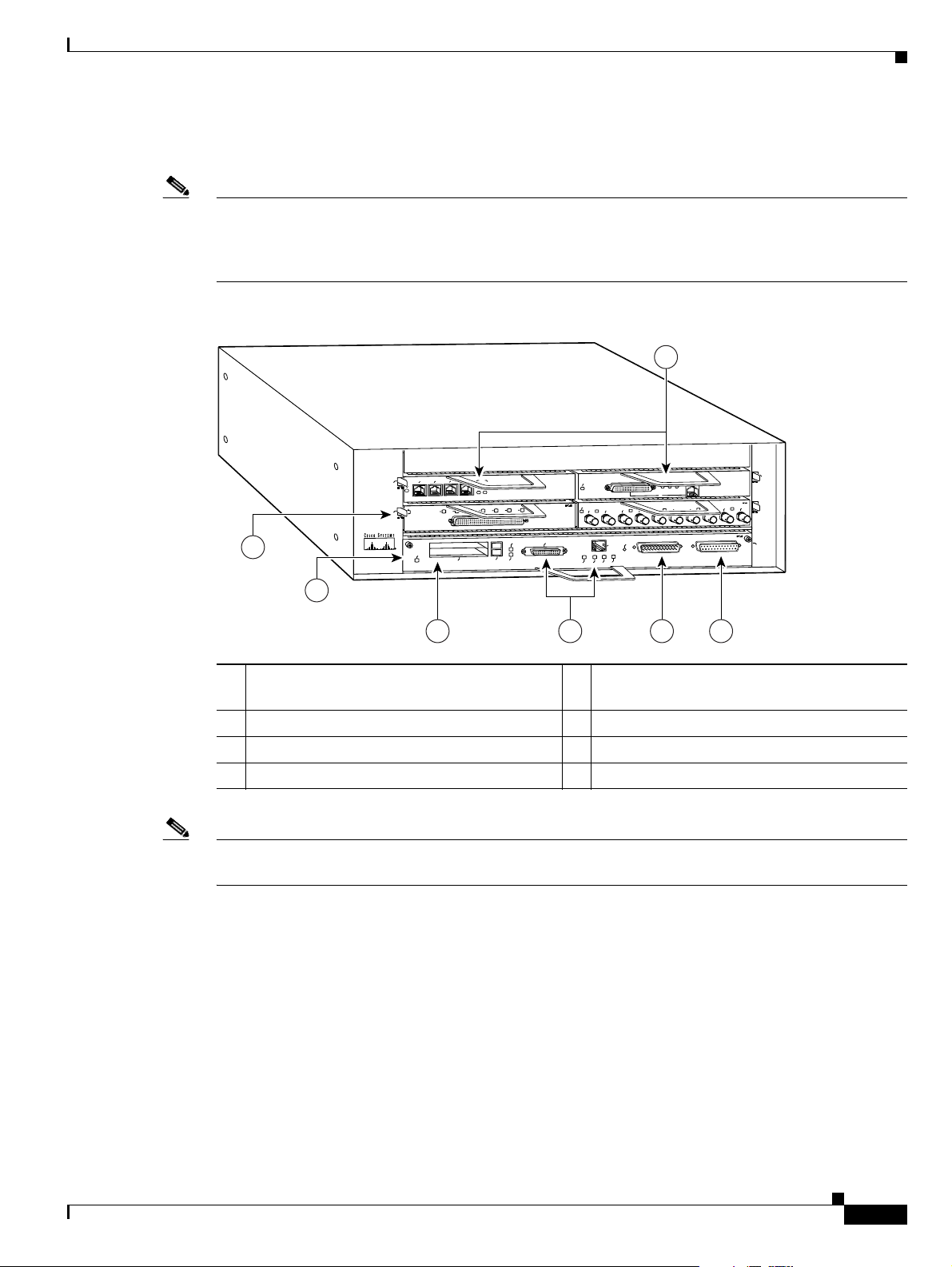
Figure 1-1 Cisco 7204VXR Router—Front View
Cisco 7204VXR Overview
1 Port adapters 5 Optional Fast Ethernet interface (MII port and
RJ-45 port)
2 Port adapter lever 6 Auxiliary port
3 I/O controller 7 Console port
4 PC Card slots
Note In Figure 1-1, a blank port adapter is installed in slot 3. To ensure adequate airflow across the port
adapters, each port adapter slot must be filled with either a port adapter or a blank port adapter.
The rear of the Cisco 7204VXR router provides access to the network processing engine or network
services engine and up to two power supplies. (See
Figure 1-2.)
OL-5013-09
Cisco 7200 VXR Installation and Configuration Guide
1-5
Page 24
Cisco 7204VXR Overview
84396
N
E
T
W
O
R
K
P
R
O
C
E
S
S
IN
G
E
N
G
IN
E
-3
0
0
1
5
2
43
8 976
Chapter 1 Cisco 7200 VXR Product Overview
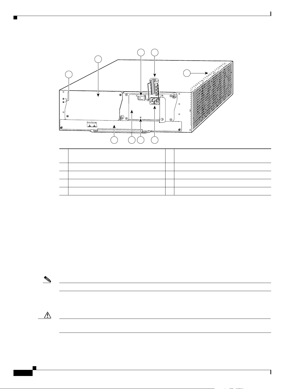
Figure 1-2 Cisco 7204VXR Router—Rear View
1 Chassis grounding receptacles 6 Network processing engine or network
services engine
2 Power supply filler plate 7 AC-input power supply
3 Power switch 8 PWR OK LED
4 AC power cable-retention clip 9 AC power supply receptacle
5 Internal fans
The NPE-G2 and NPE-G1 have external connectors and status LEDs for the three Gigabit Ethernet
interfaces as well as console and auxiliary ports. The network processing engines NPE-100 through
NPE-400 or network services engine (NSE-1) have no external connectors or LEDs. There is a handle
for removing and installing the network processing engine or network services engine and two captive
installation screws for securing it to the chassis.
The Port Adapter Jacket Card is supported in the I/O controller slot.
The Cisco 7204VXR router comes equipped with one 280W AC-input power supply. (A 280W DC-input
power supply option is available.) In
Figure 1-2, a Cisco 7204VXR router is configured with a single
AC-input power supply. (A power supply filler plate is installed over the second power supply bay.) A
fully configured Cisco
7204VXR router operates with only one installed power supply; however, a
second, optional power supply of the same type provides hot-swappable, load-sharing, redundant power.
Note The Cisco 7204VXR does not support a mixture of AC- and DC-input power.
The power supply has the router’s main power switch and either an AC-input power receptacle or a
Caution Do not mix power supplies in the Cisco 7204VXR. In dual power supply router configurations, both
hardwired DC-input power cable (depending on the type of installed power supply).
power supplies must be of the same type (two AC-input power supplies or two DC-input power supplies).
Adjacent to the power supply bays are two chassis grounding receptacles that provide a chassis ground
connection for ESD equipment or a two-hole grounding lug. (See
Figure 1-2.)
1-6
Cisco 7200 VXR Installation and Configuration Guide
OL-5013-09
Page 25

Chapter 1 Cisco 7200 VXR Product Overview
Three internal fans draw cooling air into the chassis and across internal components to maintain an
acceptable operating temperature. (See
inside the chassis.
Caution To ensure the proper flow of cooling air across the internal components, make sure blank port adapters
are installed in unoccupied port adapter slots, and power supply filler plates are installed in unoccupied
power supply bays.
The I/O controller, port adapters, Port Adapter Jacket Card, power supplies, and network processing
engine or network services engine slide into their respective chassis slots and connect directly to the
routers midplane; there are no internal cables to connect. The midplane distributes power from the power
supplies to the I/O controller, port adapters, Port Adapter Jacket Card, fan tray, and network processing
engine or network services engine.
The midplane also senses OIR of the port adapters, bridges the PCI buses from the port adapters to
packet memory on the network processing engine or network services engine, arbitrates traffic across
the PCI buses, and generates the clock signals for the port adapters on each PCI bus.
Cisco 7206VXR Overview
Figure 1-2.) The three fans are enclosed in a tray that is located
Note The Port Adapter Jacket Card does not support OIR. However, the port adapter installed in the Port
Adapter Jacket Card does support OIR.
The Cisco 7204VXR operates as either a tabletop or a rack-mounted unit. A rack-mount kit is standard
equipment included with all Cisco
provides the hardware needed to mount the router in a standard 19-inch equipment rack or a 2-post rack.
Steps for installing the Cisco
VXR routers and are explained in Chapter 3, “
rack-mounting your Cisco 7204VXR, place it on a sturdy tabletop or platform.
A fully configured Cisco 7204VXR, with two installed power supplies and all chassis slots filled, weighs
approximately 50 pounds (22.7 kilograms [kg]). For clearance requirements and rack-mount installation
considerations, see
on page 2-3.
Chapter 2, “Preparing for Installation,” the “Site Requirement Guidelines” section
Cisco 7206VXR Overview
The Cisco 7206VXR supports multiprotocol, multimedia routing and bridging with a wide variety of
protocols and port adapter combinations available for Cisco 7200 series routers. In addition, the
Cisco
7206VXR midplane provides increased support for multiple high-bandwidth port adapters.
Note The Cisco 7206VXR is also available as a router shelf in a Cisco AS5800 Universal Access Server. If
your Cisco
Cisco AS5800 Universal Access Server publications that shipped with the access server.
7206VXR is installed as a router shelf, use this publication in conjunction with the
7200 VXR routers when they are shipped from the factory. The kit
7204VXR router in an equipment rack are the same for all Cisco 7200
Installing a Cisco 7200 VXR Router.” If you are not
OL-5013-09
The Cisco 7206VXR has six slots (slot 1 through slot 6) for port adapters, one slot for an input/output
(I/O) controller, and one slot for a network processing engine or network services engine. You can place
the port adapters in any of the six available slots.
The front of the Cisco 7206VXR provides access to the I/O controller and up to six network interface
port adapters. (See
Figure 1-3.)
Cisco 7200 VXR Installation and Configuration Guide
1-7
Page 26
Cisco 7206VXR Overview
2
E
T
H
E
R
N
E
T
-
1
0
B
F
L
E
N
R
X
0
1
2
3
4
TX
R
X
TX
R
X
TX
R
X
TX
R
X
TX
0
4
1
3
5
6
F
A
S
T
S
E
R
I
A
L
E
N
T
D
T
C
R
D
R
C
L
B
C
D
T
D
T
C
R
D
R
C
L
B
C
D
T
D
T
C
R
D
R
C
L
B
C
D
T
D
T
C
R
D
R
C
L
B
C
D
TOKEN RING
0
1
2
3
Cisco 7200
Series VXR
MII
EN
RJ45
EN
RJ45
LINK
1O PWR
OK
R
J
-
4
5
C
P
U
R
E
S
E
T
FAST ETHERNET INPUT/OUTPUT CONTROLLER
ENABLED
PCMCIA
EJECT
SLOT 0
SLOT 1
FE MII
ETHERNET 10BT
E
N
A
B
L
E
D
0
2
1
3
L
I
N
K
0
1
2
3
E
N
A
B
L
E
D
M
I
I
L
IN
K
R
J
4
5
F
A
S
T
E
T
H
E
R
N
E
T
0
84517
1
5
3
4
6
2
7 8
Note If you have difficulty installing a processing engine or I/O controller in the lowest slot of a
Chapter 1 Cisco 7200 VXR Product Overview
With the NPE-G1 or NPE-G2 installed and the Port Adapter Jacket Card installed in the I/O controller
slot, an additional port adapter slot is available.
Cisco
7200 VXR router that is rack-mounted, remove the port adapters, processing engine and I/O
controller from the chassis and reinstall them. Install the processing engine and I/O controller in the
lowest slots first, then populate the slots above them, in a bottom-to-top order.
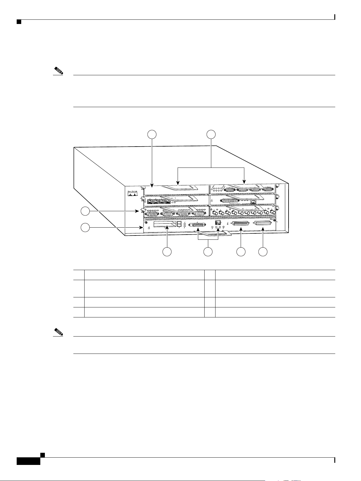
Figure 1-3 Cisco 7206VXR Router—Front View
1 Blank port adapter 5 PC Card slots
2 Port adapters 6 Optional Fast Ethernet interface (MII port and
RJ-45 port)
3 Port adapter lever 7 Auxiliary port
4 I/O controller 8 Console port
Note In Figure 1-3, a blank port adapter is installed in slot 5. To ensure adequate airflow across the port
adapters, each port adapter slot must be filled with either a port adapter or a blank port adapter.
Cisco 7200 VXR Installation and Configuration Guide
1-8
OL-5013-09
Page 27
Chapter 1 Cisco 7200 VXR Product Overview
84396
N
E
T
W
O
R
K
P
R
O
C
E
S
S
IN
G
E
N
G
IN
E
-3
0
0
1
5
2
43
8 976
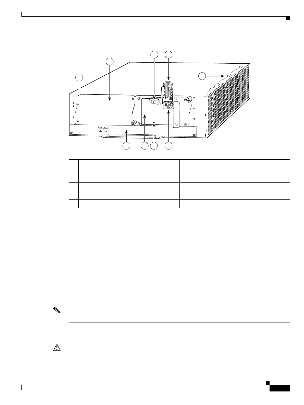
Figure 1-4 Cisco 7206VXR Router—Rear View
Cisco 7206VXR Overview
1 Chassis grounding receptacles 6 Network processing engine or network
services engine
2 Power supply filler plate 7 AC-input power supply
3 Power switch 8 PWR OK LED
4 AC power cable-retention clip 9 AC power supply receptacle
5 Internal fans
The rear of the Cisco 7206VXR router provides access to the network processing engine or network
services engine and up to two power supplies. (See
Figure 1-4.)
The NPE-G2 and NPE-G1 have external connectors and status LEDs for the three Gigabit Ethernet
interfaces as well as console and auxiliary ports. The network processing engines NPE-100 through
NPE-400 or network services engine (NSE-1) have no external connectors or LEDs. There is a handle
for removing and installing the network processing engine or network services engine and two captive
installation screws for securing it to the chassis.
The Port Adapter Jacket Card is supported in the I/O controller slot.
The Cisco 7206VXR router comes equipped with one 280W AC-input power supply. (A 280W DC-input
power supply option is available.) In
Figure 1-4, a Cisco 7206VXR router is configured with a single
AC-input power supply. (A power supply filler plate is installed over the second power supply bay.) A
fully configured Cisco
7206VXR router operates with only one installed power supply; however, a
second, optional power supply of the same type provides hot-swappable, load-sharing, redundant power.
Note The Cisco 7206VXR does not support a mixture of AC- and DC-input power.
The power supply has the router’s main power switch and either an AC-input power receptacle or a
hardwired DC-input power cable (depending on the type of installed power supply).
Caution Do not mix power supplies in the Cisco 7206VXR. In dual power supply router configurations, both
OL-5013-09
power supplies must be of the same type (two AC-input power supplies or two DC-input power supplies).
Cisco 7200 VXR Installation and Configuration Guide
1-9
Page 28

Field-Replaceable Units
Caution To ensure the proper flow of cooling air across the internal components, make sure blank port adapters
Chapter 1 Cisco 7200 VXR Product Overview
Adjacent to the power supply bays are two chassis grounding receptacles that provide a chassis ground
connection for ESD equipment or a two-hole grounding lug. (See
Figure 1-4.)
Three internal fans draw cooling air into the chassis and across the internal components to maintain an
acceptable operating temperature. (See
Figure 1-4.) The three fans are enclosed in a tray that is located
inside the chassis.
are installed in unoccupied port adapter slots, and power supply filler plates are installed in unoccupied
power supply bays.
The I/O controller, port adapters, Port Adapter Jacket Card, power supplies, and network processing
engine or network services engine slide into their respective chassis slots and connect directly to the
router’s midplane; there are no internal cables to connect. The midplane distributes power from the
power supplies to the I/O controller, port adapters, Port Adapter Jacket Card, fan tray, and network
processing engine or network services engine.
The midplane also senses OIR of the port adapters, bridges the PCI buses from the port adapters to
packet memory on the network processing engine or network services engine, arbitrates traffic across
the PCI buses, and generates the clock signals for the port adapters on each PCI bus.
Note The Port Adapter Jacket Card does not support OIR. However, the port adapter installed in the Port
Adapter Jacket Card does support OIR.
The Cisco 7206VXR operates as either a tabletop or a rack-mounted unit. A rack-mount kit is standard
equipment included with all Cisco
provides the hardware needed to mount the router in a standard 19-inch equipment rack or a 2-post rack.
Steps for installing the Cisco
VXR routers and are explained in Chapter 3, “
rack-mounting your Cisco 7206VXR, place it on a sturdy tabletop or platform.
A fully configured Cisco 7206VXR, with two installed power supplies and all chassis slots filled, weighs
approximately 50 pounds (22.7 kilograms [kg]). For clearance requirements and rack-mount installation
considerations, see
Chapter 2, “Preparing for Installation,” the “Site Requirement Guidelines” section
on page 2-3.
Field-Replaceable Units
The Cisco 7200 VXR routers are easy to service; many of their major components are field-replaceable
units (FRUs). The following sections describe Cisco
• Network Processing Engine or Network Services Engine, page 1-11
• Input/Output Controller, page 1-32
• LED Descriptions, page 1-40
7200 VXR routers when they are shipped from the factory. The kit
7206VXR router in an equipment rack are the same for all Cisco 7200
Installing a Cisco 7200 VXR Router.” If you are not
7200 VXR router FRUs:
1-10
• Port Adapters and Service Adapters, page 1-47
• Port Adapter Jacket Card, page 1-48
• Power Supplies, page 1-49
• Chassis, page 1-51
• CompactFlash Disks, Flash Disks, and PC Cards, page 1-52
Cisco 7200 VXR Installation and Configuration Guide
OL-5013-09
Page 29

Chapter 1 Cisco 7200 VXR Product Overview
• Rack-Mount and Cable-Management Kit, page 1-53
Note Replacement instructions for removing and replacing FRUs are contained in separate online documents.
For example, if you need to replace an AC power supply in your Cisco
280-Watt AC-Input Power Supply Replacement Instructions publication. Replacement instructions are
available on the Documentation DVD and on Cisco.com.
Network Processing Engine or Network Services Engine
The network processing engine or network services engine maintains and executes the system
management functions for Cisco
services engine shares the system memory and environmental monitoring functions with the I/O
controller.
Because the NPE-G1 and NPE-G2 contain I/O functionality, the Cisco 7200 VXR routers can operate
with no I/O controller with an NPE-G1 or NPE-G2 installed. With both an I/O controller and the NPE-G1
or NPE-G2 installed, the NPE-G1 or NPE-G2 enhances the I/O controller functionality.
Cisco 7200 VXR routers support nine versions of the network processing engine: NPE-G2, NPE-G1,
NPE-400, NPE-300, NPE-225, NPE-200, NPE-175, NPE-150, and NPE-100. These network processing
engines have the same functionality; however, their performance differs because of the microprocessor
type and the type of memory for packet data (SRAM and DRAM, or SDRAM) that each network
processing engine provides.
7200 VXR routers. Also, the network processing engine or network
Field-Replaceable Units
7200 VXR router, refer to the
Cisco 7200 VXR routers also support the NSE-1, which consists of two modular boards: the processor
engine board and the network controller board. The NSE-1 Parallel eXpress Forwarding (PXF) processor
works with the Route Processor to provide accelerated packet switching, as well as accelerated IP
Layer
3 feature processing.
Note Detailed instructions for removing and replacing the network processing engines or network services
engine are contained in the online Network Processing Engine and Network Services Engine Installation
and Configuration publication. It is available on the Documentation DVD and on Cisco.com.
The network processing engines and network services engine consist of the following components:
• Reduced instruction set computing (RISC) microprocessor
–
The NPE-G2 uses a Motorola Freescale 7448 microprocessor that operates at an internal clock
speed of 1.67 GHz.
–
The NPE-G1 uses a BCM 1250 microprocessor that operates at an internal clock speed of 700 MHz.
–
The NSE-1 uses an RM7000 microprocessor that operates at an internal clock speed of
262
MHz.
–
The NPE-400 uses an RM7000 microprocessor that operates at an internal clock speed of
350
MHz.
–
The NPE-300 uses an RM7000 microprocessor that operates at an internal clock speed of
262
MHz.
–
The NPE-225 has an RM5271 microprocessor that operates at an internal clock speed of
262
MHz.
OL-5013-09
–
The NPE-200 has an R5000 microprocessor that operates at an internal clock speed of
200
MHz.
Cisco 7200 VXR Installation and Configuration Guide
1-11
Page 30

Field-Replaceable Units
–
The NPE-175 has an RM5270 microprocessor that operates at an internal clock speed of
200
MHz.
–
The NPE-100 and NPE-150 have an R4700 microprocessor that operates at an internal clock
speed of 150 MHz.
• System controller
–
The NPE-G2 has one system controller that provides processor access to the three midplane PCI
buses, and also holds the system memory and environmental monitoring functions.
–
The NPE-G1 BCM 1250 maintains and executes the system management functions for the
Cisco
7200 VXR routers and also holds the system memory and environmental monitoring
functions.
–
The NSE-1 has one system controller that provides processor access to the midplane and single
I/O controller PCI buses. The system controller also allows port adapters on either of the two
midplane PCI buses to access SDRAM.
–
The NPE-400 has one system controller that provides system access.
–
The NPE-300 has two system controllers that provide processor access to the two midplane and
single I/O controller PCI buses. The system controller also allows port
two midplane PCI buses to access SDRAM.
–
The NPE-175 and NPE-225 have one system controller that provides processor access to the two
midplane and single I/O controller PCI buses. The system
port
adapters on either of the two midplane PCI buses to access SDRAM.
Chapter 1 Cisco 7200 VXR Product Overview
adapters on either of the
controller also allows the
–
The NPE-100, NPE-150, and NPE-200 have a system controller that uses direct memory access
(DMA) to transfer data between DRAM and packet SRAM on the network processing engine.
• Upgradable memory modules
–
The NPE-G2 uses SDRAM for storing all packets received or sent from network interfaces, The
SDRAM also stores routing tables and network accounting applications. A single SDRAM
memory array in the system allows concurrent access by port adapters and the processor.
–
The NPE-G1 uses SDRAM for storing all packets received or sent from network interfaces. The
SDRAM also stores routing tables and network accounting applications. Two independent
SDRAM memory arrays in the system allow concurrent access by port
processor.
–
The NSE-1 uses SDRAM for providing code, data, and packet storage.
–
The NPE-400 uses SDRAM for storing all packets received or sent from network interfaces. The
SDRAM memory array in the system allows concurrent access by port
processor.
–
The NPE-300 uses SDRAM for storing all packets received or sent from network interfaces. The
SDRAM also stores routing tables and network accounting applications. Two independent
SDRAM memory arrays in the system allow concurrent access by port
processor.
–
The NPE-175 and NPE-225 use SDRAM for providing code, data, and packet storage.
–
The NPE-100, NPE-150, and NPE-200 use DRAM for storing routing tables, network
accounting applications, packets of information in preparation for process switching, and
packet buffering for SRAM overflow (except in the NPE-100, which contains no packet
SRAM). The standard configuration is 32 MB, with up to 128 MB available through single
in-line memory module (SIMM) upgrades.
adapters and the
adapters and the
adapters and the
1-12
• Packet SRAM for storing packets of information in preparation for fast switching
Cisco 7200 VXR Installation and Configuration Guide
OL-5013-09
Page 31

Chapter 1 Cisco 7200 VXR Product Overview
The NPE-150 has 1 MB of SRAM and the NPE-200 has 4 MB of SRAM. No other network
processing engine or network services engine has SRAM.
• Cache memory
–
The NPE-G2 has two levels of cache: a primary and a secondary cache that are internal to the
microprocessor, with the secondary unified cache for data and instruction.
–
The NPE-G1 has two levels of cache: a primary and a secondary cache that are internal to the
microprocessor, with the secondary unified cache for data and instruction.
–
The NSE-1 has three levels of cache: a primary and a secondary unified cache that are internal
to the microprocessor, and a tertiary 2-MB external cache.
–
The NPE-400 has three levels of cache: a primary and a secondary cache that are internal to the
microprocessor, and a tertiary 4-MB external cache that provides additional high-speed storage
for data and instructions.
–
The NPE-300 has three levels of cache: a primary and a secondary cache that are internal to the
microprocessor, and a tertiary 2-MB external cache that provides additional high-speed storage
for data and instructions.
–
The NPE-225 has two levels of cache: a primary cache that is internal to the processor and a
secondary 2-MB external cache that provides additional high-speed storage for data and
instructions.
–
The NPE-200 has unified cache SRAM that functions as the secondary cache for the
microprocessor. (The primary cache is within the microprocessor.)
Field-Replaceable Units
–
The NPE-175 has two levels of cache: a primary cache that is internal to the processor and a
secondary 2-MB external cache that provides additional high-speed storage for data and
instructions.
–
The NPE-150 has unified cache SRAM that functions as the secondary cache for the
microprocessor. (The primary cache is within the microprocessor.)
–
The NPE-100 has unified cache SRAM that functions as the secondary cache for the
microprocessor. (The primary cache is within the microprocessor.)
• Two environmental sensors for monitoring the cooling air as it leaves the chassis
• Boot ROM for storing sufficient code for booting the Cisco IOS software; the NPE-G2, NPE-G1,
NSE-1, NPE-400, NPE-300, NPE-225, NPE-200, and NPE-175 have boot ROM.
The network processing engines and network services engine perform the following system management
functions:
• Sending and receiving routing protocol updates
• Managing tables, caches, and buffers
• Monitoring interface and environmental status
• Providing Simple Network Management Protocol (SNMP) management through the console and
Telnet interface
• Accounting for and switching of data traffic
• Booting and reloading images
• Managing port adapters (recognition and initialization during online insertion and removal)
OL-5013-09
The following figures and memory tables provide information about your NPE or NSE:
• NPE-G2 is represented by Figure 1-5. Table 1-2 lists NPE-G2 memory specifications, and Table 1-3
lists memory configurations.
Cisco 7200 VXR Installation and Configuration Guide
1-13
Page 32

Field-Replaceable Units
Chapter 1 Cisco 7200 VXR Product Overview
• NPE-G1 is represented by Figure 1-6. Table 1-4 lists NPE-G1 memory specifications, and Table 1-5
lists memory configurations.
• NSE-1 is represented by Figure 1-7. Table 1-6 lists NSE-1 memory specifications, and Ta b l e 1-7
lists memory configurations.
• The NPE-400 is represented by Figure 1-8. Table 1-8 lists NPE-400 memory specifications, and
Table 1-9 lists memory configurations.
• NPE-300 is represented by Figure 1-9. Tab l e 1-10 lists NPE-300 memory specifications, and
Table 1-11 lists memory configurations.
• NPE-225 is represented by Figure 1-10. Table 1-12 lists NPE-225 memory specifications, and
Table 1-13 lists memory configurations.
• NPE-200 is represented by Figure 1-11. Table 1-14 lists NPE-200 memory specifications, and
Table 1-15 lists memory configurations.
• NPE-175 is represented by Figure 1-12. Table 1-16 lists NPE-175 memory specifications, and
Table 1-17 lists memory configurations.
• NPE-150 is represented by Figure 1-13. Table 1-18 lists NPE-150 memory specifications, and
Table 1-19 lists memory configurations.
• NPE-100 is represented by Figure 1-14. Table 1-20 lists NPE-100 memory specifications, and
Table 1-21 lists memory configurations.
1-14
Cisco 7200 VXR Installation and Configuration Guide
OL-5013-09
Page 33

Chapter 1 Cisco 7200 VXR Product Overview
3
1
9
7
8
10
2
5
6
4
Figure 1-5 NPE-G2
Field-Replaceable Units
1 Midplane connectors 6 Flash memory (U13)
2 Boot ROM (U24) 7 DIMM (socket—S1)
3 NVRAM (on bottom of board—U17) 8 Temperature sensor (inlet—U23)
4 Temperature sensor (outlet—U20) 9 Processor (U30)
5 Flash memory (U19) 10 Keying post
Table 1-2 lists the NPE-G2 memory specification, and Tab l e 1-3 lists the factory-installed SDRAM
configurations and their product numbers.
Ta b l e 1-2 NPE-G2 Memory Specifications
Component Location
Memory Type Size Quantity Description
on the NPE-G2 Board
SDRAM 1 GB 1 1-GB DDR SDRAM S1
Boot ROM 512 KB 1 Reprogrammable Boot ROM
U24
for the ROM monitor program
Flash memory
(also known
64 MB 1 Contains the default boot
helper (boot loader) image
U19 and U13
as bootflash)
NVRAM 2 MB 1 Nonvolatile EPROM for the
U17
system configuration file
OL-5013-09
Cisco 7200 VXR Installation and Configuration Guide
1-15
Page 34

Field-Replaceable Units
66435
GIGABIT ETHERNET 0/1
RJ45 GBIC
EN
RX TX
LINK
CONSOLE AUX
GIGABIT ETHERNET 0/1
RJ45 GBIC
EN
RX TX
LINK
GIGABIT ETHERNET 0/1
RJ45 GBIC
EN
RX TX
LINK
CPU
RESET
COMPACT FLASH
POWER
ON
SLOT
ACTIVE
NETWORK PROCESSING ENGINE - G1
5
4
3
6
8
7
9
10
1
2
Chapter 1 Cisco 7200 VXR Product Overview
Table 1-2 NPE-G2 Memory Specifications (continued)
Memory Type Size Quantity Description
Primary cache 32 KB (16 KB
instruction,
16
KB data)
Secondary
1 MB — Motorola Freescale 7448
cache
Ta b l e 1-3 NPE-G2 SDRAM Configuration—Configurable Memory Only
— Motorola Freescale 7448
processor, internal cache
secondary cache
Total SDRAM SDRAM Bank Quantity
1 GB S1 1-GB DIMM
Figure 1-6 NPE-G1
Component Location
on the NPE-G2 Board
U30
U30
1 Midplane connectors 6 Boot ROM
2 Flash memory 7 NVRAM
3 Temperature sensor 8 DIMM 2
4 Processor 9 Temperature sensor
5 Keying post 10 DIMM 1
Table 1-4 lists the NPE-G1 memory specification, and Tab l e 1-5 lists the factory-installed SDRAM
configurations and their product numbers.
1-16
Cisco 7200 VXR Installation and Configuration Guide
OL-5013-09
Page 35

Chapter 1 Cisco 7200 VXR Product Overview
Ta b l e 1-4 NPE-G1 Memory Specifications
Memory Type Size Quantity Description
SDRAM 128 MB,
Boot ROM 512 KB 1 Reprogrammable
Flash Memory 16 MB 1 Contains the default
NVRAM 512 KB 1 Nonvolatile
Primary cache 32 KB
Secondary cache 512 KB — BCM 1250 system,
256 MB,
512 MB
(16 KB
instruction,
16 KB data)
Field-Replaceable Units
Component Locat ion
on the NPE-G1
Board
2 128-MB, 256-MB,
J3, J4
or 512-MB
SODIMMs
U1
Boot ROM for the
ROM monitor
program
U25 and U26
boot helper (boot
loader) image
U7
EPROM for the
system
configuration file
— BCM 1250 system,
U22
internal cache
U22
internal, unified
cache
Ta b l e 1-5 NPE-G1 SDRAM SODIMM Memory Configurations—Configurable Memory Only
Total SDRAM SDRAM Bank Quantity Product Number
256 MB J3 and J4 2 128-MB SODIMMs MEM-NPE-G1-256MB=
512 MB J3 and J4 2 256-MB SODIMMs MEM-NPE-G1-512MB=
1 GB J3 and J4 2 512-MB SODIMMs MEM-NPE-G1-1GB=
OL-5013-09
Cisco 7200 VXR Installation and Configuration Guide
1-17
Page 36

Field-Replaceable Units
66418
N
ETW
OR
K
P
R
O
C
ESS
IN
G
E
NG
IN
E-200
1
8
5
7
6
3
2
4
9
10
11
12
13
Chapter 1 Cisco 7200 VXR Product Overview
Figure 1-7 NSE-1
1 Network controller board 8 Midplane connectors
2 Keying post 9 Boot ROM (U1)
3 System controller 10 Temperature sensor
4 Processor engine board 11 SDRAM
5 Captive installation screw 12 Parallel eXpress Forwarding engine (PXF
processor)
6 RM7000 microprocessor 13 Temperature sensor
7 Handle
Table 1-6 lists the NSE-1 memory specifications, and Table 1-7 lists the NSE-1 factory-installed
SDRAM configurations and their product numbers.
Ta b l e 1-6 NSE-1 Memory Specifications
Memory Type Size Quantity Description Location
SDRAM 128 or 256 MB 1 SDRAM slot 128- or 256-MB DIMM U15
Boot ROM 512 KB 1 OTP ROM for the ROM
Primary cache 16 KB
(instruction),
16 KB (data)
— RM7000 processor,
monitor program
primary internal cache
U1
U22
1
1-18
Cisco 7200 VXR Installation and Configuration Guide
OL-5013-09
Page 37

Chapter 1 Cisco 7200 VXR Product Overview
N
ETW
O
R
K
P
R
O
CE
S
SIN
G
EN
G
IN
E-4
00
N
ETW
O
R
K
P
R
O
CE
S
SIN
G
EN
G
IN
E-4
00
66411
9
10
11
1
7
8
65
2
3
4
Table 1-6 NSE-1 Memory Specifications (continued)
Field-Replaceable Units
Memory Type Size Quantity Description Location
Secondary
cache
256 KB — RM7000 processor,
internal, unified
U22
instruction and data cache
Tertiary cache 2 MB (fixed) — RM7000 processor,
external cache
U7, U9,
U12, U14,
U17
1. Location on processing engine board. See Figure 1-7.
Ta b l e 1-7 NSE-1 SDRAM DIMM Memory Configurations
Total SDRAM SDRAM Bank Quantity Product Number
128 MB U15 1 128-MB DIMM MEM-SD-NPE-128MB=
256 MB U15 1 256-MB DIMM MEM-SD-NSE-256MB=
Figure 1-8 NPE-400
1
1 Temperature sensor (U31) 7 Midplane connector
2 Keying post 8 Boot ROM (U7)
3 RM7000 microprocessor 9 Temperature sensor
4 System controller 10 SODIMM (J1)
5 Captive installation screw 11 Standoff and screw
6 Handle
Cisco 7200 VXR Installation and Configuration Guide
OL-5013-09
1-19
Page 38

Field-Replaceable Units
Chapter 1 Cisco 7200 VXR Product Overview
Table 1-8 lists the NPE-400 memory specifications, and Tab l e 1-9 lists factory-installed SDRAM
configurations and their product numbers.
Ta b l e 1-8 NPE-400 Memory Specifications
Memory Type Size Quantity Description Location
SDRAM-configurable 128, 256, or
512 MB
Boot ROM 512 KB 1 OTP1 ROM for the ROM
1 128-, 256-, or 512-MB
SODIMM
J1
U7
monitor program
Primary cache 16 KB
(instruction),
16
KB (data)
Secondary cache 256 KB (fixed) — RM7000 processor, unified,
— RM7000 processor,
integrated cache
U38
U38
internal cache
Tertiary cache 4 MB (fixed) — RM7000 processor, external
cache
U2, U26,
U27, U28,
U37
1. OTP = one-time programmable
Ta b l e 1-9 NPE-400 SDRAM SODIMM Memory Configurations
Total SDRAM Bank 1 Quantity Product Number
128 MB J1 1 128-MB SODIMM MEM-NPE-400-128MB=
256 MB J1 1 256-MB SODIMM MEM-NPE-400-256MB=
512 MB J1 1 512 MB SODIMM MEM-NPE-400-512MB=
1-20
Cisco 7200 VXR Installation and Configuration Guide
OL-5013-09
Page 39

Chapter 1 Cisco 7200 VXR Product Overview
66410
NE
T
W
O
R
K
P
R
O
C
ES
S
IN
G
E
N
G
IN
E
-30
0
11
2
1
12
13
3
4
5
14
15
16
109876
Figure 1-9 NPE-300
Field-Replaceable Units
1 Midplane connectors 9 RM7000 microprocessor
2 Keying post 10 Temperature sensor (U42)
3 DIMM 3 (U44) 11 Keying post
4 Bank 1 (user configurable) 12 Temperature sensor
5 DIMM 2 (U45) 13 Boot ROM (U1)
6 Captive installation screw 14 DIMM 0 (U16)
7 Handle 15 Bank 0 (fixed size)
8 System controllers 16 U15 never populated
Table 1-10 lists the NPE-300 memory specifications, and Ta ble 1-11 lists factory-installed SDRAM
configurations and their product numbers.
Ta b l e 1-10 NPE-300 Memory Specifications
Memory Type Size Quantity Description Location
SDRAM 32 to 256 MB 1 configurable2
Boot ROM 512 KB 1 OTP4 ROM for the ROM monitor
Primary cache 16 KB
1
bank with 2
SDRAM slots
32-, 64-, or 128-MB DIMMs
(based on maximum SDRAM
required)
Bank 1:
U45 and
3
U44
Socket
U1
(instruction),
16
KB (data)
— RM7000 processor, internal cache U49
program
OL-5013-09
Cisco 7200 VXR Installation and Configuration Guide
1-21
Page 40

Field-Replaceable Units
Chapter 1 Cisco 7200 VXR Product Overview
Table 1-10 NPE-300 Memory Specifications (continued)
Memory Type Size Quantity Description Location
Secondary
cache
256 KB — RM7000 processor, internal,
unified instruction and data cache
U49
Tertiary cache 2 MB (fixed) — RM7000 processor, external cache U7, U8,
U9, U10,
U17
1. Location on processing engine board. See Figure 1-9.
2. Bank 0 is used exclusively for packet memory and is not user configurable.
3. Bank 1 contains the Cisco IOS software, processor memory, and packet memory.
4. OTP = one-time programmable
Note The NPE-300 contains two banks of SDRAM. Both SDRAM banks are used for all packet memory
requirements; however, bank 0 is used exclusively for packet memory and is set at a fixed configuration
in the factory.
Bank 1 contains two user-configurable SDRAM slots, DIMM slot 2 and DIMM slot 3 (see Figure 1-9).
Both slots in bank 1 can be populated by DIMMs of different sizes; however, the size of the DIMM in
slot
2 must be greater than or equal to the size of the DIMM in slot 3, and the size of the DIMM in slot 3
can be zero.
1
Ta b l e 1-11 NPE-300 SDRAM DIMM Memory Configurations
Total SDRAM SDRAM Bank 1
323 MB + 32 MB
U45 (DIMM slot 2
1
Quantity Product Number
1 32-MB DIMM MEM-SD-NPE-32MB=
2
only)
323 MB + 64 MB U45 and U44
or
2 32-MB DIMMs
or
MEM-SD-NPE-32MB=
U45 1 64-MB DIMM MEM-SD-NPE-64MB=
323 MB + 128 MB U45 and U44
or
2 64-MB DIMMs
or
MEM-SD-NPE-64MB=
U45 1 128-MB DIMM MEM-SD-NPE-128MB=
323 MB + 256 MB U45 and U44 2 128-MB DIMMs MEM-SD-NPE-128MB=
1. There are two user-upgradable SDRAM slots in bank 1. (Bank 0 is used exclusively for packet memory and is set at a fixed
configuration in the factory.)
2. These products are also available as SDRAM upgrades. To order an upgrade, add an equal sign (=) after the product number,
for example, MEM-SD-NPE-128MB=.
3. This 32 MB is fixed memory in SDRAM bank 0, socket U16. Socket U15 is never populated.
1-22
Cisco 7200 VXR Installation and Configuration Guide
OL-5013-09
Page 41

Chapter 1 Cisco 7200 VXR Product Overview
66417
N
ET
W
O
R
K PR
OC
E
SS
IN
G EN
GIN
E-2
00
1
7
4
65
2
3
8
9
10
Figure 1-10 NPE-225
Field-Replaceable Units
1 Network controller board 6 Handle
2 System controller 7 Midplane connectors
3 Processor engine board 8 Boot ROM (U1)
4 Captive installation screw 9 Temperature sensor
5 RM5271 microprocessor 10 SDRAM DIMM (U15)
Table 1-12 lists the NPE-225 memory specifications, and Ta ble 1-13 lists factory-installed SDRAM
configurations and their product numbers.
Cisco 7200 VXR Installation and Configuration Guide
OL-5013-09
1-23
Page 42

Field-Replaceable Units
Chapter 1 Cisco 7200 VXR Product Overview
Ta b l e 1-12 NPE-225 Memory Specifications
Memory Type Size Quantity Description Location
SDRAM 64, 128, 256 MB 1 SDRAM slot 64-MB, 128- MB,
U15
or 256-MB
SDRAM DIMM
Boot ROM 512 KB — One-time
U1
programmable
ROM
Primary cache 16 KB (instruction),
16
KB (data)
— RM527x
processor, internal
U4
cache
32 KB (instruction),
32
KB (data)
— RM527x
processor, internal
U4
cache
Secondary cache 2 MB 4 chips, each 512K
by 8 bits wide
RM527x
processor, unified
U5, U6, U7, U8
external cache
1. Location on processing engine board. See Figure 1-10.
Ta b l e 1-13 NPE-225 SDRAM DIMM Memory Configurations
Total SDRAM Bank Quantity Product Number
64 MB U15 1 64-MB DIMM MEM-SD-NPE-64MB=
128 MB U15 1 128-MB DIMM MEM-SD-NPE-128MB=
256 MB U15 1 256-MB DIMM MEM-SD-NSE-256MB=
1
1-24
Cisco 7200 VXR Installation and Configuration Guide
OL-5013-09
Page 43

Chapter 1 Cisco 7200 VXR Product Overview
66420
U52
U42
U25
U11
N
ETW
OR
K
PR
OC
ES
SIN
G
E
NG
IN
E
-200
7
11
10
8
12
4 6
5
3
2
1
9
Figure 1-11 NPE-200
Field-Replaceable Units
1 System controller 7 Midplane connectors
2 R5000 microprocessor 8 Temperature sensor
3 4-MB SRAM (U6, U10, U13, U14, U28, U29,
9 Boot ROM (U92)
U38, and U39)
4 Captive installation screw 10 DRAM SIMMs
5 Handle 11 Bank 1
6 Temperature sensor 12 Bank 2
Table 1-14 lists the NPE-200 memory specifications, and Ta ble 1-15 lists factory-installed DRAM
configurations and their product numbers.
Ta b l e 1-14 NPE-200 Memory Specifications
Memory Type Size Quantity Description Location
DRAM 32 to 128 MB 2 to 4 16- or 32-MB
SIMMs (based
on maximum
SRAM 4 MB 8 8 chips, each
Boot ROM2 256 KB 1 EPROM for the
DRAM required)
being 512K
words x 8 bits
wide
ROM monitor
program
Bank 0: U11 and
U25
Bank 1: U42 and
U52
U6, U10, U13,
U14, U28, U29,
U38, and U39
U92
1
OL-5013-09
Cisco 7200 VXR Installation and Configuration Guide
1-25
Page 44

Field-Replaceable Units
Chapter 1 Cisco 7200 VXR Product Overview
Table 1-14 NPE-200 Memory Specifications (continued)
Memory Type Size Quantity Description Location
Primary cache — — R5000 processor,
U44
1
internal cache
Secondary cache 512 KB 4 R5000 processor,
unified external
U16, U9, U109,
and U107
cache
1. Location on processing engine board. See Figure 1-11.
2. ROM = read-only memory
Note To prevent DRAM errors in the NPE-100, NPE-150, or NPE-200, and to ensure that your system
initializes correctly at startup, DRAM bank
0 (socket U18 and U25, or U11 and U25) must contain no
fewer than two SIMMs of the same type. You may also install two SIMMs of the same type in bank
(socket U4 and U12, or U42 and U52); however, bank 0 must always contain the two largest size SIMMs.
Ta b l e 1-15 NPE-200 DRAM SIMM Memory Configurations
Total
DRAM DRAM Bank 0 Quantity DRAM Bank 1 Quantity Product Number
1
32 MB U11 and U25 2 16-MB SIMMs U42 and U52 — MEM-NPE-32MB=
64 MB U11 and U25 2 32-MB SIMMs U42 and U52 — MEM-NPE-64MB=
128 MB U11 and U25 2 32-MB SIMMs U42 and U52 2 32-MB
MEM-NPE-128MB=
SIMMs
1. These products are also available as DRAM upgrades. For example to upgrade a network processing engine from 32 MB to
64 MB of DRAM, order product number MEM-NPE-64MB=.
1
1-26
Cisco 7200 VXR Installation and Configuration Guide
OL-5013-09
Page 45

Chapter 1 Cisco 7200 VXR Product Overview
66416
N
ET
W
O
R
K PR
OC
E
SS
IN
G EN
GIN
E-1
50
1
7
4
65
2
3
8
9
10
Figure 1-12 NPE-175
Field-Replaceable Units
1 Network controller board 6 Handle
2 System controller 7 Midplane connectors
3 Processor engine board 8 Boot ROM (U1)
4 Captive installation screw 9 Temperature sensor
5 RM5270 microprocessor 10 SDRAM DIMM (U15)
Table 1-16 lists the NPE-175 memory specifications, and Ta ble 1-17 lists memory configurations.
Cisco 7200 VXR Installation and Configuration Guide
OL-5013-09
1-27
Page 46

Field-Replaceable Units
Chapter 1 Cisco 7200 VXR Product Overview
Ta b l e 1-16 NPE-175 Memory Specifications
Memory Type Size Quantity Description Location
SDRAM 64 or 128 MB 1 SDRAM slot DIMM U15
Boot ROM 512 KB — One-time
U1
programmable
ROM
Primary cache 16 KB (instruction),
16
KB (data)
32 KB (instruction),
32
KB (data)
Secondary cache 2 MB 4 chips, each 512K
— RM527x processor,
internal cache
— RM527x processor,
internal cache
RM527x processor,
by 8 bits wide
unified external
U4
U4
U5, U6, U7, U8
cache
1. Location on processing engine board. See Figure 1-12.
Ta b l e 1-17 NPE-175 SDRAM DIMM Memory Configurations
Total SDRAM SDRAM Bank Quantity Product Number
64 MB U15 1 64-MB
MEM-SD-NPE-64MB=
DIMM
128 MB U15 1 128-MB
MEM-SD-NPE-128MB=
DIMM
1
1-28
Cisco 7200 VXR Installation and Configuration Guide
OL-5013-09
Page 47

Chapter 1 Cisco 7200 VXR Product Overview
66424
U12
U4
U25
U18
N
ETW
OR
K
PR
O
C
ES
SING
EN
G
IN
E-150
7
10
9
11
4 6
5
3
2
1
8
Figure 1-13 NPE-150
Field-Replaceable Units
1 System controller 7 Midplane connectors
2 R4700 microprocessor 8 Temperature sensor
3 1-MB SRAM (U700 through U703, U800
9 DRAM SIMMs
through U803)
4 Captive installation screw 10 Bank 1
5 Handle 11 Bank 0
6 Temperature sensor
Table 1-18 lists the NPE-150 memory specifications, and Ta ble 1-19 lists memory configurations.
Ta b l e 1-18 NPE-150 Memory Specifications
Memory Type Size Quantity Description Location
DRAM 32 to 128 MB 2 to 4 16- or 32-MB SIMMs (based
on maximum DRAM
required)
Bank 0: U18 and
U25
Bank 1: U4 and
1
U12
SRAM 1 MB 8 8 chips, each being 128K
words x 9 bits wide
U700 through
U703
U800 through
U803
Boot ROM The NPE-150 uses the boot ROM present on the I/O controller.
Primary cache — — R4700 processor, internal
Secondary cache 512 KB 4 R4700 processor, unified
1. Location on processing engine board. See Figure 1-13.
cache
external cache
U201
U2, U10, U14,
and U26
OL-5013-09
Cisco 7200 VXR Installation and Configuration Guide
1-29
Page 48

Field-Replaceable Units
66433
U12
U4
U25
U18
N
ET
W
O
R
K
PR
O
C
E
SS
IN
G
E
N
G
IN
E-100
6
9
8
10
3 5
4
2
1
7
Note To prevent DRAM errors in the NPE-100, NPE-150, or NPE-200, and to ensure that your system
Chapter 1 Cisco 7200 VXR Product Overview
initializes correctly at startup, DRAM bank
fewer than two SIMMs of the same type. You may also install two SIMMs of the same type in bank
0 (socket U18 and U25, or U11 and U25) must contain no
1
(socket U4 and U12, or U42 and U52); however, bank 0 must always contain the two largest size SIMMs.
Ta b l e 1-19 NPE-150 DRAM SIMM Memory Configurations
Total DRAM DRAM Bank 0 Quantity DRAM Bank 1 Quantity Product Number
1
32 MB U18 and U25 2 16-MB SIMMs U4 and U12 — MEM-NPE-32MB=
64 MB U18 and U25 2 32-MB SIMMs U4 and U12 — MEM-NPE-64MB=
128 MB U18 and U25 2 32-MB SIMMs U4 and U12 2 32-MB
MEM-NPE-128MB=
SIMMs
1. These products are also available as DRAM upgrades. For example, to upgrade a network processing engine from 32 MB to
64 MB of DRAM, order product number MEM-NPE-64MB=.
Figure 1-14 NPE-100
1 System controller 6 Midplane connectors
2 R4700 microprocessor 7 Temperature sensor
3 Captive installation screw 8 DRAM SIMMs
4 Handle 9 Bank 1
5 Temperature sensor 10 Bank 0
Table 1-20 lists the NPE-100 network processing engine memory specifications, and Table 1-21 lists
memory configurations.
Cisco 7200 VXR Installation and Configuration Guide
1-30
OL-5013-09
Page 49

Chapter 1 Cisco 7200 VXR Product Overview
Field-Replaceable Units
Ta b l e 1-20 NPE-100 Memory Specifications
Memory Type Size Quantity Description Location
DRAM 32 to
128
MB
2 to 4 16- or 32-MB SIMMs (based
on maximum DRAM
required)
Bank 0: U18 and U25
Bank 1: U4 and U12
1
Boot ROM The NPE-100 uses boot ROM present on the I/O controller.
Primary cache — — R4700 processor, internal
U201
cache
Secondary
cache
1. Location on processing engine board. See Figure 1-14.
Note To prevent DRAM errors in the NPE-100, NPE-150, or NPE-200, and to ensure that your system
initializes correctly at startup, DRAM bank
fewer than two SIMMs of the same type. You may also install two SIMMs of the same type in bank
512 KB 4 R4700 processor, unified,
external cache
0 (socket U18 and U25, or U11 and U25) must contain no
U2, U10, U14, and U26
1
(socket U4 and U12, or U42 and U52); however, bank 0 must always contain the two largest size SIMMs.
Ta b l e 1-21 NPE-100 DRAM SIMM Memory Configurations
Total DRAM DRAM Bank 0 Quantity DRAM Bank 1 Quantity Product Number
32 MB U18 and U25 2 16-MB
64 MB U18 and U25 2 32-MB
128 MB U18 and U25 2 32-MB
1. These products are also available as DRAM upgrades. For example, to upgrade a network processing engine from 32 MB to
MB of DRAM, order product number MEM-NPE-64MB=.
64
Determining Memory Configuration
To determine the memory configuration of your Cisco 7200 VXR router, use the show version
command. The following example shows an NPE-G1 installed in a Cisco7206VXR router:
Router# show version
Cisco Internetwork Operating System Software
IOS (tm) 7200 Software (C7200-JS-M),
Released Version 12.2(20011220:181136) [biff]
Copyright (c) 1986-2001 by cisco Systems, Inc.
Compiled Fri 21-Dec-01 05:58 by
Image text-base:0x600089B8, data-base:0x6196E000
ROM:System Bootstrap, Version 12.2(20011219:132854)
SIMMs
SIMMs
SIMMs
1
U4 and U12 — MEM-NPE-32MB
U4 and U12 — MEM-NPE-64MB
U4 and U12 2 32-MB
MEM-NPE-128MB
SIMMs
OL-5013-09
(display text omitted)
cisco 7206VXR (NPE-G1) processor (revision 0x00) with 245760K/16384K bytes of memory.
Processor board ID 13250983
Cisco 7200 VXR Installation and Configuration Guide
1-31
Page 50

Field-Replaceable Units
BCM12500 CPU at 500Mhz, Implementation 1, Rev 0.1, 512KB L2 Cache
6 slot VXR midplane, Version 2.0
Input/Output Controller
This section describes five different models of I/O controllers. These models are distinguished from one
another by their Ethernet interface options.
describes their differences.
Note For a description of the configuration commands you need to configure the different interfaces on your
I/O controller, refer to the Input/Output Controller Replacement Instructions document.
Ta b l e 1-22 I/O Controller Descriptions
Product Number Description
C7200-I/O-GE+E 1 Gigabit Ethernet and 1 Ethernet port; equipped with a GBIC receptacle for
C7200-I/O-2FE/E 2 autosensing Ethernet/Fast Ethernet ports; equipped with 2 RJ-45 receptacles
C7200-I/O-FE
C7200-I/O Has no Fast Ethernet port. (See Figure 1-19 and Figure 1-20.)
C7200-I/O-FE-MII
1. The Product Number C7200-I/O-FE does not specify MII because both an MII and an RJ-45 receptacle are included.
2. The I/O controller with the Product Number C7200-I/O-FE-MII has a single MII Fast Ethernet receptacle only. Although still
supported by Cisco, this I/O controller with a single MII receptacle is no longer an orderable product as of May 1998.
Chapter 1 Cisco 7200 VXR Product Overview
Table 1-22 lists the I/O controllers by product number and
1000 megabits per second (Mbps) operation and an RJ-45 receptacle for
10-Mbps operation. (See
for 10/100-Mbps operation. (See
1
1 Fast Ethernet port; equipped with an MII receptacle and an RJ-45 receptacle
for use at 100
Mbps full-duplex or half-duplex operation. Only 1 receptacle
can be configured for use at a time. (See
2
1 Fast Ethernet port; equipped with a single MII receptacle. (See Figure 1-21.)
Figure 1-15.)
Figure 1-16.)
Figure 1-17 and Figure 1-18 .)
1-32
You can also identify your I/O controller model from a terminal by using the show diag slot 0 command.
(See the
“Viewing Your System Configuration” section on page 4-20.)
The I/O controllers consist of the following components and options:
• Ethernet, Fast Ethernet, or Gigabit Ethernet interface options
• Dual channels for local console and auxiliary ports
The console port has full data communications equipment (DCE) functionality and the auxiliary port
has full data terminal equipment (DTE) functionality.
• NVRAM for storing the system configuration and environmental monitoring logs
Note NVRAM uses lithium batteries to maintain its contents when disconnected from power.
Some I/O controllers use a static RAM (SRAM) component with an external lithium battery
to provide the same functionality as the NVRAM.
• Two PC Card (PCMCIA) slots that hold Flash Disks or PC Cards for storing the default Cisco IOS
software image
Cisco 7200 VXR Installation and Configuration Guide
OL-5013-09
Page 51

Chapter 1 Cisco 7200 VXR Product Overview
84526
LINK
C7200-I/O-GE+E
C
L
A
S
S
1
L
E
D
P
R
O
D
U
C
T
P
R
O
D
U
K
T
M
IT
K
L
A
S
S
E
1
L
E
D
P
R
O
D
U
IT
A
V
E
C
V
O
Y
A
N
T
D
E
L
D
E
C
LA
S
S
E
1
P
R
O
D
U
C
T
O
L
E
D
D
E
C
L
A
S
E
1
ETHERNET GIGABIT ETHERNET INPUT/OUTPUT CONTROLLER
CONSOLE
AUX
P
O
R
T
E
0
LINK
SLOT 0
PORT
GE O
RX
TX
EJECT
PCMCIA
SLOT 1
ENABLED
C
P
U
R
E
S
E
T
IO
P
W
R
O
K
9
8
121110 13
1
3
7
6
5
4
2
• Flash memory for storing the boot helper image
• Boot ROM for storing sufficient code for booting the Cisco IOS software
• Two environmental sensors for monitoring the cooling air as it enters and leaves the chassis
Figure 1-15 C7200-I/O-GE+E—With GBIC Gigabit Ethernet and RJ-45 Ethernet Receptacles
Field-Replaceable Units
1 Temperature sensor 8 Captive installation screw
2 Midplane connectors 9 PC Card slots
3 Battery for SRAM 10 Gigabit Ethernet GBIC port
4 8-MB Flash memory (soldered) (U13) 11 Ethernet RJ-45 port
5 8-MB Flash memory (soldered), (U25) 12 Auxiliary port
6 Temperature sensor 13 Console port
7 SRAM (U19)
Cisco 7200 VXR Installation and Configuration Guide
1-33
OL-5013-09
Page 52

Field-Replaceable Units
84525
DUAL FAST ETHERNET INPUT/OUTPUT CONTROLLER
C7200-I/O-2FE/E
CONSOLE
AUX
100 Mbps
LINK
100 Mbps
FE/E 0
FE/E 1
LINK
SLOT 0
EJECT
PCMCIA
SLOT 1
ENABLED
C
P
U
R
E
S
E
T
IO
P
W
R
O
K
9
8
11 12
1
3
7
6
5
4
2
10
Chapter 1 Cisco 7200 VXR Product Overview
Figure 1-16 C7200-I/O-2FE/E—With Two RJ-45 Ethernet/Fast Ethernet Receptacles
1 Temperature sensor 7 SRAM (U19)
2 Midplane connectors 8 Captive installation screw
3 Battery for SRAM 9 PC Card slots
4 8-MB Flash memory (soldered) (U15) 10 RJ-45 Fast Ethernet ports
5 8-MB Flash memory (soldered) (U25) 11 Auxiliary port
6 Temperature sensor 12 Console port
OL-5013-09
1-34
Cisco 7200 VXR Installation and Configuration Guide
Page 53

Chapter 1 Cisco 7200 VXR Product Overview
84531
A
U
X
C
O
N
S
O
L
E
P
C
M
C
I
A
E
J
E
C
T
S
L
O
T
0
S
L
O
T
1
F
E
M
I
I
FA
ST
ET
H
E
R
N
ET
IN
PU
T
/O
U
TPU
T
C
O
N
T
R
O
LL
E
R
R
J
4
5
C
P
U
R
E
S
E
T
M
II
E
N
R
J
4
5
E
N
R
J
4
5
L
I
N
K
I/
O
P
W
R
O
K
E
N
A
B
L
E
D
8
10
7
11
1312
1
4
3
5
6
9
2
Figure 1-17 C7200-I/O-FE—With MII and RJ-45 Fast Ethernet Receptacles (Version 1)
Field-Replaceable Units
1 Temperature sensor 8 PC Card slots
2 Midplane connectors 9 Optional Fast Ethernet interface (MII port and
RJ-45 port)
3 Flash SIMM (U99) 10 LEDs
4 Boot ROM (U20) 11 CPU reset button
5 NVRAM (U41) 12 Auxiliary port
6 Temperature sensor 13 Console port
7 Captive installation screw
OL-5013-09
Cisco 7200 VXR Installation and Configuration Guide
1-35
Page 54

Field-Replaceable Units
84523
A
U
X
C
O
N
S
O
L
E
P
C
M
C
I
A
E
J
E
C
T
S
L
O
T
0
S
L
O
T
1
F
E
M
I
I
F
A
ST
ET
H
E
R
N
ET
IN
PU
T
/O
U
TPU
T
C
O
N
T
R
O
LL
E
R
R
J
4
5
C
P
U
R
E
S
E
T
M
II E
N
R
J
4
5
E
N
R
J
4
5
L
IN
K
I/O
P
W
R
O
K
E
N
A
B
L
E
D
10
12
9
13
1514
1 2 3 4
7
8
11
6
5
Chapter 1 Cisco 7200 VXR Product Overview
Figure 1-18 C7200-I/O-FE—With MII and RJ-45 Fast Ethernet Receptacles (Version 2)
1 Temperature sensor 9 Captive installation screw
2 FPGA configuration PROM (U9) 10 PC Card slots
3 Midplane connectors 11 Optional Fast Ethernet interface (MII port and
RJ-45 port)
4 4-MB Flash memory (soldered) (U10–U13) 12 LEDs
5 SRAM (U14) 13 CPU reset button
6 Boot EPROM (U4) 14 Auxiliary port
7 Temperature sensor 15 Console port
8 Battery for SRAM
Note Your I/O controller with the MII and RJ-45 Fast Ethernet receptacles (C7200-I/O-FE) might look like
Figure 1-17, or it might look like Figure 1-18. There is no functional difference between these two
I/O controllers with the Fast Ethernet port.
Note In Figure 1-17, the NVRAM is replaced by an SRAM component (U14) that is made to act like the
NVRAM by the addition of some external components, one of which is the button-type lithium battery
labeled “Battery for SRAM.”
Note Your I/O controller without the Fast Ethernet port (C7200-I/O) might look like Figure 1-19, or it might
look like Figure 1-20. There is no functional difference between these two I/O controllers without the
Fast Ethernet port.
1-36
Cisco 7200 VXR Installation and Configuration Guide
OL-5013-09
Page 55

Chapter 1 Cisco 7200 VXR Product Overview
93277
C
P
U
R
ES
ET
I
O
PW
R
O
K
A
U
X
C
O
N
S
O
L
E
P
C
M
C
IA
E
J
E
C
T
S
L
OT
0
S
L
O
T
1
F
AST E
THER
NET IN
PUT/O
UTPUT C
ON
TROLLER
E
N
A
B
L
E
D
8
7
1110
1
4
3
5
6
2
9
Note In n Figure 1-20, the NVRAM is replaced by an SRAM component (U14) that is made to act like the
NVRAM by the addition of some external components, one of which is the button-type lithium battery
labeled “Battery for SRAM.”
Figure 1-19 C7200-I/O—Without Fast Ethernet Port (Version 1)
Field-Replaceable Units
1 Temperature sensor 7 Captive installation screw
2 Midplane connectors 8 PC Card slots
3 Flash SIMM (U99) 9 LED and CPU reset button
4 Boot ROM (U20) 10 Auxiliary port
5 NVRAM (U41) 11 Console port
6 Temperature sensor
OL-5013-09
Cisco 7200 VXR Installation and Configuration Guide
1-37
Page 56

Field-Replaceable Units
84524
A
U
X
C
O
N
S
O
L
E
P
C
M
C
I
A
E
J
E
C
T
S
L
O
T
0
S
L
O
T
1
IN
P
U
T
/O
U
T
P
U
T
C
O
N
T
R
O
L
L
E
R
C
P
U
R
E
S
E
T
I/O
P
W
R
O
K
E
N
A
B
L
E
D
10
11
9
12
1413
1 2 3 4
7
8
6
5
Chapter 1 Cisco 7200 VXR Product Overview
Figure 1-20 C7200-I/O—Without Fast Ethernet Port (Version 2)
1 Temperature sensor 8 Battery for SRAM
2 FPGA configuration PROM (U9) 9 Captive installation screw
3 Midplane connectors 10 PC Card slots
4 4-MB Flash memory (soldered) (U10–U13) 11 LED
5 SRAM (U14) 12 CPU reset button
6 Boot EPROM (U4) 13 Auxiliary port
7 Temperature sensor 14 Console port
1-38
Cisco 7200 VXR Installation and Configuration Guide
OL-5013-09
Page 57

Chapter 1 Cisco 7200 VXR Product Overview
84534
F
E
E
N
A
B
L
E
F
E
L
I
N
K
C
P
U
R
E
S
E
T
I
O
P
W
R
O
K
A
U
X
C
O
N
S
O
L
E
P
C
M
C
IA
E
J
E
C
T
S
L
O
T
0
S
L
O
T
1
F
E
M
I
I
FA
S
T
E
T
H
E
RN
E
T
IN
PU
T
/O
U
T
PU
T
C
O
N
T
R
O
L
L
E
R
E
N
A
B
L
E
D
8
9
7
1211
1
4
3
5
6
2
10
Figure 1-21 C7200-I/O-FE-MII—With Single MII Fast Ethernet Receptacle
1 Temperature sensor 7 Captive installation screw
2 Midplane connectors 8 PC Card slots
3 Flash SIMM (U99) 9 Optional Fast Ethernet interface (MII
4 Boot ROM (U20) 10 LEDs and CPU reset button
5 NVRAM (U41) 11 Auxiliary port
6 Temperature sensor 12 Console port
Field-Replaceable Units
connector)
Note C7200-I/O-FE-MII, although still supported by Cisco, was discontinued as an orderable product in
May 1998.
OL-5013-09
Cisco 7200 VXR Installation and Configuration Guide
1-39
Page 58

Field-Replaceable Units
Chapter 1 Cisco 7200 VXR Product Overview
Table 1-23 lists the I/O controller memory components.
Ta b l e 1-23 I/O Controller Memory Components
Ty pe Size Quantity Memory Description Model Location
Boot ROM
Flash memory 4 MB 1 Contains the default
1
256 KB 1 32-pin DIP-type C7200-I/O-FE-MII U20
32-pin DIP-type or
32-pin PLCC-type
C7200-I/O-FE,
C7200-I/O
C7200-I/O-FE-MII U99
boot helper image
C7200-I/O-FE,
C7200-I/O
U20 or U4
U99
or
U10, U11,
U12, and U13
(soldered)
8 MB 1 C7200-I/O-GE+E,
Flash memory
card
Flash Disk 32, 48, or
16 or
20
MB
128
MB
Up to 2 Contains the default
Cisco IOS image
Up to 2
NVRAM 128 KB 1 Nonvolatile EPROM
for the system
configuration file
C7200-I/O-2FE/E
All models PC Card slot 0
C7200-I/O-FE-MII U41
C7200-I/O-FE,
C7200-I/O
U13 and U25
(soldered)
and slot
U41
or
2
2
1
1. The C7200-I/O-GE+E and C7200-I/O-2FE/E do not have a boot ROM component.
2. Some I/O controllers have no Flash SIMM but use a permanently soldered 4-MB or 8-MB flash memory chip instead. (For
3. The NVRAM on some I/O controllers is replaced by a 32-pin nonsocketed SRAM component that is soldered onto the card.
LED Descriptions
All I/O controllers have LEDs, and the NPE-G1 and NPE-G2 also have interfaces that have LEDs.
The I/O controller faceplate contains LEDs that indicate system and port status; two additional LEDs
indicate the status of the Flash Disk or flash memory cards installed in either PC Card slot. A CPU reset
button is located next to the IO POWER OK LED or next to the auxiliary port on the I/O controller
faceplate. The CPU reset button resets the entire system.
The NPE-G2 and NPE-G1 faceplate contains LEDs that indicate system and port status. The RJ-45 and
GBIC or SFP ports share the same LINK LED because only one of these ports per interface (0/1, 0/2, or
0/3) can be used at any one time. The ENABLE LED is on if the RJ-45 port is in use. The POWER ON
LED on the NPE-G1 or the PWR OK LED on the NPE-G2 is on when the system is powered on, whether
U14
(soldered)
C7200-I/O-GE+E,
C7200-I/O-2FE/E
the location of the 4-MB Flash memory chip, see
chip, see Figure 1-15 and Figure 1-16.)
The SRAM component is made to act like the NVRAM by the addition of some external components, one of which is a 1-inch
(2.54-cm) button-type lithium battery.
Figure 1-18 and Figure 1-20. For the location of the 8-MB flash memory
U19
(soldered)
3
3
1-40
Cisco 7200 VXR Installation and Configuration Guide
OL-5013-09
Page 59

Chapter 1 Cisco 7200 VXR Product Overview
or not an I/O controller is in the system with the NPE-G1 or NPE-G2. The SLOT ACTIVE LED is on if
there is a CompactFlash Disk in the NPE-G1. The CF ACTV LED is on if there is a CompactFlash Disk
in the NPE-G2.
Caution To prevent system errors and problems, use the CPU reset button only at the direction of your service
representative.
Table 1-24 lists LEDs common to all models of I/O controllers and describes their functions. Table 1-25
lists LEDs on the NPE-G2. Figure 1-21 lists the LEDs on the NPE-G1.
Note LEDs are either on or off. The LED state (on or off), not the color, determines the status of connection.
However, most LEDs are green when on, with the exception of the IO POWER OK LED, which is amber
when in the on state. However, with the introduction of the NPE-G2, flashing LEDs are also indicative
of activity.
Ta b l e 1-24 I/O Controller LEDs
Field-Replaceable Units
NPE-G2 LEDs
LED Color Function
ENABLED Green Indicates that the network processing engine or network services engine
and the I/O controller are enabled for operation by the system; however, it
does not mean that the Fast Ethernet port on the I/O controller is functional
or enabled. This LED goes on during a successful router boot and remains
on during normal operation of the router.
IO POWER OKAmber Indicates that the I/O controller is on and receiving DC power from the
router midplane. This LED comes on during a successful router boot and
remains on during normal operation of the router.
Slot 0
Slot 1
Ta b l e 1-25 NPE-G2 LEDs
Green These LEDs indicate which PC Card slot is in use by coming on when
either slot is being accessed by the system. These LEDs remain off during
normal operation of the router.
LED Label LED Color Status in the Power Up State
LINK ACTV
(Interfaces 0/1, 0/2,
0/3)
RJ-45 and SFP
ports
Solid green Link with no activity.
Flashing green Link with activity.
Off No link.
EN (Enable)
(Interfaces 0/1, 0/2,
0/3)
FE LINK Fast Ethernet
RJ-45 ports only Solid green RJ-45 port is selected.
Off SFP port is selected.
Solid green Link with no activity.
Management port
Flashing green Link with activity.
Off No link.
OL-5013-09
Cisco 7200 VXR Installation and Configuration Guide
1-41
Page 60

Field-Replaceable Units
NPE-G1 LEDs
Chapter 1 Cisco 7200 VXR Product Overview
Table 1-25 NPE-G2 LEDs (continued)
LED Label LED Color Status in the Power Up State
USB USB ports Flashing green Activity.
Off No activity.
CF ACTV CompactFlash
Disk
Flashing green Activity.
Off No activity.
SYST STAT System status Solid green Cisco IOS has successfully booted.
Flashing yellow ROMmon is loading.
Solid yellow ROMmon has successfully booted.
Flashing green Cisco IOS is loading.
PWR OK Power Green The NPE-G2 has powered on.
Off No activity.
Ta b l e 1-26 NPE-G1 LEDs
LED Label LED Color LED Status in the Power Up State LED Flashes when
There Is Traffic
LINK, 0/1, 0/2,
0/3
EN (Enable),
0/1, 0/2, 0/3
SLOT ACTIVE CompactFlash
RJ-45 and
GBIC ports
RJ-45 ports
only
Green On, indicating that a link has been
No
established.
Green On, if the RJ-45 port is selected.
—
Off, if the GBIC port is selected.
Green On when the slot is being used. —
Disk
POWER ON Power Green On and stays on. No
1-42
Cisco 7200 VXR Installation and Configuration Guide
OL-5013-09
Page 61

Chapter 1 Cisco 7200 VXR Product Overview
A
U
X
C
O
N
S
O
L
E
P
C
M
C
IA
E
J
E
C
T
S
L
O
T
0
C
P
U
R
E
S
E
T
I
O
P
O
W
E
R
O
K
S
L
O
T
1
IN
P
U
T
/O
U
T
P
U
T
C
O
N
T
R
O
L
L
E
R
H7401
SLOT 0
SLOT 1
CPU RESET
IO POWER
OK
E
N
A
B
L
E
D
E
N
A
B
L
E
D
A
U
X
C
O
N
S
O
L
E
P
C
M
C
IA
E
J
E
C
T
S
L
O
T
0
I
/O
P
W
R
O
K
S
L
O
T
1
IN
P
U
T
/O
U
T
P
U
T
C
O
N
T
R
O
L
L
E
R
25930
SLOT 0
SLOT 1
CPU RESET
I/O PWR
OK
E
N
A
B
L
E
D
E
N
A
B
L
E
D
C
P
U
R
E
S
E
T
Input/Output Controller C7200-I/O LEDs
Figure 1-22 shows the LEDs on the I/O controller model with no Ethernet ports (C7200-I/O). This
I/O controller has no port-specific LEDs. Tab le 1-24 describes the LEDs on this I/O controller.
Field-Replaceable Units
Figure 1-22 C7200-I/O LEDs and CPU Reset Button
Input/Output Controller C7200-I/O-GE+E LEDs
Figure 1-23 shows the LEDs on the I/O controller with the Gigabit Ethernet port and the Ethernet port
(C7200-I/O-GE+E), and Ta b l e 1-27 lists the LEDs specific to this I/O controller model. Also see
Table 1-24 for LEDs common to all I/O controllers.
OL-5013-09
Cisco 7200 VXR Installation and Configuration Guide
1-43
Page 62

Field-Replaceable Units
C
L
A
S
S
1
L
E
D
P
R
O
D
U
C
T
P
R
O
D
U
K
T
M
IT
K
L
A
S
S
E
1
L
E
D
P
R
O
D
U
I
T
A
V
E
C
V
O
Y
A
N
T
D
E
L
D
E
C
L
A
S
S
E
1
P
R
O
D
U
C
T
O
L
E
D
D
E
C
L
A
S
E
1
LINK
ETHERNET GIGABIT ETHERNET INPUT/OUTPUT CONTROLLER
CONSOLE
AUX
PORT
E 0
LINK
SLOT 0
PORT
GE 0
RX
TX
EJECT
PCMCIA
SLOT 1
ENABLED
C
P
U
R
E
S
E
T
IO
P
W
R
O
K
33446
CPU
RESET
IO PWR
OK
LINK
SLOT 0
SLOT 1
C7200-I/O-GE+E
ENABLED
LINK
GBIC
EN
DUAL FAST ETHERNET INPUT/OUTPUT CONTROLLER
CONSOLE
AUX
100 Mbps
LINK
100 Mbps
LINK
SLOT 0
EJECT
PCMCIA
SLOT 1
ENABLED
C
P
U
R
E
S
E
T
IO
P
W
R
O
K
33444
CPU
RESET
IO PWR
OK
100 Mbps
LINK
SLOT 0
SLOT 1
C7200-I/O-2FE/E
ENABLED
FE/E 0
FE/E 1
Chapter 1 Cisco 7200 VXR Product Overview
Figure 1-23 C7200-I/O-GE+E LEDs and CPU Reset Button
Ta b l e 1-27 C7200-I/O-GE+E I/O Controller LEDs
LED Color Function
LINK Green Indicates that the Ethernet RJ-45 receptacle has established a valid link
with the network. This LED remains off during normal operation of the
router unless there is an incoming carrier signal.
Input/Output Controller C7200-I/O-2FE/E LEDs
Figure 1-24 shows the LEDs on the I/O controller with the two autosensing 10/100-Mbps RJ-45
receptacles (C7200-I/O-2FE/E), and Table 1-28 lists the LEDs specific to this I/O controller model. Also
see Table 1-24 for LEDs common to all I/O controllers.
Figure 1-24 C7200-I/O-2FE/E LEDs and CPU Reset Button
1-44
Cisco 7200 VXR Installation and Configuration Guide
OL-5013-09
Page 63

Chapter 1 Cisco 7200 VXR Product Overview
Ta b l e 1-28 C7200-I/O-2FE/E I/O Controller LEDs
LED Color Function
100 Mbps Green Indicates that the port is configured for 100-Mbps operation (speed 100),
or if configured for autonegotiation (speed auto), the port has detected a
valid link at 100
Note If the port is configured for 10-Mbps operation, or if it is
LINK Green Indicates that the Ethernet/Fast Ethernet RJ-45 receptacle has established
a valid link with the network. This LED remains off during normal
operation of the router unless there is an incoming carrier signal.
Input/Output Controller C7200-I/O-FE LEDs
Figure 1-25 shows the LEDs on the I/O controller with the Fast Ethernet port that is equipped with an
MII receptacle and an RJ-45 receptacle (C7200-I/O-FE), and Table 1-29 lists the LEDs specific to this
I/O controller model. Also see Table 1-24 for LEDs common to all I/O controllers.
Field-Replaceable Units
Mbps.
configured for autonegotiation and the port has detected a valid
link at 10
Mbps, the LED remains off.
OL-5013-09
Cisco 7200 VXR Installation and Configuration Guide
1-45
Page 64

Field-Replaceable Units
H11294
SLOT 1
SLOT 0
FAST ETHERNET INPUT/OUTPUT CONTROLLER
R
J
-
4
5
C
P
U
R
E
S
E
T
M
I
I
E
N
R
J
4
5
E
N
R
J
4
5
L
IN
K
I
O
P
W
R
O
K
MII
EN
RJ45
EN
RJ45
LINK
IO PWR
OK
C
PU
R
ESET
E
N
A
B
L
E
D
E
N
A
B
L
E
D
A
U
X
C
O
N
S
O
L
E
P
C
M
C
I
A
E
J
E
C
T
S
L
O
T
0
S
L
O
T
1
F
E
M
I
I
F
A
S
T
E
T
H
E
R
N
E
T
IN
P
U
T
/O
U
T
P
U
T
C
O
N
T
R
O
L
L
E
R
R
J
4
5
C
P
U
R
E
S
E
T
M
II E
N
R
J
4
5
E
N
R
J
4
5
L
I
N
K
I/O
P
W
R
O
K
25929
S
L
O
T
1
S
L
O
T
0
MII EN
RJ45
EN
RJ45
LINK
I/O PWR
OK
C
PU RESET
E
N
A
B
L
E
D
E
N
A
B
L
E
D
Chapter 1 Cisco 7200 VXR Product Overview
Figure 1-25 C7200-I/O-FE LEDs and CPU Reset Button
Ta b l e 1-29 C7200-I/O-FE I/O Controller LEDs
LED Color Function
MII EN Green Indicates that the Fast Ethernet MII receptacle is initialized and enabled by
the system, and is configured for operation. This LED comes on after the
I/O controller has been enabled and the MII receptacle has been configured
as the media type for the Fast Ethernet port (the RJ-45 receptacle is the
default media type for the Fast
Ethernet port). This LED remains on during
normal operation of the router.
RJ45 EN Green Indicates that the Fast Ethernet RJ-45 receptacle (the default media type
for the Fast Ethernet port) is initialized and enabled by the system. This
LED comes on after the I/O controller has been enabled and remains on
during normal operation of the router.
RJ45 LINK Green Indicates that the Fast Ethernet RJ-45 receptacle has established a valid
link with the network. This LED remains off during normal operation of
1-46
Cisco 7200 VXR Installation and Configuration Guide
the router unless there is an incoming carrier signal.
OL-5013-09
Page 65

Chapter 1 Cisco 7200 VXR Product Overview
H6523
FE
ENABLE
SLOT 1
SLOT 0
FE LINK
CPU RESET
IO POWER OK
FAST ETHERNET INPUT/OUTPUT CONTROLLER
E
N
A
B
L
E
D
E
N
A
B
L
E
D
Note An MII LINK LED is not provided on this I/O controller because the LED is provided on external
transceivers that are required for connecting to the MII receptacle on the I/O controller. See
“Installing a Cisco 7200 VXR Router,” the “Connecting to the I/O Controller Ethernet and Fast Ethernet
Ports” section on page 3-30 for Fast Ethernet MII connection requirements.
Input/Output Controller C7200-I/O-FE-MII LEDs
Figure 1-26 shows the LEDs on the I/O controller with the Fast Ethernet port equipped with a single MII
receptacle (C7200-I/O-FE-MII), and Table 1-30 lists the LEDs specific to this I/O controller model. Also
see Table 1-24 for LEDs common to all I/O controllers.
Figure 1-26 C7200-I/O-FE-MII LEDs and CPU Reset Button
Field-Replaceable Units
Chapter 3,
Ta b l e 1-30 C7200-I/O-FE-MII I/O Controller LEDs
LED Color Function
FE ENABLE Green Indicates that the Fast Ethernet port is initialized and enabled for operation
FE LINK Green Indicates that the Fast Ethernet port has established a valid link with the
Port Adapters and Service Adapters
The port adapters and service adapters installed in the Cisco 7200 VXR routers are of the same type as
those installed on the second-generation Versatile Interface Processors (VIPs) in the Cisco
routers, in Cisco 7000 series routers with the Cisco 7000
Cisco 7000 series Chassis Interface (RSP7000CI), in the Cisco
the Cisco
OL-5013-09
uBR7246 universal broadband router.
by the system. This LED comes on after the I/O controller has been enabled
and remains on during normal operation of the router.
network. This LED remains off during normal operation of the router
unless there is an incoming carrier signal.
7500 series
series Route Switch Processor (RSP7000) and
AS5800 Universal Access Server, and in
Cisco 7200 VXR Installation and Configuration Guide
1-47
Page 66

Field-Replaceable Units
138883
PORT ADAPTER JACKET CARD
ENABLED
PWR
3
2 4
5
1
4
1
Note The port adapters installed in the Cisco 7200 VXR routers support OIR. For an explanation of OIR, see
Note Detailed instructions for removing, replacing, and configuring the port adapter types supported on the
Caution To ensure adequate airflow across the router’s port adapters, a port adapter or a blank port adapter must
Chapter 1 Cisco 7200 VXR Product Overview
the “Online Insertion and Removal” section on page 1-57.
All port adapters and service adapters connect to two Peripheral Component Interconnect (PCI) buses
on the router midplane. The PCI buses provide a path to packet I/O memory and the system
(route/switch) processor. The Fast Ethernet port on the I/O controller connects to a third PCI bus for
packet routing and switching. The port or service adapters either provide such services as compression
or encryption, or they provide network interfaces to connect the router to external networks.
Cisco
7200 VXR routers are contained in the configuration note for the port adapter. For example, if you
plan to replace a 4-port Ethernet port adapter in your Cisco
7200 VXR router, refer to the configuration
note PA-4E Ethernet 10BaseT Port Adapter Installation and Configuration. The configuration note is
available on the Documentation DVD and on Cisco.com.
be installed in each port adapter slot.
Port Adapter Jacket Card
Figure 1-27 Port Adapter Jacket Card
1 Captive installation screw 4 Handle
2 ENABLE LED 5 Port adapter slot
3 PWR (power) LED
The Port Adapter Jacket Card, see Figure 1-27, is used in a Cisco 7200 VXR router only with an NPE-G1
or NPE-G2 installed and with no I/O controller. The NPE-G1 has I/O controller functionality, so no I/O
controller is needed. The Port Adapter Jacket Card installs in the I/O controller slot, and provides for an
additional port adapter slot. The Port Adapter Jacket Card works from a third PCI bus, which provides
additional bandwidth and virtually unlimited bandwidth points to the single port adapter slot. For more
information, see the
Port Adapter Jacket Card Installation Guide.
1-48
Cisco 7200 VXR Installation and Configuration Guide
OL-5013-09
Page 67

Chapter 1 Cisco 7200 VXR Product Overview
Power Supplies
The Cisco 7200 VXR routers come equipped with one 280W AC-input power supply. (A 280W
DC-input power supply is available as an option.) You must order the second power supply separately.
A second power supply, although not required, allows load sharing and increased system availability.
Note The Cisco 7200 VXR power supplies are the same as in all Cisco 7200 series routers.
Caution The DC return connection to this system is to remain isolated from the system frame and chassis (DC-I).
Caution Do not mix power supplies in Cisco 7200 VXR routers. In dual power supply configurations, both power
supplies must be of the same type (two AC-input power supplies or two DC-input power supplies).
Note Detailed instructions for handling and replacing the Cisco 7200 series power supplies are contained in
the configuration notes 280-Watt AC-Input Power Supply Replacement Instructions and 280-Watt
DC-Input Power Supply Replacement Instructions. These configuration notes are available on the
Documentation DVD and on Cisco.com.
Field-Replaceable Units
A handle on the AC and DC power supplies provides a grip point for removing and replacing the power
supply. (
Figure 1-28 shows the faceplate of the AC-input power supply. Figure 1-29 shows the faceplate
of the DC-input power supply.) Two captive installation screws secure the power supply to the chassis
and seat the power supply in the router midplane. A power OK LED indicates that the power supply is
delivering +5
VDC to the router midplane.
OL-5013-09
Cisco 7200 VXR Installation and Configuration Guide
1-49
Page 68

Field-Replaceable Units
84397
1
7
3 62 4 5
89372
2 31 4 5
6
Chapter 1 Cisco 7200 VXR Product Overview
Figure 1-28 Cisco 7200 Series AC-Input Power Supply
1 Captive installation screw 5 AC-input receptacle
2 Power switch guard 6 Handle
3 OK LED 7 Power cable- retention clip
4 Power switch
The AC-input power supply has a receptacle for an AC-input power cable. A modular power cable
connects the AC-input power supply to the site AC power source. A cable-retention clip secures the
power cable to the AC-input power supply.
Figure 1-29 Cisco 7200 Series DC-Input Power Supply
1 Captive installation screw 4 Power switch
2 Power switch guard 5 DC-input receptacle
3 OK LED 6 Handle
Cisco 7200 VXR Installation and Configuration Guide
1-50
OL-5013-09
Page 69

Chapter 1 Cisco 7200 VXR Product Overview
The DC-input power supply has DC-input power leads that are hardwired to a DC-input terminal block.
A cable tie is shipped with each DC-input power supply to secure the leads to the power supply faceplate
and provide strain relief for the leads.
Caution To ensure adequate airflow across the router power supplies, a power supply or a power supply filler
plate must be installed in each power supply bay.
power supply filler plate.
Table 1-1 lists the AC-input and DC-input power supply system power specifications, including input
voltage and operating current ratings.
Note Each AC-input power supply operating at 120 VAC requires a minimum of 5A service. We recommend
powering the Cisco 7206VXR from a 15A receptacle at the power source.
Note Each DC-input power supply operating at –24 VDC in North America requires a minimum of 19A
service. Each DC-input power supply operating at –48 VDC in North America requires a minimum of
13A service. Each DC-input power supply operating at –60 VDC in the European Community requires
a minimum of 8A service.
This product relies on the building’s installation for short-circuit (overcurrent) protection. Ensure that a
listed and certified fuse or circuit breaker, 20A minimum 60 VDC, is used on all current-carrying
conductors. Site wiring and circuit breakers need to be sized to accommodate the maximum values for
safety reasons.
Field-Replaceable Units
Figure 1-4 shows a Cisco 7206VXR with an installed
Chassis
The power OK LED goes off and the power supply shuts itself down when the internal DC voltages
exceed allowable tolerances or the internal temperature of the power supply exceeds allowable
tolerances. The power supply remains in a shutdown state until it is disconnected and reconnected to the
source power, and then restarted with the power
switch. The power switch turns the power supply on and
starts the system. For a description of power supply shutdown conditions and thresholds, see the
“Environmental Monitoring and Reporting Functions” section on page 1-59.
The Cisco 7200 VXR chassis, shown in Figure 1-30, has four or six slots for the port adapters
(depending on your chassis model), one slot for the I/O controller, and one bay for the subchassis. The
subchassis assembly contains the midplane, the fan tray, two power supply bays, and one slot for the
network processing engine. The replacement chassis includes the subchassis assembly and one power
supply.
Note To replace the chassis, you must remove and replace all the port adapters, the I/O controller, and the
network processing engine or network services engine; therefore, when replacing the chassis, refer to
the configuration notes that explain how to remove and replace these units. The configuration notes are
available on the Documentation DVD and on Cisco.com.
OL-5013-09
Cisco 7200 VXR Installation and Configuration Guide
1-51
Page 70

Field-Replaceable Units
14628
3
1
5
2
4
6
0
Cisco 7200
Series VXR
Figure 1-30 Cisco 7200 VXR Chassis—7206VXR Shown
CompactFlash Disks, Flash Disks, and PC Cards
The Cisco 7206VXR supports up to two installed Flash Disks or two PC Cards, also called flash memory
cards. The NPE-G1 supports one CompactFlash Disk, as does the NPE-G2.
Chapter 1 Cisco 7200 VXR Product Overview
Note To avoid potential problems when you install spare Flash Disks or PC Cards in your Cisco 7206VXR,
we recommend that you reformat all your Flash Disks or PC Cards on a Cisco
the Cisco
IOS release recommended for your system (see Table 1-31, Ta ble 1-32, and Ta bl e 1-33) during
7206VXR that is running
your regularly scheduled service times. The online document Memory Replacement Instructions for the
Network Processing Engine or Network Services Engine and Input/Output Controller explains how to
reformat a PC Card.
With Flash memory (Flash Disks, PC Cards, and the Flash SIMM on the I/O controller, or the
CompactFlash Disk on the NPE-G1) you can remotely load and store multiple system and boot helper
images. You can download a new image over the network, and then add the new image to Flash memory
or replace existing files. You can also transfer images between Flash Disks or PC Cards and the onboard
Flash memory SIMM. You can then boot the router either manually or automatically from any of the
stored images. Flash memory can also function as a TFTP server to allow other routers to boot remotely
from stored images or copy them into their own flash memory.
Note For procedures that explain the use of the Flash Disk or CompactFlash Disk, refer to the online Using
the Flash Disk document.
For procedures that explain how to replace the main, Flash, and ROM monitor memory, refer to the
Memory Replacement Instructions for the Network Processing Engine or Network Services Engine and
Input/Output Controller document. This document is available on the Documentation DVD and on
Cisco.com.
1-52
For NPE-G2 and NPE-G1 pre-installation information, which requires copying the running
configuration from the I/O controller to a Flash Disk or TFTP server before inserting the NPE-G1 into
the Cisco 7200 VXR router, see the
Installation and Configuration document at
http://www.cisco.com/en/US/products/hw/routers/ps341/products_installation_guide_book09186a0080
551c34.html.
Cisco 7200 VXR Installation and Configuration Guide
Network Processing Engine and Network Services Engine
OL-5013-09
Page 71

Chapter 1 Cisco 7200 VXR Product Overview
See Table 1-31, Tab le 1-32, and Ta bl e 1-33 for the factory-installed flash memory card options and their
product numbers, the Flash Disk memory options and their product numbers, and the CompactFlash Disk
memory options and their product numbers.
Ta b l e 1-31 Flash Memory Card Options
Functional Overview
Memory Size Product Number
1
16 MB MEM-I/O-FLC16M=
20 MB MEM-I/O-FLC20M=
1. These products are also available as flash memory card upgrades. To order an upgrade, add an equal sign (=) after the product
number, for example, MEM-I/O-FLC16M=.
Ta b l e 1-32 Flash Disk Options
Memory Size Product Number
1
64 MB MEM-I/O-FLD64M=
128 MB MEM-I/O-FLD128M=
1. These products are also available as Flash Disk upgrades. To order an upgrade, add an equal sign (=) after the product
number, for example, MEM-I/O-FLD128M=.
Ta b l e 1-33 CompactFlash Disk Options
Memory Size Product Number
64 MB MEM-COMP-FLD64M=
128 MB MEM-COMP-FLD128M=
256 MB MEM-NPE-G2-FLD256=
Rack-Mount and Cable-Management Kit
The rack-mount and cable-management kit for the Cisco 7200 VXR routers consists of rack-mount and
cable-management brackets that are designed for mounting your router in 19-inch, four-post or two-post
equipment racks and for relieving strain on port adapter interface cables that are installed on port
adapters in the router. The kit is shipped with each Cisco
single FRU.
For detailed instructions about how to install the rack-mount and cable-management brackets on your
Cisco
7200 VXR router, see Chapter 3, “Installing a Cisco 7200 VXR Router,” the “Rack-Mounting a
Cisco 7200 VXR Router” section on page 3-2 and the “General Tabletop or Workbench Installation”
section on page 3-14.
Functional Overview
This section provides a functional overview of the Cisco 7200 VXR routers. It describes the numbering
and addressing scheme of the port adapters for the router, the environmental monitoring and reporting
functions, and online insertion and removal (OIR). These descriptions help you become familiar with
the capabilities of the Cisco
OL-5013-09
7200 VXR routers.
7200 VXR router and is also available as a
Cisco 7200 VXR Installation and Configuration Guide
1-53
Page 72

Functional Overview
2
E
T
H
E
R
N
E
T
-
1
0
B
F
L
EN
R
X
0
1
2
3
4
TX
R
X
TX
R
X
TX
RX
T
X
R
X
TX
0
4
1
3
5
6
E
N
0
7
1
2
3
4
5
6
SERIAL-EIA/TIA-232
Cisco 7200
S
E
R
IE
S
MII
EN
RJ45
EN
RJ45
LINK
1O PWR
OK
R
J
-
4
5
C
P
U
R
E
S
E
T
FAST ETHERNET INPUT/OUTPUT CONTROLLER
ENABLED
PCMCIA
EJECT
SLOT 0
SLOT 1
FE MII
E
N
A
B
L
E
D
M
I
I
L
IN
K
R
J
4
5
F
A
S
T
E
T
H
E
R
N
E
T
0
84540
1 2 3
4
5
6
Chassis Slot and Logical Interface Numbering
In the Cisco 7200 VXR routers, the port-adapter-slot-number is the chassis slot in which a port adapter
is installed, whereas the logical-interface-number is the physical location of the interface port on a port
adapter.
Port adapter slots in the Cisco 7200 VXR routers are numbered from left to right— slot 1 through slot 4
in the Cisco
Figure 1-32). Port adapter slot 0 is always reserved for the Fast Ethernet port on the I/O controller—if
present.
Figure 1-31 Port Adapter Slot Numbering—Cisco 7204VXR
7204VXR (see Figure 1-31) and slot 1 through slot 6 in the Cisco 7206VXR (see
Chapter 1 Cisco 7200 VXR Product Overview
1 Blank port adapter 4 Port adapter slot 3
2 Port adapter slot 4 5 Port adapter slot 1
3 Port adapter slot 2 6 Port adapter slot 0 (Reserved for the Fast
Ethernet port on the I/O controller. With the
NPE-G1 or NPE-G2 and the Port Adapter
Jacket Card installed, the slot becomes port
adapter slot 5.)
Cisco 7200 VXR Installation and Configuration Guide
1-54
OL-5013-09
Page 73

Chapter 1 Cisco 7200 VXR Product Overview
2
E
T
H
E
R
N
E
T
-
1
0
B
F
L
EN
R
X
0
1
2
3
4
TX
R
X
T
X
R
X
T
X
RX
TX
RX
TX
0
4
1
3
5
6
F
A
S
T
S
E
R
I
A
L
E
N
T
D
T
C
R
D
R
C
L
B
C
D
T
D
T
C
R
D
R
C
L
B
C
D
T
D
T
C
R
D
R
C
L
B
C
D
T
D
T
C
R
D
R
C
L
B
C
D
TOKEN RING
0
1
2
3
Cisco 7200
Series VXR
MII
EN
RJ45
EN
RJ45
LINK
1O PWR
OK
R
J
-
4
5
C
P
U
R
E
S
E
T
FAST ETHERNET INPUT/OUTPUT CON
TRO
LLER
ENABLED
PCMCIA
EJECT
SLOT 0
SLOT 1
FE MII
ETHERNET 10BT
E
N
A
B
L
E
D
0
2
1
3
L
I
N
K
0
1
2
3
ENABLED
M
I
I
L
I
N
K
R
J
4
5
F
A
S
T
E
T
H
E
R
N
E
T
0
84518
8
1 2
3
4
5
6
7
Figure 1-32 Port Adapter Slot Numbering—Cisco 7206VXR
Functional Overview
1 Blank port adapter 5 Port adapter slot 5
2 Port adapter slot 6 6 Port adapter slot 3
3 Port adapter slot 4 7 Port adapter slot 1
4 Port adapter slot 2 8 Port adapter slot 0 (Reserved for the Fast
Ethernet port on the I/O controller. With the
NPE-G1 or NPE-G2 and the Port Adapter
Jacket Card installed, the slot becomes port
adapter slot 7.)
The Media Access Control (MAC) address or hardware address is a standardized data link layer address
that is required for certain network interface types. These addresses are not used by other devices in the
network; they are specific and unique to each port. The Cisco
to assign and control the MAC addresses of its port adapters. For a description of the MAC
the
“MAC Address” section on page 1-57.
7200 VXR routers use a specific method
address, see
Port adapter slots maintain the same slot number regardless of whether other port adapters are installed
or removed. However, when you move a port adapter to a different slot, the port adapter slot number
changes to reflect the new slot number.
You can identify port adapter slots by using software commands. To display information about all port
adapter slots, use the show interfaces command. To display information about a specific port adapter
slot, use the show interfaces command with the port adapter type and slot number in the format
show
and do not specify port adapter type and slot number (or arguments), the system interprets the command
as show interfaces and displays the status of all port adapters and ports.
interfaces port-adapter-type slot-number/port-number. If you abbreviate the command (sh int)
To identify port adapter slots and the Port Adapter Jacket Card and to obtain information about the port
adapters, use the show diag command.
The following example shows how the show interfaces command, used without arguments, displays
status information (including the physical port adapter number) for each port adapter in a
Cisco
7206VXR.
In the following example, most of the status information for each interface is omitted.
OL-5013-09
Cisco 7200 VXR Installation and Configuration Guide
1-55
Page 74

Functional Overview
Chapter 1 Cisco 7200 VXR Product Overview
Router# show interfaces
FastEthernet0/0 is administratively down, line protocol is down
Hardware is i82543 (Livengood), address is 0000.0000.0000 (bia 0000.0000.0000)
MTU 1500 bytes, BW 100000 Kbit, DLY 100 usec,
reliability 255/255, txload 1/255, rxload 1/255
(display text omitted)
FastEthernet0/1 is administratively down, line protocol is down
Hardware is i82543 (Livengood), address is 0000.0000.0000 (bia 0000.0000.0000)
MTU 1500 bytes, BW 100000 Kbit, DLY 100 usec,
reliability 255/255, txload 1/255, rxload 1/255
(display text omitted)
GigabitEthernet0/1 is up, line protocol is up
Hardware is BCM-12500 Internal MAC, address is 0000.0000.0000 (bia 0000.0000.0000)
Internet address is 00.00.00.00/00
MTU 1500 bytes, BW 1000000 Kbit, DLY 10 usec,
reliability 255/255, txload 2/255, rxload 2/255
(display text omitted)
GigabitEthernet0/2 is up, line protocol is up
Hardware is BCM-12500 Internal MAC, address is 0000.0000.0000(bia 0000.0000.0000)
Internet address is 00.00.00.00/00
MTU 1500 bytes, BW 1000000 Kbit, DLY 10 usec,
reliability 255/255, txload 2/255, rxload 2/255
(display text omitted)
GigabitEthernet0/3 is administratively down, line protocol is down
Hardware is BCM-12500 Internal MAC, address is 0000.0000.0000 (bia 0000.0000.0000)
Internet address is 00.00.00.00/00
MTU 1500 bytes, BW 1000000 Kbit, DLY 10 usec,
reliability 255/255, txload 1/255, rxload 1/255
(display text omitted)
FastEthernet2/0 is administratively down, line protocol is down
Hardware is i82543 (Livengood), address is 0000.0000.0000 (bia 0000.0000.0000)
MTU 1500 bytes, BW 100000 Kbit, DLY 100 usec,
reliability 255/255, txload 1/255, rxload 1/255
(display text omitted)
FastEthernet2/1 is administratively down, line protocol is down
Hardware is i82543 (Livengood), address is 0000.0000.0000 (bia 0000.0000.0000)
MTU 1500 bytes, BW 100000 Kbit, DLY 100 usec,
reliability 255/255, txload 1/255, rxload 1/255
(display text omitted)
1-56
FastEthernet5/0 is up, line protocol is up
Hardware is DEC21140, address is 0000.0000.0000 (bia 0000.0000.0000)
Internet address is 00.00.00.00/00
MTU 1500 bytes, BW 100000 Kbit, DLY 100 usec,
reliability 255/255, txload 1/255, rxload 1/255
You can also use arguments such as the interface type (Ethernet, Token Ring, ATM, and so forth) and
the port address (slot-number/port-number) to display information about a specific interface only.
Cisco 7200 VXR Installation and Configuration Guide
OL-5013-09
Page 75

Chapter 1 Cisco 7200 VXR Product Overview
The following example shows the display for the first port on the Fast Ethernet port adapter in port
adapter slot
Router# show interface fastethernet 5/0
FastEthernet5/0 is up, line protocol is up
Hardware is DEC21140, address is 0000.000.0000 (bia 0000.0000.0000)
Internet address is 0.0.0.0
MTU 1500 bytes, BW 100000 Kbit, DLY 100 usec,
reliability 255/255, txload 1/255, rxload 1/255
Encapsulation ARPA, loopback not set
Keepalive not set
Full-duplex, 100Mb/s, 100BaseTX/FX
ARP type:ARPA, ARP Timeout 04:00:00
(display text omitted)
For complete descriptions and instructions of the commands used to configure your Cisco 7200 VXR
router, refer to the Configuration Fundamentals Configuration Guide and Configuration Fundamentals
Command Reference publications, which are available on Cisco.com or the Documentation DVD.
MAC Address
Functional Overview
5:
All LAN interfaces (ports) require unique MAC addresses, also known as hardware addresses. Typically,
the MAC address of an interface is stored on a memory component that resides directly on the interface
circuitry; however, the OIR feature requires a different method. (For a description of OIR, see the
“Online Insertion and Removal” section on page 1-57.)
Using OIR, you can remove a port adapter and replace it with another identically configured one. If the
new port adapter matches the port adapter you removed, the system immediately brings it online. In order
to enable OIR, an address allocator with unique MAC addresses is stored in an EPROM on the router
midplane. Each address is reserved for a specific port and slot in the router regardless of whether a port
adapter resides in that slot. The MAC addresses are assigned to the slots in sequence. The first address
is assigned to slot 0, and the last address is assigned to slot 4 in the Cisco
Cisco
7206VXR. Using this address scheme, you can remove port adapters and insert them into other
7204VXR or to slot 6 in the
routers without causing the MAC addresses to move around the network or be assigned to multiple
devices.
Note that if the MAC addresses were stored on each port adapter, OIR would not function because you
could never replace one port adapter with an identical one; the MAC addresses would always be
different. Also, each time a port adapter was replaced, other devices on the network would have to update
their data structures with the new address. If the other devices did not update quickly enough, the same
MAC address could appear in more than one device at the same time.
Note Storing the MAC addresses for every slot in one central location means the addresses stay with the
memory device on which they are stored.
Online Insertion and Removal
All port adapters and service adapters in the Cisco 7200 VXR routers support online insertion and
removal (OIR). However, it is wise to shut down the interface before removing a port adapter that has
active traffic moving through it. Removing a port adapter while traffic is flowing through the ports can
cause system disruption. Once the port adapter is inserted, the ports can be brought back up.
OL-5013-09
Cisco 7200 VXR Installation and Configuration Guide
1-57
Page 76

Functional Overview
Note The Port Adapter Jacket Card does not support OIR. However, the port adapter installed in the Port
Note As you disengage the port adapter from the router or switch, online insertion and removal (OIR)
Caution The network processing engine or network services engine and the I/O controller are required system
Chapter 1 Cisco 7200 VXR Product Overview
Adapter Jacket Card does support OIR.
administratively shuts down all active interfaces in the port adapter.
OIR allows you to install and replace port adapters and service adapters while the router is operating;
you do not need to notify the software or shut down the system power, although you should not run traffic
through the port adapter you are removing while it is being removed. OIR is a method that is seamless
to end users on the network, maintains all routing information, and preserves sessions.
The following is a functional description of OIR for background information only; for specific
procedures for installing and replacing a port adapter or service adapter in a Cisco 7200 VXR router,
refer to the online configuration note for each port adapter or service adapter.
components that cannot be removed if the router is operating. Removing the network processing engine
or network services engine or the I/O controller while the router is operating causes the router to shut
down or crash and might damage or destroy memory files.
Each port adapter or service adapter has a bus connector that connects it to the router midplane. Each
midplane connector has a set of tiered pins in three lengths that send specific signals to the system as
they make contact with the port adapter or service adapter. The system assesses the signals it receives
and the order in which it receives them to determine if a port adapter or service adapter is being removed
or inserted into the midplane. From these signals, the system determines whether to reinitialize a new
interface or shut down a removed interface. For example, when you insert a port adapter or service
adapter, the longest pins make contact with the port adapter or service adapter first, and the shortest pins
make contact last. The system recognizes the signals and the sequence in which it receives them.
When you remove or insert a port adapter or service adapter in a Cisco 7200 VXR router, the midplane
pins send signals to notify the system, which then performs as follows:
1. Rapidly scans the midplane for configuration changes.
2. Initializes all newly inserted port adapters or service adapters, noting any removed interfaces and
placing them in the administratively shutdown state.
3. Brings all previously configured interfaces on the port adapter back to the state they were in when
they were removed. Any newly inserted interfaces are put in the administratively shutdown state, as
if they were present (but not configured) at boot time. If a similar port adapter type is reinserted into
a slot, its ports are configured and brought online up to the port count of the original port adapter.
(A service adapter has no configurable ports.)
1-58
Cisco 7200 VXR Installation and Configuration Guide
OL-5013-09
Page 77

Chapter 1 Cisco 7200 VXR Product Overview
Environmental Monitoring and Reporting Functions
Environmental monitoring and reporting functions are controlled by the network processing engine or
network services engine and allow you to maintain normal system operation by identifying and resolving
adverse conditions prior to loss of operation. The environmental monitoring functions constantly
monitor the internal chassis air temperature and DC supply voltages and currents. Each power supply
monitors its own voltage and temperature and shuts itself down if it detects a critical condition within
the power supply. If conditions reach shutdown, the system shuts down to avoid equipment damage from
excessive heat. The reporting functions periodically log the values of measured parameters so that you
can retrieve them for analysis later, and the reporting functions display warnings on the console if any
of the monitored parameters exceed defined thresholds.
Environmental Monitoring
The environmental monitoring functions use four sensors, two on the network processing engine or
network services engine and two on the I/O controller, to monitor the temperature of the cooling air as
it moves through the chassis.
If the air temperature exceeds a defined threshold, the system controller displays warning messages on
the console terminal, and if the temperature exceeds the shutdown threshold, the system controller shuts
down the system. The system stores the present parameter measurements for both temperature and DC
voltage in NVRAM so you can retrieve them later as a report of the last shutdown parameters.
In addition, the power supplies monitor internal power supply temperatures and voltages. A power
supply is either within tolerance (normal) or out of tolerance (critical). If an internal power supply
temperature or voltage reaches a critical level, the power supply shuts down without any interaction with
the system processor.
Functional Overview
The environmental monitoring functions use the following levels of status conditions to monitor the
system:
• Normal—All monitored parameters are within normal tolerances.
• Warning—The system has exceeded a specified threshold. The system continues to operate, but
operator action is recommended to bring the system back to a normal state.
• Critical—An out-of-tolerance temperature or voltage condition exists. The system continues to
operate; however, the system is approaching shutdown. Immediate operator action is required.
• Shutdown—The processor has detected a temperature condition that could result in physical damage
to system components and has disabled DC power to all internal components. This condition
requires immediate operator action. All DC power remains disabled until you toggle the power
switch. Before any shutdown, the system logs the status of monitored parameters in NVRAM so you
can retrieve it later to help determine the cause of the problem.
• Power supply shutdown—The power supply detected an internal out-of-tolerance overvoltage,
overcurrent, or temperature condition and shut itself down. All DC power remains disabled until you
toggle the power switch.
Table 1-34 lists the typical temperature thresholds for the NPE-G2. Table 1-35 lists the typical
temperature thresholds for the NPE-G1. Ta ble 1-36 lists the typical temperature thresholds for earlier
network processing engines or network services engines, Table 1-37 lists the DC power thresholds for
the normal, warning, and critical (power supply-monitored) levels for most Cisco IOS releases, and
Table 1-38 lists the DC power thresholds for the normal and critical (power supply-monitored) levels for
Cisco IOS Release 12.0(23) and later releases of Cisco IOS Release 12.0.
OL-5013-09
Cisco 7200 VXR Installation and Configuration Guide
1-59
Page 78

Functional Overview
Chapter 1 Cisco 7200 VXR Product Overview
Ta b l e 1-34 NPE-G2 Processor-Monitored Temperature Thresholds
NPE-G2
1
Low Warning High Warning Shutdown
NPE inlet 111•F (44•C)F (44•C) 138•F (59•C)F (59•C) 176oF (80oC)
NPE outlet 120•F (49•C)F (49•C) 147•F (64•C)F (64•C) 183•F (84•C)F (84•C)
I/O controller inlet 105•F (41•C)F (41•C) 132•F (56•C)F (56•C) 168•F (76•C)F (76•C)
I/O controller outlet 107•F (42•C)F (42•C) 134•F (57•C)F (57•C) 170•F (77•C)F (77•C)
CPU Die 194•F (90•C)F (90•C) 221•F (105•C)F (105•C) 230•F (110•C)F (110•C)
1. With an I/O controller installed.
Ta b l e 1-35 NPE-G1 Processor-Monitored Temperature Thresholds
NPE-G1
1
Low Warning High Warning Shutdown
NPE inlet 111•F (44•C)F (44•C) 138•F (59•C)F (59•C) 176•F (80•C)F (80•C)
NPE outlet 120•F (49•C)F (49•C) 147•F (64•C)F (64•C) 183•F (84•C)F (84•C)
I/O controller inlet 105•F (41•C)F (41•C) 132•F (56•C)F (56•C) 168•F (76•C)F (76•C)
I/O controller outlet 107•F (42•C)F (42•C) 134•F (57•C)F (57•C) 170•F (77•C)F (77•C)
1. With an I/O controller installed.
Ta b l e 1-36 Typical Processor-Monitored Temperature Thresholds
Parameter High Warning High Critical Shutdown
NPE-175, NPE-225, NPE-300,
NPE-400, NSE-1
Chassis inlet 104•F (40•C)F (40•C) 122•F (50•C)F (50•C) —
Chassis outlet 1 109•F (43•C)F (43•C) 127•F (53•C)F (53•C) 136•F (58•C)F (58•C)
Chassis outlet 2 109•F (43•C)F (43•C) 127•F (53•C)F (53•C) —
Chassis outlet 3 122•F (50•C)F (50•C) 140•F (60•C)F (60•C) 149•F (65•C)F (65•C)
NPE-100 or NPE-200
Chassis inlet 104•F (40•C)F (40•C) 122•F (50•C)F (50•C) —
Chassis outlet 1 109•F (43•C)F (43•C) 127•F (53•C)F (53•C) 136•F (58•C)F (58•C)
Chassis outlet 2 167•F (75•C)F (75•C) 167•F (75•C)F (75•C) —
Chassis outlet 3 122•F (50•C)F (50•C) 140•F (60•C)F (60•C) 149•F (65•C)F (65•C)
NPE-150
Chassis inlet 104•F (40•C)F (40•C) 122•F (50•C)F (50•C) —
Chassis outlet 1 109•F (43•C)F (43•C) 127•F (53•C)F (53•C) 136•F (58•C)F (58•C)
Chassis outlet 2 167•F (75•C)F (75•C) 167•F (75•C)F (75•C) —
Chassis outlet 3 131•F (55•C)F (55•C) 149•F (65•C)F (65•C) 158•F (70•C)F (70•C)
1-60
Cisco 7200 VXR Installation and Configuration Guide
OL-5013-09
Page 79

Chapter 1 Cisco 7200 VXR Product Overview
Ta b l e 1-37 Typical Power Supply-Monitored DC-Voltage Thresholds
Parameter Low Critical Low Warning High Warning High Critical
+3.45V +3.26V +3.34V +3.55V +3.63V
+5.15V +4.86V +4.99V +5.31V +5.43V
+12.15V +11.39V +11.67 +12.62V +12.91V
–11.95V –9.52V –10.73 –13.16V –14.38V
Note A low warning or high warning message does not mean that the router is at risk of malfunctioning or being
damaged.
The low warning and high warning ranges in Table 1-34 and Ta bl e 1-35 are informational. If a low
warning or high warning message appears, the warning message does not signify that an error or hazard
is occurring. A high warning message sometimes appears in a lightly loaded chassis, especially if the
router is running without port adapters or with dual power supplies. Adding current load to the router
may remove the warning; this can be achieved easily by installing one or more port adapters.
Functional Overview
Below are sample high warning messages from chassis with 3V and 5V power supplies:
Router(boot)#
00:00:44:%ENVM-4-ENVWARN:+3.45 V measured at +3.57
Router(boot)#
00:04:49:%ENVM-4-ENVWARN:+5.15 V measured at +5.33
Note Low critical or high critical warning messages should be addressed immediately through the normal field
support procedures.
Ta b l e 1-38 Typical Power Supply-Monitored DC-Voltage Thresholds—For Cisco IOS Release
12.0(23), Cisco IOS Release 12.3(8), and Later Releases of Each
Parameter Low Critical High Critical
+3.45V +3.18V +3.72V
+5.15V +4.80V +5.49V
+12.15V +11.29V +13.00V
–11.95V –9.52V –14.38V
Note The low warning and high warning messages are no longer in existence beginning with
Cisco IOS Release 12.0(23) and Cisco IOS Release 12.3(8).
OL-5013-09
Cisco 7200 VXR Installation and Configuration Guide
1-61
Page 80

Functional Overview
Below are sample high critical messages from chassis with 3V and 5V power supplies in
Cisco
Router(boot)#
00:02:47:%ENVM-2-ENVCRIT:+3.45 V measured at +3.72
Router(boot)#
00:06:51:%ENVM-2-ENVCRIT:+5.15 V measured at +5.49
Reporting Functions
The Cisco 7200 VXR routers display warning messages on the console if chassis interface-monitored
parameters exceed a desired threshold. You can also retrieve and display environmental status reports
with the show environment, show environment all, show environment last, and show environment
table commands. Parameters are measured and reporting functions are updated every 60 seconds. A brief
description of each of these commands follows.
Caution To prevent overheating the chassis, ensure that your system is drawing cool inlet air. Overtemperature
conditions can occur if the system is drawing in the exhaust air of other equipment. Ensure adequate
clearance around the sides of the chassis so that cooling air can flow through the chassis interior
unimpeded and exhaust air exits the chassis and is not drawn into the inlet vent of another device.
Chapter 1 Cisco 7200 VXR Product Overview
IOS Release 12.0(23):
Note Also see the NPE-G2 Support for the show environment Command document for information about changes
to the output of the show environment command with the NPE-G2.
The show environment command displays reports of the current environmental system status. The
report displays parameters that are out of the normal values. No parameters are displayed if the system
status is normal. The example that follows shows the display for a system in which all monitored
parameters are within normal range:
Router# show environment
All measured values are normal
If the environmental status is not normal, the system reports the worst-case status level. Following is a
sample overvoltage warning:
Router# show environment
Warning: +3.45 V measured at +3.83 V
The show environment last command retrieves and displays the NVRAM log, which shows the reason
for the last system shutdown (if the shutdown was related to voltage or temperature) and the
environmental status at that time. Air temperature is measured and displayed, and the DC voltage
supplied by the power supply is also displayed.
1-62
Cisco 7200 VXR Installation and Configuration Guide
OL-5013-09
Page 81

Chapter 1 Cisco 7200 VXR Product Overview
Following is sample output of the show environment last command:
NPE300(boot)# show environment last
chassis inlet previously measured at 26C/78F
chassis outlet 1 previously measured at 28C/82F
chassis outlet 2 previously measured at 29C/84F
chassis outlet 3 previously measured at 33C/91F
+3.45 V previously measured at +3.46
+5.15 V previously measured at +5.23
+12.15 V previously measured at +12.24
-11.95 V previously measured at -11.81
last shutdown reason - power supply shutdown
The show environment table command displays the temperature and voltage thresholds for each
temperature sensor and for each monitored status level. These thresholds are related to those listed in
Table 1-36 and Ta b l e 1-38. The display also lists the shutdown threshold for the system.
Following is sample output of the show environment table command for a Cisco 7206VXR that has an
installed NPE-300:
NPE300(boot)# show environment table
Functional Overview
Sample Point
chassis inlet
chassis outlet 1
chassis outlet 2
chassis outlet 3
+3.45 V
+5.15 V
+12.15 V
-11.95 V
System shutdown for chassis inlet is 75C/167F
System shutdown for chassis outlet 1 is 58C/136F
System shutdown for chassis outlet 2 is 75C/167F
System shutdown for chassis outlet 3 is 65C/149F
LowCritical
+3.26
+4.86
+11.39
-9.52
LowWarning
+3.34
+4.99
+11.67
-10.73
Note Temperature ranges and values are subject to change.
The show environment all command displays an extended report that includes temperature readings and
voltage readings. The show environment all command also displays a report showing which power
supply slots are occupied and which are empty.
HighWarning
40C/104F
43C/109F
75C/167F
50C/122F
+3.55
+5.31
+12.62
-13.16
HighCritical
50C/122F
53C/127F
75C/167F
60C/140F
+3.63
+5.43
+12.91
-14.38
OL-5013-09
Cisco 7200 VXR Installation and Configuration Guide
1-63
Page 82

Functional Overview
Fan Failures
Chapter 1 Cisco 7200 VXR Product Overview
Following is sample output of the show environment all command:
NPE300(boot)# show environment all
Power Supplies:
Power Supply 1 is empty.
Power Supply 2 is Zytek AC Power Supply. Unit is on.
Temperature readings:
chassis inlet measured at 26C/78F
chassis outlet 1 measured at 28C/82F
chassis outlet 2 measured at 29C/84F
chassis outlet 3 measured at 33C/91F
Voltage readings:
+3.45 V measured at +3.46 V
+5.15 V measured at +5.25 V
+12.15 V measured at +12.24 V
-11.95 V measured at -11.81 V
Envm stats saved 138 time(s) since reload
When the system power is on, all three fans should be operational. The system continues to operate if a
fan fails; however, if the air temperature exceeds a defined threshold, the system controller displays
warning messages on the console terminal, and if the temperature exceeds the shutdown threshold, the
system controller shuts down the system.
If the system does shut down because the temperature exceeded the shutdown threshold, the system
displays the following message on the console screen and in the environment display when the system
restarts:
Queued messages:
%ENVM-1-SHUTDOWN: Environmental Monitor initiated shutdown
For complete descriptions and instructions for the environmental monitor commands, refer to the
Configuration Fundamentals Configuration Guide and Configuration Fundamentals Command
Reference publications, which are available on Cisco.com or the Documentation DVD.
1-64
Cisco 7200 VXR Installation and Configuration Guide
OL-5013-09
Page 83

CHAPTER
2
Preparing for Installation
Before installing your Cisco 7200 VXR router, you should consider the power and cabling requirements
that must be in place at your installation site, the equipment you need to install the router, and the
environmental conditions your installation site must meet to maintain normal operation. This chapter
guides you through the process of preparing for your router installation.
The chapter contains the following sections:
• Tools and Parts Required, page 2-1
• Electrical Equipment Guidelines, page 2-2
• Preventing Electrostatic Discharge Damage, page 2-2
• Site Requirement Guidelines, page 2-3
• Initial Configuration Information, page 2-9
• Cisco 7200 VXR Router Installation Checklist, page 2-10
• Checking the Shipping Container Contents, page 2-12
• Site Log, page 2-13
Warning
Before you install, operate, or service the system, read the Regulatory Compliance and Safety
Information for Cisco 7200 Series Routers publication. This document provides important safety
information you should know before working with the system.
Tools and Parts Required
Yo u r C is co 7200 VXR chassis is fully assembled at the factory; no assembly is required. However, you
need the following tools and equipment to install the chassis and the rack-mount and cable-management
kit:
• Number 2 Phillips screwdriver
• A 3/16-inch flat-blade screwdriver
• A 1/4-inch flat-blade screwdriver
• Tape measure (optional)
• Level (optional)
The rack-mount and cable-management kit includes the following parts:
• Two rack-mount brackets for mounting the chassis in the rack
OL-5013-09
Statement 200
Cisco 7200 VXR Installation and Configuration Guide
2-1
Page 84

Electrical Equipment Guidelines
• Four M4 x 8-mm Phillips flathead screws to secure the rack-mount brackets to the chassis
• Six 10-32 x 3/8-inch slotted binderhead screws to secure the rack-mount brackets to the rack rails
• Two cable-management brackets to relieve the strain on installed port adapter interface cables
• Four M4 x 8-mm Phillips flathead screws to secure the cable-management brackets to the chassis or
the rack-mount brackets
• Two cable-management brackets for the NPE-G1 or NPE-G2
In addition, you might need the following external equipment:
• One optical cable-management bracket for the NPE-G1 or NPE-G2
• One RJ-45 cable to connect to the Fast Ethernet Management Port on the NPE-G2
• Data service unit (DSU) to connect each serial port to an external network
• One serial port adapter cable for each serial port to connect the port with the remote device or
network
• T1 channel service unit/data service unit (CSU/DSU) that converts the High-Level Data Link
Control (HDLC) synchronous serial data stream into a T1 data stream with the correct framing and
ones density to connect a serial port to a T1 network. (Some telephone systems require a minimum
number of 1 bits per time unit in a data stream, called ones density.) Several T1 CSU/DSU devices
are available as additional equipment, and most provide either a V.35, EIA/TIA-449, or EIA-530
electrical interface.
• Ethernet transceiver
Chapter 2 Preparing for Installation
• Token Ring multistation access unit (MSAU)
Electrical Equipment Guidelines
The port adapters and power supplies are designed to be removed and replaced while the system is
operating without presenting an electrical hazard or damage to the system. However, you must power
down the system before removing or replacing the I/O controller, Port Adapter Jacket Card, and network
services engine (NSE) or network processing engine (NPE).
Caution Always tighten the captive installation screws on the network processing engine or network services
engine and I/O controller. These screws prevent accidental removal, provide proper grounding for the
system, and help ensure that the bus connectors are properly seated in the midplane.
Preventing Electrostatic Discharge Damage
Electrostatic discharge (ESD) damage, which occurs when electronic cards or components are
improperly handled, can result in complete or intermittent system failures. The network processing
engine or network services engine, I/O controller, and each port adapter consists of a printed circuit
board that is fixed in a metal carrier. Electromagnetic interference (EMI) shielding, connectors, and a
handle are integral components of the carrier. Although the carrier helps protect the boards, use an
antistatic strap whenever handling the network processing engine or network services engine, I/O
controller, and port adapters. Handle the carriers by the handle and the carrier edges only; never touch
the boards or connector pins.
2-2
Cisco 7200 VXR Installation and Configuration Guide
OL-5013-09
Page 85

Chapter 2 Preparing for Installation
Site Requirement Guidelines
The environmental monitoring functionality in the Cisco 7200 VXR routers protects the system and
components from potential damage from overvoltage and overtemperature conditions. To ensure normal
operation and avoid unnecessary maintenance, plan your site configuration and prepare your site before
installation. After installation, make sure the site maintains an ambient temperature of 32•F through F through
104•F (0•C through 40•C), and keep the area around the chassis as free from dust as is practical. F (0•C through 40•C), and keep the area around the chassis as free from dust as is practical.
Planning a proper location for the Cisco 7200 VXR router and the layout of your equipment rack or
wiring closet is essential for successful system operation. Equipment placed too close together or
inadequately ventilated can cause system overtemperature conditions. In addition, chassis panels made
inaccessible by poor equipment placement can make system maintenance difficult. Following are
precautions that can help avoid problems during installation and ongoing operation.
When you plan the location and layout of your equipment rack or wiring closet, you need to consider
how air flows through your router. The Cisco
vent on the right side of the chassis (when you view the router from the front), and move the air across
the internal components and out the exhaust vent on the left side of the chassis.
Temperature sensors on the network processing engine or network services engine and I/O controller
monitor the internal air temperature and send warning messages when the internal air temperature
approaches a specified threshold. If the internal temperature exceeds the specified threshold, the system
environmental monitor shuts down all internal power to prevent equipment damage from excessive heat.
(See the
threshold information.)
“Environmental Monitoring and Reporting Functions” section on page 1-59 for temperature
Site Requirement Guidelines
7200 VXR routers draw cooling air in through the intake
Figure 2-1 shows the airflow through the router.
OL-5013-09
Cisco 7200 VXR Installation and Configuration Guide
2-3
Page 86

Site Requirement Guidelines
84535
2 3
1
4
Figure 2-1 Internal Airflow—Top View
Chapter 2 Preparing for Installation
1 Chassis rear (power supply) 3 Inlet airflow
2 Exhaust air 4 Chassis front (port adapters)
The left and right sides of the chassis must remain unobstructed to ensure adequate air flow and prevent
overheating inside the chassis; we recommend at least 3 in. (7.62 cm) of clearance.
Follow these general precautions when planning your equipment locations and connections:
• Use the show environment command regularly to check the internal system status. The
environmental monitor continually checks the interior chassis environment; it provides warnings for
high temperature and maximum and minimum voltages and creates reports on any occurrences. If
warning messages are displayed, take immediate action to identify the cause and correct the
problem.
• We recommend keeping Cisco 7200 VXR routers off the floor and out of any area that tends to
collect dust.
• Follow ESD prevention procedures to avoid damage to equipment. Damage from static discharge
can cause immediate or intermittent equipment failure.
• Ensure that the network processing engine or network services engine, I/O controller, port adapters,
any blank port adapters, Port Adapter Jacket Card, power supplies, and any power supply filler
plates are in place and secure. The fans direct cooling air throughout the chassis interior; a loose
component or empty slot can redirect the air flow away from active components.
The following sections address the site environment requirements for the Cisco 7200 VXR routers.
2-4
Cisco 7200 VXR Installation and Configuration Guide
OL-5013-09
Page 87

Chapter 2 Preparing for Installation
Rack-Mounting Guidelines
Before installing the Cisco 7200 VXR router in a rack, read the “Site Preparation and Safety” section of
the Regulatory Compliance and Safety Information for Cisco 7200 Series Routers to familiarize yourself
with proper site and environmental conditions. Failure to read and follow the guidelines could lead to an
unsuccessful installation and possible damage to the router and components.
The rack-mounting hardware included with Cisco 7200 VXR routers is suitable for most 19-inch
equipment racks and two-post racks. To easily access FRUs while the router is installed in a rack, make
certain you have access to the front and rear of the router.
Before using a particular rack, check for obstructions (such as a power strip) that could impair
rack-mount installation. If a power strip does impair a rear rack-mount installation, remove the power
strip before installing a Cisco
installed. As an alternative, you can mount a Cisco
that the rack dimensions allow you to secure the router to the shelf, and the overall configuration permits
safe installation and access. However, we recommend rack-mounting Cisco
Figure 2-2 shows the Cisco 7200 VXR router footprint and outer dimensions.
To use the rack-mounting hardware provided with the Cisco 7200 VXR routers, consider the following
guidelines:
• To mount the router between two posts or rails using the brackets, the inner clearance (the width
between the inner sides of the two posts or rails) must be at least 17.00
Site Requirement Guidelines
7200 VXR router in the rack, and then replace it after the chassis is
7200 VXR router on an equipment shelf provided
7200 VXR routers.
inches (43.18 cm).
• The height of the chassis is 5.25 inches (13.34 cm).
• When mounting the router in either four-post or two-post racks, be sure to use all the screws and the
brackets provided to secure the chassis to the rack posts.
OL-5013-09
Cisco 7200 VXR Installation and Configuration Guide
2-5
Page 88

Site Requirement Guidelines
2
1
6
5
3 4
84536
Figure 2-2 Cisco 7200 VXR Router Footprint and Outer Dimensions
Chapter 2 Preparing for Installation
1 Network processing engine width 13.8 in.
4 Fan tray depth 15.81 in. (40.16 cm)
(35.05 cm)
2 Chassis depth (including cable service loop
and port adapter cables) 26 in. (66.04 cm)
5 Card cage and I/O controller width 13.5 in.
(34.29 cm)
3 chassis depth 17.0 in. (43.18 cm) 6 Chassis width 16.8 in. (42.67 cm).
2-6
Cisco 7200 VXR Installation and Configuration Guide
OL-5013-09
Page 89

Chapter 2 Preparing for Installation
When planning your rack installation, consider the following guidelines:
• If you plan to use an equipment shelf, ensure that the shelf is constructed to support the weight and
dimensions of the chassis.
designing a customized shelf. We recommend that you use the rack-mount kit designed for
Cisco
Caution To prevent chassis overheating, never install the Cisco 7200 VXR in an enclosed rack or room that is not
properly ventilated or air-conditioned.
• Allow sufficient clearance around the rack for maintenance. If the rack is mobile, you can push it
back near a wall or cabinet for normal operation and pull it out for maintenance (installing or moving
port adapters, connecting cables, or replacing or upgrading components). Otherwise, allow 19
inches (48.3 cm) of clearance to remove Cisco
• If you are planning to install the cable-management brackets on a Cisco 7200 VXR router that you
are rack-mounting from the front, you must install the cable-management brackets and the
rack-mount brackets before you install the chassis in the rack.
• Provide an adequate chassis ground (earth) connection for your router chassis.
Site Requirement Guidelines
Figure 2-2 shows the chassis footprint, which you need if you are
7200 VXR routers.
7200 VXR FRUs.
Note We strongly recommend that you provide a chassis ground connection. See the “Attaching a Chassis
Ground Connection” section on page 3-17 in Chapter 3, “Installing a Cisco 7200 VXR Router” for
instructions.
To properly install a Cisco 7200 VXR chassis in a rack, see the instructions in the “Rack-Mounting a
Cisco 7200 VXR Router” section on page 3-2 in Chapter 3, “Installing a Cisco 7200 VXR Router.”
Temperature and Humidity Requirements
Table 2-1 lists the operating and nonoperating environmental site requirements. The ranges listed are
those within which the Cisco 7200 VXR routers continue to operate; however, a measurement that is
approaching the minimum or maximum of a range indicates a potential problem. You can maintain
normal operation by anticipating and correcting environmental anomalies before they approach a
maximum operating range.
Ta b l e 2-1 Specifications for Operating and Nonoperating Environments
Specification Minimum Maximum
Temperature, ambient operating 32•F (0•C) F (0•C) 104•F (40•C)F (40•C)
Temperature, ambient nonoperating and storage –4•F (–20•C) F (–20•C) 149•F (65•C)F (65•C)
Humidity, ambient (noncondensing) operating 10% 90%
Humidity, ambient (noncondensing) nonoperating
and storage
Altitude, operating, and nonoperating Sea level 6,500 ft.
Vibration, operating 5–200 Hz, 0.5 g (1 octet/min.) —
Vibration, nonoperating 5–200 Hz, 1 g (1 octet/min.)
5% 95%
(2000 m)
—
200–500
Hz, 2 g (1 octet/min.)
OL-5013-09
Cisco 7200 VXR Installation and Configuration Guide
2-7
Page 90

Site Requirement Guidelines
Power Connection Guidelines
Follow these precautions and recommendations when planning power connections to a Cisco 7200 VXR
router:
• Check the power at your site before installation and periodically after installation to ensure that you
are receiving clean power. Install a power conditioner if necessary.
• Install proper grounding to avoid damage from lightning and power surges.
Note The Cisco 7200 VXR router installation must comply with all applicable codes and is approved for use
with copper conductors only. The ground bond fastening hardware should be of compatible material and
preclude loosening, deterioration, and electrochemical corrosion of hardware and joined material.
Attachment of the chassis ground to a central office or other interior ground system should be made with
a 6-AWG, copper ground conductor at a minimum.
The Cisco 7200 VXR chassis employs two threaded M5 chassis grounding receptacles, located on the
rear of the chassis, which are intended to be bonded directly to the central offices or other interior ground
system. The chassis ground requires M5 screws and locking hardware, which are not included. (For
instructions on how to properly ground the chassis, see the
section on page 3-17 in Chapter 3, “Installing a Cisco 7200 VXR Router.”)
Chapter 2 Preparing for Installation
“Attaching a Chassis Ground Connection”
Plant Wiring Guidelines
Following are guidelines for setting up the plant wiring and cabling at your site. When planning the
location of the new system, consider the distance limitations for signaling, EMI, and connector
compatibility, as described in the following sections.
Interference Considerations
When wires are run for any significant distance in an electromagnetic field, interference can occur
between the field and the signals on the wires. This fact has two implications for the construction of plant
wiring:
• Bad wiring practice can result in radio interference emanating from the plant wiring.
• Strong EMI, especially when it is caused by lightning or radio transmitters, can destroy the signal
drivers and receivers in the Cisco
conducting power surges through lines and into equipment.
Note To predict and remedy strong EMI, you may also need to consult experts in radio frequency interference
(RFI).
If you use twisted-pair cable in your plant wiring with a good distribution of grounding conductors, the
plant wiring is unlikely to emit radio interference. If you exceed the recommended distances, use a
high-quality twisted-pair cable with one ground conductor for each data signal when applicable.
7200 VXR routers, and can even create an electrical hazard by
2-8
Cisco 7200 VXR Installation and Configuration Guide
OL-5013-09
Page 91

Chapter 2 Preparing for Installation
If wires exceed recommended distances, or if wires pass between buildings, give special consideration
to the effect of a lightning strike in your vicinity. The electromagnetic pulse caused by lightning or other
high-energy phenomena can easily load enough energy into unshielded conductors to destroy electronic
devices. If you have had problems of this sort in the past, you may want to consult experts in electrical
surge suppression and shielding.
Distance Limitations and Interface Specifications
The size of your networks and the distances between connections depend on the type of signal, the signal
speed, and the transmission media (the type of cabling used to transmit the signals). For example,
standard coaxial cable has a greater channel capacity than twisted-pair cabling. The distance and rate
limits in the following descriptions are the IEEE-recommended maximum speeds and distances for
signaling; however, you can usually get good results at speeds and distances far greater than these. For
example, the recommended maximum rate for V.35 is 2
without any problems. If you understand the electrical problems that might arise and can compensate for
them, you should get good results with rates and distances greater than those shown here; however, do
so at your own risk.
Initial Configuration Information
Mbps, but it is commonly used at 4 Mbps
Note We recommend that you do not exceed specified transmission rate and distance limits.
When preparing your site for network connections to a Cisco 7200 VXR router, you must consider a
number of factors related to each type of interface:
• The type of cabling required for each type (fiber, thick or thin coaxial, shielded twisted-pair, or
unshielded twisted-pair cabling)
• Distance limitations for each signal type
• The specific cables you need to connect each interface
• Any additional interface equipment you need, such as transceivers, hubs, switches, modems,
channel service units (CSUs), or data service units (DSUs)
• Cable pinouts if you plan to build your cables
The specific interface information you need is contained in the documentation that is shipped with each
port adapter. For example, if you need ATM distance limitations and pinouts, refer to the PA -A 3
Enhanced ATM Port Adapter Installation and Configuration document. This document is online on
Cisco.com and on the Documentation DVD.
Before installing a Cisco 7200 VXR router, have all additional external equipment and cables on hand.
For ordering information, contact a customer service representative.
Initial Configuration Information
OL-5013-09
After you install the chassis and verify that all the hardware is operating properly, you must configure
the system and individual interfaces before you can connect your system to external networks. You can
use the setup facility or standard configuration commands to enter the configuration information.
Before you begin, you should be prepared with global (system-wide) parameters such as host names,
passwords, and routing protocols, and configuration information for each interface such as addresses,
rates or speeds of operation, routing protocol specifics, and so
Cisco 7200 VXR Installation and Configuration Guide
on.
2-9
Page 92

Cisco 7200 VXR Router Installation Checklist
Following is some of the information you are likely to need, depending on your configuration:
• Host name for the router
• Passwords to prevent unauthorized privileged-level access to the EXEC command interpreter and
for individual virtual terminal lines
• Protocols you plan to route
• Bridging configuration (if you plan to use bridging and, if so, on which interfaces)
• Internet Protocol (IP) addresses and subnet masks if you are routing IP
• Zone names, network numbers, or node numbers for the new interfaces if required
• Operating speeds for specific interfaces—for example, Token Ring interfaces operate at either
4
or 16 Mbps, and serial interfaces operate at speeds of up to 2 Mbps. The speed of an interface
often depends on the speed of the remote device to which it is attached.
For complete configuration instructions, refer to the Configuration Fundamentals Configuration Guide
and the Configuration Fundamentals Command Reference, which are available on Cisco.com or on the
Documentation DVD.
Chapter 2 Preparing for Installation
Cisco 7200 VXR Router Installation Checklist
To assist you with your installation and to provide a historical record of what was done by whom, use
the Cisco
checklist and indicate when each procedure or verification is completed. When the checklist is
completed, place it in your site log (described at the end of this chapter) along with the other records for
your new router.
7200 VXR Router Installation Checklist in Table 2-2 on page 2-11. Make a copy of this
2-10
Cisco 7200 VXR Installation and Configuration Guide
OL-5013-09
Page 93

Chapter 2 Preparing for Installation
Cisco 7200 VXR Router Installation Checklist
Ta b l e 2-2 Cisco 7200 VXR Router Installation Checklist
Tas k Verified By Date
Date router received
Router and all accessories unpacked
Types and numbers of interfaces verified
Safety recommendations and guidelines reviewed
Installation Checklist copied
Site log established and background information entered
Site power voltages verified
Site environmental specifications verified
Required passwords, IP addresses, device names, and so on, available
Required tools available
Network connection equipment available
Router mounted in rack (optional)
Cable-management brackets installed (optional but recommended)
AC power cable(s) connected to AC source(s) and router; retention clip secured
DC power cable(s) connected to DC source(s) and router
Captive installation screws on I/O controller and network processing engine or network services
engine checked
Network interface cables and devices connected
ASCII terminal attached to console port
Console port set for 9600 baud, 8 data bits, no parity, and 2 stop bits (9600 8N2)
System power turned on (DC OK LED is on)
System boot complete (I/O controller enabled LED is on)
I/O controller, network processing engine or network services engine, and all port adapters
operational (enabled LEDs on the port adapters and the I/O controller are on)
Correct hardware configuration displayed after system banner appears
System ready for global and interface-specific configuration
OL-5013-09
Cisco 7200 VXR Installation and Configuration Guide
2-11
Page 94

Checking the Shipping Container Contents
Checking the Shipping Container Contents
Once you receive your Cisco 7200 VXR router, use the following procedure to check the contents of the
shipping container. Use the
components you ordered.
Note Do not discard the shipping container. You need the container if you move or ship the Cisco 7200 VXR
router in the future.
Step 1 Verify that the following are included in the shipping container (the accessories box might be separate):
• One Cisco 7200 VXR router, fully assembled (except the rack-mount and cable-management kit)
• One or more accessories boxes (some or all may be shipped separately)
Step 2 Check the contents of the accessories box against the Cisco 7200 VXR Component List and the packing
slip to verify that you received all listed equipment, which should include the following:
• One modular power cable for each AC-input power supply
Cisco 7200 VXR Component List in Ta bl e 2-3 to ensure you received all the
Chapter 2 Preparing for Installation
• One rack-mount and cable-management kit (four brackets and 14 mounting screws)
• Optional equipment that you ordered, such as network interface cables, transceivers, or special
connectors
• Cisco 7200 VXR router hardware and software documentation, if ordered
Note We no longer ship the entire router documentation set automatically with each system. You must
specifically order the documentation as part of the sales order. If you ordered documentation and
did not receive it, we will ship the documents to you within 24 hours. To order documents,
contact a customer service representative.
Step 3 Verify that the port adapters installed in your Cisco 7200 VXR router match the port adapter types on
the packing list.
Step 4 Proceed to the “Site Log” section on page 2-13, and then to Chapter 3, “Installing a Cisco 7200 VXR
Router,” to begin the installation.
2-12
Cisco 7200 VXR Installation and Configuration Guide
OL-5013-09
Page 95

Chapter 2 Preparing for Installation
Ta b l e 2-3 Cisco 7200 VXR Component List
Component Description Received
Chassis Cisco 7204VXR or Cisco 7206VXR chassis configured with a
Accessories:
• Rack-mount
and cablemanagement
kit
• Power cables
Site Log
network processing engine or network services engine, I/O
controller, up to two AC or DC power supplies, up to four port
adapters for the 4-slot chassis or up to six port adapters for the 6-slot
chassis (blank port adapters should be installed in empty port
adapter slots), and up to two Flash Disks or PC cards or a
CompactFlash Disk.
The following accessories might arrive in separate shipping
containers:
Two rack-mount brackets, two cable-management brackets, eight
1
M4 x 8-mm Phillips flathead screws, and six 10-32 x 3/8-inch
slotted binderhead screws
Up to two power cables
Site Log
• Documentation
1. The NPE-G1 and the NPE-G2 ship with an additional set of cable-management brackets.
2. Titles and quantities of documents will vary. You must order the type and quantity of documentation sets when you order the
hardware.
If ordered, router hardware and software documentation set and the
Cisco Documentation DVD package
2
A site log provides a historical record of all actions relevant to the Cisco 7200 VXR router operation and
maintenance. Keep your site log in a common place near the chassis where anyone who performs tasks
has access to it. Site log entries might include the following:
• Installation progress—Make a copy of the Cisco 7200 VXR Router Installation Checklist and insert
it into the site log. Make entries on this checklist as each procedure is completed.
• Upgrades, removal, and replacement procedures—Use the site log as a record of system
maintenance and expansion history. Each time a procedure is performed on the system, update the
site log to reflect the following:
–
Port adapters installed, removed, and replaced
–
I/O controller removed and replaced
–
Network processing engine or network services engine removed and replaced
–
Power supply removed or replaced
–
Chassis replaced
OL-5013-09
–
Configuration changed; port adapters moved
–
Software upgraded
–
Corrective maintenance procedures performed
–
Intermittent problems
–
Related comments
Cisco 7200 VXR Installation and Configuration Guide
2-13
Page 96

Site Log
Chapter 2 Preparing for Installation
Table 2-4 on page 2-14 shows a sample site log page. Make copies of the sample or design your own site
log to meet the needs of your site and equipment.
Ta b l e 2-4 Site Log Sample
Date Description of Action Performed or Symptom Observed Initials
2-14
Cisco 7200 VXR Installation and Configuration Guide
OL-5013-09
Page 97

CHAPTER
3
Installing a Cisco 7200 VXR Router
This chapter explains how to install a Cisco 7200 VXR router. The chapter contains the following
sections:
• Rack-Mounting a Cisco 7200 VXR Router, page 3-2
• General Tabletop or Workbench Installation, page 3-14
• Installing the Cable-Management Brackets, page 3-15
• Attaching a Chassis Ground Connection, page 3-17
• Connecting Port Adapter Cables, page 3-19
• Connecting I/O Controller, NPE-G1, or NPE-G2 Cables, page 3-19
• Connecting Power, page 3-41
Note For installation and startup procedures for a Cisco 7206VXR as a router shelf in a Cisco AS5800
Universal Access Server, refer to the Cisco
with your access server.
AS5800 Universal Access Server publications that shipped
OL-5013-09
Caution To be installed and maintained by service personnel as defined by AS/NZS 3260. Incorrect connection
of this or connected equipment to a General Purpose Outlet could result in a hazardous situation. The
telecommunication lines must be disconnected before unplugging the main power connection and while
the housing is open.
Warning
Before you install, operate, or service the system, read the “Site Preparation and Safety”
Regulatory Compliance and Safety Information for the Cisco 7200 Series Routers. This guide contains
important safety information you should know before working with the system.
A rack-mount and cable-management kit is included in the shipping container. The rack-mount brackets
in the kit are for mounting a Cisco
racks or two-post equipment racks. The rack-mount brackets are not suitable for use with other racks,
such as 23-inch telco racks. The cable-management brackets are designed to relieve the strain on port
adapter interface cables that are installed on port adapters in a Cisco
If you are installing an equipment shelf or using mounting hardware other than that supplied with the
chassis, review the guidelines in the
“Preparing for Installation,” and then proceed to the “General Tabletop or Workbench Installation”
section on page 3-14.
7200 VXR router in standard, 19-inch-wide, four-post equipment
7200 VXR router.
“Rack-Mounting Guidelines” section on page 2-5 in the chapter
Cisco 7200 VXR Installation and Configuration Guide
Statement 200
section of the
3-1
Page 98

Rack-Mounting a Cisco 7200 VXR Router
If you do not plan to install your Cisco 7200 VXR router in an equipment rack, proceed to the “General
Tabletop or Workbench Installation” section on page 3-14.
Rack-Mounting a Cisco 7200 VXR Router
The chassis mounts to two rack posts with brackets that attach to either the front or the rear sides of the
chassis. The inside width between the two posts or mounting strips (left and right) must be at least 17.00
inches (43.18 cm).
Note Rack-mounting procedures for the Cisco 7204VXR and the Cisco 7206VXR are identical. Therefore,
the illustrations in this section apply to both Cisco 7200 VXR routers.
Some equipment racks provide a power strip along the length of one of the mounting strips. Figure 3-1
shows a typical four-post equipment rack with a power strip along one of the back posts. If your rack has
this feature, consider the position of the strip when planning fastener points to ensure that you will be
able to pull port adapters and other field replaceable units (FRUs) straight out of their respective slots.
The inlet and exhaust ports for cooling air are located on the right and left of the chassis, respectively,
so multiple routers can be stacked in a rack with little or no vertical clearance.
Chapter 3 Installing a Cisco 7200 VXR Router
3-2
Cisco 7200 VXR Installation and Configuration Guide
OL-5013-09
Page 99

Chapter 3 Installing a Cisco 7200 VXR Router
84516
1
3
2
4
5
Figure 3-1 Typical Four-Post Equipment Rack Posts and Mounting Strips
Rack-Mounting a Cisco 7200 VXR Router
1 Rack posts 4 Mounting strips
2 18.31 in. (46.48 cm) hole center-to-center 5 17.00 in. (43.18 cm) minimum
3 110 VAC outlets
If you want the port adapter end (the front) of the chassis recessed in the rack, install the rack-mount
brackets at the front or rear of the chassis in the orientation shown in
of the chassis protruding from the rack, install the rack-mount brackets at the front or rear of the chassis
in the orientation shown in
Figure 3-3.
Figure 3-2. If you want the front
OL-5013-09
Cisco 7200 VXR Installation and Configuration Guide
3-3
Page 100

Rack-Mounting a Cisco 7200 VXR Router
Cisco 7200
XVR eries
4
6
F
A
S
T
S
E
R
IA
L
E
N
T
D
T
C
R
D
R
C
L
B
C
D
T
D
T
C
R
D
R
C
L
B
C
D
T
D
T
C
R
D
R
C
L
B
C
D
T
D
T
C
R
D
R
C
L
B
C
D
ET
H
ER
N
ET-10B
F
L
EN
RX
0
1
2
3
4
TX
RX
TX
RX
TX
RX
TX
RX
TX
0
1
2
3
ETHERNET 10BT
E
N
A
B
L
E
D
0
2
1
3
L
IN
K
0
1
2
3
E
N
A
B
L
E
D
MII
LINK
RJ45
F
A
S
T
E
T
H
E
R
N
E
T
0
3
5
1
2
0
84519
M
I
I
E
N
R
J
4
5
E
N
R
J
4
5
L
I
N
K
1
O
P
W
R
O
K
RJ-45
CPU RES
ET
F
A
S
T
E
T
H
E
R
N
E
T
I
N
P
U
T
/
O
U
T
P
U
T
C
O
N
T
R
O
L
L
E
R
ENABLED
PCMCIA
EJECT
SLOT 0
SLOT 1
FE MII
1
Figure 3-2 Installing the Chassis in a Four-Post Rack—Front Installation Shown
Chapter 3 Installing a Cisco 7200 VXR Router
1 Rack-mount bracket
3-4
Cisco 7200 VXR Installation and Configuration Guide
OL-5013-09
 Loading...