

Page 1

Vocera IP Phone Deployment in Cisco Unified
Wireless Network Infrastructure
Document ID: 71642
Introduction
Prerequisites
Requirements
Components Used
Conventions
Executive Summary
Vocera Badge Overview
Vocera Call Capacity Considerations
Vocera Communications Server Capacity
The Vocera Solution
Vocera's Infrastructure Planning
Architecture Overview
Multicast in an LWAPP Deployment
Unicast−Multicast Delivery Method
Multicast−Multicast Delivery Method
Router and Switch Multicast Configuration
Enable IP Multicast Routing
Enable PIM on an Interface
Disable Switch VLAN IGMP Snooping
Multicast Enhancements in Version 4.0.206.0 and Later
Deployment Scenarios
Single Controller Deployment
Multiple Controller Layer 2 Deployment
Multiple Controller Layer 3 Deployment
VoWLAN Deployments: Ciscos Reccommendations
Recommendations for Multi−Floor Buildings, Hospitals, and Warehouses
Security Mechanisms Supported
LEAP Considerations
Wireless Network Infrastructure
Voice, Data and Vocera VLANs
Network Sizing
Switch Recommendations
Deployments and Configuration
Badge Configuration
Tune AutoRF for Your Environment
Wireless Network Infrastructure Configuration
Create Interfaces
Create the Vocera Voice Interface
Wireless−Specific Configuration
WLAN Configuration
Configure Access Point Detail
Configure the 802.11b/g Radio
Wireless IP Telephony Verification
Association, Authentication, and Registration
Common Roaming Issues
The Badge Loses Connection to the Network or Voice Service is Lost when Roaming
Badge Loses Voice Quality while Roaming
Page 2

Audio Problems
One−sided Audio
Choppy or Robotic Audio
Registration and Authentication Problems
Appendix A
AP and Antenna Placement
Interference and Multipath Distortion
Signal Attenuation
NetPro Discussion Forums − Featured Conversations
Related Information
Introduction
This document provides design considerations and deployment guidelines for the implementation of the
Vocera® Badge Voice over WLAN (VoWLAN) technology on the Cisco Unified Wireless Network
infrastructure.
Note: Support for Vocera products should be obtained directly from Vocera support channels. Cisco
Technical Support is not trained to support Vocera−related issues.
This guide is a supplement to the Cisco Wireless LAN Controller Deployment Guide and only addresses the
configuration parameters that are particular to Vocera VoWLAN devices in a lightweight architecture. Refer
to Deploying Cisco 440X Series Wireless LAN Controllers for more information.
This document builds upon ideas and concepts presented in the Cisco IP Telephony Solution Reference
Network Design (SRND) and the Cisco Wireless LAN SRND. Both of these SRNDs are available online at
http://www.cisco.com/en/US/netsol/ns656/networking_solutions_program_home.html.
Prerequisites
Requirements
It is assumed that readers are familiar with the terms and concepts presented in the Cisco IP Telephony SRND
and the Cisco Wireless LAN SRND. Both of these SRNDs are available online at
http://www.cisco.com/en/US/netsol/ns656/networking_solutions_program_home.html.
Components Used
This document is not restricted to specific software and hardware versions.
Conventions
Refer to Cisco Technical Tips Conventions for more information on document conventions.
Executive Summary
This table summarizes the four key functions and how they behave within a Cisco Unified Wireless network.
Single
Controller
Controller−to−Controller
Layer 2 Roaming
Controller−to−Controller
Layer 3 Roaming
Page 3

Badge−to−Badge No special
configuration
No special configuration No special configuration
Badge−to−Phone No special
configuration
Badge−to−Broadcast
Badge Location No special
Enable
Controller
Multicast
configuration
No special configuration No special configuration
Enable Controller
Multicast
Disable Vocera VLAN
IGMP−Snooping or run
4.0.206.0 or later
No special configuration No special configuration
4.0.206.0 or later
Vocera Badge Overview
The communication badges allow a wearer instant communication with any other badge wearer as well a
Private Branch Exchange (PBX) integration and badge location tracking. The utilization of an 802.11b/g
wireless network requires the use of multicast and UDP unicast packet delivery with limited requirements for
Quality of Service (QoS) as of Vocera Server Software release 3.1 (Build 1081). The encryption capabilities
are 64/128 bit Wired Equivalent Privacy (WEP), Temporal Key Integrity Protocol (TKIP), Message Integrity
Check (MIC), and Cisco Temporal Key Integrity Protocol (CKIP) combined with the authentication
capabilities of Open, Wi−Fi Protected Access−Pre−shared Key (WPA−PSK), WPA−Protected Extensible
Authentication Protocol (PEAP) and Lightweight Extensible Authentication Protocol (LEAP).
With the push of a button, the Vocera server responds with Vocera, which is a prompt to issue commands
such as record, where (am I) /is..., call, play, broadcast, messages, and so forth. The Vocera server provides
the necessary services and/or call setup to complete the request.
Vocera's 802.11b capable Communication System makes use of proprietary voice compression and the use of
a UDP port range. The Vocera System software runs on a Windows server that manages call set up, call
connection and user profiles. They have partnered with Nuance 8.5 Speech Recognition and Voiceprint
software in order to enable badge voice communications. Vocera recommends a separate Windows server to
run the Vocera Telephony Solutions Software to enable Plain Old Telephone Service (POTS) connectivity
with the badges.
Vocera Call Capacity Considerations
See the Network Sizing section of this document for further details.
Vocera Communications Server Capacity
Refer to the Vocera Communications System Specifications for more information on Vocera Server sizing
matrix.
The Vocera Solution
The Vocera Badge utilizes both unicast and multicast packet delivery to provide several key features that
make up this complete solution. Here are four of the essential features that rely on proper packet delivery.
Also provided is a basic understanding of how each feature uses the underlying network for delivery and
functionality.
Page 4

Badge to Badge CommunicationsWhen one Vocera user calls another user, the badge first contacts
•
the Vocera server, which looks up the IP address of the badge of the callee and contacts the badge
user to ask the user if they can take a call. If the callee accepts the call, the Vocera server notifies the
calling badge of the IP address of the callee badge to setup direct communication between the badges
with no further server intervention. All communication with the Vocera server uses the G.711 codec
and all badge−to−badge communication uses a Vocera proprietary codec.
Badge Telephony CommunicationWhen a Vocera Telephony server is installed and setup with a
•
connection to a PBX, a user is able to call internal extensions off of the PBX or outside telephone
lines. Vocera allows users to make calls by either saying the numbers (five, six, three, two) or by
creating an address book entry in the Vocera database for the person or function at that number (for
example, pharmacy, home, pizza) the Vocera server determines the number that is being called, either
by intercepting the numbers in the extension or by looking the name up in the database and selecting
the number. The Vocera server then passes that information to the Vocera Telephony server which
connects to the PBX and generates the appropriate telephony signaling (for example, DTMF). All
communication between the badge and Vocera server and Vocera server and Vocera Telephony
server use the G.711 codec over unicast UDP.
Vocera BroadcastA Vocera Badge user can call and communicate to a group of Vocera badge
•
wearers at the same time by using the Broadcast command. When a user broadcasts to a group, the
user's badge sends the command to the Vocera server who then looks up the members of a group,
determines which members of the group are active, assigns a multicast address to use for this
broadcast session, and sends a message to each active users badge instructing it to join the multicast
group with the assigned multicast address.
Badge Location FunctionThe Vocera server keeps track of the access point to which each active
•
badge is associated as each badge sends a 30 second keep alive to the server with the associated
BSSID. This allows the Vocera system to roughly estimate the location of a badge user. This function
has a relatively low degree of accuracy because a Badge might not be associated to the access point to
which it is closest.
Vocera's Infrastructure Planning
The Vocera whitepaper Vocera Infrastructure Planning Guide , describes the site survey minimum
requirements that show that the badge should have a receive signal strength minimum of −65 dBm, a
signal−to−noise ratio greater than 25 db and proper access point overlap and channel separation. Although the
badges use a similar omni directional antenna as a notebook that is used for a site survey, it does not mimic
the behavior of the badge very well, given the wearers' affects on signal strength. Given this unique
requirement and this behavior of the transmitting device, the use of the Cisco Architecture and Radio
Resource Management is ideal in order to make sure there is a lack of unusual radio frequency (RF) site
characteristics.
The Vocera badge is a low powered device, worn next to the body with limited signal error correction
capabilities. The Vocera requirements in this document can be easily achieved. However, it can become
overwhelmed if there are too many SSIDs for it to process and allow the badge to work effectively.
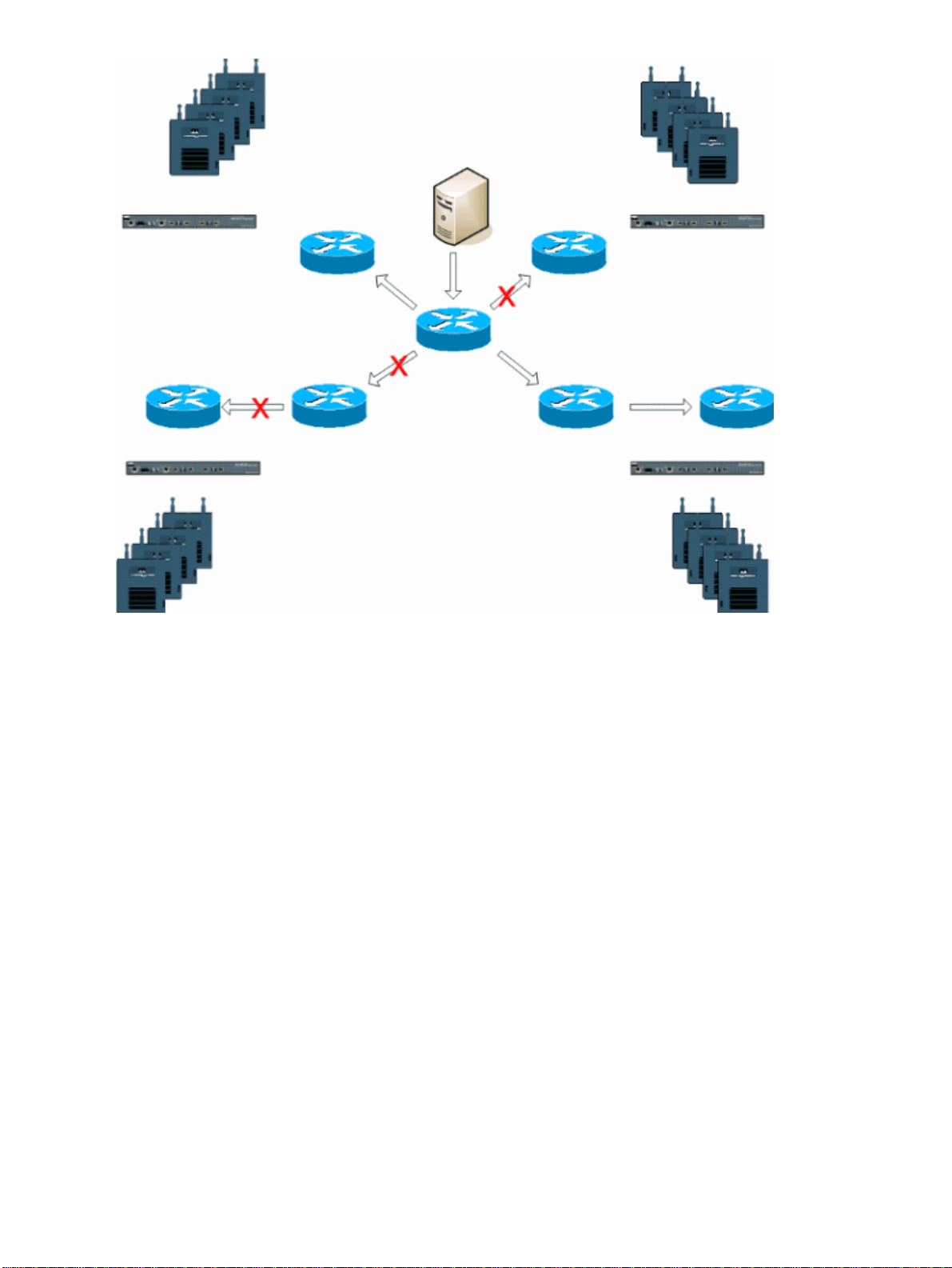
Architecture Overview
Figure 1General Multicast Forward and Prune with Lightweight Access Point Protocol (LWAPP)
Wireless
Page 5
Multicast in an LWAPP Deployment
Understanding multicast within an LWAPP deployment is necessary to deploy the Vocera broadcast function.
This document later covers the essential steps to enable multicast within the controller−based solution. There
are currently two delivery methods that the LWAPP controller uses to deliver multicast to the clients:
Unicast−Multicast•
Multicast−Multicast•
Unicast−Multicast Delivery Method
The unicast−multicast delivery method creates a copy of every multicast packet and forwards it to every
access−point. When a client sends a multicast join to the wireless LAN, the access point forwards this join
through the LWAPP tunnel to the controller. The controller bridges this multicast join onto it's directly
connected local area network connection that is the default VLAN for the associated WLAN of the client.
When an IP multicast packet arrives from the network to the controller, the controller replicates this packet
with an LWAPP header for each access point that has a client within the wireless domain who has joined this
specific group. When the source of the multicast is also a receiver within the wireless domain, this packet is
also duplicated and forwarded back to the same client who sent this packet. For Vocera badges, this is not the
preferred method of multicast delivery within the LWAPP controller solution. The unicast delivery method
works with small deployments. However, due to the considerable overhead on the Wireless LAN Controller
(WLC), this is never the recommended multicast delivery method.
Figure 2LWAPP Multicast−Unicast
Page 6
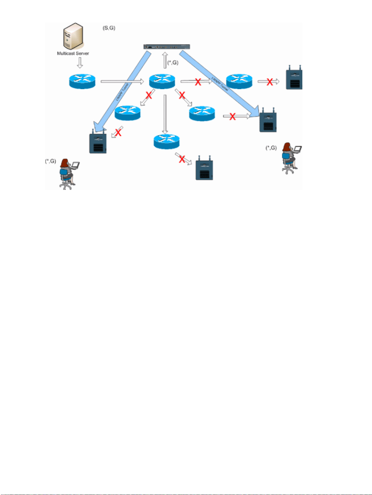
Note: If AP Group VLANs are configured, and an IGMP join is sent from a client through the controller, it is
placed on the default VLAN of the WLAN that the client is on. Therefore, the client might not receive this
multicast traffic unless the client is a member of this default broadcast domain.
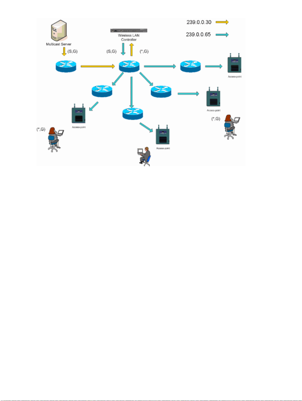
Multicast−Multicast Delivery Method
The multicast−multicast delivery method does not require the controller to replicate each multicast packet
received. The controller is configured for an un−used multicast group address that each access point becomes
a member of. With Figure 3, the multicast group defined from the WLC to the access point is 239.0.0.65.
When a client sends a multicast join to the WLAN, the access point forwards this join through the LWAPP
tunnel to the controller. The controller forwards this link−layer protocol onto it's directly connected local area
network connection that is the default VLAN for the associated WLAN of the client. The router that is local to
the controller then adds this multicast group address to that interface for forwarding ((*,G)) entry. With Figure
3, the example multicast join was sent to the multicast group 239.0.0.30. When the network now forwards
multicast traffic, the multicast address of 239.0.0.30 is forwarded to the controller. The controller then
encapsulates the multicast packet into an LWAPP multicast packet addressed to the multicast group address
(example here is 239.0.0.65) that is configured on the controller and forwarded to the network. Each access
point on the controller receives this packet as a member of the controllers multicast group. The access point
then forwards the clients/servers multicast packet (example here is 239.0.0.30) as a broadcast to the
WLAN/SSID identified within the LWAPP multicast packet.
Note: If you improperly configure your multicast network, you could end up receiving another controller's
access point multicast packets. If the first controller has to fragment this multicast packet, the fragment is
forwarded to the network and each access point must spend time to drop this fragment. If you allow all traffic
such as anything from the 224.0.0.x multicast range, this is also encapsulated and subsequently forwarded by
each access point.
Figure 3LWAPP Multicast−Multicast
Page 7
Router and Switch Multicast Configuration
This document is not a network multicast configuration guide. Refer to Configuring IP Multicast Routing for
a complete implementation story. This document covers the basics to enable multicast within your network
environment.
Enable IP Multicast Routing
IP multicast routing allows the Cisco IOS® software to forward multicast packets. The ip multicast−routing
global configuration command is required to allow multicast to function in any multicast enabled network.
The ip multicast−routing command should be enabled on all routers within your network between the
WLC(s) and their respective access points.
Router(config)#ip multicast−routing
Enable PIM on an Interface
This enables the routing interface for Internet Group Management Protocol (IGMP) operation. The Protocol
Independent Multicast (PIM) mode determines how the router populates its multicast routing table. The
example provided here does not require the rendezvous point (RP) to be known for the multicast group and
therefore sparse−dense−mode is the most desirable given the unknown nature of your multicast environment.
This is not a multicast recommendation to be configured to work although the Layer 3 interface directly
connected to your controller should be PIM enabled for multicast to function. All interfaces between your
WLC(s) and their respective access points should be enabled.
Router(config−if)#ip pim sparse−dense−mode
Page 8

Disable Switch VLAN IGMP Snooping
IGMP snooping allows a switched network with multicast enabled to limit traffic to those switchports that
have users who want multicast to be seen while pruning the multicast packets from switchports that do not
wish to see the multicast stream. In a Vocera deployment, it can be undesirable to enable CGMP or IGMP
snooping on the upstream switchport to the controller with software releases earlier than 4.0.206.0.
Roaming and multicast are not defined with a set of requirements to verify that multicast traffic can follow a
subscribed user. Although the client badge is aware that it has roamed, it does not forward another IGMP join
to make sure that the network infrastructure continues to deliver the multicast (Vocera broadcast) traffic to the
badge. At the same time, the LWAPP access point does not send a general multicast query to the roamed
client to prompt for this IGMP join. With a Layer 2 Vocera network design, disabling IGMP snooping allows
traffic to be forwarded to all members of the Vocera network no matter where they roam. This ensures that the
Vocera broadcast feature works irrespective of where the client roams. Disabling IGMP snooping globally is a
very undesirable task. It is recommended that IGMP snooping only be disabled on the Vocera VLAN that is
directly connected to each WLC.
Refer to Configuring IGMP Snooping for more information.
Router(config)#interface vlan 150
Router(config−if)#no ip igmp snooping
Multicast Enhancements in Version 4.0.206.0 and Later
With the release of 4.0.206.0, Cisco introduces an IGMP query to allow users to roam at Layer 2 by sending a
general IGMP query when this occurs. The client then responds with the IGMP group that they are a member
of and this is bridged to the wired network as described earlier in this document. When a client roams to a
controller that does not have Layer 2 connectivity, or a Layer 3 roam, synchronous routing is added for
multicast source packets. When a client, who has completed a Layer 3 roam sources a multicast packet from
the wireless network, the foreign controller encapsulates this packet in the Ethernet over IP (EoIP) in IP tunnel
to the anchor controller. The anchor controller then forwards that to the wireless clients locally associated as
well as bridge this back to the wired network where it is routed using normal multicast routing methods.
Deployment Scenarios
These three deployment scenarios cover best practices and design parameters to help with a successful Vocera
Badge deployment:
Single Controller Deployment•
Multiple Controller Layer 2 Deployment•
Multiple Controller Layer 3 Deployment•
Understanding how the Vocera Badge features interact within an LWAPP split MAC environment is essential.
With all deployment scenarios, multicast should be enabled and aggressive load balancing should be disabled.
All badge WLANs should be contained within the same broadcast domain across your entire network.
Figure 4
Page 9
Single Controller Deployment
This is the most straight forward deployment scenario. It allows you to deploy the Vocera Badge solution with
little deployment concerns. Your network must be enabled for IP multicast routing only to allow the access
points to receive the LWAPP multicast packets. If required, you can limit network multicast complexity by
configuring all routers and switches with the controllers multicast group.
With multicast configured globally on the controller, the proper SSID, security settings, and all the access
points registered the Vocera Badge solution and all its functions operates as expected. With the Vocera
Broadcast function, a user roams and the multicast traffic follows as expected. There are no extra settings
required to be configured to allow this solution to function properly.
When a Vocera Badge sends a multicast message, as it does with the Vocera Broadcast, it is forwarded to the
controller. The controller then encapsulates this multicast packet within an LWAPP multicast packet. The
network infrastructure forwards this packet to every access point that is connected to this controller. When the
access point receives this packet, it then looks at the LWAPP multicast header to determine which
WLAN/SSID it then broadcasts this packet to.
Figure 5Single Controller in Multicast−Multicast Mode
Page 10
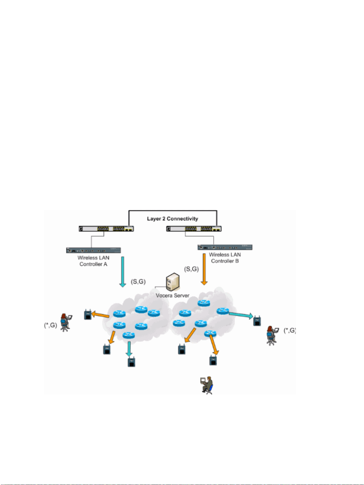
Multiple Controller Layer 2 Deployment
Multiple controllers must all have connectivity to each other via the same Layer 2 broadcast domain. Both
controllers are configured for multicast as shown, using the identical access point multicast groups on each
controller to limit fragmentation. With the assumption that this Layer 2 broadcast domain is connected via a
common switch or a common set of switches, CGMP/IGMP snooping on these switches must be disabled for
this single VLAN or run 4.0.206.0 or later WLC software. With the Vocera Broadcast function and a user
roam from an access point on one controller to an access point on a different controller, there is no mechanism
for IGMP joins to be forwarded to the new Layer 2 port for IGMP snooping to work. Without an IGMP
packet reaching the upstream CGMP or IGMP capable switch, the specified multicast group is not forwarded
to the controller and therefore is not received by the client. In some cases this might work, if a client that is
part of the same Vocera Broadcast group has already sent this IGMP packet before the roaming client roams
onto the new controller With the advantages of version 4.0.206.0, a client who roams to another controller as a
Layer 2 roam receives a general IGMP query immediately after authentication. The client should then respond
with the interested groups and the new controller is then bridged this to the locally connected switch. This
allows the advantages of IGMP and CGMP on your upstream switches.
You can create additional badge SSIDs and Layer 2 domains for separate badge networks as long as your
network is configured to pass multicast traffic appropriately. Also, each Vocera Layer 2 broadcast domain
created must exist everywhere a controller is connected to the network so as not to break multicast.
Figure 6Multiple Controller Layer 2 Deployment
Multiple Controller Layer 3 Deployment
The Layer 3 roaming deployment strategy should only be used with controller−to−controller roaming with
WLC software release 4.0.206.0 or later. If a client that has been connected to the Vocera broadcast group and
receives the appropriate multicast stream and roams to another controller as a Layer 3 roam with the LWAPP
Layer 3 roaming configured, it is queried for interested multicast groups. The client, when sourcing to the
same Vocera broadcast group, has these packets delivered to the anchor controller through the EoIP tunnel
Page 11

and has these packets routed through normal multicast routing methods.
Figure 7Multiple Controller Layer 3 Deployment
VoWLAN Deployments: Ciscos Reccommendations
Wireless IP Telephony networks require careful RF planning. A thorough voice site survey is often required
to determine the proper levels of wireless coverage and to identify sources of interference. Access point
placement and antenna selection choices can be greatly eased with the help of the results of a valid voice site
survey. The most important consideration is the transmit power of the wireless phone. Ideally the phone learns
the transmit power of the access point and adjust its transmit power to that of the access point.
Although the majority of the wireless networks today are deployed after an extensive RF site survey, they are
done with keeping data service in mind as well. VoWLAN phones are likely to have different roaming
characteristics and different coverage requirements than those of a typical WLAN adapter for a mobile client
such as a laptop. Therefore, an additional site survey for voice is often recommended to prepare for the
performance requirements of multiple VoWLAN clients. This additional survey gives the opportunity to tune
the access points to ensure that the VoWLAN phones have enough RF coverage and bandwidth to provide
proper voice quality.
For additional information on RF design considerations, refer to the chapter on WLAN Radio Frequency (RF)
Design Considerations in the Cisco Wireless LAN Design Guide, available at http://cisco.com/go/srnd.
Recommendations for Multi−Floor Buildings, Hospitals, and Warehouses
Consider the factors listed in this section when you survey multi−floor buildings, hospitals, and warehouses.
Construction Methods and Materials
Many aspects of the building construction are unknown or hidden from the site survey, so you might have to
acquire that information from other sources (such as architectural drawings). Some examples of typical
construction methods and materials that affect the range and coverage area of access points include metallic
film on window glass, leaded glass, steel−studded walls, cement floors and walls with steel reinforcement,
foil−backed insulation, stairwells and elevator shafts, plumbing pipes and fixtures, and many others.
Page 12

Inventory
Various types of inventory can affect RF range, particularly those with high steel or water content. Some
items to watch for include cardboard boxes, pet food, paint, petroleum products, engine parts, and so forth.
Levels of Inventory
Make sure you perform a site survey at peak inventory levels or at times of highest activity. A warehouse at a
50% stocking level has a very different RF footprint than the same warehouse at an inventory level of 100%.
Activity Levels
Similarly, an office area after hours (without people) has a different RF footprint than the same area full of
people during the day. Although many parts of the site survey can be conducted without full occupation, it is
essential to conduct the site survey verification and tweak key values during a time when the location is
occupied. The higher the utilization requirements and the density of users, the more important it is to have a
well designed diversity solution. When more users are present, more signals are received on each user's
device. Additional signals cause more contention, more null points, and more multipath distortion. Diversity
on the access point (antennas) helps minimize these conditions.
Multi−Floor Buildings
Keep in mind these guidelines when you conduct a site survey for a typical office building:
Elevator shafts block and reflect RF signals.•
Supply rooms with inventory absorb signals.•
Interior offices with hard walls absorb RF signals.•
Break rooms (kitchens) can produce 2.4 GHz interference through the use of microwave ovens.•
Test labs can produce 2.4 GHz or 5 GHz interference, creating multipath distortion and RF shadows.•
Cubicles tend to absorb and block signals.•
Conference rooms require high access point coverage because they are areas of high utilization.•
Extra precaution must be administered when you survey multi−floor facilities. Access points on different
floors can interfere with each other as easily as access points located on the same floor. It is possible to use
this behavior to your advantage during a survey. Using higher−gain antennas, it might be possible to penetrate
floors and ceilings and provide coverage to floors above as well as below the floor where the access point is
mounted. Be careful not to overlap channels between access points on different floors or access points on the
same floor. In multi−tenant buildings, there might be security concerns that require the use of lower
transmission powers and lower gain antennas to keep signals out of neighboring offices.
Hospitals
The survey process for a hospital is much the same as that for an enterprise, but the layout of a hospital
facility tends to differ in these ways:
Hospital buildings tend to go through many reconstruction projects and additions. Each additional
•
construction is likely to have different construction materials with different levels of attenuation.
Signal penetration through walls and floors in the patient areas is typically minimal, which helps
•
create micro−cells and multipath variations.
The need for bandwidth increases with the increasing use of WLAN ultrasound equipment and other
•
portable imaging applications. The need for bandwidth increases with the addition of wireless voice
as well.
Healthcare cells are small, and seamless roaming is essential, especially with voice applications.•
Cell overlap can be high, and so can channel reuse.•
Page 13

Hospitals can have several types of wireless networks installed. This includes 2.4 GHz non−802.11
•
equipment. This equipment can cause contention with other 2.4 GHz networks.
Wall−mounted diversity patch antennas and ceiling−mounted diversity omni−directional antennas are
•
popular, but keep in mind that diversity is required.
Warehouses
Warehouses have large open areas that often contain high storage racks. Many times, these racks reach almost
to the ceiling, where access points are typically placed. Such storage racks can limit the area that the access
point can cover. In these cases, consider placing access points on other locations besides the ceiling, such as
side walls and cement pillars. Also consider these factors when you survey a warehouse:
Inventory levels affect the number of access points needed. Test coverage with two or three access
•
points in estimated placement locations.
Unexpected cell overlaps are likely because of multipath variations. The quality of the signal varies
•
more than the strength of that signal. Clients might associate and operate better with access points
farther away than with nearby access points.
During a survey, access points and antennas usually do not have an antenna cable connecting them.
•
But in a production environment, the access point and antenna might require antenna cables. All
antenna cables introduce signal loss. The most accurate survey includes the type of antenna to be
installed and the length of cable to be installed. A good tool to use to simulate the cable and its loss is
an attenuator in a survey kit.
Surveying a manufacturing facility is similar to surveying a warehouse, except that there might be many more
sources of RF interference in a manufacturing facility. In addition, the applications in a manufacturing facility
usually require more bandwidth than those of a warehouse. These applications can include video imaging and
wireless voice. Multipath distortion is likely to be the greatest performance problem in a manufacturing
facility.
Security Mechanisms Supported
In addition to static WEP and Cisco LEAP for authentication and data encryption, the Vocera Badges also
support WPA−PEAP (MS−CHAP v2)/WPA2−PSK.
LEAP Considerations
LEAP allows devices to be authenticated mutually (badge−to−access point and access point−to−badge) based
on a user name and password. Upon authentication, a dynamic key is used between the phone and the access
point to encrypt traffic. However, the ASLEAP dictionary attack should be considered when you decide to use
LEAP as your security solution:
Refer to Dictionary Attack on Cisco LEAP Vulnerability for more information.
If LEAP is used, a LEAP−compliant RADIUS server, such as the Cisco Access Control Server (ACS), is
required to provide access to the user database. The Cisco ACS can either store the user name and password
database locally, or it can access that information from an external Microsoft Windows NT directory. When
using LEAP, ensure that strong passwords are used on all wireless devices. Strong passwords are defined as
being between 10 and 12 characters long and can include both uppercase and lowercase characters as well as
the special characters.
Because all the badges use the same password and it is stored within the badge, Cisco recommends that you
use different user names and passwords on data clients and wireless voice clients. This practice helps with
tracking and troubleshooting as well as security. Although it is a valid configuration option to use an external
Page 14

(off−ACS) database to store the user names and passwords for the badges, Cisco does not recommend this
practice. Because the ACS must be queried whenever the badge roams between access points, the
unpredictable delay to access an off−ACS database could cause excessive delay and poor voice quality.
Wireless Network Infrastructure
The wireless IP Telephony network, just like a wired IP Telephony network, requires careful planning for
VLAN configuration, network sizing, multicast transport, and equipment choices. For both wired and wireless
IP Telephony networks, separate voice and data VLANs is often the most effective way of suggested
deployment to ensure sufficient network bandwidth and ease of troubleshooting.
Voice, Data and Vocera VLANs
VLANs provide a mechanism for segmenting networks into one or more broadcast domains. VLANs are
especially important for IP Telephony networks, where the typical recommendation is to separate voice and
data traffic into different Layer 2 domains. Cisco recommends that you configure separate VLANs for the
Vocera Badges from other voice and data traffic: a native VLAN for access point management traffic, data
VLAN for data traffic, a voice or auxiliary VLAN for voice traffic, and a VLAN for the Vocera Badges. A
separate voice VLAN enables the network to take advantage of Layer 2 marking and provides priority
queuing at the Layer 2 access switch port. This ensures that appropriate QoS is provided for various classes of
traffic and helps to resolve addressing issues such as IP addressing, security, and network dimensioning. The
Vocera Badges use a broadcast feature that utilizes multicast to deliver. This common VLAN ensures that
when a badge roams between controllers, it remains part of the multicast group. This last process is discussed
in detail when multicast is addressed later in this document.
Network Sizing
IP Telephony network sizing is essential to ensure that adequate bandwidth and resources are available to
meet the demands presented by the presence of voice traffic. In addition to the usual IP Telephony design
guidelines for sizing components such as PSTN gateway ports, transcoders, WAN bandwidth, and so forth,
also consider these 802.11b issues when you size your wireless IP Telephony network. The Vocera Badges
are a specialized application that stretch the number of wired clients beyond our typical deployment
recommendations.
Number of 802.11b Devices per Access Point
Cisco recommends that you have no more than 15 to 25 802.11b devices per access point.
Number of Active Calls per Access Point
Vocera uses two different codecs based on if it is a badge−to−badge (proprietary low−bit rate codec) call or a
badge−to−phone (G.711 codec) call. This table shows a percentage of available bandwidth by data rates and
gives you a clearer picture of the expected throughput:
Call Process 1
Badge−to−Phone (G.711)
Badge−to−Badge
(Proprietary Low−bit rate
codec)
Mbps2Mbps
20.7% 11.8% 6.3% 4.7%
9.4% 6.1% 4.2% 3.6%
5.5
Mbps11Mbps
Page 15

Switch Recommendations
Note: If you use a Cisco Catalyst 4000 Series Switch as the main router in the network, ensure that it contains,
at a minimum, either a Supervisor Engine 2+ (SUP2+) or Supervisor Engine 3 (SUP3) module. The SUP1 or
SUP2 module can cause roaming delays, as can the Cisco Catalyst 2948G, 2980G, 2980G−A, 4912, and
2948G−GE−TX switches.
You can create a switch port template for use when you configure any switch port for connection to an access
point. This template should add all the baseline security and resiliency features of the standard desktop
template. In addition, when you attach the access point to a Cisco Catalyst 3750 Switch, you can optimize the
performance of the access point by using Multilayer Switching (MLS) QoS commands to limit the port rate
and to map Class of Service (CoS) to Differentiated Services Code Point (DSCP) settings.
Any traffic that is not required by WLAN clients should not be sent to an access point. A template should be
designed in such a way that helps create a secure and resilient network connection with these features:
Return Port Configurations to default Prevents configuration conflicts by clearing any pre−existing
•
port configurations.
Disable Dynamic Trunking Protocol (DTP) Disables dynamic trunking, which is not needed for
•
connection to an access point.
Disable Port Aggregation Protocol (PagP) PagP is enabled by default but is not needed for
•
user−facing ports.
Enable Port FastAllows a switch to quickly resume forwarding traffic if a spanning tree link goes
•
down.
Configure Wireless VLANCreates a unique wireless VLAN that isolates wireless traffic from other
•
data, voice, and management VLANs. This isolates traffic and ensures greater control of traffic.
Enable Quality of Service (QoS); do not trust port (mark down to 0)Ensures appropriate treatment of
•
high−priority traffic, including softphones, and prevents users from consuming excessive bandwidth
by reconfiguring their PCs.
WS−C3750−48PS−S Inline Power Switches can be used to provide power to access points that are capable of
receiving inline power.
The Catalyst 6500 allows you to forward packets at line rate with all the features described here as well as
integrating numerous service modules. The Wireless Service Module (WiSM) allows you to have two
controllers each with the capability to control 150 access points each. With up to five WiSMs per chassis, this
allows you to control over 1500 access points that support 50,000 clients within a single high performance
switching architecture.
Deployments and Configuration
Badge Configuration
The Vocera Badge Configuration Utility (BCU) and the configuration of the badge can introduce roaming and
latency into your environment if done incorrectly. Using the BCU and the Badge Properties Editor (BPE),
verify these settings (see Figure 8):
Subnet Roaming is disabled.•
Scan Default Channels (1,6,11) is checked.•
Broadcast Uses IGMP is enabled.•
Roaming Policy is set to 2 or higher.•
Figure 8Vocera BCU Advanced Tab
Page 16

When Subnet Roaming is checked, it instructs the badge to request a new IP address after each roam. In the
LWAPP environment, the infrastructure helps maintain client connectivity at Layer 3. When a voice client
must wait for the DHCP server to respond before it is able to send or receive packets, delay and jitter are
introduced. If Scan Default Channels (1,6,11) is not checked, the badge scans all 802.11b channels when the
badge looks to roam. This prevents the forwarding of packets and seamless roaming.
Tune AutoRF for Your Environment
As described in the Recommendations section of this document, it is important to understand that each site
has it's own RF characteristics. AutoRF or Radio Resource Management (RRM) might need to be tuned, with
the understanding that each site is different and AutoRF/RRM should be tuned for your environment.
Before you adjust AutoRF, refer to Radio Resource Management under Unified Wireless Networks for more
information.
RRM allows you to adjust the transmit power of each access point, by adjusting how strong each access point
hears its third strongest neighbor. This value can only be adjusted from the CLI using the config advanced
802.11b tx−power−thresh command as described in Tx Power Level Assignment Settings.
Before you adjust AutoRF, walk the deployment site using the Vocera badge as worn by the end user and use
a site survey tool in order to gain a strong understanding of how the badge roams and at what power each
Page 17

access point is seen. Once this is complete and it is determined that adjusting this value is required, begin with
a value of Ÿ1 dBm for the Transmit Power Control algorithm. Use this CLI parameter:
config advanced 802.11b tx−power−thresh −71
Allow the network to work through this adjustment with a minimum of 30 minutes to an hour before you
observe any changes. Once the network is given a sufficient amount of time, walk the site using the same
survey tool and badges again. Observe the same roaming characteristics and access point power. The goal
here is to attempt to have the badges roam at or before the next access point to get the best possible signal to
noise ratio.
How do I know if the tranmit power is too hot or too cold?
•
Determining whether you have your transmit power threshold too high or too low requires a good
understanding of your environment. If you have walked your entire deployment area (where you
expect your Vocera badges to function), you should know where your access points are located as
well as experience the roaming behavior of the badge.
What do I do if my transmit power is too hot?
•
The Vocera Badge roams based solely on the signal strength rather than signal quality. If the Vocera
Badge does not roam after it passes several access points while engaged in the welcome tutorial or the
test tone, the badge is considered to be sticky. If this behavior is indicative of the entire campus
deployment area, then your transmit power threshold is too hot and should be backed down. If only
one or two isolated areas show this behavior and the rest of the deployment area shows more idealistic
roaming characteristics this is not an indication that your network is running too hot.
What do I do if my transmit power is too cold?
•
The default transmit threshold should almost never provide you a deployment area where your
network runs too cold. If the transmit power threshold is adjusted down, and walking the halls with
the Vocera Badge provides you with an environment where the badge roams well, but loses
connectivity and/or dead/spotty coverage, then your network might have been tuned too low. If this is
not characteristic of your entire network but isolated to one or two areas, then it is more indicative of
a coverage hole rather than a network−wide problem.
Isolated Behavior
•
If you find that in one or two areas, the badge sticks to an access point rather than roaming in an
idealistic manner, examine this area.
How is this area different from the rest of the campus?♦
If this/these areas are near building exits or areas under construction, could coverage hole
♦
detection be forcing these access points to raise the power?
Look at the WLC log file and access point neighbor lists to help determine why such an
♦
anomaly could occur.
If you find that in one or more isolated areas, the badge experiences dead or spotty coverage, then you
need to examine these areas separately.
Is this area near an elevator shaft, radiology, or a break room?♦
These areas might be better suited by the installation or better placement of an access point to
♦
allow for better voice coverage.
In both cases, it is always advisable to understand that you are working in an unlicensed radio
spectrum and idealistic behavior might not ever be achievable. This could happen when you are
situated next to a radio transmission tower or device, a television transmitter or possibly a non−802.11
2.4 GHz repair facility (wireless phones, and so forth).
Page 18

Wireless Network Infrastructure Configuration
The Cisco Unified Wireless Network design and deployment guide should be followed for the overall
configuration of your WLC(s). This section provides additional recommendations specific to Vocera®
Communication Badges.
Note: Changes are left unsaved if you do not press the Apply button before you move to the next step.
Complete these steps under the Controller top−level menu:
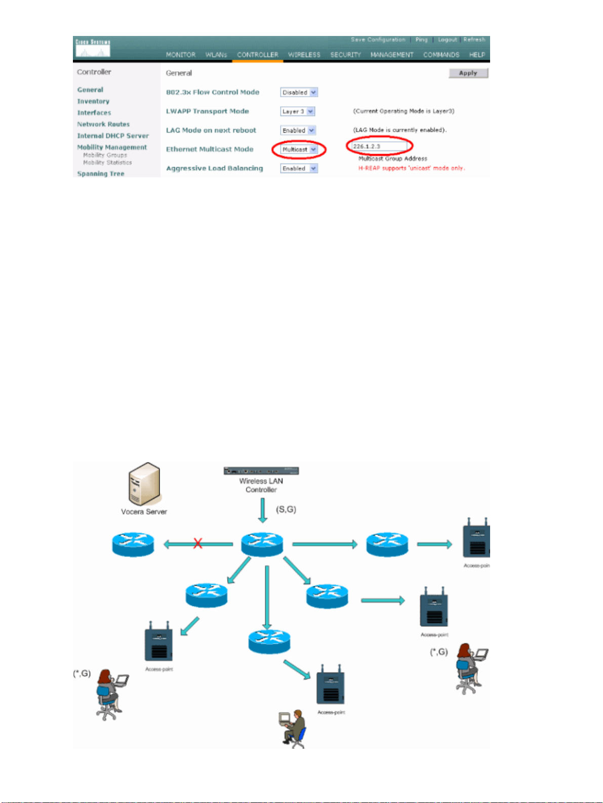
Change Ethernet Multicast Mode to Multicast.1.
Set the Multicast Group Address to 239.0.0.255 (or some other unused multicast group address).2.
Set the Default Mobility Domain Name and RF−Network Name to your network design.3.
Disable Aggressive Load Balancing.
4.
Figure 9General WLC Configuration
Create Interfaces
Click Controller > Interfaces.
Note: Your VLAN and IP address varies. The screen shots here provide sample addressing which should not
be directly followed.
Page 19

Figure 10List of WLC Interfaces
Create the Vocera Voice Interface
Complete these steps:
Click New.1.
Enter a tag name representative of your Vocera VoWLAN network in the Interface Name field.2.
Enter the VLAN number of that VoWLAN network in the VLAN ID field.3.
Click Apply and then click Edit in order to edit the interface that you just created.4.
Enter the IP addressing for this interface that is in the range of the VLAN and other related
5.
information.
Click Apply.6.
Wireless−Specific Configuration
For a WLAN that has only Vocera Badges, this configuration provides sample settings that best support the
Vocera Broadcast application.
The DTIM Period is 1.•
Support for 802.11g is disabled. Only the 802.11b data rate of 11 Mpbs is Mandatory.•
Short preamble is disabled.•
DTPC is disabled.•
Figure 11802.11b/g Configuration
Page 20

WLAN Configuration
Complete these steps:
Update the Radio Policy field to a value that best fits you needs.1.
Change Admin Status to Enabled.2.
Set Session Timeout to 1800.3.
Set Quality of Service to Platinum.4.
Set Broadcast SSID to Enabled.5.
Set the Interface Name to the interface created for the Vocera Communication Badges.6.
Set the security options to match your corporate policies.
7.
Figure 12WLAN Configuration
Page 21

Configure Access Point Detail
Complete these steps:
Click Detail.1.
Configure the AP Name.2.
Ensure that the access point is configured for DHCP.3.
Ensure that Admin Status is Enabled.4.
AP Mod should be set to local.5.
Enter the location of the access point.6.
Enter the controller name that the access point belongs to. The controller name can be found on the
7.
Monitor page.
Click Apply.
8.
Figure 13AP Detail
Page 22

Configure the 802.11b/g Radio
Complete these steps:
Click Wireless located at the top of the WLC and verify that all access points under Admin Status are
1.
set to Enable.
Figure 14
Click Network (located near 802.11b/g).2.
Click AutoRF.3.
Use AutoRF to create a complete coverage with non−overlapping RF channel and a transmit power.
4.
In order to do this, select Automatic for both RF Channel Assignment and Tx Power Level
Assignment.
Figure 15
Page 23

Click Apply.5.
Click Save Configuration and see the Tune AutoRF for Your Environment section of this document.6.
Choose Wireless > Access Points > 802.11b/g Radios.
7.
Figure 16
Wireless IP Telephony Verification
After you conduct an RF site survey and configure the access points and the phones, it is crucial to conduct
verification tests to ensure that everything works as desired. These tests should be performed at all of these
locations:
Page 24

The primary area of each access point cell (where the badges are most likely to connect to that
•
particular access point).
Any location where there might be high call volume.•
Locations where usage might be infrequent but coverage still has to be certified (for example,
•
stairwells, restrooms, and so forth).
At the fringes of the access point's coverage area.•
" These tests can be performed in parallel or series. If performed in parallel, ensure that phones are
•
powered off between testing points to test full association, authentication, and registration at each
location. Roaming and load tests must be the final tests.
Association, Authentication, and Registration
This section explains how to verify that the badge associates, authenticates, and registers properly.
At multiple points throughout the environment, power−up the badges and verify association with the
•
access point. If the badge does not associate with the access point, perform these checks:
Check the badge configuration to ensure proper SSID, authentication type, and so forth.♦
Check the WLC configuration to ensure proper SSID, authentication type, radio channels, and
♦
so forth.
Check your site survey to ensure the location has adequate RF coverage.♦
At multiple points throughout the environment, ensure that the phone authenticates through the access
•
point successfully. If the client does not authenticate, check either the WEP key or the LEAP
username and password on the badges. Also, check the username and password on the AAA server by
using a wireless laptop with identical credentials.
At multiple points throughout the environment, ensure that the badges register with the Vocera
•
Communication Server. If the client does not register, perform these checks:
Verify that the badge has the correct IP address, subnet mask, primary gateway, primary
♦
TFTP, primary/secondary and DNS.
Stationary voice calls:
•
At multiple points throughout the environment, while you stand still, make a call to another
♦
badge and conduct 60 to 120−second voice tests to check voice quality. If the voice quality is
unacceptable, move one badge to a better location and test again. Is the voice quality
acceptable? If not, check your wireless coverage.
If the telephony server is configured, at multiple points throughout the environment, stand
♦
still and make a call to a wired phone and conduct 60 to 120−second voice tests to check
voice quality. If the voice quality is unacceptable, ask if you make a call using the wired
phone. Is the voice quality acceptable? If not, verify the wired network design against the
guidelines.
Use the site survey tools to verify that there is no more than one access point per RF channel from that
•
location with a signal strength (received signal strength indicator [RSSI]) greater than 35. If there are
two access points present on the same channel, ensure that the signal−to−noise ratio (SNR) is as high
as possible to minimize interference. For instance, if the stronger access point has an RSSI of 35,
ideally the weaker access point should have an RSSI of less than 20. In order to achieve this goal, you
might have to reduce one access point's transmit power or move the access point.
Check the QoS settings on the access point to confirm proper recommended settings.•
Roaming badge calls:
•
If the telephony server is not available, initiate the Vocera Tutorial with the command Begin
♦
Tutorial.
Page 25

OR
If the telephony server is available, initiate a call with a stationary device to the badge.♦
Continually check voice quality while you traverse the total wireless coverage area. If the
♦
voice quality is insufficient, perform these tasks:
Listen for all unacceptable changes in voice quality and take note of the location and radio
♦
values on your laptop and CQ values from the badge.
Watch and listen for the badge to roam to the next access point.♦
Note the other available access points in the site survey to check coverage and interference.♦
Make adjustments to access point placement and settings to fine−tune the WLAN, and perform these
•
checks to ensure voice quality:
Use the site survey tools and verify that there is no more than one access point per channel
♦
with an RSSI value greater than 35 in any given location. Ideally, all other access points on
the same channel should have RSSI values as low as possible (preferably less than 20). At the
border of the coverage area where the RSSI is 35, the RSSI for all other access points on the
same channel should ideally be less than 20.
Use the site survey tools to verify that there are at least two access points (total, on separate
♦
channels) visible in all location with sufficient signal strength.
Check that the access points in a given roaming area are all on a Layer 2 network.♦
Common Roaming Issues
These roaming issues can occur:
The badge does not roam when placed directly under the access point.•
The badge is most likely not reaching the roaming differential thresholds for the received signal
•
strength indicator (RSSI) and channel utilization (CU). Adjust the Transmit Power Threshold form the
WLC.
The badge does not receive beacons or probe responses from the access point.•
The badge roams too slowly.•
The Badge Loses Connection to the Network or Voice Service is Lost
when Roaming
Check authentication for a possible WEP mismatch.•
The badge does not send out IGMP joins or the network sends IGMP queries during a roam.
•
Therefore, the Vocera broadcast function fails during a Layer 2/Layer 3 roam.
The badge is capable of seamless Layer 2 roaming only (unless a Layer 3 mobility mechanism is
•
configured). Ensure that the new WLC is not serving a different IP subnet.
Verify that the associated access point/controller has IP connectivity to the Vocera Communication
•
Server.
Check the RF signal strength and badge CQ values.•
Badge Loses Voice Quality while Roaming
Check for low RSSI on the destination access point.•
Channel overlap might be insufficient. The badge must have time to hand off the call smoothly before
•
it loses its signal with the original access point.
The signal from the original access point might be lost.•
Page 26

Audio Problems
There are a few common configuration errors that can cause some easily resolved audio issues. If possible,
check audio problems against a stationary (reference) badge to help narrow the problem to a wireless issue.
Common audio problems include:
One−sided Audio•
Choppy or Robotic Audio•
Registration and Authentication Problems•
One−sided Audio
This problem can occur in the fringe areas of an access point, where a signal might be too weak on
•
either the badge side or the access point side. Matching the power settings on the access point to the
badge (20 mW), when possible, can fix this problem. This problem is most common when the
variation between the access point setting and the badge setting is large (for example, 100 mW on the
access point and 28 mW on the badge).
Check the gateway and IP routing for voice quality.•
Check to see if a firewall or NAT is in the path of the proprietary UDP packets. By default, firewalls
•
and NATs cause one−way audio or no audio. Cisco IOS® and PIX NATs and firewalls have the
ability to modify those connections so that two−way audio can flow.
If you use Layer 3 mobility, your network could be blocking upstream traffic with Unicast
♦
Reverse Path Forwarding (uRPF) checks.
One−way audio can occur if ARP caching is not configured on the WLC.•
Choppy or Robotic Audio
A common reason for choppy or robotic audio is when a microwave operates nearby. Microwaves
•
start at channel 9 and can extend from channels 6 to 14.
Check for 2.4 Ghz wireless phones and other nurse call wireless devices using tools like Cognio.•
Registration and Authentication Problems
When you encounter problems with authentication, perform these checks:
Check SSIDs to make sure they match on the badge and the access point (or network). Also be sure
•
the network has a route to the Vocera server.
Check the WEP keys to make sure they match. It is a good idea to re−enter them on the Badge
•
Configuration Utility (BCU) and reprogram the badge, because it is easy to make a typing error when
you enter a WEP key or password.
These messages or symptoms can occur:
Cannot Support All Requested CapabilitiesThis is most likely an encryption mismatch between the
•
access point and the client.
Authentication Failed / No AP FoundEnsure authentication types match on the access point and the
•
client.
No Service IP Config FailedIf you use static WEP, ensure the keys are configured correctly.
•
Ensure other clients can receive DHCP using the same SSID.
De−authenticate all TKIP clients from APThis problem happens when the access point detects two
•
MIC errors within 60 seconds. This countermeasure keeps all TKIP clients from re−authenticating for
60 seconds.
Page 27

Re−authentication / Session TimeoutIf configured, a session timeout triggers a re−authentication
•
which causes gaps in the voice stream (300 ms + WAN delay for 802.1x authentication).
Appendix A
AP and Antenna Placement
This section gives examples of both proper and improper placement of access points (APs) and antennas.
Figure 17 shows improper placement of an access point and antennas close to an I−beam, which creates
distorted signal patterns. An RF null point is created by the crossing of signal waves, and multipath distortion
is created when signal waves are reflected. This placement results in very little coverage behind the access
point and reduced signal quality in front of the access point.
Figure 17Improper Placement of Antennas Near an I−Beam
Figure 18 shows the signal propagation changes or distortions caused by an I−beam. The I−beam creates
many reflections from both received packets and transmitted packets. The reflected signals result in very poor
signal quality because of null points and multipath interference. However, the signal strength is high because
the access point antennas are so close to the I−beam.
Figure 18Signal Distortions Caused by Placing the Antennas Too Close to an I−Beam
The access point and antenna placement in Figure 19 is better because it is away from the I−beams and there
are fewer reflected signals, fewer null points, and less multipath interference. This placement is still not
perfect because the Ethernet cable should not be coiled up so close to the antenna. Also, the access point could
be turned with the 2.4GHz antennas pointed to the floor. This provides better coverage directly below the
access point. There are no users above the access point.
Figure 19Access Point and Antennas Mounted on a Wall, Away from I−Beams
Page 28

Figure 20 shows the signal propagation caused by the wall on which the access point is mounted.
Figure 20Signal Reflection Caused by a Wall
The preceding examples also apply when you place access points and antennas in or near the ceiling in a
standard Enterprise environment. If there are metal air ducts, elevator shafts, or other physical barriers that
can cause signal reflection or multipath interference, Cisco highly recommends that you move the antennas
away from those barriers. In the case of the elevator, move the antenna a few feet away in order to help
eliminate the signal reflection and distortion. The same is true with air ducts in the ceiling.
A survey conducted without sending and receiving packets is not sufficient. The I−beam example shows the
creation of null points that can result from packets that have CRC errors. Voice packets with CRC errors are
missed packets that adversely affect voice quality. In this example, those packets could be above the noise
floor measured by a survey tool. Therefore, it is very important that the site survey not only measures signal
levels but also generates packets and then reports packet errors.
Figure 21 shows a Cisco AP1200 properly mounted to a ceiling T−bar, with the antennas in an
omni−directional position.
Figure 21Cisco AP1200 Mounted to a Ceiling
Page 29

Figure 22 shows a Cisco Aironet 5959 omni−directional diversity antenna properly mounted to a ceiling
T−bar. In this case, the Cisco AP1200 is mounted above the ceiling tile.
Figure 22Cisco Aironet 5959 Antenna Mounted to a Ceiling
Figure 23 shows a Cisco AP1200 properly mounted to a wall.
Figure 23Cisco AP1200 Mounted to a Wall
Figure 24 shows the Cisco Aironet 2012 diversity patch antenna mounted to a wall. In this case, the Cisco
AP1200 is mounted above the ceiling tile.
Figure 24Cisco Aironet 2012 Antenna Mounted to a Wall
Page 30

For areas where user traffic is high (such as office spaces, schools, retail stores, and hospitals), Cisco
recommends that you place the access point out of sight and place unobtrusive antennas below the ceiling.
Separation for non−diversity antennas should not exceed 18 inches.
Interference and Multipath Distortion
The throughput performance of the WLAN network is affected by unusable signals. WLAN interference can
be generated by microwave ovens, 2.4 GHz cordless phones, Bluetooth devices, or other electronic equipment
operating in the 2.4 GHz band. Interference also typically comes from other access points and client devices
that belong in the WLAN but that are far enough away so that their signal is weakened or has become
corrupted. Access points that are not part of the network infrastructure can also cause WLAN interference and
are identified as rogue access points.
Interference and multipath distortion cause the transmitted signal to fluctuate. Interference decreases the
signal−to−noise ratio (SNR) for a particular data rate. Packet retry counts go up in an area where interference
and/or multipath distortion are high. Interference is also referred to as noise level or noise floor. The strength
of the received signal from its associated access point must be high enough above the receiver's noise level to
be decoded correctly. This level of strength is referred to as the signal−to−noise ratio, or SNR. The ideal SNR
for the Vocera Badge is 25 dB. For example, if the noise floor is 95 decibels per milliwatt (dBm) and the
received signal at the phone is 70 dBm, then the signal−to−noise ratio is 25 dB. (See Figure 25.)
Figure 25Signal−to−Noise Ratio (SNR)
When you change the type and location of the antenna, it can reduce multipath distortion and interference.
Antenna gain adds to the system gain and can reduce interference if the interfering transmitter is not directly
in front of the directional antenna.
Page 31

While directional antennas can be of great value for certain indoor applications, the vast majority of indoor
installations use omni−directional antennas. Directionality should be strictly determined by a correct and
proper site survey. Whether you use an omni−directional or patch antenna, indoor environments require
diversity antennas to mitigate multipath distortion. The Cisco Aironet Series Access Point radios allow for
diversity support.
Signal Attenuation
Signal attenuation or signal loss occurs even as the signal passes through air. The loss of signal strength is
more pronounced as the signal passes through different objects. A transmit power of 20 mW is equivalent to
13 dBm. Therefore, if the transmitted power at the entry point of a plasterboard wall is at 13 dBm, the signal
strength is reduced to 10 dBm when exiting that wall. This table shows the likely loss in signal strength
caused by various types of objects.
Signal Attenuation Caused By Various Types of Objects
Object in Signal Path
Plasterboard wall
Glass wall with metal frame
Cinder block wall
Office window
Metal door
Metal door in brick wall
Human body
Each site surveyed has different levels of multipath distortion, signal loses, and signal noise. Hospitals are
typically the most challenging environment to survey due to high multipath distortion, signal losses and signal
noise. Hospitals take longer to survey, require a denser population of access points, and require higher
performance standards. Manufacturing and shop floors are the next hardest to survey. These sites generally
have metal siding and many metal objects on the floor, which result in reflected signals that recreate multipath
distortion. Office buildings and hospitality sites generally have high signal attenuation but a lesser degree of
multipath distortion.
Signal Attenuation through Object
3 dB
6 dB
4 dB
3 dB
6 dB
12 dB
3 dB
NetPro Discussion Forums − Featured Conversations
Networking Professionals Connection is a forum for networking professionals to share questions, suggestions,
and information about networking solutions, products, and technologies. The featured links are some of the
most recent conversations available in this technology.
NetPro Discussion Forums − Featured Conversations for Wireless
Wireless − Mobility: WLAN Radio Standards
Wireless − Mobility: Security and Network Management
Wireless − Mobility: Getting Started with Wireless
Wireless − Mobility: General
Page 32

Related Information
Deploying Cisco 440X Series Wireless LAN Controllers•
Solution Reference Network Design•
Vocera Communications System Specifications•
Technical Support & Documentation − Cisco Systems•
All contents are Copyright © 2006−2007 Cisco Systems, Inc. All rights reserved. Important Notices and Privacy Statement.
Updated: Sep 18, 2007 Document ID: 71642
 Loading...