

Page 1

Firepower 7000 and 8000 Series Installation Guide
Vers ion 6. 0
November 5, 2015
Cisco Systems, Inc.
www.cisco.com
Cisco has more than 200 offices worldwide.
Addresses, phone numbers, and fax numbers
are listed on the Cisco website at
www.cisco.com/go/offices.
Page 2

THE SPECIFICATIONS AND INFORMATION REGARDING THE PRODUCTS IN THIS MANUAL ARE SUBJECT TO CHANGE WITHOUT NOTICE. ALL
STATEMENTS, INFORMATION, AND RECOMMENDATIONS IN THIS MANUAL ARE BELIEVED TO BE ACCURATE BUT ARE PRESENTED WITHOUT
WARRANTY OF ANY KIND, EXPRESS OR IMPLIED. USERS MUST TAKE FULL RESPONSIBILITY FOR THEIR APPLICATION OF ANY PRODUCTS.
THE SOFTWARE LICENSE AND LIMITED WARRANTY FOR THE ACCOMPANYING PRODUCT ARE SET FORTH IN THE INFORMATION PACKET THAT
SHIPPED WITH THE PRODUCT AND ARE INCORPORATED HEREIN BY THIS REFERENCE. IF YOU ARE UNABLE TO LOCATE THE SOFTWARE LICENSE
OR LIMITED WARRANTY, CONTACT YOUR CISCO REPRESENTATIVE FOR A COPY.
The Cisco implementation of TCP header compression is an adaptation of a program developed by the University of California, Berkeley (UCB) as part of UCB’s public
domain version of the UNIX operating system. All rights reserved. Copyright © 1981, Regents of the University of California.
NOTWITHSTANDING ANY OTHER WARRANTY HEREIN, ALL DOCUMENT FILES AND SOFTWARE OF THESE SUPPLIERS ARE PROVIDED “AS IS” WITH
ALL FAULTS. CISCO AND THE ABOVE-NAMED SUPPLIERS DISCLAIM ALL WARRANTIES, EXPRESSED OR IMPLIED, INCLUDING, WITHOUT
LIMITATION, THOSE OF MERCHANTABILITY, FITNESS FOR A PARTICULAR PURPOSE AND NONINFRINGEMENT OR ARISING FROM A COURSE OF
DEALING, USAGE, OR TRADE PRACTICE.
IN NO EVENT SHALL CISCO OR ITS SUPPLIERS BE LIABLE FOR ANY INDIRECT, SPECIAL, CONSEQUENTIAL, OR INCIDENTAL DAMAGES, INCLUDING,
WITHOUT LIMITATION, LOST PROFITS OR LOSS OR DAMAGE TO DATA ARISING OUT OF THE USE OR INABILITY TO USE THIS MANUAL, EVEN IF CISCO
OR ITS SUPPLIERS HAVE BEEN ADVISED OF THE POSSIBILITY OF SUCH DAMAGES.
Cisco and the Cisco logo are trademarks or registered trademarks of Cisco and/or its affiliates in the U.S. and other countries. To view a list of Cisco trademarks, go to this
URL: www.cisco.com/go/trademarks. Third-party trademarks mentioned are the property of their respective owners. The use of the word partner does not imply a partnership
relationship between Cisco and any other company. (1721R)
Any Internet Protocol (IP) addresses and phone numbers used in this document are not intended to be actual addresses and phone numbers. Any examples, command display
output, network topology diagrams, and other figures included in the document are shown for illustrative purposes only. Any use of actual IP addresses or phone numbers in
illustrative content is unintentional and coincidental.
© 2015 Cisco Systems, Inc. All rights reserved.
Page 3

Introduction to the Firepower System 1-1
Firepower System Appliances 1-2
7000 and 8000 Series Appliances 1-3
Virtual Appliances 1-3
Cisco ASA with FirePOWER Services 1-3
Appliances Delivered with Version 6.0 1-4
Supported Capabilities by Firepower Management Center Model 1-5
Supported Capabilities by Managed Device Model 1-7
7000 and 8000 Series Device Chassis Designations 1-8
CONTENTS
Firepower System Components 1-9
Licensing the Firepower System 1-11
Security, Internet Access, and Communication Ports 1-13
Internet Access Requirements 1-13
Communication Ports Requirements 1-14
Preconfiguring Appliances 1-16
Deploying on a Management Network 2-1
Management Deployment Considerations 2-1
Understanding Management Interfaces 2-2
Single Management Interface 2-2
Multiple Management Interfaces 2-2
Deployment Options 2-3
Deploying with Traffic Channels 2-3
Deploying with Network Routes 2-4
Security Considerations 2-5
Special Case: Connecting 8000 Series Devices 2-5
Deploying Firepower Managed Devices 3-1
Sensing Deployment Considerations 3-1
Understanding Sensing Interfaces 3-2
Passive Interfaces 3-2
Inline Interfaces 3-2
Switched Interfaces 3-3
Firepower 7000 and 8000 Series Installation Guide
1
Page 4

Contents
Routed Interfaces 3-3
Hybrid Interfaces 3-4
Connecting Devices to Your Network 3-4
Using a Hub 3-4
Using a Span Port 3-5
Using a Network Tap 3-5
Cabling Inline Deployments on Copper Interfaces 3-5
Special Case: Connecting Firepower 8000 Series Devices 3-6
Deployment Options 3-7
Deploying with a Virtual Switch 3-7
Deploying with a Virtual Router 3-8
Deploying with Hybrid Interfaces 3-9
Deploying a Gateway VPN 3-10
Deploying with Policy-Based NAT 3-11
Deploying with Access Control 3-11
Using Multiple Sensing Interfaces on a Managed Device 3-16
Complex Network Deployments 3-18
Integrating with VPNs 3-18
Detecting Intrusions on Other Points of Entry 3-19
Deploying in Multi-Site Environments 3-20
Integrating Multiple Management Interfaces within a Complex Network 3-22
Integrating Managed Devices within Complex Networks 3-23
Installing a Firepower Managed Device 4-1
Included Items 4-1
Security Considerations 4-1
Identifying the Management Interfaces 4-2
Firepower 7000 Series 4-2
Firepower 8000 Series 4-2
Identifying the Sensing Interfaces 4-3
Firepower 7000 Series 4-3
Firepower 8000 Series 4-7
Using Devices in a Stacked Configuration 4-13
Connecting the Firepower 8140 4-14
Connecting the Firepower 82xx Family and Firepower and AMP 83xx Family 4-15
Using the 8000 Series Stacking Cable 4-18
Managing Stacked Devices 4-19
Rack-Mounting a Firepower Device 4-20
Redirecting Console Output 4-22
Firepower 7000 and 8000 Series Installation Guide
2
Page 5

Using the Shell 4-22
Using the Web Interface 4-23
Testing an Inline Bypass Interface Installation 4-24
Setting Up Firepower Managed Devices 5-1
Understanding the Setup Process 5-2
Beginning the Setup 5-2
Performing Initial Setup on a Firepower Device Using the CLI 5-3
Registering a Firepower Device to a Management Center Using the CLI 5-4
Initial Setup Page: Firepower Devices 5-5
Next Steps 5-9
Using the LCD Panel on a Firepower Device 6-1
Understanding LCD Panel Components 6-2
Using the LCD Multi-Function Keys 6-3
Contents
Idle Display Mode 6-4
Network Configuration Mode 6-4
Allowing Network Reconfiguration Using the LCD Panel 6-6
System Status Mode 6-7
Information Mode 6-8
Error Alert Mode 6-9
Hardware Specifications 7-1
Rack and Cabinet Mounting Options 7-1
Firepower 7000 Series Devices 7-1
Firepower 7010, 7020, 7030, and 7050 7-1
Firepower 7110 and 7120 7-6
Firepower 7115, 7125, and AMP7150 7-13
Firepower 8000 Series Devices 7-21
Firepower 8000 Series Chassis Front View 7-22
Firepower 8000 Series Chassis Rear View 7-26
Firepower 8000 Series Physical and Environmental Parameters 7-29
Firepower 8000 Series Modules 7-32
Restoring a Firepower System Appliance to Factory Defaults 8-1
Before You Begin 8-1
Configuration and Event Backup Guidelines 8-1
Traffic Flow During the Restore Process 8-1
Understanding the Restore Process 8-2
Firepower 7000 and 8000 Series Installation Guide
3
Page 6

Contents
Obtaining the Restore ISO and Update Files 8-3
Beginning the Restore Process 8-4
Starting the Restore Utility Using KVM or Physical Serial Port 8-4
Starting the Restore Utility Using Lights-Out Management 8-5
Using the Interactive Menu to Restore an Appliance 8-6
Identifying the Appliance’s Management Interface 8-8
Specifying ISO Image Location and Transport Method 8-8
Updating System Software and Intrusion Rules During Restore 8-10
Downloading the ISO and Update Files and Mounting the Image 8-10
Invoking the Restore Process 8-11
Saving and Loading Restore Configurations 8-13
Next Steps 8-14
Setting Up Lights-Out Management 8-14
Enabling LOM and LOM Users 8-16
Installing an IPMI Utility 8-17
Power Requirements for Firepower Devices A-1
Warnings and Cautions A-1
Static Control A-1
Firepower 70xx Family Appliances A-1
Installation A-2
Grounding/Earthing Requirements A-2
Firepower 71xx Family Appliances A-3
Installation A-4
Grounding/Earthing Requirements A-5
Firepower 81xx Family Appliances A-5
AC Installation A-6
DC Installation A-7
Grounding/Earthing Requirements A-8
Firepower 82xx Family Appliances A-9
AC Installation A-10
DC Installation A-11
Grounding/Earthing Requirements A-12
Firepower and AMP 83xx Family Appliances A-13
AC Installation A-14
DC Installation A-15
Grounding/Earthing Requirements A-16
Firepower 7000 and 8000 Series Installation Guide
4
Page 7

Using SFP Transceivers in 3D71x5
and AMP7150 Devices
3D71x5 and AMP7150 SFP Sockets and Transceivers B-1
Inserting an SFP Transceiver B-2
To insert an SFP transceiver: B-2
Removing an SFP Transceiver B-3
Inserting and Removing Firepower 8000 Series Modules C-1
Module Slots on the Firepower 8000 Series Devices C-1
Firepower 81xx Family C-1
Firepower 82xx Family and 83xx Family C-2
Included Items C-2
Identifying the Module Parts C-3
Before You Begin C-4
Removing a Module or Slot Cover C-5
B-1
Contents
Inserting a Module or Slot Cover C-6
Scrubbing the Hard Drive D-1
Scrubbing the Contents of the Hard Drive D-1
Preconfiguring Firepower Managed Devices E-1
Before You Begin E-1
Required Preconfiguration Information E-1
Optional Preconfiguration Information E-2
Preconfiguring Time Management E-2
Installing the System E-3
Registering a Device E-3
Preparing the Appliance for Shipment E-4
Deleting Devices from a Management Center E-4
Deleting a License from a Management Center E-5
Powering Down the Appliance E-5
Shipping Considerations E-5
Troubleshooting the Appliance Preconfiguration E-6
Firepower 7000 and 8000 Series Installation Guide
5
Page 8

Contents
Firepower 7000 and 8000 Series Installation Guide
6
Page 9

CHA PT ER
1
Introduction to the Firepower System
The Cisco Firepower System combines the security of an industry-leading network intrusion protection
system with the power to control access to your network based on detected applications, users, and
URLs. You can also use Firepower System appliances to serve in a switched, routed, or hybrid (switched
and routed) environment; to perform network address translation (NAT); and to build secure virtual
private network (VPN) tunnels between the virtual routers of Firepower managed devices.
The Cisco Firepower Management Center provides a centralized management console and database
repository for the Firepower System. Managed devices installed on network segments monitor traffic for
analysis.
Devices in a passive deployment monitor traffic flowing across a network, for example, using a switch
SPAN, virtual switch, or mirror port. Passive sensing interfaces receive all traffic unconditionally and no
traffic received on these interfaces is retransmitted.
Devices in an inline deployment allow you to protect your network from attacks that might affect the
availability, integrity, or confidentiality of hosts on the network. Inline interfaces receive all traffic
unconditionally, and traffic received on these interfaces is retransmitted unless explicitly dropped by
some configuration in your deployment. Inline devices can be deployed as a simple intrusion prevention
system. You can also configure inline devices to perform access control as well as manage network
traffic in other ways.
This installation guide provides information about deploying, installing, and setting up Firepower
System appliances (devices and Management Centers). It also contains hardware specifications and
safety and regulatory information for Firepower System appliances.
Tip You can host virtual Firepower Management Centers and devices, which can manage and be managed
by physical appliances. However, virtual appliances do not support any of the system’s hardware-based
features: redundancy, switching, routing, and so on. See the Firepower NGIPSv for VMware Quick Start
Guide for more information.
The topics that follow introduce you to the Firepower System and describe its key components:
• Firepower System Appliances, page 1-2
• Firepower System Components, page 1-9
• Licensing the Firepower System, page 1-11
• Security, Internet Access, and Communication Ports, page 1-13
• Preconfiguring Appliances, page 1-16
Firepower 7000 and 8000 Series Installation Guide
1-1
Page 10

Firepower System Appliances
Firepower System Appliances
A Firepower System appliance is either a traffic-sensing managed device or a managing Firepower
Management Center:
Physical devices are fault-tolerant, purpose-built network appliances available with a range of
throughputs and capabilities. Firepower Management Centers serve as central management points for
these devices, and automatically aggregate and correlate the events they generate. There are several
models of each physical appliance type; these models are further grouped into series and family. Many
Firepower System capabilities are appliance dependent.
Firepower Management Centers
A Firepower Management Center provides a centralized management point and event database for your
Firepower System deployment. Firepower Management Centers aggregate and correlate intrusion, file,
malware, discovery, connection, and performance data, assessing the impact of events on particular hosts
and tagging hosts with indications of compromise. This allows you to monitor the information that your
devices report in relation to one another, and to assess and control the overall activity that occurs on your
network.
Key features of the Firepower Management Center include:
• device, license, and policy management
• display of event and contextual information using tables, graphs, and charts
Chapter 1 Introduction to the Firepower System
• health and performance monitoring
• external notification and alerting
• correlation, indications of compromise, and remediation features for real-time threat response
• custom and template-based reporting
Managed Devices
Devices deployed on network segments within your organization monitor traffic for analysis. Devices
deployed passively help you gain insight into your network traffic. Deployed inline, you can use
Firepower devices to affect the flow of traffic based on multiple criteria. Depending on model and
license, devices:
• gather detailed information about your organization’s hosts, operating systems, applications, users,
files, networks, and vulnerabilities
• block or allow network traffic based on various network-based criteria, as well as other criteria
including applications, users, URLs, IP address reputations, and the results of intrusion or malware
inspections
• have switching, routing, DHCP, NAT, and VPN capabilities, as well as configurable bypass
interfaces, fast-path rules, and strict TCP enforcement
• have high availability (redundancy) to help you ensure continuity of operations, and stacking to
combine resources from multiple devices
Yo u must manage Firepower devices with a Firepower Management Center.
1-2
Appliance Types
The Firepower System can run on fault-tolerant, purpose-built physical network appliances available
from Cisco. There are several models of each Firepower Management Center and managed device; these
models are further grouped into series and family.
Firepower 7000 and 8000 Series Installation Guide
Page 11

Chapter 1 Introduction to the Firepower System
Physical managed devices come in a range of throughputs and have a range of capabilities. Physical
Firepower Management Centers also have a range of device management, event storage, and host and
user monitoring capabilities.
You can also deploy 64-bit virtual Firepower Management Centers and virtual Firepower managed
devices as ESXi hosts using the VMware vSphere Hypervisor or vCloud Director environment.
Either type of Management Center (physical or virtual) can manage any type of device: physical, virtual,
and Cisco ASA with FirePOWER Services. Note, however, that many Firepower System capabilities are
appliance dependent.
For more information on Firepower System appliances, including the features and capabilities they
support, see:
• 7000 and 8000 Series Appliances, page 1-3
• Virtual Appliances, page 1-3
• Cisco ASA with FirePOWER Services, page 1-3
• Appliances Delivered with Version 6.0, page 1-4
• Supported Capabilities by Firepower Management Center Model, page 1-5
• Supported Capabilities by Managed Device Model, page 1-7
Firepower System Appliances
7000 and 8000 Series Appliances
The 7000 and 8000 Series are Firepower physical appliances. Firepower 8000 Series devices are more
powerful and support a few features that Firepower 7000 Series devices do not. For detailed information
on 7000 and 8000 Series appliances, see the Firepower 7000 and 8000 Series Installation Guide.
Virtual Appliances
You can deploy 64-bit virtual Firepower Management Center and managed devices as ESXi hosts using
the VMware vSphere Hypervisor or vCloud Director environments.
Regardless of the licenses installed and applied, virtual appliances do not support any of the system’s
hardware-based features: redundancy and resource sharing, switching, routing, and so on. Also, virtual
devices do not have web interfaces. For detailed information on virtual appliances, see the Firepower
NGIPSv for VMware Quick Start Guide.
Cisco ASA with FirePOWER Services
Cisco ASA with FirePOWER Services (ASA FirePOWER devices) functions similarly to a managed
device. In this deployment, the ASA device provides the first-line system policy and passes traffic to the
Firepower System for access control, intrusion detection and prevention, discovery, and advanced
malware protection. See the Version 6.0 Firepower System Appliances table for a list of supported ASA
models.
Regardless of the licenses installed and applied, ASA FirePOWER devices do not support any of the
following Firepower System features:
Firepower 7000 and 8000 Series Installation Guide
1-3
Page 12

Firepower System Appliances
• ASA FirePOWER devices do not support the Firepower System’s hardware-based features: high
• You cannot use the Firepower Management Center web interface to configure ASA FirePOWER
• You cannot use the Firepower Management Center to shut down, restart, or otherwise manage
ASA FirePOWER devices have a software and command line interface (CLI) unique to the ASA
platform. You use these ASA-specific tools to install the system and to perform other platform-specific
administrative tasks.
Note If you edit an ASA FirePOWER device and switch from multiple context mode to single context mode
(or visa versa), the device renames all of its interfaces. You must reconfigure all Firepower System
security zones, correlation rules, and related configurations to use the updated ASA FirePOWER
interface names.
Chapter 1 Introduction to the Firepower System
availability, stacking, switching, routing, VPN, NAT, and so on. However, the ASA platform does
provide these features, which you can configure using the ASA CLI and ASDM. See the ASA
documentation for more information.
interfaces. The Firepower Management Center does not display ASA interfaces when the
ASA FirePOWER device is deployed in SPAN port mode.
ASA FirePOWER processes.
Appliances Delivered with Version 6.0
The following table lists the appliances that Cisco delivers with Version 6.0 of the Firepower System.
Table 1-1 Version 6.0 Firepower System Appliances
Models/Family Firepower Series Form Type
70xx Family:
• 7010, 7020, 7030, 7050
71xx Family:
• 7110, 7120
• 7115, 7125
• AMP7150
80xx Family:
• AMP8050
81xx Family:
• 8120, 8130, 8140
• AMP8150
82xx Family:
• 8250
7000 Series hardware device
7000 Series hardware device
8000 Series hardware device
8000 Series hardware device
8000 Series hardware device
1-4
• 8260, 8270, 8290
Firepower 7000 and 8000 Series Installation Guide
Page 13

Chapter 1 Introduction to the Firepower System
Table 1-1 Version 6.0 Firepower System Appliances (continued)
Models/Family Firepower Series Form Type
83xx Family:
• 8350
• 8360, 8370, 8390
• AMP8350
• AMP8360, AMP8370, AMP8390
64-bit virtual NGIPSv n/a software device
ASA FirePOWER:
• ASA5585-X-SSP-10,
ASA5585-X-SSP-20,
ASA5585-X-SSP-40,
ASA5585-X-SSP-60
ASA FirePOWER:
• ASA5506-X ASA5506H-X, 5506W-X,
5508-X, ASA5512-X, ASA5515-X,
ASA5518-X, ASA5525-X,
ASA5545-X, ASA5555-X
Firepower Management Centers:
• MC750, MC1500, MC2000, MC3500,
MC2000, MC4000
64-bit Firepower Management Center
Virtual
Firepower System Appliances
8000 Series hardware device
n/a hardware device
n/a software device
n/a hardware Management
Center
n/a software Management
Center
Note that reimaging results in the loss of all configuration and event data on the appliance. See Restoring
a Firepower System Appliance to Factory Defaults, page 8-1 for more information.
Tip You can migrate specific configuration and event data from a Version 4.10.3 deployment to a Version 5.2
deployment. Then, you can update through a series of procedures to Version 6.0. For more information,
see the Firepower System Migration Guide for Version 5.2.
Supported Capabilities by Firepower Management Center Model
When running Version 6.0, all Firepower Management Centers have similar capabilities, with only a few
model-based restrictions. The following table matches the major capabilities of the system with the
Firepower Management Centers that support those capabilities, assuming you are managing devices that
support those features and have the correct licenses installed and applied.
In addition to the capabilities listed in the table, Firepower Management Center models vary in terms of
how many devices they can manage, how many events they can store, and how many hosts and users they
can monitor. For more information, see the Firepower Management Center Configuration Guide.
Also, keep in mind that although you can use any model of Firepower Management Center running
Version 6.0 of the system to manage any Version 6.0 device, many system capabilities are limited by the
device model. For more information, see Supported Capabilities by Managed Device Model, page 1-7.
Firepower 7000 and 8000 Series Installation Guide
1-5
Page 14

Chapter 1 Introduction to the Firepower System
Firepower System Appliances
Table 1-2 Supported Capabilities by Firepower Management Center Model
Management Center
Feature or Capability Management Center
collect discovery data (host, application, and user) reported by managed
yes yes
devices and build a network map for your organization
view geolocation data for your network traffic yes yes
manage an intrusion detection and prevention (IPS) deployment yes yes
manage devices performing Security Intelligence filtering yes yes
manage devices performing simple network-based control, including
yes yes
geolocation-based filtering
manage devices performing application control yes yes
manage devices performing user control yes yes
manage devices that filter network traffic by literal URL yes yes
manage devices performing URL Filtering by category and reputation yes yes
manage devices performing simple file control by file type yes yes
manage devices performing network-based advanced malware protection
yes yes
(AMP)
receive endpoint-based malware (FireAMP) events from your FireAMP
yes yes
deployment
manage device-based hardware-based features:
• fast-path rules
yes yes
Virtual
• strict TCP enforcement
• configurable bypass interfaces
• tap mode
• switching and routing
• NAT policies
• VPN
manage device-based redundancy and resource sharing:
• device stacks
• device high availability
• stacks in high-availability pairs
yes yes
separate and manage internal and external traffic using traffic channels yes yes
isolate and manage traffic on different networks using multiple management
yes yes
interfaces
install a malware storage pack yes no
connect to an eStreamer, host input, or database client yes yes
1-6
Firepower 7000 and 8000 Series Installation Guide
Page 15

Chapter 1 Introduction to the Firepower System
Supported Capabilities by Managed Device Model
Devices are the appliances that handle network traffic; therefore, many Firepower System capabilities
are dependent on the model of your managed devices.
The following table matches the major capabilities of the system with the devices that support those
capabilities, assuming you have the correct licenses installed and applied from the managing Firepower
Management Center.
Keep in mind that although you can use any model of Firepower Management Center running Version
6.0 of the system to manage any Version 6.0 device, a few system capabilities are limited by the
Firepower Management Center model. For more information, see Supported Capabilities by Firepower
Management Center Model, page 1-5.
Table 1-3 Supported Capabilities by Managed Device Model
Firepower System Appliances
7000 and 8000 Series
Feature or Capability
network discovery: host, application, and user yes yes yes
intrusion detection and prevention (IPS) yes yes yes
Security Intelligence filtering yes yes yes
access control: basic network control yes yes yes
access control: geolocation-based filtering yes yes yes
access control: application control yes yes yes
access control: user control yes yes yes
access control: literal URLs yes yes yes
access control: URL Filtering by category and reputation yes yes yes
file control: by file type yes yes yes
network-based advanced malware protection (AMP) yes yes yes
Automatic Application Bypass yes no yes
fast-path rules 8000 Series no no
strict TCP enforcement yes no no
configurable bypass interfaces except where hardware
tap mode yes no no
switching and routing yes no no
NAT policies yes no no
VPN yes no no
device stacking 8140
device high availability yes no no
stacks in high-availability pairs 8140
Device ASA FirePOWER
no no
limited
no no
82xx Family
83xx Family
no no
82xx Family
83xx Family
Virtual
Device
Firepower 7000 and 8000 Series Installation Guide
1-7
Page 16

Firepower System Appliances
Table 1-3 Supported Capabilities by Managed Device Model (continued)
Chapter 1 Introduction to the Firepower System
7000 and 8000 Series
Feature or Capability
traffic channels yes no no
multiple management interfaces yes no no
malware storage pack yes no no
restricted command line interface (CLI) yes yes yes
external authentication yes no no
connect to an eStreamer client yes yes no
Device ASA FirePOWER
Virtual
Device
7000 and 8000 Series Device Chassis Designations
The following section lists the 7000 Series and 8000 Series devices and their respective chassis hardware
codes. The chassis code appears on the regulatory label on the outside of the chassis, and is the official
reference code for hardware certifications and safety.
7000 Series Chassis Designations
The following table lists the chassis designations for the 7000 Series models available world-wide.
Table 1-4 7000 Series Chassis Models
Firepower and AMP Device
Model Hardware Chassis Code
7010, 7020, 7030 CHRY-1U-AC
7050 NEME-1U-AC
7110, 7120 (Copper) GERY-1U-8-C-AC
7110, 7120 (Fiber) GERY-1U-8-FM-AC
7115, 7125, AMP7150 GERY-1U-4C8S-AC
8000 Series Chassis Designations
The following table lists the chassis designations for the 7000 and 8000 Series models available
world-wide.
Table 1-5 8000 Series Chassis Models
Firepower and AMP Device Model Hardware Chassis Code
AMP8050 (AC or DC power) CHAS-1U-AC/DC
8120, 8130, 8140, AMP8150
(AC or DC power)
8250, 8260, 8270, 8290
(AC or DC power)
CHAS-1U-AC/DC
CHAS-2U-AC/DC
1-8
Firepower 7000 and 8000 Series Installation Guide
Page 17

Chapter 1 Introduction to the Firepower System
Table 1-5 8000 Series Chassis Models (continued)
Firepower and AMP Device Model Hardware Chassis Code
8350, 8360, 8370, 8390
(AC or DC power)
AMP830, AMP8360, AMP8370, AMP8390
(AC or DC power)
Firepower System Components
The sections that follow describe some of the key capabilities of the Firepower System that contribute
to your organization’s security, acceptable use policy, and traffic management strategy.
Tip Many Firepower System capabilities are appliance model, license, and user role dependent. Where
needed, Firepower System documentation outlines the requirements for each feature and task.
Firepower System Components
PG35-2U-AC/DC
PG35-2U-AC/DC
Redundancy and Resource Sharing
The redundancy and resource-sharing features of the Firepower System allow you to ensure continuity
of operations and to combine the processing resources of multiple physical devices:
• Device stacking allows you to increase the amount of traffic inspected on a network segment by
connecting two to four physical devices in a stacked configuration.
• Device high availability allows you to establish redundancy of networking functionality and
configuration data between two or more 7000 and 8000 Series devices or stacks.
Multiple Management Interfaces
You can use multiple management interfaces on a Firepower Management Center, device, or both, to
improve performance by separating traffic into two traffic channels: the management traffic channel
carries inter-device communication and the event traffic channel carries high volume event traffic such
as intrusion events. Both traffic channels can be carried on the same management interface or split
between two management interfaces, each interface carrying one traffic channel.
You can also create a route from a specific management interface on your Firepower Management Center
to a different network, allowing your Firepower Management Center to isolate and manage device traffic
on one network separately from device traffic on another network.
Additional management interfaces have many of the same capabilities as the default management
interface with the following exceptions:
• You can configure DHCP on the default (eth0) management interface only. Additional (eth1 and so
on) interfaces require unique static IP addresses and hostnames.
• You must configure both traffic channels to use the same non-default management interface when
your Firepower Management Center and managed device are separated by a NAT device.
• You can use Lights-Out Management on the default management interface only.
• On the 70xx Family, you can separate traffic into two channels and configure those channels to send
traffic to one or more management interfaces on the Firepower Management Center. However,
because the 70xx Family contains only one management interface, the device receives traffic sent
from the Firepower Management Center on only one management interface.
Firepower 7000 and 8000 Series Installation Guide
1-9
Page 18

Firepower System Components
After your appliance is installed, use the web browser to configure multiple management interfaces. See
Multiple Management Interfaces in the Firepower Management Center Configuration Guide for more
information.
Network Traffic Management
The Firepower System’s network traffic management features allow 7000 and 8000 Series devices to act
as part of your organization’s network infrastructure. You can:
• configure a Layer 2 deployment to perform packet switching between two or more network
segments
• configure a Layer 3 deployment to route traffic between two or more interfaces
• perform network address translation (NAT)
• build secure VPN tunnels from virtual routers on managed devices to remote devices or other
third-party VPN endpoints
Discovery and Identity
Cisco’s discovery and identity technology collects information about hosts, operating systems,
applications, users, files, networks, geolocation information, and vulnerabilities, in order to provide you
with a complete view of your network.
You can use the Firepower Management Center’s web interface to view and analyze data collected by
the system. You can also use discovery and identity to help you perform access control and modify
intrusion rule states.
Chapter 1 Introduction to the Firepower System
Access Control
Access control is a policy-based feature that allows you to specify, inspect, and log the traffic that
traverses your network. As part of access control, the Security Intelligence feature allows you to
blacklist—deny traffic to and from—specific IP addresses before the traffic is subjected to deeper
analysis.
After Security Intelligence filtering occurs, you can define which and how traffic is handled by targeted
devices, from simple IP address matching to complex scenarios involving different users, applications,
ports, and URLs. You can trust, monitor, or block traffic, or perform further analysis, such as:
• intrusion detection and prevention
• file control
• file tracking and network-based advanced malware protection (AMP)
Intrusion Detection and Prevention
Intrusion detection and prevention is a policy-based feature, integrated into access control, that allows
you to monitor your network traffic for security violations and, in inline deployments, to block or alter
malicious traffic. An intrusion policy contains a variety of components, including:
• rules that inspect the protocol header values, payload content, and certain packet size characteristics
• rule state configuration based on FireSIGHT recommendations
• advanced settings, such as preprocessors and other detection and performance features
• preprocessor rules that allow you to generate events for associated preprocessors and preprocessor
options
1-10
Firepower 7000 and 8000 Series Installation Guide
Page 19

Chapter 1 Introduction to the Firepower System
File Tracking, Control, and Network-Based Advanced Malware Protection (AMP)
To help you identify and mitigate the effects of malware, the Firepower System’s file control, network
file trajectory, and advanced malware protection components can detect, track, capture, analyze, and
optionally block the transmission of files (including malware files) in network traffic.
File control is a policy-based feature, integrated into access control, that allows managed devices to
detect and block your users from uploading (sending) or downloading (receiving) files of specific types
over specific application protocols.
Network-based advanced malware protection (AMP) allows the system to inspect network traffic for
malware in several types of files. Appliances can store detected files for further analysis, either to their
hard drive or (for some models) a malware storage pack.
Regardless of whether you store a detected file, you can submit it to the Cisco cloud for a simple
known-disposition lookup using the files SHA-256 hash value. You can also submit files for dynamic
analysis, which produces a threat score. Using this contextual information, you can configure the system
to block or allow specific files.
FireAMP is Cisco’s enterprise-class, advanced malware analysis and protection solution that discovers,
understands, and blocks advanced malware outbreaks, advanced persistent threats, and targeted attacks.
If your organization has a FireAMP subscription, individual users install FireAMP Connectors on their
computers and mobile devices (also called endpoints). These lightweight agents communicate with the
Cisco cloud, which in turn communicates with the Firepower Management Center.
After you configure the Firepower Management Center to connect to the cloud, you can use the
Firepower Management Center web interface to view endpoint-based malware events generated as a
result of scans, detections, and quarantines on the endpoints in your organization. The Firepower
Management Center also uses FireAMP data to generate and track indications of compromise on hosts,
as well as display network file trajectories.
Licensing the Firepower System
The network file trajectory feature allows you to track a file’s transmission path across a network. The
system uses SHA-256 hash values to track files. Each file has an associated trajectory map, which
contains a visual display of the file’s transfers over time as well as additional information about the file.
Application Programming Interfaces
There are several ways to interact with the system using application programming interfaces (APIs):
• The Event Streamer (eStreamer) allows you to stream several kinds of event data from a Firepower
System appliance to a custom-developed client application.
• The database access feature allows you to query several database tables on a Firepower Management
Center, using a third-party client that supports JDBC SSL connections.
• The host input feature allows you to augment the information in the network map by importing data
from third-party sources using scripts or command-line files.
• Remediations are programs that your Firepower Management Center can automatically launch when
certain conditions on your network are met. This can not only automatically mitigate attacks when
you are not immediately available to address them, but can also ensure that your system remains
compliant with your organization’s security policy.
Licensing the Firepower System
You can license a variety of features to create an optimal Firepower System deployment for your
organization. You use the Firepower Management Center to manage licenses for itself and the devices it
manages. The license types offered by the Firepower System depend upon the type of device you want
to manage:
Firepower 7000 and 8000 Series Installation Guide
1-11
Page 20

Licensing the Firepower System
• For Firepower, ASA FirePOWER, and NGIPSv devices, you must use Classic Licenses.
By default, your Firepower Management Center can perform domain control, host, application, and user
discovery, as well as decrypting and inspecting SSL- and TLS-encrypted traffic.
Feature-specific classic licenses allow your managed devices to perform a variety of functions including:
• intrusion detection and prevention
• Security Intelligence filtering
• file control and AMP for Firepower
• application, user, and URL control
• switching and routing
• device high availability
• network address translation (NAT)
• virtual private network (VPN) deployments
There are a few ways you may lose access to licensed features in the Firepower System. You can remove
licenses from the Firepower Management Center, which affects all of its managed devices. You can also
disable licensed capabilities on specific managed devices. Finally, some licenses may expire. Though
there are some exceptions, you cannot use the features associated with an expired or deleted license.
The following summarizes Firepower System Classic Licenses:
Chapter 1 Introduction to the Firepower System
Protection
A Protection license allows managed devices to perform intrusion detection and prevention, file
control, and Security Intelligence filtering.
Control
A Control license allows managed devices to perform user and application control, switching and
routing (including DHCP relay), and NAT. It also allows configuring devices and stacks into
high-availability pairs. A Control license requires a Protection license.
URL Filtering
A URL Filtering license allows managed devices to use regularly updated cloud-based category and
reputation data to determine which traffic can traverse your network, based on the URLs requested
by monitored hosts. A URL Filtering license requires a Protection license.
Malware
A Malware license allows managed devices to perform network-based advanced malware protection
(AMP), that is, to detect and block malware in files transmitted over your network. It also allows
you to view trajectories, which track files transmitted over your network. A Malware license
requires a Protection license.
VPN
A VPN license allows you to build secure VPN tunnels among the virtual routers on Cisco managed
devices, or from managed devices to remote devices or other third-party VPN endpoints. A VPN
license requires Protection and Control licenses.
See the Firepower Management Center Configuration Guide for complete information about classic
license types and restrictions.
1-12
Firepower 7000 and 8000 Series Installation Guide
Page 21

Chapter 1 Introduction to the Firepower System
Security, Internet Access, and Communication Ports
Security, Internet Access, and Communication Ports
To safeguard the Firepower Management Center, you should install it on a protected internal network.
Although the Firepower Management Center is configured to have only the necessary services and ports
available, you must make sure that attacks cannot reach it (or any managed devices) from outside the
firewall.
If the Firepower Management Center and its managed devices reside on the same network, you can
connect the management interfaces on the devices to the same protected internal network as the
Firepower Management Center. This allows you to securely control the devices from the Firepower
Management Center. You can also configure multiple management interfaces to allow the Firepower
Management Center to manage and isolate traffic from devices on other networks.
Regardless of how you deploy your appliances, intra-appliance communication is encrypted. However,
you must still take steps to ensure that communications between appliances cannot be interrupted,
blocked, or tampered with; for example, with a distributed denial of service (DDoS) or
man-in-the-middle attack.
Also note that specific features of the Firepower System require an Internet connection. By default, all
appliances are configured to directly connect to the Internet. Additionally, the system requires certain
ports remain open for basic intra-appliance communication, for secure appliance access, and so that
specific system features can access the local or Internet resources they need to operate correctly.
Tip With the exception of Cisco ASA with FirePOWER Services, Firepower System appliances support the
use of a proxy server. For more information, see the Firepower Management Center Configuration
Guide.
For more information, see:
• Internet Access Requirements, page 1-13
• Communication Ports Requirements, page 1-14
Internet Access Requirements
Firepower System appliances are configured to directly connect to the Internet on ports 443/tcp (HTTPS)
and 80/tcp (HTTP), which are open by default; see Communication Ports Requirements, page 1-14. Note
that most Firepower System appliances support use of a proxy server; see the Configuring Network
Settings chapter in the Firepower Management Center Configuration Guide. Note also that a proxy
server cannot be used for whois access.
The following table describes the Internet access requirements of specific features of the Firepower
System.
Table 1-6 Firepower System Feature Internet Access Requirements
Feature Internet access is required to... Appliances
dynamic analysis: querying query the Collective Security Intelligence
Cloud for threat scores of files previously
submitted for dynamic analysis.
dynamic analysis: submitting submit files to the Collective Security
Intelligence Cloud for dynamic analysis.
Management Center
Managed devices
Firepower 7000 and 8000 Series Installation Guide
1-13
Page 22

Chapter 1 Introduction to the Firepower System
Security, Internet Access, and Communication Ports
Table 1-6 Firepower System Feature Internet Access Requirements (continued)
Feature Internet access is required to... Appliances
FireAMP integration receive endpoint-based (FireAMP) malware
events from the Collective Security Intelligence
Cloud cloud.
intrusion rule, VDB, and GeoDB
updates
download or schedule the download of a
intrusion rule, GeoDB, or VDB update directly
to an appliance.
network-based AMP perform malware cloud lookups. Management Center
RSS feed dashboard widget download RSS feed data from an external
source, including Cisco.
Security Intelligence filtering download Security Intelligence feed data from
an external source, including the Firepower
System Intelligence Feed.
system software updates download or schedule the download of a system
update directly to an appliance.
URL Filtering download cloud-based URL category and
reputation data for access control, and perform
lookups for uncategorized URLs.
whois request whois information for an external host. Any except virtual devices and
Management Center
Management Center
Any except virtual devices and
ASA FirePOWER
Management Center
Any except virtual devices and
ASA FirePOWER
Management Center
ASA FirePOWER
Communication Ports Requirements
Firepower System appliances communicate using a two-way, SSL-encrypted communication channel,
which by default uses port 8305/tcp. The system requires this port remain open for basic intra-appliance
communication. Other open ports allow:
• access to an appliance’s web interface
• secure remote connections to an appliance
• certain features of the system to access the local or Internet resources they need to function correctly
In general, feature-related ports remain closed until you enable or configure the associated feature. For
example, until you connect the Firepower Management Center to a User Agent, the agent
communications port (3306/tcp) remains closed. As another example, port 623/udp remains closed on
7000 and 8000 Series appliances until you enable LOM.
Caution Do not close an open port until you understand how this action will affect your deployment.
For example, closing port 25/tcp (SMTP) outbound on a managed device blocks the device from sending
email notifications for individual intrusion events (see the Firepower Management Center Configuration
Guide). As another example, you can disable access to a physical managed device’s web interface by
closing port 443/tcp (HTTPS), but this also prevents the device from submitting suspected malware files
to the cloud for dynamic analysis.
1-14
Firepower 7000 and 8000 Series Installation Guide
Page 23

Chapter 1 Introduction to the Firepower System
Security, Internet Access, and Communication Ports
Note that the system allows you to change some of its communication ports:
• You can specify custom ports for LDAP and RADIUS authentication when you configure a
connection between the system and the authentication server; see the Firepower Management
Center Configuration Guide.
• You can change the management port (8305/tcp); see the Firepower Management Center
Configuration Guide. However, Cisco strongly recommends that you keep the default setting. If you
change the management port, you must change it for all appliances in your deployment that need to
communicate with each other.
• You can use port 32137/tcp to allow upgraded Firepower Management Centers to communicate with
the Collective Security Intelligence Cloud. However, Cisco recommends you switch to port 443,
which is the default for fresh installations of Version 6.0 and later. For more information, see the
Firepower Management Center Configuration Guide.
The following table lists the open ports required by each appliance type so that you can take full
advantage of Firepower System features.
Table 1-7 Default Communication Ports for Firepower System Features and Operations
Port Description Direction Is Open on... To...
22/tcp SSH/SSL Bidirectional Any allow a secure remote connection to the
appliance.
25/tcp SMTP Outbound Any send email notices and alerts from the
appliance.
53/tcp DNS Outbound Any use DNS.
67/udp
68/udp
80/tcp HTTP Outbound Any except virtual
DHCP Outbound Any use DHCP.
Note These ports are closed by default.
allow the RSS Feed dashboard widget to
devices and
connect to a remote web server.
ASA FirePOWER
Bidirectional Management Center update custom and third-party Security
Intelligence feeds via HTTP.
download URL category and reputation data
(port 443 also required).
161/udp SNMP Bidirectional Any except virtual
devices and
allow access to an appliance’s MIBs via
SNMP polling.
ASA FirePOWER
162/udp SNMP Outbound Any send SNMP alerts to a remote trap server.
389/tcp
636/tcp
389/tcp
LDAP Outbound Any except virtual
devices
communicate with an LDAP server for
external authentication.
LDAP Outbound Management Center obtain metadata for detected LDAP users.
636/tcp
443/tcp HTTPS Inbound Any except virtual
access an appliance’s web interface.
devices and
ASA FirePOWER
Firepower 7000 and 8000 Series Installation Guide
1-15
Page 24

Chapter 1 Introduction to the Firepower System
Preconfiguring Appliances
Table 1-7 Default Communication Ports for Firepower System Features and Operations (continued)
Port Description Direction Is Open on... To...
443/tcp HTTPS
Bidirectional Management Center obtain:
AMQP
cloud comms.
• software, intrusion rule, VDB, and
GeoDB updates
• URL category and reputation data (port
80 also required)
• the Cisco Intelligence feed and other
secure Security Intelligence feeds
• endpoint-based (FireAMP) malware
events
• malware dispositions for files detected in
network traffic
• dynamic analysis information on
submitted files
7000 and 8000 Series
devices
7000 and 8000 Series,
virtual devices, and
download software updates using the device’s
local web interface.
submit files to the Cisco cloud for dynamic
analysis.
ASA FirePOWER
514/udp syslog Outbound Any send alerts to a remote syslog server.
623/udp SOL/LOM Bidirectional 7000 and 8000 Series allow you to perform Lights-Out Management
using a Serial Over LAN (SOL) connection.
1500/tcp
2000/tcp
1812/udp
1813/udp
database
Inbound Management Center allow read-only access to the database by a
access
RADIUS Bidirectional Any except virtual
devices and
ASA FirePOWER
third-party client.
communicate with a RADIUS server for
external authentication and accounting.
3306/tcp User Agent Inbound Management Center communicate with User Agents.
8302/tcp eStreamer Bidirectional Any except virtual
communicate with an eStreamer client.
devices
8305/tcp appliance
comms.
8307/tcp host input
Bidirectional Any securely communicate between appliances in
a deployment. Required.
Bidirectional Management Center communicate with a host input client.
client
32137/tcp cloud comms. Bidirectional Management Center allow upgraded Management Centers to
communicate with the Cisco cloud.
Preconfiguring Appliances
You can preconfigure multiple appliances and Firepower Management Centers in a central location for
later deployment at other sites. For considerations when preconfiguring appliances, see Preconfiguring
Firepower Managed Devices, page E-1.
Firepower 7000 and 8000 Series Installation Guide
1-16
Page 25

CHA PT ER
2
Deploying on a Management Network
The Firepower System can be deployed to accommodate the needs of each unique network architecture.
The Management Center provides a centralized management console and database repository for the
Firepower System. Devices are installed on network segments to collect traffic connections for analysis.
Management Centers use a management interface to connect to a trusted management network (that is,
a secure internal network not exposed external traffic). Devices connect to a Management Center using
a management interface.
Devices then connect to an external network using sensing interfaces to monitor traffic. For more
information on how to use sensing interfaces in your deployment, see Deploying Firepower Managed
Devices, page 3-1.
Note See the ASA documentation for more information on deployment scenarios for ASA FirePOWER
devices.
Management Deployment Considerations
Your management deployment decisions are based on a variety of factors. Answering these questions
can help you understand your deployment options to configure the most efficient and effective system:
• Will you use the default single management interface to connect your device to your Management
Center? Will you enable additional management interfaces to improve performance, or to isolate
traffic received on the Management Center from different networks? See Understanding
Management Interfaces, page 2-2 for more information.
• Do you want to enable traffic channels to create two connections between the Management Center
and the managed device to improve performance? Do you want to use multiple management
interfaces to further increase throughput capacity between the Management Center and the managed
device? See Deploying with Traffic Channels, page 2-3 for more information.
• Do you want to use one Management Center to manage and isolate traffic from devices on different
networks? See Deploying with Network Routes, page 2-4 for more information.
• Are you deploying your management interfaces in a protected environment? Is appliance access
restricted to specific workstation IP addresses? Security Considerations, page 2-5 describes
considerations for deploying your management interfaces securely.
• Are you deploying 8000 Series devices? See Special Case: Connecting 8000 Series Devices,
page 2-5 for more information.
Firepower 7000 and 8000 Series Installation Guide
2-1
Page 26
Understanding Management Interfaces
Understanding Management Interfaces
Management interfaces provide the means of communication between the Management Center and all
devices it manages. Maintaining good traffic control between the appliances is essential to the success
of your deployment.
On Management Centers and Firepower devices, you can enable the management interface on the
Management Center, device, or both, to sort traffic between the appliances into two separate traffic
channels. The management traffic channel carries all internal traffic (that is, inter-device traffic specific
to the management of the appliance and the system), and the event traffic channel carries all event traffic
(that is, high volume event traffic, such as intrusion and malware events). Splitting traffic into two
channels creates two connection points between the appliances which increases throughput, thus
improving performance. You can also enable multiple management interfaces to provide still greater
throughput between appliances, or to manage and isolate traffic between devices on different networks.
After you register the device to the Management Center, you can change the default configuration to
enable traffic channels and multiple management interfaces using the web interface on each appliance.
For configuration information, see Configuring Appliance Settings in the Firepower Management
Center Configuration Guide.
Management interfaces are often located on the back of the appliance. See Identifying the Management
Interfaces, page 4-2 for more information.
Chapter 2 Deploying on a Management Network
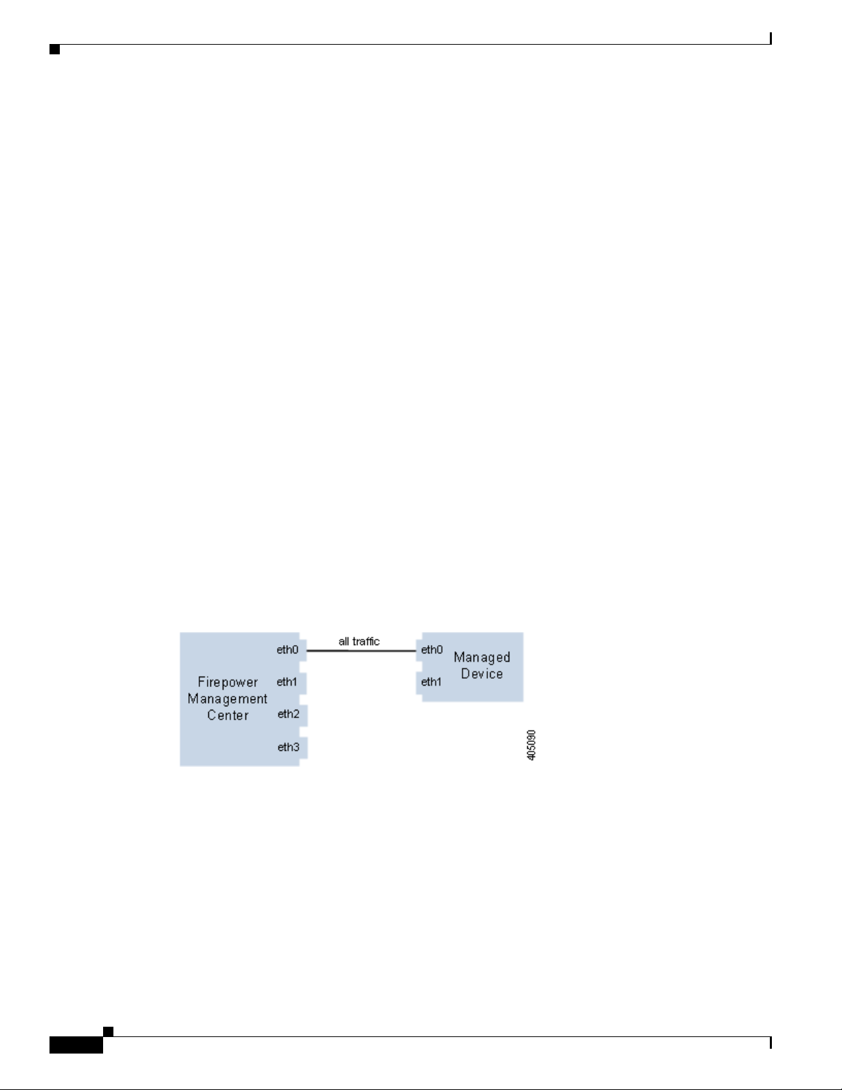
Single Management Interface
When you register your device to a Management Center, you establish a single communication channel
that carries all traffic between the management interface on the Management Center and the management
interface on the device.
The following graphic shows the default single communication channel. One interface carries one
communication channel that contains both management and event traffic.
Multiple Management Interfaces
You can enable and configure multiple management interfaces, each with a specific IPv4 or IPv6 address
and, optionally, a hostname, to provide greater traffic throughput by sending each traffic channel to a
different management interface. Configure a smaller interface to carry the lighter management traffic
load, and a larger interface to carry the heavier event traffic load. You can register devices to separate
management interfaces and configure both traffic channels for the same interface, or use a dedicated
management interface to carry the event traffic channels for all devices managed by the Management
Center.
2-2
Firepower 7000 and 8000 Series Installation Guide
Page 27
Chapter 2 Deploying on a Management Network
You can also create a route from a specific management interface on your Management Center to a
different network, allowing your Management Center to isolate and manage device traffic on one
network separately from device traffic on another network.
Additional management interfaces function the same as the default management interface with the
following exceptions:
• You can configure DHCP on the default (eth0) management interface only. Additional (eth1 and so
on) interfaces require unique static IP addresses and hostnames. Cisco recommends that you do not
set up DNS entries for additional management interfaces but instead register Management Centers
and devices by IP addresses only for these interfaces.
• You must configure both traffic channels to use the same management interface when you use a
non-default management interface to connect your Management Center and managed device and
those appliances are separated by a NAT device.
• You can use Lights-Out Management on the default management interface only.
• On the 70xx Family, you can separate traffic into two channels and configure those channels to send
traffic to one or more management interfaces on the Management Center. However, because the
70xx Family contains only one management interface, the device receives traffic sent from the
Management Center on only one management interface.
Deployment Options
Deployment Options
You can manage traffic flow using traffic channels to improve performance on your system using one or
more management interfaces. In addition, you can create a route to a different network using a specific
management interface on the Management Center and its managed device, allowing you to isolate traffic
between devices on different networks. For more information, see the following sections:
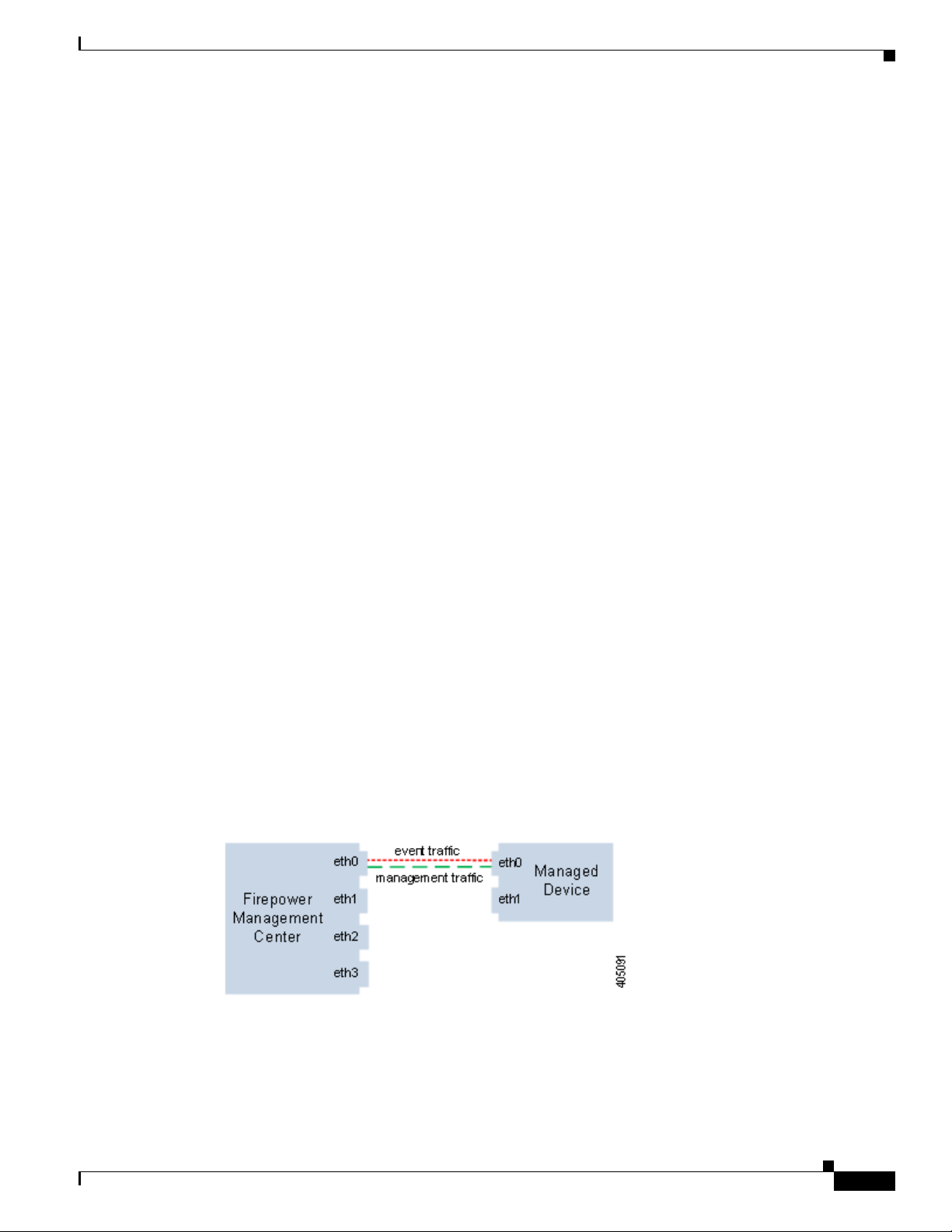
Deploying with Traffic Channels
When you use two traffic channels on one management interface, you create two connections between
the Management Center and the managed device. One channel carries management traffic and one
carries event traffic, separately and on the same interface.
The following example shows the communication channel with two separate traffic channels on the same
interface.
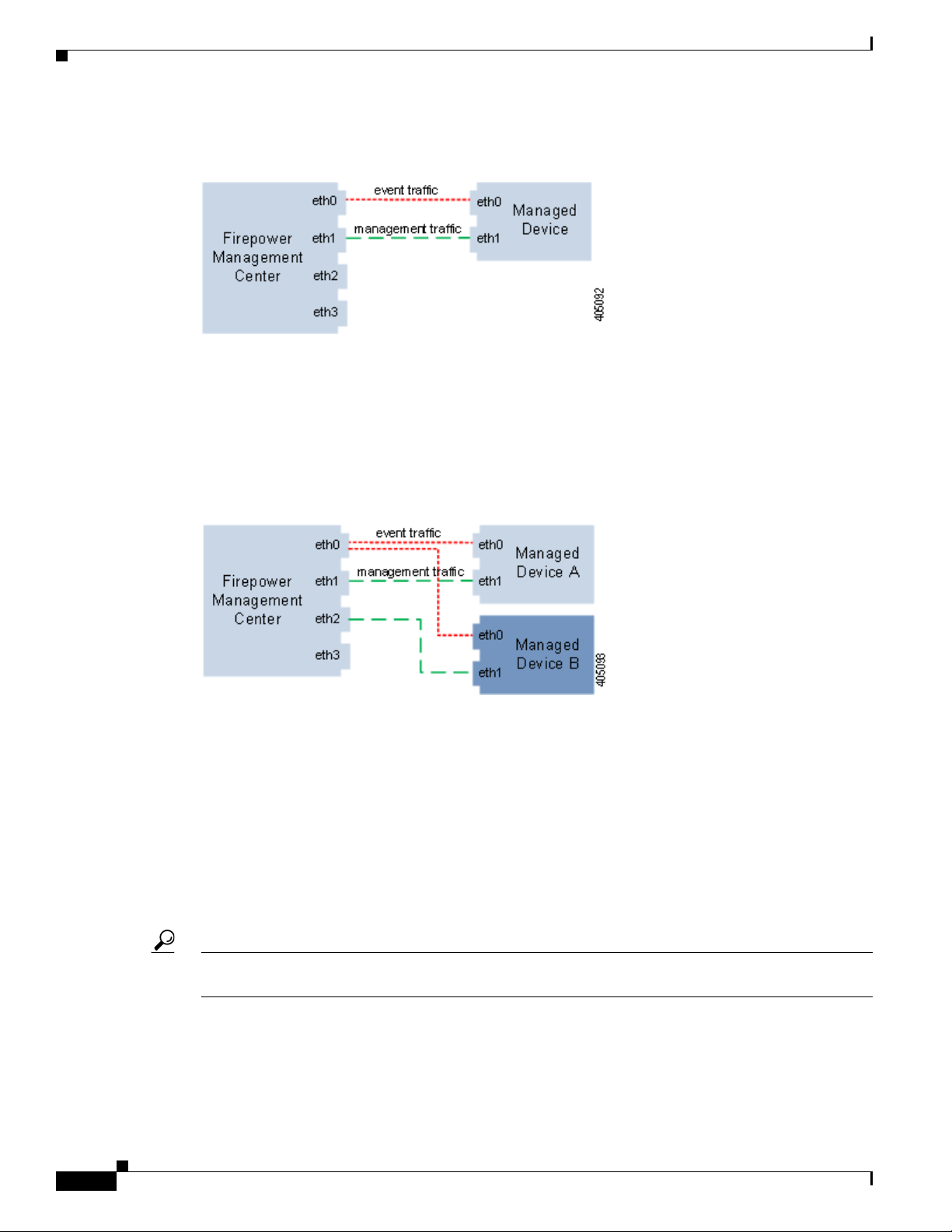
When you use multiple management interfaces, you can improve your performance by dividing the
traffic channels over two management interfaces, thus increasing the traffic flow by adding the capacity
of both interfaces. One interface carries the management traffic channel and the other carries the event
traffic channel. If either interface fails, all traffic reroutes to the active interface and the connection is
maintained.
Firepower 7000 and 8000 Series Installation Guide
2-3
Page 28
Deploying with Network Routes
The following graphic shows the management traffic channel and the event traffic channel over two
management interfaces.
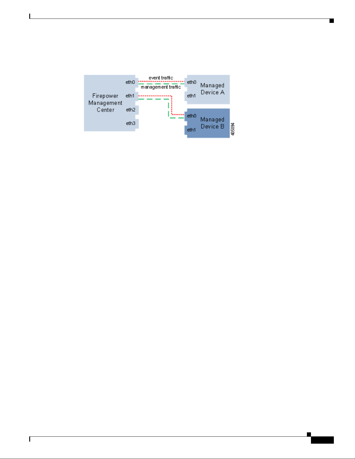
You can use a dedicated management interface to carry only event traffic from multiple devices. In this
configuration, each device is registered to a different management interface to carry the management
traffic channel, and one management interface on the Management Center carries all event traffic
channels from all devices. If an interface fails, traffic reroutes to the active interface and the connection
is maintained. Note that because event traffic for all devices is carried on the same interface, traffic is
not isolated between networks.
The following graphic shows two devices using different management channel traffic interfaces sharing
the same dedicated interface for event traffic channels.
Chapter 2 Deploying on a Management Network
Deploying with Network Routes
You can create a route from a specific management interface on your Management Center to a different
network. When you register a device from that network to the specified management interface on the
Management Center, you provide an isolated connection between the Management Center and the device
on a different network. Configure both traffic channels to use the same management interface to ensure
that traffic from that device remains isolated from device traffic on other networks. Because the routed
interface is isolated from all other interfaces on the Management Center, if the routed management
interface fails, the connection is lost.
Tip You must register a device to the static IP address of any management interface other than the default
(eth0) management interface. DHCP is supported only on the default management interface.
After you install your Management Center, you configure multiple management interfaces using the web
interface. See Configuring Appliance Settings in the Firepower Management Center Configuration
Guide for more information.
Firepower 7000 and 8000 Series Installation Guide
2-4
Page 29
Chapter 2 Deploying on a Management Network
The following graphic shows two devices isolating network traffic by using separate management
interfaces for all traffic. You can add more management interfaces to configure separate management
and event traffic channel interfaces for each device.
Security Considerations
To deploy your management interfaces in a secure environment, Cisco recommends that you consider
the following:
• Always connect the management interface to a trusted internal management network that is
protected from unauthorized access.
Security Considerations
• Identify the specific workstation IP addresses that can be allowed to access appliances. Restrict
access to the appliance to only those specific hosts using Access Lists within the appliance’s system
policy. For more information, see the Firepower Management Center Configuration Guide.
Special Case: Connecting 8000 Series Devices
Supported Devices: 8000 Series
When you register an 8000 Series device to your Management Center, you must either auto-negotiate on
both sides of the connection, or set both sides to the same static speed to ensure a stable network link.
8000 Series devices do not support half duplex network links; they also do not support differences in
speed or duplex configurations at opposite ends of a connection.
Firepower 7000 and 8000 Series Installation Guide
2-5
Page 30

Special Case: Connecting 8000 Series Devices
Chapter 2 Deploying on a Management Network
2-6
Firepower 7000 and 8000 Series Installation Guide
Page 31

Deploying Firepower Managed Devices
After you register a device to a Firepower Management Center, you deploy the sensing interfaces of the
device on a network segment to monitor traffic using an intrusion detection system or protect your
network from threats using an intrusion prevention system.
Note See the ASA documentation for more information on deployment scenarios for ASA FirePOWER
devices.
For additional information about deployments, consult the Best Practices Guide, available from the
Cisco sales department.
Sensing Deployment Considerations
Your sensing deployment decisions will be based on a variety of factors. Answering these questions can
help you understand the vulnerable areas of your network and clarify your intrusion detection and
prevention needs:
• Will you be deploying your managed device with passive or inline interfaces? Does your device
support a mix of interfaces, some passive and others inline? See Understanding Sensing Interfaces,
page 3-2 for more information.
• How will you connect the managed devices to the network? Hubs? Taps? Spanning ports on
switches? Virtual switches? See Connecting Devices to Your Network, page 3-4 for more
information.
CHA PT ER
3
• Do you want to detect every attack on your network, or do you only want to know about attacks that
penetrate your firewall? Do you have specific assets on your network such as financial, accounting,
or personnel records, production code, or other sensitive, protected information that require special
security policies? See Deployment Options, page 3-7 for more information.
• Will you use multiple sensing interfaces on your managed device to recombine the separate
connections from a network tap, or to capture and evaluate traffic from different networks? Do you
want to use the multiple sensing interfaces to perform as a virtual router or a virtual switch? See
Using Multiple Sensing Interfaces on a Managed Device, page 3-16 for more information.
• Do you provide VPN or modem access for remote workers? Do you have remote offices that also
require an intrusion protection deployment? Do you employ contractors or other temporary
employees? Are they restricted to specific network segments? Do you integrate your network with
the networks of other organizations such as customers, suppliers, or business partners? See Complex
Network Deployments, page 3-18 for more information.
Firepower 7000 and 8000 Series Installation Guide
3-1
Page 32

Understanding Sensing Interfaces
Understanding Sensing Interfaces
The sections that follow describe how different sensing interfaces affect the capabilities of the Firepower
System. In addition to passive and inline interfaces, you can also have routed, switched, and hybrid
interfaces.
Sensing interfaces are located on the front of the device. To identify your sensing interfaces, see
Identifying the Sensing Interfaces, page 4-3.
Passive Interfaces
You can configure a passive deployment to monitor traffic flowing across a network using a switch
SPAN, virtual switch, or mirror port, allowing traffic to be copied from other ports on the switch. Passive
interfaces allow you to inspect traffic within the network without being in the flow of network traffic.
When configured in a passive deployment, the system cannot take certain actions such as blocking or
shaping traffic. Passive interfaces receive all traffic unconditionally and do not retransmit received
traffic.
Chapter 3 Deploying Firepower Managed Devices
Inline Interfaces
You configure an inline deployment transparently on a network segment by binding two ports together.
Inline interfaces allow you to install a device in any network configuration without the configuration of
adjacent network devices. Inline interfaces receive all traffic unconditionally, then retransmit all traffic
received on these interfaces except traffic explicitly dropped. You must assign a pair of inline interfaces
to an inline set before they can handle traffic in an inline deployment.
Note If you configure an interface as an inline interface, the adjacent port on its NetMod automatically
becomes an inline interface as well to complete the pair.
Configurable bypass inline sets allow you to select how your traffic is handled if your hardware fails
completely (for example, the device loses power). You may determine that connectivity is critical on one
network segment, and, on another network segment, you cannot permit uninspected traffic. Using
configurable bypass inline sets, you can manage the traffic flow of your network traffic in one of the
following ways:
• Bypass: an interface pair configured for bypass allows all traffic to flow if the device fails. The
• Non-bypass: an interface pair configured for non-bypass stops all traffic if the device fails. Traffic
Configure the inline set as bypass to ensure that traffic continues to flow if your device fails. Configure
the inline set as non-bypass to stop traffic if the device fails. Note that reimaging resets Firepower
devices in bypass mode to a non-bypass configuration and disrupts traffic on your network until you
reconfigure bypass mode. For more information, see Traffic Flow During the Restore Process, page 8-1.
traffic bypasses the device and any inspection or other processing by the device. Bypass allows
uninspected traffic across the network segment, but ensures that the network connectivity is
maintained.
that reaches the failed device does not enter the device. Non-bypass does not permit traffic to pass
uninspected, but the network segment loses connectivity if the device fails. Use non-bypass
interfaces in deployment situations where network security is more important than loss of traffic.
3-2
Firepower 7000 and 8000 Series Installation Guide
Page 33

Chapter 3 Deploying Firepower Managed Devices
All Firepower devices can contain configurable bypass interfaces. 8000 Series devices can also contain
NetMods with interfaces that cannot be configured for bypass. For more information on NetMods, see
Firepower 8000 Series Modules, page 7-32. Other advanced interface options include tap mode,
propagate link state, transparent inline mode, and strict TCP mode. For information on how to configure
your inline interface sets, see Configuring Inline Sets in the Firepower Management Center
Configuration Guide. For more information on using inline interfaces, see Connecting Devices to Your
Network, page 3-4.
You cannot configure bypass interfaces on an ASA FirePOWER device using the Firepower
Management Center. For information on configuring an ASA FirePOWER device in inline mode, see the
ASA documentation.
Switched Interfaces
You can configure switched interfaces on a Firepower device in a Layer 2 deployment to provide packet
switching between two or more networks. You can also configure virtual switches on Firepower devices
to operate as standalone broadcast domains, dividing your network into logical segments. A virtual
switch uses the media access control (MAC) address from a host to determine where to send packets.
Switched interfaces can have either a physical or logical configuration:
• Physical switched interfaces are physical interfaces with switching configured. Use physical
switched interfaces to handle untagged VLAN traffic.
• Logical switched interfaces are an association between a physical interface and a VLAN tag. Use
logical interfaces to handle traffic with designated VLAN tags.
Understanding Sensing Interfaces
Virtual switches can operate as standalone broadcast domains, dividing your network into logical
segments. A virtual switch uses the media access control (MAC) address from a host to determine where
to send packets. When you configure a virtual switch, the switch initially broadcasts packets through
every available port on the switch. Over time, the switch uses tagged return traffic to learn which hosts
reside on the networks connected to each port.
You can configure your device as a virtual switch and use the remaining interfaces to connect to network
segments you want to monitor. To use a virtual switch on your device, create physical switched interfaces
and then follow the instructions for Setting Up Virtual Switches in the Firepower Management Center
Configuration Guide.
Routed Interfaces
You can configure routed interfaces on a Firepower device in a Layer 3 deployment so that it routes
traffic between two or more interfaces. You must assign an IP address to each interface and assign the
interfaces to a virtual router to route traffic.
You can configure routed interfaces for use with a gateway virtual private network (gateway VPN) or
with network address translation (NAT). For more information, see Deploying a Gateway VPN,
page 3-10 and Deploying with Policy-Based NAT, page 3-11.
You can also configure the system to route packets by making packet forwarding decisions according to
the destination address. Interfaces configured as routed interfaces receive and forward the Layer 3
traffic. Routers obtain the destination from the outgoing interface based on the forwarding criteria, and
access control rules designate the security policies to be applied.
Routed interfaces can have either a physical or logical configuration:
Firepower 7000 and 8000 Series Installation Guide
3-3
Page 34

Connecting Devices to Your Network
• Physical routed interfaces are physical interfaces with routing configured. Uses physical routed
• Logical switched interfaces are an association between a physical interface and a VLAN tag. Use
To use routed interfaces in a Layer 3 deployment, you must configure virtual routers and assign routed
interfaces to them. A virtual router is a group of routed interfaces that route Layer 3 traffic.
You can configure your device as a virtual router and use the remaining interfaces to connect to network
segments you want to monitor. You can also enable strict TCP enforcement for maximum TCP security.
To use a virtual router on your device, create physical routed interfaces on your device and then follow
the instructions for Setting Up Virtual Routers in the Firepower Management Center Configuration
Guide.
Hybrid Interfaces
You can configure logical hybrid interfaces on Firepower devices that allow the Firepower System to
bridge traffic between virtual routers and virtual switches. If IP traffic received on interfaces in a virtual
switch is addressed to the MAC address of an associated hybrid logical interface, the system handles it
as Layer 3 traffic and either routes or responds to the traffic depending on the destination IP address. If
the system receives any other traffic, it handles it as Layer 2 traffic and switches it appropriately.
To create a hybrid interface, you first configure a virtual switch and virtual router, then add the virtual
switch and virtual router to the hybrid interface. A hybrid interface that is not associated with both a
virtual switch and a virtual router is not available for routing, and does not generate or respond to traffic.
Chapter 3 Deploying Firepower Managed Devices
interfaces to handle untagged VLAN traffic.
logical interfaces to handle traffic with designated VLAN tags.
You can configure hybrid interfaces with network address translation (NAT) to pass traffic between
networks. For more information, see Deploying with Policy-Based NAT, page 3-11.
If you want to use hybrid interfaces on your device, define a hybrid interface on the device and then
follow the instructions for Setting Up Hybrid Interfaces in the Firepower Management Center
Configuration Guide.
Connecting Devices to Your Network
You can connect the sensing interfaces on your managed devices to your network in several ways.
Configure a hub or network tap using either passive or inline interfaces, or a span port using passive
interfaces.
Using a Hub
An Ethernet hub is a simple way to ensure that the managed device can see all the traffic on a network
segment. Most hubs of this type take the IP traffic meant for any of the hosts on the segment and
broadcast it to all the devices connected to the hub. Connect the interface set to the hub to monitor all
incoming and outgoing traffic on the segment. Using a hub does not guarantee that the detection engine
sees every packet on a higher volume network because of the potential of packet collision. For a simple
network with low traffic, this is not likely to be a problem. In a high-traffic network, a different option
may provide better results. Note that if the hub fails or loses power, the network connection is broken.
In a simple network, the network would be down.
3-4
Firepower 7000 and 8000 Series Installation Guide
Page 35

Chapter 3 Deploying Firepower Managed Devices
Some devices are marketed as hubs but actually function as switches and do not broadcast each packet
to every port. If you attach your managed device to a hub, but do not see all the traffic, you may need to
purchase a different hub or use a switch with a Span port.
Using a Span Port
Many network switches include a span port that mirrors traffic from one or more ports. By connecting
an interface set to the span port, you can monitor the combined traffic from all ports, generally both
incoming and outgoing. If you already have a switch that includes this feature on your network, in the
proper location, then you can deploy the detection on multiple segments with little extra equipment cost
beyond the cost of the managed device. In high-traffic networks, this solution has its limitations. If the
span port can handle 200Mbps and each of three mirrored ports can handle up to 100Mbps, then the span
port is likely to become oversubscribed and drop packets, lowering the effectiveness of the managed
device.
Using a Network Tap
Connecting Devices to Your Network
Network taps allow you to passively monitor traffic without interrupting the network flow or changing
the network topology. Taps are readily available for different bandwidths and allow you to analyze both
incoming and outgoing packets on a network segment. Because you can monitor only a single network
segment with most taps, they are not a good solution if you want to monitor the traffic on two of the eight
ports on a switch. Instead, you would install the tap between the router and the switch and access the full
IP stream to the switch.
By design, network taps divide incoming and outgoing traffic into two different streams over two
different cables. Managed devices offer multiple sensing interface options that recombine the two sides
of the conversation so that the entire traffic stream is evaluated by the decoders, the preprocessors, and
the detection engine.
Cabling Inline Deployments on Copper Interfaces
If you deploy your device inline on your network and you want to use your device’s bypass capabilities
to maintain network connectivity if the device fails, you must pay special attention to how you cable the
connections.
If you deploy a device with fiber bypass capable interfaces, there are no special cabling issues beyond
ensuring that the connections are securely fastened and the cables are not kinked. However, if you are
deploying devices with copper rather than fiber network interfaces, then you must be aware of the device
model that you are using, because different device models use different network cards. Note that some
8000 Series NetMods do not allow bypass configuration.
The network interface cards (NICs) in the device support a feature called Auto-Medium Dependent
Interface Crossover (Auto-MDI-X), which allows network interfaces to configure automatically whether
you use a straight-through or crossover Ethernet cable to connect to another network device. Firepower
devices bypass as crossover connections.
Wire the device as would normally be done without a device deployed. The link should work with power
to the device removed. In most cases you should use two straight-through cables to connect the device
to the two endpoints.
Firepower 7000 and 8000 Series Installation Guide
3-5
Page 36

Connecting Devices to Your Network
Figure 3-1 Crossover Bypass Connection Cabling
The following table indicates where you should use crossover or straight-through cables in your
hardware bypass configurations. Note that a Layer 2 port functions as a straight-through (MDI) endpoint
in the deployment, and a Layer 3 port functions as a crossover (MDIX) endpoint in the deployment. The
total crossovers (cables and appliances) should be an odd number for bypass to function properly.
Table 3-1 Valid Configurations for Hardware Bypass
Endpoint 1 Cable Managed Device Cable Endpoint 2
MDIX straight-through straight-through straight-through MDI
MDI crossover straight-through straight-through MDI
MDI straight-through straight-through crossover MDI
MDI straight-through straight-through straight-through MDIX
MDIX straight-through crossover straight-through MDIX
MDI straight-through crossover straight-through MDI
MDI crossover crossover crossover MDI
MDIX crossover crossover straight-through MDI
Chapter 3 Deploying Firepower Managed Devices
Note that every network environment is likely to be unique, with endpoints that have different
combinations of support for Auto-MDI-X. The easiest way to confirm that you are installing your device
with the correct cabling is to begin by connecting the device to its two endpoints using one crossover
cable and one straight-through cable, but with the device powered down. Ensure that the two endpoints
can communicate. If they cannot communicate, then one of the cables is the incorrect type. Switch one
(and only one) of the cables to the other type, either straight-through or crossover.
After the two endpoints can successfully communicate with the inline device powered down, power up
the device. The Auto-MDI-X feature ensures that the two endpoints will continue to communicate. Note
that if you have to replace an inline device, you should repeat the process of ensuring that the endpoints
can communicate with the new device powered down to protect against the case where the original
device and its replacement have different bypass characteristics.
The Auto-MDI-X setting functions correctly only if you allow the network interfaces to auto-negotiate.
If your network environment requires that you turn off the Auto Negotiate option on the Network
Interface page, then you must specify the correct MDI/MDIX option for your inline network interfaces.
See Configuring Inline Interfaces in the Firepower Management Center Configuration Guide for more
information.
Special Case: Connecting Firepower 8000 Series Devices
When you register a Firepower 8000 Series managed device to your Firepower Management Center, you
must either use auto-negotiation on both sides of the connection, or set both sides to the same static speed
to ensure a stable network link. 8000 Series managed devices do not support half duplex network links;
they also do not support differences in speed or duplex configurations at opposite ends of a connection.
3-6
Firepower 7000 and 8000 Series Installation Guide
Page 37

Chapter 3 Deploying Firepower Managed Devices
Deployment Options
When you place your managed device on a network segment, you can monitor traffic using an intrusion
detection system or protect your network from threats using an intrusion prevention system.
You can also deploy your managed device to function as a virtual switch, virtual router, or gateway VPN.
Additionally, you can use policies to route traffic or control access to traffic on your network.
Deploying with a Virtual Switch
You can create a virtual switch on your managed device by configuring inline interfaces as switched
interfaces. The virtual switch provides Layer 2 packet switching for your deployment. Advanced options
include setting a static MAC address, enabling spanning tree protocol, enabling strict TCP enforcement,
and dropping bridge protocol data units (BPDUs) at the domain level. For information on switched
interfaces, see Switched Interfaces, page 3-3.
A virtual switch must contain two or more switched interfaces to handle traffic. For each virtual switch,
the system switches traffic only to the set of ports configured as switched interfaces. For example, if you
configure a virtual switch with four switched interfaces, when the system receives traffic packets through
one port it only broadcasts these packets to the remaining three ports on the switch.
Deployment Options
To configure a virtual switch to allow traffic, you configure two or more switched interfaces on a
physical port, add and configure a virtual switch, and then assign the virtual switch to the switched
interfaces. The system drops any traffic received on an external physical interface that does not have a
switched interface waiting for it. If the system receives a packet with no VLAN tag and you have not
configured a physical switched interface for that port, it drops the packet. If the system receives a
VLAN-tagged packet and you have not configured a logical switched interface, it also drops the packet.
You can define additional logical switched interfaces on the physical port as needed, but you must assign
a logical switched interface to a virtual switch to handle traffic.
Virtual switches have the advantage of scalability. When you use a physical switch, you are limited by
the number of available ports on the switch. When you replace your physical switch with a virtual switch,
you are limited only by your bandwidth and the level of complexity you want to introduce to your
deployment.
Use a virtual switch where you would use a Layer 2 switch, such as workgroup connectivity and network
segmentation. Layer 2 switches are particularly effective where workers spend most of their time on their
local segment. Larger deployments (for example, deployments that contain broadcast traffic,
Voice-over-IP, or multiple networks) can use virtual switches on smaller network segments of the
deployment.
When you deploy multiple virtual switches on the same managed device, you can maintain separate
levels of security as dictated by the needs of each network.
Firepower 7000 and 8000 Series Installation Guide
3-7
Page 38

Deployment Options
Chapter 3 Deploying Firepower Managed Devices
Figure 3-2 Virtual Switches on a Managed Device
In this example, the managed device monitors traffic from two separate networks, 172.16.1.0/20 and
192.168.1.0/24. Although both networks are monitored by the same managed device, the virtual switch
passes traffic only to those computers or servers on the same network. Traffic can pass from computer
A to computer B through the 172.16.1.0/24 virtual switch (indicated by the blue line) and from computer
B to computer A through the same virtual switch (indicated by the green line). Similarly, traffic can pass
to and from the file and web servers through the 192.168.1.0/24 virtual switch (indicated by the red and
orange lines). However, traffic cannot pass between the computers and the web or file servers because
the computers are not on the same virtual switch as the servers.
For more information on configuring switched interfaces and virtual switches, see Setting Up Virtual
Switches in the Firepower Management Center Configuration Guide.
Deploying with a Virtual Router
You can create a virtual router on a managed device to route traffic between two or more networks, or
to connect a private network to a public network (for example, the Internet). The virtual router connects
two routed interfaces to provide Layer 3 packet forwarding decisions for your deployment according to
the destination address. Optionally, you can enable strict TCP enforcement on the virtual router. For
more information on routed interfaces, see Routed Interfaces, page 3-3. You must use a virtual router
with a gateway VPN. For more information, see Deploying a Gateway VPN, page 3-10.
A virtual router can contain either physical or logical routed configurations from one or more individual
devices within the same broadcast domain. You must associate each logical interface with a VLAN tag
to handle traffic received by the physical interface with that specific tag. You must assign a logical routed
interface to a virtual router to route traffic.
To configure a virtual router, you set up routed interfaces with either physical or logical configurations.
You can configure physical routed interfaces for handling untagged VLAN traffic. You can also create
logical routed interfaces for handling traffic with designated VLAN tags. The system drops any traffic
received on an external physical interface that does not have a routed interface waiting for it. If the
system receives a packet with no VLAN tag and you have not configured a physical routed interface for
that port, it drops the packet. If the system receives a VLAN-tagged packet and you have not configured
a logical routed interface, it also drops the packet.
Virtual routers have the advantage of scalability. Where physical routers limit the number of networks
you can connect, multiple virtual routers can be configured on the same managed device. Putting
multiple routers on the same device reduces the physical complexity of your deployment, allowing you
to monitor and manage multiple routers from one device.
Use a virtual router where you would use a Layer 3 physical router to forward traffic between multiple
networks in your deployment, or to connect your private network to a public network. Virtual routers are
particularly effective in large deployments where you have many networks or network segments with
different security requirements.
3-8
Firepower 7000 and 8000 Series Installation Guide
Page 39

Chapter 3 Deploying Firepower Managed Devices
When you deploy a virtual router on your managed device, you can use one appliance to connect multiple
networks to each other, and to the Internet.
Figure 3-3 Virtual Routers on a Managed Device
In this example, the managed device contains a virtual router to allow traffic to travel between the
computers on network 172.16.1.0/20 and the servers on network 192.168.1.0/24 (indicated by the blue
and green lines). A third interface on the virtual router allows traffic from each network to pass to the
firewall and back (indicated by the red and orange lines).
For more information, see Setting Up Virtual Routers in the Firepower Management Center
Configuration Guide.
Deployment Options
Deploying with Hybrid Interfaces
You can create a hybrid interface on a managed device to route traffic between Layer 2 and Layer 3
networks using a virtual switch and a virtual router. This provides one interface that can both route local
traffic on the switch and route traffic to and from an external network. For best results, configure
policy-based NAT on the interface to provide network address translation on the hybrid interface. See
Deploying with Policy-Based NAT, page 3-11.
A hybrid interface must contain one or more switched interfaces and one or more routed interfaces. A
common deployment consists of two switched interfaces configured as a virtual switch to pass traffic on
a local network and virtual routers to route traffic to networks, either private or public.
To create a hybrid interface, you first configure a virtual switch and virtual router, then add the virtual
switch and virtual router to the hybrid interface. A hybrid interface that is not associated with both a
virtual switch and a virtual router is not available for routing, and does not generate or respond to traffic.
Hybrid interfaces have the advantage of compactness and scalability. Using a single hybrid interface
combines both Layer 2 and Layer 3 traffic routing functions in a single interface, reducing the number
of physical appliances in the deployment and providing a single management interface for the traffic.
Use a hybrid interface where you need both Layer 2 and Layer 3 routing functions. This deployment can
be ideal for small segments of your deployment where you have limited space and resources.
When you deploy a hybrid interface, you can allow traffic to pass from your local network to an external
or public network, such as the Internet, while addressing separate security considerations for the virtual
switch and virtual router in the hybrid interface.
Firepower 7000 and 8000 Series Installation Guide
3-9
Page 40

Deployment Options
Chapter 3 Deploying Firepower Managed Devices
Figure 3-4 Hybrid Interface on a Managed Device
In this example, computer A and computer B are on the same network and communicate using a Layer
2 virtual switch configured on the managed device (indicated by the blue and green lines). A virtual
router configured on the managed device provides Layer 3 access to the firewall. A hybrid interface
combines the Layer 2 and Layer 3 capabilities of the virtual switch and virtual router to allow traffic to
pass from each computer through the hybrid interface to the firewall (indicated by the red and orange
lines).
For more information, see Setting Up Hybrid Interfaces in the Firepower Management Center
Configuration Guide.
Deploying a Gateway VPN
License: VPN
You can create a gateway virtual private network (gateway VPN) connection to establish a secure tunnel
between a local gateway and a remote gateway. The secure tunnel between the gateways protects
communication between them.
You configure the Firepower System to build secure VPN tunnels from the virtual routers of Cisco
managed devices to remote devices or other third-party VPN endpoints using the Internet Protocol
Security (IPSec) protocol suite. After the VPN connection is established, the hosts behind the local
gateway can connect to the hosts behind the remote gateway through the secure VPN tunnel. The VPN
endpoints authenticate each other with either the Internet Key Exchange (IKE) version 1 or version 2
protocol to create a security association for the tunnel. The system runs in either IPSec authentication
header (AH) mode or the IPSec encapsulating security payload (ESP) mode. Both AH and ESP provide
authentication, and ESP also provides encryption.
A gateway VPN can be used in a point-to-point, star, or mesh deployment:
• Point-to-point deployments connect two endpoints with each other in a direct one-to-one
relationship. Both endpoints are configured as peer devices, and either device can initiate the
secured connection. At least one device must be a VPN-enabled managed device.
Use a point-to-point deployment to maintain your network security when a host at a remote location
uses public networks to connect to a host in your network.
• Star deployments establish a secure connection between a hub and multiple remote endpoints (leaf
nodes). Each connection between the hub node and an individual leaf node is a separate VPN tunnel.
Typically, the hub node is the VPN-enabled managed device, located at the main office. Leaf nodes
are located at branch offices and initiate most of the traffic.
Use a star deployment to connect an organization’s main and branch office locations using secure
connections over the Internet or other third-party network to provide all employees with controlled
access to the organization’s network.
3-10
Firepower 7000 and 8000 Series Installation Guide
Page 41

Chapter 3 Deploying Firepower Managed Devices
• Mesh deployments connect all endpoints together by means of VPN tunnels. This offers redundancy
in that when one endpoint fails, the remaining endpoints can still communicate with each other.
Use a mesh deployment to connect a group of decentralized branch office locations to ensure that
traffic can travel even if one or more VPN tunnels fails. The number of VPN-enabled managed
devices you deploy in this configuration controls the level of redundancy.
For more information on gateway VPN configuration and deployments, see Gateway VPN in the
Firepower Management Center Configuration Guide.
Deploying with Policy-Based NAT
You can use policy-based network address translation (NAT) to define policies that specify how you
want to perform NAT. You can target your policies to a single interface, one or more devices, or entire
networks.
You can configure static (one-to-one) or dynamic (one-to-many) translation. Note that dynamic
translations are order-dependent where rules are searched in order until the first matching rule applies.
Policy-based NAT typically operates in the following deployments:
Deployment Options
• Hide your private network address.
When you access a public network from your private network, NAT translates your private network
address to your public network address. Your specific private network address is hidden from the
public network.
• Allow access to a private network service.
When a public network accesses your private network, NAT translates your public address to your
private network address. The public network can access your specific private network address.
• Redirect traffic between multiple private networks.
When a server on a private network accesses a server on a connected private network, NAT translates
the private addresses between the two private networks to ensure there is no duplication in private
addresses and traffic can travel between them.
Using policy-based NAT removes the need for additional hardware and consolidates the configuration
of your intrusion detection or prevention system and NAT into a single user interface. For more
information, see Using NAT Policies in the Firepower Management Center Configuration Guide.
Deploying with Access Control
Access control is a policy-based feature that allows you to specify, inspect, and log the traffic that can
enter, exit, or travel within your network. The following section describes how access control can
function in your deployment. See the Firepower Management Center Configuration Guide for more
information on this feature.
An access control policy determines how the system handles traffic on your network. You can add access
control rules to your policy to provide more granular control over how you handle and log network
traffic.
An access control policy that does not include access control rules uses one of the following default
actions to handle traffic:
• block all traffic from entering your network
• trust all traffic to enter your network without further inspection
Firepower 7000 and 8000 Series Installation Guide
3-11
Page 42

Deployment Options
Chapter 3 Deploying Firepower Managed Devices
• allow all traffic to enter your network, and inspect the traffic with a network discovery policy only
• allow all traffic to enter your network, and inspect the traffic with intrusion and network discovery
policies
Access control rules further define how traffic is handled by targeted devices, from simple IP address
matching to complex scenarios involving different users, applications, ports, and URLs. For each rule,
you specify a rule action, that is, whether to trust, monitor, block, or inspect matching traffic with an
intrusion or file policy.
Access control can filter traffic based on Security Intelligence data, a feature that allows you to specify
the traffic that can traverse your network, per access control policy, based on the source or destination
IP address. This feature can create a blacklist of disallowed IP addresses whose traffic is blocked and
not inspected.
The sample deployment illustrates common network segments. Deploying your managed devices in each
of these locations serves different purposes. The following sections describe typical location
recommendations:
• Inside the Firewall, page 3-12 explains how access control functions on traffic that passes through
the firewall.
• On the DMZ, page 3-13 explains how access control within the DMZ can protect outward-facing
servers.
• On the Internal Network, page 3-14 explains how access control can protect your internal network
from intentional or accidental attack.
Inside the Firewall
• On the Core Network, page 3-14 explains how an access control policy with strict rules can protect
your critical assets.
• On a Remote or Mobile Network, page 3-15 explains how access control can monitor and protect
the network from traffic at remote locations or on mobile devices.
Managed devices inside the firewall monitor inbound traffic allowed by the firewall or traffic that passes
the firewall due to misconfiguration. Common network segments include the DMZ, the internal network,
the core, mobile access, and remote networks.
The diagram below illustrates traffic flow through the Firepower System, and provide some details on
the types of inspection performed on that traffic. Note that the system does not inspect fast-pathed or
blacklisted traffic. For traffic handled by an access control rule or default action, flow and inspection
depend on the rule action. Although rule actions are not shown in the diagram for simplicity, the system
does not perform any kind of inspection on trusted or blocked traffic. Additionally, file inspection is not
supported with the default action.
3-12
Firepower 7000 and 8000 Series Installation Guide
Page 43

Chapter 3 Deploying Firepower Managed Devices
An incoming packet is first checked against any fast-path rules. If there is a match, the traffic is
fast-pathed. If there is no match, Security Intelligence-based filtering determines if the packet is
blacklisted. If not, any access control rules are applied. If the packet meets the conditions of a rule, traffic
flow and inspection depend on the rule action. If no rules match the packet, traffic flow and inspection
depend on the default policy action. (An exception occurs with Monitor rules, which allow traffic to
continue to be evaluated.) The default action on each access control policy manages traffic that has not
been fast-pathed or blacklisted, or matched by any non-Monitor rule. Note that fast-path is available only
for 8000 Series devices.
You can create access control rules to provide more granular control over how you handle and log
network traffic. For each rule, you specify an action (trust, monitor, block, or inspect) to apply to traffic
that meets specific criteria.
On the DMZ
The DMZ contains outward-facing servers (for example, web, FTP, DNS, and mail), and may also
provide services such as mail relay and web proxy to users on the internal network.
Content stored in the DMZ is static, and changes are planned and executed with clear communication
and advance notice. Attacks in this segment are typically inbound and become immediately apparent
because only planned changes should occur on the servers in the DMZ. An effective access control
policy for this segment tightly controls access to services and searches for any new network events.
Servers in the DMZ can contain a database that the DMZ can query via the network. Like the DMZ, there
should be no unexpected changes, but the database content is more sensitive and requires greater
protection than a web site or other DMZ service. A strong intrusion policy, in addition to the DMZ access
control policy, is an effective strategy.
Deployment Options
A managed device deployed on this segment can detect attacks directed to the Internet that originate
from a compromised server in the DMZ. Monitoring network traffic using Network Discovery can help
you monitor these exposed servers for changes (for example, an unexpected service suddenly appearing)
that could indicate a compromised server in the DMZ.
Firepower 7000 and 8000 Series Installation Guide
3-13
Page 44

Deployment Options
On the Internal Network
A malicious attack can originate from a computer on your internal network. This can be a deliberate act
(for example, an unknown computer appears unexpectedly on your network), or an accidental infection
(for example, a work laptop infected off-site is connected to the network and spreads a virus). Risk on
the internal network can also be outbound (for example, a computer sends information to a suspicious
external IP address).
This dynamic network requires a strict access control policy for all internal traffic in addition to
outbound traffic. Add access control rules to tightly control traffic between users and applications.
Chapter 3 Deploying Firepower Managed Devices
On the Core Network
Core assets are those assets critical to the success of your business that must be protected at all cost.
Although core assets vary depending on the nature of your business, typical core assets include financial
and management centers or intellectual property repositories. If the security on the core assets is
breached, your business can be destroyed.
Although this segment must be readily available for your business to function, it must be tightly
restricted controlled. Access control should ensure that these assets cannot be reached by those network
segments with the highest risk, such as remote networks or mobile devices. Always use the most
aggressive control on this segment, with strict rules for user and application access.
3-14
Firepower 7000 and 8000 Series Installation Guide
Page 45

Chapter 3 Deploying Firepower Managed Devices
On a Remote or Mobile Network
Remote networks, located off-site, often use a virtual private network (VPN) to provide access to the
primary network. Mobile devices and the use of personal devices for business purposes (for example,
using a “smart phone” to access corporate email) are becoming increasingly common.
Deployment Options
These networks can be highly dynamic environments with rapid and continual change. Deploying a
managed device on a dedicated mobile or remote network allows you to create a strict access control
policy to monitor and manage traffic to and from unknown external sources. Your policy can reduce your
risk by rigidly limiting how users, network, and applications access core resources.
Firepower 7000 and 8000 Series Installation Guide
3-15
Page 46

Chapter 3 Deploying Firepower Managed Devices
Using Multiple Sensing Interfaces on a Managed Device
Using Multiple Sensing Interfaces on a Managed Device
The managed device offers multiple sensing interfaces on its network modules. You can use multiple
sensing interfaces on managed devices to:
• recombine the separate connections from a network tap
• capture and evaluate traffic from different networks
• perform as a virtual router
• perform as a virtual switch
Note Although each sensing interface is capable of receiving the full throughput for which the device is rated,
the total traffic on the managed device cannot exceed its bandwidth rating without some packet loss.
Deploying multiple sensing interfaces on a managed device with a network tap is a straightforward
process. The following diagram shows a network tap installed on a high-traffic network segment.
3-16
In this scenario, the tap transmits incoming and outgoing traffic through separate sensing interfaces.
When you connect the multiple sensing interface adapter card on the managed device to the tap, the
managed device is able to combine the traffic into a single data stream so that it can be analyzed.
Note that with a gigabit optical tap, as shown in the illustration below, both sets of sensing interfaces on
the managed device are used by the connectors from the tap.
Firepower 7000 and 8000 Series Installation Guide
Page 47

Chapter 3 Deploying Firepower Managed Devices
Using Multiple Sensing Interfaces on a Managed Device
You can use the virtual switch to replace both the tap and the switch in your deployment. Note that if
you replace the tap with a virtual switch, you lose the tap packet delivery guarantee.
You can also create interfaces to capture data from separate networks. The following diagram shows a
single device with a dual sensing interface adapter and two interfaces connected to two networks.
In addition to using one device to monitor both network segments, you can use the virtual switch
capability of the device to replace both switches in your deployment.
Firepower 7000 and 8000 Series Installation Guide
3-17
Page 48

Complex Network Deployments
Complex Network Deployments
Your enterprise’s network may require remote access, such as using a VPN, or have multiple entry
points, such as a business partner or banking connection.
Integrating with VPNs
Chapter 3 Deploying Firepower Managed Devices
Virtual private networks, or VPNs, use IP tunneling techniques to provide the security of a local network
to remote users over the Internet. In general, VPN solutions encrypt the data payload in an IP packet.
The IP header is unencrypted so that the packet can be transmitted over public networks in much the
same way as any other packet. When the packet arrives at its destination network, the payload is
decrypted and the packet is directed to the proper host.
Because network appliances cannot analyze the encrypted payload of a VPN packet, placing managed
devices outside the terminating endpoints of the VPN connections ensures that all packet information
can be accessed. The following diagram illustrates how managed devices can be deployed in a VPN
environment.
You can replace the firewall and the tap on either side of the VPN connection with the managed device.
Note that if you replace the tap with a managed device, you lose the tap packet delivery guarantee.
3-18
Firepower 7000 and 8000 Series Installation Guide
Page 49

Chapter 3 Deploying Firepower Managed Devices
Detecting Intrusions on Other Points of Entry
Many networks include more than one access point. Instead of a single border router that connects to the
Internet, some enterprises use a combination of the Internet, modem banks, and direct links to business
partner networks. In general, you should deploy managed devices near firewalls (either inside the
firewall, outside the firewall, or both) and on network segments that are important to the integrity and
confidentiality of your business data. The following diagram shows how managed devices can be
installed at key locations on a complex network with multiple entry points.
Complex Network Deployments
You can replace the firewall and the router with the managed device deployed on that network segment.
Firepower 7000 and 8000 Series Installation Guide
3-19
Page 50

Complex Network Deployments
Chapter 3 Deploying Firepower Managed Devices
Deploying in Multi-Site Environments
Many organizations want to extend intrusion detection across a geographically disparate enterprise and
then analyze all the data from one location. The Firepower System supports this by offering the
Firepower Management Center, which aggregates and correlates events from managed devices deployed
throughout the organization’s many locations. Unlike deploying multiple managed devices and
Firepower Management Centers in the same geographic location on the same network, when deploying
managed devices in disparate geographic locations, you must take precautions to ensure the security of
the managed devices and the data stream. To secure the data, you must isolate the managed devices and
Firepower Management Center from unprotected networks. You can do this by transmitting the data
stream from the managed devices over a VPN or with some other secure tunneling protocol as shown in
the following diagram.
3-20
Firepower 7000 and 8000 Series Installation Guide
Page 51

Chapter 3 Deploying Firepower Managed Devices
Complex Network Deployments
You can replace the firewalls and routers with the managed device deployed in each network segment.
Firepower 7000 and 8000 Series Installation Guide
3-21
Page 52

Complex Network Deployments
Chapter 3 Deploying Firepower Managed Devices
Integrating Multiple Management Interfaces within a Complex Network
You can configure multiple management interfaces in any deployment to isolate traffic from devices that
monitor different networks and are managed by the same Firepower Management Center. Multiple
management interfaces allow you to add a management interface with a unique IP address (IPv4 or IPv6)
to your Firepower Management Center, and create a route from that management interface to a network
that contains the device you want to manage. When you register your device to the new management
interface, traffic on that device is isolated from traffic on devices registered to the default management
interface on the Firepower Management Center.
Tip You must register a device to the static IP address of any management interface other than the default
(eth0) management interface. DHCP is supported only on the default management interface.
Firepower 7000 and 8000 Series Installation Guide
3-22
Page 53

Chapter 3 Deploying Firepower Managed Devices
Multiple management interfaces are supported in a NAT environment provided you do not use separate
management interfaces for traffic channels. See Deploying on a Management Network, page 2-1 for
more information. Note that Lights-Out Management is supported only on the default management
interface, not additional management interfaces.
After you install your Firepower Management Center, you configure multiple management interfaces
using the web interface. See Configuring Appliance Settings in theFirepower Management Center
Configuration Guide for more information.
Integrating Managed Devices within Complex Networks
You can deploy managed devices in more complex network topologies than a simple multi-sector
network. This section describes the issues surrounding network discovery and vulnerability analysis
when deploying in environments where proxy servers, NAT devices, and VPNs exist, in addition to
information about using the Firepower Management Center to manage multiple managed devices and the
deployment and management of managed devices in a multi-site environment.
Integrating with Proxy Servers and NAT
Complex Network Deployments
Network address translation (NAT) devices or software may be employed across a firewall, effectively
hiding the IP addresses of internal hosts behind a firewall. If managed devices are placed between these
devices or software and the hosts being monitored, the system may incorrectly identify the hosts behind
the proxy or NAT device. In this case, Cisco recommends that you position managed devices inside the
network segment protected by the proxy or NAT device to ensure that hosts are correctly detected.
Integrating with Load Balancing Methods
In some network environments, “server farm” configurations are used to perform network load balancing
for services such as web hosting, FTP storage sites, and so on. In load balancing environments, IP
addresses are shared between two or more hosts with unique operating systems. In this case, the system
detects the operating system changes and cannot deliver a static operating system identification with a
high confidence value. Depending on the number of different operating systems on the affected hosts,
the system may generate a large number of operating system change events or present a static operating
system identification with a lower confidence value.
Other Detection Considerations
If an alteration has been made to the TCP/IP stack of the host being identified, the system may not be
able to accurately identify the host operating system. In some cases, this is done to improve performance.
For instance, administrators of Windows hosts running the Internet Information Services (IIS) Web
Server are encouraged to increase the TCP window size to allow larger amounts of data to be received,
thereby improving performance. In other instances, TCP/IP stack alteration may be used to obfuscate the
true operating system to preclude accurate identification and avoid targeted attacks. The likely scenario
that this intends to address is where an attacker conducts a reconnaissance scan of a network to identify
hosts with a given operating system followed by a targeted attack of those hosts with an exploit specific
to that operating system.
Firepower 7000 and 8000 Series Installation Guide
3-23
Page 54

Complex Network Deployments
Chapter 3 Deploying Firepower Managed Devices
3-24
Firepower 7000 and 8000 Series Installation Guide
Page 55

Prepare to Installation
This chapter prepares you to install the Cisco Firepower 7000 and 8000 Series appliances and contains
the following sections:
Installation Guidelines, page 7-1
Safety Recommendations, page 7-2
Maintain Safety with Electricity, page 7-3
Prevent Electrostatic Discharge Damage, page 7-3
Site Environment, page 7-4
Power Supply Considerations, page 7-4
Equipment Rack Configuration Considerations, page 7-4
Installation Guidelines
CHA PT ER
7
When you are installing an appliance, use the following guidelines:
• Ensure that there is adequate space around the appliance to allow for servicing the appliance and for
adequate airflow. The airflow in the appliance is from front to back.
• Ensure that the air-conditioning can keep the security appliance at a temperature of 41 to 95°F (5 to
35°C).
• Ensure that the cabinet or rack meets the rack requirements.
• Ensure that the site power meets the power requirements listed in 770 W AC Power Supply. If
available, you can use an uninterruptible power supply (UPS) to protect against power failures.
Firepower 7000 and 8000 Series Installation Guide
7-1
Page 56

Safety Recommendations
Safety Recommendations
Use the information in the following sections to help ensure your safety and to protect the chassis. This
information may not address all potentially hazardous situations in your working environment, so be
alert and exercise good judgment at all times.
Observe these safety guidelines:
• Observe good housekeeping in the area of the machines during and after maintenance.
• Keep the area clear and dust-free before, during, and after installation.
• Keep tools away from walkways, where you and others might trip over them.
• Do not wear loose clothing or jewelry, such as earrings, bracelets, chains, or metal fasteners for your
clothing that could get caught in the chassis.
Caution Metal objects are good electrical conductors.
• Do not wear loose clothing that can be trapped in the moving parts of a machine. Ensure that your
sleeves are fastened or rolled up above your elbows. If your hair is long, fasten it.
• Wear safety glasses if you are working under any conditions that might be hazardous to your eyes.
Chapter 7 Prepare to Installation
• Do not perform any action that creates a potential hazard to people or makes the equipment unsafe.
• Never attempt to lift an object that is too heavy for one person.
• When lifting any heavy object:
–
Lifting the chassis may require two people.
–
Do not attempt to lift any objects that weigh more than 16 kg (35 lb) or objects that you think
are too heavy for you
–
Ensure you can stand safely without slipping.
–
Distribute the weight of the object equally between your feet.
–
Lift by standing or by pushing up with your leg muscles; this action removes the strain from the
muscles in your back.
–
Use a slow lifting force. Never move suddenly or twist when you attempt to lift.
• Do not perform any action that causes hazards or makes the equipment unsafe.
• Before you start the machine, ensure that other service representatives and the customer's personnel
are not in a hazardous position.
• Place removed covers and other parts in a safe place, away from all personnel, while you are
servicing the machine.
• Insert the ends of your necktie or scarf inside clothing or fasten it with a nonconductive clip,
approximately 8 centimeters (3 inches) from the end.
• To avoid electrical shock, do not open or remove chassis covers or metal parts without proper
instruction.
7-2
• Wear safety glasses when you are: hammering, drilling, soldering, cutting wire, attaching springs,
using solvents, or working in any other conditions that might be hazardous to your eyes.
• There must be ample clearance on all sides of the chassis for the cooling air inlet and exhaust ports,
as well as for access to the network interface modules (no less than 2 inches).
• Remove all factory packaging before using the appliance.
Firepower 7000 and 8000 Series Installation Guide
Page 57

Chapter 7 Prepare to Installation
• Do not cover or block vents, or otherwise enclose the appliance.
Maintain Safety with Electricity
Maintain Safety with Electricity
Warning
Before working on a chassis, be sure the power cord is unplugged. Be sure to read the Regulatory and
Compliance Safety Information document before installing the security appliance.
Follow these guidelines when working on equipment powered by electricity:
• Before beginning procedures that require access to the interior of the chassis, locate the emergency
power-off switch for the room in which you are working. Then, if an electrical accident occurs, you
can act quickly to turn off the power.
• Do not work alone if potentially hazardous conditions exist anywhere in your work space.
• Never assume that power is disconnected; always check.
• Look carefully for possible hazards in your work area, such as moist floors, ungrounded power
extension cables, frayed power cords, and missing safety grounds.
• If an electrical accident occurs:
–
Use caution; do not become a victim yourself.
–
Disconnect power from the system.
–
If possible, send another person to get medical aid. Otherwise, assess the condition of the
victim, and then call for help.
–
Determine whether the person needs rescue breathing or external cardiac compressions; then
take appropriate action.
• Use the chassis within its marked electrical ratings and product usage instructions.
• The Firepower Management Center security appliances are equipped with an AC-input power
supply, which is shipped with a three-wire electrical cord with a grounding-type plug that fits into
a grounding-type power outlet only. Do not circumvent this safety feature. Equipment grounding
should comply with local and national electrical codes.
Prevent Electrostatic Discharge Damage
Electrostatic discharge (ESD) occurs when electronic components are improperly handled, and it can
damage equipment and impair electrical circuitry, resulting in intermittent or complete failure.
Always follow ESD-prevention procedures when removing and replacing components. Ensure that the
chassis is electrically connected to an earth ground. Wear an ESD-preventive wrist strap, ensuring that
it makes good skin contact. Connect the grounding clip to an unpainted surface of the chassis frame to
safely ground ESD voltages. To properly guard against ESD damage and shocks, the wrist strap and cord
must operate effectively. If no wrist strap is available, ground yourself by touching the metal part of the
chassis.
For safety, periodically check the resistance value of the anti-static strap, which should be between one
and 10 megohms.
Firepower 7000 and 8000 Series Installation Guide
7-3
Page 58

Site Environment
Site Environment
When planning the site layout and equipment locations, consider the information in the next section to
help avoid equipment failures and reduce the possibility of environmentally caused shutdowns. If you
are currently experiencing shutdowns or unusually high error rates with your existing equipment, these
considerations may help you isolate the cause of failures and prevent future problems.
Power Supply Considerations
When installing the chassis, consider the following:
• Check the power at the site before installing the chassis to ensure that it is “clean” (free of spikes
and noise). Install a power conditioner, if necessary, to ensure proper voltages and power levels in
the appliance-input voltage.
• Install proper grounding for the site to avoid damage from lightning and power surges.
• The chassis does not have a user-selectable operating range. Refer to the label on the chassis for the
correct appliance input-power requirement.
• Several styles of AC-input power supply cords are available for the appliance; make sure that you
have the correct style for your site.
Chapter 7 Prepare to Installation
• If you are using dual redundant (1+1) power supplies, we recommend that you use independent
electrical circuits for each power supply.
• Install an uninterruptible power source for your site, if possible.
Equipment Rack Configuration Considerations
Consider the following when planning an equipment-rack configuration:
• If you are mounting a chassis in an open rack, make sure that the rack frame does not block the intake
or exhaust ports.
• Be sure enclosed racks have adequate ventilation. Make sure that the rack is not overly congested as
each chassis generates heat. An enclosed rack should have louvered sides and a fan to provide
cooling air.
• In an enclosed rack with a ventilation fan in the top, heat generated by equipment near the bottom
of the rack can be drawn upward and into the intake ports of the equipment above it in the rack.
Ensure that you provide adequate ventilation for equipment at the bottom of the rack.
• Baffles can help to isolate exhaust air from intake air, which also helps to draw cooling air through
the chassis. The best placement of the baffles depends on the airflow patterns in the rack.
Experiment with different arrangements to position the baffles effectively.
7-4
Firepower 7000 and 8000 Series Installation Guide
Page 59

CHA PT ER
4
Installing a Firepower Managed Device
Firepower System appliances are easily installed on your network as part of a larger Firepower System
deployment. You install devices on network segments to inspect traffic and generate intrusion events
based on the intrusion policy applied to it. This data is transmitted to a Firepower Management Center,
which manages one or more devices to correlate data across your full deployment, and coordinate and
respond to threats to your security.
Tip You can use multiple management interfaces to improve performance or to isolate and manage traffic
from two different networks. You configure the default management interface (
installation. You can configure additional management interfaces after installation from the user
interface. For more information, see Firepower Management Center Configuration Guide.
You can pre-configure multiple appliances at one location to be used in different deployment locations.
For guidance on pre-configuring, see Preconfiguring Firepower Managed Devices, page E-1.
eth0) during the initial
Note See the ASA documentation for information on installing ASA FirePOWER devices.
Included Items
The following is a list of components that ship with Firepower devices. As you unpack the system and
the associated accessories, check that your package contents are complete as follows:
• one appliance
• power cord (two power cords are included with appliances that include redundant power supplies)
• Category 5e Ethernet straight-through cables: two for a Firepower device
• one rack-mounting kit (required tray and rack-mounting kit available separately for the Firepower
7010, 7020, 7030, and 7050)
Security Considerations
Before you install your appliance, Cisco recommends that you consider the following:
• Locate your appliance in a lockable rack within a secure location that prevents access by
unauthorized personnel.
Firepower 7000 and 8000 Series Installation Guide
4-1
Page 60

Identifying the Management Interfaces
• Allow only trained and qualified personnel to install, replace, administer, or service the appliance.
• Always connect the management interface to a secure internal management network that is protected
from unauthorized access.
• Identify the specific workstation IP addresses that can be allowed to access appliances. Restrict
access to the appliance to only those specific hosts using Access Lists within the appliance’s system
policy. For more information, see the Firepower Management Center Configuration Guide.
Identifying the Management Interfaces
You connect each appliance in your deployment to the network using the management interface. This
allows the Firepower Management Center to communicate with and administer the devices it manages.
Refer to the correct illustration for your appliance as you follow the installation procedure.
Firepower 7000 Series
The Firepower 7010, 7020, 7030, and 7050 are 1U appliances that are one-half the width of the chassis
tray. The following illustration of the front of the chassis indicates the default management interface.
Chapter 4 Installing a Firepower Managed Device
The Firepower 7110/7120, the 7115/7125, and the AMP7150 are available as 1U appliances. The
following illustration of the rear of the chassis indicates the location of the default management
interface.
Firepower 8000 Series
The Firepower 8120, 8130, 8140, and AMP8150 are available as 1U appliances. The following
illustration of the rear of the chassis indicates the location of the default management interface.
4-2
Firepower 7000 and 8000 Series Installation Guide
Page 61

Chapter 4 Installing a Firepower Managed Device
The Firepower 8250 is available as a 2U appliance. The Firepower 8260, 8270, and 8290 are available
as 2U appliances with one, two, or three secondary 2U appliances. The following illustration of the rear
of the chassis indicates the location of the default management interface for each 2U appliance.
The Firepower and AMP 8350 is available as a 2U appliance. The Firepower and AMP 8360, 8370, and
8390 are available as 2U appliances with one, two, or three secondary 2U appliances. The following
illustration of the rear of the chassis indicates the location of the default management interface for each
2U appliance.
Identifying the Sensing Interfaces
Identifying the Sensing Interfaces
Firepower devices connect to network segments using sensing interfaces. The number of segments each
device can monitor depends on the number of sensing interfaces on the device and the type of connection
(passive, inline, routed, or switched) that you want to use on the network segment.
The following sections describe the sensing interfaces for each Firepower device:
• To locate the sensing interfaces on the 7000 Series, see Firepower 7000 Series, page 4-3.
• To locate the module slots on the 8000 Series on the Firepower 8000 Series, page 4-7.
• To locate the sensing interfaces on the 8000 Series NetMods, see Firepower 8000 Series Modules,
page 4-8.
For information on connection types, see Understanding Sensing Interfaces, page 3-2.
Firepower 7000 Series
The 7000 Series is available in the following configurations:
• 1U device one-half the width of the rack tray with eight copper interfaces, each with configurable
bypass capability.
• 1U device with either eight copper interfaces or eight fiber interfaces, each with configurable bypass
capability
• 1U device with four copper interfaces with configurable bypass capability and eight small
form-factor pluggable (SFP) ports without bypass capability
Firepower 7000 and 8000 Series Installation Guide
4-3
Page 62

Identifying the Sensing Interfaces
Firepower 7010, 7020, 7030, and 7050
The Firepower 7010, 7020, 7030, and 7050 are delivered with eight copper port sensing interfaces, each
with configurable bypass capability. The following illustration of the front of the chassis indicates the
location of the sensing interfaces.
Figure 4-1 Eight Port 1000BASE-T Copper Configurable Bypass Interfaces
You can use these connections to passively monitor up to eight separate network segments. You can also
use paired interfaces in inline or inline with bypass mode to deploy the device as an intrusion prevention
system on up to four networks.
Chapter 4 Installing a Firepower Managed Device
If you want to take advantage of the device’s automatic bypass capability, you must connect two
interfaces vertically (interfaces 1 and 2, 3 and 4, 5 and 6, or 7 and 8) to a network segment. Automatic
bypass capability allows traffic to flow even if the device fails or loses power. After you cable the
interfaces, you use the web interface to configure a pair of interfaces as an inline set and enable bypass
mode on the inline set.
Firepower 7110 and 7120
The Firepower 7110 and 7120 are delivered with eight copper port sensing interfaces, or eight fiber port
sensing interfaces, each with configurable bypass capability. The following illustration of the front of
the chassis indicates the location of the sensing interfaces.
Figure 4-2 Firepower 7110 and 7120 Copper Interfaces
Firepower 7000 and 8000 Series Installation Guide
4-4
Page 63

Chapter 4 Installing a Firepower Managed Device
Figure 4-3 Eight-Port 1000BASE-T Copper Interfaces
You can use these connections to passively monitor up to eight separate network segments. You can also
use paired interfaces in inline or inline with bypass mode to deploy the device as an intrusion prevention
system on up to four networks.
If you want to take advantage of the device’s automatic bypass capability, you must connect either the
two interfaces on the left or the two interfaces on the right to a network segment. Automatic bypass
capability allows traffic to flow even if the device fails or loses power. After you cable the interfaces,
you use the web interface to configure a pair of interfaces as an inline set and enable bypass mode on
the inline set.
Figure 4-4 Firepower 7110 and 7120 Fiber Interfaces
Identifying the Sensing Interfaces
Figure 4-5 Eight-Port 1000BASE-SX Fiber Configurable Bypass
The eight-port 1000BASE-SX fiber configurable bypass configuration uses LC-type (Local Connector)
optical transceivers.
You can use these connections to passively monitor up to eight separate network segments. You can also
use paired interfaces in inline or inline with bypass mode to deploy the device as an intrusion prevention
system on up to four networks.
Tip For best performance, use the interface sets consecutively. If you skip any interfaces, you may
experience degraded performance.
If you want to take advantage of the device’s automatic bypass capability, you must connect either the
two interfaces on the left or the two interfaces on the right to a network segment. Automatic bypass
capability allows traffic to flow even if the device fails or loses power. After you cable the interfaces,
you use the web interface to configure a pair of interfaces as an inline set and enable bypass mode on
the inline set.
Firepower 7000 and 8000 Series Installation Guide
4-5
Page 64

Identifying the Sensing Interfaces
Firepower 7115, 7125, and AMP7150
The Firepower 7115, 7125, and AMP7150 devices are delivered with four-port copper interfaces with
configurable bypass capability, and eight hot-swappable small form-factor pluggable (SFP) ports
without bypass capability. The following illustration of the front of the chassis indicates the location of
the sensing interfaces.
Figure 4-6 Firepower 7115, 7125, and AMP7150 Copper and SFP Interfaces
Figure 4-7 Four 1000BASE-T Copper Interfaces
Chapter 4 Installing a Firepower Managed Device
You can use the copper interfaces to passively monitor up to four separate network segments. You can
also use paired interfaces in inline or inline with bypass mode to deploy the device as an intrusion
prevention system on up to two networks.
If you want to take advantage of the device’s automatic bypass capability, you must connect either the
two interfaces on the left or the two interfaces on the right to a network segment. Automatic bypass
capability allows traffic to flow even if the device fails or loses power. After you cable the interfaces,
you use the web interface to configure a pair of interfaces as an inline set and enable bypass mode on
the inline set.
SFP Interfaces
When you install Cisco SFP transceivers into the SFP sockets, you can passively monitor up to eight
separate network segments. You can also use paired interfaces in inline, non-bypass mode to deploy the
device as an intrusion detection system on up to four networks.
Cisco SFP transceivers are available in 1G copper, 1G short range fiber, or 1G long range fiber, and are
hot-swappable. You can use any combination of copper or fiber transceivers in your device in either
passive or inline configuration. Note that SFP transceivers do not have bypass capability and should not
be used in intrusion prevention deployments. To ensure compatibility, use only SFP transceivers
available from Cisco. See Using SFP Transceivers in 3D71x5 and AMP7150 Devices, page B-1 for more
information.
4-6
Firepower 7000 and 8000 Series Installation Guide
Page 65

Chapter 4 Installing a Firepower Managed Device
Figure 4-8 Sample SFP Transceivers
Figure 4-9 SFP Sockets
Identifying the Sensing Interfaces
Firepower 8000 Series
The 8000 Series is available as a 1U device with a 10G network switch or a 2U device with either a 10G
or a 40G network switch. This device can be shipped fully assembled, or you can install the network
modules (NetMods) that contain the sensing interfaces.
Note If you install a NetMod in an incompatible slot on your device (for example, inserting a 40G NetMod in
slots 1 and 4 on a Firepower 8250 or Firepower or AMP 8350) or a NetMod is otherwise incompatible
with your system, an error or warning message appears in the web interface of the managing Firepower
Management Center when you attempt to configure the NetMod. Contact Support for assistance.
The following modules contain configurable bypass sensing interfaces:
• a quad-port 1000BASE-T copper interface with configurable bypass capability
• a quad-port 1000BASE-SX fiber interface with configurable bypass capability
• a dual-port 10GBASE (MMSR or SMLR) fiber interface with configurable bypass capability
• a dual-port 40GBASE-SR4 fiber interface with configurable bypass capability (2U devices only)
The following modules contain non-bypass sensing interfaces:
• a quad-port 1000BASE-T copper interface without bypass capability
• a quad-port 1000BASE-SX fiber interface without bypass capability
• a dual-port 10GBASE (MMSR or SMLR) fiber interface without bypass capability
In addition, a stacking module combines the resources of two or more identically configured appliances.
The stacking module is optional on the Firepower 8140, 8250, and 8350; and is provided in the
Firepower 8260, 8270, 8290 and the Firepower and AMP 8360, 8370, 8390 stacked configurations.
Firepower 7000 and 8000 Series Installation Guide
4-7
Page 66

Identifying the Sensing Interfaces
Caution Modules are not hot-swappable. See Inserting and Removing Firepower 8000 Series Modules, page C-1
for more information.
The following illustrations of the front of the chassis indicates the location of the module slots that
contain the sensing interfaces.
Figure 4-10 Firepower 81xx Family Front Chassis View
Figure 4-11 Firepower 82xx Family and Firepower and AMP 83xx Family Front Chassis View
Chapter 4 Installing a Firepower Managed Device
Firepower 8000 Series Modules
The Firepower 8000 Series can be delivered with the following modules with configurable bypass
capability:
• a quad-port 1000BASE-T copper interface with configurable bypass capability. See
Figure 4-12Quad-Port 1000BASE-T Copper Configurable Bypass NetMod, page 4-9 for more
information.
• a quad-port 1000BASE-SX fiber interface with configurable bypass capability. See
Figure 4-13Quad-Port 1000BASE-SX Fiber Configurable Bypass NetMod, page 4-9 for more
information.
• a dual-port 10GBASE (MMSR or SMLR) fiber interface with configurable bypass capability. See
Figure 4-14Dual-Port 10GBASE (MMSR or SMLR) Fiber Configurable Bypass NetMod, page 4-10
for more information.
• a dual-port 40GBASE-SR4 fiber interface with configurable bypass capability. See
Figure 4-15Dual-Port 40GBASE-SR4 Fiber Configurable Bypass NetMod, page 4-10 for more
information.
The Firepower 8000 Series can be delivered with the following modules without configurable bypass
capability:
• a quad-port 1000BASE-T copper interface without bypass capability. See Figure 4-17Quad-Port
1000BASE-T Copper Non-Bypass NetMod, page 4-11 for more information.
4-8
Firepower 7000 and 8000 Series Installation Guide
Page 67

Chapter 4 Installing a Firepower Managed Device
• a quad-port 1000BASE-SX fiber interface without bypass capability. See Figure 4-18Quad-Port
1000BASE-SX Fiber Non-Bypass NetMod, page 4-12 for more information.
• a quad-port 10GBASE (MMSR or SMLR) fiber interface without bypass capability. See
Figure 4-19Quad-Port 10GBASE (MMSR or SMLR) Fiber Non-Bypass NetMod, page 4-12 for
more information.
A stacking module is optional on the Firepower 8140, 8250, and 8350; and is provided in the Firepower
8260, 8270, 8290 and the Firepower 8360, 8370, 8390 stacked configurations. See Firepower
8000 Series Stacking Module, page 4-12 for more information.
Figure 4-12 Quad-Port 1000BASE-T Copper Configurable Bypass NetMod
Identifying the Sensing Interfaces
You can use these connections to passively monitor up to four separate network segments. You also can
use paired interfaces in inline or inline with bypass mode, which allows you to deploy the device as an
intrusion prevention system on up to two networks.
If you want to take advantage of the device’s automatic bypass capability, you must connect either the
two interfaces on the left or the two interfaces on the right to a network segment. This allows traffic to
flow even if the device fails or loses power. You must also use the web interface to configure a pair of
interfaces as an inline set and enable bypass mode on the inline set.
Figure 4-13 Quad-Port 1000BASE-SX Fiber Configurable Bypass NetMod
The quad-port 1000BASE-SX fiber configurable bypass configuration uses LC-type (Local Connector)
optical transceivers.
You can use this configuration to passively monitor up to four separate network segments. You also can
use paired interfaces in inline or inline with bypass mode, which allows you to deploy the managed
device as an intrusion prevention system on up to two separate networks.
Tip For best performance, use the interface sets consecutively. If you skip interfaces, you may experience
degraded performance.
Firepower 7000 and 8000 Series Installation Guide
4-9
Page 68

Identifying the Sensing Interfaces
If you want to take advantage of a device’s automatic bypass capability, you must connect the two
interfaces on the left or the two interfaces on the right to a network segment. This allows traffic to flow
even if the device fails or loses power. You must also use the web interface to configure a pair of
interfaces as an inline set and enable bypass mode on the inline set.
Figure 4-14 Dual-Port 10GBASE (MMSR or SMLR) Fiber Configurable Bypass NetMod
The dual-port 10GBASE fiber configurable bypass configuration uses LC-type (Local Connector)
optical transceivers. Note that these can be either MMSR or SMLR interfaces.
You can use this configuration to passively monitor up to two separate network segments. You also can
use paired interfaces in inline or inline with bypass mode, which allows you to deploy the managed
device as an intrusion prevention system on a single network.
Chapter 4 Installing a Firepower Managed Device
Tip For best performance, use the interface sets consecutively. If you skip interfaces, you may experience
degraded performance.
If you want to take advantage of a device’s automatic bypass capability, you must connect two interfaces
to a network segment. This allows traffic to flow even if the device fails or loses power. You must also
use the web interface to configure a pair of interfaces as an inline set and enable bypass mode on the
inline set.
Figure 4-15 Dual-Port 40GBASE-SR4 Fiber Configurable Bypass NetMod
4-10
The dual-port 40GBASE-SR4 fiber configurable bypass configuration uses MPO (Multiple-Fiber Push
On) connector optical transceivers.
You can use the 40G NetMod only in the following 8000 Series models:
Firepower 7000 and 8000 Series Installation Guide
Page 69

Chapter 4 Installing a Firepower Managed Device
• Firepower 8270 and 8290
• Firepower and AMP 8360, 8370 and 8390
• Firepower 8250 and 8260 (must be 40G-capable)
• Firepower and AMP 8350 (must be 40G-capable)
Caution If you attempt to create a 40G interface on a device that is not 40G-capable, the 40G interface screen on
its managing Firepower Management Center web interface displays red. A 40G-capable 8250 displays
“8250-40G” on the LCD Panel and a 40G-capable 8350 displays “8350-40G” on the LCD Panel.
You can use this configuration to passively monitor up to two separate network segments. You also can
use the paired interface in inline or inline with bypass mode, which allows you to deploy the device as
an intrusion prevention system on one network.
You can use up to two 40G NetMods. Install the first 40G NetMod in slots 3 and 7, and the second in
slots 2 and 6. You cannot use a 40G NetMod in slots 1 and 4.
Figure 4-16 40G NetMod Placement
Identifying the Sensing Interfaces
If you want to take advantage of a device’s automatic bypass capability, you must use the web interface
to configure a pair of interfaces as an inline set and enable bypass mode on the inline set.
Figure 4-17 Quad-Port 1000BASE-T Copper Non-Bypass NetMod
You can use these connections to passively monitor up to four separate network segments. You also can
use paired interfaces in inline configuration on up to two network segments.
Firepower 7000 and 8000 Series Installation Guide
4-11
Page 70

Identifying the Sensing Interfaces
Figure 4-18 Quad-Port 1000BASE-SX Fiber Non-Bypass NetMod
The quad-port 1000BASE-SX fiber non-bypass configuration uses LC-type (Local Connector) optical
transceivers.
You can use these connections to passively monitor up to four separate network segments. You also can
use paired interfaces in inline configuration on up to two network segments.
Tip For best performance, use the interface sets consecutively. If you skip interfaces, you may experience
degraded performance.
Chapter 4 Installing a Firepower Managed Device
Figure 4-19 Quad-Port 10GBASE (MMSR or SMLR) Fiber Non-Bypass NetMod
The quad-port 10GBASE fiber non-bypass configuration uses LC-type (Local Connector) optical
transceivers with either MMSR or SMLR interfaces.
Caution The quad-port 10G BASE non-bypass NetMod contains non-removable small form-factor pluggable
(SFP) transceivers. Any attempt to remove the SFPs can damage the module.
You can use these connections to passively monitor up to four separate network segments. You also can
use paired interfaces in inline configuration on up to two network segments.
Tip For best performance, use the interface sets consecutively. If you skip interfaces, you may experience
degraded performance.
Firepower 8000 Series Stacking Module
A stacking module combines the resources of two or more identically configured appliances. The
stacking module is optional on the following 8000 Series models:
• Firepower 8140 and 8250
• Firepower and AMP 8350
Firepower 7000 and 8000 Series Installation Guide
4-12
Page 71

Chapter 4 Installing a Firepower Managed Device
The stacking module is included in the following 8000 Series stacked configurations:
• Firepower 8260, 8270, and 8290
• Firepower and AMP 8360, 8370, and 8390
The stacking module allows you to combine the resources of two devices, using one as the primary
device and one as the secondary. Only the primary device has sensing interfaces. The following devices
can use the stacking module:
• The Firepower 8140, 8250, and 8350 can be delivered with the stacking module.
• The Firepower 8260 stacked configuration is delivered with one stacking module in the primary
device and one stacking module in the secondary device.
Using Devices in a Stacked Configuration
• The Firepower and AMP 8360 stacked configurations are delivered with one stacking module in the
primary device and one stacking module in the secondary device.
• The Firepower 8270 stacked configuration is delivered with two stacking modules in the primary
device and one stacking module in each of the two secondary devices.
• The Firepower and AMP 8370 stacked configurations are delivered with two stacking modules in
the primary device and one stacking module in each of the two secondary devices.
• The Firepower 8290 stacked configuration is delivered with three stacking modules in the primary
device, and one stacking module in each of the three secondary devices.
• The Firepower and AMP 8390 stacked configurations are delivered with three stacking modules in
the primary device, and one stacking module in each of the three secondary devices.
For more information on using stacked devices, see Using Devices in a Stacked Configuration.
Using Devices in a Stacked Configuration
You can increase the amount of traffic inspected on network segments by combining the resources of
identically configured devices in a stacked configuration. One device is designated as the primary device
and is connected to the network segments. All other devices are designated secondary devices, and are
used to provide additional resources to the primary device. A Firepower Management Center creates,
edits, and manages the stacked configuration.
The primary device contains sensing interfaces and one set of stacking interfaces for each secondary
device connected to it. You connect the sensing interfaces on the primary device to the network segments
you want to monitor in the same way as a non-stacked device. You connect the stacking interfaces on the
primary device to the stacking interfaces on the secondary devices using the stacking cables. Each
secondary device is connected directly to the primary device using the stacking interfaces. If a secondary
device contains sensing interfaces, they are not used.
You can stack devices in the following configurations:
• two Firepower 8140s
Firepower 7000 and 8000 Series Installation Guide
4-13
Page 72

Using Devices in a Stacked Configuration
• up to four Firepower 8250s
• a Firepower 8260 (a 10G-capable primary device and a secondary device)
• a Firepower 8270 (a 40G-capable primary device and two secondary devices)
• a Firepower 8290 (a 40G-capable primary device and three secondary devices)
• up to four Firepower or AMP 8350s
• a Firepower or AMP 8360 (a 40G-capable primary device and a secondary device)
• a Firepower or AMP 8370 (a 40G-capable primary device and two secondary devices)
• a Firepower or AMP 8390 (a 40G-capable primary device and three secondary devices)
For the Firepower 8260 and 8270 devices and Firepower or AMP 8360 and 8370 devices, you can stack
additional devices for a total of four devices in the stack.
One device is designated as the primary device and is displayed on the Firepower Management Center’s
web interface with the primary role. All other devices in the stacked configuration are secondary and
displayed in the web interface with the secondary role. You use the combined resources as a single entity
except when viewing information from the stacked devices.
Connect the primary device to the network segments you want to analyze in the same way that you would
connect a single Firepower 8140, Firepower 8250, and Firepower or AMP 8350. Connect the secondary
devices to the primary device as indicated in the stack cabling diagram.
Chapter 4 Installing a Firepower Managed Device
Caution You must have management interfaces configured and working for all device stack members. Register all
devices as single devices, stack them, and never remove or disable the management interfaces for stacked
secondary devices. This allows each stack member to report health and exchange configuration
information.
After the devices are physically connected to the network segments and to each other, use a Firepower
Management Center to establish and manage the stack.
The following sections provide more information on how to connect and manage stacked devices:
• Connecting the Firepower 8140, page 4-14
• Connecting the Firepower 82xx Family and Firepower and AMP 83xx Family, page 4-15
• Using the 8000 Series Stacking Cable, page 4-18
• Managing Stacked Devices, page 4-19
Connecting the Firepower 8140
You can connect two Firepower 8140s in a stacked configuration. You must use one 8000 Series stacking
cable to create the physical connection between the primary device and the secondary device. For more
information on using the stacking cable, see Using the 8000 Series Stacking Cable, page 4-18.
Install the devices in your rack so you can easily connect the cable between the stacking modules. You
can install the secondary device above or below the primary device.
4-14
Connect the primary device to the network segments you want to analyze in the same way that you would
connect a single Firepower 8140. Connect the secondary device directly to the primary device.
The following graphic shows a primary device with a secondary device installed below the primary
device.
Firepower 7000 and 8000 Series Installation Guide
Page 73

Chapter 4 Installing a Firepower Managed Device
To connect a Firepower 8140 secondary device:
Step 1 Use an 8000 Series stacking cable to connect the left stacking interface on the primary device to the left
stacking interface on the secondary device, then use the Firepower Management Center that manages the
devices to establish the stacked device relationship in the system. Note that the right stacking interface
is not connected. See Managing Stacked Devices, page 4-19.
Caution You must have management interfaces configured and working for all device stack members. Register all
devices as single devices, stack them, and never remove or disable the management interfaces for stacked
secondary devices. This allows each stack member to report health and exchange configuration
information.
Using Devices in a Stacked Configuration
Connecting the Firepower 82xx Family and Firepower and AMP 83xx Family
You can connect any of the following configurations:
• up to four 8250s
• up to four Firepower 8350s or four AMP8350s
• a Firepower 8260 (a 10G-capable primary device and a secondary device)
• a Firepower or AMP 8360 (a 40G-capable primary device and a secondary device)
• a Firepower 8270 (a 40G-capable primary device and two secondary devices)
• a Firepower or AMP 8370 (a 40G-capable primary device and two secondary devices)
• a Firepower 8290 (a 40G-capable primary device and three secondary devices)
• a Firepower or AMP 8390 (a 40G-capable primary device and three secondary devices)
You can stack additional devices for a total of four devices in the stack for the following configurations:
• Firepower 8260 and 8270
• Firepower or AMP 8360
• Firepower or AMP 8370
You must use two 8000 Series stacking cables for each secondary device you want to connect to the
primary device. For more information on using the stacking cable, see Using the 8000 Series Stacking
Cable, page 4-18.
Install the devices in your rack so you can easily connect the cables between the stacking modules. You
can install the secondary devices above or below the primary device.
Connect the primary device to the network segments you want to analyze in the same way that you would
connect a single Firepower 8250 or 8350 (Firepower or AMP). Connect each secondary device directly
to the primary device as required for the number of secondary devices in the configuration.
Firepower 7000 and 8000 Series Installation Guide
4-15
Page 74

Using Devices in a Stacked Configuration
Caution You must have management interfaces configured and working for all device stack members. Register all
devices as single devices, stack them, and never remove or disable the management interfaces for stacked
secondary devices. This allows each stack member to report health and exchange configuration
information.
8250 or 8350 Primary Device with One Secondary Device
The following example shows a Firepower 8250 or 8350 (Firepower or AMP) primary device and one
secondary device. The secondary device is installed below the primary device. Note that the secondary
device contains no sensing interfaces.
Chapter 4 Installing a Firepower Managed Device
8260 or 8360 Primary Device and One Secondary Device
The following example shows a Firepower 8260 or a 8360 (Firepower or AMP) configuration. The
Firepower 8260 includes a 10G-capable 8250 primary device and one dedicated secondary device. The
Firepower or AMP 8360 includes a 40G-capable 8350 primary device and one dedicated secondary
device. For each configuration (8260 or 8360), the secondary device is installed below the primary
device.
4-16
Firepower 7000 and 8000 Series Installation Guide
Page 75

Chapter 4 Installing a Firepower Managed Device
8270 or 8370 Primary Device (40G) and Two Secondary Devices
The following example shows a Firepower 8270 or a 8370 (Firepower or AMP) configuration. The
Firepower 8270 includes a 40G-capable 8250 primary device and two dedicated secondary devices. The
Firepower or AMP 8370 includes a 40G-capable 8350 primary device and two dedicated secondary
devices. For each configuration (8270 or 8370), one secondary device is installed above the primary
device and the other is installed below the primary device.
Using Devices in a Stacked Configuration
8290 or 8390 Primary Device (40G) and Three Secondary Devices
The following example shows a Firepower 8290 or a 8390 (Firepower or AMP) configuration. The
Firepower 8290 includes a 40G-capable 8250 primary device and three dedicated secondary devices. The
Firepower or AMP 8370 includes a 40G-capable 8350 primary device and two dedicated secondary
devices. For each configuration (8290 or 8390), one secondary device is installed above the primary
device and two secondary devices are installed below the primary device.
Firepower 7000 and 8000 Series Installation Guide
4-17
Page 76

Using Devices in a Stacked Configuration
Chapter 4 Installing a Firepower Managed Device
To connect a 8250 or a 8350 secondary device:
Step 1 Use an 8000 Series stacking cable to connect the left interface on the stacking module on the primary
device to the left interface on the stacking module on the secondary device.
Step 2 Use a second 8000 Series stacking cable to connect the right interface on the stacking module on the
primary device to the right interface on the stacking module on the secondary device.
Step 3 Repeat steps 1 and 2 for each secondary device you want to connect.
Step 4 Use the Firepower Management Center that manages the devices to establish the stacked device
relationship and manage their joint resources. See Managing Stacked Devices, page 4-19.
Caution You must have management interfaces configured and working for all device stack members. Register all
devices as single devices, stack them, and never remove or disable the management interfaces for stacked
secondary devices. This allows each stack member to report health and exchange configuration
information.
Using the 8000 Series Stacking Cable
The 8000 Series stacking cable has identically-keyed ends, each with a latch to secure the cable in the
device and a latch release tab.
4-18
Firepower 7000 and 8000 Series Installation Guide
Page 77

Chapter 4 Installing a Firepower Managed Device
Use 8000 Series stacking cables to create the physical connection between the primary device and each
secondary device as required for each device configuration:
• the Firepower 8250, 8260, 8270, and 8290 require two cables per connection
• the Firepower or AMP 8350, 8360, 8370, and 8390 require two cables per connection
• the Firepower 8140 requires one cable
Devices do not need to be powered down to insert or remove the stacking cable.
Caution Use only the Cisco 8000 Series stacking cable when cabling your devices. Using unsupported cables can
create unforeseen errors.
Using Devices in a Stacked Configuration
Use the Firepower Management Center to manage the stacked devices after you have physically
connected the devices.
To insert an 8000 Series stacking cable:
Step 1 To insert the cable, hold the cable end with release tab facing up, then insert the keyed end into the port
on the stacking module until you hear the latch click into place.
To remove an 8000 Series stacking cable:
Step 1 To remove the cable, pull on the release tab to release the latch, then remove the cable end.
Managing Stacked Devices
A Firepower Management Center establishes the stacked relationship between the devices, controls the
interface sets of the primary device, and manages the combined resources in the stack. You cannot
manage interface sets on the local web interface of a stacked device.
After the stacked relationship is established, each device inspects traffic separately using a single, shared
detection configuration. If the primary device fails, traffic is handled according to the configuration of
the primary device (that is, as if the stacked relationship did not exist). If the secondary device fails, the
primary device continues to sense traffic, generate alerts, and send traffic to the failed secondary device
where the traffic is dropped.
For information on establishing and managing stacked devices, see Managing Stacked Devices in the
Firepower Management Center Configuration Guide.
Firepower 7000 and 8000 Series Installation Guide
4-19
Page 78

Rack-Mounting a Firepower Device
Rack-Mounting a Firepower Device
You can rack-mount all Firepower devices (with purchase of a 1U mounting kit for Firepower 7010,
7020, 7030, and 7050). When you install an appliance, you must also make sure that you can access its
console. To access the console for initial setup, connect to the appliance in one of the following ways:
Keyboard and Monitor/KVM
You can connect a USB keyboard and VGA monitor to a Firepower device, which is useful for
rack-mounted appliances connected to a keyboard, video, and mouse (KVM) switch.
Caution Do not use a KVM console with USB mass storage to access the appliance for the initial setup because
the appliance may attempt to use the mass storage device as a boot device.
Ethernet Connection to Management Interface
Configure a local computer, which must not be connected to the Internet, with the following network
settings:
• IP address: 192.168.45.2
• netmask: 255.255.255.0
• default gateway: 192.168.45.1
Chapter 4 Installing a Firepower Managed Device
Using an Ethernet cable, connect the network interface on the local computer to the management
interface on the appliance. To interact with the appliance, use terminal emulation software such as
HyperTerminal or XModem. The settings for this software are as follows:
• 9600 baud
• 8 data bits
• no parity checking
• 1 stop bit
• no flow control.
Note that the management interface is preconfigured with a default IPv4 address. However, you can
reconfigure the management interface with an IPv6 address as part of the setup process.
After initial setup, you can access the console in the following additional ways:
Serial Connection/Laptop
You can connect a computer to a Firepower device using the appliance’s serial port. Connect the
appropriate rollover serial cable (also known as a NULL modem cable or Cisco console cable) at
any time, then configure the remote management console to redirect the default VGA output to the
serial port. To interact with the appliance, use terminal emulation software as described above.
A serial port may have an RJ-45 connection or a DB-9 connection, depending on the appliance. See
the following table for connectors by appliance.
Table 4-1 Serial Connectors by Model
4-20
Firepower Appliance Connectors
70xx Family RJ-45
Firepower 7000 and 8000 Series Installation Guide
Page 79

Chapter 4 Installing a Firepower Managed Device
Table 4-1 Serial Connectors by Model
Firepower Appliance Connectors
71xx Family DB-9 (female)
8000 Series RJ-45
After you connect the appropriate rollover cable to your device, redirect the console output as
described in Redirecting Console Output, page 4-22. To locate the serial port for each appliance, use
the diagrams in Hardware Specifications, page 7-1.
Lights-Out Management Using Serial over LAN
The LOM feature allows you to perform a limited set of actions on a Firepower Management Center
or Firepower device using a SOL connection. If you need to restore a LOM-capable appliance to
factory defaults and do not have physical access to the appliance, you can use LOM to perform the
restore process. After you connect to an appliance using LOM, you issue commands to the restore
utility as if you were using a physical serial connection. For more information, see Setting Up
Lights-Out Management, page 8-14.
Rack-Mounting a Firepower Device
Note You can use Lights-Out Management on the default (eth0) management interface only.
To use LOM to restore the appliance to factory settings, do not delete network settings. Deleting the
network settings also drops the LOM connection. For more information, see Restoring a Firepower
System Appliance to Factory Defaults, page 8-1.
To install the appliance:
Step 1 Mount the appliance in your rack using the mounting kit and its supplied instructions.
Step 2 Connect to the appliance using either a keyboard and monitor or Ethernet connection.
Step 3 If you are using a keyboard and monitor to set up the appliance, use an Ethernet cable now to connect
the management interface to a protected network segment.
If you plan to perform the initial setup process by connecting a computer directly to the appliance’s
management interface, you will connect the management interface to the protected network when you
finish setup.
Step 4 For a Firepower device, connect the sensing interfaces to the network segments you want to analyze
using the appropriate cables for your interfaces:
• Copper Sensing Interfaces: If your device includes copper sensing interfaces, make sure you use the
appropriate cables to connect them to your network; see Cabling Inline Deployments on Copper
Interfaces, page 3-5.
• Fiber Adapter Card: For devices with a fiber adapter card, connect the LC connectors on the optional
multimode fiber cable to two ports on the adapter card in any order. Connect the SC plug to the
network segment you want to analyze.
• Fiber Tap: If you are deploying the device with an optional fiber optic tap, connect the SC plug on
the optional multimode fiber cable to the “analyzer” port on the tap. Connect the tap to the network
segment you want to analyze.
Firepower 7000 and 8000 Series Installation Guide
4-21
Page 80

Redirecting Console Output
• Copper Tap: If you are deploying the device with an optional copper tap, connect the A and B ports
For more information about options for deploying the managed device, see Deploying Firepower
Managed Devices, page 3-1.
Note that if you are deploying a device with bypass interfaces, you are taking advantage of your device’s
ability to maintain network connectivity even if the device fails. See Testing an Inline Bypass Interface
Installation, page 4-24 for information on installation and latency testing.
Step 5 Attach the power cord to the appliance and plug into a power source.
If your appliance has redundant power supplies, attach power cords to both power supplies and plug them
into separate power sources.
Step 6 Turn on the appliance.
If you are using a direct Ethernet connection to set up the appliance, confirm that the link LED is on for
both the network interface on the local computer and the management interface on the appliance. If the
management interface and network interface LEDs are not lit, try using a crossover cable. For more
information, see Cabling Inline Deployments on Copper Interfaces, page 3-5.
Chapter 4 Installing a Firepower Managed Device
on the left of the tap to the network segment you want to analyze. Connect the A and B ports on the
right of the tap (the “analyzer” ports) to two copper ports on the adapter card.
What To Do Next
• Continue with the next chapter, Setting Up Firepower Managed Devices, page 5-1.
Redirecting Console Output
By default, Firepower devices direct initialization status, or init, messages to the VGA port. If you
restore an appliance to factory defaults and delete its license and network settings, the restore utility also
resets the console output to VGA. If you want to use the physical serial port or SOL to access the console,
Cisco recommends you redirect console output to the serial port after you complete the initial setup.
To redirect console output using the shell, you run a script from the appliance’s shell. Note that while all
Firepower devices support LOM, 7000 Series devices do not support LOM and physical serial access at
same time. However, the console setting is the same regardless of which access method you want to use.
Using the Shell
You can use the shell to redirect the console output.
To redirect the console output using the shell:
Access: Admin
4-22
Step 1 Using your keyboard/monitor or serial connection, log into the appliance’s shell using an account with
Administrator privileges. The password is the same as the password for the appliance’s web interface.
On a Firepower device, you must type
The prompt for the appliance appears.
Step 2 At the prompt, set the console output by typing one of the following commands:
• To access the appliance using the VGA port:
Firepower 7000 and 8000 Series Installation Guide
expert to display the shell prompt.
Page 81

Chapter 4 Installing a Firepower Managed Device
sudo /usr/local/sf/bin/configure_console.sh vga
• To access the appliance using the physical serial port:
sudo /usr/local/sf/bin/configure_console.sh serial
• To access the appliance using LOM via SOL:
sudo /usr/local/sf/bin/configure_console.sh sol
Step 3 To implement your changes, reboot the appliance by typing sudo reboot.
The appliance reboots.
Using the Web Interface
You can also redirect console output through the web interface.
To redirect the console output using the web interface:
Access: Admin
Redirecting Console Output
Step 1 Select System > Configuration.
Step 2
Step 3
Select Console Configuration.
Select a remote console access option:
• Select VGA to use the appliance's VGA port. This is the default option.
• Select Physical Serial Port to use the appliance's serial port, or to use LOM/SOL on a Firepower 7050
or 8000 Series device.
The LOM settings appear.
• Select Lights-Out Management to use LOM/SOL on a 7000 Series device (except the Firepower 7050).
On these devices, you cannot use SOL and a regular serial connection at the same time. LOM
settings appear.
Step 4 To configure LOM via SOL, enter the appropriate settings:
• DHCP Configuration for the appliance (DHCP or Static).
• IP Address to be used for LOM. The LOM IP address must be different from the management
interface IP address of the appliance.
•Netmask for the appliance.
• Default Gateway for the appliance.
Step 5 Click Save.
Remote console configuration for the appliance is saved. If you configured Lights-Out Management, you
must enable it for at least one user; see Enabling LOM and LOM Users, page 8-16.
Firepower 7000 and 8000 Series Installation Guide
4-23
Page 82

Chapter 4 Installing a Firepower Managed Device
Testing an Inline Bypass Interface Installation
Testing an Inline Bypass Interface Installation
Managed devices with bypass interfaces provide the ability to maintain network connectivity even when
the device is powered off or inoperative. It is important to ensure that you properly install these devices
and quantify any latency introduced by their installation.
Note Your switch’s spanning tree discovery protocol can cause a 30-second traffic delay. Cisco recommends
that you disable the spanning tree during the following procedure.
The following procedure, applicable only to copper interfaces, describes how to test the installation and
ping latency of an inline bypass interface. You will need to connect to the network to run ping tests and
connect to the managed device console.
Before You Begin
• Ensure that the interface set type for the Firepower device is configured for inline bypass mode.
See Configuring Inline Sets in the Firepower Management Center Configuration Guide for
instructions on configuring an interface set for inline bypass mode.
To test a device with inline bypass interface installation:
Access: Admin
Step 1 Set all interfaces on the switch, the firewall, and the device sensing interfaces to auto-negotiate.
Note Firepower System devices require auto-negotiate when using auto-MDIX on the device.
Step 2 Power off the device and disconnect all network cables.
Reconnect the device and ensure you have the proper network connections. Check cabling instructions
for crossover versus straight-through from the device to the switches and firewalls, see Cabling Inline
Deployments on Copper Interfaces, page 3-5.
Step 3 With the device powered off, ensure that you can ping from the firewall through the device to the switch.
If the ping fails, correct the network cabling.
Step 4 Run a continuous ping until you complete step 9.
Step 5 Power the device back on.
Step 6 Using your keyboard/monitor or serial connection, log into the device using an account with
Administrator privileges. The password is the same as the password for the device’s web interface.
The prompt for the device appears.
Step 7 Shut down the device by typing system shutdown.
4-24
You can also shut down the device using its web interface; see the Managing Devices chapter in the
Firepower Management Center Configuration Guide. As most devices power off, they emit an audible
click sound. The click is the sound of relays switching and the device going into hardware bypass.
Step 8 Wait 30 seconds.
Verify that your ping traffic resumes.
Step 9 Power the device back on, and verify that your ping traffic continues to pass.
Firepower 7000 and 8000 Series Installation Guide
Page 83

Chapter 4 Installing a Firepower Managed Device
Step 10 For Firepower devices that support tap mode, you can test and record ping latency results under the
following sets of conditions:
• device powered off
• device powered on, policy with no rules applied, inline intrusion policy protection mode
• device powered on, policy with no rules applied, inline intrusion policy protection tap mode
• device powered on, policy with tuned rules applied, inline intrusion policy protection mode
Ensure that the latency periods are acceptable for your installation. For information on resolving
excessive latency problems, see Configuring Packet Latency Thresholding and Understanding Rule
Latency Thresholding in the Firepower Management Center Configuration Guide.
Testing an Inline Bypass Interface Installation
Firepower 7000 and 8000 Series Installation Guide
4-25
Page 84

Testing an Inline Bypass Interface Installation
Chapter 4 Installing a Firepower Managed Device
4-26
Firepower 7000 and 8000 Series Installation Guide
Page 85

CHA PT ER
5
Setting Up Firepower Managed Devices
After you deploy and install a Firepower device, you must complete a setup process that allows the new
appliance to communicate on your trusted management network. You must also change the administrator
password and accept the end user license agreement (EULA).
The setup process also allows you to perform many initial administrative-level tasks, such as setting the
time, registering and licensing devices, and scheduling updates. The options you choose during setup
and registration determine the default interfaces, inline sets, zones, and policies that the system creates
and applies.
The purpose of these initial configurations and policies is to provide an out-of-the-box experience and
to help you quickly set up your deployment, not to restrict your options. Regardless of how you initially
configure a device, you can change its configuration at any time using the Firepower Management
Center. In other words, choosing a detection mode or access control policy during setup, for example,
does not lock you into a specific device, zone, or policy configuration.
For more information on each of the steps in the initial setup process, see the following sections:
• Understanding the Setup Process, page 5-2 outlines the setup process.
Note If you are not already familiar with the setup process, Cisco strongly recommends you read this section
first.
• Performing Initial Setup on a Firepower Device Using the CLI, page 5-3 explains how to use an
interactive command line interface (CLI) to perform the setup process on a Firepower device.
• Initial Setup Page: Firepower Devices, page 5-5 explains how to use any device’s web interface to
complete its initial setup.
• Next Steps, page 5-9 contains guidance on the post-setup tasks you may want to perform as you set
up your Firepower System deployment.
Caution The procedures in this chapter explain how to set up an appliance without powering it down. However,
if you need to power down for any reason, use the procedure in the Device Management Basics chapter
in the Firepower Management Center Configuration Guide, the
CLI on a Firepower device, or the
called expert mode).
shutdown -h now command from an appliance’s shell (sometimes
Firepower 7000 and 8000 Series Installation Guide
system shutdown command from the
5-1
Page 86

Understanding the Setup Process
Understanding the Setup Process
After you deploy and install a new Firepower device as described in earlier chapters of this guide, you
must complete a setup process. Before you begin the setup, make sure that you can meet the following
conditions.
Model
You must know which appliance you are setting up. For more information, see Firepower System
Appliances, page 1-2.
Access
To set up a new appliance, you must connect using either keyboard and monitor/KVM (keyboard,
video, and mouse) or a direct Ethernet connection to the appliance’s management interface. After
initial setup, you can configure the appliance for serial access. For more information, see
Rack-Mounting a Firepower Device, page 4-20.
Note Do not use a KVM console with USB mass storage to access the appliance for the initial setup because
the appliance may attempt to use the mass storage device as a boot device.
Chapter 5 Setting Up Firepower Managed Devices
Information
You have, at minimum, the information needed to allow the appliance to communicate on your
management network: an IPv4 or IPv6 management IP address, a netmask or prefix length, and a
default gateway.
If you know how the appliance is deployed, the setup process is also a good time to perform many
initial administrative-level tasks, including registration and licensing.
Tip If you are deploying multiple appliances, set up your devices first, then their managing Firepower
Management Center. The initial setup process for a device allows you to preregister it to a Firepower
Management Center; the setup process for a Firepower Management Center allows you to add and
license preregistered managed devices.
After you complete setup, you will use the Firepower Management Center‘s web interface to perform
most management and analysis tasks for your deployment. Firepower devices have a restricted web
interface that you can use only to perform basic administration. For more information, see Next Steps,
page 5-9.
Tip If you are setting up an appliance after restoring it to factory defaults (see Restoring a Firepower System
Appliance to Factory Defaults, page 8-1) and you did not delete the appliance’s license and network
settings, you can use a computer on your management network to browse directly to the appliance’s web
interface to perform the setup. Skip to Initial Setup Page: Firepower Devices, page 5-5.
Beginning the Setup
The following diagram illustrates the choices you can make when setting up Firepower devices:
Firepower 7000 and 8000 Series Installation Guide
5-2
Page 87

Chapter 5 Setting Up Firepower Managed Devices
Your access to a Firepower device determines how you set it up. You have the following options:
• Regardless of how you are connected to the device, you can use the CLI to set it up; see Performing
Initial Setup on a Firepower Device Using the CLI, page 5-3.
• If you are accessing the appliance via a direct Ethernet connection, you can browse to the
appliance’s web interface from a local computer; see Initial Setup Page: Firepower Devices,
page 5-5.
If you are setting up a reimaged device and you kept your network settings as part of the restore process,
you can access the CLI via SSH or a Lights-Out Management (LOM) connection. You can also browse
to the device’s web interface from a computer on your management network.
Performing Initial Setup on a Firepower Device Using the CLI
Performing Initial Setup on a Firepower Device Using the CLI
Access: Admin
Optionally, you can use the CLI to configure Firepower devices instead of using the device’s web
interface. When you first log in to a newly configured device using the CLI, you must read and accept
the EULA. Then, follow the setup prompts to change the administrator password, configure the device’s
network settings and detection mode. Finally, register the device to the Firepower Management Center
that will manage it.
When following the setup prompts, options are listed in parentheses, such as
in square brackets, such as
[y]. Press Enter to confirm a choice.
Note that the CLI prompts you for much of the same setup information that a device’s setup web page
does. For detailed information on these options, see Initial Setup Page: Firepower Devices, page 5-5.
To complete the initial setup on a Firepower device using the CLI:
Step 1 Log into the device. Use admin as the username and Admin123 as the password.
• For a device attached to a monitor and keyboard, log in at the console.
• If you connected a computer to the management interface of the device using an Ethernet cable, SSH
to the interface’s default IPv4 address: 192.168.45.45.
The device immediately prompts you to read the EULA.
Step 2 Read and accept the EULA.
Step 3 Change the password for the admin account. This account has Administrator privileges and cannot be
deleted.
(y/n). Defaults are listed
Firepower 7000 and 8000 Series Installation Guide
5-3
Page 88

Performing Initial Setup on a Firepower Device Using the CLI
This password allows the admin user to log into the device’s web interface and its CLI; the admin user
has Configuration CLI access. Changing any user’s password for the web interface also changes the
password for the CLI, and vice versa.
Cisco recommends that you use strong password that is at least eight alphanumeric characters of mixed
case and includes at least one numeric character. Avoid using words that appear in a dictionary. For more
information, see Change Password, page 5-6.
Step 4 Configure network settings for the device.
First configure (or disable) IPv4 management settings, then IPv6. If you manually specify network
settings, you must:
• enter IPv4 addresses, including the netmask, in dotted decimal form. For example, you could specify
a netmask of 255.255.0.0.
• enter IPv6 addresses in colon-separated hexadecimal form. For an IPv6 prefix, specify the number
of bits; for example, a prefix length of 112.
For more information, see Network Settings, page 5-6. The console may display messages as your
settings are implemented.
Step 5 Select whether you want to allow changing of the device’s network settings using the LCD panel.
Chapter 5 Setting Up Firepower Managed Devices
Caution Enabling this option can present a security risk. You need only physical access, not authentication, to
configure network settings using the LCD panel. For more information, see Using the LCD Panel on a
Firepower Device, page 6-1.
Step 6 Specify the detection mode based on how you deployed the device.
For more information, see Detection Mode, page 5-8. The console may display messages as your settings
are implemented. When finished, the device reminds you to register this device to a Firepower
Management Center, and displays the CLI prompt.
Step 7 To use the CLI to register the device to the Firepower Management Center that will manage it, continue
with the next section, Registering a Firepower Device to a Management Center Using the CLI.
You must manage devices with a Firepower Management Center. If you do not register the device now,
you must log in later and register it before you can add it to a Firepower Management Center.
Step 8 Log out of the device.
Registering a Firepower Device to a Management Center Using the CLI
Access: Configuration CLI
If you configured a Firepower device using the CLI, Cisco recommends that you use the CLI to register
the device to a Firepower Management Center at the conclusion of the setup script. It is easiest to register
a device to its Firepower Management Center during the initial setup process, because you are already
logged into the device’s CLI.
5-4
To register a device, use the
configure manager add command. A unique alphanumeric registration key
is always required to register a device to a Firepower Management Center. This is a simple key that you
specify, up to 37 characters in length, and is not the same as a license key.
In most cases, you must provide the Firepower Management Center’s hostname or the IP address along
with the registration key, for example:
Firepower 7000 and 8000 Series Installation Guide
Page 89

Chapter 5 Setting Up Firepower Managed Devices
configure manager add DC.example.com my_reg_key
However, if the device and the Firepower Management Center are separated by a NAT device, enter a
unique NAT ID along with the registration key, and specify
example:
configure manager add DONTRESOLVE my_reg_key my_nat_id
To register a device to a Firepower Management Center:
Step 1 Log in to the device as a user with Configuration CLI access level:
• If you are performing the initial setup from the console, you are already logged in as the admin user,
which has the required access level.
• Otherwise, SSH to the device’s management IP address or host name.
Step 2 At the prompt, register the device to a Firepower Management Center using the configure manager add
command, which has the following syntax:
configure manager add {hostname | IPv4_address | IPv6_address | DONTRESOLVE} reg_key
[nat_id]
where:
• {hostname | IPv4_address | IPv6_address | DONTRESOLVE} specifies either the fully qualified
host name or IP address of the Firepower Management Center. If the Firepower Management Center
is not directly addressable, use
• reg_key is the unique alphanumeric registration key, up to 37 characters in length, required to
register a device to the Firepower Management Center.
Initial Setup Page: Firepower Devices
DONTRESOLVE instead of the hostname, for
DONTRESOLVE.
• nat_id is an optional alphanumeric string used during the registration process between the
Firepower Management Center and the device. It is required if the hostname is set to
Step 3 Log out of the device.
The device is ready to be added to a Firepower Management Center.
Initial Setup Page: Firepower Devices
Access: Admin
In most cases, complete the setup process by logging into the device’s web interface and specifying
initial configuration options on a setup page. You can skip this step if you already used the CLI to
perform initial setup; see Performing Initial Setup on a Firepower Device Using the CLI, page 5-3.
You must change the administrator password, specify network settings if you have not already, and
accept the EULA. You can also preregister the device to a Firepower Management Center and specify a
detection mode; the detection mode and other options you choose during registration determine the
default interfaces, inline sets, and zones that the system creates, as well as the policies that it initially
applies to managed devices.
To complete the initial setup on a Firepower device using its web interface:
DONTRESOLVE.
Step 1 Direct your browser to https://mgmt_ip/, where mgmt_ip is the IP address of the device’s management
interface.
Firepower 7000 and 8000 Series Installation Guide
5-5
Page 90

Initial Setup Page: Firepower Devices
• For a device connected to a computer with an Ethernet cable, direct the browser on that computer to
the default management interface IPv4 address:
• For a device where network settings are already configured, use a computer on your management
network to browse to the IP address of the device’s management interface.
Step 2 Log in using admin as the username and Admin123 as the password.
See the following sections for information on completing the setup:
• Change Password, page 5-6
• Network Settings, page 5-6
• Firepower Device LCD Panel Configuration, page 5-7
• Remote Management, page 5-7
• Time Settings, page 5-7
• Detection Mode, page 5-8
• Automatic Backups, page 5-9
• End User License Agreement, page 5-9
Step 3 When you are finished, click Apply.
The device is configured according to your selections. You are logged into the web interface as the
user, which has the Administrator role.
Chapter 5 Setting Up Firepower Managed Devices
https://192.168.45.45/.
admin
Step 4 Log out of the device.
Note If you connected directly to the device using an Ethernet cable, disconnect the computer and connect the
Change Password
Network Settings
The device is ready to be added to its Firepower Management Center.
device’s management interface to the management network. If you need to access the device’s web
interface at any time, direct a browser on a computer on the management network to the IP address or
host name that you configured during setup.
You must change the password for the admin account. This account has Administrator privileges and
cannot be deleted.
This password allows the
admin user to log into the device’s web interface and its CLI; the admin user
has Configuration CLI access. Changing any user’s password for the web interface also changes the
password for the CLI, and vice versa.
Cisco recommends that you use a strong password that is at least eight alphanumeric characters of mixed
case and includes at least one numeric character. Avoid using words that appear in a dictionary.
5-6
A device’s network settings allow it to communicate on your management network. If you already
configured the device’s network settings, this section of the page may be prepopulated.
Firepower 7000 and 8000 Series Installation Guide
Page 91

Chapter 5 Setting Up Firepower Managed Devices
The Firepower System provides a dual stack implementation for both IPv4 and IPv6 management
environments. You must specify the management network protocol (
your choice, the setup page displays various fields where you must set the IPv4 or IPv6 management IP
address, netmask or prefix length, and default gateway:
• For IPv4, you must set the address and netmask in dotted decimal form (for example: a netmask of
255.255.0.0).
• For IPv6 networks, you can select the Assign the IPv6 address using router autoconfiguration check box
to automatically assign IPv6 network settings. Otherwise, you must set the address in
colon-separated hexadecimal form and the number of bits in the prefix (for example: a prefix length
of 112).
You can also specify up to three DNS servers, as well as the host name and domain for the device.
Firepower Device LCD Panel Configuration
Select whether you want to allow changing of a Firepower device’s network settings using the LCD
panel.
Initial Setup Page: Firepower Devices
IPv4, IPv6, or Both). Depending on
Caution Enabling this option can represent a security risk. You need only physical access, not authentication, to
configure network settings using the LCD panel. For more information, see Using the LCD Panel on a
Firepower Device, page 6-1.
Remote Management
You must manage a Cisco device with a Firepower Management Center. In this two-step process, you
first configure remote management on the device, then add the device to a Firepower Management
Center. For your convenience, the setup page allows you to preregister the device to the Firepower
Management Center that will manage it.
Leave the
domain name of the managing Firepower Management Center as the
alphanumeric
Center. Note that this is a simple key that you specify, up to 37 characters in length, and is not the same
as the license key.
Note If the device and Firepower Management Center are separated by a network address translation (NAT)
device, defer device registration until after you complete the initial setup. See the Managing Devices
chapter in the Firepower Management Center Configuration Guide for more information.
Time Settings
Register This Device Now check box enabled, then specify the IP address or fully qualified
Management Host. Also, type the
Registration Key you will later use to register the device to the Firepower Management
You can set the time for a device either manually or via network time protocol (NTP) from an NTP
server, including the Firepower Management Center. Cisco recommends that you use the Firepower
Management Center as the NTP server for its managed devices.
You can also specify the time zone used on the local web interface for the
admin account. Click the
current time zone to change it using a pop-up window.
Firepower 7000 and 8000 Series Installation Guide
5-7
Page 92

Initial Setup Page: Firepower Devices
Detection Mode
The detection mode you choose for a device determines how the system initially configures the device’s
interfaces, and whether those interfaces belong to an inline set or security zone.
The detection mode is not a setting you can change later; it is simply an option you choose during setup
that helps the system tailor the device’s initial configurations. In general, you should choose a detection
mode based on how your device is deployed:
Passive
Inline
Chapter 5 Setting Up Firepower Managed Devices
Choose this mode if your device is deployed passively, as an intrusion detection system (IDS). In a
passive deployment, you can perform file and malware detection, Security Intelligence monitoring,
as well as network discovery.
Choose this mode if your device is deployed inline, as an intrusion prevention system. An intrusion
prevention system usually fails open and allows non-matching traffic.
In an inline deployment, you can also use AMP for Networks, file control, Security Intelligence
filtering, and network discovery.
Although you can select the inline mode for any device, keep in mind that inline sets using the
following interfaces lack bypass capability:
–
non-bypass NetMods on 8000 Series devices
–
SFP transceivers on 71xx Family devices
Note Reimaging resets devices in inline deployments to a non-bypass configuration; this disrupts traffic on
your network until you reconfigure bypass mode. For more information, see Traffic Flow During the
Restore Process, page 8-1.
Access Control
Choose this mode if your device is deployed inline as part of an access control deployment, that is,
if you want to perform application, user, and URL control. A device configured to perform access
control usually fails closed and blocks non-matching traffic. Rules explicitly specify the traffic to
pass.
You should also choose this mode if you want to take advantage of your device’s specific
hardware-based capabilities, which include (depending on model): high availability, strict TCP
enforcement, fast-path rules, switching, routing, DHCP, NAT, and VPN.
In an access control deployment, you can also perform AMP for Networks, file control, Security
Intelligence filtering, and network discovery.
Network Discovery
Choose this mode if your device is deployed passively, to perform host, application, and user
discovery only.
The following table lists the interfaces, inline sets, and zones that the system creates depending on the
detection mode you choose.
5-8
Firepower 7000 and 8000 Series Installation Guide
Page 93

Chapter 5 Setting Up Firepower Managed Devices
Table 5-1 Initial Configurations Based on Detection Mode
Detection Mode Security Zones Inline Sets Interfaces
Inline Internal and
Passive Passive none first pair assigned to Passive zone
Access Control none none none
Network Discovery Passive none first pair assigned to Passive zone
Note that security zones are a Firepower Management Center-level configuration which the system does
not create until you actually register the device to the Firepower Management Center. Upon registration,
if the appropriate zone (Internal, External, or Passive) already exists on the Firepower Management
Center, the registration process adds the listed interfaces to the existing zone. If the zone does not exist,
the system creates it and adds the interfaces. For detailed information on interfaces, inline sets, and
security zones, see the Firepower Management Center Configuration Guide.
Automatic Backups
External
Default Inline
Set
Next Steps
first pair added to Default Inline Set—one
to the Internal and one to the External zone
The device provides a mechanism for archiving data so that configuration and event data can be restored
in case of failure. As part of the initial setup, you can
Enabling this setting creates a scheduled task that creates a weekly backup of the configurations on the
device.
End User License Agreement
Read the EULA carefully and, if you agree to abide by its provisions, select the check box. Make sure
that all the information you provided is correct, and click
your selections and is ready to be added to its managing Firepower Management Center.
Next Steps
After you complete the initial setup process for an appliance and verify its success, Cisco recommends
that you complete various administrative tasks that make your deployment easier to manage. You should
also complete any tasks you skipped during the initial setup, such as device registration and licensing.
For detailed information on any the tasks described in the following sections, as well as information on
how you can begin to configure your deployment, see the Firepower Management Center Configuration
Guide.
Tip If you want to use a serial or LOM/SOL connection to access your appliance’s console, you should
redirect console output; see Testing an Inline Bypass Interface Installation, page 4-24. If you want to use
LOM specifically, you must enable the feature as well as enable at least one LOM user; see Enabling
LOM and LOM Users, page 8-16.
Enable Automatic Backups.
Apply. The device is configured according to
Firepower 7000 and 8000 Series Installation Guide
5-9
Page 94

Next Steps
Chapter 5 Setting Up Firepower Managed Devices
Individual User Accounts
After you complete the initial setup, the only user on the system is the admin user, which has the
Administrator role and access. Users with that role have full menu and configuration access to the
system, including via the shell or CLI. Cisco recommends that you limit the use of the
(and the Administrator role) for security and auditing reasons.
Creating a separate account for each person who will use the system allows your organization not only
to audit actions and changes made by each user, but also to limit each person’s associated user access
role or roles. This is especially important on the Firepower Management Center, where you perform
most of your configuration and analysis tasks. For example, an analyst needs access to event data to
analyze the security of your network, but may not require access to administrative functions for the
deployment.
The system includes ten predefined user roles designed for a variety of administrators and analysts. You
can also create custom user roles with specialized access privileges.
Health and System Policies
By default, all appliances have an initial system policy applied. The system policy governs settings that
are likely to be similar for multiple appliances in a deployment, such as mail relay host preferences and
time synchronization settings. Cisco recommends that you use the Firepower Management Center to
apply the same system policy to itself and all the devices it manages.
By default, the Firepower Management Center also has a health policy applied. A health policy, as part
of the health monitoring feature, provides the criteria for the system continuously monitoring the
performance of the appliances in your deployment. Cisco recommends that you use the Firepower
Management Center to apply a health policy to all the devices it manages.
admin account
Software and Database Updates
You should update the system software on your appliances before you begin any deployment. Cisco
recommends that all the appliances in your deployment run the most recent version of the Firepower
System. If you are using them in your deployment, you should also install the latest intrusion rule
updates, VDB, and GeoDB.
Caution Before you update any part of the Firepower System, you must read the release notes or advisory text
that accompanies the update. The release notes provide important information, including supported
platforms, compatibility, prerequisites, warnings, and specific installation and uninstallation
instructions.
5-10
Firepower 7000 and 8000 Series Installation Guide
Page 95

CHA PT ER
6
Using the LCD Panel on a Firepower Device
Firepower devices allow you to view device information or configure certain settings using an LCD
panel on the front of the device instead of the system’s web interface.
The LCD panel has a display and four multi-function keys, and operates in multiple modes that show
different information and allow different configurations depending on the state of the device.
For more information, see the following sections:
• Understanding LCD Panel Components, page 6-2 explains how to identify the components of the
LCD panel and display the panel’s main menu.
• Using the LCD Multi-Function Keys, page 6-3 explains how to use the multi-function keys on the
LCD panel.
• Idle Display Mode, page 6-4 describes how the LCD panel displays various system information
when the device is idle.
• Network Configuration Mode, page 6-4 explains how to use the LCD panel to configure the network
configuration for the device’s management interface: the IPv4 or IPv6 address, subnet mask or
prefix, and default gateway.
Caution Allowing reconfiguration using the LCD panel may present a security risk. You need only physical
access, not authentication, to configure using the LCD panel.
• System Status Mode, page 6-7 explains how you can view monitored system information, such as
link state propagation, bypass status, and system resources, as well as change the LCD panel
brightness and contrast.
• Information Mode, page 6-8 explains how you can view identifying system information such as the
device’s chassis serial number, IP address, model, and software and firmware versions.
• Error Alert Mode, page 6-9 describes how the LCD panel communicates error or fault conditions;
for example, bypass, fan status, or hardware alerts.
Note The device must be powered on to use the LCD panel. For information on how to safely power on or shut
down the device, see the Managing Devices chapter in the Firepower Management Center Configuration
Guide.
Firepower 7000 and 8000 Series Installation Guide
6-1
Page 96

Understanding LCD Panel Components
Understanding LCD Panel Components
The LCD panel on the front of a Firepower device has a display and four multi-function keys:
• The display contains two lines of text (up to 17 characters each), as well as the multi-function key
map. The map indicates, with symbols, the actions that you can perform with the corresponding
multi-function keys.
• The multi-function keys allow you to view system information and complete basic configuration
tasks, which vary according to the mode of the LCD panel. For more information, see Using the LCD
Multi-Function Keys, page 6-3.
The following graphic shows the panel’s default Idle Display mode, which does not include a key map.
Figure 6-1 LCD Panel, Idle Display mode
Chapter 6 Using the LCD Panel on a Firepower Device
In Idle Display mode, the panel alternates between displaying the CPU utilization and free memory
available, and the chassis serial number. Press any key to interrupt the Idle Display mode and enter the
LCD panel’s main menu where you can access Network Configuration, System Status, and Information
modes.
The following graphic shows the main menu, which has a key map that corresponds to the four
multi-function keys (top left, top right, bottom left, and bottom right).
Figure 6-2 LCD Panel, main menu
To access the main menu:
Step 1 In Idle Display mode, press any multi-function key.
The main menu appears:
6-2
• To change the device’s network configuration, see Network Configuration Mode, page 6-4.
• To view monitored system information or adjust the LCD panel brightness and contrast, see System
Status Mode, page 6-7.
• To view identifying system information, see Information Mode, page 6-8.
Firepower 7000 and 8000 Series Installation Guide
Page 97

Chapter 6 Using the LCD Panel on a Firepower Device
Note Pressing a multi-function key as the LCD panel enters Idle Display mode can cause the panel to display
an unexpected menu.
Using the LCD Multi-Function Keys
Four multi-function keys allow you navigate the menus and options on the LCD panel. You can use the
multi-function keys when a key map appears on the display. A symbol’s location on the map corresponds
to the function and location of the key used to perform that function. If no symbol is displayed, the
corresponding key has no function.
Tip The function of a symbol, and therefore the key map, varies according the LCD panel mode. If you do
not get the result you expect, check the mode of the LCD panel.
Using the LCD Multi-Function Keys
The following table explains the multi-function key functions.
Table 6-1 LCD Panel Multi-Function Keys
Symbol Description Function
Up arrow Scrolls up the list of current menu options.
Down arrow Scrolls down the list of current menu options.
Left arrow Performs one of the following actions:
• Takes no action and displays the LCD panel menu.
• Moves the cursor to the left.
• Re-enables editing.
Right arrow Performs one of the following actions:
• Enters the menu option displayed on that line.
• Moves the cursor to the right.
• Scrolls through continued text.
X Cancel Cancels the action.
+ Add Increases the selected digit by one.
- Subtract Decreases the selected digit by one.
Check mark Accepts the action.
[Do we want a tip somewhere about returning to the main menu by pressing the left arrow
repeatedly?]
Firepower 7000 and 8000 Series Installation Guide
6-3
Page 98

Idle Display Mode
Idle Display Mode
The LCD panel enters Idle Display mode after 60 seconds of inactivity (you have not pressed any
multi-function keys) with no detected errors. If the system detects an error, the panel enters Error Alert
mode (see Error Alert Mode, page 6-9) until the error is resolved. Idle Display mode is also disabled
when you are editing your network configuration or running diagnostics.
In Idle Display mode, the panel alternates (at five second intervals) between displaying the CPU
utilization and free memory available and the chassis serial number.
A sample of each display might look like this:
CPU: 50%
FREE MEM: 1024 MB
or:
Serial Number:
3D99-101089108-BA0Z
In Idle Display mode, press any multi-function key to enter the main menu; see Understanding LCD
Panel Components, page 6-2.
Chapter 6 Using the LCD Panel on a Firepower Device
Note Pressing a multi-function key as the LCD panel enters Idle Display mode can cause the panel to display
an unexpected menu.
Network Configuration Mode
The Firepower System provides a dual stack implementation for both IPv4 and IPv6 management
environments. In Network Configuration mode, you can use the LCD panel to configure the network
settings for a Firepower device’s management interface: the IP address, subnet mask or prefix, and
default gateway.
If you edit the IP address of a Firepower device using the LCD panel, confirm that the changes are
reflected on the managing Management Center. In some cases, you may need to edit the device
management settings manually. See the for more information.
By default, the ability to change network configuration using the LCD panel is disabled. You can enable
it during the initial setup process, or using the device’s web interface. For more information, see
Allowing Network Reconfiguration Using the LCD Panel, page 6-6.
Caution Enabling this option may present a security risk. You need only physical access, not authentication, to
configure network settings using the LCD panel.
To configure network settings using Network Configuration mode:
Step 1 In Idle Display mode, press any multi-function key to enter the main menu.
The main menu appears:
Network Config
System Status
[Need to figure out what happens if you don’t have permissions. Refer them to system status
mode to view network settings?]
Firepower 7000 and 8000 Series Installation Guide
6-4
Page 99

Chapter 6 Using the LCD Panel on a Firepower Device
Step 2 Press the right arrow (à) key on the top row to access Network Configuration mode.
The LCD panel displays the following:
IPv4
IPv6
Step 3 Press the right arrow key to select the IP address you want to configure:
• For IPv4, the LCD panel might display the following:
IPv4 set to DHCP.
Enable Manual?
• For IPv6, the LCD panel might display the following:
IPv6 Disabled.
Enable Manual?
Step 4 Press the right arrow key to manually configure the network:
• For IPv4, the LCD panel displays the IPv4 address. For example:
IPv4 Address: - +
194.170.001.001 X
• For IPv6, the LCD panel displays a blank IPv6 address. For example:
IPv6 Address: - +
0000:0000:0000:00 X
The first line on the panel indicates whether you are editing the IPv4 or IPv6 address. The second line
displays the IP address you are editing. A cursor underlines the first digit, and represents the digit you
are editing. The two symbols correspond with the multi-function keys to the right of each row.
Note that the IPv6 address does not fit completely on the display. As you edit each digit and move the
cursor to the right, the IPv6 address scrolls to the right.
Network Configuration Mode
Step 5 Edit the digit underlined by the cursor, if needed, and move to the next digit in the IP address:
• To edit the digit, press the minus (-) or plus (+) keys on the top row to decrease or increase the digit
by one.
• To move to the next digit in the IP address, press the right arrow key on the bottom row to move the
cursor to the next digit to the right.
With the cursor on the first digit, the LCD panel displays the cancel and right arrow symbols at the end
of the IP address. With the cursor on any other digit, the LCD panel displays the left and right arrow
symbols.
Step 6 When you finish editing the IPv4 or IPv6 address, press the right arrow key again to display the check
mark ( ) key to accept the changes.
Before you press the right arrow key, the function symbols on the display looks like the following
sample:
IPv4 Address: - +
194.170.001.001 X
After you press the right arrow key, the function symbols on the display looks like the following sample:
IPv4 Address: X
194.170.001.001
Step 7 Press the check mark key to accept the changes to the IP address.
Firepower 7000 and 8000 Series Installation Guide
6-5
Page 100

Network Configuration Mode
For IPv4, the LCD panel displays the following:
For IPv6, the LCD panel displays the following:
Step 8 Edit the subnet mask or prefix the same way you edited the IP address, and press the check mark key to
accept the changes.
The LCD panel displays the following:
Step 9 Edit the default gateway the same way you edited the IP address, and press the check mark key to accept
the changes.
The LCD panel displays the following:
Step 10 Press the check mark key to save your changes.
Chapter 6 Using the LCD Panel on a Firepower Device
Subnet Mask: - +
000.000.000.000 X
Prefix: - +
000.000.000.000 X
Default Gateway - +
000.000.000.000 X
Save?
X
Allowing Network Reconfiguration Using the LCD Panel
Because it presents a security risk, the ability to change network configuration using the LCD panel is
disabled by default. You can enable it during the initial setup process (see Understanding the Setup
Process, page 5-2), or using the device’s web interface as described in the following procedure.
To allow network reconfiguration using a device’s LCD panel:
Access: Admin
Step 1 After you complete the initial setup of the device, log into the device’s web interface using an account
with Administrator privileges.
Step 2 Select System > Local > Configuration.
The Information page appears.
Step 3 Click Network.
The Network Settings page appears.
Step 4 Under LCD Panel, select the Allow reconfiguration of network configuration check box. When the security
warning appears, confirm that you want to enable this option.
Tip For information on the other options on this page, see the Firepower Management Center Configuration
Guide.
6-6
Step 5 Click Save.
Firepower 7000 and 8000 Series Installation Guide
 Loading...