

Page 1
Meraki Z1
Hardware Installation Guide
September 2012
Copyright©2012,Meraki,Inc.
Page 2

www.meraki.com
660 Alabama St.
San Francisco, California 94110
Phone: +1 415 632 5800
Fax: +1 415 632 5899
Copyright:©2012Meraki,Inc.Allrightsreserved.
Trademarks:Meraki®isaregisteredtrademarkofMeraki,Inc.
Meraki Z1 Installation Guide Z1 Overview | 2
Page 3

Trademarks
Meraki, Meraki Z1, and Meraki Cloud Controller are trademarks of Meraki, Inc. Other brand and product names are
registered trademarks or trademarks of their respective holders.
Statement of Conditions
In the interest of improving internal design, operational function, and/or reliability, Meraki reserves the right to make
changes to the products described in this document without notice. Meraki does not assume any liability that may
occur due to the use or application of the product(s) or circuit layout(s) described herein.
Warranty
Meraki, Inc. provides a limited warranty on this product. Warranty details may be found at www.meraki.com/legal.
Scope of the Document and Related Publications
The Z1 Hardware Installation Guide describes the installation procedure for the Z1 cloud-managed routers. Additional
reference documents are available online at: www.meraki.com/library/products.
Meraki Z1 Installation Guide Z1 Overview | 3
Page 4

Table of Contents
Trademarks ...................................................................................................................... 3
Statement of Conditions ................................................................................................. 3
Warranty ........................................................................................................................... 3
Scope of the Document and Related Publications ...................................................... 3
1 Z1 Overview ............................................................................................................... 5
1.1 Package Contents ............................................................................................................................... 5
1.2 The Z1 Front Panel ............................................................................................................................. 5
1.2.1 LED Color Rules............................................................................................................................... 5
1.2.2 Power-on Sequence ......................................................................... Error! Bookmark not defined.
1.3 The Z1 Back Panel .............................................................................................................................. 5
1.3.1 Internet Port ..................................................................................................................................... 5
1.3.2 LAN Ports ......................................................................................................................................... 5
1.3.3 USB Port .......................................................................................................................................... 5
1.3.4 Reset Button .................................................................................................................................... 5
2 Pre-Deployment Setup .............................................................................................. 7
2.1 Dashboard Settings ............................................................................................................................. 7
2.1.1 Setting Up a New Dashboard Account ............................................................................................. 7
2.1.2 Using an Existing Dashboard Account ............................................................................................. 7
2.2 Firewall Settings .................................................................................................................................. 7
2.3 Local Management Console ................................................................................................................ 7
2.4 Network Settings ................................................................................................................................. 8
2.4.1 Router Mode: Gateway to the Internet ............................................................................................. 8
2.4.2 Passthrough Mode: Behind an Existing Router and/or Firewall ....................................................... 9
Meraki Z1 Installation Guide Z1 Overview | 4
Page 5

1 Z1 Overview
1.1 Package Contents
Z1 Router
Flier
Power Adapter
Wall Mount Kit
Cat5e Cable
1.2 The Z1 Front Panel
The Meraki Z1 is an enterprise router designed for distributed
deployments that require remote administration. It is ideal for network
administrators who demand both ease of deployment and a state-of-theart feature set.
There is 1 RGB LED in Z1
1.2.1 LED Color Rules
1.3 The Z1 Back Panel
1.3.1 Internet Port
1.3.2 LAN Ports
1.3.3 USB Port
1.3.4 Reset Button
Orange – booting
White – connected to cloud controller
The Z1 supports only one Internet / WAN connection
The Z1 has four LAN ports, called LAN 1, LAN 2, LAN 3, and LAN 4.
These ports can be connected to devices like computers, printers,
access points, or Ethernet switches.
The Z1 has one USB 2.0 port. This port is reserved for future use.
Pushing the reset button for 30 sec. will default the Z1 to its factoryreset values.
1.3.5 On-Off Button
Turns router on and off
Meraki Z1 Installation Guide Z1 Overview | 5
Page 6

Meraki Z1 Installation Guide | 6
Page 7

2 Pre-Deployment Setup
2.1 Dashboard Settings
2.1.1 Setting Up a New Dashboard Account
Step 1: Create an account.
To manage Meraki networks through the Dashboard, you need to create
an account at http://dashboard.meraki.com
network administrator, your email address will be used as the login ID.
. Assuming you are the
Step 2: Add a Cloud-Managed Router to your account.
After logging into your account, click on “Configure” and then “Add
routers.” Enter the order number or the serial number of the CloudManaged Router, choose a name for the router, and provide the router’s
physical location (in order to accurately place it on the integrated
Google map or floor plan). Click the “Add routers” button on the bottom
of the page.
2.1.2 Using an Existing Dashboard Account
If you have an existing Dashboard account that you use for Meraki
wireless, you need to create a separate network in the Dashboard for
each Cloud-Managed Router that you plan to deploy.
Follow Step 2 above to add a Cloud-Managed Router to your account.
You can use the “Network” pull-down option on the overview page to
navigate between networks.
2.2 Firewall Settings
If your Cloud-Managed Router will be placed behind a firewall, you will
need to allow outgoing connections on particular ports to particular IP
addresses. The most current list of outbound ports and IP addresses
can be found here:
http://tinyurl.com/y79une3
2.3 Local Management Console
If you need to assign static IP to Z1, you need to use the local
management console. The local console is also viewing some local
settings, such as whether an upgrade is in progress or the device is
connected to the Internet.
To access the local management console, simply follow these
instructions:
1. Connect the router to a power supply.
2. Using a client machine (e.g., a laptop), connect to the CloudManaged Router through any of the LAN ports (by plugging
one end of an Ethernet cable into the client machine, and the
Meraki Z1 Installation Guide Pre-Deployment Setup | 7
Page 8

3. Using a web browser on the client machine, access the
4. Note that you do not have to be connected to the Internet to
NetworkSettings
All Meraki Cloud-Managed Routers must have an IP address. The
following section describes how to configure your local area network
prior to deploying a Meraki Cloud-Managed Router. Please check with
your ISP to make sure you have the adequate Ethernet handoff device
(e.g., T1, MPLS, ADSL or Cable modem), as the Cloud-Managed
Router only supports RJ45 Ethernet connectivity.
2.3.1 Router Mode: Gateway to the Internet
In router mode, the Cloud-Managed Router will provide network address
translation (NAT) services. Therefore it requires two IP addresses, one
that is recognized by the WAN interface and another that is recognized
by the LAN interface.
other end of the Ethernet cable into the one of the router’s LAN
ports).
router’s built-in web server by browsing to
http://setup.meraki.com
reach this address, as you are simply connecting to a web
service running locally on the router.
.
Internet (WAN) IP address settings:
Please follow these instructions if you need to set a static IP address for
the Internet port. IF you are going to set the Internet port settings
automatically through DHCP, you can skip these instructions.
1. If you need to assign static IP address, connect to the
router’s local management console using the instructions
in section 2.3.
2. Follow the on-screen instructions to set up a static IP
address.
3. Now connect the Internet port on the router to your ISP
modem or the upstream device that is ultimately
connected to the WAN.
4. On your client machine, connected to one of the LAN
ports, go to http://dashboard.meraki.com
5. Login to your account and go to the network that you
already created for the new Cloud-Managed Router (see
section 2.1). Confirm that your router is connected to the
Dashboard and that the status is online. If you have a
problem, visit the Meraki online knowledge base at:
http://www.meraki.com/support/.
6. You are now ready to begin monitoring your network
through the Meraki Dashboard.
.
Meraki Z1 Installation Guide Pre-Deployment Setup | 8
Page 9

LAN IP address settings:
These settings let you create a new local subnet that will be served
through the LAN 1 – LAN 4 ports of the Cloud-Managed Router.
1. Using a web browser on the client machine (e.g., a
laptop), go to http://dashboard.meraki.com
2. Login to your account and go to the network that you
already created for the new Cloud-Managed Router (see
section 2.1). Confirm that your router is connected to the
Dashboard and that the status is online.
3. Navigate to “Configure ->Router settings.”
4. Choose “Run NAT only” or “Run a DHCP server and
NAT.”
5. Choose a local subnet base address and subnet mask.
6. Choose an IP address for the Cloud-Managed Router.
Please note that if you have chosen “Run a DHCP server
and NAT,” Dashboard will prepopulate the “Router IP” field
with a suitable IP address for the Cloud-Managed Router.
If necessary, you can override the IP address with a
choice of your own.
7. Set up your DNS servers. You can either use Google’s or
OpenDNS’ servers or simply enter your own DNS server
instruction.
.
8. Optionally, provide the DNS domain information for your
organization.
7. To test your settings, refresh your laptop / desktop
network settings (e.g., simply disconnect the client device
from the LAN port of the Cloud-Managed Router and then
connect it again). If you have a problem, visit the Meraki
online knowledge base at http://www.meraki.com/support/.
9. You are now ready to begin monitoring your network
through the Meraki Dashboard.
2.3.2 Passthrough Mode: Behind an Existing Router and/or Firewall
In passthrough mode, the Meraki Cloud-Managed Router is transparent
to the rest of the network. You should use passthrough mode if you
don’t want your router to provide routing functions. In this mode, the
router requires one IP address.
Internet (WAN) IP address settings:
The Internet (WAN) IP address is the only setting that must be applied
locally, prior to connecting to the Internet. Please follow the same
instructions as in the Router Mode section above.
Meraki Z1 Installation Guide Pre-Deployment Setup | 9
Page 10
2.4 Installation Instructions
Cables and Power included
12VDC Power adapter.
Cat5e patch cable
2.4.1 Desk
1. Place the Z1 on the desk surface
2. Attach network and power cables as needed
3. Push on-off button to flush ‘On’ position
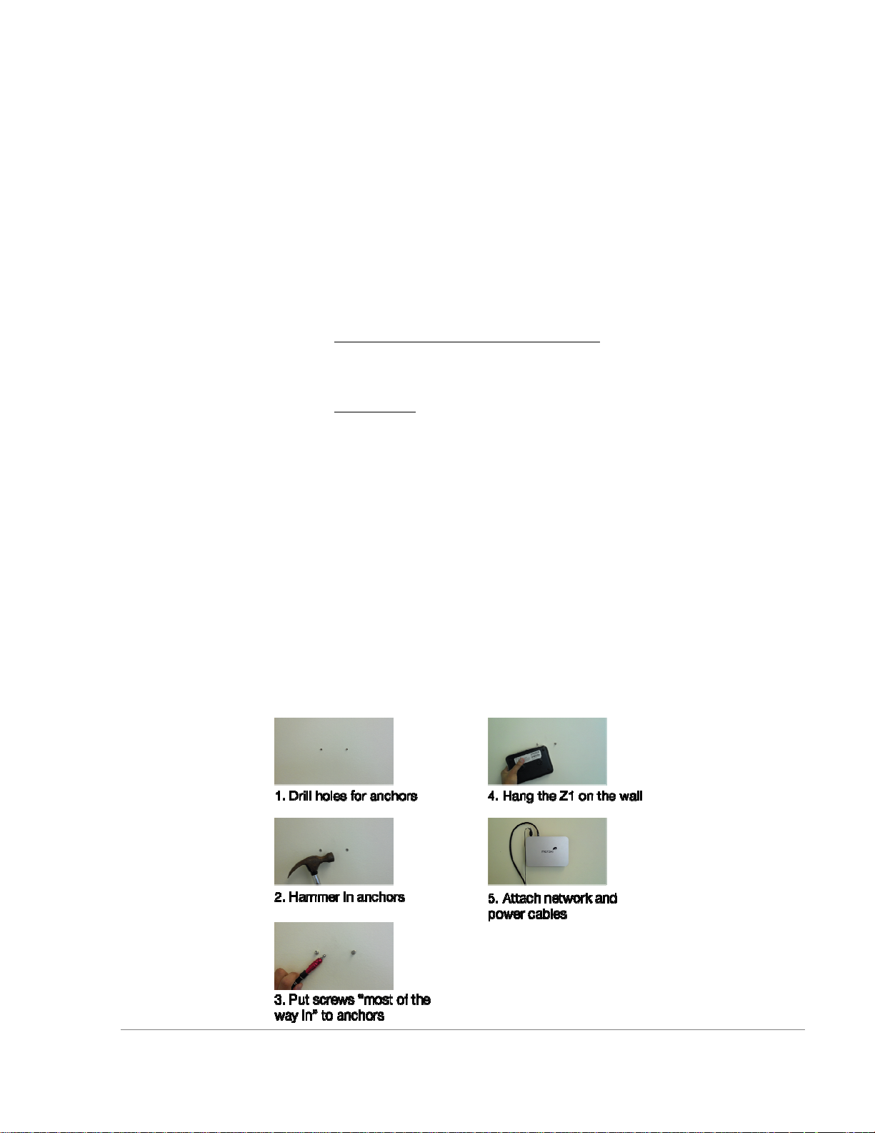
2.4.2 Wall (Instructions for Drywall/hollow wall installation)
Material Included in “Wall Mounting hardware”:
4 wall anchors.
4 wall mounting screws.
Tools needed:
Phillips screwdriver
Hammer
Drill with 1⁄4 inch bit
It is recommended to install the Z1 so the logo is oriented “right side
up”. However the mounting crosses on the base support upside down or
right angle orientations as well.
1. Drill 2 1/4” holes in the wall, spaced 2 7/8” apart
2. Insert included Wall anchors. If you have a wall material other than
drywall, use appropriate anchors for your wall.
3. Screw in included mounting screws. Top when approximately 1/4”
of screw is showing outside the anchor material.
4. Hang the Z1 on the two mounting screw heads
5. Attach network and power cables as needed
Meraki Z1 Installation Guide Pre-Deployment Setup | 10
Page 11

3 Regulatory Information for Z1
Federal Communication Commission Interference Statement:
This equipment has been tested and found to comply with the limits for a Class B digital device, pursuant
to Part 15 of the FCC Rules. These limits are designed to provide reasonable protection against harmful
interference in a residential installation. This equipment generates, uses and can radiate radio frequency
energy and, if not installed and used in accordance with the instructions, may cause harmful interference
to radio communications. However, there is no guarantee that interference will not occur in a particular
installation. If this equipment does cause harmful interference to radio or television reception, which can be
determined by turning the equipment off and on, the user is encouraged to try to correct the interference
by one of the following measures:
• Reorient or relocate the receiving antenna.
• Increase the separation between the equipment and receiver.
• Connect the equipment into an outlet on a circuit different from that to which the receiver is connected.
• Consult the dealer or an experienced radio/TV technician for help.
FCC Caution:
Any changes or modifications not expressly approved by the party responsible for compliance could void
the user’s authority to operate this equipment. This device complies with Part 15 of the FCC Rules.
Operation is subject to the following two conditions:
• this device may not cause harmful interference, and
• this device must accept any interference received, including interference that may cause undesired
operation.
FCC Radiation Exposure Statement:
This equipment complies with FCC radiation exposure limits set forth for an uncontrolled environment.This
equipment should be installed and operated with minimum distance 20 cm between the radiator and your
body. This transmitter must not be co-located or operating in conjunction with any other antenna or
transmitter.IEEE 802.11b or 802.11g operation of this product in the USA is firmware-limited to channels 1
through 11
Operations in the 5.15-5.25GHz band are restricted to indoor usage only. This transmitter must not be colocated or operating in conjunction with any other antenna or transmitter. Note: The country code selection
is for non-US model only and is not available to all US model. Per FCC regulation, all WiFi product
marketed in US must fixed to US operation channels only.
Brazil Regulatory Wireless Notice:
This equipment must be installed and configured by professional networking personnel only. Network
clients or users are not intended to install, configure, or operate the equipment directly.
Canadian Regulatory Wireless Notice (IC ID: 6961A-60024010):
This device complies with RSS-210 of the Industry Canada Rules. Operation is subject to the following two
conditions:
• this device may not cause interference and
• this device must accept any interference, including interference that may cause undesired operation of
the device.
Ce dispositif est conforme à la norme CNR-210 d’Industrie Canada applicable aux appareils radio exempts
de licence.Son fonctionnement est sujet aux deux conditions suivantes:
Meraki Z1 Installation Guide Regulatory Information for Z1 | 11
Page 12

• le dispositif ne doit pas produire de brouillage préjudiciable, et
• ce dispositif doit accepter tout brouillage reçu, y compris un brouillage susceptible de provoquer un
fonctionnement indésirable.
Radio Frequency (RF) Exposure Information
The radiated output power of the Wireless Device is below the Industry Canada (IC) radio frequency
exposure limits. The Wireless Device should be used in such a manner such that the potential for human
contact during normal operation is minimized.
This device has also been evaluated and shown compliant with the IC RF Exposure limits under mobile
exposure conditions. (antennas are greater than 20cm from a person's body).
Informations concernant l'exposition aux fréquences radio (RF)
La puissance de sortie émise par l’appareil de sans fil est inférieure à la limite d'exposition aux fréquences
radio d'Industry Canada (IC). Utilisez l’appareil de sans fil de façon à minimiser les contacts humains lors
du fonctionnement normal.
Ce périphérique a également été évalué et démontré conforme aux limites d'exposition aux RF d'IC dans
des conditions d'exposition à des appareils mobiles (les antennes se situent à moins de 20 cm du corps
d'une personne).
Important Notice:
(i) The device for operation in the band 5150-5250 MHz is only for indoor use to reduce the potential for
harmful interference to co-channel mobile satellite systems;
(ii) The maximum antenna gain permitted for devices in the band 5725-5825 MHz shall comply with the
e.i.r.p. limits specified for point-to-point and non point-to-point operation as appropriate.
Note Importante:
(i) L’appareil dans la bande 5150-5250 MHz est seulement pour utilisation à l’intérieur d’un bâtiment pour
réduire le risque de brouillage apporté aux systèmes de satellite mobile;
(ii) Le gain d’antenne maximal autorisé pour les appareils dans les bandes 5725-5825 MHz doivent
respecter la limite e.i.r.p., ainsi que les limites pour les opérations point-à-point et non-point-à-point, le cas
échéant;
IC Radiation Exposure Statement:
This equipment complies with IC radiation exposure limits set forth for an uncontrolled environment.This
equipment should be installed and operated with minimum distance 20 cm between the radiator and your
body.
NOTE IMPORTANTE: (Pour l’utilisation de dispositifs mobiles)
Déclaration d’exposition aux radiations:
Cet équipement est conforme aux limites d’exposition aux rayonnements IC établies pour un
environnement non contrôlé.
Meraki Z1 Installation Guide Regulatory Information for Z1 | 12
Page 13

Cet équipement doit être installé et utilisé avec un minimum de 20 cm de distance entre la source de
rayonnement etvotre corps.
Europe – EU Declaration of Conformity
This device complies with the essential requirements of the R&TTE Directive 1999/5/EC.The following
test methods have been applied in order to prove presumption of conformity with the essential
requirements of the R&TTE Directive 1999/5/EC:
Radio: EN 300 328, EN 301 893
EMC: EN 301 489-1, EN 301 489-17
Safety: EN 60950-1
RF Exposure: EN 50385
Emissions: EN 55022
Immunity: EN 61000-4-2, EN 61000-4-3, EN 61000-4-4, EN 61000-4-5, EN 61000-4-6
This device is a 2.4 GHz and 5 GHz wideband transmission system (transceiver), intended for use in all
EU member states and EFTA countries with the following restrictions:
In Italy the end-user should apply for a license at the national spectrum authorities in order to obtain
authorization to use the device for setting up outdoor radio links and/or for supplying public access to
telecommunications and/or network services.
The device may not be used in the 5 GHz spectrum unless the 5.725 - 5.875 GHz has been disabled. This
can be done through the Meraki Dashboard.
In Italy the end-user should apply for a license at the national spectrum authorities in order to obtain
authorization to use the device for setting up outdoor radio links and/or for supplying public access to
telecommunications and/or network services.
Cesky (Czech) Meraki, Inc. tímto prohlašuje, že tento wireless device je ve shode se základními
požadavky a dalšími príslušnými ustanoveními smernice.
Dansk (Danish) Undertegnede Meraki, Inc. erklærer herved, at følgende udstyr wireless device overholder
de væsentlige krav og øvrige relevante krav i direktiv 1999/5/EF.
Deutsch (German) Hiermit erklärt Meraki, Inc., dass sich das Gerät wireless device in Übereinstimmung
mitden grundlegenden Anforderungen und den übrigen einschlägigen Bestimmungen der Richtlinie
1999/5/EG befi ndet.
Eesti (Estonian) Käesolevaga kinnitab Meraki, Inc. seadme wireless device vastavust direktiivi 1999/5/EÜ
põhinõuetele ja nimetatud direktiivist tulenevatele.
English Hereby, Meraki, Inc., declares that this wireless device is in compliance with the essential
requirements and other relevant provisions of Directive 1999/5/EC.
Español (Spanish) Por medio de la presente Meraki, Inc. declara que el wireless device cumple con los
requisitos esenciales y cualesquiera otras disposiciones aplicables o exigibles de la Directiva 1999/5/CE.
Français (French) Par la présente Meraki, Inc. déclare que l’appareil wireless device est conforme aux
exigences essentielles et aux autres dispositions pertinentes de la directive 1999/5/CE.
Italiano (Italian) Con la presente Meraki, Inc. dichiara che questo wireless device è conforme ai requisiti
essenzialied alle altre disposizioni pertinenti stabilite dalla direttiva 1999/5/CE.
Latviski (Latvian) Ar šo Meraki, Inc. deklar_, ka wireless device atbilst Direkt_vas 1999/5/EK b_tiskaj_m
pras_b_m un citiem ar to saist_tajiem noteikumiem.
Lietuvi_ (Lithuanian) Šiuo Meraki, Inc. deklaruoja, kad šis wireless device atitinka esminius reikalavimus ir
kitas 1999/5/EB Direktyvos nuostatas.
Meraki Z1 Installation Guide Regulatory Information for Z1 | 13
Page 14

Nederland (Dutch) Hierbij verklaart Meraki, Inc. dat het toestel wireless device in overeenstemming is met
de essentiële eisen en de andere relevante bepalingen van richtlijn 1999/5/EG.
Malti (Maltese) Hawnhekk, Meraki, Inc., jiddikjara li dan wireless device jikkonforma mal-_tigijiet essenzjali
u ma provvedimenti o_rajn relevanti li hemm fi d-Dirrettiva 1999/5/EC.
Magyar (Hungarian) Alulírott, Meraki, Inc. nyilatkozom, hogy a wireless devicce megfelel a vonatkozó
alapvetõ követelményeknek és az 1999/5/EC irányelv egyéb elõírásainak.
Polski (Polish) Niniejszym Meraki, Inc. o_wiadcza, _e wireless device jest zgodny z zasadniczymi
wymogami oraz pozostalymi stosownymi
Português (Portuguese) Meraki, Inc. declara que este wireless device está conforme com os requisitos
essenciais e outras disposições da Directiva 1999/5/CE.
Slovensko (Slovenian) Meraki, Inc. izjavlja, da je ta wireless device v skladu z bistvenimi zahtevami in
ostalimi relevantnimi dolocili direktive 1999/5/ES.
Slovensky (Slovak) Meraki, Inc. týmto vyhlasuje, že wireless device splna základné požiadavky a všetky
príslušné ustanovenia Smernice 1999/5/ES.
Suomi (Finnish) Meraki, Inc. vakuuttaa täten että wireless device tyyppinen laite on direktiivin 1999/5/EY
oleellisten vaatimusten ja sitä koskevien direktiivin muiden ehtojen mukainen.
Svenska (Swedish) Härmed intygar Meraki, Inc. att denna wireless device står I överensstämmelse med
de väsentliga egenskapskrav och övriga relevanta bestämmelser som framgår direktiv 1995/5/EG.
Meraki Z1 Installation Guide Regulatory Information for Z1 | 14
 Loading...