

Page 1
Catalyst 6000 Family Content Switching Module
Installation and Configuration Note
Product Number: WS-X6066-SLB-APC
This publication contains the procedures for installing and configuring the Catalyst 6000 family Content
Switching Module (CSM).
This publication does not contain the instructions to install the Catalyst 6000 family switch chassis. For
information on installing the switch chassis, refer to the Catalyst 6000 Family Installation Guide.
Note For translations of the warnings in this publication, see the “Translated Safety Warnings” section on
Contents
page 54.
This publication consists of these sections:
• Overview, page 2
• Safety Overview, page 8
• System Requirements, page 9
• Required Tools, page 11
• Installing the Content Switching Module, page 11
• Verifying the Installation, page 15
• Upgrading to a New Software Release, page 16
• Configuring the Content Switching Module, page 19
• Writing and Restoring Configurations, page 34
• Configuration Examples, page 35
• Configuring Probes for Health Monitoring, page 46
• Configuring Route Health Injection, page 51
Corporate Headquarters:
Cisco Systems, Inc., 170 West Tasman Drive, San Jose, CA 95134-1706 USA
Copyright © 2001. Cisco Systems, Inc. All rights reserved.
Page 2

Overview
Overview
• Regulatory Standards Compliance, page 54
• Translated Safety Warnings, page 54
• Related Documentation, page 58
• Obtaining Documentation, page 59
• Obtaining Technical Assistance, page 60
The CSM provides high-performance connections between network devices and server farms (groups of
real servers) based on Layer 4 through 7 packet information. Clients connect to the CSM by supplying
the virtual IP address (VIP) of the virtual server. The CSM is configured to handle VIP address
connections. When a client initiates a connection to the virtual server, the CSM chooses a real server (a
physical device that is assigned to a server farm) for the connection based on configured load-balancing
algorithms and policies.
Representing server farms as virtual servers facilitates scalability and availability. The addition of new
servers and the removal or failure of existing servers can occur at any time without affecting the virtual
server’s availability.
Sticky connections limit traffic to individual servers. These connections are configured so that multiple
connections from the same client are stuck to the same real server using source IP addresses, source IP
subnets, cookies, secure socket layer (SSL), or redirected using the Hypertext Transfer Protocol (HTTP)
requests. Policies manage traffic by defining where to send client requests for information Configuring
server load balancing requires that you know the following:
• Network topology you are using in your installation.
• Real server IP addresses.
• The Domain Name Server (DNS) must have an entry for the CSM VIPs (if you want them to be
reached through names).
• Each virtual server’s IP address.
Note You cannot run Cisco IOS server load balancing software on the same switch as the CSM.
Note The CSM runs on Cisco IOS Release 12.1(6)E or later. If you are using a Supervisor Engine 2, you
must use Cisco IOS Release 12.1(8a)E or later. For more information, see the “System
Requirements” section on page 9.
Caution You can use the Multilayer Switch Feature Card (MSFC), internal to the Catalyst 6000 family switch,
to route traffic on either the client side or the server side of the CSM, but not both simultaneously.
Caution The WS-X6066-SLB-APC Content Switching Module is not fabric enabled.
Catalyst 6000 Family Content Switching Module Installation and Configuration Note
2
78-11631-02 Rev. A0
Page 3

Features
Overview
These sections describe the CSM:
• Features, page 3
• Front Panel Description, page 4
• Operation Mode, page 5
• Client-to-CSM-to-Server Traffic Flow, page 7
Table 1 describes the features of the CSM.
Table 1 Content Switching Module Features
Feature Description
Management Standard Cisco IOS command-line interface
Management interface integrated with host platform
Load-Balancing Algorithms Weighted round-robin
Weighted least connections
Connection high/low watermarks
Source address-based hashing algorithm
Flow and URL Identification URL regular expression match
Cookie regular expression match
1
SSL
session ID match
Source IP address
Standard ACLs
Security Source IP address and URL expression match and AC entry match
Statistics Packets through normal and special switching
Connections created, established, destroyed, current, and timed out
Failed server connections
Layer 4 load-balanced decisions and rejected connections
Layer 7 load-balanced decisions and rejected connections
Layer 4 and Layer 7 rejected connections
Checksum failures
Redirect and FTP connections
MAC frames
78-11631-02 Rev. A0
Catalyst 6000 Family Content Switching Module Installation and Configuration Note
3
Page 4
Overview
Table 1 Content Switching Module Features (continued)
Feature Description
Health Monitoring TCP, HTTP, ICMP, Telnet, FTP
Other Features SSL session ID, cookie and source IP address-based sticky
1. SSL = Secure Socket Layer
2. MTU = Maximum Transmission Unit
Front Panel Description
connections
Fragmented IP frames support
2
MTU
of 9000
Load and availability reporting supporting remote monitoring and
management
High availability preventing service disruptions
Redundant modules configured for fault-tolerance support
Status LED
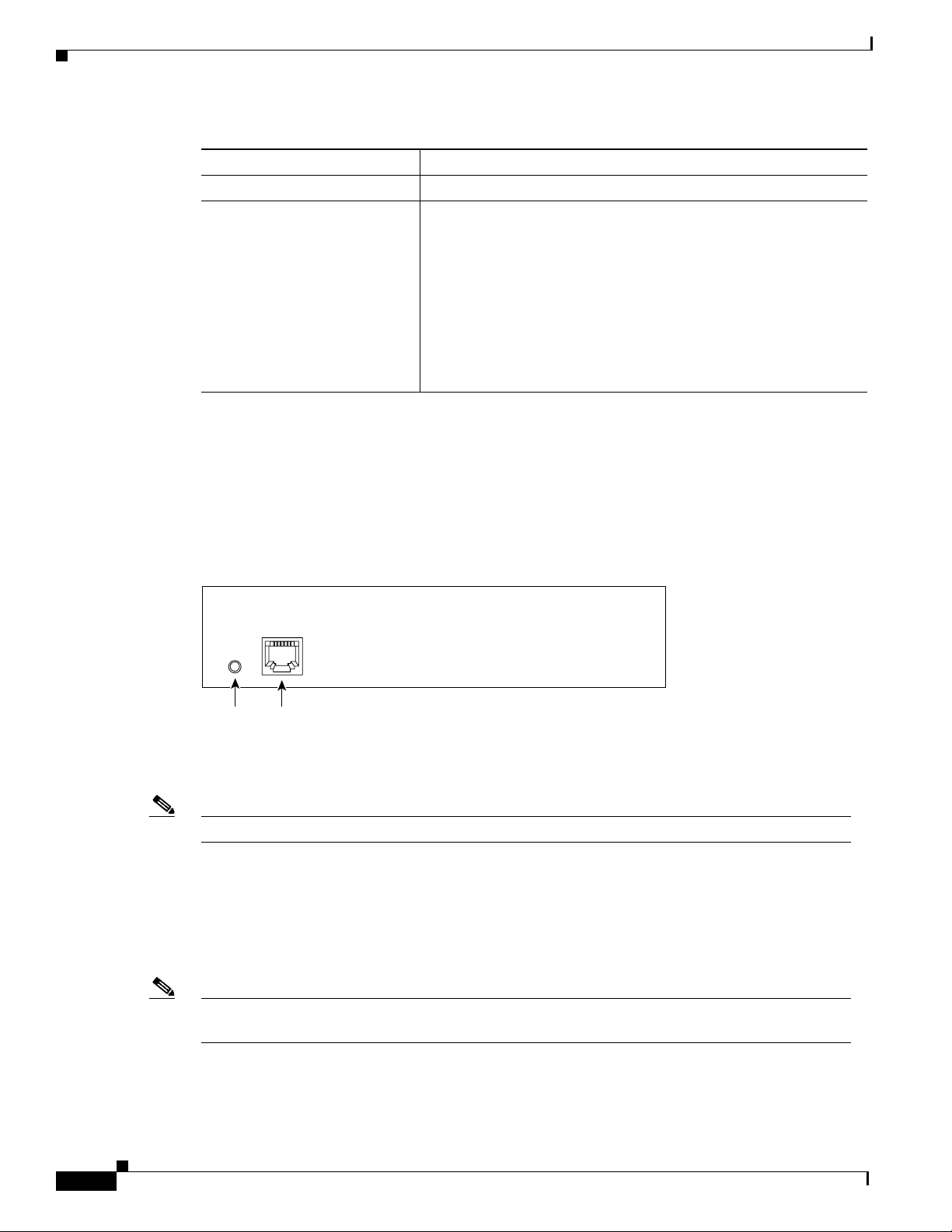
The CSM front panel features are shown in Figure 1.
Figure 1 Content Switching Module Front Panel
Status
LED
Note The RJ-45 connector is covered by a removable plate.
RJ-45 (Test)
connector
When the CSM powers up, it initializes various hardware components and communicates with the
supervisor engine. The Status LED on the CSM shows the dialog with the supervisor engine and the
results of the initialization.
CSG
47525
Note For more information on the supervisor engine LEDs, refer to the Catalyst 6000 Family Module
Installation Guide.
During the normal initialization sequence, the status LED changes from Off to Red, Orange, and then
Green. Table 2 describes the status LED operation.
Catalyst 6000 Family Content Switching Module Installation and Configuration Note
4
78-11631-02 Rev. A0
Page 5

Overview
Table 2 Content Switching Module Status LED
Color Description
Off
Red • The module is released from reset by the supervisor engine and is booting.
Orange
Green
Green to Orange
1. Enter the show environment temperature mod command to display the temperature of each of four sensors on the CSM.
2. CLI = command-line interface.
• The module is waiting for the supervisor engine to grant power.
• The module is not online.
• The module is not receiving power, which could be caused by the following:
–
Power is not available to the CSM.
–
Module temperature is over the limit1.
• If the boot code fails to execute, the LED stays red after power up.
• The module is initializing hardware or communicating with the supervisor
engine.
• A fault occurred during the initialization sequence.
• If the module fails to download its Field Programmable Gate Arrays (FPGAs)
on power up, it still proceeds with the rest of the initialization sequence and
is granted module online status from the supervisor engine, but the LED stays
orange.
• If the module is not granted module online status from the supervisor engine,
the LED stays orange. This problem could be caused by the supervisor engine
detecting a failure in an external loopback test that it issued to the CSM.
• The module is operational; the supervisor engine has granted module online
status.
• The module is disabled through the supervisor engine CLI
2
using the set
module disable mod command.
RJ-45 Connector
The RJ-45 connector on the front panel provides a connection point for a management station or test
device. The RJ-45 connector is covered by a removable plate. Typically, this connector is used by field
engineers to perform testing and to obtain dump information.
Operation Mode
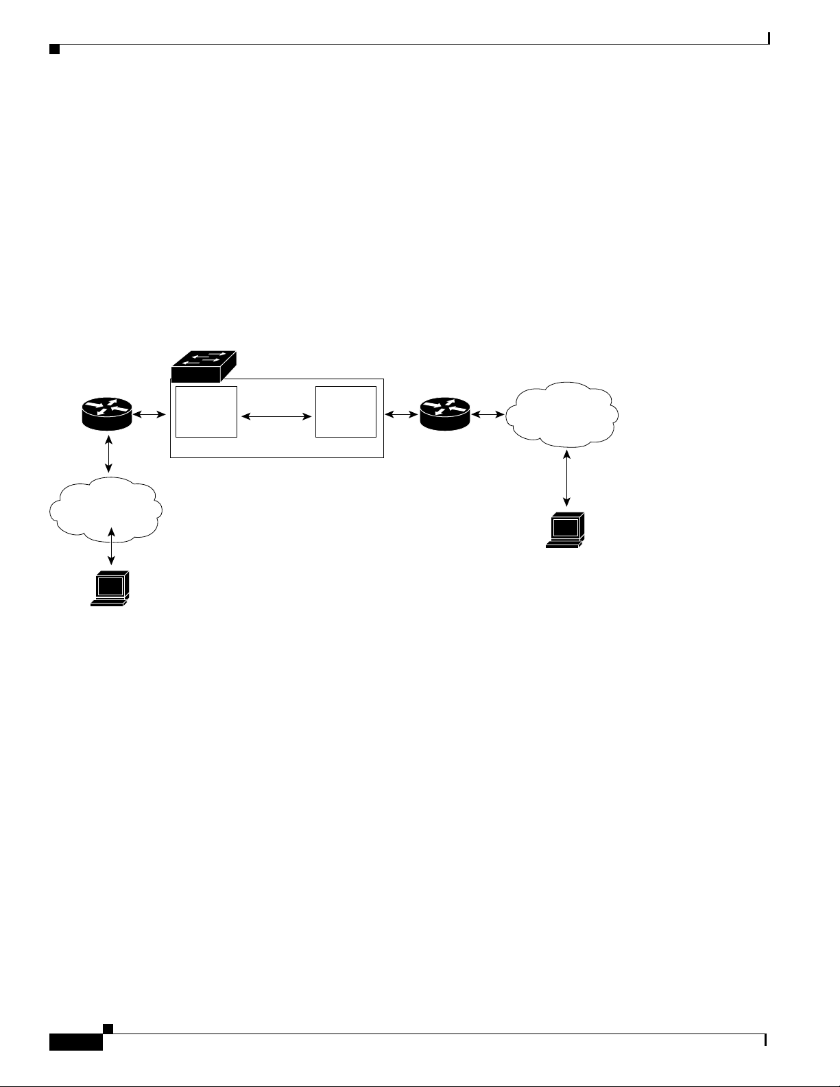
Clients and servers communicate through the CSM using Layer 2 and Layer 3 technology in a specific
VLAN configuration. (See Figure 2.) Clients connect to the client side VLAN and servers connect to the
server side VLAN. Servers and clients can exist on different subnets. Servers can also be located one or
more Layer 3 hops away and connect to the server-side VLAN through routers.
A client sends a request that arrives on one of the module’s VIP addresses. The CSM forwards this
request to a server that can satisfy the request. The server then forwards the response to the CSM. The
CSM forwards the response to the client.
78-11631-02 Rev. A0
Catalyst 6000 Family Content Switching Module Installation and Configuration Note
5
Page 6
Overview
When the client-side and server-side VLANs are on the same subnets, you can configure the CSM in
single subnet (bridge) mode. For more information, see the “Single Subnet (Bridge) Mode
Configuration” section on page 35.
When the client- and server-side VLANs are on different subnets, you can configure the CSM to operate
in a secure (router) mode. For more information, see the “Secure (Router) Mode Configuration” section
on page 37.
You can set up a fault-tolerant configuration in either the secure (router) or single subnet (bridged) mode
using redundant CSMs. For more information, see the “Fault-Tolerant Configuration” section on
page 38. Using multiple VLANs, single subnet (bridge) mode and secure (router) mode can coexist in
the same CSM.
Figure 2 Content Switching Module and Servers
Catalyst 6500 chassis
Router
Internet
Client
Content
services
gateway
4 gigabit
Switching
fabric
Internet
47527
Content
provider
Catalyst 6000 Family Content Switching Module Installation and Configuration Note
6
78-11631-02 Rev. A0
Page 7
Client-to-CSM-to-Server Traffic Flow
This section describes how the traffic flows between the client and server in a CSM environment.
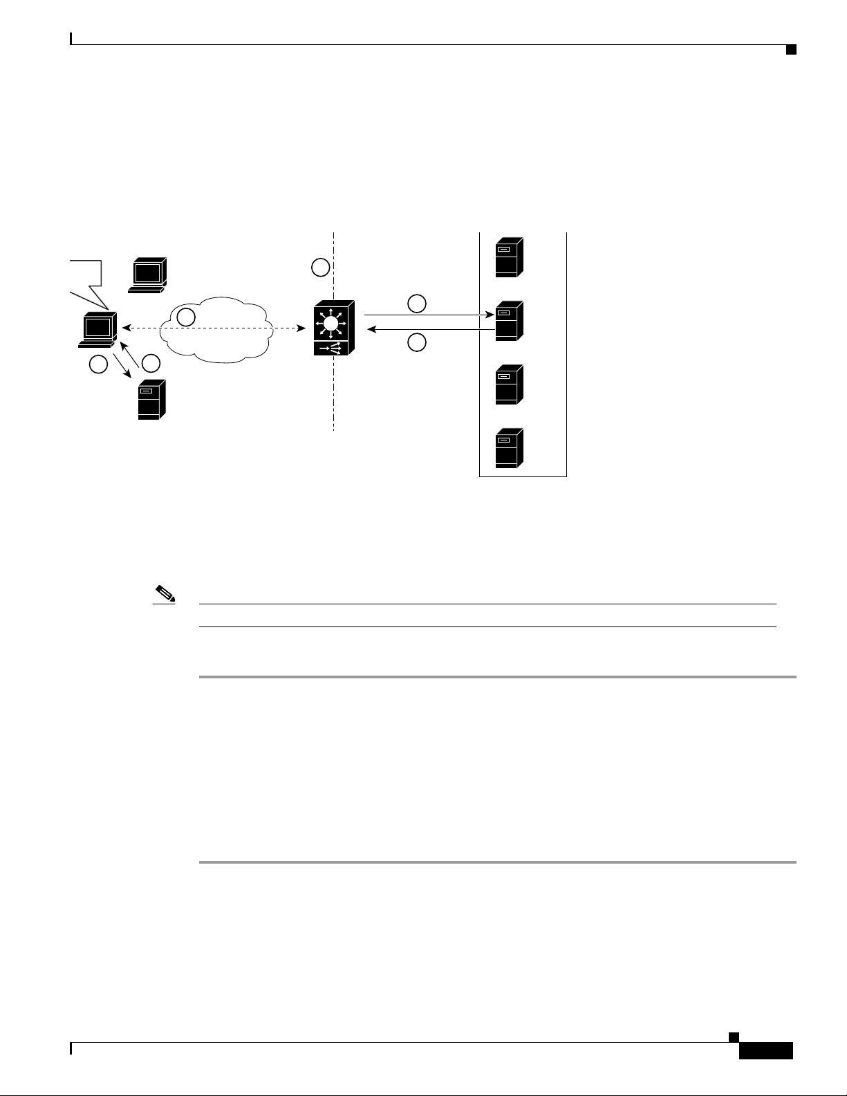
(See Figure 3.)
Figure 3 Client-to-Content Switching Module-to-Server Traffic Flow
.com
5
Overview
W
2
4
3
DNS server
Note The numbers in Figure 3 refer to the steps in the following procedure.
VIP
6
7
www.example.com
web server farm
X
Y
Z
47528
When you enter a request for information by entering a URL, the traffic flow is as follows:
Step 1 You enter a URL. (For example, in Figure 3 you enter www.fox.com.)
Step 2 The client contacts a DNS server to locate the IP address associated with the URL you entered.
Step 3 The DNS server sends the IP address of the virtual IP (VIP) to the client.
Step 4 The client uses that IP address (CSM VIP) to send the HTTP request to the CSM.
Step 5 The CSM receives the request with the URL, makes a load balancing decision, and selects a server. For
Step 6 The CSM performs the Network Address Translation (NAT).
78-11631-02 Rev. A0
example, in Figure 3, the CSM selects a server (X server) from the www.fox.com server pool, replacing
its own VIP address with the address of the X server and forwards the traffic to the X server.
Catalyst 6000 Family Content Switching Module Installation and Configuration Note
7
Page 8

Safety Overview
Safety Overview
Safety warnings appear throughout this publication in procedures that, if performed incorrectly, may
harm you. A warning symbol precedes each warning statement.
Warning
Waarschuwing
Varoitus
Attention
This warning symbol means danger. You are in a situation that could cause bodily injury. Before
you work on any equipment, be aware of the hazards involved with electrical circuitry and be
familiar with standard practices for preventing accidents. To see translations of the warnings
that appear in this publication, refer to the “Translated Safety Warnings” section in this
document.
Dit waarschuwingssymbool betekent gevaar. U verkeert in een situatie die lichamelijk letsel
kan veroorzaken. Voordat u aan enige apparatuur gaat werken, dient u zich bewust te zijn van
de bij elektrische schakelingen betrokken risico's en dient u op de hoogte te zijn van standaard
maatregelen om ongelukken te voorkomen. Voor vertalingen van de waarschuwingen die in
deze publicatie verschijnen, kunt u het gedeelte “Translated Safety Warnings” (Vertalingen van
veiligheidsvoorschriften) raadplegen in dit document.
Tämä varoitusmerkki merkitsee vaaraa. Olet tilanteessa, joka voi johtaa ruumiinvammaan.
Ennen kuin työskentelet minkään laitteiston parissa, ota selvää sähkökytkentöihin liittyvistä
vaaroista ja tavanomaisista onnettomuuksien ehkäisykeinoista. Tässä julkaisussa esiintyvien
varoitusten käännökset löydät tämän asiakirjan "Translated Safety Warnings" (käännetyt
turvallisuutta koskevat varoitukset).
Ce symbole d'avertissement indique un danger. Vous vous trouvez dans une situation pouvant
causer des blessures ou des dommages corporels. Avant de travailler sur un équipement, soyez
conscient des dangers posés par les circuits électriques et familiarisez-vous avec les
procédures couramment utilisées pour éviter les accidents. Pour prendre connaissance des
traductions d’avertissements figurant dans cette publication, consultez la section « Translated
Safety Warnings » (Traduction des avis de sécurité) de ce document.
8
Warnung
Avvertenza
Advarsel
Catalyst 6000 Family Content Switching Module Installation and Configuration Note
Dieses Warnsymbol bedeutet Gefahr. Sie befinden sich in einer Situation, die zu einer
Körperverletzung führen könnte. Bevor Sie mit der Arbeit an irgendeinem Gerät beginnen, seien
Sie sich der mit elektrischen Stromkreisen verbundenen Gefahren und der Standardpraktiken
zur Vermeidung von Unfällen bewußt. Übersetzungen der in dieser Veröffentlichung enthaltenen
Warnhinweise finden Sie im Abschnitt “Translated Safety Warnings” (Übersetzung der
Warnhinweise) in diesem Dokument.
Questo simbolo di avvertenza indica un pericolo. La situazione potrebbe causare infortuni alle
persone. Prima di lavorare su qualsiasi apparecchiatura, occorre conoscere i pericoli relativi
ai circuiti elettrici ed essere al corrente delle pratiche standard per la prevenzione di incidenti.
La traduzione delle avvertenze riportate in questa pubblicazione si trova nella documento
“Translated Safety Warnings” (Traduzione delle avvertenze di sicurezza) nel presente
documento.
Dette varselsymbolet betyr fare. Du befinner deg i en situasjon som kan føre til personskade. Før
du utfører arbeid på utstyr, må du vare oppmerksom på de faremomentene som elektriske kretser
innebærer, samt gjøre deg kjent med vanlig praksis når det gjelder å unngå ulykker. Hvis du vil
se oversettelser av de advarslene som finnes i denne publikasjonen, kan du se i avsnittet
"Translated Safety Warnings" [Oversatte sikkerhetsadvarsler] i dette dokumentet.
78-11631-02 Rev. A0
Page 9
System Requirements
Aviso
¡Advertencia!
Varning!
Warning
Este símbolo de aviso indica perigo. Encontra-se numa situação que lhe poderá causar danos
físicos. Antes de começar a trabalhar com qualquer equipamento, familiarize-se com os perigos
relacionados com circuitos eléctricos, e com quaisquer práticas comuns que possam prevenir
possíveis acidentes. Para ver as traduções dos avisos que constam desta publicação, consulte
a secção “Translated Safety Warnings” - “Traduções dos Avisos de Segurança” neste
documento.
Este símbolo de aviso significa peligro. Existe riesgo para su integridad física. Antes de
manipular cualquier equipo, considerar los riesgos que entraña la corriente eléctrica y
familiarizarse con los procedimientos estándar de prevención de accidentes. Para ver una
traducción de las advertencias que aparecen en esta publicación, consultar la sección titulada
“Translated Safety Warnings” que aparece en este documento.
Denna varningssymbol signalerar fara. Du befinner dig i en situation som kan leda till
personskada. Innan du utför arbete på någon utrustning måste du vara medveten om farorna med
elkretsar och känna till vanligt förfarande för att förebygga skador. Om du vill se översättningar
av de varningar som visas i denna publikation, se avsnittet "Translated Safety Warnings"
[Översatta säkerhetsvarningar] i detta dokument.
Before you install, operate, or service the system, read the Site Preparation and Safety Guide. This
guide contains important safety information you should know before working with the system.
Warning
Only trained and qualified personnel should be allowed to install or replace this equipment.
System Requirements
Before you install the CSM into the Catalyst 6000 family switch, make sure your Catalyst 6000 family
switch meets the hardware and software requirements listed in this section.
Caution You cannot run Cisco IOS server load-balancing software on the same switch as the CSM.
Caution You can use the MSFC, internal to the Catalyst 6000 family switch, to route traffic on either the client
side or the server side of the CSM, but not both simultaneously.
Memory Requirements
The CSM memory is not configurable.
78-11631-02 Rev. A0
Catalyst 6000 Family Content Switching Module Installation and Configuration Note
9
Page 10
System Requirements
Hardware Supported
Before you can use the CSM, you must have a Supervisor Engine 1A with an MSFC and a Policy Feature
Card (PFC), or a Supervisor Engine 2 with an MSFC, and any module with ports to connect server and
client networks. The PFC is required for the VLAN access control list (VACL) capture functionality.
Caution The WS-X6066-SLB-APC Content Switching Module is not fabric enabled.
Minimum
Product Number Product Description
Content Switching Module
WS-X6066-SLB-APC with
Supervisor Engine 1A
WS-X6066-SLB-APC with
Supervisor Engine 1A
WS-X6066-SLB-APC with
Supervisor Engine 2
Console Cable
72-876-01 Console Cable Not applicable Not applicable Not applicable
Accessory Kit
800-05097-01 Accessory kit (contains the Console
Content Switching Module 1.1(1) 1.1(1) or higher 12.1(6)E or
Content Switching Module 1.1(1) 1.2(1) or higher 12.1(8)E
Content Switching Module 1.2(1) 1.2(1) 12.1(8a)E
Cable)
Software Version
Not applicable Not applicable Not applicable
Recommended
Software Version IOS Release
12.1(7)E
Environmental Requirements
The CSM operates in temperatures from 0o to 40o C (32o to 104o F). The module can withstand, without
damage, nonoperating temperatures from –40
The CSM can operate in relative humidity from 10 to 90 percent (noncondensing) and can withstand,
without damage, nonoperating relative humidity of 5 to 95 percent (noncondensing).
o
to 70o C (–40o to 158o F).
Power Requirements
You can place the CSM in any slot in the Catalyst 6000 family chassis except for the slots occupied by
the supervisor engine and the standby supervisor engine. The CSM operates on power supplied by the
chassis.
Note Slot 1 is reserved for the supervisor engine. Slot 2 can contain an additional supervisor
Catalyst 6000 Family Content Switching Module Installation and Configuration Note
10
engine in case the supervisor engine in slot 1 fails. If a redundant supervisor engine is not
required, you can insert the CSM in slots 2 through 6 on the 6-slot chassis, in slots 2 through
9 on a 9-slot chassis, or slots 2 through 13 on the 13-slot chassis.
78-11631-02 Rev. A0
Page 11
Required Tools
Software Requirements
Catalyst 6000 family CSM software release 1.1(1) requires Cisco IOS Release 12.1(6)E or 12.1(7)E.
Catalyst 6000 family CSM software release 1.2(1) requires Cisco IOS Release 12.1(8a)E or later only.
CSM Software
Release Software Part Number Hardware Cisco IOS Release Added Features
1.1(1) SC6k-SLB-APC-1.1 Supervisor Engine 1A with MSFC
and PFC
1.2(1) SC6K-1.2-CSM Supervisor Engine 1A with MSFC
and PFC
1.2(1) SC6K-1.2-CSM Supervisor Engine 2 Module with
MSFC 2
12.1(6)E or
12.1(7)E
12.1(8a)E Supervisor Engine 2
12.1(8a)E Supervisor Engine 2
Initial Release
support
support
Required Tools
This section describes the tools and requirements you need to install the CSM.
Note Before installing the CSM, you must install the Catalyst 6000 family switch chassis and at least one
supervisor engine. For information on installing the switch chassis, refer to the Catalyst 6000 Family
Installation Guide.
These tools are required to install the CSM into the Catalyst 6000 family switch:
• Flat-blade screwdriver
• Wrist strap or other grounding device
• Antistatic mat or antistatic foam
Caution Whenever you handle the supervisor engine or switching modules, always use a wrist strap or other
grounding device to prevent electrostatic discharge (ESD). See the “Installing the Content Switching
Module” section on page 11 for more information.
Installing the Content Switching Module
To install the CSM into the Catalyst 6000 family switch, perform the steps in the following sections:
• Preparing to Install the CSM, page 11
• Installing the CSM, page 12
• Verifying the Installation, page 15
Preparing to Install the CSM
Before installing the CSM, make sure that the following are available:
78-11631-02 Rev. A0
Catalyst 6000 Family Content Switching Module Installation and Configuration Note
11
Page 12

Installing the Content Switching Module
• Catalyst 6000 family switch chassis
• Servers that are connected to the Catalyst 6000 family switch through a bridged or a routed
connection
• Management station that is available through a Telnet or a console connection to perform
configuration tasks
Installing the CSM
This section describes how to install the CSM into the Catalyst 6000 family switch.
Note All modules, including the supervisor engine (if you have redundant supervisor engines), support hot
swapping. You can add, replace, or remove modules without interrupting the system power or causing
other software or interfaces to shut down. For more information about hot-swapping modules, refer
to the Catalyst 6000 Family Module Installation Guide.
To install the CSM into the Catalyst 6000 family switch, perform these steps:
Step 1 Make sure you take the necessary precautions to prevent ESD damage.
Warning
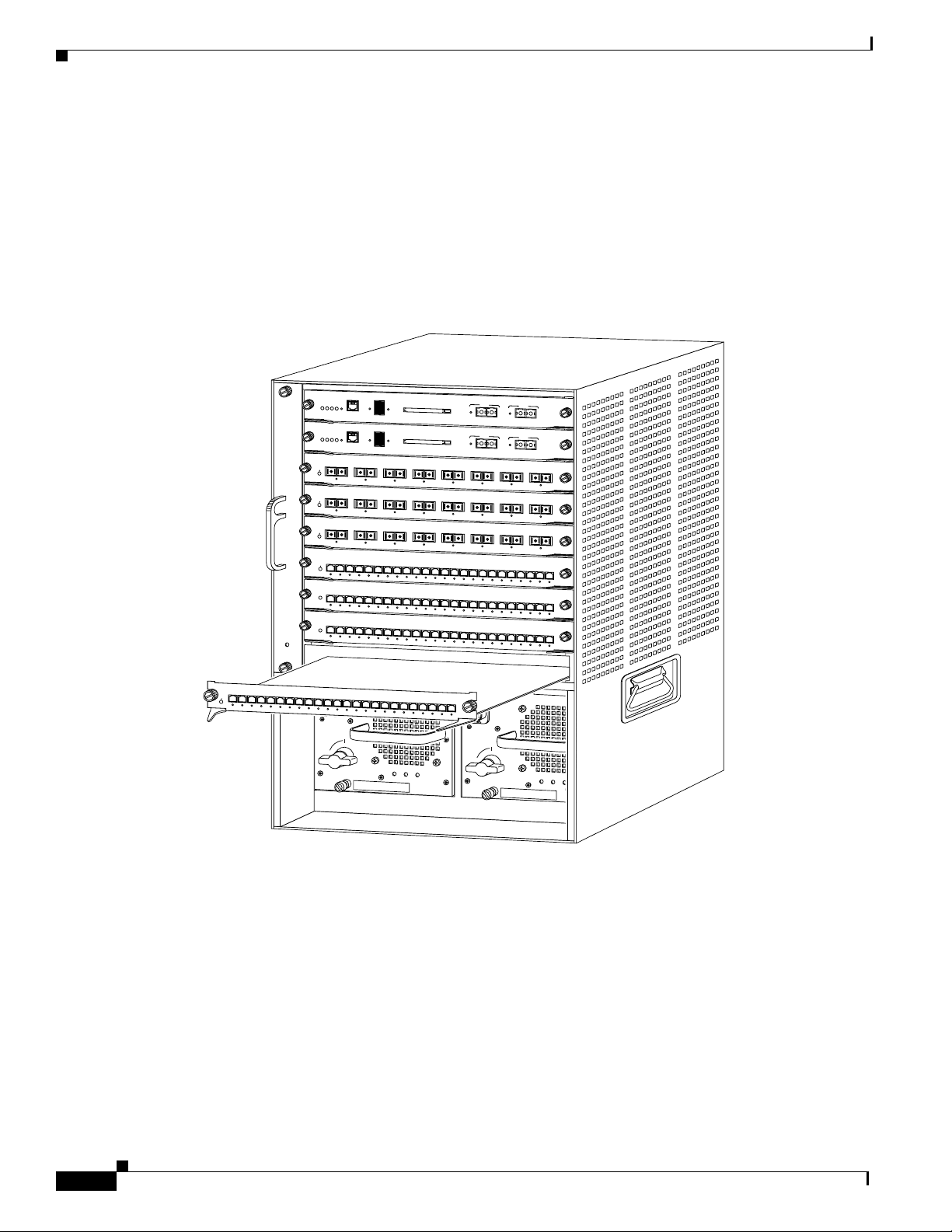
Step 2 Choose a slot for the CSM. See Figure 4 for slot numbers on a Catalyst 6000 family switch.
During this procedure, wear grounding wrist straps to avoid ESD damage to the card. Do not
directly touch the backplane with your hand or any metal tool, or you could shock yourself.
Note Slot 1 is reserved for the supervisor engine. Slot 2 can contain an additional supervisor
engine in case the supervisor engine in slot 1 fails. If a redundant supervisor engine is not
required, you can insert the CSM in slots 2 through 9 on a 9-slot chassis, or slots 2 through
6 on the 6-slot chassis, or slots 2 through 13 on the 13-slot chassis.
12
Catalyst 6000 Family Content Switching Module Installation and Configuration Note
78-11631-02 Rev. A0
Page 13
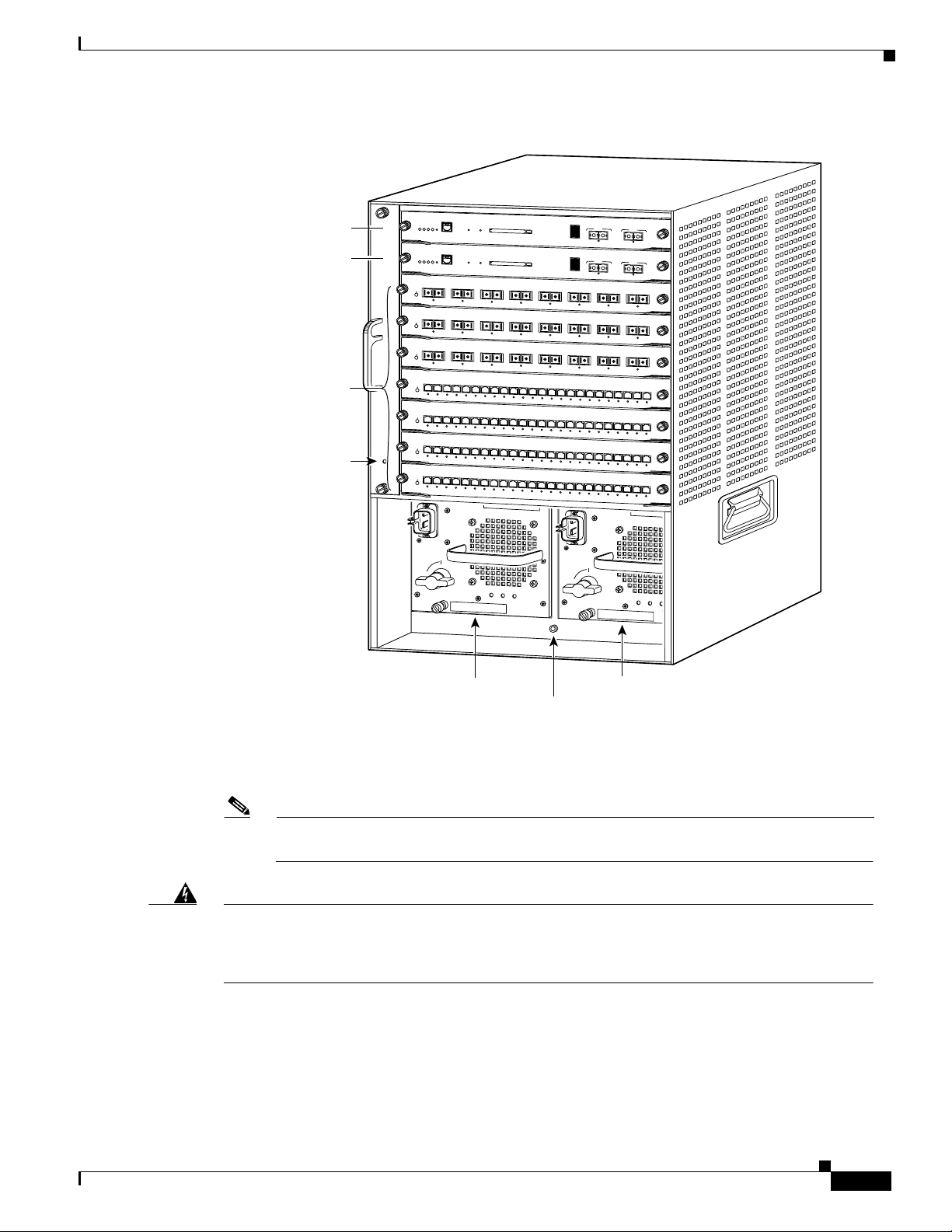
Figure 4 Slot Numbers on Catalyst 6000 Family Switches
WS-X6K-SUP2-2GE
T
E
M
L
S
Supervisor engine
Redundant supervisor
engine
Switching
modules
Fan
assembly
STATUS
M
G
O
U
E
M
T
S
T
T
E
A
N
R
S
S
T
Y
O
W
E
S
S
C
P
C
O
N
S
R
O
L
E
P
O
R
1
SUPERVISOR2
WS-X6K-SUP2-2GE
2
SUPERVISOR2
W
S-X6408
STATUS
3
8 PORT GIG
ABIT ETH
W
S-X64
08
4
STATUS
8 PORT GIG
ABIT
ETHERNET
W
S-X6408
STATU
5
8 PO
RT G
IGABIT ETHER
W
S
X
6
2
2
4
6
S
2
4 P
O
R
T
1
0
0
F
X
W
S
X
6
2
2
4
S
7
2
4 P
O
R
T
10
0
F
X
W
S
X
6
2
2
4
S
8
FAN
2
4
P
O
R
T
1
0
0
F
X
W
S
-X
6
2
2
4
S
9
2
4
P
O
R
T
1
0
0
F
X
T
M
O
D
E
C
O
N
S
O
L
E
T
E
M
L
S
M
G
O
U
E
M
T
S
T
T
E
A
N
R
S
S
T
Y
O
W
E
S
S
C
P
C
R
C
O
N
S
O
LE
1
ERNET
K
IN
L
1
LINK
1
S
NET
LINK
1
S
2
3
U
4
T
A
T
LINK
LINK
LINK
LINK
S
1
U
2
3
T
4
A
T
LINK
LINK
LINK
LINK
1
S
2
3
U
4
T
A
T
LINK
LINK
LINK
LINK
1
2
S
3
4
U
T
A
T
K
K
K
IN
IN
L
IN
L
IN
L
L
P
C
M
C
IA E
O
N
S
O
L
E
P
O
R
T
M
O
D
E
P
C
M
C
IA E
2
3
K
N
I
L
2
K
LIN
2
K
LIN
5
LINK
5
LINK
5
LINK
5
K
K
IN
L
4
K
IN
L
3
4
K
LIN
3
4
LINK
6
7
8
9
1
0
1
LINK
LINK
LINK
LINK
LINK
6
7
8
9
1
0
1
LINK
LINK
LINK
LINK
LINK
6
7
8
9
10
11
LINK
LINK
LINK
LINK
LINK
6
7
8
9
10
11
K
K
K
K
IN
K
IN
L
IN
L
IN
L
IN
L
L
S
w
itc
h
L
oa
d
10
0
%
P
O
R
T
J
E
C
T
J
E
C
T
5
K
K
N
I
L
IN
L
5
LINK
LINK
5
K
LIN
LINK
1
1
2
1
3
1
4
LINK
LINK
LINK
LINK
1
1
2
1
3
1
4
LINK
LINK
LINK
LINK
12
13
14
LINK
LINK
LINK
LINK
12
13
14
K
K
K
K
IN
IN
L
IN
L
IN
L
L
1
1
%
K
IN
L
S
w
itc
h
L
o
a
d
1
0
0%
P
O
R
T
1
1
%
K
LIN
6
7
K
K
IN
L
IN
L
6
7
LINK
LINK
6
7
LINK
LINK
1
5
1
6
1
7
1
8
1
9
2
0
LINK
LINK
LINK
LINK
LINK
LINK
1
5
1
6
1
7
1
8
1
9
2
0
LINK
LINK
LINK
LINK
LINK
LINK
15
16
17
18
19
20
LINK
LINK
LINK
LINK
LINK
LINK
15
16
17
18
19
20
K
K
K
K
IN
N
K
I
L
K
IN
L
IN
L
IN
L
IN
L
L
Installing the Content Switching Module
P
O
R
T
2
K
LIN
P
O
R
T
2
LINK
8
K
IN
L
8
LINK
8
LINK
2
1
2
2
2
3
2
4
LINK
LINK
LINK
LINK
2
1
2
2
2
3
2
4
LINK
LINK
LINK
LINK
21
22
23
24
LINK
LINK
LINK
LINK
21
22
23
24
K
K
K
K
IN
IN
L
IN
L
IN
L
L
o
INPUT
FAN
OUTPUT
OK
OK
FAIL
o
INPUT
FAN
OUTPUT
OK
OK
FAIL
16076
Power supply 1
ESD ground strap
Power supply 2
(redundant)
connector
Step 3 Check that there is enough clearance to accommodate any interface equipment that you will connect
directly to the supervisor engine or switching-module ports.
Note If possible, place switching modules between empty slots that contain only
switching-module filler plates (Cisco part number 800-00292-01).
Warning
Blank faceplates (filler panels) serve three important functions: they prevent exposure to
hazardous voltages and currents inside the chassis; they contain electromagnetic interference
(EMI) that might disrupt other equipment; and they direct the flow of cooling air through the
chassis. Do not operate the system unless all cards and faceplates are in place.
78-11631-02 Rev. A0
Catalyst 6000 Family Content Switching Module Installation and Configuration Note
13
Page 14
Installing the Content Switching Module
Step 4 Loosen the captive installation screws that secure the switching-module filler plate (or an existing
switching module) to the desired slot.
Step 5 Remove the switching-module filler plate (or an existing switching module).
Step 6 Hold the handle of the CSM with one hand, and place your other hand under the carrier support. Do not
touch the printed circuit boards or connector pins.
Step 7 Place the CSM in the slot. Align the notch on the sides of the switching-module carrier with the groove
in the slot. (See Figure 5.)
Figure 5 Installing Modules in the Catalyst 6000 Family Switch
WS-X6K-SUP1
STATUS
1
SUPERVISOR I
WS-X6K-SUP1
S
TU
STA
2
SUPERVISOR I
W
S-X6408
STATUS
3
8 PO
RT GIGABIT ETHERNET
W
S-X6408
4
STATUS
8 PORT GIGABIT ETH
ERNET
W
S-X6408
STATUS
5
8 PO
RT GIGABIT ETHERNET
W
S
X
6
2
2
4
S
U
T
A
6
T
S
2
4
P
O
R
T
1
0
0
F
X
W
S
X
6
2
2
4
S
U
T
A
T
S
7
2
4 P
O
R
T
1
0
0
F
X
W
S
X
6
2
2
4
S
U
T
A
T
S
8
2
4 P
O
R
T
1
00
F
X
FAN
LED
S
w
itc
h
L
o
a
d
1
0
0
%
D
T
E
/
SYSTEM
ACTIVE
D
C
PWR MGMT
E
RESET
C
O
N
S
O
L
E
1
%
S
w
T
1
0
0
%
D
T
E
/
SYSTEM
ACTIVE
D
C
PWR MGM
E
RESET
C
O
N
S
O
L
E
1
%
1
2
K
K
IN
N
L
I
L
1
2
LINK
LINK
1
2
LINK
LINK
1
2
3
4
5
LINK
LINK
LINK
LINK
LINK
1
2
3
4
5
K
K
K
K
IN
K
IN
L
IN
L
IN
L
IN
L
L
1
2
3
4
5
K
K
K
K
IN
K
IN
L
IN
L
IN
N
L
I
L
L
P
C
M
C
IA
itc
h
L
o
a
d
P
C
M
C
IA
3
4
K
K
IN
L
IN
L
3
4
K
LINK
LIN
3
4
K
LINK
LIN
6
7
8
9
10
11
LINK
LINK
LINK
LINK
LINK
LINK
6
7
8
9
10
11
K
K
K
K
IN
K
L
6
K
IN
L
K
IN
LIN
IN
L
IN
L
IN
L
L
7
8
9
10
11
K
K
K
K
IN
N
K
I
L
IN
L
IN
L
IN
L
L
P
O
R
T
1
P
O
R
T
E
J
E
C
T
LINK
E
J
E
C
T
LINK
5
K
IN
L
5
LINK
5
LINK
12
13
14
15
16
LINK
LINK
LINK
LINK
LINK
12
13
14
15
16
K
K
K
K
IN
K
IN
L
IN
L
IN
L
IN
L
L
12
13
14
15
16
K
K
K
K
IN
N
K
I
L
IN
L
IN
L
IN
L
L
2
LINK
P
O
R
T
1
P
O
R
T
2
LINK
6
7
K
N
I
L
6
LINK
6
LINK
17
18
LINK
17
1
8
K
IN
L
17
18
K
IN
L
8
K
K
IN
L
IN
L
7
8
LINK
LINK
7
8
LINK
LINK
19
20
21
22
23
LINK
19
K
IN
L
19
K
IN
L
24
LINK
LINK
LINK
LINK
LINK
LINK
20
21
22
23
24
K
K
K
K
IN
K
IN
L
K
N
I
L
K
IN
L
IN
L
IN
L
IN
L
L
2
0
21
22
23
24
K
K
K
K
IN
K
IN
L
IN
L
IN
N
L
I
L
L
9
WS-X6224
1
2
3
S
4
5
U
T
A
T
S
2
4
P
O
R
T
1
0
0
F
X
6
7
8
9
10
11
12
13
14
15
16
17
1
8
19
20
21
22
23
K
K
K
N
K
I
N
K
I
N
L
K
I
L
K
IN
L
K
IN
L
K
IN
L
K
IN
L
K
IN
L
K
IN
L
K
IN
L
K
IN
L
K
IN
N
L
K
I
L
K
IN
L
K
IN
L
IN
L
IN
N
L
I
L
L
o
INPUT
FAN
OK
OK
24
K
K
K
K
IN
N
K
I
N
L
K
I
L
IN
L
IN
N
L
I
L
L
o
OUTPUT
FAIL
INPUT
FAN
OUTPUT
OK
OK
FAIL
16205
14
Step 8
Keep the CSM at a 90-degree orientation to the backplane and carefully slide the CSM into the slot
until the switching-module faceplate contacts the ejector levers. (See Figure 6.)
Catalyst 6000 Family Content Switching Module Installation and Configuration Note
78-11631-02 Rev. A0
Page 15
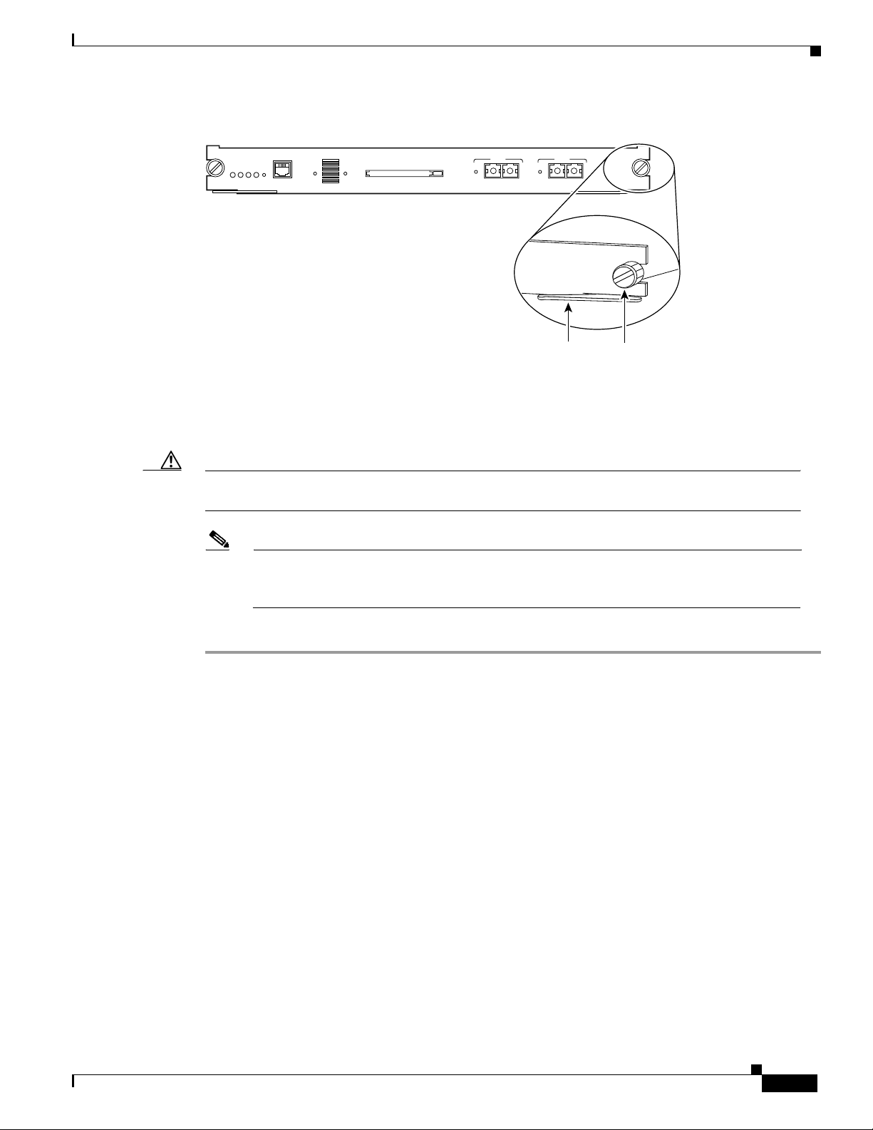
Figure 6 Ejector Levers and Captive Installation Screws
Verifying the Installation
WS-X6K-SUP1
SUPERVISOR I
STATUS
SYSTEM
ACTIVE
PWR MGMT
RESET
CONSOLE
CONSOLE
PORT
MODE
100%
Switch Load
1%
PCMCIA EJECT
LINK
PORT 1
Ejector lever
PORT 2
LINK
16059
Captive
installation
screws
Step 9 Using the thumb and forefinger of each hand, simultaneously push in the left and right levers to fully
seat the CSM in the backplane connector.
Caution Always use the ejector levers when installing or removing the CSM. A module that is partially seated
in the backplane will cause the system to halt and subsequently crash.
Note If you perform a hot swap, the console displays the message “Module n has been inserted.”
This message does not appear, however, if you are connected to the Catalyst 6000 family
switch through a Telnet session.
Step 10 Use a screwdriver to tighten the captive installation screws on the left and right ends of the CSM.
This completes the CSM installation procedure.
Verifying the Installation
When you install the CSM into the Catalyst 6000 family switch, the module goes through a boot
sequence that requires no intervention. At the successful conclusion of the boot sequence, the green
status LED will illuminate and remain on.
78-11631-02 Rev. A0
Catalyst 6000 Family Content Switching Module Installation and Configuration Note
15
Page 16

Upgrading to a New Software Release
Using the Command-Line Interface
The software interface for the CSM is the Cisco IOS interface. To understand the Cisco IOS
command-line interface and Cisco IOS command modes, refer to Chapter 2 in the Catalyst 6000 Family
IOS Software Configuration Guide.
Note Because of each prompt’s character limit, some prompts may be truncated. For example:
Router(config-slb-vlan-server)# may appear as Router(config-slb-vlan-serve)#
Accessing Online Help
In any command mode, you can get a list of available commands by entering a question mark (?) as
follows:
Router> ?
or
Router(config)# ip slb ?
Note Online help shows the default configuration values and ranges available to commands.
Upgrading to a New Software Release
This section describes the three methods on how to upgrade the CSM:
• Upgrading from the Supervisor Engine Bootflash, page 17
• Upgrading from a PCMCIA Card, page 18
• Upgrading Over the Network, page 18
Note When upgrading to a new software release, you must upgrade the CSM image before upgrading the
Cisco IOS image. Failure to do so will cause the supervisor engine to not recognize the CSM. In this
case, you would have to downgrade the Cisco IOS image, upgrade the CSM image, and then upgrade
the Cisco IOS image.
During the upgrade, enter all commands on a console connected to the supervisor engine. Enter each
configuration command on a separate line. To complete the upgrade, enter the exit command to return
to the supervisor engine prompt.
16
Catalyst 6000 Family Content Switching Module Installation and Configuration Note
78-11631-02 Rev. A0
Page 17

Caution You must enter the exit command to terminate sessions with the CSM being upgraded. If you do not
terminate the session and you remove the CSM from the Catalyst 6000 family chassis, you cannot
issue configuration commands to the CSM unless you press Ctrl + ^, enter x, and type the disconnect
command at the prompt.
Upgrading from the Supervisor Engine Bootflash
Upgrade the CSM from the supervisor engine bootflash as follows:
Note Refer to the Catalyst 6000 Family Supervisor Engine Flash PC Card Installation Note for
instructions on loading images into bootflash.
Step 1 Enable the TFTP server to supply the image from bootflash as follows:
Router>
Router> enable
Router# conf t
Router(config)# tftp-server sup-bootflash:c6slb-apc.revision-num.bin
Router(config)
Upgrading to a New Software Release
Step 2 Set up a session between the supervisor engine and the CSM:
Router# session CSM-slot-number 0
Step 3 Load the image from the supervisor engine to the CSM:
CSM> upgrade 127.0.0.zz c6slb-apc.revision-num.bin
where
zz = 12 if the supervisor engine is installed in chassis slot 1
zz = 22 if the supervisor engine is installed in chassis slot 2
Note The supervisor engine can only be installed in chassis slot 1 or slot 2.
Step 4 Reboot the CSM by power cycling the CSM or by issuing the following commands on the supervisor
engine console.
Router# config t
Router(config)# power cycle module slot-number
78-11631-02 Rev. A0
Catalyst 6000 Family Content Switching Module Installation and Configuration Note
17
Page 18

Upgrading to a New Software Release
Upgrading from a PCMCIA Card
Upgrade the CSM from a removable Flash (PCMCIA) card inserted in the supervisor engine as follows:
Step 1 Enable the TFTP server to supply the image from the removable Flash card:
Router>
Router> enable
Router# conf t
Router(config)# tftp-server slotx:c6slb-apc.revision-num.bin
where
x = 0 if the PCMCIA card is installed in supervisor engine PCMCIA slot 0.
Step 2 Set up a session between the supervisor engine and the CSM:
Router# session CSM-slot-number 0
Step 3 Load the image from the supervisor engine to the CSM:
CSM> upgrade slot0: c6slb-apc.revision-num.bin
Note The supervisor engine can only be installed in chassis slot 1 or slot 2.
Step 4 Reboot the CSM by power cycling the CSM or by issuing the following commands on the supervisor
engine console:
router# config t
Router (config)# power cycle module slot-number
Upgrading Over the Network
Upgrade the CSM from an external TFTP server as follows:
Step 1 Create a VLAN on the supervisor engine for the TFTP CSM runtime image download.
Note It is possible to use an existing VLAN. However, for reliability in the download, create a VLAN
specifically for the TFTP connection.
Step 2 Configure the interface that is connected to your TFTP server.
Step 3 Add the interface to the VLAN.
Step 4 Enter the ip slb vlan command, as explained in the “Configuring VLANs” section on page 21, to make
the VLAN a client VLAN.
18
Step 5 Add an IP address to the VLAN for the CSM.
Catalyst 6000 Family Content Switching Module Installation and Configuration Note
78-11631-02 Rev. A0
Page 19

Step 6 Enter the show command as described in “Configuring VLANs” section on page 21 to verify the
configuration.
Step 7 Make a Telnet connection into the CSM with the session CSM-slot-number 0 command.
Step 8 Upgrade the image using the upgrade TFTP-server-IP-address c6slb-apc.rev-number.bin command.
Configuring the Content Switching Module
This section describes how to configure load balancing on the CSM. Before you configure the CSM, the
switch must meet these prerequisites:
Caution Enter the ip slb mode csm command before you enter any other CSM configuration commands.
• The Cisco IOS versions for the switch and the module must match.
• Turn off the Cisco IOS-based server load balancing. Enter the ip slb mode and enable the CSM
operating mode csm (content switching mode) which disables the rp (router processing mode).
Configuring the Content Switching Module
This example shows how to enable the csm mode:
Router(config)# ip slb mode ?
csm SLB in Application Processor Complex board
rp SLB in IOS system
Router(config)# ip slb mode csm
• You must configure VLANs on the Catalyst 6000 family switch before you configure VLANs for
the CSM. VLAN IDs must be the same for the switch and the module. Refer to the Catalyst 6000
Family Software Configuration Guide for details.
This example shows how to configure VLANs:
Router>
Router> enable
Router# vlan database
Router(vlan)# vlan 130
VLAN 130 added:
Name: VLAN130
Router(vlan)# vlan 150
VLAN 150 added:
Name: VLAN150
Router(vlan)# exit
• You should place physical interfaces that connect to the servers or to the clients in the corresponding
VLAN.
This example shows how to configure a physical interface as a Layer 2 interface and assign it to a
VLAN:
Router>
Router> enable
Router# config
Router(config)# interface 3/1
Router(config-if)# switchport
Router(config-if)# switchport access vlan 150
Router(config-if)# no shutdown
Router(vlan)# exit
78-11631-02 Rev. A0
Catalyst 6000 Family Content Switching Module Installation and Configuration Note
19
Page 20

Configuring the Content Switching Module
If the Multilayer Switch Function Card (MSFC) is used on the next hop router on either the client
or the server side VLAN, then the corresponding Layer 3 VLAN interface must be configured.
Caution The MSFC cannot be used simultaneously as the router for both the client and the server side. Do not
configure the Layer 3 VLAN interface for both the client and the server side.
This example shows how to configure the Layer 3 VLAN interface:
Router>
Router> enable
Router# config
Router(config)# interface vlan 130
Router(config-if)# ip address 10.10.1.10 255.255.255.0
Router(config-if)# no shutdown
Router(vlan)# exit
Figure 7 shows an overview of the configuration process. Required and optional operations are shown.
Note Configuring policies is not necessary for basic Layer 4 load balancing.
Figure 7 Configuration Overview
Configure VLANs (required)
Configure server farm (required)
Configure real servers (required)
Configure policies (optional)
Configure virtual servers (required)
Configure other optional
parameters
20
Save and restore
configurations
Catalyst 6000 Family Content Switching Module Installation and Configuration Note
47529
78-11631-02 Rev. A0
Page 21

Configuring the Content Switching Module
Configure the required parameters in the following sections:
• Configuring VLANs, page 21
• Configuring Server Farms, page 24
• Configuring Real Servers, page 25
• Configuring Policies, page 26
• Configuring Virtual Servers, page 30
After you configure the required load-balancing parameters on the CSM, you may configure the optional
parameters in the following sections:
• Configuring TCP Parameters, page 31
• Configuring Dynamic Feedback Protocol, page 31
• Configuring Redirect Virtual Servers, page 32
• Configuring Client NAT Pools, page 33
• Configuring Server NAT, page 34
To save or restore your configurations or to work with advanced configurations, refer to the following
sections:
• Writing and Restoring Configurations, page 34
• Configuration Examples, page 35
• Configuring Probes for Health Monitoring, page 46
• Configuring Route Health Injection, page 51
Configuring VLANs
The CSM requires configuration for client-side and server-side VLANs when you install the module in
a Catalyst 6500 series switch.
Note You must configure VLANs on the Catalyst 6000 family switch before you configure VLANs for the
CSM. VLAN IDs must be the same for the switch and the module.
The CSM dynamically allocates one client gateway to the active router for a total of two client gateways
for an HSRP group. You can configure a maximum of three HSRP groups on the client side of the CSM;
fewer if other routers exist on the client-side.
You need to create both a client- and server-side VLAN. (See Figure 8.)
78-11631-02 Rev. A0
Catalyst 6000 Family Content Switching Module Installation and Configuration Note
21
Page 22

Configuring the Content Switching Module
Figure 8 Configuring VLANs
Client-side VLAN IP address
*
NAS
Gateway
PDA
handset
HSRP
**
Catalyst 6500
Content
Services
Gateway
Server-side VLAN
Content
provider
55703
See Figure 8 for the following notes:
Note *Any router configured as a client-side gateway or a next hop router for servers more than one hop
away must have ICMP redirects disabled. The CSM does not perform a Layer 3 lookup to forward
traffic; the CSM cannot act upon ICMP redirects.
Note ** HSRP provides automatic router backup using an active standby router that allows active and
standby routers in an HSRP group to exchange messages and respond to topology changes by
selecting a new active router dynamically. Because traffic can come from both the virtual and
physical MAC addresses of the gateway, the CSM uses two entries per virtual IP gateway configured.
You can configure only seven client gateways on the CSM. An HSRP group is assigned one client
gateway for the virtual IP address when it is configured. (See the “Configuring HSRP” section on
page 43.)
22
Catalyst 6000 Family Content Switching Module Installation and Configuration Note
78-11631-02 Rev. A0
Page 23

Configuring Client-Side VLANs
To configure client-side VLANs, perform this task:
Caution You cannot use VLAN 1 as a client-side or server-side VLAN for the CSM.
Command Purpose
Step 1
Step 2
Step 3
Router(config)# ip slb vlan vlanid client
Router(config-slb-vlan-client)# ip
ip-address netmask
Router(config-slb-vlan-client)# gateway
ip-address
1. Enter the exit command to leave a mode or submode. Enter the end command to return to the menu’s top level.
2. The no form of this command restores the defaults.
Configuring the Content Switching Module
Configure the client-side VLANs and enter the
client VLAN mode
Configure an IP address to the CSM used by probes
and ARP requests on this particular VLAN
Configure the gateway IP address. Enter this
command only in the client submode.
1
.
2
.
This example shows how to configure the CSM for client-side VLANs:
Router(config)# ip slb vlan 130 client
Router(config-slb-vlan-client)# ip addr 123.44.50.6 255.255.255.0
Router(config-slb-vlan-client)# gateway 123.44.50.1
Router(config-slb-vlan-client)# exit
Router# show ip slb VLAN
Configuring Server-Side VLANs
To configure server-side VLANs, perform this task:
Command Purpose
Step 1
Step 2
Step 3
Step 4
Step 5
Router(config)# ip slb vlan vlanid server
Router(config-slb-vlan-server)# route
ip-address netmask gateway gw-ip-address
Router(config-slb-vlan-server)# alias
ip-address netmask
Router(config-slb-vlan-server)# ip ip-address
netmask
Router # show ip slb vlan
1. Enter the exit command to leave a mode or submode. Enter the end command to return to the menu’s top level.
2. The no form of this command restores the defaults.
Configure the server-side VLANs and enter the
server VLAN mode
1
.
Configure a static route to reach the real servers
in case they are more than one Layer 3 hop away
from the CSM.
Optionally, you can configure multiple IP
addresses to the CSM to place the module in a
different IP network than real servers without
using a router. Use this command only in the
server submode.
Configure an IP address for the server VLAN2.
Display the client-side and server-side VLAN
configurations.
78-11631-02 Rev. A0
Catalyst 6000 Family Content Switching Module Installation and Configuration Note
23
Page 24

Configuring the Content Switching Module
This example shows how to configure the CSM for server-side VLANs:
Router(config)# ip slb vlan 150 server
Router(config-slb-vlan-server)# ip addr 123.46.50.6 255.255.255.0
Router(config-slb-vlan-server)# route 123.50.0.0 255.255.0.0 gateway 123.44.50.1
Router(config-slb-vlan-server)# alias 123.60.7.6 255.255.255.0
Router(config-slb-vlan-server)# exit
Configuring Server Farms
A server farm or server pool is a collection of servers that contain the same content. You specify the
server farm name when you configure the server farm and add servers to it, and when you bind the server
farm to a virtual server. Configuring server farms requires naming the server farm, configuring a
load-balancing algorithm (predictor) and other attributes of the farm, setting or specifying a set of real
servers (see the “Configuring Real Servers” section on page 25), and setting or specifying the attributes
of the real servers.
When you configure server farms, you must perform the following:
• Create the server farm
• Configure the server farm
• Create real servers
• Configure the real servers
Step 1
Step 2
Step 3
Step 4
Step 5
Step 6
To configure server farms, perform this task:
Command Purpose
Router(config)# ip slb serverfarm
serverfarm-name
Router(config-slb-sfarm)# predictor
[roundrobin | leastconns | ip-hash netmask]
Create and name a server farm and enter the
server farm configuration mode
Configure the load-balancing prediction
algorithm
2
. If not specified, the default is
1 2
.
roundrobin.
Router(config-slb-sfarm)# nat client
client-pool-name
Router(config-slb-sfarm)# probe probe-name
Router(config-slb-sfarm)# bindid bind-id
Router# show ip slb serverfarm
serverfarm-name [detail]
1. Enter the exit command to leave a mode or submode. Enter the end command to return to the menu’s top level.
2. The no form of this command restores the defaults.
3. This step is optional.
Enable the NAT mode, client2. Refer to the
“Configuring Client NAT Pools” section on
page 33
Associate the server farm to a probe that can be
defined by the probe command
3
.
2, 3
.
Bind a single physical server to multiple server
farms and report a different weight for each
2
one
. The bindid is used by DFP3.
Display information about one or all server
farms.
24
Catalyst 6000 Family Content Switching Module Installation and Configuration Note
78-11631-02 Rev. A0
Page 25

This example shows how to configure a server farm, named p1_nat, using the least-connections
(leastconns) algorithm. The least-connections algorithm specifies which real server handles the next
new connection for this server farm.
Router(config)# ip slb serverfarm pl_nat
Router(config-slb-sfarm)# predictor leastconns
Configuring Real Servers
Real servers are physical devices assigned to a server farm. Real servers provide the services that are
load balanced. When the server receives a client request, it pulls matching information from a disk and
sends it to the CSM for forwarding to the client.
You configure the real server in the real server configuration mode by specifying the server IP address
and port when you assign it to a server farm. You enter the real server configuration mode from the
serverfarm mode where you are adding the real server.
To configure real servers, perform this task:
Command Purpose
Step 1
Step 2
Step 3
Step 4
Step 5
Step 6
Step 7
Router(config-slb-sfarm)# real
ip-address [port]
Router(config-slb-real)# weight
weighting-value
Router(config-slb-real)# maxconns
max-conns
Router(config-slb-real)# minconns
min-conns
Router(config-slb-real)# inservice
Router# show ip slb reals [sfarm
serverfarm-name] [detail]
Router# show ip slb conns [sfarm
vserver virtserver-name] [client
ip-address] [detail]
1. Enter the exit command to leave a mode or submode. Enter the end command to return to the menu’s top level.
2. The no form of this command restores the defaults.
Configuring the Content Switching Module
Identify a real server as a member of the server farm and
enter the real server configuration mode. An optional
translation port can also be configured
(Optional) Set the weighting value for the virtual server
predictor algorithm to assign the server’s workload
capacity relative to the other servers in the server farm if
the round robin or least connection is selected
(Optional) Set the maximum number of active
connections on the real server
2
. When the specified
maximum is reached, no more new connections are sent
to that real server until the number of active connections
drops below the minimum threshold.
(Optional) Set the minimum connection threshold2.
Enable the real server for use by the CSM2.
Note Repeat Steps 1 through 5 for each real server you
are configuring.
(Optional) Display information about configured real
servers. The vserver option limits the display to real
servers associated with a particular virtual server. The
detail option displays detailed real server information.
Display active connections to the CSM. The sfarm
option limits the display to connections associated with
a particular server farm. The client option limits the
display to connections for a particular client. The detail
option displays detailed connection information.
1, 2
.
2
.
78-11631-02 Rev. A0
Catalyst 6000 Family Content Switching Module Installation and Configuration Note
25
Page 26

Configuring the Content Switching Module
This example shows how to create real servers:
Router(config)# ip slb serverfarm serverfarm
Router(config-slb-sfarm)# real 10.8.0.7
Router(config-slb-real)# inservice
Router(config-slb-sfarm)# real 10.8.0.8
Router(config-slb-real)# inservice
Router(config-slb-sfarm)# real 10.8.0.9
Router(config-slb-real)# inservice
Router(config-slb-sfarm)# real 10.8.0.10
Router(config-slb-real)# inservice
Router(config-slb-real)# end
Router# show ip slb real detail
Router# show ip slb conns detail
Configuring Policies
Policies are access rules that traffic must match when balancing to a server farm. They provide the means
for the CSM to balance Layer 7 traffic. Multiple policies can be assigned to one virtual server, creating
multiple access rules for that virtual server. When configuring policies, you first specify access rules by
URL maps, client-groups, and sticky groups, and then you combine these access rules under a particular
policy.
Note You must associate policies with one server farm. A policy that does not have an associated server
farm cannot forward traffic. The server farm associated with a policy receives all the requests that
match that policy.
When the CSM is able to match policies, it selects the policy that appears first in the policy list. Policies
are located in the policy list in the sequence in which they were bound to the virtual server. You can
reorder the policies in the list by removing policies and reentering them in the correct order. Enter the
no slb-policy policy name and the slb-policy policy name commands in the ip slb vserver submode to
remove and enter policies.
Caution When changing the policies associated with a vserver, you must take out and put back the vserver in
service to reflect the changes.
To configure load-balancing policies, perform this task:
Command Purpose
Step 1
Step 2
Router(config)# ip slb policy policy-name
Router(config-slb-policy)# url-map
url-map-name
Create the policy and enter the policy submode
to configure the policy attributes
1
.
Configure a list of URLs with a policy2. You
must have previously created and configured the
URL maps and cookie maps with the ip slb map
command. See the “Configuring Maps” section
on page 27.
Step 3
Step 4
Router(config-slb-policy)# cookie-map
cookie-map-name
Router(config-slb-policy)# sticky-group
group-id
Configure a list of cookies with a policy2.
Associate this policy to a specific sticky group2.
26
Catalyst 6000 Family Content Switching Module Installation and Configuration Note
78-11631-02 Rev. A0
Page 27

Step 5
Step 6
Step 7
Configuring the Content Switching Module
Command Purpose
Router(config-slb-policy)# client-group value
| std-access-list-name
Router(config-slb-policy)# serverfarm
serverfarm-name
Router(config-slb-policy)# set ip dscp
dscp-value
1. Enter the exit command to leave a mode or submode. Enter the end command to return to the menu’s top level.
2. The no form of this command restores the defaults.
This example shows how to configure load-balancing policies and associate them to virtual servers:
Router(config)# ip slb policy policy_sticky_ck
Router(config-slb-policy)# serverfarm pl_sticky
Router(config-slb-policy)# url-map map1
Router(config-slb-policy)# exit
Router(config)# ip slb vserver vs_sticky_ck
Router(config-slb-vserver)# slb-policy policy_sticky_ck
Configure a client filter associated with a policy.
Only standard IP access lists are used to define
a client filter. Refer to the Catalyst 6000 Family
Software Configuration Guide for information
about configuring access lists.
Configure the server farm serving a particular
load-balancing policy. Only one server farm can
be configured per policy
Mark traffic with a dscp-value if packets
matched with the load-balancing policy
2
.
2
.
Configuring Maps
Step 1
Step 2
You configure maps to define multiple URLs and cookies into groups that can be associated with a policy
when you configure the policy. (See the “Configuring Policies” section on page 26.)
To add a URL map, perform this task:
Command Purpose
Router(config)# ip slb map
url-map-name url
Configure multiple URLs into a URL map in the URL map
submode. Regular expressions for URLs (for example url1 and
url2) are based on UNIX filename specifications
1, 2
. See Table 3
for more information.
Router(config-slb-map-url)
match protocol http url
url-path
1. Enter the exit command to leave a mode or submode. Enter the end command to return to the menu’s top level.
2. The no form of this command restores the defaults.
Table 3 UNIX File Name Specifications
Match the URL map with the URL path2.
Convention Description
* Zero or more characters.
? Exactly one character.
\ Escaped character.
Bracketed range [0-9] Matching any single character from the range.
78-11631-02 Rev. A0
Catalyst 6000 Family Content Switching Module Installation and Configuration Note
27
Page 28

Configuring the Content Switching Module
Table 3 UNIX File Name Specifications (continued)
Convention Description
A leading ^ in a range Do not match any in the range. All other characters
.\a Alert (ascii 7).
.\b Backspace (ascii 8).
.\f Form-feed (ascii 12).
.\n Newline (ascii 10).
.\r Carriage return (ascii 13).
.\t Tab (ascii 9).
.\v Vertical tab (ascii 11).
.\0 Null (ascii 0).
.\\ Backslash.
.\x## Any ascii character as specified in two digit hex notation.
represent themselves.
Step 1
Step 2
To add a cookie map, perform this task:
Command Purpose
Router(config) ip slb map cookie-map-name
cookie
Router(config-slb-map-cookie) match
protocol http cookie cookie-name
cookie-value cookie-value-expression
1. The no form of this command restores the defaults.
Configure multiple cookies into a cookie map1.
Configure multiple cookies1.
This example shows how to configure maps and associate them with a policy:
Router(config)# ip slb map url_1 url
Router(config-slb-map-url)# match protocol http url /url1
Router(config-slb-map-url)# exit
Router(config)# ip slb map url_2 url
Router(config-slb-map-url)# match protocol http url /url/url/url
Router(config-slb-map-url)# match protocol http url /reg/*long.*
Router(config-slb-map-url)# exit
Router(config)# ip slb serverfarm pl_url_url_1
Router(config-slb-sfarm)# real 10.8.0.26
Router(config-slb-real)# inservice
Router(config-slb-real)# exit
Router(config-slb-sfarm)# exit
Router(config)# ip slb policy policy_url_1
Router(config-slb-policy)# serverfarm pl_url_url_1
Router(config-slb-policy)# url-map url_1
Router(config-slb-policy)# exit
Router(config)# ip slb serverfarm pl_url_url_2
28
Catalyst 6000 Family Content Switching Module Installation and Configuration Note
78-11631-02 Rev. A0
Page 29

Router(config-slb-sfarm)# real 10.8.0.27
Router(config-slb-real)# inservice
Router(config-slb-real)# exit
Router(config-slb-sfarm)# exit
Router(config)# ip slb policy policy_url_2
Router(config-slb-policy)# serverfarm pl_url_url_2
Router(config-slb-policy)# url-map url_2
Router(config-slb-policy)# exit
Router(config)# ip slb vserver vs_url_url
Router(config-slb-vserver)# virtual 10.8.0.145 tcp 80
Router(config-slb-vserver)# slb-policy policy_url_1
Router(config-slb-vserver)# slb-policy policy_url_2
Router(config-slb-vserver)# inservice
Router(config-slb-vserver)# exit
Configuring Sticky Groups
Configuring a sticky group involves configuring the attributes of that group and associating it with a
policy.
To configure sticky groups, perform this task:
Configuring the Content Switching Module
Command Purpose
Router(config)# ip slb sticky sticky-group-id
[netmask netmask | cookie name | ssl]
[timeout sticky-time]
Ensure that connections from the same client
matching the same policy use the same real
1
server
. Sticky time specifies the period of time
that the sticky information is kept. The default
sticky time value is 0 minutes. You must change
this timer to activate the sticky time.
1. The no form of this command restores the defaults.
This example shows how to configure a sticky group and associate it with a policy:
Router(config)# ip slb serverfarm pl_stick
Router(config-slb-sfarm)# real 10.8.0.18
Router(config-slb-real)# inservice
Router(config-slb-sfarm)# real 10.8.0.19
Router(config-slb-real)# inservice
Router(config-slb-real)# exit
Router(config-slb-sfarm)# exit
Router(config)# ip slb sticky 1 cookie foo timeout 100
Router(config)# ip slb policy policy_sticky_ck
Router(config-slb-policy)# serverfarm pl_stick
Router(config-slb-policy)# sticky-group 1
Router(config-slb-policy)# exit
Router(config)# ip slb vserver vs_sticky_ck
Router(config-slb-vserver)# virtual 10.8.0.125 tcp 90
Router(config-slb-vserver)# slb-policy policy_sticky_ck
Router(config-slb-vserver)# inservice
Router(config-slb-vserver)# exit
78-11631-02 Rev. A0
Catalyst 6000 Family Content Switching Module Installation and Configuration Note
29
Page 30

Configuring the Content Switching Module
Configuring Virtual Servers
Virtual servers represent groups of real servers and are associated with real server farms through
policies. Configuring virtual servers requires setting the attributes of the virtual server specifying the
default server farm (default policy) and eventually associating other server farms through a list of
policies.
Note A single virtual server can be configured to operate at either Level 4 or Level 7. For a virtual server
to operate at Level 4, specify the server farm (default policy) as part of the virtual server
configuration (see Step 3 in the following task table). For a virtual server to operate at Level 7, add
slb policies in the configuration of the virtual server (see Step 7 in the following task table).
Configure the virtual server in the virtual server configuration submode.
To configure virtual servers, perform this task:
Command Purpose
Step 1
Step 2
Step 3
Router(config)# ip slb vserver
virtserver-name
Router(config-slb-vserver)# virtual
ip-address tcp port
Router(config-slb-vserver)# serverfarm
serverfarm-name
Identify the virtual server and enter the virtual server
configuration mode
Set the IP address for the virtual server optional port
number or name and the connection coupling and
2
type
.
Note Before you can associate a server farm with the
virtual server, you must configure the server
farm. See the “Configuring Server Farms”
section on page 24.
1, 2
.
Step 4
Step 5
Step 6
Step 7
Step 8
Associate the default server farm with the virtual
2
server
. The default server farm (default policy) is used
if a request does not match any slb policy or if there are
no policies associated with the virtual server.
Router(config-slb-vserver)# sticky
duration
Router(config-slb-vserver)# client
ip-address network-mask [exclude]
Router(config-slb-vserver)# slb-policy
policy-name
(Optional) Configure connections from the client to
use the same real server
(Optional) Restrict which clients are allowed to use the
virtual server
2
.
2
. The default is sticky on.
(Optional) Associate content switching policies with a
virtual server
2
. Policies are processed in the order in
which they are entered in the virtual server
configuration. See the “Configuring Policies” section
on page 26.
Router(config-slb-vserver)# inservice
Router# show ip slb vserver [details]
Enable the virtual server for use by the CSM2.
Display information for virtual servers defined for
Content Switching.
1. Enter the exit command to leave a mode or submode. Enter the end command to return to the menu’s top level.
2. The no form of this command restores the defaults.
30
Catalyst 6000 Family Content Switching Module Installation and Configuration Note
78-11631-02 Rev. A0
Page 31

This example shows how to configure a virtual server named barnett, associate it with the server farm
named bosco, and configure a sticky connection with a duration of 50 seconds to sticky group 12:
Router(config)# ip slb vserver barnett
Router(config-slb-vserver)# virtual 12.3.23.4 tcp 34
Router(config-slb-vserver)# serverfarm bosco
Router(config-slb-vserver)# sticky 50 group 12
Router(config-slb-vserver)# end
Router# show ip slb vservers
Configuring TCP Parameters
Transmission Control Protocol (TCP) is a connection-oriented protocol that uses known protocol
messages for activating and deactivating TCP sessions. In server load balancing, when adding or
removing a connection from the connection database, the Finite State Machine correlates TCP signals
such as SYN, SYN/ACK, FIN, and RST. When adding connections, these signals are used for detecting
server failure and recovery and for determining the number of connections per server.
Note The CSM also supports User Datagram Protocol (UDP). Because UDP is not connection-oriented,
protocol messages cannot be generically sniffed (without knowing details of the upper-layer
protocol) to detect the beginning or end of a UDP message exchange. Detection of UDP connection
termination is based on a configurable idle timer. Protocols requiring multiple simultaneous
connections to the same real server (such as FTP) are supported. Internet Control Management
Protocol (ICMP) messages (such as ping) destined for the virtual IP address are also handled.
Configuring the Content Switching Module
To configure TCP parameters, perform this task:
Command Purpose
Step 1
Step 2
Router(config)# ip slb vserver
virtserver-name
Router(config-slb-vserver)# idle duration
1. Enter the exit command to leave a mode or submode. To return to the Router (config)> top level of the menu, enter
the end command.
2. The no form of this command restores the defaults.
This example shows how to configure TCP parameters for virtual servers:
Router(config)# ip slb vserver barnett
Router(config-slb-vserver)# idle 10
Configuring Dynamic Feedback Protocol
Configuring the Dynamic Feedback Protocol (DFP) allows servers to provide feedback to the CSM to
enhance load balancing. The DFP mechanism in server load balancing allows host agents (residing on the
physical server) to dynamically report the change in status of the host systems providing a virtual service.
Identify the virtual server and enter the virtual server
configuration mode
1,2
.
Configure the amount of time (in seconds)
connection information is maintained in the absence
of packet activity for a connection
2
.
78-11631-02 Rev. A0
Catalyst 6000 Family Content Switching Module Installation and Configuration Note
31
Page 32

Configuring the Content Switching Module
To configure DFP, perform this task:
Command Purpose
Step 1
Step 2
Step 3
Note A DFP agent may be on any host machine. A DFP agent is independent of the IP addresses and port
Router(config)# ip slb dfp [password
password]
Router(config-slb-dfp)# agent ip-address port
[activity-timeout | retry-count |
retry-interval]
Router# show ip slb dfp [weights | agent
ip-address port | detail]
1. Enter the exit command to leave a mode or submode. Enter the end command to return to the menu’s top level.
2. The no form of this command restores the defaults.
numbers of the real servers that are managed by the agent.
Configure DFP manager, supply an optional
password, and enter the DFP agent submode
Configure time intervals between keepalive
messages, number of consecutive connection
attempts or invalid DFP reports, and the interval
between connection attempts
2
.
Display DFP manager and agent information.
1, 2
.
This example shows how to configure the dynamic feedback protocol without a password or agent:
Router(config)# ip slb dfp password password
Router(config-slb-dfp)# agent 123.234.34.55 5 6 10 20
Router(config-slb-dfp)# exit
Configuring Redirect Virtual Servers
The redirect-vserver command is a server farm submode command that allows you to configure virtual
servers dedicated to real servers. This mapping provides connection persistence for clients to real servers
across TCP sessions.
To configure redirect virtual servers, perform this task:
Command Purpose
Step 1
Step 2
Step 3
Step 4
Router(config-slb-sfarm)#
redirect-vserver name
Router(config-slb-redirect-v)# webhost
relocation relocation string
Router(config-redirect-v)# webhost backup
backup string
Router(config-redirect-v)# virtual
v_ipaddress tcp port
Configure virtual servers dedicated to real servers
and enter the redirect server submode
1, 2
.
Configure the relocation string to be sent in response
to HTTP requests to the host name. Only the
beginning of the relocation string can be specified.
The remaining portion is taken from the original
HTTP request
2
.
Configure the relocation string sent in response to
HTTP requests in the event that the redirect server is
out of service. Only the beginning of the relocation
string can be specified. The remaining portion is
taken from the original HTTP request
2
.
Configure the redirect virtual server IP address and
2
port
.
32
Catalyst 6000 Family Content Switching Module Installation and Configuration Note
78-11631-02 Rev. A0
Page 33

Step 5
Step 6
Step 7
Step 8
Configuring the Content Switching Module
Command Purpose
Router(config-redirect-v)# idle duration
Router(config-redirect-v)# client
ip-address network-mask [exclude]
Router(config-redirect-v)# inservice
Router# show ip slb vserver redirect
[detail]
1. Enter the exit command to leave a mode or submode. Enter the end command to return to the menu’s top level.
2. The no form of this command restores the defaults.
This example shows how to configure redirect virtual servers to specify virtual servers to real servers in
a server farm:
Router (config)# ip slb serverfarm FARM1
Router (config-slb-sfarm)# redirect-vserver REDIR_1
Router (config-slb-redirect-)# webhost relocation relo 301
Router (config-slb-redirect-)# virtual 172.1.2.30 tcp www
Router (config-slb-redirect-)# inservice
Router (config-slb-redirect-)# exit
Router (config-slb-sfarm)# redirect-vserver REDIR_2
Router (config-slb-redirect-)# webhost relocation relo 301
Router (config-slb-redirect-)# virtual 172.1.2.31 tcp www
Router (config-slb-redirect-)# inservice
Router (config-slb-redirect-)# exit
Router (config-slb-sfarm)# real 10.8.0.8
Router (config-slb-real)# redirect-vserver REDIR_1
Router (config-slb-real)# inservice
Router (config-slb-sfarm)# real 10.8.0.9
Router (config-slb-real)# redirect-vserver REDIR_2
Router (config-slb-real)# inservice
Router (config-slb-real)# end
Router# show ip slb serverfarm detail
Set the CSM connection idle timer for the redirect
virtual server
2
.
Configure the combination of the ip-address and
network-mask used to restrict which clients are
allowed to access the redirect virtual server
Enable the redirect virtual server and begin
advertisements
2
.
2
.
Show all redirect servers configured.
Configuring Client NAT Pools
When you configure client Network Address Translation (NAT) pools, NAT converts the source IP
address of the client requests into an IP address on the server-side VLAN. Use the NAT pool name in the
server farm submode, using the nat command, to specify which connections need to be client NATed.
To configure client NAT pools, perform this task:
Command Purpose
Step 1
Step 2
78-11631-02 Rev. A0
Router(config)# ip slb natpool pool-name
start-ip end-ip netmask mask
Router(config)# ip slb serverfarm
serverfarm-name
Configure a content switching NAT. You must
create at least one client address pool to use this
command
1, 2
.
Enter the server farm submode to apply the
client NAT.
Catalyst 6000 Family Content Switching Module Installation and Configuration Note
33
Page 34

Writing and Restoring Configurations
Command Purpose
Step 3
Step 4
Router(config-slb-serverfarm)# nat
clientpool-name
Router# show ip slb natpool [name pool-name]
[detail]
1. Enter the exit command to leave a mode or submode. Enter the end command to return to the menu’s top level.
2. The no form of this command restores the defaults.
This example shows how to configure client NAT pools:
Router(config)# ip slb natpool pool1 102.36.445.2 102.36.16.8 netmask 255.255.255.0
Router(config)# ip slb serverfarm farm1
Router(config-slb-sfarm)# nat client pool1
Configuring Server NAT
Server NAT allows you to support connections initiated by real servers and to provide a default
configuration used for servers initiating connections that do not have matching entries in the server NAT
configuration.
Associate the configured NAT pool with the
server farm.
Display the NAT configuration.
To configure NAT for the server, perform this task:
Command Purpose
Router(config)# ip slb static [drop | nat
[ipaddress | virtual]]
1. Enter the exit command to leave a mode or submode. Enter the end command to return to the menu’s top level.
2. The no form of this command restores the defaults.
Writing and Restoring Configurations
For information about saving and restoring configurations, refer to the Catalyst 6000 Family
IOS Software Configuration Guide.
Configure the server-originated connections.
Options include dropping them, NATing them with a
given IP address, or NATing them with the virtual IP
address that they are associated with
Note By default, the CSM allows
1, 2
.
server-originated connections without NAT.
34
Catalyst 6000 Family Content Switching Module Installation and Configuration Note
78-11631-02 Rev. A0
Page 35

Configuration Examples
Caution All examples assume that the ip slb mode csm command has been entered as described in
“Configuring the Content Switching Module” section on page 19.
These examples show how to configure Content Switching in the following configurations:
• Single Subnet (Bridge) Mode Configuration, page 35
• Secure (Router) Mode Configuration, page 37
• Fault-Tolerant Configuration, page 38
• Configuring HSRP, page 43
Single Subnet (Bridge) Mode Configuration
In the single subnet (bridge) mode configuration, the client- and server-side VLANs are on the same
subnets. Figure 9 shows how the single subnet (bridge) mode configuration is set up.
Configuration Examples
Figure 9 Single Subnet (Bridge) Mode Configuration
Client Services Gateway
Client-side Server-side
192.158.38.10 192.158.38.10
Virtual server 1
192.158.38.30
Gateway
192.158.38.20
Router A
Client
workstation
NAS
router
VLAN 2
Router B
Gateway
192.158.38.21
VLAN 3
Content provider
Server A
Server B
Server Farm 1
48428
Note The addresses in Figure 9 refer to the steps in the following task table.
78-11631-02 Rev. A0
Catalyst 6000 Family Content Switching Module Installation and Configuration Note
35
Page 36

Configuration Examples
Note You configure single subnet (bridge) mode by assigning the same IP address to the CSM client and
Step 1
Step 2
Step 3
Step 4
Step 5
Step 6
Step 7
Step 8
Step 9
Step 10
Step 11
Step 12
Step 13
Step 14
server VLANs.
To configure Content Switching for the single subnet (bridge) mode, perform this task:
Command Purpose
Router(config)# vlan database
Router(vlan)# vlan 2
Router(vlan)# vlan 3
Router(vlan)# exit
Router(config)# ip slb vlan 2 client
Router(config-slb-vlan-client)# ip
addr 192.158.38.10 255.255.255.0
Router(config-slb-vlan-client)#
gateway 192.158.38.20
Router(config-slb-vlan-client)#
gateway 192.158.38.21
Router(config-slb-vserver)# ip slb
vlan 3 server
Router(config-slb-vlan-client)# ip
addr 192.158.38.10 255.255.255.0
Router(config-slb-vlan-client)# exit
Router(config)# ip slb vserver VIP1
Router(config-slb-vserver)# virtual
192.158.38.30 tcp www
Router(config-slb-vserver)# serverfarm
farm1
1. Enter the exit command to leave a mode or submode. Enter the end command to return to the menu’s top level.
2. The no form of this command restores the defaults.
Enter the VLAN mode1.
Configure a client-side VLAN2.
Configure a server-side VLAN.
Exit to have the configuration take effect.
Create the client-side VLAN 2 and enter the SLB VLAN
1
mode
.
Assign the CSM IP address on VLAN 2.
Define the client-side VLAN gateway to Router A.
Define the client-side VLAN gateway to Router B.
Create the server-side VLAN 3 and enter the SLB VLAN
mode.
Assign the CSM IP address on VLAN 3.
Leave the submode.
Create a virtual server and enter the SLB vserver mode.
Create a virtual IP address.
Associate the virtual server with the server farm.
Note This step assumes that the server farm has
already been configured. See the “Configuring
Server Farms” section on page 24.
36
Note Set the server’s default routes to Router A’s gateway (192.158.38.20) or Router B’s gateway
(192.158.38.21).
Catalyst 6000 Family Content Switching Module Installation and Configuration Note
78-11631-02 Rev. A0
Page 37

Secure (Router) Mode Configuration
In secure (router) mode, the client- and server-side VLANs are on different subnets. Figure 10 shows
how the secure (router) mode configuration is set up.
Figure 10 Secure (Router) Mode Configuration
Configuration Examples
Note The addresses in Figure 10 refer to the steps in the following task table.
Step 1
Step 2
Step 3
Step 4
Step 5
Step 6
Step 7
Step 8
78-11631-02 Rev. A0
To configure Content Switching in secure (router) mode, perform this task:
Command Purpose
Router(config)# vlan database
Router(vlan)# vlan 2
Router(vlan)# vlan 3
Router(vlan)# exit
Router(config)# ip slb vlan 2 client
Enter the VLAN mode1.
Configure a client-side VLAN2.
Configure a server-side VLAN.
Exit to have the configuration take effect.
Create the client-side VLAN 2 and enter the SLB
VLAN mode.
Router(config-slb-vlan-client)# ip addr
192.158.38.10 255.255.255.0
Router(config-slb-vlan-client)# gateway
192.158.38.20
Router(config-slb-vlan-client)# gateway
192.158.38.21
Catalyst 6000 Family Content Switching Module Installation and Configuration Note
Assign the CSM IP address on VLAN 2.
Define the client-side VLAN gateway to Router A.
Define the client-side VLAN gateway to Router B.
37
Page 38

Configuration Examples
Step 9
Step 10
Step 11
Step 12
Step 13
Step 14
Command Purpose
Router(config)# ip slb vlan 3 server
Router(config-slb-vlan-server)# ip addr
192.158.39.10 255.255.255.0
Router(config-slb-vlan-server)# exit
Router(config)# ip slb vserver VIP1
Router(config-slb-vserver)# virtual
192.158.38.30 tcp www
Router(config-slb-vserver)# serverfarm
farm1
1. Enter the exit command to leave a mode or submode. Enter the end command to return to the menu’s top level.
2. The no form of this command restores the defaults.
Create the server-side VLAN 3 and enter the SLB
VLAN mode.
Assign the CSM IP address on VLAN 3.
Exit the submode.
Create a virtual server and enter the SLB vserver
mode.
Create a virtual IP address.
Associate the virtual server with the server farm.
Note This step assumes that the server farm has
already been configured. See the “Configuring
Server Farms” section on page 24.
Note Set the server’s default routes to the CSM’s IP address (192.158.39.10).
Fault-Tolerant Configuration
This section describes a fault-tolerant configuration. In this configuration, two separate Catalyst 6000
family chassis each contain a CSM.
Note You can create a fault-tolerant configuration in either the secure (router) mode or nonsecure (bridge)
mode.
In the secure (router) mode, the client- and server-side VLANs provide the fault-tolerant (redundant)
connection paths between the CSM and the routers on the client side and the servers on the server side.
In a redundant configuration, two CSMs perform primary and secondary roles. Each CSM contains the
same VLAN, IP, virtual server, server pool, and real server information. From the client-side and
server-side networks, each CSM is configured identically. The network sees the fault-tolerant
configuration as a single CSM.
Configuring fault-tolerance requires the following:
• Two CSMs that are installed in the Catalyst 6000 family chassis.
• Identically configured CSMs. One CSM is configured as the primary; the other is configured as the
secondary.
• Each CSM connected to the same client- and server-side VLANs.
• Communication between the CSMs is provided by a shared private VLAN.
• A network that sees the redundant CSMs as a single entity.
38
• With Cisco IOS Release 12.1(8)E and later, you must configure Quality of Service (QoS) on each
CSM in the fault-tolerant pair.
Figure 11 shows the QoS configuration topology.
Catalyst 6000 Family Content Switching Module Installation and Configuration Note
78-11631-02 Rev. A0
Page 39

Figure 11 QoS Configuration Topology
Configuration Examples
Switch-1
CSG
(Active)
Switch-2
CSG
(Standby)
Heartbeat message
port gl/1
(sending)
port gl/1
(receiving)
63035
Without this configuration, 802.1Q priority information is not preserved in packets traversing through
to the switch. Heartbeat messages sent from the primary to the secondary CSM must contain this priority
information so that they will be transmitted without delay. When an excessive delay occurs, an
unnecessary takeover might occur.
You can overcome this limitation by configuring the sending port g1/1 to retain priority information upon
transmission, and the receiving port g1/1 to trust the Class of Service (CoS) (Priority Bits) for the
incoming packets.
Note In the following script, the permit any any command informs the switch to accept incoming packets
with any MAC address from any MAC address.
To configure QoS for fault-tolerance, enter the following commands:
Router>
Router> enable
Router# configure terminal
Router(config)#
Router(config)# class-map match-any Venus
Router(config-cmap)# match access-group name Venus
Router(config-cmap)#
Router(config-cmap)# exit
Router(config)# policy-map Venus
Router(config-pmap)# class Venus
Router(config-pmap-c)# trust cos
Router(config-pmap-c)# exit
Router(config-pmap)# exit
Router(config)#
Router(config)# mls qos
Router(config)#
Router(config)# mac access-list extended Venus
Router(config-ext-macl)# permit any any
Router(config-ext-macl)# exit
Router(config)# int GigabitEthernet 2/1
Router(config-if)# no ip address
Router(config-if)# service-policy input Venus
Router(config-if)# switchport
Router(config-if)# switchport access vlan 200
Router(config-if)# switchport trunk encapsulation dot1q
Router(config-if)# switchport trunk allowed vlan 1,200,1002-1005
Router(config-if)# switchport mode trunk
Router(config-if)# no cdp enable
Router(config-if)# end
Router# !
78-11631-02 Rev. A0
Catalyst 6000 Family Content Switching Module Installation and Configuration Note
39
Page 40

Configuration Examples
In the fault-tolerant configuration, the following rules apply:
Configuration Parameter On Both Content Switching Modules
Same Different
VLAN name X
VLAN address X
Gateway
Virtual server name X
Virtual IP address X
Alias IP addresses X
Redundancy group name X
Redundancy VLAN ID X
1. Server default gateways must point to the alias IP address.
Because each CSM has a different IP address on the client- and server-side VLAN, the CSM can issue
health monitor probes (see the “Configuring Probes for Health Monitoring” section on page 46 for health
monitoring information) to the network and receive responses. Both the primary and secondary CSMs
send probes while operational. In the event that the passive CSM assumes control, it knows the status of
the servers because of the probe responses it has received.
Enter the backup or no backup commands in the ip slb ft configuration mode to enable or disable sticky
connection backup for the CSMs. Configuring fault-tolerant sticky connections requires the following:
1
address
X
• Specifying the server farm for which you are establishing fault-tolerant sticky connections using the
ip slb serverfarm command.
• Enabling the fault-tolerant sticky connections while in the server farm submode.
If no router is present on the server-side VLAN, then each server’s default route points to the aliased IP
address.
Figure 12 shows how the secure (router) mode fault-tolerant configuration is set up.
40
Catalyst 6000 Family Content Switching Module Installation and Configuration Note
78-11631-02 Rev. A0
Page 41

Figure 12 Fault-Tolerant Configuration
Gateway
192.158.38.20
Alias IP address
(default gateway)
192.158.38.20
Content Services Gateway
Client-side Server-side
Virtual server 1
A
Alias IP address
(default gateway)
192.158.39.20
Configuration Examples
Server A
Router A
Client
workstation
Note The addresses in Figure 12 refer to the steps in the following two task tables.
NAS
router
HSRP
Router B
Gateway
192.158.38.20
192.158.38.10
VLAN 2
192.158.38.40
Alias IP address
(default gateway)
192.158.38.20
Virtual server 1
Content Services Gateway
VLAN 9
IP
address
B
Alias IP address
(default gateway)
192.158.39.20
To configure the primary (A) CSM for fault tolerance, perform this task (see Figure 12):
192.158.39.10
192.158.39.30
Server B
48427
Step 1
Step 2
Step 3
Step 4
78-11631-02 Rev. A0
Command Purpose
Router(config)# ip slb vlan 2 client
Create the client-side VLAN 2 and enter the SLB
VLAN mode
Router(config-slb-vlan-client)# ip addr
192.158.38.10 255.255.255.0
Router(config-slb-vlan-client)# gateway
192.158.38.20 255.255.255.0
Router(config)# ip slb vserver vip1
Assign the Content Switching IP address on
VLAN 1.
Define the client-side VLAN gateway to Router A
and Router B HSRP address.
Create a virtual server and enter the SLB vserver
mode.
Catalyst 6000 Family Content Switching Module Installation and Configuration Note
1
.
41
Page 42

Configuration Examples
Step 5
Step 6
Step 7
Step 8
Step 9
Step 10
Step 11
Step 12
Step 13
Step 14
Step 15
Command Purpose
Router(config-slb-vserver)# virtual
192.158.38.30 tcp www
Router(config)# ip slb vlan 3 server
Router(config-slb-vserver)# ip addr
192.158.39.10 255.255.255.0
Router(config-slb-vserver)# alias ip addr
192.158.39.20 255.255.255.0
Router(config) ip slb vlan 9 ft
Router(config)# ip slb fault_tolerance
group ft-group-number vlan 9
Router(config)# vlan database
Router(vlan)# vlan 2
Router(vlan)# vlan 3
Router(vlan)# vlan 9
Router(vlan)# exit
1. xEnter the exit command to leave a mode or submode. Enter the end command to return to the menu’s top level.
2. The no form of this command restores the defaults.
Create a virtual IP address.
Create the server-side VLAN 3 and enter the SLB
VLAN mode.
Assign the CSM IP address on VLAN 2.
Assign the default route for VLAN 2.
Define VLAN 9 as a fault-tolerant VLAN.
Create the Content Switching primary and
secondary (A/B) group VLAN 9.
Enter the VLAN mode1.
Configure a client-side VLAN22.
Configure a server-side VLAN3.
Configure a fault-tolerant VLAN9.
Enter the exit command to have the configuration
take affect.
To configure the secondary (B) CSM for fault tolerance, perform this task (see Figure 12):
Command Purpose
Step 1
Step 2
Step 3
Step 4
Step 5
Router(config)# ip slb vlan 2 client
Router(config-slb-vlan-client)# ip addr
192.158.38.40 255.255.255.0
Router(config) ip slb vlan 9 ft
Router(config-slb-vlan-client)# gateway
192.158.38.20
Router(config)# ip slb vserver vip1
Create the client-side VLAN 2 and enter the
SLB VLAN mode
1
.
Assign the Content Switching IP address on
VLAN 2.
Define VLAN 9 as a fault-tolerant VLAN.
Define the client-side VLAN gateway.
Create a virtual server and enter the SLB vserver
mode.
Step 6
Step 7
Router(config-slb-vserver)# virtual
192.158.38.30 tcp www
Router(config)# ip slb vlan 3 server
Create a virtual IP address.
Create the server-side VLAN 3 and enter the
SLB VLAN mode.
Step 8
Step 9
Step 10
1. Enter the exit command to leave a mode or submode. Enter the end command to return to the menu’s top level.
Router(config-slb-vserver)# ip addr
192.158.39.30 255.255.255.0
Router(config-slb-vserver)# alias
192.158.39.20 255.255.255.0
Router(config)# ip slb fault_tolerance group
ft-group-number ab vlan 9
Assign the CSM IP address on VLAN 3.
Assign the default route for VLAN 2.
Create the CSM primary and secondary (A/B)
group VLAN 9.
42
Catalyst 6000 Family Content Switching Module Installation and Configuration Note
78-11631-02 Rev. A0
Page 43

Configuring HSRP
This section provides an overview of a Hot Standby Router Protocol (HSRP) configuration
(see Figure 13) and describes how to configure the CSMs with HSRP and CSM failover on the
Catalyst 6000 family switches.
HSRP Configuration Overview
The figure shows two Catalyst 6000 switches, Switch 1 and Switch 2, are configured to route from a
client-side network (10.100/16) to an internal CSM client network (10.6/16, VLAN 136) through an
HSRP gateway (10.100.0.1).
• The client side network is assigned an HSRP Group ID = HSRP ID 2.
• The Internal CSM Client network is assigned an HSRP Group ID = HSRP ID 1.
Note HSRP group 1 must have tracking turned on so that it can track the client network ports on HSRP
group 2. When HSRP group 1 detects any changes in the active state of those ports, it mirrors those
changes so that both the HSRP primary (Switch 1) and HSRP secondary (Switch 2) share the same
knowledge of the network.
Configuration Examples
In the example configuration, two CSMs (one in Switch 1 and one in Switch 2) are configured to forward
traffic between a client -side and a server-side VLAN:
• Client VLAN 136
Note The client VLAN is actually an internal CSM VLAN network; the actual client network is
on the other side of the switch.
• Server VLAN 272
The actual servers on the server network (10.5/1) point at the CSM server network through an aliased
gateway (10.5.0.1), allowing the servers to run a secure subnet.
In the example configuration, an EtherChannel is set up with trunking enabled, allowing traffic on the
internal CSM Client network to travel between the two Catalyst 6000 family switches. The setup is
shown in Figure 13.
Note EtherChannel protects against a severed link to the primary switch and a failure in a non-CSM
component of the switch. EtherChannel also provides a path between an active CSM in one switch
and another switch, allowing CSMs and switches to fail over independently, providing an extra level
of fault tolerance.
78-11631-02 Rev. A0
Catalyst 6000 Family Content Switching Module Installation and Configuration Note
43
Page 44

Configuration Examples
Figure 13 HSRP Configuration
Name: "FT1"
HSRP Active
10.100.0.2
Switch 1
10.6.0.2
CSG#1
FT
Active
Creating the HSRP Gateway
This procedure describes how to create an HSRP gateway for the client-side network. The gateway is
HSRP ID 2 for the client-side network.
EtherChannel
Client
Network
ID = 100 (Trunk)
VLAN 136
10.100/16
10.100.0.3
HSRP ID 2
(Gateway = 10.100.0.1)
Allowed
Switch 2
Name: "FT2"
HSRP Standby
Internal
CSG
Client
Network
10.6/16
10.6.0.3
VLAN 136, Client Network
HSRP ID 1
(Gateway = 10.6.0.1)
With tracking ON
VLAN 71
FT Network
CSG#2
FT Standby
VLAN 272, Server Network
Secure Subnet and IP Alias
10.5.0.2
Server
Network
10.5.0.3
10.5/16
(Gateway = 10.5.0.1) via
56000
44
Note In this example, HSRP is set on Fast Ethernet ports 3/6.
Step 1 Configure Switch 1—FT1 (HSRP primary) as follows:
interface FastEthernet3/6
ip address 10.100.0.2 255.255.0.0
standby 2 priority 110 preempt
standby 2 ip 10.100.0.1
Step 2 Configure Switch 2—FT2 (HSRP secondary) as follows:
interface FastEthernet3/6
ip address 10.100.0.3 255.255.0.0
standby 2 priority 100 preempt
standby 2 ip 10.100.0.1
Catalyst 6000 Family Content Switching Module Installation and Configuration Note
78-11631-02 Rev. A0
Page 45

Configuring CSM VLANs
Step 1 Configure VLANs on HSRP FT1 as follows:
Configuration Examples
This section describes how to create a fault-tolerant HSRP secure-mode configuration. To create a
nonsecure-mode configuration, enter the commands described with these exceptions:
• Assign the same IP address to both the server-side and the client-side VLANs.
• Do not use the alias command to assign a default gateway for the server-side VLAN.
ip slb mode csm
ip slb vlan 136 client
ip address 10.6.0.245 255.255.0.0
gateway 10.6.0.1
ip slb vlan 272 server
ip address 10.5.0.2 255.255.0.0
alias 10.5.0.1 255.255.0.0
ip slb vlan 71 ft
ip slb ft group 88 vlan 71
priority 30
preempt
interface Vlan136
ip address 10.6.0.2 255.255.0.0
standby 1 priority 100 preempt
standby 1 ip 10.6.0.1
standby 1 track Fa3/6 10
Step 2 Configure VLANs on HSRP FT2 as follows:
ip slb mode csm
ip slb vlan 136 client
ip address 10.6.0.246 255.255.0.0
gateway 10.6.0.1
ip slb vlan 272 server
ip address 10.5.0.3 255.255.0.0
alias 10.5.0.1 255.255.0.0
ip slb vlan 71 ft
ip slb ft group 88 vlan 71
priority 20
preempt
interface Vlan136
ip address 10.6.0.3 255.255.0.0
standby 1 priority 100 preempt
standby 1 ip 10.6.0.1
standby 1 track Fa3/6 10
78-11631-02 Rev. A0
Note To allow tracking to work, preempt must be ON.
Catalyst 6000 Family Content Switching Module Installation and Configuration Note
45
Page 46

Configuring Probes for Health Monitoring
Step 3 Configure EtherChannel on both switches as follows:
interface Port-channel100
switchport
switchport trunk encapsulation dot1q
switchport trunk allowed vlan 136
Note By default, all VLAN's are allowed on the port channel.
To prevent problems, remove the SERVER and FT CSM VLAN's, for example:
swtichport trunk remove vlan 71
switchport trunk remove vlan 272
Step 4 Add ports to the EtherChannel as follows:
interface FastEthernet3/25
switchport
channel-group 100 mode on
Configuring Probes for Health Monitoring
Configuring probes to the real servers allows you to determine if the real servers are operating correctly.
A real server’s health is categorized as follows:
• Active—the real server responds appropriately.
• Suspect—the real server is unreachable or returns an invalid response. The probes are retried.
• Failed—the real server fails to reply after a specified number of consecutive retries. You are notified
and the CSM adjusts incoming connections accordingly. Probes continue to a failed server until the
server becomes active again.
The CSM supports probes used to monitor real servers. Configuring a probe involves the following:
• Entering the probe submode
• Naming the probe
• Specifying the probe type
The CSM supports a variety of probe types that monitor real servers, including FTP, DNS, or HTTP.
Note By default, no probes are configured on the CSM.
To set up a probe, you must configure it by naming the probe and specifying the probe type while in
probe submode.
After configuring a probe, you must associate it with a server farm for the probe to take effect. All servers
in the server farm receive probes of the probe types that are associated with that server farm. You can
associate one or more probe types with a server farm.
46
Note Do not specify a port number when you configure a probe. The probe inherits the port number from
either the real server (if a port number was assigned when the real server was configured) or from the
virtual server.
Catalyst 6000 Family Content Switching Module Installation and Configuration Note
78-11631-02 Rev. A0
Page 47

Configuring Probes for Health Monitoring
After you configure a probe, associate single or multiple probes with a server farm. All servers in the
server farm receive probes of the probe types that are associated with that pool.
Note If you associate a probe of a particular type with a server farm containing real servers that are not
running the corresponding service, the real servers send error messages when they receive a probe of
that type.
To specify a probe type and name, perform this task:
Command Purpose
Router(config)# ip slb probe
probe-name [http | icmp |
telnet | tcp | ftp | smtp |
dns]
Specify a probe type and a name1.
• probe-name is the name of the probe being configured; it has
a character string of up to 15 characters.
• http creates an HTTP probe with a default configuration.
• icmp creates an ICMP probe with a default configuration.
• telnet creates a Telnet probe with a default configuration.
• tcp creates a TCP probe with a default configuration.
• ftp creates an FTP probe with a default configuration.
• smtp creates an SMTP probe with a default configuration.
• dns creates a DNS probe with a default configuration.
Router# show ip slb probe
1. The no form of this command removes the probe type from the configuration.
Display all probes and their configuration.
Note When you specify a probe name and type, it is initially configured with the default values. Enter the
probe configuration commands to change the default configuration.
This example shows how to configure a probe:
Router(config)# ip slb probe probe1 tcp
Router(config-slb-probe-tcp)# interval 120
Router(config-slb-probe-tcp)# retries 3
Router(config-slb-probe-tcp)# failed 300
Router(config-slb-probe-tcp)# open 10
Router(config-slb-probe-tcp)# receive 10
78-11631-02 Rev. A0
Catalyst 6000 Family Content Switching Module Installation and Configuration Note
47
Page 48

Configuring Probes for Health Monitoring
Commands Available to all Probe Configurations
These commands are common to all probe types:
Command Purpose
Router(config-slb-probe)#
interval seconds
Router(config-slb-probe)#
retries retry-count
Router(config-slb-probe)#
failed failed-interval
Router(config-slb-probe)# open
open-timeout
Set the interval between probes in seconds (from the end of the
previous probe to the beginning of the next probe)
Range = 5–65535
Default = 120 seconds
Set the number of failed probes that are allowed before marking
the server as failed
Range = 0–65535
Default = 3
Set the time, in seconds, to wait before probing a failed server1.
Range = 5–65535
Default = 300 seconds
Set the maximum time to wait for a TCP connection. This
command is not used for any non-TCP health checks (ICMP or
1
DNS
).
Range = 1–65535
1
.
1
.
HTTP Probe
Step 1
Step 2
Default = 10 seconds
Router(config-slb-probe)#
receive receive-timeout
Set the maximum time in seconds to wait for a reply from the
real server
1
.
Range = 1–65535
Default = 10 seconds
1. The no form of this command restores the defaults.
An HTTP probe establishes an HTTP connection to a real server and then sends an HTTP request and
verifies the response. The ip slb probe probe-name http command places the user in HTTP probe
configuration submode.
To configure an HTTP probe, perform this task:
Command Purpose
Router(config)# ip slb probe
probe-name http
Router(config-slb-probe-http)#
credentials username [password]
Configure an HTTP probe and enter the HTTP probe
submode
Configure basic authentication values for the HTTP SLB
probe
1
.
1
.
48
Catalyst 6000 Family Content Switching Module Installation and Configuration Note
78-11631-02 Rev. A0
Page 49

Step 3
Step 4
Step 5
Command Purpose
Router(config-slb-probe-http)# expect
status min-number [max-number]
Router(config-slb-probe-http)# header
field-name [field-value]
Router(config-slb-probe-http)# request
[method [get | head]] [url path]
Configure a status code to expect from the HTTP probe.
You can configure multiple status ranges by entering one
expect command at a time
min-number—If you do not specify a max-number, this
number is taken as a single status code. If you specify a
max-number, this number is taken as the minimum status
code of a range.
max-number—The maximum status code in a range. The
default range is 0–999. (Any response from the server is
considered valid.)
Note If no maximum is specified, this command takes
Configure a header field for the HTTP probe. Multiple
header fields may be specified
Configure the request method used by an HTTP probe1:
• get—Directs the HTTP get request method directs
the server to get this page
• head—Directs the HTTP head request method
directs the server to get only the header for this page
Configuring Probes for Health Monitoring
1
.
a single number (min-number). If you specify
both a min-number and a max-number, it takes
the range of numbers.
1
.
1. The no form of this command restores the defaults.
ICMP Probe
Step 1
Step 2
• url—A character string of up to 1275 characters
specifies the URL path; the default path is “/”
Note The CSM supports only the get and head request
methods; it does not support the post and other
methods. The default method is head.
An ICMP probe sends an ICMP echo (for example, ping) to the real server. The ip slb probe icmp
command enters the ICMP probe configuration mode. All the common ip slb probe commands are
supported except open, which is ignored.
Command Purpose
Router(config)# ip slb probe probe-name icmp
Router(config-slb-probe-icmp)# [failed |
interval | retries | receive]
Configure an ICMP probe and enter the ICMP
probe submode
1
.
Configure the intervals to wait between probes
of a failed server and between probes. Also,
specify the time to make a TCP connection, to
receive a reply from the server, and to limit the
number of retries before considering the real
server as failed.
1. The no form of this command restores the defaults.
78-11631-02 Rev. A0
Catalyst 6000 Family Content Switching Module Installation and Configuration Note
49
Page 50

Configuring Probes for Health Monitoring
TCP Probe
A TCP probe establishes and removes connections. The ip slb probe tcp command enters the TCP probe
configuration mode. All the common ip slb probe commands are supported.
Command Purpose
Step 1
Step 2
Router(config)# ip slb probe probe-name tcp
Router(config-slb-probe-tcp)# [expect |
failed | interval | open | receive |
retries]
1. The no form of this command restores the defaults.
FTP, SMTP, and Telnet Probe
Configure a TCP probe and enter the TCP probe
submode
Configure the intervals to wait between probes of a
failed server and between probes. Also, specify the
time to make a TCP connection, to receive a reply
from the server, and to limit the number of retries
before considering the real server as failed.
1
.
An FTP, SMTP, or Telnet probe establishes a connection to the real server and verifies that a greeting
from the application was received. The ip slb probe (ftp, smtp, or telnet) command enters the
corresponding probe configuration mode. All the ip slb probe common options are supported. Multiple
status ranges are supported, one command at a time.
To configure a status code to expect from the FTP, SMTP, or Telnet probe, perform this task:
Command Purpose
Step 1
Step 2
Router(config)# ip slb probe probe-name [ftp
| smtp | telnet]
Router(config-slb-probe-ftp)# [expect status
min-number [max-number] | failed | interval
| retries | receive]
1. The no form of this command restores the defaults.
DNS Probe Submode
A DNS probe sends a domain name resolve request to the real server and verifies the returned IP address.
The ip slb probe dns command places the user in DNS probe configuration submode. All the ip slb
probe common options are supported except open, which is ignored.
Configure an FTP, SMTP, or Telnet probe and enter
the FTP, SMTP, or Telnet probe submode
1
.
Configure the intervals to wait between probes of a
failed server and between probes. Also, specify the
time to make a TCP connection, to receive a reply
from the server, and to limit the number of retries
before considering the real server as failed.
50
Catalyst 6000 Family Content Switching Module Installation and Configuration Note
78-11631-02 Rev. A0
Page 51

To specify the domain name resolve request, perform this task:
Command Purpose
Step 1
Step 2
Router(config)# ip slb probe probe-name dns
Router(config-slb-probe-dns)# [expect |
failed | interval | retries | receive]
1. The no form of this command restores the defaults.
Configuring Route Health Injection
These sections describe the route health injection (RHI):
• Understanding RHI, page 51
• Configuring RHI for Virtual Servers, page 53
Configuring Route Health Injection
Configure an DNS probe and enter the tcp probe
submode
1
.
Configure times to wait between probes to make
a DNS connection, to receive a reply from the
server, and to limit the number of retries before
considering the real server as failed.
Understanding RHI
These sections describe the RHI:
• RHI Overview, page 51
• Routing to VIP Addresses Without RHI, page 52
• Routing to VIP Addresses With RHI, page 52
• Understanding How the CSM Determines VIP Availability, page 53
• Understanding Propagation of VIP Availability Information, page 53
RHI Overview
RHI allows the CSM to advertise the availability of a VIP address throughout the network. Multiple
CSM devices with identical VIP addresses and services can exist throughout the network. One CSM can
override the load-balancing services over the other devices if the services are no longer available on the
other devices, or one CSM can provide the services because it is logically closer to the client systems
than other server load-balancing devices.
Note RHI is restricted to intranets because the CSM advertises the VIP address as a host-route and most
routers do not propagate the host-route information to the Internet.
To enable RHI, configure the CSM to do the following:
• Probe real servers and identify available virtual servers and VIP addresses
• Advertise accurate VIP address availability information to the MSFC whenever a change occurs
78-11631-02 Rev. A0
Catalyst 6000 Family Content Switching Module Installation and Configuration Note
51
Page 52

Configuring Route Health Injection
Note On power-up with RHI enabled, the CSM sends a message to the MSFC as each VIP
address becomes available.
The MSFC periodically propagates the VIP address availability information that RHI provides.
Note RHI is normally restricted to intranets because, for security reasons, most routers do not propagate
host-route information to the Internet.
Routing to VIP Addresses Without RHI
Without RHI, traffic reaches the VIP address by following a route to the client VLAN to which the VIP
address belongs. When the CSM powers on, the MSFC creates routes to client VLANs in its routing table
and shares this route information with other routers. To reach the VIP, the client systems rely on the
router to send the requests to the network subnet address where the individual VIP address lives.
If the subnet or segment is reachable but the virtual servers on the CSM at this location are not operating,
the requests fail. Other CSM devices can be at different locations. However, the routers only send the
requests based on the logical distance to the subnet.
Without RHI, traffic is sent to the VIP address without any verification that the VIP address is available.
The real servers attached to the VIP might not be active.
Note By default, the CSM will not advertise the configured VIP addresses.
Routing to VIP Addresses With RHI
With RHI, the CSM sends advertisements to the MSFC when VIP addresses become available and
withdraws advertisements for VIP addresses that are no longer available. The router looks in the routing
table to find the path information it needs to send the request from the client to the VIP address. When
the RHI feature is turned on, the advertised VIP address information is the most specific match. The
request for the client is sent through the path where it reaches the CSM with active VIP services.
When multiple instances of a VIP address exist, a client router receives the information it needs
(availability and hop count) for each instance of a VIP address, allowing it to determine the best available
route to that VIP address. The router picks the path where the CSM is logically closer to the client
system.
Note With RHI, you must also configure probes because the CSM determines if it can reach a given VIP
address by probing all the real servers that serve its content. After determining if it can reach a VIP
address, the CSM shares this availability information with the MSFC. The MSFC, in turn, propagates
this VIP availability information to the rest of the intranet.
52
Catalyst 6000 Family Content Switching Module Installation and Configuration Note
78-11631-02 Rev. A0
Page 53

Understanding How the CSM Determines VIP Availability
For the CSM to determine if a VIP is available, you must configure a probe (HTTP, ICMP, Telnet, TCP,
FTP, SMTP, or DNS) and associate it with a server farm. With probes configured, the CSM performs
these checks:
• Probes all real servers on all server farms configured for probing
• Identifies server farms that are reachable (have at least one reachable real server)
• Identifies virtual servers that are reachable (have at least one reachable server farm)
• Identifies VIPs that are reachable (have at least one reachable virtual server)
Understanding Propagation of VIP Availability Information
With RHI, the CSM sends advertise messages to the MSFC containing the available VIP addresses. The
MSFC adds an entry in its routing table for each VIP address it receives from the CSM. The routing
protocol running on the MSFC sends routing table updates to other routers. When a VIP address becomes
unavailable, its route is no longer advertised, the entry times out, and the routing protocol propagates the
change.
Configuring Route Health Injection
Note For RHI to work on the CSM, the MSFC in the chassis in which the CSM resides must run Release
12.1.7(E) or later and must be configured as the client side router.
Configuring RHI for Virtual Servers
Step 1 Verify that you have configured VLANs (see the “Configuring VLANs” section on page 21).
Step 2 Associate the probe with a server farm (see the “Configuring Server Farms” section on page 24).
Step 3 Configure the CSM to probe real servers (see the “Configuring Probes for Health Monitoring” section
on page 46).
Step 4 Enter the advertise active SLB virtual server command to enable RHI for each virtual server:
Router(config)# ip slb vserver virtual_server_name
Router(config-slb-vserver)# advertise active
This example shows how to enable RHI for the virtual server named vserver1.
Router(config)# ip slb vserver vserver1
Router(config-slb-vserver)# advertise active
78-11631-02 Rev. A0
Catalyst 6000 Family Content Switching Module Installation and Configuration Note
53
Page 54

Regulatory Standards Compliance
Regulatory Standards Compliance
Catalyst 6000 family switching modules, when installed in a system, comply with the standards listed in
Table 4.
Table 4 Regulatory Standards Compliance
Agency Approvals Description
Compliance CE
Safety UL2 1950, CSA3-C22.2 No. 950, EN4 60950,
EMC FCC8 Part 15 (CFR9 47) Class A, ICES10-003
1. CE = European Compliance
2. UL = Underwriters Laboratory
3. CSA = Canadian Standards Association
4. EN = European Norm
5. IEC = International Electrotechnical Commission
6. TS = Technical Specification
7. AS/NZS = Standards Australia/Standards New Zealand
8. FCC = Federal Communications Commission
9. CFR = Code of Federal Regulations
10. ICES = Interference-Causing Equipment Standard
1
Marking
5
IEC
950, TS6001, AS/NZS7 3260
Class A, EN55022 Class A, CISPR22 Class A,
AS/NZS 3548 Class A, and VCCI Class A,
EN55024, EN300 386, EH50082-1,
EN55022 Class B, CISPR22 Class B,
VCCI Class B, AS/NZ 3548 Class B
Translated Safety Warnings
Safety Information Referral Warning
Warning
Waarschuwing
Varoitus
Catalyst 6000 Family Content Switching Module Installation and Configuration Note
54
Before you install, operate, or service the system, read the Site Preparation and Safety Guide.
This guide contains important safety information you should know before working with the
system.
Lees de handleiding Voorbereiding en veiligheid van de locatie Handleiding voordat u het
systeem installeert of gebruikt of voordat u onderhoud aan het systeem uitvoert. Deze
handleiding bevat belangrijke beveiligingsvoorschriften waarvan u op de hoogte moet zijn
voordat u met het systeem gaat werken.
Ennen kuin asennat järjestelmän tai käytät tai huollat sitä, lue Asennuspaikan
valmistelu-jaturvaopas -opasta. Tässä oppaassa on tärkeitä turvallisuustietoja, jotka tulisi
tietää ennen järjestelmän käyttämistä.
78-11631-02 Rev. A0
Page 55

Translated Safety Warnings
Attention
Warnung
Avvertenza
Advarsel
Aviso
¡Advertencia!
Avant d'installer le système, de l'utiliser ou d'assurer son entretien, veuillez lire le Guide de
sécurité et de préparation du site. Celui-ci présente des informations importantes relatives à la
sécurité, dont vous devriez prendre connaissance.
Warnhinweis Bevor Sie das System installieren, in Betrieb setzen oder warten, lesen Sie die
Anleitung zur Standortvorbereitung und Sicherheitshinweise. Dieses Handbuch enthält
wichtige Informationen zur Sicherheit, mit denen Sie sich vor dem Verwenden des Systems
vertraut machen sollten.
Prima di installare, mettere in funzione o effettuare interventi di manutenzione sul sistema,
leggere le informazioni contenute nella documentazione sulla Guida alla sicurezza. Tale guida
contiene importanti informazioni che è necessario acquisire prima di iniziare qualsiasi
intervento sul sistema.
Før du installerer, tar i bruk eller utfører vedlikehold på systemet, må du lese Veiledning for
stedsklargjøring og sikkerhet. Denne håndboken inneholder viktig informasjon om sikkerhet
som du bør være kjent med før du begynner å arbeide med systemet.
Antes de instalar, funcionar com, ou prestar assistência ao sistema, leia o Guia de Preparação
e Segurança do Local. Este guia contém informações de segurança importantes que deve
conhecer antes de trabalhar com o sistema.
Antes de instalar, manejar o arreglar el sistema, le aconsejamos que consulte la Guía de
prevención y preparación de una instalación. Esta guía contiene importante información para
su seguridad que debe saber antes de comenzar a trabajar con el sistema.
Varning!
Innan du installerar, använder eller utför service på systemet ska du läsa Förberedelser och
säkerhet Handbok. Denna handbok innehåller viktig säkerhetsinformation som du bör känna till
innan du arbetar med systemet.
Wrist Strap Warning
Warning
Waarschuwing
Varoitus
During this procedure, wear grounding wrist straps to avoid ESD damage to the card.
Do not directly touch the backplane with your hand or any metal tool, or you could
shock yourself.
Draag tijdens deze procedure aardingspolsbanden om te vermijden dat de kaart
beschadigd wordt door elektrostatische ontlading. Raak het achterbord niet
rechtstreeks aan met uw hand of met een metalen werktuig, omdat u anders een
elektrische schok zou kunnen oplopen.
Käytä tämän toimenpiteen aikana maadoitettuja rannesuojia estääksesi kortin
vaurioitumisen sähköstaattisen purkauksen vuoksi. Älä kosketa taustalevyä suoraan
kädelläsi tai metallisella työkalulla sähköiskuvaaran takia.
78-11631-02 Rev. A0
Catalyst 6000 Family Content Switching Module Installation and Configuration Note
55
Page 56

Translated Safety Warnings
Attention
Warnung
Avvertenza
Advarsel
Aviso
¡Advertencia!
Lors de cette procédure, toujours porter des bracelets antistatiques pour éviter que
des décharges électriques n’endommagent la carte. Pour éviter l’électrocution, ne pas
toucher le fond de panier directement avec la main ni avec un outil métallique.
Zur Vermeidung einer Beschädigung der Karte durch elektrostatische Entladung
während dieses Verfahrens ein Erdungsband am Handgelenk tragen. Bei Berührung
der Rückwand mit der Hand oder einem metallenen Werkzeug besteht
Elektroschockgefahr.
Durante questa procedura, indossare bracciali antistatici per evitare danni alla
scheda causati da un’eventuale scarica elettrostatica. Non toccare direttamente il
pannello delle connessioni, né con le mani né con un qualsiasi utensile metallico,
perché esiste il pericolo di folgorazione.
Bruk jordingsarmbånd under prosedyren for å unngå ESD-skader på kortet. Unngå
direkte berøring av bakplanet med hånden eller metallverktøy, slik at di ikke får
elektrisk støt.
Durante este procedimento e para evitar danos ESD causados à placa, use fitas de
ligação à terra para os pulsos. Para evitar o risco de choque eléctrico, não toque
directamente na parte posterior com a mão ou com qualquer ferramenta metálica.
Usartiras conectadas a tierra en las muñecas durante este procedimiento para evitar
daños en la tarjeta causados por descargas electrostáticas. No tocar el plano
posterior con las manos ni con ninguna herramienta metálica, ya que podría producir
un choque eléctrico.
Varning!
Använd jordade armbandsremmar under denna procedur för att förhindra
elektrostatisk skada på kortet. Rör inte vid baksidan med handen eller metallverktyg
då detta kan orsaka elektrisk stöt.
Blank Faceplate Installation Requirement Warning
Warning
Waarschuwing
Blank faceplates (filler panels) serve three important functions: they prevent exposure
to hazardous voltages and currents inside the chassis; they contain electromagnetic
interference (EMI) that might disrupt other equipment; and they direct the flow of
cooling air through the chassis. Do not operate the system unless all cards and
faceplates are in place.
Lege vlakplaten (vulpanelen) vervullen drie belangrijke functies: ze voorkomen
blootstelling aan gevaarlijke voltages en elektrische stroom binnenin het chassis; ze
beperken elektromagnetische storing hetgeen andere apparaten kan storen en ze
leiden een stroom van koellucht door het chassis. Bedien het systeem niet tenzij alle
kaarten en vlakplaten zich op hun plaats bevinden.
56
Catalyst 6000 Family Content Switching Module Installation and Configuration Note
78-11631-02 Rev. A0
Page 57

Translated Safety Warnings
Varoitus
Attention
Warnung
Avvertenza
Tyhjillä kansilaatoilla (peitelevyillä) on kolme tehtävää: ne suojaavat vaarallisilta
asennuspohjan sisäisiltä jännitteiltä ja virroilta; suojaavat sähkömagneettiselta
häiriöltä (EMI), joka voi haitata muiden laitteiden toimintaa; ja ohjaavat
jäähdytysilmavirran asennuspohjan läpi. Laitetta ei saa käyttää, jos kaikki kortit ja
peitelevyt eivät ole paikoillaan.
Les caches blancs remplissent trois fonctions importantes : ils évitent tout risque de
choc électrique à l'intérieur du châssis, ils font barrage aux interférences
électromagnétiques susceptibles d'altérer le fonctionnement des autres équipements
et ils dirigent le flux d'air de refroidissement dans le châssis. Il est vivement
recommandé de vérifier que tous les caches et plaques de protection sont en place
avant d'utiliser le système.
Unbeschriftete Aufspannplatten (Füllpaneelen) erfüllen drei wichtige Funktionen : sie
schützen vor gefährlichen Spannungen und Elektrizität im Innern der Chassis; sie
halten elektromagnetische Interferenzen (EMI) zurück, die andere Geräte stören
könnten; und sie lenken die Kühlluft durch das Chassis. Nehmen Sie das System nur in
Betrieb, wenn alle Karten und Aufspannplatten an vorgesehener Stelle odnungsgemäß
installiert sind.
Le piastre di protezione (panelli di riempimento) hanno tre funzioni molto
importanti:Impediscono di esporvi ai voltaggi e le tensioni elettriche pericolose del
chassis; trattengono le interferenze elettromagnetiche (EMI) che possono
scombussolare altri apparati; e avviano il flusso d'aria di raffreddamento attraverso il
chassis. Non operate il sistema se le schede e i pannelli non sono in posizione.
Advarsel
Aviso
¡Advertencia!
Varning!
Blanke ytterplater (deksler) har tre viktige funksjoner: De forhindrer utsettelse for
farlig spenning og strøm inni kabinettet; de inneholder elektromagnetisk forstyrrelse
(EMI) som kan avbryte annet utstyr, og de dirigerer luftavkjølingsstrømmen gjennom
kabinettet. Betjen ikke systemet med mindre alle kort og ytterplater sitter på plass.
As placas em bruto (painéis de enchimento) desempenham três funções importantes:
evitam a exposição a voltagens e correntes perigosas no interior do chassi; protegem
de interferências electromagnéticas (IEM) passíveis de afectar outro equipamento; e
orientam o fluxo do ar de refrigeração através do chassi. Não pôr o sistema a funcionar
sem que todos os cartões e placas estejam no devido lugar.
Los platos en blanco (paneles de relleno) ofrecen tres funciones importantes:
previenen la exposición a voltajes peligrosos y corrientes dentro del chasis;
contienen interferencias electromagnéticas (EMI) que pueden interrumpir otros
equipos; y dirigen el flujo de aire refrigerante a través del chasis. No opere el sistema
a menos que todas las tarjetas y platos estén en su lugar.
Tomma planskivor (fyllnadspaneler) fyller tre viktiga funktioner: de förhindrar
utsättning för farliga spänningar och elströmmar inuti chassit; de förhindrar
elektromagnetisk störning (EMI) som skulle kunna rubba annan utrustning; samt de
riktar flödet av kylluft genom chassit. Använd inte systemet om inte alla kort och
planskivor finns på plats.
78-11631-02 Rev. A0
Catalyst 6000 Family Content Switching Module Installation and Configuration Note
57
Page 58

Related Documentation
Qualified Personnel Warning
Warning
Waarschuwing
Varoitus
Avertissement
Achtung
Avvertenza
Advarsel
Aviso
¡Atención!
Varning
Only trained and qualified personnel should be allowed to install or replace this equipment.
Installatie en reparaties mogen uitsluitend door getraind en bevoegd personeel uitgevoerd
worden.
Ainoastaan koulutettu ja pätevä henkilökunta saa asentaa tai vaihtaa tämän laitteen.
Tout installation ou remplacement de l'appareil doit être réalisé par du personnel qualifié et
compétent.
Gerät nur von geschultem, qualifiziertem Personal installieren oder auswechseln lassen.
Solo personale addestrato e qualificato deve essere autorizzato ad installare o sostituire questo
apparecchio.
Kun kvalifisert personell med riktig opplæring bør montere eller bytte ut dette utstyret.
Este equipamento deverá ser instalado ou substituído apenas por pessoal devidamente treinado
e qualificado.
Estos equipos deben ser instalados y reemplazados exclusivamente por personal técnico
adecuadamente preparado y capacitado.
Denna utrustning ska endast installeras och bytas ut av utbildad och kvalificerad personal.
Related Documentation
For more detailed installation and configuration information, refer to the following publications:
• Site Preparation and Safety Guide
• Catalyst 6000 Family Installation Guide
• Catalyst 6000 Family Quick Software Configuration Guide
• Catalyst 6000 Family Module Installation Guide
• Catalyst 6000 Family IOS Software Configuration Guide
• Catalyst 6000 Family IOS Command Reference
• ATM Software Configuration and Command Reference—Catalyst 5000 Family and Catalyst 6000
Family Switches
• Catalyst 6000 Family IOS System Message Guide
• For information about MIBs, refer to:
http://www.cisco.com/public/sw-center/netmgmt/cmtk/mibs.shtml
• Release Notes for Catalyst 6000 Family IOS Software
Catalyst 6000 Family Content Switching Module Installation and Configuration Note
58
78-11631-02 Rev. A0
Page 59

Obtaining Documentation
The following sections provide sources for obtaining documentation from Cisco Systems.
World Wide Web
You can access the most current Cisco documentation on the World Wide Web at the following sites:
• http://www.cisco.com
• http://www-china.cisco.com
• http://www-europe.cisco.com
Documentation CD-ROM
Cisco documentation and additional literature are available in a CD-ROM package, which ships
with your product. The Documentation CD-ROM is updated monthly and may be more current than
printed documentation. The CD-ROM package is available as a single unit or as an annual subscription.
Obtaining Documentation
Ordering Documentation
Cisco documentation is available in the following ways:
• Registered Cisco Direct Customers can order Cisco Product documentation from the Networking
Products MarketPlace:
http://www.cisco.com/cgi-bin/order/order_root.pl
• Registered Cisco.com users can order the Documentation CD-ROM through the online Subscription
Store:
http://www.cisco.com/go/subscription
• Nonregistered CCO users can order documentation through a local account representative by calling
Cisco corporate headquarters (California, USA) at 408 526-7208 or, in North America, by calling
800 553-NETS(6387).
Documentation Feedback
If you are reading Cisco product documentation on the World Wide Web, you can submit technical
comments electronically. Click Feedback in the toolbar and select Documentation. After you complete
the form, click Submit to send it to Cisco.
You can e-mail your comments to bug-doc@cisco.com.
To submit your comments by mail, for your convenience many documents contain a response card
behind the front cover. Otherwise, you can mail your comments to the following address:
78-11631-02 Rev. A0
Cisco Systems, Inc.
Document Resource Connection
170 West Tasman Drive
San Jose, CA 95134-9883
We appreciate your comments.
Catalyst 6000 Family Content Switching Module Installation and Configuration Note
59
Page 60

Obtaining Technical Assistance
Obtaining Technical Assistance
Cisco provides Cisco.com as a starting point for all technical assistance. Customers and partners can
obtain documentation, troubleshooting tips, and sample configurations from online tools. For Cisco.com
registered users, additional troubleshooting tools are available from the TAC website.
Cisco.com
Cisco.com is the foundation of a suite of interactive, networked services that provides immediate, open
access to Cisco information and resources at anytime, from anywhere in the world. This highly
integrated Internet application is a powerful, easy-to-use tool for doing business with Cisco.
Cisco.com provides a broad range of features and services to help customers and partners streamline
business processes and improve productivity. Through Cisco.com, you can find information about Cisco
and our networking solutions, services, and programs. In addition, you can resolve technical issues with
online technical support, download and test software packages, and order Cisco learning materials and
merchandise. Valuable online skill assessment, training, and certification programs are also available.
Customers and partners can self-register on Cisco.com to obtain additional personalized information and
services. Registered users can order products, check on the status of an order, access technical support,
and view benefits specific to their relationships with Cisco.
To access Cisco.com, go to the following website:
http://www.cisco.com
Technical Assistance Center
The Cisco TAC website is available to all customers who need technical assistance with a Cisco product
or technology that is under warranty or covered by a maintenance contract.
Contacting TAC by Using the Cisco TAC Website
If you have a priority level 3 (P3) or priority level 4 (P4) problem, contact TAC by going to the TAC
website:
http://www.cisco.com/tac
P3 and P4 level problems are defined as follows:
• P3—Your network performance is degraded. Network functionality is noticeably impaired, but most
business operations continue.
• P4—You need information or assistance on Cisco product capabilities, product installation, or basic
product configuration.
In each of the above cases, use the Cisco TAC website to quickly find answers to your questions.
To register for Cisco.com, go to the following website:
http://www.cisco.com/register/
If you cannot resolve your technical issue by using the TAC online resources, Cisco.com registered users
can open a case online by using the TAC Case Open tool at the following website:
60
http://www.cisco.com/tac/caseopen
Catalyst 6000 Family Content Switching Module Installation and Configuration Note
78-11631-02 Rev. A0
Page 61

Contacting TAC by Telephone
If you have a priority level 1(P1) or priority level 2 (P2) problem, contact TAC by telephone and
immediately open a case. To obtain a directory of toll-free numbers for your country, go to the following
website:
http://www.cisco.com/warp/public/687/Directory/DirTAC.shtml
P1 and P2 level problems are defined as follows:
• P1—Your production network is down, causing a critical impact to business operations if service is
not restored quickly. No workaround is available.
• P2—Your production network is severely degraded, affecting significant aspects of your business
operations. No workaround is available.
Obtaining Technical Assistance
78-11631-02 Rev. A0
Catalyst 6000 Family Content Switching Module Installation and Configuration Note
61
Page 62

Obtaining Technical Assistance
This document is to be used in conjunction with the documents listed in the “Related Documentation” section.
AccessPath, AtmDirector, Browse with Me, CCIP, CCSI, CD-PAC, CiscoLink, the Cisco Powered Network logo, Cisco Systems Networking Academy, the Cisco Systems
Networking Academy logo, Cisco Unity, Fast Step, Follow Me Browsing, FormShare, FrameShare, IGX, Internet Quotient, IP/VC, iQ Breakthrough, iQ Expertise, iQ FastTrack,
the iQ Logo, iQ Net Readiness Scorecard, MGX, the Networkers logo, ScriptBuilder, ScriptShare, SMARTnet, TransPath, Voice LAN, Wavelength Router, and WebViewer are
trademarks of Cisco Systems, Inc.; Changing the Way We Work, Live, Play, and Learn, and Discover All That’s Possible are service marks of Cisco Systems, Inc.; and Aironet,
ASIST, BPX, Catalyst, CCDA, CCDP, CCIE, CCNA, CCNP, Cisco, the Cisco Certified Internetwork Expert logo, Cisco IOS, the Cisco IOS logo, Cisco Press, Cisco Systems,
Cisco Systems Capital, the Cisco Systems logo, Empowering the Internet Generation, Enterprise/Solver, EtherChannel, EtherSwitch, FastHub, FastSwitch, GigaStack, IOS, IP/TV,
LightStream, MICA, Network Registrar, Packet, PIX, Post-Routing, Pre-Routing, RateMUX, Registrar, SlideCast, StrataView Plus, Stratm, SwitchProbe, TeleRouter, and VCO
are registered trademarks of Cisco Systems, Inc. and/or its affiliates in the U.S. and certain other countries.
All other trademarks mentioned in this document or Web site are the property of their respective owners. The use of the word partner does not imply a partnership relationship
between Cisco and any other company. (0110R)
Copyright © 2001, Cisco Systems, Inc.
All rights reserved. Printed in USA.
Catalyst 6000 Family Content Switching Module Installation and Configuration Note
62
78-11631-02 Rev. A0
 Loading...