

Page 1

Cisco 600 Series
Installation and Operation
Guide
July 200 0
Corporate Headquarters
Cisco Systems, Inc.
170 West Tasman Drive
San Jose, CA 95134-1706
USA
http://www.cisco.com
Tel:
408 526-4000
800 553-NETS (6387)
Fax: 408 526-4100
Customer Order Number: DOC-7811190=
Text Part Number: 78-11190-01
Page 2

THE SPECIFICATIONS AND INFORMATION REGARDING THE PRODUCTS IN THIS MANUAL ARE SUBJECT TO CHANGE WITHOUT
NOTICE. ALL STATEMENTS, INFORMATION, AND RECOMMENDATIONS IN THIS MANUAL ARE BELIEVED TO BE ACCURATE BUT
ARE PRESENTED WITHOUT WARRANTY OF ANY KIND, EXPRESS OR IMPLIED. USERS MUST TAKE FULL RESPONSIBILITY FOR
THEIR APPLICATION OF ANY PRODUCTS.
THE SOFTWARE LICENSE AND LIMITED WARRANTY FOR THE ACCOMPANYING PRODUCT ARE SET FORTH IN THE INFORMATION
PACKET THAT SHIPPED WITH THE PRODUCT AND ARE INCORPORATED HEREIN BY THIS REFERENCE. IF YOU ARE UNABLE TO
LOCATE THE SOFTWARE LICENSE OR LIMITED WARRANTY, CONTACT YOUR CISCO REPRESENTATIVE FOR A COPY.
The following information is for FCC compliance of Class A devices: This equipment has been tested and found to comply with the limits for a Class
A digital device, pursuant to part 15 of the FCC rules. These limits are designed to provide reasonable protection against harmful interference when
the equipment is operated in a commercial environment. This equipment generates, uses, and can radiate radio-frequency energy and, if not installed
and used in accordance with the instruction manual, may cause harmful interference to radio communications. Operation of this equipment in a
residential area is likely to cause harmful interference, in which case users will be required to correct the interference at their own expense.
The following information is for FCC compliance of Class B devices: The equipment described in this manual generates and may radiate
radio-frequency energy. If it is not installed in accordance with Cisco’s installation instructions, it may cause interference with radio and television
reception. This equipment has been tested and found to comply with the limits for a Class B digital device in accordance with the specifications in
part 15 of the FCC rules. These specifications are designed to provide reasonable protection against such interference in a residential installation.
However, there is no guarantee that interference will not occur in a particular installation.
Modifying the equipment without Cisco’s written authorization may result in the equipment no longer complying with FCC requirements for Class
A or Class B digital devices. In that event, your right to use the equipment may be limited by FCC regulations, and you may be required to correct
any interference to radio or television communications at your own expense.
You can determine whether your equipment is causing interference by turning it off. If the interference stops, it was probably caused by the Cisco
equipment or one of its peripheral devices. If the equipment causes interference to radio or television reception, try to correct the interference by
using one or more of the following measures:
• Turn the television or radio antenna until the interference stops.
• Move the equipment to one side or the other of the television or radio.
• Move the equipment farther away from the television or radio.
• Plug the equipment into an outlet that is on a different circuit from the television or radio. (That is, make certain the equipment and the television
or radio are on circuits controlled by different circuit breakers or fuses.)
Modifications to this product not authorized by Cisco Systems, Inc. could void the FCC approval and negate your authority to operate the product.
The Cisco implementation of TCP header compression is an adaptation of a program developed by the University of California, Berkeley (UCB) as
part of UCB’s public domain version of the UNIX operating system. All rights reserved. Copyright © 1981, Regents of the University of California.
NOTWITHSTANDING ANY OTHER WARRANTY HEREIN, ALL DOCUMENT FILES AND SOFTWARE OF THESE SUPPLIERS ARE
PROVIDED “AS IS” WITH ALL FAULTS. CISCO AND THE ABOVE-NAMED SUPPLIERS DISCLAIM ALL WARRANTIES, EXPRESSED
OR IMPLIED, INCLUDING, WITHOUT LIMITATION, THOSE OF MERCHANTABILITY, FITNESS FOR A PARTICULAR PURPOSE AND
NONINFRINGEMENT OR ARISING FROM A COURSE OF DEALING, USAGE, OR TRADE PRACTICE.
IN NO EVENT SHALL CISCO OR ITS SUPPLIERS BE LIABLE FOR ANY INDIRECT, SPECIAL, CONSEQUENTIAL, OR INCIDENTAL
DAMAGES, INCLUDING, WITHOUT LIMITATION, LOST PROFITS OR LOSS OR DAMAGE TO DATA ARISING OUT OF THE USE OR
INABILITY TO USE THIS MANUAL, EVEN IF CISCO OR ITS SUPPLIERS HAVE BEEN ADVISED OF THE POSSIBILITY OF SUCH
DAM AGES.
Access Registrar, AccessPath, Any to Any, Are You Ready, AtmDirector, Browse with Me, CCDA, CCDE, CCDP, CCIE, CCNA, CCNP, CCSI,
CD-PAC, the Cisco logo, Cisco Certified Internetwork Expert logo, CiscoLink, the Cisco Management Connection logo, the Cisco NetWorks logo,
the Cisco Powered Network logo, Cisco Systems Capital, the Cisco Systems Capital logo, Cisco Systems Networking Academy, the Cisco Systems
Networking Academy logo, the Cisco Technologies logo, Fast Step, FireRunner, Follow Me Browsing, FormShare, GigaStack, IGX, Intelligence in
the Optical Core, Internet Quotient, IP/VC, IQ Breakthrough, IQ Expertise, IQ FastTrack, IQ Readiness Scorecard, The IQ Logo, Kernel Proxy,
MGX, Natural Network Viewer, NetSonar, Network Registrar, the Networkers logo, Packet, PIX, Point and Click Internetworking, Policy Builder,
Precept, RateMUX, ReyMaster, ReyView, ScriptShare, Secure Script, Shop with Me, SlideCast, SMARTnet, SVX, The Cell, TrafficDirector,
TransPath, VlanDirector, Voice LAN, Wavelength Router, Workgroup Director, and Workgroup Stack are trademarks; Changing the Way We Work,
Live, Play, and Learn, Empowering the Internet Generation, The Internet Economy, and The New Internet Economy are service marks; and Aironet,
Page 3

ASIST, BPX, Catalyst, Cisco, Cisco IOS, the Cisco IOS logo, Cisco Systems, the Cisco Systems logo, the Cisco Systems Cisco Press logo,
CollisionFree, Enterprise/Solver, EtherChannel, EtherSwitch, FastHub, FastLink, FastPAD, FastSwitch, GeoTel, IOS, IP/TV, IPX, LightStream,
LightSwitch, MICA, NetRanger, Post-Routing, Pre-Routing, Registrar, StrataView Plus, Stratm, TeleRouter, and VCO are registered trademarks of
Cisco Systems, Inc. or its affiliates in the U.S. and certain other countries. All other trademarks mentioned in this document are the property of their
respective owners. The use of the word partner does not imply a partnership relationship between Cisco and any other company. (0005R)
Cisco 600 Series Installation and Operation Guide
Copyright © 2000, Cisco Systems, Inc.
All rights reserved.
Page 4

Page 5

About This Manual xvii
CONTENTS
CHAPTER
Document Objectives
Document Organization
Document Conventions
Obtaining Documentation
World Wide Web
Documentation CD-ROM
Ordering Documentation
Obtaining Technical Assistance
Cisco Connection Online
Technical Assistance Center
Documentation Feedback
1
Overview of the Cisco 600 Series
Purpose
1-1
Product Description
System Features
System Memory
xvii
xvii
xviii
xx
xx
xx
xxi
xxi
xxi
xxii
xxiii
1-1
1-2
1-3
1-7
CHAPTER
78-11190-01
Environmental Constraints
Network Management and Security Applications
2
Installation Procedures
Installation Checklist
2-1
2-1
1-7
1-7
Cisco 600 Series Installation and Operation Guide
v
Page 6

Contents
CHAPTER
Unpack the Shipping Carton
Hardware Requirements
Set Up the Hardware Environment
Connect the Management Port to the PC’s COM Port
Configure the PC’s COM Port
Possible Configurations
Connect Cables to the CPE
Power On the CPE
Next Step
2-19
2-18
Warnings and Cautions
3
Configuration Procedures for the Cisco 627
Introduction
3-1
Configuration Checklist
Log On to the Cisco Broadband Operating System
Determine the CBOS Version
Operation Modes
2-2
2-3
2-3
2-4
2-5
2-5
2-13
2-19
3-1
3-1
3-2
3-2
3-2
vi
Configure Management Virtual Connections
Using Telnet
3-6
Connecting from a Windows NT or Windows 95 Machine
Connecting from a UNIX Machine
How to Keep Telnet from Timing Out During Your Session
Using a Trivial File Transfer Protocol Server
Using TFTP from a UNIX Machine
Using TFTP from a Windows NT Machine
Upgrade Software through Serial Download
Configure Line Coding
Cisco 600 Series Installation and Operation Guide
3-13
3-3
3-6
3-9
3-9
3-10
3-10
3-11
3-12
78-11190-01
Page 7

Contents
CHAPTER
Update the CBOS Prompt
Set Passwords
3-19
Save Configuration Changes
Evaluate System Activity and Performance
Retrieve Statistics
Interpret Statistics
4
Configuration Procedures for the Cisco 633
Introduction
Checklist
4-1
4-1
Log on to Cisco Broadband Operating System
Determine the CBOS Version
Operation Modes
Configure Interworking
Configure the Cisco 633 for Remote Management
Configuring External Routers
Upgrade Software through Serial Download
3-18
3-19
3-20
3-20
3-21
4-1
4-2
4-2
4-3
4-3
4-4
4-6
4-6
CHAPTER
78-11190-01
Update the CBOS Prompt
Set Passwords
4-8
Save Configuration Changes
5
Configuration Procedures for the Cisco 67x CPE Devices
Introduction
5-1
Configuration Checklist
Log On to the Cisco Broadband Operating System
Determine the CBOS Version
Operation Modes
4-8
4-9
5-1
5-1
5-3
5-3
5-4
Cisco 600 Series Installation and Operation Guide
vii
Page 8

Contents
Select a Connection Mode
Bridging Mode Procedures
Routing Mode Procedures
PPP Routing
5-8
RFC 1483 Routing
Configure the Ethernet Port (eth0)
5-5
5-5
5-8
5-10
5-11
Configure the WAN Ports and ATM Virtual Connections
Set ScalaRate for wan0-x
Create Routing Tables
Enable IP Filtering
Configure Applications
DHCP Client
DHCP Server
5-20
NAT
5-18
5-19
RADIUS Client
SNMP
5-22
SYSLOG Client
5-15
5-16
5-17
5-18
5-20
5-23
5-12
viii
Telnet
TFTP Server
Web Server
5-24
5-27
5-30
Configure Timeout Values (Cisco 675, Cisco 678 in CAP mode only)
Configure Line Coding (Cisco 677 and Cisco 678 only)
Configure for CAP
5-31
Configure for DMT
Configure for G.Lite
Configure for DMT2
Configure for G.DMT
Cisco 600 Series Installation and Operation Guide
5-30
5-31
5-34
5-36
5-38
5-40
78-11190-01
Page 9

Contents
CHAPTER
Upgrade Software through Serial Download
Configure Static NAT
5-43
Configure Multiple PCs Connected to the CPE
Configure PPP over ATM with NAT
Update the CBOS Prompt
Set Passwords
5-47
5-46
Save Configuration Changes
5-45
5-48
Evaluate System Activity and Performance
Retrieve Statistics
Interpret Statistics
6
Troubleshooting
WAN Link and Power-Up Issues
Web Interface Password Lengths
Web Browser Compatibility
Serial Buffer Overflow
5-49
5-49
7-1
7-1
7-2
7-2
7-2
RADIUS Password and Username Lengths
5-42
5-44
5-48
7-3
78-11190-01
Computers Running Linux Without term/termcap
Clearing PC Cache with ARP
RIP and Idle Timeouts
7-3
7-3
ADSL Parameters for the set interface command
7-3
7-4
Frequently Asked Questions about the WAN LNK LED
BERT Testing (Cisco 675, Cisco 675e and Cisco 676 only)
HP Test Set Configuration
Transmitting BERT Data
Receiving BERT Data
Cisco 600 Series CPE Configuration
7-9
7-10
7-11
7-11
Cisco 600 Series Installation and Operation Guide
7-4
7-9
ix
Page 10

Contents
APPENDIX
APPENDIX
A
Connectors
Rear Panel Connectors
B
Specifications
Physical Specifications
Interface Specifications
Software Upgrade
A-1
A-1
Serial Interface (Cisco 633)
LAN Interface
A-5
Management Interface
ADSL/SDSL Port Interface
Phone Port Interface
B-1
B-1
B-1
Serial Interface (Cisco 633)
LAN Interface
B-2
Management Interface
ADSL/SDSL Interface
A-3
A-7
A-9
A-10
B-1
B-2
B-3
Phone/Microfilter Interface (Cisco 675 and Cisco 678)
B-3
B-3
Power and Operating Requirements
B-3
SDSL 2B1Q Transmission Specifications
(Cisco 633 and Cisco 673)
B-4
CAP RADSL Transmission Specifications
(Cisco 675, Cisco 675e and Cisco 678)
B-4
DMT Issue 1 Transmission Specifications
(Cisco 676)
B-5
DMT Issue 2 Transmission Specifications
(Cisco 627, Cisco 677 and Cisco 678)
Cisco 600 Series Installation and Operation Guide
x
B-5
78-11190-01
Page 11

Contents
APPENDIX
GLOSSARY
INDEX
C
EZ-DSL Microfilter Specifications
Introduction
Specifications
In-Line Microfilter
C-1
C-1
C-2
Wall-Mount Microfilter
Regulatory Approvals
C-5
C-1
C-3
78-11190-01
Cisco 600 Series Installation and Operation Guide
xi
Page 12

Contents
xii
Cisco 600 Series Installation and Operation Guide
78-11190-01
Page 13

FIGURES
Figure 1-1 Cisco 600 series CPEs
Figure 2-1 Management Cable
Figure 2-2 Cisco 600 series CPE Management Port Cabling
Figure 2-3 Cisco 627 Connected through an Internal POTS Splitter
Figure 2-4 Cisco 633 Connected through an Internal POTS Splitter
Figure 2-5 Cisco 67x Connected through an Internal POTS Splitter
Figure 2-6 Cisco 627 Splitterless Configuration
Figure 2-7 Cisco 675 Splitterless Configuration
Figure 2-8 Cisco 675e, Cisco 676, Cisco 677 Splitterless Configuration
Figure 2-9 Cisco 678 Splitterless Configuration
Figure 2-10 Rear Panel Cabling for the Cisco 633
Figure 2-11 Rear Panel Cabling for the Cisco 627
1-3
2-3
2-4
2-7
2-8
2-9
2-10
2-11
2-12
2-13
2-14
2-15
Figure 2-12 Rear Panel Cabling for the Cisco 673, Cisco 675e, Cisco 676, and Cisco 677
Figure 2-13 Rear Panel Cabling for the Cisco 675 and Cisco 678
Figure 3-1 Remote System List Box
Figure 3-2 Telnet Preferences
Figure 3-3 Terminal Preferences
3-7
3-8
3-8
2-17
2-16
Figure 5-1 Remote System List Box
Figure 5-2 Telnet Preferences
Figure 5-3 Telnet Preferences
Figure A-1 Rear View of the Cisco 633
Figure A-2 Rear View of the Cisco 627
5-25
5-26
5-26
A-1
A-2
Figure A-3 Rear View of the Cisco 673, Cisco 675e, Cisco 676 and Cisco 677
Cisco 600 Series Installation and Operation Guide
78-11190-01
A-2
xiii
Page 14

Figures
Figure A-4 Rear View of the Cisco 675 and Cisco 678
Figure A-5 Front View of Serial Connector
Figure A-6 Front View of Ethernet Connector
Figure A-7 Front View of ATM25 Connector
A-5
A-6
A-7
Figure A-8 Front View of RJ-45 End of the Serial Cable
Figure A-9 Front View of DB-9 End of the Serial Cable
Figure A-10 Front View of ADSL/SDSL Connector
Figure A-11 Front View of Phone Connector
Figure C-1 In-Line Microfilter and Cable
Figure C-2 Wall Mount Microfilter
C-2
C-4
A-10
A-11
A-2
A-8
A-9
xiv
Cisco 600 Series Installation and Operation Guide
78-11190-01
Page 15

TABLES
Table 1 Font Conventions
Table 2 Command Syntax Conventions
xix
xix
Table 3 Note, Timesaver, Tip, Caution, and Warning Conventions
Table 1-1 Maximum Receive and Transmit Rates (kbps)
Table 1-2 Cisco 600 Series CPE Hardware Features
Table 1-3 Standards Compliance
Table 1-4 Management Methods
Table 2-1 Installation Checklist
Table 2-2 Standard Shipment Contents
Table 2-3 Standard Cables Shipped
Table 2-4 Network Configurations
Table 3-1 Checklist for Configuration
Table 3-2 Status LEDs
3-20
Table 4-1 Checklist for Configuration
Table 5-1 Checklist for Router Configuration
Table 5-2 VPI/VCI Address Ranges
Table 5-3 Status LEDs
5-48
1-5
1-6
2-1
2-2
2-2
2-5
3-1
4-1
5-1
5-13
1-2
1-4
xx
Table 6-1 WAN Link LED Blink Patterns
Table 6-2 BERT Header Bit Map
Table A-1 Rear Panel Connector
7-5
7-12
A-3
Table A-2 12-in-1 to 5-in-1 Connector Pinouts
Table A-3 Ethernet Connector Pinouts
Table A-4 ATM25 Connector Pinouts
78-11190-01
A-5
A-6
Cisco 600 Series Installation and Operation Guide
A-4
xv
Page 16

Tables
Table A-5 Management Connector Pinouts
Table A-6 ADSL/SDSL Connector Pinouts
Table A-7 Phone Connector Pinouts
A-7
A-9
A-10
Table B-1 SDSL 2B1Q Transmission Specifications
Table B-2 CAP RADSL Transmission Specifications
Table B-3 DMT Issue 1 Transmission Specifications
Table B-4 DMT Issue 2 Transmission Specifications
Table C-1 In-Line Microfilter Pinouts
Table C-2 Wall Mount Microfilter Pinouts
Table C-3 Jack Labeling and Wire Color Codes
C-2
C-4
C-5
B-4
B-4
B-5
B-5
xvi
Cisco 600 Series Installation and Operation Guide
78-11190-01
Page 17

About This Manual
This manual, developed for system managers and network managers, contains
information about installing, configuring, and operating the Cisco 600 series
customer premises equipment (CPE) devices.
Document Objectives
The objectives of this manual are to describe all initial hardware installation and
basic configuration procedures for the Cisco 600 series CPE devices.
Document Organization
This guide is organized into the following chapters and appendixes:
Chapter/
Appendix Title Topics Covered
Chapter 1
Chapter 2
Overview of the Cisco 600
Series
Installation Procedures Describes the installation procedures for the Cisco 600
Provides information on functions and features of the
Cisco 600 series CPEs.
series CPEs.
78-11190-01
Cisco 600 Series Installation and Operation Guide
xvii
Page 18

Document Conventions
Chapter/
Appendix Title Topics Covered
Chapter 3
Chapter 4
Chapter 5
Chapter 6
Appendix A
Appendix B
Appendix C
Configuration Procedures
for the Cisco 627
Configuration Procedures
for the Cisco 633
Configuration Procedures
for the Cisco 67x CPE
Devices
Troubleshooting Contains information about known issues and how to
Connectors Provides details on the cables and connectors.
Specifications Contains a list of physical, interface and operating
EZ-DSL Microfilter
Specifications
Glossary Provides ADSL technology definitions.
Describes the steps for configuring the Cisco 627 for
operation. This chapter also describes in detail how Cisco
has implemented the Telnet, and Trivial File Transfer
Protocol (TFTP) general applications for the Cisco 627.
Describes the steps for configuring the Cisco 633 for
operation. This chapter also describes in detail how Cisco
has implemented the Telnet, Syslog, and TFTP general
applications for the Cisco 633.
Describes the steps for configuring the Cisco 67x routers
for operation. This chapter also describes in detail how
Cisco has implemented the Telnet, Syslog, Remote
Authentication Dial-In User Service (RADIUS), and
TFTP general applications for these CPEs. This applies to
the Cisco 673, Cisco 675, Cisco 675e, Cisco 676, Cisco
677, and Cisco 678.
resolve them.
specifications.
Provides details on the EZ-DSL microfilter. This applies
to the Cisco 627, Cisco 675, Cisco 675e, Cisco 676, Cisco
677, and Cisco 678 only.
About This Manual
Document Conventions
This publication uses the document conventions listed in Table 1, Table 2, and
Tab l e 3 .
Cisco 600 Series Installation and Operation Guide
xviii
78-11190-01
Page 19

About This Manual
Table 1 Font Conventions
Convention Definition Sample
Times bold
Text body font used for arguments,
commands, keywords, and punctuation that is
This is similar to the UNIX
command.
part of a command that the user enters in text
and command environments.
Times italic
Text body font used for publication names and
for emphasis.
Refer to the
Operating System UserGuide
further details.
courier
Example font used for screen displays,
Are you ready to continue? [Y]
prompts, and scripts.
courier bold
Example font used to indicate what the user
Login:
enters in examples of command
environments.
Table 2 Command Syntax Conventions
Document Conventions
Cisco Broadband
root
route
for
Convention Definition Sample
vertical bars ( | ) Separate alternative, mutually exclusive elements
square brackets ([ ]) Indicate optional elements [no]
offset-list {in
offset-list {in
offset
braces ({ }) Indicate a required choice
braces within square
brackets ([{ }])
boldface
Indicate a required choice within an optional
element
Indicates commands and keywords that are
entered literally as shown
italics
Indicate arguments for which you supply values
Note
In contexts that do not allow italics,
offset-list {in
[{
letter/number
[no]
offset-list {in
offset
offset-list {in
arguments are enclosed in angle
brackets (< >).
Cisco 600 Series Installation and Operation Guide
78-11190-01
|
|
|
out
out
}
Enter
out
}
|
}
|
}
offset
out
offset
]
out
offset
xix
}
}
Page 20
Obtaining Documentation
Table 3 Note, Timesaver, Tip, Caution, and Warning Conventions
Convention Description
Note
Means
material not covered in the manual.
reader take note
. Notes contain helpful suggestions or references to
About This Manual
Timesaver
Caution
Warning
Means
Means
Means
action described in the paragraph.
result in equipment damage or loss of data.
work on any equipment, you must be aware of the hazards involved with
electrical circuitry and familiar with standard practices for preventing
accidents. To see translated versions of warnings, refer to the
Compliance and Safety Information
the described action saves time
reader be careful
. You are in a situation that could cause bodily injury. Before you
danger
. In this situation, you might do something that could
Obtaining Documentation
World Wide Web
You can access the most current Cisco documentation on the World Wide Web at
http://www.cisco.com, http://www-china.cisco.com, or
http://www-europe.cisco.com.
. You can save time by performing the
Regulatory
document that accompanied the device.
Documentation CD-ROM
Cisco documentation and additional literature are available in a CD-ROM
package, which ships with your product. The Documentation CD-ROM is updated
monthly. Therefore, it is probably more current than printed documentation. The
CD-ROM package is available as a single unit or as an annual subscription.
Cisco 600 Series Installation and Operation Guide
xx
78-11190-01
Page 21

About This Manual
Ordering Documentation
Registered CCO users can order the Documentation CD-ROM and other Cisco
Product documentation through our online Subscription Services at
http://www.cisco.com/cgi-bin/subcat/kaojump.cgi.
Nonregistered CCO users can order documentation through a local account
representative by calling Cisco’s corporate headquarters (California, USA) at
408 526-4000 or, in North America, call 800 553-NETS (6387).
Obtaining Technical Assistance
Cisco provides Cisco Connection Online (CCO) as a starting point for all
technical assistance. Warranty or maintenance contract customers can use the
Technical Assistance Center. All customers can submit technical feedback on
Cisco documentation using the web, e-mail, a self-addressed stamped response
card included in many printed docs, or by sending mail to Cisco.
Obtaining Technical Assistance
Cisco Connection Online
Cisco continues to revolutionize how business is done on the Internet. Cisco
Connection Online is the foundation of a suite of interactive, networked services
that provides immediate, open access to Cisco information and resources at
anytime, from anywhere in the world. This highly integrated Internet application
is a powerful, easy-to-use tool for doing business with Cisco.
CCO’s broad range of features and services helps customers and partners to
streamline business processes and improve productivity. Through CCO, you will
find information about Cisco and our networking solutions, services, and
programs. In addition, you can resolve technical issues with online support
services, download and test software packages, and order Cisco learning materials
and merchandise. Valuable online skill assessment, training, and certification
programs are also available.
Customers and partners can self-register on CCO to obtain additional
personalized information and services. Registered users may order products,
check on the status of an order and view benefits specific to their relationships
with Cisco.
78-11190-01
Cisco 600 Series Installation and Operation Guide
xxi
Page 22

Obtaining Technical Assistance
You can access CCO in the following ways:
WWW: www.cisco.com
•
Telnet: cco.cisco.com
•
Modem using standard connection rates and the following terminal settings:
•
VT100 emulation; 8 data bits; no parity; and 1 stop bit.
From North America, call 408 526-8070
–
From Europe, call 33 1 64 46 40 82
–
You can e-mail questions about using CCO to cco-team@cisco.com.
Technical Assistance Center
The Cisco Technical Assistance Center (TAC) is available to warranty or
maintenance contract customers who need technical assistance with a Cisco
product that is under warranty or covered by a maintenance contract.
To display the TAC web site that includes links to technical support information
and software upgrades and for requesting TAC support, use
www.cisco.com/techsupport.
About This Manual
xxii
To contact by e-mail, use one of the following:
Language E-mail Address
English tac@cisco.com
Hanzi (Chinese) chinese-tac@cisco.com
Kanji (Japanese) japan-tac@cisco.com
Hangul (Korean) korea-tac@cisco.com
Spanish tac@cisco.com
Thai thai-tac@cisco.com
In North America, TAC can be reached at 800 553-2447 or 408 526-7209. For
other telephone numbers and TAC e-mail addresses worldwide, consult the
following web site:
http://www.cisco.com/warp/public/687/Directory/DirTAC.shtml.
Cisco 600 Series Installation and Operation Guide
78-11190-01
Page 23

About This Manual
Documentation Feedback
If you are reading Cisco product documentation on the World Wide Web, you can
submit technical comments electronically. Click
select
Documentation
Cisco.
You can e-mail your comments to bug-doc@cisco.com.
To submit your comments by mail, for your convenience many documents contain
a response card behind the front cover. Otherwise, you can mail your comments
to the following address:
Cisco Systems, Inc.
Document Resource Connection
170 West Tasman Drive
San Jose, CA 95134-9883
We appreciate and value your comments.
Obtaining Technical Assistance
Feedback
. After you complete the form, click
in the toolbar and
Submit
to send it to
78-11190-01
Cisco 600 Series Installation and Operation Guide
xxiii
Page 24

Obtaining Technical Assistance
About This Manual
xxiv
Cisco 600 Series Installation and Operation Guide
78-11190-01
Page 25

Purpose
CHAPTER
1
Overview of the Cisco 600 Series
This chapter provides an overview of the Cisco 600 series customer premises
equipment (CPE) devices including the following CPE models:
Cisco 627
•
Cisco 633
•
Cisco 673
•
Cisco 675
•
Cisco 675e
•
Cisco 676
•
Cisco 677
•
78-11190-01
Note
Cisco 678
•
This chapter also describes the general applications available with the Cisco 600
series CPEs.
This chapter documents general product features available in the
Cisco 600 series CPEs. Please refer to the
Cisco Broadband Operating System
list of upgraded software features.
Cisco 600 Series Installation and Operation Guide
Release Notes for the
available on CCO for a current
1-1
Page 26

Product Description
Product Description
The Cisco 600 series CPEs provide home connectivity to a digital subscriber line
(DSL) service provider network over a DSL/ATM physical layer. Table 1-1 shows
the maximum receive and transmit rates for the Cisco 600 series CPEs:
Table 1-1 Maximum Receive and Transmit Rates (kbps)
CPE Model/Encoding Receive (Downstream) Transmit (Upstream)
Cisco 627
1
DMT
G.Lite 1536 512
G.DMT 8032 864
Cisco 633 1168 1168
Cisco 673 1168 1168
Cisco 675 7168 1088
Cisco 675e 7168 1088
Cisco 676 9200 832
Cisco 677
DMT 8032 864
G.Lite 1536 512
G.DMT 8032 864
Cisco 678
DMT 8032 864
2
CAP
G.Lite 1536 512
Chapter 1 Overview of the Cisco 600 Series
8032 864
7168 1088
1-2
1
Discrete Multi-Tone
2
Carrierless Amplitude and Phase modulation
Cisco 600 Series Installation and Operation Guide
78-11190-01
Page 27
Chapter 1 Overview of the Cisco 600 Series
Product Description
Note
Despite the maximum transmission rates listed above, the actual
maximum operative rate is determined by the service provider’s
central office (CO) equipment. Line length and line conditions can
also have a great effect on transmission rate.
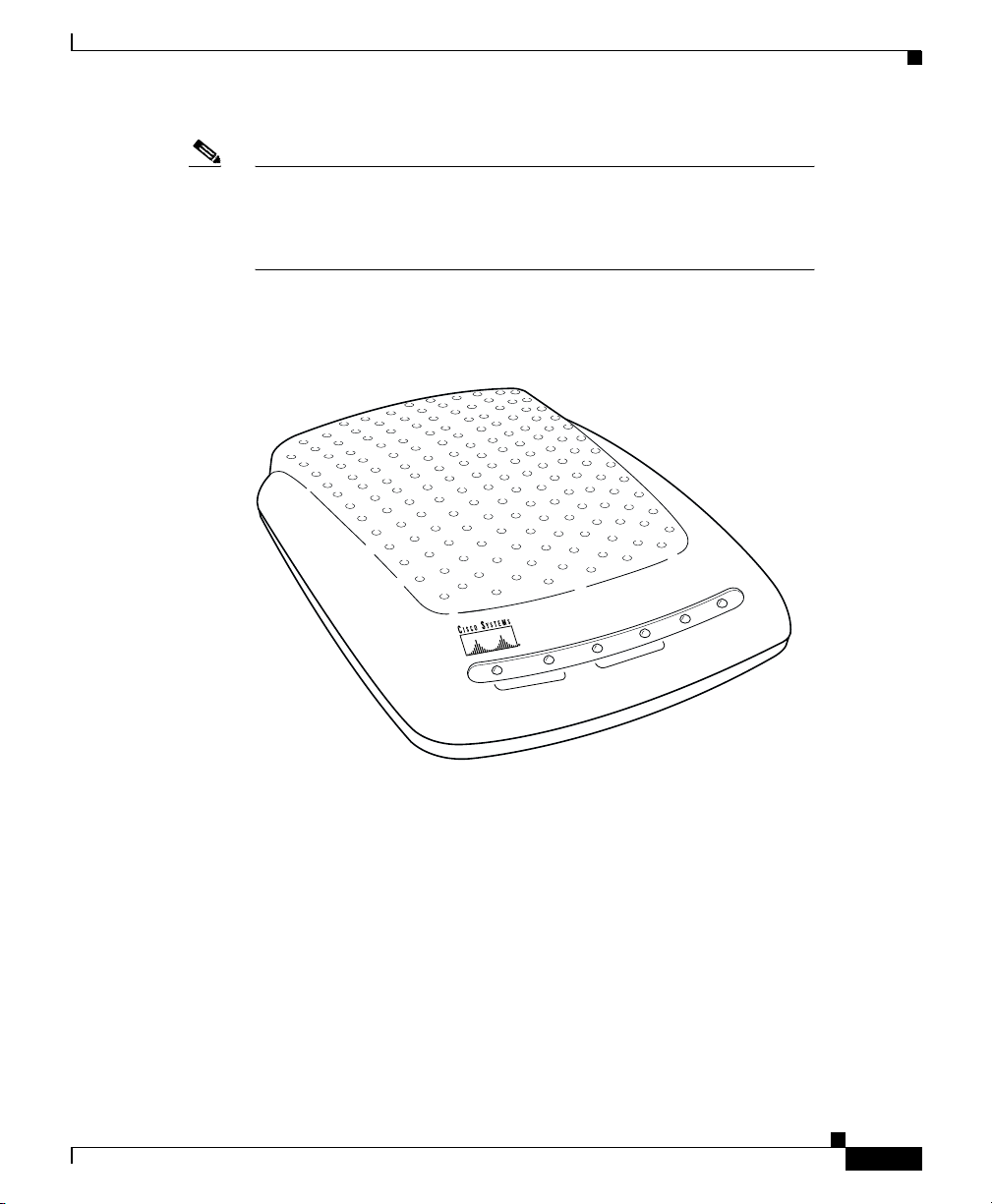
Figure 1-1 shows a front view of the generic Cisco 600 series CPEs.
Figure 1-1 Cisco 600 series CPEs
Cisco 6xx
POWER
ALARM
LNK
ACT
LNK
ACT
WAN
LAN
35266
System Features
Hardware Features
Table 1-2 summarizes the hardware features of the Cisco 600 series CPEs.
78-11190-01
Cisco 600 Series Installation and Operation Guide
1-3
Page 28

Product Description
Chapter 1 Overview of the Cisco 600 Series
Table 1-2 Cisco 600 Series CPE Hardware Features
Feature 627 633 673 675 675e 676 677 678
1
DMT Issue 1
-based ADSL
!
physical layer
DMT Issue 22 (T1.413),
!!!
G.Lite (G.992.2)-based
ADSL physical layer
SDSL3 interface with 2B1Q
!!
line code
CAP ADSL4 interface
G.DMT-based ADSL
!!
!! !
physical layer
Serial interface with Frame
!
Relay encapsulation
ATM25 interface
ATM cell delineation
!
!!!!!!!!
adherent to ITU-T I.432
Supports ATM
!!!!!!!!
Forum-compliant PVCs)
Autonegotiating 10BaseT or
!!!!!!
100BaseTX Ethernet
interface, compliant with
IEEE 802.3 and 802.3u Fast
Ethernet
Status LEDs indicating
!!!!!!!!
ATM25/Ethernet/Serial and
ADSL/SDSL activity
1-4
1
Discrete Multi-Tone Issue 1
2
Discrete Multi-Tone Issue 2
3
Symmetrical digital subscriber line
4
Asymmetric digital subscriber line
Cisco 600 Series Installation and Operation Guide
78-11190-01
Page 29

Chapter 1 Overview of the Cisco 600 Series
Software Features
Table 1-3 summarizes the software standards supported by the Cisco 600 series
CPEs.
Standards Compliance
Table 1-3 Standards Compliance
Standard 627 633 673 675 675e 676 677 678
DMT (ANSI T1.413) Issue 1
DMT (ANSI T1.413) Issue 2
Point-to-Point Protocol
(RFC 1661)
(PPP)
Multiprotocol Encapsulation
over ATM Adaptation Layer 5
RFC 1483)
(
ATM Forum UNI Version 3.1
PVC
IEEE 802.3 and 802.3u
10BaseT and 100BaseTX
Physical Layer Specification
IEEE 802.1d Transparent
Learning Bridging
PPP Bridging Control
Protocol (BCP)
Splitterless ADSL
Transceivers G.992.2
Product Description
!
!!!
!!!!!!
!!!!!!!!
!!!!!!!!
!!!!!!
!!!!!!!
!!!!!!
(RFC 1638)
!!!
1
American National Standards Institute
Routing Support (Cisco 67x)
•
78-11190-01
Internet Protocol
User Datagram Protocol
–
(RFC 791)
(RFC 768)
Cisco 600 Series Installation and Operation Guide
1-5
Page 30

Product Description
Chapter 1 Overview of the Cisco 600 Series
Bridging Support
Management
Internet Control Message Protocol
–
Ethernet Address Resolution Protocol
–
RIP version 1 updating of routing tables
–
Static routing
•
•
Remote Authentication Dial-In User Service (RADIUS) Security and
Accounting
Dynamic Host Configuration Protocol (DHCP) client and server
•
Network Address Translation (NAT)
•
Transparent learning bridge:
•
–
–
Management channel support for remote configuration/management
•
(RFC 2058, RFC 2059)
Multiprotocol Encapsulation over ATM Adaptation Layer 5 (
PPP (Bridging Control Protocol)
(RFC 792)
(RFC 826)
RFC 1483)
(RFC 1638)
Table 1-4 summarizes the management methods supported by the Cisco 600 series
CPEs.
1-6
Table 1-4 Management Methods
Management method 627 633 673 675 675e 676 677 678
HTML browser interface
Command-line interface
Telnet support
1
TFTP
SNMP2 MIB3 support
Multilevel password protection
Enables different logins
through serial management
port
Cisco 600 Series Installation and Operation Guide
!!!!!!!
!!!!!!!!
!!!!!!!!
!!!!!!!!
!!!!!
!!!!!!!!
!
78-11190-01
Page 31

Chapter 1 Overview of the Cisco 600 Series
1
Trivial File Transfer Protocol
2
Simple Network Management Protocol
3
Management Information Base
System Memory
The Cisco 600 series CPEs are equipped with 4 MB of DRAM.
Environmental Constraints
The Cisco 600 series CPEs operate in an ambient temperature environment of 32°
to 104
of – 40
F (0° to 40°C) and may be stored in an ambient temperature environment
°
to 185°F (– 40°to 85°C).
°
Network Management and Security Applications
Note
Electrical equipment generates heat. Ambient air temperature might
not be adequate to cool equipment to acceptable operating
temperatures without adequate circulation. Ensure that the room in
which you operate the CPE has adequate air circulation.
Be careful not to block the air vents on the CPE.
Network Management and Security Applications
The Cisco 627 and Cisco 633 support the following network system management
applications:
Telnet server described in “Using Telnet” section on page 3-6.
•
TFTP server described in “Using a Trivial File Transfer Protocol Server”
•
section on page 3-10.
The general applications supported by the Cisco 673, Cisco 675, Cisco 675e,
Cisco 676, Cisco 677, and Cisco 678 are:
DHCP client and server
•
NAT
•
78-11190-01
Cisco 600 Series Installation and Operation Guide
1-7
Page 32

Network Management and Security Applications
Ping
•
RADIUS
•
RIP
•
SNMP
•
SYSLOG client
•
Telnet server
•
TFTP server and client
•
Traceroute
•
Web server (HTTP server)
•
Chapter 1 Overview of the Cisco 600 Series
For more information on each of these applications, see the “
Applications” section on page 5-18.
Configure
1-8
Cisco 600 Series Installation and Operation Guide
78-11190-01
Page 33

Installation Procedures
This chapter provides information about installing the Cisco 600 series CPE
devices.
Installation Checklist
Table 2-1 lists the tasks to be completed when installing the Cisco 600 series CPE.
Table 2-1 Installation Checklist
Installation Procedures Page Number
Unpack the Shipping Carton
Set Up the Hardware Environment:
CHAPTER
2-2
2
78-11190-01
Connect the Management Port to the PC’s COM Port
•
Configure the PC’s COM Port
•
Possible Configurations
•
Connect Cables to the CPE
•
Power On the CPE
•
Cisco 600 Series Installation and Operation Guide
2-4
2-5
2-5
2-13
2-18
2-1
Page 34

Unpack the Shipping Carton
Unpack the Shipping Carton
Check the shipping carton carefully to ensure that the contents include the items
you ordered. You can identify the Cisco 600 series CPE by the product name on
the top of the unit at the end with the LEDs.
The contents of your carton might vary depending on your service provider.
Tables 2-2 and 2-3 show a list of the standard contents of a Cisco 600 series CPE
shipment.
Table 2-2 Standard Shipment Contents
Contents Description
Cisco 600 series CPE Cisco DSL CPE for home/office use.
Quick Start for the Cisco 6xx
Table 2-3 Standard Cables Shipped
Chapter 2 Installation Procedures
Quick start information for the
specific Cisco 600 series CPE model.
2-2
Cable 627 633 673 675 675e 676 677 678
Power supply—Wo r ldw ide AC
power adapter
ADSL/SDSL cable—RJ-11
telephone cable (14 ft)
ATM25 cable—Category 5
cable (6 ft)
Ethernet cable—Yel lo w
Ethernet category 5 “no-hub”
twisted pair crossover cable (6
ft)
SERIAL cable
(Blue)—12-in-1 Smart Serial
connector
If any items you ordered were not delivered, contact Cisco.
Cisco 600 Series Installation and Operation Guide
!!!!!!!!
!!!!!!!!
!
!!!!!!
!
78-11190-01
Page 35

Chapter 2 Installation Procedures
Hardware Requirements
The following hardware is necessary to configure the Cisco 600 series CPE:
PC with a standard terminal emulation program or a dumb terminal, with a
•
DB-9 COM port.
Hardware Requirements
Note
Management cable (RJ-45-to-DB-9) like the one in Figure 2-1 to connect the
•
CPE to the PC or dumb terminal you will use to configure it. You can order
one from Cisco or provide your own. See Appendix A, “Connectors”
information on connector pin assignments.
Figure 2-1 Management Cable
If only a DB-25 serial port is available on the computer,
a DB-9-male-to-DB-25-female adapter is also needed to
connect the management cable to the computer.
18429
for
Set Up the Hardware Environment
This section describes how to connect the Cisco 600 series CPE.
Cisco 600 Series Installation and Operation Guide
78-11190-01
2-3
Page 36

Set Up the Hardware Environment
Chapter 2 Installation Procedures
Note
Electrical equipment generates heat. Ambient air temperature might
not be adequate to cool equipment to acceptable operating
temperatures without adequate circulation. Ensure that the room in
which you operate the CPE has adequate air circulation.
Be careful not to block the air vents on the CPE.
Connect the Management Port to the PC’s COM Port
Step 1
Step 2
Connect the RJ-45 connector on the management cable to the MGMT port on the
CPE.
Connect the other end of the management cable to the computer’s COM port. If
your computer is equipped only with a DB-25 serial port, you need a
DB-9-male-to-DB-25-female adapter.
Figure 2-2 Cisco 600 series CPE Management Port Cabling
Cisco 6xx
2-4
PWR
Cisco 600 Series Installation and Operation Guide
WALLMGMT
110
35377
78-11190-01
Page 37

Chapter 2 Installation Procedures
Configure the PC’s COM Port
For the best access to the CBOS, use your terminal emulation program (such as
HyperTerminal in Windows) to set your COM protocol to the following settings:
Baud rate: 38400 bps recommended (standard 9600 bps possible)
•
Data bits: 8
•
Parity: None
•
Stop bits: 1
•
Flow control: None
•
Possible Configurations
This section shows you different ways of connecting your Cisco 600 series CPE
to your telephone and computer equipment, depending on whether or not your
telephone equipment is connected to a POTS splitter.
Table 2-4 shows the configurations that will work with each Cisco 600 series CPE
model.
Set Up the Hardware Environment
Table 2-4 Network Configurations
Configuration 627 633 673 675 675e 676 677 678
POTS Splitter
EZ-DSL (Splitterless)
Back-to-back
(bridging mode only)
!!!!!!!!
! !!!!!
!!
Back-to-Back Cabling (Cisco 633 and Cisco 673 only)
You can connect two Cisco 633s or Cisco 673s in a “back-to-back” configuration.
This allows one CPE to terminate the traffic of a second CPE without central
office (CO) equipment. This configuration can be used as a low-cost solution for
communicating between two locations at a distance greater than Ethernet’s
Cisco 600 Series Installation and Operation Guide
78-11190-01
2-5
Page 38

Set Up the Hardware Environment
100-meter range. The two locations must be directly connected, for example,
through some internally owned telephone system wiring in a campus-type
environment.
Chapter 2 Installation Procedures
Step 1
At the first location, connect one end of the SDSL cable into the WALL port on
one of the Cisco 633 or Cisco 673 units. Connect the other end of the SDSL cable
into the wall jack.
Step 2
At the second location, connect one end of the second SDSL cable into the WALL
port of the second Cisco 633 or Cisco 673 unit. Connect the other end of the
second SDSL cable into the wall jack.
Step 3
Configure the CPE that you want to terminate traffic to operate in CO mode and
the other to operate in CPE mode. See the “Attention Back-to-Back Connection
Users” section on page 4-5 for more information.
Note
Back-to-back configuration works in bridging mode only.
POTS Splitter Configuration (Required for the Cisco 627)
A POTS splitter separates data signals from voice signals on your telephone line.
The POTS splitter works by running a separate data line from the voice line, so
that the CPE has a dedicated cable for data transmission. Figure 2-3, Figure 2-4,
and Figure 2-5 show telephone equipment connected to a POTS splitter.
2-6
Cisco 600 Series Installation and Operation Guide
78-11190-01
Page 39

Chapter 2 Installation Procedures
Figure 2-3 Cisco 627 Connected through an Internal POTS Splitter
Voice
Set Up the Hardware Environment
Telephone
NID
POTS
Splitter
Data
Cisco 627
Cisco 3600
Cisco 4101
ATM25
Ethernet
35385
78-11190-01
Cisco 600 Series Installation and Operation Guide
2-7
Page 40

Set Up the Hardware Environment
Figure 2-4 Cisco 633 Connected through an Internal POTS Splitter
Voice
Cisco 2500, Cisco 2600,
or Cisco 3600
Cisco 4101
Telephone
POTS
Splitter
NID
Chapter 2 Installation Procedures
Data
Cisco 633
Serial
Ethernet
35450
2-8
Cisco 600 Series Installation and Operation Guide
78-11190-01
Page 41

Chapter 2 Installation Procedures
Figure 2-5 Cisco 67x Connected through an Internal POTS Splitter
Voice
POTS
Telephone
NID
Splitter
Set Up the Hardware Environment
Data
Cisco 67x
Note
The POTS splitter can also be installed adjacent to the telephone
network interface device (NID) on the outside of the house.
EZ-DSL™ (Splitterless) Configuration
Note
This configuration applies to the Cisco 627, Cisco 675, Cisco 675e,
Cisco 676, Cisco 677, and Cisco 678 only.
In the EZ-DSL configuration, your telephone equipment is not connected to a
POTS splitter. Without a POTS splitter and under certain circumstances, transient
noise from a telephone can interfere with the router’s operation, and the router can
cause noise on the telephone line. To prevent this from happening, small
Ethernet
Hub
35386
78-11190-01
Cisco 600 Series Installation and Operation Guide
2-9
Page 42

Set Up the Hardware Environment
microfilters must be connected to the telephone lines. If you implement an
EZ-DSL configuration, your installation landscape should look similar to
Figure 2-6, Figure 2-7, Figure 2-8, or Figure 2-9.
Figure 2-6 Cisco 627 Splitterless Configuration
Microfilter
Chapter 2 Installation Procedures
Ethernet
Telephone
NID
Microfilter
Data
Cisco 627
ATM25
Cisco 3600
Cisco 4101
35454
2-10
Cisco 600 Series Installation and Operation Guide
78-11190-01
Page 43

Chapter 2 Installation Procedures
Figure 2-7 Cisco 675 Splitterless Configuration
Microfilters
Set Up the Hardware Environment
Telephone
NID
Microfilter
Data
Cisco 675
Ethernet
Hub
35378
78-11190-01
Cisco 600 Series Installation and Operation Guide
2-11
Page 44

Set Up the Hardware Environment
Figure 2-8 Cisco 675e, Cisco 676, Cisco 677 Splitterless Configuration
Microfilters
Chapter 2 Installation Procedures
Telephone
NID
Microfilter
Data
Ethernet
Cisco 675e/Cisco 676/
Cisco 677
Hub
35379
2-12
Cisco 600 Series Installation and Operation Guide
78-11190-01
Page 45

Chapter 2 Installation Procedures
Figure 2-9 Cisco 678 Splitterless Configuration
Microfilters Microfilter
Set Up the Hardware Environment
Telephone
NID
Microfilter
Note
The microfilters do not work if connected improperly. For
connection instructions, see Appendix C, “EZ-DSL Microfilter
Specifications.”
Connect Cables to the CPE
This section describes how to connect cables to the CPE and to your telephone and
computer systems.
Data
Cisco 678
Ethernet
Hub
31519
78-11190-01
Cisco 600 Series Installation and Operation Guide
2-13
Page 46

Set Up the Hardware Environment
Cabling Diagrams
Chapter 2 Installation Procedures
Figures 2-10 through 2-13 show how to connect cables to the rear panels of
Cisco 600 series CPEs.
Figure 2-10 Rear Panel Cabling for the Cisco 633
PWR
Power
cable
SERIAL
12-in-1 Smart Serial
cable
MGMT
WALL
SDSL
cable
24591
2-14
Cisco 600 Series Installation and Operation Guide
78-11190-01
Page 47

Chapter 2 Installation Procedures
Figure 2-11 Rear Panel Cabling for the Cisco 627
Set Up the Hardware Environment
PWR
Power
cable
ATM25
ATM25
cable
MGMT
WALL
ADSL
cable
18432
78-11190-01
Cisco 600 Series Installation and Operation Guide
2-15
Page 48

Set Up the Hardware Environment
Figure 2-12 Rear Panel Cabling for the Cisco 673, Cisco 675e, Cisco 676, and
Chapter 2 Installation Procedures
Cisco 677
PWR
Power
cable
ENET
Ethernet
cable
MGMT
WALL
DSL
cable
28553
2-16
Cisco 600 Series Installation and Operation Guide
78-11190-01
Page 49

Chapter 2 Installation Procedures
Figure 2-13 Rear Panel Cabling for the Cisco 675 and Cisco 678
Set Up the Hardware Environment
Cabling Instructions
To connect the cables to the Cisco 600 series CPE:
Step 1
Step 2
Plug the power cable into the back of the unit.
Plug the network cable into the ATM25 port of the Cisco 627, or the ENET port
of the Cisco 67x.
PWR
Power
cable
ENET
Ethernet
cable
MGMT
WALL
ADSL
cable
PHONE
Phone
cable
24555
78-11190-01
For the Cisco 633, connect one end of the serial cable to the SERIAL port.
Connect the other end to your router.
Cisco 600 Series Installation and Operation Guide
2-17
Page 50

Power On the CPE
Chapter 2 Installation Procedures
For the Cisco 627, connect the other end of the network cable to your premises
router, for example, a Cisco 3600 series router.
For the Cisco 67x, if the customer premises has only a single Ethernet-equipped
computer, attach the Cisco 600 series CPE to the computer’s Ethernet adapter
with the crossover cable provided. Otherwise, connect the Cisco 600 series CPE
Ethernet port to an Ethernet hub via a straight-through cable (not provided).
Step 3
Connect the telephone cable to the WALL port. Connect the other end of the
telephone cable in the appropriate configuration as discussed in the “
Configurations” section on page 2-5.
Step 4
(Optional step for the Cisco 678) Plug the microfilter into the PHONE port. Then
plug the telephone into the microfilter.
Note
Never connect a telephone directly to the PHONE port of the
Cisco 678; this affects the CPE’s performance.
Step 5
(Optional step for the Cisco 675) Plug the telephone into the PHONE port. The
telephone can be connected directly to the PHONE port of the Cisco 675 because
it uses a built-in microfilter.
Power On the CPE
Step 1
Connect power to the Cisco 600 series CPE by plugging the power supply into an
appropriate electrical outlet.
Possible
2-18
Note
Use only the Cisco-approved power supply that shipped
with the CPE as your power supply.
Note
Cisco recommends that you unplug your CPE when you are
not using it.
Cisco 600 Series Installation and Operation Guide
78-11190-01
Page 51

Chapter 2 Installation Procedures
Next Step
Step 2
Step 3
Note
Next Step
When you have powered up the Cisco 600 series CPE, check that the Power LED
is ON.
If the Power LED is not lit, immediately remove the barrel power connector from
the Cisco 600 series CPE. Refer to Chapter 6
information.
To power down the Cisco 600 series CPE, unplug the power supply
cable from the Cisco 600 series CPE rear panel PWR connector.
Now that you have installed and powered on your Cisco 600 series CPE, you must
configure it.
To configure the Cisco 627, see Chapter 3
Cisco 627.”
To configure the Cisco 633, see Chapter 4, “Configuration Procedures for the
Cisco 633.”
To configure the Cisco 673, Cisco 675, Cisco 67e, Cisco 676, Cisco 677 or
Cisco 678, see Chapter 5
Devices.”
, “Configuration Procedures for the Cisco 67x CPE
, “Troubleshooting,” for
, “Configuration Procedures for the
Warnings and Cautions
Warning
78-11190-01
To prevent dangerous overloading of the power circuit, read the
label on the bottom of the Cisco 600 series CPE that indicates
maximum power load ratings. Failure to follow these rating
guidelines could result in a dangerous situation.
Cisco 600 Series Installation and Operation Guide
2-19
Page 52

Warnings and Cautions
Chapter 2 Installation Procedures
Warning
Warning
Warning
Warning
Caution
Warning
Do not use this product near water; for example, near a bath tub,
wash bowl, kitchen sink or laundry tub, in a wet basement, or near
a swimming pool.
Never install telephone wiring during an electrical storm.
Never install telephone jacks in wet locations unless the jack is
specifically designed for wet locations.
Never touch uninsulated telephone wires or terminals unless the
telephone line has been disconnected at the network interface.
Use caution when installing or modifying telephone lines.
Avoid using a telephone (other than a cordless type) during an
electrical storm. There may be a remote risk of electric shock from
lightning.
2-20
Warning
Do not use a telephone to report a gas leak in the vicinity of the
leak.
Cisco 600 Series Installation and Operation Guide
78-11190-01
Page 53

Configuration Procedures for the
Cisco 627
Introduction
This chapter provides information about configuring your Cisco 627. Your unit is
preconfigured for full operation. However, you might need to configure the
Cisco 627 for management virtual connections (VCs).
Configuration Checklist
Table 3-1 identifies the configuration procedures you might need.
CHAPTER
3
78-11190-01
Table 3-1 Checklist for Configuration
Configuration Procedures Page Number
Log On to the Cisco Broadband Operating System
Configure Management Virtual Connections
Update the CBOS Prompt
Set Passwords
Save Configuration Changes
Evaluate System Activity and Performance
Retrieve Statistics
Cisco 600 Series Installation and Operation Guide
3-2
3-3
3-18
3-19
3-19
3-20
3-20
3-1
Page 54

Chapter 3 Configuration Procedures for the Cisco 627
Log On to the Cisco Broadband Operating System
Log On to the Cisco Broadband Operating System
After connecting all cables to the Cisco 627 and powering it on, start the terminal
emulation program and press the
System (CBOS) welcome screen appears. When you see the welcome screen, you
can log on to CBOS.
Hello!
Expanding CBOS image...
CBOS v2.3.5.012 - Release Software
Password:
Determine the CBOS Version
key until the Cisco Broadband Operating
Enter
After you log on to CBOS, you can use the
the CBOS version of the Cisco 627:
cbos# show version
Operation Modes
CBOS also has two modes of operation:
exec
execution) privileges to a user.
To write changes to NVRAM, you must work in
mode:
Step 1
Step 2
At the command line, enter:
cbos> enable
Enter the enable password when CBOS prompts you:
Password:
mode when you log on. The
show version
and
exec
mode grants read-only (command
exec
enable
command to determine
. The CBOS defaults to
enable
mode. To invoke
enable
3-2
Cisco 600 Series Installation and Operation Guide
78-11190-01
Page 55

Chapter 3 Configuration Procedures for the Cisco 627
Configure Management Virtual Connections
Note
If you have not set any passwords, press the
key when the
Enter
system prompts you for a password.
Configure Management Virtual Connections
Your system comes preconfigured for full and immediate network operation.
However, you might need to manage your Cisco 627 directly over the network. To
do this, you must establish and set management virtual connections (VCs).
Note
Note
You must be in the
Each interface is expressed as atmx, where x is either 0 or 1. The atm0 interface
is reserved for ATM25. The atm1 interface is used for the ADSL remote interface.
The valid range for VPI is 0 to 255. 0 to 65535 is the valid range for VCI
addresses.
The Cisco 627 is configured with atm0 using VPI/VCI 0/34 by
default. The atm0 interface is used for management. Cisco
recommends that you do not change VPI/VCI values for atm0.
mode to perform these procedures.
enable
Changing VPI Settings
Step 1
Step 2
Step 3
78-11190-01
To set the VPI number to 2, enter:
cbos# set interface atm1 vpi 2
To begin using this connection with the new settings, enter:
cbos# set interface atm1 enable
To verify your setting:
cbos# show interface atm1
Cisco 600 Series Installation and Operation Guide
3-3
Page 56

Configure Management Virtual Connections
A display similar to the following will appear on your screen:
atm1 RFC1483 Ethernet HWaddr 00:E0:D0:01:19:7F
IP address 10.0.1.1 Mask 255.255.255.0
MTU 1500 Metric 0
RX packets 0 errors 0
TX packets 0 errors 0
Port is currently enabled with link status
VCI 34 VPI 2
Severely Errored Frame Count:0
Data rate 6944 Kbps down; 480 Kbps up
Line capacity 7456 Kbps down; 480 Kbps up
SNR Margin 8 dB; previous 8 dB
Attenuation 13.0 dB; previous 13.0 dB
Status:
Last Self-Test Result:Not Available
Modem Microcode: 0x1119be0d
Configured:
Trellis Coding: Enabled
Echo Cancellation: Disabled
FDQ Adaptation: Enabled
Rate Adaptation: Normal
Overhead Framing: Mode-3
Bit-Swapping: Disabled
ATM Payload Scrambling: Disabled
PGA-Cutback: 0 dB
Actual:
FEC Redundancy Bytes:
Interl. Path: downstream: 16, upstream 0
Fast Path: downstream: 0, upstream 0
Interleaver Depth: downstream: 0, upstream 0
Trellis Coding: Not-Used
Echo Cancellation: Not-Used
FDQ Adaptation: In-Use
Overhead Framing: Mode-0 (910 compatible)
Bit-Swapping: Not-Used
Last Line Fault: NONE
ATM Statistics:
Interleaved-Path Counters:
HEC errors: 0
LOCD events: 0
Fast-Path Counters:
HEC errors: 0
LOCD events: 0
DSL Statistics:
Superframes: 956
Corrected Superframes: 0 (+INF)
Uncorrected Superframes: 0
LOCD Retrains 0
Chapter 3 Configuration Procedures for the Cisco 627
3-4
Cisco 600 Series Installation and Operation Guide
78-11190-01
Page 57

Chapter 3 Configuration Procedures for the Cisco 627
LOS Retrains: 0
LOF/RFI Retrains: 0
ES Events: 0
Time Trained (h:m:s) 0:00:16
Trained...
Configure Management Virtual Connections
Step 4
Step 5
Note
To save the new WAN port configuration, enter:
cbos# write
To exit CBOS, enter:
cbos# quit
To close an ATM management connection, enter:
disable
steps substituting
Changing VCI Settings
Step 1
To set the VCI number to 32, enter:
cbos# set interface atm0 vci 32
To verify your setting:
cbos# show interface atm0
A display similar to the following will appear on your screen:
atm0 RFC1483 Ethernet Hwaddr 00:E0:D0:01:19:7F
IP address 192.168.1.100 Mask 255.255.255.0
MTU 1500 Metric 0
RX packets 0 errors 0
TX packets 0 errors 0
Port is currently disabled with no link status
VCI 32 VPI 0
set interface atm
. To set the ATM25 management VPI, repeat the previous
atm0
for
atm1
.
x
78-11190-01
Step 2
To begin using this connection with the new settings, enter:
cbos# set interface atm0 enable
Cisco 600 Series Installation and Operation Guide
3-5
Page 58

Using Telnet
Chapter 3 Configuration Procedures for the Cisco 627
Step 3
Step 4
Note
To save the new WAN port configuration, enter:
cbos# write
To exit CBOS, enter:
cbos# quit
To close an ATM management connection, enter:
disable
substituting
Using Telnet
Telnet provides a command-line interface for remote login connections between
machines on many networks, including the Internet. To establish a Telnet
connection to the CPE, Telnet must be enabled in CBOS.
Caution
Before closing a Telnet connection, always enter
cbos#
set interface atmx
. To set the ADSL ATM VCI, repeat the previous steps
atm1
for
atm0
.
or
exit
quit
prompt.
at the
Connecting from a Windows NT or Windows 95 Machine
3-6
Step 1
Step 2
Step 3
Step 4
Step 5
Click the
Select the
When the Run box appears, enter
Click the OK button. The Connect menu appears.
Select the
List Box appears. (See Figure 3-1.)
Cisco 600 Series Installation and Operation Guide
button.
Start
option.
Run...
Remote System...
telnet
in the space provided.
option from the Connect menu. The Remote System
78-11190-01
Page 59

Chapter 3 Configuration Procedures for the Cisco 627
Figure 3-1 Remote System List Box
Using Telnet
Step 6
Enter the atm0 IP address of your modem in the
Connect
initiated, information similar to the following displays:
User Access Verification
Password:
Note
Step 7
Provide the logon and password information. After the system authenticates your
password, you have access to the CBOS.
Note
You can log on to the CPE using no password by pressing the
key at the password prompt. Refer to the “Set Passwords
page 3-19 for more information about how to set and change
passwords.
Notice to Windows Users
Windows’ Telnet client does not support NVT (Network Virtual Terminal) or any
extra form of option negotiation. However, if you are going to use the Windows
Telnet client, complete the following steps to set your terminal settings.
Host Name
box and click
. The system then initiates a connection session. When connection is
Press the
key several times to establish a connection.
Enter
Enter
” section on
78-11190-01
Cisco 600 Series Installation and Operation Guide
3-7
Page 60

Using Telnet
Chapter 3 Configuration Procedures for the Cisco 627
Step 1
When the Telnet window appears, go to the
Preferences
Figure 3-2 Telnet Preferences
. (See Figure 3-2.)
Ter mi nal
drop-down menu, and click
3-8
Step 2
Set the terminal settings on the Terminal Preferences menu to the values shown in
Figure 3-3.
Figure 3-3 Terminal Preferences
Cisco 600 Series Installation and Operation Guide
78-11190-01
Page 61

Chapter 3 Configuration Procedures for the Cisco 627
Notice to Linux Users
When you run Linux without installing the Term/Termcap database, the message
BAD ADDRESS
displays during a connection attempt. Use the original Linux
installation disks to install the Term/Termcap database.
Connecting from a UNIX Machine
The following procedure describes how to log on to your modem from a UNIX
system:
Using Telnet
Step 1
Enter the following at your prompt:
telnet IP address of atm0
After you have connected, information similar to the following appears on your
display:
Cisco Broadband Operating System
CBOS (tm) 2.3.5.012 - Release Software
Copyright (c) 1986-1999 by cisco Systems, Inc.
cbos>
Step 2
Provide the login and password information. After the system authenticates your
password, you have access to CBOS.
How to Keep Telnet from Timing Out During Your Session
Telnet sessions time out after a period of inactivity. Enter the following commands
to keep the Telnet client from timing out.
cbos# set telnet timeout off
cbos# write
The
set telnet timeout off
must explicitly set it for every session.
setting is not saved in NVRAM after a reboot. You
78-11190-01
Cisco 600 Series Installation and Operation Guide
3-9
Page 62

Chapter 3 Configuration Procedures for the Cisco 627
Using a Trivial File Transfer Protocol Server
Using a Trivial File Transfer Protocol Server
The Trivial File Transfer Protocol (TFTP) enables you to transfer files to and from
your modem. Your system runs a
TFTP client software, to transfer files to and from the system. The TFTP client is
enabled and disabled from the CBOS or the Web Management Interface.
daemon that enables remote users who have
tftp
Caution
For security reasons, Cisco recommends that you disable the TFTP
application, except when uploading or downloading a file.
Software Updates
Use the TFTP utility to transfer a new software image from Cisco to your system,
where the filename equals nsrouter.c627.x.ima, where
Versions of CBOS 2.3 or higher use the filename format c627.x.bin, where x is the
release number.
Archives
Use the TFTP utility to back up a copy of your configuration file before changing
it,
so you can easily recover the old file if necessary. The naming conventions for the
configuration file are:
When using the
•
nscfg.cfg.
When using the
•
a standard text editor can view and edit.
option of the
put
option of the
get
Using TFTP from a UNIX Machine
is the release number.
x
command, you must name the file
tftp
command, name the file any name that
tftp
3-10
For information on the UNIX TFTP client, access the online manual on your
UNIX system. At the command-line prompt, enter:
man tftp
Cisco 600 Series Installation and Operation Guide
78-11190-01
Page 63

Chapter 3 Configuration Procedures for the Cisco 627
The manual page for TFTP appears. The TFTP UNIX man page contains all the
information you need to establish and invoke a remote TFTP session.
Using TFTP from a Windows NT Machine
Before attempting to use TFTP, make sure of the following:
On the Cisco 627, TFTP is enabled and the IP address of the ATMx port is the
•
same IP address used in Step 2 of the following procedure.
The ATMx port is enabled, and the VCI/VPI is set correctly on it.
•
The remote host computer must be configured for RFC 1483 Logical Link
•
Control (LLC)/Subnetwork Access Protocol (SNAP) encapsulation if the PC
is directly connected to the CPE through the atm0 interface, or verify the IP
connectivity between the PC and the CPE.
To us e TF T P:
Using a Trivial File Transfer Protocol Server
78-11190-01
Step 1
Step 2
Start a DOS session and verify connectivity from the PC to the CPE. Enter:
C:>ping
IP address
Enter one of the following commands:
C:>tftp -i IP address put nsrouter software image filename
C:>tftp -i IP address put system configuration config filename
C:>tftp -i IP address put DSP firmware file name
where
IP address
is the IP address of the ATMx port.
Where necessary, implement the following options:
- Sets the transfer mode to binary mode.
-i
- Uploads a file to that IP address.
put
Note
The CPE might take up to 2 minutes to upgrade the
firmware. Wait until the management console reappears
before rebooting the CPE.
Cisco 600 Series Installation and Operation Guide
3-11
Page 64

Upgrade Software through Serial Download
Chapter 3 Configuration Procedures for the Cisco 627
Step 3
Be sure that you reboot the device to activate the new image. When you log back
on to your system after the reboot, use the following command to verify the
version of the firmware that is active:
cbos# show version
Notice to Windows 95 Users
Windows 95 does not have a TFTP client. If you want to utilize TFTP on a
Windows 95 system, you must install a TFTP client from a third-party vendor on
your system. One way to locate a TFTP client is to use an Internet search engine
to locate a vendor who sells a TFTP client. Some TFTP clients are provided as
share or freeware on the Internet. By request, Cisco will provide a TFTP client.
Upgrade Software through Serial Download
You can upgrade software on your CPE using the serial interface:
Step 1
Enter the following settings through a serial console connected to your system:
38.4 Kbaud
No parity
8 data bits
1 stop bit
No flow control
3-12
Step 2
Step 3
Step 4
To turn debug monitor on, enter:
debug monitor on
To save your changes, enter:
write
To reboot the device, enter:
reboot
After the modem reboots, press
Cisco 600 Series Installation and Operation Guide
twice. The prompt should change to =>.
Enter
78-11190-01
Page 65

Chapter 3 Configuration Procedures for the Cisco 627
Configure Line Coding
Step 5
Step 6
Step 7
Step 8
Step 9
Step 10
Step 11
To erase sector 0, enter:
es 0
Repeat this step for sectors 1 through 5.
To start serial download, enter:
df 10008000
Use a terminal emulation application, such as Hyperterminal, to start an Xmodem
download of a new Cisco 67x image.
When the download is complete, the following message appears:
Transferred xxxxxxxx bytes
Record the number of bytes transferred.
To program the area of memory to Flash, enter:
pb 10008000 fef00000
where
xxxxxxxx
is the value recorded in Step 6.
xxxxxxxx
To turn debug monitor off, enter:
m0
To reboot, enter:
rb
Configure Line Coding
The Cisco 627 allows you to choose transmission protocols to match your network
configuration by changing the CPE’s configuration file and operating system. You
will use the TFTP to transfer files to and from the CPE. This section describes
procedures to configure the Cisco 627 for G.Lite and G.DMT protocols.
Note
78-11190-01
Changes to your CPE must be coordinated with the central office
equipment.
Cisco 600 Series Installation and Operation Guide
3-13
Page 66

Configure Line Coding
Configure for DMT2
Chapter 3 Configuration Procedures for the Cisco 627
Step 1
Step 2
Step 3
Step 4
Verify the connection from the router to the location where the correct software
image is stored. This location is provided by your service provider. Typically,
you use the
command for this step.
ping
Enable TFTP by entering:
cbos#set tftp enabled
TFTP is enabled
Set the remote address for the TFTP host computer by entering:
cbos # tftp remote ip address
This command tells the CPE to accept TFTP transfers from a specific IP address.
An example remote IP address would be
192.168.35.4.
This address is an example
only; do not use it to configure the router.
Note
If you do not have the CPE address, consult your network
administrator.
For more information about TFTP, see “
Using a Trivial File
Transfer Protocol Server” section on page 3-10.
To start the file transfer from a PC, start a DOS session and enter the following
command:
C:>tftp –i CPE IP address put image_filename
3-14
To start the file transfer from a UNIX machine, enter the following commands:
root@staten-</6xx>tftp
tftp> mode binary
tftp> put CPE IP address:image_filename
Sent 922294 bytes in 54.9 seconds
Cisco 600 Series Installation and Operation Guide
78-11190-01
Page 67

Chapter 3 Configuration Procedures for the Cisco 627
Where necessary, implement the following values:
Configure Line Coding
-i
get
put
Sets the transfer mode to binary mode
Downloads a file to a specified IP address
Uploads a file onto that IP address
Substitute the filename for the software image update. See the latest
Notes for the Cisco Broadband Operating System
appropriate filenames to use.
Caution
Do not turn off the power to the router until after the file transfer is
completed.
Step 5
Be sure to reboot the CPE to activate the new image. When you log back in to the
CPE after the reboot, use the
firmware that is active. Note the DMT firmware version.
Sample Output of Configuration Session for DMT2
cbos#set tftp enabled
TFTP is enabled
show version
Release
available on CCO for the
command to verify the version of the
78-11190-01
cbos#tftp image TFTP_server_IP_address image_filename
Starting download...
Downloading in progress...... done.
Saving image...........done.
Please reboot the CPE for the new downl
cbos#reboot
Hello!
C6xx self-update code: Release 2.3.5.012
NOTE: Do not power off router until update is finished!
Decompressing router...
Erasing FLASH......
Programming...
Decompressing monitor...
Erasing FLASH.........
Programming...
Cisco 600 Series Installation and Operation Guide
3-15
Page 68

Configure Line Coding
Finished. Rebooting...
Hello!
Expanding CBOS image...
CBOS v2.3.5.012 - Release Software
User Access Verification
Password:
cbos>enable
Password:
cbos#show version
Cisco Broadband Operating System
CBOS (tm) 627 Software (C627-I-M), Version v2.3.0.053, RELEASE
SOFTWARE
Copyright (c) 1986-1999 by cisco Systems, Inc.
Compiled Feb 13 2000 17:36:16
Monitor build 111 (Feb 13 2000 17:37:07)
Configure for G.DMT
Chapter 3 Configuration Procedures for the Cisco 627
3-16
Before the CPE can be configured for G.DMT, the
the latest
Release Notes for the Cisco Broadband Operating Sytsem
appropriate filenames to use. The central office hardware must be correctly
configured to accept a G.DMT service user.
Step 1
Step 2
Enter the following command:
cbos# set interface atm1 standard g.992.1
Be sure to retrain the CPE to activate the new line code. When the CPE is
retrained, use the
show interface atm1
is active. Note that the standard configuration for the
Note
Changes made to the running configuration must be written
to NVRAM for changes to be seen on reboot.
Cisco 600 Series Installation and Operation Guide
image must be loaded. See
.full
for the
command to verify the G.DMT standard
image is DMT2.
.full
78-11190-01
Page 69

Chapter 3 Configuration Procedures for the Cisco 627
Sample Output of Configuration Session for G.DMT
cbos#set interface atm1 standard
SET INTERFACE WANx STANDARD requires one of the following arguments
T1.413
G.dmt (G992.1)
cbos#set interface atm1 standard g.992.1
Note: Change will take effect on next retrain.
cbos#show interface atm1
atm1 ADSL Physical Port
Line Trained
Actual Configuration:
Overhead Framing: 3
Trellis Coding: Disabled
Standard Compliance: g.992.1
Downstream Data Rate: 8032 Kbps
Upstream Data Rate: 864 Kbps
Interleave S Downstream: 1
Interleave D Downstream: 64
Interleave R Downstream: 2
Interleave S Upstream: 4
Interleave D Upstream: 8
Interleave R Upstream: 16
Modem Microcode: G96
DSP version: 0
Operating State: Showtime/Data Mode
Configured:
Echo Cancellation: Disabled
Overhead Framing: 3
Coding Gain: Auto
TX Power Attenuation: 0dB
Trellis Coding: Enabled
Bit Swapping: Disabled
Standard Compliance: Multimode
Remote Standard Compliance:g.992.1
Tx Start Bin: 0x6
Tx End Bin: 0x1f
Data Interface: Utopia L1
Status:
Local SNR Margin: 3.5dB
Local Coding Gain: 0.0dB
Local Transmit Power: 12.5dB
Local Attenuation: 28.5dB
Remote Attenuation: 18.5dB
Local Counters:
Interleaved RS Corrected Bytes: 0
Configure Line Coding
78-11190-01
Cisco 600 Series Installation and Operation Guide
3-17
Page 70

Update the CBOS Prompt
Interleaved Symbols with CRC Errors: 2
No Cell Delineation Interleaved: 0
Out of Cell Delineation Interleaved: 0
Header Error Check Counter Interleaved:0
Count of Severely Errored Frames: 0
Count of Loss of Signal Frames: 0
Remote Counters:
Interleaved RS Corrected Bytes: 0
Interleaved Symbols with CRC Errors: 0
No Cell Delineation Interleaved: 0
Header Error Check Counter Interleaved:0
Count of Severely Errored Frames: 0
Count of Loss of Signal Frames: 0
Update the CBOS Prompt
Chapter 3 Configuration Procedures for the Cisco 627
Step 1
Step 2
Step 3
Step 4
The default Cisco 627 system prompt is
. The command prompt is limited
cbos#
to 8 characters. You can change this prompt to a unique subscriber identifier as
shown in the following example.
Log on to the CBOS using either the serial or Telnet interfaces. Refer to the
“
Using Telnet” section on page 3-6 for more information on how to use Telnet to
log on to the CBOS.
To change the default prompt to 4412883 as the subscriber identifier, enter:
cbos# set prompt 4412883
4412883#
To save your changes, enter:
4412883# write
To exit the CBOS, enter:
4412883# quit
3-18
Cisco 600 Series Installation and Operation Guide
78-11190-01
Page 71

Chapter 3 Configuration Procedures for the Cisco 627
Set Passwords
After you have configured your system, you should pick new passwords for both
the
functionality of a system administrator for the CPE. Examples of good and bad
passwords are:
•
•
and
enable
exec modes
Good Password—77ta99y (Do not use the sample password.)
Bad Passwords—Passwords such as your name; or your street address, or
home telephone number are too predictable.
. Keep in mind that the
mode provides all the
enable
Set Passwords
Use the
set password
command to change both the enable and exec passwords as
in the following:
Step 1
To change the password enter:
cbos# set password mode new password
Example:
set password enable 33Low44PassMe
set password exec 44High55Pass
Step 2
Step 3
To save your changes, enter:
cbos# write
To exit CBOS, enter:
cbos# quit
Save Configuration Changes
Use the
to the NVRAM configuration file:
cpe627# write
command to save any changes you have made during provisioning
write
78-11190-01
Caution
If you do not use the
command after changes, all the changes
write
you made during your current session will be lost when you reboot
the Cisco 627.
Cisco 600 Series Installation and Operation Guide
3-19
Page 72

Chapter 3 Configuration Procedures for the Cisco 627
Evaluate System Activity and Performance
Evaluate System Activity and Performance
Table 3-2 describes the LEDs and their status.
Table 3-2 Status LEDs
LED Label Full Name Description
WAN-LNK WAN Link When this light is ON, it indicates that a link has been
established on the WAN port. The WAN-LNK light blinks
steadily during ADSL line training activities. When the light
is solid, the system is connected and trained.
WAN-ACT WAN Activity When this light blinks, it indicates that the WAN port is
transmitting or receiving data.
LAN-LNK ATM25 LAN Link When this light is ON, it indicates that a link has been
established on the ATM-25 port.
Note
LAN-ACT ATM25 LAN Activity When this light blinks, it indicates activity on the ATM-25
port.
PWR Power Light When this light is Green, the system is ON and working
correctly.
ALARM Alarm Light When the light is Red, the system is ON but indicates a
problem that needs to be resolved.
For some ATM-25 routers or NICs, this light may not
be on till data is sent to the modem.
Retrieve Statistics
The
and received and activity information about general applications.
Cisco 600 Series Installation and Operation Guide
3-20
command shows information about the number of packets transmitted
stats
78-11190-01
Page 73

Chapter 3 Configuration Procedures for the Cisco 627
To retrieve statistics:
Interpret Statistics
Step 1
Step 2
Step 3
To see a list of variables, enter:
cbos# stats
To display specific statistics, enter:
cbos# stats variable from list
To exit the CBOS, enter:
cbos# quit
Interpret Statistics
Use the
regarding ADSL performance. These statistics are:
stats atm0
CRC Errors—Number of CRC errors. CRC errors might occur when the ATM
•
traffic rate is faster than the ADSL rate, causing ATM cells to be dropped.
This corrupts the AAL5 logical packets. CRC errors might also be an
indication of excessive noise on the DSL line.
Errored Seconds—Number of Superframe CRC errors. If this field is
•
incremented, the user data path is encountering uncorrected errors.
Rx’ed Blocks—Number of blocks received by the unit. A block is 250
•
milliseconds. This statistic is reset whenever the modem trains.
and
show interface atm1
commands to retrieve key statistics
78-11190-01
Tx’ed Blocks—Number of blocks transmitted by the unit. A block is 250
•
milliseconds. This statistic is reset whenever the modem trains.
Corrected/Uncorrected Blocks—The modem can correct a block containing
•
errors. If the block correction fails, the block is counted as an uncorrected
block and discarded.
Attenuation—Difference in decibels (dB) between the power level received
•
at the near end versus the power level transmitted from the far end. The
attenuation range is 0 to 63 dB in 1 db increments. Attenuation is calculated
every 10 seconds.
Cisco 600 Series Installation and Operation Guide
3-21
Page 74

Interpret Statistics
Chapter 3 Configuration Procedures for the Cisco 627
Signal-to-Noise (SNR) Margin—Amount of increased received signal noise
•
(in decibels) relative to the signal noise power level the unit is designed to
tolerate without disconnecting from the network. The SNR Margin range is
-64.0 to +63 dB in 1 dB increments. SNR Margin is calculated every
10 seconds. The previous value is moved to the Previous SNR Margin field.
Previous SNR Margin—Last SNR Margin measurement, which occurs
•
approximately every 10 seconds.
Operation, Administration, Maintenance (OAM) Loopback Cells—The Cisco
•
627 supports the Operation, Administration, and Maintenance (OAM) F5
loopback cell to verify end-to-end ATM network connectivity. The OAM-F5
loopback cell is generated by a network-side system. The cell is injected into
a specific virtual circuit along with the normal user traffic flow. The cell is
carried unmodified by each intermediate ATM switching node until it arrives
at the circuit's other endpoint such as the Cisco 627. The receiving endpoint
modifies the cell payload to indicate that the cell has been looped back and
transmits this new cell back into the ATM circuit. It is relayed by each
intermediate node until it arrives at the original transmitting endpoint. The
receipt of this cell indicates a valid end-to-end connection between the two
endpoints over the intervening ATM network.
3-22
Cisco 600 Series Installation and Operation Guide
78-11190-01
Page 75

Introduction
CHAPTER
4
Configuration Procedures for the
Cisco 633
This chapter provides instructions for configuring the Cisco 633 SDSL modem.
Configuration procedures vary depending on how your Cisco 633 is configured
when shipped. You must be in
procedures.
mode to perform these configuration
enable
Note
Checklist
78-11190-01
Cisco recommends that only one command-line application at a time
be used to configure the Cisco 633. For example, Telnet and the
serial management interface should not be used simultaneously.
Table 4-1 Checklist for Configuration
Configuration Procedures Page Number
Log on to Cisco Broadband Operating System
Configure Interworking
Configure the Cisco 633 for Remote Management
Cisco 600 Series Installation and Operation Guide
4-2
4-3
4-4
4-1
Page 76

Chapter 4 Configuration Procedures for the Cisco 633
Log on to Cisco Broadband Operating System
Table 4-1 Checklist for Configuration (continued)
Configuration Procedures Page Number
Configuring External Routers 4-6
Upgrade Software through Serial Download
Update the CBOS Prompt
Set Passwords
Save Configuration Changes
4-6
4-8
4-8
4-9
Log on to Cisco Broadband Operating System
After connecting all the cables to the Cisco 633 and powering it on, start the
terminal emulation program and press the
appears. When you see the welcome screen, you can log on to CBOS.
Hello!
Expanding CBOS image...
CBOS v2.3.5.012
key until the CBOS login screen
Enter
User Access Verification
Password:
Note
If you have not set any passwords for the Cisco 633, press the
key when the system prompts you for a password to enter CBOS.
Determine the CBOS Version
After you log on to CBOS and before proceeding any further with your
configuration process, check the version of CBOS to verify that the version
number and date reflect the most recent firmware update:
cbos> show version
Cisco 600 Series Installation and Operation Guide
4-2
Enter
78-11190-01
Page 77

Chapter 4 Configuration Procedures for the Cisco 633
If the CBOS version is earlier than 2.2.0, get the latest version from Cisco. See
the Trivial File Transfer Protocol (
Operating System User Guide
Cisco 633 firmware. You can also update the CBOS version through the
management port also.
Operation Modes
Configure Interworking
) command in the
tftp
Cisco Broadband
for more information on how to update the
Step 1
Step 2
Note
CBOS implements two operational modes:
mode when you log in. The
exec
mode grants program execution (read-only)
exec
exec
and
. CBOS defaults to
enable
privileges to a user. To read or write changes to nonvolatile random-access
memory (NVRAM), you must work in
At the
cbos> enable
mode command-line prompt, enter:
exec
mode. To invoke the
enable
enable
Enter a password when CBOS prompts you:
cbos> enable
Password:
If you have not set any passwords for the Cisco 633, press the
Enter
key when the system prompts you for a password to enter CBOS. If
you have not preset a password, you can still log on to CBOS.
You are now in
cbos#
mode. The system prompt appears:
enable
mode:
Configure Interworking
To translate from Frame Relay (FR) to ATM, you must first configure an IWF data
path.
78-11190-01
Cisco 600 Series Installation and Operation Guide
4-3
Page 78

Configure the Cisco 633 for Remote Management
Chapter 4 Configuration Procedures for the Cisco 633
Step 1
Step 2
Step 3
Step 4
Step 5
Close the virtual WAN port for which you are creating an IWF:
set int wan0-1 close
Configure a Data Link Connection ID (DLCI) on the FR (serial) network:
set int serial0-1 dlci 17
Note
Enter a DLCI range between 16 and 1007.
Repeat steps 1 and 2 to create multiple IWF data paths.
Write the changes to Non-Volatile Read Only Memory (NVRAM):
write
Reboot the Cisco 633:
reboot
Configure the Cisco 633 for Remote Management
Remote management allows you to configure the Cisco 633.
4-4
Note
The WAN0-0 and SER0-0 interfaces are reserved for remote
management.
Step 1
Step 2
Close the WAN0-0 port:
set int wan0-0 close
Decide which side of the network you are on, either the FR network (SER0-0) or
the ATM (WAN0-0) network. The following steps show configuration for the
ATM network.
Step 3
Cisco 600 Series Installation and Operation Guide
Configure an IP address for the WAN0-0 interface:
set int wan0-0 ip 10.0.1.0
78-11190-01
Page 79

Chapter 4 Configuration Procedures for the Cisco 633
Configure the Cisco 633 for Remote Management
Step 4
Step 5
Step 6
Step 7
Step 8
Step 9
Configure a netmask address for the WAN0-0 interface:
set int wan0-0 mask 255.255.255.0
Add a static IP route to and from the remote network. This allows data to pass
between your Cisco 633 and the remote network.
set route add ip x.x.x.x gw wan0-0
where
Note
is the static IP route to and from the remote network.
x.x.x.x
You must add a static route or you will not be able to pass
data.
To Telnet to the Cisco 633, enable the Telnet application:
set telnet enabled
To use the Trivial File Transfer Protocol (TFTP) to transfer files to and from the
Cisco 633, enable the TFTP application:
set tftp enabled
To save your changes, enter:
write
To reboot the CPE, enter:
reboot
The Cisco 633 is now configured for remote management. Now the FR router (for
example, a Cisco 1600) needs to be configured to pass management data. See the
following section for more information.
Attention Back-to-Back Connection Users
The back-to-back configuration between two Cisco 633 units allows one
Cisco 633 to act as CO equipment and terminate traffic initiated by another
Cisco 633.
78-11190-01
Cisco 600 Series Installation and Operation Guide
4-5
Page 80

Configuring External Routers
Chapter 4 Configuration Procedures for the Cisco 633
Step 1
Step 2
Step 3
Step 4
Cable the two Cisco 633s. See the “Back-to-Back Cabling (Cisco 633 and
Cisco 673 only)” section on page 2-5 for cabling information.
Set one Cisco 633 to central office (CO) mode, so that it terminates the traffic that
the Cisco 633 in customer premises equipment (CPE) mode initiates.
Note
To set the Cisco 633 to CO mode:
set int wan0 mode co
Set up an IWF data path between the Cisco 633s. See the “Configure
Interworking” section on page 4-3 for more information.
Verify that both Cisco 633s are in either RFC 1483 bridging or RFC 1483 routing
mode only, not PPP (Point-to-Point Protocol) routing or bridging mode. See the
sections below for either bridging or routing procedures.
The Cisco 633 ships with a default setting of CPE mode.
Configuring External Routers
Please consult the user documentation for your router to connect the Cisco 633 to
routers on the FR and ATM networks. The Cisco 633 can pass traffic that uses the
following protocols:
RFC 1483 bridging
•
PPP bridging
•
Upgrade Software through Serial Download
You can upgrade software on your CPE using the serial interface:
Note
Cisco 600 Series Installation and Operation Guide
4-6
Changes to your CPE must be coordinated with the central office
equipment.
78-11190-01
Page 81

Chapter 4 Configuration Procedures for the Cisco 633
Upgrade Software through Serial Download
Step 1
Step 2
Step 3
Step 4
Step 5
Step 6
Enter the following settings through a serial console connected to your system:
38.4 Kbaud
No parity
8 data bits
1 stop bit
No flow control
To turn debug monitor on, enter:
debug monitor on
To save your changes, enter:
write
To reboot the device, enter:
reboot
After the modem reboots, press Enter twice. The prompt should change to =>.
To erase sector 0, enter:
es 0
Repeat this step for sectors 1 through 5.
To start serial download, enter:
df 10008000
78-11190-01
Step 7
Step 8
Step 9
Step 10
Use a terminal emulation application, such as Hyperterminal, to start an Xmodem
download of a new Cisco 67x image.
When the download is complete, the following message appears:
Transferred xxxxxxxx bytes
Record the number of bytes transferred.
To program the area of memory to Flash, enter:
pb 10008000 fef00000 xxxxxxxx
where
xxxxxxxx
is the value recorded in Step 6.
To turn debug monitor off, enter:
m0
Cisco 600 Series Installation and Operation Guide
4-7
Page 82

Update the CBOS Prompt
Chapter 4 Configuration Procedures for the Cisco 633
Step 11
To reboot, enter:
rb
Update the CBOS Prompt
The default Cisco 633 system prompt is
to 8 characters. You can change this prompt to a unique subscriber identifier as
shown in the following example.
Step 1
Step 2
Step 3
Step 4
Log on to CBOS using either the serial or Telnet interfaces.
To change the default prompt to 4412883 as the subscriber identifier, enter:
cbos# set prompt 4412883
4412883#
To save your changes, enter:
4412883# write
To exit CBOS, enter:
4412883# quit
. The command prompt is limited
cbos>
Set Passwords
After you have configured your system, you should pick new passwords for both
the
enable
functionality of a system administrator for the CPE. Examples of good and bad
passwords are:
Good Password—77ta99y (Do not use the sample password.)
•
Bad Passwords—Passwords such as your name; or your street address, or
•
home telephone number are too predictable.
Cisco 600 Series Installation and Operation Guide
4-8
and
exec modes
. Keep in mind that the
mode provides all the
enable
78-11190-01
Page 83

Chapter 4 Configuration Procedures for the Cisco 633
Save Configuration Changes
Use the
set password
command to change both the enable and exec passwords as
in the following:
Step 1
Step 2
Step 3
To change the password enter:
cbos# set password mode new password
Example:
set password enable 33Low44PassMe
To save your changes, enter:
cbos# write
To exit the CBOS, enter:
cbos# quit
Save Configuration Changes
Use the
to the NVRAM configuration file:
cpe627# write
command to save any changes you have made during provisioning
write
78-11190-01
Caution
If you do not use the
command after changes, all the changes
write
you made during your current session will be lost when you reboot
the Cisco 633.
Cisco 600 Series Installation and Operation Guide
4-9
Page 84

Save Configuration Changes
Chapter 4 Configuration Procedures for the Cisco 633
4-10
Cisco 600 Series Installation and Operation Guide
78-11190-01
Page 85

Introduction
CHAPTER
5
Configuration Procedures for the Cisco 67x CPE Devices
This chapter provides information about configuring the Cisco 67x CPE devices.
This information applies to the Cisco 673, Cisco 675, Cisco 675e, Cisco 676,
Cisco 677, and Cisco 678.
Note
Cisco recommends that only one command-line application at a time
be used to configure the Cisco 67x. For example, Telnet and the
serial management interface should not be used simultaneously.
Also, please note that all configuration procedures are performed in
the
enable
mode.
Configuration Checklist
Table 5-1 Checklist for Router Configuration
Configuration Procedures Page Number
Log On to the Cisco Broadband Operating System
Determine the CBOS Version
Select a Connection Mode
78-11190-01
5-3
5-3
5-5
Cisco 600 Series Installation and Operation Guide
5-1
Page 86

Configuration Checklist
Chapter 5 Configuration Procedures for the Cisco 67x CPE Devices
Table 5-1 Checklist for Router Configuration (continued)
Configuration Procedures Page Number
Bridging Mode Procedures or Routing Mode Procedures 5-5 or 5-8
Configure the Ethernet Port (eth0)
Configure the WAN Ports and ATM Virtual Connections
Create Routing Tables
Enable IP Filtering
Configure Applications
:
5-11
5-12
5-16
5-17
5-18
DHCP Client
•
DHCP Server
•
NAT
•
RADIUS Client
•
SNMP
•
SYSLOG Client
•
Tel n e t
•
TFTP Server
•
Web S e r ver
•
Configure Timeout Values (Cisco 675, Cisco 678 in CAP
mode only)
Configure Line Coding (Cisco 677 and Cisco 678 only)
Upgrade Software through Serial Download
Configure Static NAT
Configure Multiple PCs Connected to the CPE
Update the CBOS Prompt
Set Passwords
Save Configuration Changes
Evaluate System Activity and Performance
Retrieve Statistics
5-18
5-19
5-20
5-20
5-22
5-23
5-24
5-27
5-30
5-30
5-31
5-42
5-43
5-44
5-46
5-47
5-48
5-48
5-49
5-2
Cisco 600 Series Installation and Operation Guide
78-11190-01
Page 87

Chapter 5 Configuration Procedures for the Cisco 67x CPE Devices
Log On to the Cisco Broadband Operating System
Log On to the Cisco Broadband Operating System
After connecting all the cables to the Cisco 67x and powering it on, start the
terminal emulation program and press the
appears. When you see the welcome screen, you can log on to CBOS.
Hello!
Expanding CBOS image...
CBOS v2.3.5.012 - Release Software
Password:
key until the CBOS login screen
Enter
Note
If you have not set any passwords for the Cisco 67x, press the
key when the system prompts you for a password to enter CBOS.
Determine the CBOS Version
After you log on to CBOS, you can use the
the CBOS version of the Cisco 67x:
cbos# show version
The output for Cisco 67x configured for CAP line coding is similar to the
following:
Cisco Broadband Operating System
CBOS (tm) 678 Software (C678-I-M), Version v2.3.5.012 - Release
Software
Copyright (c) 1986-1999 by cisco Systems, Inc.
Compiled Jan 10 2000 03:54:07
CAP firmware version C.19
NVRAM image at 0x10357fe0
show version
Enter
command to determine
78-11190-01
Cisco 600 Series Installation and Operation Guide
5-3
Page 88

Log On to the Cisco Broadband Operating System
The output for Cisco 678 configured for DMT Issue 2, G.Lite line coding is
similar to the following:
Cisco Broadband Operating System
CBOS (tm) 678 Software (C678-I-M), Version v2.3.5.012 - Release
Software
Copyright (c) 1986-1999 by cisco Systems, Inc.
Compiled Jan 5 2000 00:07:36
DMT firmware version 210
NVRAM image at 0x1034d930
*** RFC1483 Bridging Mode Enabled ***
Chapter 5 Configuration Procedures for the Cisco 67x CPE Devices
Note
The
either CAP or DMT, for which the Cisco 67x is configured. If you
have a Cisco 677 or Cisco 678 and need to upgrade to a different line
coding method, follow the procedure in the “
(Cisco 677 and Cisco 678 only)” section on page 5-31 before
proceeding with configuration.
Operation Modes
The CBOS implements two operational modes:
to
exec
(read-only) privileges to a user. To read or write changes to nonvolatile
random-access memory (NVRAM), you must work in
enable
Step 1
Step 2
Type enable at the exec mode command line:
cbos> enable
Enter a password when CBOS prompts you:
cbos> enable
Password:password
show version
command above displays the line coding method,
mode when you log in. The
mode:
Configure Line Coding
and
exec
mode grants program execution
exec
enable
mode. To invoke
enable
. CBOS defaults
5-4
Cisco 600 Series Installation and Operation Guide
78-11190-01
Page 89

Chapter 5 Configuration Procedures for the Cisco 67x CPE Devices
Select a Connection Mode
Note
If you have not set any passwords for the Cisco 67x, press the
key when the system prompts you for a password to enter CBOS. If
you have not preset a password, you can still log on to the CBOS.
You must have an
Cisco 67x.
You are now in
cbos#
enable
password set in order to Telnet into the
exec
mode. The system prompt appears:
Select a Connection Mode
The CBOS supports two kinds of connection modes: bridging and routing.
Routing mode has two options: PPP routing (default) and RFC 1483 routing.
Note
Routing and bridging cannot be used simultaneously.
Bridging Mode Procedures
When the Cisco 67x operates in bridge mode, it behaves like a wire connecting a
local PC directly to a service provider’s network. Bridge data is encapsulated
using the RFC 1483 or PPP (BCP) protocol to enable data transport. Because
bridges operate at the Media Access Control (MAC) layer only, applications
requiring IP communication, such as Telnet, TFTP, RADIUS, Syslog, Ping, and
the web interface, are not available unless a management VC is configured.
Cisco currently supports a learning bridge mode. The virtual path
identifier/virtual channel identifier (VPI/VCI) configuration of the Cisco 67x is
unaffected by the operational mode (bridging versus routing) of the device.
Enter
78-11190-01
Cisco also provides two methods of configuring and managing the bridged
Cisco 67x, through in-band bridging management or through a separate
management VC. The two methods cannot be used simultaneously. If a separate
management VC is used, the Cisco 67x can only be managed remotely through
wan0-1 and not from the local network.
Cisco 600 Series Installation and Operation Guide
5-5
Page 90

Bridging Mode Procedures
With RFC 1483 management enabled, you can manage the router using Telnet.
The following commands are accessible through the managed bridge:
The following procedure shows how to set up the Cisco 67x for in-band bridging
management.
•
•
•
Chapter 5 Configuration Procedures for the Cisco 67x CPE Devices
ping
telnet
tftp
Note
Step 1
Step 2
Step 3
Step 4
Step 5
Step 6
You must be in
mode and perform the procedure in the
enable
sequence shown.
To enable RFC 1483 bridging, enter:
set bridging rfc1483 enabled
To save your changes, enter:
write
To reboot the device, enter:
reboot
To enable in-band management of the bridge, enter:
set bridging management enabled
set int eth0 address ip address
The IP address of the Ethernet port should be an IP address on the same network
as that of the “far-end” station.
To save your changes, enter:
write
To enable your changes, reboot the router:
reboot
5-6
Cisco 600 Series Installation and Operation Guide
78-11190-01
Page 91

Chapter 5 Configuration Procedures for the Cisco 67x CPE Devices
To manage the bridged Cisco 67x using a separate management VC:
Bridging Mode Procedures
Step 1
Step 2
Step 3
Step 4
Step 5
To disable in-band bridging management, enter:
set bridging management disabled
To enable bridging PVC, enter:
set bridging PVC enabled
To save your changes, enter:
write
To reboot the device, enter:
reboot
After rebooting, the Cisco 67x will have two PVCs enabled. Wan0-0 is used
strictly for bridged traffic, while wan0-1 is used strictly for management traffic.
Wan0-1 will be using RFC 1483 routing.
Set an IP address on the Ethernet port that is on the same network as the far-end
station out the wan0-1 interface:
set int eth0 address ip address
For more information on using the
set bridging
Broadband Operating System User Guide
The rules that govern the
Bridging and routing do not operate simultaneously on the Cisco 67x ADSL
•
bridge
command are:
command, see the
.
Cisco
router.
Only one bridging mode is allowed at any one time (that is, RFC 1483 or
•
PPP/BCP, not both).
78-11190-01
The following commands do not work while in bridge mode:
•
–
set route
RIP-related commands (
–
Filter-related commands (
–
Web interface (only allowed if management is enabled)
–
(and setting static routes)
and
set
Cisco 600 Series Installation and Operation Guide
set
show
and
show
)
)
5-7
Page 92

Chapter 5 Configuration Procedures for the Cisco 67x CPE Devices
Routing Mode Procedures
RADIUS
–
Syslog
–
NAT
–
If you choose bridging as your connection mode, see also the following sections:
“Configure the WAN Ports and ATM Virtual Connections” section on
•
page 5-12
“Configure Applications” section on page 5-18 through “Evaluate System
•
Activity and Performance” section on page 5-48
Routing Mode Procedures
The Cisco 67x CPEs support two types of routing: PPP routing and RFC 1483
routing.
PPP Routing
Three Cisco 67x applications compose the PPP routing feature: DHCP server, and
Network Address Translation (NAT). With these applications enabled, you can
use the Cisco 67x without following the procedures described in this chapter such
as the “
WAN Ports and ATM Virtual Connections” section on page 5-12. See the
following section to enable PPP routing.
Enabling PPP Routing
For each of the applications, the
is enabled. Complete the following steps to enable the PPP routing feature for the
Cisco 67x. You must be in the
Step 1
Cisco 600 Series Installation and Operation Guide
5-8
Enable the DHCP server:
set dhcp server enabled
Bridging Mode Procedures” section on page 5-5 or the “Configure the
application
show
mode to do this procedure.
enable
command reports if the feature
78-11190-01
Page 93

Chapter 5 Configuration Procedures for the Cisco 67x CPE Devices
Routing Mode Procedures
Step 2
Step 3
Step 4
Step 5
Step 6
Step 7
To check whether this feature is enabled, enter:
show dhcp server pool 0
Enable NAT:
set nat enabled
Reboot the Cisco 67x:
reboot
To check whether NAT is enabled, enter:
show nat
Write the changes to NVRAM:
write
Reboot the Cisco 67x:
reboot
When the Cisco 67x reboots, PPP routing is enabled.
Disabling PPP Routing
78-11190-01
Step 1
Step 2
Step 3
Complete the following steps to disable the PPP routing feature for the Cisco 67x.
You must be in the
enable
mode.
Disable the DHCP server:
set dhcp server disabled
Disable NAT:
set nat disabled
Write the changes to NVRAM:
write
Cisco 600 Series Installation and Operation Guide
5-9
Page 94

Routing Mode Procedures
Chapter 5 Configuration Procedures for the Cisco 67x CPE Devices
Step 4
Note
Reboot the Cisco 67x:
reboot
After you disable the PPP routing feature, you must manually
configure the Cisco 67x.
Changing PPP Routing
These commands change the components of PPP routing:
•
•
•
•
•
•
For a complete description of each of these commands, see the
Operating System User Guide
set dhcp server pool
set dhcp client -interface
set nat entry add
set nat entry delete
set nat timeout
set nat outside -ip
Cisco Broadband
.
RFC 1483 Routing
If you disable PPP routing, see the following steps for RFC 1483 routing: from
the “
“
Evaluate System Activity and Performance” section on page 5-48.
Cisco 600 Series Installation and Operation Guide
5-10
Configure the Ethernet Port (eth0)” section on page 5-11 through the
78-11190-01
Page 95

Chapter 5 Configuration Procedures for the Cisco 67x CPE Devices
Configure the Ethernet Port (eth0)
To configure the Ethernet port, you must assign an IP address and netmask to the
port. Complete the following steps to configure your IP address and your netmask.
When setting the IP address of a particular interface, the netmask is set
automatically unless it is explicitly specified. Substitute your own IP addresses
for the ones shown in steps 2 through 4.
Configure the Ethernet Port (eth0)
Step 1
Step 2
Step 3
Step 4
Step 5
You must be in the
enabled
Log on to the CBOS (
Note
When changing the Cisco 67x IP configuration, use the
mode to do this procedure:
) using the serial connection.
cbos#
serial management connection to ensure you maintain your
session connection to CBOS.
To set the IP address (and your netmask), follow this example of a sample
command:
set interface eth0 address 192.168.34.9
The IP address becomes 192.168.34.9 and the netmask becomes 255.255.255.0 by
default. If you wish to explicitly set the netmask, enter:
set interface eth0 mask 255.255.255.248
To set the destination IP address for the WAN port, enter:
set interface wan0-0 dest 192.168.34.10
To save your changes, enter:
write
To allow the system to come up with these new settings, reboot the Cisco 67x:
reboot
78-11190-01
Step 6
Log back on to the CBOS to continue.
For more detailed information on the
set interface
Broadband Operating System User Guide
Cisco 600 Series Installation and Operation Guide
command, see the
Cisco
.
5-11
Page 96

Chapter 5 Configuration Procedures for the Cisco 67x CPE Devices
Configure the WAN Ports and ATM Virtual Connections
Configure the WAN Ports and ATM Virtual
Connections
The Cisco 67x has two types of WAN ports: physical (wan0) and logical
(wan0-x). The physical WAN port connects the Cisco 67x to the wide area
network. The logical WAN port or ports allow you to create virtual WAN
connections for plural destinations. To configure logical WAN ports, you must
provision ATM virtual connections. The instructions for each are provided in this
section.
The Cisco 67x automatically trains up to the ideal line speed. By default, the
Cisco 67x is provisioned with the following rates:
Encoding Downstream/Upstream Rate (Mbps)
DMT 8.032/.864
CAP 7.168/1.088
G.Lite 1.536/.512
5-12
The maximum operative rate is determined by the central office ADSL equipment,
line length and line conditions.
On the Cisco 67x, the WAN0 port is always ready to send and receive network
traffic.You need to define an ATM virtual connection (VC), which might differ
from the default, when communicating across an ATM network. There are two
types of ATM connections:
Virtual paths, identified by virtual path identifiers (VPI)
•
Virtual circuit, identified by the combination of a VPI and a virtual circuit
•
identifier (VCI).
Because the Cisco 67x connects to the Cisco 6xxx series, the subscriber side
VPI/VCI settings are not seen by the ATM network. All subscriber side VCs use
VPI 1 and VCI 1 by default.
Cisco 67x comes preconfigured with one VC already established. Each VC is
expressed as WAN0-x, where x is a number between 0 and 3.
Cisco 600 Series Installation and Operation Guide
78-11190-01
Page 97

Chapter 5 Configuration Procedures for the Cisco 67x CPE Devices
To set the maximum number of VCs, enter:
cbos# set interface wan0 maxvcs n
where n is between 1 and 8.
Table 5-2 shows the valid ranges for the VPI and VCI addresses.
Table 5-2 VPI/VCI Address Ranges
Maximum VCs VPI Range VCI Range
10-3 0-63
20-3 0-63
40-3 0-63
80-3 0-63
Configure the WAN Ports and ATM Virtual Connections
Note
In CBOS version 2.3 or earlier, the VPI count is 1 to 4. In later
versions, the VPI count is 1 to 8.
Changing VPI Settings
Step 1
Step 2
78-11190-01
To make sure the wan0-0 connection remains closed during configuration, enter:
set interface wan0-0 disable
To set the VPI number to 2, enter:
set interface wan0-0 vpi 2
Note
If you try to enter the command
set interface wan0-1
on a
connection that is already open, the system prompts you to
close that connection before you change the VPI setting.
Close the connection by entering
.
close
Cisco 600 Series Installation and Operation Guide
set interface wan0-1
5-13
Page 98

Configure the WAN Ports and ATM Virtual Connections
Chapter 5 Configuration Procedures for the Cisco 67x CPE Devices
Step 3
Step 4
Step 5
Step 6
Step 7
To enable the wan0-0 connection, enter:
set interface wan0-0 enable
To begin using this connection with the new settings, enter:
set interface wan0-0 open
Repeat steps 2 through 4 for every VPI assignment you want to make.
To save the new WAN port configuration, enter:
write
To exit CBOS, enter:
quit
Changing VCI Settings
Step 1
Step 2
To make sure the wan0-0 connection remains closed during configuration, enter:
set interface wan0-0 disable
To set the VCI number to 4, enter:
set interface wan0-0 vci 4
5-14
Note
If you try to enter the command
connection that is already open, the system prompts you to
close that connection before you change the VCI setting. To
do this, enter the command
Step 3
Step 4
Step 5
Cisco 600 Series Installation and Operation Guide
To enable the wan0-0 connection, enter:
set interface wan0-0 enable
To begin using this connection with the new settings, enter:
set interface wan0-0 open
Repeat steps 2 through 4 for every VCI assignment you want to make.
set interface wan0-0
set interface wan0-0 close.
on a
78-11190-01
Page 99

Chapter 5 Configuration Procedures for the Cisco 67x CPE Devices
Set ScalaRate for wan0-x
Step 6
Step 7
To save the new WAN port configuration, enter:
write
To exit CBOS, enter:
quit
For more information on configuring VPI/VCI address mapping, see the
Broadband Operating System User Guide
Set ScalaRate for wan0-x
ScalaRate is a technology developed by Cisco that allows dynamic allocation of
bandwidth within an ATM-based ADSL connection. This bandwidth allocation is
specified and controlled by the end-point devices without affecting the
provisioning or status of the underlying ATM transport VC. Bandwidth within the
ADSL connection is allocated on a VC basis and provides flexibility in rate
structures and deployment models for service providers and network
administrators.
The key features of ScalaRate are:
Applicable to individual logical WAN ports (wan0-x).
•
Sets maximum upstream rate per VC in the CPE, and maximum downstream
•
rate per subscriber in the central office equipment.
Cisco
.
78-11190-01
Step 1
Can be set in increments of 64 Kbps.
•
Rounds down to the nearest 64 Kbps increment. For example, if you set the
•
rate to 68 Kbps, the setting will be rounded down to 64 Kbps.
Can be set for less than or equal to the maximum ADSL trained rate.
•
To set the wan0-x to ScalaRate:
To close the wan0-x port, enter:
set interface wan0-x close
where x is the port you want to close.
Cisco 600 Series Installation and Operation Guide
5-15
Page 100

Create Routing Tables
Chapter 5 Configuration Procedures for the Cisco 67x CPE Devices
Step 2
Step 3
Step 4
Step 5
To set an upstream ScalaRate for a particular VC, enter:
cbos# set interface wan0-0 rate 512
To set an upstream ScalaRate to the maximum allowable rate, enter:
cbos# set interface wan0-0 rate auto
To save your changes, enter:
cbos# write
To exit the CBOS, enter:
cbos# quit
Create Routing Tables
In order to pass data through a network and onto the Internet or wide area network,
you might need to add the IP address(es) of gateway(s) to the routing table. Follow
the instructions below to build a routing table manually by adding or deleting
entries in the table.
Note
If your Cisco 67x was provisioned to run in bridging or PPP routing
mode, you must disable both before attempting to establish routing.
5-16
Step 1
To add a route and gateway to IP address 192.168.9.1, without specifying a
specific mask or metric, enter:
set route add ip 192.168.9.1 gw 192.168.10.250
Step 2
Step 3
Cisco 600 Series Installation and Operation Guide
To add a route and specify a netmask, gateway, or metric, enter:
set route add ip 192.168.10.0 mask 255.255.255.0
gw 192.168.245.228 metric 1
To set a default route, enter:
set route default 192.168.245.228
78-11190-01
 Loading...