

Page 1

Cisco 575 LRE CPE Hardware
Installation Guide
April 2001
Corporate Headquarters
Cisco Systems, Inc.
170 West Tasman Drive
San Jose, CA 95134-1706
USA
http://www.cisco.com
Tel: 408 526-4000
800 553-NETS (6387)
Fax: 408 526-4100
Customer Order Number: DOC-7811469=
Text Part Number: 78-11469-01
Page 2

THE SPECIFICATIONS AND INFORMATION REGARDING THE PRODUCTS IN THIS M ANUAL ARE SUBJECT TO CHANGE WITHOUT
NOTICE. ALL STATEMENTS, INFORMATION, AND RECOMMENDATIONS IN THIS MANUAL ARE BELIEVED TO BE A CCURATE BUT
ARE PRESENTED WITHOUT WARRANTY OF ANY KIND, EXPRES S OR IMPLIED. USERS MUST TAKE FULL RESPONSIBILITY FOR
THEIR APPLICATION OF ANY PRODUCTS.
THE SOFTWARELICENSE AND LIMITED WARRANTY FOR THE ACCOMPANYING PRODUCT ARE SET FORTHIN THE INFORMATION
PACKET THAT SH IPPED WITH THE PRODUCT AND ARE INCORPORATED HEREIN BY THIS REFERENCE. IF YOU ARE UNABLE TO
LOCATE THE S OFTWARE LICENSE OR LIMI TED WARRANTY, CONTACT YOUR CISCO REPRESENTATIVE FOR A COP Y.
The following information is f or FCC c ompli ance of Cl ass A d evices: This eq uip ment has been tested and foun d to compl y with th e limits for a Class
A digi tal device, pursuant to part 15 of the FC C rules. These limits are designed to provide reasonable protection against harmful interfer ence when
the equipment is operated in a co mmerci al environment. This e quipmen t generates, uses, and can radiate radio-frequency energy and , if no t installed
and used in accordance with the instruction manual, may cau se harm ful interferen ce to radio com munications. Operation of this equipment in a
residential area is likely to cause harmful interference, in wh ich case users will be required to correct the interference at their own exp ense.
The following information is for FCC compl iance of Class B devices: The equipment described in this m anual gener ates and may r adiate
radio-frequency energy. If it is not installed in accordance with Cisco’s installation instruct ions, it may cause interference with radio and television
reception. This equipment has been tested and found to co mply with the limits for a Class B digital device in accordance wi th the specif ications in
part 15 of the FCC rules. These specifications are designed to provide reasonable protection against such interference in a residential installation.
However, there is n o guara ntee that in terference wil l not occur in a particular installation.
Modifying the equipment wit hou t C isco’s written authori zatio n may res ult in the equipment no longer com ply ing wi th FC C re quir em ents f or Cl ass
A or Class B digital devices. In that event, your right to use the equipm ent ma y be limited by FCC regul atio ns, an d you may be required to cor r ect
any interference to radio or tel evisi on com mu nicat ions at yo ur o wn expen s e.
You ca n deter mi ne whet her your eq uip ment is cau sing in ter ference by turning it off. If the interference stops, it was probably caused by t he C isco
equipment or one of its peripheral dev ices. If t he equi pment causes i nterferenc e to rad io or televi sion recept ion , try to correct the interference by
using one or more of th e fol low ing m easures :
• Turn the television or radi o anten na until the interferen c e sto ps.
• Move the equipment to on e si de or t he oth er of t he tel evis ion or radio.
• Move the equipment farther away from the t elevi sion or radio.
• Plug the equipment into an outlet that is on a different circuit from the televi sion or radio. (That is, make certain the equipment and the television
or radio are on circuits cont ro lled b y different ci rcuit br eakers o r fus es.)
Modifications to this p rod uct no t auth orized by Cisco Systems, Inc. co uld v oid the FCC approval and neg ate you r a uth ority t o operate the product.
The Cisco impl ementatio n of TCP header compression is an adaptation of a program developed by the University o f California, Berkel ey (UCB) as
part of UCB’s pu blic domain version of the UNIX operating system. All rights res erv ed. Copyright © 1981, Regents of the Uni versi ty of California.
NOTWITHSTANDING ANY OTHER WARRANTY HE REIN, AL L DOCUM ENT FILES AND SOFTWARE OF THESE SUPPLIERS ARE
PROVIDED “AS IS” WITH ALL FAULTS. CISCO A ND THE ABO VE-NAMED SUPP LIERS DISC LAIM ALL WARRANTIES, E XPRESSED
OR IMPLIED, INCLUDING, WITHOUT LIMITATION, THOSE OF MERCHANTABILITY, FITN ESS FOR A PARTICULAR PURPOSE AND
NONINFRINGEMENT OR ARISING FROM A COURSE OF DEALING, USA GE, OR TRADE PRACTICE.
IN NO EVENT SHALL CISCO OR ITS SUPPLIERS BE LIABL E FOR ANY I NDIRECT, SPECIAL, CONSEQUENTIAL, OR INCIDENTAL
DAMAGES, INCLUDING, WITHOUT LIMITATION, LOST PROFIT S OR LOS S OR DAMAG E TO DATA ARISING OUT OF THE USE OR
INABILITY TO USE THIS MANUAL, EVEN IF CISCO OR ITS SUPPLIERS HAVE BEEN A DVISED OF THE POSSIBILITY OF SUCH
DAMAGES.
AccessPath, AtmDirector, Browse with Me, CCDA, CCDE, CCDP, CCIE, CCNA, CCNP, CCSI, CD-PAC, CiscoLink,theCiscoNetWorks logo, the
Cisco Powered Network logo, Ci sco Systems Networking Academy, the Cisco S ystems Networking Academy logo, Fast Step, Follow Me Browsing,
FormShare, FrameShare, GigaStack, IGX, Internet Qu otient, IP/V C, iQ Breakthrough , iQ Exp ertise, iQ FastTrack, t he iQ Logo , iQ N et Readiness
Scorecard, MGX, the Networkers logo, Packet, P IX, Rat eMUX, ScriptBuilder, ScriptShare, SlideCast, SMARTnet, TransPath, Unity, Voice LAN,
Wavelength Router, and WebViewer ar e trademarks of Ci sco Systems, Inc.; Ch anging the Way We Work, Live, Play, and Learn, Discover All That’s
Possible, and Empowering the Internet Generation, are service mar ks of Cisco Systems, Inc.; and Airone t, ASIST, BPX, Catalyst, Cisco, the Cisco
Certified Internetwork Expert logo, Cisco IOS, t he Cisco IO S logo, Cisco Sy stems, Cisco Sy stems Capi tal, the Cisco System s logo,
Page 3

Enterprise/Solv e r, EtherChannel, Eth e rSw it ch, FastHub, FastS wit ch, IOS, IP/TV, Lig htS tr ea m, MICA, Network R egis tr ar , P ost- Routing,
Pre-Routing, Registrar, StrataView Plu s, Stratm, SwitchProbe, TeleRouter, an d VCO are registered trademarks of C isco Systems, Inc. or its affiliates
in the U.S. and certain ot her co unt ries.
All other brands, names, o r tradem ark s menti oned i n thi s docum ent or Web site are the property of their respective owners. T he use of the word
partner does not imply a partner ship r elat ionsh ip between Cisco and any other company . (010 2R)
Cisco 575 LRE CPE Hardware Installation Guide
Copyright © 2001, Cisco S ystem s, Inc.
All rights reserved.
Page 4

Page 5

Preface ix
Audience ix
Purpose ix
Organization x
Conventions x
Related Publications xiv
Obtaining Documentation xiv
World Wide Web xiv
Cisco Documentation CD-ROM xv
CONTENTS
CHAPTER
CHAPTER
Ordering Docume ntation xv
Documentation Feedback xv
Obtaining Technical Assistance xvi
Cisco.com xvi
Technical Ass istance Center xvii
Contacting TAC by Using the Cisco TAC Website xvii
Contacting TAC by Telephone xvii
1 Overview 1-1
Features 1-1
Front-Panel Description 1-4
Rear-Panel Description 1-5
2 Installation 2-1
Preparing for Installati on 2-2
78-11469-01
Cisco 575 LRE CPE Hardware Installation Guide
v
Page 6

Contents
Warnings 2-2
EMC Regulatory Statements 2-4
U.S.A. 2-4
Taiwan 2-4
Package Contents 2-4
Installing the CPE On a Desk 2-5
Installing the CPE Under a Desk 2-5
Installing the CPE On a Wall 2-8
Connecting to a PC or Laptop 2-12
Connecting to a Wall-Mounted Telephone Jack 2-14
Connecting to a Telephone 2-15
Connecting the Power Cord 2-15
CHAPTER
APPENDIX
APPENDIX
Attaching the C able Lock 2-16
Powering On the CPE 2-19
Where to Go Next 2-19
3 Troubleshooting 3-1
A Technical Specifications A-1
B Connector and Cable Specifications B-1
Connector Specifications B-1
ENET Port B-1
WALL Port B-2
PHONE Port B-3
Cable Specifications B-3
Straight-Through Cable Pinouts B-3
Cisco 575 LRE CPE Hardware Installation Guide
vi
78-11469-01
Page 7

Contents
APPENDIX
C Translated Safety Warnings C-1
Qualified Personnel Warning C-2
Installation Warning C-3
Jewelry Rem o va l W a rn ing C-4
Main Disconnecting Device C-6
Overtemperature Warning C-7
Power Warn in g C-8
Circuit Breaker (15A) Warning C-9
Voltage Warn ing C-11
Lightning Activity Warning C-13
Product Disposal Warning C-14
No On/Off Switch Warning C-15
SELV Circuit Warning C-16
78-11469-01
Cisco 575 LRE CPE Hardware Installation Guide
vii
Page 8

Contents
Cisco 575 LRE CPE Hardware Installation Guide
viii
78-11469-01
Page 9

Audience
Purpose
Preface
This guide is for the networking or computer technician responsible for installing
the Cisco 575 LRE, a long-reach Ethernet (LRE) customer premises equipment
(CPE) device. We assume that you are f amiliar with the concepts and terminology
of Ether net and local a rea networ king.
The Cisco 575 LRE CPE Hardware Installation Guide documents the hardware
features of the CPE. The g uide describ es the physical and per for manc e
characterist ics of t he CPE, e xpla ins how t o install a CPE , and prov ides
troubleshooting informa tion and specificati ons.
78-11469-01
Cisco 575 LRE CPE Hardware Installation Guide
ix
Page 10

Organization
Organization
This guide is organized into the following chapters:
Chapter 1, “Overv ie w,” is a ph ysic al and f uncti onal overview of t he CPE. It
describes t he ports, the s tandar ds they support, and th e LEDs.
Chapter 2, “Installation,” provide s the procedures for inst allin g the CPE on or
under a desk or on a wall .
Chapter 3, “Troubleshooting,” describes how to identify and resolve som e o f the
problems that mig ht arise after you ha ve powered on the CPE.
Appendix A , “Technical Specifications,” lists the CPE’sphysicaland
environmental specifications and the regulatory agency approvals.
Appendix B, “Con necto r and Ca ble Specificati ons,” describes the cables,
connectors, and a dapter s that a re used to conn ect to the CPE.
Preface
Appendix C, “Translated Safety Warnings,” pr ov ides translatio ns in va riou s
languages o f the w arnings in this gu ide.
Conventions
This guid e uses the follow ing conven tions to convey i nstr uctio ns and
information:
Command descriptions use these conventions:
Examples use these conve ntions:
• Commands and keywords are in boldface.
• Arguments fo r which you su pply values are in italic.
• Terminal sessions and system displ ays are in screen font.
• Information you enter is in b oldf ace screen font.
• Nonprintingcharacters, such as passwordsor tabs, are in angle brackets (< >).
Cisco 575 LRE CPE Hardware Installation Guide
x
78-11469-01
Page 11
Preface
Conventions
Notes, tips, cautions, and warnings use the followin g conventions and symbols:
Note Means reader take note. Note s contain helpful suggestions or r efe renc es to
materials not contained in th is manual .
Tips Means the following information will help you solve a problem. The tips
information might not be troublesh ooting or even an action, but could b e
useful info rm ati on.
Caution Means reader be careful. In this situation, yo u might do something that cou ld
result in equipmen t damage or loss of data.
Warning
Waarschuwing
This warning symbol means danger. You are in a situation that could cause
bodily injury. Before you work on any equipment, be aware of the hazards
involved with electrical circuitry and be familiar with standard practices
for preventing accidents. (To see translations of the warnings that appear
in this publication, refer to the Appendix C, “Translated Safety Warnings.”)
Dit waarschuwingssymbool betekent gevaar. U verkeert in een
situatie die lichamelijk letsel kan veroorzaken. Voordat u aan
enige apparatuur gaat werken, dient u zich bewust te zijn van de
bij elektrische schakelingen betrokken risico’s en dient u op de
hoogte te zijn van standaard maatregelen om ongelukken te
voorkomen. (Voor vertalingen van de waarschuwingen die in
deze publicatie verschijnen, kunt u het aanhangsel C “Translated
Safety Warnings” (Vertalingen van veiligheidsvoorschriften)
raadplegen.)
78-11469-01
Cisco 575 LRE CPE Hardware Installation Guide
xi
Page 12

Conventions
Preface
Varoitus
Attention
Warnung
Tämä varoitusmerkki merkitsee vaaraa. Olet tilanteessa, joka voi
johtaa ruumiinvammaan. Ennen kuin työskentelet minkään
laitteiston parissa, ota selvää sähkökytkentöihin liittyvi stä
vaaroista ja tavanomaisista onnettomuuksien ehkäisykeinoista.
(Tässä julkaisussa esiintyvien varoitusten käännökset löydät
liitteestä C "Translated Safety Warnings" (käännetyt
turvallisuutta koskevat varoitukset).)
Ce symbole d’avertissement indique un danger. Vous vous
trouvez dans une situation pouvant entraîner des blessures.
Avant d’accéder à cet équipement, soyez conscient des dangers
posés par les circuits électriques et familiarisez-vous avec les
procédures courantes de prévention des accidents. Pour obtenir
les traductions des mises en garde figurant dans cette
publication, veuillez consulter l’annexe intitulée C « Translated
Safety Warnings » (Traduction des avis de sécurité).
Dieses Warnsymbol bedeutet Gefahr. Sie befinden sich in einer
Situation, die zu einer Körperverletzung führen könnte. Bevor Sie
mit der Arbeit an irgendeinem Gerät beginnen, seien Sie sich der
mit elektrischen Stromkreisen verbundenen Gefahren und der
Standardpraktiken zur Vermeidung von Unfällen bewußt.
(Übersetzungen der in dieser Veröffentlichung enthaltenen
Warnhinweise finden Sie im Anhang mit dem Titel C “Translated
Safety Warnings” (Übersetzung der Warnhinweise).)
xii
Avvertenza
Questo simbolo di avvertenza indica un pericolo. Si è in una
situazione che può causare infortuni. Prima di lavorare su
qualsiasi apparecchiatura, occorre conoscere i pericoli relativi
ai circuiti elettrici ed essere al corrente delle pratiche standard
per la prevenzione di incidenti. La traduzione delle avvertenze
riportate in questa pubblicazione si trova nell’appendice C,
“Translated Safety Warnings” (Traduzione delle avvertenze di
sicurezza).
Cisco 575 LRE CPE Hardware Installation Guide
78-11469-01
Page 13

Preface
Conventions
Advarsel
Aviso
¡Advertencia!
Dette varselsymbolet betyr fare. Du befinner deg i en situasjon
som kan føre til personskade. Før du utfører arbeid på utstyr, må
du være oppmerksom på de faremomentene som elektriske
kretser innebærer, samt gjøre deg kjent med vanlig praksis når
det gjelder å unngå ulykker. (Hvis du vil se oversettelser av de
advarslene som finnes i denne publikasjonen, kan du se i
vedlegget C "Translated Safety Warnings" [Oversatte
sikkerhetsadvarsler].)
Este símbolo de aviso indica perigo. Encontra-se numa situação
que lhe poderá causar danos fisicos. Antes de começar a
trabalhar com qualquer equipamento, familiarize-se com os
perigos relacionados com circuitos eléctricos, e com quaisquer
práticas comuns que possam prevenir possíveis acidentes. (Para
ver as traduções dos avisos que constam desta publicação,
consulte o apêndice C “Translated Safety Warnings” -
“Traduções dos Avisos de Segurança”).
Este símbolo de aviso significa peligro. Existe riesgo para su
integridad física. Antes de manipular cualquier equipo,
considerar los riesgos que entraña la corriente eléctrica y
familiarizarse con los procedimientos estándar de prevención de
accidentes. (Para ver traducciones de las advertencias que
aparecen en esta publicación, consultar el apéndice titulado C
“Translated Safety Warnings.”)
78-11469-01
Varning!
Denna varningssymbol signalerar fara. Du befinner dig i en
situation som kan leda till personskada. Innan du utför arbete på
någon utrustning måste du vara medveten om farorna med
elkretsar och känna till vanligt förfarande för att förebygga
skador . (Se förklaringar av de varningar som förekommer i denna
publikation i appendix C "Translated Safety Warnings"
[Översat ta säkerhetsvarni ngar].)
Cisco 575 LRE CPE Hardware Installation Guide
xiii
Page 14

Related Publications
Related Publications
You can o rder printed copies of documents with a DOC-xxx xxx= number.
For more informa tion about the Cisc o 575 L RE a nd r ela ted p rod ucts, refer to the
following publications:
• Catalyst 2900 Series XL Hardware Installation Guide (ord er numb er
DOC-786461=)
• Release No tes for t he Catalyst 2900 Series XL and Catalyst 3500 Seri es XL
Cisco IOS Release 12.0(5)WC(1) (not o rde rabl e but i s availab le on
Cisco.com)
• Catalyst 2900 S eries XL and C ataly st 35 00 Series XL S oftw are Configurat ion
Guide, Cisco IOS Release 12.0(5)WC( 1) (order number DOC- 786 511=)
• Catalyst 2900 Series XL an d Catalyst 3500 Se ries XL Command R eference,
Cisco IOS Release 12.0(5)WC(1) (order nu mbe r DOC-7812155= )
Preface
• Installation N otes for the Cisco LRE 48 POTS S plitter (order number
DOC-7812550=)
Obtaining Documentation
The follow ing sections provide sources for obtaining documentati on from Cisco
Systems.
World Wide Web
You ca n ac cess t he m ost cu rrent Cisco documenta tion on the World Wide Web at
the following sites:
• http://www.cisco.com
• http://www-china.cisco.com
• http://www-europe.cisco.com
Cisco 575 LRE CPE Hardware Installation Guide
xiv
78-11469-01
Page 15

Preface
Cisco Documentation CD-ROM
Cisco documentation and additional literature are available in a CD-ROM
package, which ships with yo ur product. The Cisco Document ation CD-RO M is
updated monthly and m ay be mor e current than printed documentation. The
CD-ROM pac kage is av aila ble as a single unit or as a n annual subscription.
Ordering Documentation
Cisco documentation is available in the following ways:
• Registered Cisco D irec t Customers can o rder Cisco Product documentat ion
from the Networki ng Products MarketPl ace :
http://www.cisco.com/cgi-bin/order/order_root.pl
Obtaining Documentation
• Registered Ci sco.c om u sers can order the Documentat ion CD -RO M thr oug h
the online Subscriptio n Store:
http://www.cisco.com/go/subscription
• Nonregistered CCO users can order documentation through a local account
representative by calling Cisco corporate headquarters (California, USA) at
408 526-7208 or, in Nor th America, by calling 800 553-NETS(638 7).
Documentation Feedback
If you are reading Cisco product documentation on the WorldWide Web, you can
send us your c omme nts by completing the onl ine survey. When you displ ay the
document listing for this platform, click Give Us Yo ur Feedback. If you are
using the product-spe cif ic CD a nd you a re connecte d to th e Internet, click the
pencil-and-pap er icon in th e toolbar to dis play the survey. A fte r you di splay the
survey, select the manual that you wish to comment on. Click Submit to send
your comm ents to th e Cisco documentation group.
You can e -ma il your comments to bug-doc @ci sco.c om.
78-11469-01
Cisco 575 LRE CPE Hardware Installation Guide
xv
Page 16

Obtaining Technical Assistance
To submit your com ment s b y m ail, f or you r c onven ien ce ma ny documents conta in
a response card behind the fron t cover. Otherwise, you ca n mail your comme nts
to the following address:
Cisco Systems, Inc.
Document Resource Connection
170 West Tasman Driv e
San Jose, CA 95134-9883
We appreciate your comments.
Obtaining Technical Ass istance
Cisco provides Cisco.com as a starting point for all technical assistance.
Customers an d partners can obt ain documentat ion, troubleshoo ting tips, a nd
sample con figurat ion s from o nline tools. For Cisco .com registere d users,
additional troubleshoo ting tools are ava il able from the TAC website.
Preface
Cisco.com
Cisco.com is the foundat ion of a suite of interactiv e, networke d services that
provides imm ed iate , open ac cess to Cisc o information and resources a t anytime,
from anyw here in the wor ld. This highly integrated Internet applicat ion is a
powerful, easy-to-use tool for doing business with Cisco.
Cisco.com provides a broad r ange of features and services to help customers and
partners streamline busines s processes and improve productivit y. Through
Cisco.com, you can find information about Cisco and our networking solutions,
services, and p rograms. In addition, you can resolve technical issues with online
technicalsupport, download and test software packages, and order Cisco learning
materials and merchandise. Va luable online skill assessment, training, and
certification programs are also available.
Customers and partners can self-register o n Cisco.com to obtain additional
personalizedinformation andservices. Registered users canorder products, check
on the status of an orde r, access techn ica l support, and view b en ef its specifi c to
their rela tionshi ps with Cisco.
To access Cisco.com, go to the following website:
http://www.cisco.com
Cisco 575 LRE CPE Hardware Installation Guide
xvi
78-11469-01
Page 17

Preface
Technical Assistance Center
The Cisco TAC website is available to all customers who need technical
assistance with a Cisco product or technology that is under warranty or covered
by a maintenance contract.
Contacting TAC by Using the Cisco TAC Website
If you have a priori ty level 3 (P3) or priority level 4 (P4) problem, contact TAC
by going to t he TAC web site:
http://www.cisco.com/tac
P3 and P4 le vel problems are de fine d as fo llows :
• P3—Your network perfor manc e is degr ad ed . Network functiona lity is
noticeably impaired, but most busi ness operat ions continue .
Obtaining Technical Assistance
• P4—You need information or a ssistance on Cisco product capabilities,
product in stall ation , or basi c product c on figura tion.
In each of the above ca ses, use the Cisco TAC website to quick ly find a nswers t o
your questi ons.
To register for Cisco.com, go to the following website:
http://www.cisco.com/register/
If you cannot resolve you r technical issue by using the TAC o nline resources,
Cisco.com registered users can open a case online by using the TAC Case Op en
tool at the following website:
http://www.cisco.com/tac/caseopen
Contacting TAC by Telephone
If you have a priori ty level 1 (P1) or priority level 2 (P2) problem, contact TAC
by telephone and immediately open a case. To obtain a directory of toll-free
numbers fo r your c oun try, go to the following website:
http://www.cisco.com/warp/public/687/Directory/DirTAC.shtml
78-11469-01
Cisco 575 LRE CPE Hardware Installation Guide
xvii
Page 18

Obtaining Technical Assistance
P1 and P2 le vel problems are de fine d as fo llows :
• P1—Your production network is down, causing a critical impact to business
operations if ser vic e is no t restored quickly. No work ar oun d is av aila ble.
• P2—Your producti on network is severely degraded, affecting significan t
aspects o f your business operations. No work ar ound is available.
Preface
Cisco 575 LRE CPE Hardware Installation Guide
xviii
78-11469-01
Page 19

Features
CHAPTER
1
Overview
This chapter p rovides th e following topics that describe the Cisco 57 5 LRE CPE,
a long-re ach Etherne t (LRE) customer premises equipmen t (CPE) device.
• Features
• Front-panel description
• Rear-panel descript ion
78-11469-01
The Cisco 575 LRE CPE, hereafter referred to as the CPE, is based on
very-high-data-ratedigital subscriber line (VDSL) technology.The CPE connects
a computer or laptop to a Catalyst 2912 XL LRE or 2 924 LRE XL switch at
distances of up to 4921 feet (1500 meters) by u sing Long-Re ach Ethernet
technology over o rdinary teleph one lines.
Note A CPE connects a computer or LAN to a high-speed signal coming from a
telephone data conn ec tion. The Cisco 575 LRE is a CPE that converts a
VDSL-based signal o n the tele pho ne line to an Ethernet signal to the
computer.
Cisco 575 LRE CPE Hardware Installation Guide
1-1
Page 20

Features
Chapter 1 Overview
The CPE has the following features:
• IEEE 802. 3 10BASE-T complian ce
• Autonegotiating 10/100BAS E-T Etherne t port
• Status LEDs showing Ethernet activity and LRE link status
• Data rates of up to 15 Mbps at distances of up to 4921 feet (15 00 meters)
Note Data rates are reduced for longer distances. Data rates are configured
through a Catalyst 2912 LRE XL o r 2924 LRE XL switch. Refer to the
Catalyst 2900 Series XL Hardware Installation Guide and the
Catalyst 2900 Series XL an d Catalyst 3500 Series XL Software
Configuration Guide, for mor e information.
• Can be co-loca ted w ith standard asyn chron ous digital subscri ber line (ADSL)
or VDSL equipment
• Contains a splitter that allows regular telephone services, such as voice or
integratedservices digital network(ISDN), to travel on the same lines as LRE
traffic
If additi onal telep hone servic es such as voice or ISDN traffic will be carried on
thesametelephonelines,aplain old telephone service (POTS) splitter can be
installed to separate LRE traffic from other telephone s ervices. The splitter routes
the high-f re quenc y LRE data to the s wit ch and the low- fre quen cy telephone
services to the private branch exchange (PBX) switch or public-switched
telephone ne twork (PSTN).
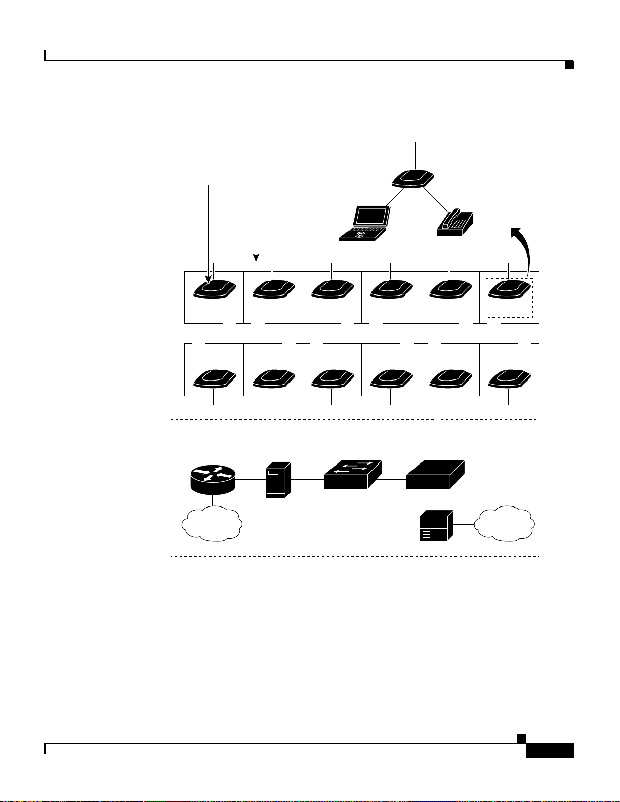
In a typical installation, CPEs are installed in rooms of a multidwelling tenant
building. The CPE data rates and profile settings are controlled by a
Catalyst 2912 LRE XL or 292 4 LRE XL sw itch. Figu re 1-1 shows a ty pical L RE
installation.
Cisco 575 LRE CPE Hardware Installation Guide
1-2
78-11469-01
Page 21
Chapter 1 Overview
Features
Figure 1-1 Typical LRE Installation
CPEs
installed in separate
building units
Up to 4921 feet
(1500 meters)
existing
telephone wire
CPE CPE CPE CPE CPE CPE
CPE
Internet
router
Management
Cisco 575 LRE
CPE
POTS
Telephone
CPE CPE CPE CPE CPE
Cisco
LRE 48 POTS
gateway
Splitter
Internet PSTN
For installationswhere telephone serviceswill be routed to a P BX switch, you can
install a Cisco LRE POTS Splitter (PS-1M-LRE-48). For more information abo ut
this POTS splitter, r efer to the Installation Notes for the Cisco LRE 48 POTS
Splitter.
If the building does not use a PBX and telephon e services are se nt directly to a n
outside PSTN, you need to provide a ho mologa ted POTS spl itter. For mo re
information about homologated POTS sp litt ers, contact your Cisco sa les
representative.
78-11469-01
Catalyst
2912 LRE XL
switch
PBX
Cisco 575 LRE CPE Hardware Installation Guide
50148
1-3
Page 22
Front-Panel Description
For more information about installing a Catalyst 2900 LRE XL switch, refer t o
the Catalyst 2900 S eries XL Hardware Installati on Guide.
Front-Panel Description
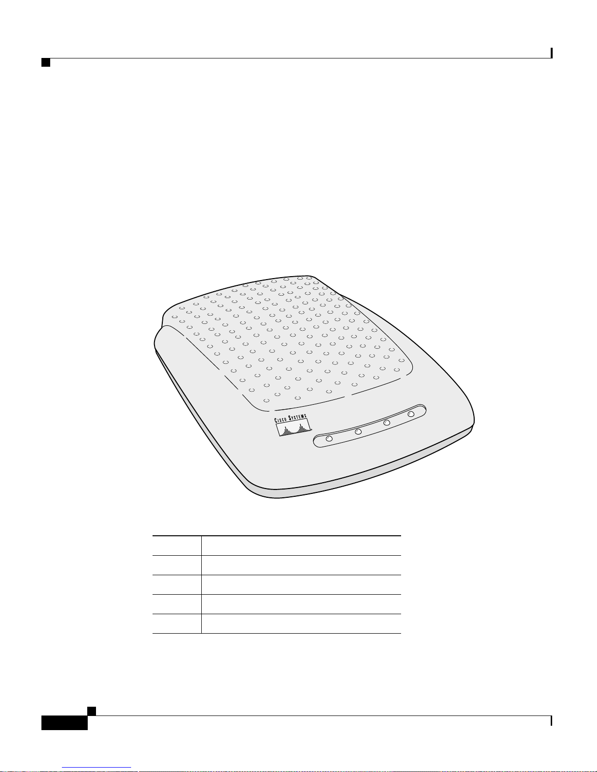
Figure 1-2 shows the front -panel of t he CPE. Table 1-1 lists the front-panel LEDs
and their meanings.
Figure 1-2 Front-Panel of the CPE
Chapter 1 Overview
Table 1-1 CPE Front Panel LEDs
LED Function
READY
ACT
ETH
POWER
LRElinktobaseswitchOK
Ethernet activity
Ethernet link OK
Power indicator
READY
ACT
Cisco 575 LRE
POWER
ETH
45066
Cisco 575 LRE CPE Hardware Installation Guide
1-4
78-11469-01
Page 23
Chapter 1 Overview
Rear-Panel Description
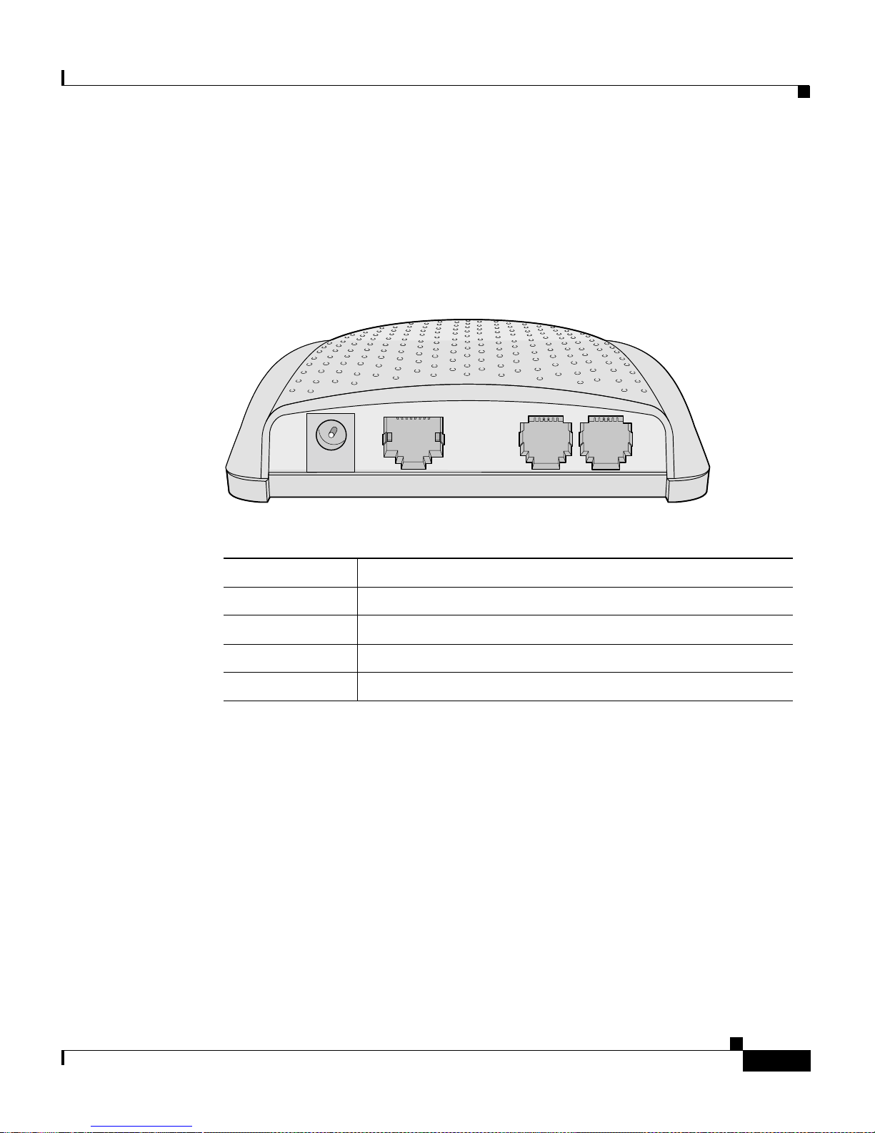
Figure 1-3 shows the rear-panel of th e CPE. Table 1-1 lists the rear-panel
connector jacks and their descriptions.
Figure 1-3 Rear-Panel of the CPE
Rear-Panel Description
PWR
Table 1-2 Rear-Panel Connectors
ENET
Connector Label Connector D escription
PWR
ENET
WALL
PHONE
Power conn ect or
RJ-45 connect or for the Eth er net por t on your PC or laptop
RJ-11 connect or for t he telephone wall jack
RJ-11 connecto r for a telepho ne
WALL
PHONE
44722
78-11469-01
Cisco 575 LRE CPE Hardware Installation Guide
1-5
Page 24

Rear-Panel Descr ipt ion
Chapter 1 Overview
Cisco 575 LRE CPE Hardware Installation Guide
1-6
78-11469-01
Page 25

CHAPTER
2
Installation
This chapter describes how to install your Cisco 575 LRE CPE and interpret the
LEDs to e nsu re proper ope rat ion. Read the topics, and perf orm these pr oced ures
in the order that they are presented:
• Pre-installation information and guidelines
• Installation procedures
• Connection procedures
• Power-on procedure s
• Where to go nex t
78-11469-01
Cisco 575 LRE CPE Hardware Installation Guide
2-1
Page 26
Preparing for Inst al la tion
Preparing for Installation
Note If you mount the C PE unde r a de sk or on a wall, use the scre ws s upplie d with
the CPE.
Tips You can install the CPE on or under a desk or on a wall. Before you begin the
installation, decide where to mount th e CPE by reviewing the illustrations in
the “InstallingtheCPEOnaDesk”, “In stalling the CPE Under a Desk”,and
“InstallingtheCPEOnaWall” sections later in this chapter.
Chapter2 Installation
Caution There are no serviceable parts inside the unit. Removing screws, cover, or
Warnings
Warning
Warning
Warning
otherwise dismantling the unit voi ds the warranty.
These warni ngs ar e tra ns la ted i n to s ever al l angu age s i n Appendix C, “Translated
Safety Warnings.”
Only trained and qualified personnel should be allowed to install or replace
this equipment.
Read the installation instructions before you connect the system to its power
source.
Before working on equipment that is connected to power lines, remove
jewelry (including rings, necklaces, and watches). Metal objects wil l heat
up when connected to power and ground and can cause serious burns or
weld the metal object to the terminals.
Cisco 575 LRE CPE Hardware Installation Guide
2-2
78-11469-01
Page 27
Chapter 2 Installatio n
Preparing for Installation
Warning
Warning
Warning
Warning
Warning
The plug-socket combination must be accessible at all times because it
serves as the main disconnecting device.
To prevent the system from overheating, do not operate it in an area that
exceeds the maximum recommended ambient temperature of 104°F (40°C).
The device is designed to work with TN power systems.
This product relies on the building’s installation for short-circuit
(overcurrent) protection. Ensure that a fuse or circuit breaker no larger than
120 VAC, 15A U .S. (240 VAC, 10A international) is used on the phase
conductors (all current-carrying conductors).
A voltage mismatch can cause equipment damage and may pose a fire
hazard. If the voltage indicated on the label is different from the power
outlet voltage, do not connect the chassis to that receptacle.
Warning
Do not work on the syst em or connect or disconnect cables during periods
of lightning activity.
Warning
Ultimate disposal of this product should be handled according to a ll national
laws and regulations.
Warning
Unplug the power cord before you work on a system that does not have an
on/off switch.
78-11469-01
Cisco 575 LRE CPE Hardware Installation Guide
2-3
Page 28
Preparing for Inst al la tion
Chapter2 Installation
Warning
The ports labeled “ENET” and “PWR” are safety extra-low voltage (SELV)
circuits. Only connect SELV circuits to other SEL V circuits. The ports labeled
“PHONE" and "WALL" may be connected to telephone network voltage (TNV)
circuits. Do not connect the SELV circuit to the TNV circuits. To avoid
electric shock, do not connect safety extra-low voltage (SELV) circuits to
telephone network voltage (TNV) circuits. Although the ENET ports use
RJ-45 connectors that will accept RJ-11 telephony plugs, TNV circuits must
not be connected to the ENET ports. Use caution when connecting cables.
EMC Regulatory Statements
U.S.A.
U.S. regul atory informa tion for this pro duct is in the front matter of this manual.
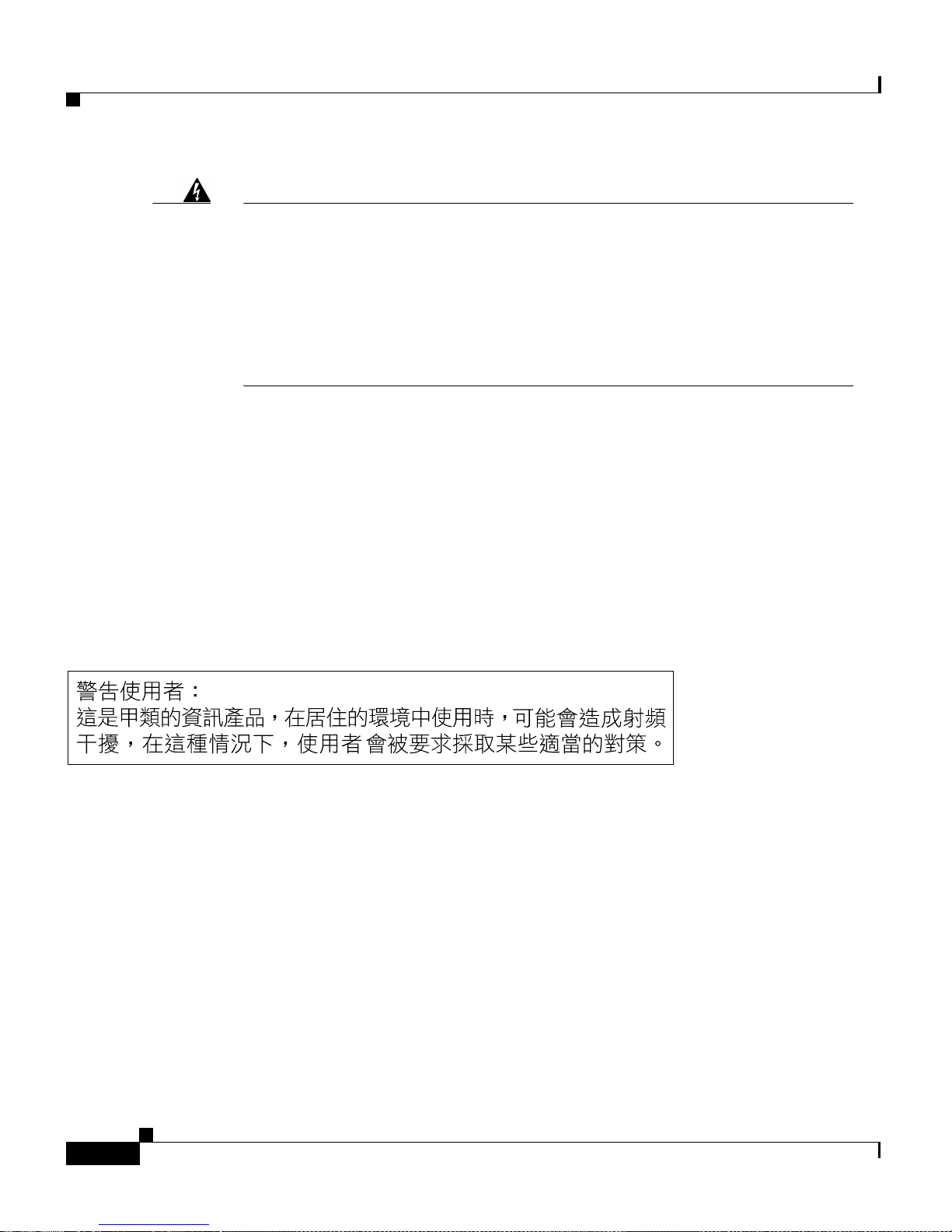
Taiwan
Package Contents
When you unpack the CPE, be sure that the package contains the items in the
following list. If any items a re missing, notify your autho riz ed Cisco sales
representative:
• Cisco 575 LRE CPE
• AC power cord and adapter
Cisco 575 LRE CPE Hardware Installation Guide
2-4
5456
78-11469-01
Page 29

Chapter 2 Installatio n
Note The C PE is sold individually or in multipackages of six and twenty-four. The
Installing the CPE On a Desk
• Mounting kit containing these items:
–
Four rubber feet for installing the CPE on a desktop
–
Cable lock for securing cables to the CPE
–
Three numbe r-8 Philli ps pan-h ea d s crew s for mounting the CPE under a
desk or on a wall and attaching cable lock to the CPE
–
Screw tem plat e for aligning screws
• One RJ-45 -to-RJ-45 , straight-throug h Ethernet cable
• Cisco Info rmation Packet, containi ng warranty, safety, and suppor t
information
multipackagesinclude only one hardware installation guide, the release notes,
and the Cisco Information Packet for every six CPEs.
Installing the CPE On a Desk
Step 1 Locate t he adhesive strip wi th the ru bber feet in the CPE mo unting -kit .
Step 2 Remove the four rubber feet from the adhesive strip and attach them to the
recessed areas on the bo tto m of the unit. This p revent s the CPE from sliding on
the desktop.
Step 3 Place the CPE on the desktop.
Installing the CPE Under a Desk
Tips We recommend that you attach the Ethernet, telephone, and power cables to
the CPE before mounting it und er a d esk becau se the c on nector s are h idde n
from view after the CPE i s installed. For more information , see the connection
procedures beginning on page 12.
78-11469-01
Cisco 575 LRE CPE Hardware Installation Guide
2-5
Page 30
Installing the CPE Under a Desk
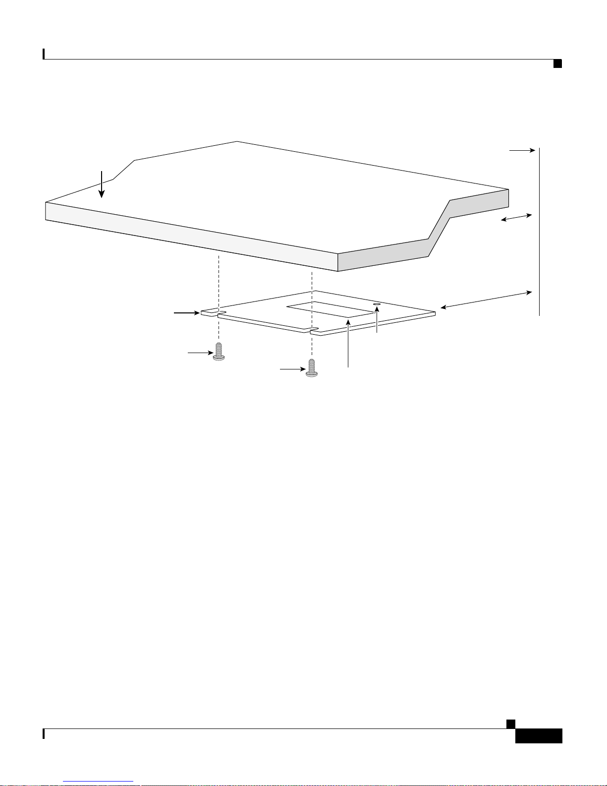
Step 1 Position the desk so that it is at least 1/2-inch (12.7 millimeters) f rom the wall to
allow space for the Ethernet cable between the wall and the desk. (See Figure 2-1,
Figure 2-2,andFigure 2-7.)
Step 2 Locate the screw template.The template is used to align the mounting screw holes
and is also used as a guide to make sure the screws are installed into the desktop
with proper clearance.
Note The tem pla te has adhesive to hold it in pla ce while you dri ll holes
Step 3 Position the screw template underneath the desk so that the two side-by-side slots
face th e front of the desk (See Figure 2- 1.) This ensures that the cables will face
the rear of the desk after the CPE is installed.
Chapter2 Installation
underneath th e de sk top. I f yo u will be usin g th e s ame screw templ ate
to install several CPEs, do not us e t he a dhesive . I n this case, hold the
template ag ains t the bottom of the desk while you dri ll the screw holes
and in ser t the scews.
Note Do not attach the screw template to the desk yet.
Note Allow a minimum of three inches (7.6 centimeters) between the rear
of the desk and the scr ew template so that there is enough room for the
cables to clear the wall. (See Figure 2-1.)
Cisco 575 LRE CPE Hardware Installation Guide
2-6
78-11469-01
Page 31
Chapter 2 Installatio n
Figure 2-1 Installing the Mounting Screws Under a Desk
Desktop
Installing the CPE Under a Desk
Wall
at least
1/2 in.
(12.7 mm)
Screw template
3 in.
(7.6 cm)
Cable
lock hole
Adhesive
Step 4
Screw
Screw
Peel the adhesive strip off the bottom of the screw template, and attach it to the
underside of the desk.
Step 5 Use a 1/44-inch bit to drill a 1/2-inch-deep hole in th e two screw template slots.
Step 6 (Optional) If you wish to attach the cable lock after the cables are installed, drill
a 1/2-inc h-dee p hole in the cable lock hol e. For more info rmation, see the
“Attaching the Cable Lock” sectiononpage2-16.
Step 7 Insert two screws i n the slots on the screw t empla te, and tigh ten until t hey touch
the top of the screw template.
Step 8 Remove the screw template from underneath the desk.
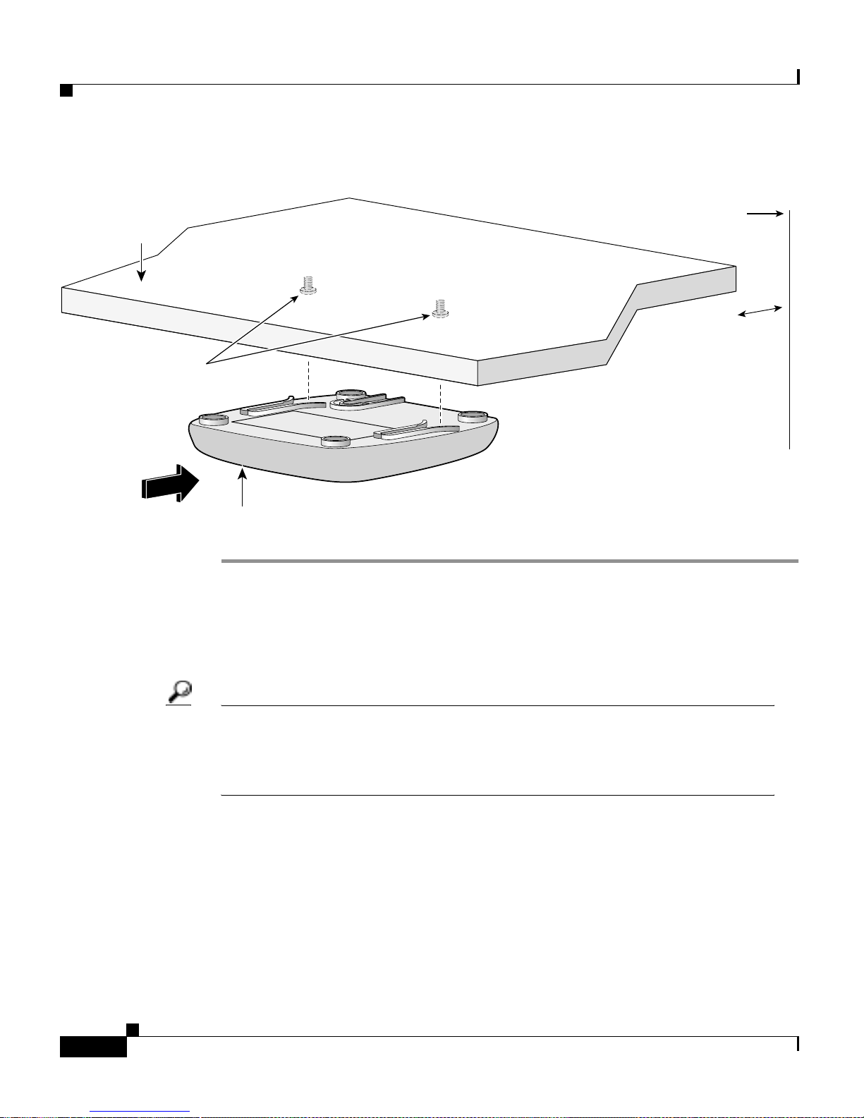
Step 9 Slide the CPE onto the mounting screws until it locks in place. (See Figure 2-2.)
47502
78-11469-01
Cisco 575 LRE CPE Hardware Installation Guide
2-7
Page 32
Installing the CPE On a Wall
Figure 2-2 Mounting the CPE Under a Desk
Desktop
Screws mounted to
underside of desk
Slides on
this way
Chapter2 Installation
Wall
at least
1/2 in.
(12.7 mm)
CPE
Installing the CPE On a Wall
Tips We recommend that you attach the Ethernet, telephone, and power cables to
the CPE before mounting it on wall because the connectors might be hidde n
from view after the CPE i s installed. For more information , see the connection
procedures beginning on page 12.
53024
Cisco 575 LRE CPE Hardware Installation Guide
2-8
78-11469-01
Page 33
Chapter 2 Installatio n
Step 1 Locate the screwtemplate. The template is used to align the mounting screw holes
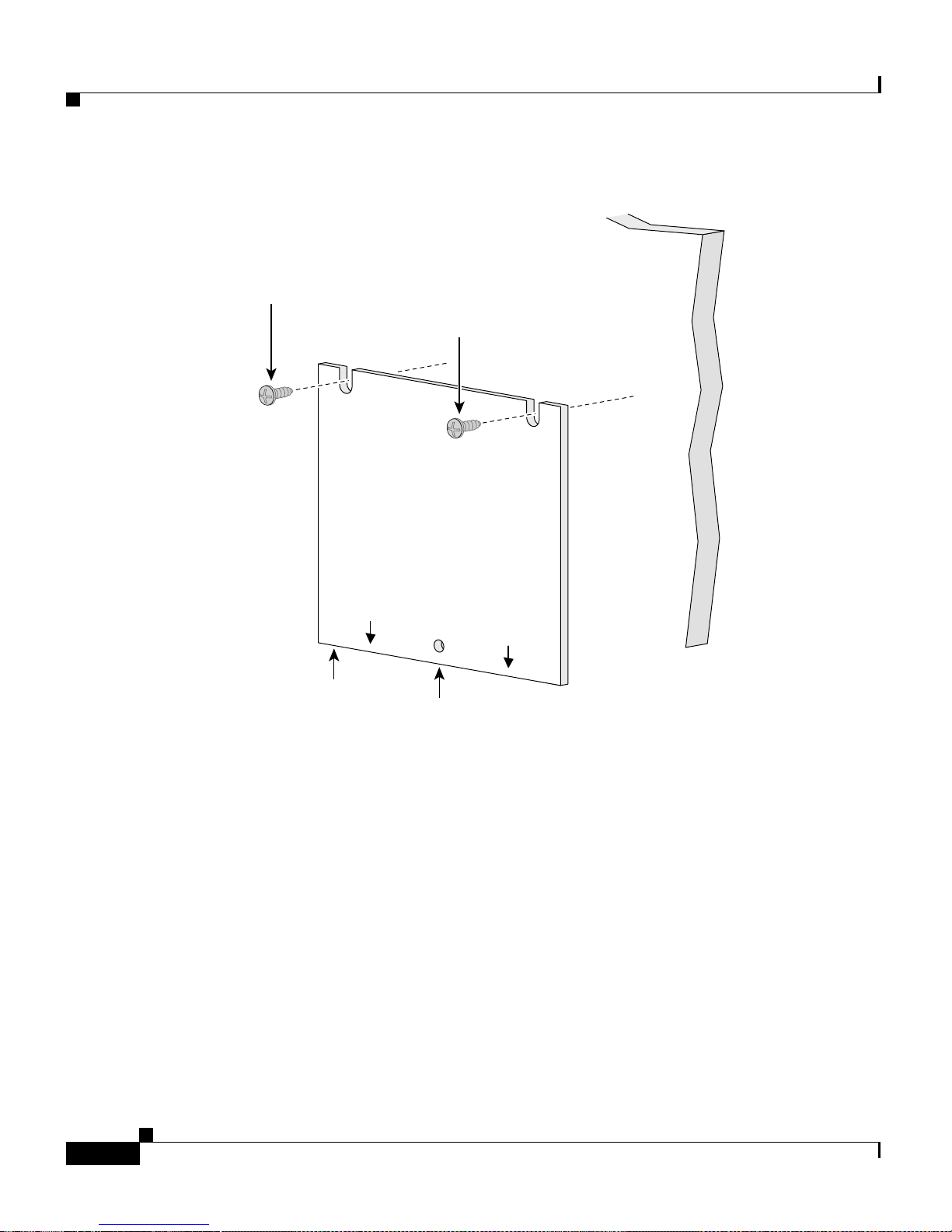
Step 2 Positionthe screw template so thatthe two side-by-sideslots are facing awayfrom
Installing the CPE On a Wall
and is also used as a guide to make sure the screws are installed into the desktop
with proper clearance.
Note The tem pla te has adhesive to hold it in pla ce while you dri ll holes
underneath th e de sk top. I f yo u will be usin g th e s ame screw templ ate
to install several CPEs, do not us e t he a dhesive . I n this case, hold the
template i n place with yo ur hand while you drill the screw ho les and
insert the screws.
the floor. (See Figur e 2-3.) This ensures the cables will face towards th e floor
after t hey are connected .
Note Do not attach the screw template to the wall yet.
78-11469-01
Cisco 575 LRE CPE Hardware Installation Guide
2-9
Page 34
Installing the CPE On a Wall
Figure 2-3 Installing the Mounting Screws On a Wall
Screw
Chapter2 Installation
Screw
P/N 700-09589-01
SCREW TEMPLATE
MOUNTING SURFACE
THIS SIDE AWAY FROM
SIDE
CABLE ENTRY
SIDE
CABLE ENTRY
47503
Screw
template
Cable
lock hole
Step 3
Peel the adhesive strip off the bottom of the screw template.
Step 4 Attach the screw template to the wall.
Step 5 Use a 1/44-inch bit to drill a 1/2-inch-deep hole in th e two screw template slots.
Step 6 (Optional) If you wish to attach the cable lock after the cables are installed, drill
a 1/2-inc h-deep hole in the screw template hole. For more information, see the
“Attaching the Cable Lock” sectiononpage2-16.
Step 7 Insert two screws i n the slots on the screw t empla te, and tigh ten until t hey touch
the top of the screw template.
Step 8 Remove the screw template from the wall.
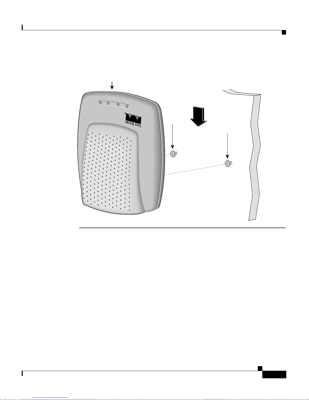
Step 9 Slide the CPE ont o the scre ws until it locks in pla ce. (See Figu re 2-4.)
Cisco 575 LRE CPE Hardware Installation Guide
2-10
78-11469-01
Page 35
Chapter 2 Installatio n
Installing the CPE On a Wall
Figure 2-4 Installing the CPE On a Wall
CPE
E
W
R
O
P
T
E
N
R
E
H
T
E
Y
T
I
V
I
T
C
A
N
A
W
L
5
R
7
E
5
o
c
s
i
C
CPE slides on
this way
Screw
Screw
53023
78-11469-01
Cisco 575 LRE CPE Hardware Installation Guide
2-11
Page 36
Connecting to a PC or Laptop
Connecting to a PC or Laptop
Follow these steps to connect the CPE to a PC or lapt op:
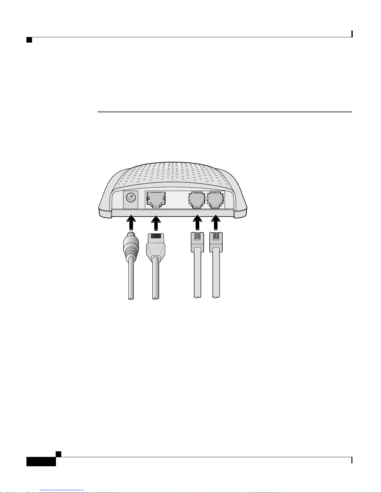
Step 1 Connect one end of the incl uded Ethernet cable to the ENET port of the CPE. (See
Figure 2-5.)
Figure 2-5 Connecting Cables to the CPE
Chapter2 Installation
Step 2
PWR
To
AC
power
ENET
To
PC or
laptop
WALL
To
wall
jack
PHONE
To
telephone
44723
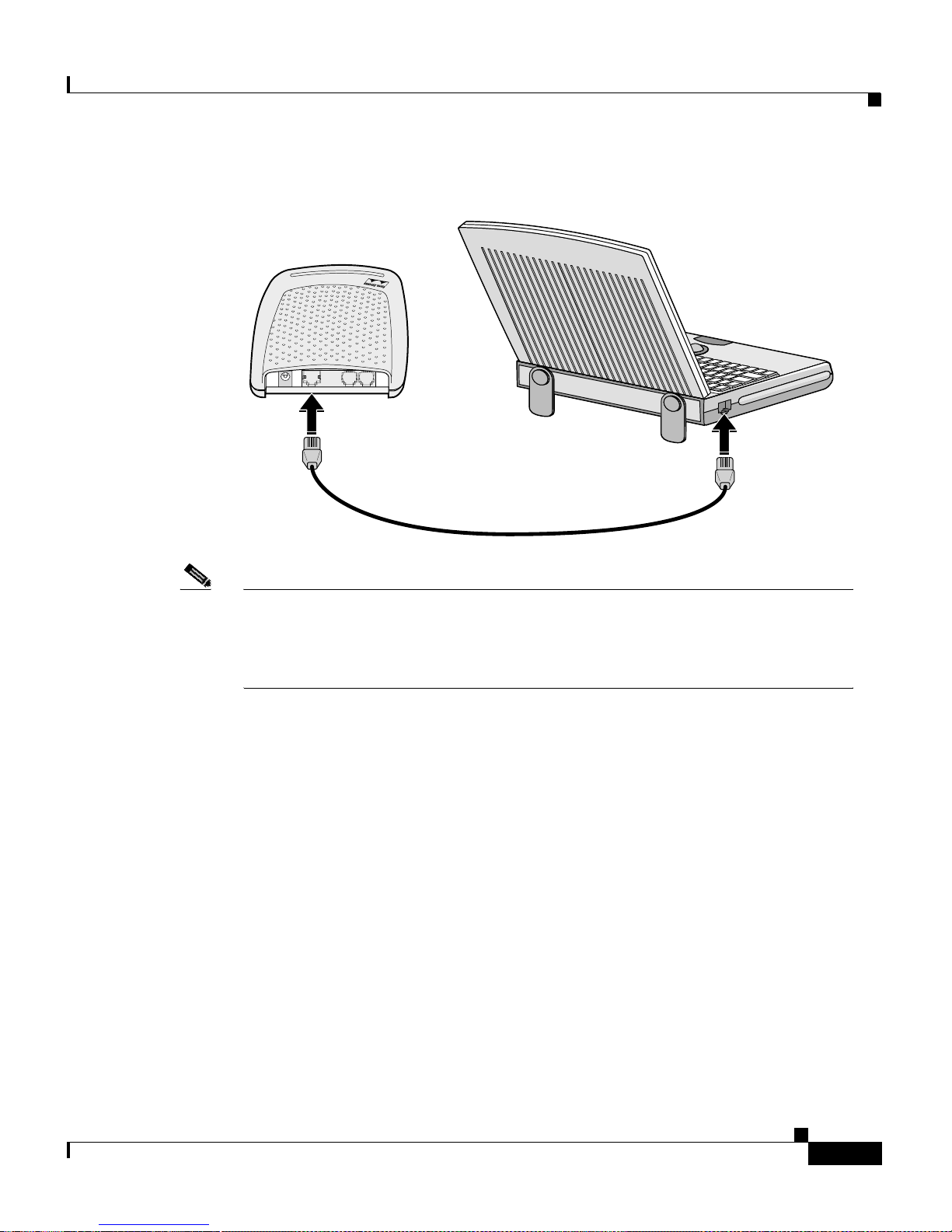
Connectthe other end of the Ethernetcable to the RJ-45 connectorof the Ethernet
card in your PC or laptop. (See Figure 2-6.)
Cisco 575 LRE CPE Hardware Installation Guide
2-12
78-11469-01
Page 37
Chapter 2 Installatio n
Connecting to a PC or Laptop
Figure 2-6 Connecting the CPE to a Computer
PWR
WALL
ENET
PHONE
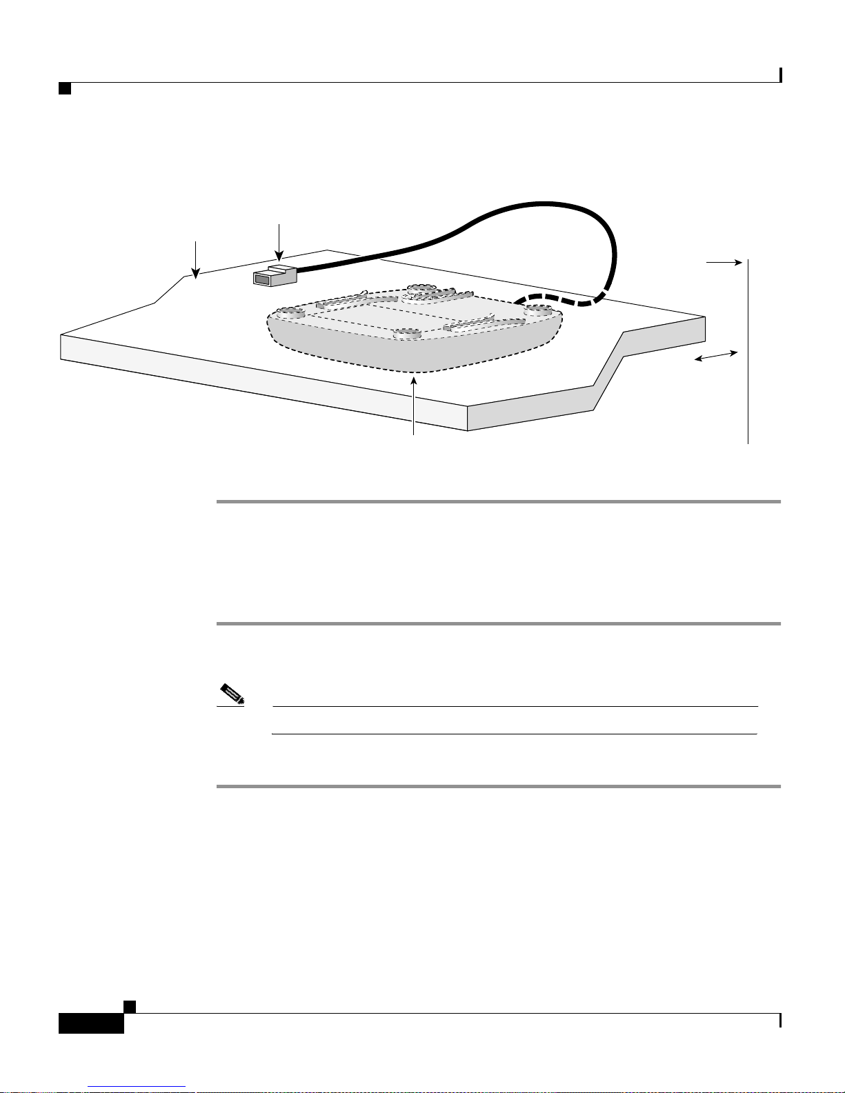
Note If you are installing several CPEs in different rooms of a building, laptop or
desktop com pute rs might no t yet be availa ble. If th is is the case, c onn ect one
end of the Ethernet cable to the CPE and leave the other end of the Ethernet
cable on top of the desk. (See Figure 2 -7.)
45064
78-11469-01
Cisco 575 LRE CPE Hardware Installation Guide
2-13
Page 38
Connecting to a Wall-Mo unted Telephone Jack
Figure 2-7 Ethernet Cable Lying On Desktop
Connect
to PC
Desktop
attached under
CPE
a desk
Chapter2 Installation
Wall
1/2 in.
(12.7 mm)
from wall
45783
Connecting to a Wall-Mounted Telephone Jack
Step 1 Connect o ne end of a teleph one cord (not included) to the WALL p ort of the C PE.
(See Figur e 2-5.)
Note Use a standard telephone cord w it h RJ-11 connectors on b oth ends.
Step 2 Connect the othe r end of the telephone cord to the telep hon e jack in the wall.
Cisco 575 LRE CPE Hardware Installation Guide
2-14
78-11469-01
Page 39
Chapter 2 Installatio n
Connecting to a Telephone
Step 1 Connect one end of a telephone cord (not included) to the PHONE port of the
CPE. (See Figure 2-5.)
Note Use a standard telephone cord w it h RJ-11 connectors on b oth ends.
Step 2 Connect the other end of the teleph one cord to a telephone.
Note If you have other telephones that share t he same line but that are not
connected through the C PE, we recommend connect ing those
telephones through a microfilter with a 300-Ohm termination.
Microfilters can improve voice call quality when voice and data
equipment are us in g the same tele ph one line. They also pre vent
nonfiltered telephone rings or nonfiltered telephone transitions (such
as on-ho ok to o ff-hook ) from interruptin g the LRE con nect ion . For
more information about microfilters, contact your Cisco sales
representative.
Connecting to a Telephone
Connecting the Power Cord
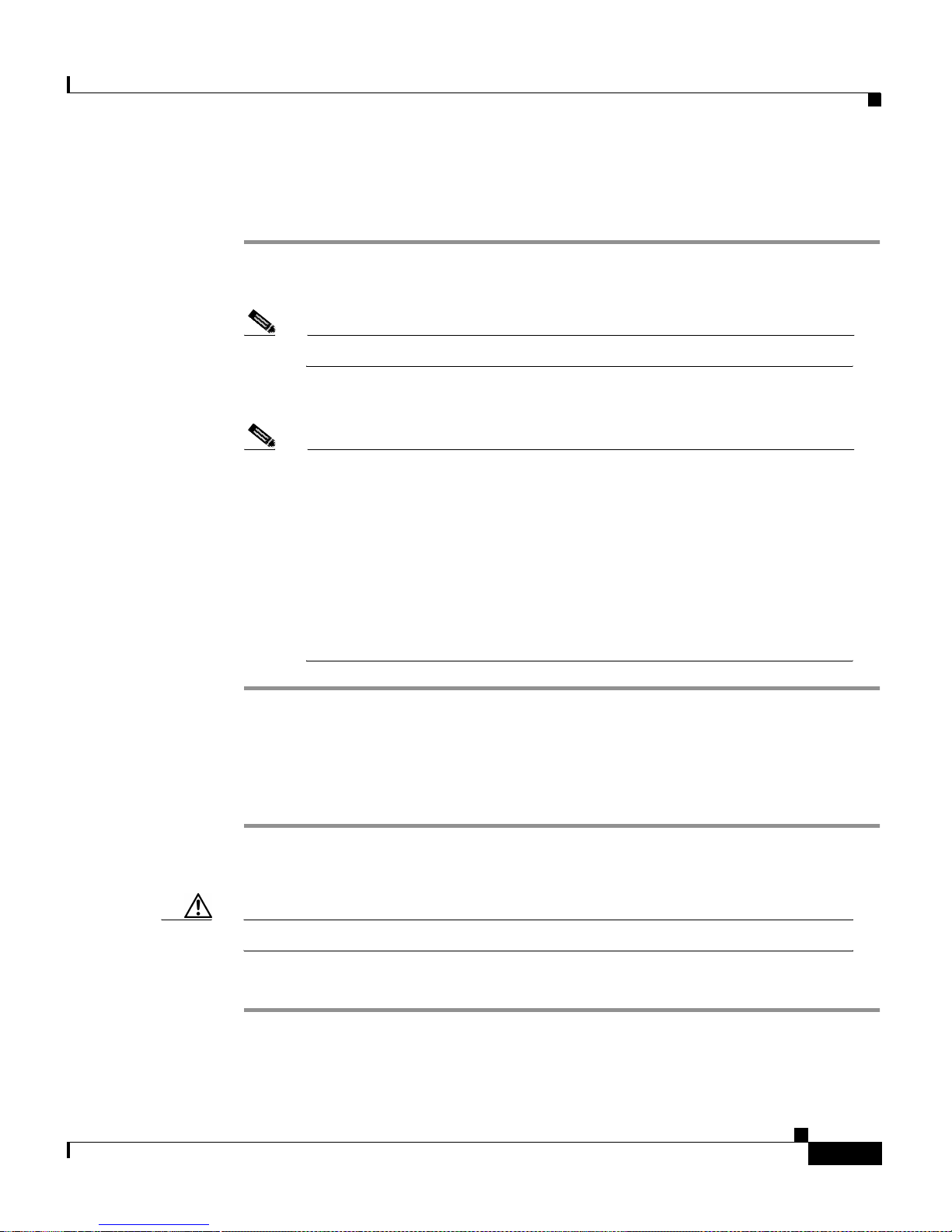
Step 1 Connect the power cord to th e power connector on the CPE rear pane l. See
(Figure 2-5.)
Caution Use onl y the AC power cord and ad apter shipped with t he CPE.
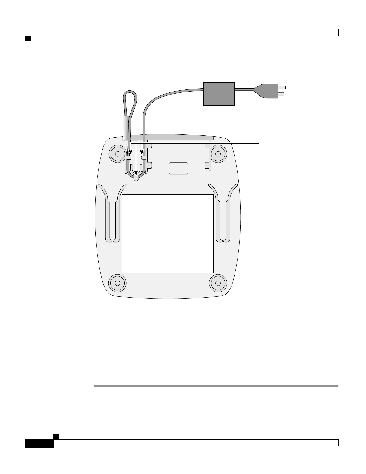
Step 2 Slide the power cord under the hooks on the bo ttom of the CPE. (See Figure 2-8.)
78-11469-01
Cisco 575 LRE CPE Hardware Installation Guide
2-15
Page 40
Attaching the Cable Lock
Chapter2 Installation
Figure 2-8 Securing Power Cord to Bottom of the CPE
To electric
outlet
Hooks
Attaching the Cable Lock
The optional cable lock provides extra security to prevent someone from easily
removing the CPE.
To install the cable lock, follow these steps:
Step 1 Locate the cable lock in the accessory k it.
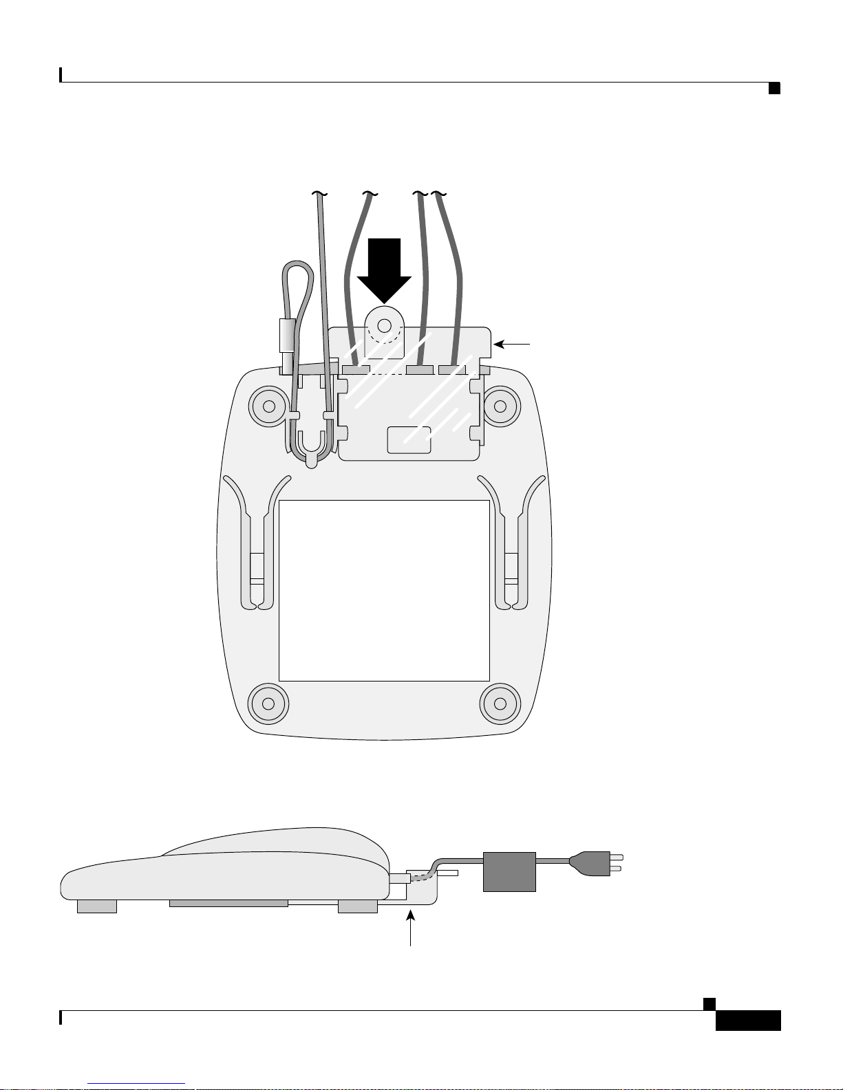
Step 2 Slide the cable lock ont o the CPE until it clic ks in plac e. (See Figure 2-9 and
Figure 2-10.)
Cisco 575 LRE CPE Hardware Installation Guide
2-16
45782
78-11469-01
Page 41
Chapter 2 Installatio n
Attaching the Cable Lock
Figure 2-9 Attaching the Cable Lock
Cable lock
Figure 2-10 Cable Lock Installed on CPE (Side View)
78-11469-01
Cable lock
Cisco 575 LRE CPE Hardware Installation Guide
46014
To electric
outlet
46775
2-17
Page 42
Attaching the Cable Lock
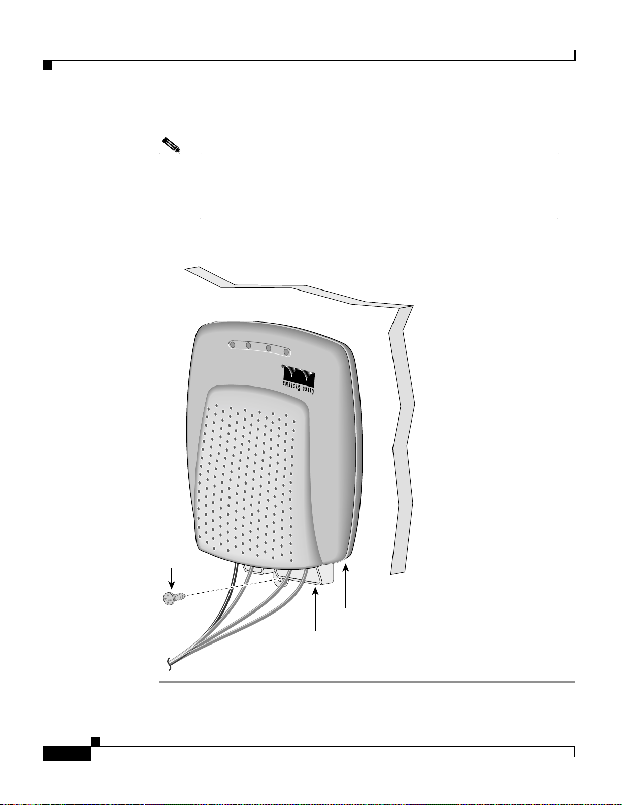
Step 3 Insert the supplied screw into the cable-lock mounting hole. (See Figure 2-11.)
Chapter2 Installation
Note We do not recommend drilling a hole for the cable lock if the CPE is
sitting on top o f a desk. The cable lock can still be installed into the
CPE if it is mounted onto a desktop. Simply sli de the ca ble lock into
theCPEandsnapitintoplace.
Figure 2-11 Securing the Cable Lock with Mounting Screw
W
E
R
O
P
H
T
E
T
C
A
Y
D
A
E
R
L
5
R
7
E
5
o
c
s
i
C
Screw
Cisco 575 LRE CPE Hardware Installation Guide
2-18
48001
CPE
Cable lock
78-11469-01
Page 43

Chapter 2 Installatio n
Powering On the CPE
Step 1 Connect the AC cord to a power outlet.
Step 2 Ensure that the power LED turns gre en. If the pow er LED does not turn green,
refer t o Chapter 3, “Troubleshoo ting” to determine a c ourse of a ct ion.
The READY link and ETH link LEDs tur n on w hen the appropriate equ ip ment i s
connected.
Where to Go Next
Powering On the CPE
CPE configur ati on, data speed settings, and mon itor ing are controlled from a
Catalyst 291 2 LRE XL or Ca talyst 2924 LRE XL switch. Refer to the Catalyst
2900 Ser ies XL and Catalyst 3500 Series XL Software Confi guratio n Guide for
additional information .
78-11469-01
Cisco 575 LRE CPE Hardware Installation Guide
2-19
Page 44

Where to Go Next
Chapter2 Installation
Cisco 575 LRE CPE Hardware Installation Guide
2-20
78-11469-01
Page 45

CHAPTER
3
Troubleshooting
The LEDs on t he CPE pr ovide troublesho oting inform ation. They show fa ilure s
with power, port-conn ec tivi ty proble ms, and over all CPE per forma nce. For a full
description of the LEDs, see t he “Front-Panel Description” section on page 1-4.
The LRE link between the C PE and t he Catalyst 2900 LRE XL switc h can be
monitored from t he switch. Fo r more information, refer to the Catalyst 2900
Series XL and Catalyst 3500 Ser ies XL Software Configu ration Guide.
Table 3 -1 lists the CPE problems that you might encounter and their solutions.
78-11469-01
Cisco 575 LRE CPE Hardware Installation Guide
3-1
Page 46
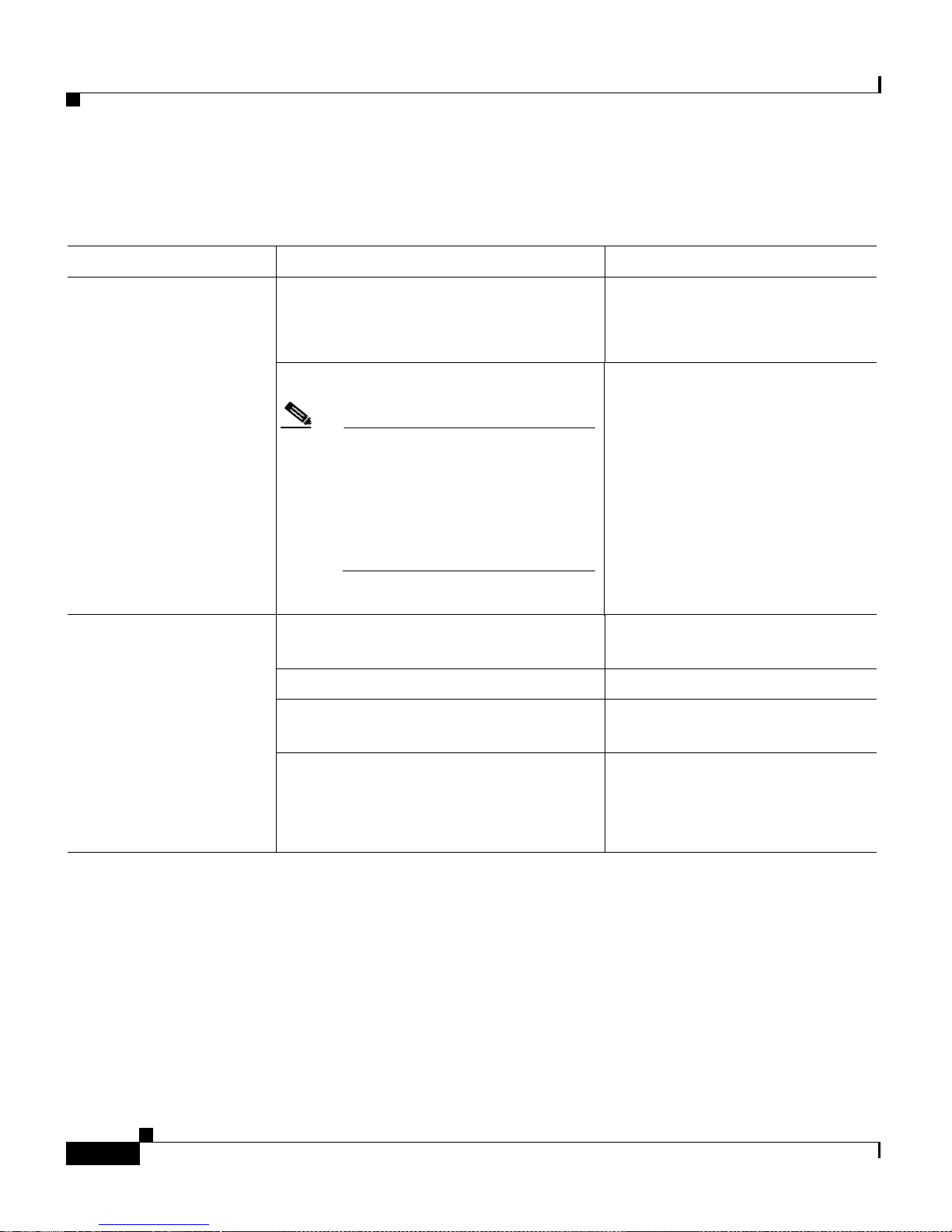
Table 3-1 Common Problems and Their S olutio ns
Symptom Possible Caus e Resolution
Chapter3 Troubleshooting
POWER LED not turned on
READY LED not turned on
AC power adapter and cable is loose or
not plug ged in pr operl y.
Reconnectthe poweradapter and
cable into t he w all socket and the
CPE.
Defective AC power adapter and ca ble .
Replace the A C power adapte r
and cable.
Note Donotattempttoopenor
repair the powe r adapter.
Replace the AC power
adapter and cabl e only with
a newone ordered fromyour
Cisco sales representative.
Telephone cab le is loos e or is not
connected properly.
Reconnect the phone cable into
the phone wall jack and CPE.
Telephone c able is defective. Replace the tel ephone cable .
Cable tru nking is d efect ive. Repair the cable trunking or
select an a l te rn ati ve pai r.
CPE is n ot communicating w ith, or
might be attempting to exceed the
bandwidth selected by, the Catalyst
2900 LRE XL swit ch.
Cisco 575 LRE CPE Hardware Installation Guide
3-2
Verify switch and ups trea m
network status.
78-11469-01
Page 47
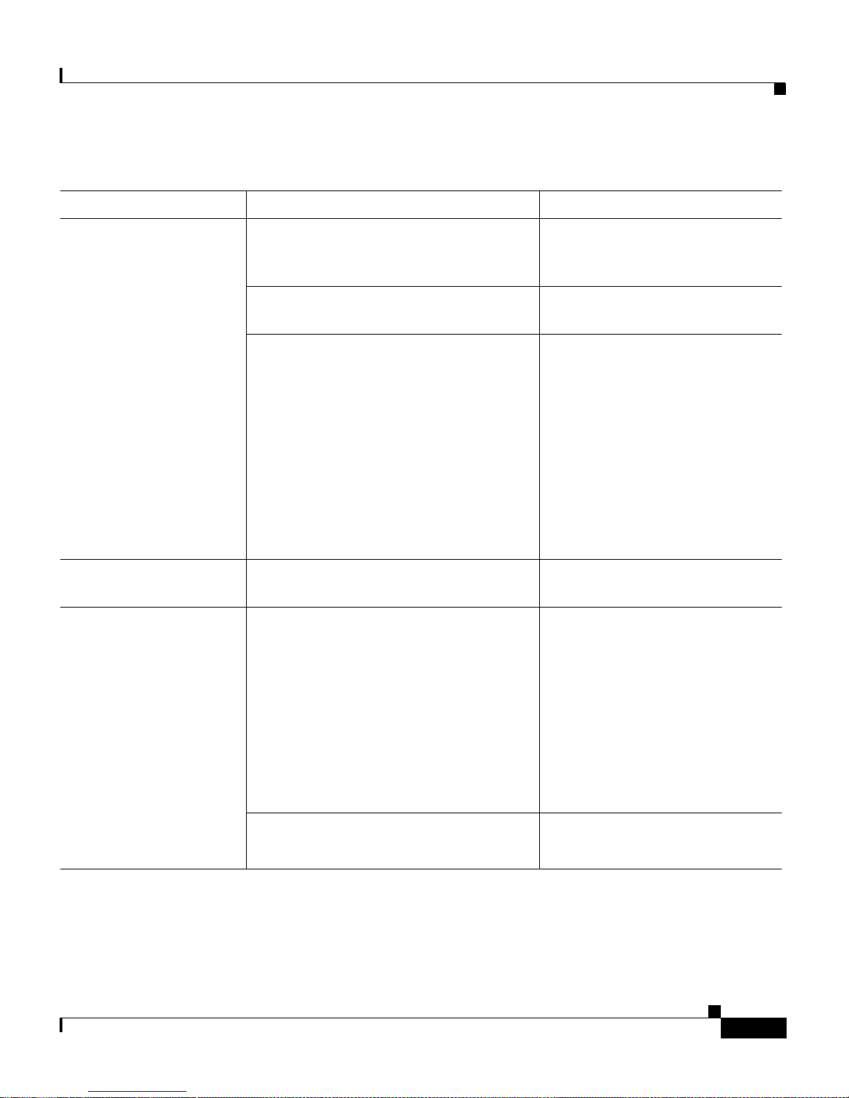
Chapter 3 Troubleshooting
Table 3-1 Common Problems and Their Solut io ns (continued)
Symptom Possible Caus e Resolution
ETH LED not turned on
ACTIVITY LED no t blinking.
No Connectivity.
Ethernet cable i s loose or is not
connected properly.
CPE is not communicating with the
Ethernet card in your PC or laptop.
Incorrect or defective Ethernet cable.
• A crossover cable was used instead
of the included straight-throu gh
cable.
• The Ethernet cable is wired
incorrectly or is defective.
Data not being transferred between the
CPE and PC or laptop
Incorrect or ba d Etherne t cable.
Reconnect the Ethernet cable
into the CPE and your PC or
laptop.
Reboot you r PC or laptop.
• For the correct pinouts and
the proper application of
straight-through cables, see
the “Straight -Thro ugh Ca ble
Pinouts” section on
page B-3.
• Replace with a tested good
cable.
Verify laptop or PC network
configuration.
78-11469-01
• A crossover cable was use d when a
straight-through cable was required
or vice-versa .
• For the correct pinouts and
the proper application of
straight-through cables, see
the “Straight -Thro ugh Ca ble
Pinouts” section on
• The Ethernet cable is wired
incorrectly or is defective.
page B-3.
• Replace with a tested good
cable.
Data service unavailable. Verify switch and upstream
network status.
Cisco 575 LRE CPE Hardware Installation Guide
3-3
Page 48

Chapter3 Troubleshooting
Cisco 575 LRE CPE Hardware Installation Guide
3-4
78-11469-01
Page 49
APPENDIX
A
Technical Specifications
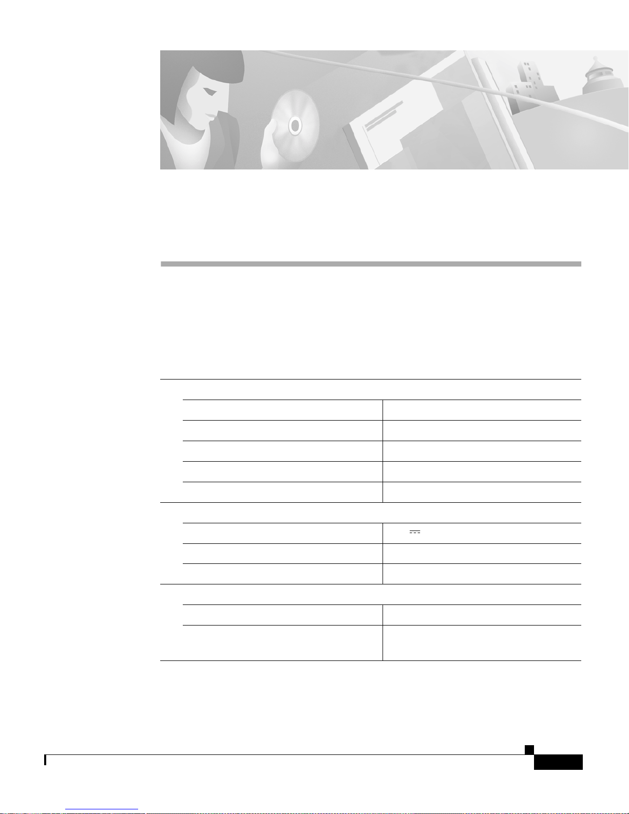
Table A-1 lists the technical specificat ions for the Cisco 575 LRE C PE, and
Table A-2 lists the agency approvals for EMI and safety.
Table A-1 Technical Specifications for the Cisco 575 LRE CPE
Environmental Ranges
Operating temperature 32 to 113°F(0to45°C)
Storage temperature –13 to 158°F(–25 to 70°C)
Relative h umid ity 10 to 85% (n oncon den sing)
78-11469-01
Operating altitude Up to 10,000 ft (3,000 m)
Storage altitude Up to 15,000 ft (4,570 m)
Power Requirements
DC input voltages +5V @1A
AC input voltage 100–240 VAC, 50–60 Hz
Power co nsumpt ion 5W (maxi mum)
Physical Dimensions
Weight 1.1lb(0.5kg)
Dimensions(HxWxD) 1.7x5x6in.
(4.3 x 12.7 x 15.2 cm)
Cisco 575 LRE CPE Hardware Installation Guide
A-1
Page 50
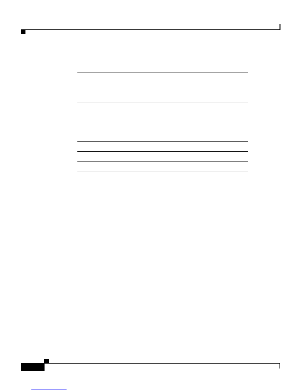
Appendix A Technical Speci fications
Table A-2 Cisco 575 LRE CPE Agency Approvals
Safety EMI
UL 1950 /CSA 22.2
FCC Part 15 Class B
No. 950
IEC 950/EN 60950 EN 5 5022 Class B (CISPR 22 Class B)
AS/NZS 3260, TS 001 VCCI Cl ass B
CE AS/NZS 3548 Cl ass B
BCIQ
CE
CCIB/CCEE CCIB/CCEE
NOM019-1988
Cisco 575 LRE CPE Hardware Installation Guide
A-2
78-11469-01
Page 51
APPENDIX
Connector and Cable Specifications
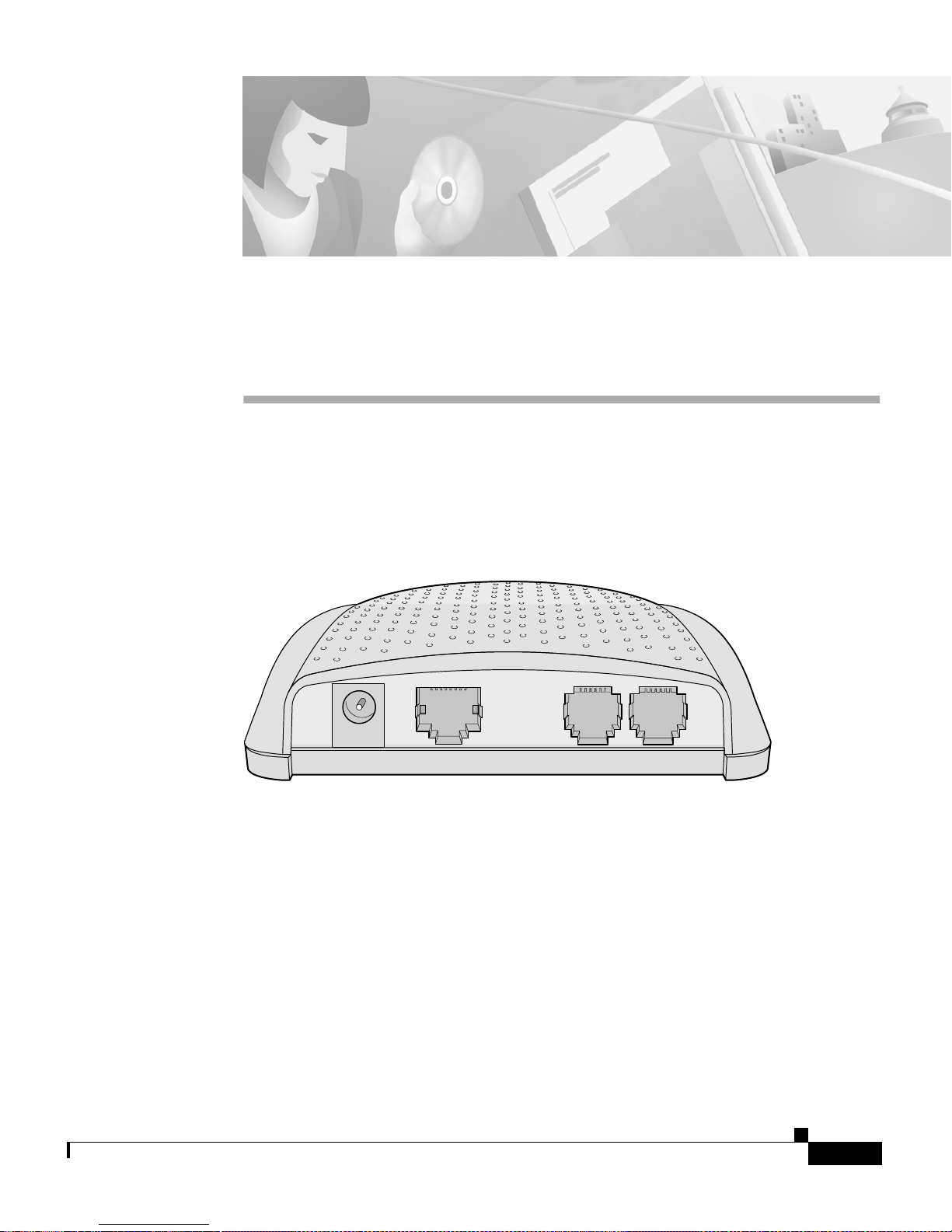
This appe ndix describes the CPE conn ect ors and the cab les that you u se to
connect the CPE to other devices. See Figure B-1.
Figure B-1 CPE Connectors
B
PWR
ENET
Connector Specifications
ENET Port
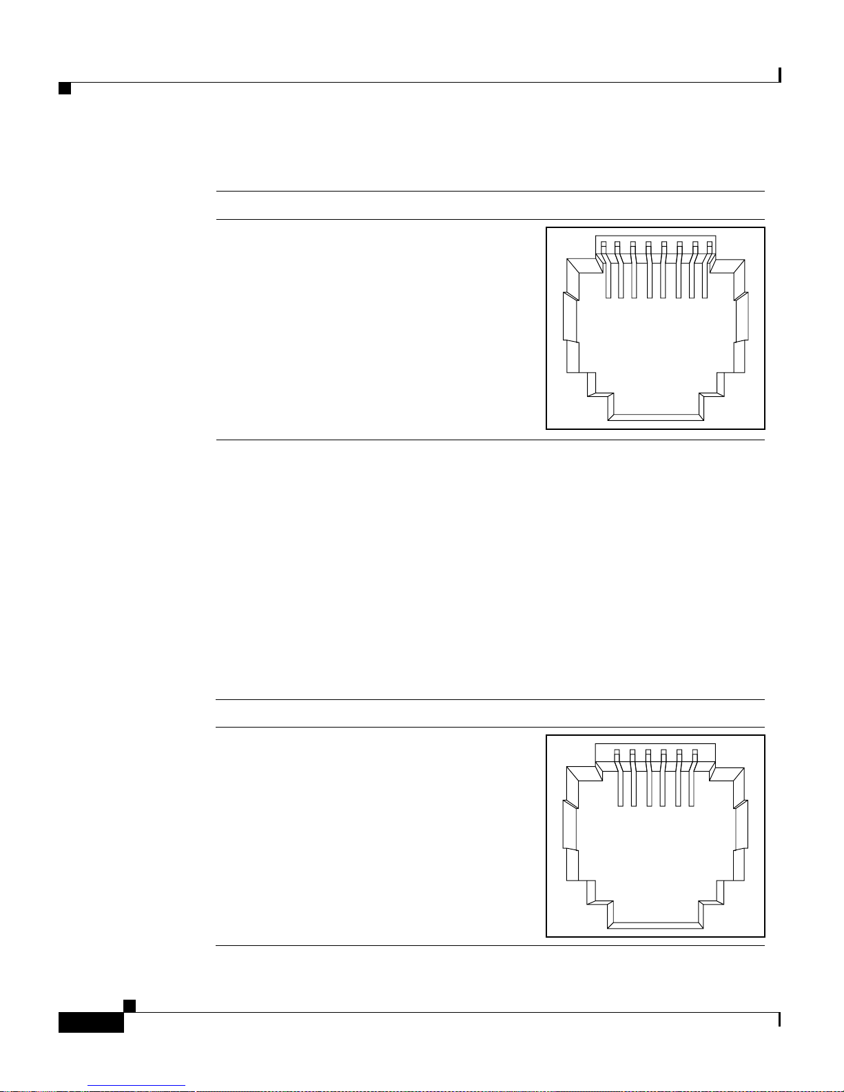
The ENET port is a 10/100 port t hat uses a n RJ-45 connector with Ethernet
pinouts. Th e ENET po rt has the transmit (TD) and rece ive (RD) signals inte rnal ly
crossed so that a stra ight-t hrou gh cable (include d) can be attache d to the port.
Figure B-2 shows the pinou ts.
78-11469-01
WALL
Cisco 575 LRE CPE Hardware Installation Guide
PHONE
44722
B-1
Page 52
Connector Specifications
Appendix B Connector and Cable Specifications
Figure B-2 RJ-45 Connector Pinouts
231 45678Pin Label
WALL Port
1
2
3
4
5
6
7
8
RD+
RDTD+
NC
NC
TDNC
NC
When conne ctin g the EN ET port t o a PC or lapt op, you must use a
straight-through c abl e wire d for 10BASE-T or 100BASE-T.Figure B-5 sh ows the
straight-through cable schematics.
The WAL L port u ses an R J-11 telepho ne co nnect or to c on nect t o the L RE sig na l.
See Figure B-3 for the connector pinouts.
54968
B-2
Figure B-3 RJ-11 WALL Port Connector Pinouts
Pin Label
1
2
3
4
5
6
Cisco 575 LRE CPE Hardware Installation Guide
Pass-through 1
Pass-through 2
LRE tip
LRE ring
Pass-through 5
Pass-through 6
123456
54516
78-11469-01
Page 53
Appendix B Connector and Cable Specifications
PHONE Port
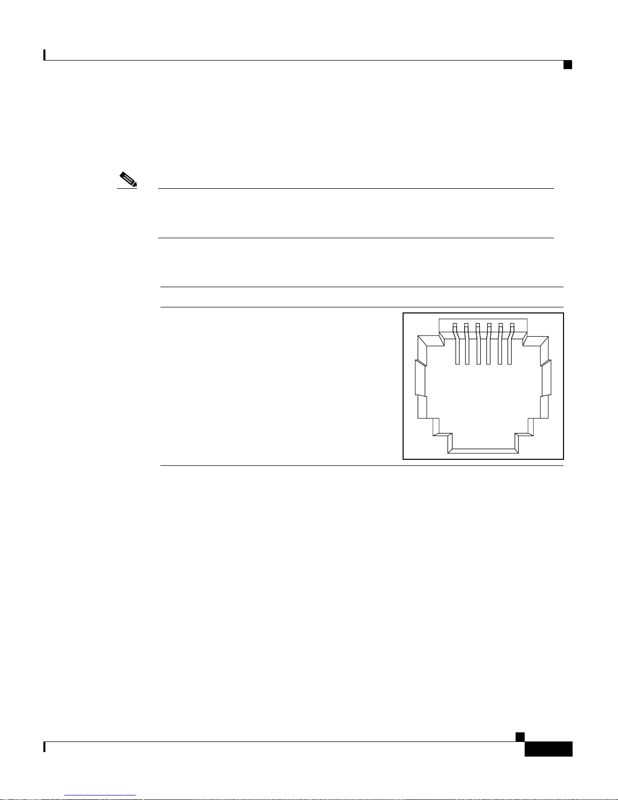
The PHON E port uses an RJ-11 connect or. See Figure B-4 for the pin outs.
Note Pins 1, 2, 5, and 6 on the wall port are con nected internally to the
correspondin g pins o f the ph one port. This allows a second and third phone
pair to pass th rough the CPE witho ut affecting t he LRE c onnec tion.
Figure B-4 RJ-11 PHONE Port Connector Pinouts
Cable Specifications
1
1
2
2
3
4
5
5
6
6
Pass-through 1
Pass-through 2
Phone tip
Phone ring
Pass-through 5
Pass-through 6
Cable Specifications
Straight-Thr ou gh C ab le Pi nou ts
123456
123456Pin Label
517
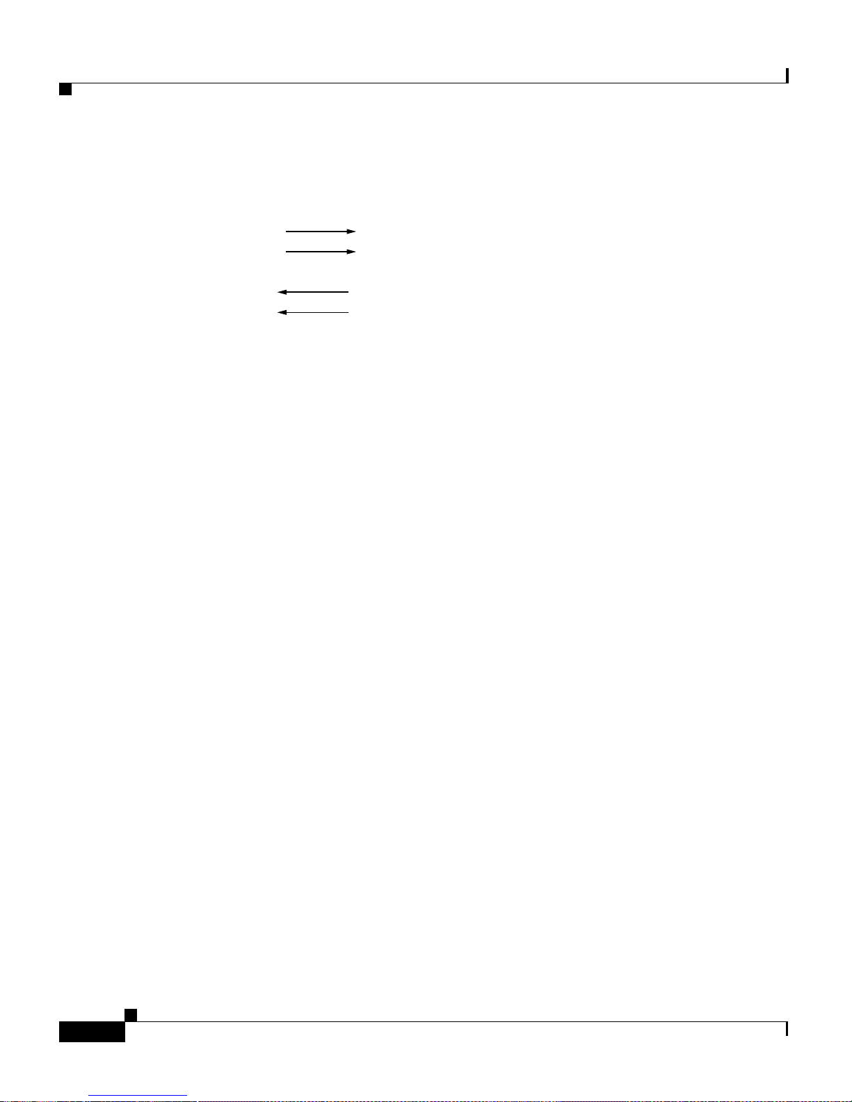
The schem a tics of the stra ight-t hrou gh cable are shown in Figure B -5.
78-11469-01
Cisco 575 LRE CPE Hardware Installation Guide
B-3
Page 54
Cable Specifications
Appendix B Connector and Cable Specifications
Figure B-5 Straight-Through Cable Pinouts
Switch
3 TD+
6 TD–
1 RD+
2 RD–
Switch
3 RD+
6 RD–
1 TD+
2 TD–
H5578
Cisco 575 LRE CPE Hardware Installation Guide
B-4
78-11469-01
Page 55

APPENDIX
Translated Safety Warnings
This appe ndix repeat s in mu ltipl e languages the warnings in t his guide.
C
78-11469-01
Cisco 575 LRE CPE Hardware Installation Guide
C-1
Page 56
Qualified Personnel Warning
Qualified Personnel Warning
Appendix C Translated Safety Warnings
Warning
Waarschuwing
Varoitus
Avertissement
Achtung
Avvertenza
Advarsel
Only trained and qualified personnel should be allowed to install or
replace this equipment
Installatie en reparaties mogen uitsluitend door getraind en
bevoegd personeel uitgevoerd worden.
Ainoastaan koulutettu ja pätevä henkilökunta saa asentaa tai
vaihtaa tämän laitteen.
Tout installation ou remplacement de l'appareil doit être réalisé
par du personnel qualifié et compétent.
Gerät nur von geschultem, qualifiziertem Personal installieren
oder auswechseln lassen.
Solo personale addestrato e qualificato deve essere autorizzato
ad installare o sostituire questo apparecchio.
Kun kvalifisert personell med riktig opplæring bør montere eller
bytte ut dette utstyret.
Aviso
Este equipamento deverá ser instalado ou substituído apenas por
pessoal devidamente treinado e qualificado.
¡Atención!
Estos equipos deben ser instalados y reemplazados
exclusivamente por personal técnico adecuadamente preparado
y capacitado.
Varning
Denna utrustning ska endast installeras och bytas ut av utbildad
och kvalificerad personal.
Cisco 575 LRE CPE Hardware Installation Guide
C-2
78-11469-01
Page 57
Appendix C Translate d Safety Warnings
Installation Warning
Installation Warning
Warning
Waarschuwing
Varoitus
Attention
Warnung
Avvertenza
Advarsel
Read the installation instructions before you connect the system to its
power source.
Raadpleeg de installatie-aanwijzingen voordat u het sy steem met
de voeding verbindt.
Lue asennusohjeet ennen järjestelmän yhdistämi stä
virtalähteeseen.
Avant de brancher le système sur la source d'alimentation,
consulter les directives d'installation.
Lesen Sie die Installationsanweisungen, bevor Sie das System an
die Stromquelle anschließen.
Consultare le istruzioni di installazione prima di collegare il
sistema all’alimentatore.
Les installasjonsinstruksjonene før systemet kobles til
strømkilden.
Aviso
¡Advertencia!
Varning!
78-11469-01
Leia as instruções de instalação antes de ligar o sistema à sua
fonte de energia.
Ver las instrucciones de instalación antes de conectar el sistema
a la red de alimentación.
Läs installati onsanvisningarna innan du kopplar systemet till
dess strömförsörjningsenhet.
Cisco 575 LRE CPE Hardware Installation Guide
C-3
Page 58
Jewelry Rem oval Warni n g
Jewelry Removal Warning
Appendix C Translated Safety Warnings
Warning
Waarschuwing
Varoitus
Attention
Before working on equipment that is connected to power lines, remove
jewelry (including rings, necklaces, and watches). Metal objects will heat
up when connected to power and ground and can cause serious burns or
weld the metal object to the terminals.
Alvorens aan apparatuur te werken die met elektrische leidingen
is verbonden, sieraden (inclusief ringen, kettingen en horloges)
verwijderen. Metalen voorwerpen worden warm wanneer ze met
stroom en aarde zijn verbonden, en kunnen ernstige brandwonden
veroorzaken of het metalen voorwerp aan de aansluitklemmen
lassen.
Ennen kuin työskentelet voimavirtajohtoihin kytkettyjen laitteiden
parissa, ota pois kaikki korut (sormukset, kaulakorut ja kellot
mukaan lukien). Metalliesineet kuumenevat, kun ne ovat
yhteydessä sähkövirran ja maan kanssa, ja ne voivat aiheuttaa
vakavia palovammoja tai hitsata metalliesineet kiinni
liitäntänapoihin.
Ava nt d’accéder à cet équipement connecté aux lignes
électriques, ôter tout bijou (anneaux, colliers et montres compris).
Lorsqu’ils sont branchés à l’alimentation et reliés à la terre, les
objets métalliques chauffent, ce qui peut provoquer des blessures
graves ou souder l’objet métallique aux bornes.
Warnung
Cisco 575 LRE CPE Hardware Installation Guide
Vor der Arbeit an Geräten, die an das Netz angeschlossen sind,
jeglichen Schmuck (einschließlich Ringe, Ketten und Uhren)
abnehmen. Metallgegenstände erhitzen sich, wenn sie an das
Netz und die Erde angeschlossen werden, und können schwere
Verbrennungen verursachen oder an die Anschlußklemmen
angeschweißt werden.
C-4
78-11469-01
Page 59

Appendix C Translate d Safety Warnings
Jewelry Removal Warning
Avvertenza
Advarsel
Aviso
¡Advertencia!
Prima di intervenire su apparecchiature collegate alle linee di
alimentazione, togliersi qualsiasi monile (inclusi anelli, collane,
braccialetti ed orologi). Gli oggetti metallici si riscaldano quando
sono collegati tra punti di alimentazione e massa: possono
causare ustioni gravi oppure il metallo può saldarsi ai terminali.
Fjern alle smykker (inkludert ringer, halskjeder og klokker) før du
skal arbeide på utstyr som er koblet til kraftledninger.
Metallgjenstander som er koblet til kraftledninger og jord blir
svært varme og kan forårsake alvorl ige brannskader eller smelt e
fast til polene.
Antes de trabalhar em equipamento que esteja ligado a linhas de
corrente, retire todas as jóias que estiver a usar (incluindo anéis,
fios e relógios). Os objectos metálicos aquecerão em contacto
com a corrente e em contacto com a ligação à terra, podendo
causar queimaduras graves ou ficarem soldados aos terminais.
Antes de operar sobre equipos conectados a líneas de
alimentación, quitarse las joyas (incluidos anillos, collares y
relojes). Los objetos de metal se calientan cuando se conectan a
la alimentación y a tierra, lo que puede ocasionar quemaduras
graves o que los objetos metálicos queden soldados a los bornes.
Varning!
78-11469-01
Tag av alla smycken (inklusive ringar, halsband och armbandsur)
innan du arbetar på utrustning som är kopplad till kraftledningar.
Metallobjekt hettas upp när de kopplas ihop med ström och jord
och kan förorsaka allvarliga brännskador; metallobjekt kan också
sammansvetsas med kontakterna.
Cisco 575 LRE CPE Hardware Installation Guide
C-5
Page 60
Main Disconnecting Device
Main Disconnecting Device
Appendix C Translated Safety Warnings
Warning
Waarschuwing
Varoitus
Attention
Warnung
Avvertenza
The plug-socket combination must be accessible at all times because it
serves as the main disconnecting device.
De combinatie van de stekker en het elektrisch contactpunt moet
te allen tijde toegankelijk zijn omdat deze het hoofdmechanisme
vormt voor verbreking van de aansluiting.
Pistoke/liitinkohta toimii pääkatkaisumekanismina. Pääsy
siihen on pidettävä aina esteettömänä.
La combinaison de prise de courant doit être accessible à tout
moment parce qu'elle fait office de système principal de
déconnexion.
Der Netzkabelanschluß am Gerät muß jederzeit zugänglich sein,
weil er als primäre Ausschaltvorrichtung dient.
Il gruppo spina-presa deve essere sempre accessibile, poiché
viene utilizzato come dispositivo di scollegamento principale.
Advarsel
¡Advertencia!
C-6
Kombinasjonen støpsel/uttak må alltid være tilgjengelig
ettersom den fungerer som hovedfrakoplingsenhet.
Aviso
A combinação ficha-tomada deverá ser sempre acessível ,
porque funciona como interruptor principal.
El conjunto de clavija y toma ha de encontrarse siempre
accesible ya que hace las veces de dispositivo de desconexión
principal.
Varning!
Man måste alltid kunna komma åt stickproppen i uttaget,
eftersom denna koppling utgör den huvudsakliga
frånkopplingsanordningen.
Cisco 575 LRE CPE Hardware Installation Guide
78-11469-01
Page 61

Appendix C Translate d Safety Warnings
Overtemperature Warning
Overtemperature Warning
Warning
Waarschuwing
Varoitus
Attention
Warnung
To prevent the system from overheating, do not operate it in an
area that exceeds the maximum recommended ambient
temperature of 104°F (40°C).
Om te voorkomen dat het syst eem oververhit raakt, dient u het
systeem niet te gebruiken in een ruimte waar de maximaal
aanbevolen omgevingstemperatuur van 40°C wordt
overschreden.
Jotta järjestelmä ei kuumentuisi liikaa, sitä ei saa käyttää
alueella, jonka lämpöt ila ylittää suosi tellun
maksimiympäristölämpötilan 40°C.
Pour éviter toute surchauffe du système, il est recommandé de
maintenir une température ambiante inférieure à 40°C.
Um das System vor Überhitzung zu schützen, vermeiden Sie
dessen Verwendung in einer Gegend, in der die
Umgebungstemperatur das empfohlene Maximum von 40°C
überschreitet.
Avvertenza
78-11469-01
Advarsel
Aviso
Per evitare che il sistema si surriscaldi, non utilizzatelo in una
zona dove la temperatura ambiente ecceda la temperatura
massima raccomandata di 40°C (104°F).
For å hindre at systemet blir overopphetet, må det ikke brukes i et
område der temperaturen overstiger den maksimalt anbefalte
temperaturen på 40°C.
Para evitar o sobreaquecimento do sistema, não o utilize em
áreas que excedam a temperatura ambiente máxima
recomendada de 40°C (104°F).
Cisco 575 LRE CPE Hardware Installation Guide
C-7
Page 62
Power Warning
Appendix C Translated Safety Warnings
¡Advertencia!
Para impedir que el sistema se caliente, no lo utilice en zonas en
las que la temperatura ambiente llegue a los 40°C (104°F) .
Varning!
Förhindra att systemet blir överhettat genom att inte använda det
på en plats där den rekommenderade omgivningstemperaturen
överstiger 40°C.
Power Warning
Warning
Waarschuwing
Varoitus
The device is designed to work with TN power systems.
Het apparaat is ontworpen om te functioneren met TN
energiesystemen.
Koje on suunniteltu toimimaan TN-sähkövoimajärjestelmien
yhteydessä.
C-8
Attention
Warnung
Avvertenza
Advarsel
Aviso
Cisco 575 LRE CPE Hardware Installation Guide
Ce dispositif a été conçu pour fonctionner avec des systèmes
d'alimentation TN.
Das Gerät ist für die Verwendung mit TN-Stromsystemen
ausgelegt.
Il dispositivo è stato progettato per l’uso con sistemi di
alimentazione TN.
Utstyret er utfomet til bruk med TN-strømsystemer.
O dispositivo foi criado para operar com sistemas de corrente TN.
78-11469-01
Page 63
Appendix C Translate d Safety Warnings
Circuit Breaker (15A) Warning
¡Advertencia!
Varning!
El equipo está diseñado para trabajar con sistemas de
alimentación tipo TN.
Enheten är konstruerad för användning till sammans med
elkraftssystem av TN-typ.
Circuit Breaker (15A) Warning
Warning
Waarschuwing
This product relies on the building’s installation for short-circuit
(overcurrent) protection. Ensure that a fuse or circuit breaker no larger
than 120 VAC, 15A U .S. (240 VAC, 16A international) is used on the phase
conductors (all current-carrying conductors).
Dit produkt is afhankelijk van de installatie van het gebouw voor
kortsluit- (overstroom)beveiliging. Controleer of er een zekering
of stroomverbreker van niet meer dan 120 Volt wisselstroom, 15 A
voor de V.S. (240 Volt wisselstroom, 16 A internationaal) gebruikt
wordt op de fasegeleiders (alle geleiders die stroom voeren).
78-11469-01
Varoitus
Attention
Tämä tuote on riippuvainen rakennukseen asennetusta
oikosulkusuojauksesta (ylivirtasuojauksesta). Varmista, että
vaihevirtajohtimissa (kaikissa virroitetuissa j ohtimissa)
käytetään Yhdysvalloissa alle 120 voltin, 15 ampeerin ja monissa
muissa maissa 240 vol tin, 16 ampeerin sulaketta tai
suojakytkintä.
Pour ce qui est de la protection contre les courts-circuits
(surtension), ce produit dépend de l'installation électri que du
local. Vérifier qu'un fusible ou qu'un disjoncteur de 120 V alt.,
15 A U.S. maximum (240 V alt., 16 A international) est utilisé sur
les conducteurs de phase (conducteurs de charge).
Cisco 575 LRE CPE Hardware Installation Guide
C-9
Page 64

Circuit Breaker (15A) Wa rni ng
Appendix C Translated Safety Warnings
Warnung
Avvertenza
Advarsel
Aviso
Dieses Produkt ist darauf angewiesen, daß im Gebäude ein
Kurzschluß- bzw. Überstromschutz installiert ist. Stellen Sie
sicher , daß eine Sicherung oder ein Unterbrecher von nicht meh r
als 240 V Wechselstrom, 16 A (bzw. in den USA 120 V
Wechselstrom, 15 A) an den Phasenleitern (allen stromführenden
Leitern) verwendet wird.
Questo prodotto dipende dall’installazione dell’edifici o per
quanto riguarda la protezione contro cortocircuiti
(sovracorrente). Verificare che un fusibile o interruttore
automatico, non superiore a 120 VCA, 15 A U.S. (240 VCA, 16 A
internazionale) sia stato usato nei fili di fase (tutti i conduttori
portatori di corrente).
Dette produktet er avhengig av bygningens installasjoner av
kortslutningsbeskyttelse (overstrøm). Kontroller at det brukes en
sikring eller strømbryter som ikke er større enn 120 VAC, 15 A
(USA) (240 VAC, 16 A internasjonalt) på faselederne (alle
strømførende ledere).
Este produto depende das instalações existentes para protecção
contra curto-circuito (sobrecarga). Assegure-se de que um
fusível ou disjuntor não superior a 240 VAC, 16A é utilizado nos
condutores de fase (todos os condutores de transporte de
corrente).
¡Advertencia!
Este equipo utiliza el sistema de protección contra
cortocircuitos (o sobrecorrientes) deló propio edificio.
Asegurarse de que se utiliza un fusible o interruptor automático
de no más de 240 voltios en corriente alterna (VAC), 16 amperios
del estándar internacional (120 VAC, 15 amperios del estándar
USA) en los hilos de fase (todos aquéllos portadores de
corriente).
Varning!
Denna produkt är beroende av i byggnaden installerat
kortslutningsskydd (överst römsskydd). Kontrollera att säkring
eller överspänni ngsskydd används på fas ledarna (samtliga
strömförande ledare) för internationellt bruk max. 240 V
växelström, 16 A (i USA max. 120 V växelström, 15 A).
Cisco 575 LRE CPE Hardware Installation Guide
C-10
78-11469-01
Page 65
Appendix C Translate d Safety Warnings
Voltage Warning
Voltage Warning
Warning
Waarschuwing
Varoitus
Avertissement
Achtung
A voltage mismatch can cause equipment damage and may pose a fire
hazard. If the voltage indicated on the label is different from the power
outlet voltage, do not connect the chassis to that receptacle.
Aansluiting op een verkeerd voedingsvoltage kan beschadiging
van de apparatuur veroorzaken en tot brandgevaar leiden. Het
chassis mag niet aangesloten worden als de spanning die op het
label staat aangegeven, anders is dan de spanning van het
stopcontact.
Erisuuruisten jännitteiden yhdist äminen voi aiheuttaa
laitevaurion ja tulipalon vaaran. Jos tarraan merkitty jännite
eroaa pistorasian jännitteest ä, älä yhdi stä asennuspohjaa
pistorasiaan.
Une erreur de voltage risque d'endommager l'appareil et
constitue un risque d'incendie. Si la tension indiquée sur
l'étiquette est différente de la tension de l'alimentation, ne
connectez en aucun cas le châssis à la prise.
Bei nicht übereinstimmender Spannung kann es zu
Geräteschäden und Feuergefahr kommen. Wenn die auf dem
Etikett angegebene Spannung nicht mit der Steckdosenspannung
übereinstimmt, schließen Sie das Gerät nicht an diese
Steckdose an.
78-11469-01
Cisco 575 LRE CPE Hardware Installation Guide
C-11
Page 66

Voltage Warning
Appendix C Translated Safety Warnings
Avvertenza
Advarsel
Aviso
¡Atención!
Varning
Una tensione inadeguata può causare danni all'apparecchio e
rischio di incendio. Se la tensione riportata sulla targhetta è
diversa da quella della presa di alimentazione, non collegare lo
chassis a tale presa.
Ulik spenning kan forårsake skade på utstyret og innebære
brannfare. Dersom spenningen på merkelappen er forskjellig fra
spenningen i stikkontakten, må du ikke koble kabinettet til den
stikkontakten.
Uma voltagem incorrecta poderá causar danos no equipamento e
constituir um risco de incêndio. Se a voltagem indicada na
etiqueta for diferente da voltagem de saída de corrente da
parede, não ligue o chassis a esse receptáculo.
Las diferencias en el voltaje pueden causar daños a los equipos
y presentar peligro de incendio. Si el voltaje indicado en la
etiqueta es diferente al de la toma de alimentación, no conectar
el chasis a dicha toma.
Inkompatibla spänningar kan resultera i materiella skador samt
utgör brandfara. Om den spänning som anges på etiketten skiljer
sig från strömuttagets spänning ska chassit int e anslutas till
detta uttag.
Cisco 575 LRE CPE Hardware Installation Guide
C-12
78-11469-01
Page 67
Appendix C Translate d Safety Warnings
Lightning Activity Warning
Lightning Activity Warning
Warning
Waarschuwing
Varoitus
Attention
Warnung
Avvertenza
Advarsel
Do not work on the system or connect or disconnect cables during periods
of lightning activity.
Tijdens onweer dat gepaard gaat met bliksem, dient u niet aan het
systeem te werken of kabels aan te sluiten of te ontkoppelen.
Älä työskentele järjestelmän parissa äläkä yhdistä tai irrota
kaapeleita ukkosilmalla.
Ne pas travailler sur le système ni brancher ou débrancher les
câbles pendant un orage.
Arbeiten Sie nicht am Syst em und schließen Sie keine Kabel an
bzw. trennen Sie keine ab, wenn es gewittert.
Non lavorare sul sistema o collegare oppure scollegare i cavi
durante un temporale con fulmini.
Utfør aldri arbeid på systemet, eller koble kabler til eller fra
systemet når det tordner eller lyner.
Aviso
¡Advertencia!
Varning!
78-11469-01
Não trabalhe no sistema ou ligue e desligue cabos durante
períodos de mau tempo (trovoada).
No operar el sistema ni conectar o desconectar cables durante el
transcurso de descargas eléctricas en la atmósfera.
Vid åska skall du aldrig utföra arbete på s ystemet eller ansluta
eller koppla loss kablar.
Cisco 575 LRE CPE Hardware Installation Guide
C-13
Page 68
Product Disposal Warning
Product Disposal Warning
Appendix C Translated Safety Warnings
Warning
Waarschuwing
Varoitus
Attention
Warnung
Avvertenza
Advarsel
Ultimate disposal of this product should be handled according to all
national laws and regulations.
Het uiteindelijke wegruimen van dit product dient te geschieden
in overeenstemming met alle nationale wetten en reglementen.
Tämä tuote on hävitettävä kansallis ten lakien ja määräysten
mukaisesti.
La mise au rebut ou le recyclage de ce produit sont généralement
soumis à des lois et/ou directives de respect de l'environnement.
Renseignez-vous auprès de l'organisme compétent.
Die Entsorgung dieses Produkts sollte gemäß allen Bestimmungen
und Gesetzen des Landes erfolgen.
Lo smaltimento di questo prodotto deve essere eseguito secondo
le leggi e regolazioni locali.
Endelig kassering av dette produktet skal være i henhold til alle
relevante nasjonale lover og bestemmelser.
Aviso
Deitar fora este produto em conformidade com todas as leis e
regulamentos nacionais.
¡Advertencia!
Al deshacerse por completo de este producto debe seguir todas
las leyes y reglamentos nacionales.
Varning!
Vid deponering hanteras produkten enligt gällande lagar och
bestämmelser.
Cisco 575 LRE CPE Hardware Installation Guide
C-14
78-11469-01
Page 69

Appendix C Translate d Safety Warnings
No On/Off Switch Warning
No On/Off Switch Warning
Warning
Waarschuwing
Varoitus
Attention
Warnung
Avvertenza
Advarsel
Unplug the power cord before you work on a system that does not have an
on/off switch.
Voordat u aan een systeem werkt dat geen aan/uit schakelaar
heeft, dient u de stekker van het netsnoer uit het stopcontact te
halen.
Ennen kuin teet mitään sellaiselle järjestelmäll e, jossa ei ole
kaksiasentokytkintä, kytke irti virtaj ohto.
Avant de travailler sur un système non équipé d'un commutateur
marche-arrêt, débrancher le cordon d'alimentation.
Bevor Sie an einem System ohne Ein/Aus-Schalter arbeiten,
ziehen Sie das Netzkabel heraus.
Prima di lavorare su un sistema che non è dotato di un
interruttore on/off, scollegare il cavo di alimentazione.
Før det skal utføres arbeid p å et system som ikke har en
av/på-bryter, skal strømledningen trekkes ut.
Aviso
¡Advertencia!
Varning!
78-11469-01
Antes de começar a trabalhar num sistema que não possua um
interruptor ON/OFF, desligue o cabo de alimentação.
Antes de trabajar sobre cualquier sistema que carezca de
interruptor de Encendido/Apagado (ON/OFF), desenchufar el
cable de alimentación.
Dra ur nätsladden innan du utför arbete på ett system utan
strömbrytare.
Cisco 575 LRE CPE Hardware Installation Guide
C-15
Page 70
SELV Circuit Warning
SELV Circuit Warning
Appendix C Translated Safety Warnings
Warning
Waarschuwing
The ports labeled “ENET” and “PWR” are safety extra-low
voltage (SEL V) circuits. Only connect SELV circuits to other SELV
circuits. The ports labeled “PHONE" and "WALL" may be
connected to telephone network voltage (TNV) circuits. Do not
connect the SELV circuit to the TNV circuits. To avoid electric
shock, do not connect safety extra-low voltage (SELV) circuits to
telephone network voltage (TNV) circuits. Although the ENET
ports use RJ-45 connectors that will accept RJ-11 telephony
plugs, TNV circuits must not be connected to the ENET ports. Use
caution when connecting cables.
De poorten die gelabeld zijn met “ENET” en “PWR” zi jn
zogenaamde SELV-circuits (veiligheidscircuits met extra-laag
voltage). Op SELV-circuits mogen alleen andere SELV-circuits
worden aangesloten. De poorten die gelabeld zijn met “PHONE "
en "WALL" mogen op circuits met een telefoonnetwerkvoltage
(TNV-circuits) worden aangesloten. Het SEL V-circuit mag niet op
een TNV-circuit worden aangesloten. Ter voorkoming van
elektrische schokken mogen SELV-circuits niet op
telefoonnetwerkvoltage-circuits (TNV) worden aangesloten.
Hoewel ENET-poorten gebruik maken van RJ-45-aansluitingen
waarin RJ-11-telefoonstekkers passen, mogen TNV-circuits niet
op een ENET-poort worden aangesloten. Wees voorzichtig
tijdens het aansluiten van kabels.
Cisco 575 LRE CPE Hardware Installation Guide
C-16
78-11469-01
Page 71

Appendix C Translate d Safety Warnings
SELV Circuit Warning
Varoitus
Attention
Portit, joissa on merkintä ”ENET” ja ”PWR” ovat suojattuja
erittäin alhaisen jännitt een (SELV) piirejä. SELV-piirit tulisi
liittää ainoastaan toisiin SELV-piireihin. Portit, joissa on
merkintä ”PHONE ” ja ”WALL”, voidaan liittää
puhelinverkkojännite (TNV) -piireihin. SELV-piiriä ei saa liittää
TNV-piireihin. Sähköiskun v älttämiseksi on tärkeää, ettei
SELV-piirejä liitetä TNV-piireihin. Vaikka ENET-port eissa
käytetäänkin RJ-4 5-liit timiä, joihin sopii
RJ-11-puhelinpistokkeet, TNV-piirejä ei saa liittää
ENET-portteihin. Ole varovainen liittäessäs i kaapeleita.
Les ports portant les libellés « ENET » et « PWR » sont des
circuits de sécurité à extra basse tension SEL V (Safety Extra-Low
Voltage). Les circuits SELV doivent être connectés uniquement à
d’autres ci rcuits SELV. Les ports libellés « PHONE » (téléphone)
et « WA L L » ( mur) peuvent être connectés aux circuits (TNV) à
tension correspondant au réseau téléphonique. Ne connectez
pas le circuit SELV aux circuits TNV. Pour éviter une décharge
électrique, ne connectez pas les circuits de sécuri t é à extra
basse tension (SELV) aux circuits à tension de réseau
téléphonique (TNV). Bien que les ports ENET utilisent des
connecteurs RJ-45 compatibles avec les prises téléphoniques
RJ-11, les circuits TNV ne doivent pas être connectés aux ports
ENET. Faites attention lorsque vous connectez les câbles.
78-11469-01
Warnung
Die Anschlüsse mit den Bezeichnungen “ENET” und “PWR”
sind Sicherheitsschaltungen mit Niedrigspannung (SELV).
SEL V-Schaltungen nur mit anderen SEL V -Schaltungen verbinden.
Die Anschlüsse mit den Bezeichnungen “PHONE" und "WALL"
dürfen an Schaltungen mit Telefonnetz-Spannungen (TNV)
angeschlossen werden. Die SELV-Schaltung darf nicht mit den
TNV-Schaltungen verbunden werden. Um elektrischen Schlag zu
vermeiden, SELV-Schaltungen nicht an TNV-Schaltungen
anschließen. Die ENET-Anschlüsse verwenden zwar
RJ-45-Steckverbindungen, die RJ-11- Telefoniestecker
akzeptieren, jedoch dürfen TNV-Schaltungen nicht mit den
ENET-Anschlüssen verbunden werden. Beim Anschließen der
Kabel mit Vorsicht vorgehen.
Cisco 575 LRE CPE Hardware Installation Guide
C-17
Page 72

SELV Circuit Warning
Appendix C Translated Safety Warnings
Avvertenza
Advarsel
le porte etichettate "ENET" e " PWR" sono dei circuiti di sicurezza
a bassissima tensione (SELV). I circuiti SELV possono essere
collegati unicamente ad altri circuit i SELV. Le porte etichettate
“PHONE" e "WALL" possono essere collegate a circuiti a
tensione di rete telefonica (TNV). Non collegare il circuito SELV
ai circuiti TNV. Per evitare scosse elettriche, non collegare
circuiti di sicurezza a bassissima tensione (SELV) ai circuiti a
tensione di rete telefonica (TNV). Sebbene le porte ENET
utilizzino connettori RJ-45 che possono ricevere connettori
telefonici RJ-11, i circuiti TNV non devono essere collegati alle
porte ENET. Si consiglia di fare molta attenzione quando si
collegano i cavi.
Utgangene merket “ENET” og “PWR ” er sikkerhetskretser med
særlig lav spenning (safet y extra-low voltage - SELV).
SEL V-kretser skal bare koples til andre SELV -kretser. Utgangene
merket “PHONE" og "WALL" kan koples til telefonens
nettverksspenningskretser (TNV). SELV-kretser skal ikke koples
til TNV- krets er. For å unngå elektrisk støt, skal sikkerhetskretser
med særlig lav spenning (SELV) ikke koples til telefonens
nettverksspenningskretser (TNV). Selv om ENET-utgangene
bruker RJ-45-koplinger som aksepterer RJ-11-telefonplugger,
skal TNV-kretser ikke koples til ENET-utganger. Vis forsiktighet
når du kopler sammen ledninger.
C-18
Aviso
As portas intituladas “ENET” e “PWR” s ão circuitos de tensão
extra-baixa de segurança (SELV). Os circuitos SELV apenas
devem ser ligados a outros circuitos SELV. As portas i ntituladas
“PHONE" (Telefone) e "WALL" (Parede), podem ser ligadas a
circuitos de tensão de rede telefónica (TNV). Não ligue o circuito
SELV aos circuitos TNV. Para evitar choques eléctricos, não
ligue os circuitos de tensão extra-baixa de segurança (SELV) aos
circuitos de tensão de rede telefónica (TNV). Embora as portas
ENET utilizem conectores RJ-45 que aceitarão fichas telefónicas
do tipo RJ-11, os circuitos TNV não devem ser ligados às portas
ENET. Tenha o devido cuidado ao ligar os cabos.
Cisco 575 LRE CPE Hardware Installation Guide
78-11469-01
Page 73

Appendix C Translate d Safety Warnings
SELV Circuit Warning
¡Advertencia!
Varning!
Los puertos con las etiquetas “ENET” y “PWR” son circuitos de
seguridad de muy bajo voltaje (SELV). Conecte estos circuitos
solamente a otros circuitos SELV. Los puertos con las etiquetas
“PHONE" y "WALL" se pueden conectar a los circuitos de voltaje
de la red telefónica (TNV). No conecte el circuito SELV a los
circuitos TNV. Para evitar un choque eléctrico, no conecte los
circuitos de seguridad de muy bajo voltaje (SELV) a los circuitos
de voltaje de la red telefónica (TNV). Aunque los puertos ENET
usan conectores RJ-45 que aceptan clavijas de telefonía RJ-11,
los circuitos TNV no se deben conectar a los puertos ENET. T enga
cuidado cuando conecte los cables.
Portarna med beteckningen ”ENET” och ”PWR” är SELV-kretsar
(skyddskretsar för mycket låg spänning). SELV-kretsar ska
endast kopplas till andra SELV-kretsar. Portarna med
beteckningen ”TELEFON” och ”VÄGG” kan kopplas til l
telefonnätspänning (TNV). Koppla ej SELV-kretsen till kretsar
med telefonnätspänni ng (TNV). Undvik elektrisk stöt genom att
inte koppla SELV-kretsar med telefonnätspänning (TNV). Även
om ENET-portarna använder RJ-45 kontakter som accepterar
RJ-11 telefonikontakter behöver inte telefonnätspänning (TNV)
vara uppkopplad till ENET-portarna. Var försiktig när du kopplar
ihop kablarna.
78-11469-01
Cisco 575 LRE CPE Hardware Installation Guide
C-19
Page 74

SELV Circuit Warning
Appendix C Translated Safety Warnings
Cisco 575 LRE CPE Hardware Installation Guide
C-20
78-11469-01
 Loading...