

Page 1

Cisco PIX 515E Security Appliance
Getting Started Guide
Corporate Headquarters
Cisco Systems, Inc.
170 West Tasman Drive
San Jose, CA 95134-1706
USA
http://www.cisco.com
Tel: 408 526-4000
800 553-NETS (6387)
Fax: 408 526-4100
Customer Order Number: DOC-7817654=
Text Part Number: 78-17645-01
Page 2

THE SPECIFICATIONS AND INFORMATION REGARDING THE PRODUCTS IN THIS MANUAL ARE SUBJECT TO CHANGE WITHOUT
NOTICE. ALL STATEMENTS, INFORMATION, AND RECOMMENDATIONS IN THIS MANUAL ARE BELIEVED TO BE ACCURATE BUT
ARE PRESENTED WITHOUT WARRANTY OF ANY KIND, EXPRESS OR IMPLIED. USERS MUST TAKE FULL RESPONSIBILITY FOR
THEIR APPLICATION OF ANY PRODUCTS.
THE SOFTWARE LICENSE AND LIMITED WARRANTY FOR THE ACCOMPANYING PRODUCT ARE SET FORTH IN THE
INFORMATION PACKET THAT SHIPPED WITH THE PRODUCT AND ARE INCORPORATED HEREIN BY THIS REFERENCE. IF YOU
ARE UNABLE TO LOCATE THE SOFTWARE LICENSE OR LIMITED WARRANTY, CONTACT YOUR CISCO REPRESENTATIVE FOR A
COPY.
The Cisco implementation of TCP header compression is an adaptation of a program developed by the University of California, Berkeley (UCB) as
part of UCB’s public domain version of the UNIX operating system. All rights reserved. Copyright © 1981, Regents of the University of California.
NOTWITHSTANDING ANY OTHER WARRANTY HEREIN, ALL DOCUMENT FILES AND SOFTWARE OF THESE SUPPLIERS ARE
PROVIDED “AS IS” WITH ALL FAULTS. CISCO AND THE ABOVE-NAMED SUPPLIERS DISCLAIM ALL WARRANTIES, EXPRESSED
OR IMPLIED, INCLUDING, WITHOUT LIMITATION, THOSE OF MERCHANTABILITY, FITNESS FOR A PARTICULAR PURPOSE AND
NONINFRINGEMENT OR ARISING FROM A COURSE OF DEALING, USAGE, OR TRADE PRACTICE.
IN NO EVENT SHALL CISCO OR ITS SUPPLIERS BE LIABLE FOR ANY INDIRECT, SPECIAL, CONSEQUENTIAL, OR INCIDENTAL
DAMAGES, INCLUDING, WITHOUT LIMITATION, LOST PROFITS OR LOSS OR DAMAGE TO DATA ARISING OUT OF THE USE OR
INABILITY TO USE THIS MANUAL, EVEN IF CISCO OR ITS SUPPLIERS HAVE BEEN ADVISED OF THE POSSIBILITY OF SUCH
DAMAGES.
CCSP, CCVP, the Cisco Square Bridge logo, Follow Me Browsing, and StackWise are trademarks of Cisco Systems, Inc.; Changing the Way We Work,
Live, Play, and Learn, and iQuick Study are service marks of Cisco Systems, Inc.; and Access Registrar, Aironet, BPX, Catalyst, CCDA, CCDP,
CCIE, CCIP, CCNA, CCNP, Cisco, the Cisco Certified Internetwork Expert logo, Cisco IOS, Cisco Press, Cisco Systems, Cisco Systems Capital,
the Cisco Systems logo, Cisco Unity, Enterprise/Solver, EtherChannel, EtherFast, EtherSwitch, Fast Step, FormShare, GigaDrive, GigaStack, HomeLink,
Internet Quotient, IOS, IP/TV, iQ Expertise, the iQ logo, iQ Net Readiness Scorecard, LightStream, Linksys, MeetingPlace, MGX, the Networkers logo,
Networking Academy, Network Registrar, Pac k e t , PIX, Post-Routing, Pre-Routing, ProConnect, RateMUX, ScriptShare, SlideCast, SMARTnet,
The Fastest Way to Increase Your Internet Quotient, and TransPath are registered trademarks of Cisco Systems, Inc. and/or its affiliates in the
United States and certain other countries.
All other trademarks mentioned in this document or Website are the property of their respective owners. The use of the word partner does not imply a
partnership relationship between Cisco and any other company. (0601R)
Cisco PIX 515E Security Appliance Getting Started Guide
© 2006 Cisco Systems, Inc. All rights reserved.
Page 3

CONTENTS
CHAPTER
CHAPTER
1 Installing and Setting Up the PIX 515E Security Appliance 1-1
Verifying the Package Contents 1-2
Installing the PIX 515E Security Appliance 1-3
Front and Back Panel Components 1-4
Setting Up the Security Appliance 1-5
About the Factory-Default Configuration 1-6
About the Adaptive Security Device Manager 1-6
Using the Startup Wizard 1-7
Before Launching the Startup Wizard 1-7
Running the Startup Wizard 1-8
What to Do Next 1-9
2 Scenario: DMZ Configuration 2-1
Example DMZ Network Topology 2-1
Configuring the Security Appliance for a DMZ Deployment 2-4
Configuration Requirements 2-5
Starting ASDM 2-6
Creating IP Pools for Network Address Translation 2-7
Configuring NAT for Inside Clients to Communicate with the DMZ Web
Server
Configuring NAT for Inside Clients to Communicate with Devices on the
Internet
Configuring an External Identity for the DMZ Web Server 2-16
Providing Public HTTP Access to the DMZ Web Server 2-18
What to Do Next 2-24
78-17645-01
2-12
2-15
PIX 515E Security Appliance Getting Started Guide
iii
Page 4

Contents
CHAPTER
3 Scenario: IPsec Remote-Access VPN Configuration 3-1
Example IPsec Remote-Access VPN Network Topology 3-1
Implementing the IPsec Remote-Access VPN Scenario 3-2
Information to Have Available 3-3
Starting ASDM 3-3
Configuring the PIX 515E for an IPsec Remote-Access VPN 3-5
Selecting VPN Client Types 3-6
Specifying the VPN Tunnel Group Name and Authentication Method 3-7
Specifying a User Authentication Method 3-8
(Optional) Configuring User Accounts 3-10
Configuring Address Pools 3-11
Configuring Client Attributes 3-12
Configuring the IKE Policy 3-13
Configuring IPsec Encryption and Authentication Parameters 3-15
Specifying Address Translation Exception and Split Tunneling 3-16
CHAPTER
Verifying the Remote-Access VPN Configuration 3-17
What to Do Next 3-18
4 Scenario: Site-to-Site VPN Configuration 4-1
Example Site-to-Site VPN Network Topology 4-1
Implementing the Site-to-Site Scenario 4-2
Information to Have Available 4-2
Configuring the Site-to-Site VPN 4-3
Starting ASDM 4-3
Configuring the Security Appliance at the Local Site 4-4
Providing Information About the Remote VPN Peer 4-6
Configuring the IKE Policy 4-7
Configuring IPsec Encryption and Authentication Parameters 4-9
Specifying Hosts and Networks 4-10
PIX 515E Security Appliance Getting Started Guide
iv
78-17645-01
Page 5

Viewing VPN Attributes and Completing the Wizard 4-11
Configuring the Other Side of the VPN Connection 4-13
What to Do Next 4-13
Contents
APPENDIX
A Obtaining a DES License or a 3DES-AES License A-1
78-17645-01
PIX 515E Security Appliance Getting Started Guide
v
Page 6

Contents
PIX 515E Security Appliance Getting Started Guide
vi
78-17645-01
Page 7

CHAPTER
1
Installing and Setting Up the PIX 515E
Security Appliance
This chapter describes how to install and perform the initial configuration of the
security appliance. This chapter includes the following sections:
• Verifying the Package Contents, page 1-2
• Installing the PIX 515E Security Appliance, page 1-3
• Front and Back Panel Components, page 1-4
• Setting Up the Security Appliance, page 1-5
78-17645-01
• What to Do Next, page 1-9
PIX 515E Security Appliance Getting Started Guide
1-1
Page 8
Chapter 1 Installing and Setting Up the PIX 515E Security Appliance
Verifying the Package Contents
Verifying the Package Contents
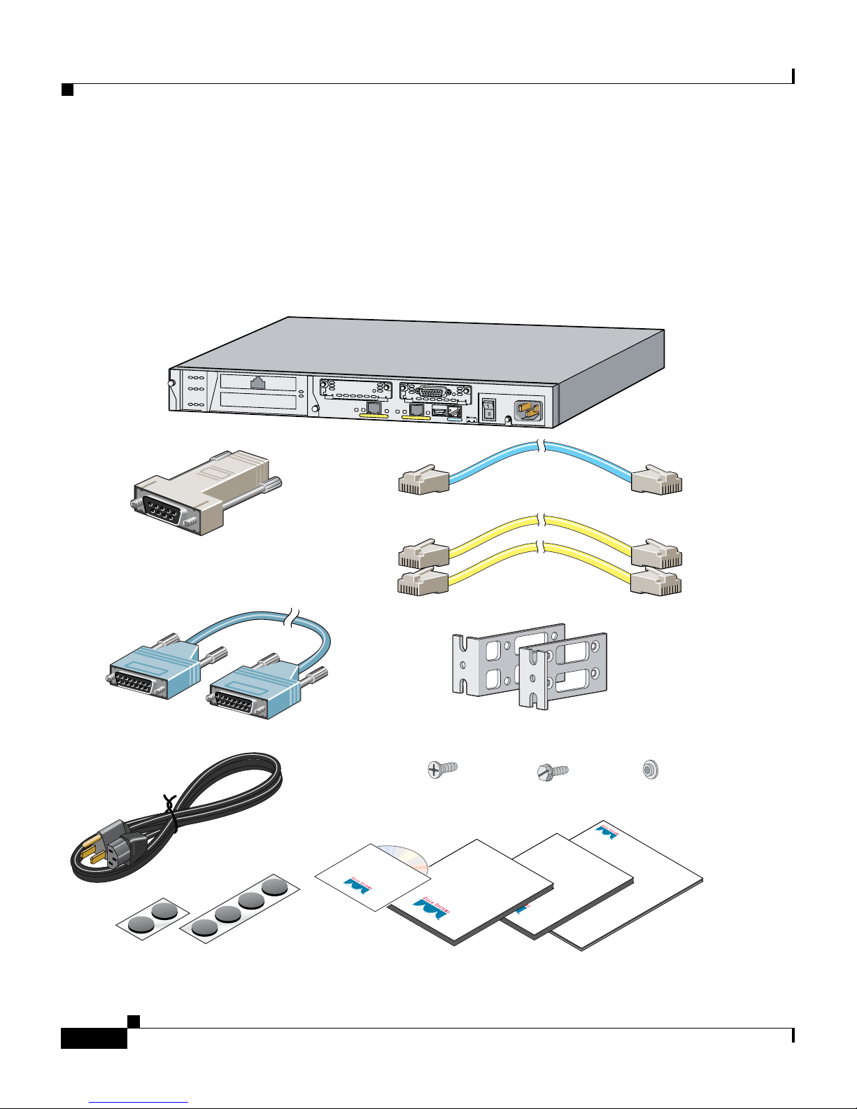
Verify the contents of the packing box, shown in Figure 1-1, to ensure that you
have received all items necessary to install your PIX 515E security appliance.
Figure 1-1 Contents of PIX 515E Package
DO NOT INSTALL INTERFACE
CARDS WITH POWER APPLIED
CONSOLE
PIX-515E
FAILOVER
100 Mbps
Link
FDX
100 Mbps
10/100 ETHERNET 1
PIX 515E
Link
10/100 ETHERNET 0
FDX
PC terminal adapter
(74-0495-01)
Failover serial cable
(74-1213-01)
Power cable
7 flathead screws
(69-0123-01)
Security Appliance
Cisco PIX
Product CD
Blue console cable
(72-1259-01)
Yellow Ethernet cable
(72-1482-01)
Mounting brackets
(700-01170-02 AO SSI-3)
4 cap screws
(69-0124-01)
End User License and
Safety and
Compliance
Guide
Getting Started
Software Warranty
PIX 515E
Guide
4 spacers
(69-0125-01)
Rubber feet
PIX 515E Security Appliance Getting Started Guide
1-2
97955
Documentation
78-17645-01
Page 9
Chapter 1 Installing and Setting Up the PIX 515E Security Appliance
Installing the PIX 515E Security Appliance
Installing the PIX 515E Security Appliance
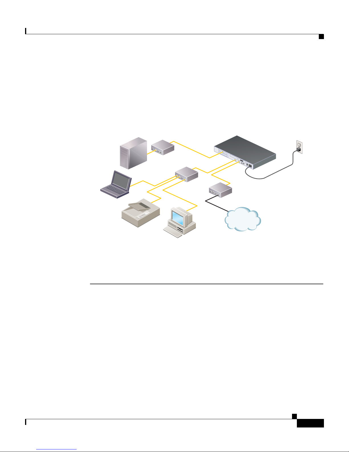
This section describes how to install your PIX 515E security appliance into your
own network, which might resemble the example network in Figure 1-2.
Figure 1-2 Sample Network Layout
PIX 515E
Outside
Router
Internet
Laptop
computer
DMZ server
Printer
Switch
Switch
Personal
computer
DMZ
Inside
To install the PIX 515E security appliance, complete these steps:
Step 1 Mount the chassis in a rack by performing the following steps:
Power
cable
97998
a. Attach the brackets to the chassis with the supplied screws. The brackets
attach to the holes near the front of the chassis.
b. Attach the chassis to the equipment rack.
Step 2 Use one of the provided yellow Ethernet cables to connect the outside 10/100
Ethernet interface, Ethernet 0, to a DSL modem, cable modem, router, or switch.
Step 3 Use the other provided yellow Ethernet cable to connect the inside 10/100
Ethernet interface, Ethernet 1, to a switch or hub.
Step 4 Connect one end of the power cable to the rear of the PIX 515E security appliance
and the other end to a power outlet.
78-17645-01
PIX 515E Security Appliance Getting Started Guide
1-3
Page 10
Chapter 1 Installing and Setting Up the PIX 515E Security Appliance
Front and Back Panel Components
Step 5 Power up the PIX 515E security appliance. The power switch is located at the rear
of the chassis.
Front and Back Panel Components
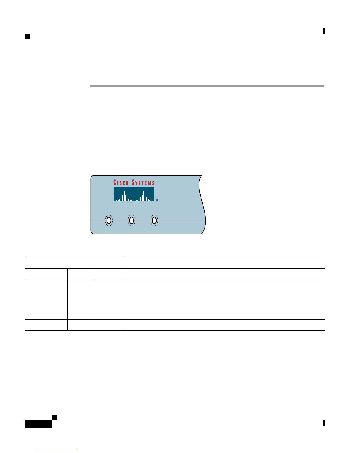
Figure 1-3 illustrates the LEDs on the front panel of the PIX515E Security
Appliance.
Figure 1-3 PIX515E Security Appliance Front Panel LEDs
POWER ACT NETWORK
97779
LED Color State Description
POWER Green On On when the unit has power.
ACT Green On If part of a failover pair, the light is on when the unit is the active
unit.
Off If part of a failover pair, the light is off when the unit is in standby
mode.
NETWORK Green Flashing Flashing when at least one network interface is passing traffic.
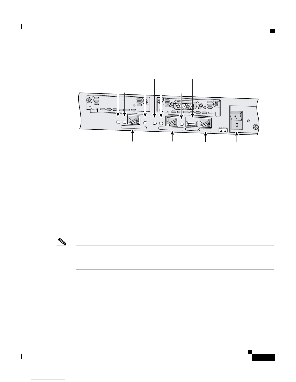
Figure 1-4 illustrates the back panel components.
PIX 515E Security Appliance Getting Started Guide
1-4
78-17645-01
Page 11
Chapter 1 Installing and Setting Up the PIX 515E Security Appliance
Figure 1-4 PIX 515E Security Appliance Back Panel
Setting Up the Security Appliance
100 Mbps
LED
ACT
LED
DO NOT INSTALL INTERFACE
CARDS WITH POWER APPLIED
100 Mbps
ACT
10/100 ETHERNET 1
10/100BaseTX
ETHERNET 1
(RJ-45)
100 Mbps
LED
LINK
LED
LINK
100 Mbps
ACT
LED
ACT
LINK
LED
LINK
10/100BaseTX
ETHERNET 0
(RJ-45)
Setting Up the Security Appliance
This section describes the initial configuration of the security appliance. You can
perform the configuration steps using either the browser-based Cisco Adaptive
Security Device Manager (ASDM) or the command-line interface (CLI).
However, the procedures in this chapter refer to the method using ASDM.
USB
USB
CONSOLE10/100 ETHERNET 0
Console
port (RJ-45)
PIX-515
FAILOVER
Power switch
97784
Note To use ASDM, you must have a DES license or a 3DES-AES license. For more
information, see Appendix A, “Obtaining a DES License or a 3DES-AES
License.”
This section includes the following topics:
• About the Factory-Default Configuration, page 1-6
• About the Adaptive Security Device Manager, page 1-6
• Using the Startup Wizard, page 1-7
78-17645-01
PIX 515E Security Appliance Getting Started Guide
1-5
Page 12
Chapter 1 Installing and Setting Up the PIX 515E Security Appliance
Setting Up the Security Appliance
About the Factory-Default Configuration
Cisco security appliances are shipped with a factory-default configuration that
enables quick startup. The factory-default configuration automatically configures an
interface for management so you can quickly connect to the device and use ASDM to
complete your configuration.
By default, the security appliance management interface is configured with a default
DHCP address pool. This configuration enables a client on the inside network to
obtain a DHCP address from the security appliance to connect to the appliance.
Administrators can then configure and manage the security appliance using ASDM.
About the Adaptive Security Device Manager
PIX 515E Security Appliance Getting Started Guide
1-6
78-17645-01
Page 13

Chapter 1 Installing and Setting Up the PIX 515E Security Appliance
The Adaptive Security Device Manager (ASDM) is a feature-rich graphical
interface that enables you to manage and monitor the security appliance. Its
web-based design provides secure access so that you can connect to and manage
the security appliance from any location by using a web browser.
In addition to its complete configuration and management capability, ASDM
features intelligent wizards to simplify and accelerate the deployment of the
security appliance.
In addition to the ASDM web configuration tool, you can configure the security
appliance by using the command-line interface. For more information, see the
Cisco Security Appliance Command Line Configuration Guide and the Cisco
Security Appliance Command Reference.
Using the Startup Wizard
Setting Up the Security Appliance
ASDM includes a Startup Wizard to simplify the initial configuration of your
security appliance. With a few steps, the Startup Wizard enables you to configure the
security appliance so that it allows packets to flow securely between the inside
network and the outside network.
This section describes how to use the Startup Wizard to set basic configuration
parameters. This section includes the following topics:
• Before Launching the Startup Wizard, page 1-7
• Running the Startup Wizard, page 1-8
Before Launching the Startup Wizard
Before you launch the Startup Wizard, perform the following steps:
Step 1 Obtain a DES license or a 3DES-AES license.
To run ASDM, you must have a DES license or a 3DES-AES license. If you did
not purchase one of these licenses with the security appliance, see Appendix A,
“Obtaining a DES License or a 3DES-AES License” for information about how
to obtain and activate one.
Step 2 Enable Java and Javascript in your web browser.
78-17645-01
PIX 515E Security Appliance Getting Started Guide
1-7
Page 14

Setting Up the Security Appliance
Step 3 Gather the following information:
• A unique hostname to identify the security appliance on your network.
• The IP addresses of your outside interface, inside interface, and any other
interfaces to be configured.
• The IP addresses to use for Network Address Translation (NAT) or Port
Address Translation (PAT) configuration.
• The IP address range for the DHCP server.
Running the Startup Wizard
To use the Startup Wizard to set up a basic configuration for the security appliance,
perform the following steps:
Chapter 1 Installing and Setting Up the PIX 515E Security Appliance
Step 1 Use an Ethernet cable to connect your PC to the inside port (Ethernet 1) on the
rear panel of the PIX 515E.
Step 2 Configure your PC to use DHCP (to receive an IP address automatically from the
PIX 515E).
Alternatively, you can assign a static IP address to your PC. If you use a static IP
address, use any address from the 192.168.1.0 range except 192.168.1.1. This IP
address is assigned to the inside interface of the PIX 515E.
Step 3 Start ASDM.
a. On the PC connected to the inside port of the PIX 515E, start an Internet
browser.
b. In the address field of the browser, enter this URL:
https://192.168.1.1/admin.
Note The security appliance ships with a default IP address of 192.168.1.1.
Remember to add the “s” in “https” or the connection fails. HTTPS
(HTTP over SSL) provides a secure connection between your
browser and the security appliance.
PIX 515E Security Appliance Getting Started Guide
1-8
78-17645-01
Page 15

Chapter 1 Installing and Setting Up the PIX 515E Security Appliance
c. In the window that requires you to choose the method you want to use to run
the ASDM software, choose either to download the ASDM launcher or to run
the ASDM software as a Java applet.
Step 4 In the dialog box that requires a username and password, leave both fields empty.
Press Enter.
Step 5 Click Yes to accept the certificates. Click Yes for all subsequent authentication
and certificate dialog boxes.
ASDM starts.
Step 6 From the Wizards menu, choose Startup Wizard.
Step 7 Follow the instructions in the Startup Wizard to set up your security appliance.
For information about any field in the Startup Wizard, click Help at the bottom
of the window.
What to Do Next
Note Based on your network security policy, you should also consider configuring the
security appliance to deny all ICMP traffic through the outside interface or any
other interface that is necessary. You can configure this access control policy
using the icmp command. For more information about the icmp command, see the
Cisco Security Appliance Command Reference.
What to Do Next
Next, configure the security appliance for your deployment using one or more of
the following chapters:
To Do This ... See ...
Configure the security appliance to
protect a DMZ web server
Configure the security appliance for
remote-access VPN
Configure the security appliance for
Site-to-Site VPN
Chapter 2, “Scenario: DMZ
Configuration”
Chapter 3, “Scenario: IPsec
Remote-Access VPN Configuration”
Chapter 4, “Scenario: Site-to-Site
VPN Configuration”
78-17645-01
PIX 515E Security Appliance Getting Started Guide
1-9
Page 16

What to Do Next
Chapter 1 Installing and Setting Up the PIX 515E Security Appliance
PIX 515E Security Appliance Getting Started Guide
1-10
78-17645-01
Page 17

CHAPTER
2
Scenario: DMZ Configuration
This chapter describes a configuration scenario in which the security appliance is
used to protect network resources located in a demilitarized zone (DMZ). A DMZ
is a separate network located in the neutral zone between a private (inside)
network and a public (outside) network.
This chapter includes the following sections:
• Example DMZ Network Topology, page 2-1
• Configuring the Security Appliance for a DMZ Deployment, page 2-4
• What to Do Next, page 2-24
Example DMZ Network Topology
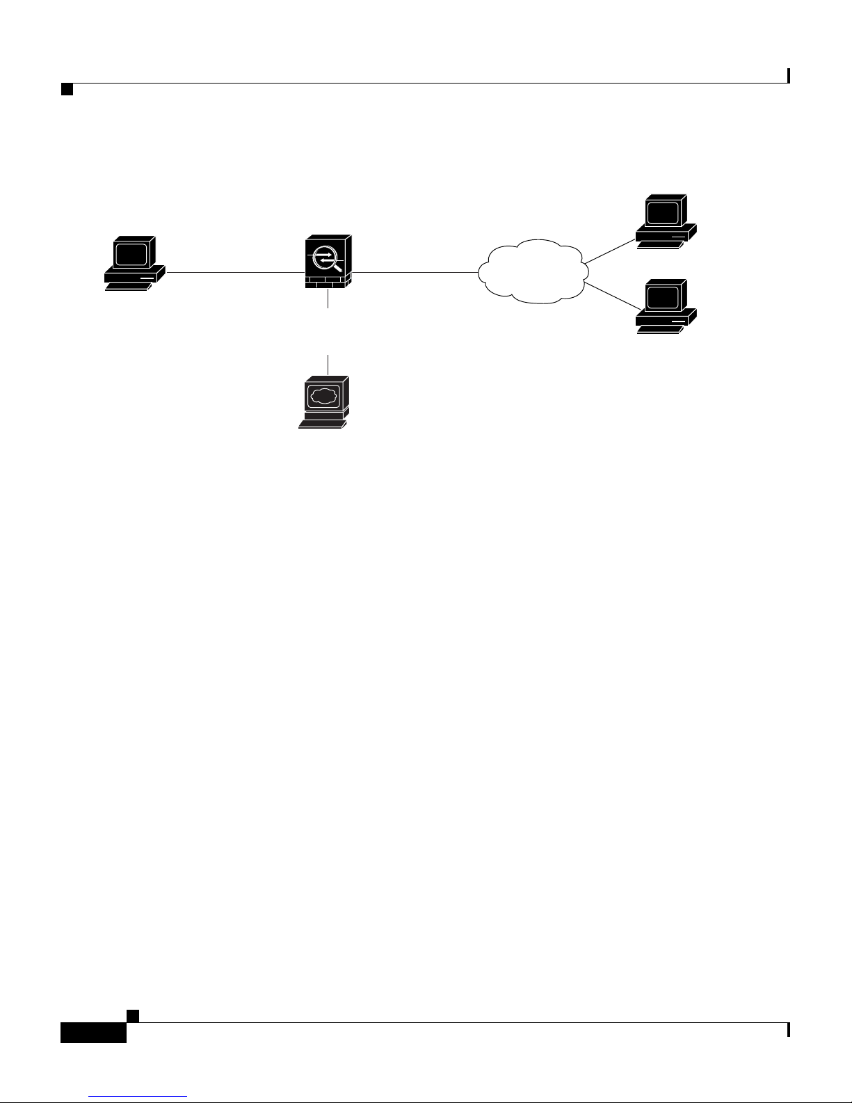
The example network topology shown in Figure 2-1 is typical of most DMZ
implementations of the security appliance.
PIX 515E Security Appliance Getting Started Guide
78-17645-01
2-1
Page 18
Example DMZ Network Topology
Figure 2-1 Network Layout for DMZ Configuration Scenario
Security
HTTP client
inside interface
10.10.10.0
(private address)
Appliance
outside interface
209.165.200.225
(public address)
Internet
10.10.10.0
(private address)
DMZ interface
10.30.30.0
(private address)
Chapter 2 Scenario: DMZ Configuration
HTTP client
HTTP client
DMZ Web
Server
Private IP address: 10.30.30.30
Public IP address: 209.165.200.226
132064
This example scenario has the following characteristics:
• The web server is on the DMZ interface of the security appliance.
• HTTP clients on the private network can access the web server in the DMZ
and can also communicate with devices on the Internet.
• Clients on the Internet are permitted HTTP access to the DMZ web server; all
other traffic is denied.
• The network has two routable IP addresses that are publicly available: one for
the outside interface of the security appliance (209.165.200.225), and one for
the public IP address of the DMZ web server (209.165.200.226).
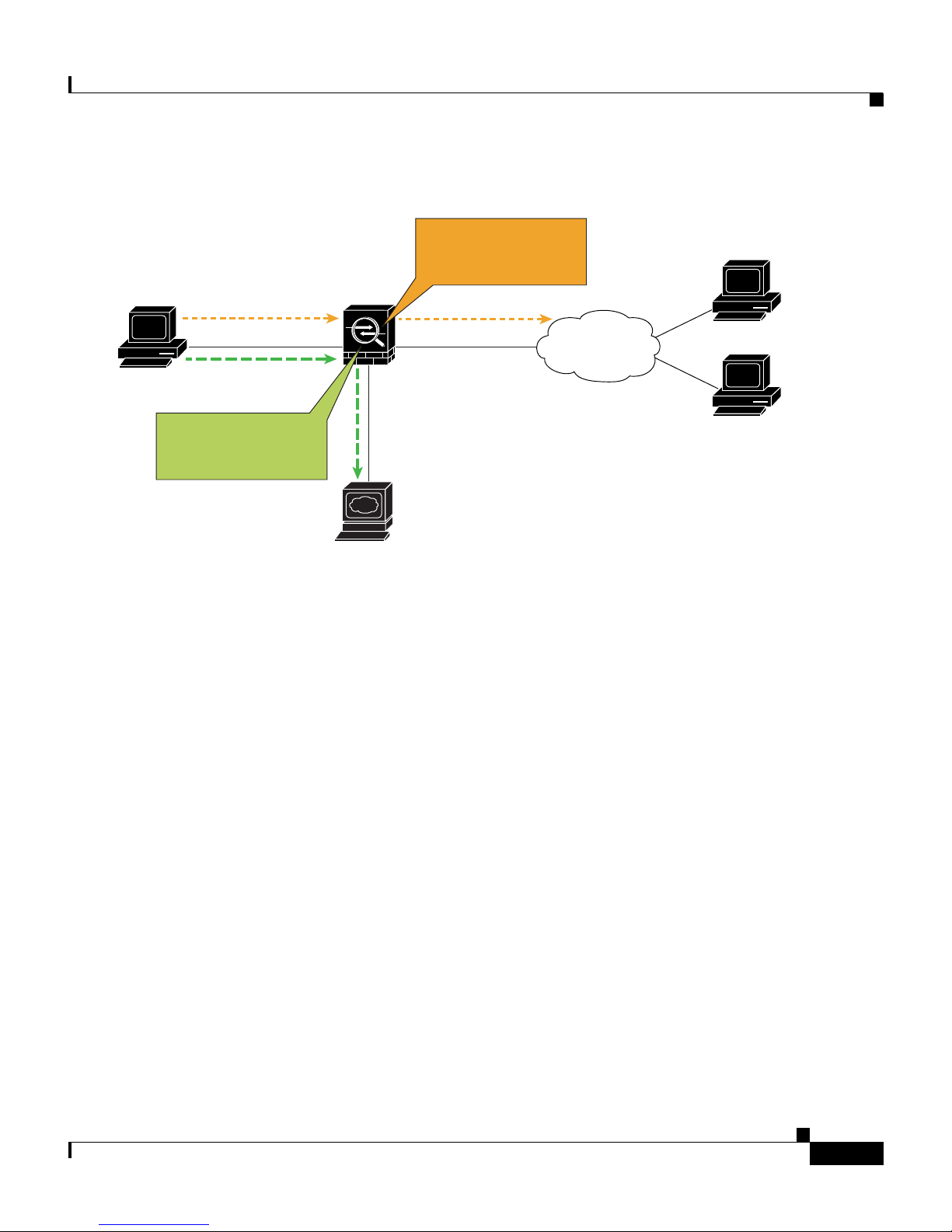
Figure 2-2 shows the outgoing traffic flow of HTTP requests from the private
network to both the DMZ web server and to the Internet.
PIX 515E Security Appliance Getting Started Guide
2-2
78-17645-01
Page 19
Chapter 2 Scenario: DMZ Configuration
Figure 2-2 Outgoing HTTP Traffic Flow from the Private Network
Internal IP address
translated to address
of outside interface
HTTP client
Security
Appliance
Example DMZ Network Topology
10.10.10.0
(private address)
Internal IP address
translated to address
HTTP request
HTTP request
from IP pool
DMZ network
In Figure 2-2, the security appliance permits HTTP traffic originating from inside
clients and destined for both the DMZ web server and devices on the Internet. To
permit the traffic through, the security appliance configuration includes the
following:
DMZ Web
Server
outside interface
209.165.200.225
(public address)
Private IP address: 10.30.30.30
Public IP address: 209.165.200.226
Internet
HTTP client
HTTP client
153777
• Access control rules permitting traffic destined for the DMZ web server and
for devices on the Internet.
• Address translation rules translating private IP addresses so that the private
addresses are not visible to the Internet.
For traffic destined for the DMZ web server, private IP addresses are
translated to an address from an IP pool.
For traffic destined for the Internet, private IP addresses are translated to the
public IP address of the security appliance. Outgoing traffic appears to come
from this address.
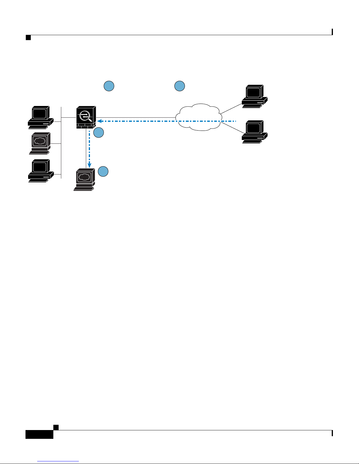
Figure 2-3 shows HTTP requests originating from the Internet and destined for
the public IP address of the DMZ web server.
78-17645-01
PIX 515E Security Appliance Getting Started Guide
2-3
Page 20
Configuring the Security Appliance for a DMZ Deployment
Figure 2-3 Incoming HTTP Traffic Flow From the Internet
HTTP request
1
sent to public address
of DMZ web server.
Internet
Security
Appliance
2
Incoming request
destined for public
address of DMZ web
server intercepted.
3
Destination IP address
translated to the private IP
address of the web server.
4
Web server receives
request for content.
Chapter 2 Scenario: DMZ Configuration
HTTP client
HTTP client
DMZ Web
Server
Private IP address: 10.30.30.30
Public IP address: 209.165.200.226
153779
To permit incoming traffic to access the DMZ web server, the security appliance
configuration includes the following:
• An address translation rule translating the public IP address of the DMZ web
server to the private IP address of the DMZ web server.
• An access control rule permitting incoming HTTP traffic that is destined for
the DMZ web server.
The procedures for creating this configuration are detailed in the remainder of this
chapter.
Configuring the Security Appliance for a DMZ
Deployment
This section describes how to use ASDM to configure the security appliance for
the configuration scenario shown in Figure 2-1. The procedure uses sample
parameters based on the scenario.
PIX 515E Security Appliance Getting Started Guide
2-4
78-17645-01
Page 21

Chapter 2 Scenario: DMZ Configuration
This configuration procedure assumes that the security appliance already has
interfaces configured for the inside interface, the DMZ interface, and the outside
interface. Set up interfaces of the security appliance by using the Startup Wizard
in ASDM. Be sure that the DMZ interface security level is set between 0 and 100.
(A common choice is 50.)
For more information about using the Startup Wizard, see Setting Up the Security
Appliance, page 1-5.
The section includes the following topics:
• Configuration Requirements, page 2-5
• Starting ASDM, page 2-6
• Creating IP Pools for Network Address Translation, page 2-7
• Configuring NAT for Inside Clients to Communicate with the DMZ Web
Server, page 2-12
Configuring the Security Appliance for a DMZ Deployment
• Configuring an External Identity for the DMZ Web Server, page 2-16
• Providing Public HTTP Access to the DMZ Web Server, page 2-18
The following sections provide detailed instructions for how to perform each step.
Configuration Requirements
Configuring the security appliance for this DMZ deployment requires the
following configuration tasks:
• For the internal clients to have HTTP access to the DMZ web server, you
must create a pool of IP addresses for address translation and identify which
clients should use addresses from the pool. To accomplish this task, you
should configure the following:
–
A pool of IP addresses for the DMZ interface. In this scenario, the IP pool
is 10.30.30.50–10.30.30.60.
–
A dynamic NAT translation rule for the inside interface that specifies
which client IP addresses can be assigned an address from the IP pool.
• For the internal clients to have access to HTTP and HTTPS resources on the
Internet, you must create a rule that translates the real IP addresses of internal
clients to an external address that can be used as the source address.
78-17645-01
PIX 515E Security Appliance Getting Started Guide
2-5
Page 22

Configuring the Security Appliance for a DMZ Deployment
To accomplish this task, you should configure a PAT translation rule (port
address translation rule, sometimes called an interface NAT) for the internal
interface that translates internal IP addresses to the external IP address of the
security appliance.
In this scenario, the internal address to be translated is that of a subnet of the
private network (10.10.10.0). Addresses from this subnet are translated to the
public address of the security appliance (209.165.200.225).
• For external clients to have HTTP access to the DMZ web server, you must
configure an external identity for the DMZ web server and an access rule that
permits HTTP requests coming from clients on the Internet. To accomplish
this task, you should configure the following:
–
Create a static NAT rule. This rule translates the real IP address of the
DMZ web server to a single public IP address. In this scenario, the public
address of the web server is 209.165.200.226.
Chapter 2 Scenario: DMZ Configuration
Starting ASDM
To run ASDM in a web browser, enter the factory-default IP address in the
address field: https://192.168.1.1/admin/.
Note Remember to add the “s” in “https” or the connection fails. HTTPS
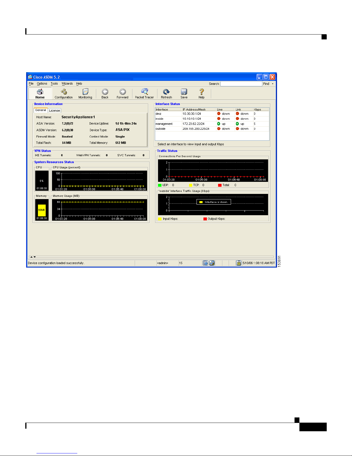
The Main ASDM window appears.
–
Create a security access rule permitting traffic from the Internet if the
traffic is an HTTP request destined for the public IP address of the DMZ
web server.
(HTTP over SSL) provides a secure connection between your browser
and the security appliance.
PIX 515E Security Appliance Getting Started Guide
2-6
78-17645-01
Page 23
Chapter 2 Scenario: DMZ Configuration
Configuring the Security Appliance for a DMZ Deployment
Creating IP Pools for Network Address Translation
The security appliance uses Network Address Translation (NAT) and Port
Address Translation (PAT) to prevent internal IP addresses from being exposed
externally. This procedure describes how to create a pool of IP addresses that the
DMZ interface and outside interface can use for address translation.
A single IP pool can contain both NAT and PAT entries, and it can contain entries
for more than one interface.
78-17645-01
PIX 515E Security Appliance Getting Started Guide
2-7
Page 24
Configuring the Security Appliance for a DMZ Deployment
To configure a pool of IP addresses that can be used for network address
translation, perform the following steps:
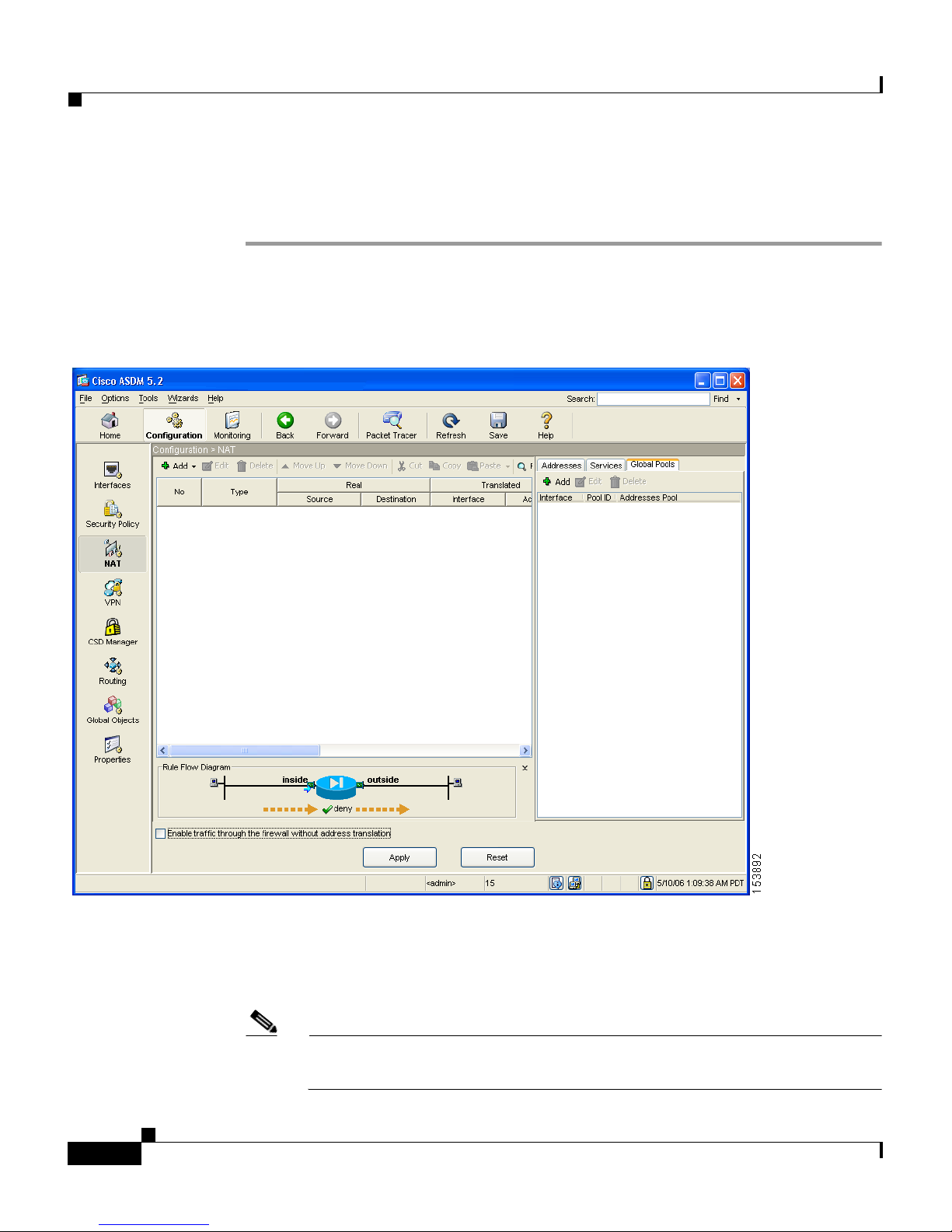
Step 1 In the ASDM window, click the Configuration tool.
a. In the Features pane, click NAT.
The NAT Configuration screen appears.
Chapter 2 Scenario: DMZ Configuration
b. In the right pane, click the Global Pools tab.
c. Click Add to create a new global pool for the DMZ interface.
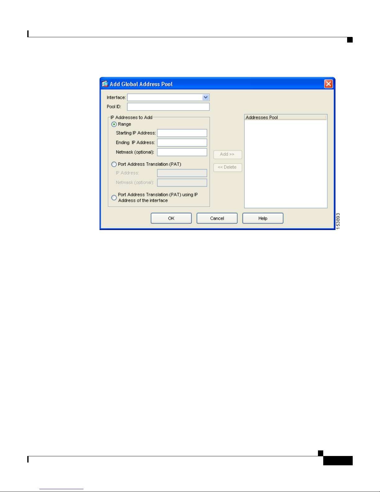
The Add Global Address Pool dialog box appears.
Note For most configurations, IP pools are added to the less secure, or public,
interfaces.
PIX 515E Security Appliance Getting Started Guide
2-8
78-17645-01
Page 25
Chapter 2 Scenario: DMZ Configuration
Configuring the Security Appliance for a DMZ Deployment
d. From the Interfaces drop-down list, choose DMZ.
e. To create a new IP pool, enter a unique Pool ID. In this scenario, the Pool ID
is 200.
f. In the IP Addresses to Add area, specify the range of IP addresses to be used
by the DMZ interface:
–
Click the Range radio button.
–
Enter the Starting IP address and Ending IP address of the range. In this
scenario, the range of IP addresses is 10.30.30.50–10.30.30.60.
–
(Optional) Enter the Netmask for the range of IP addresses.
78-17645-01
PIX 515E Security Appliance Getting Started Guide
2-9
Page 26
Configuring the Security Appliance for a DMZ Deployment
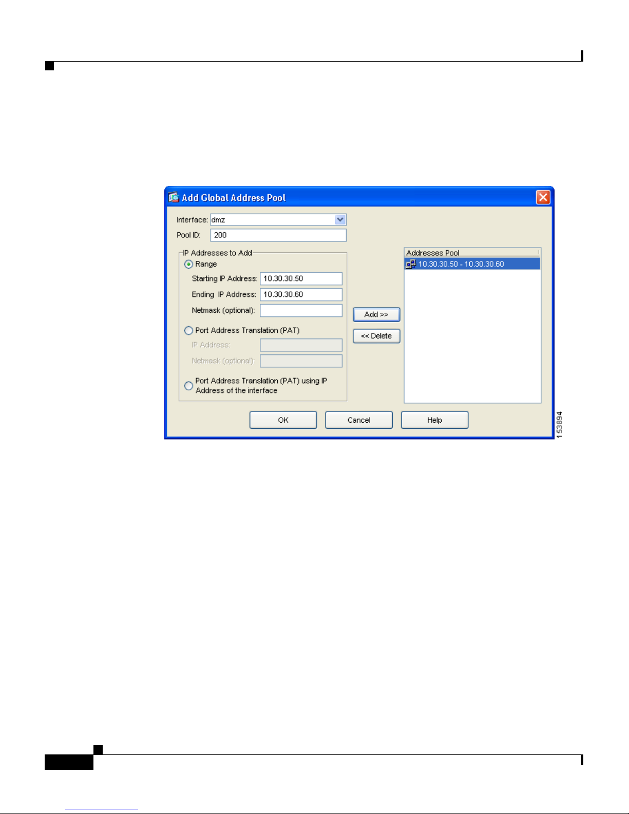
g. Click Add to add this range of IP addresses to the Address Pool.
The Add Global Pool dialog box configuration should be similar to the
following:
Chapter 2 Scenario: DMZ Configuration
2-10
h. Click OK to return to the Configuration > NAT window.
Step 2 Add addresses to the IP pool to be used by the outside interface. These addresses
are used to translate private IP addresses so that inside clients can communicate
securely with clients on the Internet.
In this scenario, there are limited public IP addresses available. Use Port Address
Translation (PAT) so that many internal IP addresses can map to the same public
IP address, as follows:
a. In the right pane of the NAT Configuration screen, click the Global Pools
tab.
b. Under the Global Pools tab, click Add.
The Add Global Pool Item dialog box appears.
c. From the Interface drop-down list, choose Outside.
d. Specify a Pool ID for the Outside interface.
PIX 515E Security Appliance Getting Started Guide
78-17645-01
Page 27
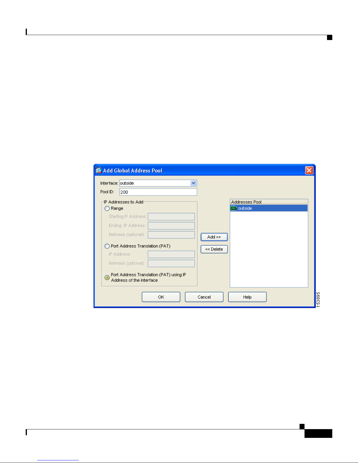
Chapter 2 Scenario: DMZ Configuration
You can add these addresses to the same IP pool that contains the address
pool used by the DMZ interface (in this scenario, the Pool ID is 200).
e. Click the Port Address Translation (PAT) using the IP address of the
interface radio button.
If you select the option Port Address Translation using the IP address of the
interface, all traffic initiated from the inside network exits the security
appliance using the IP address of the outside interface. To the devices on the
Internet, it appears that all traffic is coming from this one IP address.
f. Click the Add button to add this new address to the IP pool.
Configuring the Security Appliance for a DMZ Deployment
g. Click OK.
78-17645-01
PIX 515E Security Appliance Getting Started Guide
2-11
Page 28
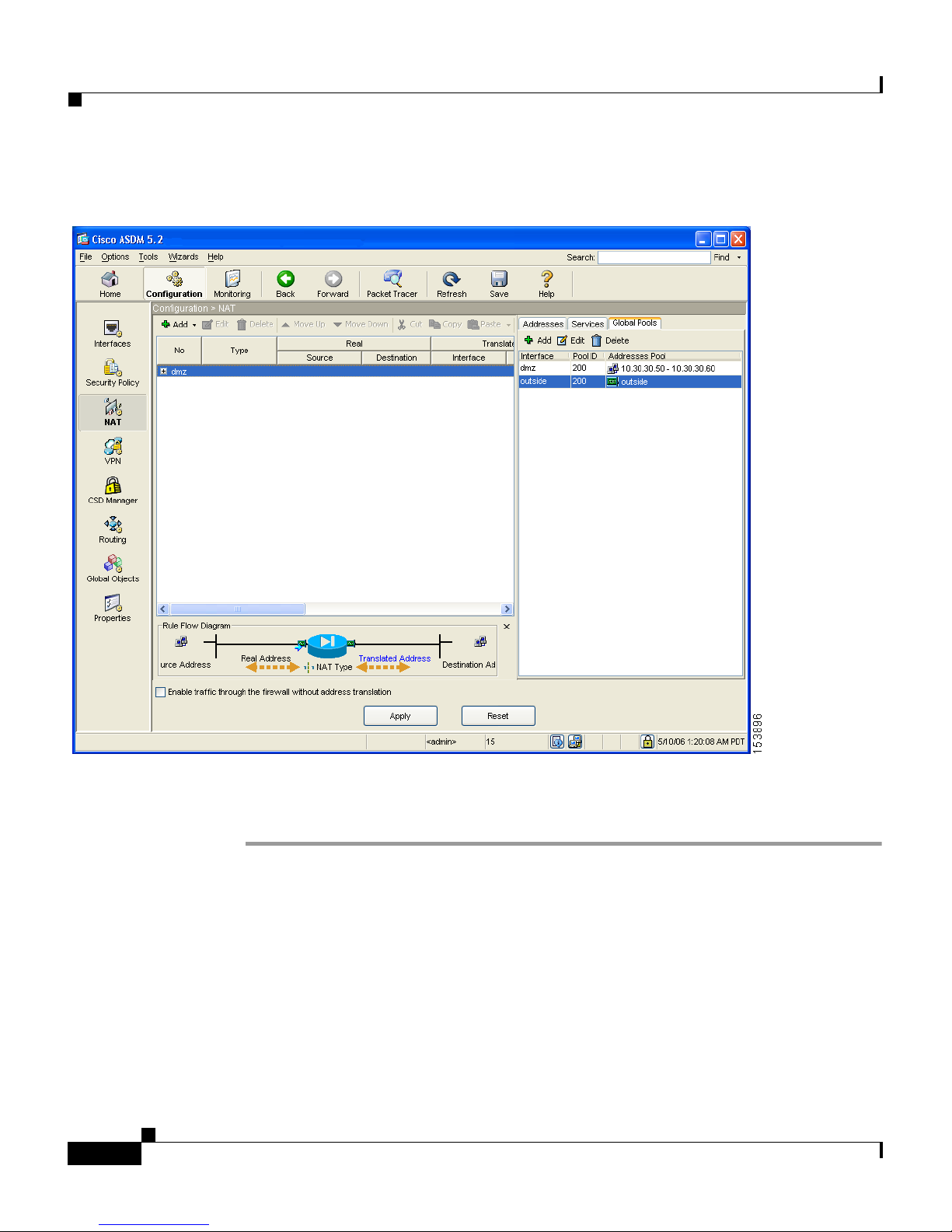
Configuring the Security Appliance for a DMZ Deployment
The displayed configuration should be similar to the following:
Chapter 2 Scenario: DMZ Configuration
Step 3 Confirm that the configuration values are correct.
Step 4 Click Apply in the main ASDM window.
Configuring NAT for Inside Clients to Communicate with the DMZ
Web Server
In the previous procedure, you created a pool of IP addresses that could be used
by the security appliance to mask the private IP addresses of inside clients.
PIX 515E Security Appliance Getting Started Guide
2-12
78-17645-01
Page 29

Chapter 2 Scenario: DMZ Configuration
In this procedure, you configure a Network Address Translation (NAT) rule that
associates IP addresses from this pool with the inside clients so they can
communicate securely with the DMZ web server.
To configure NAT between the inside interface and the DMZ interface, perform
the following steps starting from the main ASDM window:
Step 1 In the main ASDM window, click the Configuration tool.
Step 2 In the Features pane, click NAT.
Step 3 From the Add drop-down list, choose Add Dynamic NAT Rule.
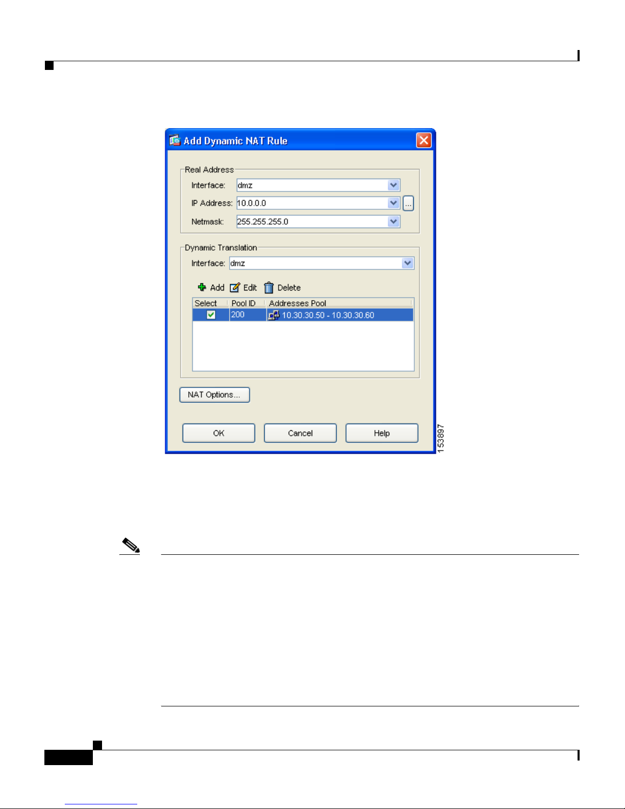
The Add Dynamic NAT Rule dialog box appears.
Step 4 In the Real Address area, specify the IP address to be translated. For this scenario,
address translation for inside clients is done according to the IP address of the
subnet.
Configuring the Security Appliance for a DMZ Deployment
a. From the Interface drop-down list, choose the Inside interface.
b. Enter the IP address of the client or network. In this scenario, the IP address
of the network is 10.10.10.0.
c. From the Netmask drop-down list, choose the Netmask. In this scenario, the
netmask is 255.255.255.0.
Step 5 In the Dynamic Translation area:
a. From the Interface drop-down list, choose the DMZ interface.
b. To specify the address pool to be used for this Dynamic NAT rule, check the
Select check box next to Global Pool ID. In this scenario, the IP pool ID is
200.
In this scenario, the IP pool that we want to use is already created. If it was
not already created, you would click Add to create a new IP pool.
78-17645-01
PIX 515E Security Appliance Getting Started Guide
2-13
Page 30
Configuring the Security Appliance for a DMZ Deployment
Chapter 2 Scenario: DMZ Configuration
2-14
c. Click OK to add the Dynamic NAT Rule and return to the Configuration >
NAT window.
Review the configuration screen to verify that the translation rule appears as you
expected.
Note When you click OK to create this rule, notice that there are actually two
translation rules created:
• A translation rule between the inside and DMZ interfaces to be used when
inside clients communicate with the DMZ web server.
• A translation rule between the inside and outside interfaces to be used when
inside clients communicate with the Internet.
ASDM is able to create both rules because the addresses to be used for translation
are both in the same IP pool.
PIX 515E Security Appliance Getting Started Guide
78-17645-01
Page 31
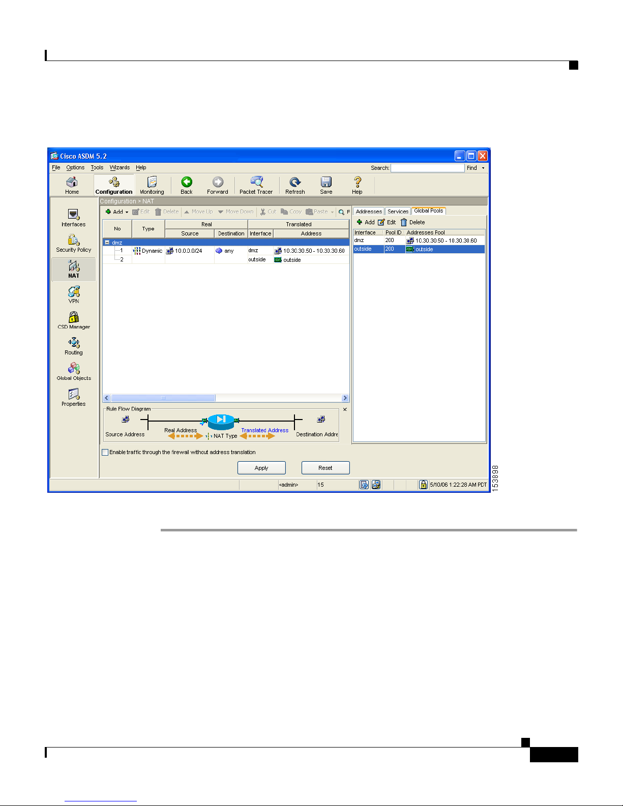
Chapter 2 Scenario: DMZ Configuration
The displayed configuration should be similar to the following:
Configuring the Security Appliance for a DMZ Deployment
Step 6 Click Apply to complete the security appliance configuration changes.
Configuring NAT for Inside Clients to Communicate with Devices
on the Internet
In the previous procedure, you configured a Network Address Translation (NAT)
rule that associates IP addresses from the IP pool with the inside clients so they
can communicate securely with the DMZ web server.
78-17645-01
PIX 515E Security Appliance Getting Started Guide
2-15
Page 32

Chapter 2 Scenario: DMZ Configuration
Configuring the Security Appliance for a DMZ Deployment
For many configurations, you would also need to create a NAT rule between the
inside interface and the outside interface to enable inside clients to communicate
with the Internet.
However, in this scenario you do not need to create this rule explicitly. The reason
is that the IP pool (pool ID 200) contains both types of addresses needed for
address translation: the range of IP addresses to be used by the DMZ interface,
and the IP address to be used for the outside interface. This enables ASDM to
create the second translation rule for you.
Configuring an External Identity for the DMZ Web Server
The DMZ web server needs to be accessible by all hosts on the Internet. This
configuration requires translating the private IP address of the DMZ web server
to a public IP address, enabling access to outside HTTP clients that are unaware
of the security appliance. To map the real web server IP address (10.30.30.30)
statically to a public IP address (209.165.200.226), perform the following steps:
Step 1 In the ASDM window, click the Configuration tool.
Step 2 In the Features pane, click NAT.
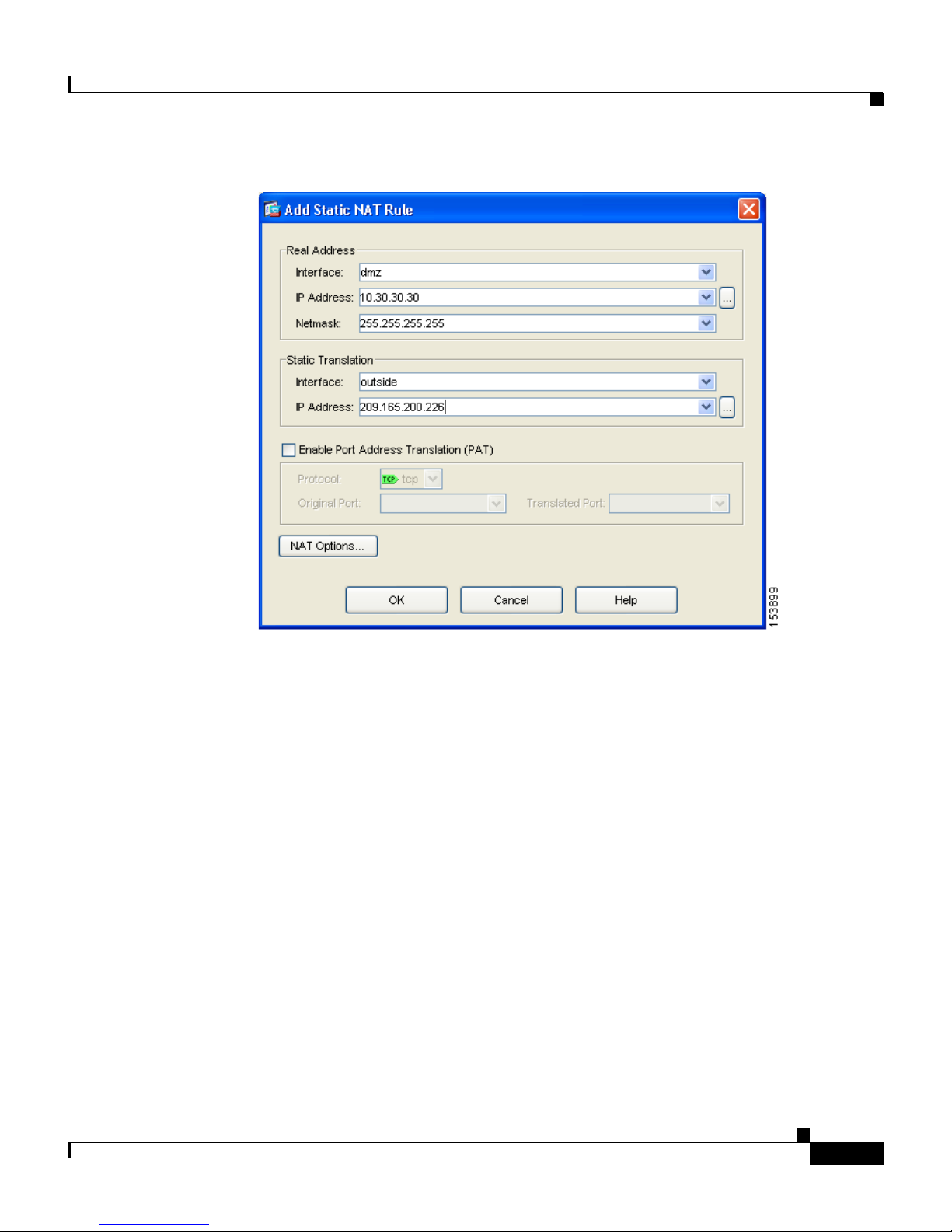
Step 3 From the Add drop-down list, choose Add Static NAT Rule. The Add Static NAT
Rule dialog box appears.
Step 4 In the Real Address area, specify the real IP address of the web server:
a. From the Interface drop-down list, choose the DMZ interface.
b. Enter the real IP address of the DMZ web server. In this scenario, the IP
address is 10.30.30.30.
c. From the Netmask drop-down list, choose the Netmask 255.255.255.255.
PIX 515E Security Appliance Getting Started Guide
2-16
78-17645-01
Page 33
Chapter 2 Scenario: DMZ Configuration
Configuring the Security Appliance for a DMZ Deployment
Step 5 In the Static Translation area, specify the public IP address to be used for the web
server:
a. From the Interface drop-down list, choose Outside.
b. From the IP Address drop-down list, choose the public IP address of the DMZ
web server.
In this scenario, the public IP address of the DMZ web server is
209.165.200.226.
Step 6 Click OK to add the rule and return to the list of Address Translation Rules.
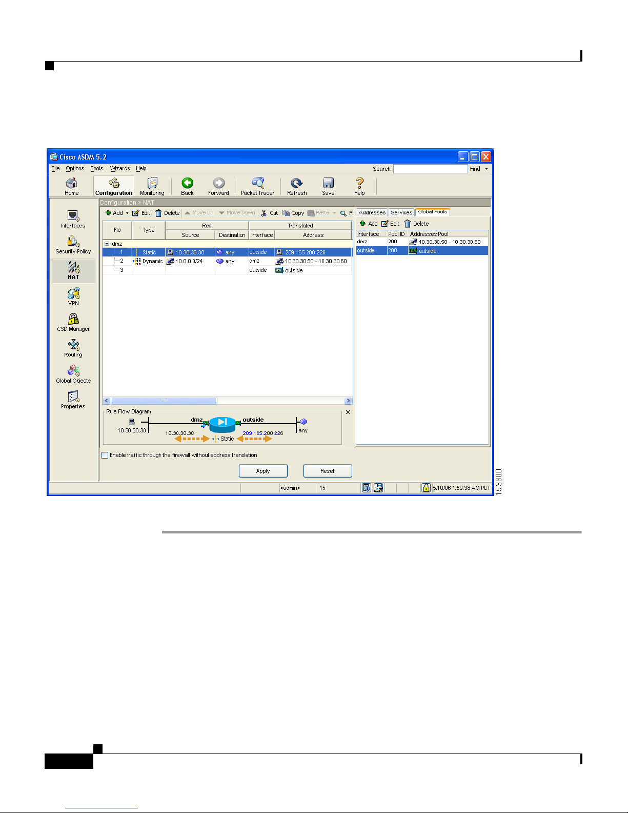
This rule maps the real web server IP address (10.30.30.30) statically to the public
IP address of the web server (209.165.200.226).
78-17645-01
PIX 515E Security Appliance Getting Started Guide
2-17
Page 34
Configuring the Security Appliance for a DMZ Deployment
The displayed configuration should be similar to the following:
Chapter 2 Scenario: DMZ Configuration
Step 7 Click Apply to complete the security appliance configuration changes.
Providing Public HTTP Access to the DMZ Web Server
By default, the security appliance denies all traffic coming in from the public
network. You must create an access control rule on the security appliance to
permit specific traffic types from the public network to resources in the DMZ.
This access control rule specifies the interface of the security appliance that
PIX 515E Security Appliance Getting Started Guide
2-18
78-17645-01
Page 35

Chapter 2 Scenario: DMZ Configuration
processes the traffic, whether the traffic is incoming or outgoing, the origin and
destination of the traffic, and the type of traffic protocol and service to be
permitted.
In this section, you create an access rule that permits incoming HTTP traffic
originating from any host or network on the Internet, if the destination of the
traffic is the web server on the DMZ network. All other traffic coming in from the
public network is denied.
To configure the access control rule, perform the following steps:
Step 1 In the ASDM window:
a. Click the Configuration tool.
b. In the Features pane, click Security Policy.
c. Click the Access Rules tab, and then from the Add pull-down list, choose
Add Access Rule.
Configuring the Security Appliance for a DMZ Deployment
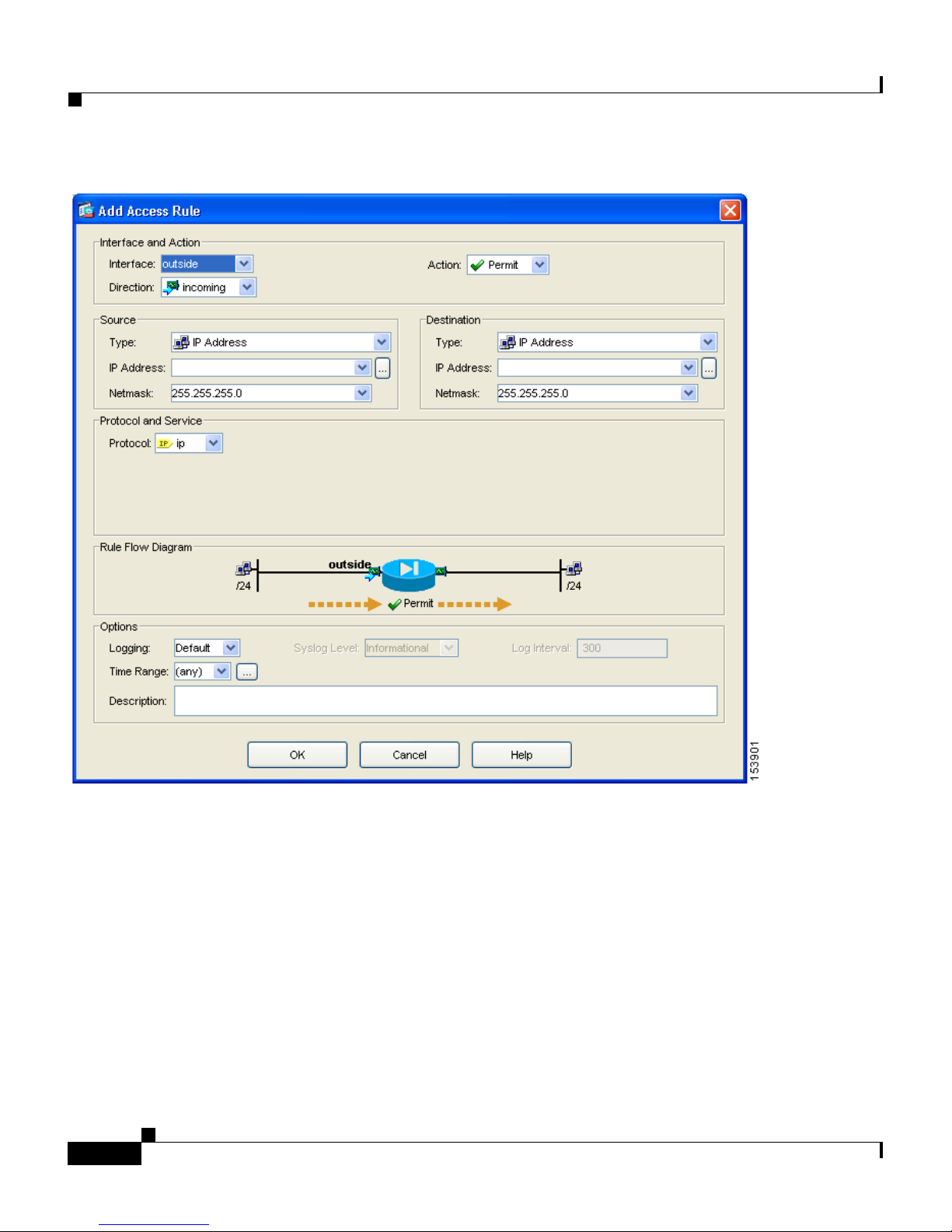
The Add Access Rule dialog box appears.
78-17645-01
PIX 515E Security Appliance Getting Started Guide
2-19
Page 36
Configuring the Security Appliance for a DMZ Deployment
Chapter 2 Scenario: DMZ Configuration
Step 2 In the Interface and Action area:
a. From the Interface drop-down list, choose Outside.
b. From the Direction drop-down list, choose Incoming.
c. From the Action drop-down list, choose Permit.
Step 3 In the Source area:
a. From the Type drop-down list, choose IP Address.
b. Enter the IP address of the source host or source network. Use 0.0.0.0 to allow
traffic originating from any host or network.
PIX 515E Security Appliance Getting Started Guide
2-20
78-17645-01
Page 37

Chapter 2 Scenario: DMZ Configuration
Alternatively, if the address of the source host or network is preconfigured,
choose the source IP address from the IP Address drop-down list.
c. Enter the netmask for the source IP address or select one from the Netmask
drop-down list.
Step 4 In the Destination area:
a. In the IP address field, enter the public IP address of the destination host or
network, such as a web server. (In this scenario, the public IP address of the
DMZ web server is 209.165.200.226.)
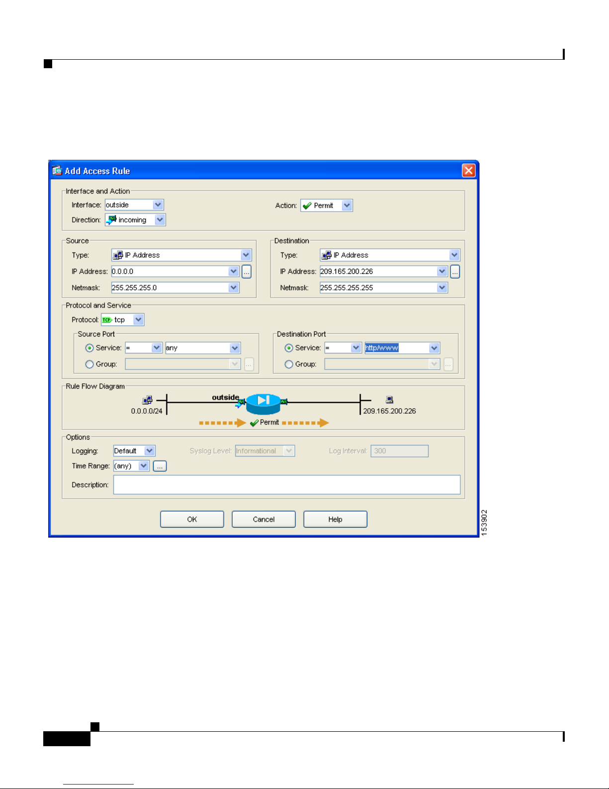
Step 5 In the Protocol and Service area, specify the type of traffic that you want to permit
through the security appliance.
a. From the Protocol drop-down list, choose tcp.
b. In the Source Port area, click the Service radio button, choose “=” (equal to)
from the Service drop-down list, and then choose Any from the next
drop-down list.
Configuring the Security Appliance for a DMZ Deployment
c. In the Destination Port area, click the Service radio button, choose “=” (equal
to) from the Service drop-down list, and then choose HTTP/WWW from the
next drop-down list.
78-17645-01
PIX 515E Security Appliance Getting Started Guide
2-21
Page 38
Configuring the Security Appliance for a DMZ Deployment
At this point, the entries in the Add Access Rule dialog box should be similar to
the following:
Chapter 2 Scenario: DMZ Configuration
d. Click OK.
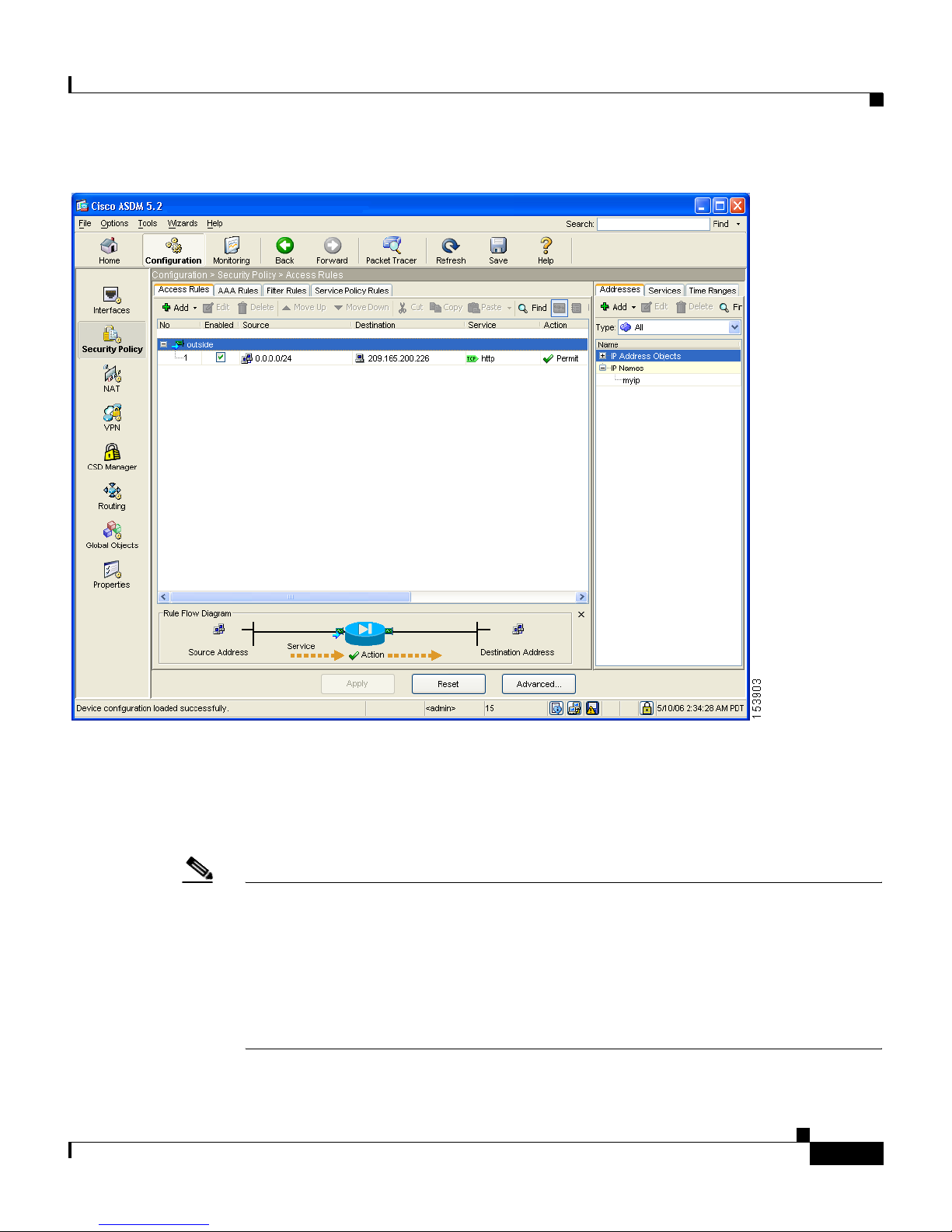
Step 6 The displayed configuration should be similar to the following. Verify that the
information you entered is accurate.
PIX 515E Security Appliance Getting Started Guide
2-22
78-17645-01
Page 39
Chapter 2 Scenario: DMZ Configuration
Configuring the Security Appliance for a DMZ Deployment
78-17645-01
Step 7 Click Apply to save the configuration changes to the configuration that the
security appliance is currently running.
Clients on both the private and public networks can now resolve HTTP requests
for content from the DMZ web server, while keeping the private network secure.
Note Although the destination address specified is the private address of the DMZ web
server (10.30.30.30), HTTP traffic from any host on the Internet destined for the
public address 209.165.200.226 is permitted through the security appliance. The
address translation (209.165.200.226 to 10.30.30.30) allows the traffic to be
permitted. For information about creating the translation rule, see the
“Configuring NAT for Inside Clients to Communicate with the DMZ Web
Server” section on page 2-12.
PIX 515E Security Appliance Getting Started Guide
2-23
Page 40

What to Do Next
Step 8 If you want the configuration changes to be saved to the startup configuration so
that they are applied the next time the device starts, from the File menu, click
Save.
Alternatively, ASDM prompts you to save the configuration changes permanently
when you exit ASDM.
If you do not save the configuration changes, the old configuration takes effect
the next time the device starts.
What to Do Next
If you are deploying the security appliance solely to protect a web server in a
DMZ, you have completed the initial configuration.
Chapter 2 Scenario: DMZ Configuration
You may want to consider performing some of the following additional steps:
To Do This ... See ...
Refine configuration and configure
optional and advanced features
Cisco Security Appliance Command
Line Configuration Guide
Learn about daily operations Cisco Security Appliance Command
Reference
Cisco Security Appliance Logging
Configuration and System Log
Messages
You can configure the security appliance for more than one application. The
following sections provide configuration procedures for other common
applications of the security appliance.
PIX 515E Security Appliance Getting Started Guide
2-24
78-17645-01
Page 41

Chapter 2 Scenario: DMZ Configuration
To Do This ... See ...
Configure a remote-access VPN Chapter 3, “Scenario: IPsec
Configure a site-to-site VPN Chapter 4, “Scenario: Site-to-Site
What to Do Next
Remote-Access VPN Configuration”
VPN Configuration”
78-17645-01
PIX 515E Security Appliance Getting Started Guide
2-25
Page 42

What to Do Next
Chapter 2 Scenario: DMZ Configuration
PIX 515E Security Appliance Getting Started Guide
2-26
78-17645-01
Page 43

CHAPTER
3
Scenario: IPsec Remote-Access VPN
Configuration
This chapter describes how to use the security appliance to accept remote-access
IPsec VPN connections. A remote-access VPN enables you to create secure
connections, or tunnels, across the Internet, thus providing secure access to
off-site users.
If you are implementing an Easy VPN solution, this chapter describes how to
configure the Easy VPN server (sometimes called a headend device).
This chapter includes the following sections:
• Example IPsec Remote-Access VPN Network Topology, page 3-1
• Implementing the IPsec Remote-Access VPN Scenario, page 3-2
• What to Do Next, page 3-18
Example IPsec Remote-Access VPN Network
Topology
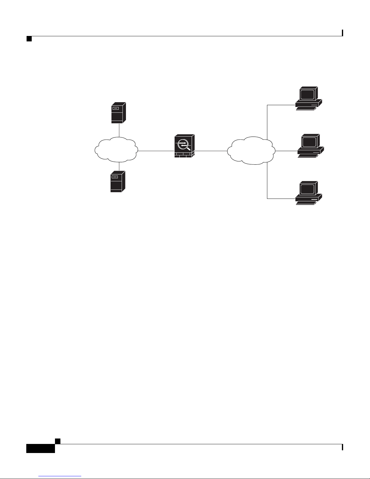
Figure 3-1 shows an security appliance configured to accept requests from and
establish IPsec connections with VPN clients, such as a Cisco Easy VPN
hardware client, over the Internet.
PIX 515E Security Appliance Getting Started Guide
78-17645-01
3-1
Page 44
Implementing the IPsec Remote-Access VPN Scenario
Figure 3-1 Network Layout for Remote Access VPN Scenario
DNS Server
10.10.10.163
Chapter 3 Scenario: IPsec Remote-Access VPN Configuration
VPN client
(user 1)
VPN client
VPN client
(user 3)
Internal
network
WINS Server
10.10.10.133
Inside
10.10.10.0
Security
Appliance
Outside
Internet
Implementing the IPsec Remote-Access VPN
Scenario
(user 2)
132209
3-2
This section describes how to configure the security appliance to accept IPsec
VPN connections from remote clients and devices. If you are implementing an
Easy VPN solution, this section describes how to configure an Easy VPN server
(also known as a headend device).
Values for example configuration settings are taken from the remote-access
scenario illustrated in Figure 3-1.
This section includes the following topics:
• Information to Have Available, page 3-3
• Starting ASDM, page 3-3
• Configuring the PIX 515E for an IPsec Remote-Access VPN, page 3-5
• Selecting VPN Client Types, page 3-6
PIX 515E Security Appliance Getting Started Guide
78-17645-01
Page 45

Chapter 3 Scenario: IPsec Remote-Access VPN Configuration
• Specifying the VPN Tunnel Group Name and Authentication Method,
page 3-7
• Specifying a User Authentication Method, page 3-8
• (Optional) Configuring User Accounts, page 3-10
• Configuring Address Pools, page 3-11
• Configuring Client Attributes, page 3-12
• Configuring the IKE Policy, page 3-13
• Configuring IPsec Encryption and Authentication Parameters, page 3-15
• Specifying Address Translation Exception and Split Tunneling, page 3-16
• Verifying the Remote-Access VPN Configuration, page 3-17
Implementing the IPsec Remote-Access VPN Scenario
Information to Have Available
Before you begin configuring the security appliance to accept remote access IPsec
VPN connections, make sure that you have the following information available:
• Range of IP addresses to be used in an IP pool. These addresses are assigned
to remote VPN clients as they are successfully connected.
• List of users to be used in creating a local authentication database, unless you
are using a AAA server for authentication.
• Networking information to be used by remote clients when connecting to the
VPN, including:
–
IP addresses for the primary and secondary DNS servers
–
IP addresses for the primary and secondary WINS servers
–
Default domain name
–
List of IP addresses for local hosts, groups, and networks that should be
made accessible to authenticated remote clients
Starting ASDM
To run ASDM in a web browser, enter the factory default IP address in the address
field: https://192.168.1.1/admin/.
78-17645-01
PIX 515E Security Appliance Getting Started Guide
3-3
Page 46
Implementing the IPsec Remote-Access VPN Scenario
Note Remember to add the “s” in “https” or the connection fails. HTTPS
(HTTP over SSL) provides a secure connection between your browser
and the security appliance.
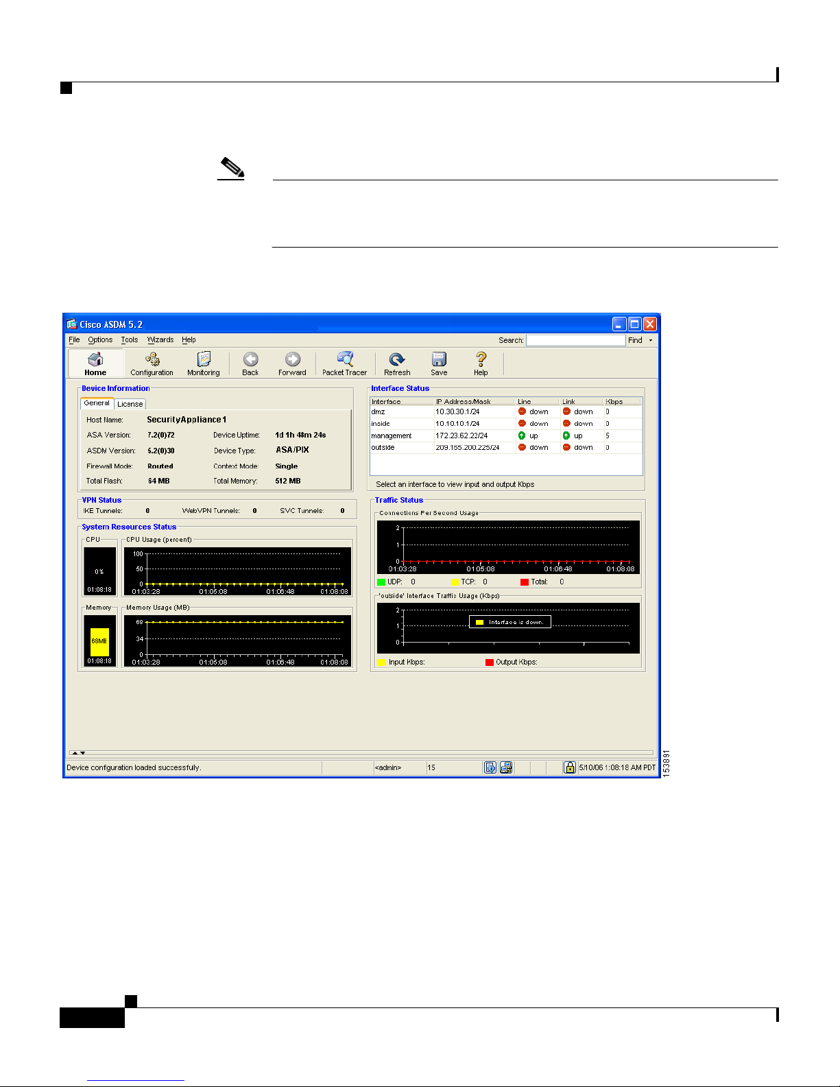
The Main ASDM window appears.
Chapter 3 Scenario: IPsec Remote-Access VPN Configuration
PIX 515E Security Appliance Getting Started Guide
3-4
78-17645-01
Page 47
Chapter 3 Scenario: IPsec Remote-Access VPN Configuration
Implementing the IPsec Remote-Access VPN Scenario
Configuring the PIX 515E for an IPsec Remote-Access VPN
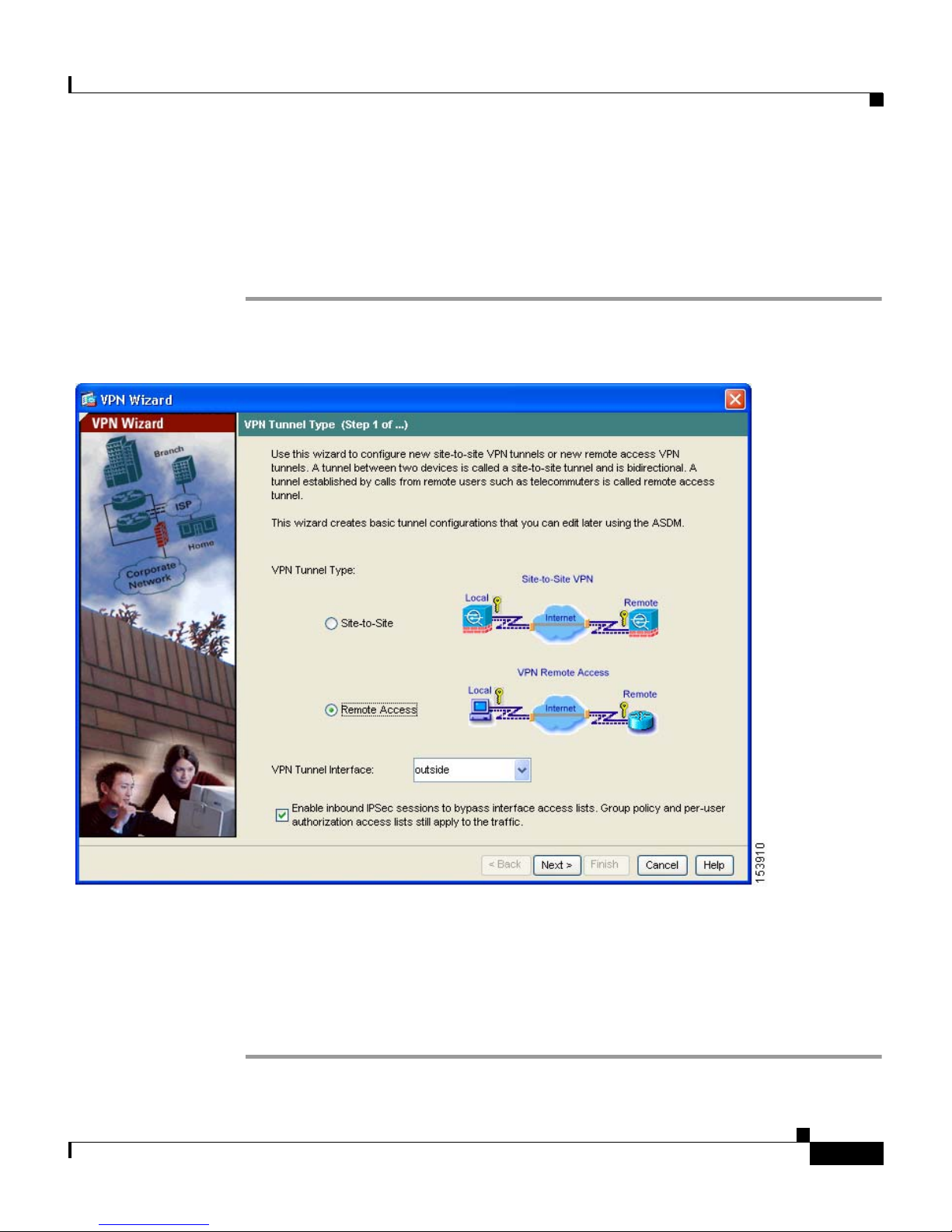
To begin the process for configuring a remote-access VPN, perform the following
steps:
Step 1 In the main ASDM window, choose VPN Wizard from the Wizards drop-down
menu. The VPN Wizard Step 1 screen appears.
Step 2 In Step 1 of the VPN Wizard, perform the following steps:
a. Click the Remote Access VPN radio button.
b. From the drop-down list, choose Outside as the enabled interface for the
incoming VPN tunnels.
c. Click Next to continue.
78-17645-01
PIX 515E Security Appliance Getting Started Guide
3-5
Page 48
Implementing the IPsec Remote-Access VPN Scenario
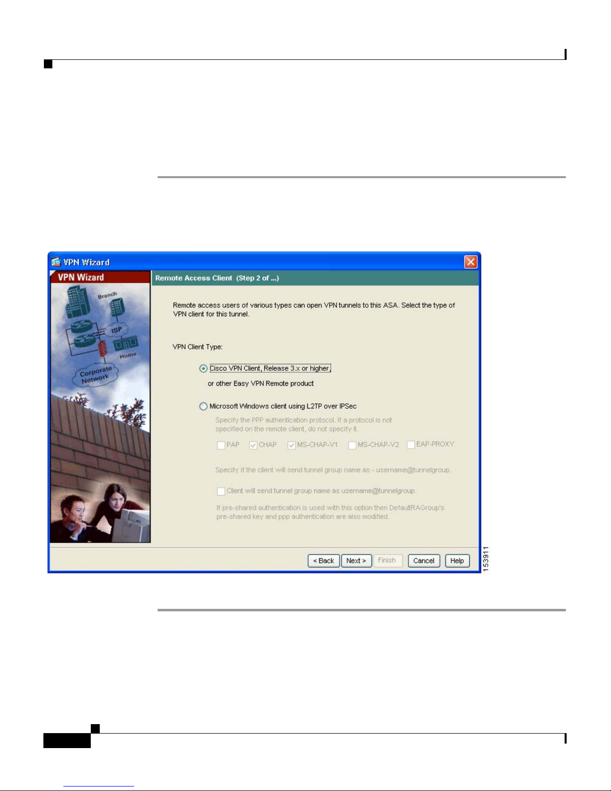
Selecting VPN Client Types
In Step 2 of the VPN Wizard, perform the following steps:
Step 1 Specify the type of VPN client that will enable remote users to connect to this
security appliance. For this scenario, click the Cisco VPN Client radio button.
You can also use any other Cisco Easy VPN remote product.
Chapter 3 Scenario: IPsec Remote-Access VPN Configuration
Step 2 Click Next to continue.
PIX 515E Security Appliance Getting Started Guide
3-6
78-17645-01
Page 49

Chapter 3 Scenario: IPsec Remote-Access VPN Configuration
Implementing the IPsec Remote-Access VPN Scenario
Specifying the VPN Tunnel Group Name and Authentication
Method
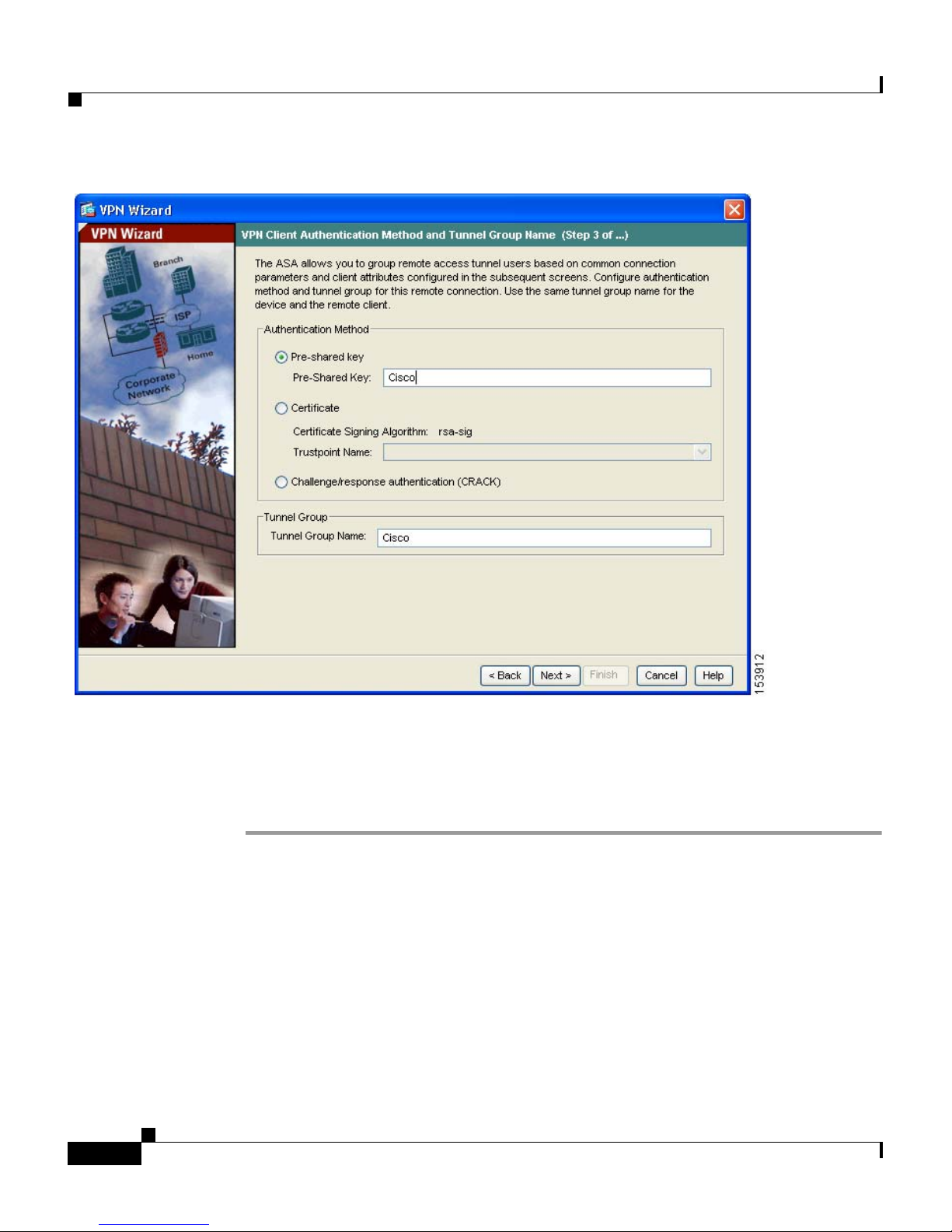
In Step 3 of the VPN Wizard, perform the following steps:
Step 1 Specify the type of authentication that you want to use by performing one of the
following steps:
• To use a static preshared key for authentication, click the Pre-Shared Key
radio button and enter a preshared key (for example, “Cisco”). This key is
used for IPsec negotiations between the security appliances.
• To use digital certificates for authentication, click the Certificate radio
button, choose the Certificate Signing Algorithm from the drop-down list,
and then choose a preconfigured trustpoint name from the drop-down list.
If you want to use digital certificates for authentication but have not yet
configured a trustpoint name, you can continue with the Wizard by using one
of the other two options. You can revise the authentication configuration later
using the standard ASDM screens.
• Click the Challenge/Response Authentication (CRACK) radio button to
use that method of authentication.
78-17645-01
PIX 515E Security Appliance Getting Started Guide
3-7
Page 50
Implementing the IPsec Remote-Access VPN Scenario
Chapter 3 Scenario: IPsec Remote-Access VPN Configuration
Step 2 Enter a Tunnel Group Name (such as “Cisco”) for the set of users that use
common connection parameters and client attributes to connect to this security
appliance.
Step 3 Click Next to continue.
Specifying a User Authentication Method
Users can be authenticated either by a local authentication database or by using
external authentication, authorization, and accounting (AAA) servers (RADIUS,
TACACS+, SDI, NT, Kerberos, and LDAP).
PIX 515E Security Appliance Getting Started Guide
3-8
78-17645-01
Page 51
Chapter 3 Scenario: IPsec Remote-Access VPN Configuration
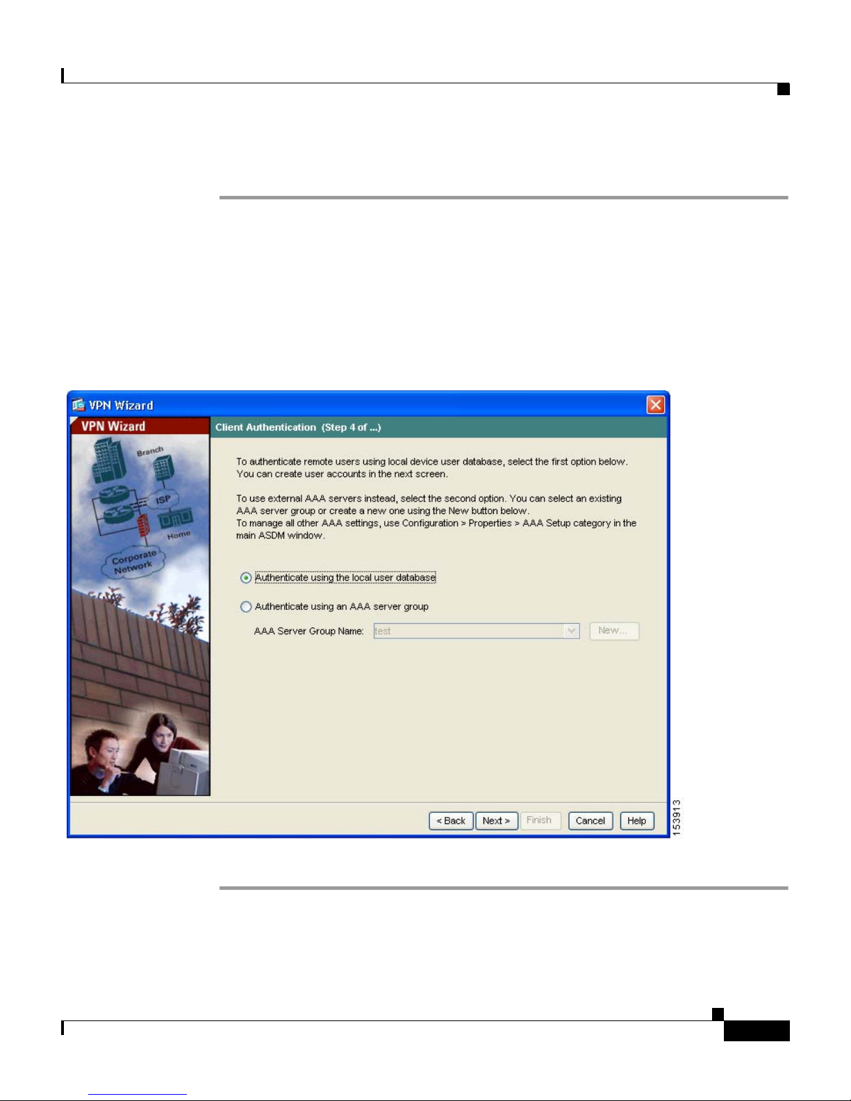
In Step 4 of the VPN Wizard, perform the following steps:
Step 1 If you want to authenticate users by creating a user database on the security
appliance, click the Authenticate Using the Local User Database radio button.
Step 2 If you want to authenticate users with an external AAA server group:
a. Click the Authenticate Using an AAA Server Group radio button.
b. Choose a preconfigured server group from the drop-down list, or click New
to add a new server group.
Implementing the IPsec Remote-Access VPN Scenario
Step 3 Click Next to continue.
78-17645-01
PIX 515E Security Appliance Getting Started Guide
3-9
Page 52
Chapter 3 Scenario: IPsec Remote-Access VPN Configuration
Implementing the IPsec Remote-Access VPN Scenario
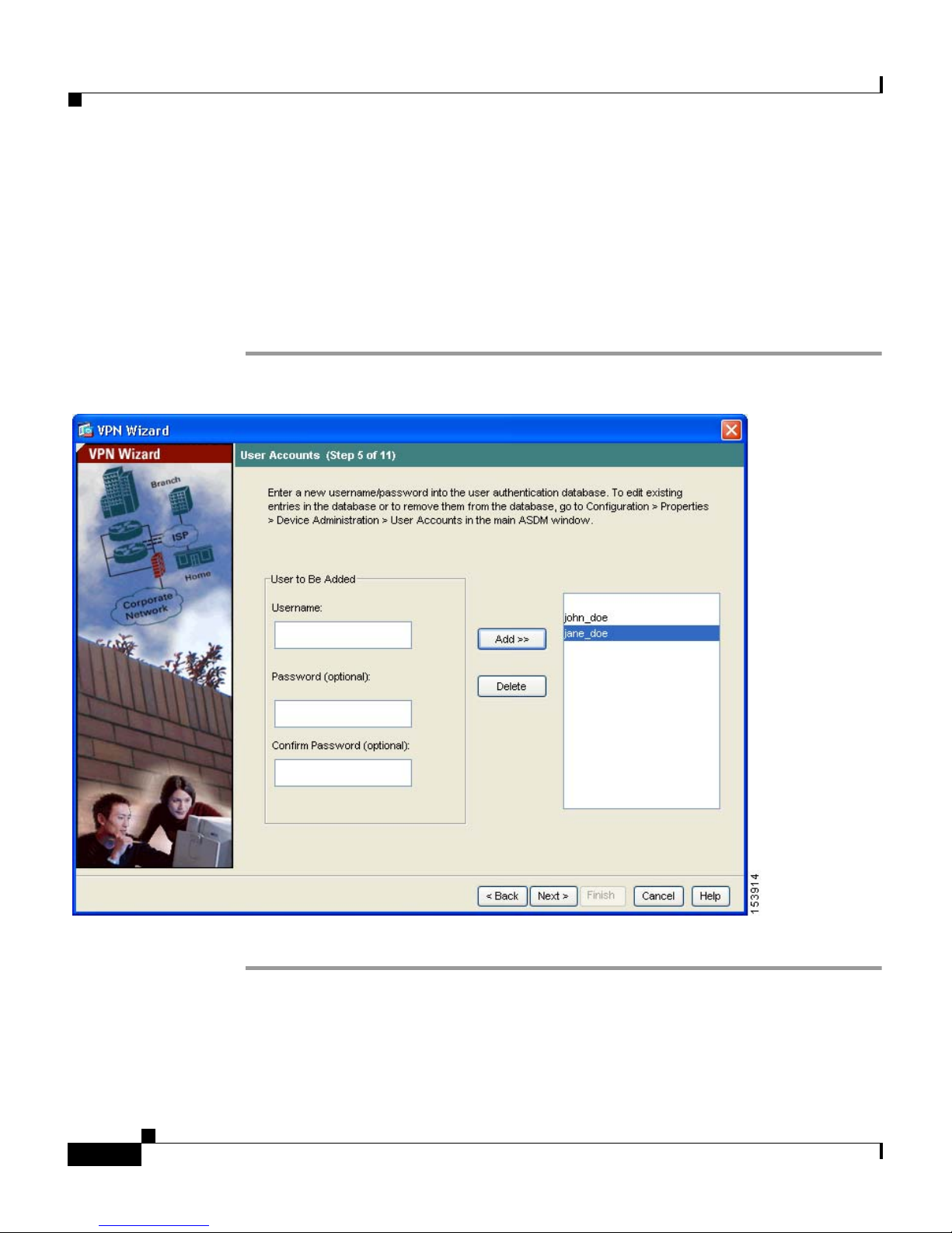
(Optional) Configuring User Accounts
If you have chosen to authenticate users with the local user database, you can
create new user accounts here. You can also add users later using the ASDM
configuration interface.
In Step 5 of the VPN Wizard, perform the following steps:
Step 1 To add a new user, enter a username and password, and then click Add.
Step 2 When you have finished adding new users, click Next to continue.
PIX 515E Security Appliance Getting Started Guide
3-10
78-17645-01
Page 53
Chapter 3 Scenario: IPsec Remote-Access VPN Configuration
Configuring Address Pools
For remote clients to gain access to your network, you must configure a pool of
IP addresses that can be assigned to remote VPN clients as they are successfully
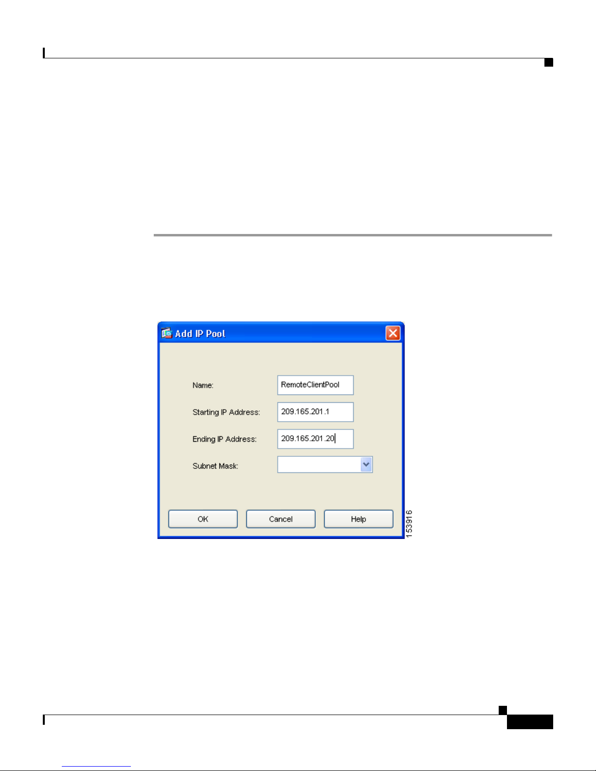
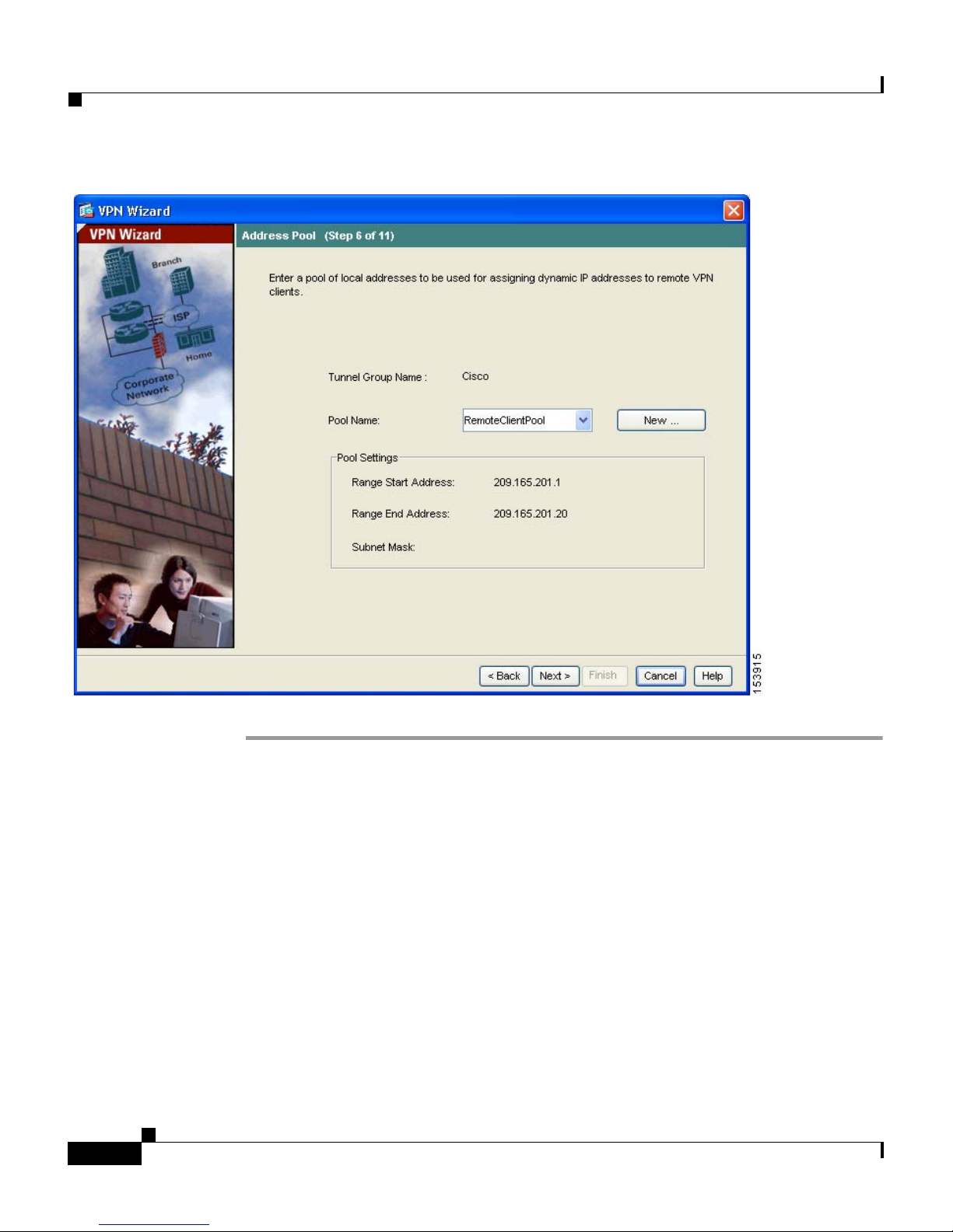
connected. In this scenario, the pool is configured to use the range of IP addresses
209.165.201.1–209.166.201.20.
In Step 6 of the VPN Wizard, perform the following steps:
Step 1 Enter a pool name or choose a preconfigured pool from the drop-down list.
Alternatively, click New to create a new address pool.
The Add IP Pool dialog box appears.
Implementing the IPsec Remote-Access VPN Scenario
Step 2 In the Add IP Pool dialog box:
a. Enter the Starting IP address and Ending IP address of the range.
b. (Optional) Enter the Netmask for the range of IP addresses.
c. Click OK to return to Step 6 of the VPN Wizard.
78-17645-01
PIX 515E Security Appliance Getting Started Guide
3-11
Page 54
Implementing the IPsec Remote-Access VPN Scenario
Chapter 3 Scenario: IPsec Remote-Access VPN Configuration
Step 3 Click Next to continue.
Configuring Client Attributes
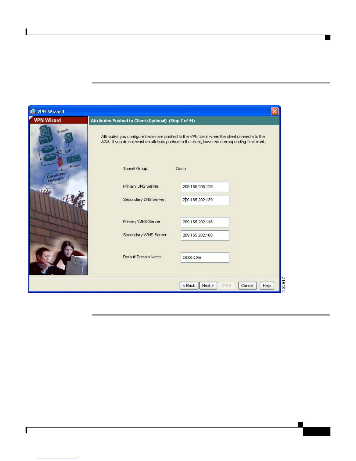
To access your network, each remote access client needs basic network
configuration information, such as which DNS and WINS servers to use and the
default domain name. Rather than configuring each remote client individually,
you can provide the client information to ASDM. The security appliance pushes
this information to the remote client or Easy VPN hardware client when a
connection is established.
Ensure that you specify the correct values, or remote clients will not be able to
use DNS names for resolution or use Windows networking.
PIX 515E Security Appliance Getting Started Guide
3-12
78-17645-01
Page 55
Chapter 3 Scenario: IPsec Remote-Access VPN Configuration
In Step 7 of the VPN Wizard, perform the following steps:
Step 1 Enter the network configuration information to be pushed to remote clients.
Implementing the IPsec Remote-Access VPN Scenario
Step 2 Click Next to continue.
Configuring the IKE Policy
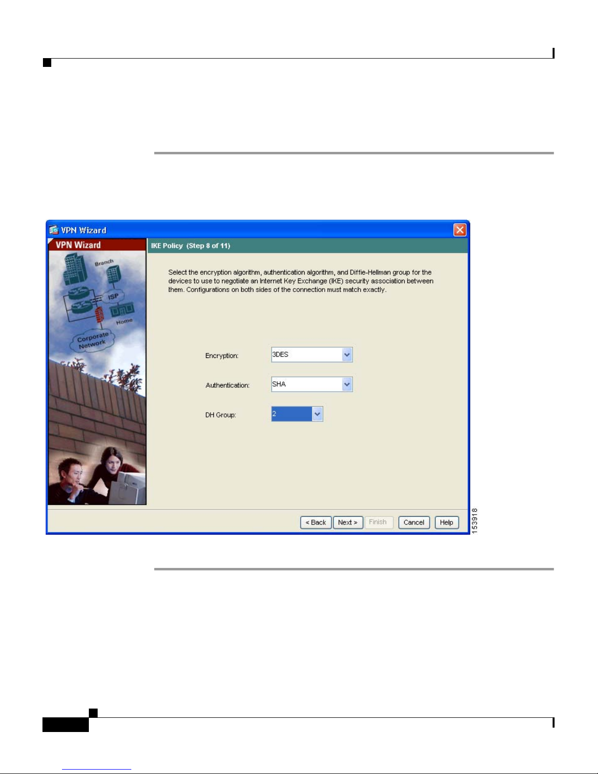
IKE is a negotiation protocol that includes an encryption method to protect data
and ensure privacy; it is also an authentication method to ensure the identity of
the peers. In most cases, the ASDM default values are sufficient to establish
secure VPN tunnels.
78-17645-01
PIX 515E Security Appliance Getting Started Guide
3-13
Page 56
Implementing the IPsec Remote-Access VPN Scenario
To specify the IKE policy in Step 8 of the VPN Wizard, perform the following
steps:
Step 1 Click the Encryption (DES/3DES/AES), authentication algorithms (MD5/SHA),
and the Diffie-Hellman group (1/2/5/7) used by the
IKE security association.
Chapter 3 Scenario: IPsec Remote-Access VPN Configuration
security appliance during an
Step 2 Click Next to continue.
PIX 515E Security Appliance Getting Started Guide
3-14
78-17645-01
Page 57
Chapter 3 Scenario: IPsec Remote-Access VPN Configuration
Implementing the IPsec Remote-Access VPN Scenario
Configuring IPsec Encryption and Authentication Parameters
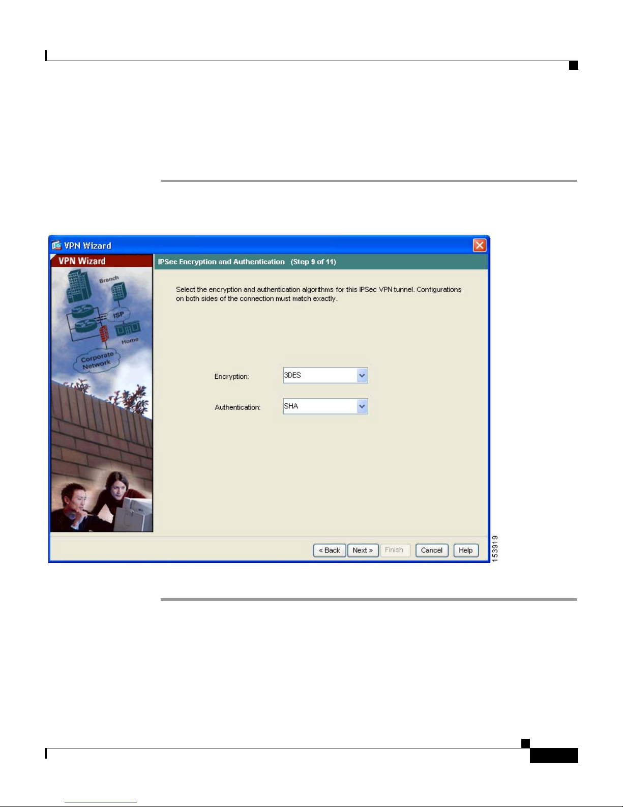
In Step 9 of the VPN Wizard, perform the following steps:
Step 1 Click the Encryption algorithm (DES/3DES/AES) and authentication algorithm
(MD5/SHA).
Step 2 Click Next to continue.
78-17645-01
PIX 515E Security Appliance Getting Started Guide
3-15
Page 58
Chapter 3 Scenario: IPsec Remote-Access VPN Configuration
Implementing the IPsec Remote-Access VPN Scenario
Specifying Address Translation Exception and Split Tunneling
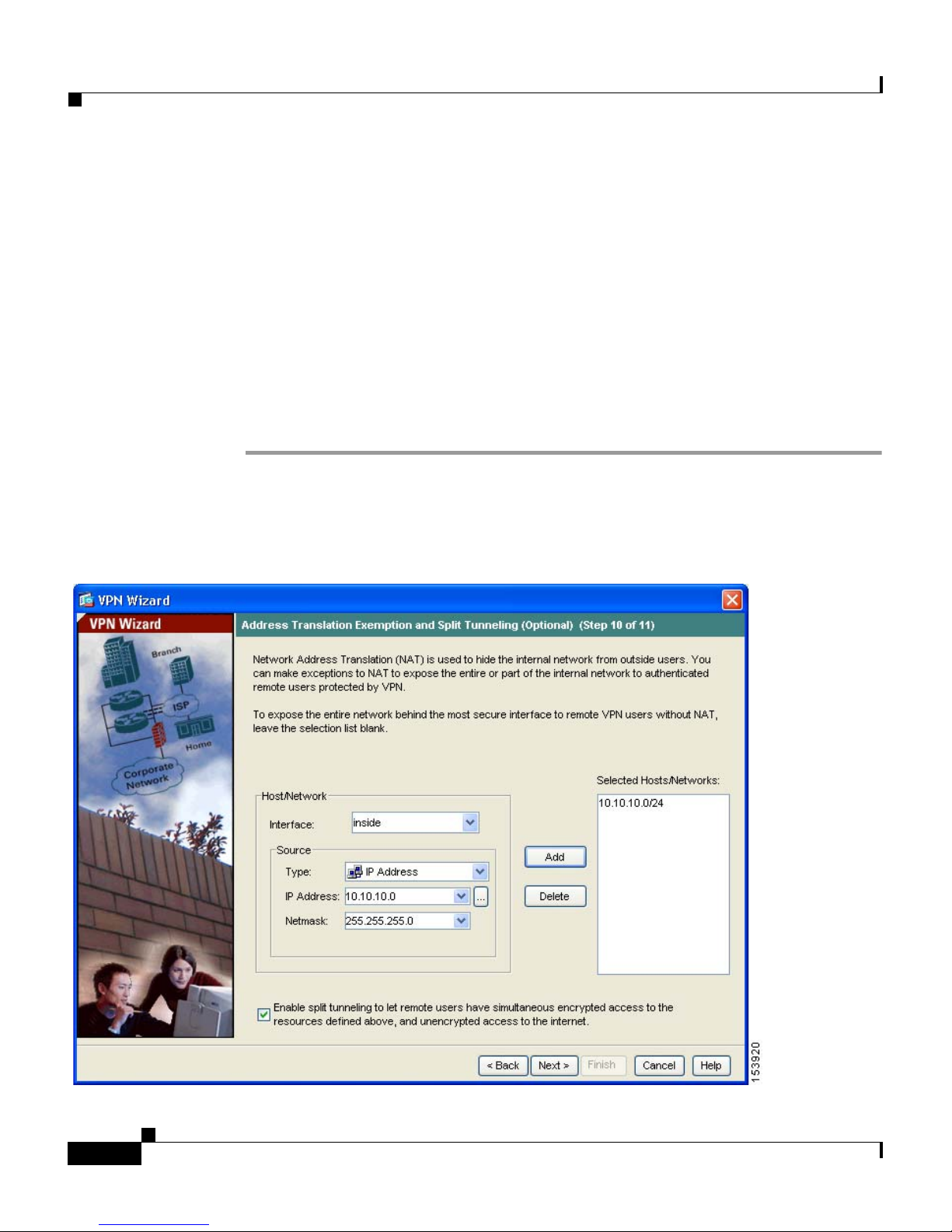
Split tunneling lets a remote-access IPsec client conditionally direct packets over
an IPsec tunnel in encrypted form or to a network interface in clear text form.
The security appliance uses Network Address Translation (NAT) to prevent
internal IP addresses from being exposed externally. You can make exceptions to
this network protection by identifying local hosts and networks that should be
made accessible to authenticated remote users. (In this scenario, the entire inside
network 10.10.10.0 is exposed to all remote clients.)
In Step 10 of the VPN Wizard, perform the following steps:
Step 1 Specify hosts, groups, and networks that should be in the list of internal resources
made accessible to authenticated remote users.
To add or remove hosts, groups, and networks dynamically from the Selected
Hosts/Networks pane, click Add or Delete, respectively.
PIX 515E Security Appliance Getting Started Guide
3-16
78-17645-01
Page 59
Chapter 3 Scenario: IPsec Remote-Access VPN Configuration
Implementing the IPsec Remote-Access VPN Scenario
Note Enable split tunneling by checking the Enable Split Tunneling check
box at the bottom of the screen. Split tunneling allows traffic outside the
configured networks to be sent out directly to the Internet instead of over
the encrypted VPN tunnel.
Step 2 Click Next to continue.
Verifying the Remote-Access VPN Configuration
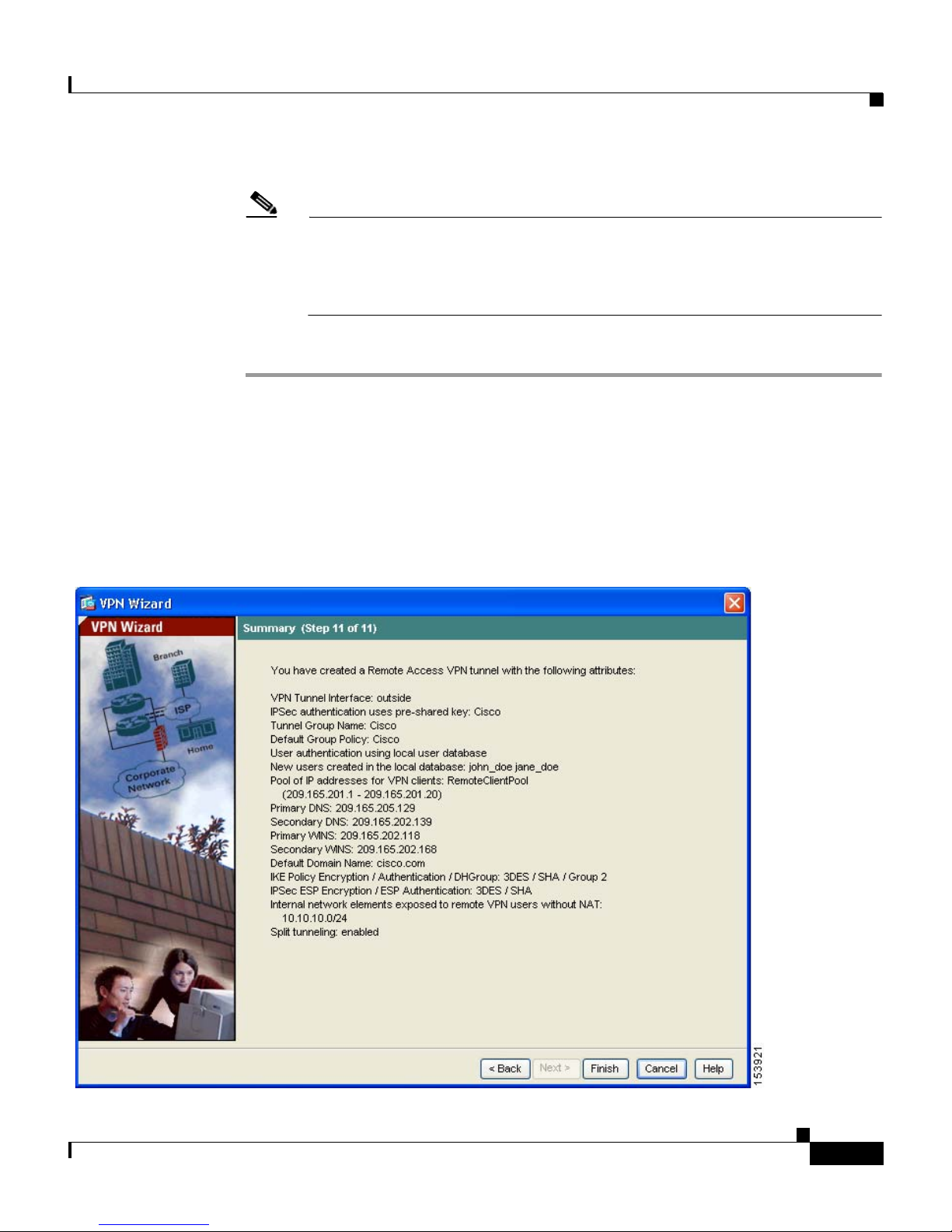
In Step 11 of the VPN Wizard, review the configuration attributes for the VPN
tunnel you just created. The displayed configuration should be similar to the
following:
78-17645-01
PIX 515E Security Appliance Getting Started Guide
3-17
Page 60

What to Do Next
If you are satisfied with the configuration, click Finish to apply the changes to the
security appliance.
If you want the configuration changes to be saved to the startup configuration so
that they are applied the next time the device starts, from the File menu, click
Save. Alternatively, ASDM prompts you to save the configuration changes
permanently when you exit ASDM.
If you do not save the configuration changes, the old configuration takes effect
the next time the device starts.
What to Do Next
Chapter 3 Scenario: IPsec Remote-Access VPN Configuration
If you are deploying the security appliance solely in a remote-access VPN
environment, you have completed the initial configuration. In addition, you may
want to consider performing some of the following steps:
To Do This ... See ...
Refine configuration and configure
optional and advanced features
Cisco Security Appliance Command
Line Configuration Guide
Learn about daily operations Cisco Security Appliance Command
Reference
Cisco Security Appliance Logging
Configuration and System Log
Messages
You can configure the
security appliance for more than one application. The
following sections provide configuration procedures for other common
applications of the
security appliance.
PIX 515E Security Appliance Getting Started Guide
3-18
78-17645-01
Page 61

Chapter 3 Scenario: IPsec Remote-Access VPN Configuration
To Do This ... See ...
What to Do Next
Configure the
protect a Web server in a DMZ
security appliance to
Chapter 2, “Scenario: DMZ
Configuration”
Configure a site-to-site VPN Chapter 4, “Scenario: Site-to-Site
VPN Configuration”
78-17645-01
PIX 515E Security Appliance Getting Started Guide
3-19
Page 62

What to Do Next
Chapter 3 Scenario: IPsec Remote-Access VPN Configuration
PIX 515E Security Appliance Getting Started Guide
3-20
78-17645-01
Page 63

CHAPTER
4
Scenario: Site-to-Site VPN
Configuration
This chapter describes how to use the security appliance to create a site-to-site
VPN.
Site-to-site VPN features provided by the security appliance enable businesses to
extend their networks across low-cost public Internet connections to business
partners and remote offices worldwide while maintaining their network security.
A VPN connection enables you to send data from one location to another over a
secure connection, or tunnel, first by authenticating both ends of the connection,
and then by automatically encrypting all data sent between the two sites.
This chapter includes the following sections:
• Example Site-to-Site VPN Network Topology, page 4-1
• Implementing the Site-to-Site Scenario, page 4-2
• Configuring the Other Side of the VPN Connection, page 4-13
• What to Do Next, page 4-13
Example Site-to-Site VPN Network Topology
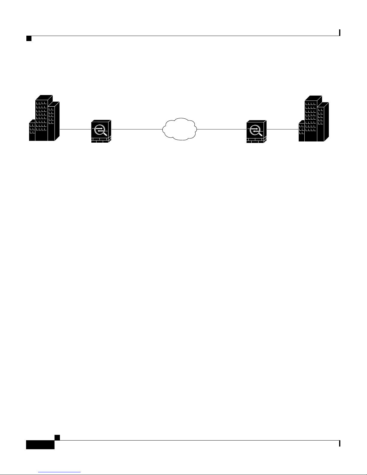
Figure 4-1 shows an example VPN tunnel between two security appliances.
PIX 515E Security Appliance Getting Started Guide
78-17645-01
4-1
Page 64
Chapter 4 Scenario: Site-to-Site VPN Configuration
Implementing the Site-to-Site Scenario
Figure 4-1 Network Layout for Site-to-Site VPN Configuration Scenario
Site A
Inside
10.10.10.0
Security
Appliance 1
209.165.200.226
Outside
Internet
Outside
209.165.200.236
Security
Appliance 2
Creating a VPN site-to-site deployment such as the one in Figure 4-1 requires you
to configure two security appliances, one on each side of the connection.
Implementing the Site-to-Site Scenario
This section describes how to configure the security appliance in a site-to-site
VPN deployment, using example parameters from the remote-access scenario
shown in Figure 4-1.
This section includes the following sections:
• Information to Have Available, page 4-2
Inside
10.20.20.0
Site B
132066
• Configuring the Site-to-Site VPN, page 4-3
Information to Have Available
Before you begin the configuration procedure, gather the following information:
• IP address of the remote security appliance peer
• IP addresses of local hosts and networks permitted to use the tunnel to
communicate with resources on the remote site
• IP addresses of remote hosts and networks permitted to use the tunnel to
communicate with local resources
PIX 515E Security Appliance Getting Started Guide
4-2
78-17645-01
Page 65

Chapter 4 Scenario: Site-to-Site VPN Configuration
Configuring the Site-to-Site VPN
This section describes how to use the ASDM VPN Wizard to configure the
security appliance for a site-to-site VPN.
This section includes the following topics:
• Starting ASDM, page 4-3
• Configuring the Security Appliance at the Local Site, page 4-4
• Providing Information About the Remote VPN Peer, page 4-6
• Configuring the IKE Policy, page 4-7
• Configuring IPsec Encryption and Authentication Parameters, page 4-9
• Specifying Hosts and Networks, page 4-10
• Viewing VPN Attributes and Completing the Wizard, page 4-11
Implementing the Site-to-Site Scenario
Starting ASDM
The following sections provide detailed instructions for how to perform each
configuration step.
To run ASDM in a web browser, enter the factory default IP address in the address
field: https://192.168.1.1/admin/.
Note Remember to add the “s” in “https” or the connection fails. HTTPS
(HTTP over SSL) provides a secure connection between your browser
and the security appliance.
The Main ASDM window appears.
78-17645-01
PIX 515E Security Appliance Getting Started Guide
4-3
Page 66
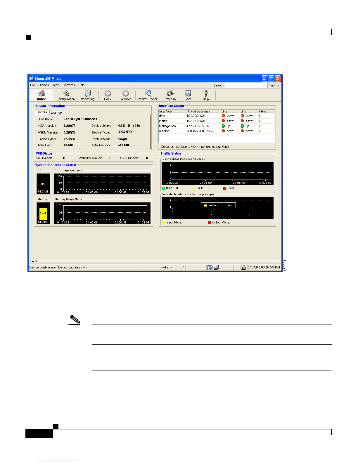
Implementing the Site-to-Site Scenario
Chapter 4 Scenario: Site-to-Site VPN Configuration
Configuring the Security Appliance at the Local Site
Note The security appliance at the first site is referred to as Security Appliance 1 from
this point forward.
To configure the Security Appliance 1, perform the following steps:
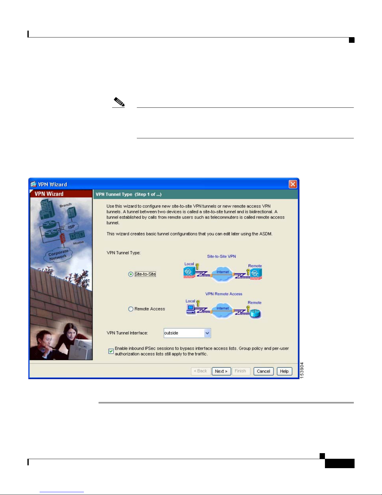
Step 1 In the main ASDM window, choose the VPN Wizard option from the Wizards
drop-down menu. ASDM opens the first VPN Wizard screen.
PIX 515E Security Appliance Getting Started Guide
4-4
78-17645-01
Page 67
Chapter 4 Scenario: Site-to-Site VPN Configuration
In Step 1 of the VPN Wizard, perform the following steps:
a. Click the Site-to-Site VPN radio button.
Note The Site-to-Site VPN option connects two IPsec security gateways,
which can include security appliances, VPN concentrators, or other
devices that support site-to-site IPsec connectivity.
b. From the drop-down list, choose Outside as the enabled interface for the
current VPN tunnel.
Implementing the Site-to-Site Scenario
c. Click Next to continue.
78-17645-01
PIX 515E Security Appliance Getting Started Guide
4-5
Page 68

Chapter 4 Scenario: Site-to-Site VPN Configuration
Implementing the Site-to-Site Scenario
Providing Information About the Remote VPN Peer
The VPN peer is the system on the other end of the connection that you are
configuring, usually at a remote site.
Note In this scenario, the remote VPN peer is referred to as Security Appliance 2 from
this point forward.
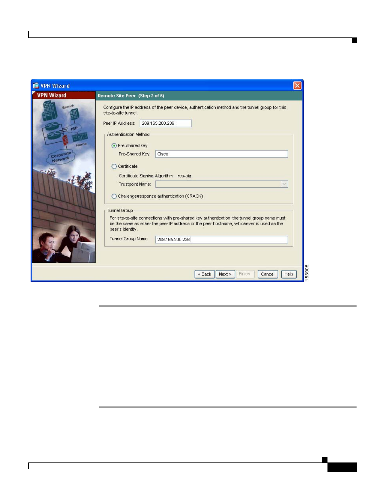
In Step 2 of the VPN Wizard, perform the following steps:
Step 1 Enter the Peer IP Address (the IP address of Security Appliance 2, in this scenario
209.165.200.236) and a Tunnel Group Name (for example “Cisco”).
Step 2 Specify the type of authentication that you want to use by performing one of the
following steps:
• To use a static preshared key for authentication, click the Pre-Shared Key
radio button and enter a preshared key (for example, “Cisco”). This key is
used for IPsec negotiations between the security appliances.
Note When you configure Security Appliance 2 at the remote site, the VPN
peer is Security Appliance 1. Be sure to enter the same preshared key
(Cisco) that you use here.
• Click the Challenge/Response Authentication radio button to use that
method of authentication.
• To use digital certificates for authentication, click the Certificate radio
button, choose the Certificate Signing Algorithm from the drop-down list,
and then choose a preconfigured trustpoint name from the drop-down list.
If you want to use digital certificates for authentication but have not yet
configured a trustpoint name, you can continue with the Wizard by using one
of the other two options. You can revise the authentication configuration later
using the standard ASDM screens.
PIX 515E Security Appliance Getting Started Guide
4-6
78-17645-01
Page 69
Chapter 4 Scenario: Site-to-Site VPN Configuration
Implementing the Site-to-Site Scenario
Step 3 Click Next to continue.
Configuring the IKE Policy
IKE is a negotiation protocol that includes an encryption method to protect data
and ensure privacy; it is also an authentication method to ensure the identity of
the peers. In most cases, the ASDM default values are sufficient to establish
secure VPN tunnels between two peers.
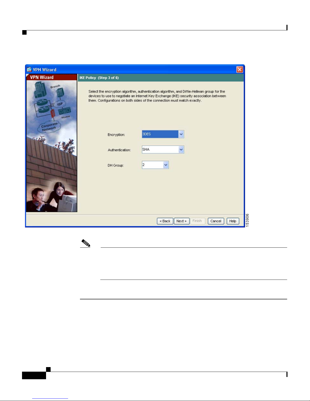
In Step 3 of the VPN Wizard, perform the following steps:
Step 1 Click the Encryption (DES/3DES/AES), authentication algorithms (MD5/SHA),
and the Diffie-Hellman group (1/2/5) used by the security appliance during an
IKE security association.
78-17645-01
PIX 515E Security Appliance Getting Started Guide
4-7
Page 70
Implementing the Site-to-Site Scenario
Chapter 4 Scenario: Site-to-Site VPN Configuration
Note When configuring Security Appliance 2, enter the exact values for each
of the options that you chose for Security Appliance 1. Encryption
mismatches are a common cause of VPN tunnel failures and can slow
down the process.
Step 2 Click Next to continue.
PIX 515E Security Appliance Getting Started Guide
4-8
78-17645-01
Page 71
Chapter 4 Scenario: Site-to-Site VPN Configuration
Implementing the Site-to-Site Scenario
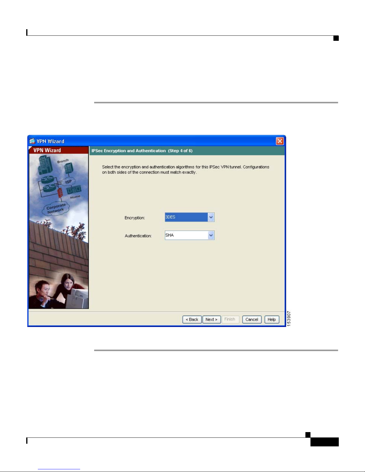
Configuring IPsec Encryption and Authentication Parameters
In Step 4 of the VPN Wizard, perform the following steps:
Step 1 Choose the Encryption algorithm (DES/3DES/AES) and authentication algorithm
(MD5/SHA) from the drop-down lists.
Step 2 Click Next to continue.
78-17645-01
PIX 515E Security Appliance Getting Started Guide
4-9
Page 72

Implementing the Site-to-Site Scenario
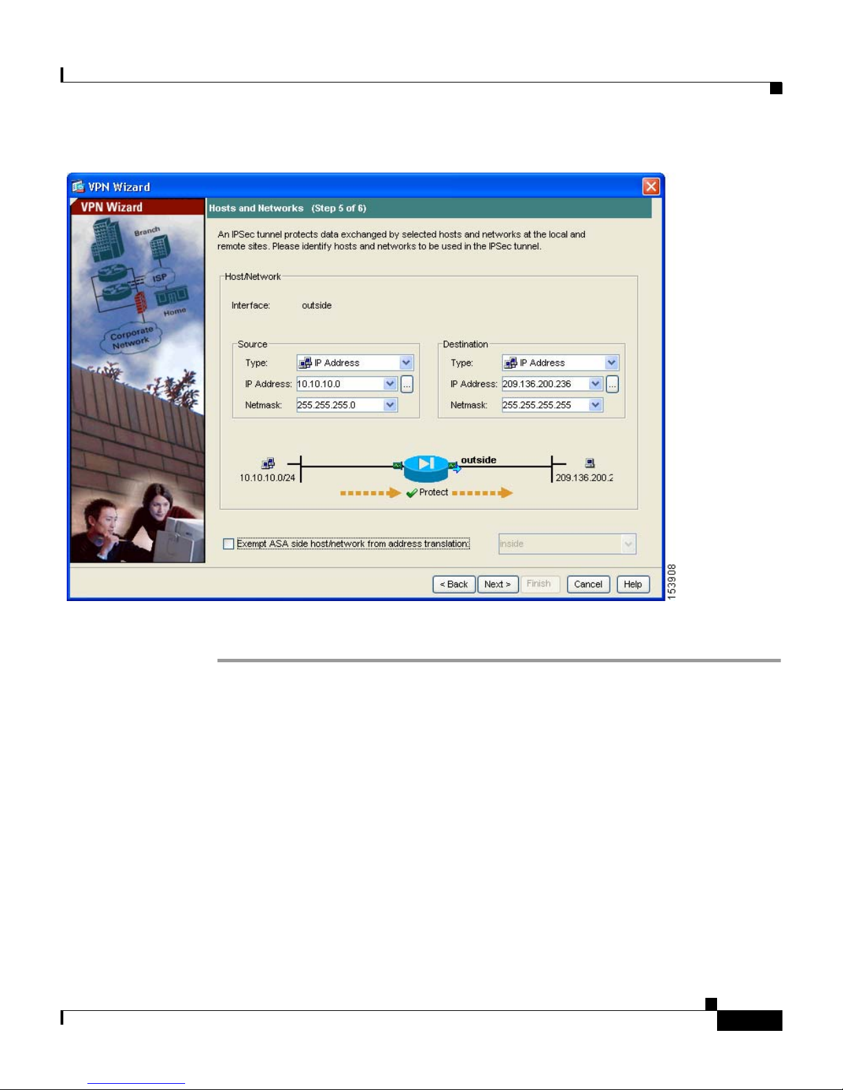
Specifying Hosts and Networks
Identify hosts and networks at the local site that are permitted to use this IPsec
tunnel to communicate with the remote-site peer. Add or remove hosts and
networks dynamically by clicking Add or Delete, respectively. In the current
scenario, traffic from Network A (10.10.10.0) is encrypted by Security
Appliance 1 and transmitted through the VPN tunnel.
In addition, identify hosts and networks at the remote site to be allowed to use this
IPsec tunnel to access local hosts and networks. Add or remove hosts and
networks dynamically by clicking Add or Delete respectively. In this scenario,
for Security Appliance 1, the remote network is Network B (10.20.20.0), so
traffic encrypted from this network is permitted through the tunnel.
In Step 5 of the VPN Wizard, perform the following steps:
Step 1 In the Source area, choose IP Address from the Type drop-down list.
Chapter 4 Scenario: Site-to-Site VPN Configuration
Step 2 Enter the local IP address and netmask in the IP Address and Netmask fields.
Step 3 In the Destination area, choose IP Address from the Type drop-down list.
Step 4 Enter the IP address and Netmask for the remote host or network.
PIX 515E Security Appliance Getting Started Guide
4-10
78-17645-01
Page 73
Chapter 4 Scenario: Site-to-Site VPN Configuration
Implementing the Site-to-Site Scenario
Step 5 Click Next to continue.
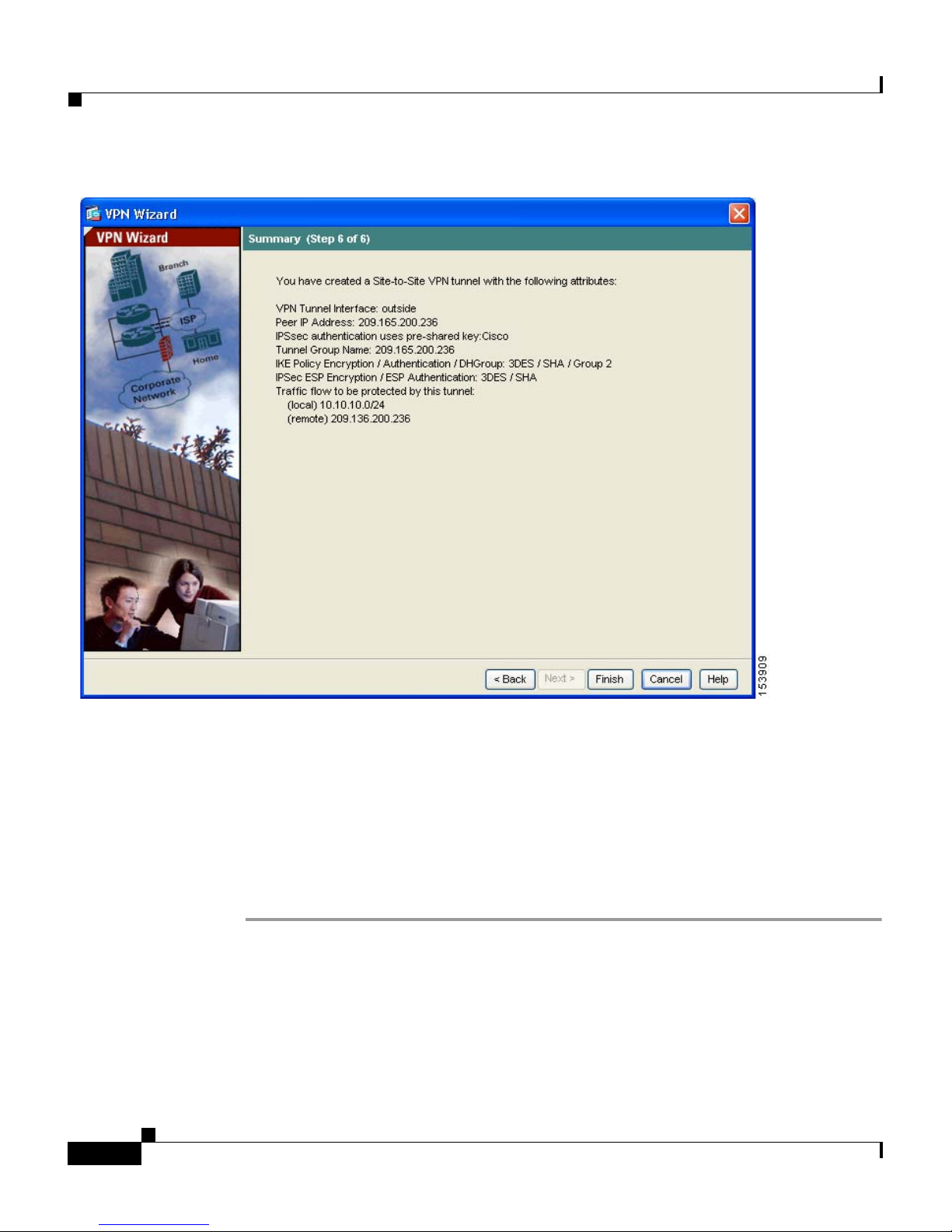
Viewing VPN Attributes and Completing the Wizard
In Step 6 of the VPN Wizard, review the configuration list for the VPN tunnel you
just created. If you are satisfied with the configuration, click Finish to apply the
changes to the security appliance.
PIX 515E Security Appliance Getting Started Guide
78-17645-01
4-11
Page 74
Implementing the Site-to-Site Scenario
Chapter 4 Scenario: Site-to-Site VPN Configuration
4-12
Step 6 If you want the configuration changes to be saved to the startup configuration so
that they are applied the next time the device starts, from the File menu, click
Save.
Alternatively, ASDM prompts you to save the configuration changes permanently
when you exit ASDM.
If you do not save the configuration changes, the old configuration takes effect
the next time the device starts.
This concludes the configuration process for Security Appliance 1.
PIX 515E Security Appliance Getting Started Guide
78-17645-01
Page 75

Chapter 4 Scenario: Site-to-Site VPN Configuration
Configuring the Other Side of the VPN Connection
Configuring the Other Side of the VPN Connection
You have just configured the local security appliance. Now you need to configure
the security appliance at the remote site.
At the remote site, configure the second security appliance to serve as a VPN peer.
Use the procedure you used to configure the local security appliance, starting with
the “Configuring the Security Appliance at the Local Site” section on page 4-4
and finishing with the “Viewing VPN Attributes and Completing the Wizard”
section on page 4-11.
Note When configuring Security Appliance 2, enter the exact same values for each of
the options that you selected for Security Appliance 1. Mismatches are a common
cause of VPN configuration failures.
What to Do Next
If you are deploying the security appliance solely in a site-to-site VPN
environment, you have completed the initial configuration. In addition, you may
want to consider performing some of the following steps:
To Do This ... See ...
Refine configuration and configure
optional and advanced features
Learn about daily operations Cisco Security Appliance Command
Cisco Security Appliance Command
Line Configuration Guide
Reference
Cisco Security Appliance Logging
Configuration and System Log
Messages
78-17645-01
PIX 515E Security Appliance Getting Started Guide
4-13
Page 76

What to Do Next
Chapter 4 Scenario: Site-to-Site VPN Configuration
You can configure the security appliance for more than one application. The
following sections provide configuration procedures for other common
applications of the security appliance.
To Do This ... See ...
Configure the security appliance to
protect a web server in a DMZ
Chapter 2, “Scenario: DMZ
Configuration”
Configure a remote-access VPN Chapter 3, “Scenario: IPsec
Remote-Access VPN Configuration”
PIX 515E Security Appliance Getting Started Guide
4-14
78-17645-01
Page 77

CHAPTER
A
Obtaining a DES License or a
3DES-AES License
The Cisco PIX 515E security appliance is available either with a DES or
3DES-ASE license that provides encryption technology to enable specific
features, such as secure remote management (SSH, ASDM, and so on), site-to-site
VPN, and remote access VPN. The license is enabled through an encryption
license key.
If you ordered your security appliance with a DES or 3DES-AES license, the
encryption license key comes with the adaptive security appliance.
78-17645-01
If you are a registered user of Cisco.com and would like to obtain a 3DES/AES
encryption license, go to the following website:
http://www.cisco.com/go/license
If you are not a registered user of Cisco.com, go to the following website:
https://tools.cisco.com/SWIFT/Licensing/RegistrationServlet
Provide your name, e-mail address, and the serial number for the security
appliance as it appears in the show version command output.
Note You will receive the new activation key for your security appliance within two
hours of requesting the license upgrade.
For more information on activation key examples or upgrading software, see the
Cisco Security Appliance Command Line Configuration Guide.
PIX 515E Security Appliance Getting Started Guide
A-1
Page 78

Chapter A Obtaining a DES License or a 3DES-AES License
To use the activation key, perform the following steps:
Command Purpose
Step 1
Step 2
Step 3
Step 4
Step 5
hostname# show version
hostname# configure
terminal
hostname(config)#
activation-key
activation-5-tuple-key
hostname(config)# exit
hostname# copy
running-config
startup-config
Shows the software release, hardware
configuration, license key, and related
uptime data.
Enters global configuration mode.
Updates the encryption activation key by
replacing the activation-4-tuple-key
variable with the activation key obtained
with your new license. The
activation-5-tuple-key variable is a
five-element hexadecimal string with one
space between each element. An example is
0xe02888da 0x4ba7bed6 0xf1c123ae
0xffd8624e. The “0x” is optional; all values
are assumed to be hexadecimal.
Exits global configuration mode.
Saves the configuration.
A-2
Step 6
PIX 515E Security Appliance Getting Started Guide
hostname# reload
Reboots the security appliance and reloads
the configuration.
78-17645-01
 Loading...