

Page 1

Ripwave
®
MX PC Card (PMX)
40-00460-00R
May 22, 2008`
All information disclosed by this document is the proprietary property of Navini Networks, Inc. and is
protected by copyright, trademark, and/or trade secret laws. All rights therein are expressly reserved.
User Guide
Proprietary
Page 2

TABLE OF CONTENTS
TABLE OF CONTENTS ..........................................................................................................................2
PERMISSIONS, TRADEMARKS & DISTRIBUTION ....................................................................................... 4
SAFETY..................................................................................................................................................................... 5
REGULATORY INFORMATION......................................................................................................................... 6
INTRODUCTION..................................................................................................................................................... 7
PACKAGE INVENTORY....................................................................................................................................... 7
PMX MODELS......................................................................................................................................................... 8
MINIMUM COMPUTING REQUIREMENTS .................................................................................................... 8
PHYSICAL CHARACTERISTICS........................................................................................................................ 9
PMX FEATURES..................................................................................................................................................... 9
INSTALLING THE PMX......................................................................................................................................10
ACCESSING THE INTERNET............................................................................................................................13
REMOVING THE PMX........................................................................................................................................ 13
INDICATOR LIGHT............................................................................................................................................. 14
TROUBLESHOOTING ......................................................................................................................................... 14
INSTALLING NAVINI DIAGNOSTICS (NAVDIAG)...................................................................................... 15
TROUBLESHOOTING USING NAVINI DIAGNOSTICS............................................................................... 20
THE ICONS ...............................................................................................................................................20
THE SIGNAL STRENGTH AND SIGNAL QUALITY BARS..............................................................................21
THE HISTORY GRAPHS .............................................................................................................................22
HE PARAMETERS....................................................................................................................................22
T
THE SCREEN OPTION BUTTONS................................................................................................................23
T
HE CONFIGURATION SCREEN .................................................................................................................23
HE TREND ANALYSIS SCREEN................................................................................................................23
T
THE STATISTICS SCREEN..........................................................................................................................24
THE ABOUT SCREEN ................................................................................................................................25
THE HELP BUTTON ..................................................................................................................................25
UNINSTALLING NAVINI DIAGNOSTICS SOFTWARE ............................................................................... 26
OPTIONAL DESKTOP ANTENNA .................................................................................................................... 29
CONNECTING THE DESKTOP ANTENNA ....................................................................................................29
DISCONNECTING THE DESKTOP ANTENNA ...............................................................................................30
CARE & MAINTENANCE................................................................................................................................... 31
UPGRADING THE PMX SOFTWARE............................................................................................................... 32
MANUAL CDMA-TO-WIMAX PMX SOFTWARE UPGRADE..................................................................... 33
English_PMX_user_guide_2008-05-22_40-0460-00Re(6.2.7).doc Page 2
Page 3

WHAT COULD GO WRONG DURING THE PMX UPDATE ........................................................................ 37
ADDENDUM 1: INSTALLING NAVDIAG ON VISTA................................................................................... 39
ADDENDUM 2: PMX - PC TROUBLESHOOTING......................................................................................... 42
PC OPERATING SYSTEMS.........................................................................................................................42
MULTI-PC CONFIGURATIONS ..................................................................................................................42
RESULTS OF CORRECT NAVDIAG INSTALLATION.....................................................................................43
ADDENDUM 3: END USER SOFTWARE LICENSE AGREEMENT........................................................... 49
English_PMX_user_guide_2008-05-22_40-0460-00Re(6.2.7).doc Page 3
Page 4

Permissions, Trademarks & Distribution
Copyright© 2008, Navini Networks, Inc. All information contained herein and disclosed by this
document is confidential and the proprietary property of Navini Networks, Inc. and all rights therein are
expressly reserved. Acceptance of this material signifies agreement by the recipient that the information
contained in this document is confidential and that it will be used solely for the purposes set forth herein.
Acceptance of this material signifies agreement by the recipient that it will not be used, reproduced in
whole or in part, disclosed, distributed, or conveyed to others in any manner or by any means – graphic,
electronic, or mechanical, including photocopying, recording, taping, or information storage and retrieval
systems – without the express written permission of Navini Networks, Inc.
Navini Networks and Ripwave are registered trademarks. The Navini Networks logo, Zero-Install, and
Unwired by Navini are trademarks of Navini Networks, Inc. Other product and company names
mentioned herein may be trademarks and/or service marks of their respective owners.
Except for the hardware warranty, nothing herein constitutes any representation, warranty,
assurance, or guaranty of any kind.
Because of continuing developments and improvements in design, manufacturing, and deployment,
material in this document is subject to change without notification and does not represent any
commitment or obligation on the part of Navini Networks, Inc.
Navini Networks, Inc. shall have no liability for any error or damages resulting from the use of this
document.
All Navini Networks logos and trademarks are the property of Navini Networks, Inc. Unauthorized usage
is strictly prohibited without the express written permission of Navini Networks, Inc.
© 2008 Navini Networks, Inc. All rights reserved.
English_PMX_user_guide_2008-05-22_40-0460-00Re(6.2.7).doc Page 4
Page 5

Safety
To optimize safety and expedite installation and service, read this document thoroughly. Follow all
warnings, cautions, and instructions marked on the equipment and included in this document.
To aid in the prevention of injury and damage to property, cautionary symbols have been placed in this
document to alert the reader to known potentially hazardous situations, or hazards to equipment or
procedures. The symbols are placed before the information to which they apply. However, any situation
that involves heavy equipment and electricity can become hazardous, and caution and safety should be
practiced at all times when installing, servicing, or operating the equipment.
Caution Symbol - possible equipment or property damage.
Warning Symbol - could cause personal injury or otherwise be hazardous to
your health
Navini Networks, Inc., expressly requires that when using Navini electronic equipment always follow the
basic safety precautions to reduce the risk of electrical shock, fire, and injury to people and/or property.
1. Follow all warnings and instructions that come with the equipment.
2. Do not use the equipment while you are in a bathtub, shower, pool, or spa. Exposure of the
equipment to water could cause severe electrical shock or serious damage to the equipment.
3. Do not allow any type of liquid to come in contact with the equipment. Unplug the equipment from
the power source before cleaning. Use a damp cloth for cleaning. Do not use any soaps or liquid
cleaners.
4. Follow all airport and FAA regulations when using the equipment on or near aircraft.
5. Do not use the PMX near medical equipment, life support equipment, or any equipment that may be
susceptible to any form of radio interference. In such areas, the PMX must be powered off.
6. The driver or operator of any vehicle should not operate the PMX while in control of a vehicle. Doing
so will detract from the driver or operator’s control and operation of the vehicle.
7. Do not disassemble the equipment. Removing covers exposes dangerous voltages or other risks and
also voids the warranty. Incorrect reassembly can cause equipment damage or electrical shock. Only
an authorized repair technician should service this product.
8. Do not expose the equipment to extreme hot or cold temperatures.
9. Do not use the equipment under the following conditions:
• When the equipment has been exposed to water or moisture.
• When the equipment has been damaged.
• When the equipment does not operate properly or shows a distinct change in performance.
English_PMX_user_guide_2008-05-22_40-0460-00Re(6.2.7).doc Page 5
Page 6

Regulatory Information
This Ripwave MX PC Card (PMX) has been tested with a typical laptop computer with a side loading
PCMCIA bay. This PMX must not be co-located or operated in conjunction with any antenna (other than
the one furnished by Navini and included in the package) or transmitter. Use of this device in any other
configuration may exceed the FCC, ETSI, or other regulatory bodies RF Exposure compliance limit.
If this equipment causes interference to radio or television reception, which can be determined by turning
the equipment off and on, the user should try to correct the interference by one or more of the following
measures:
1) Reorient or relocate the receiving antenna,
2) Increase the separation between the equipment and the receiver,
3) Consult the dealer or an experienced radio technician for additional suggestions.
FCC guidelines stipulate that the antenna should be more than 2.5 cm (1”) from bystanders and 1.2 cm
(0.472”) from the user. When in use, the antenna should be pointed vertically upward. When using the
Desktop Antenna with the PMX, a minimum distance of 20 centimeters (8 inches) is required from the
user or bystander.
This product conforms with the Australian Standard for Human Exposure to Radiation at a distance of
2.5 cm. Closer contact; such as touching the aerial will result in radiation in excess of safe limits.
SAR, or Specific Absorption Rate, is the measurement for the rate at which electromagnetic energy is
absorbed by the human body during exposure. The FCC states the body SAR limit is 1.6 W/kg. The
highest reported SAR value for the PMX card is 0.73 W/kg.
Note: This equipment has been tested and found to comply with the limits for a Class B digital device,
pursuant to Part 15 of the FCC Rules. These limits are designed to provide reasonable protection against
harmful interference in a residential installation. This equipment generates, uses and can radiate radio
frequency energy and, if not installed and used in accordance with the instructions, may cause harmful
interference to radio communications. However, there is no guarantee that interference will not occur in a
particular installation. If this equipment does cause harmful interference to radio or television reception,
which can be determined by turning the equipment off and on, the user is encouraged to try to correct the
interference by one or more of the following measures:
• Re-orient or relocate the receiving antenna.
• Increase the separation between the equipment and receiver. Connect the equipment into an outlet on
a circuit different from that to which the receiver is connected.
• Consult the dealer or an experienced radio/TV technician for help.
English_PMX_user_guide_2008-05-22_40-0460-00Re(6.2.7).doc Page 6
Page 7

Introduction
Package
Inventory
Congratulations! Your Ripwave MX PC Card (PMX) is a userfriendly, easy-to-install device that helps you connect wirelessly to
the Internet using the PCMCIA port on your laptop computer. The
PMX can work with today’s MC-SCDMA technology and the
OFDM-based 802.16e technology that Navini is trialing this year.
The PMX provides complete broadband Internet access to
residential and small or home office users without the necessity of
professional hardware installation.
The PMX provides portable Internet service. A computer with the
PMX Card can be moved from room-to-room, location-to-location,
or even city-to-city as long as there is coverage and appropriate
reception in the area. This manual will guide you through the
simple process of installing the PMX and its monitoring software.
Please verify the contents of your PMX Card package. Your
package should contain the following:
• PMX Card
• PMX Quick Installation Guide
• Installation CD that includes the Navini Diagnostics (NavDiag)
monitoring software, the PC drivers*, and the PMX User’s
Guide
*The PC drivers are in two folders, one for Windows® Vista Operating
Systems and one for Windows 2000 and Windows XP Operating
Systems. When you insert the Card, per the installation instructions, the
PC will detect the new drivers and automatically select the correct one.
WinVista Drivers: netnnpcc_vista.inf
netnnpcc_vista.sys
Win2K-XP Drivers: netnnpcc.inf
netnnpcc.sys
If you do not find all of these items in your package, notify your
supplier.
English_PMX_user_guide_2008_05_22_40-0460-00Rc(6.2.7).doc Page 7
Page 8
PMX Models
Minimum
Computing
Requirements
(See, also, Addendum 2)
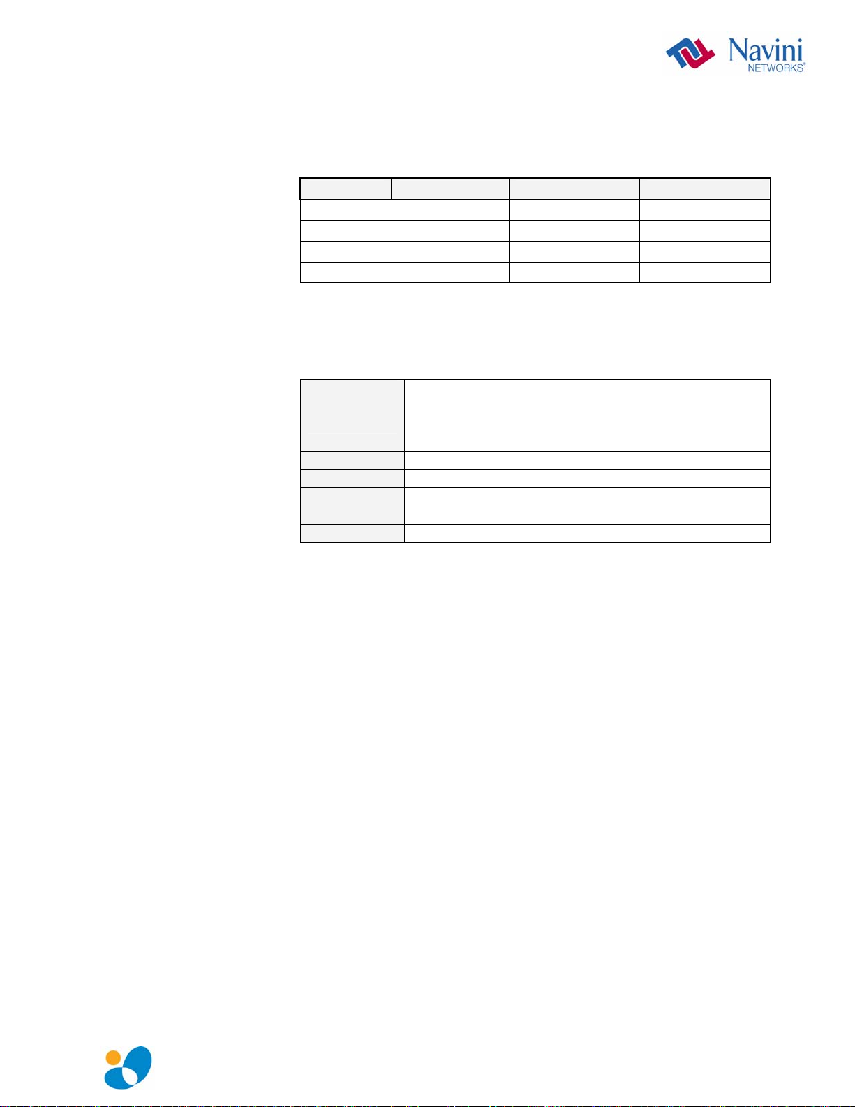
The PMX model indicates the frequency in which the PMX will
operate (for example, 3.4 GHz). The frequency number appears on
the PMX’s label. These are described in the table below.
Model Model Number Frequency Range Operating Band
2.3 GHz 2305-2360 PMX 2305-2360 MHz International Only
2.5-2.6 GHz 2.5-2.6 PMX 2500-2686 MHz EBS
3.4 GHz 3410-3525 PMX 3410-3525 MHz WLL
3.5 GHz 3475-3600 PMX 3475-3600 MHz WLL
The following table lists the minimum requirements your computer
must meet before using the PMX Card.
Operating
System
(OS)*:
CPU:
RAM:
Hard Drive:
Monitor:
Windows 2000, Windows XP, or Windows Vista32bits. It is assumed the latest Windows service pack
is installed on the Operating System. Note: The PMX
is not supported on MacIntosh or Linux/Unix systems.
Pentium level or higher
32 MB or the OS minimum, whichever is greater
85 MB free disk space for the optional Navini
Diagnostics* monitoring software
256 colors, 800 x 600 resolution
* If you are going to upgrade your Operating System after loading the Navini
Diagnostics software, you must first uninstall Navini Diagnostics prior to
upgrading the OS. Otherwise, the PMX will continue to operate, but the Navini
Diagnostics will not work. See Uninstall instructions in this Guide.
English_PMX_user_guide_2008_05_22_40-0460-00Rc(6.2.7).doc Page 8
Page 9

Physical
Characteristics
PMX Features
The PMX Card fits into a standard Type II PCMCIA slot. A 68-pin
connector on the end of the card connects it to the laptop.
68-pin connector
Two inverted-F antennas reside inside the PMX. All models also
have an external antenna.
Following is a picture of the external antenna in the upright
position. To raise the antenna to its upright position, raise the
antenna counterclockwise. Do not turn the antenna beyond its
upright position.
► Simple plug-and-play installation
► Indicator light showing power on and synchronization with a
Base Station
► Currently configured to use MC-SCDMA wireless technology
► Future models will run the OFDMA wireless technology
► OFDMA mode will meet IEEE 802.16e air interface standards
► Portable
► Works in Non Line of Sight (NLOS) conditions, using Smart
Beamforming technology
► Automated over-the-air software upgrades
► Manual procedure for the initial CDMA-to-WiMAX upgrade
► Optional accessory: Desktop Antenna
English_PMX_user_guide_2008_05_22_40-0460-00Rc(6.2.7).doc Page 9
Page 10

Installing the
PMX
The following instructions explain how to install the PMX and its
driver software on your computer. Please read all instructions
before attempting the installation.
Note: The laptop should be used preferably on a desk when
the Card is installed. Using the laptop with the Card close to the
body, such as on the lap, is undesirable.
Note: The screenshots shown in these instructions were taken
from a laptop operating with Windows XP. If you have a Windows
2000 or Vista operating system, the screens you see may vary from
the screens shown in the instructions.
Step Action Illustration
1. Insert the Card into the
Type II card slot on your
computer. Be sure to
insert the end that has
the 68-pin connector
into the card slot.
2. Raise the antenna to the
upright position.
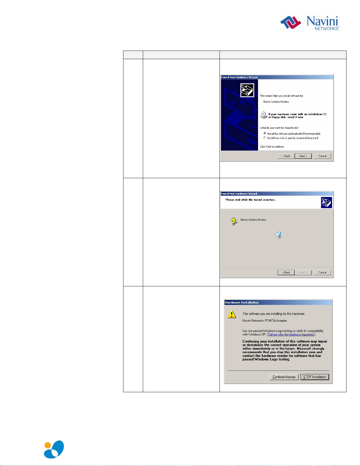
3. The Found New
Hardware message
appears indicating the
PC sees the Card.
4. The Welcome to the
Found New Hardware
Wizard dialog box
appears. Select “No, not
this time” and click
Next to continue.
English_PMX_user_guide_2008_05_22_40-0460-00Rc(6.2.7).doc Page 10
Page 11
Installing the PMX,
continued
Step Action Illustration
5. Insert the CD that came
with the card in the CD-
ROM drive. Click Next
to continue.
6. The Wizard searches for
the driver.
7. The Hardware
Installation box appears.
Click Continue
Anyway to install the
driver.
English_PMX_user_guide_2008_05_22_40-0460-00Rc(6.2.7).doc Page 11
Page 12

Installing the PMX,
continued
Step Action Illustration
8.
The driver is installed.
9. After the files are
copied, a Completing
the Found New
Hardware Wizard box
appears indicating the
driver installation is
complete. Click Finish
to close the Wizard.
10. A message is displayed
indicating that the new
hardware is installed and
ready to use.
English_PMX_user_guide_2008_05_22_40-0460-00Rc(6.2.7).doc Page 12
Page 13

Accessing the
Internet
Removing the
PMX
Now that your PMX is installed and your computer is on, you
should be able to access the Internet (that is, assuming you have
signed up with a Service Provider). To access the Internet, open the
web browser that is installed on your computer, (for example,
Netscape, Internet Explorer, etc.).
Before you store your PMX in a computer case, you should remove
the Card from the PC. Also, turn the antenna to its original down
position. Leaving the Card in the PC or the antenna in the upright
position while storing the PC in a computer case may damage the
card or the antenna.
To properly remove the PMX from your computer, you must first
stop the driver software. If you do not stop the driver software first,
the following box may appear:
To safely remove the PMX, click on the icon indicated in the
following illustration. Depending on your computer’s setup, this
icon is probably located in the lower right-hand corner of your
computer.
English_PMX_user_guide_2008_05_22_40-0460-00Rc(6.2.7).doc Page 13
Page 14

Indicator Light
Troubleshooting
An indicator light on the top of the PMX’s black encasement
provides information about the PMX’s operation. When the light
blinks, the PMX is trying to synchronize with a Base Station
(BTS). When the light is solid, the PMX has acquired
synchronization with a Base Station.
Indicator Light
If you experience difficulties with your Internet connection after
you have installed the PMX driver software, please review the
Minimum Computing Requirements and Addendum 2. Ensure your
computer meets those requirements. Also, review the installation
procedures and ensure all steps were completed properly. If you are
still experiencing difficulties, troubleshoot using the Navini
Diagnostics (NavDiag) monitoring software or contact your
Service Provider.
English_PMX_user_guide_2008_05_22_40-0460-00Rc(6.2.7).doc Page 14
Page 15
Installing Navini
Diagnostics
(NavDiag)
The NavDiag software assists you in solving connection problems
and provides other valuable information. This software is provided
on the Installation CD that came in your Card package. This
section explains how to install this software.
Note: To install NavDiag on a Windows 2000, you must have
administrative privileges. To check your account privileges, open
your Control Panel. Double-click on the Users and Passwords
symbol. You should see Administrator under the Users tab.
Note: The screenshots shown in the instructions were taken
from a laptop with Windows XP. If you have a Windows 2000 or
Vista operating system, the screens you see may vary from the
screens shown in the instructions.
Step Action Illustration
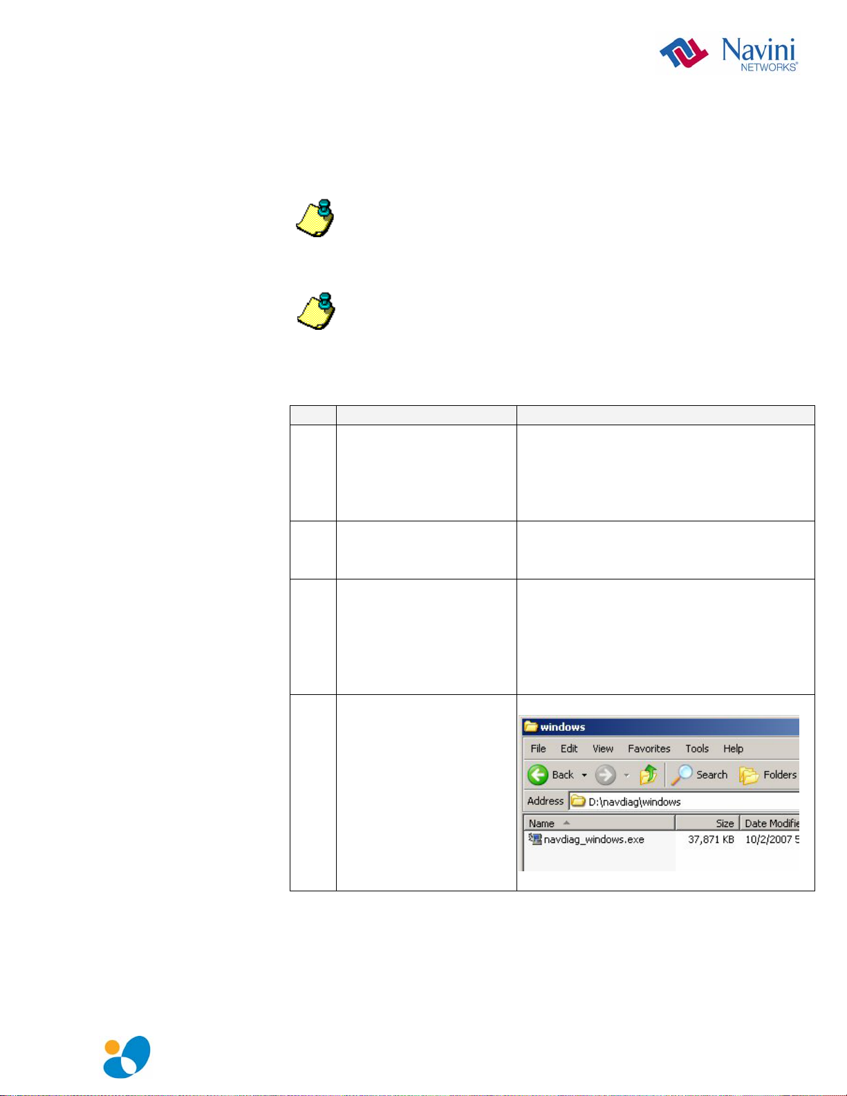
1. Before installing the
NavDiag software, shut
down all programs,
including anti-virus
software programs.
2. Insert the Installation
CD into the CD-ROM
drive.
3. Open the CD by clicking
on the My Computer
icon. Double-click on
the folder named
NavDiag or
Navini_Diagnostics.
4. Double-click on the
Windows folder, then
on the file
navdiag_windows.exe*.
This will automatically
start the installation of
NavDiag.
Example
English_PMX_user_guide_2008_05_22_40-0460-00Rc(6.2.7).doc Page 15
Page 16
Installing NavDiag,
•
continued
Step Action Illustration
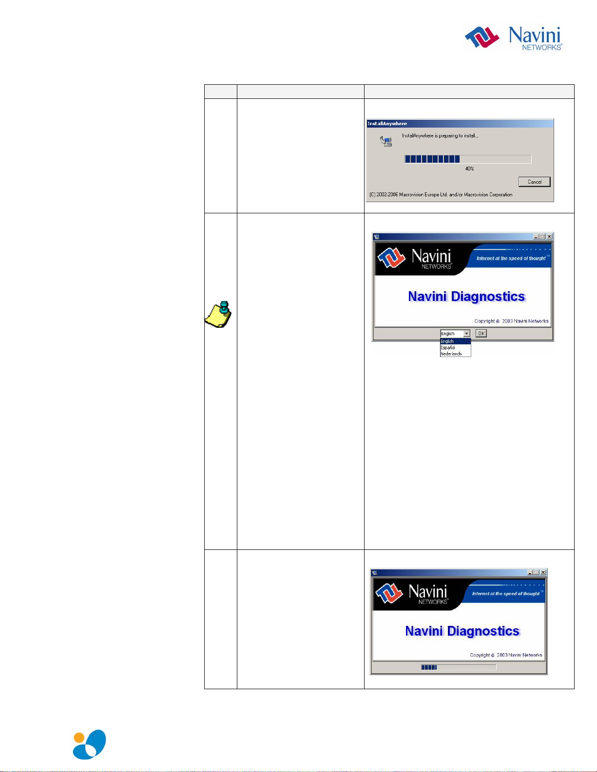
5. The InstallAnywhere
window appears. The
progress bar indicates
that InstallAnywhere has
initialized.
6. The Navini Diagnostics
Language screen
appears* (see Note
above). Select a
language, and click OK
to continue.
Note: NavDiag may
automatically attempt to
match the language set
on your PC under
Regional Options. The
language selection
affects how NavDiag
displays its screens. If
you receive an error
message concerning the
language, click OK and
NavDiag will default to
English. At this time,
NavDiag supports three
options:
1. English (U.S.),
2. Español (Spain), and
3. Nederlands (Holland).
7. The progress bar
indicates the files are
being installed.
English_PMX_user_guide_2008_05_22_40-0460-00Rc(6.2.7).doc Page 16
Page 17
Installing NavDiag,
continued
Step Action Illustration
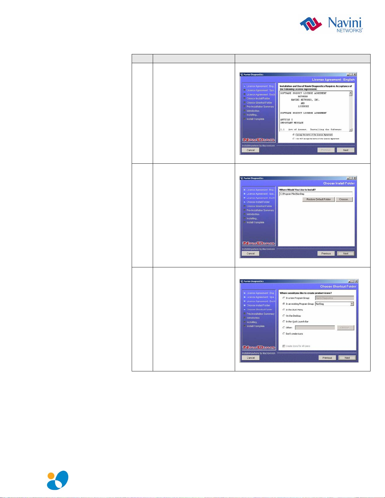
8. The License Agreement
screen appears. Read the
Licensing Agreement.
Select the I Accept
option, and click Next to
continue.
If the License
Agreement is not
accepted, you cannot
install the software.
9. The Choose Install
Folder screen appears.
Enter the name of the
folder where you wish to
install the software.
Click Next to continue.
The default installation
folder provided by the
software is shown in the
illustration.
10. The Choose Shortcut
Folder screen appears.
Accept the default and
click Next to continue.
English_PMX_user_guide_2008_05_22_40-0460-00Rc(6.2.7).doc Page 17
Page 18
Installing NavDiag,
continued
Step Action Illustration
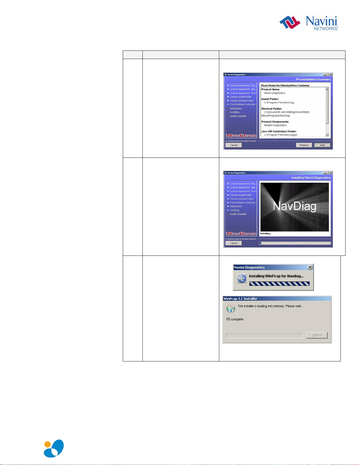
11. The Pre-Installation
Summary screen
appears. Review the
contents for accuracy.
Click Install to
continue.
For your installation and
computer, this screen
may have different
information than what is
shown in the illustration.
12. The Installing screen
will change as the
application files are
loaded.
13. If the WinPcap program
is already installed in
your computer, go to
step 16; otherwise, it
will be installed now
English_PMX_user_guide_2008_05_22_40-0460-00Rc(6.2.7).doc Page 18
Page 19

Installing NavDiag,
continued
Step Action Illustration
14. Continue with the
installation of the
WinPcap.
15. You must agree to the
License agreement to
continue with the Install.
16. At the Install Complete
screen, click Done to
close the window.
English_PMX_user_guide_2008_05_22_40-0460-00Rc(6.2.7).doc Page 19
Page 20
Troubleshooting
Using Navini
Diagnostics
The Icons
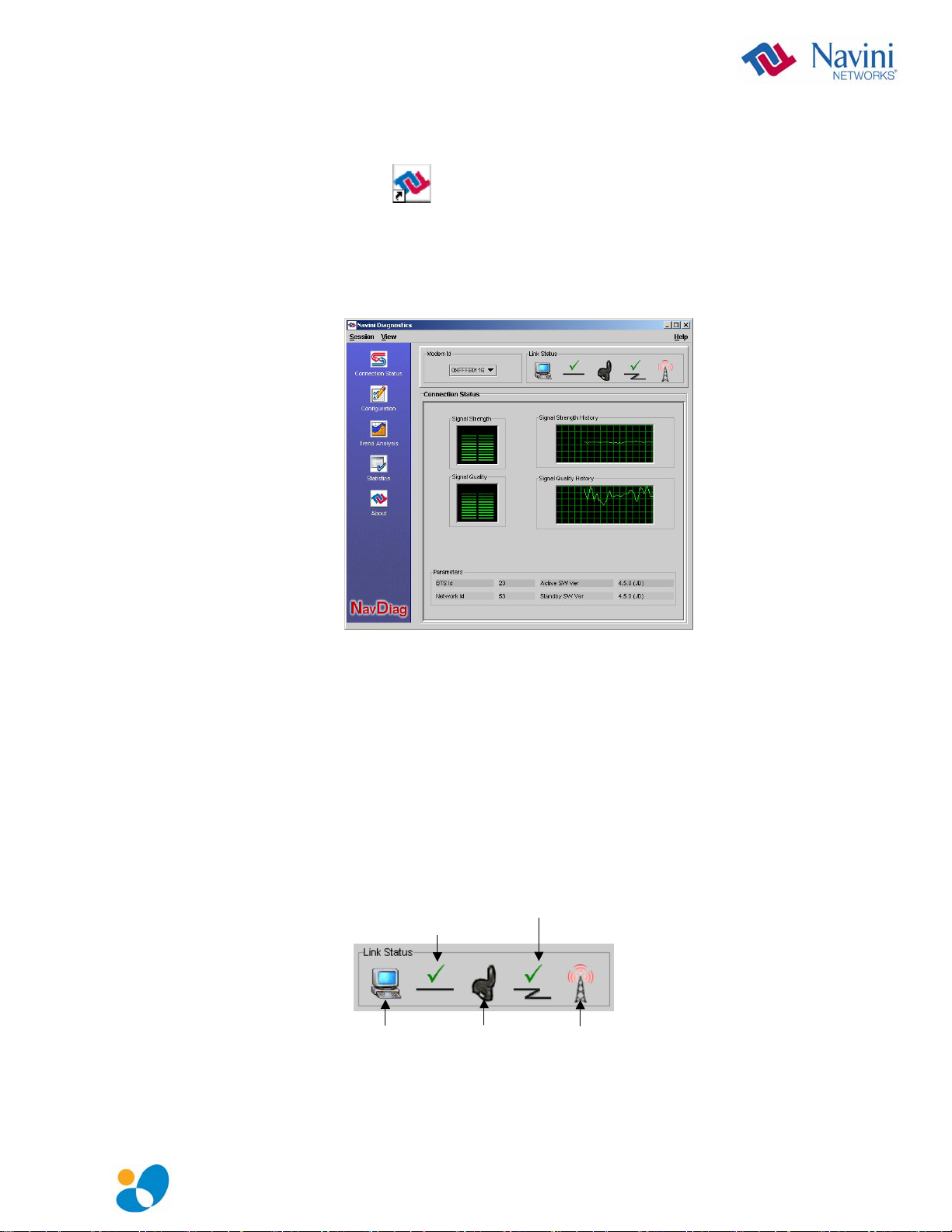
To open the Navini Diagnostics software application, double-click
on the Navini Diagnostics icon on your desktop.
Navini Diagnostics.lnk
The Connection Status screen will open and display data if the
Card is in use. The screen will refresh live data every second.
The following sections describe the various parts of the Connection
Status screen.
The icons that appear on the top right side of the screen represent
the PC, the connection between the PC and the Modem, the
Modem, the connection between the Modem and the Base Station,
and the Base Station to which the Modem is communicating.
Check marks over the connections indicate working connections.
Connection between
Connection between
Modem & Base Station
Connection between
Connection between
PC & Modem
PC & Modem
PC
PC
Modem & Base Station
Base Station
Modem
Modem
Base Station
English_PMX_user_guide_2008_05_22_40-0460-00Rc(6.2.7).doc Page 20
Page 21
The Icons, continued
The Signal
Strength and
Signal Quality Bars
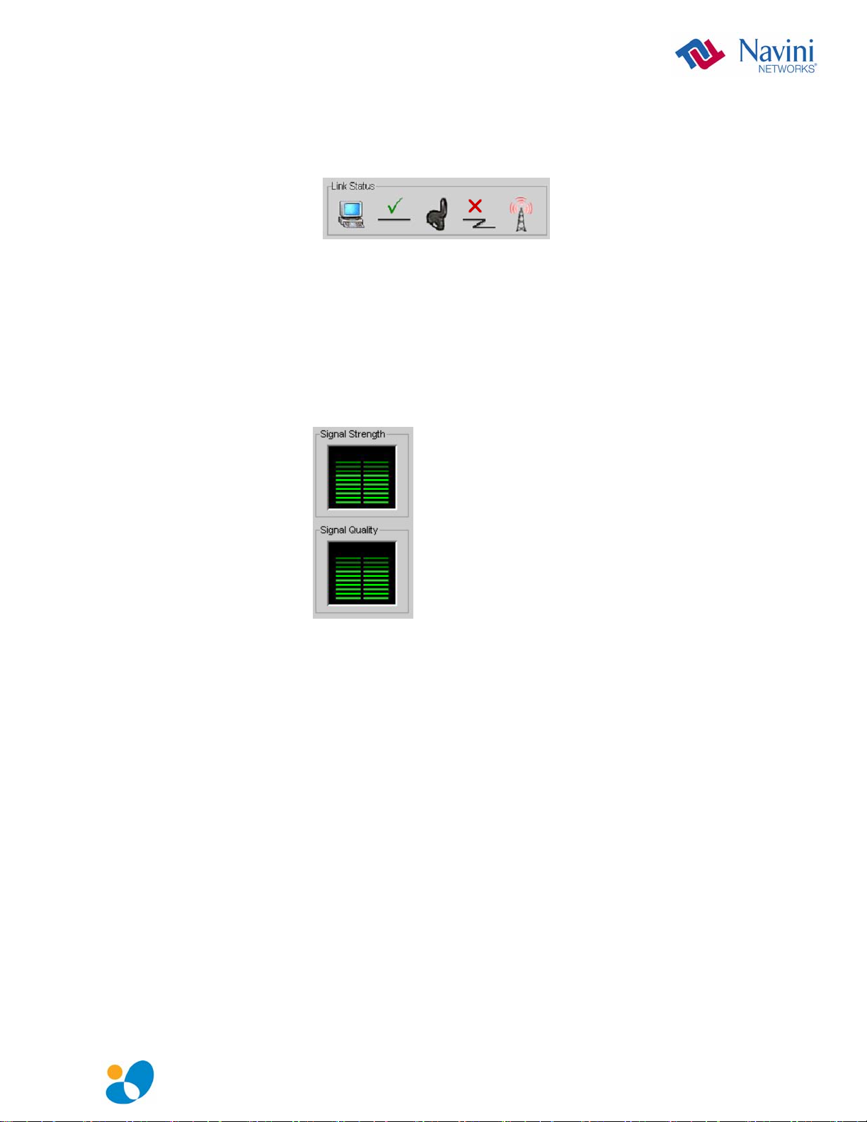
An “X” is positioned over the corresponding icon indicates the
connection between the PC and the Modem or between the Modem
and the Base Station is interrupted
If the connection between the PC and the Card or between the Card
and the Base Station is interrupted, an “X” is positioned over the
corresponding icon.
Signal Strength and Signal Quality are dynamic bar areas that
indicate how well your Card is receiving signals from the Base
Station.
In particular, the Signal Strength bar area graphically represents the
strength of the synchronization signal your Modem is receiving
from BTS. The strength of the signal is represented by a group of
colored bars. The higher the pile of bars goes, the stronger the
signal is. The color of the bars also gives an indication of the
strength of the signal. Green lines indicate an excellent signal.
Orange lines indicate a good signal while red lines indicate a weak
signal.
The Signal Quality bar area graphically represents the Signal-toNoise Ratio (SNR) received by your Modem. Again, the quality of
the signal is represented by a group of colored bars. The higher the
pile of bars goes, the better the SNR of the signal. The color of the
bars also gives an indication of the quality of the signal. Green
lines indicate an excellent signal or an SNR greater than 21.
Orange lines indicate a good signal or an SNR greater than or equal
to 13 but less than or equal to 21. Red lines indicate a weak signal
or an SNR less than 13.
English_PMX_user_guide_2008_05_22_40-0460-00Rc(6.2.7).doc Page 21
Page 22

How to Increase the
Strength and Quality
of the Signal
The History Graphs
The Parameters
To increase the strength and quality of the signal, change the
location of the PC in which the Card is inserted. Try moving it
closer to a window, to a higher location, away from other wireless
devices (microwave ovens, cordless phones), and away from metal
objects (shelves, file cabinets). As you reposition your PC, watch
the Signal Strength and Quality bars on the NavDiag screen. Place
your PC in the location where you receive the most green signal
strength and quality bars.
The History graphs plot the change in signal strength and signal
quality over time. The graphs cover the last minute and are updated
every second. Read the graphs from right to left. The right side of
the graph represents the most recent status of your Card.
At the bottom of the Connection Status screen are four parameters.
These parameters are BTS ID, Network ID, Active SW Version,
and Standby SW Version.
The BTS ID indicates the BTS to which the Card is currently
synchronized. The Network ID indicates the network in which the
Card is operating. Active SW Version and Standby SW Version
English_PMX_user_guide_2008_05_22_40-0460-00Rc(6.2.7).doc Page 22
Page 23

The Parameters, continued
The Screen Option
Buttons
The Configuration
Screen
The Trend Analysis
Screen
indicate the version number of the software currently loaded in the
“active side” and “standby side” of the Card’s flash memory. The
two letters in parenthesis following the release number indicate the
type of software load. JD indicates Joint Detection while EN
indicates Enhanced Nulling.
On the left-hand side of the screen, there are five screen option
buttons: Connection Status, Configuration, Trend Analysis,
Statistics, and About. Each of these screens provides unique
capabilities.
The Configuration screen enables you to update your Card’s
software if directed to do so by your Service Provider. To access
the Configuration screen, press the Configuration button.
If you must update your Card’s software, your Service Provider
will provide you with instructions regarding what to do.
At the bottom of the screen is an Allow Customer Satisfaction
Reporting box. This box currently is not supported on the Card.
The Trend Analysis screen lets you view Card parameters that
evolve over time. With this screen, you can select up to three
parameters to plot. To view the Trend Analysis screen, press the
Trend Analysis button.
English_PMX_user_guide_2008_05_22_40-0460-00Rc(6.2.7).doc Page 23
Page 24

The Trend Analysis
Screen, continued
The Statistics
Screen
By selecting one or more parameters and then pressing the Plot
Graph button, the following screen appears. This screen displays
the value of the selected parameters over the last five minutes,
updated once every second. The graphic scrolls from right to left.
The Statistics screen lets you view the current value of selected
parameters. These values are updated as they change over time. To
view the Statistics screen, press the Statistics button.
English_PMX_user_guide_2008_05_22_40-0460-00Rc(6.2.7).doc Page 24
Page 25

The About Screen
The Help Button
The About screen provides vital information such as the version of
the Navini Diagnostics software currently installed on your
computer. It also provides a website address and telephone number
where you can contact your Service Provider. To view the About
screen, press the About button.
A Help button appears on the top right corner of all the NavDiag
windows. The Help button gives you two options. The first option,
On NavDiag, provides help text on the functionality of the
NavDiag program. The second option, About NavDiag, is
equivalent to clicking on the About icon.
English_PMX_user_guide_2008_05_22_40-0460-00Rc(6.2.7).doc Page 25
 Loading...