

Page 1
Doc. No.
78-4144-01
Installing Cisco AC and DC Power Supplies in
Cisco 2500 Series Routers
Product Numbers: PWR-2500-AC=, PWR-2500-DC=
This document describes how to replace the AC or DC power supply in Cisco 2500 series routers.
The AC and DC power supplies are spare parts items. The replacement of the po wer supply requires
removing the existing power supply and installing the replacement power supply. This procedure
does not apply to the Cisco 2517, 2518, or 2519 versions of the Cisco 2500 series routers.
This document includes the following sections:
• Required Tools and Equipment, page 2
Corporate Headquarters
Cisco Systems, Inc.
170 West Tasman Drive
San Jose, CA 95134-1706
USA
Copyright © 1997
Cisco Systems, Inc.
All rights reserved.
• Removing the Cover, page 2
• Removing AC and DC Power Supplies, page 3
• Installing AC and DC Power Supplies, page 5
• Replacing the Cover, page 6
• Obtaining Service and Support, page 11
• Cisco Connection Online, page 11
Warning This waning symbol means danger. You are in a situation that could cause bodily injury.
Before you work on any equipment, you must be aware of the hazards involved with the electrical
circuitry and familiar with standard practices for preventing accidents. (To see translated versions of
this warning, refer to the Regulatory Compliance and Safety Information document that
accompanied the router.)
Warning Only trained and qualified personnel should be allowed to install or replace this
equipment. (To see translated versions of this warning, refer to the Regulatory Compliance and
Safety Information document that accompanied the router.)
1
Page 2

Required Tools and Equipment
Warning Read the installation instructions before you connect the system to its power source. (To
see translated versions of this warning, refer to the Regulatory Compliance and Safety Information
document that accompanied the router.)
Required Tools and Equipment
You will need the following items:
• One screw
• Cisco 2500 series router
• AC or DC power supply
• Medium-size flat-blade screwdriver
• ESD-preventive wrist strap
• Antistatic bag
Removing the Cover
You must remove the chassis cover to access the internal power supply. When opening the chassis,
refer to Parts A and B in Figure 1.
Warning Before opening the chassis, disconnect the telephone-network cables to avoid contact
with telephone-network voltages. (T o see translated v ersions of this warning, refer to theRegulatory
Compliance and Safety Information document that accompanied the router.)
Warning Before working on equipment that is connected to po wer lines, remove jewelry (including
rings, necklaces, and watches). Metal objects will heat up when connected to power and ground and
can cause serious burns or weld the metal object to the terminals. (To see translated versions of this
warning, refer to theRegulatory Compliance and Safety Informationdocument that accompanied the
router.)
Warning Before working on a chassis or working near power supplies, unplug the power cord on
AC units; disconnect the power at the circuit break er on DC units. (To see translated versions of this
warning, refer to theRegulatory Compliance and Safety Informationdocument that accompanied the
router.)
Warning Do not work on the system or connect or disconnect cables during periods of lightning
activity. (To see translated versions of this warning, refer to the Regulatory Compliance and Safety
Information document that accompanied the router.)
Take the following steps to remove the chassis cover:
Step 1 Power OFF the router.
Step 2 Attach your ESD-preventive wrist strap.
Step 3 Disconnect all cables from the rear panel of the router.
2 Installing Cisco AC and DC Power Supplies in Cisco 2500 Series Routers
Page 3

Removing AC and DC Power Supplies
Warning Do not touch the power supply when the power cord is connected. For systems with a
power switch, line voltages are present within the po wer supply ev en when the power switch is OFF
and the power cord is connected. For systems without a power switch, line voltages are present
within the power supply when the power cord is connected. (To see translated versions of this
warning, refer to theRegulatory Compliance and Safety Information document that accompanied the
router.)
Step 4 Turn the unit upside do wn so that the top of the chassis is resting on a flat surface, and the
front of the chassis is facing toward you. (See Figure 1, Part A.)
Step 5 Remove the single screw located on the bottom of the chassis (on the side closest to you).
Note that the chassis is comprised of two sections: top and bottom.
Step 6 If required, insert a medium-size flat-blade screwdriver into the slots shown in Figure 1,
Part A, and rotate the blade so that the top and bottom sections separate slightly.
Step 7 Holding the chassis with both hands, position it as shown in Figure 1, Part B.
Step 8 Pull the top section away from the bottom section. (See Figure 1, Part B.) The fit is very
snug, so it may be necessary to pry the chassis sections apart at one end and then the other
until they separate.
Figure 1 Chassis Cover Removal
A
Slot
B
Flat-blade screwdriver
Screw Slot
Removing AC and DC Power Supplies
This section describes how to remove an AC or DC power supply. Although an AC power supply is
shown in the illustrations that follow , the procedure is the same for removing both A C and DC power
supplies.
Top section
Bottom section
Left end
toward you
H7824
H3557
FrontRear
Take the following steps to remove a power supply:
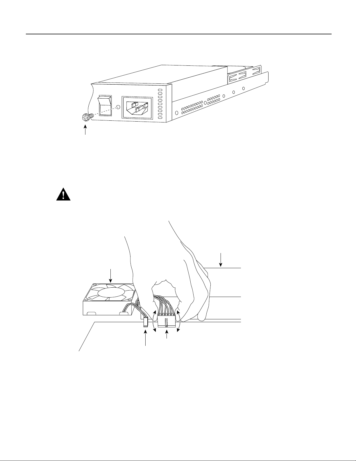
Step 1 Remove the screw located between the power switch and power connector.
(See Figure 2.) This screw secures the power supply to the chassis.
Installing Cisco AC and DC Power Supplies in Cisco 2500 Series Routers 3
Page 4
Removing AC and DC Power Supplies
Figure 2 Removing the Screw
1
0
Screw
Input: 100-240VAC
Freq: 50/60 Hz
Current: 1.2-0.6A
Watts: 40W
H9079
Step 2
Disconnect the power connector from the system board. (See Figure 3.) Grasp the sides
of the power connector and pull upward while rocking the connector side to side.
Caution Do not pull on the connector wires.
Figure 3 Disconnecting the Power Connector
Fan
AC power supply
Power connector
Fan connector
Step 3
Push the loosened power supply backward and lift it out of the chassis. (See Figure 4.)
4 Installing Cisco AC and DC Power Supplies in Cisco 2500 Series Routers
H9081
Page 5

Figure 4 Removing the Power Supply
AC power supply Fan
Installing AC and DC Power Supplies
H9082
Step 4
Place the removed screw and power supply in an antistatic bag.
Installing AC and DC Power Supplies
This section describes how to install AC and DC power supplies. Although an AC power supply is
shown in the illustrations that follow , the procedure is the same for installing both A C and DC po wer
supplies.
Step 1 Put the power supply into place and gently slide it toward the back of the chassis engaging
the tabs on the bottom of the case with the slots in the bottom of the power supply.
(See Figure 5.)
Figure 5 Inserting the Power Supply
Token Ring Switch Token Ring Switch
10 23456789
Stations
Token Ring Switch Token Ring Switch
10 23456789
Stations
Patch
cables
Lobe
cables
10 23456789
Stations
10 23456789
Stations
H9632
Step 2
Install the screw that came with the Cisco power supply into the screw hole between the
power switch and power connector. (See Figure 6.)
Installing Cisco AC and DC Power Supplies in Cisco 2500 Series Routers 5
Page 6

Replacing the Cover
Figure 6 Installing the Screw
Input: 100-240VAC
Freq: 50/60 Hz
Current: 1.2-0.6A
Watts: 40W
1
0
Screw
Step 3
Connect the power connector from the system board. Grasp the sides of the power
connector and gently push downward while rocking the connector side to side.
(See Figure 7.)
Figure 7 Connecting the Power Connector
H9079
Replacing the Cover
Take the following steps to replace the cover:
Step 1 Position the two chassis sections, as shown in Figure 8.
Step 2 Referring to Figure 8, press the two chassis sections together and ensure the following:
AC power supply
Fan
H9247
Power connector
Fan connector
• The top section fits into the rear of the bottom section. (See A in Figure 8.)
• The bottom section fits into the front of the top section. (See B in Figure 8.)
• Each side of the top and bottom sections fits together. (See C in Figure 8.)
6 Installing Cisco AC and DC Power Supplies in Cisco 2500 Series Routers
Page 7

Replacing the Cover
Caution T o fit the two sections together , it may be necessary to w ork them together at one end and
then the other, working back and forth; ho wever, use care to pre v ent bending the chassis edges. (To
see translated versions of this warning, refer to the Regulatory Compliance and Safety Information
document that accompanied the router.)
Figure 8 Replacing the Chassis Cover
Step 3
A
Top section
Bottom section
Left end
toward you
When the two sections fit together snugly , turn the chassis so that the bottom is facing up,
C
B
FrontRear
with the front panel toward you.
Step 4 Replace the cover screw. (See Figure 8.)
Step 5 Remove the protective cover from the back of the power requirements label.
Step 6 Carefully place the label directly over the silk screened power requirements information
on the rear panel of the system.
Step 7 Remove the protective cover from the back of the system designation label.
Step 8 Carefully place the label directly over the silk screened system designation information
on the rear panel of the system.
Step 9 Reinstall the chassis on the wall, rack, desktop, or table.
H3560
Step 10 Replace all cables.
Step 11 Remove your ESD-preventive wrist strap.
Note Ensure that the System OK LED is not covered by the system designation label.
This completes the procedure for installing AC and DC power supplies. If you have questions or
need assistance, see the section “Obtaining Service and Support.”
Installing Cisco AC and DC Power Supplies in Cisco 2500 Series Routers 7
Page 8

Connecting the DC Power Supply
Connecting the DC Power Supply
This section describes the DC power supply specifications and wiring.
Warning This unit is intended for installation in restricted access areas. A restricted access area is where access
can only be gained by service personnel through the use of a special tool, lock and key , or other means of security ,
and is controlled by the authority responsible for the location. (T o see translated v ersions of the warning, refer to
the Regulatory Compliance and Safety Information document that accompanied your router.)
DC Power Specifications
The DC power supply is intended for use in DC operating environments. Table 1 lists the power supply
specifications.
Table 1 DC Power Supply Specifications
Design
Description
Power (input) 40W, –40 to –72 VDC
Wire gauge for power connections 14 AWG
1. AWG = American Wire Gauge.
Specification
1
Wiring the DC Power Supply
Follow the directions in this section to wire the terminal block.
Warning Before performing any of the follo wing procedures, ensure that power is remo ved from the DC circuit.
To ensure that all power is OFF, locate the circuit breaker on the panel board that services the DC circuit, switch
the circuit breaker to the OFF position, and tape the switch handle of the circuit breaker in the OFF position. (To
see translated versions of this warning, refer to the Regulatory Compliance and Safety Information document that
accompanied your router.)
Note This product is intended for installation in restricted access areas and is approved for use with
14 AWG copper conductors only. The installation must comply with all applicable codes.
Take the following steps to wire the terminal block:
Step 1 Attach the appropriate lugs at the wire end of the power supply cord.
Step 2 Wire the DC power supply to the terminal block, as shown in Figure 9.
Warning The illustration shows the DC power supply terminal block. Wire the DC power supply using the
appropriate lugs at the wiring end, as illustrated. The proper wiring sequence is ground to ground, positive to
positive (line to L), and negati ve to ne gativ e (neutral to N). Note that the ground wire should always be connected
first and disconnected last. (To see translated versions of this warning, refer to the Regulatory Compliance and
Safety Information document that accompanied your router.)
8 Installing Cisco AC and DC Power Supplies in Cisco 2500 Series Routers
Page 9

Figure 9 DC Power Supply Connections
Negative
Connecting the DC Power Supply
Ground
Terminal block
Positive
On/off
Terminal block
H7253
Warning When stranded wiring is required, use approved wiring terminations, such as closed-loop or spade-type
with upturned lugs. These terminations should be the appropriate size for the wires and should clamp both the
insulation and conductor. (To see translated versions of this warning, refer to the Regulatory Compliance and
Safety Information document that accompanied your router.)
Caution Do not overtorque the terminal block captive thumbscrew or terminal block contact screws. The
recommended torque is 8.2 0.4 inch-lb.
Warning After wiring the DC power supply, remove the tape from the circuit breaker switch handle and reinstate
power by moving the handle of the circuit breaker to the ON position. (To see translated versions of this warning,
refer to the Regulatory Compliance and Safety Information document that accompanied your router.
Installing Cisco AC and DC Power Supplies in Cisco 2500 Series Routers 9
Page 10

Connecting the DC Power Supply
Warning This product relies on the building’ s installation for short-circuit (ov ercurrent) protection.
Ensure that a fuse or circuit breaker no larger than 120 V AC, 15A U.S. (240 V AC, 10A international)
is used on the phase conductors (all current-carrying conductors). (T o see translated versions of this
warning, refer to theRegulatory Compliance and Safety Informationdocument that accompanied the
router.)
Warning This equipment is intended to be grounded. Ensure that the host is connected to earth
ground during normal use. (To see translated versions of this warning, refer to the Regulatory
Compliance and Safety Information document that accompanied the router.)
Installing Power Requirements and System Identifier Labels
Follow the directions in this section to place the Power Requirements and System Identifier labels
on the rear panel of the Cisco 2500 series routers.
Note The steps in this section are only performed when the router is being converted from an AC
power supply to a DC power supply.
Step 1 Remove the Power Requirements label from the sheet of labels included with the po wer
supply. (See Figure 10.)
Figure 10 Power Requirements and System Identifier Label Sheet
Cisco 2501-DC Cisco 2503-DC Cisco 2504-DC Cisco 2505-DC Cisco 2507-DC
Cisco 2509-DC Cisco 2511-DC Cisco 2514-DC Cisco 2515-DC
Cisco
Cisco
Cisco
Cisco
2520-DC
2521-DC
Input: 40-72 V
Current: 1.5 4.0 A
Volts: 40 V
2522-DC
2523-DC
Cisco
2524-DC
H9739
Note If the power supply in the Cisco 2500 series router is being conv erted from DC to AC, simply
remove the Power Requirements and System Identifier labels from the rear panel of the router
chassis.
Step 2 Place the label directly over the silk screened power requirements on the rear panel of the
Cisco 2500 series router. (See Figure 11)
10 Installing Cisco AC and DC Power Supplies in Cisco 2500 Series Routers
Page 11

Figure 11 Rear Panel Label Locations
Obtaining Service and Support
System identifier
label
Cisco
2520 DC
Power requirements
Input 40 – 72 V
Current 1.5 – 1.0 A
Watts 40 W
1
0
label
H9688
Note The System Identifier label shown in Figure 11 shows the Cisco 2520 DC system label for
demonstration purposes. Place the appropriate label for your specific model of Cisco 2500 series
router in place of this label.
Step 3 Remove the System Identifier label from the sheet of labels included with the power
supply. (See Figure 10)
Step 4 Place the System Identifier label directly to the left of the on/off power switch on the rear
panel of the Cisco 2500 series router. (See Figure 11)
Obtaining Service and Support
For service and support for a product purchased from a reseller, contact the reseller. Resellers offer
a wide variety of Cisco service and support programs, which are described in the section “Service
and Support” in the information packet that shipped with your chassis.
Note If you purchased your product from a reseller, you can access Cisco Connection Online
(CCO) as a guest. CCO is Cisco Systems’ primary, real-time support channel. Your reseller offers
programs that include direct access to CCO’s services.
For service and support for a product purchased directly from Cisco, use CCO.
Cisco Connection Online
CCO is Cisco Systems’ primary, real-time support channel. SMARTnet customers and partners can
self-register on CCO to obtain additional information and services.
Note If you purchased your product from a reseller, you can access CCO as a guest. Your reseller
offers programs that include direct access to CCO’s services.
Installing Cisco AC and DC Power Supplies in Cisco 2500 Series Routers 11
Page 12

Cisco Connection Online
Available 24 hours a day, 7 days a week, CCO provides a wealth of standard and value-added
services to Cisco’s customers and business partners. CCO services include product information,
product documentation, software updates, release notes, technical tips, the Bug Navigator,
configuration notes, brochures, descriptions of service offerings, and download access to public and
authorized files.
CCO serves a wide variety of users through two interfaces that are updated and enhanced
simultaneously: a character-based version and a multimedia version that resides on the World Wide
Web (WWW). The character-based CCO supports Zmodem, Kermit, Xmodem, FTP, and Internet
e-mail, and it is excellent for quick access to information over lower bandwidths. The WWW v ersion
of CCO provides richly formatted documents with photographs, figures, graphics, and video, as well
as hyperlinks to related information.
You can access CCO in the following ways:
• WWW: http://www.cisco.com
• WWW: http://www-europe.cisco.com
• WWW: http://www-china.cisco.com
• Telnet: cco.cisco.com
• Modem: From North America, 408 526-8070; from Europe, 33 1 64 46 40 82. Use the
following terminal settings: VT100 emulation; databits: 8; parity: none; stop bits: 1; and
connection rates up to 28.8 kbps.
For a copy of CCO’s Frequently Asked Questions (FAQ), contact cco-help@cisco.com. For
additional information, contact cco-team@cisco.com.
Note If you need technical assistance with a Cisco product that is under warranty or covered by a
Cisco maintenance contract, contact Cisco’s Technical Assistance Center (TAC) at 800 553-2447,
408 526-7209, or tac@cisco.com.
Please use CCO to obtain general information about Cisco Systems, Cisco products, or upgrades. If
CCO is not accessible, contact 800 553-6387, 408 526-7208, or cs-rep@cisco.com.
Use this document with your Cisco 2500 series router Installation and Configuration Guide and the Regulatory Compliance and Safety Information publications.
AtmDirector, AutoConnect, AutoRoute, AXIS, BPX, Catalyst, CD-PAC, CiscoAdvantage, CiscoFusion, Cisco IOS, the Cisco IOS logo,CiscoLink, CiscoPro, the CiscoPro logo,
CiscoRemote, the CiscoRemote logo, CiscoSecure, Cisco Systems, CiscoView, CiscoVision, CiscoWorks, ClickStart, ControlStream, EdgeConnect, EtherChannel, FairShare, FastCell,
FastForward, FastManager, FastMate, FastPADlmp, FastPADmicro, FastPADmp, FragmentFree, FrameClass, Fulcrum INS, IGX, Impact, InternetJunction, JumpStart, LAN
Enterprise, LAN
SMARTnet, StrataSphere, StrataSphere BILLder , StrataSphere Connection Manager, StrataSphere Modeler, StrataSphere Optimizer, Stratm, StrataView Plus, StreamView , SwitchProbe,
SwitchVision, SwitchWare, SynchroniCD, The Cell, The FastPacket Company, TokenSwitch, TrafficDirector, Virtual EtherSwitch, VirtualStream, VlanDirector, Web Clusters, WNIC,
Workgroup Director, Workgroup Stack, and XCI are trademarks; Access by Cisco, Bringing the Power of Internetworking to Everyone, Enter the Net with MultiNet, and The Network
Works. NoExcuses. are service marks; and Cisco, the Cisco Systems logo, CollisionFree, Combinet, EtherSwitch, FastHub, FastLink, FastNIC, FastPacket, FastPAD, FastSwitch,
ForeSight, Grand, Grand Junction, Grand Junction Networks, the Grand Junction Networks logo, HSSI, IGRP, IPX, Kalpana, the Kalpana logo, LightStream, MultiNet, MultiWare,
OptiClass, Personal Ethernet, Phase/IP, RPS, StrataCom, TGV, the TGV logo, and UniverCD are registered trademarks of Cisco Systems, Inc. All other trademarks, service marks,
registered trademarks, or registered service marks mentioned in this document are the property of their respective owners.
Copyright © 1997, Cisco Systems, Inc.
All rights reserved. Printed in USA.
9611R
2
LAN Remote Office, LightSwitch, MICA, NetBeyond, NetFlow, Newport Systems Solutions, Packet, PIX, Point and Click Internetworking, RouteStream, Secure/IP,
2
LAN
12 Installing Cisco AC and DC Power Supplies in Cisco 2500 Series Routers
 Loading...