

Page 1
Chapter 6 Installation
PRELIMINARY
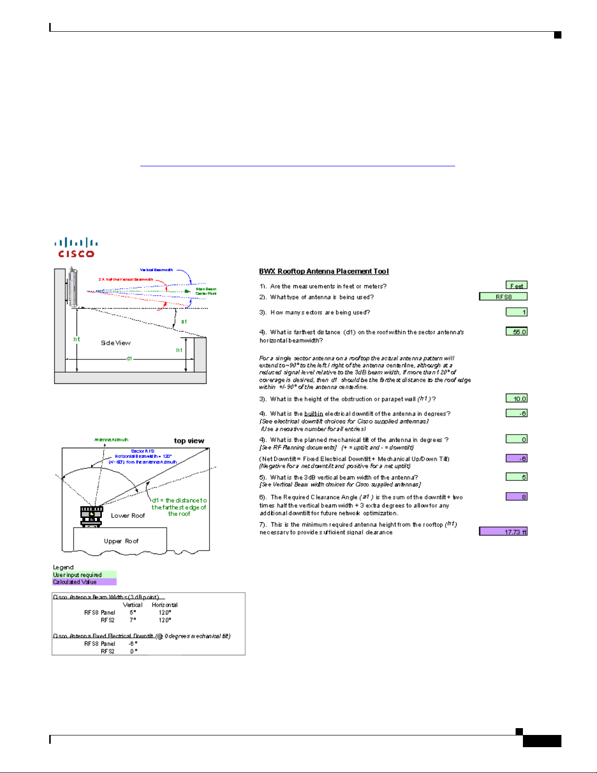
6.3.6 Rooftop Antenna Placement Tool
Reference: Rooftop Antenna Placement Tool
This is a picture of the worksheet in the Antenna Placement Tool for a quick visual identification
Figure 6-17); this appendix does not include the entire tool. Please use the electronic copy of the tool to
datafill the site information. This form can be found on the following LiveLink site:
https://tools.cisco.com/cws/livelink?func=ll&objid=4353291&objaction=browse
The Tool is updated periodically. If you are not sure that you have the latest version, please contact Cisco
Technical Services and request that the latest version of the tool be sent to you.
Figure 6-17 Rooftop Antenna Placement Tool
6.3.6 Rooftop Antenna Placement Tool
OL-19519-01
BWX 8415 Basestation Installation and Commissioning Guide
6-17
Page 2
6.3.7 Set the Downtilt
6.3.7 Set the Downtilt
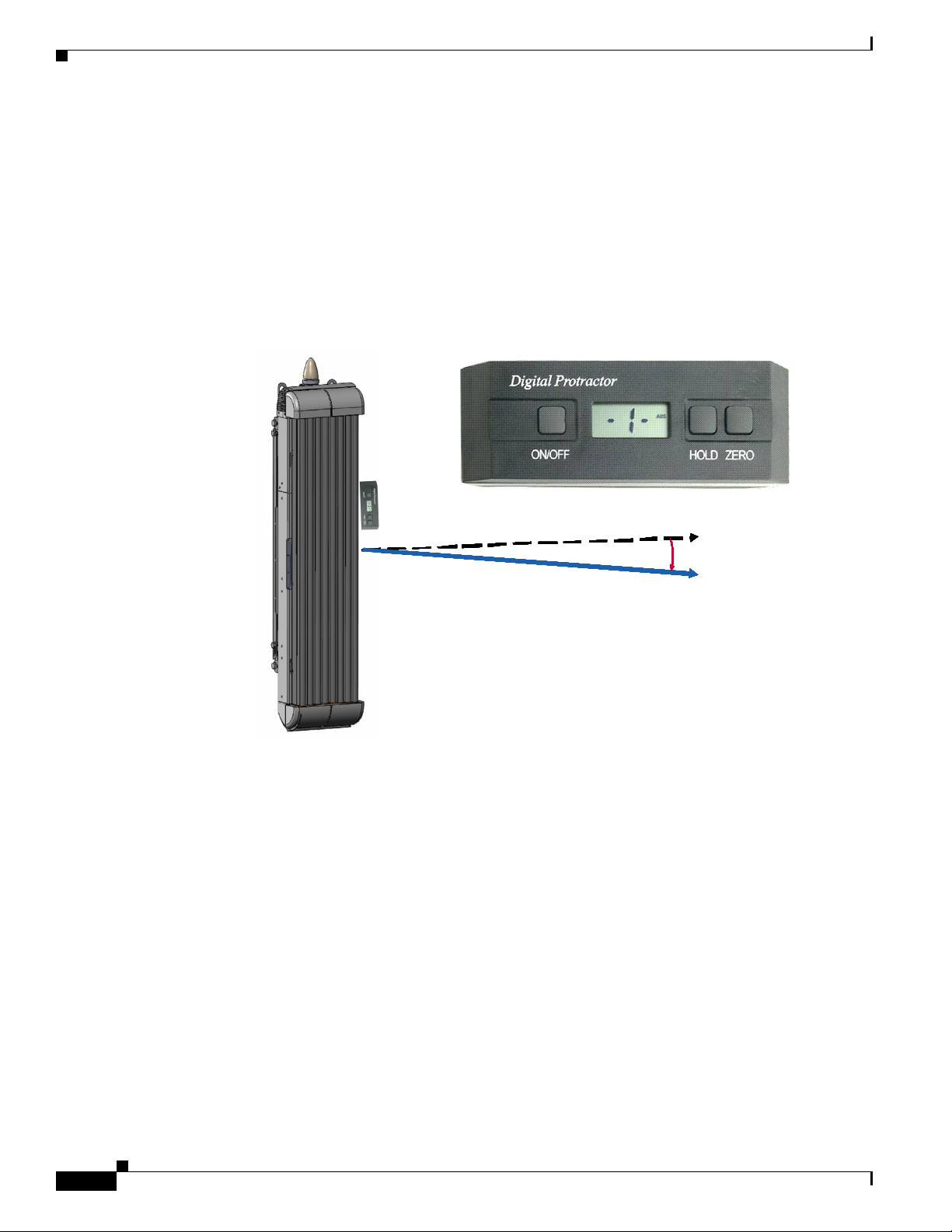
Based on coverage objectives determined by previous RF planning, the AU may need adjusting upward
or downward once mounted on the pole, tower, roof, building, or other structure. The panel antenna has
a -6° built-in electrical downtilt.
You will use an inclinometer to read the mounted position and to determine what adjustments, if any,
need to be made. For example, if the inclinometer reads +2° (uptilt) and you are mounting an AU, the
resulting beam has a –4° downtilt (
Figure 6-18 Downtilt Adjustment Example
Chapter 6 Installation
PRELIMINARY
Figure 6-18).
t
t
t
t
t
t
t
t
t
t
t
t
n
n
n
n
n
n
n
n
n
n
n
n
e
e
e
e
e
e
e
e
e
e
e
e
r
r
r
r
r
r
r
r
r
r
r
r
a
a
a
a
a
a
a
a
a
a
a
a
p
p
p
p
p
p
p
p
p
p
p
p
p
p
p
p
p
p
p
p
p
p
p
p
A
A
A
A
A
A
A
A
A
A
A
A
E
E
E
E
E
E
E
E
E
E
E
E
f
f
f
f
f
f
f
f
f
f
f
f
f
f
f
f
f
f
f
f
f
f
f
f
e
e
e
e
e
e
e
e
e
e
e
e
c
c
c
c
c
c
c
c
c
c
c
c
t
t
t
t
t
t
t
t
t
t
t
t
i
i
i
i
i
i
i
i
i
i
i
i
v
v
v
v
v
v
v
v
v
v
v
v
e
e
e
e
e
e
e
e
e
e
e
e
The inclinometer reads +1 ° (uptilt)
The inclinometer reads +1 ° (uptilt)
The panel antenna has a -6 ° built in
The panel antenna has a -6 ° built in
electrical downtilt
electrical downtilt
The resulting beam has a -5
The resulting beam has a -5
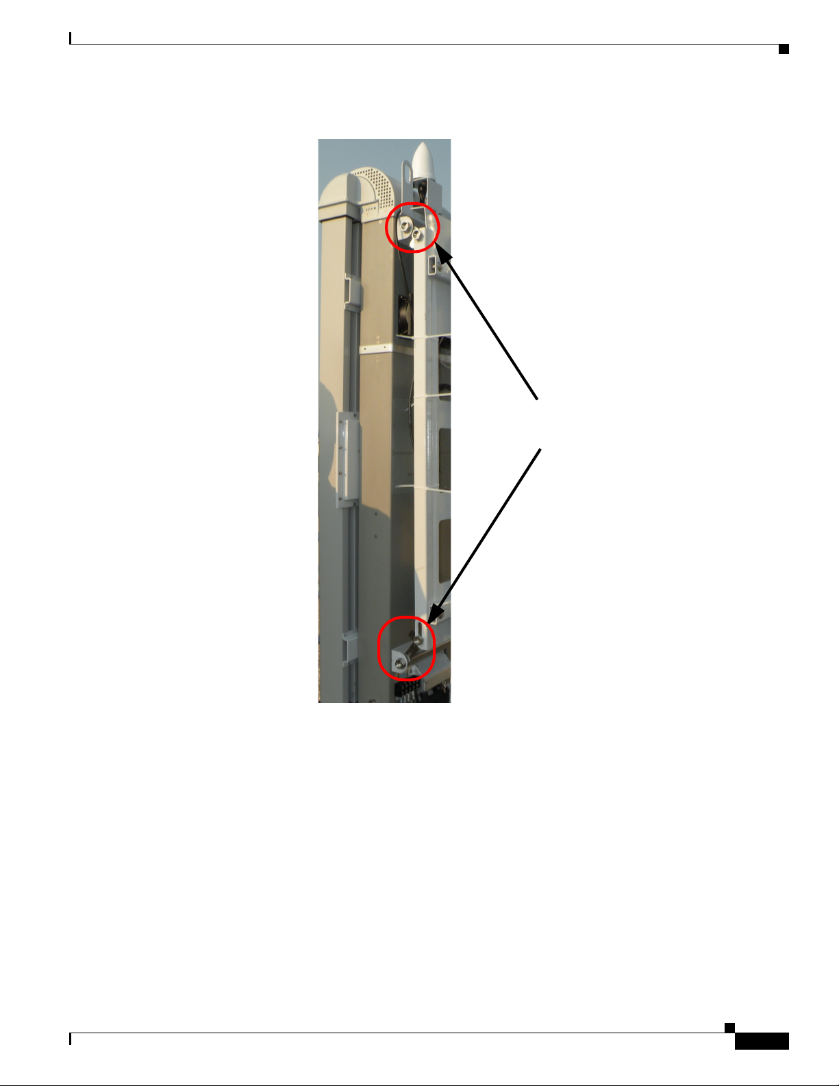
The downtilt can be adjusted per the assembly shown in Figure 6-19
°
°
°
°
°
°
°
°
°
°
°
°
1
1
1
1
1
1
1
1
1
1
1
1
+
+
+
+
+
+
+
+
+
+
+
+
Electr ical –6°
Electr ical –6°
Electr ical –6°
Electr ical –6°
Electr ical –6°
Electr ical –6°
Electr ical –6°
Electr ical –6°
Electr ical –6°
Electr ical –6°
Electr ical –6°
Electr ical –6°
–
–
–
–
–
–
–
–
–
–
–
–
°
°
°
°
°
°
°
°
°
°
°
°
5
5
5
5
5
5
5
5
5
5
5
5
° downtilt
° downtilt
6-18
BWX 8415 Basestation Installation and Commissioning Guide
OL-19519-01
Page 3
Chapter 6 Installation
6.3.8 Antenna Orientation
PRELIMINARY
Figure 6-19 Downtilt Adjustment Assembly
Downtilt Adjustment
Bracket Bolts
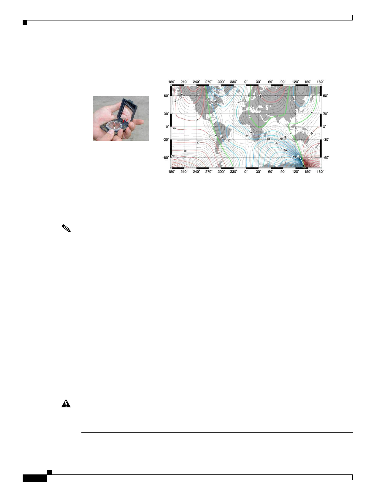
6.3.8 Antenna Orientation
The magnetic declination, which is the angular difference between observed magnetic north on a
compass and geographic (or “true”) north, shifts from year to year. Panel antennas must be oriented
appropriately as required by the RF plan.
Adjustments that will need to be made are based on the Magnetic Declination Chart (Figure 6-20), which
provides values to correct the compass reading and determine the true geographic East. Always check
for the latest chart information, which may be found at the following web address:
www.thecompassstore.com/decvar.html.
Since this is not the year 2000 any more, you will want to check this reference chart to learn how your
magnetic declination may have shifted since then. Notice that the map measures annual shifts in minutes.
Since it takes 60 minutes to equal 1 degree, if you notice that your location has a declination shift of 5
minutes per year, this means it will be another 12 years before your declination adjustment changes by
one whole degree.
OL-19519-01
BWX 8415 Basestation Installation and Commissioning Guide
6-19
Page 4
6.4 Power and Ground Cabling
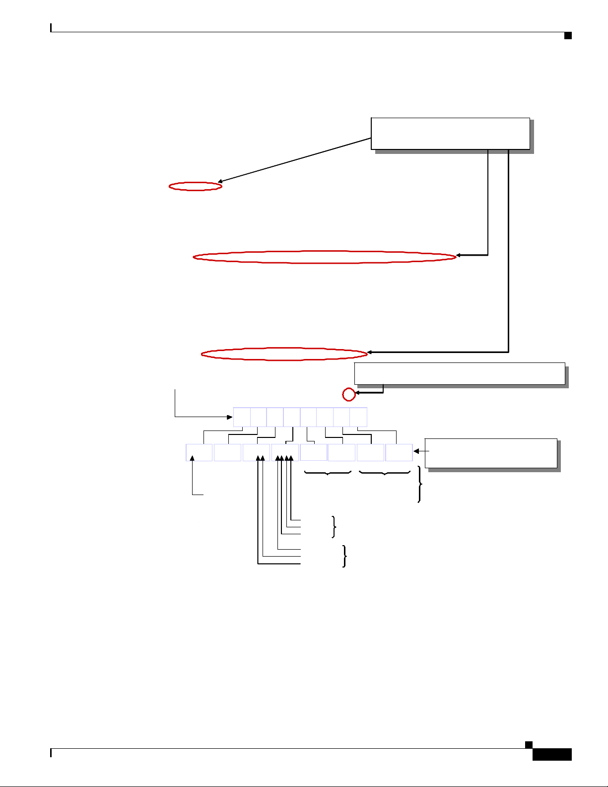
Figure 6-20 Magnetic Declination Chart – Example
PRELIMINARY
World Magnetic Declination Chart - Year 2000
World Magnetic Declination Chart - Year 2000
Use a compass to determine the magnetic East
Chapter 6 Installation
Unit:Degrees
Unit:Degrees
Use a Magnetic Declination chart to correct the compass reading
and determine the true geographic East
Note It is better to convert the “true” azimuth (which way the antenna should point in the horizontal plane) as
required by the RF Plan to the magnetic value that will be read on the compass before sending the
installer to the field. This way the installer will go by the reading on the compass, not having to worry
about magnetic declination corrections.
6.4 Power and Ground Cabling
6.4.1 Overview
The BS will operate at an input voltage of - 48 V DC, as measured at the input terminals to the BS.
General power and grounding information was covered in Chapter 5, “Pre-installation.” Please refer
there for information about power and ground cabling.
6.4.2 System Ground Cabling
6-20
The BS must be grounded prior to connecting power.
Warning
BWX 8415 Basestation Installation and Commissioning Guide
This equipment must be externally grounded using the supplied ground wire before power is applied.
Contact the appropriate electrical inspection authority or an electrician if you are uncertain that
suitable grounding is available.
Statement 366
OL-19519-01
Page 5
Chapter 6 Installation
6.4.2 System Ground Cabling
PRELIMINARY
Warning
Warning
Note It is strongly recommended that no switch or disconnect device be installed in the ground cabling.
Read the installation instructions before connecting the system to the power source.
When installing or replacing the unit, the ground connection must always be made first and
disconnected last.
Statement 1046
Statement 1004
In all installations and when powering the BS, you must follow these instructions to properly ground the
BS:
Step 1 Strip the insulation as required for the grounding lug.
Step 2 Use the appropriate crimping tool to crimp the supplied 6-AWG grounding lug to the bare copper ground
wire.
Step 3 Apply heat shrink to the grounding lug.
Step 4 Open the electrical joint compound (supplied), and apply a liberal amount over the metal surface where
the grounding connectors are located.
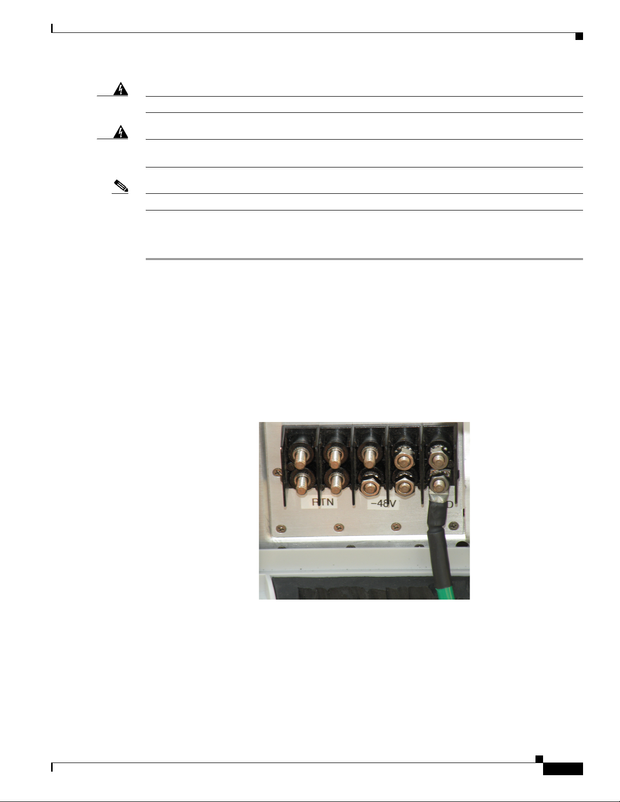
Step 5 Connect the ground cable to the BS ground using the supplied nuts with lock washers. Tighten the nuts
to 48 in-lbs. (5.4 Nm). Refer to
Figure 6-21.
Figure 6-21 Ground Cable Installed
Step 6 If necessary, strip the other end of the ground wire, and connect it to a reliable earth ground such as a
grounding rod or an appropriate grounding point on the pole/mast that is grounded.
OL-19519-01
BWX 8415 Basestation Installation and Commissioning Guide
6-21
Page 6

6.4.3 System Power Cabling
PRELIMINARY
6.4.2.1 Lightning Protection
Lightning protection information is covered in Chapter 5, “Pre-installation.” Please review that section
before continuing with the installation process.
6.4.2.1.1 Surge Arrestors
The BWX 8415 Basestation contains primary lightning protection on the GPS cable and the -48V power
cable. A DC primary lightning protector is also recommended at the output of the main power supply.
6.4.3 System Power Cabling
Install the power cable to the power connectors on the RU. Always refer to the regulatory standards for
power and grounding.
Chapter 6 Installation
Warning
Warning
Warning
Read the installation instructions before connecting the system to the power source.
A readily accessible two-poled disconnect device must be incorporated in the fixed wiring.
1022
Connect the unit only to DC power source that complies with the safety extra-low voltage (SELV)
requirements in IEC 60950 based safety standards.
Statement 1033
Statement 1004
Statement
Follow these instructions to properly connect the power cabling to the BS:
Step 1 If using insulated 6-AWG or 8-AWG copper wire, strip the insulation as required for the power lugs.
Step 2 Use the appropriate crimping tool to crimp the supplied 6-AWG or 8-AWG power lugs to the bare copper
wires.
Step 3 Apply heat shrink to the power lugs.
Step 4 Open the electrical joint compound (supplied), and apply a liberal amount over the metal surface where
the power connectors are located.
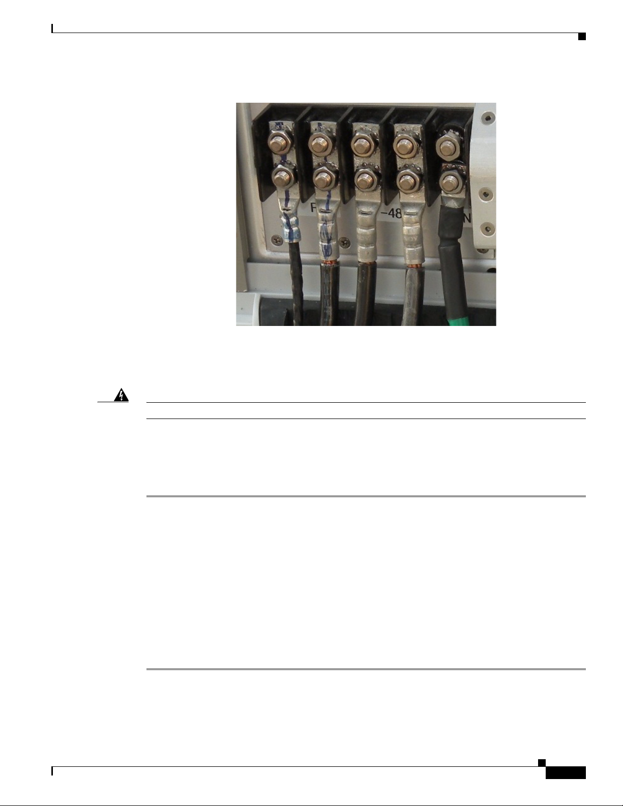
Step 5 Connect the power cable leads (2 RTN and 2 -48V) to the BS using the supplied nuts with lock washers.
Tighten the nuts to 48 in-lbs. (5.4 Nm). Refer to
Figure 6-22.
6-22
BWX 8415 Basestation Installation and Commissioning Guide
OL-19519-01
Page 7
Chapter 6 Installation
6.5 Fiber-Optic Cabling
PRELIMINARY
Figure 6-22 Power Cable Leads Installed
6.5 Fiber-Optic Cabling
Warning
Step 1 Ensure that the power source has been disconnected from the BS.
Step 2 Attach the Amphenol connector on the fiber-optic cable to the fiber-optic port on the BS and hand
Class 1 Laser product.
General fiber cable information was covered in Chapter 5, “Pre-installation.” Please refer to
5.8 Fiber-optic Cable Selection and 5.11 Confirm AAA, BWG, and Backhaul Network Availability for
information about the required fiber-optic cable and the backhaul connectivity.
To connect a fiber-optic cable to the access point, follow these steps:
tighten.
Statement 1008
6.6 Complete the BWX 8415 Installation
6.6.1 Install the I/O cable Cover
Perform the following steps to install the I/O cable cover.
OL-19519-01
Step 1 Install the I/O cable cover over the power, ground, fiber-optic, and GPS cable connections on the BWX
8415. Refer to
Figure 6-23.
BWX 8415 Basestation Installation and Commissioning Guide
6-23
Page 8

6.6.2 Test the Backhaul Connection
Chapter 6 Installation
PRELIMINARY
Figure 6-23 I/O Cable Cover
Step 2 Tighten the screws on the I/O cover securely to prevent water from leaking into the unit.
6.6.2 Test the Backhaul Connection
If required in the Responsibility Assignment Matrix (RAM) or project plan, test the backhaul to the
customer demarcation point.
6-24
BWX 8415 Basestation Installation and Commissioning Guide
OL-19519-01
Page 9

Chapter 7 Commissioning
PRELIMINARY
7.7 Calibration
7.7.1 What it Means to Calibrate
Performing a calibration on the BS detects the phase differential between the antenna elements and
matches the output power across all antenna elements in the BWX 8415 Antenna Unit. On a new
installation, the calibration procedure should be performed at least 3 times to verify consistency of the
returned values. Ensure that the BS has been powered on, with the Power Amplifiers on, for at least 15
minutes to allow them to warm up and stabilize.
Caution Do not attempt to calibrate the basestation while performing a software upgrade or downgrade.
Calibrating during an upgrade or downgrade can interfere with the loading of files into system
components and may produce faults or other problems.
7.7.2 Types of Calibration
7.7 Calibration
Assuming the BS has been powered up and left on for at least 15 minutes, and that all alarms have been
cleared, you can now run a calibration. There are 2 types of calibration:
• Full Calibration
• Online Calibration
Typically, only the Full Calibration is done manually by the service provider. For the initial installation,
the Full Calibration will be run at least 3 times.
Note Cisco recommends that a Full Calibration be performed on each BS, at least once every 4 weeks.
When a Full Calibration is invoked, the BS is out of service for about 2 minutes. After installation,
commissioning, and acceptance testing, Cisco recommends that a Full Calibration be run every 4 weeks
during off hours. During Full Calibration the Digital card pre-calibrates itself and the BS closes any
ongoing sessions with modems that are currently registered. The transmit gain in the IF section is
adjusted for each of the 8 transmit paths individually so that the level of power delivered at the base of
each antenna element is exactly the value specified by the Antenna Power parameter.
The receive gain is adjusted for each of the 8 receive paths individually so that when the level of power
specified by the Rx Sensitivity parameter is received at the base of each antenna element, it will
correspond to the maximum voltage that the card can handle. If the card is unable to adjust either the TX
gain or the RX gain for a particular antenna element, both gain values are set to zero (0) and this antenna
element is taken out of service.
Then, all paths are turned on using the gain settings just determined by the calibration, and the phase and
amplitude changes introduced in each sub-carrier between the BS and the base of each antenna path are
determined, both in the transmit and receive directions. This is done with power applied to all antenna
paths and using the TX and RX gains in the card, as determined in the previous step, in order to achieve
the power levels specified by the Antenna Power and Rx Sensitivity parameters.
OL-19519-01
Once the new phase change values are determined, they are compared with previous results kept in the
BS’s memory. If there is a large discrepancy with the previous results, an alarm is generated and the BS
uses the most likely correct set of values. Otherwise, the new results are sent to the EMS and kept in the
BS’s memory for future comparisons.
BWX 8415 Basestation Installation and Commissioning Guide
7-37
Page 10

7.7.3 Calibration Procedure
When the BS is calibrated, the measured values are stored in the BS and then reported to the EMS to be
stored under Air Interface > Layer 1. The Digital card pre-calibration values are placed in the General
tab. The TX and RX gain values are placed in the Antenna Table.
7.7.3 Calibration Procedure
Before you can calibrate, ensure the following requirements are met:
• The BS must have been previously added and configured in the EMS database
• The BS must be powered up for at least 15 minutes, booted properly, stable (not resetting) and all
alarms cleared before running the calibration
• Select the BS on the EMS CAM by clicking on the BS
Note The BS must be provisioned before you can calibrate. If the BS is not provisioned, refer to
7.6.3 Provision the BWX 8415 Basestation for the steps to perform the provisioning.
Step 1 Select Air Interface > Layer 1 > Layer 1 Tables.
Step 2 Click on Show Configuration.
Chapter 7 Commissioning
PRELIMINARY
Step 3 From a terminal emulation program type in the command, caldebugon and hit <Enter> (Figure 7-42).
Figure 7-42 Show Configuration
bts-221 [Active]% caldebugon
bts-221 [Active]% caldebugon
bts-221 [Active]% caldebugon
bts-221 [Active]% caldebugon
bts-221 [Active]% caldebugon
bts-221 [Active]% caldebugon
bts-221 [Active]% caldebugon
bts-221 [Active]% caldebugon
bts-221 [Active]% caldebugon
bts-221 [Active]% caldebugon
bts-221 [Active]% caldebugon
bts-221 [Active]% caldebugon
bts-221 [Active]% caldebugon
bts-221 [Active]% caldebugon
bts-221 [Active]% caldebugon
bts-221 [Active]% caldebugon
bts221 [Active]%
bts221 [Active]%
bts221 [Active]%
bts221 [Active]%
bts221 [Active]%
bts221 [Active]%
bts221 [Active]%
bts221 [Active]%
bts221 [Active]%
bts221 [Active]%
bts221 [Active]%
bts221 [Active]%
bts221 [Active]%
bts221 [Active]%
bts221 [Active]%
bts221 [Active]%
Mak e sure you t ype " c al de b ugof f
Mak e sure you t ype " c al de b ugof f
Mak e sure you t ype " c al de b ugof f
Mak e sure you t ype " c al de b ugof f
Mak e sure you t ype " c al de b ugof f
Mak e sure you t ype " c al de b ugof f
Mak e sure you t ype " c al de b ugof f
Mak e sure you t ype " c al de b ugof f
Mak e sure you t ype " c al de b ugof f
Mak e sure you t ype " c al de b ugof f
Mak e sure you t ype " c al de b ugof f
Mak e sure you t ype " c al de b ugof f
Mak e sure you t ype " c al de b ugof f
Mak e sure you t ype " c al de b ugof f
Mak e sure you t ype " c al de b ugof f
Mak e sure you t ype " c al de b ugof f
when you are done with the calibration!!!
when you are done with the calibration!!!
when you are done with the calibration!!!
when you are done with the calibration!!!
when you are done with the calibration!!!
when you are done with the calibration!!!
when you are done with the calibration!!!
when you are done with the calibration!!!
when you are done with the calibration!!!
when you are done with the calibration!!!
when you are done with the calibration!!!
when you are done with the calibration!!!
when you are done with the calibration!!!
when you are done with the calibration!!!
when you are done with the calibration!!!
when you are done with the calibration!!!
Step 4 With the Antenna Table tab selected, click on Calibrate
Terminal Emulation Program
Terminal Emulation Program
Terminal Emulation Program
Terminal Emulation Program
Terminal Emulation Program
Terminal Emulation Program
Terminal Emulation Program
Terminal Emulation Program
Terminal Emulation Program
Terminal Emulation Program
Terminal Emulation Program
Terminal Emulation Program
Terminal Emulation Program
Terminal Emulation Program
Terminal Emulation Program
Terminal Emulation Program
7-38
Step 5 Select Full Calibration and Calibrate and then click on Yes . Refer to Figure 7-43.
BWX 8415 Basestation Installation and Commissioning Guide
OL-19519-01
Page 11

Chapter 7 Commissioning
PRELIMINARY
Figure 7-43 Full Calibration
7.7.3 Calibration Procedure
Click on the “ Antenna
Click on the “ Antenna
Click on the “ Antenna
Click on the “ Antenna
Click on the “ Antenna
Click on the “ Antenna
Click on the “ Antenna
Click on the “ Antenna
Click on the “ Antenna
Ta ble”tab
Ta ble”tab
Ta ble”tab
Ta ble”tab
Ta ble”tab
Ta ble”tab
Ta ble”tab
Ta ble”tab
Ta ble”tab
Click on “Calibrate”
Click on “Calibrate”
Click on “Calibrate”
Click on “Calibrate”
Click on “Calibrate”
Click on “Calibrate”
Click on “Calibrate”
Click on “Calibrate”
Click on “Calibrate”
Se le ct “ Full
Se le ct “ Full
Se le ct “ Full
Se le ct “ Full
Se le ct “ Full
Se le ct “ Full
Se le ct “ Full
Se le ct “ Full
Se le ct “ Full
Calibration” and
Calibration” and
Calibration” and
Calibration” and
Calibration” and
Calibration” and
Calibration” and
Calibration” and
Calibration” and
click on “Calibrate”
click on “Calibrate”
click on “Calibrate”
click on “Calibrate”
click on “Calibrate”
click on “Calibrate”
click on “Calibrate”
click on “Calibrate”
click on “Calibrate”
Click on “Yes”
Click on “Yes”
Click on “Yes”
Click on “Yes”
Click on “Yes”
Click on “Yes”
Click on “Yes”
Click on “Yes”
Click on “Yes”
Note If you forgot to provision the BS in the EMS database, you will see the error shown in Figure 7-44. Click
on Ok and refer to 7.6.3 Provision the BWX 8415 Basestation.
Figure 7-44 Provision Error
When the calibration is complete, the Full Calibration window changes and displays the finish time and
the result. Note that the result of “Succeeded” means that the calibration finished, not that the
calibration results were successful (
Step 6 Click on Close to close the Full Calibration window
Figure 7-45).
OL-19519-01
BWX 8415 Basestation Installation and Commissioning Guide
7-39
Page 12

7.7.3 Calibration Procedure
Figure 7-45 Calibration Results
Step 7 Click on Show Configuration to see if the calibration is successful. In the EMS CAM highlight the BS
and check the Antenna Table transmit and receive gain values (
Chapter 7 Commissioning
PRELIMINARY
Figure 7-46).
Note A value of zero indicates that a proper value for the gain for that path (either in the TX or Rx direction)
could not be found.
Figure 7-46 Check Antenna Table Values
7-40
Step 8 Check the calibration results for the Transmit and Receive Gain Values.
Note The BS system has a Transmit Gain value range of 1-64 and a Receive Gain value range of either 115-255
or 0-140. When evaluating calibration gain words, it is important to remember that the size of the value
does not determine if a problem exists.
BWX 8415 Basestation Installation and Commissioning Guide
OL-19519-01
Page 13

Chapter 7 Commissioning
7.7.3 Calibration Procedure
PRELIMINARY
To determine if a problem exists, use the following information:
• At the BS console, look at the cal error message. The calibration should pass without any errors.
• Look at the Transmit Gain values. They should be relatively close to each other (values: 1 - 64).
• Find the median Transmit Gain value. The median is the value that falls in the middle of the
lowest to highest values. Example: If you ordered the values 9, 8, 8, 7, 7, 6, 5, 4, 3, 3, 3, 2, 1,
1….the median would be 5 because 5 falls midway from the top or bottom of the ranked values.
• Compare all the other Transmit Gain values to the median value. All Transmit Gain values
should be within a plus or minus range of 6 units from the median. Therefore, if the median is
50, values from 44 to 56 would be acceptable.
• Look at the Receive Gain values. (values: 115 – 255)
• Find the median Receive Gain value.
• Compare all the Receive Gain values to the median value. All Receive Gain values should be
within a plus or minus range of 8 units from the median.
Criteria:
Transmit Gain Words +/- 6 from the median value
Receive Gain Words +/- 8 from the median value
If this is a new installation (or a problem is found), repeat the calibration procedure (Steps 4-8). This
will be the second of three calibrations you will perform. Click on the Configure button for this BS, and
a new window appears (
Figure 7-47). The main “Show” window still shows the results of the first
calibration. The Configuration window shows the values corresponding to the second calibration.
Figure 7-47 Second Calibration (if needed)
OL-19519-01
BWX 8415 Basestation Installation and Commissioning Guide
7-41
Page 14

7.7.3 Calibration Procedure
Compare the values of both calibrations. The corresponding results should be within +/- 3 units. Close
the Configuration window, and click on Show Configuration to move the second calibration values into
the main window.
Next, perform a third calibration (Steps 4-8) and compare the results with the second calibration values.
An example of successful calibration results is provided in
results with errors is shown in Figure 7-49.
Figure 7-48 Example – Successful Calibration
Data received from Layer1:
Data received from Layer1:
antenna txGain rxGain
antenna txGain rxGain
0 18 67
0 18 67
1 15 67
1 15 67
2 17 63
2 17 63
3 18 71
3 18 71
4 15 68
4 15 68
5 17 70
5 17 70
6 17 63
6 17 63
7 16 67
7 16 67
carrierId antenna txCalWeightX txCalWeightY rxCalWeightX rxCalWeightY rxSNR txSNR
carrierId antenna txCalWeightX txCalWeightY rxCalWeightX rxCalWeightY rxSNR txSNR
0 0 32.0751 1167.99 8929.38 57776 14.8713 -58.0311
0 0 32.0751 1167.99 8929.38 57776 14.8713 -58.0311
0 1 -51.7158 1165.44 -17116.8 -56872.4 14.6449 -49.6681
0 1 -51.7158 1165.44 -17116.8 -56872.4 14.6449 -49.6681
0 2 712.152 858.821 25107.3 53970 14.9417 -65.6772
0 2 712.152 858.821 25107.3 53970 14.9417 -65.6772
0 3 970.448 649.556 2988.24 -57892.1 14.7349 -60.3216
0 3 970.448 649.556 2988.24 -57892.1 14.7349 -60.3216
0 4 -144.55 1162.05 -31553.2 -48341.8 14.5399 -52.7438
0 4 -144.55 1162.05 -31553.2 -48341.8 14.5399 -52.7438
0 5 -1152.3 188.353 9726.92 58129.3 14.7198 -56.5888
0 5 -1152.3 188.353 9726.92 58129.3 14.7198 -56.5888
0 6 671.034 -944.873 16581.7 55125.9 14.4144 -61.5753
0 6 671.034 -944.873 16581.7 55125.9 14.4144 -61.5753
0 7 -1037.14 -522.104 -14678.7 56342.4 14.4625 -59.1302
0 7 -1037.14 -522.104 -14678.7 56342.4 14.4625 -59.1302
1 0 1.413 1165.16 7420.12 58477.6 17.5769 -62.3292
1 0 1.413 1165.16 7420.12 58477.6 17.5769 -62.3292
1 1 -15.6843 1166.71 -14542.4 -56266.7 17.8756 -55.5523
1 1 -15.6843 1166.71 -14542.4 -56266.7 17.8756 -55.5523
Chapter 7 Commissioning
PRELIMINARY
Figure 7-48. An example of calibration
.………………………………………..
.………………………………………..
23 0 13.7061 1155.41 17919.3 56372.7
23 0 13.7061 1155.41 17919.3 56372.7
23 1 -110.214 1151.74 -23078.1 -53293.6
23 1 -110.214 1151.74 -23078.1 -53293.6
23 2 733.771 896.972 26636.7 52430.5
23 2 733.771 896.972 26636.7 52430.5
23 3 980.339 603.351 2003.94 -58427.1
23 3 980.339 603.351 2003.94 -58427.1
23 4 -81.1062 1142.55 -32936.2 -48987.9
23 4 -81.1062 1142.55 -32936.2 -48987.9
23 5 -1150.89 97.7796 8904.14 56862.3
23 5 -1150.89 97.7796 8904.14 56862.3
23 6 678.523 -942.895 14027.6 58078.8
23 6 678.523 -942.895 14027.6 58078.8
23 7 -1064.41 -435.91 -13482.4 55363.2
23 7 -1064.41 -435.91 -13482.4 55363.2
TX Syn Gain : 26
TX Syn Gain : 26
RX Syn Gain : 579
RX Syn Gain : 579
SC Syn Gain : 567
SC Syn Gain : 567
SC SYN Level : 8376
SC SYN Level : 8376
Cal Error : 0
Cal Error : 0
7-42
BWX 8415 Basestation Installation and Commissioning Guide
OL-19519-01
Page 15
Chapter 7 Commissioning
PRELIMINARY
Figure 7-49 Calibration With Errors
Data received from Layer1:
Data received from Layer1:
Data received from Layer1:
Data received from Layer1:
Data received from Layer1:
Data received from Layer1:
antenna txGain rxGain
antenna txGain rxGain
antenna txGain rxGain
antenna txGain rxGain
antenna txGain rxGain
antenna txGain rxGain
0 18 67
0 18 67
0 18 67
0 18 67
0 18 67
0 18 67
1 15 67
1 15 67
1 15 67
1 15 67
1 15 67
1 15 67
2 17 63
2 17 63
2 17 63
2 17 63
2 17 63
2 17 63
3 18 71
3 18 71
3 18 71
3 18 71
3 18 71
3 18 71
4 15 68
4 15 68
4 15 68
4 15 68
4 15 68
4 15 68
5 17 70
5 17 70
5 17 70
5 17 70
5 17 70
5 17 70
6 17 63
6 17 63
6 17 63
6 17 63
6 17 63
6 17 63
7 0 0
7 0 0
7 0 0
carrierId an tenna txCalWeightX txCalWeightY rxCalWeightX rxCalWei ghtY rxSNR txSNR
carrierId an tenna txCalWeightX txCalWeightY rxCalWeightX rxCalWei ghtY rxSNR txSNR
carrierId an tenna txCalWeightX txCalWeightY rxCalWeightX rxCalWei ghtY rxSNR txSNR
carrierId an tenna txCalWeightX txCalWeightY rxCalWeightX rxCalWei ghtY rxSNR txSNR
carrierId an tenna txCalWeightX txCalWeightY rxCalWeightX rxCalWei ghtY rxSNR txSNR
carrierId an tenna txCalWeightX txCalWeightY rxCalWeightX rxCalWei ghtY rxSNR txSNR
0 0 32.0751 1167.99 8929.38 57776 14.8713 -58.0311
0 0 32.0751 1167.99 8929.38 57776 14.8713 -58.0311
0 0 32.0751 1167.99 8929.38 57776 14.8713 -58.0311
0 0 32.0751 1167.99 8929.38 57776 14.8713 -58.0311
0 0 32.0751 1167.99 8929.38 57776 14.8713 -58.0311
0 0 32.0751 1167.99 8929.38 57776 14.8713 -58.0311
0 1 -51.7158 1165.44 -17116.8 -56872.4 14.6449 -49.6681
0 1 -51.7158 1165.44 -17116.8 -56872.4 14.6449 -49.6681
0 1 -51.7158 1165.44 -17116.8 -56872.4 14.6449 -49.6681
0 1 -51.7158 1165.44 -17116.8 -56872.4 14.6449 -49.6681
0 1 -51.7158 1165.44 -17116.8 -56872.4 14.6449 -49.6681
0 1 -51.7158 1165.44 -17116.8 -56872.4 14.6449 -49.6681
0 2 712.152 858.821 25107.3 53970 14.9417 -65.6772
0 2 712.152 858.821 25107.3 53970 14.9417 -65.6772
0 2 712.152 858.821 25107.3 53970 14.9417 -65.6772
0 2 712.152 858.821 25107.3 53970 14.9417 -65.6772
0 2 712.152 858.821 25107.3 53970 14.9417 -65.6772
0 2 712.152 858.821 25107.3 53970 14.9417 -65.6772
0 3 970.448 649.556 2988.24 -57892.1 14.7349 -60.3216
0 3 970.448 649.556 2988.24 -57892.1 14.7349 -60.3216
0 3 970.448 649.556 2988.24 -57892.1 14.7349 -60.3216
0 3 970.448 649.556 2988.24 -57892.1 14.7349 -60.3216
0 3 970.448 649.556 2988.24 -57892.1 14.7349 -60.3216
0 3 970.448 649.556 2988.24 -57892.1 14.7349 -60.3216
0 4 -144.55 1162.05 -31553.2 -48341.8 14.5399 -52.7438
0 4 -144.55 1162.05 -31553.2 -48341.8 14.5399 -52.7438
0 4 -144.55 1162.05 -31553.2 -48341.8 14.5399 -52.7438
0 4 -144.55 1162.05 -31553.2 -48341.8 14.5399 -52.7438
0 4 -144.55 1162.05 -31553.2 -48341.8 14.5399 -52.7438
0 4 -144.55 1162.05 -31553.2 -48341.8 14.5399 -52.7438
0 5 -1152.3 188.353 9 726.92 58129.3 14.7198 -56.5888
0 5 -1152.3 188.353 9 726.92 58129.3 14.7198 -56.5888
0 5 -1152.3 188.353 9 726.92 58129.3 14.7198 -56.5888
0 5 -1152.3 188.353 9 726.92 58129.3 14.7198 -56.5888
0 5 -1152.3 188.353 9 726.92 58129.3 14.7198 -56.5888
0 5 -1152.3 188.353 9 726.92 58129.3 14.7198 -56.5888
0 6 671.034 -944.873 16581.7 55125.9 14.4 144 -61.5753
0 6 671.034 -944.873 16581.7 55125.9 14.4 144 -61.5753
0 6 671.034 -944.873 16581.7 55125.9 14.4 144 -61.5753
0 6 671.034 -944.873 16581.7 55125.9 14.4 144 -61.5753
0 6 671.034 -944.873 16581.7 55125.9 14.4 144 -61.5753
0 6 671.034 -944.873 16581.7 55125.9 14.4 144 -61.5753
0 7 0 0 0 0 0 0
0 7
0 7
0 7
0 7 0 0 0 0 0 0
0 7 0 0 0 0 0 0
1 0 1.413 1165.16 7420.12 58477.6 17.5769 -62.3292
1 0 1.413 1165.16 7420.12 58477.6 17.5769 -62.3292
1 0 1.413 1165.16 7420.12 58477.6 17.5769 -62.3292
1 0 1.413 1165.16 7420.12 58477.6 17.5769 -62.3292
1 0 1.413 1165.16 7420.12 58477.6 17.5769 -62.3292
1 0 1.413 1165.16 7420.12 58477.6 17.5769 -62.3292
1 1 -15.6843 1166.71 -14542.4 -56266.7 17.8756 -55.5523
1 1 -15.6843 1166.71 -14542.4 -56266.7 17.8756 -55.5523
1 1 -15.6843 1166.71 -14542.4 -56266.7 17.8756 -55.5523
1 1 -15.6843 1166.71 -14542.4 -56266.7 17.8756 -55.5523
1 1 -15.6843 1166.71 -14542.4 -56266.7 17.8756 -55.5523
1 1 -15.6843 1166.71 -14542.4 -56266.7 17.8756 -55.5523
.………………………………………..
.………………………………………..
.………………………………………..
.………………………………………..
.………………………………………..
.………………………………………..
23 0 13.7061 1155.41 17919.3 56372.7
23 0 13.7061 1155.41 17919.3 56372.7
23 0 13.7061 1155.41 17919.3 56372.7
23 0 13.7061 1155.41 17919.3 56372.7
23 0 13.7061 1155.41 17919.3 56372.7
23 0 13.7061 1155.41 17919.3 56372.7
23 1 -110.214 1151.74 -23078.1 -53293.6
23 1 -110.214 1151.74 -23078.1 -53293.6
23 1 -110.214 1151.74 -23078.1 -53293.6
23 1 -110.214 1151.74 -23078.1 -53293.6
23 1 -110.214 1151.74 -23078.1 -53293.6
23 1 -110.214 1151.74 -23078.1 -53293.6
23 2 733.771 896.972 26636.7 52430.5
23 2 733.771 896.972 26636.7 52430.5
23 2 733.771 896.972 26636.7 52430.5
23 2 733.771 896.972 26636.7 52430.5
23 2 733.771 896.972 26636.7 52430.5
23 2 733.771 896.972 26636.7 52430.5
23 3 980.339 603.351 2003.94 -58427.1
23 3 980.339 603.351 2003.94 -58427.1
23 3 980.339 603.351 2003.94 -58427.1
23 3 980.339 603.351 2003.94 -58427.1
23 3 980.339 603.351 2003.94 -58427.1
23 3 980.339 603.351 2003.94 -58427.1
23 4 -81.1062 1142.55 -32936.2 -48987.9
23 4 -81.1062 1142.55 -32936.2 -48987.9
23 4 -81.1062 1142.55 -32936.2 -48987.9
23 4 -81.1062 1142.55 -32936.2 -48987.9
23 4 -81.1062 1142.55 -32936.2 -48987.9
23 4 -81.1062 1142.55 -32936.2 -48987.9
23 5 -1150.89 97.7796 8 904.14 56862.3
23 5 -1150.89 97.7796 8 904.14 56862.3
23 5 -1150.89 97.7796 8 904.14 56862.3
23 5 -1150.89 97.7796 8 904.14 56862.3
23 5 -1150.89 97.7796 8 904.14 56862.3
23 5 -1150.89 97.7796 8 904.14 56862.3
23 6 678.523 -942.895 14027.6 58078.8
23 6 678.523 -942.895 14027.6 58078.8
23 6 678.523 -942.895 14027.6 58078.8
23 6 678.523 -942.895 14027.6 58078.8
23 6 678.523 -942.895 14027.6 58078.8
23 6 678.523 -942.895 14027.6 58078.8
23 7 0 0 0 0
23 7
23 7
23 7
23 7 0 0 0 0
23 7 0 0 0 0
TX Syn Gain : 26
TX Syn Gain : 26
TX Syn Gain : 26
TX Syn Gain : 26
TX Syn Gain : 26
TX Syn Gain : 26
RX Syn Gain : 579
RX Syn Gain : 579
RX Syn Gain : 579
RX Syn Gain : 579
RX Syn Gain : 579
RX Syn Gain : 579
SC Syn Gain : 567
SC Syn Gain : 567
SC Syn Gain : 567
SC Syn Gain : 567
SC Syn Gain : 567
SC Syn Gain : 567
SC SYN Level : 8376
SC SYN Level : 8376
SC SYN Level : 8376
SC SYN Level : 8376
SC SYN Level : 8376
SC SYN Level : 8376
Cal Error : 80008000
Cal Error : 80008000
Cal Error : 80008000
Antenna Pow er = 15 Rx Sensitivity = 10 0 numAntenna = 7
Antenna Pow er = 15 Rx Sensitivity = 10 0 numAntenna = 7
Antenna Pow er = 15 Rx Sensitivity = 10 0 numAntenna = 7
Here is the key to
Here is the key to
Here is the key to
Here is the key to
Here is the key to
Here is the key to
Here is the key to interpret
Both gains and all the phase
Here is the key to interpret
Both gains and all the phase
Here is the key to interpret
Both gains and all the phase
Here is the key to
Here is the key to
Here is the key to
Here is the key to
Here is the key to
Here is the key to
Here is the key to
Here is the key to
Here is the key to
Here is the key to
Here is the key to
Here is the key to
the calibration error
the calibration error
the calibration error
the calibration error
the calibration error
the calibration error
the calibration error code
shifts for this path are set to zero.
the calibration error code
shifts for this path are set to zero.
the calibration error code
shifts for this path are set to zero.
interpret
interpret
interpret
interpret
interpret
interpret
the calibration error
the calibration error
the calibration error
the calibration error
the calibration error
the calibration error
Only 7 out of 8 antenna elements are
Only 7 out of 8 antenna elements are working
Only 7 out of 8 antenna elements are
Only 7 out of 8 antenna elements are working
Only 7 out of 8 antenna elements are working
Only 7 out of 8 antenna elements are
Only 7 out of 8 antenna elements are working
Only 7 out of 8 antenna elements are
Only 7 out of 8 antenna elements are working
Only 7 out of 8 antenna elements are working
Only 7 out of 8 antenna elements are
Only 7 out of 8 antenna elements are working
Only 7 out of 8 antenna elements are
Only 7 out of 8 antenna elements are working
Only 7 out of 8 antenna elements are working
Only 7 out of 8 antenna elements are
Only 7 out of 8 antenna elements are
Only 7 out of 8 antenna elements are
Only 7 out of 8 antenna elements are
Only 7 out of 8 antenna elements are
Only 7 out of 8 antenna elements are
Only 7 out of 8 antenna elements are
Only 7 out of 8 antenna elements are
Only 7 out of 8 antenna elements are
Only 7 out of 8 antenna elements are
Only 7 out of 8 antenna elements are
Only 7 out of 8 antenna elements are
Only 7 out of 8 antenna elements are
Only 7 out of 8 antenna elements are
Only 7 out of 8 antenna elements are
7.7.3 Calibration Procedure
8 0 0 0 8 0 0 0
8 0 0 0 8 0 0 0
8 0 0 0 8 0 0 08 0 0 0 8 0 0 0
8 0 0 0 8 0 0 0
8 0 0 0 8 0 0 0
8 0 0 0 8 0 0 08 0 0 0 8 0 0 0
8 0 0 0 8 0 0 0
8 0 0 0 8 0 0 0
8 0 0 0 8 0 0 0
8 0 0 0 8 0 0 08 0 0 0 8 0 0 0
8 0 0 0 8 0 0 0
8 0 0 0 8 0 0 0
8 0 0 0 8 0 0 08 0 0 0 8 0 0 0
8 0 0 0 8 0 0 0
8 0 0 0 8 0 0 0
8 0 0 0 8 0 0 0
1000 0000 0000 0000 1000 0000 0000 0000
1000 0000 0000 0000 1000 0000 0000 0000
1000 0000 0000 0000 1000 0000 0000 00001000 0000 0000 0000 1000 0000 0000 0000
1000 0000 0000 0000 1000 0000 0000 0000
1000 0000 0000 0000 1000 0000 0000 0000
1000 0000 0000 0000 1000 0000 0000 00001000 0000 0000 0000 1000 0000 0000 0000
1000 0000 0000 0000 1000 0000 0000 0000
1000 0000 0000 0000 1000 0000 0000 0000
1000 0000 0000 0000 1000 0000 0000 00001000 0000 0000 0000 1000 0000 0000 0000
1000 0000 0000 0000 1000 0000 0000 0000
1000 0000 0000 0000 1000 0000 0000 0000
1000 0000 0000 0000 1000 0000 0000 00001000 0000 0000 0000 1000 0000 0000 0000
7654 32107654 3210
7654 32107654 3210
7654 32107654 3210
7654 32107654 3210
7654 32107654 3210
7654 32107654 3210
7654 32107654 3210
7654 32107654 3210
7654 32107654 3210
7654 32107654 3210
7654 32107654 3210
7654 32107654 3210
7654 32107654 3210
7654 32107654 3210
SNR
SNR
SNR
SNR
SNR
SNR
SNR
SNR
SNR
SNR
SNR
SNR
SNR
SNR
Problem
Problem
Problem:
Problem
Problem
Problem:
Problem:
Problem
Problem
Problem:
Problem
Problem
Problem:
Problem:
1stbit = Rx
1stbit = Rx
1stbit = Rx
1stbit = Rx
nd
nd
nd
nd
2
2
2
2
bit = Tx
bit = Tx
bit = Tx
bit = Tx
Rx error
Rx error
Rx error
Rx error
Rx error
Rx error
Rx error
Rx error
Rx e rror
Rx e rror
Rx e rror
Rx e rror
Rx e rror
Rx e rror
in antenna
in antenna
in antenna
in antenna
in antenna
in antenna
in antenna
in antenna
in antenna
in antenna
in antenna
in antenna
in antenna
in antenna
element #
element #
element #
element #
element #
element #
element #
element #
element #
element #
element #
element #
element #
element #
Rx Gain
Rx Gain
Rx Gain
Rx Gain
Rx Gain
Rx Gain
Rx Gain
Rx Gain
Rx Gain
Rx Gain
Rx Gain
Rx Gain
Rx Gain
Rx Gain
SC Gain
SC Gain
SC Gain
SC Gain
SC Gain
SC Gain
SC Gain
SC Gain
SC Gain
SC Gain
SC Gain
SC Gain
SC Gain
SC Gain
Tx Gain
TGain
Gai n
Tx Gain
TGain
Gai n
Gai n
Tx Gain
TGain
Gai n
Tx Gain
TGain
Gai n
Gai n
Rx Range
Rx Range
Rx Range
Rx Range
Rx Range
Rx Range
Rx Range
Rx Range
Rx Range
Rx Range
Rx Range
Rx Range
Rx Range
Rx Range
TX Range
TX Range
TX Range
TX Range
TX Range
TX Range
TX Range
TX Range
TX Range
TX Range
TX Range
TX Range
TX Range
TX Range
Temp Range
Temp Range
Temp Range
Temp Range
Temp Range
Temp Range
Temp Range
Temp Range
Temp Range
Temp Range
Temp Range
Temp Range
Temp Range
Temp Range
Tx error
error
Tx error
error
Tx error
error
Tx error
error
in antenna
in antenna
in antenna
in antenna
in antenna
in antenna
in antenna
in antenna
in antenna
in antenna
in antenna
in antenna
in antenna
in antenna
element #
element #
element #
element #
Pre-Cal errors - A power or gain setting could not be
Pre-Cal errors - A power or gain setting could not be
Pre-Cal errors - A power or gain setting could not be
Pre-Cal errors - A power or gain setting could not be
Pre-Cal errors - A power or gain setting could not be
Pre-Cal errors - A power or gain setting could not be
Pre-Cal errors - A power or gain setting could not be
Pre-Cal errors - A power or gain setting could not be
Pre-Cal errors - A power or gain setting could not be
Pre-Cal errors - A power or gain setting could not be
Pre-Cal errors - A power or gain setting could not be
Pre-Cal errors - A power or gain setting could not be
Pre-Cal errors - A power or gain setting could not be
Pre-Cal errors - A power or gain setting could not be
found th at would set the signal at the appropriate level
found th at would set the signal at the appropriate level
found that would set the signal at the appropriate level
found th at would set the signal at the appropriate level
found th at would set the signal at the appropriate level
found that would set the signal at the appropriate level
found that would set the signal at the appropriate level
found th at would set the signal at the appropriate level
found th at would set the signal at the appropriate level
found that would set the signal at the appropriate level
found th at would set the signal at the appropriate level
found th at would set the signal at the appropriate level
found that would set the signal at the appropriate level
found that would set the signal at the appropriate level
Pre-Cal errors - The target value is outside
Pre -Cal erro rs -
Pre -Cal erro rs -
Pre-Cal errors - The target value is outside
Pre -Cal erro rs -
Pre -Cal erro rs -
Pre -Cal erro rs -
Pre-Cal errors - The target value is outside
Pre -Cal erro rs -
Pre -Cal erro rs -
Pre-Cal errors - The target value is outside
Pre -Cal erro rs -
Pre -Cal erro rs -
Pre -Cal erro rs the range of the Synthesizer card
the range of the Synthesizer card
the range of the Synthesizer card
the range of the Synthesizer card
the range of the Synthesizer card
the range of the Synthesizer card
the range of the Synthesizer card
the range of the Synthesizer card
the range of the Synthesizer card
the range of the Synthesizer card
the range of the Synthesizer card
the range of the Synthesizer card
the range of the Synthesizer card
the range of the Synthesizer card
Here is the key to
Here is the key to
Here is the key to
Here is the key to
Here is the key to
Here is the key to
Here is the key to interpret
Here is the key to interpret
Here is the key to interpret
Here is the key to interpret
Here is the key to interpret
Here is the key to interpret
Here is the key to
Here is the key to
Here is the key to
Here is the key to
Here is the key to
Here is the key to
Here is the key to
Here is the key to
Here is the key to
Here is the key to
Here is the key to
Here is the key to
the calibration error
the calibration error
the calibration error
the calibration error
the calibration error
the calibration error
the calibration error code
the calibration error code
the calibration error code
the calibration error code
the calibration error code
the calibration error code
interpret
interpret
interpret
interpret
interpret
interpret
the calibration error
the calibration error
the calibration error
the calibration error
the calibration error
the calibration error
Errors durin g offlin e power
Errors durin g offlin e power
Errors durin g offlin e power
Errors durin g offlin e power
and gain tuning calibration
and gain tuning calibration
and gain tuning calibration
and gain tuning calibration
OL-19519-01
BWX 8415 Basestation Installation and Commissioning Guide
7-43
 Loading...