

Page 1

Cisco 12006 and Cisco 12406 Router Installation and Configuration Guide
Corporate Headquarters
Cisco Systems, Inc.
170 West Tasman Drive
San Jose, CA 95134-1706
USA
http://www.cisco.com
Tel: 408 526-4000
800 553-NETS (6387)
Fax: 408 526-4100
Text Part Number: OL-11497-03
Page 2

THE SPECIFICATIONS AND INFORMATION REGARDING THE PRODUCTS IN THIS MANUAL ARE SUBJECT TO CHANGE WITHOUT
NOTICE. ALL STATEMENTS, INFORMATION, AND RECOMMENDATIONS IN THIS MANUAL ARE BELIEVED TO BE ACCURATE BUT
ARE PRESENTED WITHOUT WARRANTY OF ANY KIND, EXPRESS OR IMPLIED. USERS MUST TAKE FULL RESPONSIBILITY FOR
THEIR APPLICATION OF ANY PRODUCTS.
THE SOFTWARE LICENSE AND LIMITED WARRANTY FOR THE ACCOMPANYING PRODUCT ARE SET FORTH IN THE INFORMATION
PACKET THAT SHIPPED WITH THE PRODUCT AND ARE INCORPORATED HEREIN BY THIS REFERENCE. IF YOU ARE UNABLE TO
LOCATE THE SOFTWARE LICENSE OR LIMITED WARRANTY, CONTACT YOUR CISCO REPRESENTATIVE FOR A COPY.
The following information is for FCC compliance of Class A devices: This equipment has been tested and found to comply with the limits for a Class
A digital device, pursuant to part 15 of the FCC rules. These limits are designed to provide reasonable protection against harmful interference when
the equipment is operated in a commercial environment. This equipment generates, uses, and can radiate radio-frequency energy and, if not installed
and used in accordance with the instruction manual, may cause harmful interference to radio communications. Operation of this equipment in a
residential area is likely to cause harmful interference, in which case users will be required to correct the interference at their own expense.
The following information is for FCC compliance of Class B devices: The equipment described in this manual generates and may radiate
radio-frequency energy. If it is not installed in accordance with Cisco’s installation instructions, it may cause interference with radio and television
reception. This equipment has been tested and found to comply with the limits for a Class B digital device in accordance with the specifications in
part 15 of the FCC rules. These specifications are designed to provide reasonable protection against such interference in a residential installation.
However, there is no guarantee that interference will not occur in a particular installation.
Modifying the equipment without Cisco’s written authorization may result in the equipment no longer complying with FCC requirements for Class
A or Class B digital devices. In that event, your right to use the equipment may be limited by FCC regulations, and you may be required to correct
any interference to radio or television communications at your own expense.
You can determine whether your equipment is causing interference by turning it off. If the interference stops, it was probably caused by the Cisco
equipment or one of its peripheral devices. If the equipment causes interference to radio or television reception, try to correct the interference by
using one or more of the following measures:
• Turn the television or radio antenna until the interference stops.
• Move the equipment to one side or the other of the television or radio.
• Move the equipment farther away from the television or radio.
• Plug the equipment into an outlet that is on a different circuit from the television or radio. (That is, make certain the equipment and the television
or radio are on circuits controlled by different circuit breakers or fuses.)
Modifications to this product not authorized by Cisco Systems, Inc. could void the FCC approval and negate your authority to operate the product.
The Cisco implementation of TCP header compression is an adaptation of a program developed by the University of California, Berkeley (UCB) as
part of UCB’s public domain version of the UNIX operating system. All rights reserved. Copyright © 1981, Regents of the University of California.
NOTWITHSTANDING ANY OTHER WARRANTY HEREIN, ALL DOCUMENT FILES AND SOFTWARE OF THESE SUPPLIERS ARE
PROVIDED “AS IS” WITH ALL FAULTS. CISCO AND THE ABOVE-NAMED SUPPLIERS DISCLAIM ALL WARRANTIES, EXPRESSED
OR
IMPLIED, INCLUDING, WITHOUT LIMITATION, THOSE OF MERCHANTABILITY, FITNESS FOR A PARTICULAR PURPOSE AND
NONINFRINGEMENT OR ARISING FROM A COURSE OF DEALING, USAGE, OR TRADE PRACTICE.
IN NO EVENT SHALL CISCO OR ITS SUPPLIERS BE LIABLE FOR ANY INDIRECT, SPECIAL, CONSEQUENTIAL, OR INCIDENTAL
DAMAGES, INCLUDING, WITHOUT LIMITATION, LOST PROFITS OR LOSS OR DAMAGE TO DATA ARISING OUT OF THE USE OR
INABILITY TO USE THIS MANUAL, EVEN IF CISCO OR ITS SUPPLIERS HAVE BEEN ADVISED OF THE POSSIBILITY OF SUCH
DAMAGES.
Page 3

CCVP, the Cisco logo, and Welcome to the Human Network are trademarks of Cisco Systems, Inc.; Changing the Way We Work, Live, Play, and Learn is
a service mark of Cisco Systems, Inc.; and Access Registrar, Aironet, Catalyst, CCDA, CCDP, CCIE, CCIP, CCNA, CCNP, CCSP, Cisco, the Cisco
Certified Internetwork Expert logo, Cisco IOS, Cisco Press, Cisco Systems, Cisco Systems Capital, the Cisco Systems logo, Cisco Unity,
Enterprise/Solver, EtherChannel, EtherFast, EtherSwitch, Fast Step, Follow Me Browsing, FormShare, GigaDrive, HomeLink, Internet Quotient, IOS,
iPhone, IP/TV, iQ Expertise, the iQ logo, iQ Net Readiness Scorecard, iQuick Study, LightStream, Linksys, MeetingPlace, MGX, Networkers,
Networking Academy, Network Registrar, PIX, ProConnect, ScriptShare, SMARTnet, StackWise, The Fastest Way to Increase Your Internet Quotient,
and TransPath are registered trademarks of Cisco Systems, Inc. and/or its affiliates in the United States and certain other countries.
All other trademarks mentioned in this document or Website are the property of their respective owners. The use of the word partner does not imply a
partnership relationship between Cisco and any other company. (0711R)
Cisco 12006 and Cisco 12406 Router Installation and Configuration Guide
Copyright © 2001-2006, Cisco Systems, Inc. All rights reserved.
Page 4

Page 5

Preface xiii
Audience xiii
Purpose xiii
Organization xiv
Document Conventions xv
Obtaining Documentation xvi
Cisco.com xvi
Product Documentation DVD xvii
Ordering Documentation xvii
Documentation Feedback xviii
Cisco Product Security Overview xviii
Reporting Security Problems in Cisco Products xix
CONTENTS
CHAPTER
OL-11497-03
Obtaining Technical Assistance xx
Cisco Technical Support and Documentation Website xx
Submitting a Service Request xxi
Definitions of Service Request Severity xxi
Obtaining Additional Publications and Information xxii
1 Product Overview 1-1
Introduction 1-1
Product Description 1-2
Physical and Functional Description 1-7
Chassis 1-7
RP and Line Card Slots 1-7
Cisco 12006 and Cisco 12406 Router Installation and Configuration Guide
v
Page 6

Contents
Switch Fabric Card Slots 1-8
Alarm Card Slots 1-8
Chassis Backplane 1-8
Power 1-9
Cooling 1-9
Multigigabit Crossbar Switch Fabric 1-10
Switch Fabric Card Types 1-10
Nonredundant and Redundant System Configurations 1-11
Switch Fabric Switching Capacity and Router Type 1-12
Switch Fabric Redundancy 1-12
Maintenance Bus 1-13
Power-Up/Down Control 1-13
Device Discovery 1-13
Code Download 1-14
Diagnostics 1-14
Environmental Monitoring and Alarms 1-14
vi
Route Processors 1-15
Route Processor Functions 1-15
Route Processor Types 1-16
Performance Route Processor 1-25
Line Cards 1-33
Alarm Cards 1-35
Power Subsystems 1-37
AC Power Subsystem 1-38
DC Power Subsystem 1-42
Blower Module 1-47
Air Filters 1-49
Cable-Management System 1-50
Field-Replaceable Units 1-52
Cisco 12006 and Cisco 12406 Router Installation and Configuration Guide
OL-11497-03
Page 7

Technical Specifications 1-52
Contents
CHAPTER
2 Preparing for Installation 2-1
Tools and Equipment 2-2
Safety and Compliance 2-2
General Safety Guidelines 2-3
Compliance and Safety Information 2-5
Laser Safety 2-5
Lifting Guidelines 2-5
Preventing Electrostatic Discharge Damage 2-6
Attaching an ESD-Preventive Strap 2-7
Safety with Electricity 2-8
Site Requirement Guidelines 2-9
Environmental Guidelines 2-9
Rack-Mounting Guidelines 2-10
Power Connection Guidelines 2-14
Site Wiring 2-20
Unpacking and Repacking the Router 2-21
Site Preparation Checklist 2-22
CHAPTER
OL-11497-03
3 Installing the Router 3-1
Installing a Router 3-2
Installing the Rack-Mount Brackets (Optional) 3-3
Installing Center-Mount Brackets (Optional) 3-5
Installing the Chassis in a Rack 3-7
Installing the Chassis on a Tabletop or Flat Surface 3-9
Supplemental Bonding and Grounding Connections 3-9
Connecting RP and Line Card Cables 3-11
Connecting Alarm Card Cables 3-13
Cisco 12006 and Cisco 12406 Router Installation and Configuration Guide
vii
Page 8

Contents
Connecting to the Console and Auxiliary Ports 3-14
GRP Console and Auxiliary Ports 3-14
PRP Console and Auxiliary Ports 3-18
Installing a Flash Memory Card 3-20
Connecting the GRP to an Ethernet Network 3-22
Connecting the PRP to an Ethernet Network 3-25
Connecting to an AC Power Source 3-29
Connecting to a DC Power Source 3-32
Power On the Router 3-35
IOS Software Configuration for the Router 3-37
Cisco IOS Software Images 3-37
Conditions to Check Before System Startup 3-38
Overview of the Boot Process 3-39
Starting the Router and Observing Initial Conditions 3-39
Manually Booting the System 3-47
Router Configuration 3-49
viii
Cisco IOS User Interface 3-50
User Interface Command Modes 3-50
Configuration Changes 3-53
setup Command Interactive Script Example 3-54
Configuring Global Parameters 3-57
Configuring Network Interfaces 3-58
Checking the Software Version 3-61
Verifying the Running Configuration Settings 3-62
Saving the Running Configuration Settings to NVRAM 3-64
Reviewing the Running Configuration Settings 3-64
Using Flash Memory Cards in the RP 3-66
Installing the Flash Memory Card in a RP 3-66
Removing the Flash Memory Card from an RP 3-67
Cisco 12006 and Cisco 12406 Router Installation and Configuration Guide
OL-11497-03
Page 9

Formatting a Flash Memory Card 3-67
Specify a Boot Image 3-68
Flash Memory Console Commands 3-69
Booting from Flash Memory 3-72
Copying Files 3-72
Copying a Cisco IOS Software Image 3-74
Copying Cisco IOS Software Updates 3-75
Copying Files Between RP Memory and a Flash Memory Card 3-77
Locked Blocks in Flash Memory Cards 3-82
If You Need More Information 3-82
Cisco IOS Software Configuration Information and Support 3-82
Contents
CHAPTER
CHAPTER
4 Troubleshooting the Installation 4-1
Performing Other Configuration Tasks 4-1
Configuring the Software Configuration Register 4-1
Recovering a Lost Password 4-11
Problem Solving with Subsystems 4-14
Identifying Startup Problems 4-15
Using LEDs to Gather Information 4-16
Troubleshooting the Power Subsystem 4-23
Troubleshooting the Processor Subsystem 4-28
Troubleshooting by Using the Alarm Cards 4-33
Troubleshooting the Cooling Subsystem 4-35
5 Field Diagnostics for the Cisco 12000 Series Router 5-1
Diagnostics Overview 5-2
FPGA Overview 5-3
Using Diagnostics 5-6
Obtain and Place the Diagnostics Image 5-6
OL-11497-03
Cisco 12006 and Cisco 12406 Router Installation and Configuration Guide
ix
Page 10

Contents
Upgrade the FPGA Image on a Line Card 5-7
Using the diag Command 5-8
Cisco 12000 Series Router Line Cards 5-8
Cisco 12000 Series Router RPs 5-9
Cisco 12000 Series Router SFCs and CSCs 5-9
diag Command Reference 5-9
Output Examples 5-14
CHAPTER
6 Maintaining the Router 6-1
Powering Down the Router 6-2
Removing and Installing the Front Door on Cisco 12006 and Cisco 12406 Enhanced
Series Router
6-3
Cleaning or Replacing the Air Filters 6-7
Removing and Replacing the Blower Module 6-9
Troubleshooting the Blower Installation 6-12
Removing and Replacing AC and DC Power Subsystem Components 6-13
Installation Guidelines 6-14
Power Supply and PDU Compatibility 6-14
Installing Upgrade Kits 6-17
Removing and Replacing an AC PEM 6-18
Troubleshooting the AC Power Supply Installation 6-22
Removing and Replacing an AC PDU 6-24
Removing and Replacing a DC PEM 6-31
Troubleshooting the DC Power Supply Installation 6-35
Removing and Replacing a DC PDU 6-37
Removing and Installing an RP or a Line Card 6-47
Tools and Equipment 6-48
Removing an RP or Line Card 6-48
Installing an RP or Line Card 6-50
Cisco 12006 and Cisco 12406 Router Installation and Configuration Guide
x
OL-11497-03
Page 11

Contents
Adding an RP or Line Card 6-51
Installing a Line Card Cable-Management Bracket 6-52
Reconnecting Cables to a Line Card 6-54
Removing and Installing a Clock and Scheduler Card, Switch Fabric Card, or Alarm
6-56
Card
Tools and Equipment 6-57
Removing and Installing a Clock and Scheduler Card 6-57
Removing and Installing a Switch Fabric Card 6-61
Removing and Installing an Alarm Card 6-65
Removing and Installing the Chassis 6-68
Tools and Equipment 6-68
Before You Begin 6-69
Preparing the Replacement Chassis 6-69
Preparing the Defective Chassis 6-70
Transferring System Components 6-71
Detaching the Supplemental Bonding and Grounding Connection 6-74
Removing the Chassis 6-74
Installing the Replacement Chassis 6-75
Reattaching the Supplemental Bonding and Grounding Cable 6-76
Reconnecting Cables to the Replacement Chassis 6-76
Reconnecting Power to the Router 6-77
Installing the Blower Module 6-77
Restarting the Router 6-77
APPENDIX
OL-11497-03
Upgrading the RP and Line Card Memory 6-77
A Technical Specifications A-1
Specifications A-1
Alarm Card Alarm Relay Connector Specifications A-6
Router Performance Upgrades and Model Identification A-6
Cisco 12006 and Cisco 12406 Router Installation and Configuration Guide
xi
Page 12

I
NDEX
Contents
xii
Cisco 12006 and Cisco 12406 Router Installation and Configuration Guide
OL-11497-03
Page 13

Audience
Preface
The Cisco 12006 and Cisco 12406 Router Installation and Configuration Guide
is written for hardware installers and system administrators of Cisco routers.
This publication assumes that the user has a substantial background in installing
and configuring router and switch-based hardware. The reader should also be
familiar with electronic circuitry and wiring practices, and have experience as an
electronic or electromechanical technician.
Purpose
OL-11497-03
This installation and configuration guide contains procedures for installing the
router hardware, creating a basic startup configuration file, and powering on the
router for the first time.
Cisco 12006 and Cisco 12406 Router Installation and Configuration Guide
xiii
Page 14

Organization
The Cisco 12006 and Cisco 12406 Router Installation and Configuration Guide
contains the following chapters, appendix, and index.
• Chapter 1, “Product Overview”—Presents a high-level system overview and
• Chapter 2, “Preparing for Installation”—Discusses safety, site requirements
• Chapter 3, “Installing the Router”—Gives the procedures for the initial
• Chapter 4, “Troubleshooting the Installation”—Explains how to identify and
• Chapter 5, “Field Diagnostics for the Cisco 12000 Series
physical description of the major components of Cisco 12006 and
Cisco
12406 Routers, including the power and cooling systems, Gigabit
Route Processor (GRP), Performance Route Processor (PRP), clock and
scheduler cards (CSC), switch fabric cards (SFC), and alarm cards, and gives
a functional overview.
for power, environmental safety, cabling, rack-mounting, electrostatic
discharge (ESD), unpacking, site log, and site preparation checklist.
installation and setup of Cisco 12006 and Cisco 12406 Routers.
solve problems that might occur during installation.
Router”—Describes how to load and run the field diagnostics for the
Cisco 12000 Series Internet Router.
xiv
• Chapter 6, “Maintaining the Router”—Explains safety at the
field-replaceable unit (FRU) level, removal and replacement procedures for
field-replaceable units and assemblies, and associated procedures to
troubleshoot and verify FRU and device operation.
• Appendix A, “Technical Specifications”—Provides the technical
specifications and connector cable specifications for Cisco 12006 and
Cisco
12406 Routers.
• Index
Cisco 12006 and Cisco 12406 Router Installation and Configuration Guide
OL-11497-03
Page 15

Document Conventions
This publication uses the following conventions:
• Ctrl- represents the key labeled Control. For example, the key combination
Ctrl-z means hold down the Control key while you press the z
Command descriptions use these conventions:
• Examples that contain system prompts denote interactive sessions, indicating
the commands that you should enter at the prompt. The system prompt
indicates the current level of the EXEC command interpreter.
For example, the prompt router> indicates that you should be at the user
level, and the prompt
level. Access to the privileged level usually requires a password. Refer to the
related software configuration and reference documentation for additional
information.
• Commands and keywords are in boldface font.
• Arguments for which you supply values are in italic font.
• Elements in square brackets ([ ]) are optional.
• Alternative but required keywords are grouped in braces ({ }) and separated
by vertical bars (|).
key.
router# indicates that you should be at the privileged
OL-11497-03
Examples use these conventions:
• Terminal sessions and sample console screen displays are in screen font.
• Information you enter is in boldface screen font.
• Nonprinting characters, such as passwords, are in angle brackets (< >).
• Default responses to system prompts are in square brackets ([ ]).
• Exclamation points (!) at the beginning of a line indicate a comment line.
Caution Means reader be careful. You are capable of doing something that might result in
equipment damage or loss of data.
Note Means reader take note. Notes contain helpful suggestions or references to
materials not contained in this manual.
Cisco 12006 and Cisco 12406 Router Installation and Configuration Guide
xv
Page 16

Timesaver Means the described action saves time. You can save time by performing the
action described in the paragraph.
Warning
This warning symbol means danger. You are in a situation that could cause
bodily injury. Before you work on any equipment, be aware of the hazards
involved with electrical circuitry and be familiar with standard practices for
preventing accidents. To see translations of the warnings that appear in this
publication, refer to the Regulatory Compliance and Safety Information
document that accompanied this device.
Obtaining Documentation
Cisco documentation and additional literature are available on Cisco.com. Cisco
also provides several ways to obtain technical assistance and other technical
resources. These sections explain how to obtain technical information from Cisco
Systems.
Cisco.com
You can access the most current Cisco documentation at this URL:
http://www.cisco.com/techsupport
You can access the Cisco website at this URL:
http://www.cisco.com
You can access international Cisco websites at this URL:
http://www.cisco.com/public/countries_languages.shtml
xvi
Cisco 12006 and Cisco 12406 Router Installation and Configuration Guide
OL-11497-03
Page 17

Product Documentation DVD
Cisco documentation and additional literature are available in the Product
Documentation DVD package, which may have shipped with your product. The
Product Documentation DVD is updated regularly and may be more current than
printed documentation.
The Product Documentation DVD is a comprehensive library of technical product
documentation on portable media. The DVD enables you to access multiple
versions of hardware and software installation, configuration, and command
guides for Cisco products and to view technical documentation in HTML. With
the DVD, you have access to the same documentation that is found on the Cisco
website without being connected to the Internet. Certain products also have .pdf
versions of the documentation available.
The Product Documentation DVD is available as a single unit or as a subscription.
Registered Cisco.com users (Cisco direct customers) can order a Product
Documentation DVD (product number DOC-DOCDVD=) from the Ordering tool
or Cisco Marketplace.
Cisco Ordering tool:
http://www.cisco.com/en/US/partner/ordering/
Cisco Marketplace:
http://www.cisco.com/go/marketplace/
Ordering Documentation
Beginning June 30, 2005, registered Cisco.com users may order Cisco
documentation at the Product Documentation Store in the Cisco Marketplace at
this
URL:
http://www.cisco.com/go/marketplace/
Cisco will continue to support documentation orders using the Ordering tool:
• Registered Cisco.com users (Cisco direct customers) can order
documentation from the Ordering
http://www.cisco.com/en/US/partner/ordering/
Cisco 12006 and Cisco 12406 Router Installation and Configuration Guide
OL-11497-03
tool:
xvii
Page 18

• Instructions for ordering documentation using the Ordering tool are at
this URL:
http://www.cisco.com/univercd/cc/td/doc/es_inpck/pdi.htm
• Nonregistered Cisco.com users can order documentation through a local
account representative by calling Cisco Systems Corporate Headquarters
(California, USA) at 408
calling 1 800
553-NETS (6387).
Documentation Feedback
You can rate and provide feedback about Cisco technical documents by
completing the online feedback form that appears with the technical documents
on Cisco.com.
You can send comments about Cisco documentation to bug-doc@cisco.com.
You can submit comments by using the response card (if present) behind the front
cover of your document or by writing to the following address:
Cisco Systems
Attn: Customer Document Ordering
170 West Tasman Drive
San Jose, CA 95134-9883
We appreciate your comments.
526-7208 or, elsewhere in North America, by
Cisco Product Security Overview
Cisco provides a free online Security Vulnerability Policy portal at this URL:
http://www.cisco.com/en/US/products/products_security_vulnerability_policy.ht
ml
From this site, you can perform these tasks:
• Report security vulnerabilities in Cisco products.
• Obtain assistance with security incidents that involve Cisco products.
• Register to receive security information from Cisco.
Cisco 12006 and Cisco 12406 Router Installation and Configuration Guide
xviii
OL-11497-03
Page 19

A current list of security advisories and notices for Cisco products is available at
this
URL:
http://www.cisco.com/go/psirt
If you prefer to see advisories and notices as they are updated in real time, you
can access a Product Security Incident Response Team Really Simple Syndication
(PSIRT RSS) feed from this
http://www.cisco.com/en/US/products/products_psirt_rss_feed.html
URL:
Reporting Security Problems in Cisco Products
Cisco is committed to delivering secure products. We test our products internally
before we release them, and we strive to correct all vulnerabilities quickly. If you
think that you might have identified a vulnerability in a Cisco product, contact
PSIRT:
• Emergencies — security-alert@cisco.com
An emergency is either a condition in which a system is under active attack
or a condition for which a severe and urgent security vulnerability should be
reported. All other conditions are considered nonemergencies.
• Nonemergencies — psirt@cisco.com
In an emergency, you can also reach PSIRT by telephone:
OL-11497-03
• 1 877 228-7302
• 1 408 525-6532
Tip We encourage you to use Pretty Good Privacy (PGP) or a compatible product to
encrypt any sensitive information that you send to Cisco. PSIRT can work from
encrypted information that is compatible with PGP versions
Never use a revoked or an expired encryption key. The correct public key to use
in your correspondence with PSIRT is the one linked in the Contact Summary
section of the Security Vulnerability Policy page at this
http://www.cisco.com/en/US/products/products_security_vulnerability_policy.ht
ml
Cisco 12006 and Cisco 12406 Router Installation and Configuration Guide
2.x through 8.x.
URL:
xix
Page 20

The link on this page has the current PGP key ID in use.
Obtaining Technical Assistance
Cisco Technical Support provides 24-hour-a-day award-winning technical
assistance. The Cisco Technical Support & Documentation website on Cisco.com
features extensive online support resources. In addition, if you have a valid Cisco
service contract, Cisco Technical Assistance Center (TAC) engineers provide
telephone support. If you do not have a valid Cisco service contract, contact your
reseller.
Cisco Technical Support and Documentation Website
The Cisco Technical Support andDocumentation website provides online
documents and tools for troubleshooting and resolving technical issues with Cisco
products and technologies. The website is available 24 hours a day, at this
http://www.cisco.com/techsupport
Access to all tools on the Cisco Technical Support & Documentation website
requires a Cisco.com user ID and password. If you have a valid service contract
but do not have a user ID or password, you can register at this
http://tools.cisco.com/RPF/register/register.do
URL:
URL:
xx
Note Use the Cisco Product Identification (CPI) tool to locate your product serial
number before submitting a web or phone request for service. You can access the
CPI tool from the Cisco Technical Support & Documentation website by clicking
the Tools & Resources link under Documentation & Tools. Choose Cisco
Product Identification Tool from the Alphabetical Index drop-down list, or click
the Cisco Product Identification Tool link under Alerts & RMAs. The CPI tool
offers three search options: by product ID or model name; by tree view; or for
certain products, by copying and pasting show command output. Search results
show an illustration of your product with the serial number label location
highlighted. Locate the serial number label on your product and record the
information before placing a service call.
Cisco 12006 and Cisco 12406 Router Installation and Configuration Guide
OL-11497-03
Page 21

Submitting a Service Request
Using the online TAC Service Request Tool is the fastest way to open S3 and S4
service requests. (S3 and S4 service requests are those in which your network is
minimally impaired or for which you require product information.) After you
describe your situation, the TAC Service Request Tool provides recommended
solutions. If your issue is not resolved using the recommended resources, your
service request is assigned to a Cisco engineer. The TAC Service Request Tool is
located at this URL:
http://www.cisco.com/techsupport/servicerequest
For S1 or S2 service requests or if you do not have Internet access, contact the
Cisco TAC by telephone. (S1 or S2 service requests are those in which your
production network is down or severely degraded.) Cisco engineers are assigned
immediately to S1 and S2 service requests to help keep your business operations
running smoothly.
To open a service request by telephone, use one of the following numbers:
Asia-Pacific: +61 2 8446 7411 (Australia: 1 800 805 227)
EMEA: +32 2 704 55 55
USA: 1 800 553-2447
For a complete list of Cisco TAC contacts, go to this URL:
http://www.cisco.com/techsupport/contacts
Definitions of Service Request Severity
To ensure that all service requests are reported in a standard format, Cisco has
established severity definitions.
Severity 1 (S1)—Your network is “down,” or there is a critical impact to your
business operations. You and Cisco will commit all necessary resources around
the clock to resolve the situation.
Severity 2 (S2)—Operation of an existing network is severely degraded, or
significant aspects of your business operation are negatively affected by
inadequate performance of Cisco products. You and Cisco will commit full-time
resources during normal business hours to resolve the situation.
Cisco 12006 and Cisco 12406 Router Installation and Configuration Guide
OL-11497-03
xxi
Page 22

Severity 3 (S3)—Operational performance of your network is impaired, but most
business operations remain functional. You and Cisco will commit resources
during normal business hours to restore service to satisfactory levels.
Severity 4 (S4)—You require information or assistance with Cisco product
capabilities, installation, or configuration. There is little or no effect on your
business operations.
Obtaining Additional Publications and Information
Information about Cisco products, technologies, and network solutions is
available from various online and printed sources.
• Cisco Marketplace provides a variety of Cisco books, reference guides,
documentation, and logo merchandise. Visit Cisco Marketplace, the company
store, at this
http://www.cisco.com/go/marketplace/
• Cisco Press publishes a wide range of general networking, training and
certification titles. Both new and experienced users will benefit from these
publications. For current Cisco Press titles and other information, go to Cisco
Press at this
http://www.ciscopress.com
• Pack et magazine is the Cisco Systems technical user magazine for
maximizing Internet and networking investments. Each quarter, Packet
delivers coverage of the latest industry trends, technology breakthroughs, and
Cisco products and solutions, as well as network deployment and
troubleshooting tips, configuration examples, customer case studies,
certification and training information, and links to scores of in-depth online
resources. You can access Packet magazine at this
http://www.cisco.com/packet
• iQ Magazine is the quarterly publication from Cisco Systems designed to
help growing companies learn how they can use technology to increase
revenue, streamline their business, and expand services. The publication
identifies the challenges facing these companies and the technologies to help
URL:
URL:
URL:
xxii
Cisco 12006 and Cisco 12406 Router Installation and Configuration Guide
OL-11497-03
Page 23

solve them, using real-world case studies and business strategies to help
readers make sound technology investment decisions. You can access iQ
Magazine at this URL:
http://www.cisco.com/go/iqmagazine
or view the digital edition at this URL:
http://ciscoiq.texterity.com/ciscoiq/sample/
• Internet Protocol Journal is a quarterly journal published by Cisco Systems
for engineering professionals involved in designing, developing, and
operating public and private internets and intranets. You can access the
Internet Protocol Journal at this
http://www.cisco.com/ipj
• Networking products offered by Cisco Systems, as well as customer support
services, can be obtained at this
http://www.cisco.com/en/US/products/index.html
• Networking Professionals Connection is an interactive website for
networking professionals to share questions, suggestions, and information
about networking products and technologies with Cisco experts and other
networking professionals. Join a discussion at this
http://www.cisco.com/discuss/networking
• World-class networking training is available from Cisco. You can view
current offerings at this
URL:
URL:
URL:
URL:
OL-11497-03
http://www.cisco.com/en/US/learning/index.html
Cisco 12006 and Cisco 12406 Router Installation and Configuration Guide
xxiii
Page 24

xxiv
Cisco 12006 and Cisco 12406 Router Installation and Configuration Guide
OL-11497-03
Page 25

Introduction
CHA P T E R
1
Product Overview
This chapter provides an overview of the Cisco 12006 and Cisco 12406 series
routers. It contains physical descriptions of the router hardware and major
components, and functional descriptions of the hardware-related features.
The routers described in this guide are part of the Cisco 12006 and Cisco 12406
series routers and include:
• The original Cisco 12006 and Cisco 12406 series routers.
• The Cisco 12006 and Cisco 12406 enhanced series routers. The enhanced
series of routers use higher capacity power supplies, a more powerful blower
module, and have a new front door.
OL-11497-03
Note Most illustrations are shown without the new front door for clarity.
Cisco 12006 and Cisco 12406 Router Installation and Configuration Guide
1-1
Page 26

Product Description
These two router models are differentiated by the switching capacity of the switch
fabric installed in the router:
• Cisco 12006 Router—2.5-Gbps switch fabric
• Cisco 12406 Router—10-Gbps switch fabric
Other than their various capacities, these routers are almost identical. Differences
between each router are described unless otherwise noted, all information in this
publication applies to all routers.
Product Description
The Cisco 12006 and Cisco 12406 routers, shown in Figure 1-1, are members of
the Cisco 12000 series router family. These routers are aimed at scaling the
Internet and enterprise backbones to speeds of 155 Mbps (OC-3/STM-1),
622
Mbps (OC-12/STM-4), 2.4 Gbps (OC-48/STM-16), and 10 Gbps
(OC-192/STM).
Chapter 1 Product Overview
1-2
Cisco 12006 and Cisco 12406 Router Installation and Configuration Guide
OL-11497-03
Page 27
Chapter 1 Product Overview
Product Description
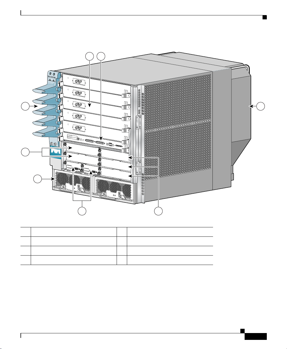
Figure 1-1 Cisco 12006 and Cisco 12406 router (Front View)
1 2
8 3
T
C
E
1
J
-
E
T
O
T
L
E
S
S
0
E
T
R
O
L
S
X
U
A
7
C
ISC
O
12000
S
E
R
IE
S
G
IG
A
B
IT
S
W
IT
C
H
R
O
U
T
E
R
L
L
O
X
C
R
5
4
-
CONSOLE
J
R
K
X
N
I
T
L
I
I
M
GIGABIT ROUTE PROCESSOR
6
5
4
1 Line card slots (five) 5 Alarm card slots (two)
2 RP slot 6 Power module bays (two)
3 Blower module 7 CSC slots (two)
4 SFC slots (three) 8 Cable-management bracket
With a chassis height of 18.5 inches (46.9 cm), four Cisco 12006 and
Cisco
12406 routers can be installed in a single standard 7-foot (2.15-m)
equipment rack.
Cisco 12006 and Cisco 12406 routers support system software downloads for
most Cisco IOS software upgrades, which enables you to remotely download,
store, and boot from a new Cisco IOS image.
Cisco 12006 and Cisco 12406 Router Installation and Configuration Guide
OL-11497-03
101344
1-3
Page 28

Product Description
Chapter 1 Product Overview
Cisco 12006 and Cisco 12406 routers have the following key features:
• Route Processor (RP)—Slot 5 (bottom slot) is the recommended slot for the
first RP. When the router is equipped with a redundant RP, it can be installed
in any of the five regular line card slots.
• Line Cards—Up to five OC-192 line cards, four if redundant RPs are
installed. These slots support the online insertion and removal (OIR) feature
so installed cards are hot-swappable: A failed card can be removed and
replaced with the router powered on.
• Clock and Scheduler Cards (CSCs) and Switch Fabric Cards (SFCs)—Two
dedicated hot-swappable slots for CSCs; three dedicated hot-swappable slots
for SFCs.
Note The Cisco 12006 Router uses 2.5-Gbps switch fabric; the
Cisco
12406 Router uses 10-Gbps switch fabric. You cannot mix
2.5-Gbps switch fabric cards and 10-Gbps switch fabric cards in a
chassis. The router will not operate with a mix of switch fabric card
types.
1-4
Note When operating your router with a single CSC, the second CSC slot
must have a CSC blank filler (MAS-GSR6-CSCBLNK=) installed to
ensure EMI compliance.
• Two dedicated alarm card slots (for 1+1 redundancy)
• Alarm and Illumination—Alarm and illumination for operating ranges in the
card cage, clock and scheduler card, and switch fabric card bays.
• Two hot-swappable AC-input power supplies or DC-input power entry
modules (PEMs).
Note When operating your router on a single AC-input power supply or
DC-input PEM, the second power module bay must have a blank filler
(MAS-GSR-PWRBLANK=) installed to ensure EMI compliance.
Cisco 12006 and Cisco 12406 Router Installation and Configuration Guide
OL-11497-03
Page 29

Chapter 1 Product Overview
• All power modules and other field replaceable units (FRUs), except for the
• All source power connections are located at the rear of the chassis on the
• Enhanced models have a new stylish front door that hides router cabling. The
• Network Equipment Building Systems—Cisco 12006 and Cisco 12406
• Electromagnetic Compatibility and Electrostatic Discharge Compliant—
• Bonding and Grounding—Bonding and grounding for safety, circuit
• Environmental Monitoring—Cisco 12006 and Cisco 12406 router complies
• Shock and Vibration—Cisco 12006 and Cisco 12406 routers have been
Product Description
air blower module and the power distribution unit (PDU), can be removed
from the front of the chassis.
PDU. (See
door can be installed to open from the right side or left side to give you total
flexibility.
routers comply with the Network Equipment Building System (NEBS)
Criteria Level 3 requirements defined in SR-3580 for flammability,
structural, and electronics compliance.
Cisco
electrostatic discharge (ESD) standards for both product and packaging.
protection, noise currents, reliability, and operations compliance.
with environmental monitoring standards for operating temperature and
humidity, as well as handling temperature and humidity (except for heat
dissipation).
shock- and vibration-tested for operating ranges, handling, and earthquake
standards to NEBS (Zone 4 per GR-63-Core). These tests have been
conducted in earthquake environment and criteria, office vibration and
criteria, transportation vibration and criteria, and packaged equipment shock
criteria.
Figure 1-2.)
12006 and Cisco 12406 routers comply with emissions, immunity, and
OL-11497-03
Cisco 12006 and Cisco 12406 Router Installation and Configuration Guide
1-5
Page 30
Product Description
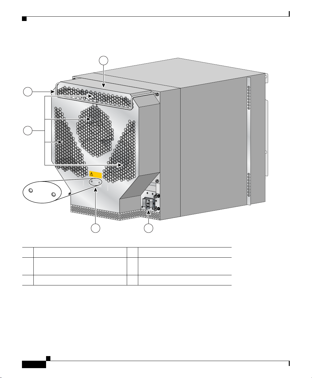
Figure 1-2 Cisco 12006 and Cisco 12406 router (Rear View)
1
3
4
HIGH SPEED BLOWER
Chapter 1 Product Overview
2 5
1 Blower module 4 Air exhaust vents
2 Blower module LEDs 5 PDU (behind Blower module; AC
PDU shown)
3 Blower module handle – –
• Fiber Cable Management—Fiber cable management with support for
high-density fiber Fast Ethernet (FE) ports.
• Current 1.275-inch pitch line cards will fit in the line card cage with the
addition of a front panel adapter cover. The line card adapter cover is included
with the 1.275-inch line card.
Cisco 12006 and Cisco 12406 Router Installation and Configuration Guide
1-6
101114
OL-11497-03
Page 31

Chapter 1 Product Overview
Physical and Functional Description
The main physical components of Cisco 12006 and Cisco 12406 routers and their
functions are described in the following sections:
• Chassis, page 1-7
• Multigigabit Crossbar Switch Fabric, page 1-10
• Maintenance Bus, page 1-13
• Route Processors, page 1-15
• Line Cards, page 1-33
• Alarm Cards, page 1-35
• Power Subsystems, page 1-37
• Blower Module, page 1-47
• Air Filters, page 1-49
• Cable-Management System, page 1-50
Physical and Functional Description
Chassis
The Cisco 12006 and Cisco 12406 router chassis is an enclosure that consists of
two integral card cages and two power module bays. (see
RP and Line Card Slots
The RP and line card cage has six user-configurable slots that support one RP and
up to five line cards. Network interfaces reside on the line cards that connect the
switch fabric of the router to the external networks. For more information about
the role of the RP, see the
information about the role of the line cards, see the “Line Cards” section on
page 1-33.
Note Cisco 12006 and Cisco 12406 routers use line cards that are compatible with
other Cisco 12000 series routers.
Cisco 12006 and Cisco 12406 Router Installation and Configuration Guide
OL-11497-03
Figure 1-1.)
“Route Processors” section on page 1-15. For more
1-7
Page 32

Chassis
Switch Fabric Card Slots
The switch fabric circuitry resides in five fabric card slots: two for CSCs and three
for SFCs. (See
fabric circuitry, see the “Multigigabit Crossbar Switch Fabric” section on
page 1-10.
Figure 1-1.) For more information about the role of the switch
Alarm Card Slots
Cisco 12006 and Cisco 12406 routers are equipped with two alarm cards. These
cards are positioned beside one another and occupy two card slots directly under
the CSC slots. (See
cards, see the “Alarm Cards” section on page 1-35.
Note The two alarm cards occupy slots under the two CSC slots in the CSC card cage,
but are not part of the switch fabric.
Chapter 1 Product Overview
Figure 1-1.) For more information about the role of the alarm
Chassis Backplane
All of the card cages are tied together electrically through a passive system
backplane in the back of the chassis. Nearly all of the wiring and circuitry in the
chassis is contained within or connected to the chassis backplane. The chassis
backplane distributes DC power to all of the cards in the chassis as well as the
blower module, and provides the physical communication pathway between
cards, both for network data and system communication across the internal system
maintenance bus (MBus).
Cisco 12006 and Cisco 12406 Router Installation and Configuration Guide
1-8
OL-11497-03
Page 33

Chapter 1 Product Overview
Power
Caution To ensure that the chassis configuration complies with the required power
Cooling
Chassis
Because a Cisco 12006 or Cisco 12406 Router can be configured with either an
AC-input power system or a DC-input power system, the power module bays will
accept either AC-input power supply modules or DC-input PEMs. For more
information about the power subsystems, see the
page 1-37.
budgets, use the on-line power calculator. Failure to properly verify the
configuration may result in an unpredictable state if one of the power units fails.
Contact your local sales representative for assistance.
Cisco 12006 and Cisco 12406 routers are equipped with a blower module to
distribute air within the chassis. The blower module is a removable module
located on the rear of the chassis. (See
the blower module, see the “Blower Module” section on page 1-47.
Figure 1-2.) For more information about
“Power Subsystems” section on
OL-11497-03
Cisco 12006 and Cisco 12406 Router Installation and Configuration Guide
1-9
Page 34

Multigigabit Crossbar Switch Fabric
Multigigabit Crossbar Switch Fabric
Cisco 12006 and Cisco 12406 router switch fabric circuity provides synchronized
gigabit-speed interconnections for the line cards and the RP. The switch fabric
circuitry resides in five fabric card slots: two for CSCs; three for SFCs. (See
Figure 1-3.)
Figure 1-3 Clock and Scheduler and Switch Fabric Card Bays
EJECT
SLOT-1
RESET
SLOT-0
CISCO 12000
G
IG
A
B
IT
S
W
IT
C
S
ER
H
R
O
U
T
IES
E
R
AUX
CSC
CSC
Alarm
cards (2)
COLL
RX
CONSOLE
RJ-45
TX
LINK
MII
G
IGA
B
IT
R
O
U
T
E
PR
O
C
ES
SO
R
SFC
SFC
SFC
Chapter 1 Product Overview
57084
Switch Fabric Card Types
The CSCs are installed in the half-width slots labeled CSC 0 and CSC 1 on the
lower left side of the chassis, located directly beneath the RP and line card cage
and directly above the alarm card bays. The three SFCs are installed in the
half-width slots labeled SFC
chassis.
Note To operate, Cisco 12006 and Cisco 12406 routers must have at least one CSC card
installed, in addition to SFC and alarm cards.
The CSC contains the following functionality:
Cisco 12006 and Cisco 12406 Router Installation and Configuration Guide
1-10
0, SFC 1, and SFC 2 on the lower right side of the
OL-11497-03
Page 35

Chapter 1 Product Overview
Multigigabit Crossbar Switch Fabric
• System clock—The system clock synchronizes data transfers between line
cards or between the RP and a line card, through the switch fabric. In systems
with redundant CSCs, the two system clocks are synchronized so that if one
system clock fails, the other clock takes over. The system clock signal is sent
to all line cards, the RP, and switch fabric cards.
• Scheduler—The scheduler handles requests from the line cards for access to
the switch fabric. When the scheduler receives a request from a line card for
switch fabric access, the scheduler determines when to allow the line card
access to the switch fabric.
• Switch fabric—The switch fabric carries the user traffic between line cards or
between the RP and the line cards. The switch fabric card contains only the
switch fabric circuitry and receives scheduling information and system clock
information from the CSC.
The SFC contains only the switch fabric circuitry, which carries user traffic
between line cards or between the RP and the line cards. The SFC receives
scheduling information and the system clock sent from the CSC.
Nonredundant and Redundant System Configurations
OL-11497-03
Cisco 12006 and Cisco 12406 routers are available in two system configurations:
1. Nonredundant configuration that includes one CSC and one power supply.
When you order a Cisco 12006 or Cisco 12406 Router, the nonredundant
configuration is shipped by default.
2. Redundant configuration that includes two CSCs and two power supplies.
For the redundant configuration, EMI compliance and cooling requirements are
met by having two CSCs and two power supplies installed in the system.
For the nonredundant configuration, EMI compliance and cooling requirements
are met only when blank fillers are installed in place of either (or both) the second
(unused) CSC slot or the second (unused) power supply bay.
Note When operating your router with a single CSC, the second CSC slot must have a
CSC blank filler (MAS-GSR6-CSCBLNK=) installed to ensure EMI compliance.
Cisco 12006 and Cisco 12406 Router Installation and Configuration Guide
1-11
Page 36

Chapter 1 Product Overview
Multigigabit Crossbar Switch Fabric
Switch Fabric Switching Capacity and Router Type
The Cisco 12006 Router is based on a 2.5-Gbps switch fabric, where each CSC or
SFC provides a 2.5-Gbps full-duplex connection to each line card in the system.
The 2.5-Gbps switch fabric consists of the 12006
Card (product number 12006-CSC=) and the 12006
(product number 12006-SFC=). The 2.5-Gbps switch fabric for the
Cisco
12006 Router can be identified by the Cisco identification labels on the
switch fabric cards (SFCs and CSCs): The CSC is labeled CSC-30/120 and the
SFC is labeled SFC-30/120.
The Cisco 12406 Router is based on a 10-Gbps switch fabric, where each CSC or
SFC provides a 10-Gbps full-duplex connection to each line card in the system.
The 10-Gbps switch fabric consists of the Clock and Scheduler Card (product
number GSR6-CSC=) and the Switch Fabric Card (product number GSR6-SFC=).
The 10-Gbps switch fabric cards are labeled simply CSC and SFC.
Note You cannot mix 2.5-Gbps switch fabric cards and 10-Gbps switch fabric cards in
a chassis. The router will not operate with a mix of switch fabric card types.
Advanced Clock and Scheduler
Advanced Switch Fabric Card
Switch Fabric Redundancy
Equipping the router with two CSCs provides data path, scheduler, and reference
clock redundancy. The interfaces between the line cards and the switch fabric are
monitored constantly. If the router detects a loss of synchronization (LOS), it
automatically activates the data paths of the redundant CSC, and data flows across
the redundant path. The switch to the redundant CSC occurs within 0.5 second,
with little or no loss of data.
Cisco 12006 and Cisco 12406 Router Installation and Configuration Guide
1-12
OL-11497-03
Page 37

Chapter 1 Product Overview
Maintenance Bus
The Cisco 12006 and Cisco 12406 router maintenance bus and MBus modules
manage the maintenance functions of the system. The MBus is integrated into the
backplane and consists of two separate buses, providing MBus redundancy.
Both MBus networks are linked to all the following items:
• Route processor and line cards
• CSCs, SFCs, and alarm cards
• Power modules
• Blower module
The MBus module located on each component communicates over the MBus and
is powered by DC voltage directly from the alarm card. The MBus performs the
functions of power-up/down control for each component, component (device)
discovery, code download, diagnostics, and environmental monitoring and
alarms.
Maintenance Bus
Power-Up/Down Control
Each MBus module directly controls the DC-DC converters on the component on
which it is mounted, based on commands the component receives from its
on-board EPROM and from the RP. Each MBus module is tied directly to DC
voltage from the alarm card.
When power is applied to the router, all MBus modules immediately power up.
The MBus modules on the RP and CSC immediately turn on the DC-DC
converter, powering up the respective card. The line card MBus module waits to
power up the line card until it receives a command from the RP.
Device Discovery
The RP uses the MBus to detect the system configuration. The RP sends a
message over the MBus requesting identity information from all installed devices.
The responses provide component type, as well as slot numbers for the line cards,
CSCs, SFCs, and alarm cards.
Cisco 12006 and Cisco 12406 Router Installation and Configuration Guide
OL-11497-03
1-13
Page 38

Maintenance Bus
Code Download
A portion of the line card operating software can be downloaded from the RP to
the line card over the MBus. Because the MBus is relatively slow compared to the
switch fabric, only enough code is downloaded to the line card for it to access the
switch fabric and complete the download process.
Diagnostics
The diagnostic software image is downloaded from the RP to the line card during
the test sequence.
Environmental Monitoring and Alarms
The MBus module on each component monitors the environment of that
component as follows:
• Line cards and the RP are monitored for temperature by two temperature
sensors mounted on each card. The MBus module makes voltage adjustments
through software for the +2.5
converters.
• Clock and scheduler cards and switch fabric cards are monitored for
temperature by two temperature sensors mounted on each card. The MBus
module makes voltage adjustments through software for the +2.5
+3.3
VDC converters.
VDC, +3.3 VDC, and +5 VDC DC-DC
Chapter 1 Product Overview
VDC and
1-14
• The MBus module on the alarm card makes voltage adjustments for +5 VDC.
• Environmental monitoring includes voltage monitoring, temperature
monitoring, and sensing for the blower module fans.
Cisco 12006 and Cisco 12406 Router Installation and Configuration Guide
OL-11497-03
Page 39

Chapter 1 Product Overview
Route Processors
Each Cisco 12006 and Cisco 12406 router has one main system (or route)
processor. The route processor (RP) processes the network routing protocols and
distributes updates to the Cisco Express Forwarding (CEF) tables on the line
cards. The RP also performs general maintenance functions, such as diagnostics,
console support, and line card monitoring.
Route Processor Functions
The RP performs the following are primary functions:
• Downloading the Cisco IOS software to all of the installed line cards at
power-up
• Providing a console (terminal) port for router configuration
• Providing an auxiliary port for other external equipment, such as modems
• Providing an IEEE 802.3, 10/100-megabit-per-second (Mbps) Ethernet port
for Telnet functionality
• Running routing protocols
Route Processors
OL-11497-03
• Building and distributing routing tables to the line cards
• Providing general system maintenance functions for the router
The RP will function in any slot in the line card/RP card cage, but slot 5 is the
recommended slot. If the router is equipped with an optional, redundant route
processor, it can be installed in any of the remaining five slots.
The RP communicates with the line cards either through the switch fabric or
through the MBus. The switch fabric connection is the main data path for routing
table distribution as well as for packets that are sent between the line cards and
the RP. The MBus connection allows the RP to download a system bootstrap
image, collect or load diagnostic information, and perform general, internal
system maintenance operations.
Cisco 12006 and Cisco 12406 Router Installation and Configuration Guide
1-15
Page 40

Route Processors
Route Processor Types
Two types of RPs are available for Cisco 12006 and Cisco 12406 routers, the
Gigabit Route Processor (GRP), and the Performance Route Processor (PRP).
Each of these route processor types is reviewed in the following sections:
• Gigabit Route Processor, page 1-16
• Performance Route Processor, page 1-25
When not explicitly specified, this document uses the term route processor (RP)
to indicate either the GRP or the PRP.
Note If you install a second RP for redundancy, the second RP must be of the same type
as the primary RP.
Gigabit Route Processor
This section provides information about the GRP. The GRP front view is shown
in
Figure 1-4.
Chapter 1 Product Overview
Figure 1-4 Gigabit Route Processor (Front View)
EJECT
SLOT-1
RESET
SLOT-0
AUX
CONSOLE
LINK
The GRP card has the following components:
• RISC processor—IDT R5000 Reduced Instruction Set Computing (RISC)
processor used for the CPU. The CPU runs at an external bus clock speed of
100 MHz and an internal clock speed of 200 MHz.
• DRAM—Up to 512 megabytes (MB) of parity-protected, extended data
output (EDO) dynamic random-access memory (DRAM) on two
60-nanosecond (ns), dual in-line memory modules (DIMMs). 128 MB of
DRAM is the minimum shipping configuration for the GRP.
Cisco 12006 and Cisco 12406 Router Installation and Configuration Guide
1-16
COLL
RX
RJ-45
TX
MII
GIGABIT ROUTE PROCESSOR
57074
OL-11497-03
Page 41

Chapter 1 Product Overview
• SRAM—512 kilobytes (KB) of static random-access memory (SRAM) for
• NVRAM—512 KB of nonvolatile RAM (NVRAM). NVRAM is not user
• Memory—Most of the additional memory components used by the system,
• Sensors—Air-temperature sensors for environmental monitoring.
Route Processors
Note GRP route memory configurations of 512 MB are compatible with
only Product Number GRP-B=. Cisco IOS Release 12.0(19)S or
12.0(19)ST or later, and ROMMON Release 11.2 (181) or later are
also required.
secondary CPU cache memory functions. SRAM is not user configurable or
field upgradeable.
configurable or field upgradeable.
including onboard Flash memory and up to two Personal Computer Memory
Card International Association (PCMCIA)-based Flash memory cards and
Advanced Technology Attachment (ATA) Flash disks.
The GRP is shipped with 20 MB of Flash memory as the default
configuration.
OL-11497-03
Note The GRP memory options and instructions for upgrading memory are described
in the Cisco 12000 Series Gigabit Switch Router Memory Replacement
Instructions (Document Number 78-4338-xx).
The Cisco IOS software images for operating the router reside in Flash memory
on the GRP. The Flash memory can be either the single in-line memory module
(SIMM) on the GRP or a PCMCIA Flash memory card that inserts into either
PCMCIA slot
(See
Figure 1-5.)
Note The GRP Flash memory SIMM contains the Cisco IOS software boot image, and
0 or slot 1 (labeled SLOT-0 and SLOT-1) on the front of the GRP.
a PCMCIA Flash memory card contains the Cisco IOS software image.
Storing the Cisco IOS images in Flash memory enables you to download and boot
from upgraded Cisco IOS images remotely or from software images resident in
GRP Flash memory. The Cisco IOS software runs from within GRP DRAM.
Cisco 12006 and Cisco 12406 Router Installation and Configuration Guide
1-17
Page 42

Route Processors
Figure 1-5 GRP Layout
Chapter 1 Product Overview
Backplane connector
Bank 2
DRAM DIMMs
Bank 1
PCMCIA slots
slot 0: bottom
slot 1: top
U42
U39
U17
T
C
-1
T
T
E
JE
O
S
E
L
E
S
R
-0
T
LO
S
AUX
Auxiliary port
Console port
LL
J-4
O
X
R
C
R
II
K
X
T
M
IN
L
Ethernet
interface
(RJ-45 or MII)
5
GIGABIT ROUTE PROCESSOR
Alphanumeric
LED displays
Flash
SIMM
H10547
1-18
Cisco 12006 and Cisco 12406 Router Installation and Configuration Guide
OL-11497-03
Page 43

Chapter 1 Product Overview
Route Processors
GRP Memory Components
Table 1-1 lists the memory components on the GRP. Figure 1-5 shows the location
of the DRAM and Flash SIMM on the GRP.
Ta b l e 1-1 GRP Memory Components
Ty pe Size Quantity Description Location
DRAM 1281 or 256
MB
SRAM 512 KB
NVRAM 512 KB
(fixed)
(fixed)
2
2
Flash Memory 8 MB SIMM
20 MB4 Flash
memory card
Flash boot
512 KB 1 Flash EPROM for the ROM monitor
ROM
1. 128 MB of DRAM is the default DRAM configuration for the GRP.
2. This memory is neither user configurable nor field upgradeable.
3. SIMM socket is wired according to a Cisco design and does not accept industry-standard, 80-pin Flash SIMMs.
4. 20-MB Flash memory card is the default shipping configuration.
5. Type I or Type II PCMCIA cards can be used in either PCMCIA slot.
1 or 2 64-MB or 128-MB DIMMs (based on
DRAM required) for main Cisco
software functions
Secondary CPU cache memory functions —
System configuration files, register
settings, and logs
3
1 Cisco IOS software images and other
user-defined files
1 or 2 Cisco IOS software images, system
configuration files, and other user-defined
files on up to two Flash memory cars
program boot image
IOS
5
U39 (bank 1)
U42 (bank 2)
—
U17
Flash
memory card
slot 0 and
slot 1
DRAM
OL-11497-03
The EDO DRAM on the GRP stores routing tables, protocols, and network
accounting applications, and runs the Cisco
GRP DRAM configuration is 64
256
MB. Ta b le 1-2 lists the DRAM configurations and upgrades.
Cisco 12006 and Cisco 12406 Router Installation and Configuration Guide
MB of EDO DRAM, which you can upgrade to
IOS software. The standard (default)
1-19
Page 44

Route Processors
SRAM
Chapter 1 Product Overview
Ta b l e 1-2 GRP DRAM Configurations
Total DRAM Product Numbers DRAM Sockets Number of DIMMs
128 MB
128 MB MEM-GRP/LC-128(=) U39 (bank 1) 1 128-MB DIMM
256 MB MEM-GRP/LC-256(=) U39 (bank 1) and
1. 128 MB is the standard (default) DRAM configuration for the GRP.
Caution To prevent memory problems, DRAM DIMMs must be 3.3-volt (V),
60-nanosecond (ns) devices. Do not install other devices in the DIMM sockets.
Cisco recommends that you use the Cisco-approved memory options listed in
Table 1-2.
1
MEM-GRP/LC-64(=) U39 (bank 1) and
U42 (bank 2)
U42 (bank 2)
2 64-MB DIMMs
2 128-MB DIMMs
NVRAM
Flash Memory
1-20
SRAM provides secondary CPU cache memory. The standard GRP configuration
is 512
KB. Its principal function is to act as a staging area for routing table
updates and for information sent to and received from line cards. SRAM is not
user configurable and cannot be upgraded in the field.
NVRAM provides 512 KB of memory for system configuration files, software
register settings, and environmental monitoring logs. This information is backed
up with built-in lithium batteries that retain the contents for a minimum of five
years. NVRAM is not user configurable and cannot be upgraded in the field.
Flash memory allows you to remotely load and store multiple Cisco IOS software
and microcode images. You can download a new image over the network or from
a local server and then add the new image to Flash memory or replace the existing
files. You then can boot the routers either manually or automatically from any of
the stored images.
Cisco 12006 and Cisco 12406 Router Installation and Configuration Guide
OL-11497-03
Page 45

Chapter 1 Product Overview
Flash memory also functions as a Trivial File Transfer Protocol (TFTP) server to
allow other servers to boot remotely from stored images or to copy them into their
own Flash memory. The onboard Flash memory (called bootflash) contains the
Cisco IOS boot image, and the Flash memory card contains the Cisco IOS
software image. To order a spare Flash memory card, use Cisco product number
MEM-GRP-FL20=, which is a 20-MB Type II PCMCIA Flash memory card.
System Status LEDs
The GRP faceplate contains two types of system status LEDs: alphanumeric LED
displays and device or port activity indicators.
The device or port activity indicators (see Figure 1-6) consist of the following
functional groups:
• Two Flash memory card activity LEDs (labeled SLOT-0 and SLOT-1)—one
• Four RJ-45 Ethernet port activity LEDs (labeled LINK, COLL, TX, and
Route Processors
LED per Flash memory slot—Turns on when the slot is accessed.
RX)—These LEDs are used only by the RJ-45 Ethernet connector and are
disabled when the media-independent interface (MII) Ethernet port is in use.
The LEDs indicate link activity (LINK), collision detection (COLL), data
transmission (TX), and data reception (RX).
OL-11497-03
• Two Ethernet port selection LEDs (labeled MII and RJ-45)—When on, these
LEDs identify which one of the two Ethernet connections you selected. When
the RJ-45 port is selected, its LED is on and the MII LED is off. When the
MII port is selected, its LED is on and the RJ-45 LED is off.
Figure 1-6 GRP LEDs (Partial Front Panel)
COLL
EJECT
SLOT-1
SLOT-0
RX
RESET
RJ-45
AUX
TX
LINK
The alphanumeric LED displays (see Figure 1-7) are organized as two rows of
four characters each. The content of the displays is controlled by the MBus
module software. Both rows of the display are powered by the MBus module.
Cisco 12006 and Cisco 12406 Router Installation and Configuration Guide
MII
57075
1-21
Page 46

Route Processors
Chapter 1 Product Overview
Figure 1-7 GRP Alphanumeric LED Displays (Partial Faceplate)
Left alphanumeric
LED display (four digits)
Right alphanumeric
LED display (four digits)
57079
The alphanumeric LED displays router status messages:
• Router status messages that are displayed during the boot process
• Router status messages that are displayed after the boot process is complete
During the boot process, the alphanumeric LED message displays are controlled
directly by the MBus module. After the boot process, they are controlled by the
Cisco IOS software (through the MBus) and display messages designated by the
Cisco IOS software.
The alphanumeric LED message displays also provide information about different
levels of system operation, including the following:
• Status of the GRP
• Router error messages
Note A complete, descriptive list of all system and error messages is located in the
Soft Reset Switch
Cisco 12006 and Cisco 12406 Router Installation and Configuration Guide
1-22
• User-defined status and error messages
Cisco IOS System Error Messages publications.
The soft reset switch (see Figure 1-6) causes a nonmaskable interrupt (NMI) and
places the GRP in ROM monitor mode. When the GRP enters ROM monitor
mode, its behavior depends on the setting of the GRP software configuration
register. (For more information on the software configuration register, see the
“Configuring the Software Configuration Register” section on page 4-1.)
OL-11497-03
Page 47

Chapter 1 Product Overview
Caution The soft reset (NMI) switch is not a mechanism for resetting the GRP and
PCMCIA Slots
Route Processors
For example, when the boot field of the software configuration register is set to
0x0 and you press the NMI switch, the GRP remains at the ROM monitor prompt
(rommon>) and waits for a user command to boot the system manually. If the boot
field is set to 0x1, the system automatically boots the first Cisco
in the onboard Flash memory SIMM on the GRP.
reloading the IOS image. It is intended for software development use. To prevent
system problems or loss of data, use the soft reset switch only on the advice of
Cisco service personnel.
Access to the soft reset switch is through a small opening in the GRP faceplate.
To press the switch, you must insert a paper clip or similar small pointed object
into the opening.
The GRP has two PCMCIA slots. Either slot can support a Flash memory card or
an input/output (I/O) device, as long as the device requires only +5.2
GRP supports only Type I and Type II devices. It does not support +3.3
PCMCIA devices. Each PCMCIA slot has a button to eject the PCMCIA card
from the slot.
IOS image found
VDC. The
VDC
Ta b l e 1-3 PCMCIA Devices (with GRP Oriented Horizontally)
PCMCIA Slot 0 (Bottom) PCMCIA Slot 1 (Top)
Type I o r I I Empty
Empty Type I o r II
Type I o r I I Type I o r I I
Asynchronous Serial Ports
The console and auxiliary ports on the GRP are asynchronous serial ports used to
connect external devices to monitor and manage the system. (See
The console port is an Electronics Industries Association/Telecommunications
Industry Association (EIA/TIA)-232 receptacle (female) that provides a data
circuit-terminating equipment (DCE) interface for connecting a console terminal.
OL-11497-03
Figure 1-4.)
Cisco 12006 and Cisco 12406 Router Installation and Configuration Guide
1-23
Page 48

Route Processors
Note EIA/TIA-232 is also referred to as RS-232.
Note In order to maintain Class B EMI compliance, shielded cables must be used on the
Ethernet Port
Chapter 1 Product Overview
The auxiliary port is an EIA/TIA-232 plug (male) that provides a data terminal
equipment (DTE) interface. The auxiliary port supports flow control and is often
used to connect a modem, a channel service unit (CSU), or other optional
equipment for Telnet management.
console and auxiliary ports of the GRP= and GRP-B=. An updated version of the
GRP-B= board (Rev. F0) is available. This version does not require shielded
cables for Class B compliance.
The GRP has one Ethernet port (see Figure 1-4), which uses one of the following
two port connection types:
• RJ-45 receptacle—An 8-pin media-dependent interface (MDI) RJ-45
receptacle for either an IEEE 802.3 10BASE-T (10
100BASE-TX (100
• MII receptacle—A 40-pin media independent interface (MII) receptacle that
Mbps) connection.
provides additional flexibility in Ethernet connections.
Mbps) or an IEEE 802.3u
1-24
Note The RJ-45 and MII receptacles on the GRP represent two physical connection
options for one Ethernet interface: you can use either the MDI RJ-45 connection
or the MII connection, but not both simultaneously. The transmission speed of the
Ethernet port is set through an auto-sensing scheme on the GRP.
The speed is determined by the network to which the Ethernet interface is
connected, and is not user-configurable. Moreover, even at the auto-sensed data
transmission rate of 100
bandwidth of less than 100
Mbps, the Ethernet port provides maximum usable
Mbps. Expect a maximum usable bandwidth of
approximately 20 Mbps when using either the MII or RJ-45 connection.
Cisco 12006 and Cisco 12406 Router Installation and Configuration Guide
OL-11497-03
Page 49

Chapter 1 Product Overview
Performance Route Processor
This section provides information about the PRP. The PRP is supported in both
the Cisco
panel view of the PRP. The PRP is shipped with 20 MB of Flash memory as the
default configuration.
Figure 1-8 Performance Route Processor (Front View)
12406 Router and the Cisco 12006 Router. Figure 1-8 shows the front
Route Processors
EJECT
ETH 1ETH 0 AUX
SLOT-1
SLOT-0
PRIMARY
RX
TX
PRIMARY
EN
LINK
EN
LINK
CONSOLE
RX
TX
RESET
PERFORMANCE ROUTE PROCESSOR 1 (PRP-1)
The PRP is available as Product Number PRP-1=, which includes one PRP with
512
MB of SDRAM and one 64-MB ATA Flash disk. A redundant PRP (Product
Number PRP-1/R=) is also available.
The PRP contains the following components:
• PowerPC processor—Motorola PowerPC 7450 CPU, which runs at an
external bus clock speed of 133
667
MHz.
MHz and an internal clock speed of
• SDRAM—Up to 2 GB of Cisco-approved SDRAM on two DIMMs. 512 MB
of SDRAM is the default shipping configuration. SDRAM is field replaceable
only when using Cisco-approved DIMMs.
• SRAM—2 MB of SRAM for secondary CPU cache memory functions.
SRAM is not user configurable or field replaceable.
• NVRAM—2 MB of NVRAM. NVRAM is not user configurable or field
replaceable.
• Memory—Additional memory components include onboard Flash memory
and up to two Flash disks.
• Sensors—Air-temperature sensors for environmental monitoring.
75041
OL-11497-03
Cisco 12006 and Cisco 12406 Router Installation and Configuration Guide
1-25
Page 50

Route Processors
Chapter 1 Product Overview
The Cisco IOS software images are stored in Flash memory. Two types of Flash
memory ship with the PRP:
1. Onboard Flash memory—Ships as a single in-line memory module (SIMM).
This Flash memory contains the Cisco IOS boot image (bootflash) and is not
field replaceable.
2. Flash disk—The PRP ships with a Flash disk that can be installed in either
Flash disk slot. (See
software image.
Storing the Cisco IOS images in Flash memory enables you to download and boot
from upgraded Cisco IOS software images remotely, or from software images that
reside in PRP Flash memory.
Cisco 12000 Series Routers support downloadable system software for most
Cisco IOS software upgrades. This enables you to remotely download, store, and
boot from a new Cisco IOS software image. The Cisco IOS software runs from
within the SDRAM of the PRP.
Figure 1-9 shows the locations of the various hardware components on the PRP.
Figure 1-9.) The Flash disk contains the Cisco IOS
1-26
Cisco 12006 and Cisco 12406 Router Installation and Configuration Guide
OL-11497-03
Page 51

Chapter 1 Product Overview
Figure 1-9 PRP (Horizontal Orientation)
1
Route Processors
3
2
T
EJEC
SLOT-1
SLOT-0
R
4
P
5 7 8 109
ETH 1ETH 0 AUX
RX
TX
EN
EN
Y
Y
R
R
A
A
IM
IM
R
P
LINK
LINK
6
CONSOLE
RX
TX
1 Backplane connector 6 Ethernet ports
2 Flash SIMM (Socket number P3) 7 Auxiliary port
3 SDRAM DIMMs
8 Console port
Bank 1 - Socket number U15
Bank 2 - Socket number U18
4 Ejector lever 9 Handle
5 Flash disk slots (covered) 10 Display LEDs
Cisco 12006 and Cisco 12406 Router Installation and Configuration Guide
OL-11497-03
RESET
PERFORMANCE ROUTE PROCESSOR 1 (PRP-1)
75042
1-27
Page 52

Chapter 1 Product Overview
Route Processors
PRP Memory Components
PRP memory options and functions are listed in Table 1-4.
Ta b l e 1-4 PRP Memory Components
Ty pe Size Quantity Description Location
SDRAM
SRAM
NVRAM
Flash
memory
Flash boot
ROM
1. Default SDRAM configuration is 512 MB. Bank 1 (U15) must be populated first. You can use one or both banks to configure
2. If both banks are populated, bank 1 and bank 2 must contain the same size DIMM.
3. This memory is neither user configurable nor field replaceable.
4. Flash memory SIMM is not user configurable or field replaceable.
5. ATA Flash disks and Type I and Type II linear Flash memory cards are supported. See the “Flash Memory” section on
1
512 MB,
1 or 2 512-MB and 1-GB DIMMs (based on desired
1 GB, or 2 GB
3
2 MB (fixed) — Secondary CPU cache memory functions —
3
2 MB (fixed) 1 System configuration files, register settings,
64 MB
SIMM
64 MB,
4
1 Cisco IOS boot image (bootflash), crash
1 or 2 Cisco IOS software images, system
128 MB, or
1 GB
Flash disks
5
512 KB 1 Flash EPROM for the ROM monitor program
SDRAM combinations of 512
page 1-29 for Flash disk information.
MB, 1 GB, or 2 GB. 1.5-GB configurations are not supported.
SDRAM configuration) for main Cisco IOS
software functions
and logs
information, and other user-defined files
configuration files, and other user-defined
files on up to two Flash disks
boot image
U15 (bank 1)
U18 (bank 2)
—
P3
Flash disk
slot 0 and
slot 1
—
2
1-28
Note If a single DIMM module is installed, it must be placed in bank 1 (U15).
Cisco 12006 and Cisco 12406 Router Installation and Configuration Guide
OL-11497-03
Page 53

Chapter 1 Product Overview
SDRAM
Caution Cisco Systems strongly recommends that you use only Cisco-approved memory.
SRAM
Route Processors
SDRAM stores routing tables, protocols, and network accounting applications,
and runs the Cisco
of error checking and correction (ECC) SDRAM. DIMM upgrades of 512
1
GB are available. You cannot mix memory sizes. If two DIMMS are installed,
they must be the same memory size.
To prevent memory problems, SDRAM DIMMs must be +3.3
PC133-compliant devices. Do not attempt to install other devices in the DIMM
sockets.
SRAM provides 2 MB of parity-protected, secondary CPU cache memory. It acts
as a staging area for routing table updates and for information sent to and received
from line cards. SRAM is not user configurable and cannot be upgraded in the
field.
IOS software. The default PRP configuration includes 512 MB
MB and
VDC,
NVRAM
Flash Memory
OL-11497-03
NVRAM provides 2 MB of memory for system configuration files, software
configuration register settings, and environmental monitoring logs. This
information is backed up with built-in lithium batteries that retain the contents for
a minimum of 5 years. NVRAM is not user configurable and cannot be upgraded
in the field.
Flash memory allows you to remotely load and store multiple Cisco IOS software
and microcode images. You can download a new image over the network or from
a local server and then add the new image to Flash memory or replace the existing
files. You then can boot the routers either manually or automatically from any of
the stored images.
Flash memory also functions as a TFTP server to allow other servers to boot
remotely from stored images or to copy them into their own Flash memory. The
onboard Flash memory (called bootflash) contains the Cisco IOS boot image, and
Cisco 12006 and Cisco 12406 Router Installation and Configuration Guide
1-29
Page 54

Route Processors
Chapter 1 Product Overview
the Flash disk contains the Cisco IOS software image. A 64-MB ATA Flash disk
ships by default with the PRP.
their Cisco product numbers.
Ta b l e 1-5 Supported Flash Disk Sizes and Product Numbers
Table 1-5 lists the supported Flash disk sizes and
Flash Disk Size
64 MB
128 MB MEM-12KRP-FD128=
1 GB MEM-12KRP-FD1G=
1. Standard Type 1 and Type 2 linear Flash memory cards also are supported, although they may
2. 64-MB ATA Flash disk is the default shipping configuration.
System Status LEDs
The PRP faceplate is equipped with two types of system status LEDs: device or
port activity indicators and alphanumeric LED displays.
The device or port activity indicators consist of the following functional groups:
• Two Flash disk activity LEDs (labeled SLOT-0 and SLOT-1)—one LED per
• Four RJ-45 Ethernet port LEDs (labeled LINK, EN, TX, and RX)—Used in
• Two Ethernet connection LEDs (labeled PRIMARY)—These two LEDs,
The alphanumeric display LEDs are organized as two rows of four characters each
and are located at one end of the card. (See
system status and error messages generated during and after the boot process. The
boot process and the content displayed are controlled by the MBus module
software on the PRP.
1
2
not have the capacity to meet the requirements of your configuration.
Product Number
MEM-12KRP-FD64=
Flash disk slot—Turns on when the slot is accessed.
conjunction with each of the RJ-45 Ethernet connectors. Each connector
includes a set of four LEDs that indicate link activity (LINK), port enabled
(EN), data transmission (TX), and data reception (RX).
when on, identify which of the two Ethernet connections is selected. Because
both ports are supported on the PRP, the LED on port ETH0 is always on. The
ETH1 LED goes on when it is selected.
Figure 1-7.) These LEDs display
1-30
Cisco 12006 and Cisco 12406 Router Installation and Configuration Guide
OL-11497-03
Page 55

Chapter 1 Product Overview
Note A complete, descriptive list of all system and error messages is located in the
Soft Reset Switch
Route Processors
At the end of the boot process, the LEDs are controlled by the Cisco IOS software
(via the MBus), and the content displayed is designated by the Cisco IOS
software.
The display LEDs indicate the following information:
• Status of the PRP
• System error messages
• User-defined status and error messages
Cisco IOS System Error Messages publications.
The soft reset switch causes a nonmaskable interrupt (NMI) and places the PRP
in ROM monitor mode. When the PRP enters ROM monitor mode, its behavior
depends on the setting of the PRP software configuration register. (For more
information on the software configuration register, see the
Software Configuration Register” section on page 4-1. For example, when the
boot field of the software configuration register is set to 0x0 and you press the
NMI switch, the PRP remains at the ROM monitor prompt (
a user command to boot the system manually. If the boot field is set to 0x1, the
system automatically boots the first IOS image found in the onboard Flash
memory SIMM on the PRP.
“Configuring the
rommon>) and waits for
OL-11497-03
Caution The soft reset (NMI) switch is not a mechanism for resetting the PRP and
reloading the IOS image. It is intended for software development use. To prevent
system problems or loss of data, use the soft reset switch only on the advice of
Cisco service personnel.
Access to the soft reset switch is through a small opening in the PRP faceplate. To
press the switch, you must insert a paper clip or similar small pointed object into
the opening.
Cisco 12006 and Cisco 12406 Router Installation and Configuration Guide
1-31
Page 56

Route Processors
Flash Disk Slots
Note The PRP only supports +5 VDC Flash disk devices. It does not support
Note Ty p e 1 and Type 2 linear Flash memory cards may not have the capacity to meet
Ethernet Ports
Chapter 1 Product Overview
The PRP includes two Flash disk (PCMCIA) slots. Either slot can support an ATA
Flash disk or a Type
default with one 64-MB ATA Flash disk.
+3.3 VDC PCMCIA devices.
The PRP supports different combinations of Flash devices. You can use ATA
Flash disks, Type
two. Each Flash disk slot has an ejector button for ejecting a card from the slot.
the requirements of your configuration.
1 or Type 2 linear Flash memory card. The PRP ships by
1 or Type 2 linear Flash memory cards, or a combination of the
The PRP has two 10/100 Mbps Ethernet ports, each using an 8-pin RJ-45
receptacle for either IEEE 802.3 10BASE-T (10
100BASE-TX (100
Note The transmission speed of the Ethernet ports is auto-sensing by default and is user
configurable.
Asynchronous Serial Ports
The PRP has two asynchronous serial ports, the console and auxiliary ports.
(See
Figure 1-8.) These ports allow you to connect external serial devices to
monitor and manage the system. Both ports use RJ-45 receptacles.
The console port provides a data circuit-terminating equipment (DCE) interface
for connecting a console terminal. The auxiliary port provides a data terminal
equipment (DTE) interface and supports flow control. It is often used to connect
a modem, a channel service unit (CSU), or other optional equipment for Telnet
management.
Cisco 12006 and Cisco 12406 Router Installation and Configuration Guide
1-32
Mbps) or IEEE 802.3u
Mbps) connections. (See Figure 1-8.)
OL-11497-03
Page 57

Chapter 1 Product Overview
Line Cards
Line Cards
Cisco 12006 and Cisco 12406 routers come pre-installed with the number and
type of line cards that you ordered. Line cards and RPs can be installed in two
basic combinations to support RP redundancy and a variety of physical network
media:
• Nonredundant RP—One RP and up to five Cisco 12000 Series Router line
cards.
• Redundant RPs—Two RPs and up to four Cisco 12000 Series Router line
cards.
Line cards can be installed in any slot—zero (0) through five (5)—in the card
cage. Slot number 5 is the recommended default RP slot. Single-mode and
multimode line cards are shown in
Line cards provide the interfaces to the router’s external physical media. External
connections are made from the front of the chassis to the connectors on the line
card face plates. The line cards communicate with the RP and exchange packet
data with each other through the switch fabric cards in the switch fabric and alarm
card cage.
Figure 1-10.
OL-11497-03
Caution Any unoccupied card slot in the line card and RP card cage must have a blank
filler panel installed for electromagnetic compatibility (EMC) and to ensure
proper air flow through the chassis. When the faceplate of a line card does not
completely fill the card slot opening, a narrow card filler panel must be installed.
A cable-management bracket attaches to the faceplate of each line card to manage
and organize the network interface cables connected to the individual ports on the
line card.
Line cards installed in the router support online insertion and removal (OIR),
which means you can remove and replace a line card while the router remains
powered up.
Note For detailed instructions on removing, replacing, and configuring the line cards,
see the configuration note shipped with each line card when ordered as an FRU.
Cisco 12006 and Cisco 12406 Router Installation and Configuration Guide
1-33
Page 58

Line Cards
Chapter 1 Product Overview
Figure 1-10 Sampl e Lin e Cards
Single Mode
0
ACTIVE
CARRIER
RX PKT
1
ACTIVE
CARRIER
RX PKT
2
ACTIVE
CARRIER
RX PKT
3
ACTIVE
CARRIER
RX PKT
Q OC-3/STM-1 SM IR POS
Ejector lever
Port 0
Status LEDs
Port 1
Port 2
Port 3
Multimode
0
ACTIVE
CARRIER
RX PKT
1
ACTIVE
CARRIER
RX PKT
2
ACTIVE
CARRIER
RX PKT
3
ACTIVE
CARRIER
RX PKT
Q OC-3/STM-1 MM POS
160-pin
backplane
signal
connector
1-34
Alphanumeric
LED display
Ejector lever
Front view Rear view
Cisco 12006 and Cisco 12406 Router Installation and Configuration Guide
H10781
OL-11497-03
Page 59

Chapter 1 Product Overview
Alarm Cards
Line Cards
Cisco 12006 and Cisco 12406 routers have two alarm card slots. Each alarm card
performs the following function or indicates the following condition:
• Alarm output
• CSC status
• SFC status
• Alarm card status
• Power source and power entry module status
• Alarm relay contacts
The entire alarm function has been implemented on redundant alarm cards with
OIR maintenance (hot-swappable) functionality.
Figure 1-11 Alarm Card Features
OL-11497-03
MBUS
CSC
ENABLED
0
FAI L
01 1 2
SFC
CRITICAL
MAJOR
MINOR
ALARM
66170
1 432 5 6
1 MBus status LED 5 Major alarm LED
2 CSC status LEDs (two) 6 Minor alarm LED
3 SFC status LEDs (three) – Alarm relay contact connector
4 Critical alarm LED – –
Note Cisco 12006 and Cisco 12406 routers must be populated with two alarm cards, to
meet EMI standards.
Cisco 12006 and Cisco 12406 Router Installation and Configuration Guide
1-35
Page 60

Line Cards
Alarm Output Function
The alarm output function consists of a group of relays, LEDs, and their
associated drivers connected to an output port on the MBus module.
The alarm output function is controlled by the software on the RP. When a signal
is received from the RP, the MBus module on the alarm card activates specific
relays to signal an alarm condition. There are three alarm condition severity
levels: critical, major, and minor. The critical, major, and minor LEDs are paired
for redundancy to protect against a single failed LED.
Note Alarm cards for some Cisco 12000 series routers have both audible and visible
alarm indicators. The alarm card for the Cisco
provides only visible alarm indicators as local alerts to unusual conditions in the
router.
The IOS software running on the RP determines whether a given alarm condition
is a critical, major, or minor alarm. Typing the show commands sh gsr table and
sh env all will give you the table of limits and current readings for the LEDs.
Chapter 1 Product Overview
12006 and Cisco 12406 routers
Clock and Scheduler Card and Switch Fabric Card Status
The alarm card provides OK and FAIL indications for all clock and scheduler
cards and switch fabric cards in the system. Redundant signals from the fabric
cards are brought out to the LEDs on each alarm card. The alarm card does not
control how these LEDs are used.
The MBus auxiliary power supply consists of a 50W DC-DC power supply and
some current-sharing circuitry. Because the alarm card itself is powered by this
supply, the on-board MBus module can report problems with the supply only
when the redundant alarm card is in the chassis and providing MBus power.
Alarm Card Status
The ENABLED/FAIL pair of LEDs labeled MBUS indicate the status of the alarm
card. The green ENABLED LED indicates that the MBus module on the alarm
card is operating properly. The yellow FAIL LED indicates that the alarm card has
detected an error in itself or with the MBus power supply.
Cisco 12006 and Cisco 12406 Router Installation and Configuration Guide
1-36
OL-11497-03
Page 61

Chapter 1 Product Overview
Power Source Monitoring
The alarm card monitors the power modules and signals when there is a condition
outside the normal range of operation. It discloses problems such as the following:
• Power source voltage is not being provided to a component
• A fault exists in the power source or power module
• Output voltage—Voltage monitor signal is outside the allowable range
• Output current—Current monitor signal is outside the allowable range
Alarm Relay Contact Connector
The 9-pin D-type alarm relay contact connector on the faceplate of the alarm card
(see
Figure 1-11) is used to connect external alarm indication equipment to the
router so that alarm indicator signals in the router can be repeated elsewhere
outside the router.
The pins on this connector are tied directly to the critical, major, and minor alarm
relay contacts (normally open, normally closed, and common). Any event that
causes one of the alarm LEDs on the alarm card faceplate to go on also activates
the corresponding relay contact closure. The relay interface is rated at a maximum
of 2A, 60V, or 50VA, whichever is greater.
Power Subsystems
Because alarm contact cables are entirely dependent on site-specific
circumstances, alarm connector cables are not available from Cisco. For
information about alarm connector wiring requirements and the pinout for the
alarm connector interface, see the
Specifications” section on page A-6.
Power Subsystems
Cisco 12006 and Cisco 12406 routers can be powered by either an AC or DC
power subsystem, as described in the following sections:
• AC Power Subsystem, page 1-38
• DC Power Subsystem, page 1-42
• Power Distribution, page 1-47
Cisco 12006 and Cisco 12406 Router Installation and Configuration Guide
OL-11497-03
“Alarm Card Alarm Relay Connector
1-37
Page 62

Power Subsystems
Note Cisco 12006 and Cisco 12406 routers can be either AC powered or DC powered;
the router cannot accept two different types of power modules at the same time.
For detailed handling and replacement instructions for the Cisco 12006 and
Cisco
12406 router power supplies or PEMs, see Chapter 6, “Maintaining the
Router,” or refer to the appropriate configuration note for the power supply or
PEM that is shipped from the factory as an FRU.
Note Cisco 12006 and Cisco 12406 routers operating from an AC power source can be
converted to operate from a DC power source, and vice versa. The conversion can
be done in the field, but the system must be powered down. For more information
about this conversion process, see the “Converting the Power System” section in
the Cisco 12006 and Cisco 12406 Router Power System Procedures Guide.
AC Power Subsystem
Chapter 1 Product Overview
AC PDU
1-38
The AC power subsystem consists of the following system components:
• AC PDU (one)
• AC-input power supplies (one for nonredundant operation; two for redundant
operation)
Caution To ensure that the chassis configuration complies with the required power
budgets, use the on-line power calculator. Failure to properly verify the
configuration may result in an unpredictable state if one of the power units fails.
Contact your local sales representative for assistance.
Facility AC power connects to AC-powered Cisco 12006 and Cisco 12406 routers
though the AC PDU on the chassis rear panel. (See
Cisco 12006 and Cisco 12406 Router Installation and Configuration Guide
Figure 1-2 and Figure 1-12.)
OL-11497-03
Page 63

Chapter 1 Product Overview
Figure 1-12 AC Power Distribution Unit
1
Power Subsystems
4
3
5
6
OL-11497-03
2
1 Captive screw 4 AC power distribution unit
2 AC power cord receptacle A 5 Guide pin
3 AC power cord receptacle B 6 Blower module connector
Depending on whether the router is configured for nonredundant or redundant
power operation, the router ships with either one or two 14-foot (4.3-m) AC power
cords to connect the PDU to the facility AC power source. AC power cords with
different source AC power plugs are available. (See
Note For true redundancy, connect each power supply to a separate power circuit
Figure 2-3 on page 2-15.)
protected by its own circuit breaker.
Cisco 12006 and Cisco 12406 Router Installation and Configuration Guide
1-39
57650
Page 64

Power Subsystems
AC-Input Power Supply
The AC-input power supply is a removable power module that installs in one of
the bottom two bays on the front of the chassis (see
modules support the OIR feature and are hot-swappable.
Figure 1-13 AC-Input Power Supply
Chapter 1 Product Overview
Figure 1-1). These power
3
1
57916
1-40
2 5
4
1 AC-input power supply 4 Release levers captive screws
2 Handle 5 LEDs
3 Power standby switch – –
Note When operating your router on a single power module, the second power module
bay must have a blank filler (MAS-GSR-PWRBLANK=) installed to ensure EMI
compliance.
Cisco 12006 and Cisco 12406 Router Installation and Configuration Guide
OL-11497-03
Page 65

Chapter 1 Product Overview
An AC-input power supply (shown in Figure 1-13) has the following features:
• A power factor corrector (PFC) allows the power supply to accept AC power
• Each AC-input power supply weighs 14 pounds (6.4 kg), and can deliver up
• Each AC-input power supply requires a dedicated 20A service in North
• A power standby switch on the faceplate temporarily disables the DC output
• A handle is provided for ease in removing and replacing the power supply.
• Captive screws on the power supply ejector levers secure it in the power
Power Subsystems
source voltage from an AC power source operating from 100 to 240
20-amp service in North America, and a range of from 185 to 264
16-amp service in an international environment.
to 1400
Watts (W) at –54.5 VDC.
America (16A international).
power circuitry in the AC-input power supply.
Note This switch does not interrupt the incoming AC power in the
AC-input power supply. Portions of the power supply circuitry are
still under AC power as long as AC power is connected to the router.
supply bay.
VA C
VA C
OL-11497-03
Cisco 12006 and Cisco 12406 Router Installation and Configuration Guide
1-41
Page 66

Power Subsystems
• Two LEDs on the faceplate to provide status information. Table 1-6
summarizes the function of these indicators.
Ta b l e 1-6 AC-Input Power Supply LED indicators
LED Label Function State Description
AC Input
DC Output
DC Power Subsystem
power
Power
Chapter 1 Product Overview
On AC power source is present and is within
specified limits.
Off Power source is not within specified
limits.
On Power supply is operating normally in a
power-on condition.
Off Power supply is operating in a fault
condition and shutdown has occurred.
DC PDU
1-42
The DC power subsystem consists of the following system components:
• DC PDU (one)
• DC-input PEMs (one for nonredundant operation; two for redundant
operation)
Caution To ensure that the chassis configuration complies with the required power
budgets, use the on-line power calculator. Failure to properly verify the
configuration may result in an unpredictable state if one of the power units fails.
Contact your local sales representative for assistance.
Facility DC power connects to DC-powered routers though the connector blocks
on the DC PDU. (See
Cisco 12006 and Cisco 12406 Router Installation and Configuration Guide
Figure 1-2 and Figure 1-14.)
OL-11497-03
Page 67

Chapter 1 Product Overview
Figure 1-14 DC Power Distribution Unit
Power Subsystems
1
POWER B
+
GND
4
3
5
POWER A
6
+
GND
2
1 Captive screw 4 DC power distribution unit
2 DC power connector block A 5 Guide pin
3 DC power connector block B 6 Blower module connector
57992
OL-11497-03
DC-input power is connected through the DC PDU on the chassis rear panel. The
DC PDU is equipped with two DC power connector blocks. Each DC power
connector block is equipped with three terminal ports. Leads from the DC source
Cisco 12006 and Cisco 12406 Router Installation and Configuration Guide
1-43
Page 68

Power Subsystems
Chapter 1 Product Overview
power should be connected to the terminal block. A negative lead is connected to
the top port, a positive lead to the middle port, and a ground lead to the bottom
port. (See
Figure 1-15 Cisco 12006 Router DC PDU Power Connector Block
Figure 1-15.)
POWER A
4
1 Negative Terminal Port 3 Ground Terminal Port
2 Positive Terminal Port 4 Terminal Port Connector Screws
DC-Input Power Entry Module
The DC-input PEM is a removable power module that installs in one of the bottom
two bays on the front of the chassis (see
support the OIR feature and are hot-swappable.
Note When operating your router on a single power module, the second power module
bay must have a blank filler (MAS-GSR-PWRBLANK=) installed to ensure EMI
compliance.
1
+
2
GND
3
57993
Figure 1-1). These power modules
1-44
Caution Cisco 12006 and Cisco 12406 routers are configured for either AC power or DC
power. Do not mix AC-input power supplies and DC-input PEMs.
Cisco 12006 and Cisco 12406 Router Installation and Configuration Guide
OL-11497-03
Page 69

Chapter 1 Product Overview
Figure 1-16 DC-Input Power Entry Module
Power Subsystems
OUTPUT
OK
INPUT
OK
OUTPUT
INPUT
OK
OK
MISWIRE
MISWIRE
5
4
4
2
3
1
1 DC-input PEM 4 Captive screws on release levers
2 Handle 5 Air inlet for cooling fan
3 Circuit breaker ON/OFF switch – –
A DC-input PEM (shown in Figure 1-16) has the following features:
62203
OL-11497-03
• A circuit breaker switch on the faceplate turns the PEM on and off.
• A handle is provided for ease in removing and replacing the PEM.
• Captive screws on the PEM ejector levers secure it in the PEM bay.
Cisco 12006 and Cisco 12406 Router Installation and Configuration Guide
1-45
Page 70

Power Subsystems
Chapter 1 Product Overview
• Three LEDs on the faceplate to provide status information. Table 1-7
summarizes the function of these indicators.
Ta b l e 1-7 DC-input PEM LED Indicators
LED Label Color Function
OUTPUT OK Green PEM is operating normally in a powered-on
condition.
INPUT OK Green DC power is present at the PEM input and
within the specified limits.
MISWIRE Amber Indicates input is wired backward at the PDU
input.
• Each PEM weighs 10.5 pounds (4.76 kg), and can deliver up to 1400 W at
–48
VDC.
• Only a DC power source that complies with the safety extra-low voltage
(SELV) requirements in UL1950, CSA 950, EN 60950, and IEC950 can be
connected to a PEM.
• Cisco 12006 and Cisco 12406 routers with a DC PDU and DC-input power
entry modules (PEMs) require an external DC circuit breaker for each DC
power source:
1-46
–
Original series Cisco 12006 and Cisco 12406 router input power shall not
draw more than 45A max. @ 40.5VDC form each DC power source.
–
Enhanced series Cisco 12006 and Cisco 12406 router input power shall
not draw more than 60A max. @ 40.5VDC from each DC power source.
This circuit breaker should protect against short-circuit and overcurrent faults
in accordance with United States National Electrical Code NFPA 70 (United
States), Canadian Electrical Code, part I, CSA C22.1 (Canada), and IEC 364
(other countries).
Note Cisco Systems recommends that you install an uninterruptable power source
(UPS) as a safeguard against power loss.
Cisco 12006 and Cisco 12406 Router Installation and Configuration Guide
OL-11497-03
Page 71

Chapter 1 Product Overview
Power Distribution
Caution To ensure that the chassis configuration complies with the required power
Blower Module
The router chassis backplane distributes -48 VDC power throughout the router
and to all cards in the card cages.
All cards have multiple DC-DC converters that convert the -48 VDC into
+2.5
VDC, +3.3 VDC, +5 VDC, and other voltages as required by the line card.
The DC-DC converters are turned on by the MBus modules under the control of
the RP and MBus software.
Power for the blower module is supplied directly from the backplane through a
connector in the PDU that passes DC voltage from the backplane to the blower
module. An blower module controller card in the blower module converts
–48
VDC into DC voltage that powers the blower module fans.
budgets, use the on-line power calculator. Failure to properly verify the
configuration may result in an unpredictable state if one of the power units fails.
Contact your local sales representative for assistance.
Blower Module
Cisco 12006 and Cisco 12406 routers are equipped with a blower module to
distribute air within the chassis. The blower module is located on the rear of the
chassis. (See
through two air filters on the side of the chassis, pulls the air through the chassis
card cages, and expels it through exhaust vents on the back of the blower module.
(See
Figure 1-17.)
Caution Exhaust from other equipment vented directly into the router air inlet may cause
overheating.
The front, back, and sides of the router must remain unobstructed to ensure
adequate air flow and prevent overheating inside the chassis. Allow sufficient air
flow by maintaining 6
openings on the chassis.
OL-11497-03
Figure 1-2.) The blower module draws room air into the chassis
inches (15.24 cm) of clearance at both the inlet and exhaust
Cisco 12006 and Cisco 12406 Router Installation and Configuration Guide
1-47
Page 72

Blower Module
If the air temperature inside the RP and line card cage rises, the system
environmental monitor shuts down all internal power to prevent equipment
damage from excessive heat.
If the system detects that one of three fans within a blower module has failed, it
displays a warning message on the console screen. If multiple fans fail, the system
shuts down to prevent equipment damage.
Figure 1-17 Internal Air Flow (Top View)
Air exhaust Air exhaust
Blower module
Chapter 1 Product Overview
Room air
1-48
Top view
The two LEDs on the blower module provide a visual indication of blower module
status. Both LEDs are visible on the blower module from the rear of the chassis.
Cisco 12006 and Cisco 12406 Router Installation and Configuration Guide
Room air
Air filter
57649
OL-11497-03
Page 73

Chapter 1 Product Overview
• OK—Left LED; Green. When on, this LED indicates that the blower module
is operating normally. This LED should come on as soon as the blower
module is installed and receives power from the backplane connector.
• FAIL—Right LED; Red. The red LED should remain off during normal
operation. If the red LED is on, the system has detected a fan failure or other
fault in the blower module. Replace the existing blower module with a spare.
Air Filters
Cisco 12006 and Cisco 12406 routers are equipped with two user-serviceable air
filters. (See
Figure 1-18 Air Filter Locations
Blower Module
Figure 1-18.)
C
ISC
O
12000
S
E
R
IE
S
G
IG
A
B
IT
S
W
IT
C
H
R
O
U
T
E
R
OL-11497-03
T
C
E
1
J
-
E
T
O
T
L
E
S
S
0
E
T
R
O
L
S
X
U
A
L
L
O
X
C
R
5
4
-
CONSOLE
J
R
K
X
IN
T
L
I
I
M
GIGABIT ROUTE PROCESSOR
57678
Cisco 12006 and Cisco 12406 Router Installation and Configuration Guide
1-49
Page 74

Cable-Management System
The air filters are located on the right of the front side of the chassis. The air filters
are housed behind a door that is spring-loaded in the closed position.
Caution Air filters should be clean when the router is operating. Inspect and clean the air
filters once a month, more often in dusty environments.
Do not run the router without the air filters installed. You should inspect and clean
the air filters once a month, more often in dusty environments. Procedures for
vacuuming and replacing the air filters are contained in the
Replacing the Air Filters” section on page 6-7.
Cable-Management System
The Cisco 12006 and Cisco 12406 router cable-management system organizes the
interface cables entering and exiting the system, keeping them free of sharp bends
and out of the way.
Chapter 1 Product Overview
“Cleaning or
1-50
Caution Excessive bending in an interface cable can degrade performance.
The cable-management system (see Figure 1-19) consists of the following
components:
• One vertical cable-management bracket on the chassis
• One line card cable-management bracket on each line card
When you face the front of the router chassis, the chassis cable-management
bracket is installed on the left side of the chassis, adjacent to the line card and RP
card cage. The chassis cable-management bracket organizes the line card and RP
cables to keep them from binding, and it eliminates interference when access to
the front of the chassis is necessary for maintenance and reading the LEDs.
A line card cable-management bracket attaches to each line card with captive
screws. Cable ties on the bracket hold the network interface cables in place, keep
the cables organized relative to their assigned connectors, and manage the bend
radius of each cable as it enters the connector on the line card.
Cisco 12006 and Cisco 12406 Router Installation and Configuration Guide
OL-11497-03
Page 75

Chapter 1 Product Overview
On line cards with multiple ports, the line card cable-management bracket keeps
the network interface cables organized when your remove and replace the line
card. You can unplug the network interface cables from their connectors on the
line cards and leave the cables bundled in the line card cable-management bracket
while you remove the bracket from the line card. That way, when you replace the
line card, the network interface cables are already aligned with the correct line
card cable connectors.
Figure 1-19 Chassis Cable-Management System
Cable-Management System
OL-11497-03
CISCO 12000
GIGABIT SWITCH ROUT ER
EJECT
SLOT-1
RESET
SLOT-0
X
U
A
CONSOLE
S
E
R
IE
S
COLL
RX
RJ-45
TX
LINK
MII
GIGABIT ROUTE PROCESSOR
101833
Cisco 12006 and Cisco 12406 Router Installation and Configuration Guide
1-51
Page 76

Field-Replaceable Units
Field-Replaceable Units
The field-replaceable units (FRUs) for Cisco 12006 and Cisco 12406 routers
include the following units:
• Route processor
• Line cards
• CSCs
• SFCs
• Alarm cards
• PDU:
–
For AC powered systems, AC PDU
–
For DC-powered systems, DC PDU
• Power modules:
–
For AC-powered systems, AC-input power supplies
–
For DC-powered systems, DC-input PEMs
Chapter 1 Product Overview
• AC power cords (for AC powered systems)
• Blower module
• Air filters
• Chassis cable-management bracket
Technical Specifications
For technical specifications and compliance information for Cisco 12006 and
Cisco
12406 routers, see Appendix A, “Technical Specifications.”
Cisco 12006 and Cisco 12406 Router Installation and Configuration Guide
1-52
OL-11497-03
Page 77

CHA P T E R
2
Preparing for Installation
This chapter provides specific information about preparing your site for the
installation of Cisco
included in this chapter:
• Tools and Equipment, page 2-2
• Safety and Compliance, page 2-2
• Preventing Electrostatic Discharge Damage, page 2-6
• Safety with Electricity, page 2-8
• Site Requirement Guidelines, page 2-9
• Unpacking and Repacking the Router, page 2-21
• Site Preparation Checklist, page 2-22
Before installing a Cisco 12006 Router or Cisco 12406 Router, you should have
the following information:
12006 and Cisco 12406 Routers. The following sections are
OL-11497-03
• Power and cabling requirements that must be in place at your installation site
• Equipment you will need to install the router
• Environmental conditions your installation site must meet to maintain normal
operation
Note Do not unpack the router until you are ready to install it.
Cisco 12006 and Cisco 12406 Router Installation and Configuration Guide
2-1
Page 78

Tools and Equipment
Tools and Equipment
Cisco 12006 and Cisco 12406 Routers can be installed with a minimum number
of tools. The following tools are required:
• 1/4-inch and 3/16-inch flat-blade screwdrivers
• 9/16-inch wrench
• 10-mm wrench (either open-end or socket)
• 2-mm allen wrench
• ESD-preventive wrist strap
• Antistatic mat
• Tape measure
• Wire cutters
• Pliers
Chapter 2 Preparing for Installation
Safety and Compliance
The following guidelines help to ensure your safety and protect the equipment.
This section does not include every potentially hazardous situation, so be alert.
• General Safety Guidelines, page 2-3
• Compliance and Safety Information, page 2-5
• Laser Safety, page 2-5
• Lifting Guidelines, page 2-5
Cisco 12006 and Cisco 12406 Router Installation and Configuration Guide
2-2
OL-11497-03
Page 79

Chapter 2 Preparing for Installation
General Safety Guidelines
• Never attempt to lift an object that might be too heavy for you to lift by
yourself.
Caution Do not attempt to lift the chassis by the blower module handle. The blower module
handle is intended for lifting the blower module only when it is disconnected from
the chassis.
• Always disconnect the power source and unplug all power cables before
lifting, moving, or working on the router.
• Keep the work area clear and dust free during and after installation.
• Keep tools and router components away from walkways and equipment rack
aisles.
• Do not wear loose clothing, jewelry (including rings and chains), or other
items that could get caught in the router.
• Fasten your tie or scarf and sleeves.
Safety and Compliance
OL-11497-03
• Cisco equipment operates safely when it is used in accordance with its
electrical ratings and product usage instructions.
• Do not work alone if potentially hazardous conditions exist.
• Always unplug the power cables when performing maintenance or working
on the router, unless the replacement part is hot swappable and designed for
online insertion and removal (OIR).
• The installation of the router should be in compliance with national and local
electrical codes: in the United States, National Fire Protection Association
(NFPA) 70, United States National Electrical Code; in Canada, Canadian
Electrical Code, part I, CSA C22.1; in other countries, International
Electrotechnical Commission (IEC) 364, part 1 through part 7.
• Before installing, configuring, or maintaining the router, review the safety
warnings listed in the Regulatory Compliance and Safety Information for the
Cisco
12000 Series Router (Document Number 78-4347-xx) that
accompanied your router.
Cisco 12006 and Cisco 12406 Router Installation and Configuration Guide
2-3
Page 80

Safety and Compliance
Chapter 2 Preparing for Installation
• Cisco 12006 and Cisco 12406 Routers with an AC power distribution unit
(PDU) and AC-input power supplies are shipped with AC power cords
equipped with three-wire electrical grounding-type plugs that will fit into
only a grounding-type power outlet. This is a safety feature. The equipment
grounding should be in accordance with local and national electrical codes.
• Cisco 12006 and Cisco 12406 Routers with a DC PDU and DC-input power
entry modules (PEMs) require an external DC circuit breaker for each DC
power source:
–
Original series Cisco 12006 and Cisco 12406 router input power shall not
draw more than 45A max. @ 40.5VDC form each DC power source.
–
Enhanced series Cisco 12006 and Cisco 12406 router input power shall
not draw more than 60A max. @ 40.5VDC from each DC power source.
This circuit breaker should protect against short-circuit and overcurrent faults
in accordance with United States National Electrical Code NFPA 70 (United
States), Canadian Electrical Code, part I, CSA C22.1 (Canada), and IEC 364
(other countries).
• Only a DC power source that complies with the safety extra-low voltage
(SELV) requirements in UL
ACA
TS001, AS/NZS 3260, and IEC60950 should be connected to a
Cisco
12006 or Cisco 12406 Router with DC PDU and DC-input PEMs.
• Cisco 12006 or Cisco 12406 Routers configured with DC-input PEMs should
be installed in a restricted access area in accordance with Articles 110-16,
110-17, and 110-18 of the National Electric Code, ANSI/NFPA
• Cisco 12006 or Cisco 12406 Routers configured with a DC PDU shall have a
readily accessible disconnect device incorporated in the fixed wiring.
1950, CSA-C22.2 No. 950, EN60950,
70.
2-4
Cisco 12006 and Cisco 12406 Router Installation and Configuration Guide
OL-11497-03
Page 81

Chapter 2 Preparing for Installation
Compliance and Safety Information
The Cisco 12006 and Cisco 12406 routers are designed to meet the regulatory
compliance and safety approval requirements. Refer to the Regulatory
Compliance and Safety Information for the Cisco
(Document Number 78-4347-xx) if you require additional compliance
information (see
on page -xxfor site information).
“Cisco Technical Support and Documentation Website” section
Laser Safety
Single-mode Cisco 12000 Series Router line cards are equipped with lasers. The
lasers emit invisible radiation. Do not stare into open line card ports. Observe the
following warning to prevent eye injury:
Safety and Compliance
12000 Series Router
Warning
Avoid exposure to laser radiation. Do not stare into an open aperture, because
invisible laser radiation may be emitted from the aperture when a cable is not
inserted in the port.
Lifting Guidelines
A fully configured Cisco 12006 or Cisco 12406 Router weighs approximately
205
pounds (93 kg). Before you install the router, ensure that your site is properly
prepared so that you will not have to move the router later to accommodate power
source and/or network connections.
Caution To prevent damage, never attempt to lift or tilt the router chassis using the handles
on the blower module or line cards. These handles do not support the weight of
the chassis.
Whenever you lift any heavy or awkward equipment, follow these precautions to
avoid injury to yourself or damage to the equipment:
• When using moving equipment, such as a safety hand truck, pallet jack, or
forklift to move the equipment to another location, use only moving
equipment that is capable of preventing the router from tipping.
OL-11497-03
Cisco 12006 and Cisco 12406 Router Installation and Configuration Guide
2-5
Page 82

Chapter 2 Preparing for Installation
Preventing Electrostatic Discharge Damage
• Have a second person help lift the equipment; avoid lifting the equipment
alone.
• Ensure that your footing is solid; balance the weight of the object between
your feet.
• Lift the equipment slowly; never move suddenly or twist your body as you
lift.
• Keep your back straight and lift with your legs, not your back. If you must
bend down to lift the equipment, bend at the knees, not at the waist, to reduce
the strain on your lower back muscles.
• Always disconnect all external cables before lifting or moving the router.
Preventing Electrostatic Discharge Damage
Electrostatic discharge (ESD) damage to circuit boards can occur if proper
grounding is not established. The boards can produce intermittent or complete
failures if they are mishandled.
When handling circuit boards, observe the following guidelines to prevent ESD
damage:
• Always use an ESD-preventive ankle or wrist strap and ensure that the strap
makes adequate contact with your skin.
2-6
• The ankle or wrist strap protects equipment from ESD voltages on the body
only; ESD voltages on clothing can still cause damage to electronic
components.
Cisco 12006 and Cisco 12406 Router Installation and Configuration Guide
OL-11497-03
Page 83

Chapter 2 Preparing for Installation
Attaching an ESD-Preventive Strap
Attach an ESD antistatic strap to your body and to an open metal part of the
chassis on the Cisco
Figure 2-1 Attaching an ESD-Preventive Strap to the Cisco 12006 and
T
C
E
1
J
-
E
T
O
T
L
E
S
S
0
E
-
T
R
O
L
S
X
U
A
CISCO 12000
S
E
R
I
E
S
G
IG
A
B
IT
S
W
I
T
C
H
R
O
U
T
E
R
12006 and Cisco 12406 Router (Figure 2-1).
Cisco 12406 Router Chassis
L
L
O
LE
X
C
R
5
NSO
4
-
J
CO
R
K
X
N
I
T
L
II
M
GIGABIT ROUTE PROCESSOR
Preventing Electrostatic Discharge Damage
OL-11497-03
57082
Caution Periodically check the resistance value of the antistatic wrist strap. The resistance
measurement should be between 1 and 10 megohms.
Cisco 12006 and Cisco 12406 Router Installation and Configuration Guide
2-7
Page 84

Safety with Electricity
Safety with Electricity
The line cards, redundant clock and scheduler cards, switch fabric cards, alarm
cards, blower module, and redundant power modules can be removed and replaced
while the router is operating without presenting an electrical hazard or causing
damage to the router.
Follow these basic guidelines when working with any electrical equipment:
• Before beginning any procedures requiring access to the interior of the router,
locate the emergency power-off switch for the room in which you are
working.
• Disconnect all external cables before installing or removing a router.
• Never assume that power has been disconnected from a circuit; always check.
• Do not perform any action that creates a potential hazard to people or makes
the equipment unsafe.
• Never install equipment that appears damaged.
• Carefully examine your work area for possible hazards such as moist floors,
ungrounded power extension cables, and missing safety grounds.
• If an electrical accident does occur, proceed as follows:
Chapter 2 Preparing for Installation
2-8
–
Use caution; do not become a victim yourself. Disconnect power to the
router.
–
If possible, send another person to get medical aid; otherwise, assess the
condition of the victim and then call for help.
–
Determine if the person needs rescue breathing or external cardiac
compressions, then take appropriate action.
In addition, observe the following guidelines when working with any equipment
that is disconnected from a power source but still connected to telephone or
network wiring:
• Never install telephone wiring during a lightning storm.
• Never install telephone jacks in wet locations unless the jack is specifically
designed for wet locations.
• Never touch uninsulated telephone wires or terminals unless the telephone
line has been disconnected at the network interface.
• Use caution when installing or modifying telephone lines.
Cisco 12006 and Cisco 12406 Router Installation and Configuration Guide
OL-11497-03
Page 85

Chapter 2 Preparing for Installation
Site Requirement Guidelines
This section provides the site requirement guidelines that you must consider
before installing Cisco
• Environmental Guidelines, page 2-9
• Rack-Mounting Guidelines, page 2-10
• Power Connection Guidelines, page 2-14
• Site Wiring, page 2-20
Environmental Guidelines
This section offers guidelines for operating Cisco 12006 and Cisco 12406
Routers in various environments. The following environmental considerations are
discussed:
• Airflow
• Temperature and humidity
12006 and Cisco 12406 Routers:
Site Requirement Guidelines
Airflow
OL-11497-03
The air circulation system for Cisco 12006 and Cisco 12406 Routers consists of
one blower module mounted at the rear of the chassis. The blower module
maintains acceptable operating temperatures for the internal components by
drawing cooling air in through replaceable air filters located on the right side of
the chassis. Air circulates through the card cage and exhausts at the rear of the
chassis.
Observe the following guidelines when selecting a site in which to install
Cisco
12006 and Cisco 12406 Routers:
• Dust free—The site should be as dust free as possible. Dusty environments
can clog the air filter or power supply intake vents, reducing the cooling air
flow through the router. This can cause an overtemperature condition in the
router.
• Air flow—Allow sufficient air flow by maintaining a minimum of 6 inches
(15.24
cm) of clearance at both the inlet and exhaust openings on the chassis
and the power modules. If the air flow is blocked or restricted, or if the inlet
Cisco 12006 and Cisco 12406 Router Installation and Configuration Guide
2-9
Page 86

Site Requirement Guidelines
air is too warm, an overtemperature condition can occur within the router.
Under extreme conditions, the environmental monitoring system shuts down
the power to protect the router components.
Temperature and Humidity
The operating environmental site requirements are listed in Appendix A,
“Technical Specifications.” The temperature and humidity ranges listed are those
within which Cisco 12006 and Cisco 12406 Routers will continue to operate. You
can maintain normal operation by anticipating and correcting environmental
irregularities before they approach critical values.
The environmental monitoring functionality built into Cisco 12006 and
Cisco
12406 Routers protects the system and components from potential damage
from overvoltage and overtemperature conditions. To assure normal operation and
avoid maintenance difficulty, plan and prepare your site before you install the
router.
Rack-Mounting Guidelines
Chapter 2 Preparing for Installation
Before installing Cisco 12006 and Cisco 12406 Routers in a rack, consider the
general rack-mounting guidelines in the following sections.
Types of Equipment Racks
Cisco 12006 and Cisco 12406 Routers can be mounted in most two-post,
four-post, or telco-type 19-inch equipment racks that comply with the Electronics
Industries Association (EIA) standard for equipment racks (EIA-310-D). The rack
must have at least two posts with mounting flanges on which to mount the router
chassis. The distance between the center lines of the mounting holes on the two
mounting posts must be 18.31 inches ± 0.06
Cisco 12006 and Cisco 12406 Router Installation and Configuration Guide
2-10
inch (46.50 cm ± 0.15 cm).
OL-11497-03
Page 87

Chapter 2 Preparing for Installation
Equipment Dimensions and Site Layout
Figure 2-2 shows the footprint and outer dimensions of the chassis for
Cisco 12006 and Cisco 12406 Routers.
Figure 2-2 Chassis Outer Dimensions and Footprint (shown with
enhanced model front door)
23.137 in.
Site Requirement Guidelines
17.234 in.
OL-11497-03
30.877 in.
7.740 in.
18.950 in.
Cisco 12006 and Cisco 12406 Router Installation and Configuration Guide
57090
2-11
Page 88

Site Requirement Guidelines
To help maintain trouble-free operation, consider the following precautions when
planning your rack installation:
• The site of the rack must include provisions for source AC or DC power,
• For the actual installation, allow sufficient space to work around the rack. You
• Maintain at least 24 inches (61 cm) of clearance in front of and behind the
• To mount the router between two posts or rails, the usable aperture (the width
• For the enhanced model of the Cisco 12006 and Cisco 12406 Routers, the
• The height of the Cisco 12006 and Cisco 12406 Router is 18.5 inches
• When fully populated with cards, Cisco 12006 and Cisco 12406 Routers can
• Do not route cables in such a way as to disrupt movement in front of or behind
• Install and use the cable-management brackets included with the router to
Chapter 2 Preparing for Installation
grounding, and network interface cables.
will need at least 3 feet adjacent to the rack to move, align, and insert the
chassis. You will need at least 2
modules.
chassis for maintenance after installation.
between the inner edges of the two mounting flanges) must be at least
17.5
inches (44.5 cm).
mounting rails on a 4-post rack must be recessed no more than 1.5 inches for
the front door to fully open and close and to provide adequate room for cable
routing.
(46.9
cm). Most 7-foot (2.15-m) equipment racks will accommodate four
Cisco
12006 and Cisco 12406 Routers. Allow sufficient space in the rack for
the router.
weigh as much as 205
pounds (93 kg). If you use a telco-style rack, the
weight of the chassis is cantilevered off of the two rack posts. Ensure that the
weight of the router does not make the frame unstable. Be sure that the frame
is bolted to the floor and is secured to the building structure, either to wall or
to overhead brackets.
the rack. To avoid noise interference in network interface cables, do not route
them directly across or along power cables. Use appropriate strain-relief
methods to protect cables and equipment connections.
keep cables organized and out of the way of line cards, power modules, and
blower modules. Consider the equipment and cabling that is already installed
feet in front of the chassis to insert power
2-12
Cisco 12006 and Cisco 12406 Router Installation and Configuration Guide
OL-11497-03
Page 89

Chapter 2 Preparing for Installation
Ventilation
The blower module is mounted at the rear of the chassis; air flow to the air filters
and blower module should not be blocked.
Note Warm air is exhausted from the rear of the chassis. Maintain 6 inches (15.24 cm)
of clearance at both the inlet and exhaust openings on the chassis to allow
sufficient air flow.
• When placing multiple Cisco 12006 and Cisco 12406 Routers in the same
• Equipment located near the bottom of the rack can generate excessive heat
Site Requirement Guidelines
in the rack. Ensure that cables from other equipment do not impair access to
the card cages, requiring you to disconnect cables unnecessarily to perform
equipment maintenance or upgrades.
rack, ensure that there is sufficient ventilation to accommodate the routers.
that is drawn upward and into the intake ports of equipment above, possibly
leading to overheating.
OL-11497-03
• The heated exhaust air from other equipment can enter the inlet air vents and
cause overheating inside the router.
• A ventilation system that is too powerful in an enclosed rack can also prevent
cooling by creating negative air pressure around the chassis and redirecting
the air away from the air intake vent. If necessary, operate the router with the
rack door open or in an open rack.
• The correct use of baffles inside an enclosed rack can assist in cooling the
router.
Cisco 12006 and Cisco 12406 Router Installation and Configuration Guide
2-13
Page 90

Site Requirement Guidelines
Power Connection Guidelines
Cisco 12006 and Cisco 12406 Routers can be configured with either an AC-input
power subsystem or a DC-input power subsystem. Site power requirements differ
depending on which source power scheme is used. Follow these precautions and
recommendations when planning power connections to the router:
• Check the power at your site before installation and periodically after
installation to ensure that you are receiving clean power.
• If necessary, install a power conditioner.
• Install proper grounding to avoid damage from lightning and power surges.
Note When operating your router on a single power module, the second power module
bay must have a blank filler (MAS-GSR-PWRBLANK=) installed to ensure EMI
compliance.
Power Connection Guidelines for AC-Powered Routers
Chapter 2 Preparing for Installation
2-14
When the Cisco 12006 or Cisco 12406 Router operates with an AC PDU, observe
these guidelines:
• A power factor corrector (PFC) allows the PDU to accept AC power source
voltage from an AC power source operating between 100 and 240
service in North America; and a range of from 185 to 264 VAC, 16A service,
in an international environment.
• Use only the 14-foot (4.3-meter) AC power cords shipped with the system.
• Provide a dedicated power source with its own circuit breaker for each
AC-input power supply installed in the router.
• Install an uninterruptable power source where possible.
Power plug types used in North America, Australia, and Europe are described in
Table 2-1 and shown in Figure 2-3.
Cisco 12006 and Cisco 12406 Router Installation and Configuration Guide
VA C , 2 0A
OL-11497-03
Page 91

Chapter 2 Preparing for Installation
Ta b l e 2-1 AC-Input Power Cord International Options
Label Description Cisco Product Number
North America 20A, 250 VA C CAB-GSR6-220V-US=
Australia, New Zealand 15A, 250 VA C CAB-GSR6-AU=
Europe, Argentina, Brazil 16A, 250 VA C CAB-GSR6-EU=
Italy 16A, 250 VA C CAB-GSR6-IT=
United Kingdom 13A, 250 VA C
Figure 2-3 AC Power Plugs
(13A
replaceable fuse)
Site Requirement Guidelines
CAB-GSR6-UK=
North American plug
L6-20 20A
OL-11497-03
Italian plug
CEI 23-16/VII 16A
Australian plug
AS 3112 15A
United Kingdom plug
BS 1363 13A
Cisco 12006 and Cisco 12406 Router Installation and Configuration Guide
European plug
CEE 7/7 16A
57648
2-15
Page 92

Site Requirement Guidelines
Power Connection Guidelines for DC-Powered Routers
Be sure to observe the following guidelines for DC-powered Cisco 12006 and
Cisco
12406 Routers:
• Cisco 12006 and Cisco 12406 Routers with a DC PDU and DC-input power
entry modules (PEMs) require an external DC circuit breaker for each DC
power source:
–
Original series Cisco 12006 and Cisco 12406 router input power shall not
draw more than 45A max. @ 40.5VDC form each DC power source.
–
Enhanced series Cisco 12006 and Cisco 12406 router input power shall
not draw more than 60A max. @ 40.5VDC from each DC power source.
This circuit breaker should protect against short-circuit and overcurrent faults
in accordance with United States National Electrical Code NFPA 70 (United
States), Canadian Electrical Code, part I, CSA C22.1 (Canada), and IEC 364
(other countries).
• Provide a dedicated power source for each power entry module installed in
the router.
• Install an uninterruptable power source where possible.
Chapter 2 Preparing for Installation
Grounding Connections
Before you connect power or turn on your Cisco 12006 or Cisco 12406 Router,
you must provide an adequate system ground for the router. The equipment
grounding should be in accordance with local and national electrical codes.
For installations other than in a network equipment building system (NEBS)
environment, you may chose to rely on the safety earth ground connection
supplied via the International Electrotechnical Commission (IEC) 320 inlets for
AC-powered units and the main terminal block ground connection for
DC-powered units.
• On Cisco 12006 and Cisco 12406 Routers configured for AC-input
operation, the AC PDU is equipped with two three-wire electrical
grounding-type connectors that accept three-wire, grounding-type AC power
cords such as the power cords shipped with the router. This is a safety feature.
Cisco 12006 and Cisco 12406 Router Installation and Configuration Guide
2-16
OL-11497-03
Page 93

Chapter 2 Preparing for Installation
• On Cisco 12006 and Cisco 12406 Routers configured for DC-input
operation, the DC PDU is equipped with two DC power connector blocks,
each with wire-connection terminals for connecting the negative lead (top
terminal), the positive lead (middle terminal), and the ground lead (bottom
terminal). This is a safety feature.
If the router is installed in a NEBS environment, we strongly recommend that you
connect the central office ground system or interior equipment grounding system
to the supplemental bonding and grounding point on the router chassis. This
grounding point consists of three threaded inserts is located on the side of the
chassis near the back of the chassis. (See
NEBS bonding and grounding receptacle, and is intended to satisfy the Telcordia
NEBS requirements for supplemental bonding and grounding connections.
Figure 2-4 Supplemental Bonding and Grounding Port for NEBS
Site Requirement Guidelines
Figure 2-4.) It is also referred to as the
Compliance
OL-11497-03
CISCO 12000
G
IG
T
C
E
J
-1
E
T
O
T
L
E
S
S
E
-0
T
R
O
L
S
AUX
L
L
E
O
L
X
C
O
R
S
5
N
-4
O
J
C
R
K
X
N
I
T
L
II
M
S
E
R
I
E
S
A
B
I
T
S
W
IT
C
H
R
O
U
T
E
R
GIGABIT ROUTE PROCESSOR
57744
Cisco 12006 and Cisco 12406 Router Installation and Configuration Guide
2-17
Page 94

Site Requirement Guidelines
Use a cable lug with two holes at 0.63" (16 mm) centers to connect to the chassis
with two 6.3
from Cisco (Part Number 32-0607-01).
Figure 2-5 Cable Lug
End View
Chapter 2 Preparing for Installation
mm (M6) screws as shown in Figure 2-5. The lug can be ordered
All measurements in inches
2.24
0.48
0.08
Ø 0.267
2 holes
Crimp area
0.25 0.370.63
25527
2-18
Cisco 12006 and Cisco 12406 Router Installation and Configuration Guide
OL-11497-03
Page 95

Chapter 2 Preparing for Installation
The dual-hole lug is crimped onto a grounding wire of a wire size and length
determined by your router location and facility environment. The crimping tool
shown in
hardware source.
Figure 2-6 Crimping the Lug
1
Site Requirement Guidelines
Figure 2-6 is a standard crimping tool obtainable from any normal
OL-11497-03
57808
2
1
Place ground wire in the lug
Note The three threaded inserts that make up the grounding receptacle are set in a
2
Crimp the lug
triangle so that you can choose any two of the three holes to attach the lug and
grounding cable.
Cisco 12006 and Cisco 12406 Router Installation and Configuration Guide
2-19
Page 96

Site Requirement Guidelines
Site Wiring
This section presents site wiring guidelines for setting up the plant wiring and
cabling at your site. When planning the location of the new system, consider the
following:
• Electromagnetic interference (EMI)
• Distance limitations for signaling and unshielded conductors
Electromagnetic Interference
EMI can occur between the signals on the wires and external or ambient EMI
fields when the wires are run for any significant distance. Bad wiring practice can
result in radio interference emanating from the plant wiring.
Chapter 2 Preparing for Installation
Warning
Strong EMI, especially when it is caused by lightning or radio transmitters, can
destroy the signal drivers and receivers in the Cisco
Router, can create an electrical hazard by conducting power surges through
lines, and can damage the equipment.
To predict and remedy strong EMI, you may need to consult experts in radiofrequency interference (RFI).
If you use twisted-pair cable in your plant wiring with a good distribution of
grounding conductors, the plant wiring is unlikely to emit radio interference. If
you exceed the recommended distances, use a high-quality twisted-pair cable with
one ground conductor for each data signal when applicable.
Distance Limitations
If wires exceed recommended distances, or if wires pass between buildings, give
special consideration to the effect of a lightning strike in your vicinity. The
electromagnetic pulse (EMP) caused by lightning or other high-energy
phenomena can easily couple enough energy into unshielded conductors to
destroy electronic devices. If you have had problems of this sort in the past, you
may want to consult experts in electrical surge suppression and shielding.
12006 and Cisco 12406
2-20
Cisco 12006 and Cisco 12406 Router Installation and Configuration Guide
OL-11497-03
Page 97

Chapter 2 Preparing for Installation
Unpacking and Repacking the Router
Most data centers cannot resolve the infrequent but potentially catastrophic
problems just described without pulse meters and other special equipment. These
problems can cost a great deal of time to identify and resolve, so take precautions
by providing a properly grounded and shielded environment, with special
attention to issues of electrical surge suppression.
Unpacking and Repacking the Router
The shipping package for Cisco 12000 series routers is engineered to reduce the
potential of product damage associated with routine material handling
experienced during shipment. To minimize potential damage to the product,
transport these products in their Cisco-specified packaging. Failure to do so may
result in damage to the router or degradation of its performance. Also, do not
remove the Internet router from its shipping container until you are ready to install
it. The router should always be transported or stored in an upright position. Keep
the router in the shipping container until you have determined where you will
install it.
Refer to the unpacking instructions (Cisco 12006 and 12406 Router Unpacking
and Repacking Instructions document number 78-16104-xx) that came with the
router to unpack it from the shipping pallet and verify the contents. This document
also includes instructions to repack the router if you need to transport it.
If you do not receive everything you ordered, contact a customer service
representative for assistance. See the section titled,
Assistance, page -xx.
Obtaining Technical
OL-11497-03
Cisco 12006 and Cisco 12406 Router Installation and Configuration Guide
2-21
Page 98

Site Preparation Checklist
Site Preparation Checklist
Cisco 12006 and Cisco 12406 Routers come with a site log. Keep this in a
common place near the router where anyone who performs tasks can have access
to it. Site log entries might include the following:
• Installation progress—Make entries in the site log to record installation. Note
any difficulties encountered and their remedies during the installation
process.
• Upgrades and removal/replacement procedures—Use the site log as a record
of system maintenance and expansion history, for example:
–
FRU installed, removed, or replaced
–
Configuration changes
–
Software upgrades
–
Corrective or preventive maintenance procedures performed
–
Intermittent problems
–
Your comments
Chapter 2 Preparing for Installation
2-22
Table 2-2 shows a sample site log. You can make copies of the sample or design
your own site log.
Cisco 12006 and Cisco 12406 Router Installation and Configuration Guide
OL-11497-03
Page 99

Chapter 2 Preparing for Installation
Ta b l e 2-2 Sample Site Log
Date Description of Action Performed or Symptom Observed Initials
Site Preparation Checklist
OL-11497-03
Cisco 12006 and Cisco 12406 Router Installation and Configuration Guide
2-23
Page 100

Site Preparation Checklist
Chapter 2 Preparing for Installation
2-24
Cisco 12006 and Cisco 12406 Router Installation and Configuration Guide
OL-11497-03
 Loading...