

Page 1

CHAPTER
2
Installing a LightStream 2020 Switch
Installing a LightStream 2020 multiservice ATM switch (LS2020 switch) in a networking
environment involves several tasks in two major categories:
• Installing the LS2020 Hardware
Separate sections in this chapter are devoted to the following topics:
— “Observing Safety Precautions”
— “Unpacking and Inspecting LS2020 Hardware”
— “Installing an LS2020 Switch in Rack”
— “Wiring a DC-Powered System”
— “Installing Fantails”
— “Attaching Data Cables”
— “Closing the Chassis”
— “Applying System Power”
Detailed site planning and preparation information can be found in the LightStream 2020 Site
Planning and Cabling Guide.
Detailed information for installing additional components in an existing LS2020 switch is
provided in this document in the chapter entitled “Installing Additional Components.”
• Performing basic configuration procedures
Basic configuration tasks for the LS2020 switch are accomplished using configuration scripts.
These procedures are presented in this chapter in the section “Basic LS2020 Configuration
Tasks.”
Before continuing with this chapter, you should read the LightStream 2020 Release Notes for
important, release-specificinformation that may not appear elsewhere in the LS2020 documentation
set.
Installing a LightStream 2020 Switch 2-1
Page 2

Observing Safety Precautions
Observing Safety Precautions
Warning LS2020 switches are designed and manufactured to meet accepted safety standards.
However, improper use can result in electrical shock, fire hazards, and personal injury. Read the
following instructions carefully before installing and using an LS2020 switch. Heed all Cautions
and Warnings.
Electrostatic Discharge Protection
Static electricity can damage or degrade electronic components. Therefore, observe the precautions
described below in handling LS2020 hardware.
Grounding Procedure
Before removing any part of the LS2020 enclosure to expose its circuitry, you must ensure that you,
the equipment rack, and the circuit boards are at ground potential to prevent electrostatic discharge
(ESD). Such spurious discharges can damage LS2020 components. To place yourself at ground
potential, wear a wrist strap connected to one of the ESD grounding jacks on the front and rear of
the LS2020 chassis or to the bare metal chassis frame itself.
Card Protection
All spare cards are shipped in a separate, reusable antistatic shielding bag. Store each card in its bag
until the cardis installed inthe machine. Do not remove a card from itsbag unless you are grounded.
Do not place a bag on exposed electrical contacts where it can cause short circuits.
Unpacking and Inspecting LS2020 Hardware
To unpack the LS2020 switch, perform the following steps:
Step 1 Before moving the shipping container from the loading dock to the systems area, inspect it
for any signs of in-transit damage.
Step 2 Transport the container to the systems area where the LS2020 switch is to be installed.
Step 3 Cut the packing straps and lift the cardboard box off the LS2020 chassis. Remove the
packing material.
Step 4 Check for the presence of the power cord and country kit.
Step 5 Inspect all external surfaces of the chassis for signs of damage. Pay special attention to
areas of the chassis corresponding to visible damage to the shipping container.
Step 6 Document any damage noted during the inspection.
Step 7 Advise your LS2020 vendor of such damage.
2-2 LightStream 2020 Installation Guide
Page 3

Installing an LS2020 Switch in Rack
This section explains how to mount an LS2020 chassis in an equipment rack.
Note For physical stability, when an LS2020 chassis is installed in a rack, the equipment
configuration should comply with UL Standard 1950, Par. 4.1.1, and IEC 950, 4.1.1.
Cooling Air and Hardware Placement
An LS2020 chassis takes in cooling air at the bottom of the front panel and exhausts it at the top rear
and right side of the chassis. (The air vents on the right side of the chassis can safely be covered by
the rack side panels, but they should not otherwise be blocked.) To minimize the potential for
thermal problems, position the LS2020 chassis so that:
• The air intake panel is not near the exhaust of other equipment.
• The exhaust is not near the air intake of other equipment.
Required Tools
Ensure that you have the following items on hand before you begin installing the LS2020 switch:
Installing an LS2020 Switch in Rack
• A Number 2 Phillips screwdriver for mounting the chassis.
• A 5/16-inch slotted-tip screwdriver for removing blowers, power supplies, and boards from the
chassis.
• An ESD wrist strap for grounding yourself to the chassis.
• Antistatic shielding bags or antistatic mats for protecting components removed from the chassis.
• Appropriate material-handling equipment for lifting the LS2020 switch into the rack.
• For AC-powered systems: an LS2020 Country Power Kit, which includes a power cord and
mounting hardware for the chassis.
• For DC-powered systems: a DC Mounting Kit, which contains mounting hardware for the
chassis, plus equipment needed by the electrician for wiring the system (see the subsection
entitled “Preparation for Wiring” later in this chapter).
Rack Installation Procedure
To mount the LS2020 switch in an equipment rack, perform the following steps:
Step 1 Ensure that the power cord to the system is disconnected.
Step 2 Put on the ESD wrist strap and connect it to a grounding jack on the front or the rear panel
of the LS2020 chassis.
Step 3 Reduce the weight of the system by removing the blowers (top front and top rear) and
power supplies (right rear) from the chassis.
These components are located behind removable covers. Figure 2-1 shows the front view
of the LS2020 chassis, while Figure 2-2 shows the rear view of the chassis.
Installing a LightStream 2020 Switch 2-3
Page 4

Installing an LS2020 Switch in Rack
If your system is fully configured with function cards, you may also remove some or all of
these cards to further reduce the weight of the chassis. (Refer to the LightStream 2020
Hardware Referenceand TroubleshootingGuide for component removal instructions.) Put
all removed electronic components in antistatic shielding bags or place them on antistatic
mats.
Note Do not remove disk assemblies as a means of reducing chassis weight.
Step 4 Determine the desired mounting position in the rack for the LS2020 switch. Attach the clip
nuts from the country kit or the rack mounting kit to the appropriate positions on the rack
rails.
See Figure 2-1 for the location of mounting screw slots. (If your rack has metric-threaded
or non-standard rails, you may need to provide your own mounting hardware.)
Step 5 Lift the LS2020 chassis into the desired mounting position in the rack.
Warning An LS2020 chassis is heavy, particularly if it is completely configured with function
cards. (The weight of the system ranges from 94 to 147 pounds, depending on the system
configuration.) Do not risk personal injury or equipment damage by attempting to transport or lift
the system without assistance.
Caution Do not use the disk assembly handles to lift the chassis. These handles, shown in
Figure 2-1, are not designed for weight-bearing loads and may break off if used to lift the chassis.
Step 6 Using the mounting screws and washers included in your country kit or rack mounting kit,
secure the flanges on the front of the LS2020 chassis to the rack.
Step 7 Replace any items that you removed from the chassis in Step 3 above (blowers, power
supplies, function cards, and covers) preparatory to installing the chassis into the rack.
2-4 LightStream 2020 Installation Guide
Page 5
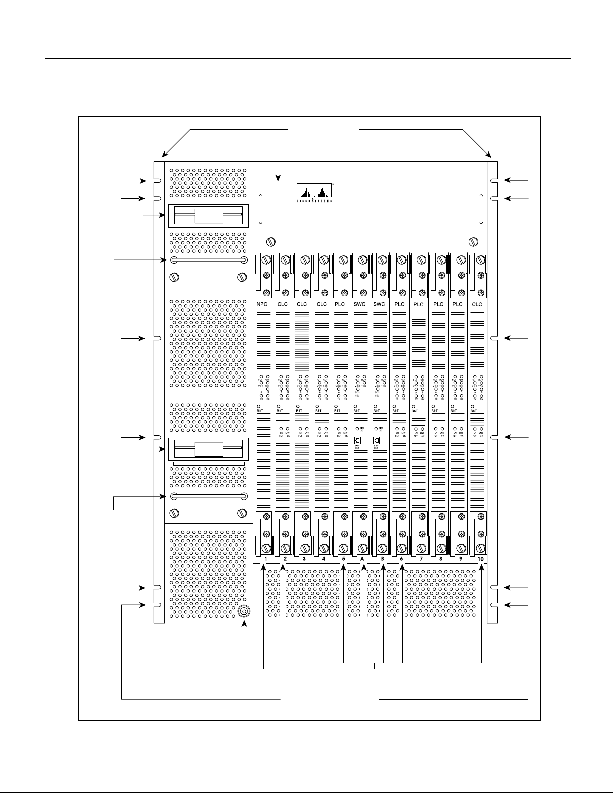
Figure 2-1 Front View of LightStream 2020 Chassis
Mounting flanges
Blower (behind cover)
Installing an LS2020 Switch in Rack
Disk assembly
Disk assembly
handle unsafe
for lifting!
Disk assembly
LightStream 2020
™
Disk assembly
handle unsafe
for lifting!
ESD jack
Line cardsNP card
cards
Slots for mounting screws
(12 places)
H4812
Line cardsSwitch
Installing a LightStream 2020 Switch 2-5
Page 6
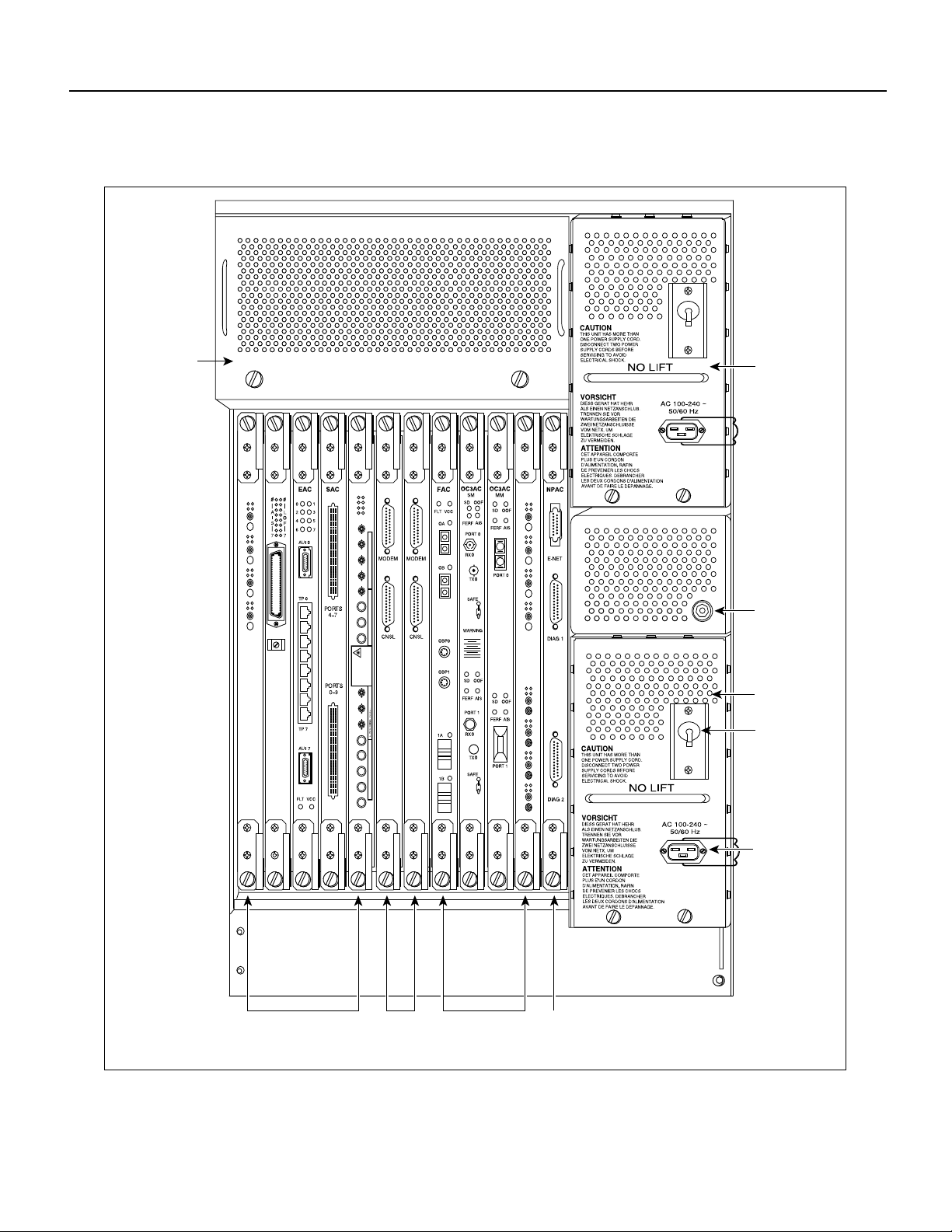
Installing an LS2020 Switch in Rack
Figure 2-2 Rear View of AC-powered LightStream 2020 Chassis
Blower (behind
cover)
T3AC
R
F
RX
TX
R
F
RX
TX
R
F
RX
TX
R
F
RX
TX
AC power tray
CEMAC
O
A
O
O
A
1
O
A
2
O
A
3
T1
FEAC
0
1
2
3
4
5
6
7
RX0
TX0
RX1
TX1
RX2
TX2
RX3
TX3
Warnhinweise fur den Gebrauch des Lasers sind im Installationshandbuch enthalten. Consulter le manuel d'installation au sujet de l'avertissement sur le laser.
NVISIBLE LASER RADIATION IS EMITTED FROM
WAVELENGTH: 850nm
MAXIMUM OUTPUT: 63.1 µW
CERTIFIED TO: EN 60 825:1994
THIS APERTURE.DO NOT STARE INTO BEAM OR
VIEW DIRECTLY WITH OPTICAL INSTRUMENTS.
CLASS 3A LASER PRODUCT.
I
RX4
TX4
RX5
TX5
RX6
TX6
RX7
Consulte el manual de instalacion para informarse sobre las advertencias relativas al laser.
TX7
E3AC
R
F
RX
TX
R
F
RX
TX
R
F
RX
TX
R
F
RX
TX
R
F
RX
TX
R
F
RX
TX
R
F
RX
TX
R
F
RX
TX
O
A
O
O
A
1
O
A
2
O
A
3
O
A
4
O
A
5
O
A
6
O
A
7
ESD jack
AC power tray
Power switch/
circuit breaker
I/O access
cards
2-6 LightStream 2020 Installation Guide
Console/
modem
assemblies
I/O access
cards
Power inlet
H4811
NP access
card
Page 7

Wiring a DC-Powered System
The procedure in this section explains how to wire a DC-powered LS2020 switch to a DC power
source. This task should be performed only by qualified service personnel or a licensed electrician.
This section applies only to systems with the DC power option. If you have a standard AC-powered
system, skip to the section “Installing Fantails.”
For general information on DC-powered LS2020 systems, see the LightStream 2020 Hardware
Reference and Troubleshooting Guide. For power specifications, see the LightStream 2020 Site
Planning and Cabling Guide.
Preparation for Wiring
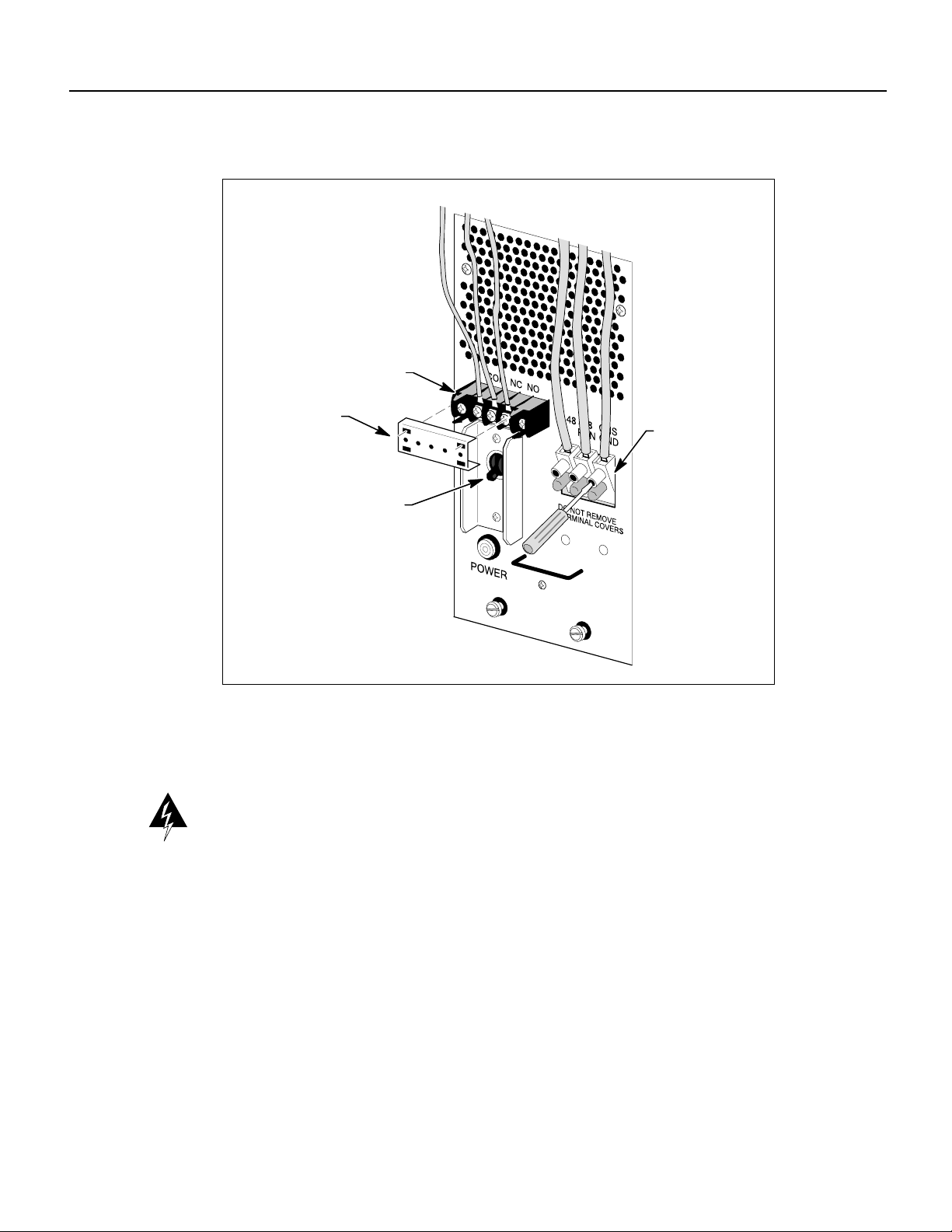
Note the following in preparation for wiring a DC-powered LS2020 switch:
• The system power connection on the DC power tray is provided by a 3-position terminal block,
as shown in Figure 2-3. The –48, –48RTN, and CHS GND connections providing –48VDC
power to the system require a minimum of number10AWG wire for the 24A-rated load. The
terminal block is rated to accept up to number 8AWGsolid wire. The use of ferrules to terminate
these wires is recommended.
• The alarm circuit connection to the DC power tray is provided by a smaller 3-position terminal
block, also shown in Figure 2-3. The COM, NO, and NC connections providing the circuit
breakeralarm indication shouldbe wired with number22AWG or largerwire. The use ofnumber
6 spade or ring lug terminals for these connections is recommended.
Wiring a DC-Powered System
• Obtain a slot-tip screwdriver for securing the system power terminals and a Phillips screwdriver
for securing the alarm circuit terminals.
Installing a LightStream 2020 Switch 2-7
Page 8
Wiring a DC-Powered System
Figure 2-3 Connections to DC-powered Chassis
Terminal block
for alarm circuit
Wiring Procedure
Warning The wiring task should be performed only by a licensed electrician or qualified service
personnel. Untrained personnel may be exposed to hazardous DC voltages.
Removable cover
Terminal block
for system power
Circuit breaker/
power switch
H3690
To wire a DC-powered LS2020 switch to a DC power source, perform the following steps:
Step 1 Ensure that the circuit breaker/power switch on each DC power tray is OFF.
Step 2 Ensure that power to the circuit to which you will connect the LS2020 switch is OFF.
Step 3 Connect the three system power wires to the LS2020 terminal block, using the slot-tipped
screwdriver to secure the terminals. Do not remove the terminal covers at the base of the
terminal block.
Step 4 To connect the alarm circuit, remove the plastic terminal block cover (see Figure 2-3) and
set it aside for the time being.
Step 5 Connect the alarm wires to the LS2020 terminal block, using the Phillips screwdriver to
secure the terminals.
Step 6 Replace the terminal block cover.
2-8 LightStream 2020 Installation Guide
Page 9

Step 7 Repeat the procedure above if the LS2020 switch contains a second DC power tray.
Step 8 Observe the green power LED on the front of the power tray when power is applied. If the
LED is not lit, check for incorrectly connected wires or problems in the DC power source.
Installing Fantails
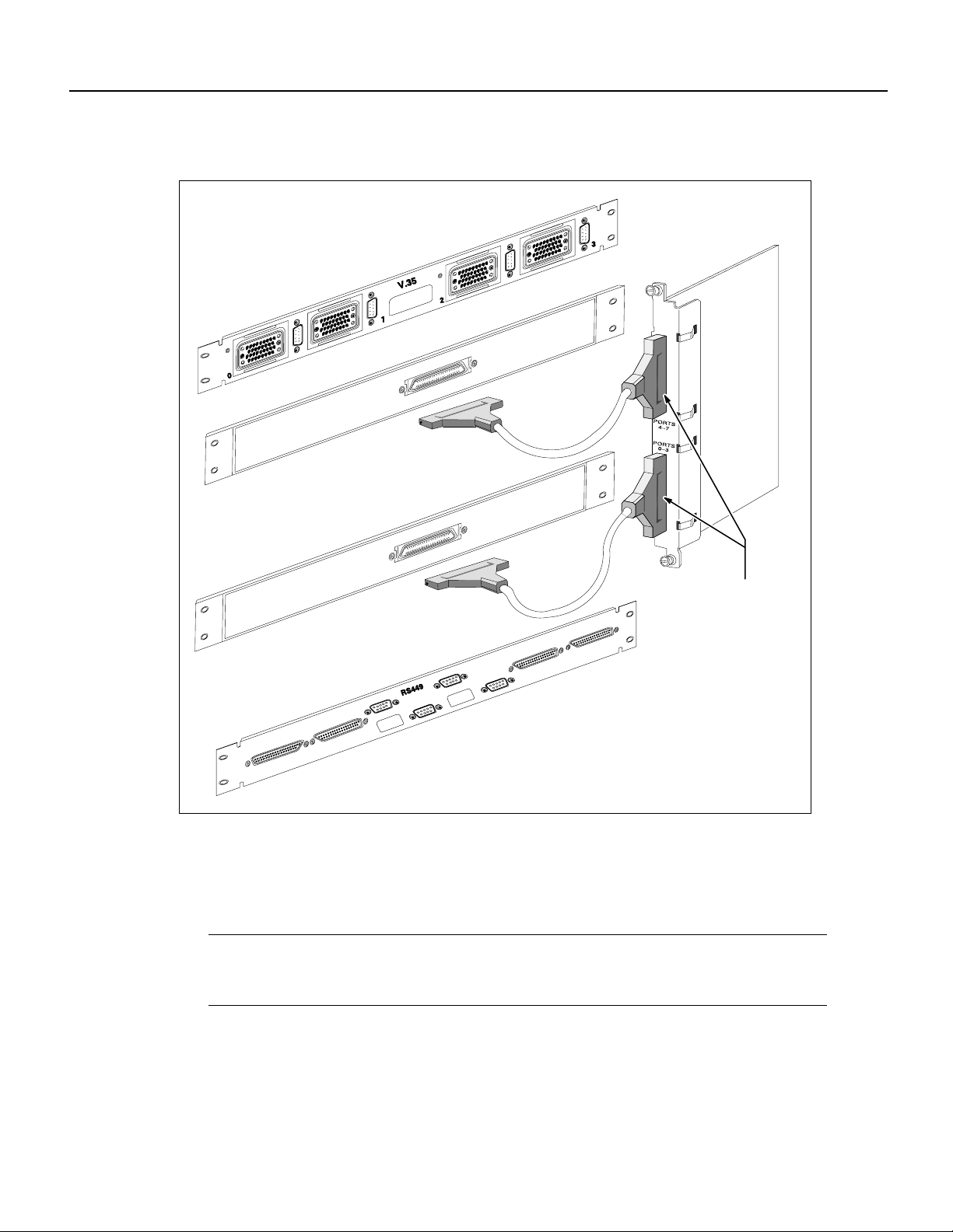
This section explains how to mount and connect fantails in your LS2020 switch (see Figure 2-4).
Fantailsprovide connectors for data cables on low-speed (V.35,X.21 and RS-449) lines and T3 lines
that are attached to cell line card/T3 access cards in an LS2020 switch.
If your system has no low-speed or cell line card/T3 modules, skip to the section “Attaching Data
Cables.”
Note RS-449 refers to a popular physical layer interface standard that is now called EIA/TIA-449.
However, to avoid confusion in this document, the “RS-449” nomenclature will be retained when
describing the components and capabilities of an LS2020 switch.
Required Tools and Equipment
Obtain the following equipment and tools in preparation for installing fantails:
Installing Fantails
• Fantails in the desired quantity (provided by Cisco Systems).
• Required fantail cables (provided by Cisco Systems).
• Fantail mounting screws,clip nuts, and washers (provided by Cisco Systems).If your equipment
rack has metric-threaded rails, you must provide appropriate mounting screws.
• A 5/16-inch slotted-tip screwdriver.
• Adhesive labels for making appropriate notations on each fantail.
• A grounding wrist strap for ESD protection during fantail installation.
Note If you are installing X.21 fantails and you plan to configure the ports as DTEs, you must
obtain and install a 15-pin male-to-male gender converteron each port in order to change the female
connector to a male connector. Note, however, that the gender converters are not required for X.21
ports configured as DCEs.
Installing a LightStream 2020 Switch 2-9
Page 10
Installing Fantails
Figure 2-4 Fantail Cable Connections
Low-speed
access card
V.35 fantail
Front view
Rear view
H3691
RS-449 fantail
Fantail Installation Procedure
To install fantails in your LS2020 switch, perform the following steps:
Note Before installing fantails, check the interface jumpers on each low-speed access card. These
jumpers must be set to the interface displayed on the fantail(s) for that card. For instructions on
setting interface jumpers, see the LightStream2020 Hardware Reference & TroubleshootingGuide.
Rear view
Front view
100-pin high-density
connectors support
four ports each
Step 1 Select a position on the rack to mount the fantail. Attach the four clip nuts provided with
the fantail to the appropriate holes in the rails.
Step 2 Put on the ESD wrist strap and connect it to the ESD jack on the rear of the LS2020 chassis.
2-10 LightStream 2020 Installation Guide
Page 11

Attaching Data Cables
Step 3 Attach the fantail cable(s) to the back of the fantail and the corresponding access card in
the chassis. (Performing this task now is recommended, rather than installing the fantail
first and having to reach behind it to attach the cable(s) to a connector that you cannot
observe directly.) Note that the cable is reversible; that is, either end of the cable can be
connected to the fantail. Exercise care to avoid suspending the weight of the fantail on the
cable.
Step 4 Attach the fantail to the rails with the mounting screws and washers provided, using a
slot-tip screwdriver.
Step 5 Label the fantail with the slot number or the name of the interface module to which the
fantail is connected.
Step 6 Repeat Step 1 and Steps 3 through 5 to install additional fantails in your LS2020 switch.
Note If you are mounting an X.21 fantail, set the DTE/DCE switches for each port to the desired
mode.(See the LightStream 2020 HardwareReferenceandTroubleshooting Guide for moredetailed
instructions on configuring X.21 ports as DTEs or DCEs.) If you select a DCE interface, note that
you must install a gender converter on each DTE port in order to change the female connector to a
male connector.
Attaching Data Cables
To attach data cables to your LS2020 switch, perform the following steps:
Step 1 If you have any FDDI cards in your LS2020 switch, install connector keys provided by the
cable vendor onto your FDDI cables. The keys make it impossible to attach a cable to the
wrong kind of connector on the FDDI card.
Step 2 If you have any OC-3c or FDDI cards in your LS2020 switch, remove and save the
protective covers on the ports that will be used. Leave any unused ports covered.
Step 3 If you have any E1 CEMAC cards (circuit emulation access cards) in your LS2020 switch,
check the user-settable jumper settings on the card(s). These jumpers allow you to select
termination impedance and grounding on the receive line, as well as the pulse amplitude
and grounding on the transmit line.
As default values, the termination impedance and pulse amplitude jumpers are set to 120
ohms, and the transmit and receive lines are not grounded. Use these default settings if you
plan to use the E1 CEMAC card without a fantail. However, if you do plan to use a fantail
(which provides 75-ohm interfaces), you must use 75-ohm settings for termination
impedance and pulse amplitude and set grounding to on.
For more detailed information about changing the E1 CEMAC card jumper settings,
consult the LightStream 2020 Hardware Reference and Troubleshooting Guide.
Step 4 Connect any available external data cables. (Refer to the LightStream 2020 Site Planning
and Cabling Guide fordetails about data cablesand connectors.) If youhaveEthernetcards
inyour LS2020 switch, notethateach card supports onlyeightports (0 through 7),although
10 physical connectors are available on the access card. Note also that youcan use onlyone
of the 10Base-T or AUI connections on ports 0 and 7.
Installing a LightStream 2020 Switch 2-11
Page 12

Closing the Chassis
Note For ease of maintenance, route cables at the back of the LS2020 chassis in a way that enables
you to later remove any access card without disconnecting cables attached to other access cards or
fantails.
Closing the Chassis
Before applying system power, check the front and back of the system to ensure that all boards,
disks, blowers, bulkheads, filler panels, and covers are in place and secured firmly to the chassis
frame. When in place, these items form an enclosure that serves three important functions:
• Prevents exposure to hazardous voltages and currents inside the chassis.
• Confines electromagnetic interference (EMI) within the chassis, a requirement for meeting EMI
standards. Emissions from an LS2020 switch that is not fully enclosed may interfere with other
ambient equipment.
• Maintains the flow of cooling air through the chassis. Air flow disturbances can result in thermal
problems that may induce electronic component failures.
Caution Do not operate an LS2020 switch without first ensuring that all components removed in
the installation procedure are restored to their original position in the chassis. The LS2020 switch
must be operated properly at all times to avoid exposure to hazardous voltages, to confine EMI
radiation within the enclosure, and to maintain the proper flow of cooling air through the chassis.
Applying System Power
You can power your LS2020 switch with either an AC or aDC power tray.In addition, you can equip
your LS2020 switch with an optional (redundant) power tray of like type (see Figure 2-5).
To power up an LS2020 switch, perform the following steps:
Step 1 If you have an AC-poweredsystem, plug one end of the power cord into the power inlet on
the power tray andplug the otherend into adedicated AC power outlet. Notethat the power
inlet on the rear panel has a wire bail latch for securing the power cord to the chassis. Flip
the AC power switch to the left of the power inlet to the up position.
If your system is equipped with a second AC power tray, repeat Step 1 for this tray.
Step 2 Ifyou havea DC-poweredsystem, flip the DCpowerswitchlocatedon the power tray panel
to the up position. (This step assumes that your LS2020 switch has already been connected
to a DC power source by qualified service personnel or a licensed electrician, as described
in the section “Wiring a DC-Powered System”).
If your system is equipped with a second DC power tray, repeat Step 2 for this tray.
2-12 LightStream 2020 Installation Guide
Page 13

Figure 2-5 LightStream 2020 AC and DC Power Trays
Applying System Power
Terminal
block
Power
switch
Terminal
block
Chassis with
DC power trays
Note When the LS2020 switch is powered up, the blowers start running and the test and control
system (TCS) applies powerto the cardsand initiates thepower-onself test (POST) sequence. LEDs
on the power tray(s) and the individual cards indicate operational status, as reflected in the flow chart
in Figure 2-6. The power-up sequence, including the POST, takes a minute or less.
Step 3 If the green ready (RDY) LED on each card lights up (indicating operational status),
proceed to the next section “Installing Modems.” If a yellow fault (FLT) LED stays lit on
any card, indicating the existence of a problem, do either of the following:
Power
switch
Chassis with
AC power trays
Power switch
Power inlet
Power switch
Power inlet
H3671
• Refer to the LightStream 2020 Hardware Reference & Troubleshooting Guide to
determine why the FLT LED indication occurred and how to correct it.
• Temporarily removethefaultycard from theLS2020 chassis andbring up the rest of the
system.
Installing a LightStream 2020 Switch 2-13
Page 14

Installing Modems
Figure 2-6 LightStream 2020 Power-up Sequence
Turn on
LS2020 power
Green LED on power
supply lights up
Blowers start running
Yellow FLT LED goes out;
green RDY LED lights up
Switch card master
runs shell;
NP boots itself
TCS powers up;
LEDs on
each card light up
Switch cards arbitrate
~5 seconds
to select master
Yes
POST
passes ?
No
TCS slaves enable power
on cards; VCC LEDs light
up to indicate local power
on each card
POST executes;
yellow FLT LED lights up;
green RDY LEDs blink on
each card while POST runs
Yellow FLT LED lights up;
green RDY LED goes out
H3692
Installing Modems
You should obtain and install a modem for each switch card in the LS2020 chassis. In the event that
an operational problem causes a node to be isolated from the rest of the network, the modem may
be the only means available for communicating with that node.
The modem connects to the modem port on the modem/console assembly bulkhead at the back of
the LS2020 chassis, using the modem cable described in the LightStream 2020 Site Planning and
Cabling Guide.
A modem attached to an LS2020 node must be a V.42 Hayes-compatible unit capable of operating
at 2400 baud. The following modems are compatible with the LS2020 switch:
2-14 LightStream 2020 Installation Guide
Page 15

• Zoom 9624V
• Zoom FXV (FXV9624V)
• Hayes SmartModem 2400 V.24
For information on the default modem port settings and how to change them, see the LightStream
2020 Network Operations Guide.
Basic LS2020 Configuration Tasks
This section explains how to enter basic configuration information for your LS2020 chassis in order
to make it operable in your networking environment and manageable from your NMS. You must
perform these procedures for the NP card(s) in your LS2020 chassis.
Note Ifyou experience a problem while performingbasicconfiguration tasks, you may needto shut
downand restart the system. Referto the LightStream2020 HardwareReference& Troubleshooting
Guide for instructions on performing an orderly shutdown.
Basic LS2020 Configuration Tasks
Required Configuration Information
Youneed to have at hand the followinginformationbeforebeginningthe LS2020 basic configuration
procedures:
• Passwords for the four default login accounts for the LS2020 switch: root, oper, npadmin, and
fldsup.
• Host name for the LS2020 node.
• IP address and subnet mask for the primary NP, as well as for the backup NP, if present.
• IP address and subnet mask for the NP Ethernet interface, if present.
• IP address of the default router for the LS2020 network. This IP address should be configured
only if the default router and the NP Ethernet interface are attached to the same LAN.
• Configuration information for one or more trunk ports on the node. For nodes not directly
connected to the NMS, the trunk port will be used to load a full LS2020 node configuration from
the NMS.
The following sections describe in greater detail the information required for basic LS2020
configuration.
Passwords
You must create a password for each of the four default login accounts on the LS2020 switch: root,
oper, npadmin, and fldsup. See the LightStream 2020 Network Operations Guide for more
information about default login accounts.
A password must be at least six characters in length. It can be as long as you wish, but only the first
eight characters are used. Any combination of characters is acceptable, including spaces.
Installing a LightStream 2020 Switch 2-15
Page 16

Basic LS2020 Configuration Tasks
Host Name
You must assign a unique host name to each LS2020node. Typically, a namecan be chosento reflect
the node’s geographic location (for example, Tokyo2) or its function within an organization (for
example, mfg3).
The name may consist of any combination ofletters and numbersup to 32 characters, butit must not
begin with a number. Thus, Pensacola23 is a valid host name, but 23Pensacola is not; similarly,
Pensacola.23 is not a valid name, since it contains a character other than a letter or number.
IP Addresses and Masks
For each LS2020 node, you must provide from one to four IP addresses and associated network
masks, as described below:
• Primary NP address and mask (for every LS2020 node in the network)
Nodes in an LS2020 network use their primary NP addresses to communicate network
management traffic to each another.
Note All NP addresses within the same LS2020 network must have the same network number,and
each node must have a unique host ID.
• Subnet mask for the primary NP address
The subnet mask specifies which portion of the IP address is the network number and which
portion is the host ID. This mask should be configured to be the same for all nodes in a given
LS2020 network.
• Secondary NP address, only if a backup NP is present in the chassis
If a node hasa second (backup) NP,the node usesits primary and secondaryNP addresses topass
network management traffic between the two NPs within the node. The primary NP address is
used by whichever NP is active.
Note All NP addresses within the same LS2020 network must have the same network number,and
each node in the network must have a unique host ID.
• Ethernet address and mask of the NP (when either the primary or secondary NP is connected to
an Ethernet LAN)
An Ethernet LAN may be attached to the NP for communicating network management traffic
between the node and the NMS. If an Ethernet LAN is connected to the NP, the NP’sEthernet IP
address must be configured. If a backup NP is present in the chassis, both NPs must be attached
to the same Ethernet segment. The NP’s Ethernet IP address is used by whichever NP is primary
(active).
Note This Ethernet IP address has the network number of the attached Ethernet LAN (which must
be different from the network number of the LS2020 network). The Ethernet IP address also has a
host number that is assigned by the Ethernet LAN administrator.
2-16 LightStream 2020 Installation Guide
Page 17

Basic LS2020 Configuration Tasks
• Subnet mask for the NP’s Ethernet address
The subnet mask for the NP’s Ethernet address specifies which portion of the IP address is the
network number and which portion is the host ID. This mask is the same for all nodes on the
Ethernet LAN attached to the primary NP. You can obtain the subnet mask from the Ethernet
LAN administrator.
• Default router (only if needed for reaching the NMS)
If an Ethernet LAN is attached to the primary NP, but the NMS is not directly connected to that
Ethernet LAN, a default router can be configured as the means for communicating network
management traffic between the NP and the NMS. The IP address for the default router has the
same network number as the attached Ethernet LAN (this number must be different from the
network number of the LS2020 network). The IP address for the default router also has a host
number assigned by the Ethernet LAN administrator.
If you plan to operate with a single physical LS2020 network under your network number and
the LS2020 network is a class C network, record 255.255.255.0 as the subnet mask. (For a class
B network without subnetting, record 255.255.0.0 as the subnet mask; for a class A network
without subnetting, record 255.0.0.0 as the subnet mask.)
Note Network management can also be accomplished by means of an Ethernet LAN connected to
an ordinary Ethernet data port (that is, an Ethernet access card port) on the LS2020 node. The NMS,
however, must be attched directly to that Ethernet LAN. In this case, do not configure the NP’s
Ethernet address or default router address. Furthermore, in the current release, to provide access
control over Ethernet ports that can be used by an NMS, a port configuration parameter has been
added which allows you to specify whether IP traffic destined for an NP is forwarded or blocked.
This configuration parameter, lsLanPortNPTrafficFilter, determines whether or not inbound frames
received on an Ethernet port are delivered to any NP in the network. The default value of this
parameter for all access card Ethernet LAN ports is to block IP traffic to an NP. Therefore, you must
explicitly set this parameter, on a port-by-port basis, to forward traffic to an NP. The Ethernet ports
on the NP access cards remain unaffected in the current release, that is, these ports always pass IP
traffic to the NP.
For detailed information about configuring Ethernet port attributes, see the LightStream 2020
Configuration Guide. For detailed information about IP addresses, subnet masks, and network
classes, see the LightStream 2020 Site Planning and Cabling Guide.
Trunk Port Information
For each trunk port that you configure, the following information is required:
• The trunk card type: low speed (T1/E1 rate), T3, E3, or OC-3c
• The number of the chassis slot in which the trunk card is located
• The port number (except on an OC-3c card, which has only one trunk port)
• Additional port information needed varies, depending on the type of port being configured, as
indicated below:
— For a low-speed trunk port, specify the DTE/DCE type and DTE or the DCE bit rates.
— For a T3 trunk port, specify the line type (C-bit parity or clear channel), the cable length (0
– 450 feet or 450 – 900 feet), and the cell payload scrambling mode (enabled or disabled).
Installing a LightStream 2020 Switch 2-17
Page 18

Basic LS2020 Configuration Tasks
— Foran E3 trunk port, specify the cable length (0 – 400feet, 300 – 1000 feet, 800 – 1300
feet, or 1100 – 1900 feet) and the cell payload scrambling mode (enabled or disabled).
— For an OC-3c trunk port, specify the clocking mode (internal or external).
For more information about trunk port configuration, refer to the LightStream 2020 Configuration
Guide.
TCS Hub Command Summary
The procedures in this chapter make use of the following TCS hub commands:
• reset <slot#> Resets the card in the specified slot.
• connect <slot#> Establishes a connection to the card in the specified slot
• show <sa | sb> Detects the baud rate for the specified switch.
• set <sa | sb> Sets the baud rate for the specified switch.
• init <sa | sb> modem Initializes the modem port on the specified switch.
These commands and their associated arguments are described in greater detail in this section
wherever the TCS hub commands are used in specific procedures.
Attaching a Terminal to Console Port
This section tells you how to attach a terminal to the console port of a Release 2 switch card. It also
tells you how to match the baud rate between the terminal and the console port on the switch card.
Required Equipment
You need the following equipment to perform the procedures in this section:
• VT100 terminal (or equivalent)
• Terminal cable
Background Information
Prior to Release 2.1 of the LS2020 platform software, the TCS hub code for a Release 2 switch card
(SC2) supported baud rate selection for both the console and modem ports through what was called
the “BREAK” detection mechanism (also referred to as the “auto-baud” or “pseudo-auto-baud”
mechanism). Use of this mechanism, which involvedmultiple activations of the Break keyfor baud
rate selection, is no longer supported. Under this previous scheme, the midplane EEPROM locations
used to maintain the console and modem port baud rates were “reserved” and, hence, not initialized
with appropriate default values.
Now, when new TCS hub code is installed in a Release 2 switch card that has not had these
“reserved”locations initialized, the new code evaluates the contentsof these EEPROM locations and
initializes them, if required, with appropriate default values. See the section below entitled “Setting
Console/Modem Baud Rates through TCS Hub Commands” for these default values and the order
of precedence for other possible baud rates for the console and modem ports.
2-18 LightStream 2020 Installation Guide
Page 19

Setting Console/Modem Baud Rates through TCS Hub Commands
To detect and set baud rates for the console and modem ports for Release 2 switch cards, you use the
TCS hub show and set commands, respectively. These commands interpret and manipulate the
contents of specific fields in the midplane EEPROM used for storing initialized baud rates for the
console and modem ports.
Note Baud rate detection and selection for the console and modem ports apply only to Release 2
switch cards.
The general form of the TCS hub show command for baud rate detection is outlined below:
TCS hub<<A or B>> show <sa | sb> <console | modem> baudrate
where:
TCS hub<<A or B>> Is the TCS hub prompt for the switch card (either switch card A or B, as
appropriate).
show Is the command that operates in conjunction with command arguments to
display the baud rate for the specified switch and the specified port.
Basic LS2020 Configuration Tasks
<sa | sb> Denotes that the show command is to apply to switch card A or B,
whichever is specified.
<console | modem> Denotes that the show command is to apply to the console port or the
modem port, whichever is specified.
baudrate Displays the baud rate for the specified port.
The general form of the TCS hub set command for baud rate selection is outlined below:
TCS hub<<A or B>> set <sa | sb> <console | modem> baudrate <rate>
where:
TCS hub<<A or B>> Is the TCS hub prompt for the switch card (either switch card A or B, as
appropriate).
set Is the command that operates in conjunction with command arguments to
set the baud rate for the specified switch and the specified port.
<sa | sb> Denotesthat the set command is to applyto switch card A orB, whichever
is specified.
<console | modem> Denotesthat the set command is to apply tothe console port orthe modem
port, whichever is specified.
baudrate Indicates that the set command is to setthe baud rate forthe specified port.
<rate> Defines the actual baud rate for the specified port.
The following is the order of precedence of the baud rate for the modem
port on a Release 2 switch card:
2400 (default value)
9600
The following is the order of precedence of the baud rate for the console
port on a Release 2 switch card:
9600 (default value)
19200
Installing a LightStream 2020 Switch 2-19
Page 20

Basic LS2020 Configuration Tasks
2400
1200
4800
38400
300
Note The console port baud rate can be changed at any time, but the change will take effect only
on power-up of the LS2020 chassis or a reset of the applicable switch card. Similarly, the modem
port baud rate can be changed at any time, but the change will take effect only on power-up of the
LS2020 chassis, areset of the applicable switch card, or when the modem port is reinitializedvia the
TCS hub init command.
Changing Modem Port Baud Rate if Modem Connection Cannot Be Established
If the modem port on a Release 2 switch card (SC2) is initialized with a baud rate other than that
with which the modem can operate, you can change the modem port baud rate through either of two
methods, whichever is appropriate for your LS2020 configuration:
• Method 1 – Changing modem baud rate locally—This method requires access to the local
console of your LS2020 switch.
• Method 2 – Changing modem baud rate through use of redundant components—This
method assumes that the local console terminal is not available, such as when a software
installation or upgrade is being done remotely. It also assumes that your LS2020 chassis is
equipped with redundant Release 2 switch cards and modems, and that you have the ability to
dial into the LS2020 chassis using the other switch card and modem.
Method 1
If you have access to the local console, perform the following procedure to match the modem port
baud rate:
Step 1 Issue the set command from the console, as shown below:
set {sa | sb} modem baudrate {2400 | 9600}
where {sa | sb} represents either Release 2 switch card A or B, as appropriate, and
{2400 | 9600} represents the available choices in matching the modem port baud rate.
Step 2 Issue the init command at the TCS hub prompt:
init {sa | sb} modem
This command initializes the modem port on the specified switch card with the selected baud rate.
Method 2
If you do not have access to the local console, but you can dial into the LS2020 chassis by means of
a switch card, perform the following procedure to match the baud rate of the desired modem port:
Step 1 Dial into the LS2020 chassis and determine the address of the switch card to which the
desired modem is attached, that is, the modem for which you are attempting to match the
baud rate.
2-20 LightStream 2020 Installation Guide
Page 21

Step 2 Issue the set command at the TCS hub prompt, as shown below:
set {sa | sb} modem baudrate {2400 | 9600}
In this command, specify the switch card having the non-matching baud rate. Forexample,
if you have dialed into the LS2020 chassis through switch card A, specify sb in the set
command; if you have dialed into the chassis through switch card B, specify sa in the set
command. Finally, specify the desired baud rate for the modem port.
Step 3 Issue the init command at the TCS hub prompt, as shown below:
init {sa | sb} modem
Again, as in Step 2 above,specify the switch card having the non-matching baud rate. This
command initializes the modem port on the switch card with the specified baud rate .
Attaching a Terminal and Matching the Baud Rate
Figure 5-2 in the chapter entitled “Installing Additional Components” illustrates the console/
modem assembly for a switch card. This assembly is inserted in the access (rear) side of the LS2020
chassis opposite a corresponding switch card. This assembly provides the means for attaching a
terminal or a modem to your LS2020 switch.
To attach the terminal cable to the console port and to match the terminal and the console port baud
rates, perform the following procedure:
Basic LS2020 Configuration Tasks
Step 1 Connect the cable for the VT100-compatible terminal to the console (CNSL) port on the
console/modem assembly.
The switch card slots in the front of the LS2020 chassis are labeled A and B, as are the
corresponding slots for the console/modem assembly bulkhead(s)in the rearof the LS2020
chassis. If the primary TCS hub is on switch card A, connect the terminal cable to the
console port of the bulkhead in rear slot A; similarly, if the primary TCS hub is on switch
card B, connect the terminal cable to the console port of the bulkhead in rear slot B.
Note If your LS2020 chassis contains two switch cards, connect the terminal cable to the console
port on the console/modem assembly for the switch card with the primary TCS hub.To identify this
card, examine the green TCS SEL LED on each switch card. The card with the TCS SEL LED lit
is the primary TCS hub.
Step 2 Press the Return key on the terminal keyboard.
If the TCS hub<<A or B>> prompt appears, or if some other prompt appears (see the Note
below), after you press the Return, the prompt signifies agreement between the terminal
baud rate and the console port baud rate and that the terminal is properly attached.
Note If the baud rates match, the system may respond with other than the TCS hub<<A or B>>
prompt, depending on the card to which a connection exists. For example, if you had previously
established a connection to an NP card via the TCS connect command, the system would respond
with the bash (#) prompt, rather than the TCS hub<<A or B>> prompt. The appearance of any valid
system prompt on the terminal screen after Return key activation signifies baud rate agreement.
Installing a LightStream 2020 Switch 2-21
Page 22

Basic LS2020 Configuration Tasks
When the system verifies itself as being responsive (through the return of an appropriate
prompt), you can then make the terminal fully operational in your LS2020 environmentby
connecting it to the NP.Todo so, proceeddirectly to the sectionbelowentitled“Connecting
the Terminal to the NP.”
However, if the system does not respond at all, or if screen output is garbled after you press
the Return key, one of the following conditions may pertain:
• An apparent mismatch of the terminal and the console port baud rates exists. Such a
• A connection may exist to a non-operational card or a card that has been physically
Step 3 Issue the character sequence ‘. (back quote plus dot, that is, left single quote plus period)
at the terminal keyboardand pressthe Return key.This actionbreaksthe connection which
may exist between the switch card and any non-operational or missing card.
If a valid system prompt does not appear following Return key activation, a baud rate
mismatch still exists and you must continue with Step 4.
mismatch may occur, for example, if the console port has been initialized previously
with a baud rate different from that of the terminal.
In this case, you must attempt to achieve a baud rate match by continuing with Step 4
below.
removed from the system, but to which a logical connection still exists.
In this case, proceed with Step 3 below.
Step 4 For baud rate matching purposes, your LS2020 chassis must be equipped with at least one
switch card and a terminal.
Set the terminal to a new baud rate, using the order of precedence defined for the console
port in the section above entitled “Setting Console/Modem Baud Rates through TCS Hub
Commands.”
Step 5 Press the Return key on the terminal.
Step 6 If the baud rates match after you press the Return key, the TCS hub prompt is displayed,
indicating that the terminal is properly attached.
Proceed to the section below entitled “Connecting the Terminal to the NP.”
However, if the TCS hub prompt is not displayed, you must repeat Step 4 and Step 5 until
a match with one of the defined baud rates is achieved.
If the terminal does NOT support one of the defined console port baud rates, proceed with
Step 7 below.
If you cycle through all the possible console baud rates without achieving a match, an error
condition exists. In this case, contact your Cisco Systems customer support representative.
Step 7 For baud rate selection, this step requires that your LS2020 be equipped with a modem
attached to the same switch as the terminal and that you have the ability to dial into the
LS2020 chassis.
If you can dial into the LS2020 chassis, do so. Then continue with Step 8 below.
If you are unable to dial into the chassis, skip to Step 10 below.
Step 8 Use the TCS hub set <switch slot> console baudrate <rate> command to set the
baud rate of the console port to agree with that of the terminal you are attempting to attach.
Step 9 Reset the applicable switch card.
This action reinitializes the console port to the baud rate selected in Step 8 above.
2-22 LightStream 2020 Installation Guide
Page 23

Basic LS2020 Configuration Tasks
Proceed to the section below entitled “Connecting the Terminal to the NP.”
Step 10 For baud rate selection, this step requires that your LS2020 chassis be equipped with two
switch cards. It also assumes that you can communicate with the switch card that currently
needs no baud rate adjustment.
Dial into this card via its modem port or use the terminal attached to its console port to set
the baud rate, as instructed in Step 11 below.
However, if your LS2020 chassis does NOT contain redundant switch cards, or if neither
switch card is accessible via its console or modem port, an error condition exists. In this
case, contact your Cisco Systems customer support representative.
Step 11 Use the TCS hub set <“other” switch slot> console baudrate <rate> command to
set the console port baud rate for the “other” switch card to agree with the baud rate of the
terminal you are attempting to attach.
Step 12 Reset the “other” switch card manipulated in Step 11 above.
This action reinitializes the console port to the baud rate selected in Step 11 above.
Proceed to the section below entitled “Connecting the Terminal to the NP.”
Connecting the Terminal to the NP
Note This procedure assumes that you have already attached a terminal to the Release 2 switch
card, as described in the preceding section entitled “Attaching a Terminal and Matching the Baud
Rate.”
To connect aterminal to the NPin your LS2020 switch,perform the procedure below. For simplicity,
this procedure assumes that you are using the NP in slot 1.
Step 1 Issue the following command at the TCS hub prompt to reset the NP to a running state:
TCS hub<<A>> reset 1
Step 2 Issue the following command at the TCS hub prompt to connect to the NP that you want to
configure:
TCS hub<<A>> connect 1
Step 3 When you connect to the NP, part or all of the following countdown sequence is displayed
on your screen. Do not press the Return key; allow the boot sequence to continue.
System will boot in 5 seconds: hit <RETURN> to interrupt.
System will boot in 4 seconds: hit <RETURN> to interrupt.
System will boot in 3 seconds: hit <RETURN> to interrupt.
System will boot in 2 seconds: hit <RETURN> to interrupt.
System will boot in 1 seconds: hit <RETURN> to interrupt.
The screen displays for the boot sequence then continue as shownin Step 1 in the section “Entering
Configuration Data” later in this chapter. However, before proceeding with the entry of required
configuration data, note the following special consideration about running configuration scripts.
Installing a LightStream 2020 Switch 2-23
Page 24

Basic LS2020 Configuration Tasks
Special Consideration: Running Scripts Separately
When you enter configuration data, two scripts are invoked automatically that prompt you for basic
configuration information (seebullets below). If youerr in entering information in response to script
prompts, you can run the scripts again separately.Todo so, enter the name of the script you want to
run at the bash# (root) prompt or the single-user ($) prompt.
• /bin/settimezoneinfo—Sets the time, date, daylight savings method, and time zone.
• /usr/app/base/bin/setsnmpconfig—Sets the host name, the IP address, the Ethernet IP address,
and the default router IP address. Also sets up trunk ports so that a complete configuration can
be downloaded from the NMS to a target LS2020 node.
Note These configuration scripts are intended for use only during the installation process.
When you run these scripts from the command line, theybehavevery much as theydo in thescripted
configuration procedure. However, one difference of note is that the setsnmpconfig command
checks for the presence of configuration files. (Normally,these files are not present during a typical
installation of a new LS2020 switch). If the system finds such files, it asks if you want to continue,
as shown below:
Configuration information already exists. If you continue, the configuration
information on this network node will be destroyed by overwriting the
following files:
/usr/app/base/config/configure.netdb
/usr/app/base/config/mma.db.dir
/usr/app/base/config/mma.db.pag
Continue? (y/n) [n]
Caution If you answer y (yes) to this query, the system overwrites the existing configuration files
for this particular LS2020 node, effectively deleting the files.
If configuration files are present and you choose not to overwrite them, the setsnmpconfig script
cannot continue. Instead, the script exits and returns you to the command line.
If configuration files arenot present,oriftheyarepresentand you choose to overwrite them, ascript
prompts you to enter network configuration information, as outlined in the following section,
“Entering Configuration Data.”
Entering Configuration Data
In this procedure, a script prompts you to enter basic LS2020 configuration information. In
performing this procedure, it is assumed that you have already initiated the boot sequence, as
previously described in the section “Connecting the Terminal to the NP.”
Note If a problem occurs with the LS2020 hard disk or the platform software, an error message is
displayed in lieu of the system output shown in Step 1 below. In this case, refer to the LightStream
2020 Network Operations Guide for instructions about reloading the LS2020 platform software.
Step 1 Observe the system’s boot display:
2-24 LightStream 2020 Installation Guide
Page 25

Basic LS2020 Configuration Tasks
**** LynxOS is down ****
***booting: drive:0, partition:0, kernel:”lynx.os”, flags:0x4308
Resetting SCSI bus
Kernel linked for 0xea010000
LOAD AT 0x10000
471040+40960+136260[61824+50608]
TOTAL SIZE: 745080 at 0x1001c
START AT 0x10020
NP memory size: 32 MB
ILACC: EEPROM enet addr:8:0:8:0:14:25, Silicon Rev:0x5, IB:0xea146620
virtual console: IB: 0xea139d20
NCR 53C710: Chip Revision: 0x2, IB: 0xec13d000
LynxOS/68040-MVME167 Version 2.1.0
Copyright 1992 Lynx Real-Time Systems Inc.
All rights reserved.
LynxOS release 2.1.0, level 1: NP-LynxOS #57: compiled Oct 05 1993 12:38:19
LynxOS Startup: ma
fsck /dev/sd0a
(all sizes and block numbers in decimal)
(file system creation time is Tue May 4 20:07:12 1993)
checking used files
recovering orphaned files
making free block list
making free inode list
43967 free blocks 3343 free inodes
fsck /dev/sd0b
(all sizes and block numbers in decimal)
(file system creation time is Tue May 4 20:07:33 1993)
checking used files
recovering orphaned files
making free block list
making free inode list
54194 free blocks 3633 free inodes
fsck /dev/sd0c
(all sizes and block numbers in decimal)
(file system creation time is Tue May 4 20:07:53 1993)
checking used files
recovering orphaned files
making free block list
making free inode list
49658 free blocks 3698 free inodes
fsck /dev/sd0d
(all sizes and block numbers in decimal)
(file system creation time is Tue May 4 20:08:11 1993)
checking used files
recovering orphaned files
making free block list
making free inode list
69884 free blocks 4434 free inodes
mounting all filesystems
Starting VM System ... Virtual Memory Engaged!
Step 2 Enter appropriate time and date information, as prompted by the system:
The timezone information for this system has not been configured!
Set the daylight savings and time zone information? (y/n) [y] y
Installing a LightStream 2020 Switch 2-25
Page 26

Basic LS2020 Configuration Tasks
Set the daylight savings method to one of the following values:
0 (no daylight savings)
1 (USA)
2 (Australia)
3 (East Europe)
4 (Central Europe)
5 (Western Europe)
Daylight savings method: 1
Set the timezone by specifying the number of minutes west of Greenwich
Examples:
300 (US Eastern Time)
360 (US Central Time)
420 (US Mountain Time)
480 (US Pacific Time)
Minutes west of Greenwich, England: 300
At the prompt, enter a new date or press <RETURN> to continue.
The date is set to Tue May 4 16:04:57 EDT 1993
Enter date (yymmddhhmm[.ss]: 9305041607
At the prompt, enter a new date or press <RETURN> to continue.
The date is set to Tue May 4 16:07:00 EDT 1993
Enter date (yymmddhhmm[.ss]: Return
(The second Enter date prompt confirms the initial date entry.)
Note If your LS2020 switch contains two NPs, ensure that their respective clocks agree to within
1 minute. If the clocks differ by more than 1 minute, the software that synchronizes files between
the two NPs may not operate properly.
Step 3 Enter passwords for the four default login accounts for the LS2020 switch. For each
account, enter y, then enter the password twice, as shown below:
The following accounts do not have passwords:
root fldsup npadmin oper
Install a password on the root account? (y/n) [y] y
Enter new password:
Retype new password:
Install a password on the fldsup account? (y/n) [y] y
Enter new password:
Retype new password:
Install a password on the npadmin account? (y/n) [y] y
Enter new password:
Retype new password:
Install a password on the oper account? (y/n) [y] y
Enter new password:
Retype new password:
Step 4 Enter the network management configuration information for the LS2020 switch, as
requested in the following configuration script. (Note that the Host Name and the IP
addresses shown in bold typeface in the script below are for illustrative purposes only; you
must supply an actual name and real IP addresses in these fields.)
2-26 LightStream 2020 Installation Guide
Page 27

Basic LS2020 Configuration Tasks
Note For an LS2020 switch with two NPs, you must perform this procedure twice—once for each
NP. You must enter identical information for each NP. Do not reverse the active and secondary IP
addresses on the second NP; theseaddresses are assignedto the entirechassis, not toindividual NPs.
If you do not enter the same information for both NPs, your LS2020 switch will not work.
The minimum network management information has not been configured!
Create a minimal network management configuration? (y/n) [y] y
Specify the host name for this network node.
Host name: LightStream1
You must allocate a subnetwork address for the internal network that connects all
network processors in your network. Configure the Chassis Primary (Active) IP address
for use within that subnet.
Chassis Primary (Active) IP Address [a.b.c.d]: 192.1.1.11
Configure the IP subnet mask for the internal network that connects all network
processors in your network.
Chassis Subnet Mask [a.b.c.d]: 255.255.255.0
Does the chassis contain redundant network processors (Y/N)? [N] N
If you answerY to this query,proceed to Step5. Otherwise, continue with theconfiguration
script as follows:
Your system may be attached to an external Ethernet LAN by means of the on-board
Ethernet LAN interface on the network processor.
If the network processor is attached to an Ethernet LAN, you will be asked to provide
the IP address and IP subnet mask of the network processor’s on-board Ethernet LAN
interface.
Is the network processor attached to an Ethernet LAN (Y/N)? [N} Y
Configure the IP address for the network processor’s Ethernet LAN interface.
Network Processor Ethernet IP Address [a.b.c.d]: 197.112.23.11
Configure the IP subnet mask for the network processor’s Ethernet LAN interface.
Network Processor Ethernet IP Mask [a.b.c.d]: 255.255.255.0
Is there an IP router on the attached Ethernet LAN (Y/Y)? [N] Y
Configure the Default IP router on the network processor’s Ethernet LAN interface.
Network Processor Ethernet Default IP Router [a.b.c.d]: 197.112.23.1
CHASSIS INFORMATION
Host Name: LightStream1
Chassis Primary (Active) IP Address: 192.1.1.11
Chassis Secondary IP Address: <none>
Chassis Subnet Mask: 255.255.255.0
Network Processor Ethernet IP Address: 197.112.23.11
Network Processor Ethernet IP Mask: 255.255.255.0
Installing a LightStream 2020 Switch 2-27
Page 28

Basic LS2020 Configuration Tasks
Network Processor Default IP Router: 197.110.175.2
Chassis configuration contains 1 network processor.
Network processor’s on-board Ethernet LAN interface is attached to an external
Ethernet LAN.
Is the chassis and network processor information correct? (Y/N)? [Y] Y
If you confirm that the configuration data you have entered in this step is correct by
responding Y to this query, the script continues with the trunk port configuration query
below.
On the other hand, if you wish to change any configuration data, answer “N” at the chassis
and network processor information query and repeat this step in its entirety. You will be
prompted by the configuration script to re-enter all the applicable network management
information for your LS2020 switch.
Configure trunk port information (Y/N)? [N] N
Creating minimum configuration database...done.
Similarly,if you respond N tothe above trunk port configuration query, the system reports
that it is creating a minimum configuration database and that you have completed the basic
configuration procedure.
If you respond “Y” to the trunk port configuration query, proceed with Step 6 below.
Step 5 If your LS2020 switch contains a redundant network processor, continue with the
configuration script, as follows:
Does the chassis contain redundant network processors (Y/N)? [N] Y
Configure the Chassis Secondary IP address (for use by a network processor
while acting as backup). This address should be an address on the subnetwork
connecting all network processors in your network.
Chassis Secondary IP Address [a.b.c.d]: 192.1.1.12
Your system may be attached to an external Ethernet LAN by means of the
on-board Ethernet LAN interface on the network processors.
In a redundant configuration with two network processors, if the network
processors are each attached to an external Ethernet LAN by means of the
on-board Ethernet LAN interfaces, the two network processors should each be
attached to the same Ethernet LAN.
If the network processors are attached to an Ethernet LAN, you will be asked
to provide the IP address and IP subnet mask of the network processors'
on-board Ethernet LAN interface.
Are the two network processors attached to an Ethernet LAN (Y/N)? [N] Y
In a redundant configuration with two network processors, the primary
(active) network processor provides the logical connection to the attached
Ethernet LAN. Thus you will be asked to specify only one IP address and mask.
Configure the IP address for the network processors' Ethernet LAN interface.
Network Processor Ethernet IP Address [a.b.c.d]: 197.112.23.12
Configure the IP subnet mask for the network processors' Ethernet LAN
interface.
2-28 LightStream 2020 Installation Guide
Page 29

Basic LS2020 Configuration Tasks
Network Processor Ethernet IP Mask [a.b.c.d]: 255.255.255.0
Is there an IP router on the attached Ethernet LAN (Y/N)? [N] Y
Configure the Default IP router for the network processors’ Ethernet LAN
interface.
Network Processor Ethernet Default IP Router [a.b.c.d]: 197.112.23.1
CHASSIS INFORMATION
Host Name: LightStream1
Chassis Primary (Active) IP Address: 192.1.1.11
Chassis Secondary IP Address: 192.1.1.12
Chassis Subnet Mask: 255.255.255.0
Network Processor Ethernet IP Address: 197.112.23.12
Network Processor Ethernet IP Mask: 255.255.255.0
Network Processor Default IP Router: 197.112.23.1
Chassis configuration contains 2 redundant network processors.
Network processors' on-board Ethernet LAN interfaces are attached to an
external Ethernet LAN.
Is the chassis and network processor information correct? (Y/N) [Y] Y
If you confirm that the configuration data you have entered in this step is correct by
responding Y to this query, the script continues with the trunk port configuration query
below.
On the other hand, if you wish to change any configuration data, answer “N” at the chassis
and network processor information query and repeat this step in its entirety. You will be
prompted by the configuration script to re-enter all the applicable network management
information for your LS2020 switch.
Configure trunk port information (Y/N) [N] N
Creating minimum configuration database...done.
Similarly,if you respond N to the above trunk port configuration query, the system reports
that it is creating a minimum configuration database and that you have completed the basic
configuration procedure.
However, if you respond Y to the trunk port configuration query,proceed with Step 6 below.
Step 6 If your LS2020 switch isnot directly attached to a LAN to which theNMS is also attached,
you must configure a trunk so that SNMP configuration traffic can flow between the new
LS2020 switch, the LS2020 network at large, and the LS2020 switch attached to the NMS.
Inoperational terms, the trunkport will be usedto load a fullconfigurationoverthe LS2020
network.
The trunk port configuration parameters you specify depend on thetype of trunkport that youintend
to use for SNMP configuration traffic. For detailed information about the various trunk port
configuration parameters supported by the LS2020 switch, refer to the chapter in the LightStream
2020 Configuration Guide that describes “port attributes.”
However, for the sake of example, a trunk port for a low-speed card has been selected to
demonstrate the trunk port configuration procedure. In this particular case, proceed as
directed by the following configuration script:
Configure trunk port information (Y/N) [N] y
Trunk Card Type:
Installing a LightStream 2020 Switch 2-29
Page 30

Basic LS2020 Configuration Tasks
1) Low Speed
2) T3
3) E3
4) OC3
Specify the trunk card type (1-4): 1
Specify the trunk card slot number (1-10): 3
Specify the port number (0-7): 0
DCE/DTE Type:
1) DCE
2) DTE
Specify the DCE/DTE type (1-2): 1
DCE Bit Rate:
Specify the DCE Bit Rate (1-15): 1
TRUNK INFORMATION
Type: Low Speed Trunk Slot: 3 Port: 0
DCE/DTE Type: DCE
DCE Bit Rate: 128 (kbps)
1) 128 Kb 5) 448 Kb 9) 1344 Kb 13) 3584 Kb
2) 192 Kb 6) 512 Kb 10) 1536 Kb 14) 4000 Kb
3) 256 Kb 7) 768 Kb 11) 1792 Kb 15) 5376 Kb
4) 384 Kb 8) 896 Kb 12) 2688 Kb
Is the port information correct? (Y/N) [Y] Y
As with chassis information, if you answer N to the port confirmation prompt, you will be
prompted to re-enter all the trunk port information, beginning with the “Trunk Card
Type
.”
If you answer Y, you will be queried if you want to configure an additional trunk, as shown
below:
Configure additional trunk port information (Y/N)? [N] Y
If you respond Y to this query, repeat this procedure to configure additional trunk ports.
If you respond N to this query, the system responds with the following message:
Creating minimum configuration database...done.
A trunk configuration CLI script has been written to /tmp/trunkconfig.cli
The message means that the system has created a minimum LS2020 configuration. It also
signifies that the system is loading the line cards, starting the LS2020 platform software,
and starting the neighborhood discovery process.
At this point, the login prompt appears. You can then continue with Step 7.
Step 7 If you have previously configured trunk port information as part of the basic configuration
procedure, you must apply that information to the platform software.
Note To apply trunk port informationto the platformsoftware, you mustfirst wait forthe line cards
(whichincorporate the trunk portsyou need to configure)tocome up. A linecard is signaled asbeing
up when the NDD_3 trap for that card appears on the console, as shown in the example below.
(OPER) NDD_3 at 06/26/95 10:56:04 EDT (06/26/95 14:54:04 GMT)
2-30 LightStream 2020 Installation Guide
Page 31

Basic LS2020 Configuration Tasks
Line Card ls2020:5 (MS-TR) up.
Next,log in to the system and start the CLI using the oper or npadmin account, as shown
in the example below:
user name: npadmin
password: <password> Return
When you log into the oper or npadmin account, the CLI starts automatically, first
presentingthe CLI banner ontheconsole and then theCLIprompt, as shown in the example
below:
cli: (ls_main) compiled Jul 26 1995 @ 03:45:21
Copyright 1995. Cisco Systems, Inc. All Rights Reserved.
cli>
When the CLI prompt appears, enter the CLI protected mode, as shown below:
cli> protected
Enter Password: <password> Return
*cli>
Next, invoke the CLI configuration trunk script using the source command, as shown
below:
*cli> source “/tmp/trunkconfig.cli”
This command applies the trunkconfiguration to the trunk ports you haveconfigured. Note
that additional traps may be generated at this time to signal the changes in the status of the
trunk ports. Such trap messages are normal.
Step 8 If you are installing a new LS2020 switch with two NPs, return to the earlier section
Upon completion of the basic configuration procedures for the NP(s) in your LS2020 chassis,
continue as described in the following section, “How to Proceed.”
How to Proceed
This section describes actions you should take after installing a new LS2020 switch.
Running Diagnostics
To ensure that the newly installed LS2020 switch is working properly, run the hardware diagnostics
described in the LightStream 2020 Hardware Reference & Troubleshooting Guide.
Starting Maintenance Log
Keepa maintenance log for each LS2020 switch in your network. At a minimum, you should record
the following information:
• The node name and its IP address
• Passwords
• The date and description of every maintenance or repair procedure performed on the LS2020
switch, such as replacement of a faulty line card, power tray, and so forth.
“Connecting the Terminal to the NP.” Repeat the configuration procedures from that point
to configure the second NP for your LS2020 switch.
• The chassis ID, modem initialization string, and modem password, all of which are stored in
EEPROMs on the midplane.
Installing a LightStream 2020 Switch 2-31
Page 32

Basic LS2020 Configuration Tasks
If the current EEPROMs or the midplane are replaced, you will need to enter the chassis ID and
modem information into the EEPROMs on the new midplane. See the LightStream 2020
Hardware Reference & Troubleshooting Guide for instructions on finding the chassis ID and
modem information.
You are also advised to record any unusual LS2020 behavior. The maintenance log can be highly
useful in identifying and correcting chronic or intermittent LS2020 operational problems.
Installing StreamView Network Management Software
You must install the CLI, the LS-Monitor, the LS-Configurator, the LS-Topology Map, and the
private MIB database on the NMS that you will be using to manage your LS2020 network. The
chapter “Installing StreamView Software” presents the procedures for installing this network
management software.
Setting Up Network Environment
The chapter “LightStream 2020 Setup Procedures” presents procedures and options that enable you
to tailor your networkenvironment to your particular operating requirements. For example, you can
enable the security mechanism that prevents unauthorized network access. Also, you can change
operational parameters, such as the default SNMP community name(s) and the default trap delivery
address(es).
You should read the chapter “LightStream 2020 Setup Procedures”and perform any applicable
procedures therein before activating your LS2020 switch in the network.
Configuring the Network
The StreamView LS2020 configurator is used to create a global configuration database for your
LS2020 network and to load appropriate configuration information into each LS2020 switch in the
network.
For detailed information about these high-levelprocedures, see the LightStream2020 Configuration
Guide.
Backing Up Distribution Diskettes
By default, LS2020 chassis (platform) software is installed at the factory on the hard disk prior to
shipment of the unit to a customer site. However, if you come into possession of distribution
diskettes for a new LS2020 software release and you are concerned about how carefully they may
be handled and stored, you should back them up before proceeding with any new software
installation.
In the following procedures, it is assumed that you have access to a PC running DOS 5.0 (or later)
and which supports at least one 1.44 Mb floppy disk drive. It is also assumed that you have a supply
of at least 15 blank, DOS-formatted 1.44 Mb diskettes.
Note Using the diskcopy /v command in this procedure, you can verifythe correctness of the copy
operation. You can alsouse the diskcomp commandto verify the copyoperation. Refer to yourDOS
documentation for additional information about these commands. Do not use the dir command to
display the names of files on the distribution diskettes. There is no FAT (DOS file allocation table)
on LS2020 distribution diskettes; thus, there can be no FAT on backup diskettes. If you enter dir a:
or dir b: in an attempt to display distributiondiskette files, DOS responds with a read error message.
2-32 LightStream 2020 Installation Guide
Page 33

Basic LS2020 Configuration Tasks
If Your PC Has Two 1.44-MB Floppy Disk Drives
To back up each LS2020 software distribution diskette, perform the following steps:
Step 1 Insert the first distribution (source) diskette in floppy disk drive A.
Step 2 Insert a blank, formatted (destination) diskette in drive B.
Step 3 At the DOS prompt, enter the following command:
C:\> diskcopy a: b: /v
Step 4 DOS then copies the data from drive A to the backup diskette in drive B.
Step 5 At the conclusion ofthe first copy operation, DOSasks if youwantto perform an additional
copy operation.
Step 6 Press Y and insert the next distribution (source) diskette into drive A.
Step 7 Continue copy operations until all the distribution diskettes are backed up.
If Your PC Has One 1.44-MB Floppy Disk Drive
To copy each LS2020 software distribution diskette, perform the following steps:
Step 1 Insert the first distribution (source) diskette into floppy disk drive A. (This procedure
assumes that you have configured your floppy disk as drive A.)
Step 2 At the DOS prompt, enter the following command:
C:\> diskcopy a: a: /v
Step 3 DOS reads the contents of the first source diskette into memory. When DOS prompts you
to do so, remove the first distribution diskette and insert a blank, formatted (destination)
diskette into floppy drive A.
Step 4 DOS copies the data from memory onto the backup (destination) diskette. When DOS
prompts you to do so, remove the first backup diskette and insert the next distribution
diskette in the series into floppy disk drive A.
Step 5 Alternate Step 3 and Step 4 in response to DOS prompts until you have copied the entire
set of distribution diskettes.
Installing a LightStream 2020 Switch 2-33
Page 34

Basic LS2020 Configuration Tasks
2-34 LightStream 2020 Installation Guide
 Loading...