

Page 1

Cisco Nexus 2000 Series Hardware Installation Guide
February, 2015
Cisco Systems, Inc.
www.cisco.com
Cisco has more than 200 offices worldwide.
Addresses, phone numbers, and fax numbers
are listed on the Cisco website at
www.cisco.com/go/offices.
Page 2

THE SPECIFICATIONS AND INFORMATION REGARDING THE PRODUCTS IN THIS MANUAL ARE SUBJECT TO CHANGE WITHOUT NOTICE. ALL
STATEMENTS, INFORMATION, AND RECOMMENDATIONS IN THIS MANUAL ARE BELIEVED TO BE ACCURATE BUT ARE PRESENTED WITHOUT
WARRANTY OF ANY KIND, EXPRESS OR IMPLIED. USERS MUST TAKE FULL RESPONSIBILITY FOR THEIR APPLICATION OF ANY PRODUCTS.
THE SOFTWARE LICENSE AND LIMITED WARRANTY FOR THE ACCOMPANYING PRODUCT ARE SET FORTH IN THE INFORMATION PACKET THAT
SHIPPED WITH THE PRODUCT AND ARE INCORPORATED HEREIN BY THIS REFERENCE. IF YOU ARE UNABLE TO LOCATE THE SOFTWARE LICENSE
OR LIMITED WARRANTY, CONTACT YOUR CISCO REPRESENTATIVE FOR A COPY.
The following information is for FCC compliance of Class A devices: This equipment has been tested and found to comply with the limits for a Class A digital device, pursuant
to part 15 of the FCC rules. These limits are designed to provide reasonable protection against harmful interference when the equipment is operated in a commercial
environment. This equipment generates, uses, and can radiate radio-frequency energy and, if not installed and used in accordance with the instruction manual, may cause
harmful interference to radio communications. Operation of this equipment in a residential area is likely to cause harmful interference, in which case users will be required
to correct the interference at their own expense.
The following information is for FCC compliance of Class B devices: The equipment described in this manual generates and may radiate radio-frequency energy. If it is not
installed in accordance with Cisco’s installation instructions, it may cause interference with radio and television reception. This equipment has been tested and found to
comply with the limits for a Class B digital device in accordance with the specifications in part 15 of the FCC rules. These specifications are designed to provide reasonable
protection against such interference in a residential installation. However, there is no guarantee that interference will not occur in a particular installation.
Modifying the equipment without Cisco’s written authorization may result in the equipment no longer complying with FCC requirements for Class A or Class B digital
devices. In that event, your right to use the equipment may be limited by FCC regulations, and you may be required to correct any interference to radio or television
communications at your own expense.
You can determine whether your equipment is causing interference by turning it off. If the interference stops, it was probably caused by the Cisco equipment or one of its
peripheral devices. If the equipment causes interference to radio or television reception, try to correct the interference by using one or more of the following measures:
• Turn the television or radio antenna until the interference stops.
• Move the equipment to one side or the other of the television or radio.
• Move the equipment farther away from the television or radio.
• Plug the equipment into an outlet that is on a different circuit from the television or radio. (That is, make certain the equipment and the television or radio are on circuits
controlled by different circuit breakers or fuses.)
Modifications to this product not authorized by Cisco Systems, Inc. could void the FCC approval and negate your authority to operate the product.
The Cisco implementation of TCP header compression is an adaptation of a program developed by the University of California, Berkeley (UCB) as part of UCB’s public
domain version of the UNIX operating system. All rights reserved. Copyright © 1981, Regents of the University of California.
NOTWITHSTANDING ANY OTHER WARRANTY HEREIN, ALL DOCUMENT FILES AND SOFTWARE OF THESE SUPPLIERS ARE PROVIDED “AS IS” WITH
ALL FAULTS. CISCO AND THE ABOVE-NAMED SUPPLIERS DISCLAIM ALL WARRANTIES, EXPRESSED OR IMPLIED, INCLUDING, WITHOUT
LIMITATION, THOSE OF MERCHANTABILITY, FITNESS FOR A PARTICULAR PURPOSE AND NONINFRINGEMENT OR ARISING FROM A COURSE OF
DEALING, USAGE, OR TRADE PRACTICE.
IN NO EVENT SHALL CISCO OR ITS SUPPLIERS BE LIABLE FOR ANY INDIRECT, SPECIAL, CONSEQUENTIAL, OR INCIDENTAL DAMAGES, INCLUDING,
WITHOUT LIMITATION, LOST PROFITS OR LOSS OR DAMAGE TO DATA ARISING OUT OF THE USE OR INABILITY TO USE THIS MANUAL, EVEN IF CISCO
OR ITS SUPPLIERS HAVE BEEN ADVISED OF THE POSSIBILITY OF SUCH DAMAGES.
Cisco and the Cisco logo are trademarks or registered trademarks of Cisco and/or its affiliates in the U.S. and other countries. To view a list of Cisco trademarks, go to this
URL: www.cisco.com/go/trademarks. Third-party trademarks mentioned are the property of their respective owners. The use of the word partner does not imply a partnership
relationship between Cisco and any other company. (1110R)
Any Internet Protocol (IP) addresses used in this document are not intended to be actual addresses. Any examples, command display output, and figures included in the
document are shown for illustrative purposes only. Any use of actual IP addresses in illustrative content is unintentional and coincidental.
Cisco Nexus 2000 Series Fabric Extender
© 2010-2015 Cisco Systems, Inc. All rights reserved.
Page 3

CONTENTS
Preface ix
Audience ix
Organization ix
Conventions x
Related Documentation xvi
Obtaining Documentation and Submitting a Service Request xvii
CHAPTER
1 Using a Fabric Extender with a Cisco Nexus 5000 Series or Cisco Nexus 6000 Series Switch 1-1
Information About Using a Fabric Extender with a Cisco Nexus Switch 1-1
Cisco Nexus 2300 Series 1-1
Chassis 1-2
Ports 1-5
Power Supplies 1-6
Fans 1-9
Supported Transceivers and Cables 1-10
Cisco Nexus 2248TP-E 1-10
Chassis 1-10
Ports 1-12
Power Supplies 1-12
Fan Trays 1-15
Supported Transceivers and Cables 1-17
Cisco Nexus 2248TP 1-17
Chassis 1-18
Ports 1-19
Power Supplies 1-19
Fan Tray 1-22
Supported Transceivers and Cables 1-24
Cisco Nexus 2248PQ 1-24
Chassis 1-25
Ports 1-25
Power Supplies 1-25
Fan Trays 1-26
Supported SFP+ Transceivers 1-27
Cisco Nexus 2000 Series Hardware Installation Guide
iii
Page 4

Contents
Cisco Nexus 2232TM-10GE, Cisco Nexus N2K-C2232TM-E-10GE 1-27
Chassis 1-27
Ports 1-29
Power Supplies 1-30
Fan Trays 1-31
Supported Transceivers and Cables 1-32
Cisco Nexus 2224TP 1-32
Chassis 1-33
Ports 1-34
Power Supplies 1-34
Fan Tray 1-35
Supported SFP+ Transceivers 1-36
Cisco Nexus 2148T 1-36
Features 1-36
Chassis 1-36
Ports 1-38
Power Supplies 1-38
Fan Tray 1-39
Supported SFP Transceivers 1-40
CHAPTER
2 Using a Fabric Extender with a Cisco Nexus 7000 Series Switch 2-1
Information About Using a Fabric Extender with a Cisco Nexus 7000 Series Switch 2-1
Cisco Nexus 2248TP-E FEX 2-2
Ports for the Cisco Nexus 2248TP-E FEX 2-4
Power Supplies for the Cisco Nexus 2248TP-E FEX 2-4
Fan Tray for the Cisco Nexus 2248TP-E FEX 2-7
Transceivers and Connectors Supported by the Cisco Nexus 2248TP-E FEX 2-9
Cisco Nexus 2248TP FEX 2-11
Ports for the Cisco Nexus 2248TP FEX 2-13
Power Supplies for the Cisco Nexus 2248TP FEX 2-14
Fan Tray for the Cisco Nexus 2248TP FEX 2-14
Transceivers and Connectors Supported by the Cisco Nexus 2248TP FEX 2-15
Cisco Nexus 2232TM FEX 2-15
Ports for the Cisco Nexus 2232TM FEX 2-17
Power Supplies for the Cisco Nexus 2232TM FEX 2-18
Fan Tray for the Cisco Nexus 2232TM FEX 2-19
Transceivers and Connectors Supported by the Cisco Nexus 2232TM FEX 2-20
Cisco Nexus 2232PP FEX 2-22
Ports for the Cisco Nexus 2232PP FEX 2-24
iv
Cisco Nexus 2000 Series Hardware Installation Guide
Page 5

Power Supplies for the Cisco Nexus 2232PP FEX 2-25
Fan Tray for the Cisco Nexus 2232PP FEX 2-26
Transceivers Supported by the Cisco Nexus 2232PP FEX 2-26
Cisco Nexus 2224TP FEX 2-27
Ports for the Cisco Nexus 2224TP FEX 2-29
Power Supplies for the Cisco Nexus 2224TP FEX 2-30
Fan Tray for the Cisco Nexus 2224TP FEX 2-31
Transceivers and Connectors Supported by the Cisco Nexus 2224TP FEX 2-31
Contents
CHAPTER
3 Using a Fabric Extender with a Cisco Nexus 9000 Series Switch 3-1
Information About Using a Fabric Extender with a Cisco Nexus 9396PX Switch 3-1
Cisco Nexus 2248TP-E FEX 3-1
Ports for the Cisco Nexus 2248TP-E FEX 3-3
Power Supplies for the Cisco Nexus 2248TP-E FEX 3-4
Fan Tray for the Cisco Nexus 2248TP-E FEX 3-6
Transceivers and Connectors Supported by the Cisco Nexus 2248TP-E FEX 3-8
Cisco Nexus 2248TP FEX 3-10
Ports for the Cisco Nexus 2248TP FEX 3-12
Power Supplies for the Cisco Nexus 2248TP FEX 3-13
Fan Tray for the Cisco Nexus 2248TP FEX 3-13
Transceivers and Connectors Supported by the Cisco Nexus 2248TP FEX 3-13
Cisco Nexus 2232TM FEX 3-15
Ports for the Cisco Nexus 2232TM FEX 3-17
Power Supplies for the Cisco Nexus 2232TM FEX 3-17
Fan Tray for the Cisco Nexus 2232TM FEX 3-18
Transceivers and Connectors Supported by the Cisco Nexus 2232TM FEX 3-19
Cisco Nexus 2232PP FEX 3-21
Ports for the Cisco Nexus 2232PP FEX 3-22
Power Supplies for the Cisco Nexus 2232PP FEX 3-23
Fan Tray for the Cisco Nexus 2232PP FEX 3-23
Transceivers Supported by the Cisco Nexus 2232PP FEX 3-24
CHAPTER
Cisco Nexus 2224TP FEX 3-25
Ports for the Cisco Nexus 2224TP FEX 3-27
Power Supplies for the Cisco Nexus 2224TP FEX 3-28
Fan Tray for the Cisco Nexus 2224TP FEX 3-28
Transceivers and Connectors Supported by the Cisco Nexus 2224TP FEX 3-28
4 Installing a Cisco Nexus Fabric Extender 4-1
Preparing for Installation 4-2
Cisco Nexus 2000 Series Hardware Installation Guide
v
Page 6

Contents
Installation Options 4-2
Airflow Considerations 4-2
Chassis Weight 4-3
Installation Guidelines 4-3
Required Tools and Equipment 4-4
Unpacking and Inspecting the Cisco Nexus Fabric Extender 4-5
Installing the Cisco Nexus Fabric Extender Chassis in a Cabinet or Rack 4-6
Grounding the System 4-7
Proper Grounding Guidelines 4-8
Preventing Electrostatic Discharge Damage 4-9
Establishing the System Ground 4-13
Required Tools and Equipment 4-13
Grounding the Chassis 4-14
Starting the Cisco Nexus Fabric Extender 4-14
CHAPTER
Removing and Installing Components 4-16
Removing and Installing Power Supplies 4-16
Removing an AC Power Supply 4-17
Installing an AC Power Supply 4-17
Removing a DC Power Supply 4-18
Installing a DC Power Supply 4-19
Removing and Installing a Fan 4-19
Removing a Fan 4-20
Installing a Fan 4-20
Removing and Installing the Fan Tray 4-21
Removing a Fan Tray 4-21
Installing a Fan Tray 4-22
Removing the Cisco Nexus Fabric Extender 4-22
Repacking the Cisco Nexus Fabric Extender for Return Shipment 4-23
5 Connecting a Cisco Nexus Fabric Extender 5-1
Preparing for Network Connections 5-2
Connecting to the 1-Gigabit Ethernet Port 5-2
vi
Connecting to a 10-Gigabit and 40-Gigabit Ethernet Port 5-2
Removing and Installing SFP+ Transceivers 5-2
Installing an SFP+ Transceiver 5-3
Removing an SFP+ Transceiver 5-3
Removing and Installing Cables into SFP+ Transceivers 5-4
Removing a Cable from an SFP+ Transceiver 5-5
Installing a Cable into an SFP+ Transceiver 5-5
Cisco Nexus 2000 Series Hardware Installation Guide
Page 7

Maintaining SFP+ Transceivers and Cables 5-6
Contents
APPENDIX
APPENDIX
APPENDIX
A Cabinet and Rack Installation A-1
Cabinet and Rack Requirements A-1
General Requirements for Cabinets and Racks A-1
Requirements Specific to Perforated Cabinets A-2
Requirements Specific to Standard Open Racks A-2
Cable Management Guidelines A-3
B Technical Specifications B-1
Power Specifications B-1
Environmental Specifications B-6
Physical Specifications B-6
Transceiver Specifications B-7
SFP+ Optical Transceiver Specifications B-8
SFP+ Copper Transceiver Specifications B-8
Airflow Optimization Accessories B-9
C Cable and Port Specifications C-1
APPENDIX
APPENDIX
Supported Power Cords and Plugs C-1
Power Cords C-1
Jumper Power Cord C-8
D Troubleshooting Hardware Components D-1
Overview D-1
SNMP Traps D-1
Device Hardware Guidelines D-2
Installation D-2
Initialization D-2
Device Operation D-2
Contacting Customer Service D-3
E LEDs E-1
Chassis and Module LEDs for the Cisco Nexus Fabric Extenders E-1
Chassis and Module LED Descriptions E-2
Power Supply Status E-3
Port LEDs E-4
Cisco Nexus 2000 Series Hardware Installation Guide
vii
Page 8

Contents
Ethernet Port LEDs E-4
Ethernet and Fibre Channel LEDs E-4
APPENDIX
APPENDIX
F Accessory Kit F-7
Accessory Kit for Cisco Nexus 2300 Series FEXs F-7
Accessory Kit for Cisco Nexus 2248TP-E, 2224TP, 2232PP, 2248TP, 2232TM, and 2148T F-8
G Site Preparation and Maintenance Records G-1
Site Preparation Checklist G-1
Contact and Site Information G-3
Chassis and Module Information G-3
viii
Cisco Nexus 2000 Series Hardware Installation Guide
Page 9

Preface
This preface describes the audience, organization, and conventions of the Cisco Nexus 2000 Series
Hardware Installation Guide. It also provides information on how to obtain related documentation.
This preface includes the following sections:
• Audience, page ix
Audience
To use this installation guide, you must be familiar with electronic circuitry and wiring practices and
preferably be an electronic or electromechanical technician.
Organization
This guide is organized as follows:
Chapter and Title Description
Chapter 1, “Using a Fabric Extender
with a Cisco Nexus 5000 Series or
Cisco Nexus 6000 Series Switch”
Chapter 2, “Using a Fabric Extender
with a Cisco Nexus 7000 Series
Switch”
Chapter 3, “Using a Fabric Extender
with a Cisco Nexus 9000 Series
Switch”
Chapter 4, “Installing a Cisco Nexus
Fabric Extender”
• Organization, page ix
• Conventions, page x
• Related Documentation, page xvi
• Obtaining Documentation and Submitting a Service Request, page xvii
Provides an overview of the Cisco Nexus 2000 Series Fabric
Extenders and their components as used with the Cisco Nexus
5000 Series switches.
Provides an overview of the Cisco Nexus 2000 Series Fabric
Extenders and their components as used with the Cisco Nexus
7000 Series switches.
Provides an overview of the Cisco Nexus 2000 Series Fabric
Extenders and their components as used with the Cisco Nexus
9000 Series switches.
Describes how to install the Cisco Nexus 2000 Series Fabric
Extenders, and how to install modules, power supplies, and fan
assemblies.
Cisco Nexus 2000 Series Hardware Installation Guide
ix
Page 10
Chapter and Title Description
Chapter 5, “Connecting a Cisco
Nexus Fabric Extender”
Appendix A, “Cabinet and Rack
Installation”
Appendix B, “Technical
Specifications”
Appendix C, “Cable and Port
Specifications”
Appendix D, “Troubleshooting
Hardware Components”
Appendix E, “LEDs” Describes the conditions indicated by the chassis and module
Appendix F, “Accessory Kit” Lists the accessory kit contents for the Cisco Nexus 2000 Series
Appendix G, “Site Preparation and
Maintenance Records”
Describes how to connect the Cisco Nexus 2000 Series Fabric
Extenders, including the modules.
Provides guidelines for selecting an enclosed cabinet, and a
procedure for installing a switch using the optional and EIA
Shelf Bracket Kit.
Lists specifications for the Cisco Nexus 2000 Series Fabric
Extenders and components including modules, power supplies,
and transceivers.
Lists cable and port specifications for the Cisco Nexus 2000
Series Fabric Extenders.
Describes how to identify and resolve problems that might occur
with the hardware components of the Cisco Nexus 2000 Series
Fabric Extenders.
LEDs on the Cisco Nexus 2000 Series Fabric Extenders.
Fabric Extenders.
Provides site preparation information for the Cisco Nexus 2000
Series Fabric Extenders.
Conventions
This document uses the following conventions for notes, cautions, and safety warnings.
Notes and Cautions contain important information that you should be aware of.
Note Means reader take note. Notes contain helpful suggestions or references to material that are not covered
in the publication.
Caution Means reader be careful. You are capable of doing something that might result in equipment damage or
loss of data.
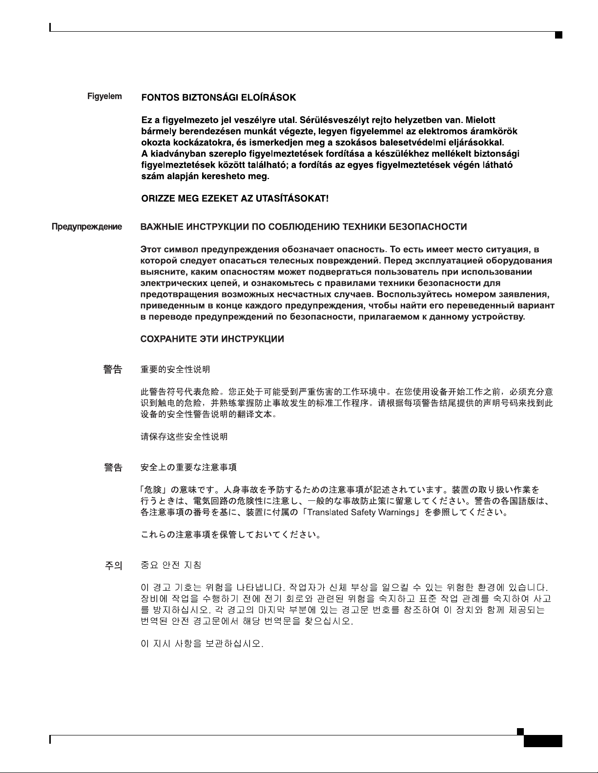
Safety warnings appear throughout this publication in procedures that, if performed incorrectly, can
cause physical injuries. A warning symbol precedes each warning statement.
Cisco Nexus 2000 Series Hardware Installation Guide
x
Page 11

Warning
Waarschuwing
Varoitus
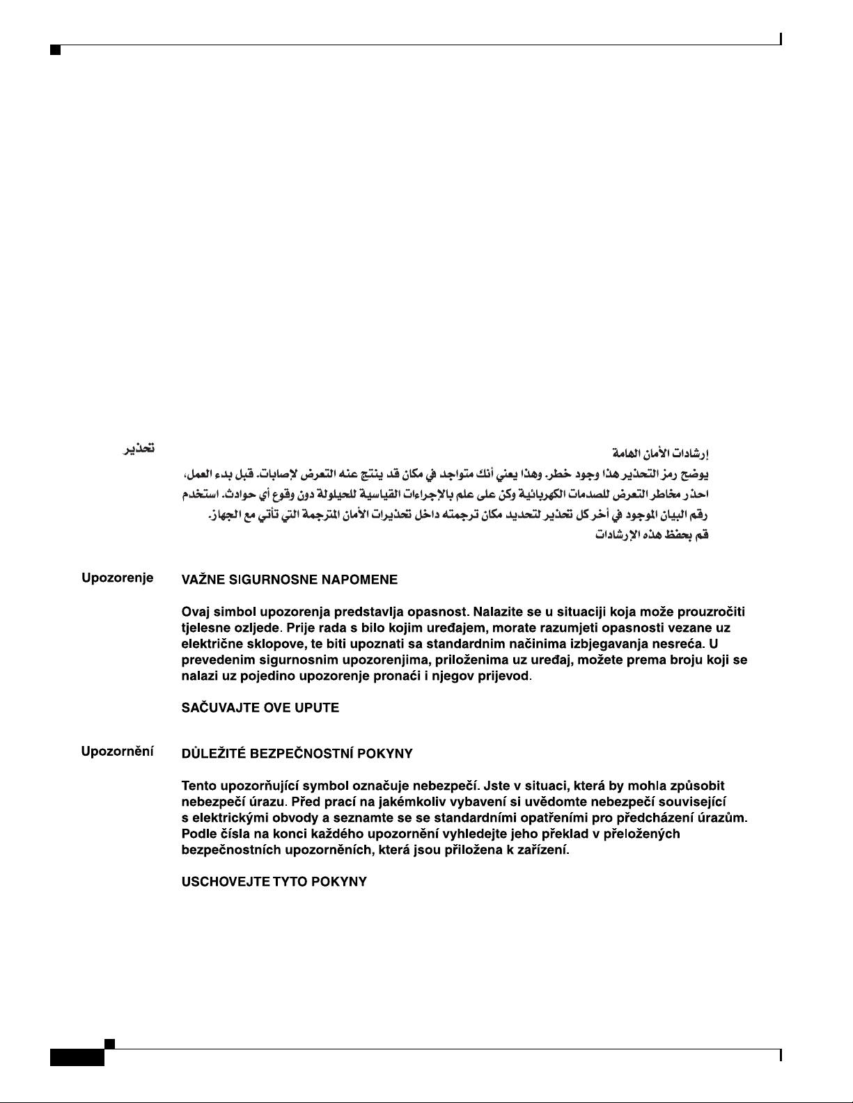
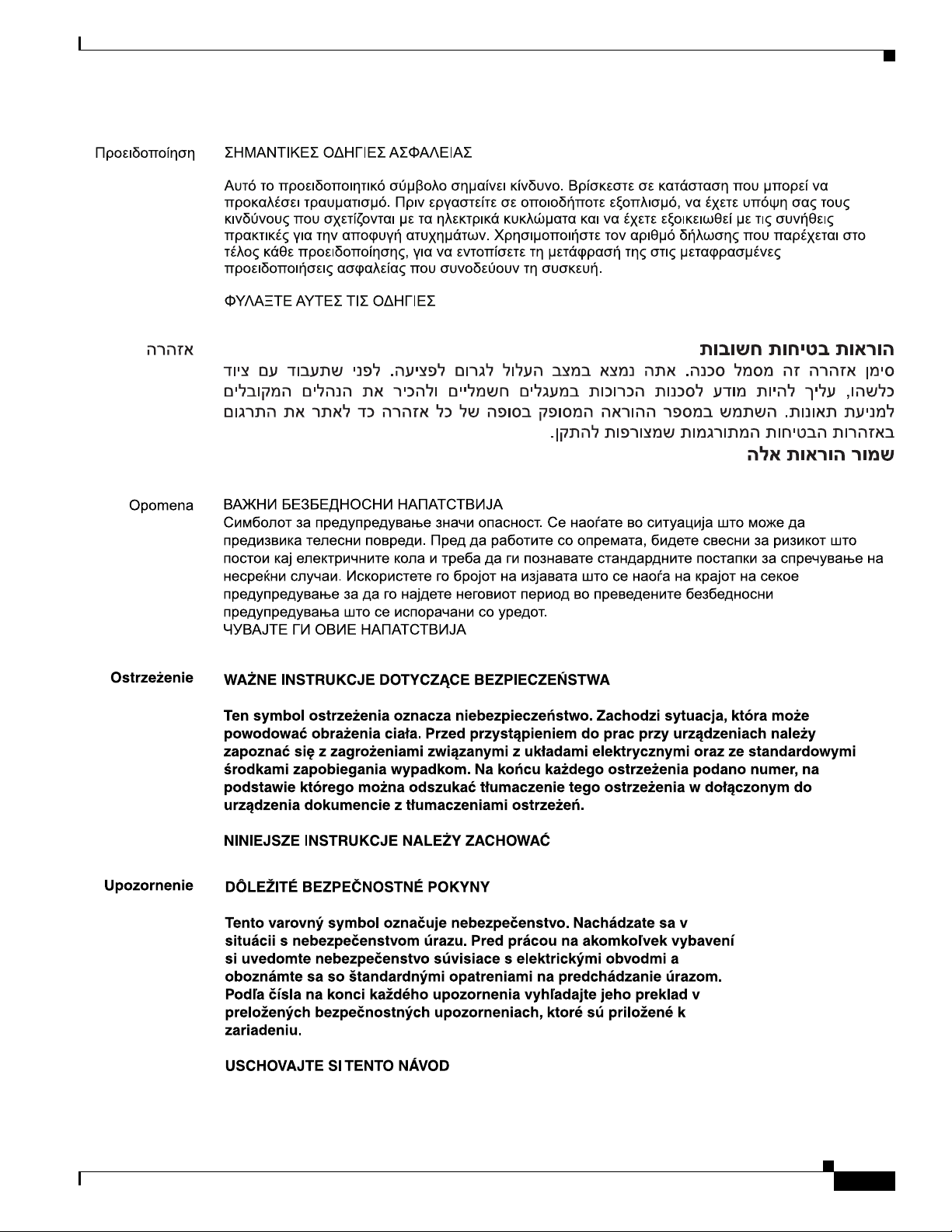
IMPORTANT SAFETY INSTRUCTIONS
This warning symbol means danger. You are in a situation that could cause bodily injury. Before you
work on any equipment, be aware of the hazards involved with electrical circuitry and be familiar
with standard practices for preventing accidents. Use the statement number provided at the end of
each warning to locate its translation in the translated safety warnings that accompanied this
device.
Statement 1071
SAVE THESE INSTRUCTIONS
BELANGRIJKE VEILIGHEIDSINSTRUCTIES
Dit waarschuwingssymbool betekent gevaar. U verkeert in een situatie die lichamelijk letsel kan
veroorzaken. Voordat u aan enige apparatuur gaat werken, dient u zich bewust te zijn van de bij
elektrische schakelingen betrokken risico's en dient u op de hoogte te zijn van de standaard
praktijken om ongelukken te voorkomen. Gebruik het nummer van de verklaring onderaan de
waarschuwing als u een vertaling van de waarschuwing die bij het apparaat wordt geleverd, wilt
raadplegen.
BEWAAR DEZE INSTRUCTIES
TÄRKEITÄ TURVALLISUUSOHJEITA
Tämä varoitusmerkki merkitsee vaaraa. Tilanne voi aiheuttaa ruumiillisia vammoja. Ennen kuin
käsittelet laitteistoa, huomioi sähköpiirien käsittelemiseen liittyvät riskit ja tutustu
onnettomuuksien yleisiin ehkäisytapoihin. Turvallisuusvaroitusten käännökset löytyvät laitteen
mukana toimitettujen käännettyjen turvallisuusvaroitusten joukosta varoitusten lopussa näkyvien
lausuntonumeroiden avulla.
Attention
Warnung
SÄILYTÄ NÄMÄ OHJEET
IMPORTANTES INFORMATIONS DE SÉCURITÉ
Ce symbole d'avertissement indique un danger. Vous vous trouvez dans une situation pouvant
entraîner des blessures ou des dommages corporels. Avant de travailler sur un équipement, soyez
conscient des dangers liés aux circuits électriques et familiarisez-vous avec les procédures
couramment utilisées pour éviter les accidents. Pour prendre connaissance des traductions des
avertissements figurant dans les consignes de sécurité traduites qui accompagnent cet appareil,
référez-vous au numéro de l'instruction situé à la fin de chaque avertissement.
CONSERVEZ CES INFORMATIONS
WICHTIGE SICHERHEITSHINWEISE
Dieses Warnsymbol bedeutet Gefahr. Sie befinden sich in einer Situation, die zu Verletzungen führen
kann. Machen Sie sich vor der Arbeit mit Geräten mit den Gefahren elektrischer Schaltungen und
den üblichen Verfahren zur Vorbeugung vor Unfällen vertraut. Suchen Sie mit der am Ende jeder
Warnung angegebenen Anweisungsnummer nach der jeweiligen Übersetzung in den übersetzten
Sicherheitshinweisen, die zusammen mit diesem Gerät ausgeliefert wurden.
BEWAHREN SIE DIESE HINWEISE GUT AUF.
Cisco Nexus 2000 Series Hardware Installation Guide
xi
Page 12

Avvertenza
Advarsel
Aviso
IMPORTANTI ISTRUZIONI SULLA SICUREZZA
Questo simbolo di avvertenza indica un pericolo. La situazione potrebbe causare infortuni alle
persone. Prima di intervenire su qualsiasi apparecchiatura, occorre essere al corrente dei pericoli
relativi ai circuiti elettrici e conoscere le procedure standard per la prevenzione di incidenti.
Utilizzare il numero di istruzione presente alla fine di ciascuna avvertenza per individuare le
traduzioni delle avvertenze riportate in questo documento.
CONSERVARE QUESTE ISTRUZIONI
VIKTIGE SIKKERHETSINSTRUKSJONER
Dette advarselssymbolet betyr fare. Du er i en situasjon som kan føre til skade på person. Før du
begynner å arbeide med noe av utstyret, må du være oppmerksom på farene forbundet med
elektriske kretser, og kjenne til standardprosedyrer for å forhindre ulykker. Bruk nummeret i slutten
av hver advarsel for å finne oversettelsen i de oversatte sikkerhetsadvarslene som fulgte med denne
enheten.
TA VARE PÅ DISSE INSTRUKSJONENE
INSTRUÇÕES IMPORTANTES DE SEGURANÇA
Este símbolo de aviso significa perigo. Você está em uma situação que poderá ser causadora de
lesões corporais. Antes de iniciar a utilização de qualquer equipamento, tenha conhecimento dos
perigos envolvidos no manuseio de circuitos elétricos e familiarize-se com as práticas habituais de
prevenção de acidentes. Utilize o número da instrução fornecido ao final de cada aviso para
localizar sua tradução nos avisos de segurança traduzidos que acompanham este dispositivo.
¡Advertencia!
Varning!
GUARDE ESTAS INSTRUÇÕES
INSTRUCCIONES IMPORTANTES DE SEGURIDAD
Este símbolo de aviso indica peligro. Existe riesgo para su integridad física. Antes de manipular
cualquier equipo, considere los riesgos de la corriente eléctrica y familiarícese con los
procedimientos estándar de prevención de accidentes. Al final de cada advertencia encontrará el
número que le ayudará a encontrar el texto traducido en el apartado de traducciones que acompaña
a este dispositivo.
GUARDE ESTAS INSTRUCCIONES
VIKTIGA SÄKERHETSANVISNINGAR
Denna varningssignal signalerar fara. Du befinner dig i en situation som kan leda till personskada.
Innan du utför arbete på någon utrustning måste du vara medveten om farorna med elkretsar och
känna till vanliga förfaranden för att förebygga olyckor. Använd det nummer som finns i slutet av
varje varning för att hitta dess översättning i de översatta säkerhetsvarningar som medföljer denna
anordning.
SPARA DESSA ANVISNINGAR
xii
Cisco Nexus 2000 Series Hardware Installation Guide
Page 13
Cisco Nexus 2000 Series Hardware Installation Guide
xiii
Page 14
Aviso
Advarsel
INSTRUÇÕES IMPORTANTES DE SEGURANÇA
Este símbolo de aviso significa perigo. Você se encontra em uma situação em que há risco de lesões
corporais. Antes de trabalhar com qualquer equipamento, esteja ciente dos riscos que envolvem os
circuitos elétricos e familiarize-se com as práticas padrão de prevenção de acidentes. Use o
número da declaração fornecido ao final de cada aviso para localizar sua tradução nos avisos de
segurança traduzidos que acompanham o dispositivo.
GUARDE ESTAS INSTRUÇÕES
VIGTIGE SIKKERHEDSANVISNINGER
Dette advarselssymbol betyder fare. Du befinder dig i en situation med risiko for
legemesbeskadigelse. Før du begynder arbejde på udstyr, skal du være opmærksom på de
involverede risici, der er ved elektriske kredsløb, og du skal sætte dig ind i standardprocedurer til
undgåelse af ulykker. Brug erklæringsnummeret efter hver advarsel for at finde oversættelsen i de
oversatte advarsler, der fulgte med denne enhed.
GEM DISSE ANVISNINGER
xiv
Cisco Nexus 2000 Series Hardware Installation Guide
Page 15
Cisco Nexus 2000 Series Hardware Installation Guide
xv
Page 16
Related Documentation
Documentation for Cisco Nexus 2000 Series Fabric Extenders is available at the following URL:
http://www.cisco.com/c/en/us/support/switches/nexus-2000-series-fabric-extenders/tsd-products-suppo
rt-series-home.html
The following are related Cisco Nexus 2000 Series Fabric Extender documents.
Release Notes
Cisco Nexus 5000 Series and Cisco Nexus 2000 Series Release Notes
Cisco Nexus 5000 Series Switch Release Notes
Configuration Guides
Cisco Nexus 5000 Series Configuration Limits for Cisco NX-OS Release 5.0(2)N1(1)
Cisco Nexus 5000 Series Configuration Limits for Cisco NX-OS Release 4.2(1)N1(1) and Release
4.2(1)N2(1)
Cisco Nexus 5000 Series NX-OS Fibre Channel over Ethernet Configuration Guide
Cisco Nexus 5000 Series NX-OS Layer 2 Switching Configuration Guide
Cisco Nexus 5000 Series NX-OS Multicast Routing Configuration Guide
Cisco Nexus 5000 Series NX-OS Quality of Service Configuration Guide
Cisco Nexus 5000 Series NX-OS SAN Switching Configuration Guide
xvi
Cisco Nexus 5000 Series NX-OS Security Configuration Guide
Cisco Nexus 5000 Series NX-OS System Management Configuration Guide
Cisco Nexus 5000 Series NX-OS Unicast Routing Configuration Guide
Cisco Nexus 5000 Series Switch NX-OS Software Configuration Guide
Cisco Nexus 5000 Series Fabric Manager Configuration Guide, Release 3.4(1a)
Cisco Nexus 7000 Series NX-OS Fundamentals Configuration Guide, Release 4.2
Cisco Nexus 2000 Series Hardware Installation Guide
Page 17

Cisco Nexus 2000 Series Fabric Extender Software Configuration Guide
Maintain and Operate Guides
Cisco Nexus 5000 Series NX-OS Operations Guide
Installation and Upgrade Guides
Cisco Nexus 5000 Series and Cisco Nexus 5500 Platform Hardware Installation Guide
Cisco Nexus 2000 Series Hardware Installation Guide
Cisco Nexus 5000 Series NX-OS Software Upgrade and Downgrade Guide, Release 4.2(1)N1(1)
Regulatory Compliance and Safety Information for the Cisco Nexus 5000 Series Switches and Cisco
Nexus 2000 Series Fabric Extenders
Licensing Guide
Cisco NX-OS Licensing Guide
Command References
Cisco Nexus 5000 Series Command Reference
Technical References
Cisco Nexus 5000 Series and Cisco Nexus 2000 Series Fabric Extender MIBs Reference
Error and System Messages
Cisco NX-OS System Messages Reference
Troubleshooting Guide
Cisco Nexus 5000 Troubleshooting Guide
Obtaining Documentation and Submitting a Service Request
For information on obtaining documentation, submitting a service request, and gathering additional
information, see the monthly What’s New in Cisco Product Documentation, which also lists all new and
revised Cisco technical documentation, at:
http://www.cisco.com/c/en/us/td/docs/general/whatsnew/whatsnew.html
Subscribe to the What’s New in Cisco Product Documentation as a Really Simple Syndication (RSS) feed
and set content to be delivered directly to your desktop using a reader application. The RSS feeds are a free
service and Cisco currently supports RSS Version 2.0.
Cisco Nexus 2000 Series Hardware Installation Guide
xvii
Page 18

xviii
Cisco Nexus 2000 Series Hardware Installation Guide
Page 19

CHA P T ER
1
Using a Fabric Extender with a Cisco Nexus 5000 Series or Cisco Nexus 6000 Series Switch
This chapter describes the Cisco Nexus Fabric Extenders (FEXs) and includes these sections:
• Information About Using a Fabric Extender with a Cisco Nexus Switch, page 1-1
• Cisco Nexus 2300 Series, page 1-1
• Cisco Nexus 2248TP-E, page 1-10
• Cisco Nexus 2248TP, page 1-17
• Cisco Nexus 2248PQ, page 1-24
• Cisco Nexus 2232TM-10GE, Cisco Nexus N2K-C2232TM-E-10GE, page 1-27
• Cisco Nexus 2224TP, page 1-32
• Cisco Nexus 2148T, page 1-36
Information About Using a Fabric Extender with a Cisco Nexus Switch
The Cisco Nexus Fabric Extenders (FEXs) support Gigabit Ethernet and 10-Gigabit Ethernet
environments while allowing transparent migration to 10-Gigabit Ethernet virtual machine aware unified
fabric technologies. The Cisco Nexus FEXs behave as remote I/O modules for a parent Cisco Nexus
switch. The FEX is an extension of the parent Cisco Nexus switch fabric, with the FEX and the parent
Cisco Nexus switch together forming a virtual modular system.
A Cisco Nexus FEX forwards all the traffic to the parent Cisco Nexus Switch over 10-Gigabit Ethernet
uplinks. Passing all traffic to the parent switch allows traffic to be shaped according to policies
established on the parent Cisco Nexus switch with a single point of management.
Cisco Nexus 2300 Series
The Cisco Nexus 2300 Series FEXs are stackable, hardware capable, 1 RU FEXs that support 48 1/10G
host ports as well as up to 6 40G uplink ports towards the parent switch. The 40G uplinks support bi-di
optics for seamlessly connectivity. The platform has a deep 32MB shared buffer for increased
performance.
Cisco Nexus 2000 Series Hardware Installation Guide
1-1
Page 20

Cisco Nexus 2300 Series
The Cisco Nexus 2348TQ provides 48 1/10GBASE-T host ports, while the Cisco Nexus 2348UPQ
provides 48 1/10G host unified ports. The unified ports provide native Fibre Channel as well as 1/10G
Ethernet and FCoE connectivity options.
You can order the platform with port side exhaust or port side intake air cooling. The port side exhaust
cooling model is compatible with data center hot-aisle and cold-aisle designs. This orientation places the
ports on the hot aisle aligned with the server ports. Port side intake airflow is used in network rack
designs in the data center such that the ports face the cold aisle. The Cisco Nexus 2300 Series is built for
non-stop operation, with redundant hot-swappable power supplies and redundant hot-swappable fans.
The Cisco Nexus 2300 Series platform is managed and configured by the upstream switch. The FEX
software ships with the Cisco Nexus switch software. The FEX downloads the software image from the
switch the same way that a module would download it from the supervisor in a modular chassis.
Note For the most current list of supported features, refer to the latest Cisco Nexus 2000 Series Fabric
Extenders Release Notes at every release.
This section includes the following topics:
Chapter 1 Using a Fabric Extender with a Cisco Nexus 5000 Series or Cisco Nexus 6000 Series Switch
• Chassis, page 1-2
• Ports, page 1-5
• Power Supplies, page 1-6
Chassis
• Fans, page 1-9
• Supported Transceivers and Cables, page 1-10
The Cisco Nexus 2300 Series platform has a one-rack-unit (1 RU) form factor that takes up relatively
little space, making it easy to incorporate into rack designs. The FEX is mounted in a standard 19-inch
(48.26 cm) rack. All switch ports at the rear of the unit are in close proximity to server ports, and all
user-serviceable components are accessible from the fan side panel.
You can order it with port side exhaust or port side intake air cooling, and with AC or DC power supplies.
The port side intake cooling model is intended for installations or deployments where the ports are in
the cold aisle, and the fans and power supplies are in the warm aisle.
Figure 1-1 and Figure 1-2 show the fan side view of the Cisco Nexus 2300 Series chassis. Figure 1-3 and
Figure 1-4 show the port side view of the Cisco Nexus 2348TQ chassis, and Figure 1-5 and Figure 1-6
show the port side view of the Cisco Nexus 2348UPQ chassis.
1-2
Cisco Nexus 2000 Series Hardware Installation Guide
Page 21
Chapter 1 Using a Fabric Extender with a Cisco Nexus 5000 Series or Cisco Nexus 6000 Series Switch
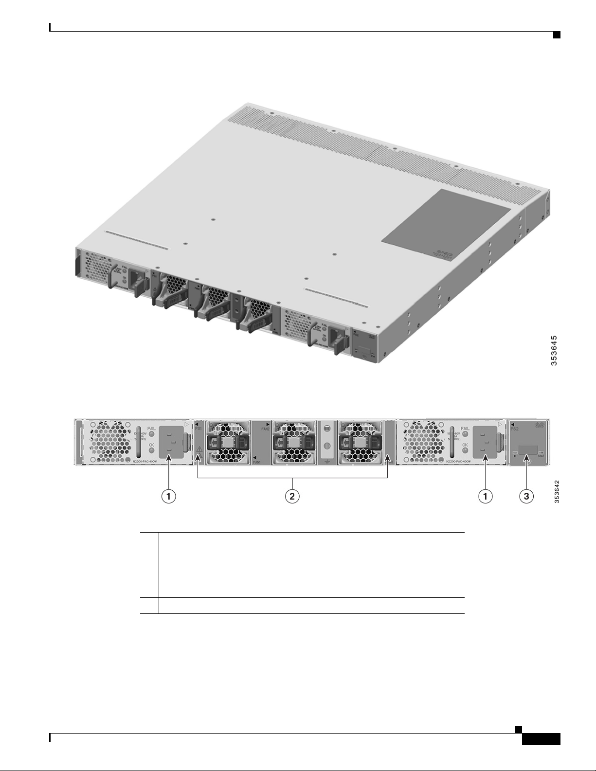
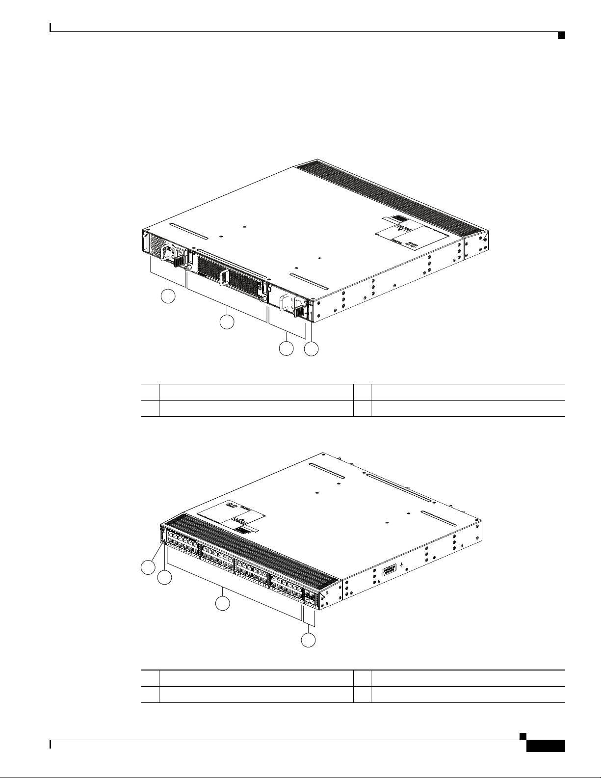
Figure 1-1 Fan Side View of the Cisco Nexus 2300 Series Chassis
Cisco Nexus 2300 Series
Figure 1-2 Close up of Fan Side View of the Cisco Nexus 2300 Series Chassis
1 Power supply
(two 1+1 redundant, hot-swappable power supplies)
2 Fans
(three, hot-swappable independent fans with support for 2+1 redundancy
3 Mgmt/Console port
Cisco Nexus 2000 Series Hardware Installation Guide
1-3
Page 22
Cisco Nexus 2300 Series
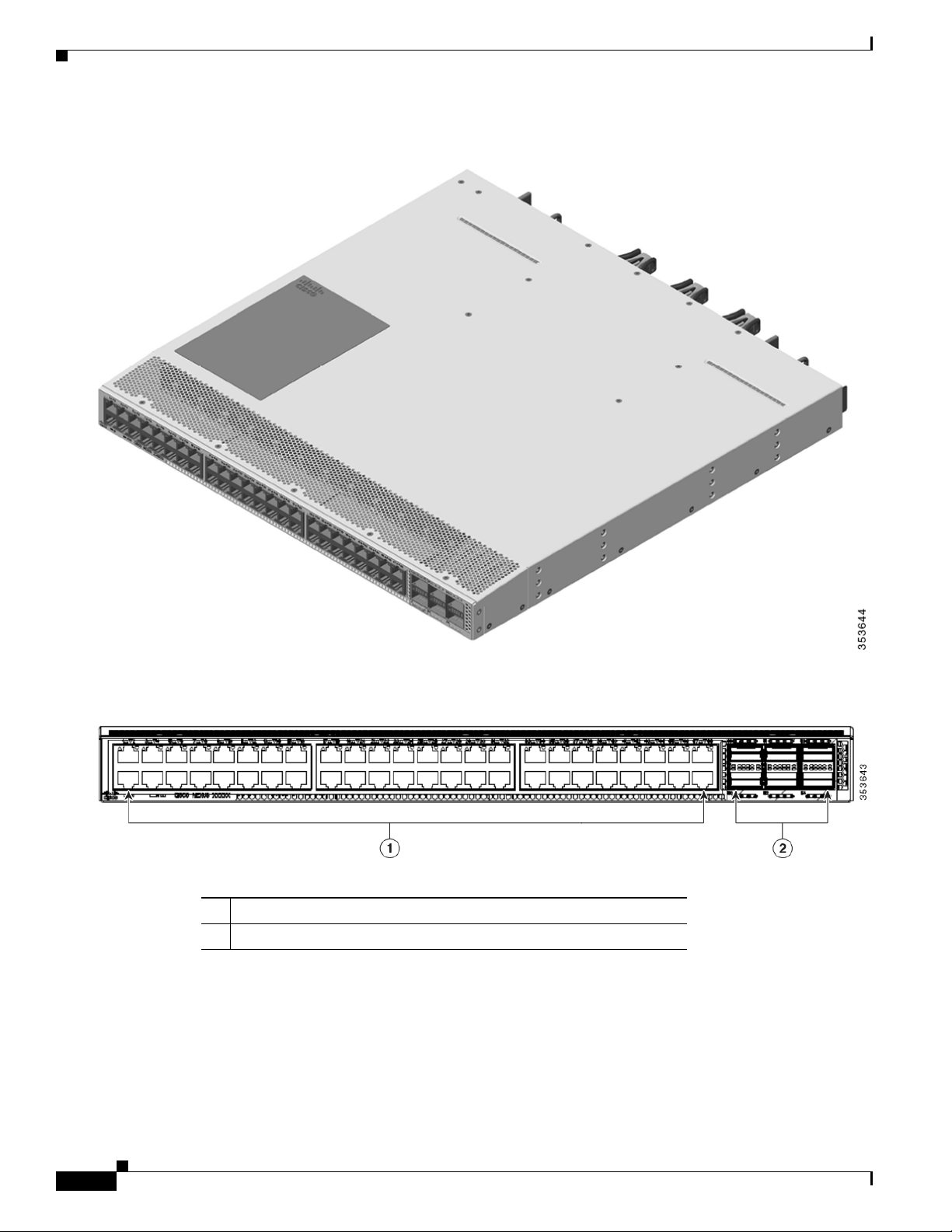
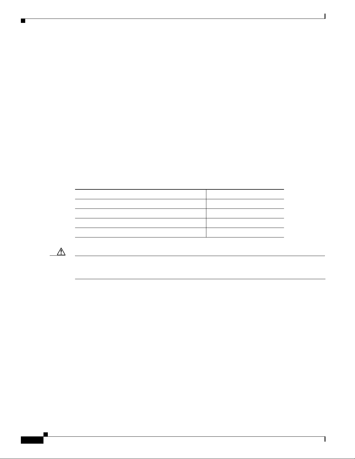
Figure 1-3 Port Side View of the Cisco Nexus 2348TQ Chassis
Chapter 1 Using a Fabric Extender with a Cisco Nexus 5000 Series or Cisco Nexus 6000 Series Switch
Figure 1-4 Close up of Port Side View of the Cisco Nexus 2348TQ Chassis
1 48 Fixed 1/10GBASE-T SFP+ Ports
2 6 40G QSFP+ Ports
Figure 1-1 shows the fan side view of the Cisco Nexus 2348UPQ chassis, and Figure 1-3 shows the port
side view of the chassis.
1-4
Cisco Nexus 2000 Series Hardware Installation Guide
Page 23
Chapter 1 Using a Fabric Extender with a Cisco Nexus 5000 Series or Cisco Nexus 6000 Series Switch
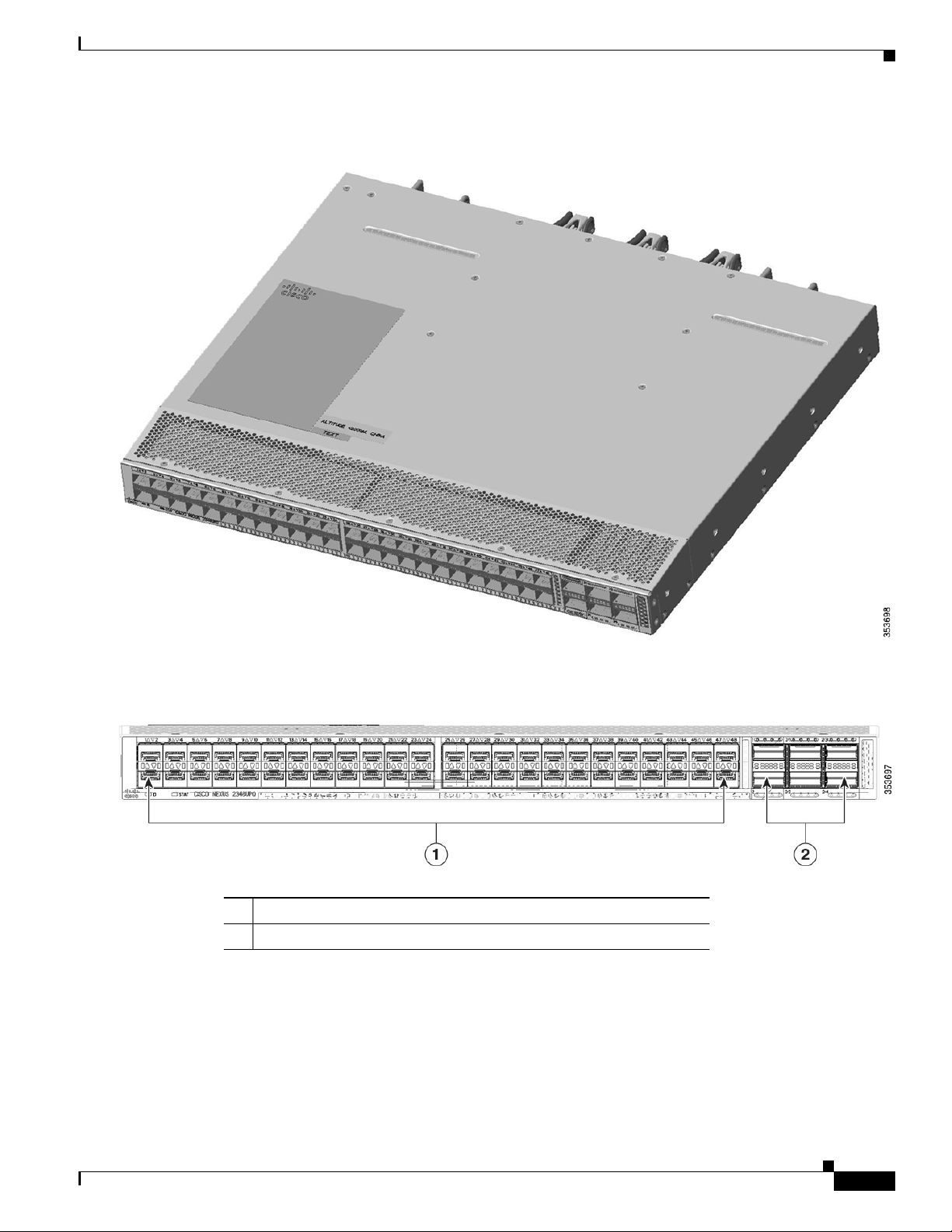
Figure 1-5 Port Side View of the Cisco Nexus 2348UPQ Chassis
Cisco Nexus 2300 Series
Ports
Figure 1-6 Close up of Port Side View of the Cisco Nexus 2348UPQ Chassis
1 48 Fixed 1/10G SFP+ Unified Capable Ports
2 6 40G QSFP+ Ports
The Cisco Nexus 2300 Series platform provides host-facing downlink ports, network-facing uplink
ports, and service interface ports. The Cisco Nexus 2300 Series platform supports 48 1/10G host ports
as well as up to 6 40G uplink ports towards the parent switch.
Cisco Nexus 2000 Series Hardware Installation Guide
1-5
Page 24
Cisco Nexus 2300 Series
On the Cisco Nexus 2348TQ, the host ports provide connectivity to 1/10GBASE-T Ethernet. Dedicated
uplink ports are color coded yellow (Network Interface Ports). Service Interface ports are color coded
white.
On the Cisco Nexus 2348UPQ the host unified ports provide connectivity to 1/10G Ethernet and FCoE.
Host ports with UP functionality are color coded orange (Host Interface Ports). Dedicated uplink ports
are color coded yellow (Network Interface Ports). Service Interface ports are color coded white.
Power Supplies
The Cisco Nexus 2300 Series platform has two 1+1 redundant power supplies. The chassis is fully
functional with one power supply, but you can install a second power supply for power redundancy. The
power supply is hot swappable during operations. Table 1-1 lists the power supplies that you can order
with the Cisco Nexus 2300 Series platform.
Table 1-1 Power Supplies for the Cisco Nexus 2300 Platform Chassis
Power Supply Part Number
AC power supply with port side exhaust airflow (Blue) N2200-PAC-400W
AC power supply with port side intake airflow (Red) N2200-PAC-400W-B
DC power supply with port side exhaust airflow (Blue) N2200-PDC-400W
DC power supply with port side intake airflow (Red) N2200-PDC-350W-B (for
Chapter 1 Using a Fabric Extender with a Cisco Nexus 5000 Series or Cisco Nexus 6000 Series Switch
Cisco Nexus 2348UPQ only)
Figure 1-7 shows an AC power supply with port-side exhaust airflow. Figure 1-8 shows an AC power
supply with port-side intake airflow. Figure 1-9 shows a DC power supply with port-side exhaust airflow.
Figure 1-10 shows a DC power supply with port-side intake airflow.
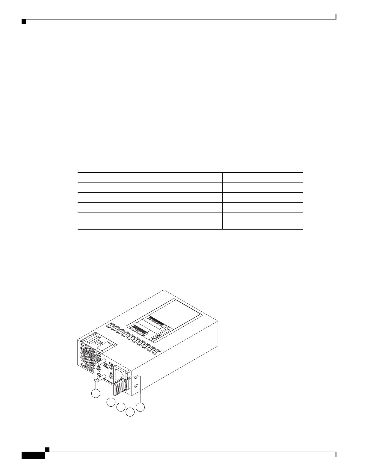
Figure 1-7 AC Power Supply with Port-Side Exhaust Airflow for the Cisco Nexus 2300 Platform
Chassis
1
2
3
5
4
239843
1-6
Cisco Nexus 2000 Series Hardware Installation Guide
Page 25
Chapter 1 Using a Fabric Extender with a Cisco Nexus 5000 Series or Cisco Nexus 6000 Series Switch
1
3
4
5
A220 P C-400
2
1
2
4
3
5
1 Handle 4 No black stripe (port side exhaust airflow)
2 FAIL (top) and OK (bottom) LEDs 5 AC power receptacle
3 Ejector latch
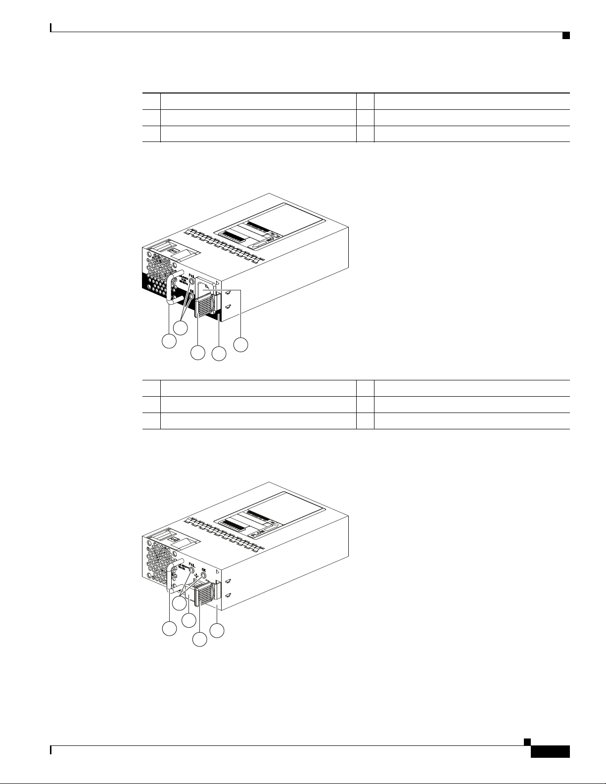
Figure 1-8 AC Power Supply with Port-Side Intake Airflow for the Cisco Nexus 2300 Platform
Chassis
Cisco Nexus 2300 Series
1 Handle 4 Black stripe (port side intake airflow)
2 FAIL (top) and OK (bottom) LEDs 5 AC power receptacle
3 Ejector latch
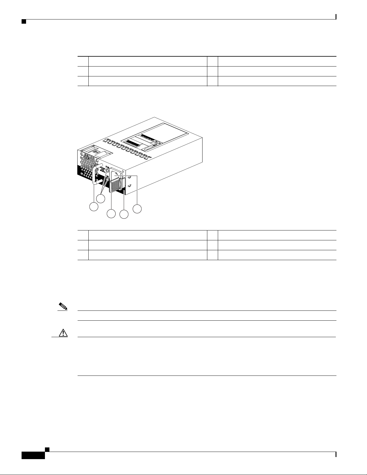
Figure 1-9 DC Power Supply with Port-Side Exhaust Airflow for the Cisco Nexus 2300 Platform
Chassis
Cisco Nexus 2000 Series Hardware Installation Guide
1-7
Page 26
Cisco Nexus 2300 Series
1
3
4
5
A220 P C-400
2
Figure 1-10 DC Power Supply with Port-Side Intake Airflow for the Cisco Nexus 2300 Platform
Chapter 1 Using a Fabric Extender with a Cisco Nexus 5000 Series or Cisco Nexus 6000 Series Switch
1 Handle 4 Ejector latch
2 FAIL (left) and OK (right) LEDs 5 No black stripe (port side exhaust airflow)
3 DC power receptacle
Chassis
1 Handle 4 Black stripe (port side intake airflow)
2 FAIL (top) and OK (bottom) LEDs 5 AC power receptacle
3 Ejector latch
You can order the Cisco Nexus 2300 Series platform with AC power supplies that have port-side exhaust
or port-side intake airflow for cooling or DC power supplies that offer port-side exhaust and port-side
intake airflow. The port-side intake airflow components have a black stripe on their front surface for easy
visual identification. The port-side exhaust airflow components do not have a black stripe.
Note Colored handles on each power supply clearly indicate the airflow direction.
Caution Be sure that all of the power supply and fan modules in the same chassis have the same airflow direction
and that the air intake for those modules is positioned on a cool aisle. If you install a module that uses a
different direction of airflow than the other modules in the same switch, the switch can overheat and shut
down. If you position a chassis with its modules taking cooling air from a warm aisle, the switch can
over heat and shut down.
If one power supply is installed in the chassis, but the other power supply slot is empty, you should use
a blank filler panel (part number N2200-P-BLNK) to cover the empty slot. Figure 1-11 shows a blank
power supply filler panel.
Cisco Nexus 2000 Series Hardware Installation Guide
1-8
Page 27
Chapter 1 Using a Fabric Extender with a Cisco Nexus 5000 Series or Cisco Nexus 6000 Series Switch
2
1
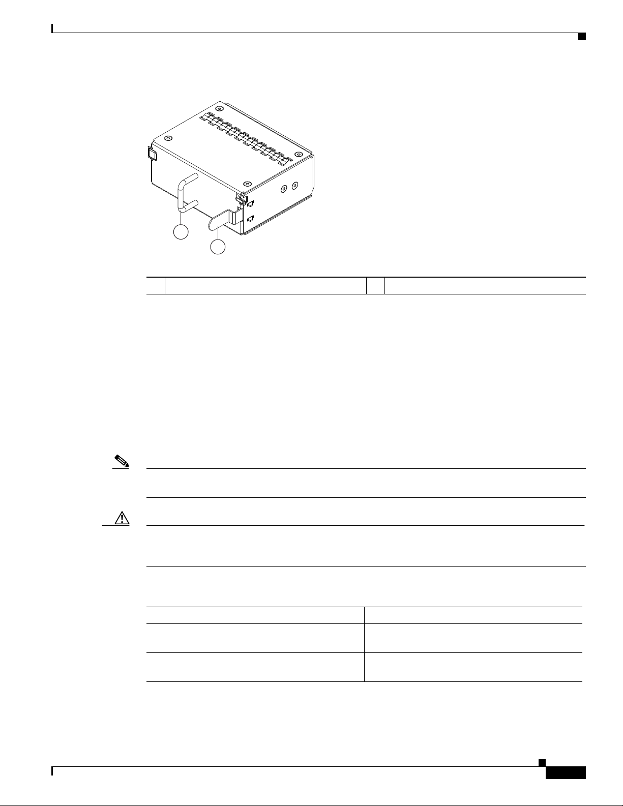
Figure 1-11 Blank Power Supply Filler Panel for the Cisco Nexus 2300 Platform Chassis
1 Handle 2 Ejector latch
For power supply specifications, see the “Power Specifications” section on page B-1. To replace a power
supply, see the “Removing and Installing Power Supplies” section on page 4-16.
Cisco Nexus 2300 Series
Fans
The Cisco Nexus 2300 Series platform has three, hot-swappable independent fans with support for 2+1
redundancy. Depending on the arrangement of hot and cold aisles in your data center, you can order
port-side exhaust airflow to position the fan side of the FEX chassis in a cold aisle or port-side intake
airflow to position the back of the FEX chassis in a cold aisle. Tab le 1-2 lists the part numbers for each
of the fans that you can use with the Cisco Nexus 2300 Series chassis.
Note Blue color coded tabs indicate port-side exhaust airflow. Red color coded tabs indicate port-side intake
airflow.
Caution Always make sure that all of the fan and power supply modules have the same direction of airflow and
the same color designation for that airflow direction. The switch does not support having more than one
direction of airflow with its modules.
Table 1-2 Fans for the Cisco Nexus 2300 Series Chassis
Description Part Number
Port side exhaust airflow N2K-2348UPQ-FAN (2348UPQ)
N2K-2348TQ-FAN (2348TQ)
Port side intake airflow N2K-2348UPQ-FAN-B (2348UPQ)
N2K-2348TQ-FAN-B (2348TQ)
To replace a fan, see the “Removing and Installing a Fan” section on page 4-19.
Cisco Nexus 2000 Series Hardware Installation Guide
1-9
Page 28

Chapter 1 Using a Fabric Extender with a Cisco Nexus 5000 Series or Cisco Nexus 6000 Series Switch
Cisco Nexus 2248TP-E
Supported Transceivers and Cables
The Cisco Nexus 2300 Series platform supports a wide variety of 1, 10, and 40 Gigabit Ethernet
connectivity options.
Caution Currently, passive copper cables are not supported on the NIF/SIF ports. Also, 100M FX optics are not
supported.
For the most current list of supported transceivers and optics, refer to the latest Cisco Nexus 2000 Series
Fabric Extenders Release Notes at every release.
Cisco Nexus 2248TP-E
The Cisco Nexus 2248TP-E is a stackable 1 RU 17.2-inch (45 cm) deep FEX that supports 48 1000-TX
host-facing (downlink) ports and 4 10-Gigabit SFP+ network-facing (uplink) ports. You can order it with
port side exhaust or port side intake air cooling, and with AC or DC power supplies.
Chassis
You can use this FEX with the Cisco Nexus 5000 Series switch. The Cisco Nexus 2248TP-E is managed
and configured by the upstream switch. The FEX software ships with the Cisco Nexus 5000 Series
switch software. The FEX downloads the software image from the switch the same way that a module
would download it from the supervisor in a modular chassis.
This section includes the following topics:
• Chassis, page 1-10
• Ports, page 1-12
• Power Supplies, page 1-12
• Fan Trays, page 1-15
• Supported Transceivers and Cables, page 1-17
The Cisco Nexus 2248TP-E FEX chassis has a height of 1.72 inches (4.37 cm), a width of 17.3 inches
(43.94 cm), and a depth of 17.7 inches (44.96 cm). It weighs 17.7 pounds (8.0 kg). Its one-rack-unit (1
RU) form factor takes up relatively little space, making it easy to incorporate into rack designs. The FEX
is mounted in a standard 19-inch (48.26 cm) rack. All switch ports at the rear of the unit are in close
proximity to server ports, and all user-serviceable components are accessible from the fan side.
You can order it with port-side exhaust or port-side intake air cooling, and with AC or DC power
supplies. If you are going to install the chassis with its fan side facing the cold aisle, you must order the
chassis with port-side exhaust air flow. If you are going to install the chassis with its back end facing the
cold aisle, you must order the chassis with port-side intake airflow.
1-10
Caution Always make sure that all of the fan tray and power supply modules have the same direction of airflow
and the same color designation for that airflow direction. The switch does not support having more than
one direction of airflow with its modules.
Cisco Nexus 2000 Series Hardware Installation Guide
Page 29
Chapter 1 Using a Fabric Extender with a Cisco Nexus 5000 Series or Cisco Nexus 6000 Series Switch
3
2
4
1
239287
Figure 1-12 shows the location of the components found on the fan side of the chassis, and Figure 1-13
shows the location of components found on the rear of the chassis. For information on what the chassis
and component LEDs indicate, see Table E-1 on page E-2.
Figure 1-12 Fan side view of the Cisco Nexus 2248TP-E Chassis
1
Cisco Nexus 2248TP-E
2
3
4
239288
1 Power supply 3 Power supply (blank shown)
2 Fan tray 4 Status (top) and ID (bottom) LEDs
Figure 1-13 Rear View of the Cisco Nexus 2248TP-E Chassis
1 Status (top) and ID (bottom) LEDs 3 100/1000 downlink ports (48)
2 HDMI port 4 SFP+ uplink ports (four)
Cisco Nexus 2000 Series Hardware Installation Guide
1-11
Page 30
Cisco Nexus 2248TP-E
Ports
The Cisco Nexus 2248TP-E FEX supports a total of 48 100/1000BASE-T ports and four 10-Gigabit
Ethernet uplinks (SFP+). The Cisco Nexus 2300 series provides three types of ports: ports for end-host
attachment (host interfaces), uplink ports (fabric interfaces) and flexible ports (to be configured as either
host or fabric interfaces). Fabric interfaces are for connectivity to the upstream parent Cisco Nexus
switch and are indicated by yellow color. Flexible interfaces can be used for connectivity to the upstream
parent or towards the host, and are indicated by white color.
Power Supplies
The Cisco Nexus 2248TP-E FEX chassis has two bays for fan side AC or DC power supplies. This
chassis is fully functional with one power supply, but you can install a second power supply for power
redundancy. The power supply is hot swappable during operations.
Table 1- 3 lists the power supplies that you can order with the Cisco Nexus 2248TP-E FEX.
Table 1-3 Power Supplies for the Cisco Nexus 2200 and Cisco Nexus 2300 Platform Chassis
Chapter 1 Using a Fabric Extender with a Cisco Nexus 5000 Series or Cisco Nexus 6000 Series Switch
Power Supply Part Number
AC power supply with port-side exhaust airflow N2200-PAC-400W
AC power supply with port-side intake airflow N2200-PAC-400W-B
DC power supply with port-side exhaust airflow N2200-PDC-400W
DC power supply with port-side intake airflow N2200-PDC-350W-B
Caution Always make sure that all of the fan tray and power supply modules have the same direction of airflow
and the same color designation for that airflow direction. The switch does not support having more than
one direction of airflow with its modules.
Figure 1-14 shows an AC power supply with port-side exhaust airflow. Figure 1-15 shows an AC power
supply with port-side intake airflow. Figure 1-16 shows a DC power supply with port-side exhaust
airflow. Figure 1-17 shows a DC power supply with port-side intake airflow.
1-12
Cisco Nexus 2000 Series Hardware Installation Guide
Page 31

Chapter 1 Using a Fabric Extender with a Cisco Nexus 5000 Series or Cisco Nexus 6000 Series Switch
1
3
4
5
A220 P C-400
2
Figure 1-14 AC Power Supply with Port-Side exhaust Airflow for the Cisco Nexus 2200 and Cisco
Nexus 2300 Platform Chassis
1
2
3
5
4
239843
Cisco Nexus 2248TP-E
1 Handle 4 No black stripe (port-side exhaust airflow)
2 FAIL (top) and OK (bottom) LEDs 5 AC power receptacle
3 Ejector latch
Figure 1-15 AC Power Supply with Port-Side Intake Airflow for the Cisco Nexus 2200 and Cisco
Nexus 2300 Platform Chassis
1 Handle 4 Black stripe (port side intake airflow)
2 FAIL (top) and OK (bottom) LEDs 5 AC power receptacle
3 Ejector latch
Cisco Nexus 2000 Series Hardware Installation Guide
1-13
Page 32

Cisco Nexus 2248TP-E
1
2
4
3
5
1
3
4
5
239932
A220 P C-400
2
Chapter 1 Using a Fabric Extender with a Cisco Nexus 5000 Series or Cisco Nexus 6000 Series Switch
Figure 1-16 DC Power Supply with Port-Side Exhaust Airflow for the Cisco Nexus 2200 and Cisco
Nexus 2300 Platform Chassis
1 Handle 4 Ejector latch
2 FAIL (left) and OK (right) LEDs 5 No black stripe (port-side exhaust airflow)
3 DC power receptacle
Figure 1-17 DC Power Supply with Port-Side Intake Airflow for the Cisco Nexus 2200 and Cisco
Nexus 2300 Platform Chassis
1 Handle 4 Black stripe (port-side intake airflow)
2 FAIL (top) and OK (bottom) LEDs 5 AC power receptacle
3 Ejector latch
1-14
Cisco Nexus 2000 Series Hardware Installation Guide
Page 33

Chapter 1 Using a Fabric Extender with a Cisco Nexus 5000 Series or Cisco Nexus 6000 Series Switch
2
1
You can order the Cisco Nexus 2248TP-E FEX with AC power supplies that have port side exhaust or
port side intake airflow for cooling or DC power supplies that offer port side exhaust airflow. The port
side intake airflow components have a black stripe on their fan side surface for easy visual identification.
The port side exhaust airflow components do not have a black stripe.
Caution Be sure that all of the power supply and fan tray modules in the same chassis have the same airflow
direction and that the air intake for those modules is positioned on a cool aisle. If you install a module
that uses a different direction of airflow from the other modules in your system, you will see an error
message. If you position a chassis with its modules taking cooling air from a warm aisle, the switch can
over heat and shut down.
If one power supply is installed in the chassis, but the other power supply slot is empty, you should use
a blank filler panel (part number N2200-P-BLNK) to cover the empty slot. Figure 1-18 shows a blank
power supply filler panel.
Figure 1-18 Blank Power Supply Filler Panel for the Cisco Nexus 2200 and Cisco Nexus 2300
Platform Chassis
Cisco Nexus 2248TP-E
Fan Trays
1 Handle 2 Ejector latch
For power supply specifications, see the “Power Specifications” section on page B-1. To replace a power
supply, see the “Removing and Installing Power Supplies” section on page 4-16. For LED descriptions,
see Table E-1 on page E-2.
The Cisco Nexus 2248TP-E FEX has one fan tray that is hot swappable during operations. Depending
on the arrangement of hot and cold aisles in your data center, you can order port-side exhaust airflow to
position the fan side of the FEX chassis in a cold aisle or port-side intake airflow to position the back of
the FEX chassis in a cold aisle. Ta ble 1-4 lists the part numbers for each of the fan trays that you can use
with the Cisco Nexus 2248TP-E chassis.
Cisco Nexus 2000 Series Hardware Installation Guide
1-15
Page 34

Cisco Nexus 2248TP-E
3
2
1
1
Caution Always make sure that all of the fan tray and power supply modules have the same direction of airflow
Chapter 1 Using a Fabric Extender with a Cisco Nexus 5000 Series or Cisco Nexus 6000 Series Switch
Table 1-4 Fan Trays for the Cisco Nexus 2248TP-E FEXs
Description Part Number
port-side exhaust airflow N2K-C2248TP-FAN
port-side intake airflow N2K-C2248TP-FAN-B
and the same color designation for that airflow direction. The switch does not support having more than
one direction of airflow with its modules.
Figure 1-19 shows a port-side exhaust airflow fan tray, and Figure 1-20 shows a port-side intake airflow
fan tray.
Figure 1-19 Port-Side Exhaust Airflow Fan Tray Components for the Cisco Nexus 2248TP-E and
2224TP FEXs
1 Captive screws (2) 3 Status LED
2 No black stripe indicates port-side exhaust
airflow
Cisco Nexus 2000 Series Hardware Installation Guide
1-16
Page 35

Chapter 1 Using a Fabric Extender with a Cisco Nexus 5000 Series or Cisco Nexus 6000 Series Switch
Figure 1-20 Port-Side Intake Airflow Fan Tray for the Cisco Nexus 2248TP-E FEX
1
2
3
1
Cisco Nexus 2248TP
239934
1 Captive screws (2) 3 Status LED
2 Black stripe indicates port-side intake airflow
To replace a fan tray, see the “Removing and Installing the Fan Tray” section on page 4-21. For LED
descriptions, see Table E-1 on page E-2.
Supported Transceivers and Cables
The Cisco Nexus 2248TP-E FEX supports SFP+ Ethernet transceivers. The enhanced
Small-Form-Factor Pluggable (SFP+) 10-Gigabit Ethernet transceiver is a bidirectional device with a
transmitter and receiver. It has a 20-pin connector on the electrical interface and duplex LC connector
on the optical interface. Currently, the Cisco Nexus 2248TP-E FEX supports the short-range SFP and
long-range SFP transceiver. Copper interface cables are available for use with the 10-Gigabit Ethernet
SFP+ transceiver. For details see, the Cisco Nexus 2000 Series Fabric Extenders Release Notes.
Cisco Nexus 2248TP
The Cisco Nexus 2248TP is a stackable 1 RU 17.2-inch (45 cm) deep FEX that supports 48 1000-TX
host-facing (downlink) ports and 4 10-Gigabit SFP+ network-facing (uplink) ports. You can order it with
port side exhaust or port side intake air cooling, and with AC or DC power supplies.
You can use this FEX with the Cisco Nexus 5000 Series switch. The Cisco Nexus 2248TP is managed
and configured by the upstream switch. The FEX software ships with the Cisco Nexus 5000 Series
switch software. The FEX downloads the software image from the switch the same way that a module
would download it from the supervisor in a modular chassis.
This section includes the following topics:
• Chassis, page 1-18
• Ports, page 1-19
Cisco Nexus 2000 Series Hardware Installation Guide
1-17
Page 36

Cisco Nexus 2248TP
Chassis
Chapter 1 Using a Fabric Extender with a Cisco Nexus 5000 Series or Cisco Nexus 6000 Series Switch
• Power Supplies, page 1-19
• Fan Tray, page 1-22
• Supported Transceivers and Cables, page 1-24
The Cisco Nexus 2248TP FEX chassis has a height of 1.72 inches (4.37 cm), a width of 17.3 inches
(43.94 cm), and a depth of 17.7 inches (44.96 cm). It weighs 17.7 pounds (8.0 kg). Its one-rack-unit (1
RU) form factor takes up relatively little space, making it easy to incorporate into rack designs. The FEX
is mounted in a standard 19-inch (48.26 cm) rack. All switch ports at the rear of the unit are in close
proximity to server ports, and all user-serviceable components are accessible from the fan side.
You can order it with port-side exhaust or port-side intake air cooling (do not mix air directions for a
chassis), and with AC or DC power supplies. If you are going to install the chassis with its fan side facing
the cold aisle, you must order the chassis with port-side exhaust airflow. If you are going to install the
chassis with its back end facing the cold aisle, you must order the chassis with port-side intake airflow.
Figure 1-21 shows the location of the components found on the fan side of the chassis, and Figure 1-22
shows the location of components found on the rear of the chassis. For information on what the chassis
and component LEDs indicate, see Table E-1 on page E-2.
Figure 1-21 Fan side view of the Cisco Nexus 2248TP Chassis
1
2
3
4
239288
1 Power supply 3 Power supply (blank shown)
2 Fan tray 4 Status (top) and ID (bottom) LEDs
1-18
Cisco Nexus 2000 Series Hardware Installation Guide
Page 37

Chapter 1 Using a Fabric Extender with a Cisco Nexus 5000 Series or Cisco Nexus 6000 Series Switch
3
2
4
1
Figure 1-22 Rear View of the Cisco Nexus 2248TP Chassis
Cisco Nexus 2248TP
1 Status (top) and ID (bottom) LEDs 3 100/1000 downlink ports (48)
2 HDMI port 4 SFP+ uplink ports (four)
Ports
The Cisco Nexus 2248TP FEX supports a total of 48 100/1000BASE-T ports and four, 10-Gigabit
Ethernet uplinks (SFP+). It provides two types of ports: host-facing downlink ports and network-facing
uplink ports. Uplink ports are differentiated with yellow for connectivity to the upstream parent Cisco
Nexus 5000 Series switch.
Power Supplies
The Cisco Nexus 2248TP FEX chassis has two bays for fan side AC or DC power supplies. This chassis
is fully functional with one power supply, but you can install a second power supply for power
redundancy. The power supply is hot swappable during operations.
Table 1- 5 lists the power supplies that you can order with the Cisco Nexus 2248TP FEX.
Table 1-5 Power Supplies for the Cisco Nexus 2200 and Cisco Nexus 2300 Platform Chassis
Power Supply Part Number
AC power supply with port-side exhaust airflow N2200-PAC-400W
AC power supply with port-side intake airflow N2200-PAC-400W-B
DC power supply with port-side exhaust airflow N2200-PDC-400W
DC power supply with port-side intake airflow N2200-PDC-350W-B
Cisco Nexus 2000 Series Hardware Installation Guide
1-19
Page 38

Cisco Nexus 2248TP
Caution Always make sure that all of the fan tray and power supply modules have the same direction of airflow
Chapter 1 Using a Fabric Extender with a Cisco Nexus 5000 Series or Cisco Nexus 6000 Series Switch
and the same color designation for that airflow direction. The switch does not support having more than
one direction of airflow with its modules.
Figure 1-23 shows an AC power supply with port-side exhaust airflow. Figure 1-24 shows an AC power
supply with port-side intake airflow. Figure 1-25 shows a DC power supply with port-side exhaust
airflow.
Figure 1-23 AC Power Supply with Port-Side Exhaust Airflow for the Cisco Nexus 2200 and Cisco
Nexus 2300 Platform Chassis
1
2
3
5
4
239843
1 Handle 4 No black stripe (port-side exhaust airflow)
2 OK (top) and FAULT (bottom) LEDs 5 AC power receptacle
3 Ejector latch
1-20
Cisco Nexus 2000 Series Hardware Installation Guide
Page 39

Chapter 1 Using a Fabric Extender with a Cisco Nexus 5000 Series or Cisco Nexus 6000 Series Switch
1
3
4
5
A220 P C-400
2
1
2
4
3
5
Figure 1-24 AC Power Supply with Port-Side Intake Airflow for the Cisco Nexus 2200 and Cisco
Nexus 2300 Platform Chassis
Cisco Nexus 2248TP
1 Handle 4 Black stripe (port-side intake airflow)
2 FAULT (top) and OK (bottom) LEDs 5 AC power receptacle
3 Ejector latch
Figure 1-25 DC Power Supply with Port-Side Exhaust Airflow for the Cisco Nexus 2200 and Cisco
Nexus 2300 Platform Chassis
1 Handle 4 Ejector latch
2 FAULT (top) and OK (bottom) LEDs 5 No black stripe (port-side exhaust airflow)
3 DC power receptacle
Cisco Nexus 2000 Series Hardware Installation Guide
1-21
Page 40

Cisco Nexus 2248TP
2
1
Caution Be sure that all of the power supply and fan tray modules in the same chassis have the same airflow
Chapter 1 Using a Fabric Extender with a Cisco Nexus 5000 Series or Cisco Nexus 6000 Series Switch
You can order the Cisco Nexus 2248TP FEX with AC power supplies that have port-side exhaust or
port-side intake airflow for cooling or DC power supplies that offer port-side exhaust airflow. The
port-side intake airflow components have a black stripe on their fan side surface for easy visual
identification. The port-side exhaust airflow components do not have a black stripe.
direction and that the air intake for those modules is positioned on a cool aisle. If you install a module
that uses a different direction of airflow from the other modules in your system, you will see an error
message. If you position a chassis with its modules taking cooling air from a warm aisle, the switch can
over heat and shut down.
If one power supply is installed in the chassis, but the other power supply slot is empty, you should use
a blank filler panel (part number N2200-P-BLNK) to cover the empty slot. Figure 1-26 shows a blank
power supply filler panel.
Figure 1-26 Blank Power Supply Filler Panel for the Cisco Nexus 2200 and Cisco Nexus 2300
Platform Chassis
Fan Tray
1-22
1 Handle 2 Ejector latch
For power supply specifications, see the “Power Specifications” section on page B-1. To replace a power
supply, see the “Removing and Installing Power Supplies” section on page 4-16. For LED descriptions,
see Table E-1 on page E-2.
The Cisco Nexus 2248TP (and 2224TP) FEX has one fan tray that is hot swappable during operations.
Depending on the arrangement of hot and cold aisles in your data center, you can order port-side exhaust
airflow to position the fan side of the FEX chassis in a cold aisle or port-side intake airflow to position
the back of the FEX chassis in a cold aisle. Ta ble 1-6 lists the part numbers for each of the fan trays that
you can use with the Cisco Nexus 2248TP and 2224TP chassis.
Cisco Nexus 2000 Series Hardware Installation Guide
Page 41

Chapter 1 Using a Fabric Extender with a Cisco Nexus 5000 Series or Cisco Nexus 6000 Series Switch
3
2
1
1
Table 1-6 Fan Trays for the Cisco Nexus 2248TP and 2224TP FEXs
Description Part Number
Port-side exhaust airflow N2K-C2248-FAN
Port-side intake airflow N2K-C2248-FAN-B
Caution Always make sure that all of the fan tray and power supply modules have the same direction of airflow
and the same color designation for that airflow direction. The switch does not support having more than
one direction of airflow with its modules.
Figure 1-27 shows a port-side exhaust airflow fan tray, and Figure 1-28 shows a port side intake airflow
fan tray.
Figure 1-27 Port-Side Exhaust Airflow Fan Tray Components for the Cisco Nexus 2248TP and
2224TP FEXs
Cisco Nexus 2248TP
1 Captive screws (2) 3 Status LED
2 No black stripe indicates port-side exhaust
airflow
Cisco Nexus 2000 Series Hardware Installation Guide
1-23
Page 42

Cisco Nexus 2248PQ
Chapter 1 Using a Fabric Extender with a Cisco Nexus 5000 Series or Cisco Nexus 6000 Series Switch
Figure 1-28 Port-Side Intake Airflow Fan Tray for the Cisco Nexus 2248TP and 2224TP FEXs
1
2
3
1
239934
1 Captive screws (2) 3 Status LED
2 Black stripe indicates port-side intake airflow
To replace a fan tray, see the “Removing and Installing the Fan Tray” section on page 4-21. For LED
descriptions, see Table E-1 on page E-2.
Supported Transceivers and Cables
The Cisco Nexus 2248TP FEX supports SFP+ Ethernet transceivers. The enhanced Small-Form-Factor
Pluggable (SFP+) 10-Gigabit Ethernet transceiver is a bidirectional device with a transmitter and
receiver. It has a 20-pin connector on the electrical interface and duplex LC connector on the optical
interface. Currently, the Cisco Nexus 2000 Series FEX supports the short-range SFP and long-range SFP
transceiver. Copper interface cables are available for use with the 10-Gigabit Ethernet SFP+ transceiver.
For an updated list of supported transceivers and optics, please see the Cisco Nexus 2000 Series Fabric
Extenders Release Notes.
Cisco Nexus 2248PQ
The Cisco Nexus 2248PQ is a stackable 1 RU 17.2 inch (45 cm) deep FEX that supports high-density
10-Gigabit Ethernet environments and has 48 1/10-Gigabit SFP+ host interfaces and 4 QSFP+ (16
10-Gigabit) on network interfaces. QSFP+ connectivity simplifies cabling while lowering power and
solution costs. You can order it with port side exhaust or port side intake air cooling, which makes this
FEX compatible with hot-aisle, cold aisle data center designs.
1-24
You can use this FEX with the Cisco Nexus 5500 Series switch and the Cisco Nexus 6004 parent switch
(The supported software is Cisco Nexus OS Release 6.0(2)N1(1)). The Cisco Nexus 2248PQ is managed
and configured by the upstream switch. The FEX software ships with the Cisco Nexus 5500 Series
switch software. The FEX downloads the software image from the switch the same way that a module
would download it from the supervisor in a modular chassis.
Cisco Nexus 2000 Series Hardware Installation Guide
Page 43

Chapter 1 Using a Fabric Extender with a Cisco Nexus 5000 Series or Cisco Nexus 6000 Series Switch
This section includes the following topics:
• Chassis, page 1-25
• Ports, page 1-25
• Power Supplies, page 1-25
• Fan Trays, page 1-26
• Supported SFP+ Transceivers, page 1-27
Chassis
The Cisco Nexus 2248PQ FEX chassis has a height of 1.72 inches (4.37 cm), a width of 17.3 inches
(43.94 cm), and a depth of 17.7 inches (44.96 cm). It weighs 17.5 pounds (8.0 kg). Its one-rack-unit (1
RU) form factor takes up relatively little space, making it easy to incorporate into rack designs. The FEX
is mounted in a standard 19-inch (48.26 cm) rack. All of the switch ports at the rear of the chassis are in
close proximity to server ports, and all user-serviceable components are accessible from the fan side.
You can order port-side exhaust airflow or port-side intake airflow for cooling. If you are going to install
the chassis with its fan side facing the cold aisle, you must order the chassis with port-side exhaust air
flow. If you are going to install the chassis with its back end facing the cold aisle, you must order the
chassis with port-side intake airflow.
Cisco Nexus 2248PQ
Ports
The Cisco Nexus 2248PQ FEX supports a total of 48 1/10-Gigabit Ethernet/Fibre Channel over Ethernet
(FCoE) ports (SFP+) and 4 QSFP+ (16 10-Gigabit) fabric ports. The Cisco Nexus 2248PQ provides two
types of ports: ports for end-host attachments and uplink ports. Uplink ports are differentiated with
yellow for connectivity to the upstream parent Cisco Nexus 5000 Series switch.
The Cisco Nexus 2248PQ 10GE Fabric Extender supports FCoE and Data Center Bridging (DCB) which
increases the reliability, efficiency, and scalability of Ethernet networks by allowing the switches to
support multiple traffic classes over a lossless Ethernet fabric, enabling consolidation of LAN, SAN, and
cluster environments.
Power Supplies
The Cisco Nexus 2248PQ FEX chassis has two bays for fan side AC or DC power supplies. This chassis
is fully functional with one power supply, but you can install a second power supply for power
redundancy. The power supply is hot swappable during operations.
Table 1- 7 lists the power supplies that you can order with the Cisco Nexus 2248PQ FEX.
Table 1-7 Power Supplies for the Cisco Nexus 2200 and Cisco Nexus 2300 Platform Chassis
Power Supply Part Number
AC power supply with port-side exhaust airflow N2200-PAC-400W
AC power supply with port-side intake airflow N2200-PAC-400W-B
Cisco Nexus 2000 Series Hardware Installation Guide
1-25
Page 44

Cisco Nexus 2248PQ
Caution Be sure that all of the power supply and fan tray modules in the same chassis have the same airflow
Chapter 1 Using a Fabric Extender with a Cisco Nexus 5000 Series or Cisco Nexus 6000 Series Switch
Table 1-7 Power Supplies for the Cisco Nexus 2200 and Cisco Nexus 2300 Platform Chassis
Power Supply Part Number
DC power supply with port-side exhaust airflow N2200-PDC-400W
DC power supply with port-side intake airflow N2200-PDC-350W-B
Figure 1-23 on page 1-20 shows an AC power supply with port-side exhaust airflow. Figure 1-24 on
page 1-21 shows an AC power supply with port-side intake airflow. Figure 1-25 on page 1-21 shows a
DC power supply with port-side exhaust airflow.
You can order the Cisco Nexus 2248PQ FEX with AC power supplies that have port-side exhaust or
port-side intake airflow for cooling or DC power supplies that have port-side exhaust airflow. The
port-side intake airflow components have a black stripe on their fan side surface for easy visual
identification. The port-side exhaust airflow components do not have a black stripe.
Table 1-5 on page 1-19 lists the power supplies that you can order with the Cisco Nexus 2200 and Cisco
Nexus 2300 Platform FEXs.
direction and that the air intake for those modules is positioned on a cool aisle. If you install a module
that uses a different direction of airflow from the other modules in your system, you will see an error
message. If you position a chassis with its modules taking cooling air from a warm aisle, the switch can
over heat and shut down.
Caution Hot swapping of different direction fans and power supplies is not supported.
Fan Trays
If one power supply is installed in the chassis, but the other power supply slot is empty, you should use
a blank filler panel (N2200-P-BLNK) to cover the empty slot. Figure 1-26 on page 1-22 shows a blank
power supply filler panel.
For power supply specifications, see “Power Specifications”. To replace a power supply, see the
“Removing and Installing Power Supplies” section on page 4-16.
The Cisco Nexus 2248PQ FEX has one fan tray that is hot swappable during operations. Depending on
whether there is a cold aisle in the fan side or port side of the chassis, you can order port side exhaust
airflow or port side intake airflow for the fan tray and the power supplies in the same chassis. Table 1-8
lists the part numbers for each of the fan trays that you can use with this chassis.
Table 1-8 Fan Trays for the Cisco Nexus 2248PQ FEX
Description Part Number
Port-side exhaust airflow (blue color coded fans) N2K-C2248PQ-FAN
Port-side intake airflow (red color coded fans) N2K-C2248PQ-FAN-B
1-26
Cisco Nexus 2000 Series Hardware Installation Guide
Page 45

Chapter 1 Using a Fabric Extender with a Cisco Nexus 5000 Series or Cisco Nexus 6000 Series Switch
Cisco Nexus 2232TM-10GE, Cisco Nexus N2K-C2232TM-E-10GE
Caution Always make sure that all of the fan tray and power supply modules have the same direction of airflow
and the same color designation for that airflow direction. The switch does not support having more than
one direction of airflow with its modules.
To replace a fan tray, see the “Removing and Installing the Fan Tray” section on page 4-21. For LED
descriptions, see “Chassis and Module LEDs for the Cisco Nexus Fabric Extenders”.
Supported SFP+ Transceivers
The Cisco Nexus 2248PQ Series FEX supports SFP+ Ethernet transceivers. The enhanced
Small-Form-Factor Pluggable (SFP+) 10-Gigabit Ethernet transceiver is a bidirectional device with a
transmitter and receiver. It has a 20-pin connector on the electrical interface and duplex LC connector
on the optical interface. Currently, the Cisco Nexus 2000 Series FEX supports the short-range SFP and
long-range SFP transceiver. Copper interface cables are available for use with the 10-Gigabit Ethernet
SFP+ transceiver. For an updated list of supported transceivers and optics, please see the Cisco Nexus
2000 Series Fabric Extenders Release Notes.
Cisco Nexus 2232TM-10GE, Cisco Nexus N2K-C2232TM-E-10GE
The Cisco Nexus 2232TM-10GE is a stackable 1 RU 17.72 inch (45 cm) deep FEX that supports 32
1/10-Gigabit Base-T host-facing (downlink) ports and 8 10-Gigabit Ethernet (SFP+) network-facing
(uplink) ports through an uplink module.
You can use this FEX with the Cisco Nexus 5000 Series switch. The Cisco Nexus 2232TM-10GE is
managed and configured by the upstream switch. The FEX software ships with the Cisco Nexus 5000
Series switch software. The FEX downloads the software image from the switch the same way that a
module would download it from the supervisor in a modular chassis.
You can use the Cisco Nexus 2232TM-E-10GE with the Cisco Nexus 5000 Series switch starting in the
NX-OS 5.2(1)N1(1) release and beyond
This section includes the following topics:
• Chassis, page 1-27
• Ports, page 1-29
• Power Supplies, page 1-30
• Fan Trays, page 1-31
• Supported Transceivers and Cables, page 1-32
Chassis
The Cisco Nexus 2232TM FEX chassis has a height of 1.72 inches (4.37 cm), a width of 17.3 inches
(43.94 cm), and a depth of 17.7 inches (44.96 cm). It weighs 18.5 pounds (8.4 kg). Its one-rack-unit (1
RU) form factor takes up relatively little space, making it easy to incorporate into rack designs. The FEX
is mounted in a standard 19-inch (48.26 cm) rack and supports vertical orientation. All of the switch
ports at the rear of the chassis are in close proximity to server ports, and all user-serviceable components
are accessible from the fan side.
Cisco Nexus 2000 Series Hardware Installation Guide
1-27
Page 46

Chapter 1 Using a Fabric Extender with a Cisco Nexus 5000 Series or Cisco Nexus 6000 Series Switch
1
2
3
4
330055
Cisco Nexus 2232TM-10GE, Cisco Nexus N2K-C2232TM-E-10GE
You can order it with port-side exhaust or port-side intake air cooling, and AC or DC power supplies. If
you are going to install the chassis with its fan side facing the cold aisle, you must order the chassis with
port-side exhaust airflow. If you are going to install the chassis with its back end facing the cold aisle,
you must order the chassis with port-side intake airflow.
Figure 1-29 shows the location of the components on the fan of the chassis, and Figure 1-30 shows the
location of components on the rear of the chassis. For information on what the chassis and component
LEDs indicate, see “Chassis and Module LEDs for the Cisco Nexus Fabric Extenders”.
Figure 1-29 Fan side view of the Cisco Nexus 2232TM-10GE Chassis
1 Power supply 3 Power supply
2 Fan tray 4 Status (top) and ID (bottom) LEDs
Cisco Nexus 2000 Series Hardware Installation Guide
1-28
Page 47

Chapter 1 Using a Fabric Extender with a Cisco Nexus 5000 Series or Cisco Nexus 6000 Series Switch
1
2
3
4
330056
Cisco Nexus 2232TM-10GE, Cisco Nexus N2K-C2232TM-E-10GE
Figure 1-30 Rear View of the Cisco Nexus 2232TM Chassis
1 Status and ID LEDs 3 10-Gigabit Base-T host-facing (downlink)
ports (32)
2 HDMI port 4 10-Gigabit SFP+ ports (8)
Ports
The Cisco Nexus 2232TM FEX supports a total of 32 10-Gigabit Ethernet ports (SFP+) and 8 10-Gigabit
Ethernet/FCoE uplinks (SFP+). SFP transceivers can also be plugged into the SFP+ cages to allow a
1-Gigabit downlink. The Cisco Nexus 2232TM-10GE provides two types of ports: ports for end-host
attachment and uplink ports. Uplink ports, which are colored yellow, connect to the upstream parent
Cisco Nexus 5000 Series switch.
The Cisco Nexus 2232TM-10GE supports Data Center Bridging (DCB) which increases the reliability,
efficiency, and scalability of Ethernet networks by allowing the switches to support multiple traffic
classes over a lossless Ethernet fabric. These features allow the switches to support multiple traffic
classes over a lossless Ethernet fabric, enabling consolidation of LAN, SAN, and cluster environments.
Figure 1-31 shows the ports on the rear of the Cisco Nexus 2232TM-10GE chassis.
Cisco Nexus 2000 Series Hardware Installation Guide
1-29
Page 48

Chapter 1 Using a Fabric Extender with a Cisco Nexus 5000 Series or Cisco Nexus 6000 Series Switch
3
330057
2
4
1
Cisco Nexus 2232TM-10GE, Cisco Nexus N2K-C2232TM-E-10GE
Figure 1-31 Ports Located on the Rear of the Cisco Nexus 2232TM-10GE Chassis
1 Status (top) and ID (bottom) LEDs 3 32 10-Gigabit BaseT host ports
2 HDMI Connector 4 8 10-Gigabit SFP+ ports
Power Supplies
The Cisco Nexus 2232TM-10GE FEX chassis has two bays for fan side AC or DC power supplies. This
chassis is fully functional with one power supply, but you can install a second power supply for power
redundancy. The power supply is hot-swappable during operations.
Table 1- 9 lists the power supplies that you can order with the Cisco Nexus 2232TM-10GE FEX.
Table 1-9 Power Supplies for the Cisco Nexus 2232TM-10GE FEX
Power Supply Part Number
AC power supply with port-side exhaust airflow N2K-PAC-400W
AC power supply with port-side intake airflow N2K-PAC-400W-B
DC power supply with port-side exhaust airflow N2K-PDC-400W
Figure 1-23 on page 1-20 shows an AC power supply with port-side exhaust airflow. Figure 1-24 on
page 1-21 shows an AC power supply with port-side intake airflow. Figure 1-25 on page 1-21 shows a
DC power supply with port-side exhaust airflow.
You can order the Cisco Nexus 2232TM-10GE FEX with AC power supplies that have port-side exhaust
or port-side intake airflow for cooling or DC power supplies that have port-side exhaust airflow. The
port-side intake airflow components have a black stripe on their fan side surface for easy visual
identification. The port-side exhaust airflow components do not have a black stripe.
Caution Be sure that all of the power supply and fan tray modules in the same chassis have the same airflow
direction and that the air intake for those modules is positioned on a cool aisle. If you install a module
that uses a different direction of airflow from the other modules in your system, you will see an error
message. If you position a chassis with its modules taking cooling air from a warm aisle, the switch can
over heat and shut down.
If one power supply is installed in the chassis, but the other power supply slot is empty, you should use
a blank filler panel (N2200-P-BLNK) to cover the empty slot. Figure 1-26 on page 1-22 shows a blank
power supply filler panel.
1-30
Cisco Nexus 2000 Series Hardware Installation Guide
Page 49

Chapter 1 Using a Fabric Extender with a Cisco Nexus 5000 Series or Cisco Nexus 6000 Series Switch
4
2
1
3
1
239292
Cisco Nexus 2232TM-10GE, Cisco Nexus N2K-C2232TM-E-10GE
For power supply specifications, see Power Specifications, page B-1. To replace a power supply, see the
“Removing and Installing Power Supplies” section on page 4-16.
For LED descriptions, see “Chassis and Module LEDs for the Cisco Nexus Fabric Extenders”.
Fan Trays
The Cisco Nexus 2232TM-10GE FEX has one fan tray that is hot swappable during operations.
Depending on whether there is a cold aisle in fan side or port side of the chassis, you can order port-side
exhaust airflow or port-side intake airflow for the fan tray and the power supplies in the same chassis.
Table 1- 10 lists the part numbers for each of the fan trays that you can use with this chassis.
Table 1-10 Fan Trays for the Cisco Nexus 2232TM-10GE FEX
Description Part Number
Port-side exhaust airflow N2K-C2232-FAN
Port-side intake airflow N2K-C2232-FAN-B
Caution Always make sure that all of the fan tray and power supply modules have the same direction of airflow
and the same color designation for that airflow direction. The switch does not support having more than
one direction of airflow with its modules.
To see the components used when installing a fan tray, see Figure 1-32 (port-side exhaust airflow) or
Figure 1-33 (port-side intake airflow).
Figure 1-32 Port-Side Exhaust Airflow Fan Tray for the Cisco Nexus 2232TM-10GE FEX
Cisco Nexus 2000 Series Hardware Installation Guide
1-31
Page 50

Cisco Nexus 2224TP
Chapter 1 Using a Fabric Extender with a Cisco Nexus 5000 Series or Cisco Nexus 6000 Series Switch
1 Captive screws (2) 3 No black stripe indicates port-side exhaust
airflow
2 Handle 4 Status LED
Figure 1-33 Port-Side Intake Airflow Fan Tray for the Cisco Nexus 2232TM-10GE FEX
1
2
3
1 Captive screws (2) 3 Status LED
2 Black stripe indicates port-side intake airflow
To replace a fan tray, see the “Removing and Installing the Fan Tray” section on page 4-21. For LED
descriptions, see Table E-1 on page E-2.
Supported Transceivers and Cables
The Cisco Nexus 2232TM-10GE Series FEX supports SFP+ Ethernet transceivers. The enhanced
Small-Form-Factor Pluggable (SFP+) 10-Gigabit Ethernet transceiver is a bidirectional device with a
transmitter and receiver. It has a 20-pin connector on the electrical interface and duplex LC connector
on the optical interface. Currently, the FEX supports the short-range SFP and long-range SFP
transceiver. Copper interface cables are available for use with the 10-Gigabit Ethernet SFP+ transceiver.
For an updated list of supported transceivers and optics, please see the Cisco Nexus 2000 Series Fabric
Extenders Release Notes.
1
239936
Cisco Nexus 2224TP
The Cisco Nexus 2224TP is a stackable 1 RU FEX. This FEX is very similar to the Cisco Nexus 2248TP
except that it has 24 100/1000BASE-T downlink ports, 2 SFP+ uplink ports and you can order it with
port-side exhaust airflow or port-side intake airflow. You can use this FEX with the Cisco Nexus 5000
Series switch. The Cisco Nexus 2224TP is managed and configured by the upstream switch. The FEX
Cisco Nexus 2000 Series Hardware Installation Guide
1-32
Page 51

Chapter 1 Using a Fabric Extender with a Cisco Nexus 5000 Series or Cisco Nexus 6000 Series Switch
2
1
3
4
239281
software ships with the Cisco Nexus 5000 Series switch software. The FEX downloads the software
image from the switch the same way that a module would download it from the supervisor in a modular
chassis.
This section includes the following topics:
• Chassis, page 1-33
• Ports, page 1-34
• Power Supplies, page 1-34
• Fan Tray, page 1-35
• Supported SFP+ Transceivers, page 1-36
Chassis
The Cisco Nexus 2224TP chassis has a height of 1.72 inches (4.37 cm), a width of 17.34 inches (44.04
cm), and a depth of 18.9 inches (48.1 cm). It weighs 18 pounds (8.0 kg). Its one-rack-unit (1 RU) form
factor takes up relatively little space, making it easy to incorporate into rack designs. The FEX is
mounted in a standard 19-inch (48.26-cm) rack. It has port side exhaust or port side intake airflow for
cooling. All switch ports are located at the rear of the unit in close proximity to server ports, and all
user-serviceable components are accessible from the fan side.
Figure 1-34 shows the location of the components on the fan side of the chassis, and Figure 1-35 shows
the location of components on the rear of the chassis. For information on what the chassis and component
LEDs indicate, see Table E-1 on page E-2.
Cisco Nexus 2224TP
Figure 1-34 Fan side of the Cisco Nexus 2224TP Chassis
1 Power supply 3 Power supply (blank power supply shown)
2 Fan tray (1) 4 Status (top) and ID (bottom) LEDs
Cisco Nexus 2000 Series Hardware Installation Guide
1-33
Page 52

Cisco Nexus 2224TP
Chapter 1 Using a Fabric Extender with a Cisco Nexus 5000 Series or Cisco Nexus 6000 Series Switch
Figure 1-35 Rear View of the Nexus 2224TP Chassis
1
2
3
1 Status (top) and ID (bottom) LEDs 3 100/1000BASE-T data ports (24)
2 HDMI port 4 SFP+ uplink ports (2)
Ports
The Cisco Nexus 2224TP FEX supports a total of 24 100/1000BASE-T downlink ports and two SFP+
uplink ports on the rear panel. There is an HDMI port on the rear panel for console and management port
connectivity. Uplink ports are colored yellow for connectivity to the upstream parent Cisco Nexus 5000
Series switch.
Power Supplies
The Cisco Nexus 2224TP FEX chassis has two bays for fan side AC or DC power supplies (the same
power supplies used for the Cisco Nexus 2248TP). This chassis is fully functional with one power
supply, but you can install a second power supply for power redundancy. The power supply is hot
swappable during operations.
Table 1- 11 lists the power supplies that you can order with the Cisco Nexus 2224TP FEX.
4
239280
1-34
Table 1-11 Power Supplies for the Cisco Nexus 2224TP FEX
Power Supply Part Number
AC power supply with port-side exhaust airflow N2200-PAC-400W
AC power supply with port-side intake airflow N2200-PAC-400W-B
DC power supply with port-side exhaust airflow N2200-PDC-400W
DC power supply with port-side intake airflow N2200-PDC-350W-B
Cisco Nexus 2000 Series Hardware Installation Guide
Page 53

Chapter 1 Using a Fabric Extender with a Cisco Nexus 5000 Series or Cisco Nexus 6000 Series Switch
To see the components that you use when installing a power supply unit, see Figure 1-23 on page 1-20
for the AC power supply with port-side exhaust airflow, Figure 1-24 on page 1-21 for the AC power
supply with port-side intake airflow, and Figure 1-25 on page 1-21 for the DC power supply with
port-side exhaust airflow.
You can order the Cisco Nexus 2224TP FEX with AC power supplies that have port-side exhaust or
port-side intake airflow for cooling or DC power supplies that have port-side exhaust airflow. The
port-side intake airflow components have a black stripe on their fan side surface for easy visual
identification. The port-side exhaust airflow components do not have a black stripe.
Caution Be sure that all of the power supply and fan tray modules in the same chassis have the same airflow
direction and that the air intake for those modules is positioned on a cool aisle. If you install a module
that uses a different direction of airflow from the other modules in your system, you will see an error
message. If you position a chassis with its modules taking cooling air from a warm aisle, the switch can
over heat and shut down.
If one power supply is installed in the chassis, but the other power supply slot is empty, you should use
a blank filler panel to cover the empty slot. Figure 1-26 on page 1-22 shows a blank power supply filler
panel.
For power supply specifications, see Table B-1 on page B-2. To replace a power supply, see the
“Removing and Installing Power Supplies” section on page 4-16.
Cisco Nexus 2224TP
Fan Tray
Caution Always make sure that all of the fan tray and power supply modules have the same direction of airflow
The Cisco Nexus 2224TP FEX has one fan tray that is hot swappable during operations. Depending on
whether there is a cold aisle in fan side or port-side of the chassis, you can order port-side exhaust airflow
or port-side intake airflow for the fan tray and the power supplies in the same chassis. Table 1-12 lists
the part numbers for each of the fan trays that you can use with this chassis.
Table 1-12 Fan Trays for the Cisco Nexus 2224TP and 2248TP FEXs
Description Part Number
port side exhaust airflow N2K-C2248-FAN
port side intake airflow N2K-C2248-FAN-B
and the same color designation for that airflow direction. The switch does not support having more than
one direction of airflow with its modules.
To see the components used when installing one of these fan trays, see Figure 1-27 (port side exhaust
airflow) or Figure 1-28 (port side intake airflow).
To replace a fan tray, see the “Removing and Installing the Fan Tray” section on page 4-21. For LED
descriptions, see Table E-1 on page E-2.
Cisco Nexus 2000 Series Hardware Installation Guide
1-35
Page 54

Chapter 1 Using a Fabric Extender with a Cisco Nexus 5000 Series or Cisco Nexus 6000 Series Switch
Cisco Nexus 2148T
Supported SFP+ Transceivers
The Cisco Nexus 2224TP FEX supports SFP+ Ethernet transceivers. The enhanced Small-Form-Factor
Pluggable (SFP+) 10-Gigabit Ethernet transceiver is a bidirectional device with a transmitter and
receiver. It has a 20-pin connector on the electrical interface and duplex LC connector on the optical
interface. Currently, the Cisco Nexus 2224TP FEX supports the short-range SFP and long-range SFP
transceiver. Copper interface cables are available for use with the 10-Gigabit Ethernet SFP+ transceiver.
For an updated list of supported transceivers and optics, please see the Cisco Nexus 2000 Series Fabric
Extenders Release Notes.
Cisco Nexus 2148T
The Cisco Nexus 2148T FEX is a 1 RU device that acts as a remote I/O module on the Cisco Nexus 5000
Series switch. All device configurations are managed on the switch and configuration information is
downloaded through inband communication to the FEX. You can use this FEX with the Cisco Nexus
5000 Series switch. The FEX software ships with the Cisco Nexus 5000 Series switch software. The FEX
downloads the software image from the switch the same way that a module would download it from the
supervisor in a modular chassis.
This section includes the following topics:
• Features, page 1-36
Features
Chassis
• Chassis, page 1-36
• Ports, page 1-38
• Power Supplies, page 1-38
• Fan Tray, page 1-39
• Supported SFP Transceivers, page 1-40
The Cisco Nexus 2148T FEX has the following features:
• Forty-eight 1-Gigabit Ethernet ports
• Four 10-Gigabit Ethernet ports
• Redundant (dual) 200-W modular, hot-swappable power supplies with a power switch on each
supply
• Removable fan tray with redundant fans. The fan tray can be removed for hot swapping. If it is not
replaced within 60 seconds, the system shuts down.
• Port-side exhaust airflow
1-36
The Cisco Nexus 2148T FEX has a height of 1.72 inches (4.37 cm), a width of 17.3 inches (43.94 cm),
and a depth of 20 inches (50.8 cm). The FEX is mounted in a standard 19-inch (48.24 cm) rack. The
chassis requires 1 RU. One fan tray and two power supplies are located at the fan side of the device. The
Cisco Nexus 2000 Series Hardware Installation Guide
Page 55

Chapter 1 Using a Fabric Extender with a Cisco Nexus 5000 Series or Cisco Nexus 6000 Series Switch
273914
1
1
2
3
273916
3
2
1
4
ports are located at the rear of the device. The chassis has port-side exhaust airflow with cool air entering
the chassis through the fan tray and power supply modules and exhausting through the port side of the
chassis.
Figure 1-36 identifies the features on the fan side of the Cisco Nexus 2148T FEX.
Figure 1-36 Fan side view of the Cisco Nexus 2148T FEX
Cisco Nexus 2148T
1 Power supply (two) 3 Status (top) and ID (bottom) LEDs
2 Fan tray (1)
The rear of the Cisco Nexus 2148T FEX has 48 1-Gigabit Ethernet ports, 4 10-Gigabit Ethernet ports,
and status and ID LEDs. Figure 1-37 identifies the components found on the rear of the Cisco Nexus
2148T FEX.
Figure 1-37 Rear View of the Cisco Nexus 2148T FEX
1 System status (top) and Beacon (bottom) LED 3 1-Gigabit Ethernet downlink ports (48)
2 HDMI port 4 10-Gigabit Ethernet uplink ports (4)
Cisco Nexus 2000 Series Hardware Installation Guide
1-37
Page 56

Cisco Nexus 2148T
239274
1
2
3
4
Ports
Chapter 1 Using a Fabric Extender with a Cisco Nexus 5000 Series or Cisco Nexus 6000 Series Switch
Each port on the Cisco Nexus 2148T FEX is numbered, and groups of ports are numbered based on their
function. The ports are numbered from top to bottom and left to right.
Group 1 includes 48 1-Gigabit Ethernet data ports. Group 2 includes four 10-Gigabit Ethernet ports.
Figure 1-38 shows how ports are numbered and grouped by function.
Figure 1-38 Port Numbering on the Cisco Nexus 2148T FEX
A B
1 Group 1: Data ports 1 through 48 2 Group 2: Uplink ports 1 through 4
Power Supplies
The Cisco Nexus 2148T FEX uses a fan side 200-W AC power supply that has port-side exhaust airflow.
The chassis has two bays for two power supplies. Two power supplies can be used for redundancy, but
the Cisco Nexus 2148T FEX is fully functional with one power supply. Figure 1-39 shows the power
supply with two LEDs: one for power status and one for a failure condition. The power supply is
hot-swappable. For details on how to install a power supply, see the “Removing and Installing Power
Supplies” section on page 4-16.
Figure 1-39 AC Power Supply for the Cisco Nexus 2148T Series FEX
1234567891011121314151617181920212223242526272829303132333435363738394041424344454647
123
48
4
192533
1 Green power LED indicates the power status. 2 Amber fail LED indicates a failure condition.
If one power supply is installed in the chassis, but the other power supply slot is empty, you should use
a blank filler panel to cover the empty slot. Figure 1-40 shows a blank power supply filler panel.
Cisco Nexus 2000 Series Hardware Installation Guide
1-38
Page 57

Chapter 1 Using a Fabric Extender with a Cisco Nexus 5000 Series or Cisco Nexus 6000 Series Switch
Figure 1-40 Blank Power Supply Filler Panel
1
2
1 Handle 2 Ejector latch
239290
Cisco Nexus 2148T
Fan Tray
The Cisco Nexus 2148T FEX has one fan tray that has port-side exhaust airflow. Figure 1-41 shows the
fan tray. The fan tray is hot-swappable as long as you replace it within 60 seconds.
Figure 1-41 Port-Side Exhaust Airflow Fan Tray for Cisco Nexus 2148T FEX
1
2
3
1
239291
Cisco Nexus 2000 Series Hardware Installation Guide
1-39
Page 58

Chapter 1 Using a Fabric Extender with a Cisco Nexus 5000 Series or Cisco Nexus 6000 Series Switch
Cisco Nexus 2148T
1 Captive screws (2) 2 Status LED
3 No black stripe indicates port-side exhaust
airflow
Supported SFP Transceivers
The Cisco Nexus 2148T FEX supports SFP+ Ethernet transceivers. The enhanced Small-Form-Factor
Pluggable (SFP+) 10-Gigabit Ethernet transceiver is a bidirectional device with a transmitter and
receiver. It has a 20-pin connector on the electrical interface and duplex LC connector on the optical
interface. Currently, the FEX supports the short-range SFP and long-range SFP transceiver. Copper
interface cables are available for use with the 10-Gigabit Ethernet SFP+ transceiver. For an updated list
of supported transceivers and optics, please see the Cisco Nexus 2000 Series Fabric Extenders Release
Notes.
1-40
Cisco Nexus 2000 Series Hardware Installation Guide
Page 59

CHA P T ER
2
Using a Fabric Extender with a Cisco Nexus 7000 Series Switch
This chapter describes the Cisco Nexus 2200 Platform Fabric Extender (FEX) chassis and the
components that you can connect to a Cisco Nexus 7000 Series switch. This chapter includes the
following sections:
• Information About Using a Fabric Extender with a Cisco Nexus 7000 Series Switch, page 2-1
• Cisco Nexus 2248TP-E FEX, page 2-2
• Cisco Nexus 2248TP FEX, page 2-11
• Cisco Nexus 2232TM FEX, page 2-15
• Cisco Nexus 2232PP FEX, page 2-22
• Cisco Nexus 2224TP FEX, page 2-27
Information About Using a Fabric Extender with a Cisco Nexus 7000 Series Switch
You can extend the Cisco Nexus 7000 Series switch architecture by connecting up to 32 FEXs as remote
I/O modules. Depending on which FEX model that you connect to the switch, the FEX provides
top-of-the-rack connectivity for up to 48, 32, or 24 hosts, and it becomes an extension of the parent Cisco
Nexus 7000 Series switch fabric, with the FEX and the switch becoming a virtual modular system. The
FEX forwards all 100/1000 Ethernet or 1- and 10-Gigabit Ethernet traffic from the hosts to the switch
over 10-Gbps uplinks. Traffic flows from the switch to the FEX over the 10-Gbps uplinks and to the
individual hosts over 100/1000 Ethernet or 1- and 10-Gigabit Ethernet downlinks.
You connect a FEX uplink port to the Cisco Nexus 7000 Series switch through one of the following
Ethernet I/O modules installed in the switch:
• F2 Series 48-port 1 or 10-Gigabit Ethernet I/O module (N7K-F248XP-25)
• M1 Series 32-port 10-Gigabit Ethernet I/O module (N7K-M132XP-12)
• M1 Series 32-port 10-Gigabit Ethernet I/O module with XL option (N7K-M132XP-12L)
• M2 Series 24-port 10-Gigabit Ethernet I/O module (N7K-M224XP-23L)
Cisco Nexus 2000 Series Hardware Installation Guide
2-1
Page 60

Cisco Nexus 2248TP-E FEX
Cisco Nexus 2248TP-E FEX
The Cisco Nexus 2248TP-E FEX (N2K-C2248TP-E) is a stackable 1-RU FEX that has 48 100/1000
Ethernet host-facing (downlink) ports and four 10-Gigabit Ethernet network-facing (uplink) ports. It
requires a 19-inch (48.26 cm) rack for its installation. Tabl e 2-1 lists its physical characteristics.
Table 2-1 Physical Characteristics for the Cisco Nexus 2248TP-E FEX
Dimensions
Width
Depth
Height
Weight
You can order the Cisco Nexus 2248TP-E with port-side exhaust or back-to-front airflow and with AC
or DC power supplies. If you are going to install the port side in a hot aisle, then order port-side exhaust
airflow for all of the fan trays and power supplies. If you are going to install the port side in the cold
aisle, order port-side intake airflow for the fan trays and power supplies.
1
1. Measured with two power supplies and one fan module installed.
Chapter 2 Using a Fabric Extender with a Cisco Nexus 7000 Series Switch
17.3 inches (43.9 cm)
20.0 inches (50.8 cm)
1.72 inches (4.4 cm)
17.7 lb (8.0 kg)
Note For visual identification, port-side exhaust airflow power supplies and fan trays have a black stripe
across their front, and port-side intake airflow modules do not have a black stripe across their front. All
of the power supplies and fan trays must have the same direction of airflow for the components to
properly function (all of these components must either have a black stripe or all of the components must
not have a black stripe).
The front of the Cisco Nexus 2248TP-E FEX chassis has one or two power supplies, a fan tray, and two
chassis LEDs as shown in Figure 2-1. This FEX model requires one power supply, but if you want power
redundancy, you must install a second power supply.
2-2
Cisco Nexus 2000 Series Hardware Installation Guide
Page 61

Chapter 2 Using a Fabric Extender with a Cisco Nexus 7000 Series Switch
3
2
4
1
Figure 2-1 Front View of the Cisco Nexus 2248TP-E Chassis
1
2
3
Cisco Nexus 2248TP-E FEX
4
239288
1 Power supply 3 Power supply (blank shown)
2 Fan tray 4 Status (top) and ID (bottom) LEDs
The rear of the Cisco Nexus 2248TP-E FEX chassis has 48 100/1000 Ethernet downlink ports, four
10-Gigabit Ethernet uplink ports, an HDMI port, and LEDs, as shown in Figure 2-2.
Figure 2-2 Rear View of the Cisco Nexus 2248TP-E Chassis
1 Status (top) and ID (bottom) LEDs 3 100/1000 Ethernet host-facing (downlink) ports (48)
2 HDMI port 4 10-Gigabit Ethernet network-facing (uplink) ports (4)
Cisco Nexus 2000 Series Hardware Installation Guide
2-3
Page 62

Cisco Nexus 2248TP-E FEX
For LED descriptions, see Appendix E, “LEDs.”
This section includes the following topics:
• Ports for the Cisco Nexus 2248TP-E FEX, page 2-4
• Power Supplies for the Cisco Nexus 2248TP-E FEX, page 2-4
• Fan Tray for the Cisco Nexus 2248TP-E FEX, page 2-7
• Transceivers and Connectors Supported by the Cisco Nexus 2248TP-E FEX, page 2-9
Ports for the Cisco Nexus 2248TP-E FEX
The downlink and uplink ports are numbered from top to bottom and then left to right as shown in
Figure 2-3.
Figure 2-3 Port Numbering on the Cisco Nexus 2248TP-E FEX
Chapter 2 Using a Fabric Extender with a Cisco Nexus 7000 Series Switch
A B
1234567891011121314151617181920212223242526272829303132333435363738394041424344454647
A 100/1000 Ethernet downlink ports, numbered
1 through 48
Note For a fully dedicated 10-Gbps bandwidth through a M1 Series 32-port 10-Gigabit Ethernet I/O module
B 10-Gigabit Ethernet uplink ports, numbered 1
through 4
123
48
4
(either the N7K-M132XP-12 or N7K-M132XP-12L), connect each FEX to one port in a set of four
shared ports on the module (you connect each set of shared ports to one FEX). If you are using the M2
Series 24-port, 10-Gigabit Ethernet I/O module (N7K-M224XP-23L), you can connect the FEX to any
of its ports for a fully dedicated bandwidth. If you are using the F2 Series 48-port, 10-Gigabit Ethernet
I/O module (N7K-F248XP-25), use the connectivity rule order (connect the same port numbers for each
port group (for example, if you connect ports 1 and 2 of a port-group, then connect the same ports of
another port group).
For information about the transceivers and connectors that you can use with these ports, see the
“Transceivers and Connectors Supported by the Cisco Nexus 2248TP-E FEX” section on page 2-9.
192533
Power Supplies for the Cisco Nexus 2248TP-E FEX
The Cisco Nexus 2200 Series FEX chassis have two slots for front-end AC or DC power supplies that
have port-side exhaust or port-side intake airflow. These chassis are fully functional with one power
supply, but you can install a second power supply for power redundancy. If you have only one power
supply in the chassis, install a blank filler panel (N2200-P-BLNK) to maintain the designed airflow in
the chassis. You can install any of the following power supplies in those two bays:
• AC power supply with port-exhaust airflow (N2200-PAC-400W)
Cisco Nexus 2000 Series Hardware Installation Guide
2-4
Page 63

Chapter 2 Using a Fabric Extender with a Cisco Nexus 7000 Series Switch
• AC power supply with port-side intake airflow (N2200-PAC-400W-B)
• DC power supply with port-side exhaust airflow (N2200-PDC-400W)
• DC power supply with port-side intake airflow (N2200-PDC-350W-B)
Caution Make sure that all of the fan tray and power supply modules use the same airflow direction and have the
same color designation on the front. Otherwise, the switch can over heat and shut down,
Figure 2-4 shows the exterior components on an AC power supply with port-side exhaust airflow (no
black stripe on the front). Figure 2-5 shows the components on a DC power supply with port-side exhaust
airflow. Figure 2-6 shows the black stripe used to indicate port-side intake airflow (in this case on an AC
power supply). Figure 2-7 shows the blank filler panel that you should install in an open power supply
slot if the chassis has only one power supply.
Figure 2-4 AC Power Supply with Port-Side Exhaust Airflow for the Cisco Nexus 2200 Platform
Cisco Nexus 2248TP-E FEX
1
2
3
5
4
239843
1 Handle 4 No black stripe (port-side exhaust airflow)
2 FAIL (top) and OK (bottom) LEDs 5 AC power receptacle
3 Ejector latch
Cisco Nexus 2000 Series Hardware Installation Guide
2-5
Page 64

Cisco Nexus 2248TP-E FEX
Figure 2-5 DC Power Supply with Port-Side Exhaust Airflow for the Cisco Nexus 2200 Platform
1 Handle 4 Ejector latch
2 FAIL (left) and OK (right) LEDs 5 No black stripe (port-side exhaust airflow)
3 DC power connector with safety cover
Chapter 2 Using a Fabric Extender with a Cisco Nexus 7000 Series Switch
2
3
1
5
4
239933
Figure 2-6 Black Stripe Used to Indicate Port-Side Intake Airflow
A220 P C-400
1
334329
1 Black stripe (port-side intake airflow)
2-6
Cisco Nexus 2000 Series Hardware Installation Guide
Page 65

Chapter 2 Using a Fabric Extender with a Cisco Nexus 7000 Series Switch
Figure 2-7 Blank Power Supply Filler Panel for a Cisco Nexus 2200 Platform Power Supply Bay
1
2
1 Handle 2 Ejector latch
For LED descriptions, see Appendix E, “LEDs”.
Cisco Nexus 2248TP-E FEX
239290
For power supply specifications, see Appendix B, “Technical Specifications”.
Fan Tray for the Cisco Nexus 2248TP-E FEX
The Cisco Nexus 2224TP, 2248TP, and 2248TP-E FEXs use the same fan tray that you can order with
either port-side exhaust airflow (N2K-C2248-FAN) or port-side intake airflow (N2K-C2248-FAN-B).
The fan tray includes a status LED that indicates whether the module is operational. You can hot swap
the fan tray during operations.
Caution Make sure that all of the fan tray and power supply modules use the same airflow direction and have the
same color designation on the front. Otherwise, the switch can over heat and shut down,
Figure 2-8 shows the fan tray with port-side exhaust airflow (no black stripe on front) and identifies its
components, and Figure 2-9 shows the fan tray with port-side intake airflow (black stripe on front) and
identifies its components.
Cisco Nexus 2000 Series Hardware Installation Guide
2-7
Page 66

Cisco Nexus 2248TP-E FEX
3
2
1
1
239291
Figure 2-8 Port-Side Exhaust Airflow Fan Tray for the Cisco Nexus 2000 Series FEX
Chapter 2 Using a Fabric Extender with a Cisco Nexus 7000 Series Switch
1 Captive screws (2) 3 Status LED
2 No black stripe on the front indicates that this
fan tray has port-side exhaust airflow.
2-8
Cisco Nexus 2000 Series Hardware Installation Guide
Page 67

Chapter 2 Using a Fabric Extender with a Cisco Nexus 7000 Series Switch
Figure 2-9 Port-Side Intake Airflow Fan Tray for the Cisco Nexus 2000 Series FEX
1
2
3
Cisco Nexus 2248TP-E FEX
1
239934
1 Captive screws (2) 3 Status LED
2 Black stripe on the front indicates that this fan
tray has port-side intake airflow.
For information on this fan tray, see the “Fan Tray for the Cisco Nexus 2248TP FEX” section on
page 2-14 and the fan tray specifications in Appendix B, “Technical Specifications”. For LED
descriptions, see Appendix E, “LEDs”. To replace one of these fan trays, see the “Removing and
Installing the Fan Tray” section on page 4-21.
Transceivers and Connectors Supported by the Cisco Nexus 2248TP-E FEX
The Cisco Nexus 2248TP-E FEX supports SFP+ Ethernet optical and copper transceivers and optical
FEX Transceivers (FETs) for up to four fabric uplink connections to Cisco Nexus 7000 Series switches,
and it supports RJ-45 connectors for up to 48 downlink connections to hosts. For each uplink cable, you
must use the same transceiver on both ends. Table 2-2 lists the transceivers supported by this FEX for
its uplink fabric.
Table 2-2 Supported Transceivers and Connector for the Cisco Nexus 2248TP-E FEX Uplink Interfaces
Fabric
Transceiver or
Connector
Cable
Ty pe
Interface
(Uplink)
FET-10G Optical X – 10 Gbps FEX transceiver
SFP-10G-LR Optical X – 10 Gbps long range transceiver (up to 6.2 miles [10 km])
SFP-10G-SR Optical X – 10 Gbps Short range transceiver (up to 984 feet [300 m])
SFP -H10GB-CU1M Copper X – 10 Gbps Twinax, passive transceiver (3.3 feet [1 meter])
SFP -H10GB-CU3M Copper X – 10 Gbps Twinax, passive transceiver (9.8 feet [3 meters)
SFP -H10GB-CU5M Copper X – 10 Gbps Twinax, passive transceiver (16.4 feet [5 meters])
Host
Interface
(Downlink) Comments
Cisco Nexus 2000 Series Hardware Installation Guide
2-9
Page 68

Chapter 2 Using a Fabric Extender with a Cisco Nexus 7000 Series Switch
Cisco Nexus 2248TP-E FEX
Table 2-2 Supported Transceivers and Connector for the Cisco Nexus 2248TP-E FEX Uplink Interfaces
Transceiver or
Connector
Cable
Ty pe
Fabric
Interface
(Uplink)
Host
Interface
(Downlink) Comments
SFP -H10GB-ACU7M Copper X – 10 Gbps Twinax, active transceiver (23.0 feet [7 meters])
SFP -H10GB-ACU10M Copper X – 10 Gbps Twinax, active transceiver (32.8 feet [10 meters])
RJ-45 Copper – X 100/1000 Mbps Connector
Figure 2-10 shows the SFP+ optical transceiver used for uplink connections.
Figure 2-10 SFP+ Optical Transceivers and FETs
2
1
3
5
4
197285
1 Receive optical bore 4 Clasp shown in open position
2 Transmit optical bore 5 Dust plug (use this to protect the bores from dust
contamination when the optical cables are removed)
3 Clasp shown in closed position
Figure 2-11 identifies the major features of the SFP+ copper transceiver and cable used for uplink
connections.
2-10
Cisco Nexus 2000 Series Hardware Installation Guide
Page 69

Chapter 2 Using a Fabric Extender with a Cisco Nexus 7000 Series Switch
1
2
RJ-45 (both ends)
Figure 2-11 SFP+ Copper Transceiver Module
Figure 2-12 identifies the major features of RJ-45 connectors, which are used for the downlink
connections.
Cisco Nexus 2248TP FEX
187492
Figure 2-12 RJ-45 Connector
1 Pin 1 2 Pin 8
Cisco Nexus 2248TP FEX
The Cisco Nexus 2248TP FEX is a stackable 1-RU FEX that has 48 100/1000 Ethernet host-facing
(downlink) ports and four 10-Gigabit Ethernet network-facing (uplink) ports. It requires a 19-inch (48.26
cm) rack for its installation. Tab le 2- 3 lists its physical characteristics.
Table 2-3 Physical Characteristics for the Cisco Nexus 2248TP FEX
Dimensions
Width
Depth
Height
1
Weight
1. Measured with two power supplies and one fan module installed.
17.3 inches (43.9 cm)
20.0 inches (50.8 cm)
1.72 inches (4.4 cm)
17.7 lb (8.0 kg)
Cisco Nexus 2000 Series Hardware Installation Guide
2-11
Page 70

Cisco Nexus 2248TP FEX
You can order the Cisco Nexus 2248TP with port-side exhaust or port-side intake airflow and with AC
or DC power supplies. If you are going to install the ports in a hot aisle, then order port-side exhaust
airflow for all of the fan trays and power supplies. If you are going to install the ports in the cold aisle,
order port-side intake airflow for all of the fan trays and power supplies.
Caution Make sure that all of the fan tray and power supply modules use the same airflow direction and have the
same color designation on the front. Otherwise, the switch can over heat and shut down,
Note For visual identification, port-side exhaust airflow fan trays and power supplies have a black stripe
across their front, and port-side intake airflow modules do not have a black stripe across their front. All
of the power supplies and fan trays must have the same direction of airflow for the components to
properly function (all of these components must either have a black stripe or all of the components must
not have a black stripe).
The front of the Cisco Nexus 2248TP FEX chassis has one or two power supplies, a fan tray, and two
chassis LEDs as shown in Figure 2-13. This FEX model requires one power supply, but if you want
power redundancy, you must install a second power supply.
Chapter 2 Using a Fabric Extender with a Cisco Nexus 7000 Series Switch
Figure 2-13 Front View of the Cisco Nexus 2248TP Chassis
1
2
3
4
239288
1 Power supply 3 Power supply (blank shown)
2 Fan tray 4 Status (top) and ID (bottom) LEDs
2-12
The rear of the Cisco Nexus 2248TP-E FEX has 48 100/1000 Ethernet downlink ports, four 10-Gigabit
Ethernet uplink ports, an HDMI port, and LEDs, as shown in Figure 2-14.
Cisco Nexus 2000 Series Hardware Installation Guide
Page 71

Chapter 2 Using a Fabric Extender with a Cisco Nexus 7000 Series Switch
3
2
4
1
Figure 2-14 Rear View of the Cisco Nexus 2248TP Chassis
Cisco Nexus 2248TP FEX
1 Status (top) and ID (bottom) LEDs 3 100/1000 Ethernet host-facing (downlink) ports (48)
2 HDMI port 4 10-Gigabit Ethernet network-facing (uplink) ports (4)
For LED descriptions, see Appendix E, “LEDs.”
This section includes the following topics:
• Ports for the Cisco Nexus 2248TP FEX, page 2-13
• Power Supplies for the Cisco Nexus 2248TP FEX, page 2-14
• Fan Tray for the Cisco Nexus 2248TP FEX, page 2-14
• Transceivers and Connectors Supported by the Cisco Nexus 2248TP FEX, page 2-14
Ports for the Cisco Nexus 2248TP FEX
The downlink and uplink ports are numbered from top to bottom and then left to right as shown in
Figure 2-15.
Figure 2-15 Port Numbering on the Cisco Nexus 2248TP FEX
A B
1234567891011121314151617181920212223242526272829303132333435363738394041424344454647
A 100/1000 Ethernet downlink ports, numbered
1 through 48
B 10-Gigabit Ethernet uplink ports, numbered 1
through 4
123
48
4
192533
Cisco Nexus 2000 Series Hardware Installation Guide
2-13
Page 72

Chapter 2 Using a Fabric Extender with a Cisco Nexus 7000 Series Switch
Cisco Nexus 2248TP FEX
Note For a fully dedicated 10-Gbps bandwidth through a M1 Series 32-port 10-Gigabit Ethernet I/O module
(either the N7K-M132XP-12 or N7K-M132XP-12L), connect each FEX to one port in a set of four
shared ports on the module (you connect each set of shared ports to one FEX). If you are using the M2
Series 24-port, 10-Gigabit Ethernet I/O module (N7K-M224XP-23L), you can connect the FEX to any
of its ports for a fully dedicated bandwidth. If you are using the F2 Series 48-port, 10-Gigabit Ethernet
I/O module (N7K-F248XP-25), use the connectivity rule order (connect the same port numbers for each
port group (for example, if you connect ports 1 and 2 of a port-group, then connect the same ports of
another port group).
For information about the transceivers and connectors that you can use with these ports, see the
“Transceivers and Connectors Supported by the Cisco Nexus 2248TP FEX” section on page 2-14.
Power Supplies for the Cisco Nexus 2248TP FEX
The Cisco Nexus 2200 Platform FEX chassis have two slots for front-end AC or DC power supplies that
have port-side exhaust or port-side intake airflow. These chassis are fully functional with one power
supply, but you can install a second power supply for power redundancy. You can install any of the
following power supplies in those two bays:
• AC power supply with port-side exhaust airflow (N2200-PAC-400W)
• AC power supply with port-side intake airflow (N2200-PAC-400W-B)
• DC power supply with port-side exhaust airflow (N2200-PDC-400W)
• DC power supply with port-side intake airflow (N2200-PDC-350W-B)
Caution Make sure that all of the fan tray and power supply modules use the same airflow direction and have the
same color designation on the front. Otherwise, the switch can over heat and shut down,
For information on these power supplies, see the “Power Supplies for the Cisco Nexus 2248TP FEX”
section on page 2-14 and the power supply specifications in Appendix B, “Technical Specifications.”.
To replace one of these power supplies, see the “Removing and Installing Power Supplies” section on
page 4-16.
Fan Tray for the Cisco Nexus 2248TP FEX
The Cisco Nexus 2224TP, 2248TP, and 2248TP-E FEXs use the same fan tray that you can order with
either port-side exhaust airflow (N2K-C2248-FAN) or port-side intake airflow (N2K-C2248-FAN-B).
For information on this fan tray, see the “Fan Tray for the Cisco Nexus 2248TP-E FEX” section on
page 2-7. For LED descriptions, see Appendix E, “LEDs”.
Transceivers and Connectors Supported by the Cisco Nexus 2248TP FEX
The Cisco Nexus 2248TP FEX supports SFP+ Ethernet optical and copper transceivers and optical FEX
Transceivers (FETs) for up to four fabric uplink connections to Cisco Nexus 7000 Series switches, and
it supports RJ-45 connectors for up to 48 downlink connections to hosts. For each uplink cable, you must
use the same transceiver on both ends. Table 2-2 lists the transceivers supported by this FEX for its
Cisco Nexus 2000 Series Hardware Installation Guide
2-14
Page 73

Chapter 2 Using a Fabric Extender with a Cisco Nexus 7000 Series Switch
Cisco Nexus 2232TM FEX
uplink fabric.
Table 2-4 Supported Transceivers and Connector for the Cisco Nexus 2248TP FEX Uplink Interfaces
Transceiver or
Connector
Cable
Ty pe
Fabric
Interface
(Uplink)
Host
Interface
(Downlink) Comments
FET-10G Optical X – 10 Gbps FEX transceiver
SFP-10G-LR Optical X – 10 Gbps long range transceiver (up to 6.2 miles [10 km])
SFP-10G-SR Optical X – 10 Gbps Short range transceiver (up to 984 feet [300 m])
SFP -H10GB-CU1M Copper X – 10 Gbps Twinax, passive transceiver (3.3 feet [1 meter])
SFP -H10GB-CU3M Copper X – 10 Gbps Twinax, passive transceiver (9.8 feet [3 meters)
SFP -H10GB-CU5M Copper X – 10 Gbps Twinax, passive transceiver (16.4 feet [5 meters])
SFP -H10GB-ACU7M Copper X – 10 Gbps Twinax, active transceiver (23.0 feet [7 meters])
SFP -H10GB-ACU10M Copper X – 10 Gbps Twinax, active transceiver (32.8 feet [10 meters])
RJ-45 Copper – X 100/1000 Mbps Connector
Figure 2-10 on page 2-10 shows the SFP+ optical transceiver used for uplink connections.
Figure 2-11 on page 2-11 identifies the major features of the SFP+ copper transceiver and cable used for
uplink connections.
Figure 2-12 on page 2-11 identifies the major features of RJ-45 connectors, which are used for the
downlink connections.
Cisco Nexus 2232TM FEX
The Cisco Nexus 2232TM FEX is a stackable, 1- and 10-Gigabit FEX that has 32 1- and 10-Gbps
Ethernet host-facing (downlink) 1/10GBASE-T ports and eight 10-Gbps Ethernet network-facing
(uplink) SFP+ ports. It requires a 19-inch (48.26 cm) rack for its installation. Tab le 2- 7 lists its physical
characteristics.
Table 2-5 Physical Characteristics for the Cisco Nexus 2232TM FEX
Dimensions
Width
Depth
Height
1
Weight
1. Measured with two power supplies and one fan module installed
You can order the Cisco Nexus 2232TM with port-side exhaust or port-side intake airflow and with AC
or DC power supplies. If you are going to install the port side in a hot aisle, then order port-side exhaust
airflow for all of the fan trays and power supplies. If you are going to install the port side in the cold
aisle, order port-side intake airflow for all of the fan trays and power supplies.
17.3 inches (43.94 cm)
17.7 inches (44.96 cm)
1.72 inches (4.37 cm)
18.3 lb (8.3 kg)
Cisco Nexus 2000 Series Hardware Installation Guide
2-15
Page 74

Cisco Nexus 2232TM FEX
Caution Make sure that all of the fan tray and power supply modules use the same airflow direction and have the
same color designation on the front. Otherwise, the switch can over heat and shut down,
The front of the Cisco Nexus 2232TM FEX chassis has one or two power supplies, a fan tray, and two
LEDs as shown in Figure 2-16. This FEX model requires one power supply, but if you want power
redundancy, you must install a second power supply.
Figure 2-16 Front View of the Cisco Nexus 2232TM Chassis
Chapter 2 Using a Fabric Extender with a Cisco Nexus 7000 Series Switch
1
2
3
4
239279
1 Power supply 3 Power supply (blank shown)
2 Fan tray 4 Status (top) and ID (bottom) LEDs
The rear of the Cisco Nexus 2232TM FEX has 32 1- and 10-Gigabit Ethernet downlink ports, eight
10-Gigabit Ethernet uplink ports, an HDMI port, and two LEDs, as shown in Figure 2-22.
2-16
Cisco Nexus 2000 Series Hardware Installation Guide
Page 75

Chapter 2 Using a Fabric Extender with a Cisco Nexus 7000 Series Switch
Figure 2-17 Rear View of the Cisco Nexus 2232TM Chassis
1
2
3
Cisco Nexus 2232TM FEX
4
1 Status (top) and ID (bottom) LEDs 3 1- and 10-Gigabit host-facing Ethernet (downlink) ports
2 HDMI port 4 10-Gigabit network-facing Ethernet (uplink) ports (8)
For LED descriptions, see Appendix E, “LEDs.”
This section includes the following topics:
• Ports for the Cisco Nexus 2232TM FEX, page 2-17
• Power Supplies for the Cisco Nexus 2232TM FEX, page 2-18
• Fan Tray for the Cisco Nexus 2232TM FEX, page 2-19
• Transceivers and Connectors Supported by the Cisco Nexus 2232TM FEX, page 2-20
Ports for the Cisco Nexus 2232TM FEX
The downlink and uplink ports are numbered from top to bottom and then from left to right as shown in
Figure 2-23.
239278
(48)
Cisco Nexus 2000 Series Hardware Installation Guide
2-17
Page 76

Cisco Nexus 2232TM FEX
Figure 2-18 Port Numbering on the Cisco Nexus 2232TM FEX
Chapter 2 Using a Fabric Extender with a Cisco Nexus 7000 Series Switch
1234567
9111413 15
8
10 16
12
1718192021 23
22
1
1 1- and 10-Gigabit Ethernet downlink ports,
numbered 1 through 32
2526272829 31
24
1234567
30
32
8
2
330042
2 10-Gigabit Ethernet uplink ports, numbered 1
through 8
Note For a fully dedicated 10-Gbps bandwidth through a M1 Series 32-port 10-Gigabit Ethernet I/O module
(either the N7K-M132XP-12 or N7K-M132XP-12L), connect each FEX to one port in a set of four
shared ports on the module (you connect each set of shared ports to one FEX). If you are using the M2
Series 24-port, 10-Gigabit Ethernet I/O module (N7K-M224XP-23L), you can connect the FEX to any
of its ports for a fully dedicated bandwidth. If you are using the F2 Series 48-port, 10-Gigabit Ethernet
I/O module (N7K-F248XP-25), use the connectivity rule order (connect the same port numbers for each
port group (for example, if you connect ports 1 and 2 of a port-group, then connect the same ports of
another port group).
For information about the transceivers and connectors that you can use with these ports, see the
“Transceivers and Connectors Supported by the Cisco Nexus 2232TM FEX” section on page 2-20.
Power Supplies for the Cisco Nexus 2232TM FEX
The Cisco Nexus 2200 Platform FEX chassis have two slots for front-end AC or DC power supplies that
have port-side exhaust or port-side intake airflow. These chassis are fully functional with one power
supply, but you can install a second power supply for power redundancy. You can install any of the
following power supplies in those two bays:
• AC power supply with port-side exhaust airflow (N2200-PAC-400W)
• AC power supply with port-side intake airflow (N2200-PAC-400W-B)
• DC power supply with port-side exhaust airflow (N2200-PDC-400W)
• DC power supply with port-side intake airflow (N2200-PDC-350W-B)
Caution Make sure that all of the fan tray and power supply modules use the same airflow direction and have the
same color designation on the front. Otherwise, the switch can over heat and shut down,
If you have only one power supply in a chassis, then you must install a blank filler plate
(N2200-P-BLNK) in the open slot to maintain the designed airflow.
For more information on these power supplies, see the “Power Supplies for the Cisco Nexus 2248TP-E
FEX” section on page 2-4 and the power supply specifications in the Appendix B, “Technical
Specifications”.
2-18
Cisco Nexus 2000 Series Hardware Installation Guide
Page 77

Chapter 2 Using a Fabric Extender with a Cisco Nexus 7000 Series Switch
4
2
1
3
1
Fan Tray for the Cisco Nexus 2232TM FEX
The Cisco Nexus 2232PP and 2232TM FEX use the same fan tray, which you can order with either
port-side exhaust airflow (N2K-C2248-FAN) or port-side intake airflow (N2K-C2248-FAN-B). The fan
tray includes a status LED that indicates whether the module is operational.
Caution Make sure that all of the fan tray and power supply modules use the same airflow direction and have the
same color designation on the front. Otherwise, the switch can over heat and shut down,
Figure 2-19 shows the fan tray with port-side exhaust airflow (no black stripe across the front), and
Figure 2-20 shows the fan tray with port-side intake airflow (black stripe across the front).
Figure 2-19 Port-Side Exhaust Airflow Fan Tray for the Cisco Nexus 2232PP and 2232TM FEXs
Cisco Nexus 2232TM FEX
1 Captive screws (2) 3 Port-side exhaust airflow indicated
by a lack of black stripe on the front.
2 Handle used for removing and installing the module 4 Status LED
Cisco Nexus 2000 Series Hardware Installation Guide
2-19
Page 78

Cisco Nexus 2232TM FEX
Figure 2-20 Port-Side Intake Airflow Fan Tray for the Cisco Nexus 2232PP and 2232TM FEXs
Chapter 2 Using a Fabric Extender with a Cisco Nexus 7000 Series Switch
1
2
3
1
239936
1 Captive screws (2) 3 Port-side intake airflow indicated by
a black stripe on the front.
2 Handle used for removing and installing the module 4 Status LED
For more information on this fan tray, see the fan tray specifications in Appendix B, “Technical
Specifications”. For LED descriptions, see Appendix E, “LEDs”.
Transceivers and Connectors Supported by the Cisco Nexus 2232TM FEX
The Cisco Nexus 2232TM FEX supports SFP+ Ethernet optical and copper transceivers and optical FEX
Transceivers (FETs) for up to eight fabric uplink connections to the following Cisco Nexus 7000 Series
switch I/O modules:
• F2 Series 48-port 10-Gigabit I/O module (N7K-F248XP-25)
• M1 Series 32-port, 10-Gigabit Ethernet I/O module (N7K-M132XP-12)
• M1 Series 32-port, 10-Gigabit Ethernet I/O module with XL option (N7K-M132XP-12L)
• M2 Series 24-port 10-Gigabit I/O module (N7K-M224XP-23L)
You must use the same transceivers on both ends of the same uplink cable.
2-20
Cisco Nexus 2000 Series Hardware Installation Guide
Page 79

Chapter 2 Using a Fabric Extender with a Cisco Nexus 7000 Series Switch
Cisco Nexus 2232TM FEX
Note To get the fully dedicated 10-Gbps bandwidth through a M1 Series 32-port 10-Gigabit Ethernet I/O
module, connect each FEX to one port in a set of four shared ports on the module (you connect each set
of shared ports to one FEX) and use the shared mode on the I/O module. If you are using the F2 Series
48-port 10-Gigabit Ethernet I/O module (N7K-F248XP-25) or the M2 Series 24-port 10-Gigabit
Ethernet I/O module (N7K-M224XP-23L), you can connect the FEX to any of its ports.
The Cisco Nexus 2232TM FEX also supports RJ-45 connectors for up to 32 downlink connections to
hosts. Table 2- 2 lists the transceivers supported by this FEX for its uplink and downlink connections.
Table 2-6 Supported Transceivers and Connector for the Cisco Nexus 2232TM FEX Uplink Interfaces
Transceiver or
Connector
Cable
Ty pe
Fabric
Interface
(Uplink)
Host
Interface
(Downlink) Comments
FET-10G Optical X – 10 Gbps FEX transceiver
SFP-10G-LR Optical X – 10 Gbps long range transceiver (up to 6.2 miles [10 km])
SFP-10G-SR Optical X – 10 Gbps Short range transceiver (up to 984 feet [300 m])
SFP -H10GB-CU1M
1
Copper X – 10 Gbps Twinax, passive transceiver (3.3 feet [1 meter])
SFP -H10GB-CU3M Copper X – 10 Gbps Twinax, passive transceiver (9.8 feet [3 meters)
SFP -H10GB-CU5M Copper X – 10 Gbps Twinax, passive transceiver (16.4 feet [5 meters])
SFP -H10GB-ACU7M Copper X – 10 Gbps Twinax, active transceiver (23.0 feet [7 meters])
SFP -H10GB-ACU10M Copper X – 10 Gbps Twinax, active transceiver (32.8 feet [10 meters])
RJ-45 Copper – X 100/1000 Mbps Connector
1. The SFP-H10GB-CUxM transceivers are not supported by the M1 Series 32-port 10-Gigabit Ethernet I/O module (N7K-M132XP-12). These transceivers
are supported by the other Cisco Nexus 7000 Series I/O modules.
Figure 2-10 on page 2-10 shows the major features of the SFP+ optical transceiver used for uplink
connections.
Figure 2-11 on page 2-11 shows the major features of the SFP+ copper transceiver and cable used for
uplink connections.
Figure 2-12 on page 2-11 shows the major features of RJ-45 connectors, which are used for the downlink
connections.
Cisco Nexus 2000 Series Hardware Installation Guide
2-21
Page 80

Cisco Nexus 2232PP FEX
Cisco Nexus 2232PP FEX
The Cisco Nexus 2232PP FEX is a stackable 1- and 10-Gigabit FEX that has 32 1- and 10-Gbps Ethernet
host-facing (downlink) SFP or SFP+ ports and eight 10-Gbps Ethernet and Fibre Channel over Ethernet
(FCoE) network-facing (uplink) SFP+ or FET ports. It requires a 19-inch (48.26 cm) rack for its
installation. Tab l e 2-7 lists its physical characteristics.
Table 2-7 Physical Characteristics for the Cisco Nexus 2232PP FEX
Dimensions
Width
Depth
Height
Weight
You can order the Cisco Nexus 2232PP with port-side exhaust or port-side intake airflow and with AC
or DC power supplies. If you are going to install the port side in a hot aisle, then order port-side exhaust
airflow for all of the fan trays and power supplies. If you are going to install the port side in the cold
aisle, order port-side intake airflow for all of the fan trays and power supplies.
1
1. Measured with two power supplies and one fan module installed
Chapter 2 Using a Fabric Extender with a Cisco Nexus 7000 Series Switch
17.3 inches (43.94 cm)
17.7 inches (44.96 cm)
1.72 inches (4.37 cm)
18.3 lb (8.3 kg)
Caution Make sure that all of the fan tray and power supply modules use the same airflow direction and have the
same color designation on the front. Otherwise, the switch can over heat and shut down,
The front of the Cisco Nexus 2232PP FEX chassis has one or two power supplies, a fan tray, and two
LEDs as shown in Figure 2-21. This FEX model requires one power supply, but if you want power
redundancy, you must install a second power supply.
2-22
Cisco Nexus 2000 Series Hardware Installation Guide
Page 81

Chapter 2 Using a Fabric Extender with a Cisco Nexus 7000 Series Switch
Figure 2-21 Front View of the Cisco Nexus 2232PP Chassis
1
2
3
4
Cisco Nexus 2232PP FEX
239279
1 Power supply 3 Power supply (blank shown)
2 Fan tray 4 Status (top) and ID (bottom) LEDs
The rear of the Cisco Nexus 2232PP FEX has 32 1- and 10-Gigabit Ethernet downlink SFP or SFP+
ports, eight 10-Gigabit Ethernet uplink SFP+ or FET ports, an HDMI port, and two LEDs, as shown in
Figure 2-22.
Cisco Nexus 2000 Series Hardware Installation Guide
2-23
Page 82

Cisco Nexus 2232PP FEX
Figure 2-22 Rear View of the Cisco Nexus 2232PP Chassis
Chapter 2 Using a Fabric Extender with a Cisco Nexus 7000 Series Switch
1
2
3
4
1 Status (top) and ID (bottom) LEDs 3 1- and 10-Gigabit host-facing Ethernet (downlink)
2 HDMI port 4 10-Gigabit network-facing Ethernet (uplink) SFP+
For LED descriptions, see Appendix E, “LEDs.”
This section includes the following topics:
• Ports for the Cisco Nexus 2232PP FEX, page 2-24
• Power Supplies for the Cisco Nexus 2232PP FEX, page 2-25
• Fan Tray for the Cisco Nexus 2232PP FEX, page 2-26
• Transceivers Supported by the Cisco Nexus 2232PP FEX, page 2-26
Ports for the Cisco Nexus 2232PP FEX
The downlink and uplink ports are numbered from top to bottom and then from left to right as shown in
Figure 2-23.
239278
SFP or SFP+ ports (48)
ports (4)
2-24
Cisco Nexus 2000 Series Hardware Installation Guide
Page 83

Chapter 2 Using a Fabric Extender with a Cisco Nexus 7000 Series Switch
Figure 2-23 Port Numbering on the Cisco Nexus 2232PP FEX
Cisco Nexus 2232PP FEX
1234567
9111413 15
8
10 16
12
1718192021 23
22
1
1 1- and 10-Gigabit Ethernet downlink ports,
numbered 1 through 32
2526272829 31
24
1234567
30
32
8
2
330042
2 10-Gigabit Ethernet uplink ports, numbered 1
through 8
Note For a fully dedicated 10-Gbps bandwidth through a M1 Series 32-port 10-Gigabit Ethernet I/O module
(either the N7K-M132XP-12 or N7K-M132XP-12L), connect each FEX to one port in a set of four
shared ports on the module (you connect each set of shared ports to one FEX). If you are using the M2
Series 24-port, 10-Gigabit Ethernet I/O module (N7K-M224XP-23L), you can connect the FEX to any
of its ports for a fully dedicated bandwidth. If you are using the F2 Series 48-port, 10-Gigabit Ethernet
I/O module (N7K-F248XP-25), use the connectivity rule order (connect the same port numbers for each
port group (for example, if you connect ports 1 and 2 of a port-group, then connect the same ports of
another port group).
For information about the transceivers and connectors that you can use with these ports, see the
“Transceivers Supported by the Cisco Nexus 2232PP FEX” section on page 2-26.
Power Supplies for the Cisco Nexus 2232PP FEX
The Cisco Nexus 2200 Platform FEX chassis have two slots for front-end AC or DC power supplies that
have port-side exhaust or port-side intake airflow. These chassis are fully functional with one power
supply, but you can install a second power supply for power redundancy. You can install any of the
following power supplies in those two bays:
• AC power supply with port-side exhaust airflow (N2200-PAC-400W)
• AC power supply with port-side intake airflow (N2200-PAC-400W-B)
• DC power supply with port-side exhaust airflow (N2200-PDC-400W)
• DC power supply with port-side intake airflow (N2200-PDC-350W-B)
Caution Make sure that all of the fan tray and power supply modules use the same airflow direction and have the
same color designation on the front. Otherwise, the switch can over heat and shut down,
For information on these power supplies, see the “Power Supplies for the Cisco Nexus 2248TP FEX”
section on page 2-14 and the power supply specifications in the “Technical Specifications” section on
page B-1.
Cisco Nexus 2000 Series Hardware Installation Guide
2-25
Page 84

Chapter 2 Using a Fabric Extender with a Cisco Nexus 7000 Series Switch
Cisco Nexus 2232PP FEX
Fan Tray for the Cisco Nexus 2232PP FEX
The Cisco Nexus 2232PP and 2232TM FEX use the same fan tray, which you can order with either
port-side exhaust airflow (N2K-C2232-FAN) or port-side intake airflow (N2K-C2232-FAN-B).
Caution Make sure that all of the fan tray and power supply modules use the same airflow direction and have the
same color designation on the front. Otherwise, the switch can over heat and shut down,
For more information on this fan tray, see the “Fan Tray for the Cisco Nexus 2232TM FEX” section on
page 2-19 and the fan tray specifications in Appendix B, “Technical Specifications”. For LED
descriptions, see Appendix E, “LEDs”.
Transceivers Supported by the Cisco Nexus 2232PP FEX
The Cisco Nexus 2232PP FEX supports SFP+ Ethernet optical and copper transceivers and optical FEX
Transceivers (FETs) for up to eight fabric uplink connections to the following Cisco Nexus 7000 Series
switch I/O modules:
• F2 Series 48-port 10-Gigabit I/O module (N7K-F248XP-25)
• M1 Series 32-port 10-Gigabit Ethernet I/O module (N7K-M132XP-12)
• M1 Series 32-port 10-Gigabit Ethernet I/O module with XL option (N7K-M132XP-12L)
• M2 Series 24-port 10-Gigabit I/O module (N7K-M224XP-23L)
You must use the same transceivers on both ends of the same uplink cable.
Note To get the fully dedicated 10-Gbps bandwidth through a M1 Series 32-port 10-Gigabit Ethernet I/O
module, connect each FEX to one port in a set of four shared ports on the module (you connect each set
of shared ports to one FEX) and use the shared mode on the I/O module. If you are using the F2 Series
48-port 10-Gigabit Ethernet I/O module (N7K-F248XP-25) or the M2 Series 24-port 10-Gigabit
Ethernet I/O module (N7K-M224XP-23L), you can connect the FEX to any of its ports.
The Cisco Nexus 2232TM FEX also supports RJ-45 connectors for up to 32 downlink connections to
hosts. Table 2- 2 lists the transceivers supported by this FEX for its uplink and downlink connections.
Table 2-8 Supported Transceivers and Connector for the Cisco Nexus 2232TM FEX Uplink Interfaces
Transceiver or
Connector
Cable
Ty pe
Fabric
Interface
(Uplink)
Host
Interface
(Downlink) Comments
FET-10G Optical X – 10 Gigabit FEX transceiver
GLC-LH-SM Optical – X Gigabit SFP transceiver
GLC-SX-MM Optical – X Gigabit SFP transceiver
GLC-T Copper – X Gigabit SFP transceiver
SFP-10G-LR Optical X X 10 Gigabit long range transceiver (up to 6.2 miles [10 km])
SFP-10G-SR Optical X X 10 Gigabit Short range transceiver (up to 984 feet [300 m])
2-26
Cisco Nexus 2000 Series Hardware Installation Guide
Page 85

Chapter 2 Using a Fabric Extender with a Cisco Nexus 7000 Series Switch
Cisco Nexus 2224TP FEX
Table 2-8 Supported Transceivers and Connector for the Cisco Nexus 2232TM FEX Uplink Interfaces
Transceiver or
Connector
Cable
Ty pe
Fabric
Interface
(Uplink)
Host
Interface
(Downlink) Comments
SFP-GE-L Optical – X Gigabit SFP transceiver
SFP-GE-S Optical – X Gigabit SFP transceiver
SFP-GE-T Copper – X Gigabit SFP transceiver
SFP -H10GB-CU1M
SFP -H10GB-CU3M
SFP -H10GB-CU5M
1
Copper X X 10 Gigabit Twinax, passive transceiver (3.3 feet [1 meter])
1
Copper X X 10 Gigabit Twinax, passive transceiver (9.8 feet [3 meters)
1
Copper X X 10 Gigabit Twinax, passive transceiver (16.4 feet [5 meters])
SFP -H10GB-ACU7M Copper X X 10 Gigabit Twinax, active transceiver (23.0 feet [7 meters])
SFP -H10GB-ACU10M Copper X X 10 Gigabit Twinax, active transceiver (32.8 feet [10 meters])
1. The SFP-H10GB-CUxM transceivers are not supported by the M1 Series 32-port 10-Gigabit Ethernet I/O module (N7K-M132XP-12). These transceivers
are supported by the other Cisco Nexus 7000 Series I/O modules.
Figure 2-10 on page 2-10 shows the major features of the SFP+ optical transceiver used for uplink
connections.
Figure 2-11 on page 2-11 shows the major features of the SFP+ copper transceiver and cable used for
uplink connections.
Figure 2-12 on page 2-11 shows the major features of RJ-45 connectors, which are used for the downlink
connections.
Cisco Nexus 2224TP FEX
The Cisco Nexus 2224TP FEX is a stackable Gigabit Ethernet FEX that has 24 100/1000BASE-T
Ethernet host-facing (downlink) RJ-45 ports and two 10-Gigabit Ethernet network-facing (uplink) SFP+
ports. It requires a 19-inch (48.26 cm) rack for its installation. Table 2-9 lists its physical characteristics.
Table 2-9 Physical Characteristics for the Cisco Nexus 2224TP FEX
Dimensions
Width
Depth
Height
1
Weight
1. Measured with two power supplies and one fan module installed.
You can order the Cisco Nexus 2224TP FEX with port-side exhaust or port-side intake airflow and with
AC or DC power supplies. If you are going to install the port side in a hot aisle, then order port-side
exhaust airflow for all of the fan trays and power supplies. If you are going to install the port side in the
cold aisle, order port-side intake airflow for all of the fan trays and power supplies.
17.3 inches (43.94 cm)
17.7 inches (44.96 cm)
1.72 inches (4.37 cm)
16.6 lb (7.53 kg)
Cisco Nexus 2000 Series Hardware Installation Guide
2-27
Page 86

Cisco Nexus 2224TP FEX
Caution Make sure that all of the fan tray and power supply modules use the same airflow direction and have the
same color designation on the front. Otherwise, the switch can over heat and shut down,
The front of the Cisco Nexus 2224TP FEX chassis has one or two power supplies, a fan tray, and two
LEDs as shown in Figure 2-24. This FEX model requires one power supply, but if you want power
redundancy, you must install a second power supply.
Figure 2-24 Front View of the Cisco Nexus 2224TP Chassis
Chapter 2 Using a Fabric Extender with a Cisco Nexus 7000 Series Switch
1
2
3
4
239281
1 Power supply 3 Power supply (blank shown)
2 Fan tray 4 Status (top) and ID (bottom) LEDs
The rear of the Cisco Nexus 2224TP FEX has 24 100/1000 BASE-T Ethernet downlink ports, two
10-Gigabit Ethernet uplink ports, an HDMI port, and LEDs, as shown in Figure 2-25.
2-28
Cisco Nexus 2000 Series Hardware Installation Guide
Page 87

Chapter 2 Using a Fabric Extender with a Cisco Nexus 7000 Series Switch
3
4
2
1
Figure 2-25 Rear View of the Cisco Nexus 2224TP Chassis
Cisco Nexus 2224TP FEX
1 Status (top) and ID (bottom) LEDs 3 100/1000 Ethernet downlink ports (24)
2 HDMI port 4 10-Gigabit Ethernet uplink ports (2)
For LED descriptions, see Appendix E, “LEDs.”
This section includes the following topics:
• Ports for the Cisco Nexus 2224TP FEX, page 2-29
• Power Supplies for the Cisco Nexus 2224TP FEX, page 2-30
• Fan Tray for the Cisco Nexus 2224TP FEX, page 2-31
• Transceivers and Connectors Supported by the Cisco Nexus 2224TP FEX, page 2-31
Ports for the Cisco Nexus 2224TP FEX
The downlink and uplink ports are numbered from top to bottom and then from left to right as shown in
Figure 2-26.
Cisco Nexus 2000 Series Hardware Installation Guide
2-29
Page 88

Cisco Nexus 2224TP FEX
Figure 2-26 Port Numbering on the Cisco Nexus 2224TP FEX
Chapter 2 Using a Fabric Extender with a Cisco Nexus 7000 Series Switch
1234567891011121314151617181920212223
24
12
1 2
1 1- and 10-Gigabit Ethernet downlink ports,
2 10-Gigabit Ethernet uplink ports, numbered 1
numbered 1 through 24
Note For a fully dedicated 10-Gbps bandwidth through a M1 Series 32-port 10-Gigabit Ethernet I/O module
(either the N7K-M132XP-12 or N7K-M132XP-12L), connect each FEX to one port in a set of four
shared ports on the module (you connect each set of shared ports to one FEX). If you are using the M2
Series 24-port, 10-Gigabit Ethernet I/O module (N7K-M224XP-23L), you can connect the FEX to any
of its ports for a fully dedicated bandwidth. If you are using the F2 Series 48-port, 10-Gigabit Ethernet
I/O module (N7K-F248XP-25), use the connectivity rule order (connect the same port numbers for each
port group (for example, if you connect ports 1 and 2 of a port-group, then connect the same ports of
another port group).
For information about the transceivers and connectors that you can use with these ports, see the
“Transceivers and Connectors Supported by the Cisco Nexus 2224TP FEX” section on page 2-31.
Power Supplies for the Cisco Nexus 2224TP FEX
The Cisco Nexus 2200 Platform FEX chassis have two slots for front-end AC or DC power supplies that
have port-side exhaust or port-side intake airflow. These chassis are fully functional with one power
supply, but you can install a second power supply for power redundancy. You can install any of the
following power supplies in those two bays:
• AC power supply with port-side exhaust airflow (N2200-PAC-400W)
330046
through 2
2-30
• AC power supply with port-side intake airflow (N2200-PAC-400W-B)
• DC power supply with port-side exhaust airflow (N2200-PDC-400W)
• DC power supply with port-side intake airflow (N2200-PDC-350W-B)
Caution Make sure that all of the fan tray and power supply modules use the same airflow and have the same
color designation on the front. Otherwise, the switch can over heat and shut down,
For information on these power supplies, see the “Power Supplies for the Cisco Nexus 2248TP FEX”
section on page 2-14 and the power supply specifications in Appendix B, “Technical Specifications”.
Cisco Nexus 2000 Series Hardware Installation Guide
Page 89

Chapter 2 Using a Fabric Extender with a Cisco Nexus 7000 Series Switch
Cisco Nexus 2224TP FEX
Fan Tray for the Cisco Nexus 2224TP FEX
The Cisco Nexus 2224TP, 2248TP, and 2248TP-E FEXs use the same fan tray that you can order with
either port-side exhaust airflow (N2K-C2248-FAN) or port-side intake airflow (N2K-C2248-FAN-B).
Caution Make sure that all of the fan tray and power supply modules use the same airflow and have the same
color designation on the front. Otherwise, the switch can over heat and shut down,
For information on this fan tray, see the “Fan Tray for the Cisco Nexus 2248TP FEX” section on
page 2-14 and the fan tray specifications in Appendix B, “Technical Specifications”. For LED
descriptions, see Appendix E, “LEDs”.
Transceivers and Connectors Supported by the Cisco Nexus 2224TP FEX
The Cisco Nexus 2224TP FEX supports SFP+ Ethernet optical and copper transceivers and optical FEX
Transceivers (FETs) for up to four fabric uplink connections to Cisco Nexus 7000 Series switches, and
it supports RJ-45 connectors for up to 48 downlink connections to hosts. For each uplink cable, you must
use the same transceiver on both ends. Tab le 2- 2 lists the transceivers supported by this FEX for its
uplink fabric.
Table 2-10 Supported Transceivers and Connector for the Cisco Nexus 2224TP FEX Uplink Interfaces
Fabric
Transceiver or
Connector
FET-10G Optical X – 10 Gbps FEX transceiver
SFP-10G-LR Optical X – 10 Gbps long range transceiver (up to 6.2 miles [10 km])
SFP-10G-SR Optical X – 10 Gbps Short range transceiver (up to 984 feet [300 m])
SFP -H10GB-CU1M Copper X – 10 Gbps Twinax, passive transceiver (3.3 feet [1 meter])
SFP -H10GB-CU3M Copper X – 10 Gbps Twinax, passive transceiver (9.8 feet [3 meters)
SFP -H10GB-CU5M Copper X – 10 Gbps Twinax, passive transceiver (16.4 feet [5 meters])
SFP -H10GB-ACU7M Copper X – 10 Gbps Twinax, active transceiver (23.0 feet [7 meters])
SFP -H10GB-ACU10M Copper X – 10 Gbps Twinax, active transceiver (32.8 feet [10 meters])
RJ-45 Copper – X 100/1000 Mbps Connector
Cable
Ty pe
Figure 2-10 on page 2-10 shows the SFP+ optical transceiver used for uplink connections.
Figure 2-11 on page 2-11 identifies the major features of the SFP+ copper transceiver and cable used for
uplink connections.
Figure 2-12 on page 2-11 identifies the major features of RJ-45 connectors, which are used for the
downlink connections.
Interface
(Uplink)
Host
Interface
(Downlink) Comments
Cisco Nexus 2000 Series Hardware Installation Guide
2-31
Page 90

Cisco Nexus 2224TP FEX
Chapter 2 Using a Fabric Extender with a Cisco Nexus 7000 Series Switch
2-32
Cisco Nexus 2000 Series Hardware Installation Guide
Page 91

CHA P T ER
3
Using a Fabric Extender with a Cisco Nexus 9000 Series Switch
This chapter describes the Cisco Nexus 2200 Platform Fabric Extender (FEX) chassis and the
components that you can connect to a Cisco Nexus 9000 Series switch.
This chapter includes the following sections:
• Information About Using a Fabric Extender with a Cisco Nexus 9396PX Switch, page 3-1
• Cisco Nexus 2248TP-E FEX, page 3-1
• Cisco Nexus 2248TP FEX, page 3-10
• Cisco Nexus 2232TM FEX, page 3-15
• Cisco Nexus 2232PP FEX, page 3-21
• Cisco Nexus 2224TP FEX, page 3-25
Information About Using a Fabric Extender with a Cisco Nexus 9396PX Switch
With Cisco NX-OS Release 6.1(2)I2(3) and later releases, you can extend the Cisco Nexus 9396PX
switch architecture by connecting up to six FEXs as remote I/O modules. Depending on which FEX
model that you connect to the switch, the FEX provides top-of-the-rack connectivity for up to 48, 32, or
24 hosts, and it becomes an extension of the parent Cisco Nexus 9396PX switch fabric, with the FEX
and the switch becoming a virtual modular system. The FEX forwards all 100/1000 Ethernet or 1- and
10-Gigabit Ethernet traffic from the hosts to the switch over 10-Gbps uplinks. Traffic flows from the
switch to the FEX over the 10-Gbps uplinks and to the individual hosts over 100/1000 Ethernet or 1- and
10-Gigabit Ethernet downlinks.
Cisco Nexus 2248TP-E FEX
The Cisco Nexus 2248TP-E FEX (N2K-C2248TP-E) is a stackable 1-RU FEX that has 48 100/1000
Ethernet host interfaces (downlink ports for copper RJ-45 connectors) and four 10-Gigabit Ethernet
fabric interfaces (uplink ports for copper/optical SFP+ connectors). This FEX requires a 19-inch
(48.26-cm) rack for its installation. Tab le 3- 1 lists its physical characteristics.
Cisco Nexus 2000 Series Hardware Installation Guide
3-1
Page 92

Cisco Nexus 2248TP-E FEX
Table 3-1 Physical Characteristics for the Cisco Nexus 2248TP-E FEX
Dimensions
Weight
1. Measured with two power supplies and one fan module installed.
You can order the Cisco Nexus 2248TP-E FEX with port-side exhaust or port-side intake airflow and
with AC or DC power supplies. If you are going to install the port side in a hot aisle, then order
port-side-exhaust airflow for all of the fan trays and power supplies. If you are going to install the port
side in the cold aisle, order port-side-intake airflow for all of the fan trays and power supplies.
Note For visual identification, port-side-intake airflow power supplies and fan trays have a black stripe across
their front, and port-side-exhaust airflow modules do not have a black stripe across their front. All of the
power supplies and fan trays must have the same direction of airflow for the components to properly
function (all of these components must either have a black stripe or all of the components must not have
a black stripe).
Width
Depth
Height
1
Chapter 3 Using a Fabric Extender with a Cisco Nexus 9000 Series Switch
17.3 inches (43.9 cm)
20.0 inches (50.8 cm)
1.72 inches (4.4 cm)
17.7 lb (8.0 kg)
The front of the Cisco Nexus 2248TP-E FEX chassis has one or two power supplies, a fan tray, and two
chassis LEDs as shown in Figure 3-1. This FEX model requires one power supply, but if you want power
redundancy, you must install a second power supply.
Figure 3-1 Front View of the Cisco Nexus 2248TP-E Chassis
1
2
3
4
239288
3-2
1 Power supply 3 Power supply (blank shown)
2 Fan tray 4 Status (top) and ID (bottom) LEDs
Cisco Nexus 2000 Series Hardware Installation Guide
Page 93

Chapter 3 Using a Fabric Extender with a Cisco Nexus 9000 Series Switch
3
2
4
1
The rear of the Cisco Nexus 2248TP-E FEX chassis has 48 100/1000 Ethernet downlink ports, four
10-Gigabit Ethernet uplink ports, an HDMI port, and LEDs, as shown in Figure 3-2.
Figure 3-2 Rear View of the Cisco Nexus 2248TP-E Chassis
Cisco Nexus 2248TP-E FEX
1 Status (top) and ID (bottom) LEDs 3 100/1000BASE-T Ethernet ports (copper downlink
2 HDMI port 4 10-Gigabit Ethernet fabric ports (copper/optical uplink
For LED descriptions, see Appendix E, “LEDs.”
This section includes the following topics:
• Ports for the Cisco Nexus 2248TP-E FEX, page 3-3
• Power Supplies for the Cisco Nexus 2248TP-E FEX, page 3-4
• Fan Tray for the Cisco Nexus 2248TP-E FEX, page 3-6
• Transceivers and Connectors Supported by the Cisco Nexus 2248TP-E FEX, page 3-8
Ports for the Cisco Nexus 2248TP-E FEX
The downlink and uplink ports are numbered from top to bottom and then left to right as shown in
Figure 3-3.
ports for RJ-45 connectors) (48)
ports for SFP+ transceivers) (4)
Cisco Nexus 2000 Series Hardware Installation Guide
3-3
Page 94

Cisco Nexus 2248TP-E FEX
Figure 3-3 Port Numbering on the Cisco Nexus 2248TP-E FEX
Chapter 3 Using a Fabric Extender with a Cisco Nexus 9000 Series Switch
A B
1234567891011121314151617181920212223242526272829303132333435363738394041424344454647
A 100/1000BASE-T Ethernet downlink ports,
B 10-Gigabit Ethernet uplink ports, numbered 1
numbered 1 through 48
For information about the transceivers and connectors that you can use with these ports, see the
“Transceivers and Connectors Supported by the Cisco Nexus 2248TP-E FEX” section on page 3-8.
Power Supplies for the Cisco Nexus 2248TP-E FEX
The Cisco Nexus 2200 Series FEX chassis have two slots for front-end AC or DC power supplies that
have port-side-exhaust or port-side-intake airflow. These chassis are fully functional with one power
supply, but you can install a second power supply for power redundancy. If you have only one power
supply in the chassis, install a blank filler panel (N2200-P-BLNK) to maintain the designed airflow in
the chassis. You can install any of the following power supplies in those two bays:
• AC power supply with port-side-exhaust airflow (N2200-PAC-400W)
• AC power supply with port-side-intake airflow (N2200-PAC-400W-B)
• DC power supply with port-side-exhaust airflow (N2200-PDC-400W)
• DC power supply with port-side-intake airflow (N2200-PDC-350W-B)
through 4
123
48
4
192533
3-4
Caution Make sure that all of the fan tray and power supply modules use the same airflow direction and have the
same color designation on the front. Otherwise, the switch can over heat and shut down,
Figure 3-4 shows the exterior components on an AC power supply with port-side-exhaust airflow (no
black stripe on the front). Figure 3-5 shows the components on a DC power supply with
port-side-exhaust airflow. Figure 3-6 shows the black stripe used to indicate port-side-intake airflow (in
this case on an AC power supply). Figure 3-7 shows the blank filler panel that you should install in an
open power supply slot if the chassis has only one power supply.
Cisco Nexus 2000 Series Hardware Installation Guide
Page 95

Chapter 3 Using a Fabric Extender with a Cisco Nexus 9000 Series Switch
Figure 3-4 AC Power Supply with Port-Side-Exhaust Airflow for the Cisco Nexus 2200 Platform
1
2
3
5
4
Cisco Nexus 2248TP-E FEX
239843
1 Handle 4 No black stripe (port-side-exhaust airflow)
2 FAIL (top) and OK (bottom) LEDs 5 AC power receptacle
3 Ejector latch
Figure 3-5 DC Power Supply with Front-to-Back Airflow for the Cisco Nexus 2200 Platform
2
3
1
5
4
239933
1 Handle 4 Ejector latch
2 FAIL (left) and OK (right) LEDs 5 No black stripe (port-side-exhaust airflow)
3 DC power connector with safety cover
Cisco Nexus 2000 Series Hardware Installation Guide
3-5
Page 96

Cisco Nexus 2248TP-E FEX
Figure 3-6 Black Stripe Used to Indicate Port-Side-Intake Airflow
Chapter 3 Using a Fabric Extender with a Cisco Nexus 9000 Series Switch
A220 P C-400
1
334329
1 Black stripe (port-side-intake airflow)
Figure 3-7 Blank Power Supply Filler Panel for a Cisco Nexus 2200 Platform Power Supply Bay
1
2
239290
1 Handle 2 Ejector latch
For LED descriptions, see Appendix E, “LEDs”.
For power supply specifications, see the Appendix B, “Technical Specifications”.
Fan Tray for the Cisco Nexus 2248TP-E FEX
The Cisco Nexus 2224TP, 2248TP, and 2248TP-E FEXs use the same fan tray that you can order with
either port-side-exhaust airflow (N2K-C2248-FAN) or port-side-intake airflow (N2K-C2248-FAN-B).
The fan tray includes a status LED that indicates whether the module is operational.
Caution Make sure that all of the fan tray and power supply modules use the same airflow direction and have the
same color designation on the front. Otherwise, the switch can over heat and shut down,
Cisco Nexus 2000 Series Hardware Installation Guide
3-6
Page 97

Chapter 3 Using a Fabric Extender with a Cisco Nexus 9000 Series Switch
3
2
1
1
239291
Figure 3-8 shows the fan tray with port-side-exhaust airflow (no black stripe on front) and identifies its
components, and Figure 3-9 shows the fan tray with port-side-intake airflow (black stripe on front) and
identifies its components.
Figure 3-8 Port-Side-Exhaust Airflow Fan Tray for the Cisco Nexus 2000 Series FEX
Cisco Nexus 2248TP-E FEX
1 Captive screws (2) 3 Status LED
2 No black stripe on the front indicates that this
fan tray has port-side-exhaust airflow.
Figure 3-9 Port-Side Intake Airflow Fan Tray for the Cisco Nexus 2000 Series FEX
1
2
3
1
239934
Cisco Nexus 2000 Series Hardware Installation Guide
3-7
Page 98

Chapter 3 Using a Fabric Extender with a Cisco Nexus 9000 Series Switch
Cisco Nexus 2248TP-E FEX
1 Captive screws (2) 3 Status LED
2 Black stripe on the front indicates that this fan
tray has port-side intake airflow.
For information on this fan tray, see the “Fan Tray for the Cisco Nexus 2248TP FEX” section on
page 3-13 and the fan tray specifications in Appendix B, “Technical Specifications”. For LED
descriptions, see Appendix E, “LEDs”.
Transceivers and Connectors Supported by the Cisco Nexus 2248TP-E FEX
The Cisco Nexus 2248TP-E FEX supports SFP+ Ethernet copper and optical transceivers for up to four
fabric uplink connections to Cisco Nexus 9396PX switches, and it supports 100/1000BASE-T RJ-45
connectors for up to 48 downlink connections to hosts. Tab le 3- 2 lists the transceivers supported by this
FEX for its uplink and downlink connections.
Table 3-2 Supported Transceivers and Connector for the Cisco Nexus 2248TP-E FEX Interfaces
Fabric
Cable
Transceiver or Connector
FET-10G Optical X – 10-Gbps FEX transceiver
SFP-10G-LR Optical X – 10-Gbps long range transceiver (up to 6.2 miles [10 km])
SFP-10G-SR Optical X – 10-Gbps Short range transceiver (up to 984 feet [300 m])
SFP -H10GB-CU1M Copper X – 10-Gbps Twinax, passive transceiver (3.3 feet [1 meter])
SFP -H10GB-CU3M Copper X – 10-Gbps Twinax, passive transceiver (9.8 feet [3 meters)
SFP -H10GB-CU5M Copper X – 10-Gbps Twinax, passive transceiver (16.4 feet [5 meters])
SFP -H10GB-ACU7M Copper X – 10-Gbps Twinax, active transceiver (23.0 feet [7 meters])
SFP -H10GB-ACU10M Copper X – 10-Gbps Twinax, active transceiver (32.8 feet [10 meters])
SFP-10G-AOC1M Optical X – 10-Gbps active optical cable (3.3 feet [1 meter])
SFP-10G-AOC2M Optical X – 10-Gbps active optical cable (6.6 feet [2 meters])
SFP-10G-AOC3M Optical X – 10-Gbps active optical cable (9.8 feet [3 meters])
SFP-10G-AOC5M Optical X – 10-Gbps active optical cable (16.4 feet [5 meters])
SFP-10G-AOC7M Optical X – 10-Gbps active optical cable (23.0 feet [7 meters])
SFP-10G-AOC10M Optical X – 10-Gbps active optical cable (32.8 feet [10 meters])
QSFP-4X10G-AOC1M Optical X – 40- and 10-Gbps active optical breakout cable (3.3 feet
QSFP-4X10G-AOC2M Optical X – 40- and 10-Gbps active optical breakout cable (6.6 feet
QSFP-4X10G-AOC3M Optical X – 40- and 10-Gbps active optical breakout cable (9.8 feet
Ty pe
Interface
(Uplink)
Host
Interface
(Downlink) Comments
[1 meter])
[2 meters])
[3 meters])
3-8
Cisco Nexus 2000 Series Hardware Installation Guide
Page 99

Chapter 3 Using a Fabric Extender with a Cisco Nexus 9000 Series Switch
1
2
5
4
3
Cisco Nexus 2248TP-E FEX
Table 3-2 Supported Transceivers and Connector for the Cisco Nexus 2248TP-E FEX Interfaces
Transceiver or Connector
Cable
Ty pe
Fabric
Interface
(Uplink)
Host
Interface
(Downlink) Comments
QSFP-4X10G-AOC5M Optical X – 40- and 10-Gbps active optical breakout cable (16.4 feet
[5 meters])
QSFP-4X10G-AOC7M Optical X – 40- and 10-Gbps active optical breakout cable (23.0 feet
[7 meters])
QSFP-4X10G-AOC10M Optical X – 40- and 10-Gbps active optical breakout cable (32.8 feet
[10 meters])
QSFP-4SFP10G-CU1M Optical X – 40- and 10-Gbps copper breakout cable (3.3 feet [1 meter])
QSFP-4SFP10G-CU3M Optical X – 40- and 10-Gbps copper breakout cable (9.8 feet [3 meters])
QSFP-4SFP10G-CU5M Optical X – 40- and 10-Gbps copper breakout cable (16.4 feet [5 meters])
QSFP-4SFP10G-CU7M Optical X – 40- and 10-Gbps copper breakout cable (23.0 feet [7 meters])
QSFP-4SFP10G-CU10M Optical X – 40- and 10-Gbps copper breakout cable (32.8 feet [10 meters])
RJ-45 Copper – X 100/1000 Mbps Connector
For more information on the transceivers that you can use with this FEX, see the Cisco Transceiver
Modules Compatibility Information at
http://www.cisco.com/c/en/us/support/interfaces-modules/transceiver-modules/products-device-suppor
t-tables-list.html.
Figure 3-10 shows the SFP+ optical transceiver used for uplink connections.
Figure 3-10 SFP+ Optical Transceivers and FETs
1 Receive optical bore 4 Clasp shown in open position
2 Transmit optical bore 5 Dust plug (use this to protect the bores from dust
contamination when the optical cables are removed)
3 Clasp shown in closed position
Figure 3-11 identifies the major features of the SFP+ copper transceiver and cable used for uplink
connections. For the cable specifications that apply to these transceivers, see Appendix C, “Cable and
Port Specifications”.
Cisco Nexus 2000 Series Hardware Installation Guide
3-9
Page 100

Cisco Nexus 2248TP FEX
94971
1
2
RJ-45 (both ends)
Figure 3-11 SFP+ Copper Transceiver Module
Figure 3-12 identifies the major features of RJ-45 connectors, which are used for the downlink
connections.
Chapter 3 Using a Fabric Extender with a Cisco Nexus 9000 Series Switch
187492
Figure 3-12 RJ-45 Connector
1 Pin 1 2 Pin 8
Cisco Nexus 2248TP FEX
The Cisco Nexus 2248TP FEX (N2K-C2248TP) is a stackable 1-RU FEX that has 48 100/1000 Ethernet
host interfaces (downlink ports for copper RJ-45 connectors) and four 10-Gigabit Ethernet fabric
interfaces (uplink ports for copper/optical SFP+ transceivers). It requires a 19-inch (48.26-cm) rack for
its installation. Tab le 3-3 lists its physical characteristics.
Table 3-3 Physical Characteristics for the Cisco Nexus 2248TP FEX
Dimensions
Width
Depth
Height
Weight
1
1. Measured with two power supplies and one fan module installed.
17.3 inches (43.9 cm)
20.0 inches (50.8 cm)
1.72 inches (4.4 cm)
17.7 lb (8.0 kg)
Cisco Nexus 2000 Series Hardware Installation Guide
3-10
 Loading...