

Page 1
ESIGNO_SYSTEM_USER_MANUAL_101.DOCX 1/71
e
ee
eSIGNO
SIGNOSIGNO
SIGNO
SYSTEM
SYSTEMSYSTEM
SYSTEM
USER
USERUSER
USER
MANUAL
MANUALMANUAL
MANUAL
Page 2

ESIGNO_SYSTEM_USER_MANUAL_101.DOCX 2/71
DDDD
OCUMENT
OCUMENT OCUMENT
OCUMENT
VVVV
ERSION
ERSION ERSION
ERSION
HHHH
ISTORY
ISTORYISTORY
ISTORY
DATE
DATEDATE
DATE VERSION
VERSIONVERSION
VERSION WRITTEN BY
WRITTEN BYWRITTEN BY
WRITTEN BY REVIEWED BY
REVIEWED BYREVIEWED BY
REVIEWED BY APPROVED BY
APPROVED BYAPPROVED BY
APPROVED BY CHANGE NOTES
CHANGE NOTESCHANGE NOTES
CHANGE NOTES
15/05/13 101 Guido Costa First release.
This User Manual contains a complete description of the eSIGNO system features;
for basic operations, please refer to the eSIGNO Quick Reference Guide
(document eSIGNO_system_quick_guide).
Important Advice
Important AdviceImportant Advice
Important Advice:
eSIGNO lock system is upgradable at any time with new software release.
In the interest of the development of our product, some features can be changed
at any time without notice.
Page 3

ESIGNO_SYSTEM_USER_MANUAL_101.DOCX 3/71
IIIINDEX
NDEXNDEX
NDEX
Index
IndexIndex
Index ................................
................................................................
................................................................
................................................................
.................................................
..................................
................. 3333
Operating the eSIGNO Lock
Operating the eSIGNO LockOperating the eSIGNO Lock
Operating the eSIGNO Lock ................................
................................................................
..................................
....
.. 4444
Oper
OperOper
Operating the E
ating the Eating the E
ating the E----Cylinder
CylinderCylinder
Cylinder ................................
................................................................
.........................................
..................
......... 5555
Operating the Wall Reader
Operating the Wall ReaderOperating the Wall Reader
Operating the Wall Reader ................................
................................................................
.....................................
..........
..... 6666
Operating the Wave Mode Lock
Operating the Wave Mode LockOperating the Wave Mode Lock
Operating the Wave Mode Lock..........................
....................................................
.......................... 7777
eSIGNO Mobile
eSIGNO MobileeSIGNO Mobile
eSIGNO Mobile ................................
................................................................
............................................................
........................................................
............................ 8888
Encoder / HHI Login............................................... 9
Card Types
Card TypesCard Types
Card Types ................................
................................................................
................................................................
................................................................
...................................
......
... 11
1111
11
Guest ............................................................................. 12
Staff ................................................................................. 14
User ................................................................................ 16
Operator ...................................................................... 17
Emergency ................................................................. 18
Lockout / Reversal Lockout ................................ 19
One Shot ..................................................................... 20
Danger / Reversal Danger ................................. 20
CLC ................................................................................. 21
Access Targets: Locks &
Access Targets: Locks & Access Targets: Locks &
Access Targets: Locks & Zones
ZonesZones
Zones ...........................
......................................................
........................... 22
2222
22
Lock Types .................................................................. 23
Lock Functions ......................................................... 24
Lock Special Functions ......................................... 25
Lock Wireless Functions ...................................... 26
Lock Visual Signals .................................................. 27
Zones............................................................................. 28
Categories
CategoriesCategories
Categories ................................
................................................................
................................................................
................................................................
....................................
........
.... 30
3030
30
Encoder Mode Menu
Encoder Mode MenuEncoder Mode Menu
Encoder Mode Menu ................................
................................................................
.............................................
..........................
............. 31
3131
31
Select Data Menu ................................................... 32
Display / Modify Passwords............................... 33
Cancellation Card Issue ....................................... 33
Card Suspension ..................................................... 34
Date & Time Settings ............................................. 34
Enable Host Link ...................................................... 35
Server / Mirror Management............................ 36
System Menu............................................................. 37
Category Manager Menu .................................. 40
Create History Card................................................ 42
Load Card History ................................................... 42
Recoding Menu ....................................................... 43
HHI Mode: eSIGNO lock and wall reader
HHI Mode: eSIGNO lock and wall readerHHI Mode: eSIGNO lock and wall reader
HHI Mode: eSIGNO lock and wall reader ......
............
...... 44
4444
44
Short Cut Keys .......................................................... 45
HHI Mode: E
HHI Mode: EHHI Mode: E
HHI Mode: E----Cy
CyCy
Cylinder
linderlinder
linder ................................
................................................................
..............................................
............................
.............. 46
4646
46
HHI Mode: Wave Mode lock
HHI Mode: Wave Mode lockHHI Mode: Wave Mode lock
HHI Mode: Wave Mode lock ...............................
..............................................................
............................... 47
4747
47
HHI Mode Menu
HHI Mode MenuHHI Mode Menu
HHI Mode Menu ................................
................................................................
.......................................................
..............................................
....................... 48
4848
48
Display Data .............................................................. 49
Open Lock .................................................................. 50
Program Lock ............................................................ 51
Service Card Menu ................................................. 54
Read Info Hardware .............................................. 57
Load Black List .......................................................... 59
Lock Assistance ........................................................ 59
System Menu ............................................................ 59
Networking
NetworkingNetworking
Networking ................................
................................................................
................................................................
................................................................
..................................
....
.. 60
6060
60
Networking Hardware ........................................ 61
Maintenance
MaintenanceMaintenance
Maintenance ................................
................................................................
...............................................................
..............................................................
............................... 64
6464
64
eSIGNO Lock ............................................................. 64
eSIGNO E-Cylinder ................................................. 66
eSIGNO Wall reader ............................................. 68
Wave Mode Lock ................................................... 69
Page 4
ESIGNO_SYSTEM_USER_MANUAL_101.DOCX 4/71
OOOOPERATING THE
PERATING THE PERATING THE
PERATING THE e
ee
eSIGNO
SIGNOSIGNO
SIGNO
L
LL
LOCK
OCKOCK
OCK
1111
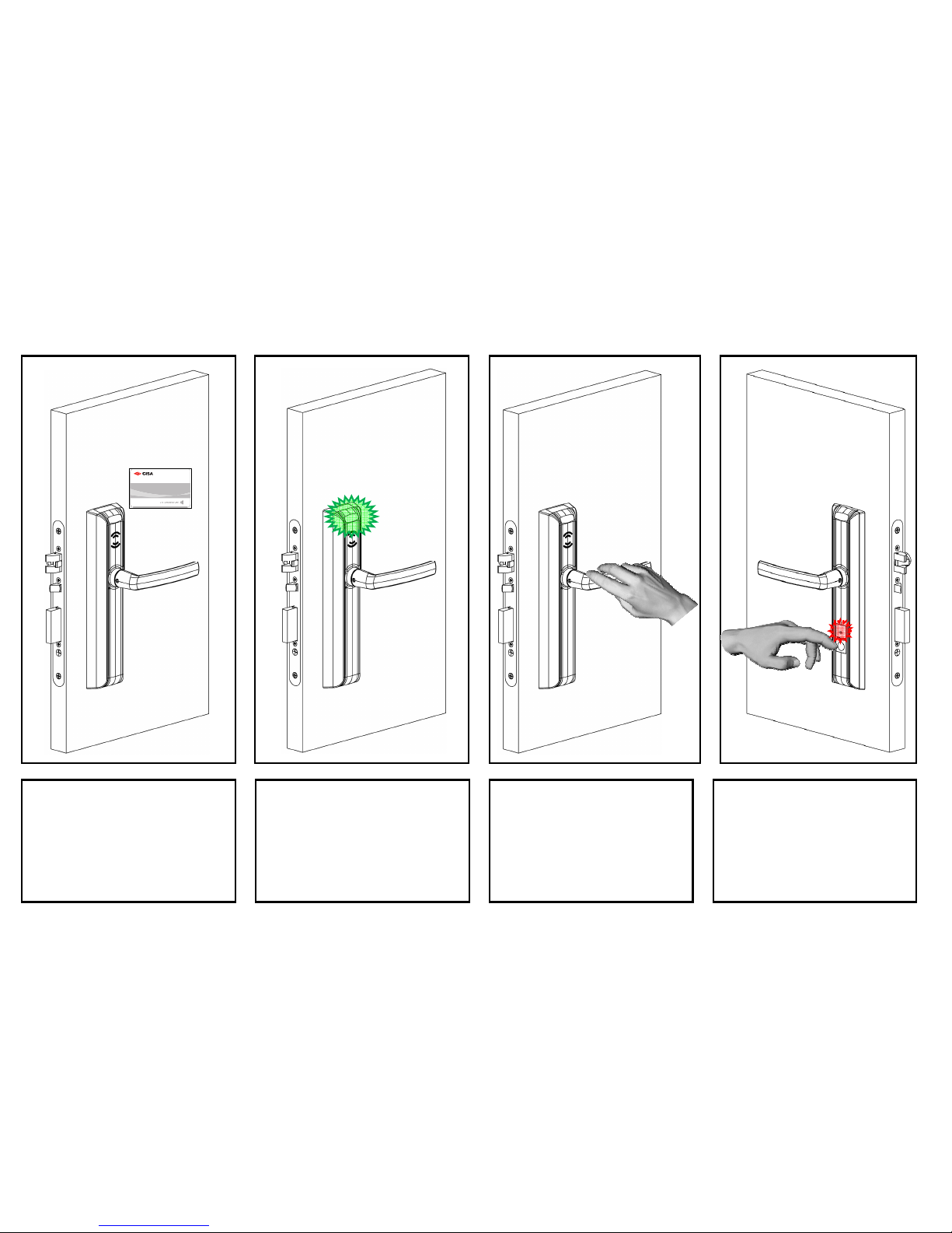
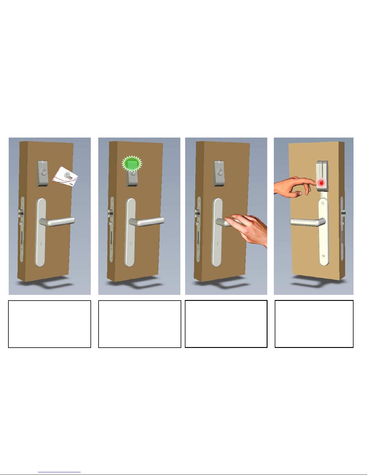
Keep the card close to the reader
for 1 second, in order to allow a
correct communication.
2222
Wait for the lock to give green
blinks: this is the signal of a correct
card reading.
3333
Rotate the knob/external handle,
in order to open the lock, before
the delay opening time expires
(5 seconds default).
4444
Once entered the room, if you
want to enable the Privacy
function, press the Do Not
Disturb button, which turns red.
Page 5
ESIGNO_SYSTEM_USER_MANUAL_101.DOCX 5/71
OOOOPERATING THE
PERATING THE PERATING THE
PERATING THE E
EEE----CCC
CYLINDER
YLINDERYLINDER
YLINDER
1111
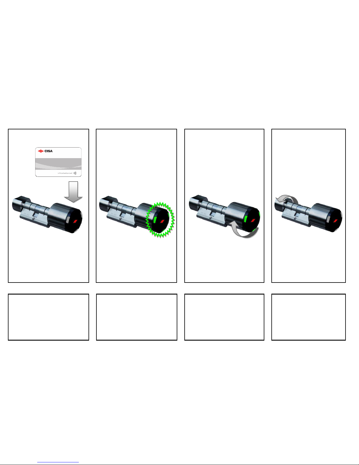
Keep the card close to the
E-Cylinder for 1 second,
in order to allow a correct
communication.
2222
Wait for the E-Cylinder to give
green blinks: this is the signal
of a correct card reading.
3333
Rotate the knob, in order to open
the lock, before the delay opening
time expires
(5 seconds default).
4444
Once entered the room, to
double lock the door, rotate
the internal knob.
Page 6
ESIGNO_SYSTEM_USER_MANUAL_101.DOCX 6/71
OOOOPERATING THE
PERATING THE PERATING THE
PERATING THE W
WW
WALL
ALL ALL
ALL R
RR
READER
EADEREADER
EADER
1111
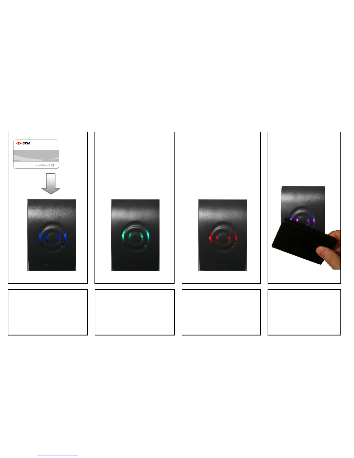
Keep the card close to the wall
reader for 1 second, in order to
allow a correct communication.
2222
Wait for the wall reader to give
green blinks: this is the signal of a
correct card reading. The relay
activates coherently.
3333
If the presented card is not valid,
the wall reader gives three red
blinks.
4444
When the eSIGNO mouse is
presented to the wall reader, it
turns blue and purple.
Page 7
ESIGNO_SYSTEM_USER_MANUAL_101.DOCX 7/71
OOOOPERATING THE
PERATING THE PERATING THE
PERATING THE W
WW
WAVE
AVE AVE
AVE M
MM
MODE
ODE ODE
ODE L
LL
LOCK
OCKOCK
OCK
1111
Keep the card close to the reader
for 1 second, in order to allow a
correct communication.
2222
Wait for the lock to give green
blinks: this is the signal of a correct
card reading.
3333
Rotate the knob/external handle,
in order to open the lock, before
the delay opening time expires (5
seconds default).
4444
Once entered the room, if you
want to enable the Privacy
function, press the Do Not
Disturb button, which turns red.
Page 8
ESIGNO_SYSTEM_USER_MANUAL_101.DOCX 8/71
eeeeSIGNO
SIGNOSIGNO
SIGNO
M
MM
MOBILE
OBILEOBILE
OBILE
e
ee
eSIGNO
SIGNOSIGNO
SIGNO
M
MM
MOBILE
OBILE OBILE
OBILE D
DD
DEVICE
EVICEEVICE
EVICE
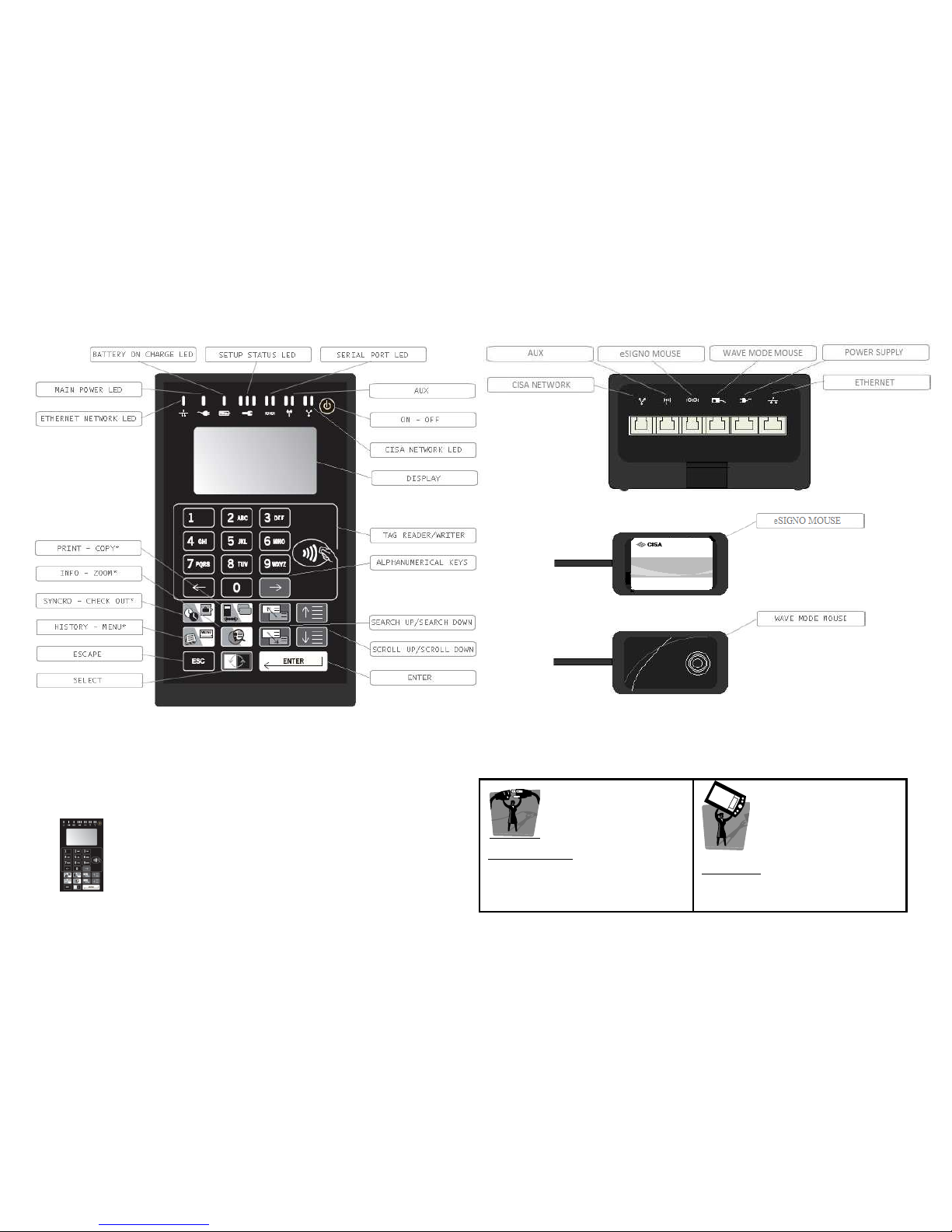
Encoder mode
Encoder modeEncoder mode
Encoder mode: to read, issue and
search for cards and to
communicate with your own pc
through the provided software.
HHI mode
HHI modeHHI mode
HHI mode:::: to configure and
synchronize the locks and to read
the lock audit trails.
* Double function button
: the function varies according to the device working mode
The
eSIGNO
mobile can be used in two different modes:
Page 9
ESIGNO_SYSTEM_USER_MANUAL_101.DOCX 9/71
EEEENCODER
NCODER NCODER
NCODER /
//
/
HHI
HHIHHI
HHI
L
LL
LOGIN
OGIN OGIN
OGIN
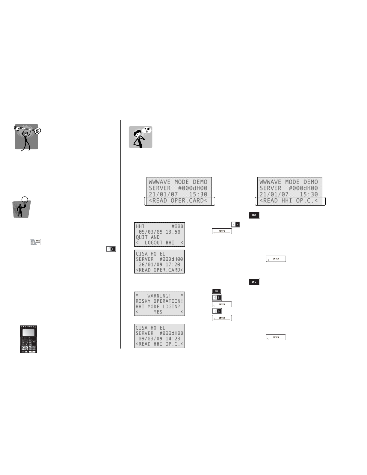
Before doing any operation log on to the
eSIGNO encoder with the operator card.
TIP
TIPTIP
TIP
To change the operator password:
• log on to the encoder;
• read the operator card;
• press ;
• switch to Display/Modify Password with ;
• type the new password, overwriting the old
one.
eeeeSIGNO
SIGNOSIGNO
SIGNO
MMMMOBILE
OBILE OBILE
OBILE D
DD
DEVICE
EVICEEVICE
EVICE
ENCODER MODE OR HHI MODE
ENCODER MODE OR HHI MODEENCODER MODE OR HHI MODE
ENCODER MODE OR HHI MODE ????
When switching on the ESIGNO Mobile, before doing any operation, check if the device is in Encoder
stand-by mode or in HHI stand-by mode.
ENCODER STAND
ENCODER STANDENCODER STAND
ENCODER STAND----BY MODE
BY MODEBY MODE
BY MODE
HHI STAND BY MODE
HHI STAND BY MODEHHI STAND BY MODE
HHI STAND BY MODE
To switch from HHI mode to Encoder mode, simply press and follow the steps below:
• navigate with to the Logout HHI option;
• press ;
• select Yes. The ESIGNO Mobile device switches to Encoder mode;
•
move the operator card above the tag reader of the device;
• type your password and press : you are now logged in
Encoder mode.
To switch from Encoder mode to HHI mode, simply press and follow the steps below:
•
press once again;
• press to answer Yes to the Are You Sure? question, then
press
• press to answer Yes to the HHI Mode Login? question, then
press
• move the operator card above the tag reader of the device;
• type your password and press : you are now logged in
HHI mode.
Page 10
ESIGNO_SYSTEM_USER_MANUAL_101.DOCX 10/71
KKKKEYBOARD
EYBOARDEYBOARD
EYBOARD
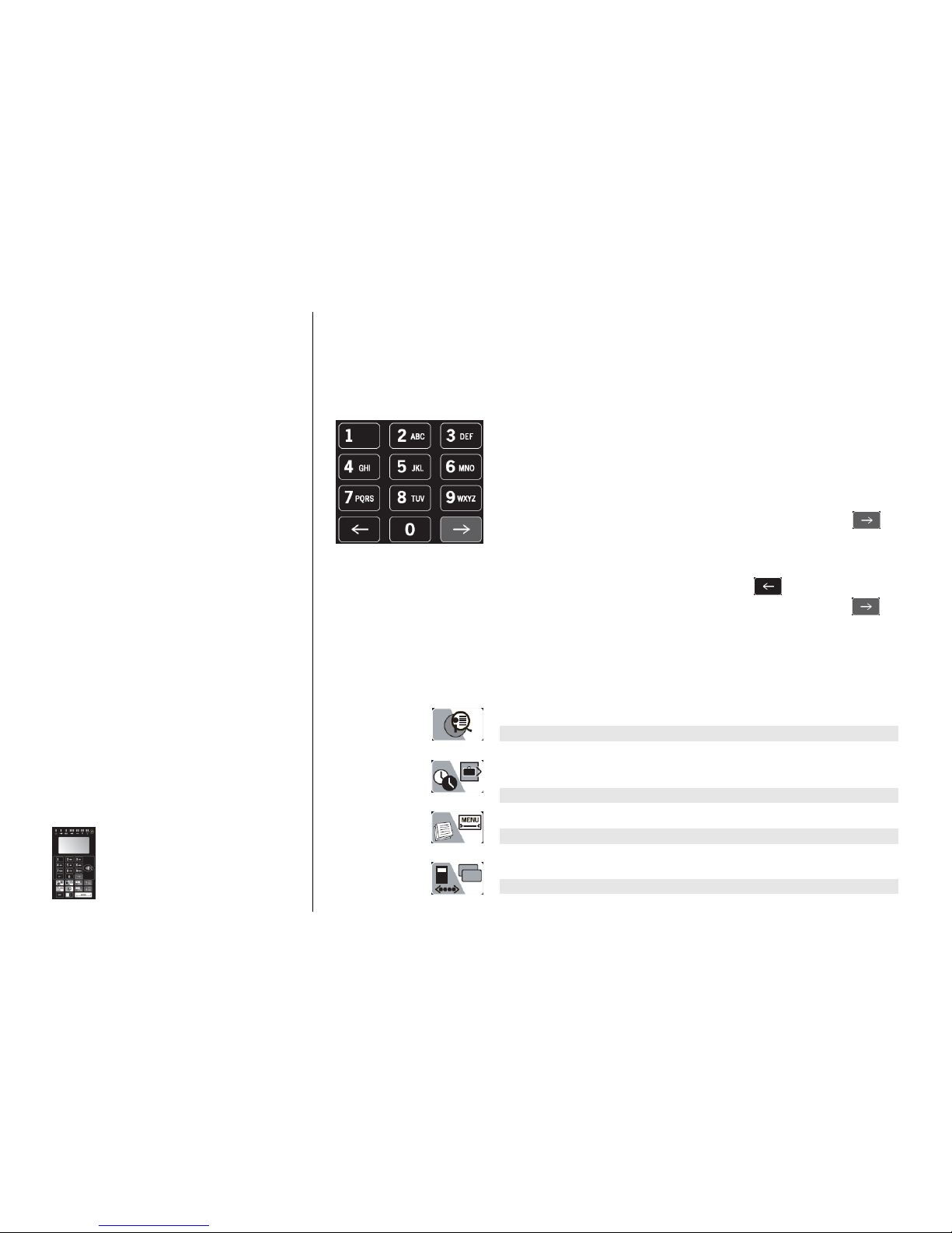
The ESIGNO Mobile provides an enhanced
keyboard, featuring a group of multifunctional
keys whose function depends upon the cursor
position and the working mode (Encoder or
HHI).
eeeeSIGNO
SIGNOSIGNO
SIGNO
MMMMOBILE
OBILE OBILE
OBILE D
DD
DEVICE
EVICEEVICE
EVICE
ALPHANUMERIC KEYS
ALPHANUMERIC KEYSALPHANUMERIC KEYS
ALPHANUMERIC KEYS
The buttons from 1 to 9 can be used to input either letters or digits in
text or numeric fields:
• the first time you press one of these buttons a digit is displayed;
• with the following pressings of the same key, the letters printed on
the button are then displayed;
• at the end of each sequence, another pressing of the button makes
the sequence start again.
If you need to compose a word made of more than 1 character:
• select the first character by pressing the proper button;
• if the second character is listed in the same button, press or
wait 1 second for the cursor to automatically move into next
position; instead, if the second character is contained in another
key, simply press it to insert the character into next position;
• to erase the last character displayed, press ;
• to leave a blank space or to move to the next position press .
DOUBLE FUNCTION KEYS
DOUBLE FUNCTION KEYSDOUBLE FUNCTION KEYS
DOUBLE FUNCTION KEYS
The function of these buttons depends upon the ESIGNO Mobile
working mode, i.e. Encoder (white background) or HHI (grey
background).
Enhanced display
Enhanced displayEnhanced display
Enhanced display: to display all the card details.
Info
InfoInfo
Info: to retrieve information from the locks.
Check
CheckCheck
Check----out
outout
out: to check-out the displayed guest card (this will only make
the card inactive, but it will not cancel it from the database).
Synchro
SynchroSynchro
Synchro: used to synchronize the locks with the HHI.
Menu
MenuMenu
Menu: to access to the encoder menu.
Audit trail readout
Audit trail readoutAudit trail readout
Audit trail readout: to read the operations performed on a lock.
Copy guest card
Copy guest cardCopy guest card
Copy guest card: to quickly copy a guest card.
Print
PrintPrint
Print: to print information stored in memory, using a PC.
Page 11
ESIGNO_SYSTEM_USER_MANUAL_101.DOCX 11/71
C
CC
CARD
ARD ARD
ARD T
TT
TYPES
YPESYPES
YPES
EEEENCODER
NCODER NCODER
NCODER M
MM
MODE
ODE ODE
ODE
CCCCARD
ARD ARD
ARD O
OO
OPERATIONS
PERATIONSPERATIONS
PERATIONS
CARD TYPE
CARD TYPECARD TYPE
CARD TYPE WHAT I
WHAT IWHAT I
WHAT IS
S S
S IT
IT IT
IT FOR
FORFOR
FOR
GUEST
GUESTGUEST
GUEST FOR A GUEST TO ACCESS THE NORMAL LOCK OF A ROOM
STAFF
STAFFSTAFF
STAFF
USED BY HOTEL STAFF MEMBERS
USER
USERUSER
USER
TO ACCESS SPECIAL SERVICES CONTROLLED BY UTILITY LOCKS
EMERGENCY
EMERGENCYEMERGENCY
EMERGENCY
TO BE USED IN CASE OF ENCODING STATIONS MALFUNCTION
DANGER
DANGERDANGER
DANGER
TO BE USED IN CASE OF DANGER, OPENS ALL THE DOORS
REVERSE DANGER
REVERSE DANGERREVERSE DANGER
REVERSE DANGER
TO REVERSE DANGER FUNCTION
LOCKOUT
LOCKOUTLOCKOUT
LOCKOUT
TO LOCK OUT DIFFERENT CARD CATEGORIES
REVERSE LOCKOUT
REVERSE LOCKOUTREVERSE LOCKOUT
REVERSE LOCKOUT
TO REVERSE LOCKOUT FUNCTION
ONE SHOT
ONE SHOTONE SHOT
ONE SHOT
TO BE USED FOR MAINTENANCE, OPENS THE DOOR ONLY ONCE
CLC
CLCCLC
CLC
TO INSERT IN LOCK MEMORY OTHER CARDS, WHICH WILL OPEN DOOR
OPERATOR
OPERATOROPERATOR
OPERATOR
TO WORK WITH THE ENCODING STATION
Page 12
ESIGNO_SYSTEM_USER_MANUAL_101.DOCX 12/71
GGGGUEST
UESTUEST
UEST
(1)
(1)(1)
(1)
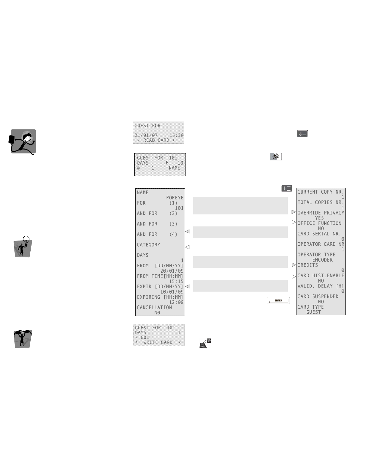
A guest card does not contain only essential
information like room number, guest name and
stay duration: many other features can be
inserted into it, depending on the necessity:
• Opening up to 4 doors with the same
guest card;
• Regulating the use of hotel utilities;
• Enabling particular functions;
• Setting the time validity of the card.
TIP
TIPTIP
TIP
• In order to issue more copies of the same
guest card, move the cursor in the # field and
type in the number of copies desired. The
Current copy number field says which copy
the physical card represents.
• To prepare cards in advance, simply change
the beginning and end of validity dates.
EEEENCODER
NCODER NCODER
NCODER M
MM
MODE
ODEODE
ODE
CCCCARD
ARD ARD
ARD O
OO
OPERATIONS
PERATIONSPERATIONS
PERATIONS
1111
Type the room number, the guest stay duration, the number of
needed copies and the guest’s name, pressing after each field.
2222
To change other parameters, press
3333
Navigate through the fields by pressing
To issue a card which opens the
correspondent door(s) also if the privacy is
on, change this value.
Setting “Yes” in this field, you can activate
the Office function.
To issue a card to open up to 4 doors,
insert the doors numbers in this point.
If the guest has the right to access some
particular hotel utilities, type here the name
of the correspondent category.
This is the number of credits the guest can
spend using utilities inside the hotel.
By enabling this voice, it is then possible to
register the operations of the card.
By changing these values, you can set the
time validity of the card you are issuing.
Confirm your choices by pressing
4444
Move the card over the tag reader/writer on the encoder and wait
for the short beep.
Card writing is now completed!
Page 13
ESIGNO_SYSTEM_USER_MANUAL_101.DOCX 13/71
GGGGUEST
UESTUEST
UEST
((((2222))))
Beds function
Beds functionBeds function
Beds function is a special configuration that
allows issuing up to 7 guest cards for the same
room with different time validities.
Every new guest card for a bed invalidates the
previous one for the same bed; every new guest
card for the whole room invalidates all the guest
cards for the single beds.
This feature is available only if it has been set in
the Configurator during plant installation.
TIP
TIPTIP
TIP
It is very important to understand the difference
between:
• Card Copies
Card CopiesCard Copies
Card Copies: they always have the same
validity and when one card opens a door,
the copies will open it as well;
• Cards associated t
Cards associated tCards associated t
Cards associated to Beds
o Bedso Beds
o Beds: they can have
different time validity, and be checked out or
cancelled separately.
EEEENCODER
NCODER NCODER
NCODER M
MM
MODE
ODE ODE
ODE
CCCCARD
ARD ARD
ARD O
OO
OPERATIONS
PERATIONSPERATIONS
PERATIONS
BBBB
EDS
EDS EDS
EDS
FFFF
UNCTION
UNCTIONUNCTION
UNCTION
EXAMPLE
EXAMPLEEXAMPLE
EXAMPLE
Monday
MondayMonday
Monday
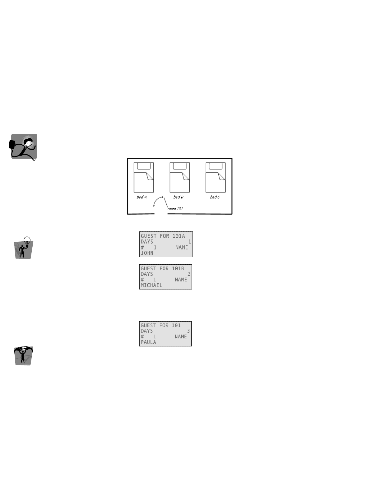
Here is what the receptionist has to do to correctly use the beds function:
John checks in on Monday till Tuesday (at 12:00); he takes the bed A
in the room 101.
Michael checks in on Monday till Wednesday (at 12:00); he takes the
bed B in the room 101.
Both John and Michael can access simultaneously the room 101 during their card time validity
without invalidating their own cards each other.
Tuesday
TuesdayTuesday
Tuesday
Paula checks in for 3 days into room 101, but she would like to have
the whole room for herself.
When Paula uses her card in the lock 101, she invalidates John's and Michael's card.
Page 14
ESIGNO_SYSTEM_USER_MANUAL_101.DOCX 14/71
S
SS
STAFF
TAFFTAFF
TAFF
CCCCARDS
ARDSARDS
ARDS (1)
(1)(1)
(1)
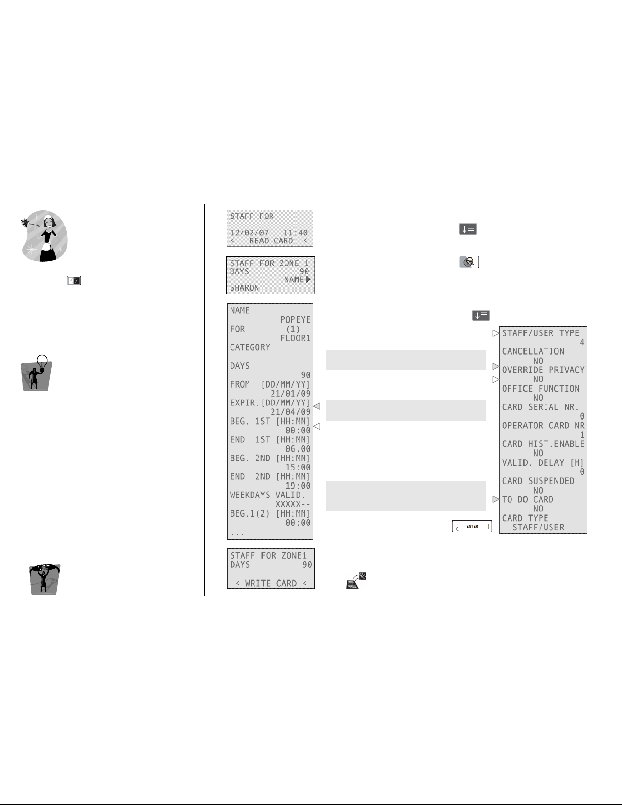
Once logged into the system, to write staff
cards, press and select STAFF FOR.
TIP
TIPTIP
TIP
To create a Staff card, you have to define:
• the Zones and the doors that belong to
them while creating the plant.
• the hierarchy level to define the rights of
the operator (e.g. level 6 operator can
write guest cards only)
EEEENCODER
NCODER NCODER
NCODER M
MM
MODE
ODEODE
ODE
CCCCARD
ARD ARD
ARD O
OO
OPERATIONS
PERATIONSPERATIONS
PERATIONS
1111
Type the zone the card will be valid for, the days of validity and the
name of the staff member, pressing after each field.
2222
To change other parameters, press
3333
Navigate through the fields by pressing
This is Staff type (1 to 4), assigned
depending on the selected zone.
To issue a card which opens the door(s)
also if the privacy is on, change this value.
Enable to activate the Office function
inserting the card twice into an Office lock.
By setting these fields you can manage the
time validity of the card you are issuing.
To set working time and days: there are 4
time modules; inside each, it is possible to
set 2 working periods for each day of
module’s validity with 15 minutes precision
(card is valid in X-marked days only).
This field is active only if the Recoding
Function is active. After setting Yes in this
field, it is then possible to recode the card.
Confirm your choices by pressing
4444
Move the card over the tag reader/writer on the encoder and wait
for the short beep.
Card writing is now completed!
Page 15
ESIGNO_SYSTEM_USER_MANUAL_101.DOCX 15/71
SSSSTAFF
TAFF TAFF
TAFF
C
CC
CARDS
ARDS ARDS
ARDS (2)
(2)(2)
(2)
Once logged into the system, to write staff
cards, press and select STAFF FOR.
TIP
TIPTIP
TIP
One zone is created by default in every plant:
the MASTER zone, which includes all the locks in
the hotel. A Staff card for MASTER zone has the
Override privacy function disabled by default.
EEEENCODER
NCODER NCODER
NCODER M
MM
MODE
ODEODE
ODE
C
CC
CARD
ARD ARD
ARD O
OO
OPERATIONS
PERATIONSPERATIONS
PERATIONS
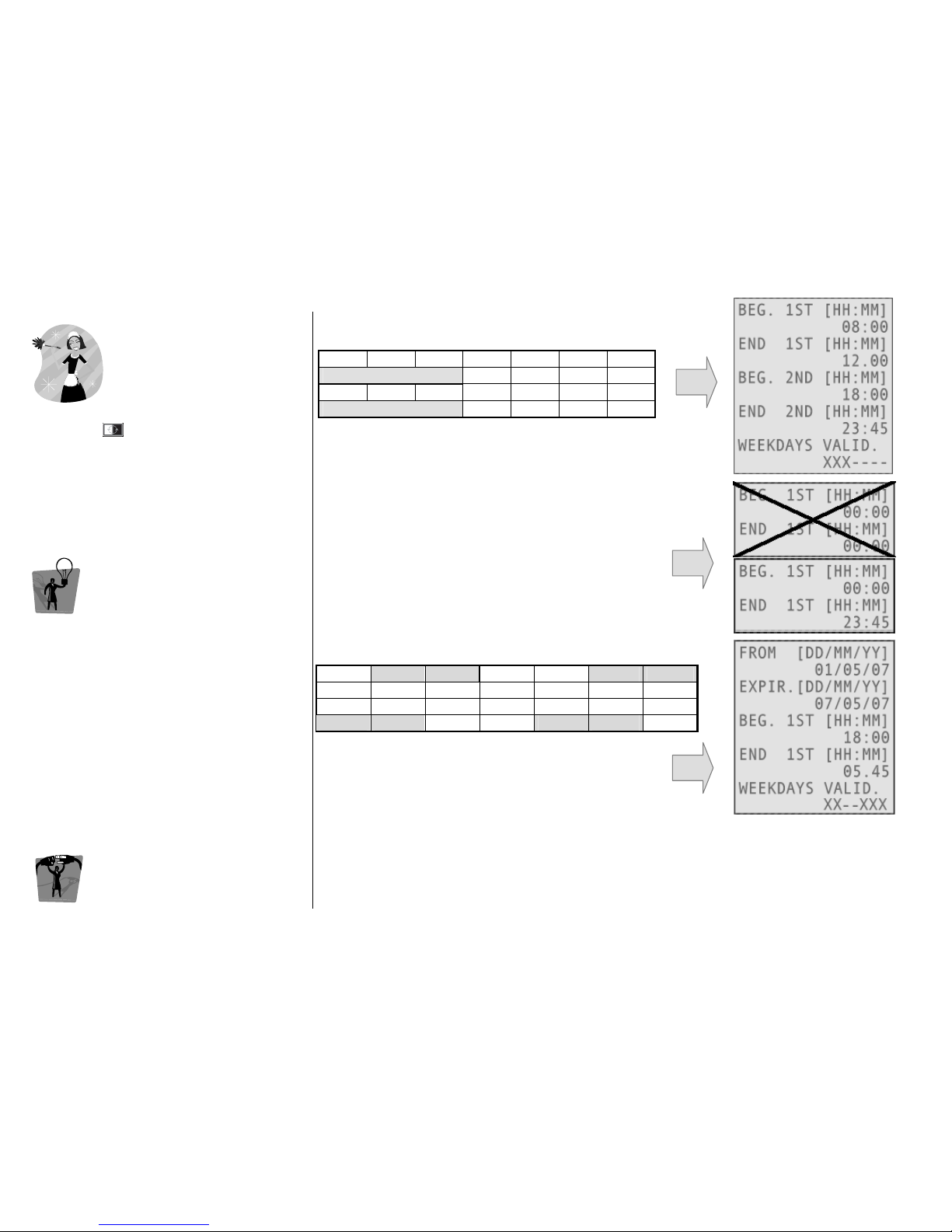
STAFF CARD VALIDITY
STAFF CARD VALIDITYSTAFF CARD VALIDITY
STAFF CARD VALIDITY
Validity precision is 15 minutes:
Validity precision is 15 minutes:Validity precision is 15 minutes:
Validity precision is 15 minutes:
• the encoding station rounds to the previous 15 minutes:
12:13 becomes 12:00
• the end of validity includes the following 15 minutes:
first shift starts at 08:00 and will end at 12:15
second shift starts at 18:00 and will end at 24:00
• if the beginning and the end of validity time are both
the same, there is no validity. To have a card with 24
hours of validity, it is necessary to considerate the time
span of 15 minutes
WORKING HOURS OVER MIDNIGHT
WORKING HOURS OVER MIDNIGHTWORKING HOURS OVER MIDNIGHT
WORKING HOURS OVER MIDNIGHT
MON 1 TUE 2 WED 3 THU 4 FRI 5 SAT 6 SUN7
Date of validity: 1 May 2007 from time 18:00
Date end validity: 7 May 2007 until time 06:00
TYPES OF STAFF
TYPES OF STAFFTYPES OF STAFF
TYPES OF STAFF
• The type (possibilities are 1,2,3,4) is assigned automatically from the system and depends upon
the Zone that is assigned to the card.
• Type is important with the LOCKOUT CARDS in order to select which one has to be blocked.
• STAFF type 3 is also able to have the TIDY UP function. Operators are STAFF type 4.
MON TUE WED THU FRI SAT SUN
08:00 – 12:15
18:00 – 24:00
Page 16
ESIGNO_SYSTEM_USER_MANUAL_101.DOCX 16/71
U
UU
USER
SERSER
SER
CCCCARDS
ARDSARDS
ARDS
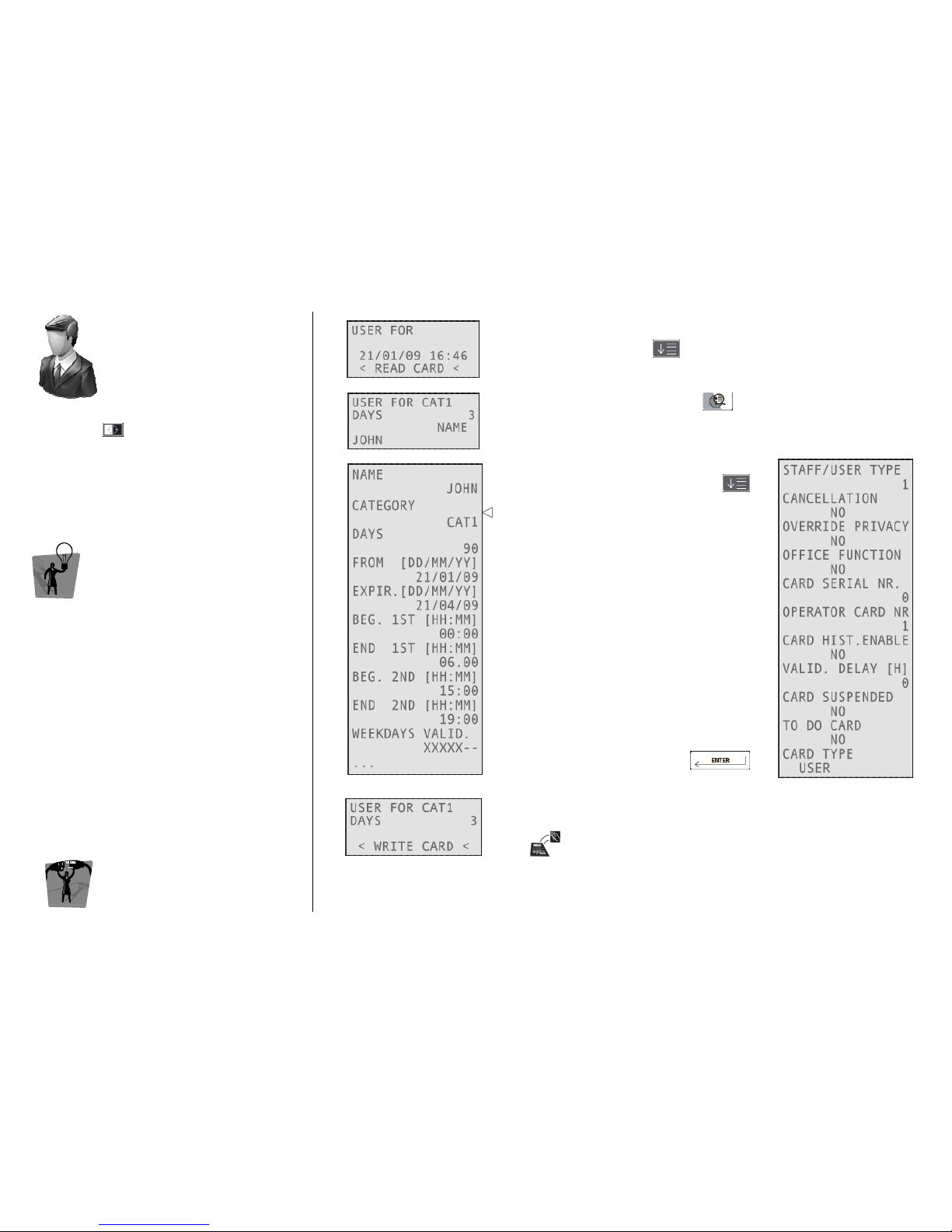
Once logged into the system, to write user
cards, press and select USER FOR.
TIP
TIPTIP
TIP
To create a User card, you have to define the
Categories and the Utility doors that belong to
them.
EEEENCODER
NCODER NCODER
NCODER M
MM
MODE
ODE ODE
ODE
CCCCARD
ARD ARD
ARD O
OO
OPERATIONS
PERATIONSPERATIONS
PERATIONS
1111
Type the category the card will be valid for, the days of validity and the
name of the user, pressing after each field.
2222
To change other parameters, press
3333
Navigate through the fields by pressing
This is the previously selected Category.
All the other fields are the same with
respect to Staff cards.
Confirm your choices by pressing
4444
Move the card over the tag reader/writer on the encoder and wait
for the short beep.
Card writing is now completed!
Page 17
ESIGNO_SYSTEM_USER_MANUAL_101.DOCX 17/71
O
OO
OPERATOR
PERATOR PERATOR
PERATOR
CCCCARDS
ARDSARDS
ARDS
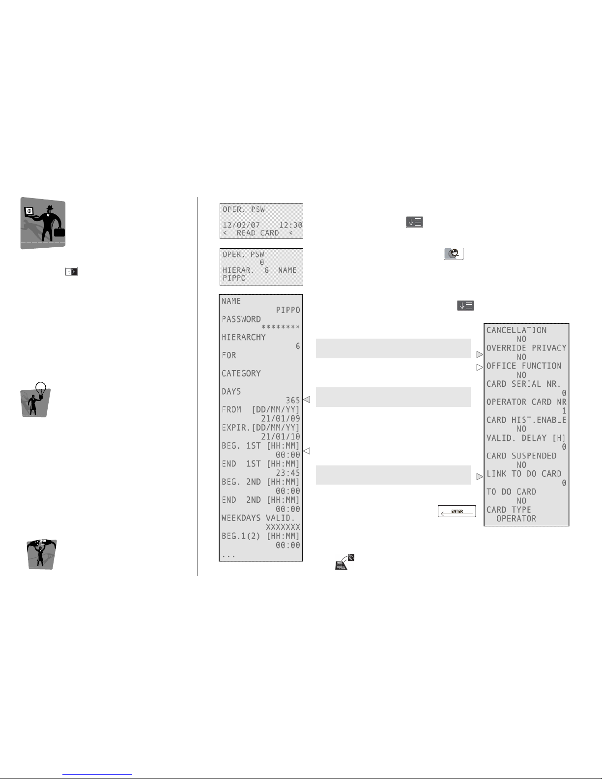
Once logged into the system, to write operator
cards, press and select OPER. PWD.
An Operator card allows the operator to work
on the encoding station; depending on the
Hierarchy, he will be enabled to use particular
functions. If the card is allowed
to access the locks, it will have the same features
as a STAFF card with type 4.
TIP
TIPTIP
TIP
It is possible to disable a staff or operator card to
access a room by putting it on the black list,
keeping the cancellation card close to the lock.
Creating the cancelling card for an operator
Creating the cancelling card for an operator Creating the cancelling card for an operator
Creating the cancelling card for an operator
automatically disables the operator card to work
automatically disables the operator card to work automatically disables the operator card to work
automatically disables the operator card to work
on the encoding station.
on the encoding station.on the encoding station.
on the encoding station.
EEEENCODER
NCODER NCODER
NCODER M
MM
MODE
ODEODE
ODE
CCCCARD
ARD ARD
ARD O
OO
OPERATIONS
PERATIONSPERATIONS
PERATIONS
1111
Type the chosen password, the hierarchy level of the card and the
operator name, pressing after each field.
2222
To change other parameters, press
3333
Navigate through the fields by pressing
To issue a card which opens the door(s)
also if the privacy is on, change this value.
Enable to activate the Office function
inserting the card twice into an Office lock.
By setting these fields you can manage the
time validity of the card you are issuing.
To set working time and days: there are 4
time modules; inside each is possible to set
2 working period for each day of module’s
validity with 15 minutes precision (card is
valid in X-marked days).
This field is active only if the Recoding
Function is active.
Confirm your choices by pressing
Move the card over the tag reader/writer on the encoder and wait
for the short beep.
Card writing is now completed!
Page 18
ESIGNO_SYSTEM_USER_MANUAL_101.DOCX 18/71
E
EE
EMERGENCY
MERGENCY MERGENCY
MERGENCY
C
CC
CARDS
ARDSARDS
ARDS
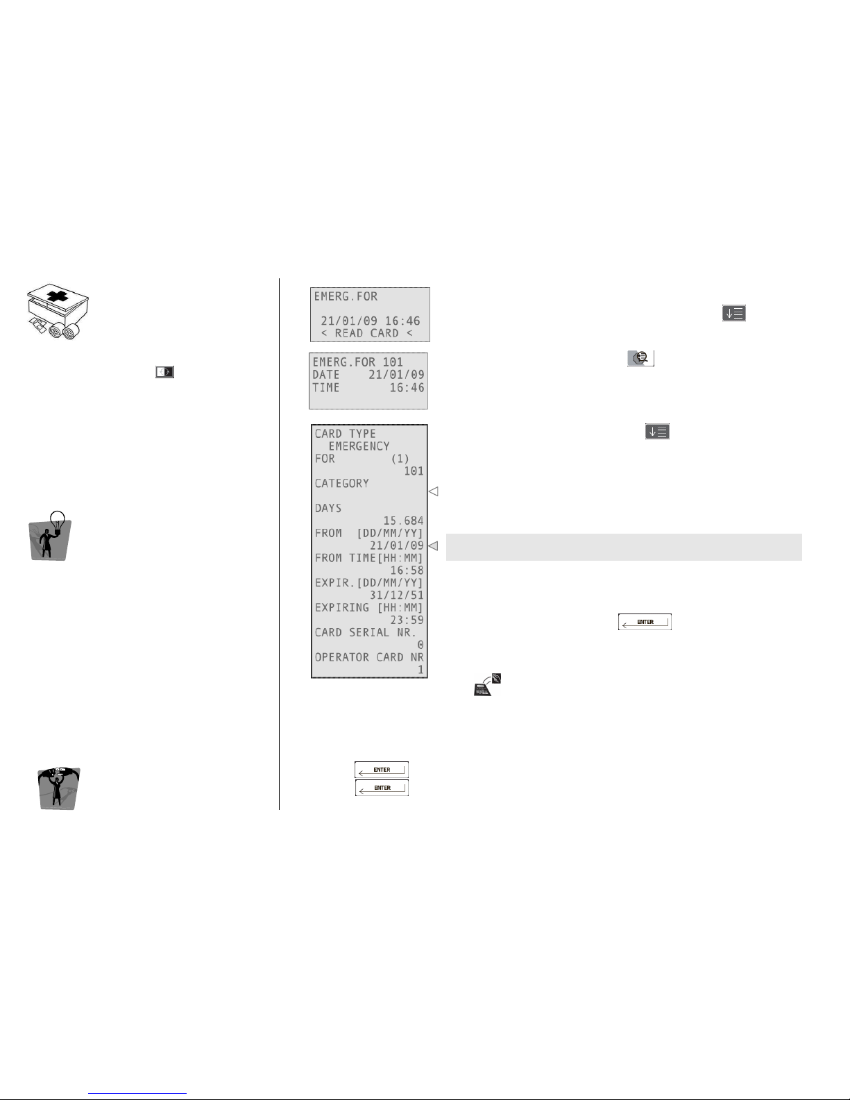
Once logged into the system, to write
emergency cards, press and select
EMERG. FOR
An Emergency card opens the door for which it
has been programmed, withdrawing even the
deadbolt, should the guest have drawn it on
privacy. These cards can be created only for a
single room.
TIP
TIPTIP
TIP
One card for each guest room should be kept at
the reception desk safety box and should be
used only in case the encoding system fails,
giving it to the guest and must be taken back
upon check-out.
An emergency card with a later beginning of
validity will invalidate the previous one when
approached to the lock.
EEEENCODER
NCODER NCODER
NCODER M
MM
MODE
ODEODE
ODE
CCCCARD
ARD ARD
ARD O
OO
OPERATIONS
PERATIONSPERATIONS
PERATIONS
1111
Type the number of the room you are issuing an emergency card for
and date and time of beginning of its validity, pressing after
each field.
2222
To change other parameters, press
3333
Navigate through the fields by pressing
It is possible to issue also emergency cards for categories, to be used in
the same cases of a room emergency card.
By setting these fields you can manage the time validity of the card
you are issuing. Note that an emergency card has an infinite validity.
Confirm your choices by pressing
Move the card over the tag reader/writer on the encoder and wait
for the short beep.
Card writing is now completed!
AUTOMATIC CREATION OF EMERGENCY CARDS SET
AUTOMATIC CREATION OF EMERGENCY CARDS SETAUTOMATIC CREATION OF EMERGENCY CARDS SET
AUTOMATIC CREATION OF EMERGENCY CARDS SET
• start from a room number (e.g. 101);
• encode the card;
• press (the system will automatically present as input the following room);
• press to encode the next card.
Page 19
ESIGNO_SYSTEM_USER_MANUAL_101.DOCX 19/71
LLLLOCKOUT
OCKOUT OCKOUT
OCKOUT /
///
RRRREVERSAL
EVERSAL EVERSAL
EVERSAL L
LL
LOCKOUT
OCKOUTOCKOUT
OCKOUT
CCCCARDS
ARDSARDS
ARDS
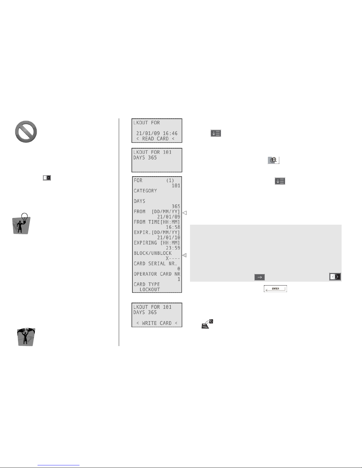
This kind of card permits to lock out (or reverse
lock out) other different card categories, like
guest or staff cards. Once logged into the
system, to write lock out (or reverse lock out)
cards, press and select LKOUT FOR (or
REV.LOCK.).
TIP
TIPTIP
TIP
These cards can be created only for a specified
zone of lockout. If you lock out all card types, the
only one allowed to enter is an emergency card.
EEEENCODER
NCODER NCODER
NCODER M
MM
MODE
ODEODE
ODE
CCCCARD
ARD ARD
ARD O
OO
OPERATIONS
PERATIONSPERATIONS
PERATIONS
1111
Type the zone the card will be valid for and the days of validity,
pressing after each field.
2222
To change other parameters, press
3333
Navigate through the fields by pressing
By setting these fields you can manage the time validity of the card
you are issuing.
The card groups which can be locked out (or reverse locked out) are:
• Guest
• Staff 1
• Staff 2
• Staff 3
• Staff 4 and Operators
In a lockout (reverse lockout) card, X indicates the kind of cards you
are able to block (unblock).
To change values, move with and select (or unselect) with
Confirm your choices by pressing
4444
Move the card over the tag reader/writer on the encoder and wait
for the short beep.
Card writing is now completed!
Page 20
ESIGNO_SYSTEM_USER_MANUAL_101.DOCX 20/71
O
OO
ONE
NE NE
NE S
SS
SHOT
HOT HOT
HOT
CCCCARDS
ARDSARDS
ARDS
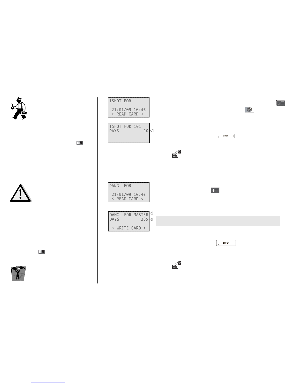
These cards are issued in special cases (needed
maintenance inside a room) and allow to open
the door only once. Once logged into the
system, to write One Shot cards, press and
select 1SHOT FOR.
DDDDANGER
ANGER ANGER
ANGER /
///
RRRREVERSAL
EVERSAL EVERSAL
EVERSAL D
DD
DANGER
ANGERANGER
ANGER
CCCCARDS
ARDSARDS
ARDS
• Danger card
Danger cardDanger card
Danger card: opens all the doors (overriding
the privacy as well) and keeps the locks in the
opening state until a reversal danger card is
kept close to them. This allows guest and staff
to get out quickly in events of danger and
prevents the door from closing;
• Reversal
Reversal Reversal
Reversal DDDDanger
angeranger
anger: reverses danger function.
• Once logged into the system, to write these
cards, press and select DANG. FOR or
REV.DANG.
EEEENCODER
NCODER NCODER
NCODER M
MM
MODE
ODEODE
ODE
CCCCARD
ARD ARD
ARD O
OO
OPERATIONS
PERATIONSPERATIONS
PERATIONS
1111
Type the room number or the zone and the days of validity, press
ing
after each field. To change other parameters, press
2222
The time validity specifies the duration of the card; it will, however,
open the correspondent lock only once.
Confirm your choices by pressing
Move the card over the tag reader/writer on the encoder and wait
for the short beep.
Card writing is now completed!
1111
Press any numeric button, then and finally the days of validity.
2222
It is possible to issue Danger (or Reverse Danger) cards for the Master
zone only, which means that these cards are valid for all the rooms.
By setting these fields you can manage the time validity of the card
you are issuing.
A newly created card of both types invalidates the previous one if it is
approached to the locks.
Confirm your choices by pressing
Move the card over the tag reader/writer on the encoder and wait
for the short beep.
Card writing is now completed!
Page 21
ESIGNO_SYSTEM_USER_MANUAL_101.DOCX 21/71
CLC
CLCCLC
CLC
CCCCARDS
ARDSARDS
ARDS
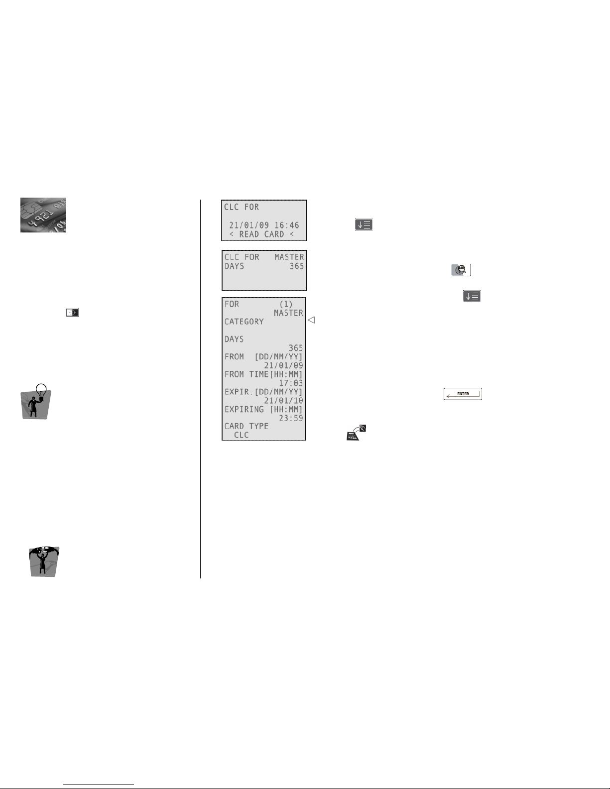
This kind of card permits the access of a lock’s
memory and the memorization of any other
card, encoded by the CISA system, onto it. In this
way the door will be enabled to open with
the new contactless card memorized in the lock.
Once logged into the system, to write CLC
cards, press and select CLC FOR.
TIP
TIPTIP
TIP
This function is useful for example when a guest
has an his own contactless card (of another
hotel or of other systems) and he wants to open
with his card without having a new one.
EEEENCODER
NCODER NCODER
NCODER M
MM
MODE
ODEODE
ODE
CCCCARD
ARD ARD
ARD O
OO
OPERATIONS
PERATIONSPERATIONS
PERATIONS
1111
Type the zone the card will be valid for and the days of validity,
pressing after each field.
2222
To change other parameters, press
3333
Navigate through the fields by pressing
• CLC cards can be created only for a specified zone.
• Up to three different cards can be memorized as guest cards with
CLC card on each lock: if you attempt to memorize the fourth card,
the lock will display three red blinks.
• To disable the memorized cards it is necessary to keep a new guest
card close to the lock (with start of validity later than the time of
memorization), created from the encoding station.
Confirm your choices by pressing
Move the card over the tag reader/writer on the encoder and wait
for the short beep
Card writing is now completed!
HOW TO MEMORIZE A CARD WITH A CLC
HOW TO MEMORIZE A CARD WITH A CLCHOW TO MEMORIZE A CARD WITH A CLC
HOW TO MEMORIZE A CARD WITH A CLC
• Keep the CLC close to the lock, which responds with 2 green blinks;
• keep the card to be memorized close to the lock, which responds with 2 red & green blinks (this
will be recorded as memorized cards on the history readout.);
• to add more cards repeat the same operation.
MANAGING SPECIAL GROUPS
MANAGING SPECIAL GROUPSMANAGING SPECIAL GROUPS
MANAGING SPECIAL GROUPS
Example: students + professor.
The professor is allowed to enter all the student rooms, but students can only enter individual rooms:
to accomplish this, in each room, memorize the professor card and the specific student card.
Page 22
ESIGNO_SYSTEM_USER_MANUAL_101.DOCX 22/71
AAAACCESS
CCESS CCESS
CCESS T
TT
TARGETS
ARGETSARGETS
ARGETS:
::
:
L
LL
LOCKS
OCKS OCKS
OCKS &
&&
&
Z
ZZ
ZONES
ONESONES
ONES
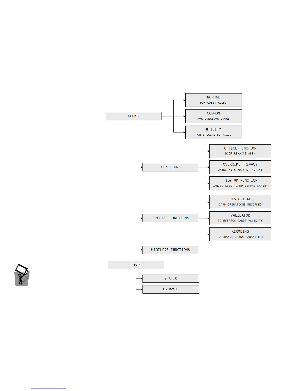
This chapter will present the different types of
Lock
LockLock
Lockssss, along with their features and functions,
and the concept of Zones
ZonesZones
Zones.
AAAACCESS
CCESS CCESS
CCESS T
TT
TARGETS
ARGETSARGETS
ARGETS
Page 23

ESIGNO_SYSTEM_USER_MANUAL_101.DOCX 23/71
L
LL
LOCK
OCK OCK
OCK T
TT
TYPES
YPESYPES
YPES
TIP
TIPTIP
TIP
Examples of cases of use of the three lock types
can be seen in the figure below.
AAAACCESS
CCESS CCESS
CCESS T
TT
TARGETS
ARGETSARGETS
ARGETS
NNNN
ORMAL
ORMALORMAL
ORMAL
A lock for a normal guest room, presents the following features:
• with Guest Cards
Guest CardsGuest Cards
Guest Cards:
only a guest card (or copies of the same) can have access to it, provided that the following
parameters and features are met: plant code, door number, date and time validity, card not
invalidated by another guest card having a later beginning date of validity, guest card not locked
out, card not cancelled;
• with Staff
StaffStaff
Staff CCCCards
ardsards
ards:
any staff card is enabled if the lock is in the zone in which the card is allowed, provided that the
following parameter and features are met: plant code, door belonging to the zone of the card, date
and time (as working hours) validity, guest not in privacy, staff card not locked out, card not
cancelled (up to 20 staff cards can be cancelled).
CCCC
OMMON
OMMONOMMON
OMMON
This kind of lock can be installed to doors giving access to more rooms, on which normal doors are
installed (e.g. corridor door). When initializing the system, a range of door numbers (normal locks) will
be assigned to the common door. Features of the common doors are:
• with Guest Cards
Guest CardsGuest Cards
Guest Cards:
any guest card can have access to it, provided that it has been coded for a door falling within the
interval that has been set when configuring the topological structure. The parameters and features
are the same of a normal door, except that a later guest does not invalidate an earlier one and that
there’s the possibility to cancel up to 20 guest card plus 20 staff card;
• with Staff Cards
Staff CardsStaff Cards
Staff Cards:
any staff card can have access if the lock belongs to its zone. Parameters which are controlled do
not change as compared to those mentioned with reference to normal lock.
UUUU
TILITY
TILITYTILITY
TILITY
These are the locks that give access to special areas or areas of payment in a given plant. It is possible
to associate an utility lock with every additional service offered by the hotel (e.g. sauna, garage, fitness
room), up to 1024 in eSIGNO plants and 2032 in eSIGNO Extended plants.
The utility doors can be grouped in categories, presented in the following chapter. Therefore, each
card is marked by the name of the normal locks it can open and by the category of services it can
have access to.
Page 24

ESIGNO_SYSTEM_USER_MANUAL_101.DOCX 24/71
L
LL
LOCK
OCKOCK
OCK F
FF
FUNCTIONS
UNCTIONSUNCTIONS
UNCTIONS
AAAACCESS
CCESS CCESS
CCESS T
TT
TARGETS
ARGETSARGETS
ARGETS
OOOO
FFICE
FFICE FFICE
FFICE
FFFF
UNCTION
UNCTIONUNCTION
UNCTION
When this function has been programmed into a lock, a valid card with Office Function enabled
approached to the lock has the ability to put it in hold open position.
During the plant configuration, it is possible to choose one of the two following working modes for
the Office Function:
• N
NN
Normal Mode
ormal Modeormal Mode
ormal Mode: to put the lock in office mode, you need to approach twice the card. To exit from
this mode, approach the card again twice;
• T
TT
Toggle
oggleoggle
oggle MMMMode
odeode
ode: just keep once the card close to the lock to toggle the office function.
OOOO
VERRIDE
VERRIDE VERRIDE
VERRIDE
PPPP
RIVACY
RIVACYRIVACY
RIVACY
Privacy function is a useful function for guests inside their room, who can prevent other valid cards
from opening the room door, simply by pressing the Do Not Disturb button on the inner side of the
lock. However, it is possible to select if a card can Override the Privacy function, by enabling this
feature.
• Guest cards have default override privacy;
• Staff cards don’t have this function enabled by default but it is possible to create Staff cards with
override privacy.
TTTT
IDY
IDY IDY
IDY
UUUU
P
P P
P
FFFF
UNCTION
UNCTIONUNCTION
UNCTION
If this function is programmed into the lock during installation, a type 3 Staff card can disable an active
guest card from the lock. These are the steps to be followed to use the Tidy Up Function:
• keep the type 3 Staff card close to the lock, which opens;
• keep the type 3 Staff card close to the lock again; the lock gives 1 red & 1 green blink;
• keep the type 3 Staff card close to the lock again; the lock gives 4 red & 4 green blinks;
• now the guest card is written in the black list and it is no more allowed to enter the room.
This function is useful in case the staff has already cleaned the room at 10:00 am because the guest
has already checked out, but his card is still valid until 12:00 (default checkout time).
Page 25

ESIGNO_SYSTEM_USER_MANUAL_101.DOCX 25/71
LLLLOCK
OCKOCK
OCK
SSSSPECIAL
PECIAL PECIAL
PECIAL F
FF
FUNCTIONS
UNCTIONSUNCTIONS
UNCTIONS
AAAACCESS
CCESS CCESS
CCESS T
TT
TARGETS
ARGETSARGETS
ARGETS
HHHH
ISTORICAL
ISTORICAL ISTORICAL
ISTORICAL
FFFF
UNCTION
UNCTIONUNCTION
UNCTION
If this function has been enabled, each operation made by the card is recorded on its own memory.
Once the memory of the card has been written it is possible to download the list of the operations
with the ESIGNO Mobile in encoder mode.
During the installation of the plant it’s possible to choose two different history recording modalities:
• N
NN
Not
ot ot
ot rewritable
rewritablerewritable
rewritable: the card can record up to 30 operations. If the memory of the card is full and you
pass it on the lock, it will give you three red blinks: in this case, you have to download the history of
the card with the ESIGNO Mobile in encoder mode, using the Load Card History menu.
In this case, each time you have access to an online special lock (e.g. the hotel main entrance), it will
upload the history of the card in order not to lose records.
• R
RR
Rewritable
ewritableewritable
ewritable: the thirty-first operation will be recorded, but it will overwrite the first record. The same
will happen for the subsequent records.
VVVV
ALIDATOR
ALIDATOR ALIDATOR
ALIDATOR
FFFF
UNCTION
UNCTIONUNCTION
UNCTION
This function is active only if, during the configuration of the special lock, the validation function has
been enabled.
VVVValidation
alidationalidation
alidation is a special function that allows to have further control on the validity of issued cards.
In the moment of issuing guest, staff and operators cards, it is possible to set a validation delay: inside
this period of time, the owner of the card has to pass it on a special door (which has been initialized as
VVVValidator
alidatoralidator
alidator), in order to refresh the validity of the card. If the validation time has expired and the card has
not been presented to the special lock, the access rights of the card are not valid anymore: to recover
these rights, the card has to be presented to the validator.
RRRR
ECODING
ECODING ECODING
ECODING
FFFF
UNCTION
UNCTIONUNCTION
UNCTION
This particular function allows you to change some parameters of staff and user cards (e.g. validity,
access targets) without using the encoder but rather through the reader connected to an online
special lock.
• An operator, using the encoder, sends a recoding command to the special lock (e.g. the hotel main
entrance), configured as Validator with the recoding function enabled.
• When the staff (or user) card is read by the reader connected to the special lock, the parameters of
the card will change in compliance with the instruction given by the recoding command.
To use the recoding function, it is necessary to enable the validation function during the initialization
of the special lock.
Page 26
ESIGNO_SYSTEM_USER_MANUAL_101.DOCX 26/71
LLLLOCK
OCKOCK
OCK
WWWWIRELESS
IRELESS IRELESS
IRELESS F
FF
FUNCTIONS
UNCTIONSUNCTIONS
UNCTIONS
AAAACCESS
CCESS CCESS
CCESS T
TT
TARGETS
ARGETSARGETS
ARGETS
RRRR
EMOTE SYSTEM MANAGEM
EMOTE SYSTEM MANAGEMEMOTE SYSTEM MANAGEM
EMOTE SYSTEM MANAGEMENT
ENTENT
ENT
FUNCTION eSIGNO WIRELESS
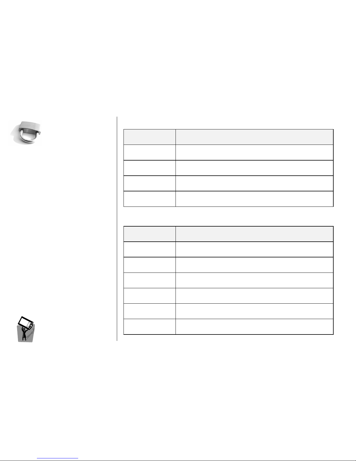
Audit trail retrieval
Access data is available at the central computer: no limits imposed on data
storage in stand-alone locks (latency time: 1min)
Staff card cancellation
The individual staff card can be cancelled from the lock by wireless connection
from reception (latency time: 10min)
Staff Monitoring
A report can be generated automatically to show all accesses by an employee
to any room, a group of rooms or all rooms (latency time: 1min)
Remote door opening Possibility to open the lock by remote command (latency time: 1min)
RRRR
EEEEMOTE DIAGNOSTIC AND
MOTE DIAGNOSTIC AND MOTE DIAGNOSTIC AND
MOTE DIAGNOSTIC AND MAINTENANCE
MAINTENANCEMAINTENANCE
MAINTENANCE
FUNCTION eSIGNO WIRELESS
Door status
If door is left open for more than a pre-set time, a special alert can be issued at
the security office (latency time: 1 min)
Low battery status
The battery level for wireless locks is reported to the computer terminal on
each event on the lock
Accurate timekeeping
Automatic lock synchronization from central station (once a day).
Daylight saving time and Holidays tables (once a week).
Lock settings and
diagnostics
Possibility to perform remote operations: read hardware information, change
lock parameters as opening time, autoprograms, lockout (latency time: 1 min)
Wireless field quality
The wireless field quality for wireless lock is reported to the engineering
computer terminal on each event on the lock
Wireless Analyser tool
Installation tool (eSIGNO Mobile + Analyser antenna) to perform wireless field
analysis for plant installation and maintenance.
Page 27
ESIGNO_SYSTEM_USER_MANUAL_101.DOCX 27/71
LLLLOCK
OCKOCK
OCK
VVVVISUAL
ISUAL ISUAL
ISUAL S
SS
SIGNALS
IGNALSIGNALS
IGNALS
AAAACCESS
CCESS CCESS
CCESS T
TT
TARGETS
ARGETSARGETS
ARGETS
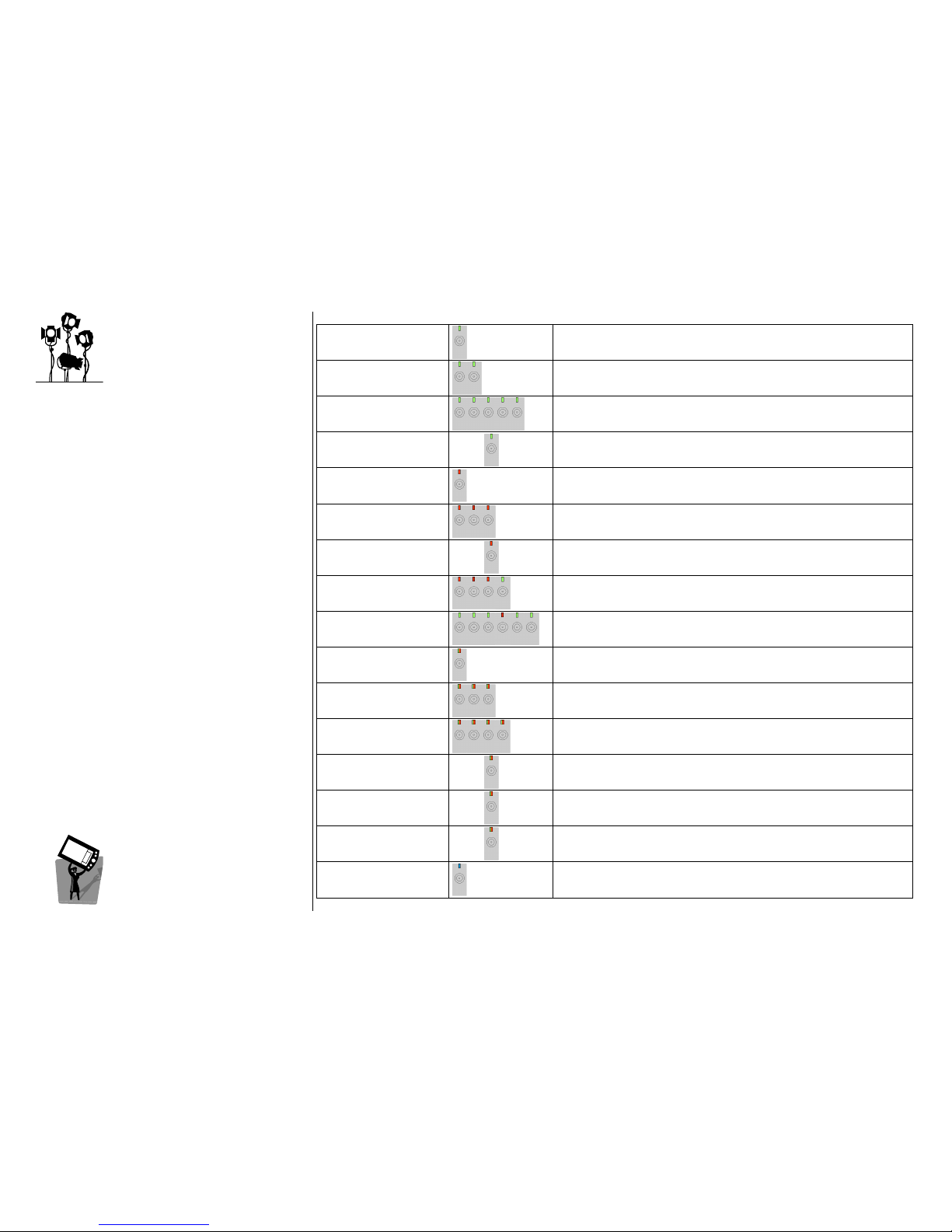
1 GREEN
Door already in office or danger status
2 GREEN
Function executed successfully
(block, synchronization, office on, reset, etc.)
5 GREEN
Opening enabled
10 GREEN 10x
Lock not initialized
1 RED
Reading error. If repeated every 3 seconds: Privacy active
Privacy activePrivacy active
Privacy active
(also on Cisa logo near the privacy button on internal side)
3 RED
Card not valid (expired, invalidated by a new one, etc.)
6 RED 6x
Device not synchronized
3 RED + 1
GREEN
Card temporarily not valid
(blocked, out of the working hours, guest in privacy)
3 GREEN + 1RED +
2 GREEN
Initialization OK
1 RED&GREEN
Operation in progress (followed by 2 green or 2 red
depending on the result)
3 RED&GREEN
Low battery (Staff cards only)
4 RED&GREEN
Function of card in sequence executed successfully
10 RED&GREEN 10x
Delayed close (Staff cards only, if DPR is enabled)
12 RED&GREEN 12x
End battery
20 RED&GREEN
20x
Tampering: DPR circuit disconnected (Staff cards only)
1 BLUE
Communication with HHI via mouse in progress
Page 28
ESIGNO_SYSTEM_USER_MANUAL_101.DOCX 28/71
Z
ZZ
ZONES
ONES ONES
ONES
((((1111))))
AAAACCESS
CCESS CCESS
CCESS T
TT
TARGETS
ARGETSARGETS
ARGETS
SSSS
TATIC
TATIC TATIC
TATIC
ZZZZ
ONES
ONESONES
ONES
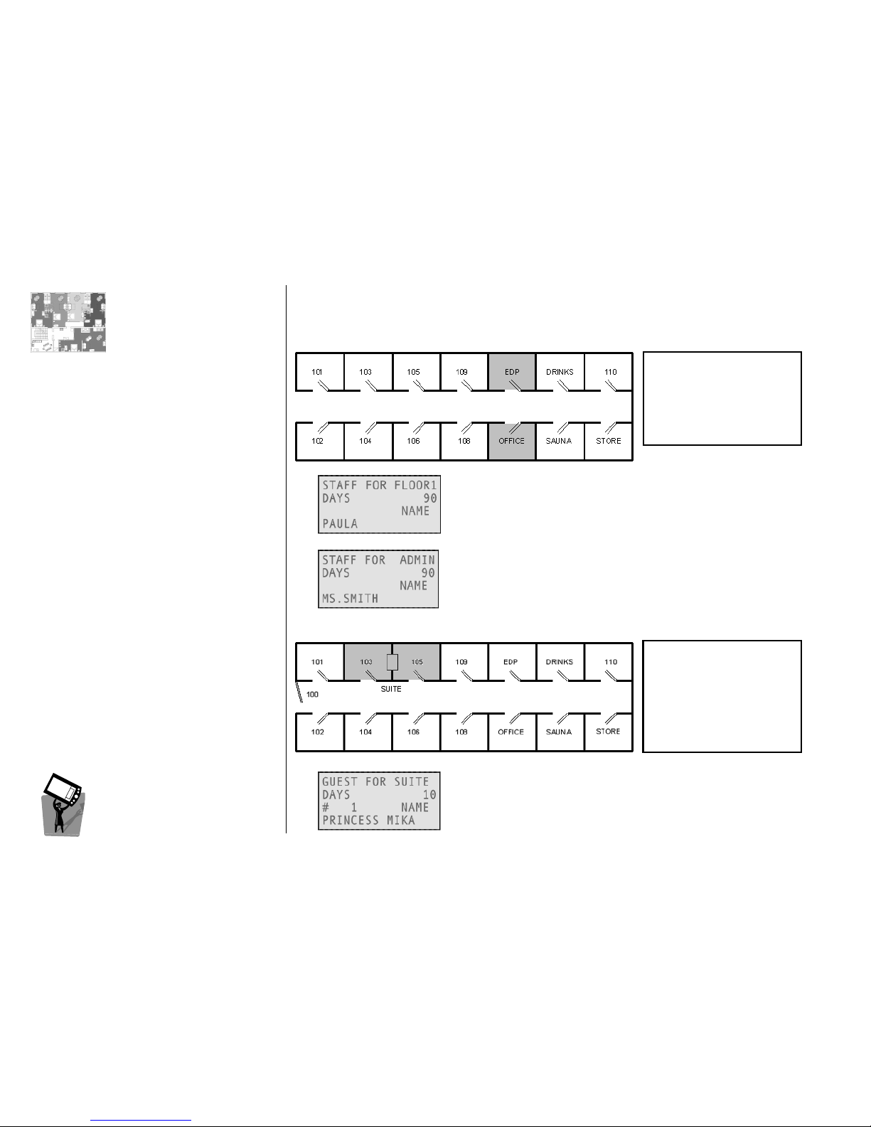
Groups of locks defined during system configuration.
Example 1
Example 1Example 1
Example 1
A zone can be an input for any card: with this card a staff member will
open all the locks in the FLOOR1 zone (room 101 to 110).
With this card, a staff member will open the locks into the ADMIN
zone i.e. rooms OFFICE and EDP. There are two additional features:
• Override Privacy: card opens also if the colleagues are closed inside;
• Office Function: inserted twice, card will put the lock in office mode.
Example 2
Example 2Example 2
Example 2
With this card, a guest will open the SUITE zone (rooms 103 and 105);
alternatively one card can be issued only for 103 and one card only
for 105. Remember that a latest card always invalidates an earlier one.
FLOOR1 101
FLOOR1 101 FLOOR1 101
FLOOR1 101 ---- 110
110110
110
FLOOR2 201 - 209
FLOOR3 301 - 309
MASTER All rooms
ADMIN OFFICE + EDP
ADMIN OFFICE + EDPADMIN OFFICE + EDP
ADMIN OFFICE + EDP
GUESTS All guests
rooms
FLOOR1 101 - 110
MASTER All rooms
ADMIN OFFICE + EDP
GUESTS All guests rooms
SUITE 103 + 105
SUITE 103 + 105SUITE 103 + 105
SUITE 103 + 105
MINBAR Guest rooms +
DRINKS
Page 29
ESIGNO_SYSTEM_USER_MANUAL_101.DOCX 29/71
ZZZZONES
ONES ONES
ONES
(
(((2222))))
AAAACCESS
CCESS CCESS
CCESS T
TT
TARGETS
ARGETSARGETS
ARGETS
DDDD
YNAMIC
YNAMIC YNAMIC
YNAMIC
ZZZZ
ONES
ONES ONES
ONES
((((
FFFFOR
OR OR
OR
GGGG
UESTS
UESTSUESTS
UESTS
))))
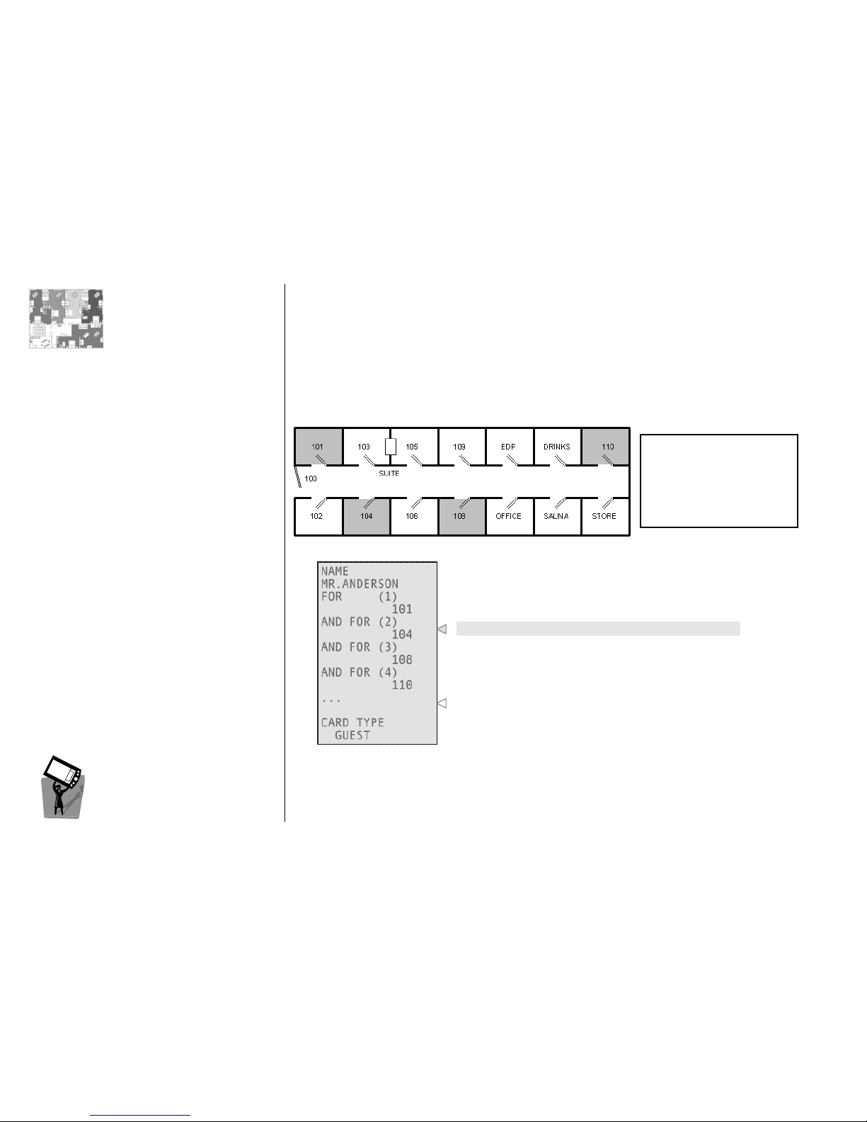
Groups of locks defined, for guests only, upon need at the check-in time.
Example
ExampleExample
Example
Up to 4 completely independent doors can be selected.
All the other information about the card.
FLOOR1 101 - 110
FLOOR2 201 - 209
FLOOR3 301 - 309
MASTER All rooms
ADMIN OFFICE + EDP
GUESTS All guest rooms
Page 30
ESIGNO_SYSTEM_USER_MANUAL_101.DOCX 30/71
CCCCATEGORIES
ATEGORIESATEGORIES
ATEGORIES
TIP
TIPTIP
TIP
Categories can be created:
• from the Category Manager Menu of the
eSIGNO Mobile in encoder mode;
• from the appropriate form in the Smart
Software.
CCCCATEGORIES
ATEGORIESATEGORIES
ATEGORIES
Categories
CategoriesCategories
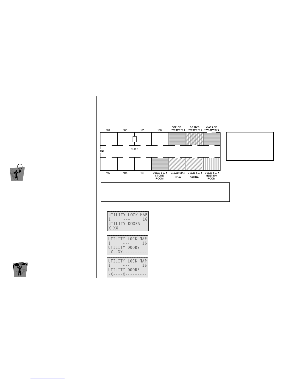
Categories are groups of utility doors: it is possible to create several categories according to hotel
management’s different needs.
After having defined a utility pattern, it is possible to use it more times for different cards; in this way,
the receptionist doesn't need to redefine the utility lock map each time he/she issues a new card.
Example
ExampleExample
Example
HOTEL Category
HOTEL CategoryHOTEL Category
HOTEL Category
Used by hotel staff members, includes Office, Garage and Store Room.
TOUR(ist) Category
TOUR(ist) CategoryTOUR(ist) Category
TOUR(ist) Category
It can be used for all the guests who should have access to the hotel
extra services (in this case Drinks, UVA and Sauna).
BUSIN(ess) Category
BUSIN(ess) CategoryBUSIN(ess) Category
BUSIN(ess) Category
This category allows access to business-related services (in this case
Drinks and Meeting Room).
1 keyplan
3 kinds of card holders:
• Hotel staff member
• Tourist
• Business man
UTILITIES ID MAP
UTILITIES ID MAPUTILITIES ID MAP
UTILITIES ID MAP
1 2 3 4 5 6 7
OFFICE DRINKS GARAGE STORE UVA SAUNA MEETING
Page 31
ESIGNO_SYSTEM_USER_MANUAL_101.DOCX 31/71
EEEENCODER
NCODER NCODER
NCODER M
MM
MAIN
AIN AIN
AIN M
MM
MENU
ENUENU
ENU
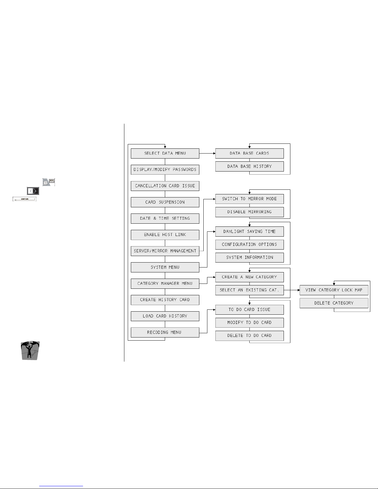
This special menu allows several functions to be
performed, depending on operator hierarchy.
To access this menu, once logged in Encoder
Mode, press , navigate through its voices
with and confirm your choice with
.
EEEENCODER
NCODERNCODER
NCODER M
MM
MODE
ODEODE
ODE
MMMMENU
ENUENU
ENU
Page 32
ESIGNO_SYSTEM_USER_MANUAL_101.DOCX 32/71
S
SS
SELECT
ELECTELECT
ELECT D
DD
DAT
ATAT
ATAAAA M
MM
MENU
ENUENU
ENU
TIP
TIPTIP
TIP
From the Input
InputInput
Input FFFForm
ormorm
orm, search is possible only on
the active cards
active cardsactive cards
active cards (cards that are not expired nor
future).
EEEENCODER
NCODER NCODER
NCODER M
MM
MODE
ODE ODE
ODE
MMMMENU
ENUENU
ENU
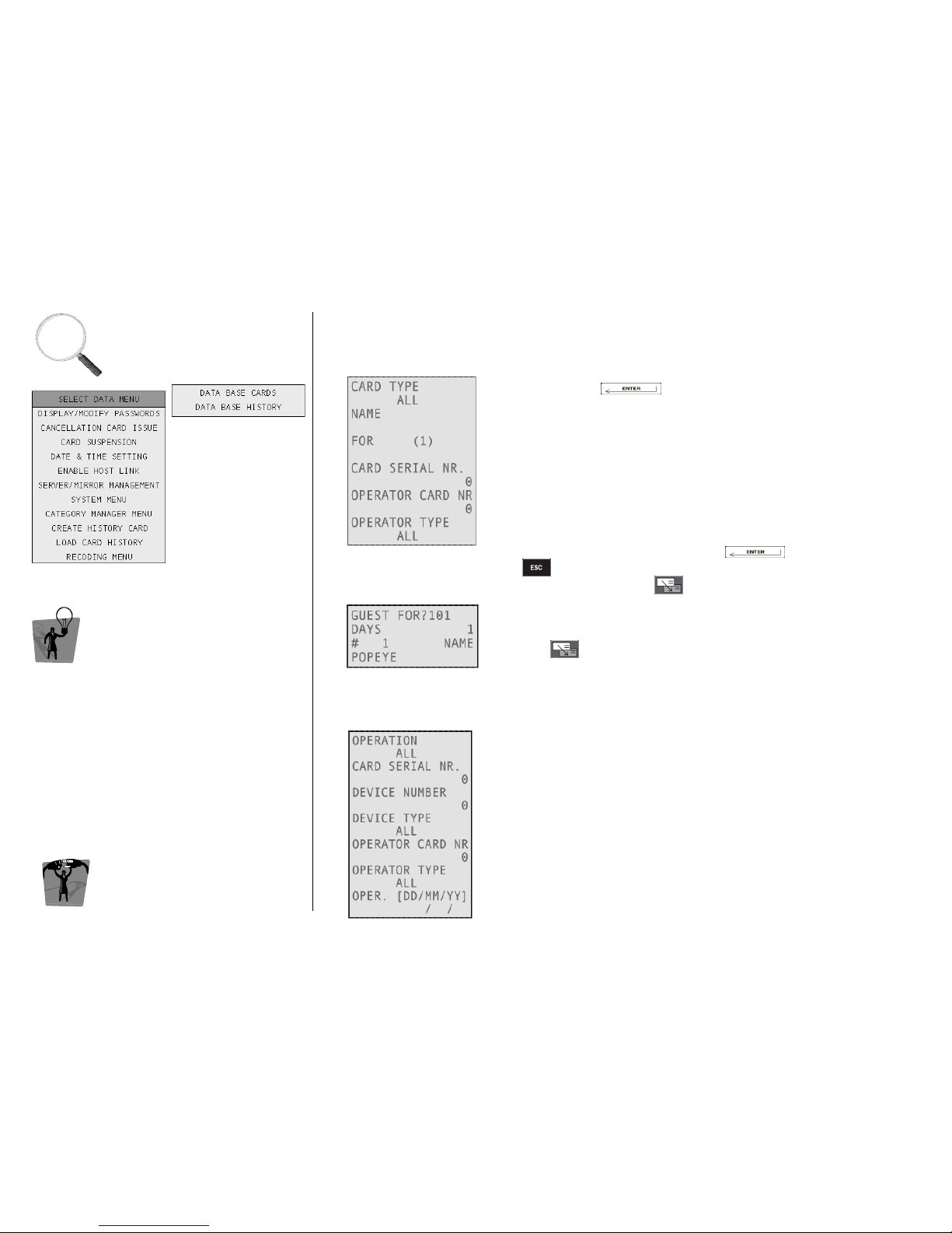
SEARCHING FOR CARDS
SEARCHING FOR CARDSSEARCHING FOR CARDS
SEARCHING FOR CARDS
This kind of search is possible from the Select Data Menu
Select Data MenuSelect Data Menu
Select Data Menu or from the Input
InputInput
Input FFFForm
ormorm
orm.
AAAA
Enter in the Select Data Menu
Select Data MenuSelect Data Menu
Select Data Menu, then into the Data Base Cards
Data Base CardsData Base Cards
Data Base Cards, each
time by pressing . The search criteria for cards are:
• Card Type: search for a single type (e.g. guest) or between all types;
• Name: it’s also possible to search a single part of the name
(e.g. typing AR, the system will find ARnold, mARia and so on);
• For: to search the cards issued for a room or a zone;
• Card Serial Number: card with a specified number of issuing;
• Operator Card Nr: cards issued by the specified Operator Card;
• Operator Type: cards issued by Encoder, PMS-Host or both (ALL).
The search function can have more than one criterion at a time,
considering them in logical AND. Press to start the search
or to quit. If more than one card fit the criteria, the list of results
can be scrolled by pressing .
BBBB
Search is also possible from the Input Form
Input FormInput Form
Input Form only by room number:
• Enter desired room number;
• Press to start search. If a card is found, a “?” near the room
number indicates that you are in search mode.
SEARCHING FOR HISTORY OF OPERATIONS
SEARCHING FOR HISTORY OF OPERATIONSSEARCHING FOR HISTORY OF OPERATIONS
SEARCHING FOR HISTORY OF OPERATIONS
This kind of search is possible from the Data Base
Data Base Data Base
Data Base History
HistoryHistory
History menu only.
The search criteria for history of operations are:
• Operation Type: search for operations depending on their kind
(e.g. login, logout, issue or cancellation of different kinds of cards,
maintenance);
• Device Type and Number: search for operations done by a
specified kind of devices (server, mirror, client, HHI, special lock or
all) or by a single device identified by a specified ID number;
• Operator Type and Number: search for operations done by
Encoder, PMS-Host or both (ALL), or by a specified operator card;
• Operations sorted by date.
Page 33
ESIGNO_SYSTEM_USER_MANUAL_101.DOCX 33/71
DDDDISPLAY
ISPLAY ISPLAY
ISPLAY /
//
/
M
MM
MODIFY
ODIFYODIFY
ODIFY
PPPPASSWORDS
ASSWORDSASSWORDS
ASSWORDS
CCCCANCELLATION
ANCELLATIONANCELLATION
ANCELLATION
CCCCARD
ARD ARD
ARD I
II
ISSUE
SSUESSUE
SSUE
EEEENCODER
NCODER NCODER
NCODER M
MM
MODE
ODE ODE
ODE
MMMMENU
ENUENU
ENU
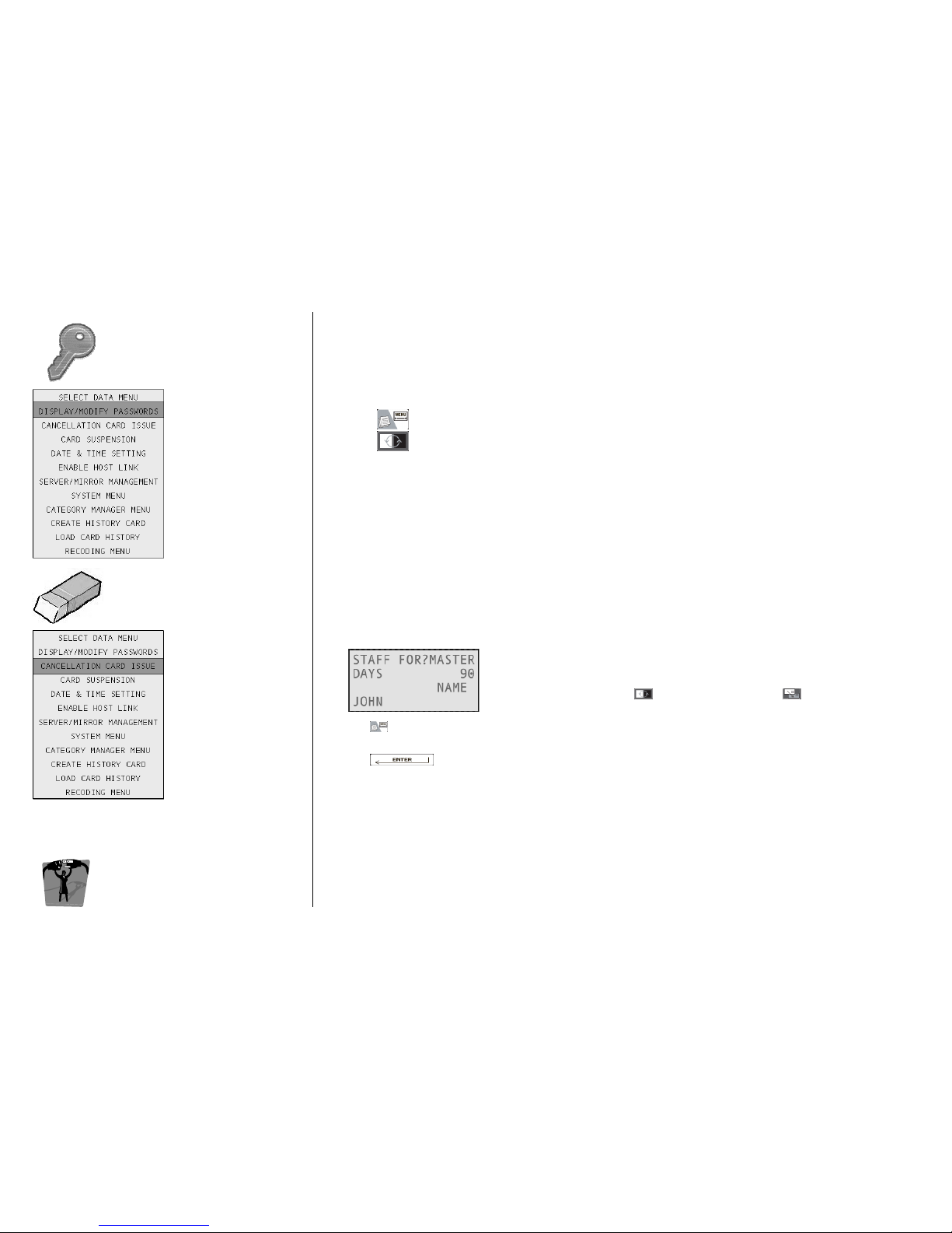
MODIFY PASSWORDS
MODIFY PASSWORDSMODIFY PASSWORDS
MODIFY PASSWORDS
Enables the users to change their own password, or the system manager to change the password
of other operators. Steps are as follows:
• from the Input Form approach your own operator card or search for an operator;
• press ;
• press and select Display / Modify Passwords (the card in zoom mode will be displayed);
change the password.
On each lock, there is a black list where it is possible to memorize a certain number of guest, staff,
operator or emergency cards, so that they are then barred from entering the room.
CREATING A
CREATING A CREATING A
CREATING A CANCELLATION
CANCELLATION CANCELLATION
CANCELLATION CARD
CARDCARD
CARD
• Approach the card to be inserted into the black list to the tag
reader; alternatively, you can search for that card from the Input
Form: navigate with to Staff For, then press until you
visualize the card you want to cancel;
•
press ;
• select Cancellation Card Issue (the card in zoom mode will be displayed);
• press to confirm;
• write the Cancellation Card by approaching a virgin card to the encoder;
• keep it close to all the locks: the desired card has now been inserted into the black list.
BLACK LIST CAPACITY
BLACK LIST CAPACITYBLACK LIST CAPACITY
BLACK LIST CAPACITY:
• Normal lock: up to 150 staff or operator cards (guest cards are disabled by passing a new one);
• Common lock: up to 150 staff, operator or guest cards.
Note
NoteNote
Note: on wireless locks, it is possible to update the black list by remote.
Page 34
ESIGNO_SYSTEM_USER_MANUAL_101.DOCX 34/71
CCCCARD
ARD ARD
ARD S
SS
SUSPENSION
USPENSIONUSPENSION
USPENSION
DDDDATE
ATE ATE
ATE &
&&
&
T
TT
TIME
IMEIME
IME
SSSSETTINGS
ETTINGSETTINGS
ETTINGS
EEEENCODER
NCODER NCODER
NCODER M
MM
MODE
ODE ODE
ODE
MMMMENU
ENUENU
ENU
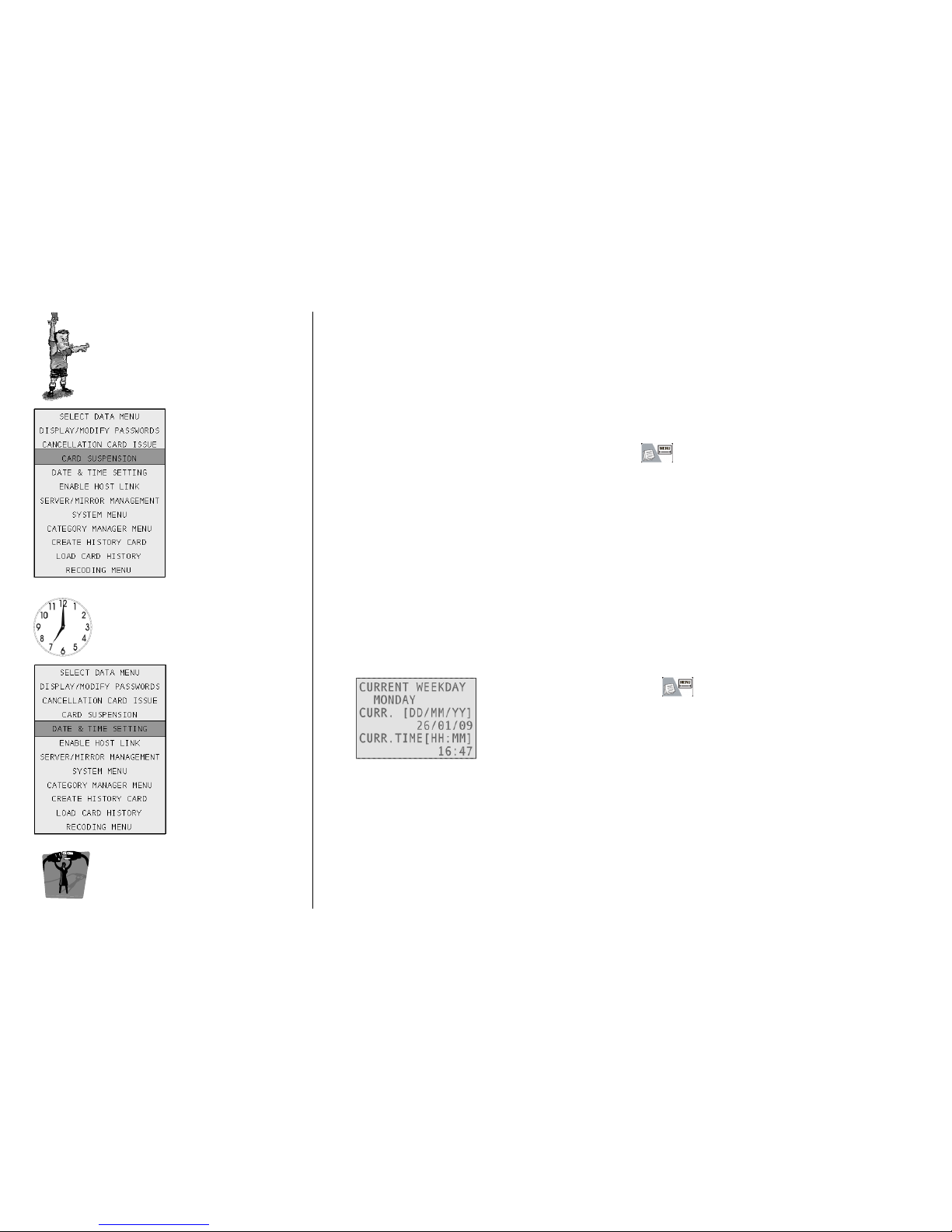
This function, active only for cards for which has been set the validation, permits the suspension of the
card’s validity for a certain period of time.
Put upon the tag reader a card with validation and press , then select Card Suspension.
To set Date and Time, press , then select Date & Time Settings.
In this frame you can set the current date and time; if you change the
current date, the system automatically updates the weekday (it is not
possible to directly modify the weekday).
Whenever you modify the system date and time, all locks must be
synchronized.
Page 35
ESIGNO_SYSTEM_USER_MANUAL_101.DOCX 35/71
EEEENABLE
NABLENABLE
NABLE
HHHHOST
OST OST
OST L
LL
LINK
INKINK
INK
EEEENCODER
NCODER NCODER
NCODER M
MM
MODE
ODE ODE
ODE
MMMMENU
ENUENU
ENU
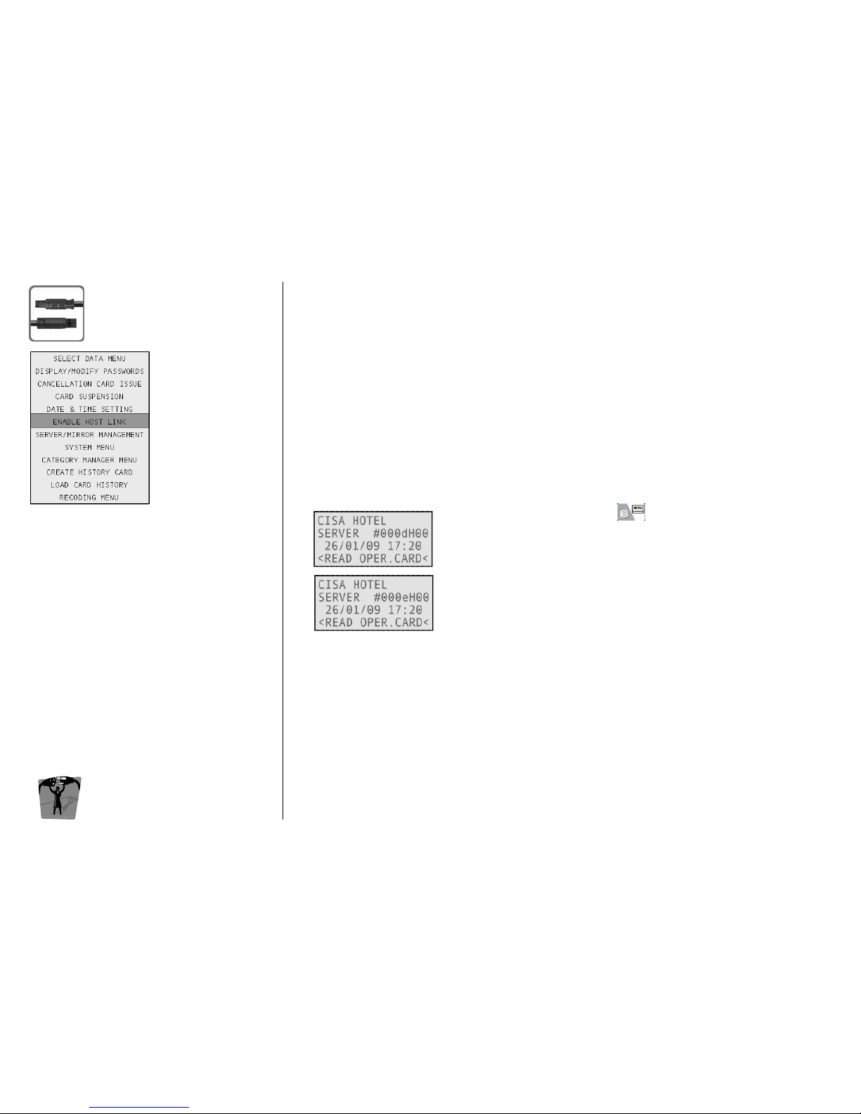
This function allows to enable/disable the PMS communication.
WHY TO INTERFACE WITH PMS
WHY TO INTERFACE WITH PMSWHY TO INTERFACE WITH PMS
WHY TO INTERFACE WITH PMS
The interface is able to connect the encoding station with the Hotel
Management System Computer allowing the issuing of guest cards or
duplicates of issued guest cards.
The advantage of an interface system is to avoid double check-in data
input, in order to achieve great efficiency in operations and giving no
risk of data incongruence between the two systems.
HOW TO INTERFACE WITH PMS
HOW TO INTERFACE WITH PMSHOW TO INTERFACE WITH PMS
HOW TO INTERFACE WITH PMS
The connection between the interface and the PMS is standard:
Serial RS232
Serial RS232Serial RS232
Serial RS232
PMS is directly connected to the ESIGNO Mobile by a serial cable
without any interface controller; the link is enabled/disabled selecting
Enable Host Link after pressing .
Whether the connection is enabled or not, it is visible on the screen
when the encoder is in standby:
• #000dH00: link disabled;
• #000eH00: link enabled.
THE COMMUNICATION PROTOCOL
THE COMMUNICATION PROTOCOLTHE COMMUNICATION PROTOCOL
THE COMMUNICATION PROTOCOL
The standard CISA protocol describes the messages that the Hotel
Management System Computer should send for making a card and
the response that CISA sends back. The basic data sent by PMS are:
• room number;
• guest name;
• date and time for the check-in;
• date and time for the check-out;
• number of copies to issue.
To issue cards from the PMS, the encoder must be in an idle state.
Page 36
ESIGNO_SYSTEM_USER_MANUAL_101.DOCX 36/71
SSSSERVER
ERVER ERVER
ERVER /
//
/
M
MM
MIRROR
IRRORIRROR
IRROR
MMMMANAGEMENT
ANAGEMENTANAGEMENT
ANAGEMENT
TIP
TIPTIP
TIP
In case of Mirror device malfunction, it is possible
to disable it, and re-enable it in a second
moment, using the Enable Mirroring function.
EEEENCODER
NCODER NCODER
NCODER M
MM
MODE
ODE ODE
ODE
MMMMENU
ENUENU
ENU
The Mirror is a device whose memory and functionality are exactly
identical to Server’s: therefore, with Mirror device, it is possible to do
the same operations you can do with Server.
During the creation of the plant you can choose to have one or more
Mirror devices: this is useful if you have more than one place where
you issue and write cards (for example if you have more than one
reception in the hotel).
SWITCH TO MIRROR
SWITCH TO MIRROR SWITCH TO MIRROR
SWITCH TO MIRROR / SERVER
/ SERVER / SERVER
/ SERVER MODE
MODEMODE
MODE
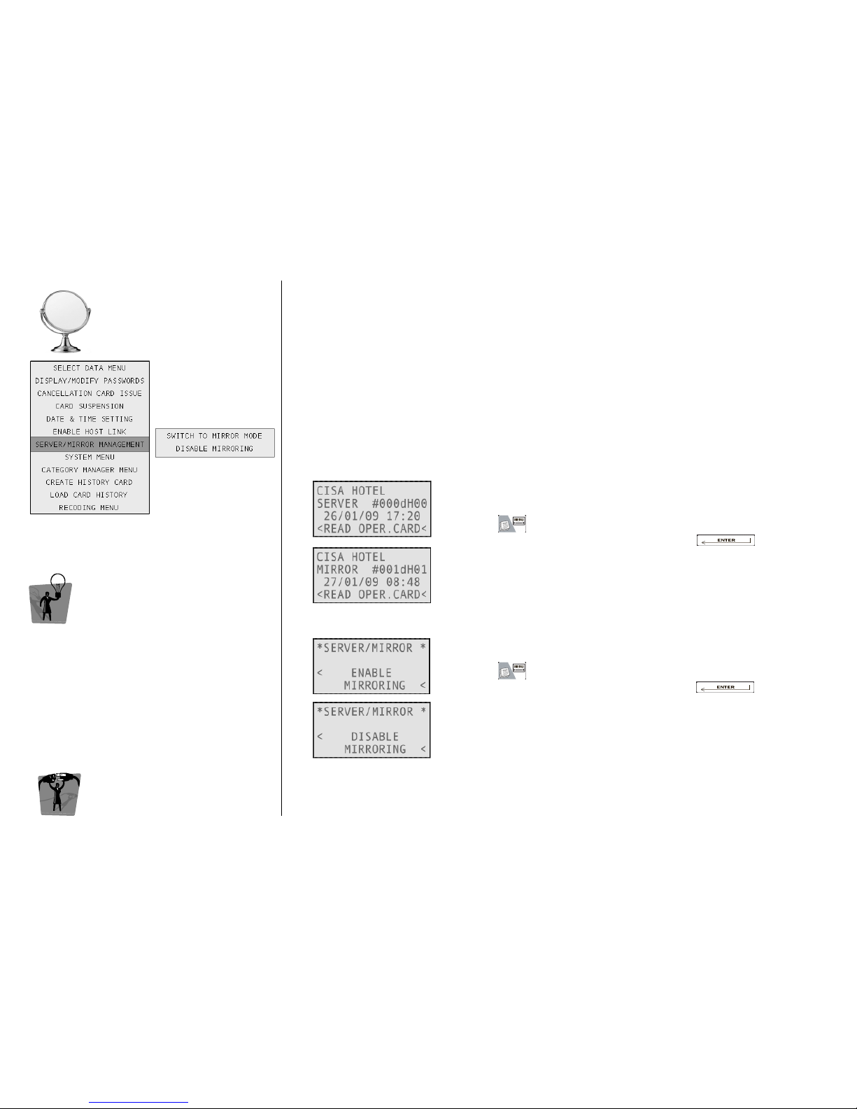
The ESIGNO Mobile can work in both Server and Mirror mode.
To switch the encoder from one mode to the other:
• press ;
• select Server/Mirror Management by pressing ;
• select Switch to Mirror (Server) Mode. .
ENABLE MIRRORING MODE
ENABLE MIRRORING MODEENABLE MIRRORING MODE
ENABLE MIRRORING MODE
To enable/disable mirroring mode:
• press ;
• select Server/Mirror Management by pressing ;
• select Enable (Disable) Mirroring.
When a plant contains a Mirror device, mirroring is automatically
enabled in the Server.
Page 37
ESIGNO_SYSTEM_USER_MANUAL_101.DOCX 37/71
SSSSYSTEM
YSTEMYSTEM
YSTEM M
MM
MENU
ENUENU
ENU
((((1111))))
TIP
TIPTIP
TIP
For Italy and most of the EEC country, the time
change usually happens on the last Sunday of
March from 2.00 to 3.00 am and on the last
Sunday of October from 3.00 to 2.00 am.
EEEENCODER
NCODER NCODER
NCODER M
MM
MODE
ODE ODE
ODE
MMMMENU
ENUENU
ENU
DDDD
AYLIGHT
AYLIGHT AYLIGHT
AYLIGHT
SSSS
AVING
AVING AVING
AVING
TTTT
IME
IMEIME
IME
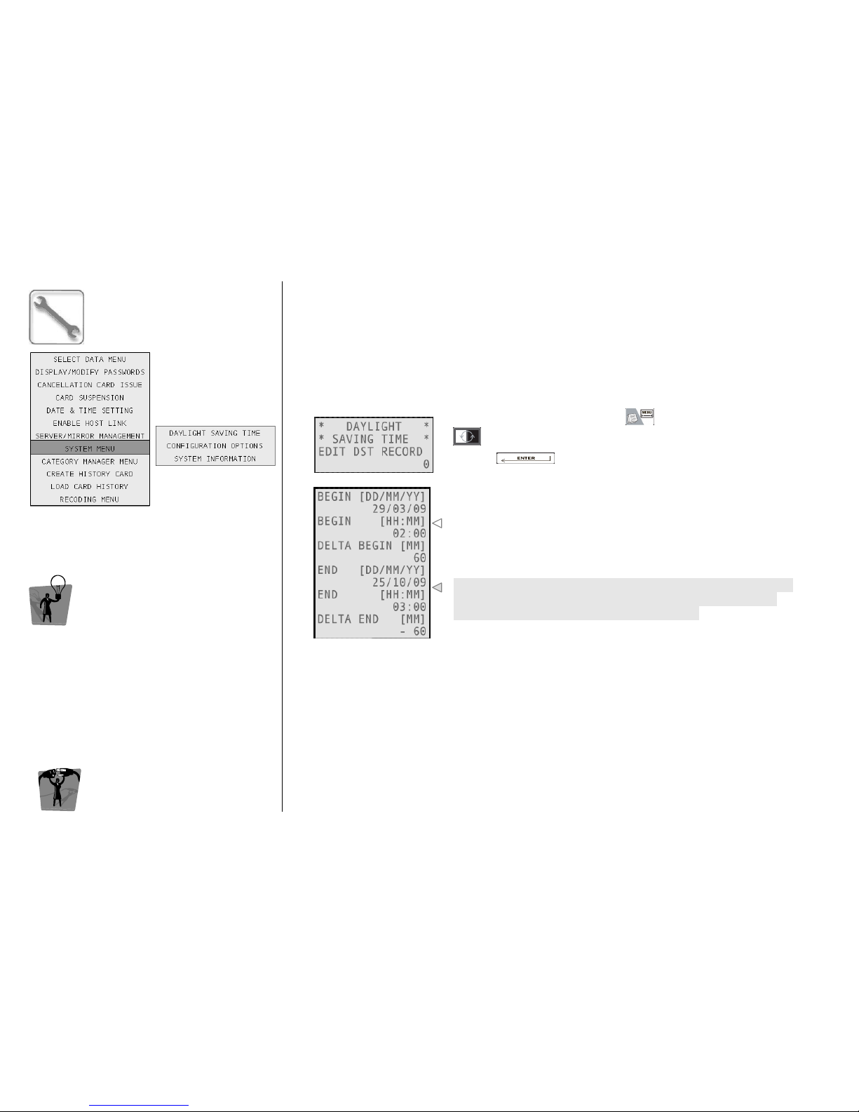
Locks and encoding station work with the actual time; regarding daylight saving time, they are able to
automatically change the time for 10 years in advance, provided they have the proper DST
information.
Therefore, the encoder contains 10 records, one for each year to come. It is possible to edit any record
from 0 to 9 (10 years); once a record is expired, it will be automatically deleted and the table will be
shifted from top to bottom.
1111
To change the DST settings, press
, navigate into the menu with
and select System Menu and then Daylight Saving Time by
pressing .
Choose the record to be modified by typing the correspondent ID.
2222
Set the date and time of the beginning of the DST, then the time shift
which has to occur (a positive number n represents an addiction of n
minutes)
Set the date and time of the end of the DST, then the time shift that
has to occur (a negative number n represents a subtraction of n
minutes). To insert this value, type n and then “-“.
NOTES
• If the encoding station does not have DST tables, you will see a warning message when logging in
to the encoding station.
• If the lock is out of the DST tables, it introduces a delta of an hour in advance, so that the cards will
be valid 1 hour in advance remaining in solar time.
• In case your country does not have DST, there will be only one record, with begin and end in
2051, avoiding the lock to introduce deltas.
Page 38
ESIGNO_SYSTEM_USER_MANUAL_101.DOCX 38/71
SSSSYSTEM
YSTEM YSTEM
YSTEM M
MM
MENU
ENUENU
ENU
((((2222))))
TIP
TIPTIP
TIP
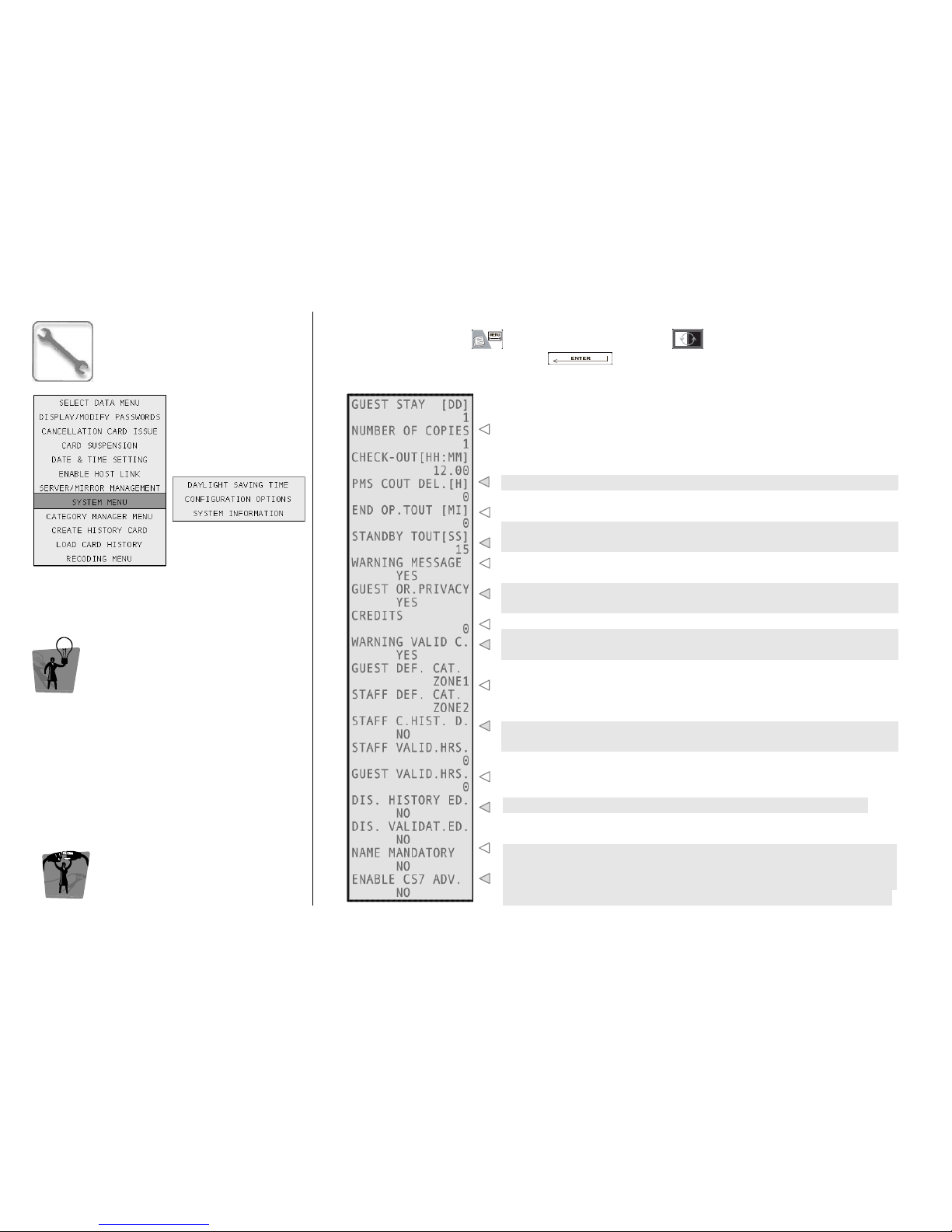
The Configuration Options menu lets you
modify the defaults parameters for cards issuing.
EEEENCODER
NCODER NCODER
NCODER M
MM
MODE
ODE ODE
ODE
MMMMENU
ENUENU
ENU
CCCC
ONFIGURATION
ONFIGURATION ONFIGURATION
ONFIGURATION
OOOO
PTIONS
PTIONSPTIONS
PTIONS
To access this menu, press , navigate into the menu with and select System Menu and
then Configuration Options by pressing .
These are the default values for guest cards issue: guest stay duration,
number of copies to be issued and the check-out time.
Delay added to end of validity time sent by the PMS to the encoder.
After being idle for this time period, the system goes into standby
mode: it’s now necessary to login with operator card (0 = no timeout).
After being idle for this time period, the system ends the operation
(e.g. pw input) and returns to the card issuing menu (0 = no timeout).
Enable this warning message to be informed that the room you are
creating a card for is busy.
Setting this value, you can decide whether a newly issued guest card
has the Override Privacy function or not.
This is the number of credits awarded by default to each guest card.
Enable this warning message to be informed that the card you are
creating has already been written and is still valid.
These are the category of utility doors you want to allow access to
by
default to all guest and staff cards, respectively.
After enabling this field, the staff cards will have history on board by
default.
Type here validation hours for staff and guest cards repectively.
Disable history and validation options editing when issuing cards.
Enabling this field, it will be mandatory to type the user’s name in the
moment the card is issued.
Enabling this field, it is possible to use the CS7 card (which is faster to
read and has more memory, compared to a CS5 card) additional
features, like the extended keyplan. This feature works only if the
firmware installed on the locks is up to date with that on the encoder.
Page 39
ESIGNO_SYSTEM_USER_MANUAL_101.DOCX 39/71
SSSSYSTEM
YSTEM YSTEM
YSTEM M
MM
MENU
ENUENU
ENU
((((3333))))
TIP
TIPTIP
TIP
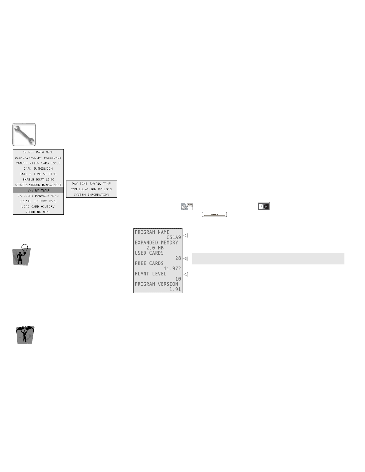
The System Information menu gives you
information about the encoding station
software version, memory size and cards
database occupation.
EEEENCODER
NCODER NCODER
NCODER M
MM
MODE
ODE ODE
ODE
MMMMENU
ENUENU
ENU
SSSS
YSTEM
YSTEM YSTEM
YSTEM
IIII
NFORMATION
NFORMATIONNFORMATION
NFORMATION
To access this menu, press , navigate into the menu with and select System Menu and
then System Information by pressing .
Here you can see the name of the firmware installed on your
encoder; at the bottom, the program version is displayed.
This is the balance of used and free to use cards for your plant
(depends on the expanded memory of the encoder).
This value depends on the technology the plant is based on.
Page 40
ESIGNO_SYSTEM_USER_MANUAL_101.DOCX 40/71
CCCCATEGORY
ATEGORY ATEGORY
ATEGORY M
MM
MANAGER
ANAGERANAGER
ANAGER
MMMMENU
ENUENU
ENU
(1)
(1)(1)
(1)
TIP
TIPTIP
TIP
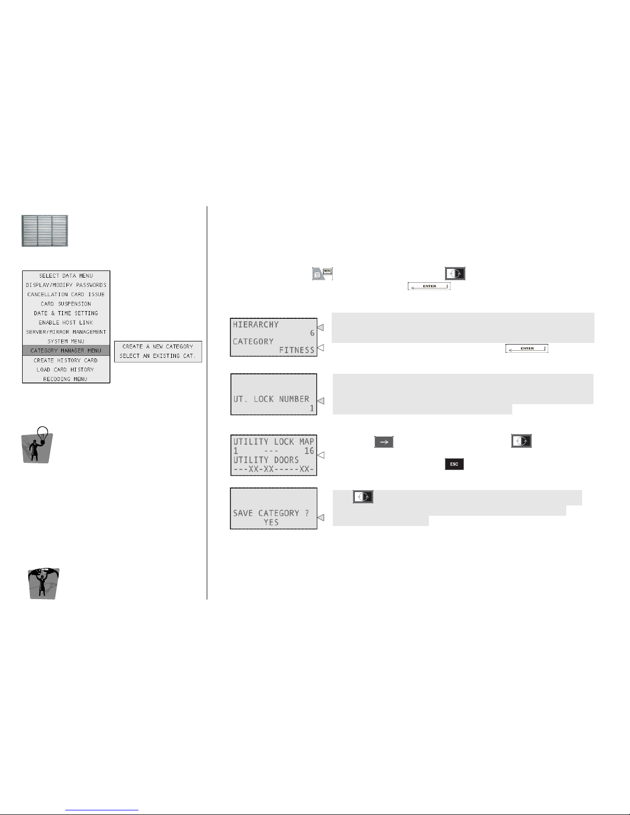
This menu allows the creation of new groups of
utility doors called categories
categoriescategories
categories.
EEEENCODER
NCODER NCODER
NCODER M
MM
MODE
ODE ODE
ODE
MMMMENU
ENUENU
ENU
CREATE A NEW CATEGORY
CREATE A NEW CATEGORYCREATE A NEW CATEGORY
CREATE A NEW CATEGORY
To access this menu, press , navigate into the menu with and select Category Manager
Menu and then Create a New Category by pressing .
1111
Type here the minimum hierarchic level an operator must have to be
allowed to use this category; this parameter can be used to create
protected categories that only high hierarchy operators can use.
Type here the name of the category and press .
2222
Here you have to type the number of the utility you want to manage,
considering that the system will visualize utilities in groups of 16 (e.g.
typing a random number between 1 and 16, you can manage all the
first 16 utilities, then 17 ÷ 32, 33 ÷ 48 and so on).
3333
Move with to select from the utility list and to select (X) or
unselect (-) the door. After having completed the utility pattern
according to your needs press .
4444
With select whether you want to save the category you have
just created or not. Now you will automatically step back to the
Category Manager menu.
Page 41
ESIGNO_SYSTEM_USER_MANUAL_101.DOCX 41/71
CCCCATEGORY
ATEGORY ATEGORY
ATEGORY M
MM
MANAGER
ANAGERANAGER
ANAGER
MMMMENU
ENU ENU
ENU
((((2222))))
TIP
TIPTIP
TIP
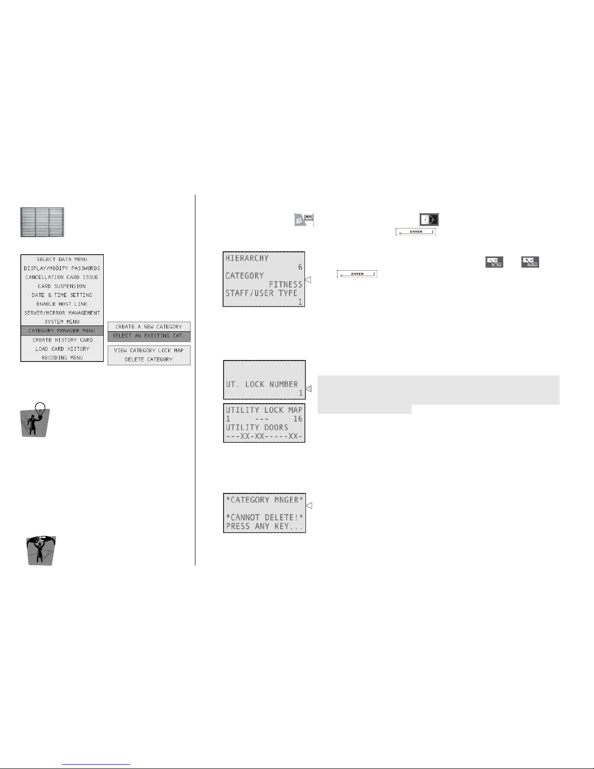
From this menu it is possible to choose an
existing category and delete it, print it or view its
utility lock map.
EEEENCODER
NCODER NCODER
NCODER M
MM
MODE
ODE ODE
ODE
MMMMENU
ENUENU
ENU
SELECT AN EXISTING CATEGORY
SELECT AN EXISTING CATEGORYSELECT AN EXISTING CATEGORY
SELECT AN EXISTING CATEGORY
To access this menu, press , navigate into the menu with and select Category Manager
Menu and then Select an Existing Category by pressing .
1111
Select the category you want to manage, using and , then
press .
Now choose one of the following functions: View Category Lock
Map or Delete Category.
VIEW
VIEW VIEW
VIEW CATEGORY
CATEGORY CATEGORY
CATEGORY LOCK MAP
LOCK MAPLOCK MAP
LOCK MAP
The system shows the utility pattern of the selected category. This pattern cannot be edited after
creation.
2a
2a2a
2a
Type here the number of the utility you want to see, considering that
the system will visualize utilities in groups of 16 (e.g. typing a random
number between 1 and 16, you can see all the first 16 utilities, then
17 - 32, 33 - 48 and so on).
DELETE CATEGORY
DELETE CATEGORYDELETE CATEGORY
DELETE CATEGORY
The system cancels the selected category.
2b
2b2b
2b
This function can be used only:
• if no active card is using the selected category;
• if the category has not been defined as default category for guest
or staff cards.
Otherwise, this message will be prompted.
Page 42
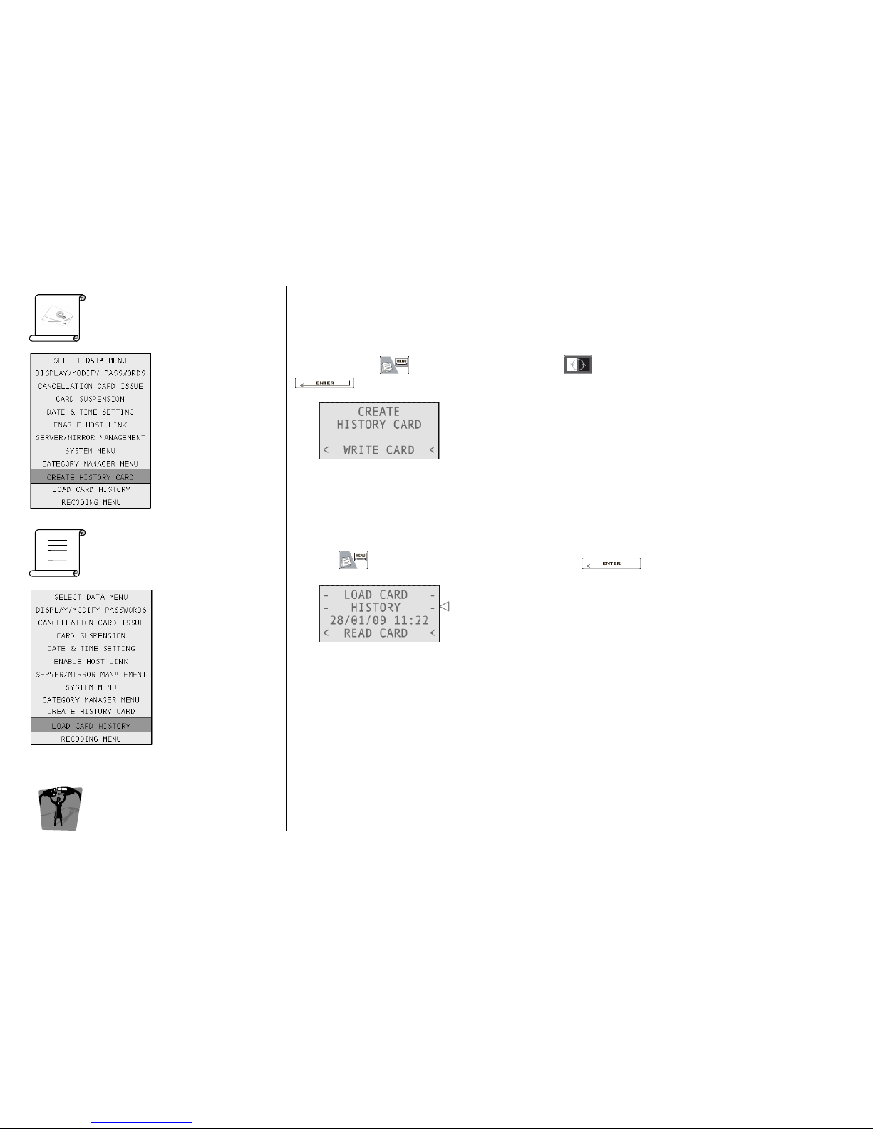
ESIGNO_SYSTEM_USER_MANUAL_101.DOCX 42/71
CCCCREATE
REATEREATE
REATE
HHHHISTORY
ISTORY ISTORY
ISTORY C
CC
CARD
ARDARD
ARD
LLLLOAD
OADOAD
OAD
CCCCARD
ARD ARD
ARD H
HH
HISTORY
ISTORYISTORY
ISTORY
EEEENCODER
NCODER NCODER
NCODER M
MM
MODE
ODE ODE
ODE
MMMMENU
ENUENU
ENU
It’s possible to create a special card that, once presented to a lock, can download its whole history.
To do this, press , navigate into the menu with and select Create History Card by pressing
. The encoder will ask you to present a card to be written.
Once the history card has been written, you can present it to the reader of the lock: in this way history
data will be written on the card. When this operation is completed, the lock will simultaneously display
red and green lights.
In order to visualize data, you have to:
• press and select Load Card History by pressing ;
The encoder will ask you the card to be read.
• present the card with history data on board to the encoder;
if the card has some data stored on its memory, they will be transferred into the encoder and
shown on the display;
if the card contains no data, an error message will be shown.
Note
NoteNote
Notessss:
: :
:
• a history card can be used just once; to use it again, you have to create a new one.
• on wireless locks, it is possible to perform this operation by remote.
Page 43
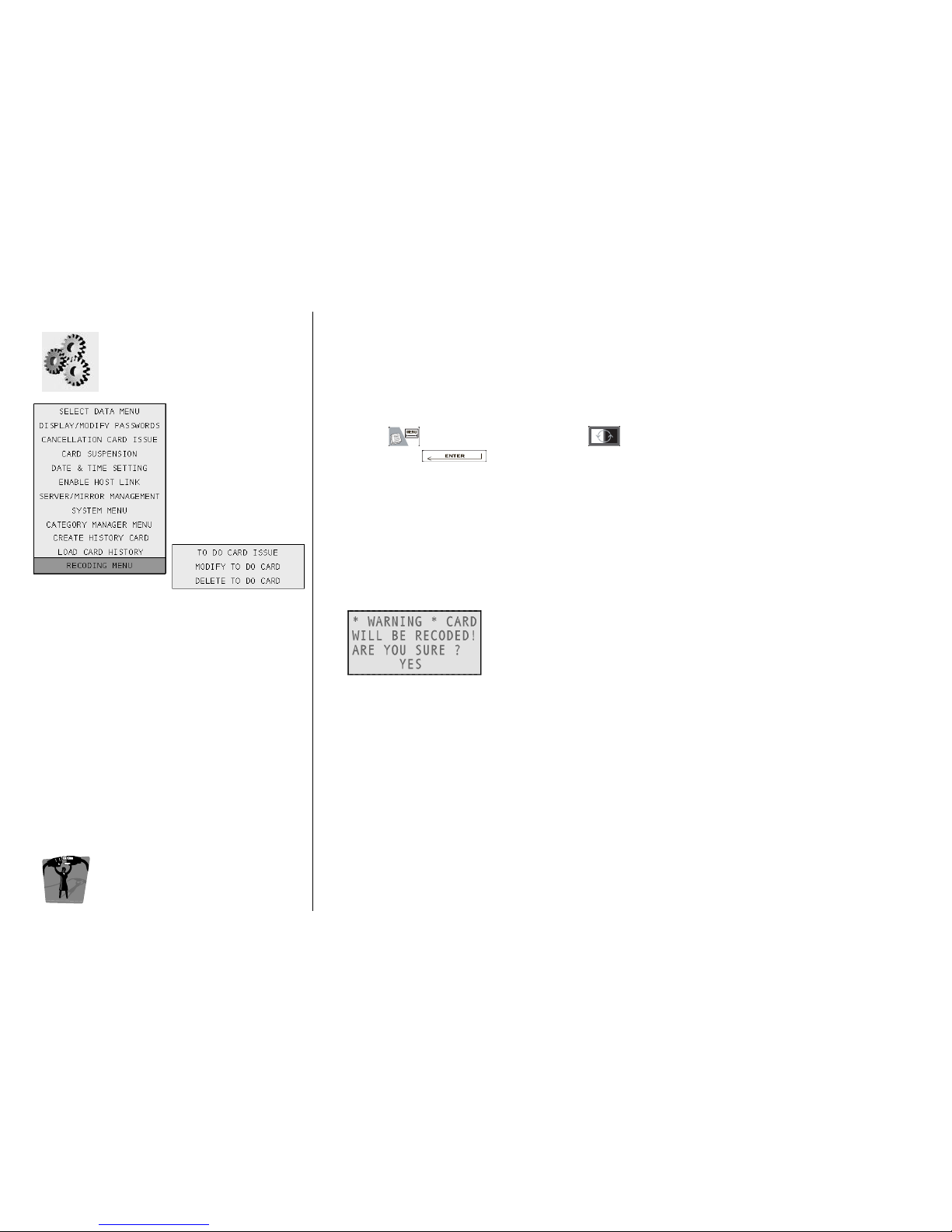
ESIGNO_SYSTEM_USER_MANUAL_101.DOCX 43/71
RRRRECODING
ECODINGECODING
ECODING
MMMMENU
ENUENU
ENU
EEEENCODER
NCODER NCODER
NCODER M
MM
MODE
ODE ODE
ODE
MMMMENU
ENUENU
ENU
The recoding function
recoding functionrecoding function
recoding function consists in the possibility of changing parameters of already issued staff or user
cards. This function is not active by default: in fact, the recoding menu is accessible only if during the
initialization of the plant it has been enabled.
It is possible to recode a staff or user card in two different ways:
• searching for a card in the cards database (Select Data Menu) and selecting it;
• presenting the card you want to recode to the tag reader.
Then, press , navigate into the menu with and select Recoding Menu and then To Do Card
To Do Card To Do Card
To Do Card
Issue
IssueIssue
Issue, by pressing : now you are entered in the menu (identical to the staff card issue one)
where you can change the parameters of the selected staff card.
In this way you will send the recoding command to the special lock
special lockspecial lock
special lock, configured as validator, with the
recoding function active (e.g. the hotel main entrance). When the staff operator with that specific card
will present it on the main entrance reader, the parameters of the card will be changed in compliance
with the instructions given by the recoding command.
Although the recoding command has been already sent, it is possible to change or delete it before it
arrives to the card by accesing the Modify To Do Card
Modify To Do Card Modify To Do Card
Modify To Do Card and the Delete To
Delete ToDelete To
Delete To Do Card
Do CardDo Card
Do Card menu respectively.
Once the recoding command has been sent to the special door, if you read the card with the tag
reader before it has been recoded by the validator, the encoder will show you a warning message.
Choosing Yes, the recoding command will be sent immediately to the
card through the tag reader; selecting No, the card will be recoded
when it will be read by the special lock reader.
Page 44
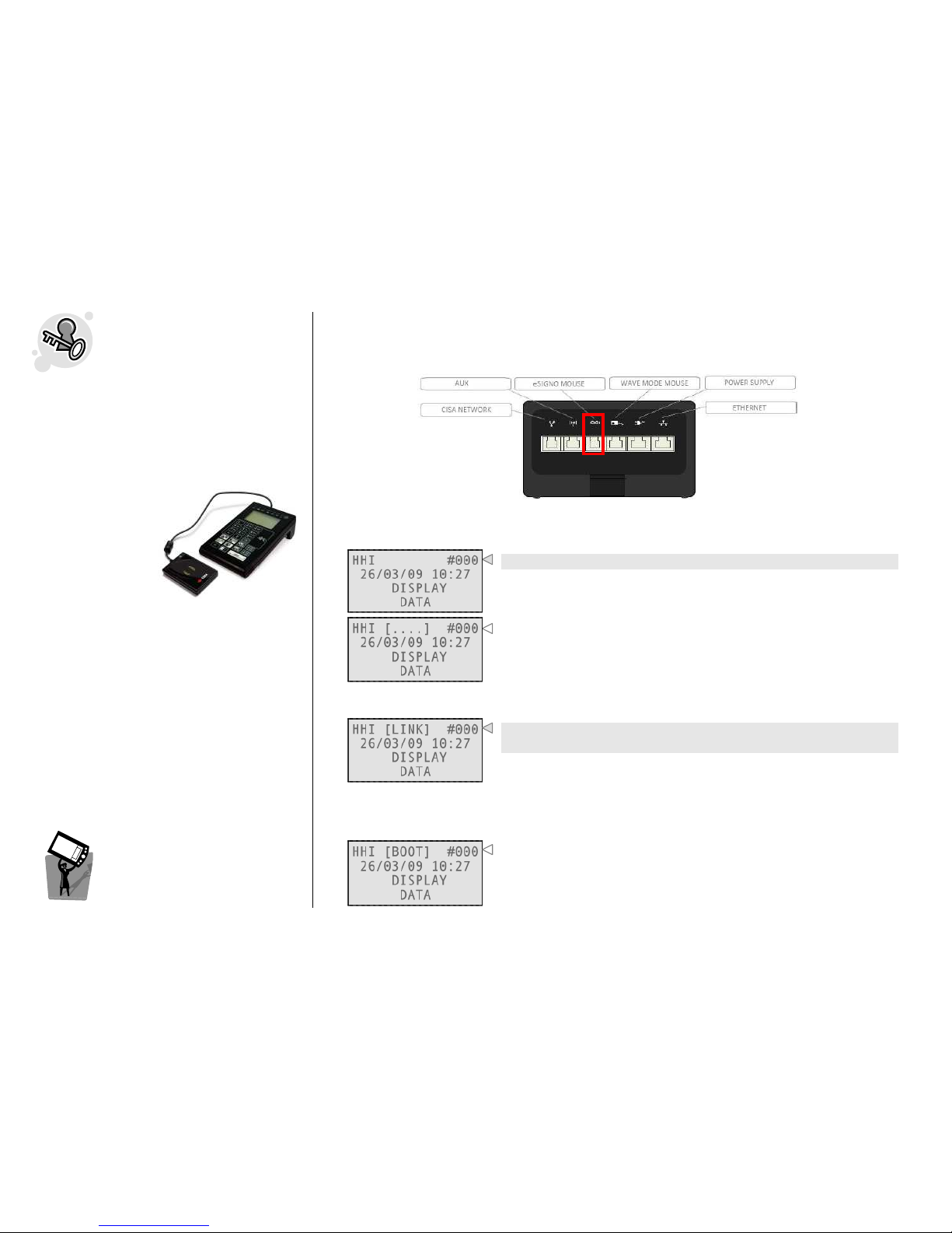
ESIGNO_SYSTEM_USER_MANUAL_101.DOCX 44/71
HHI
HHIHHI
HHI
M
MM
MODE
ODEODE
ODE:
::
:
EEE
ESIGNO
SIGNOSIGNO
SIGNO
LOCK AND WALL READER
LOCK AND WALL READERLOCK AND WALL READER
LOCK AND WALL READER
The eSIGNO Mobile in HHI mode allows the
operator to communicate with the electronic
devices inside the system (locks, wall readers and
E-cylinders).
The connection
with an eSIGNO
lock or wall reader
can be obtained
providing the
eSIGNO Mobile in
HHI mode with the
eSIGNO Mouse.
Thanks to this connection it is possible:
• to download firmware to the device;
• to initialize and synchronize the device;
• to manage the device’s memory (history
events, lock info, settings);
• to set autoprograms on the device;
• to change the device’s parameters.
Alternatively, communication between eSIGNO
Mobile and eSIGNO locks or wall readers can be
achieved by using Service Cards (see paragraph
below).
HHI
HHIHHI
HHI
M
MM
MODE
ODEODE
ODE
IIIINTRODUCTION
NTRODUCTIONNTRODUCTION
NTRODUCTION
COMMUNICATION BETWEEN HHI AND
COMMUNICATION BETWEEN HHI AND COMMUNICATION BETWEEN HHI AND
COMMUNICATION BETWEEN HHI AND eSIGNO LOCK
eSIGNO LOCK eSIGNO LOCK
eSIGNO LOCK OR
OROR
OR WALL READER
WALL READERWALL READER
WALL READER
To communicate with an eSIGNO device (lock or wall reader), connect the eSIGNO mouse to the
proper slot on the eSIGNO Mobile.
It is possible to understand if the eSIGNO mouse is correctly connected directly from the eSIGNO
Mobile’s screen:
The eSIGNO mouse is not connected to the eSIGNO Mobile.
The eSIGNO mouse is correctly connected to the eSIGNO Mobile
(see [….] on the first line).
To obtain the actual communication between the eSIGNO device (lock or wall reader) and the HHI,
the eSIGNO mouse has to be hung on the device.
The connection between eSIGNO device and HHI is on
(see [LINK] on the first line).
When communication has been established, the eSIGNO device remains turned on as long as the
eSIGNO mouse is maintained in front of its reader. From this moment on, it is possible to use the
dedicated short cut keys on the eSIGNO Mobile to perform several operations.
Note
NoteNote
Note: upon connection, if the eSIGNO Mobile detects that the device
has no compatible eSIGNO firmware, this message shows on its
display (see [BOOT] on the first line).
Page 45
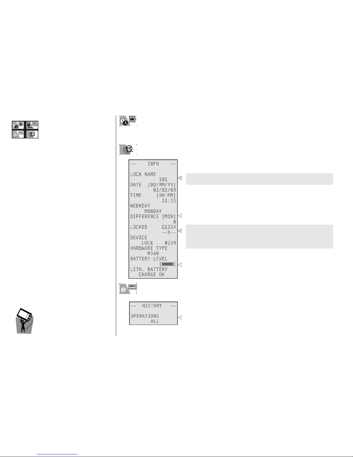
ESIGNO_SYSTEM_USER_MANUAL_101.DOCX 45/71
SSSSHORT
HORTHORT
HORT C
CC
CUT
UTUT
UT K
KK
KEYS
EYSEYS
EYS
HHI
HHIHHI
HHI
M
MM
MODE
ODE ODE
ODE
IIIINTRODUCTION
NTRODUCTIONNTRODUCTION
NTRODUCTION
LLLL
OCK
OCK OCK
OCK
SSSS
YNCHRONIZATION
YNCHRONIZATIONYNCHRONIZATION
YNCHRONIZATION
The HHI will send to the lock the real time and the daylight saving time tables.
After synchronizing, the lock gives 2 green lights.
IIII
NFORMATION
NFORMATIONNFORMATION
NFORMATION
With this function, it is possible to read information from the lock.
This field represents the lock name as in the keyplan; the lock logical
number is reported below.
This is the difference between lock time and encoding system time.
These are the kinds of locked cards (banned from opening the lock):
• G = guest cards;
• 1, 2, 3, 4 = staff cards type 1, 2, 3, 4.
In this case type 2 staff cards are locked.
These are the charge levels of the ordinary battery and the lithium
backup one.
LLLL
OCK
OCK OCK
OCK
HHHH
ISTORY
ISTORY ISTORY
ISTORY
RRRR
EAD
EAD EAD
EAD
OOOO
UT
UTUT
UT
With this function, it is possible to read a desired number of
operations performed on a particular lock, choosing between 10, 25,
50, 100 or ALL. After the read out, data can be either printed on
paper or displayed on the HHI. It is possible to read out operations
stored in many locks and load them all on the HHI, until the reaching
of maximum memory capability (up to 1000 operations).
Page 46
ESIGNO_SYSTEM_USER_MANUAL_101.DOCX 46/71
HHI
HHIHHI
HHI
M
MM
MODE
ODEODE
ODE:
::
:
E
EEE----CCC
CYLINDER
YLINDERYLINDER
YLINDER
The communication between the eSIGNO
Mobile in HHI mode and the E-Cylinder doesn’t
require the use of any mouse: it is accomplished
through the issue of Service cards, which must
then be presented to the E-Cylinder.
Note
NoteNote
Note: these Service cards can be also used as an
alternative way to achieve communication
between the eSIGNO Mobile and the eSIGNO
lock and wall reader.
HHI
HHIHHI
HHI
M
MM
MODE
ODE ODE
ODE
IIIINTRODUCTION
NTRODUCTIONNTRODUCTION
NTRODUCTION
COMMUNICATION BETWEEN HHI AND E
COMMUNICATION BETWEEN HHI AND ECOMMUNICATION BETWEEN HHI AND E
COMMUNICATION BETWEEN HHI AND E----CYLINDER
CYLINDERCYLINDER
CYLINDER
The Service cards used to accomplish the communication between the HHI and the E-Cylinder (or any
eSIGNO device in general) can be issued by selecting the proper option in the HHI menu (Service
Card Menu).
Then, navigating with , it is possible to choose the type of card to be issued. The different types of
Service cards are described in the table below.
Once issued, the card must be presented to the device:
• If the operation is being correctly executed, the device gives an orange light; at the end, it will give
two green blinks accompanied by two quick beeps;
• If the operation is not possible (e.g. when the device is not initialized), the device gives three red
blinks accompanied by two acute beeps (logical error situation);
• If the Service card is taken off the device while the operation is being executed, the device gives
one red blink accompanied by one acute beep (physical error situation).
Additional info about Service cards can be found in the Service Card Menu paragraph.
CARD
CARD CARD
CARD TYPE
TYPETYPE
TYPE WHAT IS IT FOR
WHAT IS IT FORWHAT IS IT FOR
WHAT IS IT FOR
SYNCHRO
SYNCHROSYNCHRO
SYNCHRO TO SYNCHRONIZE THE DEVICE WITH RESPECT TO THE ENCODER
INIT
INITINIT
INIT TO INITIALIZE THE DEVICE
RESET
RESETRESET
RESET TO RESET THE DEVICE
DEVICE INFO
DEVICE INFODEVICE INFO
DEVICE INFO
TO DOWNLOAD FROM THE DEVICE ALL THE INFORMATION ABOUT ITS
INITIALIZATION AND WORKING STATE
AUTOPROGRAMS
AUTOPROGRAMSAUTOPROGRAMS
AUTOPROGRAMS TO MANAGE AUTOPROGRAMS ON THE DEVICE
BATTERY CHANGE
BATTERY CHANGEBATTERY CHANGE
BATTERY CHANGE TO CHANGE THE E-CYLINDER BATTERIES (N/A FOR OTHER DEVICES)
MOUNT/DISMOUNT
MOUNT/DISMOUNTMOUNT/DISMOUNT
MOUNT/DISMOUNT
TO TAKE THE CYLINDER HEAD OFF ITS BODY (N/A FOR OTHER DEVICES)
Page 47
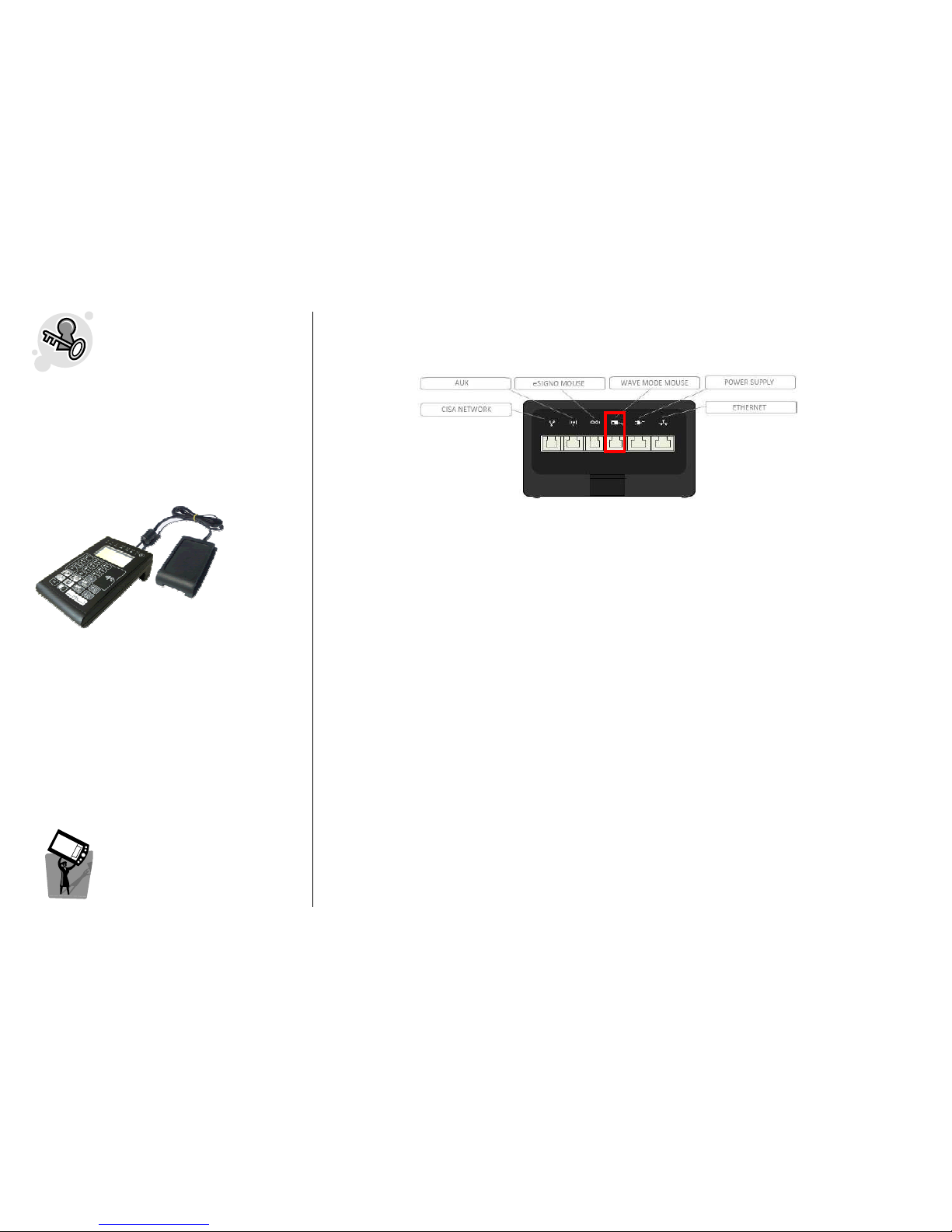
ESIGNO_SYSTEM_USER_MANUAL_101.DOCX 47/71
HHI
HHIHHI
HHI
M
MM
MODE
ODEODE
ODE:
::
:
W
WW
WAVE
AVE AVE
AVE
MMMMODE LOCK
ODE LOCKODE LOCK
ODE LOCK
The connection with a Wave Mode Lock can be
done providing the eSIGNO Mobile in HHI
mode with the Wave Mode Mouse (shown
below), which must be hung up on the Wave
Mode electronic lock.
Thanks to this connection it is possible:
• to download firmware to the lock;
• to initialize and synchronize the lock;
• to manage the lock’s memory (history events,
lock info, settings);
• to set autoprograms on the lock;
• to change the lock’s parameters.
HHI
HHIHHI
HHI
M
MM
MODE
ODE ODE
ODE
IIIINTRODUCTION
NTRODUCTIONNTRODUCTION
NTRODUCTION
COMMUNICATION BETWEEN THE HHI AND THE
COMMUNICATION BETWEEN THE HHI AND THE COMMUNICATION BETWEEN THE HHI AND THE
COMMUNICATION BETWEEN THE HHI AND THE WAVE MODE
WAVE MODE WAVE MODE
WAVE MODE LOCK
LOCKLOCK
LOCK
To communicate with a Wave Mode Lock, connect the Wave Mode Mouse to the proper slot on the
eSIGNO Mobile.
After the Wave Mode Mouse has been hung on the Wave Mode Lock, the operator must execute an
HHI command within 10 seconds; otherwise, the Wave Mode Lock turns off itself and communication
can't go on anymore. In this case, it is necessary to remove the Wave Mode Mouse from the mask of
the Wave Mode Lock and re-hang it again to repeat the operation. This procedure is necessary only
for the first command that the HHI has to send to the Wave Mode Lock; when this first command has
been executed correctly (i.e. when the HHI concludes with success the command sent to the lock), it is
not necessary to remove the Wave Mode Mouse from the mask of the lock for another command,
because now HHI has established a continue communication with it: every other command sent from
HHI to the lock will be executed immediately.
Notes
NotesNotes
Notes: the blinking of the red LED right to the battery one, on the HHI, means that the Wave Mode
Mouse has established a stable communication with the Wave Mode Lock. In this way HHI can
execute several commands, with the Wave Mode Lock answering immediately.
The Wave Mode Lock is normally turned off, waiting for a Wave Mode Card to read.
• When a Wave Mode Card or the Wave Mode Mouse is placed near the mask of the lock, the
electronic unit of the Wave Mode Lock turns on itself and tries to communicate for 5 seconds.
• If the lock doesn't recognize a Wave Mode Card within this time period, it then tries to establish
communication with HHI for other 5 seconds.
• If the lock doesn't recognize a command from the HHI within these last 5 seconds, it turns off itself.
Otherwise, it will execute it and remain turned on, in order to answer to other HHI commands sent
by the operator.
• When the operator removes the Wave Mode Mouse from the mask of the Wave Mode Lock, the
lock will turn off itself within 5 seconds.
When the communication with the lock has been established, it is possible to use the dedicated short
cut keys to perform several operations.
Page 48
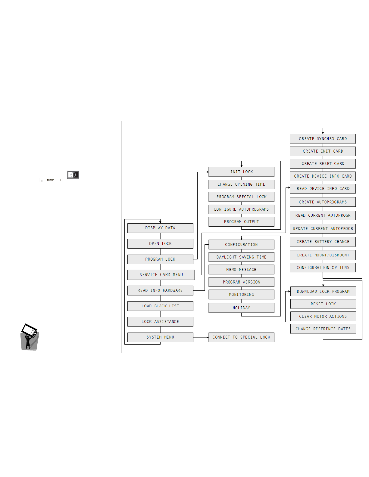
ESIGNO_SYSTEM_USER_MANUAL_101.DOCX 48/71
HHI
HHIHHI
HHI
M
MM
MAIN
AIN AIN
AIN M
MM
MENU
ENUENU
ENU
This special menu allows several functions to be
performed, depending on operator hierarchy.
To access this menu, log in HHI Mode; navigate
through its options with and confirm your
choice with .
HHI
HHIHHI
HHI
M
MM
MODE
ODEODE
ODE
MMMMENU
ENUENU
ENU
Page 49
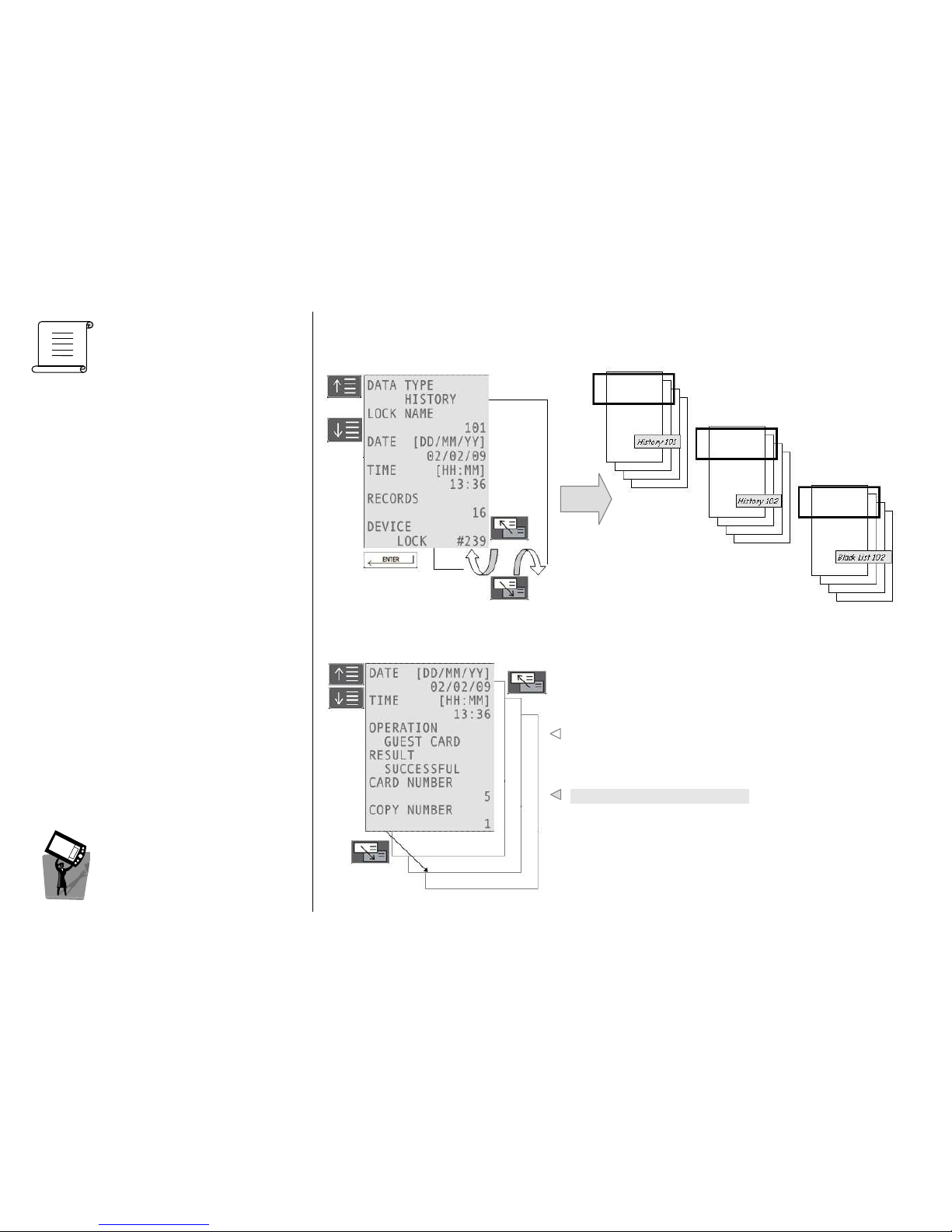
ESIGNO_SYSTEM_USER_MANUAL_101.DOCX 49/71
D
DD
DISPLAY
ISPLAY ISPLAY
ISPLAY D
DD
DATA
ATAATA
ATA
((((1111))))
HHI
HHIHHI
HHI
M
MM
MODE
ODE ODE
ODE
MMMMENU
ENUENU
ENU
From this menu, it is possible to display different information read outs, in particular the history and
black list of different locks. Data descriptors start from the most recent to the older one; each descriptor
consists in a set of records.
HISTORY
HISTORYHISTORY
HISTORY DISPLAY DATA
DISPLAY DATADISPLAY DATA
DISPLAY DATA
It will display the operations performed on the lock
starting from the last one.
This is the type of operation; below is its result
Here is the identifier of the card.
Page 50
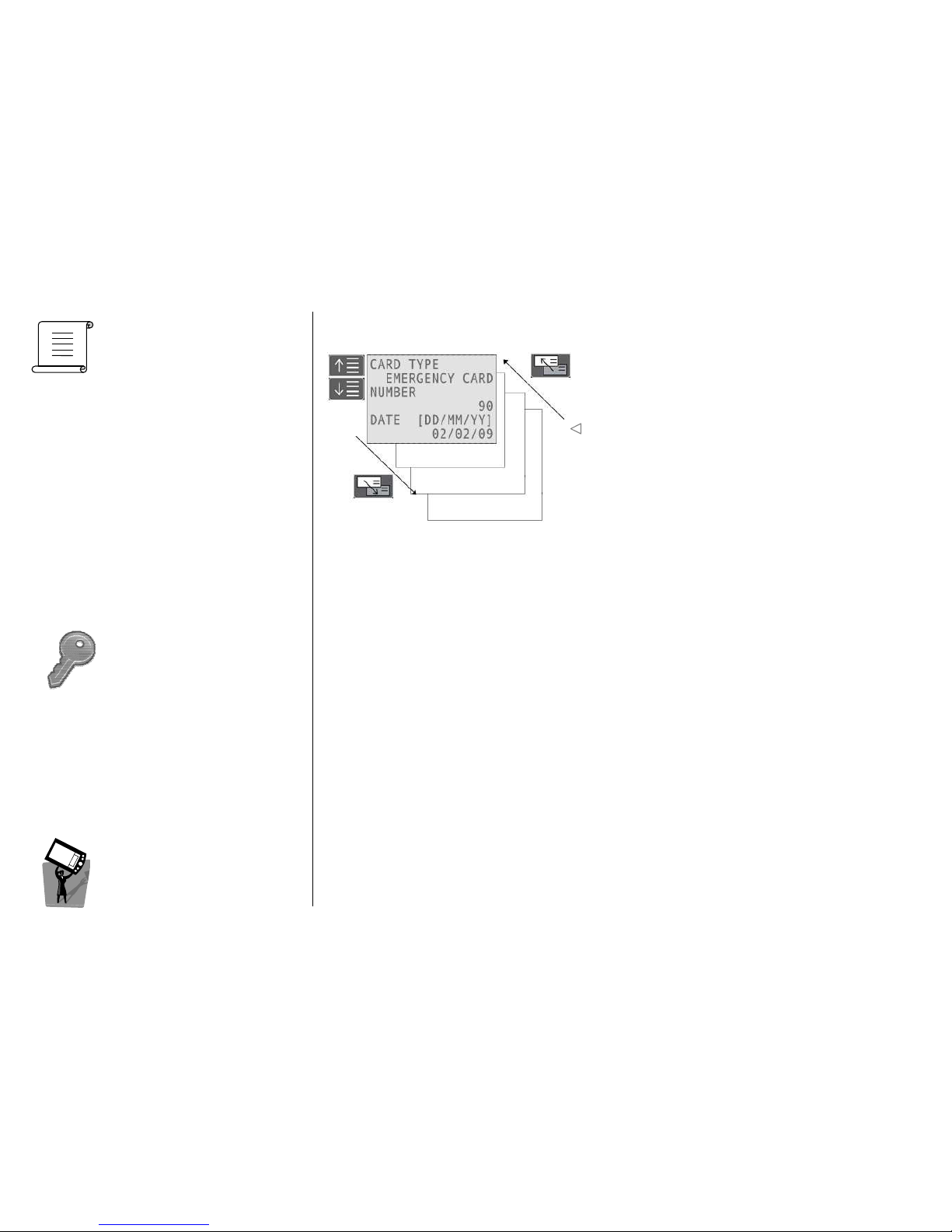
ESIGNO_SYSTEM_USER_MANUAL_101.DOCX 50/71
D
DD
DISPLAY
ISPLAY ISPLAY
ISPLAY D
DD
DATA
ATAATA
ATA
((((2222))))
O
OO
OPEN
PEN PEN
PEN L
LL
LOCK
OCKOCK
OCK
HHI
HHIHHI
HHI
M
MM
MODE
ODE ODE
ODE
MMMMENU
ENUENU
ENU
BLACK LIST DISPLAY DATA
BLACK LIST DISPLAY DATABLACK LIST DISPLAY DATA
BLACK LIST DISPLAY DATA
It will display the cancelled cards on the lock, i.e. the
cards in the lock black list.
Beginning of card validity
Selecting this option of the menu, the lock connected to the HHI will be opened.
It is important to note that the lock has to be connected to the HHI before it is possible to open it; the
connection can be obtained by selecting the System Menu and then the Connect to Special Lock
voice.
Note
NoteNote
Note: on wireless locks, it is possible to perform this operation by remote.
Page 51
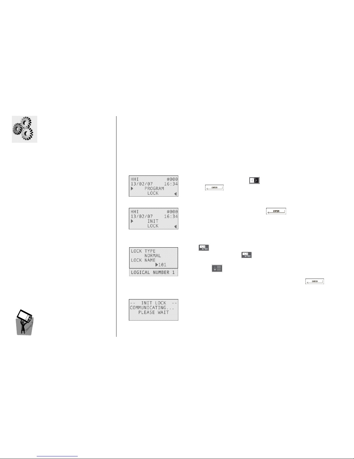
ESIGNO_SYSTEM_USER_MANUAL_101.DOCX 51/71
P
PP
PROGRAM
ROGRAM ROGRAM
ROGRAM L
LL
LOCK
OCKOCK
OCK
((((1111))))
HHI
HHIHHI
HHI
M
MM
MODE
ODE ODE
ODE
MMMMENU
ENUENU
ENU
IIII
NITIALIZE
NITIALIZENITIALIZE
NITIALIZE
LLLL
OCK
OCKOCK
OCK
Each door needs to be initialized with a specific number and with specific parameters.
1111
To initialize the lock press , then choose Program Lock by
pressing .
2222
Select the Init Lock option by pressing .
Note
NoteNote
Note: if the lock is already initialised, you have to reset it before
re-initialising it (Reset Lock option in Lock Assistance menu).
3333
Type the number you want to assign to the door (e.g. 101), then
press .
Alternatively, simply press to navigate through the available lock
numbers.
By pressing you can visualize the logical number assigned to the
door.
To confirm your choice and begin the initialization, press .
4444
Initializaion data are now being transmitted to the lock.
If the communication is successful, the lock will display a succession of
two green, one red and two green blinks.
This procedure will send to the electronic lock, the name, time, groups
and daylight savings time.
Page 52
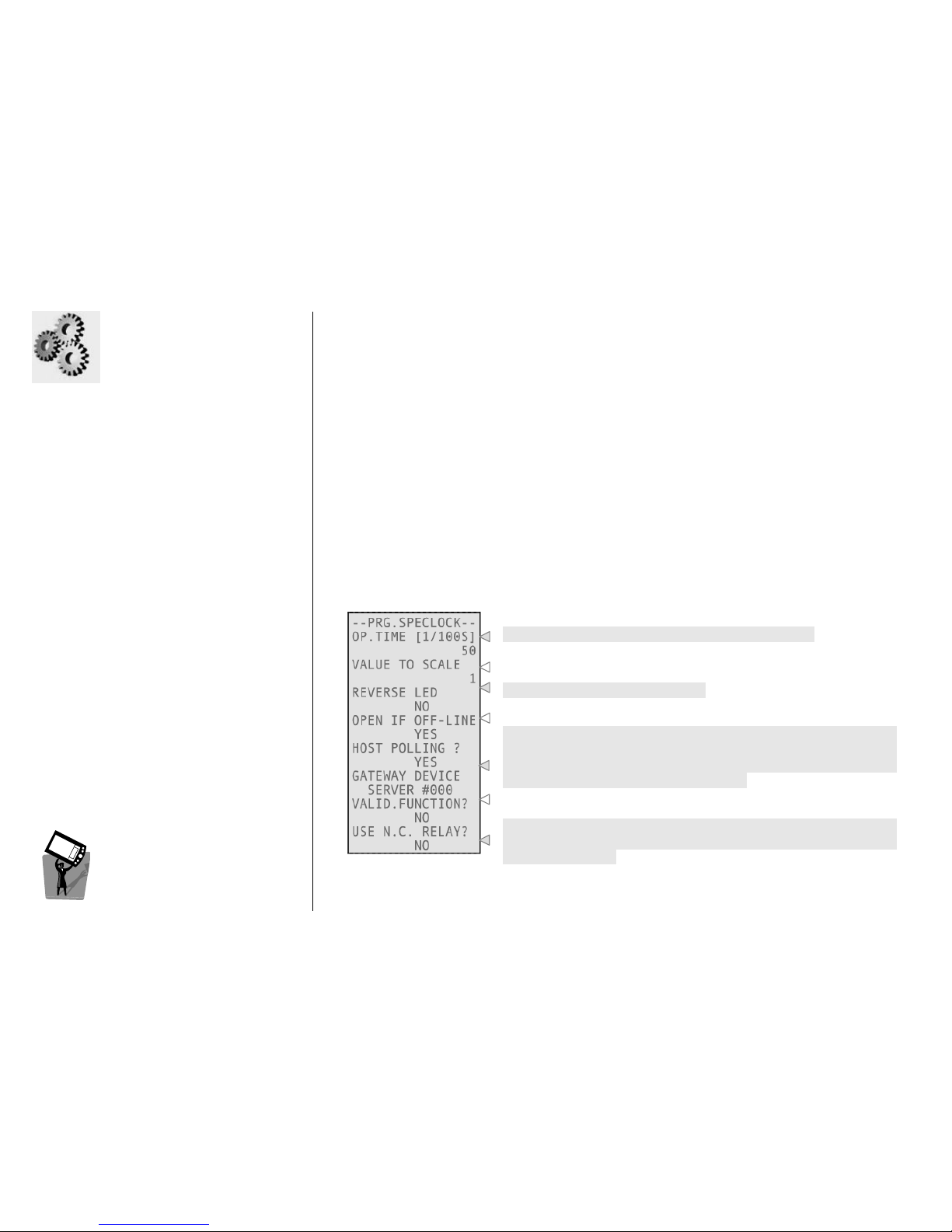
ESIGNO_SYSTEM_USER_MANUAL_101.DOCX 52/71
PPPPROGRAM
ROGRAM ROGRAM
ROGRAM L
LL
LOCK
OCKOCK
OCK
(2
(2(2
(2))))
HHI
HHIHHI
HHI
M
MM
MODE
ODE ODE
ODE
MMMMENU
ENUENU
ENU
CCCC
HANGE
HANGE HANGE
HANGE
OOOO
PENING
PENING PENING
PENING
TTTT
IME
IMEIME
IME
From this menu it is possible to set:
• Opening time
Opening timeOpening time
Opening time: this function cannot be used for special locks (see the paragraph below);
• Access time
Access timeAccess time
Access time: time period where the door is open after which a delayed close operation is written in
the door’s history;
• Maximum Motor idle
Maximum Motor idleMaximum Motor idle
Maximum Motor idle: sets the day delay between last and current motor activations by an Auto
Motor On autoprogram;
• Enable Auto
Enable AutoEnable Auto
Enable Auto----relock
relockrelock
relock: in an engaged lock with Office function active, presenting a card or inserting
privacy from the inside acts like a toggle switch for engaging or disengaging the lock.
PPPP
ROGRAM
ROGRAM ROGRAM
ROGRAM
SSSS
PECIAL
PECIAL PECIAL
PECIAL
LLLL
OCK
OCKOCK
OCK
This menu allows you to modify the default values of the specific parameters for special locks.
Opening time of the relay (from 1/100 to 600 seconds).
Using access on payment with credits, this is the value to decrement
from the guests credits.
Feature used on Smart systems only.
Specifies what to do if an online special lock goes off line.
These two fields are useful to configure the communication with
History Collection Protocol (HCP). If you set No, the special lock sends
data via serial cable to the device selected below; by setting Yes, the
selected device asks data to the special lock.
It allows you to enable the validator function for this lock (this is
possible if recoding function is enabled).
Changing this value permits to invert the logic of contacts into a M306
special lock (which has two contacts, by default a common one and a
normally open one).
Page 53
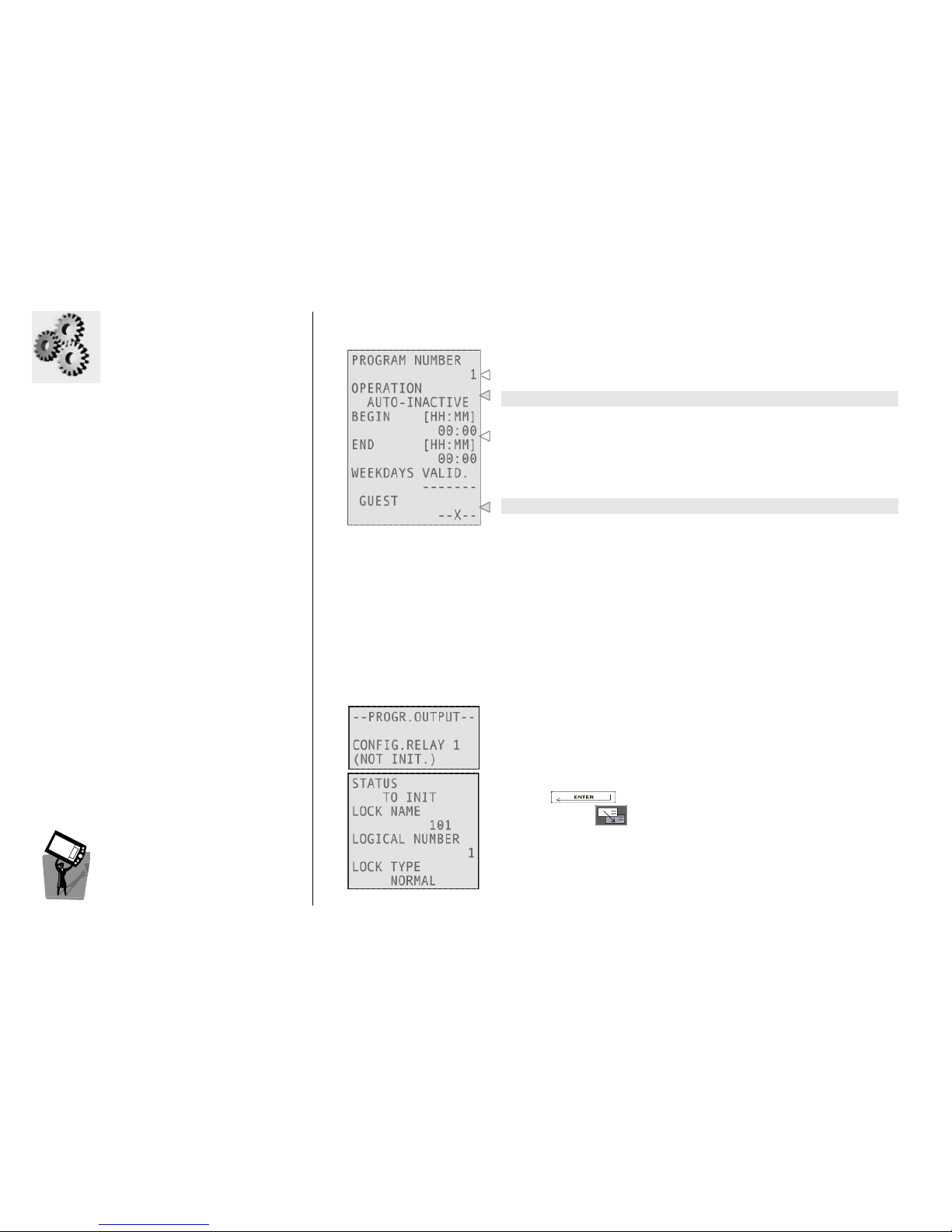
ESIGNO_SYSTEM_USER_MANUAL_101.DOCX 53/71
P
PP
PROGRAM
ROGRAM ROGRAM
ROGRAM L
LL
LOCK
OCKOCK
OCK
((((3333))))
HHI
HHIHHI
HHI
M
MM
MODE
ODE ODE
ODE
MMMMENU
ENUENU
ENU
CCCC
ONFIGURE
ONFIGURE ONFIGURE
ONFIGURE
AAAA
UTOPROGRAMS
UTOPROGRAMSUTOPROGRAMS
UTOPROGRAMS
This menu allows you to program automatic functions in the specified days and hours.
You can set up to 15 programs for normal locks and up to 60
programs for special locks.
This is the operation type (see below).
Beginning and end of autoprogram period of validity (with 15
minutes tolerance) and weekdays of validity.
It is possible to lockout several types of cards (Guest, Staff 1, 2, 3, 4).
These are the possible operations:
• AUTO-OFFICE ON: the lock is always open during the specified time shift;
• AUTO-LOCK OUT: it locks out the specified cards (Guest, Staff 1, 2, 3, 4) for the specified time shift;
• AUTO-MOTOR ON: this function actives the motor inside the lock for a cycle of 5 sec. It can be
useful to prevent motor blocking in particular hostile environment of installation. This autoprogram
is regulated by a parameter inside the Change Opening Time menu, called MAX MOT.IDLE [DD]: it
permits to set the day delay between last and current motor activations by the autoprogram;
• AUTO-INACTIVE: current autoprogram is not configured.
PPPP
ROGRAM
ROGRAM ROGRAM
ROGRAM
OOOO
UTPUT
UTPUTUTPUT
UTPUT
This function is available in plants with an installed Multi Input Output
device: this is a special device which capable of extending the capacity
of a special access control unit, adding up to 48 other special doors. It
can be used, for example, for special applications such as elevators.
Pressing you can initialize the relay 1.
Navigating with you can select a different relay to configure.
Page 54
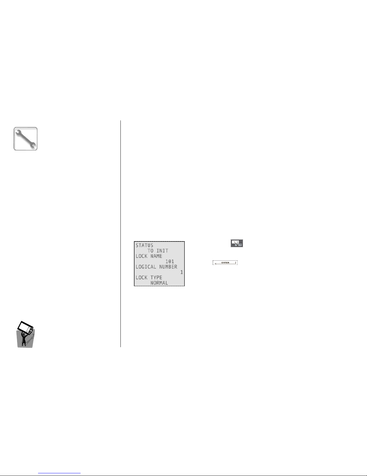
ESIGNO_SYSTEM_USER_MANUAL_101.DOCX 54/71
SSSSERVICE
ERVICE ERVICE
ERVICE C
CC
CARD
ARD ARD
ARD M
MM
MENU
ENUENU
ENU
((((1111))))
HHI
HHIHHI
HHI
M
MM
MODE
ODE ODE
ODE
MMMMENU
ENUENU
ENU
CCCC
REATE
REATE REATE
REATE
SSSS
YNCHRO
YNCHRO YNCHRO
YNCHRO
CCCC
ARD
ARDARD
ARD
This menu allows the creation of a Synchro service card. With this specific card, it is possible to
synchronize the device with respect to the encoder which issued it.
This operation can be performed by issuing a Synchro card and then presenting it to the device; when
completed, the device gives two green blinks. Such operation is necessary during the plant start-up or
after a device battery change.
In particular, a Synchro card permits the device to acquire from the encoder the following information:
• date and time;
• the daylight saving time settings;
• the holidays settings (which days of the year are considered as holidays).
Note
NoteNote
Note: it is important to present the Synchro card to the device just after issuing it, in order to preserve
its function of date and time alignment between device and encoder. After a synchronization has
been performed, the Difference [min] field in the device info should contain a 0 value.
CCCC
REATE
REATE REATE
REATE
IIII
NIT
NIT NIT
NIT
CCCC
ARD
ARDARD
ARD
This menu allows the creation of an Init card. With this specific card, it is possible to initialize a device as
(with the name of) one of the locks included in the keyplan.
Navigating with you can select the lock name that the device
will assume after the initialization.
Pressing you will confirm the creation of a device Init card
for the selected lock name.
The card must then be presented to the device; when the operation is
complete, the device gives two green blinks.
It is necessary to reset the device before presenting this card; If the device is already initialized when
presenting an Init card, it returns three red blinks while beeping twice.
CCCC
REATE
REATE REATE
REATE
RRRR
ESET
ESET ESET
ESET
CCCC
ARD
ARDARD
ARD
This menu allows the creation of a Reset card. With this specific card, it is possible to reset a device to
an out-of-.factory state. After this operation, the device can be re-initialized and synchronized.
Note
NoteNote
Note; the only card accepted by a device in Reset state is an Init card. To make other cards work, it is
necessary to initialize the device.
Page 55
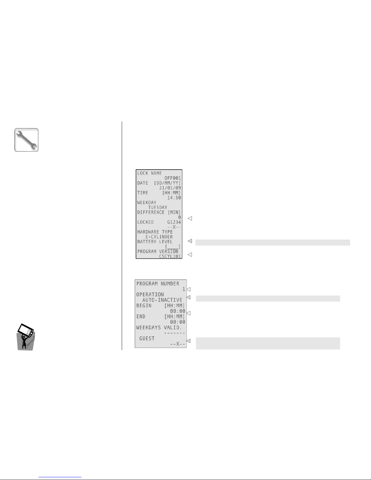
ESIGNO_SYSTEM_USER_MANUAL_101.DOCX 55/71
S
SS
SERVICE
ERVICE ERVICE
ERVICE C
CC
CARD
ARD ARD
ARD M
MM
MENU
ENUENU
ENU
(2)
(2)(2)
(2)
HHI
HHIHHI
HHI
M
MM
MODE
ODE ODE
ODE
MMMMENU
ENUENU
ENU
CCCC
REATE
REATE REATE
REATE
DDDD
EVICE
EVICE EVICE
EVICE
IIII
NFO
NFONFO
NFO
CCCC
ARD
ARDARD
ARD
This menu allows the creation of a Device Info service card. With this specific card, it is possible to
download from the device all the information about its initialization, date and time settings, battery
level and software version. This operation can be performed by encoding the card and then
presenting it to the device; when the operation is complete, the device gives two green blinks.
To read a Device Info card, it is necessary to use the proper menu (see below).
RRRR
EAD
EAD EAD
EAD
DDDD
EVICE
EVICE EVICE
EVICE
IIII
NFO
NFO NFO
NFO
CCCC
ARD
ARDARD
ARD
The information downloaded on the Device Info card can be
visualized on the encoder’s screen by choosing this menu and
presenting the card to the encoder.
Time difference between device and encoder.
Device battery level.
Firmware version installed on the device.
CCCC
REATE
REATEREATE
REATE
AAAA
UTOPROGRAMS
UTOPROGRAMSUTOPROGRAMS
UTOPROGRAMS
This menu allows you to program automatic functions in the specified days and hours.
You can set up to 15 programs for normal locks and up to 60
programs for special locks.
This is the operation type (see below).
Beginning and end of autoprogram period of validity (with 15
minutes tolerance) and weekdays of validity.
It is possible to lockout several types of cards (Guest, Staff 1, 2, 3,
4).
Page 56

ESIGNO_SYSTEM_USER_MANUAL_101.DOCX 56/71
S
SS
SERVICE
ERVICE ERVICE
ERVICE C
CC
CARD
ARD ARD
ARD M
MM
MENU
ENUENU
ENU
(3)
(3)(3)
(3)
HHI
HHIHHI
HHI
M
MM
MODE
ODE ODE
ODE
MMMMENU
ENUENU
ENU
These are the possible operations:
• AUTO-OFFICE ON: the lock is always open during the specified time shift;
• AUTO-LOCK OUT: it locks out the specified cards (Guest, Staff 1, 2, 3, 4) for the specified time shift;
• AUTO-MOTOR ON: this function actives the motor inside the lock for a cycle of 5 sec. It can be
useful to prevent motor blocking in particular hostile environment of installation. This autoprogram
is regulated by a parameter inside the Change Opening Time menu, called MAX MOT.IDLE [DD]: it
permits to set the day delay between last and current motor activations by the autoprogram;
• AUTO-INACTIVE: current autoprogram is not configured.
RRRR
EAD
EADEAD
EAD
/U
/U/U
/U
PDATE
PDATEPDATE
PDATE
CCCC
URRENT
URRENT URRENT
URRENT
AAAA
UTOPROGRAMS
UTOPROGRAMSUTOPROGRAMS
UTOPROGRAMS
The Read Current Autoprograms menu allows you to encode a dedicated service card, to be
presented to a device; in this way, all the details about the autoprograms currently residing inside the
device will be downloaded into the card. Then, by entering the Update Current Autoprograms menu,
the user is asked to present the card to the encoder, which uploads all the autoprograms’ details. It is
now possible to edit all these details. After confirming the changes, the encoder asks for the card to be
re-encoded. By presenting the card to the device again, all the residing autoprograms will be updated.
CCCC
REATE
REATE REATE
REATE
BBBB
ATTERY
ATTERY ATTERY
ATTERY
CCCC
HANGE
HANGEHANGE
HANGE
This menu allows the creation of a Battery Change service card. With this specific card, it is possible to
change the cylinder batteries. By presenting the card to the cylinder, the two pins blocking the
cylinder head carter become retractable; now, it is possible to take the carter off the cylinder head by
using the proper tool and to replace the batteries. After that, the cylinder head carter can be put in
place again and blocked by presenting the Battery Change card a second time.
CCCC
REATE
REATE REATE
REATE
MMMM
OUNT
OUNTOUNT
OUNT
/D
/D/D
/D
ISMOUNT
ISMOUNTISMOUNT
ISMOUNT
This menu allows the creation of a Mount/Dismount service card. With this specific card, it is possible
to take the cylinder head off its body. By presenting the card to the cylinder, the cylinder head
becomes integral with the cam; to take the head off the cylinder body, rotate it while pulling; the
opposite operation can be done by putting the head back in place and presenting the
Mount/Dismount service card a second time.
CCCC
ONFIGURATION
ONFIGURATION ONFIGURATION
ONFIGURATION
OOOO
PTIONS
PTIONSPTIONS
PTIONS
This menu allows to set the duration (in days) of the service cards issued through the previous menus
(Synchro, Init, Reset, Device Info, Autoprograms, Battery Change, Mount/Dismount). The default
duration is 365 days.
Page 57
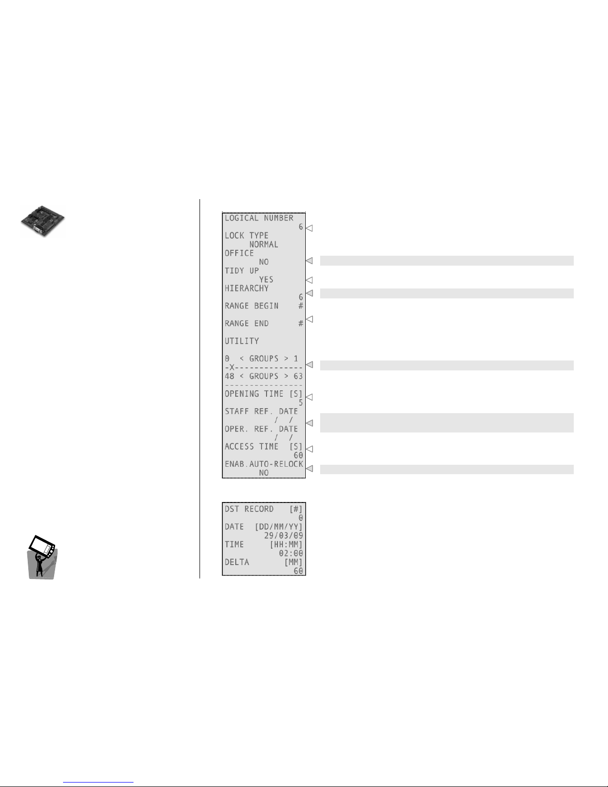
ESIGNO_SYSTEM_USER_MANUAL_101.DOCX 57/71
RRRREAD
EAD EAD
EAD I
II
INFO
NFONFO
NFO
HHHHARDWARE
ARDWAREARDWARE
ARDWARE
((((1111))))
It will display detailed lock information.
HHI
HHIHHI
HHI
M
MM
MODE
ODE ODE
ODE
MMMMENU
ENUENU
ENU
CONFIGURATION
CONFIGURATIONCONFIGURATION
CONFIGURATION
Logical number and name of the lock.
Is Office function enabled?
Is Tidy Up function enabled?
Minimum HHI operator hierarchy level for the lock.
For common doors only, it is the range of doors beyond the present
one.
Which groups include this lock?
This parameter can be set in the Change Opening Time menu.
Reference date for cards validity (i.e. all valid cards issued before this
date open the door no more).
This parameter can be set in the Change Opening Time menu.
This parameter can be set in the Change Opening Time menu.
DAYLIGHT SAVING TIME
DAYLIGHT SAVING TIMEDAYLIGHT SAVING TIME
DAYLIGHT SAVING TIME
There are 20 records (from 0 to 19) to be selected, in order to see the
DST periods on the lock. Each one includes:
• Date;
• Time;
• Delta to be applied.
The record 0 is the next change of time date.
Page 58
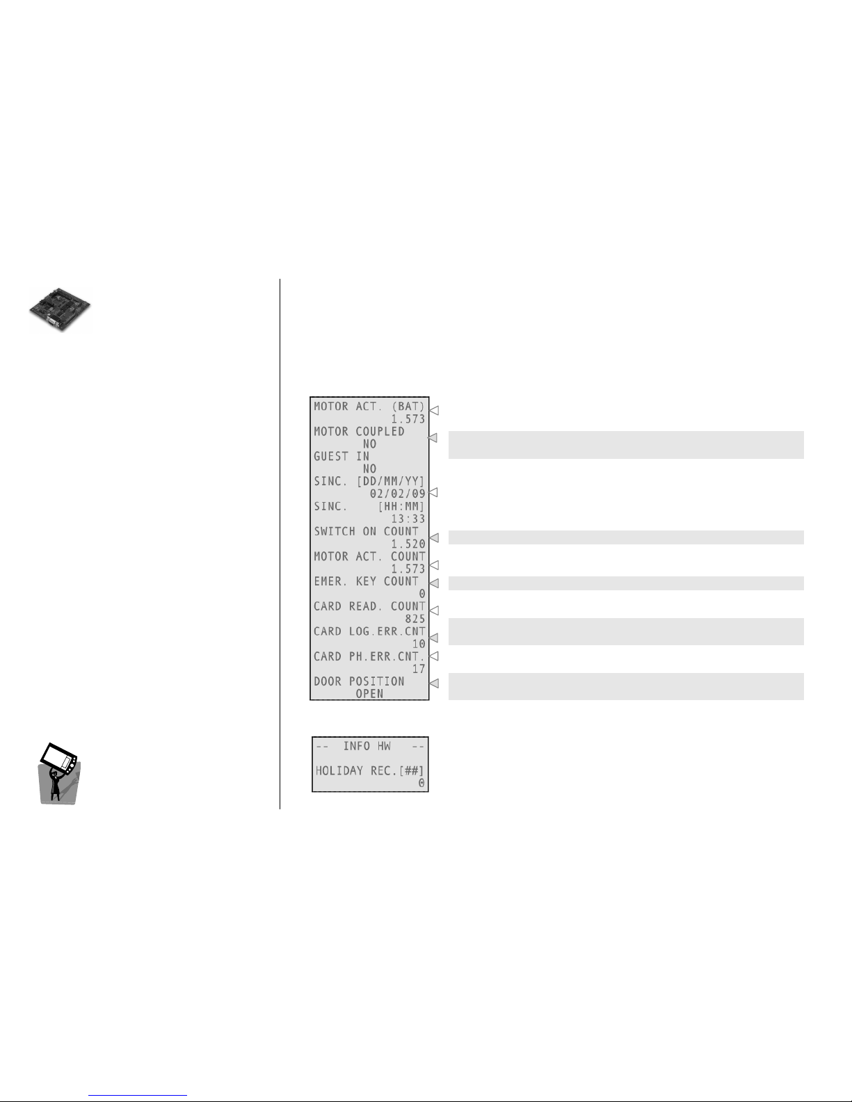
ESIGNO_SYSTEM_USER_MANUAL_101.DOCX 58/71
R
RR
READ
EAD EAD
EAD I
II
INFO
NFO NFO
NFO
H
HH
HARDWARE
ARDWAREARDWARE
ARDWARE
((((2222))))
It will display detailed lock information.
HHI
HHIHHI
HHI
M
MM
MODE
ODE ODE
ODE
MMMMENU
ENUENU
ENU
MEMO MESSAGE
MEMO MESSAGEMEMO MESSAGE
MEMO MESSAGE
It reads out a memo message eventually stored on the lock; this message is customizable via the
CS9500 Configurator software.
PROGRAM VERSION
PROGRAM VERSIONPROGRAM VERSION
PROGRAM VERSION
It reads out the program release installed on the lock.
MONITORING
MONITORINGMONITORING
MONITORING
Number of motor actions done with the current batteries.
These fields display if the lock is engaged and if the guest is in the
room.
Date and time of last synchronization.
Count of times the lock has switched on.
Number of motor actions done during lock lifetime.
Number of times that an emergency card has been used on this lock.
Number of Read Card operations completed successfully.
Number of logical errors during Read Card operations due, for
example, to wrong plant code (the lock gives 3 red blinks).
Number of physical errors during Read Card operations, due to card
malfunctions or human error (lock gives 1 red blink).
With Door Position Reporting function enabled, this field says if the
door is Open or Closed.
HOLIDAY
HOLIDAYHOLIDAY
HOLIDAY
In this menu, you have to type first the number of record you want to
see. Each record contains an holiday date; these dates can be set only
through Smart Software.
Page 59
ESIGNO_SYSTEM_USER_MANUAL_101.DOCX 59/71
L
LL
LOAD
OAD OAD
OAD B
BB
BLACK
LACK LACK
LACK L
LL
LIST
ISTIST
IST
L
LL
LOCK
OCK OCK
OCK A
AA
ASSISTANCE
SSISTANCESSISTANCE
SSISTANCE
These functions are reserved for technical
assistance.
S
SS
SYSTEM
YSTEM YSTEM
YSTEM M
MM
MENU
ENUENU
ENU
HHI
HHIHHI
HHI
M
MM
MODE
ODE ODE
ODE
MMMMENU
ENUENU
ENU
By choosing this option, the list of the cards stored in the lock black list will be loaded; this list can be
then visualized on the eSIGNO Mobile display or printed out.
DDDD
OWNLOAD
OWNLOAD OWNLOAD
OWNLOAD
LLLL
OCK
OCK OCK
OCK
PPPP
ROGRAM
ROGRAMROGRAM
ROGRAM
To upgrade the software inside the locks to a newer version, or in case of lock software loss, you have
to download the program onto the locks. Selecting this function brings you into another menu, where
you can select to only download the program, or reset the lock, or reset and download.
RRRR
ESET
ESET ESET
ESET
LLLL
OCK
OCKOCK
OCK
The lock will be reset.
CCCC
LEAR
LEAR LEAR
LEAR
MMMM
OTOR
OTOR OTOR
OTOR
AAAA
CTIONS
CTIONSCTIONS
CTIONS
After changing the batteries, it is possible to reset the opening counter, which records the number
of openings of the lock, so you can approximately estimate the battery status.
CCCC
HANGE
HANGE HANGE
HANGE
RRRR
EFERENCE
EFERENCE EFERENCE
EFERENCE
DDDD
ATES
ATESATES
ATES
It is possible to invalidate Staff and Operator cards starting from a specified date.
SSSSYSTEM
YSTEM YSTEM
YSTEM M
MM
MENU
ENUENU
ENU
The System Menu allows to establish a communication with special locks connected in network
(online locks).
CCCC
ONNECTION
ONNECTION ONNECTION
ONNECTION
TTTT
O
O O
O
SSSS
PECIAL
PECIAL PECIAL
PECIAL
LLLL
OCK
OCKOCK
OCK
Allows you to perform HHI operations on a special lock that is working in network: you must use this
option before starting any HHI operation on the online special lock.
In other words, this function has the same role for the online special lock as connecting the HHI cable
to a normal lock.
If you want, for example, to read out a history, you have to enter the System Menu, select Connection
To Special Lock, choose the lock you want to connect with, and then you can read the history as you
normally would in a standard lock.
Page 60
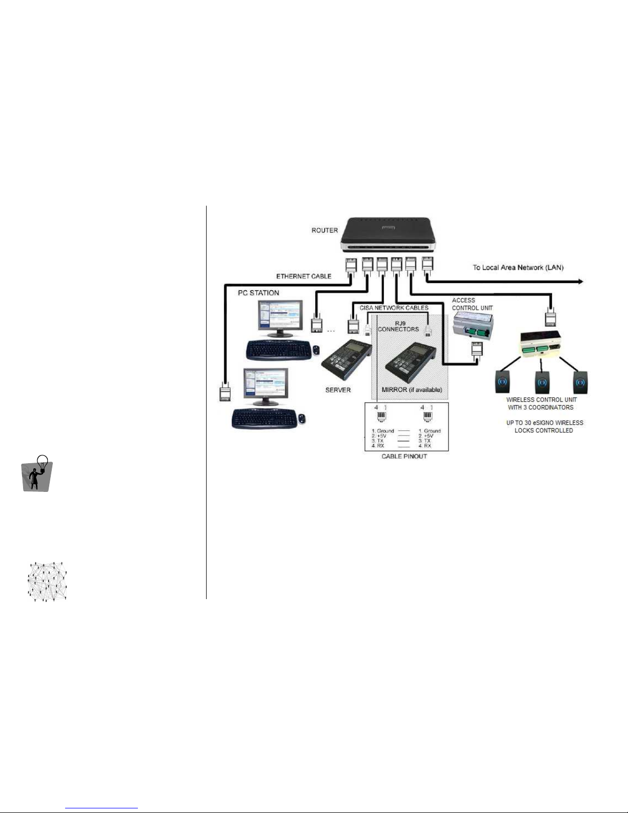
ESIGNO_SYSTEM_USER_MANUAL_101.DOCX 60/71
NNNNETWORKING
ETWORKINGETWORKING
ETWORKING
A network
networknetwork
network is a group of devices connected to
each other, through Ethernet cables or via
wireless.
The most essential network is composed by a
The most essential network is composed by a The most essential network is composed by a
The most essential network is composed by a
eSIGNO
eSIGNO eSIGNO
eSIGNO Mobile working as Server and a PC
Mobile working as Server and a PCMobile working as Server and a PC
Mobile working as Server and a PC; to
this configuration several other devices can be
added, depending on customer need:
• Clients
ClientsClients
Clients, essentially a number of eSIGNO
Mobiles, connected to the network in order
to have several independent cards issuing
points;
• Mirror
MirrorMirror
Mirror, an eSIGNO Mobile to backup Server’s
memory;
• Special locks
Special locksSpecial locks
Special locks (based on access control units);
• Wireless Control Units
Wireless Control UnitsWireless Control Units
Wireless Control Units, each connecting to
the system (via wireless) up to 30 eSIGNO
locks.
TIP
TIPTIP
TIP
All the encoding stations share the server’s
database; however, functionality and user
interface of each device are the same.
CCCCONNECTIONS
ONNECTIONSONNECTIONS
ONNECTIONS
CONNECTIONS
CONNECTIONSCONNECTIONS
CONNECTIONS
CONFIGURATION
CONFIGURATIONCONFIGURATION
CONFIGURATION
Here are the steps to configure each device included into the network:
• start the CS9500 Configurator program;
• create or open an existing plant configuration;
• click on Devices and select Server Encoder #00000;
• click on Properties, then select the M305 Hardware Type and the Ethernet Connection Box;
• type the device IP address (if integrating into an existing LAN network, a dedicated range of
IP
addresses must be reserved). Check that the Subnet Mask matches as well, then start download;
• for the Mirror, select the proper Hardware Type and start download (it will use the same IP address
as the server). The connection between Server and Mirror must be through a CISA Network Cable;
• for Special Locks, select the proper Hardware Type and Ethernet settings, then start download;
• for Wireless Control Units, select the proper Ethernet settings and start download. A different IP
address must be used for each Special Lock or Wireless Control Unit.
Page 61
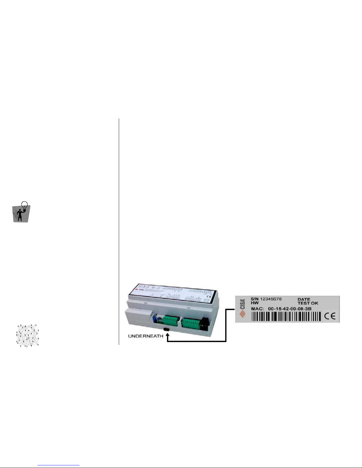
ESIGNO_SYSTEM_USER_MANUAL_101.DOCX 61/71
NNNNETWORKING
ETWORKING ETWORKING
ETWORKING H
HH
HARDWARE
ARDWAREARDWARE
ARDWARE
((((1111))))
TIP
TIPTIP
TIP
It is possible to configure two sub-networks,
placed in different physical locations, belonging
to the same network and connected through
routers and /or a radio link.
CCCCONNECTIONS
ONNECTIONSONNECTIONS
ONNECTIONS
SSSS
PECIAL
PECIAL PECIAL
PECIAL
LLLL
OCKS
OCKSOCKS
OCKS
The special access
special accessspecial access
special access control
controlcontrol
control unit
unitunit
unit allows, coupled with a card reader, to control an access point by using
a standard actuation device (e.g. electric strike, electric or motorized lock). They can be initialized as
standard, common or utility doors. Different access controls like electrical strike doors, elevators or car
parks can be controlled online
onlineonline
online with the encoding station, allowing access only to the active cards.
Due to the different possible applications and to the hardware used, some of the special lock
parameters have been increased:
• black list dimension with 80 positions;
• history of the last 800 operations on the door.
If the special lock is connected online, these added features are available:
• each time the card is approached to the reader, a real time check on the encoding system is
performed, and the opening is allowed only if the card is still active in the database;
• all the HHI operations (e.g. history read-out, synchronization) are performed with the HHI directly
connected to the network, without moving to the special access control.
The special lock is composed by one ccccontrol unit
ontrol unitontrol unit
ontrol unit and up to two card readers
card readerscard readers
card readers. The control unit has
relay contacts for the output, and the possibility to connect a backup external battery, which can
provide power to it and to the actuation device in case of main power supply loss.
There are two possible work modalities for a special lock:
• stand
standstand
stand----alone
alonealone
alone: it will work in the same way of a standard CISA lock, with the exception it will activate
a relay. You can initialize the lock with the HHI as you do for a normal CISA CS9500 lock (a special
cable for communication between HHI and the special lock is necessary);
• on
onon
on----line
lineline
line: it will work on the same network line of the encoding stations. All the HHI operations are
performed via network from the HHI, selecting on the HHI menu the special lock you want to
connect to instead of moving to the lock itself.
To get the MAC address
MAC addressMAC address
MAC address of a Special Lock #00081, view the sticker underneath the device.
Page 62
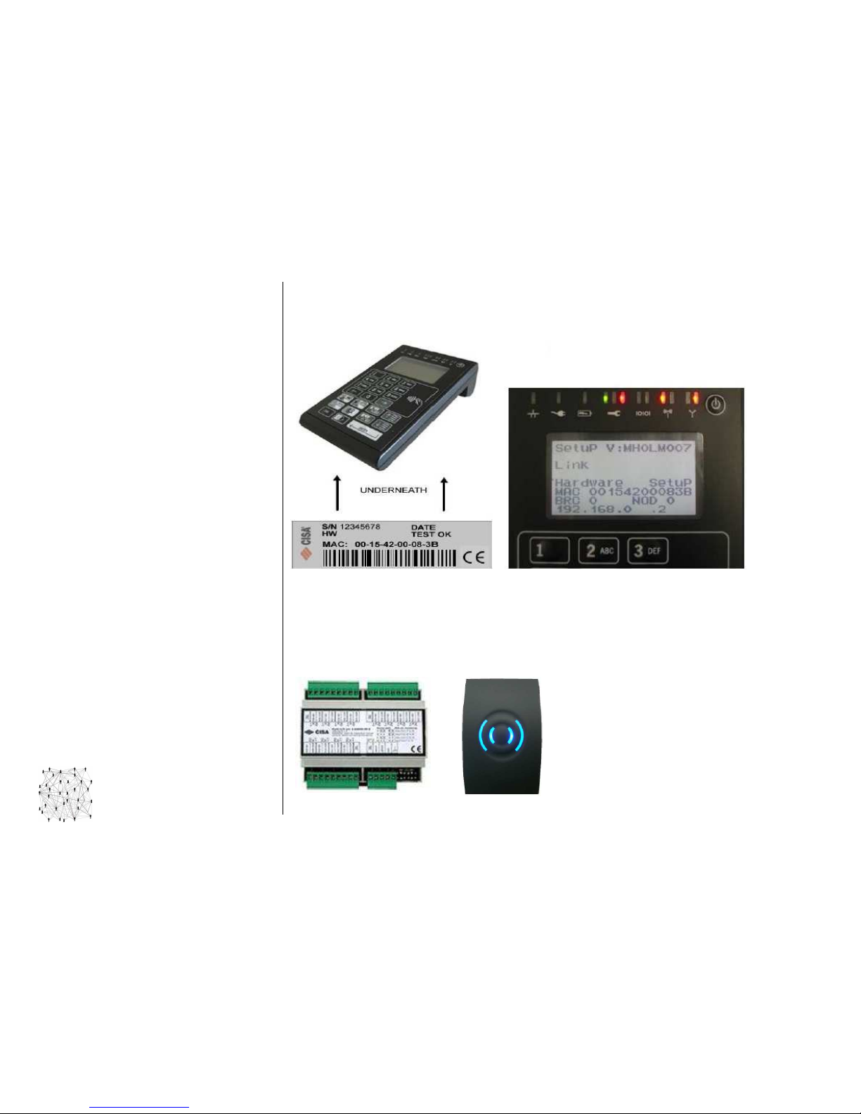
ESIGNO_SYSTEM_USER_MANUAL_101.DOCX 62/71
NNNNETWORKING
ETWORKING ETWORKING
ETWORKING H
HH
HARDWARE
ARDWAREARDWARE
ARDWARE
((((2222))))
CCCCONNECTIONS
ONNECTIONSONNECTIONS
ONNECTIONS
EEEE
SIGNO
SIGNOSIGNO
SIGNO
MMMM
OBILE
OBILE OBILE
OBILE
M305
M305M305
M305
To get the MAC address
MAC address MAC address
MAC address of the eSIGNO Mobile, initiate the device in Hardware Setup mode: with the
unit powered off, hold any keypad button while pressing power on, until hardware information
shows up. The MAC address is also written on a label underneath the eSIGNO Mobile.
MMMM
ULTI
ULTI ULTI
ULTI
IIII
NPUT
NPUT NPUT
NPUT
OOOO
UTPUT
UTPUTUTPUT
UTPUT
The Multi I/O module allows to extend the capacity of the special access control unit, adding from a
minimum of 12 up to a maximum of 48 relays (connect together 4 Multi I/O to the same control unit).
They can be used for special applications in which is required the control of more than one relay (e.g.
lift control panel). The Multi I/O interface is connected to the control unit together with one or more
external special readers.
Page 63
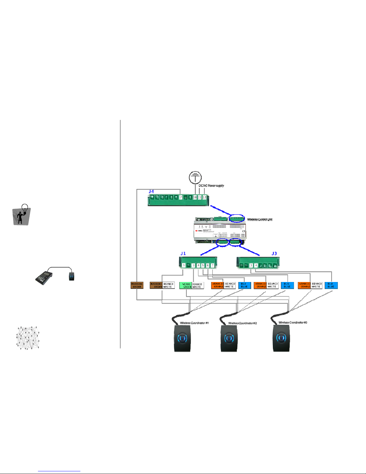
ESIGNO_SYSTEM_USER_MANUAL_101.DOCX 63/71
NNNNETWORKING
ETWORKING ETWORKING
ETWORKING H
HH
HARDWARE
ARDWAREARDWARE
ARDWARE
(3)
(3)(3)
(3)
TIP
TIPTIP
TIP
To perform wireless field analysis before
executing installation and to discover the
wireless channels to be associated to a group of
eSIGNO Wireless locks in relation with the
Wireless Coordinator, a special tool named
Wireless Analyser is available.
CCCCONNECTIONS
ONNECTIONSONNECTIONS
ONNECTIONS
WWWW
IRELESS
IRELESS IRELESS
IRELESS
CCCC
ONTROL
ONTROL ONTROL
ONTROL
UUUU
NIT
NITNIT
NIT
It links the central station to the eSIGNO Wireless locks (up to 30) and provides the physical
connection with up to 3 Wireless Coordinators. It is connected via Ethernet to the LAN network.
WWWW
IRELESS
IRELESS IRELESS
IRELESS
CCCC
OORDINATOR
OORDINATOROORDINATOR
OORDINATOR
It provides the radio connection through ZigBee between Wireless Control Unit and the
corresponding eSIGNO Wireless locks (up to 10). It is connected to the Wireless Control Unit through
a maximum 25 m long cable. Note: Wireless Coordinator is supplied with 10m cable length.
Page 64
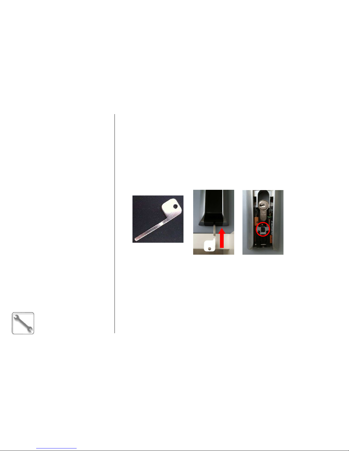
ESIGNO_SYSTEM_USER_MANUAL_101.DOCX 64/71
MMMMAINTENANCE
AINTENANCEAINTENANCE
AINTENANCE
((((1111))))
SSSSERVICE
ERVICE ERVICE
ERVICE O
OO
OPERATION
PERATIONPERATION
PERATIONSSSS
eeee
SIGNO
SIGNOSIGNO
SIGNO
LLLL
OCK
OCKOCK
OCK
BBBB
ATTERY
ATTERY ATTERY
ATTERY
SSSS
TATUS
TATUSTATUS
TATUS
The battery status control can be done using any valid staff card; there are 2 different warning levels:
• low battery status: the LED signal gives 3 red + green blinks before lock opening;
• end battery status: the LED signal gives 12 red + green blinks before lock opening.
These warnings are also recorded into lock history as separate events with respect to the openings.
Steps to change batteries:
Steps to change batteries:Steps to change batteries:
Steps to change batteries:
• with the proper tool, remove the lower plastic cover from the external plate;
• disconnect the batteries holder by pressing the central pin;
• replace the batteries (3 alkaline AAA LR3 type batteries are needed).
EEEE
MERGENCY
MERGENCY MERGENCY
MERGENCY
MMMM
ECHANIC
ECHANICECHANIC
ECHANICAL
ALAL
AL
CCCC
YLINDER
YLINDERYLINDER
YLINDER
The electronic locks always have an emergency mechanical cylinder with variable key bitting.
The cylinder works with 3 different keys (number from 1 to 3):
• key number 1 must be used first;
• in case of key number 1 has been lost or has not been considered secure, key number 2 can be
used. In this case the use of the key number 1 is blocked;
• in the same way, using key number 3, key number 2 will be disabled.
Independently from the key you are using, follow this procedure:
• expose the mechanical cylinder by removing the lower plastic cover from the external plate, using
the proper tool (see figure above);
• insert the mechanical key and turn 360° in the clockwise direction;
• rotate the knob (external handle).
Page 65
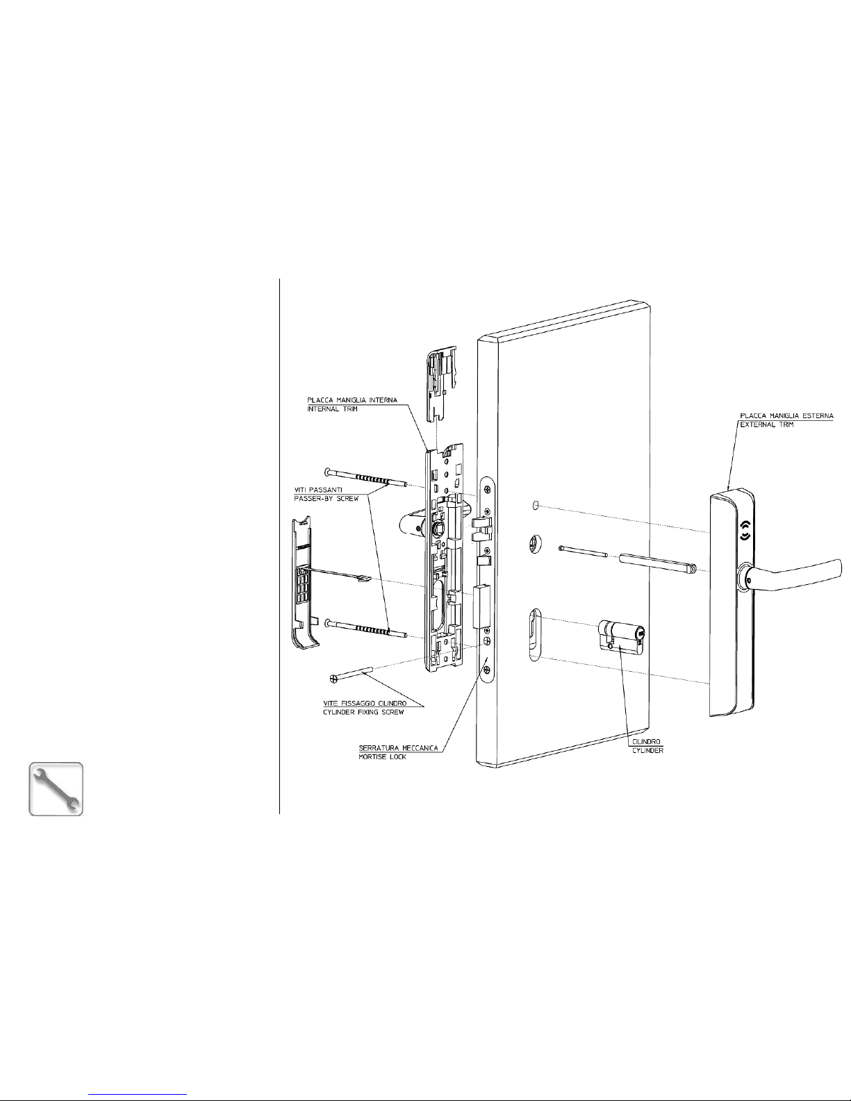
ESIGNO_SYSTEM_USER_MANUAL_101.DOCX 65/71
MMMMAINTENANCE
AINTENANCEAINTENANCE
AINTENANCE
((((2222))))
SSSSERVICE
ERVICE ERVICE
ERVICE O
OO
OPERATIONS
PERATIONSPERATIONS
PERATIONS
eeee
SIGNO
SIGNOSIGNO
SIGNO
LLLL
OCK
OCK OCK
OCK
IIII
NSTALLATION
NSTALLATIONNSTALLATION
NSTALLATION
Page 66
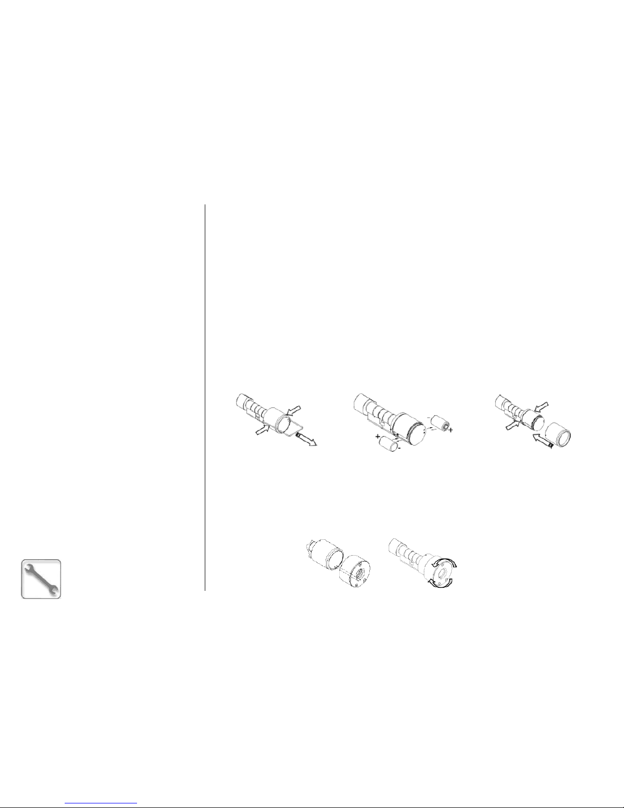
ESIGNO_SYSTEM_USER_MANUAL_101.DOCX 66/71
MMMMAINTENANCE
AINTENANCEAINTENANCE
AINTENANCE
((((3333))))
SSSSERVICE
ERVICE ERVICE
ERVICE O
OO
OPERATIONS
PERATIONSPERATIONS
PERATIONS
eeee
SIGNO
SIGNOSIGNO
SIGNO
EEEE
----
CCCC
YLINDER
YLINDERYLINDER
YLINDER
BBBB
ATTERY
ATTERY ATTERY
ATTERY
SSSS
TATUS
TATUSTATUS
TATUS
The battery status control can be done using any valid staff card. In case of low battery status, the LED
light signal gives 3 red + green blinks before the opening of the cylinder.
Note:
Note: Note:
Note: in case of unusable batteries (if they have not been changed since the signals above), after a
few openings the cylinder stops reacting to valid cards. To re-activate it, it is necessary to change the
batteries by using the external power supply adapter.
Steps to change batteries:
Steps to change batteries:Steps to change batteries:
Steps to change batteries:
1. Present a Change Battery Service card (issued in HHI mode).
2. The two pins blocking the cylinder head carter are now retractable. With the proper tool, take the
carter off the cylinder head.
3. Change batteries (2x lithium 3V CR-2 type); if polarity is correct, the cylinder will beep.
4. Push the two pins and insert the head carter, checking that the pins are in the correct position.
5. Present a Change Battery Service card again. The two pins are now solid.
6. Present a Synchro Service card to synchronize the E-Cylinder once again.
External power supply adapter
External power supply adapterExternal power supply adapter
External power supply adapter
In case the batteries are completely unusable, it is necessary to use the external power supply adapter
in order to recuperate the cylinder functionality. To achieve that, insert the adapter, checking that its
power supply pins are positioned coherently with the knob’s external power supply pins. If necessary,
slowly rotate the adapter in order to obtain the pins alignment; if the position is correct and the
batteries are depleted, the cylinder beeps once.
2222
3333
4444
Page 67
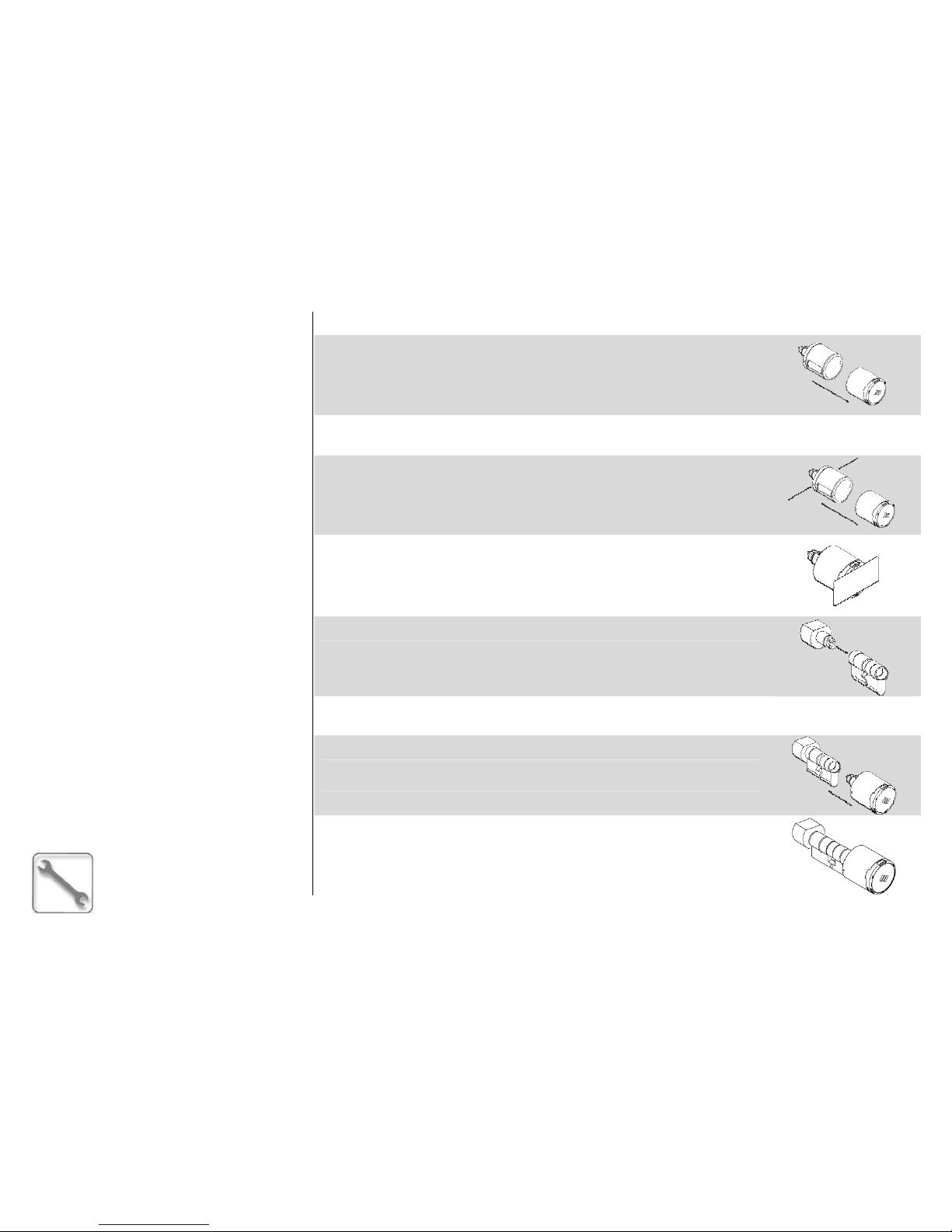
ESIGNO_SYSTEM_USER_MANUAL_101.DOCX 67/71
MMMMAINTENANCE
AINTENANCEAINTENANCE
AINTENANCE
(4)
(4)(4)
(4)
SSSSERVICE
ERVICE ERVICE
ERVICE O
OO
OPERATIONS
PERATIONSPERATIONS
PERATIONS
EEEE----CCCC
YLINDER
YLINDER YLINDER
YLINDER
IIII
NSTALLATION
NSTALLATIONNSTALLATION
NSTALLATION
1. Remove the electronic thumb turn from the package and extract the cover
from the electronic thumb turn.
2. Pull out the plastic tag from the housing of either battery located inside the
electronic thumb turn.
3. Insert the cover on the electronic thumb turn by using the special guides.
By pressing the side stops on the thumb turn, complete cover insertion.
After completing the operation, check that the side stops come out of the
special cover holes.
4. Issue an Init card through the eSIGNO Encoder in HHI mode and present
it immediately to the cylinder; keep the card in front of the cylinder until
the successful initialization completion signal is received (two beep sounds
and 3 green light flashes followed by one red light flash).
5. Mount the mechanical thumb turn on the cylinder body, by turning and
applying a light pressure until you hear it click in.
6. Introduce the cylinder body in the door hole, then fix it with the specially
supplied screw.
7. Introduce the (previously initialized) electronic thumb turn in the cylinder
body already in place in the door, turning until you hear it click in.
8. The electronic cylinder has now been correctly installed.
Page 68
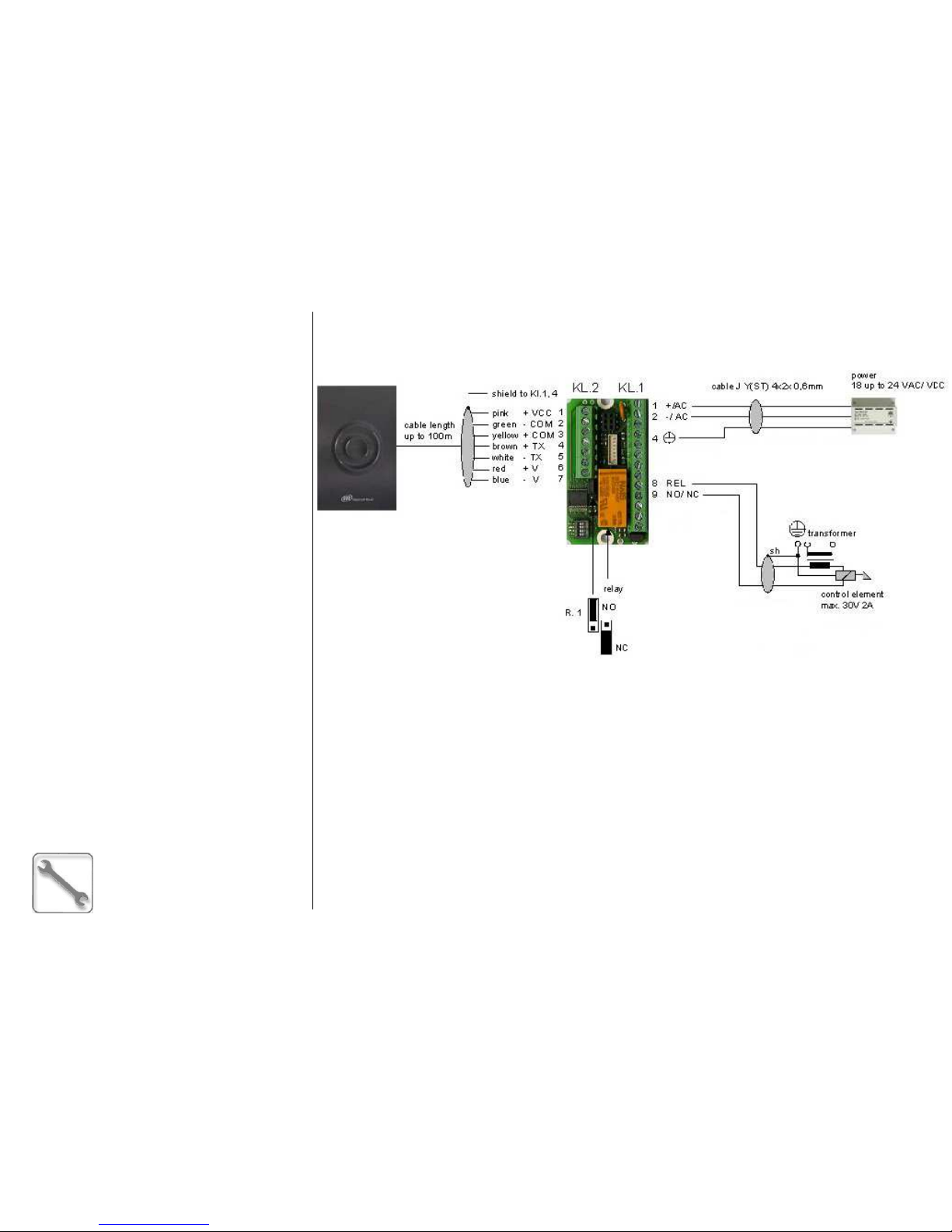
ESIGNO_SYSTEM_USER_MANUAL_101.DOCX 68/71
MMMMAINTENANCE
AINTENANCEAINTENANCE
AINTENANCE
(5)
(5)(5)
(5)
SSSSERVICE
ERVICE ERVICE
ERVICE O
OO
OPERATIONS
PERATIONSPERATIONS
PERATIONS
eeee
SIGNO
SIGNOSIGNO
SIGNO
WWWW
ALL READER
ALL READERALL READER
ALL READER
IIII
NSTALLATION
NSTALLATIONNSTALLATION
NSTALLATION
SSSS
YNCHRONIZATION
YNCHRONIZATIONYNCHRONIZATION
YNCHRONIZATION
If the wall reader remains without power supply for several hours, it must be synchronized once again
in order to work fine. To achieve this, issue a Synchronization Card from the Service Cards Menu of the
eSIGNO Mobile in HHI mode and present it to the wall reader. If the card is correctly read, the wall
reader gives 2 green and red blinks, together with 2 acute beeps.
Note
NoteNote
Note: when a user card is presented to a not synchronized wall reader, it gives 5 red blinks together
with 5 beeps.
In order to obtain the desired behavior of the relay, set the
jumper in the correct way
Relay connection
Wall reader connection
Page 69
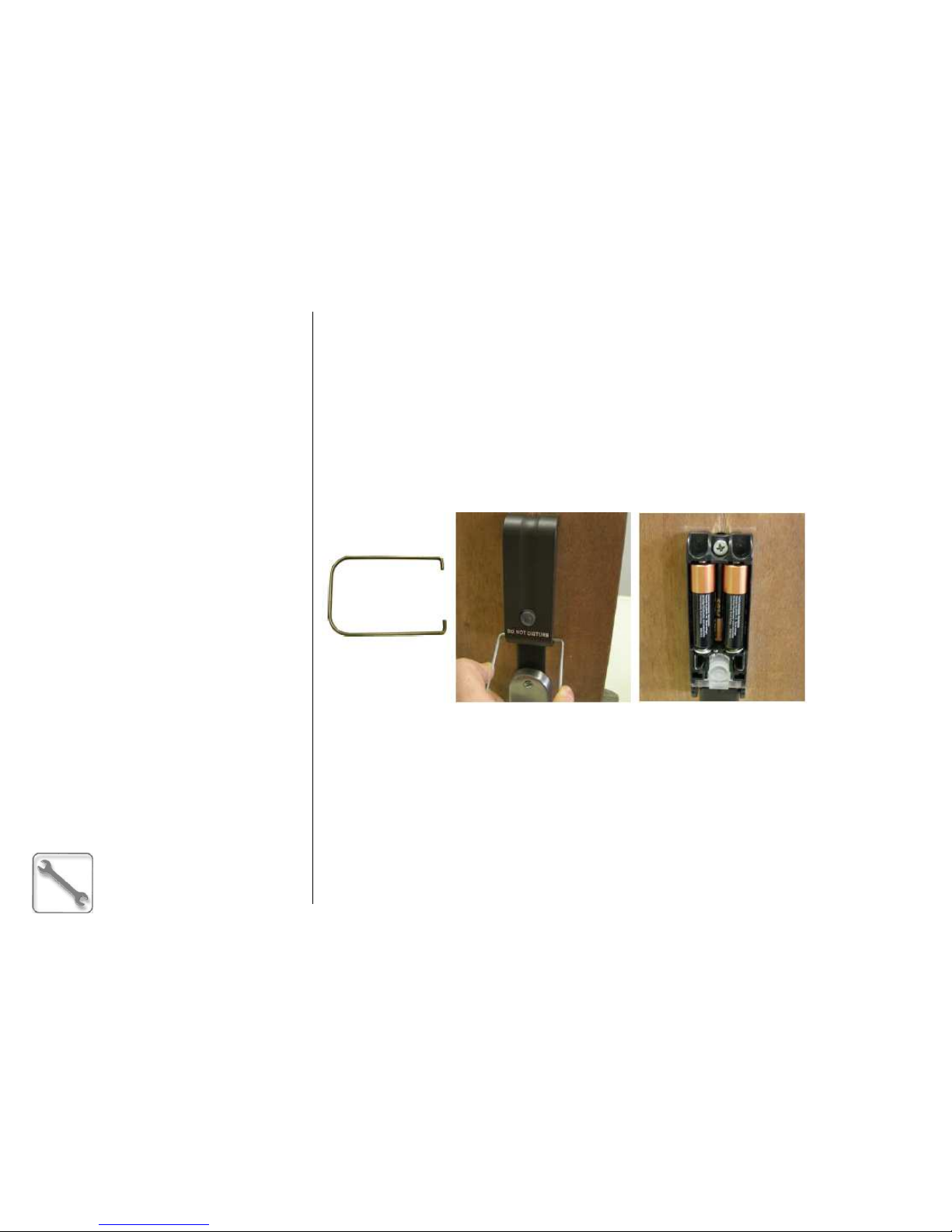
ESIGNO_SYSTEM_USER_MANUAL_101.DOCX 69/71
MMMMAINTENANCE
AINTENANCEAINTENANCE
AINTENANCE
((((6666))))
SSSSERVICE
ERVICE ERVICE
ERVICE O
OO
OPERATIONS
PERATIONSPERATIONS
PERATIONS
WWWW
AVE
AVE AVE
AVE
MMMM
ODE
ODE ODE
ODE
LLLL
OCK
OCKOCK
OCK
BBBB
ATTERY
ATTERY ATTERY
ATTERY
SSSS
TATUS
TATUSTATUS
TATUS
The battery status control can be done using any valid staff card; there are 2 different warning levels:
• low battery status: the LED signal gives 3 red + green blinks before lock opening;
• end battery status: the LED signal gives 12 red + green blinks before lock opening.
These warnings are also recorded into lock history as separate events with respect to the openings.
Steps to change batteries:
Steps to change batteries:Steps to change batteries:
Steps to change batteries:
With the proper tool, it is possible to remove the batteries holder cover as shown in figure below. 3
alkaline AA LR6 type batteries are needed.
EEEE
MERGENCY
MERGENCY MERGENCY
MERGENCY
MMMM
ECHANICAL
ECHANICAL ECHANICAL
ECHANICAL
CCCC
YLINDER
YLINDERYLINDER
YLINDER
The electronic locks always have an emergency mechanical cylinder with variable key bitting.
The cylinder works with 3 different keys (number from 1 to 3):
• key number 1 must be used first;
• in case of key number 1 has been lost or has not been considered secure, key number 2 can be
used. In this case the use of the key number 1 is blocked;
• in the same way, using key number 3, key number 2 will be disabled.
Independently from the key you are using, follow this procedure:
• insert the mechanical key and turn 360° in the clockwise direction;
• rotate the knob (external handle).
Page 70
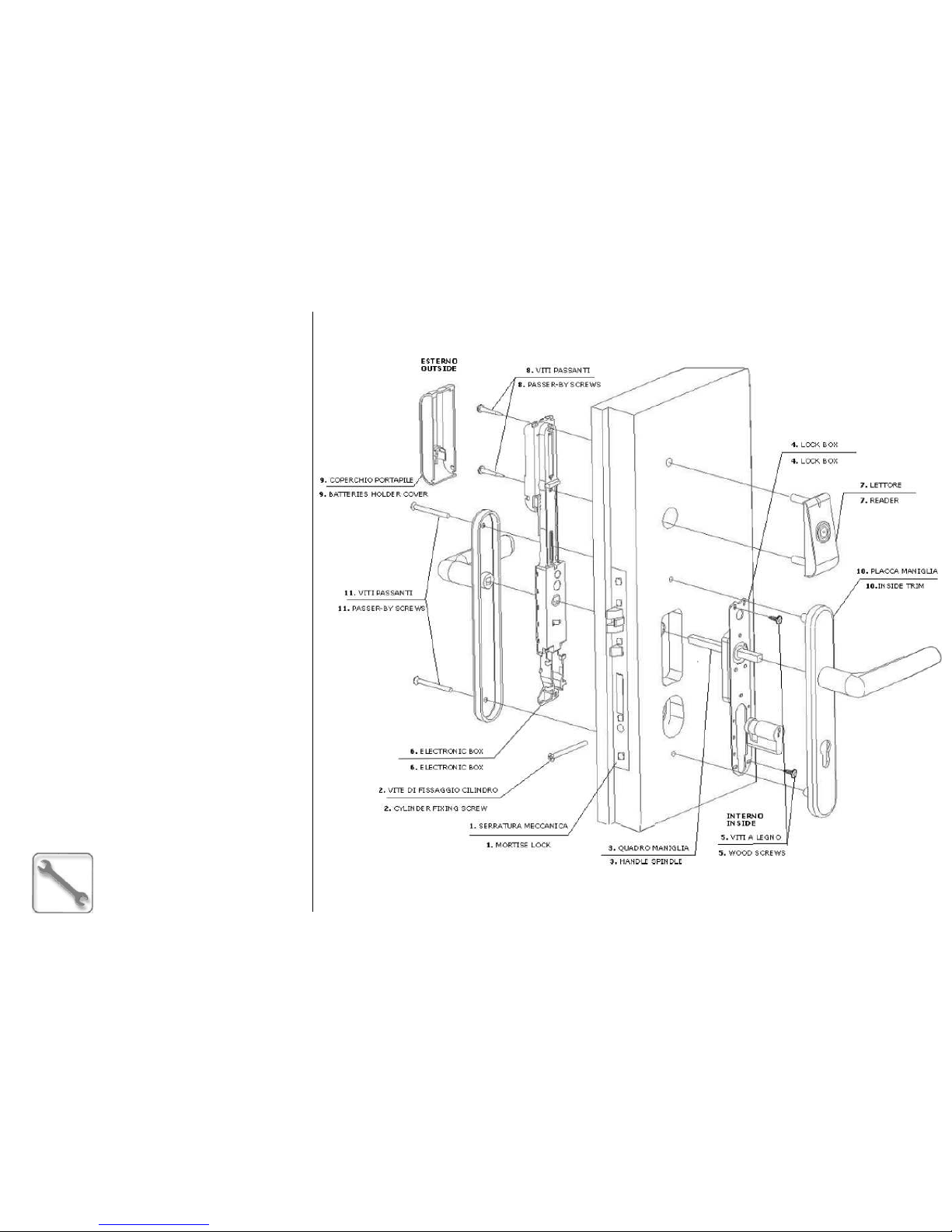
ESIGNO_SYSTEM_USER_MANUAL_101.DOCX 70/71
MMMMAINTENANCE
AINTENANCEAINTENANCE
AINTENANCE
((((7777))))
SSSSERVICE
ERVICE ERVICE
ERVICE O
OO
OPERATIONS
PERATIONSPERATIONS
PERATIONS
WWWW
AVE
AVE AVE
AVE
MMMM
ODE
ODE ODE
ODE
LLLL
OCK
OCK OCK
OCK
IIII
NSTALLATION
NSTALLATIONNSTALLATION
NSTALLATION
Page 71

ESIGNO_SYSTEM_USER_MANUAL_101.DOCX 71/71
Ingersoll Rand’s Security Technologies Sector is a leading global provider of products and services that make environments sa
fe, secure and productive. The
sector’s market-leading products include electronic and biometric access-control systems; time-and-attendance and personnel scheduling systems;
mechanical locks; portable security; door closers, exit devices, architectural hardware, and steel doors and frames; other technologies and services for global
security markets.
www.ingersollrand.com
CISA S.p.A.
Via Oberdan, 42
48018 Faenza (RA) Italy
Tel. +39 0546 677111
Fax +39 0546 677577
E-mail: [email protected]
www.cisa.com
© 2009 Ingersoll-Rand Company Limited
 Loading...